Embed Size (px)
Citation preview

Soil Gas Collector MatRadon, Moisture and VOC’s
Expanded view of Mat
Future Solution Now
New Construction
Radon Reduction Material for
Time Saving, Low Cost
Easy Installation
Reduce Liability
RADON CONTROL SYSTEM FOR NEW BUILDING CONSTRUCTION
According to the U.S. EPA’s model standards for radon control systems in new building construction, a means for collect- soil gas should be installed beneath the slab.
More and more mitigators and builders are using Soil Gas Collector (SGC) matting because its installation does not entail any special coordination with the plumbers. Just lay it down around the inside of the foundation, secure it with spikes or landscaping staples, and pour the concrete
.
ing
SGC matting is superior to other mat systems because it comes with a fabric cloth completely around it. This feature eliminates the need to lay a plastic sheet on top of the matting to prevent the concrete from entering the matrix. Using plastic sheeting can cause concrete cracking due to differential dewatering. The full fabric design greatly enhances both the installation as well as the quality of the concrete slab. When SGC matting is installed below the slab, you’re providing an airspace that intercepts radon before it seeps into the basement, or through the slab. SGC matting also works well as a soil gas collector beneath the plastic in sub-membrane system for crawl spaces.
Another key element of a soil gas collection system is attaching the 4-inch riser to the matting, such that airflow restriction does not occur at this critical
juncture. This soil gas “T
-Riser is unique because it has special ports, which allow each end of the SGC loop to enter the collection box without special connectors.
WHY AND HOW IT WORKS
The matting is a 1-inch high by 12-inch wide matrix enveloped in a polyester filter fabric. 90% of the geomatrix is airspace, which means radon has room to move to the collection point. The matting can support concrete without compressing, yet it is lightweight enough for easy handling.
This system allows the radon to flow through the filter fabric and into the airspace. The airspace does not clog because the filter fabric retains the underlying gravel and soil. The natural airflow through the SGC matting then channels the radon to the pipe connection. From there, the gas can be routed outdoors. If high radon levels persist, inline fans can easily be installed to create greater airflow.
juncture. This soil gas T
Exhaust Port: SGC “T-Riser”, this uniquely designed port will allow the SGC Matting to enter the collection box, maximizing airflow without the need for special connectors. The T-Riser will extend above the concrete floor and provides for a 4 inch or 6 inch connection to PVC pipe for easy exhaust
Soil Gas Mat 45” roll
Soil Gas Mat T-Riser
T-Riser
.

SIDE VIEW GOING THRU FOOTER/ INTERMEDIATE WALL
SOIL GAS MAT SOIL GAS MAT
PVC PIPE
FOOTER/INTERMEDIATE WALL
Soil Gas Mat
TOP VIEW GOING THRU WALLVAPOR VENT THROUGH FOOTER
GRAVEL OR DIRT UNDER MAT
Soil Gas Mat
FOOTER
INTERMEDIATE WALL
Soil Gas Mat

Optional Fittings
T- Riser End Cap Flat Outlet
End Outlet External Split CouplerFlat WYE
Configuration: Material dimensions are 12 inches wide, 1 in deep, by 45 foot in length, with core material completely covered with fabric.
Core Properties: Core material, made of high-strength, waffle-like, double-sided, lightweight polystyrene plastic, capable of withstanding 4300 PSF.
Fabric Properties: Ligtweight fabric that completely encloses the core to prevent concrete from entering the matrix and allowing flow of Radon Gas to filter through the fabric into the airspace. Fabric tested to ASTM standards for tensile strength, puncture strength, permeability and other properties essential to the overall performance of this material.
Air Space Envelope: 90% of the geomatrix will be comprised of airspace. The core material design and fabric cover configuration will maximized airflow allowing Radon Gas to be easily channeled to the collection point for removal.
Installation Properties: Installed in a continuous loop around the interior of the foundatioin prior to the concrete being poured. Easily cut and spliced to form a continuous loop and secured with staples.
Specifications

Product Data Sheet
Material Physical Proper�es Cuspated Plastic Property Test Method Value Speci�c Gravity (g/cc) ASTM D-792 1.04 Melt Flow @ 200°C/5000g (g/10 min) ASTM D-1238 2.5 Tensile Strength @ Yield (psi) ASTM D-638 2,900 Tensile Modulus (psi) ASTM D-638 275,000 Elongation @ Break (%) ASTM D-638 70 Flexural Modulus (psi) ASTM D-790 300,000 Impact Strength, Notched Izod @ 73°F (ft-lb/in) ASTM D-256 2.1
Heat De�ection Temperature @ 264 psi (°F) ASTM D-648 183 Vicat Softening Point (°F) ASTM D-1525 210 Cover Fabric
Property Test Method Value Grab Tensile (lbs) ASTM D4632 130 Elongation (%) ASTM D4632 > 50 Trapezoid Tear (lbs) ASTM D4533 60 Puncture (lbs) ASTM D4833 41 Mullen Burst (psi) ASTM D3786 140 AOS (U.S. sieve number) ASTM D4571 70 Permittivity (sec-1) ASTM D4491 0.8 Permeability (cm/sec) ASTM D4491 0.04 Water Flow (gal/min/sf) ASTM D4491 60 UV Stability (%) ASTM D4355 70
Binding Method Property Test Method Value External Binder Standard Sewn Type Stitching Standard Lock Stitch Type Thread Standard HB92 Nylon Tensile Strength (lbs) ASTM D4632 11 Thread Gage Standard 2 IOx4 denier Chemically Impervious Standard MI Natural
Optional Fittings
T- Riser End Cap Flat Outlet
End Outlet External Split CouplerFlat WYE
Configuration: Material dimensions are 12 inches wide, 1 in deep, by 45 foot in length, with core material completely covered with fabric.
Core Properties: Core material, made of high-strength, waffle-like, double-sided, lightweight polystyrene plastic, capable of withstanding 4300 PSF.
Fabric Properties: Ligtweight fabric that completely encloses the core to prevent concrete from entering the matrix and allowing flow of Radon Gas to filter through the fabric into the airspace. Fabric tested to ASTM standards for tensile strength, puncture strength, permeability and other properties essential to the overall performance of this material.
Air Space Envelope: 90% of the geomatrix will be comprised of airspace. The core material design and fabric cover configuration will maximized airflow allowing Radon Gas to be easily channeled to the collection point for removal.
Installation Properties: Installed in a continuous loop around the interior of the foundatioin prior to the concrete being poured. Easily cut and spliced to form a continuous loop and secured with staples.
Specifications

Soil Gas Collector Installation Instructions
1. Lay out the Soil Gas Collector (SGC) on the sub grade after the final preparation and before the concrete is poured. It is typically laid out in a rectangular loop in the largest area with branches or legs into the smaller areas.
2. Position the T-Riser in appropriate location and nail down with a 12-inch spike through hole in center.
3. Slide the SGC into openings in T-Riser with a portion of the fabric around the outside. Tape the fabric to the outside of the T-Riser with duct tape and staple the SGC to the ground with a landscaping staple near the T-Riser.
4. Roll out the SGC, smooth it onto the ground. To avoid wrinkles and buckling, work away from the T-Riser, stapling it to the ground as you go. The SGC should be stapled to the ground every three to four feet, in addition to the corners, tee’s, and ends.
5. Corners are constructed by peeling back the filter fabric, cutting the two ends of the SGC matrix at 45° angles and butting (or overlap no more than 1/2 inch) the matrix together. Pull the filter fabric back and tape into place. Staple across the joint of the matrix and each leg of the corner. Use a minimum of four staples at each corner - two across the joint and one on each leg.
6. The tees for branches or legs are constructed by slitting the fabric of the main loop at the location desired. Cut the fabric of branch at the edges and expose 2 inches of the matrix. Cut off the exposed matrix and butt the matrix of the branch (or overlap no more than 1/2 inch) to the matrix of the main loop. Pull the filter fabric of the branch back over the main loop and tape into place. Staple across the joint of the matrix with two staples and one each on the branch and the main loop. Use a minimum of four staples at each tee, two across the joint and one on each on the loop and branch
7. All openings in the fabric at joints, tee’s, and ends of the branches should be taped to keep out the concrete.
8. When the building is ready for the soil gas vent pipe to be installed, the top of the T-Riser is cut off and a four-inch pipe is inserted, caulked with polyurethane, and secured with screws. The vent pipe should be labeled to avoid confusion with the plumbing pipes.
Note:
The openings in the riser are laid out at 180 deg. to accommodate straight runs of SGC only. If the riser is to be located in a corner, which is not uncommon, the front of the tee can be cut off and the SGC inserted into the new opening. The side of the tee which will not be used should be sealed with duct tape. This creates a 90 deg tee which will allow the riser to be placed in a corner with either end of the SGC loop running into the tee at a 90 deg angle.

Where is SGC most widely applied?
SGC is the most efficient and cost effective methods for creating sufficient permeability beneath concrete floors to allow for the capture and exhaust of naturally occurring radon gas. Advantages:
•
Ease of installation:
o
Time to install is minimized, reducing labor costs
o
Ease of installation reduces heavy machinery costs
o
SGC is laid on top of the soil sub grade prior to concrete pouring, making it the last item to be installed; no other trades can disturb or hinder installation
•
Reduce material costs:o
Additional Aggr eate is not necessaryo
Additional plastic barrier is not needed, and in most cases not desired
•
Passive system:
o
In most cases the SGC will function as a passive system when the pipe stack is run through the interior of the structure and vented out the roof
T-Riser has special hole for a spike to secure it in place
Proper caulking and sealing of the slab area is also recommended.
.For best performance it is recommended that a “T-Riser” and stack vent, (min. 4 inch schedule 40) be installed every 2000 sq. ft.
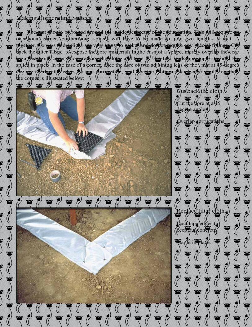
Making Corners and Splices
The mat should be routed around the inside perimeter of the foundation. This will require an occasional corner. Furthermore, splices will have to be made to join two lengths of mat together. Corners and splices are very easy to make, and do not require any special fittings. Cut back the filter fabric to expose the core material. In the case of a splice, merely overlap the core by at least one corrugation, replace the cloth, and tape it. Use two landscape staples to hold the splice in place. In the case of a corner, slice the core of two adjoining legs of the mat at 45-degree angles, overlap the edges by one corrugation, and tape the cloth and landscape staple together. The the corner is illustrated below:
Cut back the cloth. Cut the core at a 45 degree angle. Overlap corrugations
Replace filter cloth Duct tape edges to keep out concrete. Staple in place.

Connecting The Mat To The Riser A convenient T-Riser with a dual entry allows for either end of the loop of mat to be secured to the soil gas vent riser.
Slide the mat into either end of the riser and tape the edge to prevent wet concrete from entering. The riser comes with a molded cap to keep out concrete Later this cap can be cut off and the 4" Sch. 40 PVC riser can be inserted, screwed, and caulked into place..
Risers are often placed in corners for convenience of later pipe routing. The plastic riser “tee” can be cut to allow for such situations.

Pouring Concrete: The filter fabric that comes sewn around the soil gas collector prevents the wet concrete from entering the mat and reducing its air collection capacity. The only precaution that needs to be taken is that the fabric is duct taped closed at seams of splices and corners sufficiently to keep the uncured concrete from entering. The mat also needs to be secured to the soil with landscape staples to prevent the concrete from lifting it off the soil while it is being applied. Reinforcing bars and wire can be laid right on top of the mat.
Note that the mat is strong enough to withstand concrete workers and their wheelbarrows as they cross over it during the course of installing the slab.
Professional Discount SupplyColorado Springs, CO 80916 719-444-0646 www.radonpds.com