Embed Size (px)
Citation preview
Software Synthesis for Control System
Algorithms in Industrial Applications
Emmanuel Roy – The MathWorks
WorkShop on Software Synthesis
Friday, Oct. 16th, 2009, Grenoble, France
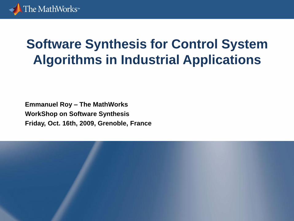
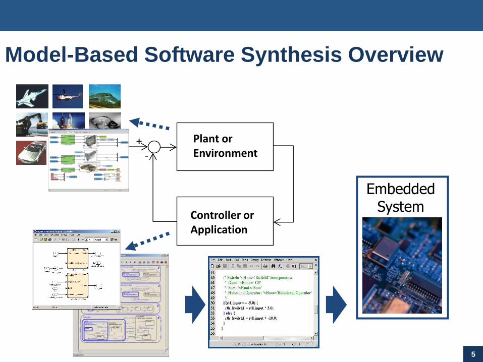
Model-Based Software Synthesis Overview
2
Plant orEnvironment
Controller orApplication
+-
EmbeddedSystem

Model-Based Software Synthesis Overview
3
Plant orEnvironment
Controller orApplication
+-
EmbeddedSystem
•High level of Abstraction:•Dynamic typing•Dynamic sizing•Type and rate propagation•Concise math representation•…
•Hierarchical Algorithm design•Complexity decomposition•Reuse
•« Simulable » (executable specification)•Multi-Domain Modelling•Early Verification&Validation•Powerful visualization possibilities•…
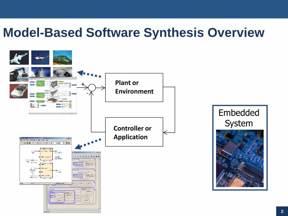
Model-Based Software Synthesis Overview
4
Plant orEnvironment
Controller orApplication
+-
EmbeddedSystem
Embedded MATLAB
Stateflow
Simulink
Multiple Targets
Analysis/
Transform
Intermediate
Representation (IR)
IR
Target Language
Backend
C
C++
HDL
Simscape
Multiple analyses and optimizations
Multiple domains
Analysis/
Transform
Model-Based Software Synthesis Overview
5
Plant orEnvironment
Controller orApplication
+-
EmbeddedSystem
Model-Based Software Synthesis Key
Benefits
Separate algorithm from implementation
Parameterizeable implementations
Target independence
Flexibility and reusability
Multi (targeted) language support
6
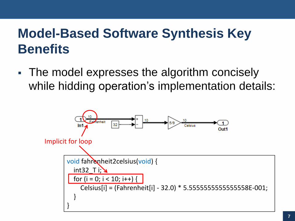
Model-Based Software Synthesis Key
Benefits
The model expresses the algorithm concisely
while hidding operation’s implementation details:
7
void fahrenheit2celsius(void) {int32_T i;for (i = 0; i < 10; i++) {
Celsius[i] = (Fahrenheit[i] - 32.0) * 5.5555555555555558E-001;}
}
Implicit for loop
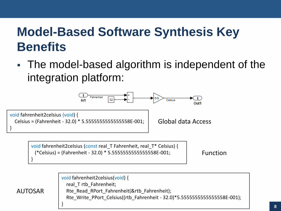
Model-Based Software Synthesis Key
Benefits
The model-based algorithm is independent of the
integration platform:
8
void fahrenheit2celsius (void) {Celsius = (Fahrenheit - 32.0) * 5.5555555555555558E-001;
}
void fahrenheit2celsius (const real_T Fahrenheit, real_T* Celsius) {(*Celsius) = (Fahrenheit - 32.0) * 5.5555555555555558E-001;
}
void fahrenheit2celsius(void) {real_T rtb_Fahrenheit;Rte_Read_RPort_Fahrenheit(&rtb_Fahrenheit);Rte_Write_PPort_Celsius((rtb_Fahrenheit - 32.0)*5.5555555555555558E-001);
}
Global data Access
Function
AUTOSAR
Model-Based Software Synthesis Key
Benefits
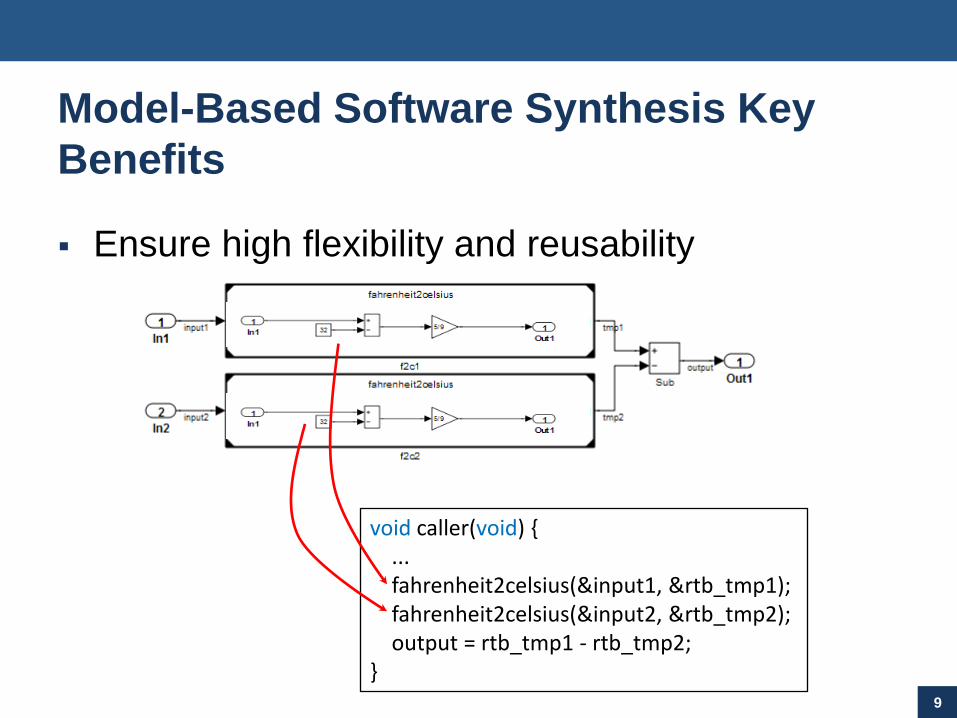
Ensure high flexibility and reusability
9
void caller(void) {...fahrenheit2celsius(&input1, &rtb_tmp1);fahrenheit2celsius(&input2, &rtb_tmp2);output = rtb_tmp1 - rtb_tmp2;
}
Model-Based Software Synthesis Key
Benefits
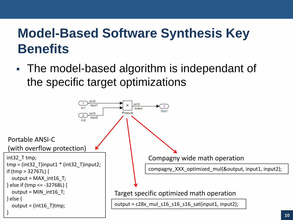
The model-based algorithm is independant of
the specific target optimizations
10
int32_T tmp;tmp = (int32_T)input1 * (int32_T)input2;if (tmp > 32767L) {
output = MAX_int16_T;} else if (tmp <= -32768L) {
output = MIN_int16_T;} else {
output = (int16_T)tmp;}
Portable ANSI-C (with overflow protection)
output = c28x_mul_s16_s16_s16_sat(input1, input2);
Target specific optimized math operation
compagny_XXX_optimized_mul(&output, input1, input2);
Compagny wide math operation

Model-Based Software Synthesis Key
Benefits
Automatic mapping of functional rates into
software tasks (RM based scheduler)
11
Fastest rateSlowest rate
void task_fastest(void) {.../* RateTransition: '<Root>/RateTransition' */if ((rtM->Timing.RateInteraction.TID0_1 == 1)) {
rtB.RateTransition = rtDWork.RateTransition_Buffer0;}...
}
void task_slowest(void) {...
}
Model-Based Software Synthesis Key
Benefits
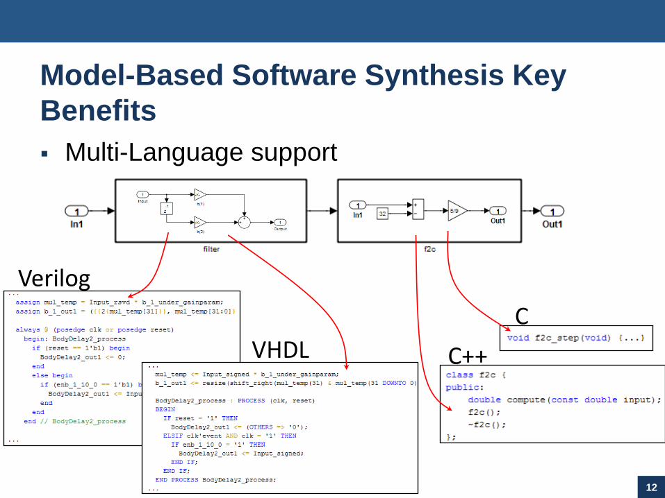
Multi-Language support
12
C
C++
Verilog
VHDL
13
Architectural Complexity
Alg
orith
mic
Co
mp
lexity
Hand CodeArchitecture
Tool
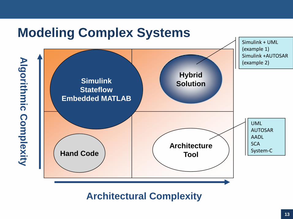
Modeling Complex Systems
Simulink
Stateflow
Embedded MATLAB
Hybrid
Solution
UMLAUTOSARAADLSCASystem-C
Simulink + UML (example 1)Simulink +AUTOSAR (example 2)
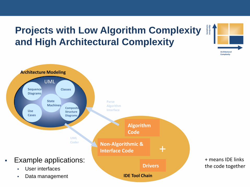
Projects with Low Algorithm Complexity
and High Architectural Complexity
+ means IDE links the code together
Example applications: User interfaces
Data management
Architectural Complexity
Algo
rithm
ic C
om
plexity
Architecture Modeling
UML
UseCases
ClassesSequenceDiagrams
CompositeStructureDiagrams
Algorithm Code
Non-Algorithmic & Interface Code +
Drivers
IDE Tool Chain
UML Coder
Parse Algorithm Interface
StateMachines
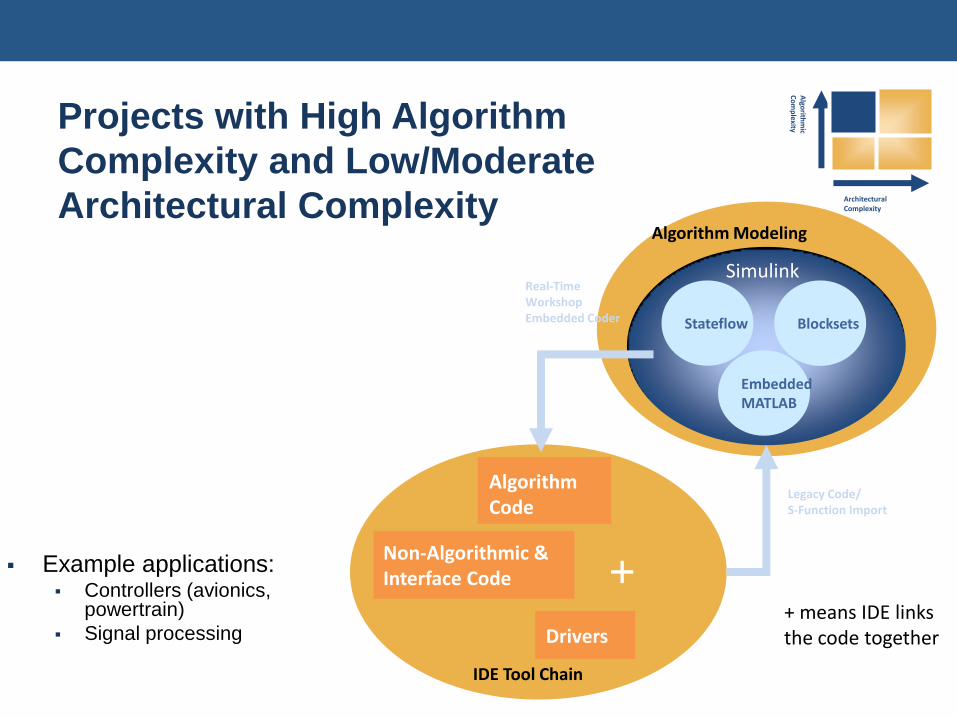
Projects with High Algorithm
Complexity and Low/Moderate
Architectural Complexity
+ means IDE links the code together
Example applications: Controllers (avionics,
powertrain)
Signal processing
Architectural Complexity
Algo
rithm
ic C
om
plexity
Algorithm Modeling
EmbeddedMATLAB
Simulink
Blocksets
Real-Time Workshop Embedded Coder
Legacy Code/ S-Function Import
Stateflow
Algorithm Code
Non-Algorithmic & Interface Code +
Drivers
IDE Tool Chain
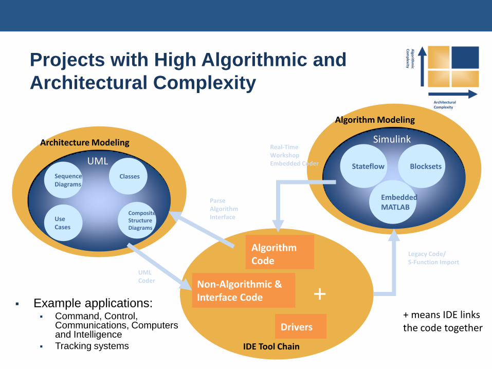
Projects with High Algorithmic and
Architectural Complexity
+ means IDE links the code together
Architectural Complexity
Algo
rithm
ic C
om
plexity
Example applications: Command, Control,
Communications, Computers and Intelligence
Tracking systems
Architecture Modeling
UML
UseCases
ClassesSequenceDiagrams
CompositeStructureDiagrams
Algorithm Modeling
EmbeddedMATLAB
Simulink
Blocksets
Legacy Code/ S-Function Import
Stateflow
Algorithm Code
Non-Algorithmic & Interface Code +
Drivers
IDE Tool Chain
UML Coder
Parse Algorithm Interface
Real-Time Workshop Embedded Coder
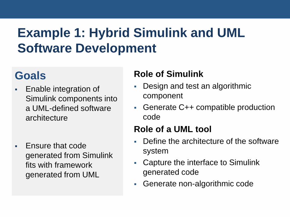
Example 1: Hybrid Simulink and UML
Software Development
Goals Enable integration of
Simulink components into
a UML-defined software
architecture
Ensure that code
generated from Simulink
fits with framework
generated from UML
Role of Simulink
Design and test an algorithmic
component
Generate C++ compatible production
code
Role of a UML tool
Define the architecture of the software
system
Capture the interface to Simulink
generated code
Generate non-algorithmic code

Mapping a Model to a “Component” Class
1. Build model (or atomic subsystem)
2. Generate code for
model/subsystem*
3. Create a class for the subsystem
4. Relate operations to function
members in code
5. Relate attributes to data
members in code
In1
In2
Out1
Out2
ComponentSubsystem
class ComponentSubsystem {
public:
void initialize(void);
void terminate(void);
int16_T step_method(real_T &arg_In1,
real_T *arg_In2, boolean_T *arg_Out2);
ComponentSubsystem(void);
~ComponentSubsystem();
RT_MODEL * getRTM(void);
protected:
ExternalOutputs rtY;
private:
RT_MODEL *rtM
};
+initialize();+terminate();+step_method(in real_T arg_In1,
in real_T arg_In2, out boolean_T arg_Out2) int16_T
+ComponentSubsystem();+~ ComponentSubsystem();+getRTM(): RT_MODEL
#rtY: ExternalOutputs -rtM: RT_MODEL
ComponentSubsystem
* Uses automatic C++ encapsulation feature

Parse C++ header files into UML classes
If Simulink model
changes, regenerate the
code and re-parse.
Automated Code-Level Integration Approach
Simulink and
Stateflow
Real-Time Workshop
Embedded Coder C++ Generator
C++
UML Tool
C++
Code from Real-Time Workshop Embedded Coder with C++ option
C++ code from UML tool
Compile and link code files from both sources
Code
Integration
Environment

Example 2: Model-Level Integration with
AUTOSAR (Automotive Open System Architecture)
20
AUTOSAR Goals
Implement and standardize on a single platform as an OEM-wide “Standard Core” solution
Enable OEMs/suppliers to focus on added value
AUTOSAR Key Technologies*
Basic Software
Software architecture including a complete basic (environmental) software stack for an ECU as an integration platform for hardware-independent software applications
Methods of Software Integration
Exchange formats (templates) to enable a seamless configuration process of the basic software stack and the integration of application software in ECUs
Functional API
Specification of functional interfaces as a standard for application software modules
*Source: Helmut Fennel, OOP 2007
21
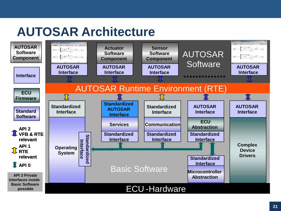
AUTOSAR Architecture
ECU -Hardware
AUTOSAR Runtime Environment (RTE)
ActuatorSoftware
Component
AUTOSARInterface
ApplicationSoftware
Component
SensorSoftware
Component
ApplicationSoftware
Component
..............
AUTOSARSoftware
Basic Software
StandardizedInterface
AUTOSARInterface
AUTOSARInterface
AUTOSARInterface
MicrocontrollerAbstraction
AUTOSARSoftware
Component
Interface
ECUFirmware
StandardSoftware
StandardizedAUTOSARInterface
Services
StandardizedInterface
ECUAbstraction
AUTOSARInterface
StandardizedInterface
ComplexDeviceDrivers
AUTOSARInterface
API 2VFB & RTErelevant
StandardizedInterface
Communication
StandardizedInterface
StandardizedInterface
OperatingSystem
API 1RTErelevant
API 0
Sta
nd
ard
ize
d
Inte
rfac
e
API 3 PrivateInterfaces inside Basic Software
possible ECU -Hardware
AUTOSAR Runtime Environment (RTE)
ActuatorSoftware
Component
AUTOSARInterface
ApplicationSoftware
Component
SensorSoftware
Component
ApplicationSoftware
Component
..............
AUTOSARSoftware
Basic Software
StandardizedInterface
AUTOSARInterface
AUTOSARInterface
AUTOSARInterface
MicrocontrollerAbstraction
AUTOSARSoftware
Component
Interface
ECUFirmware
StandardSoftware
StandardizedAUTOSARInterface
Services
StandardizedInterface
ECUAbstraction
AUTOSARInterface
StandardizedInterface
ComplexDeviceDrivers
AUTOSARInterface
API 2VFB & RTErelevant
StandardizedInterface
Communication
StandardizedInterface
StandardizedInterface
OperatingSystem
API 1RTErelevant
API 0
Sta
nd
ard
ize
d
Inte
rfac
e
API 3 PrivateInterfaces inside Basic Software
possible
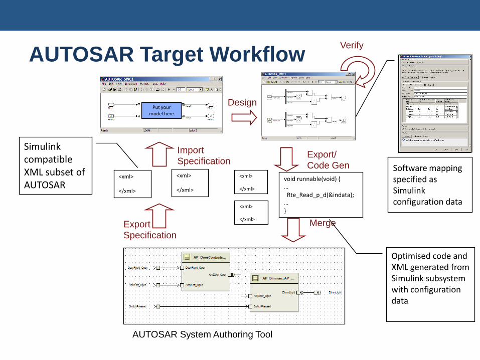
AUTOSAR Target Workflow
Design
AUTOSAR System Authoring Tool
Import
Specification
ExportSpecification
<xml>
</xml>
<xml>
</xml>
Export/Code Gen
Merge
<xml>
</xml>
<xml>
</xml>
void runnable(void) {…Rte_Read_p_d(&indata);…}
Verify
Put your model here
Simulink compatible XML subset of AUTOSAR
Optimised code and XML generated from Simulink subsystem with configuration data
Software mapping specified as Simulink configuration data
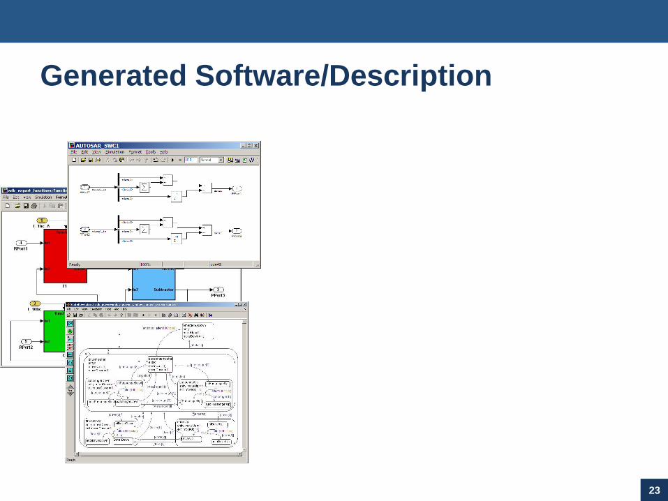
Generated Software/Description
23
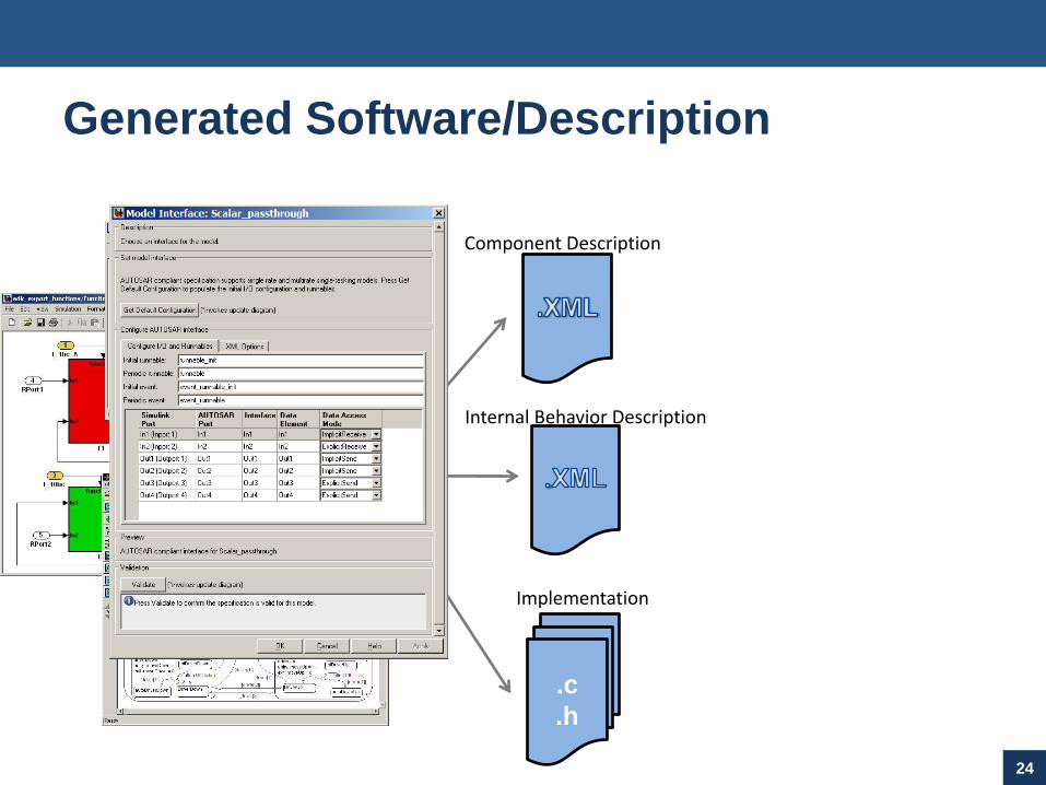
Generated Software/Description
24
.c
.h
Implementation
Internal Behavior Description
Component Description
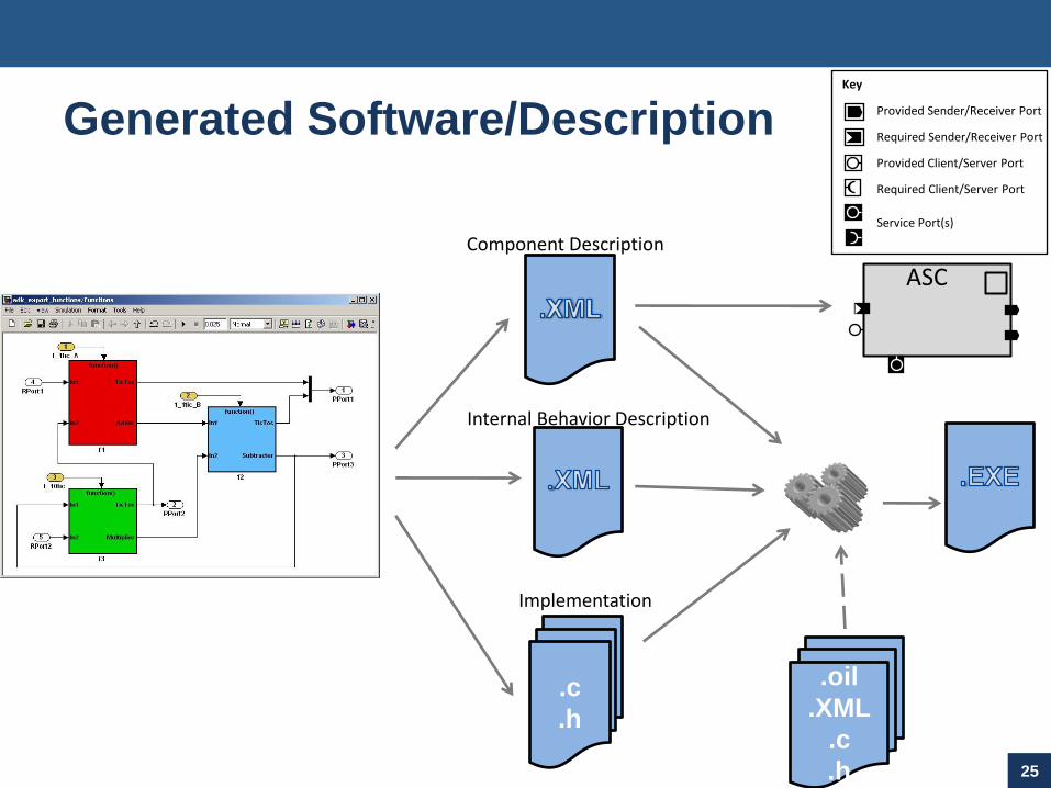
Generated Software/Description
25
Key
Provided Sender/Receiver Port
Required Sender/Receiver Port
Provided Client/Server Port
Required Client/Server Port
Service Port(s)
ASC
.c
.h
Implementation
Internal Behavior Description
Component Description
.oil
.XML
.c
.h
Conclusion
Simulink is the established environment for algorithm development Rich design and verification environment Route to production code
Software architectures are becoming more complex A number of languages are emerging for the description of software
architectures Need to present algorithmic models as components for integration Three main activities
Characterize an algorithmic model for optimal use in software Adapt an algorithmic model to the demands of the application Publish the adapted model for use in a given platform
Challenges in supporting collaboration between software engineer and algorithm designer Providing a framework within Simulink that allows the software engineer to prepare
an algorithm for deployment into a software architecture
Maintaining a consistent representation of the algorithm in both environments
Generating the required artefacts to support integration with the software engineer’s design flow


![A Novel Synthesis Algorithm for Reversible Circuitssportlab.usc.edu/~msaeedi/slides/ICCAD_2007.pdf · 12 Synthesis Algorithms Categories (Cnt’d) Search-based methods [15],[17] Also](https://img.dokumen.tips/doc/110x75/5fb54240b2443c014f3a9811/a-novel-synthesis-algorithm-for-reversible-msaeedislidesiccad2007pdf-12-synthesis.jpg)