Embed Size (px)
Citation preview

AN1074Software PWM Generation for LED Dimming and RGB Color Applications
INTRODUCTION
This application note describes a software solution thatgenerates one or more pulse-width modulated (PWM)signals using a PIC® microcontroller (MCU). PWM con-trol signals are widely used in embedded control appli-cations for a variety of tasks that include light dimming,motor speed control, output voltage control, andcommunication between devices.
It is convenient and sometimes more practical to use aMCU that has dedicated PWM peripherals for thesetypes of applications. However, a software PWM solu-tion allows a less expensive MCU to be used if the fre-quency and resolution requirements for the applicationare not too high. Furthermore, the software solutioncould be used to provide additional PWM channels ifthe number of PWM peripherals on the MCU is notsufficient.
Pulse-width modulation is an effective way to controlthe brightness of LEDs. As a demonstration, the soft-ware PWM solution will be applied to control the coloroutput of an RGB LED (OPTEK modelOVSTRGBBCR8). By generating three software PWMsignals red, green, blue or any mix of color, can begenerated.
Recent advances in LED technology have allowedLEDs to be used as efficient sources of illumination.The RGB demonstration has a wide range of applica-tions, including automotive interior lighting,architectural lighting, and LCD display backlighting.
A PIC12HV615 microcontroller device was chosen forthe RGB demonstration. The PIC12HV615 is a verylow-cost 8-pin MCU with an internal RC oscillator anda shunt voltage regulator. The device has many on-chipperipherals, including: a comparator, an ADC, a Cap-ture/Compare/PWM (CCP) module, and three timers.The features, low cost, and small size of thePIC12HV615 allow a user to add the intelligence of aMCU to almost any application.
The first part of this application note will show you howto generate software PWM signals using the Timer0peripheral, which is available on most PIC MCUs. Thesecond part will show you how to use the PWM code forthe RGB color demonstration.
HOW PULSE-WIDTH MODULATION WORKS
Pulse-width modulation is one of the most widely usedoutput techniques available to the embedded design-ers. PWM can also convey analog information in a dig-ital format. The amplitude of an analog signal isencoded in terms of the on-time and off-time ratio (dutycycle) of a PWM period.
A PWM signal has a fixed frequency. The width (W) ofeach pulse varies between 0 and the period (T). Theduty cycle (D) of a signal is the ratio of pulse width toperiod. Figure 1 shows a PWM output waveform.
FIGURE 1: PWM OUTPUT
Figure 2 shows a PWM output at a 10% duty cycle (i.e.,the signal is on for 10% of the period and off for theother 90%). Figures 3 and 4 show PWM output at 50%and 90% duty cycles, respectively.
Author: Parthiv PandyaMicrochip Technology Inc.
W
TD=
W T
© 2007 Microchip Technology Inc. DS01074A-page 1

AN1074
FIGURE 2: 10% DUTY CYCLE
FIGURE 3: 50% DUTY CYCLE
FIGURE 4: 90% DUTY CYCLE
USING PWM DIMMING TO CONTROL LED BRIGHTNESS
A LED is a current-controlled device. Figure 5 shows asimple LED application circuit.
FIGURE 5: CIRCUIT TO ILLUMINATE A LED
The light output from a LED is proportional to the cur-rent passing through it. There are two techniques tocontrol the LED brightness in the circuit.
1. Vary the LED drive current. The LED drive cur-rent may be controlled using a variable resistor(R) or using a variable voltage power supply(VDC).
2. Apply pulse-width modulation to the LED drivecurrent.
The first method has two major disadvantages:
1. As the current is reduced the LED efficiencymay also be reduced.
2. In high power white LEDs, a color shift may takeplace with the reduction in current level.
The PWM dimming technique always drives the LED atfull current. Therefore, problems such as reducedefficiency and color shifts can be eliminated.
Figure 6 shows a circuit to control the brightness withthe PWM dimming technique.
FIGURE 6: PWM DIMMING TECHNIQUE FOR BRIGHTNESS CONTROL
10%
50%
90%
LED
R
VDC
LED
Rc
VCC
PWM
Generator Rb
DS01074A-page 2 © 2007 Microchip Technology Inc.

AN1074
INTERRUPTS
Interrupts are defined as asynchronous events, gener-ated by an external or internal hardware source. Theseevents cause the CPU to interrupt the execution of thecurrent program and to start a service routine, which isdedicated to these events. After the execution of thisInterrupt Service Routine (ISR), the program that wasinterrupted will be resumed. Figure 7 shows theprogram flow when an interrupt is generated.
FIGURE 7: INTERRUPT OPERATION
GENERATING PWM WITH TIMER0
This software solution uses the Timer0 module to con-trol the width of each PWM pulse.
To ensure that the PWM pulsing is not visible to thehuman eye, a 100 Hz PWM signal frequency was cho-sen. To allow for 32 discrete duty cycle values to begenerated, the 10 mSec period was further divided in32 intervals each 312 μSec long (10mSec/32 ~ 312μSec). Therefore, the Timer0 module must be config-ured to generate an interrupt at 312 μSec intervals. If agreater duty cycle resolution is desired, a shorterTimer0 period must be used.
The Timer0 module counts from 0 (or a preloadedvalue) to 255 and rolls over. The interrupt occurs whenthe timer rolls over.
EQUATION 1:
Equation 1 indicates the relationship between theTimer0 pre-loaded value and the resulting interruptperiod. TCY is the microcontroller instruction cycle,obtained by dividing the microcontroller internal clockperiod by four. The microcontroller internal oscillatoroperates at 4 MHz frequency so TCY is determined tobe 1 μSec.
To obtain the desired 312 μSec interval and to ensurethat the PreLoad is an 8-bit value (0-255) the Prescaler,an 8-bit clock divider that can be optionally assigned tothe Timer0 module, is used to double the clock period.(Prescale = 2).
By solving Equation 1 for the PreLoad value, we obtainEquation 2.
EQUATION 2:
Substituting the known values and rounding the resultto the nearest integer value, we obtain the value towrite into Timer0 register after each interrupt event.
SOFTWARE OPERATION
The source code file “SoftwarePWM.asm” suppliedwith this application note generates simultaneouslythree PWM signals of identical period (10 ms) but withindependent duty cycles.
As described in the previous section, Timer0 generatesan interrupt every 312 μSec. In the ISR, the state vari-able IntCount is decremented and tested for zeroand for the desired duty cycle. If IntCount is zero thenall output pins are set. This is the rising edge for allthree PWM signals and the beginning of the PWMperiod. The IntCount value is then set to ‘32’.
If IntCount is not zero then it is compared to thethree duty cycle values: Dutycycle0, Dutycycle1and Dutycycle2. If a match occurs with any one ofthe three duty cycles, the corresponding output pin iscleared. This decides the falling edge for thecorresponding PWM signal.
Interrupt Event
ISR Code Main Loop Code
t
Main Loop Code
Interrupt Period = Prescale x TCY x (256-PreLoad)
PreLoad = 256 - (InterruptPeriod / Prescale x TCY)
PreLoad = 256 - (312 μSec/2 μSec)
PreLoad = 100
© 2007 Microchip Technology Inc. DS01074A-page 3

AN1074
FIGURE 8: PWM SIGNAL
Tim
e
Mai
n Lo
op
Cod
e
ISR
Mai
n Lo
op
Cod
e
ISR
Mai
n Lo
op
Cod
e
ISR
Mai
n Lo
op
Cod
e
ISR
Mai
n Lo
op
Cod
e
ISR
Mai
n Lo
op
Cod
e
ISR
Inte
rrup
t
Eve
nt
Inte
rrup
t
Eve
nt
Inte
rrup
t
Eve
nt
Inte
rrup
t
Eve
nt
Inte
rrup
t
Eve
nt
Inte
rrup
t
Eve
nt
Inte
rrup
t
Eve
nt
312
μSec
t 1
3031
0In
tCou
nt PW
M0
PW
M1
PW
M2
Ris
ing
Edg
e
(Int
Cou
nt =
0)
Fal
ling
Edg
e
(Int
Cou
nt =
Dut
yCyc
le1)
Fal
ling
Edg
e
(Int
Cou
nt =
Dut
yCyc
le2)
Fal
ling
Edg
e
(Int
Cou
nt =
Dut
yCyc
le0)
T=
10
mS
ec
01
229
•
•
•
DS01074A-page 4 © 2007 Microchip Technology Inc.

AN1074
Figure 8 shows how the generated PWM period isdivided into thirty intervals. Each interval correspondsto a Timer0 interrupt period of 312 μSec.
RESOURCES USED BY THE PWM MODULE
1. Program Memory:
The software uses 238 bytes of program mem-ory out of 2048 bytes total. So, program memoryusage is 11.62%.
2. Data Memory (RAM):
The software uses 11 bytes of RAM (Data Mem-ory) out of 128 bytes total. So, RAM usage is8.59%.
3. CPU Bandwidth:
The device operates at 4 MHz clock speed. Thesoftware takes 923 cycles per 10 mSec periodfor 100 Hz PWM frequency. Therefore, the CPUusage is less than 10%. The CPU usage willincrease if the PWM frequency is increased.
USING AND CUSTOMIZING THE SOFTWARE PWM MODULE
To use the PWM module in your application, add threefiles “SoftwarePWM.asm”, the device linker script and“SoftwarePWM.h” to the project directory. Inthe”SoftwarePWM.asm” source code file, three sepa-rate code sections (Channel0, Channel1 andChannel2) are responsible for the generation of therespective three outputs. You can add or remove theseblocks according to the number of PWM signalsrequired by your application. For example, if you needonly one PWM signal, use only the Channel0 codeblock (and the corresponding Dutycycle0 variable)and change the I/O pins accordingly.
Comments are provided in the source code indicatingwhich lines of code can be removed if you do not needthe 2nd or 3rd PWM output. See the listing in theAppendix D: “Source Code For Software PWM”.
© 2007 Microchip Technology Inc. DS01074A-page 5

AN1074
MULTI-COLOR DEMO USING SOFTWARE PWM
In this section, we will use the software PWM code tocreate a demo that sweeps through different colorsusing a PIC12HV615 and a tri-color LED. The threePWM signal will be used to control the brightness of theRed, Green and Blue emitters.
MIXING COLORS
To create different color combinations we will have tochange the duty cycles of the three PWM outputs overtime. One way to do this is to control the three PWMduty cycles with a three phase sinusoidal profile. Thiswill generate a rotating (color) vector that will sweepsmoothly across the chromaticity plane generating awide range of color combinations.
GENERATING A SINUSOIDAL WAVEFORM
The easiest way to generate a sinusoidal waveform isto use a look-up table that contains a selection of pointsin a sine wave cycle. The sine values are read from thetable at periodic intervals, scaled to match the allow-able range of duty cycles, and then written to the dutycycle variables (Dutycycle0, Dutycycle1 andDutycycle2).
A pointer variable is used to move through the table.This pointer has to be adjusted at periodic intervals,usually at the beginning of each PWM period. If a con-stant value is added to the pointer at each interval, afixed frequency output sinusoid will be produced.
CHOOSING POINTS IN THE TABLE
One of the key issues in creating a look-up table isdefining the number of points to be used. Too fewpoints in the table will cause a visible ‘stepping’ effectin the light produced by the LED. Duty cycle steps canalso be skipped during the steep portions of the sinewave profile, which further increase the steppingeffects. On the other extreme, too many points will useup valuable memory in the MCU. As an approximation,you can multiply the number of duty cycle steps by 3 toget the minimum number of sine table points that willmaximize the available duty cycle resolution. In thiscase, 3 x 32 = 96 steps are needed in the sine table.
The table length is usually set to a power of 2, such as32, 64, 128 or 256. This way, the software does nothave to check if the pointer has reached the end of thetable, but a simple bit masking operation will producean automatic roll over. The presented demo code usesa 128 value sine table and a 7-bit mask.
The resolution of the sine table is:
Resolution = 360°/128 = 2.8°/bit
THREE-PHASE OUTPUTS
Borrowing from motor control theory, the rotating colorvector can be obtained by shifting by a constant 120degrees the phase of three output sinusoids of thesame frequency and amplitude. Binary numberingworks well for three-phase systems. Assuming an 8-bitpointer size is used, values of 0x55 and 0xAA provide120-degree and 240-degree offsets, respectively. Theoffset values are added to the sine Table Pointer ateach PWM interrupt to provide two additional pointersfor the 2nd and 3rd phase. The output three-phase sinewave with 120 degree phase shifts would look likeFigure 9.
FIGURE 9: THREE PHASE SINE WAVE
CHANGING THE COLOR SWEEP SPEED
In order to make the demonstration more interactive wewant the color sweep speed to be controlled by theuser via a potentiometer. The PIC12HV615 has a built-in ADC module that can be used for the task. By scalingand adding the result of the ADC conversion to the sineTable Pointer at the beginning of each PWM cycle(every 10 mSec) we can control the frequency of theoutput sinusoidal brightness signals. The larger theADC value, the faster the application sweeps throughthe color combinations.
To get a better idea of how the sine wave profile isgenerated by using a sine table, a section of the ISRcode is shown below. This code will be executed every10 mSec (i.e., once per every PWM period).
0x55 offset
Rel
ativ
e Li
ght O
utpu
t
Time
0xAA offset
240120
DS01074A-page 6 © 2007 Microchip Technology Inc.

AN1074
EXAMPLE 1: SINE WAVE GENERATION USING A SINE TABLE
Let’s see what the code does at a high level:
1. Start A/D conversion and wait for conversion tocomplete.
2. The upper 7 bits of the ADRESH (A/Dconversion result) is retrieved.
3. An offset is added to ensure a minimum motionspeed
4. The result is added to a 16-bit integer used torepresent the sinusoid phase angle: Phase(PhaseH:PhaseL) where PhaseH is the MSBand PhaseL is the LSB.
FIGURE 10: 16-BIT ADDITION
ADCConversionBSF ADCON0,GO ;Start A2D conversionBTFSC ADCON0,GO ;Wait until the conversion is completedGOTO $-1
RRF ADRESH,WANDWF 0x7fMOVWF TempMOVLW .25 ;ADRESH + 25ADDWF Temp,WADDWF PhaseL,F ;PhaseL+TempBTFSC STATUS,C ;Chk if the Carry is generated because of the addition of
;PhaseL and Temp in the previous instructionINCF PhaseH,F
; ForPhase1RRF PhaseH,W ;Sinetable has 128 values. Therefore, the pointer should be
;7 bit wide ANDLW 0x7fCALL SineTableMOVWF Dutycycle0
ADRESH / 2
+
+
Offset
PhaseLPhaseH
15 0
25
8 7
© 2007 Microchip Technology Inc. DS01074A-page 7
AN1074
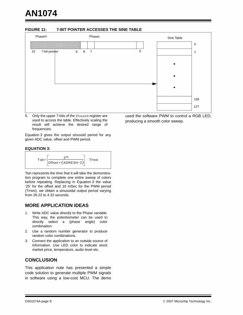
FIGURE 11: 7-BIT POINTER ACCESSES THE SINE TABLE
5. Only the upper 7-bits of the PhaseH register areused to access the table. Effectively scaling theresult will achieve the desired range offrequencies.
Equation 3 gives the output sinusoid period for anygiven ADC value, offset and PWM period.
EQUATION 3:
Tsin represents the time that it will take the demonstra-tion program to complete one entire sweep of colorsbefore repeating. Replacing in Equation 3 the value‘25’ for the offset and 10 mSec for the PWM period(TPWM), we obtain a sinusoidal output period varyingfrom 26.22 to 4.32 seconds.
MORE APPLICATION IDEAS
1. Write ADC value directly to the Phase variable.This way, the potentiometer can be used todirectly select a (phase angle) colorcombination.
2. Use a random number generator to producerandom color combinations.
3. Connect the application to an outside source ofinformation. Use LED color to indicate stockmarket price, temperature, audio level etc.
CONCLUSION
This application note has presented a simplecode solution to generate multiple PWM signalsin software using a low-cost MCU. The demo
used the software PWM to control a RGB LED,producing a smooth color sweep.
Sine TablePhaseH PhaseL
15 7-bit pointer 0
0
127
8 79 1
126
T216
Offset ADRESH 2⁄( )+------------------------------------------------------------------ =sin TPWM⋅
DS01074A-page 8 © 2007 Microchip Technology Inc.

AN1074
REFERENCE
1. AN654: PWM, a Software Solution for thePIC16CXXX (DS00654)
This application note provides a software solu-tion for a more accurate and flexible PWMoutput.
2. AN984: Generating a Sinusoidal Waveform(DS00984)
This application note demonstrates how to mod-ulate a PWM signal to a Sinusoidal waveformand how to generate a three-phase sine wavesignal in software.
3. PIC12F615 Data Sheet (DS41302)
PICKit™ 2 Microcontroller Programmer User’sGuide (DS51553)
© 2007 Microchip Technology Inc. DS01074A-page 9

AN1074
APPENDIX A: THE DEMO CIRCUIT SCHEMATIC
RC
3ı
��
�
��
�
�
�ˇ
�ˇ
��
��
ı
� �ˇ � ��̌ �
1ˇ
+9
- 1
6V
+9
- 1
6V
R1
Z1
C1
R2
R3
VD
D
ICS
PD
AT
ICS
PC
LK
R4
SW
1R
5
VP
P
R6
VD
DU1
C3
7
3 2
8
RB
1
Rg1
Q1
RC
1
RB
2
Rg2
RB
3
Rg3
Q3
Rf1
Rf2
C2
VP
P
VD
D
ICS
PD
AT
ICS
PC
LK
Pro
gra
mm
ing H
eader
1 2 3 4 5 6
PICkit™ Interface
Pow
er
Connecto
r
1 2
PIC12HV615
VD
D
VS
S
GP
0/
AN
0
GP
1/
AN
1
GP
3/
MC
LR
GP
2/
AN
2
GP
4/
AN
3
GP
5/
T1
CK
I
5
D2
D3
RC
2
D1
46
DS01074A-page 10 © 2007 Microchip Technology Inc.

AN1074
APPENDIX B: CIRCUIT EXPLANATION
Description of the tri-color LED demonstration circuitschematic:
When using the PIC12HV615 (featuring an internalshunt regulator) the resistor R1 can be used to reducethe input voltage to 5V. The low pass filter composed byR1C1 reduces the ripples of the input voltage. The Z1Zener diode can be left unpopulated.
On the contrary, if a PIC12F615 or other MCU that doesnot provide a built-in shunt voltage regulator circuit isused, a 5.1V Zener diode (Z1) will be required.
The PIC12HV615 I/O pins can source directly up to 25mA each. In order to drive the LED at a rated current ofapproximately 50 mA, the Q1, Q2 and Q3 transistorsare required.
Resistors Rf1 and Rf2 create a voltage divider circuitwhich provides a feedback path for the DC input volt-age. This voltage feedback could be used to help main-tain a constant LED brightness as the input voltagechanges by changing the PWM duty cycles.
Red, Green and Blue LED emitters have different lumi-nous efficiencies as they do not generate the sameluminous intensity given the same input current. Also,the forward voltage across each LED changes so thatthe amount of current across each LED will be differentgiven the same series resistor value (as in the applica-tion schematic). If a precise matching of the luminousoutput of the three LEDs is required, different collectorresistors RC1, RC2 and RC3 might be required
Alternatively, the same resistor value can be used on allthree diodes and the output intensity can be adjustedmultiplying the duty cycle values of each PWM by anindividual corrective constant in software. The advan-tage of this approach is that it is now possible to cali-brate the color output of the tri-color LED withoutrequiring any hardware modifications. This processcould be automated to be performed at the end of theproduction and testing chain, or in a more advancedapplication, could be performed in a closed control loopprovided a color photo sensor is added as a feedbackelement.
© 2007 Microchip Technology Inc. DS01074A-page 11

AN1074
APPENDIX C: BILL OF MATERIAL FOR THE DEMO
Item Qty Reference Description
1 3 Resistor, RC1, RC2, RC3 320 Ohm, 1 W, SMT 2512
2 1 Resistor, R1 630 Ohm, 1 W, SMT 2512
3 1 Resistor, R2 470 Ohm, 0.25W, SMT 0805
4 2 Resistor, Rf1, R6 10K Ohm, 0.25W, SMT 0805
5 1 Resistor, Rf2 2.7K Ohm, 0.25W, SMT 0805
6 3 Resistor, RB1, RB2, RB3 470 Ohm, 0.25 W, SMT 0805
7 3 Resistor, Rg1, Rg2, Rg3 10K Ohm, 0.25W, SMT 0805
8 1 Resistor, R4 4.7K Ohm, 0.25W, SMT 0805
9 1 Resistor, R5 470 Ohm, 0.25W, SMT 0805
10 1 Resistor Potentiometer, R3 Bourns Series 3386P (Digi-Key 3386P-103-ND)
11 1 Capacitor, C1 25 μF, SMT 3528, Tantalum Capacitor
12 2 Capacitor, C2, C3 0.1 μF, SMT 0805
13 3 Transistor, Q1, Q2, Q3 MMBT3904, SOT23
14 1 Microcontroller PIC12F683/PIC12HV615
15 1 Push Button, SW1
16 1 Zener Diode, Z1 5.1V, 0.5W, SOD-123
17 1 Connector, J2 6 Pin Header, 0.1" Spacing
18 1 Connector, J1 Power Connector, Jack for wall transformer, 2.1 mm (Digi-Key CP-202A)
19 1 Three Color PLCC6 LED OPTEK Technology - OVSTRGBBCR8
DS01074A-page 12 © 2007 Microchip Technology Inc.

AN1074
Software License Agreement
The software supplied herewith by Microchip Technology Incorporated (the “Company”) is intended and supplied to you, theCompany’s customer, for use solely and exclusively with products manufactured by the Company.The software is owned by the Company and/or its supplier, and is protected under applicable copyright laws. All rights are reserved.Any use in violation of the foregoing restrictions may subject the user to criminal sanctions under applicable laws, as well as to civilliability for the breach of the terms and conditions of this license.THIS SOFTWARE IS PROVIDED IN AN “AS IS” CONDITION. NO WARRANTIES, WHETHER EXPRESS, IMPLIED OR STATU-TORY, INCLUDING, BUT NOT LIMITED TO, IMPLIED WARRANTIES OF MERCHANTABILITY AND FITNESS FOR A PARTICU-LAR PURPOSE APPLY TO THIS SOFTWARE. THE COMPANY SHALL NOT, IN ANY CIRCUMSTANCES, BE LIABLE FORSPECIAL, INCIDENTAL OR CONSEQUENTIAL DAMAGES, FOR ANY REASON WHATSOEVER.
APPENDIX D: SOURCE CODE FOR SOFTWARE PWM; File: SoftwarePWM.asm; This file generates 3 software PWM signals using the Timer0 interrupt.; ISR code is provided in this file that should be executed when; a Timer0 interrupt occurs. An initialization routine is also provided; that configures the I/O pins associated with the PWM signals and ; enables Timer0.
list p=12F615 ; list directive to define processor#include <p12F615.inc> ; processor specific variable definitions#include <SoftwarePWM.h>errorlevel -302 ; suppress message 302 from list file
global Dutycycle0, Dutycycle1, Dutycycle2, PWMFlags, InitPWM, ISRPWM, IntCount
UDATAIntCount res 1Dutycycle0 res 1 ; Holds duty cycle for PWM channel 0 Dutycycle1 res 1 ; Holds duty cycle for PWM channel 1Dutycycle2 res 1 ; Holds duty cycle for PWM channel 2w_temp res 1 ; variable used for context savingstatus_temp res 1 ; variable used for context savingpclath_temp res 1 ; variable used for context savingPWMFlags res 1 ; variable used for software flags
CODE
ISRPWMmovwf w_temp ; save off current W register contentsmovf STATUS,w ; move status register into W registermovwf status_temp ; save off contents of STATUS register
; Write TMR0 to setup next interrupt interval movlw .99movwf TMR0
;State Machine for PWM starts from hereDecIntCount ;Decrement IntCount Registerdecfsz IntCount,F ;decrement IntCount register and if it is zero then make the
;output pin highgoto Channel0 ;if IntCount register is not zero then go to chk the dutycycle
;of the signal; If IntCount is 0, then it is time to start a new PWM signal period.BeginPeriod
bsf PWM0 ; Set all PWM output pins highbsf PWM1bsf PWM2
© 2007 Microchip Technology Inc. DS01074A-page 13

AN1074
movlw .32 ; Initialize IntCount to 32movwf IntCountbsf BeginPWM ; Set flag for main software loop
goto ExitISR ; Goto end of ISR code
; If it is not the beginning of the PWM period, we need to compare each ; dutycycle to the value of IntCount. This is done by performing a ; subtraction and checking to see whether the result is 0. When a match; occurs, the output pin for the PWM channel is set to 0.Channel0
movf Dutycycle0,Wsubwf IntCount,WIFNZ ; Is IntCount - DutyCycle0 = 0?goto Channel1bcf PWM0 ; Yes, set output pin to 0.
Channel1movf Dutycycle1,Wsubwf IntCount,W ;Is IntCount - DutyCycle1 = 0?IFNZgoto Channel2bcf PWM1 ;Yes, set output pin to 0
Channel2movf Dutycycle2,Wsubwf IntCount,W ;Is IntCount - DutyCycle2 = 0?IFZbcf PWM2 ;Yes, set output pin to 0
;ISR RestoreDataExitISR
bcf INTCON,T0IF ;clear the T0IF bit in the INTCON registermovf status_temp,w ; retrieve copy of STATUS registermovwf STATUS ; restore pre-isr STATUS register contentsswapf w_temp,fswapf w_temp,w ; restore pre-isr W register contentsretfie ; return from interrupt
;***********************************************************************************************;;InitPWM ;Initialization for software PWM
BANK1 ;Select the RAM memory bank 1
;Timer0 assignmentmovlw b’01000001’ ;Select the internal clock & /4 prescaler
;0------- GPIO Pull-up Enable bit;-1------ Interrupt on rising edge of INT pin;--0----- T0CS->0. Select Timer mode and ; Internal instruction cycle clock (CLKOUT);---0---- T0SE->0. Select falling edge on T0CK1 pin;----0--- PSA->0. Select Timer0 module for Prescaler;-----001 PS2:PS0->001. Select 1:4 Prescaler rate
movwf OPTION_REG ;move the value of work register into OPTION register
;GPIO assignmentmovlw b’00001011’ ;Make GP0, GP1 and GP3 as input and GP2, GP4, GP5 as outputmovwf TRISIO
DS01074A-page 14 © 2007 Microchip Technology Inc.

AN1074
CLRF ANSEL ;Initialize ANSEL register for I/O port
bcf ANSEL,2 ;Digital I/Obcf ANSEL,3
BANK0 ;Select the RAM memory bank 0
CLRF GPIO ;Initialize I/O portclrf CCP1CON
;Interrupts Initializationmovlw b’10100000’ ;Enable global and Timer0 interruptsmovwf INTCON
;Other Variable Initializationmovlw .32movwf IntCount ;Initialize IntCount to 32
;Variables to hold duty cycle valuesmovlw .00movwf Dutycycle0movwf Dutycycle1movwf Dutycycle2
return
END
© 2007 Microchip Technology Inc. DS01074A-page 15

AN1074
APPENDIX E: SOURCE CODE FOR RGB LED DEMO APPLICATION; Filename: Demo.asm; This demo application uses PWM generation software to drive a RGB; LED with a 12F615 device. The PWM code is in SoftwarePWM.asm.; This file initializes the PWM routines and modulates 3 PWM duty; cycles with a sinusoidal profile. The sinusoidal profile causes; the RGB LED to sweep through a range of colors. A potentiometer ; voltage is sampled once per PWM period and the conversion result; is used to set the color sweep speed.
list p=12F615 ; list directive to define processor#include <p12F615.inc> ; processor specific variable definitions#include <SoftwarePWM.h>errorlevel -302 ; suppress message 302 from list file
__CONFIG _CP_OFF & _WDT_OFF & _BOR_ON & _MCLRE_ON & _PWRTE_ON & _INTRC_OSC_NOCLKOUT
#define TABLESIZE .128
UDATATemp res 1PhaseL res 1 ; PhaseL and PhaseH hold the sinusoidal PhaseH res 1 ; pointer location
extern Dutycycle0, Dutycycle1, Dutycycle2, PWMFlags, ISRPWMextern InitPWM, IntCount
;******************************************************************************;;Code starts to run from here;This will placed by the linker inside the memory location bet’n 0 and 4
STARTUP CODE
Reset ;Reset Vector goto Main
nopnopnop
Interrupt ;Interrupt Vector goto ISRPWM ;******************************************************************************;; Main code section starts to run from herePROG CODE ;For the rest of the code
Main
call InitPWM
BANK1 ;Select the RAM memory bank 1
;Configure the input mode of an I/O pin to analog.bsf ANSEL,0 ;Pot input
DS01074A-page 16 © 2007 Microchip Technology Inc.

AN1074
bsf ANSEL,1 ;For bus voltage feedback
; Setup ANSEL bits for ADC clock periodbsf ANSEL,4 ;Clock derived from the internal oscillator bsf ANSEL,5bcf ANSEL,6
BANK0;A/D Module setupmovlw b’00000001’
;0------- ADFM->0: Left justified;-0------ VCFG->0: VDD as Voltage Reference;--00---- Unimplemented bits;----00-- CHS1:CHS0->00: AN0 as Analog channel select;------0- GO/!DONE->0: A/D conversion not in progress or done;-------1 ADON->1: A/D conversion enabled
movwf ADCON0
clrf PhaseH ; Initialize the sinusoidal pointer to 0clrf PhaseL
; The main program loop starts here. The process of PWM signal ; generation is driven by Timer0 interrupts. A software flag; called ‘BeginBWM’ is set in the Timer0 ISR at the start of ; a new PWM period. When the flag is detected in the main loop,; the potentiometer is sampled, the sinusoidal pointer is incremented,; and new duty cycle values are determined for the three PWM signals.MainLoop
btfss BeginPWMgoto MainLoopbcf BeginPWM
ADCConversionbsf ADCON0,GO ;Start A2D conversionbtfsc ADCON0,GO ;Wait until the conversion is completedgoto $-1
; The upper 8 bits of the ADC result is added to the 16-bit sine pointer,; PhaseH:PhaseL. An offset of 25 is also added to make sure the sweep; frequency never goes to 0.
rrf ADRESH,W ; use only the upper 7 bits of ADC resultandwf 0x7f ; mask off upper bit to 0 after rotatemovwf Tempmovlw .25 ;ADRESH + 25addwf Temp,Waddwf PhaseL,F ;PhaseL+Tempbtfsc STATUS,C ;Chk if the Carry is generated because of the
;addition of PhaseL and Temp in the previous ;instruction
incf PhaseH,F
; To get the three duty cycle values, The upper 7 bits of PhaseH are; used as a lookup index to the sine table. Offsets of 0x55 (120; degrees) and 0xAA (240 degrees are used for the 2nd and 3rd duty; cycles.ForPhase1
rrf PhaseH,W andlw 0x7fcall SineTablemovwf Dutycycle0
ForPhase2rrf PhaseH,W addlw 0x55 ;Phase2 = Phase1 + 0x55 for the first phase shift of 120;degree
© 2007 Microchip Technology Inc. DS01074A-page 17

AN1074
andlw 0x7fcall SineTablemovwf Dutycycle1
ForPhase3rrf PhaseH,W addlw 0xAA ;Phase3 = Phase1 + 0xAA for the second phase shift of 240
degreeandlw 0x7fcall SineTablemovwf Dutycycle2
goto MainLoop
; This is a 128 entry table containing 1 cycle of a sine wave.; A 7-bit table index value is required.SineTable
andlw TABLESIZE-1 ;Mask off invalid entriesmovwf Tempmovlw high (TableStart) ;get upper address bits for start of tablemovwf PCLATHmovlw low (TableStart) ;load lower address bits of tableaddwf Temp,w ;add offset.btfsc STATUS,C ;did it overflow?incf PCLATH,f ;yes:increment PCLATHmovwf PCL ;perform a complete jump
TableStartretlw .16retlw .17retlw .17retlw .18retlw .19retlw .20retlw .20retlw .21retlw .22retlw .22retlw .23retlw .24retlw .24retlw .25retlw .26retlw .26retlw .27retlw .27retlw .28retlw .28retlw .28retlw .29retlw .29retlw .30retlw .30retlw .30retlw .30retlw .31retlw .31retlw .31retlw .31retlw .31retlw .31retlw .31retlw .31retlw .31
DS01074A-page 18 © 2007 Microchip Technology Inc.
AN1074
retlw .31retlw .31retlw .30retlw .30retlw .30retlw .30retlw .29retlw .29retlw .28retlw .28retlw .28retlw .27retlw .27retlw .26retlw .26retlw .25retlw .24retlw .24retlw .23retlw .22retlw .22retlw .21retlw .20retlw .20retlw .19retlw .18retlw .17retlw .17retlw .16retlw .15retlw .15retlw .14retlw .13retlw .12retlw .12retlw .11retlw .10retlw .10retlw .09retlw .08retlw .08retlw .07retlw .06retlw .06retlw .05retlw .05retlw .04retlw .04retlw .04retlw .03retlw .03retlw .02retlw .02retlw .02retlw .02retlw .01retlw .01retlw .01retlw .01retlw .01retlw .01retlw .01retlw .01retlw .01retlw .01
© 2007 Microchip Technology Inc. DS01074A-page 19

AN1074
retlw .01retlw .02retlw .02retlw .02retlw .02retlw .03retlw .03retlw .04retlw .04retlw .04retlw .05retlw .05retlw .06retlw .06retlw .07retlw .08retlw .08retlw .09retlw .10retlw .10retlw .11retlw .12retlw .12retlw .13retlw .14retlw .15retlw .15
END
DS01074A-page 20 © 2007 Microchip Technology Inc.

Note the following details of the code protection feature on Microchip devices:
• Microchip products meet the specification contained in their particular Microchip Data Sheet.
• Microchip believes that its family of products is one of the most secure families of its kind on the market today, when used in the intended manner and under normal conditions.
• There are dishonest and possibly illegal methods used to breach the code protection feature. All of these methods, to our knowledge, require using the Microchip products in a manner outside the operating specifications contained in Microchip’s Data Sheets. Most likely, the person doing so is engaged in theft of intellectual property.
• Microchip is willing to work with the customer who is concerned about the integrity of their code.
• Neither Microchip nor any other semiconductor manufacturer can guarantee the security of their code. Code protection does not mean that we are guaranteeing the product as “unbreakable.”
Code protection is constantly evolving. We at Microchip are committed to continuously improving the code protection features of ourproducts. Attempts to break Microchip’s code protection feature may be a violation of the Digital Millennium Copyright Act. If such actsallow unauthorized access to your software or other copyrighted work, you may have a right to sue for relief under that Act.
Information contained in this publication regarding deviceapplications and the like is provided only for your convenienceand may be superseded by updates. It is your responsibility toensure that your application meets with your specifications.MICROCHIP MAKES NO REPRESENTATIONS ORWARRANTIES OF ANY KIND WHETHER EXPRESS ORIMPLIED, WRITTEN OR ORAL, STATUTORY OROTHERWISE, RELATED TO THE INFORMATION,INCLUDING BUT NOT LIMITED TO ITS CONDITION,QUALITY, PERFORMANCE, MERCHANTABILITY ORFITNESS FOR PURPOSE. Microchip disclaims all liabilityarising from this information and its use. Use of Microchipdevices in life support and/or safety applications is entirely atthe buyer’s risk, and the buyer agrees to defend, indemnify andhold harmless Microchip from any and all damages, claims,suits, or expenses resulting from such use. No licenses areconveyed, implicitly or otherwise, under any Microchipintellectual property rights.
© 2007 Microchip Technology Inc.
Trademarks
The Microchip name and logo, the Microchip logo, Accuron, dsPIC, KEELOQ, KEELOQ logo, microID, MPLAB, PIC, PICmicro, PICSTART, PRO MATE, PowerSmart, rfPIC, and SmartShunt are registered trademarks of Microchip Technology Incorporated in the U.S.A. and other countries.
AmpLab, FilterLab, Linear Active Thermistor, Migratable Memory, MXDEV, MXLAB, PS logo, SEEVAL, SmartSensor and The Embedded Control Solutions Company are registered trademarks of Microchip Technology Incorporated in the U.S.A.
Analog-for-the-Digital Age, Application Maestro, CodeGuard, dsPICDEM, dsPICDEM.net, dsPICworks, ECAN, ECONOMONITOR, FanSense, FlexROM, fuzzyLAB, In-Circuit Serial Programming, ICSP, ICEPIC, Mindi, MiWi, MPASM, MPLAB Certified logo, MPLIB, MPLINK, PICkit, PICDEM, PICDEM.net, PICLAB, PICtail, PowerCal, PowerInfo, PowerMate, PowerTool, REAL ICE, rfLAB, rfPICDEM, Select Mode, Smart Serial, SmartTel, Total Endurance, UNI/O, WiperLock and ZENA are trademarks of Microchip Technology Incorporated in the U.S.A. and other countries.
SQTP is a service mark of Microchip Technology Incorporated in the U.S.A.
All other trademarks mentioned herein are property of their respective companies.
© 2007, Microchip Technology Incorporated, Printed in the U.S.A., All Rights Reserved.
Printed on recycled paper.
DS01074A-page 21
Microchip received ISO/TS-16949:2002 certification for its worldwide headquarters, design and wafer fabrication facilities in Chandler and Tempe, Arizona, Gresham, Oregon and Mountain View, California. The Company’s quality system processes and procedures are for its PIC®
MCUs and dsPIC® DSCs, KEELOQ® code hopping devices, Serial EEPROMs, microperipherals, nonvolatile memory and analog products. In addition, Microchip’s quality system for the design and manufacture of development systems is ISO 9001:2000 certified.

DS01074A-page 22 © 2007 Microchip Technology Inc.
AMERICASCorporate Office2355 West Chandler Blvd.Chandler, AZ 85224-6199Tel: 480-792-7200 Fax: 480-792-7277Technical Support: http://support.microchip.comWeb Address: www.microchip.com
AtlantaDuluth, GA Tel: 678-957-9614 Fax: 678-957-1455
BostonWestborough, MA Tel: 774-760-0087 Fax: 774-760-0088
ChicagoItasca, IL Tel: 630-285-0071 Fax: 630-285-0075
DallasAddison, TX Tel: 972-818-7423 Fax: 972-818-2924
DetroitFarmington Hills, MI Tel: 248-538-2250Fax: 248-538-2260
KokomoKokomo, IN Tel: 765-864-8360Fax: 765-864-8387
Los AngelesMission Viejo, CA Tel: 949-462-9523 Fax: 949-462-9608
Santa ClaraSanta Clara, CA Tel: 408-961-6444Fax: 408-961-6445
TorontoMississauga, Ontario, CanadaTel: 905-673-0699 Fax: 905-673-6509
ASIA/PACIFICAsia Pacific OfficeSuites 3707-14, 37th FloorTower 6, The GatewayHabour City, KowloonHong KongTel: 852-2401-1200Fax: 852-2401-3431
Australia - SydneyTel: 61-2-9868-6733Fax: 61-2-9868-6755
China - BeijingTel: 86-10-8528-2100 Fax: 86-10-8528-2104
China - ChengduTel: 86-28-8665-5511Fax: 86-28-8665-7889
China - FuzhouTel: 86-591-8750-3506 Fax: 86-591-8750-3521
China - Hong Kong SARTel: 852-2401-1200 Fax: 852-2401-3431
China - QingdaoTel: 86-532-8502-7355Fax: 86-532-8502-7205
China - ShanghaiTel: 86-21-5407-5533 Fax: 86-21-5407-5066
China - ShenyangTel: 86-24-2334-2829Fax: 86-24-2334-2393
China - ShenzhenTel: 86-755-8203-2660 Fax: 86-755-8203-1760
China - ShundeTel: 86-757-2839-5507 Fax: 86-757-2839-5571
China - WuhanTel: 86-27-5980-5300Fax: 86-27-5980-5118
China - XianTel: 86-29-8833-7250Fax: 86-29-8833-7256
ASIA/PACIFICIndia - BangaloreTel: 91-80-4182-8400 Fax: 91-80-4182-8422
India - New DelhiTel: 91-11-4160-8631Fax: 91-11-4160-8632
India - PuneTel: 91-20-2566-1512Fax: 91-20-2566-1513
Japan - YokohamaTel: 81-45-471- 6166 Fax: 81-45-471-6122
Korea - GumiTel: 82-54-473-4301Fax: 82-54-473-4302
Korea - SeoulTel: 82-2-554-7200Fax: 82-2-558-5932 or 82-2-558-5934
Malaysia - PenangTel: 60-4-646-8870Fax: 60-4-646-5086
Philippines - ManilaTel: 63-2-634-9065Fax: 63-2-634-9069
SingaporeTel: 65-6334-8870Fax: 65-6334-8850
Taiwan - Hsin ChuTel: 886-3-572-9526Fax: 886-3-572-6459
Taiwan - KaohsiungTel: 886-7-536-4818Fax: 886-7-536-4803
Taiwan - TaipeiTel: 886-2-2500-6610 Fax: 886-2-2508-0102
Thailand - BangkokTel: 66-2-694-1351Fax: 66-2-694-1350
EUROPEAustria - WelsTel: 43-7242-2244-39Fax: 43-7242-2244-393Denmark - CopenhagenTel: 45-4450-2828 Fax: 45-4485-2829
France - ParisTel: 33-1-69-53-63-20 Fax: 33-1-69-30-90-79
Germany - MunichTel: 49-89-627-144-0 Fax: 49-89-627-144-44
Italy - Milan Tel: 39-0331-742611 Fax: 39-0331-466781
Netherlands - DrunenTel: 31-416-690399 Fax: 31-416-690340
Spain - MadridTel: 34-91-708-08-90Fax: 34-91-708-08-91
UK - WokinghamTel: 44-118-921-5869Fax: 44-118-921-5820
WORLDWIDE SALES AND SERVICE
12/08/06