Embed Size (px)
Citation preview

Westinghouse Non-Proprietary Class 3
WCAP-16096-NP-A February 2013 Revision 4
Software Program Manual for Common Q™ Systems

WESTINGHOUSE NON-PROPRIETARY CLASS 3
©2013 Westinghouse Electric Company LLC All Rights Reserved
Westinghouse Non-Proprietary Class 3
Nuclear Safety Related
Software Program Manual for Common Q™ Systems
WCAP-16096-NP-A
Rev. 4
February 2013
APPROVALS
Function Name and Signature
Author Matthew A. Shakun* Senior Engineer, Nuclear Automation Licensing
Reviewed Christine P. Scardina-Gazzo* Program Manager, ITAAC
Approved David A. Jarosh* Manager, Independent Verification and Validation II
Stephen L. Packard* Manager, I&C Product Quality
Mark J. Stofko* Manager, Nuclear Automation Licensing
*Electronically approved records are authenticated in the electronic document management system.

Software Program Manual for Common Q™ Systems
WCAP-16096-NP-A, Rev. 4 i Westinghouse Non-Proprietary Class 3
NRC SAFETY EVALUATION – FEBRUARY 7, 2013
This section contains the following documents:
NRC cover letter, “Final Safety Evaluations for Topical Report WCAP-16097, Revision 3,
‘Common Qualified Platform Topical Report,’ (TAC NO. ME5157) and WCAP-16096-P/NP,
‘Software Program Manual for Common Q Systems’ (TAC NO. ME5159)”
“Safety Evaluation by the office of Nuclear Reactor Regulation Westinghouse Topical Report
WCAP-16096-P/NP, Revision 4 ‘Software Program Manual for Common Q Systems’”
LTR-NRC-12-6 NP-Enclosure, “Response to NRC Request for Additional Information on the
Software Program Manual for Common Q Systems (WCAP-16096-P, Rev. 2),” January 2012.

UNITED STATES NUCLEAR REGULATORY COMMISSION
WASHINGTON, D.C. 20555·0001
J. A. Gresham, Manager Regulatory Compliance Westinghouse Electric Company 1000 Westinghouse Drive, Suite 428 Cranberry Township, PA 16066
February 7,2013
SUBJECT: FINAL SAFETY EVALUATIONS FOR TOPICAL REPORT WCAP-16097, REVISION 3, "COMMON QUALIFIED PLATFORM TOPICAL REPORT," (TAC NO.ME5157) AND WCAP-16096-P/NP, "SOFTWARE PROGRAM MANUAL FOR COMMON Q SYSTEMS" (TAC NO. ME5159)
Dear Mr. Gresham:
By letter dated August 26, 2011 (Agencywide Documents Access and Management System (ADAMS) Accession Nos. ML 103220240 and ML 103220086), and supplemented by letters dated March 6, July 17, and July 20 , 2012 (ADAMS Accession Nos. ML 12207A513, ML 12072A289, and ML 12205A051), Westinghouse Electric Company (Westinghouse) submitted WCAP-16097, Revision 3, "Common Qualified Platform Topical Report," and WCAP-16096-P/NP, "Software Program Manual for Common Q Systems" to the U.S. Nuclear Regulatory Commission (NRC) staff for review. By letter dated January 7, 2013, an NRC draft safety evaluation (SE) regarding our approval of WCAP-16096 and WCAP-16097was provided for your review and comment.
By letter dated January 18, 2013, Westinghouse commented on the draft SEs. The NRC staffs disposition of Westinghouse comments on the draft SEs can be found at ADAMS Accession Nos. ML 13029A012 for WCAP-1609 and ML 13028A511 for WCAP-16096.
Based on its review of the information submitted by Westinghouse, the NRC staff finds the topical reports (TRs) acceptable for referencing subject to the limitations specified iri the TRs and in the NRC SEs. The final SEs define the basis for our acceptance of the TR.
Our acceptance applies only to material provided in the subject TRs. We do not intend to repeat our review of the acceptable material described in the TRs. When the TRs appear as references in license applications, our review will ensure that the material presented applies to the specific plant involved. License amendment requests that deviate from these TRs will be subject to a plant-specific review in accordance with applicable review standards.
In accordance with the guidance provided on the NRC website, we request that Westinghouse publish accepted versions of each TR within three months of receipt of this letter. The accepted version shall incorporate this letter and the enclosed final SEs after the title page. Also, the accepted version must contain historical review information, including NRC requests for additional information (RAI) and your responses after the title page. The accepted version shall include an "-A" (designating accepted) following the TR identification symbol.

J.A. Gresham - 2-
As an alternative to including the RAls and RAI responses behind the title page, if changes to the TRs were provided to the NRC staff to support the resolution of RAI responses, and the NRC staff reviewed and approved those changes as described in the RAI responses, there are two ways that the accepted version can capture the RAls:
1. The RAls and RAI responses can be included as an Appendix to the accepted version. 2. The RAls and RAI responses can be captured in the form of a table (inserted after the final SE) which summarizes the changes as shown in the approved version of the TR. The table should reference the specific RAls and RAI responses which resulted in any changes, as shown in the accepted version of the TR.
If future changes to the NRC's regulatory requirements 9ffect the acceptability of these TRs, Westinghouse and/or licensees referencing it will be expected to revise the TRs appropriately, or justify its continued applicability for subsequent referencing.
If you have any questions or need additional information, please feel free to contact the NRC project manager for these TRs, Joe Holonich. Mr. Holonich can be reached at 301-415-7297.
Project No. 280
Enclosure: 1. WCAP-16097 SE 2. WCAP-16096 SE
cc w/encl: Stephanie Smith Westinghouse Electric Company 5000 Ericsson Drive, Suite 517 Warrendale, PA 15086
Sincerely,
Sher 8ahadur, Deputy Director Division of Policy and Rulemaking Office of Nuclear Reactor Regulation

TABLE OF CONTENTS FOR COMMON Q SAFETY EVALUATION
1.0 INTRODUCTION ........................................................................................................... 1 2.0 REGULATORY EVALUATION ...................................................................................... 1 2.1 Regulatory Criteria ................................................................................................... 1 2.2 Method of Review .................................................................................................... 4 2.3 Precedents ............................................................................................................... 5 3.0 TECHNICAL EVALUATION .......................................................................................... 5 3.1 Design Considerations ............................................................................................ 6 3.2 Life Cycle Planning Process for Application Software .............................................. 6 3.2.1 Software Management Plan ............................................................................... 7 3.2.2 Software Development Plan .............................................................................. 8 3.2.3 Software Quality Assurance Plan ....................................................................... 12 3.2.4 Software Integration Plan ................................................................................... 15 3.2.5 Software Installation Plan ................................................................................... 16 3.2.6 Software Maintenance Plan ............................................................................... 17 3.2.7 Software Training Plan ...................................................................................... 17 3.2.8 Software Operations Plan .................................................................................. 18 3.2.9 Software Safety Plan ......................................................................................... 19 3.2.10 Software Verification and Validation Plan .......................................................... 20 3.2.11 Software Configuration Management Plan ......................................................... 24 3.2.12 Software Test Plan (New) ................................................................................... 25 3.2.13 Software Secure Development and Operating Environment Plan ....................... 27 3.2.13.1 Concepts Phase (2.1) ................................................................................ 28 3.2.13.2 Requirements Phase (2.2) ......................................................................... 30 3.2.13.3 Design Phase (2.3) .................................................................................... 32 3.2.13.4 Implementation Phase (2.4) ....................................................................... 34 3.2.13.5 Test Phase (2.5) ........................................................................................ 35 4.0 SUMMARY OF REGULATORY COMPLIANCE EVALUATIONS ................................... 36 4.1 Common Q SPM Generic Change Process .............................................................. 37 4.2 Common Q Record of Changes Document .............................................................. 37 5.0 PLANT-SPECIFIC ACTION ITEMS ................................................................................ 37 6.0 REFERENCES ............................................................................................................... 39 7.0 LIST OF ACRONyMS .................................................................................................... 40

- 1 -
SAFETY EVALUATION FOR WESTINGHOUSE TOPICAL REPORT WCAP-16096-P,
REVISION-4, "SOFTWARE PROGRAM MANUAL FOR COMMON Q SYSTEMS"
TAC NO. ME5159
1.0 INTRODUCTION
Evaluation of the Life Cycle Planning Process for Application Software
The Software Program Manual for Common Q Systems (SPM) was originally submitted as document CE-CES-195-P by Combustion Engineering, for staff review in 2000. This document specifies the life cycle planning process for Common Q application software. The SPM specifies the development, documentation, utilization, and maintenance of software to be developed for use with the Common Q platform in nuclear safety applications. It also provides guidance for the maintenance, implementation, and use of commercial-grade hardware and previously developed software (PDS).
Many changes have been made to the SPM to meet the needs for digital upgrades of existing plants and to address new regulatory requirements. Therefore, the NRC staff reviewed the SPM according to the guidance in Branch Technical Position (BTP) 7-14 Rev. 5, "Guidance on Software Reviews for Digital Computer-Based Instrumentation and Control Systems," which resides in Chapter 7, "Instrumentation and Controls," of NUREG-0800, "Standard Review Plan for the Review of Safety Analysis Reports for Nuclear Power Plants: LWR Edition" (SRP).
In BTP 7-14 the information to be reviewed is subdivided into the following three topic areas:
• Software life cycle process planning; • Software life cycle process implementation; and • Software life cycle process design outputs.
The SPM specifies procedures and controls for the complete software development process. This process includes the integration of software into system hardware. Since the application software has not yet been developed, the NRC staff's evaluation does not include the review of the implementation or outputs of the life cycle process, but is limited to the evaluation of the specified planning processes.
2.0 REGULATORY EVALUATION
2.1 Regulatory Criteria
The following regulatory requirements are applicable to the review of the Common Q SPM:
• 10 CFR 50.55a(a)(1) requires, in part, that systems and components be designed, tested, and inspected to quality standards commensurate with the safety function to be performed.
ENCLOSURE 2
- 2 -
• 10 CFR 50.55a(h), "Protection and Safety Systems," requires compliance with Institute of Electrical and Electronics Engineers (IEEE) Standard (Std) 603-1991, "IEEE Standard Criteria for Safety Systems for Nuclear Power Generating Stations," and the correction dated January 30, 1995.
o Clause 5.3 of IEEE Std 603-1991 requires that components and modules shall be of a quality that is consistent with minimum maintenance requirements and low failure rates. It also requires that safety system equipment be designed, manufactured, inspected, installed, te.sted, operated, and maintained in accordance with a prescribed quality assurance program.
o Clause 5.6.3 of IEEE Std 603-1991 requires safety system to be designed such that credible failures in and consequential actions by other systems will not prevent safety systems from performing their intended safety functions.
o Clause 5.9 of IEEE Std 603-1991 requires the design to permit the administrative control of access to safety system equipment. These administrative controls shall be supported by provisions within the safety systems, by provision in the generating station design, or by a combination thereof.
• 10 CFR Part 50, Appendix A, General Design Criteria (GDC) 1, "Quality Standards and Records," requires, in part, that systems and components important to safety be designed, fabricated, erected, and tested to quality standards commensurate with the importance of the safety functions to be performed.
• 10 CFR Part 50, Appendix A, GDC 21 requires, in part, that protection systems must be designed for high functional reliability commensurate with the safety functions to be performed.
• 10 CFR Part 50, Appendix B, "Quality Assurance Criteria for Nuclear Power Plants and Fuel Processing Plants," Criterion I, "Organization," requires in part that the applicant shall be responsible for the establishment and execution of the quality assurance program.
• 10 CFR Part 50, Appendix B, Criterion II, "Quality Assurance Program," requires in part that the applicant shall establish at the earliest practicable time, consistent with the schedule for accomplishing the activities, a quality assurance program which complies with the requirements of Appendix B.
• 10 CFR Part 50, Appendix B, Criterion III, "Design Control," requires, in part that, for safety-related structures, systems, or components (SSCs), quality standards be specified and that design control measures shall provide for verifying or checking the adequacy of design.
• 10 CFR Part 50, Appendix B, Criterion V, "Instructions, Procedures, and Drawings," requires, in part that, for safety-related SSCs, activities affecting quality shall be prescribed by documented procedures of a type appropriate to the circumstances ....

- 3-
• 10 CFR Part 50, Appendix B, Criterion VI, "Document Control," requires, in part that, for safety-related SSCs, measures shall be established to control the issuance of documents which prescribe all activities affecting quality.
• 10 CFR Part 50, Appendix B, Criterion VII, "Control of Purchased Material and Services," requires documented control of purchased material, equipment, and services for safetyrelated SSCs.
• 10 CFR Part 50, Appendix B, Criterion XI, 'Test Control," requires, in part, that a test program be established to demonstrate that safety-related systems and components will perform satisfactorily in service.
• 10 CFR Part 50, Appendix B, Criterion XV, "Nonconforming Materials, Parts, or Components," requires in part that measures shall be established to control materials, parts, or components which do not conform to requirements in order to prevent their inadvertent use or installation.
The following guidance documents are applicable to, and were utilized in support of, the review of the Common Q SPM.
Regulatory Guides (RGs)
• RG 1.152, Revision 3, "Criteria for Use of Computers in Safety Systems of Nuclear Power Plants."
• RG 1.168, Revision 1, "Verification, Validation, Reviews and Audits for Digital Computer Software Used in Safety Systems of Nuclear Power Plants."
• RG 1.169, "Configuration Management Plans for Digital Computer Software Used in Safety Systems of Nuclear Power Plants," dated September 1997.
• RG 1.170, "Software Test Documentation for Digital Computer Software Used in Safety Systems of Nuclear Power Plants," dated September 1997.
• RG 1.171, "Software Unit Testing for Digital Computer Software Used in Safety Systems of Nuclear Power Plants," dated September 1997.
• RG 1.172, "Software Requirements Specifications for Digital Computer Software Used in Safety Systems of Nuclear Power Plants," dated September 1997.
• RG 1.173, "Developing Software Life Cycle Processes for Digital Computer Software Used in Safety Systems of Nuclear Power Plants," dated September 1997.

-4-
NUREG-Series Publications
• NUREG-0800, "Standard Review Plan for the Review of Safety Analysis Reports for Nuclear Power Plants: LWR Edition," Chapter 7, "Instrumentation and Controls," dated March 2007.
o BTP 7-14, "Guidance on Software Reviews for Digital Computer-Based Instrumentation and Control Systems."
• NUREG/CR 6101, "Software Reliability and Safety in Nuclear Reactor Protection Systems," dated June 1993.
Industry Standards
• IEEE Std 7-4.3.2-2003, "Application Criteria for Programmable Digital Computer Systems in Safety Systems of Nuclear Power Generating Stations," as endorsed by RG 1.152.
• IEEE Std 730-1998, "Software Quality Assurance Plans."
• IEEE Std 828-1990, "Software Configuration Management Plans," as endorsed by RG 1.169.
• IEEE Std 829-1983, "Software Test Documentation," as endorsed by RG 1.170.
• IEEE Std 830-1993, "Guide for Software Requirements Specifications," as endorsed by RG 1.172.
• IEEE Std 1008-1987, "IEEE Standard for Software Unit Testing."
• IEEE Std 1012-1998, "IEEE Standard for Software Verification and Validation Plans," as endorsed by RG 1.168, Revision 1.
• IEEE Std 1028-1997, "IEEE Standard for Software Reviews and Audits," as endorsed by RG 1.168, Revision 1.
• IEEE Std 1042-1987, "IEEE Guide to Software Management," as endorsed by RG 1.169.
• IEEE Std 1063-2001, "IEEE Standard for Software Documentation."
• IEEE Std 1074-1995, "IEEE Std. for Developing Software Life Cycle Processes," as endorsed by RG 1.173.

- 5-
2.2 Method of Review
The NRC staff used the guidance in RGs and BTP 7-14 to review the software life cycle plans outlined in the Common Q SPM.
2.3 Precedents
The NRC previously evaluated the Common Q SPM which was submitted by Westinghouse Electric Company (Westinghouse) as document number WCAP-16096-NP-A Revision 1 (Reference 10). The results of this evaluation are documented in a Safety Evaluation (SE) (Reference 11).
3.0 TECHNICAL EVALUATION
The regulation at 10 CFR Part 50.55a(a)(1) requires, in part, that systems and components be designed, tested, and inspected to quality standards commensurate with the safety function to be performed. Appendix A, "General Design Criteria for Nuclear Power Plants," to 10 CFR Part 50, Criterion 1, "Quality Standards and Records," requires, in part, that a quality assurance program be established and implemented in order to provide adequate assurance that systems and components important to safety will satisfactorily perform their safety functions. The regulation at 10 CFR Part 50, Appendix B, "Quality Assurance Criteria for Nuclear Power Plants and Fuel Reprocessing Plants," describes criteria that a quality assurance program for systems and components that prevent or mitigate the consequences of postulated accidents must meet. In particular, besides the systems and components that directly prevent or mitigate the consequences of postulated accidents, the criteria of Appendix B also apply to all activities affecting the safety-related functions of such systems and components as designing, purchasing, installing, testing, operating, maintaining, or modifying.
BTP 7-14, "Guidance on the Software Reviews for Digital Computer-Based Instrumentation and Control Systems," provides an acceptable way to meet the regulations cited. The NRC staff reviewed the Common Q SPM in accordance with BTP 7-14.
Acceptability of software for safety system functions is dependent upon (1) confirmation that acceptable plans were prepared to control software development activities as described in BTP 7-14, Section B.3.1, (2) evidence that the plans were followed in an acceptable software life cycle as described in BTP 7-14, Section B.3.2, and (3) evidence that the process produced acceptable design outputs as described in BTP 7-14, Section B.3.3. The Common Q SPM only addresses the first item, the planning phase.
This SE instructs applicants referencing Topical Report (TR) WCAP-16096, Revision 4 (Reference 4) to make available specified information. The meaning of the term "make available," however, depends on the type of application referencing the TR, as follows: A licensee requesting amendment of an existing operating license will make available the identified information by including it in the application. An applicant for certification of a standard design will make available the identified information available at the time of presentation of the application or by proposing inspections, tests, analyses and acceptance criteria (ITAAC) that address it. Similarly, an applicant for a combined license (COL) will make available the identified information by providing the necessary information at the time of license

-6-
application or by (1) proposing IT MC that it or by referencing a certified desig n that does so and (2) addressing any remaining COL action items identified in connection with the TR in the design certification. A COL holder will ultimately address the information through the process of closing the associated IT MC if any have been utilized during the licensing process.
BTP 7-14, A.3.1, describes three software planning characteristics: management, implementation, and resource. Management characteristics are significant to the management of the project activities. Implementation characteristics describe the work necessary to achieve the purpose of the planning documents. Resource characteristics describe the material resources necessary to carry out the work defined in the planning document. The Common Q SPM was reviewed against these planning characteristics.
3.1 Design Considerations
The Common Qualified (Common Q) platform is a distributed, microprocessor-based computer system. It is capable of being configured with three or four independent redundant dataprocessing paths or divisions, each with two or three layers of operation, Data processing paths can be run asynchronous with respect to each other. Layers of operation include signal acquisition, data-processing, and actuation signal voting. The Common Q platform uses microprocessor-based digital equipment, operating system software, and plant-specific application software to perform safety-related instrumentation & control (I&C) system functions at nuclear power plants. A full description of the Common Q platform may be found in the Common Q platform TR (Reference 2).
Application software is developed for project-specific applications of the Common Q platform. Software implements plant-specific I&C and logic functions, and is hardware dependent. Software will be developed using the Asea Brown Boveri (ABB) Master Programming Language Control Configuration (ACC) and Photon software development tools. The Common Q SPM describes the conditions and objectives to develop application software.
3.2 Life Cycle Planning Process for Application Software
Digitall&C safety systems must be designed, fabricated, installed, and tested to quality standards commensurate with the level of the importance of the safety functions to be performed. The development of safety system software should progress according to a formally defined software lifecycle (SLC). Implementation of an acceptable SLC provides reasonable assurance the necessary software quality has been instilled in the final system. BTP 7-14, Section B.2.1, states that the information to be reviewed for the software life cycle process planning should be found under the following topics:
B.3.1.1 B.3.1.2 B.3.1.3 B.3.1.4 B.3.1.5 B.3.1.6 B.3.1.7 B.3.1.8 B.3.1.9
Software Management Plan Software Development Plan Software Quality Assurance Plan Software Integration Plan Software Installation Plan Software Maintenance Plan Software Training Plan Software Operations Plan Software Safety Plan

- 7 -
B.3.1.10 B.3.1.11 B.3.1.12
Software Verification and Validation Plan Software Configuration Management Plan Software Test Plan
In addition, Westinghouse has developed a separate Secure Development and Operating Environment (SDOE) plan to address the criteria of RG 1.152 which provides guidance for the establishment of a SDOE for safety related software.
While most of the information about the above topics is in the SPM, information found in the other submittals is sometimes helpful to the evaluation, and is considered. The SPM includes sections with the following section numbers and titles:
3. Software Safety Plan (SSP) 4. Software Quality Assurance Plan (SQAP) 5. Software Verification and Validation Plan (SWP) 6. Software Configuration Management Plan (SCMP) 7. Software Test Plan (STP) 8. Software Maintenance Plan (SMP)
The staff found the information needed to support its safety conclusions on the balance of the life cycle topics either in the balance of the SPM or in the Common Q TR WCAP-16097 -P, Revision 3, "Common Qualified Platform" (Reference 2) and its appendices. The NRC staff has organized this report to follow the sequence outlined under the topic in BTP 7-14. BTP 7-14, Section B.3.1, describes the acceptance criteria used for reviewing the 12 software plans of the SPM.
3.2.1 Software Management Plan
The software management plan describes the management aspects of the software development project. BTP 7-14, Section B.3.1.1, describes acceptance criteria for software management plans. RG 1.173 endorses IEEE Std 1074-1995, "IEEE Standard for Developing Software Life Cycle Processes." IEEE Std 1074-1995 describes, in terms of inputs and outputs, a set of processes and constituent activities that are commonly accepted as comprising a controlled and well coordinated software development process. IEEE Std 1074-1995 Chapter 3, "Project Management Process," describes an acceptable approach for software project management. It states that project management processes are, "the processes that initiate, monitor, and control software projects throughout the software life cycle."
The required elements of a Software Management Plan are contained within Sections 2, 4.3, 5.5.1, and 6.2 of the Common Q SPM. These sections of the SPM define a strategy for managing Common Q software projects. Each of these sections was reviewed against the specific acceptance criteria established by BTP 7-14.
Section 4.3 of the Common Q SPM describes the management principles used for the development of Common Q application software for each phase of the software development life cycle. It includes a description of the software project planning organization which includes a general overview of the organizational structure used by Westinghouse and a discussion of the responsibilities that each of the following organizations has within the process.

- 8 -
o Nuclear Automation Organization • Ouality Organization • Engineering Organization
• Design Team • V&VTeam
The specific tasks and responsibilities performed by these organizations during each of the software Iifecycle phases are described within the SPM. These tasks include software design and development, software quality assurance planning, verification reviews, audits, test planning, test execution, and test reporting. The SPM describes the interfaces and boundaries that exist between these organizations.
A level of independence between the Verification and Validation (V&V) team and the design team is established by specifying different reporting structures within the Engineering organization. The directors to which the V&V team and the design team report are administratively and financially independent of one another. This relationship between the design team and the independent verification and validation (lW) team is illustrated in Exhibit 2-1 of the SPM. The degree of independence between the V&V team and the design team is further reinforced by not allowing V&V team members to participate on the design team.
The SPM calls for the development of a project specific Project Ouality Plan (POP) during the Initiation (Concepts) Phase of the software development life cycle. The POP allows for alternatives to the SPM processes. Because of this, the POP should be reviewed to determine if the justification for the use of alternatives to the SPM or other, additional metrics or qualifiers beyond the directions within the SPM is acceptable when an applicant requests approval for installation of a safety-related system based on the Common 0 platform. This is plant specific action item 1.
Per BTP 7-14, Sections B.3.2 and B.3.3, the implementation activities and design outputs are to be separately evaluated so that the application design can be evaluated to determine that the software management plan has been followed. This is plant specific action item 2.
The elements of the software management plan are incorporated into the Common 0 SPM. The NRC staff has reviewed the Common 0 SPM and finds that it establishes adequate organization and authority structure for the design, the procedures to be used, and the relationships between major activities. The NRC staff finds that the management structure in the Common 0 SPM provides for adequate project oversight, control, reporting, review, and assessment. The NRC staff concludes that the Common 0 SPM meets the requirements for a software management plan as outlined in IEEE Std 1074-1995 as endorsed by RG. 1.173 and is, therefore, acceptable.
3.2.2 Software Development Plan
The SDP describes the plan for technical project development. BTP 7-14, Section B.3.1.2 describes acceptance criteria for software development plans. RG 1.173 endorses IEEE Std 1074-1995 as providing an acceptable approach to software development processes. BTP 7-14 states that the SDP should clearly state tasks of each life cycle, and state the life cycle inputs and outputs. The review, verification and validation of those outputs should be

- 9 -
defined. IEEE Std 7-4.3.2-2003 provides additional guidance on software development processes.
Westinghouse utilizes a controlled software development process which is defined within the Common Q SPM. The criteria for the Common Q SOP are satisfied by a project plan and a Project Quality Plan. These plans are created for each Common Q project in accordance with general criteria that is defined within the SMP. The required elements of a SOP are defined within the following SPM sections:
• 1.4.1, "Software Life Cycle" • 1.2.1, "Software Classification and Categorization" • 4.1.3, "Software Development Process" • 5.9, "Software Integrity Level Scheme"
Common Q Software Life Cycle
Section 1.4.1 of the SPM defines the SLC used for the development of Common Q software. This life cycle is consistent with a classic waterfall model like the model discussed in Section 2.3.1 of NUREG/CR-61 01. The Common Q SLC consists of the following life cycle phases:
1. Concept 2. Requirements Analysis 3. Design 4. Implementation or Coding 5. Test 6. Installation and Checkout 7. Operation and Maintenance 8. Retirement
This model assumes that each phase of the lifecycle is completed in sequential order from concept to the retirement phase. The staff finds the Westinghouse choice of SLC acceptable since the waterfall model is well suited for projects with known and stable requirements and where few changes to requirements are anticipated. Since Westinghouse selected an acceptable software life cycle model, the guidance criteria of IEEE Std 1074-1995, Clause 2.4 has been satisfied.
Common Q Software Life Cycle Tasks (Inputs & Outputs)
BTP 7-14, Section B.3.1.2.4, states that an applicant should identify which tasks are included with each life cycle phase, and state the life cycle inputs and outputs. Exhibit 4-3 of the SPM identifies tasks which are performed for various software categories during the SLC process and identifies the phases during which each task is performed. In addition, Exhibit 5-1 of the SPM defines the responsibilities for completion of software tasks.
Note: For Exhibits 4-3 and 5-1, Westinghouse has grouped individual tasks into general category headings. For example the task "Design Verification" may in fact include several individual subtasks that are not listed in Exhibit 5-1. As such, specific individual V&V tasks are
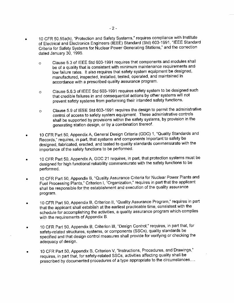
- 10-
not delineated in these tables. Exhibit 5-8 was created in conjunction with Section 5 of the SPM to list and define the specific V&V tasks and to map these tasks to the V&V activities defined within IEEE Std 1012-1998. IEEE Std 1012-1998, Clause 1.6 states that the mapping of the software integrity level scheme and the associated minimum V&V tasks shall be documented in the Software Verification and Validation Plan. In response to requests for additional information items 6 and 7 (References 12 and 13), Westinghouse added Exhibit 5-8, Attachment A to the SPM. This exhibit contains a mapping of the V&V activities associated with the development lifecycle of a Common Q system to the IEEE Std 1012-1998 standard. This mapping table also identifies the phase of the development lifecycle in which each activity is performed. In many cases, V&V activities are performed several times during the development process. The left-hand column of this table lists all of the V&V activities from Table 2 of IEEE Std 1012-1998. Each of these activities has a corresponding activity and reference to the SPM section for the equivalent activity within the Common Q development process. The NRC staff reviewed the activities included in this mapping table and determined that it contains sufficient detail and reference to the SPM to show that the V&V activities performed for safety related Common Q application Protection software are consistent with high criticality software developed to SIL Level 4 as defined by IEEE Std 1012-1998 and is therefore acceptable.
Common Q Software Integrity Scheme
Section 5.9 of the Common Q SPM discusses the Westinghouse software classification or software integrity level scheme. Table 5.9.1 of the SPM compares the Westinghouse software integrity scheme with the scheme presented within IEEE Std 1012-1998. IEEE Std 1012-1998 states that "Software integrity levels denote a range of software criticality values necessary to maintain risks within acceptable limits." Section 1.2.1 of the SPM defines the software classes used for Common Q software as follows:
• Protection (safety critical). Software whose function is necessary to directly perfonn RPS control actions, ESF AS control actions, and safe shutdown control actions.
• Important-to-Safety. Software whose function is necessary to directly perfonn alternate protection system control actions or software that is relied on to monitor or test protection functions, or software that monitors plant critical safety functions.
• Important-to-Availability. Software that is relied on to maintain operation of plant systems and equipment that are critical to maintaining an operating plant.
• General Purpose. Software that performs some purpose other than that described in the previous classifications. This software includes tools that are used to develop software in the other classifications, but is not installed in the online plant system. Examples of General Purpose software include commercial grade dedication test software, compilers, assemblers, linkers, comparators, editors, test case generators, and test coverage analyzers.
Exhibit 4-1 of the SPM identifies assignment of Common Q components to the software classes described above. All Common Q application software on the Advant Controller 160 (AC160) safety processors, the Operator Modules (OMs) and the Maintenance and Test Panels (MTPs)

- 11 -
are classified as either Protection or Important to Safety. This is consistent with the fact that Common Q system is classified as Class 1 E as defined by IEEE Std. 603-1991.
Common Q components and software that are classified as either Protection or Important to Safety are considered to be safety related. It is however, understood that the subset of safety related software that is classified as Important to Safety does not directly perform RPS or ESFAS safety functions. For this reason, it is acceptable for Important to Safety software to be developed using V&V activities that are not equivalent to SIL Level 4 activities as defined in IEEE Std 1012-1998.
The NRC staff finds the software integrity level scheme used for the Common Q platform and application development acceptable since it is similar to the software integrity scheme defined in IEEE Std 1012 1998, and because the scheme is appropriately used to establish a minimum set of V&V tasks. Section 3.2.10 of this SE provides additional evaluation of the V&V tasks performed on Common Q software.
Management and Oversight of the Software Development Processes
The project manager is responsible for ensuring that the design, verification and validation, and quality assurance (QA) activities are conducted in accordance with the SPM. The corrective action program used during the Common Q development process is defined in Section 11 of the SPM. This program is designed to promptly identify and correct conditions adverse to safety and quality. This program provides oversight to ensure that development process will be followed and any deviation will be discovered in time to take corrective action.
Software Tools
BTP 7-14, Section B.3.1.2.4, provides guidance for software tools, and references IEEE Std 7-4.3.2-2003, Clause 5.3.2, which states, in part, that software tools used to support software development processes and verification and validation processes shall be controlled under configuration management. To confirm the software tools are suitable for use, the clause further states either a test tool validation program shall be developed to provide confidence that the necessary features of the software tool function as intended or the software tool shall be used in a manner such that defects not detected by the software tool will be detected by V&V activities.
The Common Q SPM, Sections 3.3.10 and 4.9, discuss the development support tools used to facilitate Common Q application software development. An evaluation of a tool's readiness for use on a project is performed before such a tool is used to support the development of a Common Q application. This evaluation considers: the tool's past performance, extent of tool validation performed, consistency of tool design with planned use, use of tool upgrades, retirement of the tool, and restrictions on the use of the tool due to its limitations. The configuration management, software QA and IW processes defined within the SPM apply to software tools and provide a means of ensuring that these tools are only used for their approved and intended purposes. The outputs of software tools undergo the V&V process as defined in the SWP, in SPM Section 5.
The NRC staff has reviewed the Common Q SPM and concludes that the software development plan conforms with the criteria provided by IEEE Std. 1074-1995, "IEEE Standard for
- 12 -
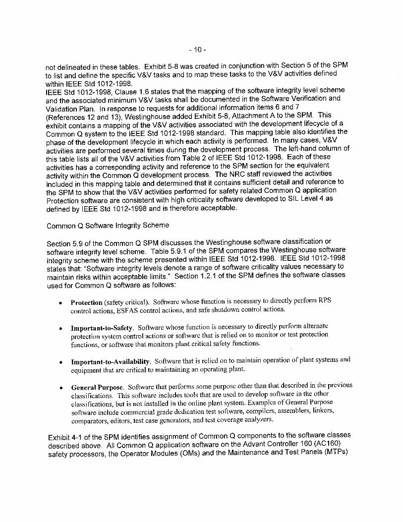
Developing Software Life Cycle Processes," as endorsed by RG 1.173, "Developing Software Life Cycle Processes for Digital Computer Software Used in Safety Systems of Nuclear Power Plants." In addition, the SPM adequately addresses the software development planning activities of BTP 7-14. The SPM describes acceptable methods of organizing the software life cycle. The NRC staff, therefore, concludes that Westinghouse's application software development plan is acceptable.
3.2.3 Software Quality Assurance Plan
BTP 7-14, Section B.3.1.3, provides guidance in evaluating a SQAP. The SQAP shall conform to the requirements of 10 CFR Part 50, Appendix B, and the applicant's overall QA program. The regulation at 10 CFR Part 50, Appendix B states that the applicant shall be responsible for the establishment and execution of the QA program. The applicant may delegate the work of establishing and executing the QA program, or any part thereof, but shall retain responsibility for the QA program. The SQAP would typically identify which QA procedures are applicable to specific software processes, identify particular methods chosen to implement QA procedural requirements, and augment and supplement the QA program as needed for software.
IEEE Std. 7-4.3.2-2003, Clause 5.3.1, which is endorsed by RG 1.152 provides guidance on software quality assurance. IEEE Std.7-4.3.2-2003, Clause 5.3.1, states, "Computer software shall be developed, modified, or accepted in accordance with an approved software QA plan.
The Common Q SQAP for application software is described in Section 4 of the SPM, "Software Quality Assurance Plan." The SQAP describes the methodology used for managing Common Q software throughout the development life cycle. Section 4.1.1 of the SPM states that the Common Q SPM complies with IEEE Std 730-1998. The scope of the Common Q SQAP includes software in all four SIL classifications; protection, important to safety, important to availability, and general purpose. The Common Q SQAP applies to original software that was developed under the requirements of the Common Q SPM.
Evaluations of existing software not created under the controls of the Common Q SPM are performed in order to qualify this software for use under the Common Q SPM. For commercial software, qualification is achieved through the use of Westinghouse's commercial grade dedication program. For non-commercial software that has actively been used in a nuclear power plant being implemented in Common Q, an evaluation is performed to ensure the quality assurance program being used for development and maintenance of this software is acceptable and includes the following:
• The effective QA program has an active program for problem and corrective action reporting.
• The software has adequate design documentation. • The software has adequate user documentation. • The software includes well commented source code. • The software has been verified and validated under a program that the IW team
determines to be appropriate.

- 13-
For non-commercial software that has not been actively used in a nuclear power plant being implemented in Common Q, an evaluation is performed to ensure that appropriate quality controls commensurate with the safety classification of the software are implemented.
Quality assurance tasks are listed in Exhibit 4-3 of the SPM. These QA tasks are described in Section 4 of the SPM for each software life cycle phase. These descriptions include a discussion of the tasks and the responsibilities of the organizations performing software QA activities. In addition, Exhibit 5-1 identifies organizational responsibilities for performance of specific software QA (SQA) tasks.
Documentation requirements for performance of SQA activities are described in Section 4.4, "Documentation," of the SMP. Many of the tasks listed in Exhibit 4-3 are in fact documents that will provide evidence for completion of the associated SQA tasks. Furthermore, Section 10 of the SPM, "Documentation," provides guidance for how these documents will be developed.
SPM Section 4.5 identifies the standards, practices, conventions and metrics used for the development of a Common Q based system. It states that, "compliance with the WEC quality management system standards shall be monitored and assured through the review and audit process." Standards used for development of Common Q systems include Coding Standards, Software Testing Standards, and Documentation Standards. Coding standards are not established at a generic level and are instead defined within the project specific PQP. Testing standards are defined by the Software Test Plan which is evaluated in Section 3.2.12 of this SE. Documentation Standards are identified in Section 10 of the SPM and include IEEE Std 830-1998 for Software Requirement Specification (SRS) documentation requirements, IEEE Std 1016-1998 for Software Design Description (SDD) documentation requirements, IEEE Std 1012-1998 forV&V documentation requirements, and IEEE Std 1063-2001 for software user documentation requirements.
SPM Section 4.6 describes how software reviews are performed for Common Q applications. Software reviews are performed to verify technical adequacy and to verify completeness of the design and development of Common Q software. The SPM lists several software review activities and defines groups responsible for performance of these activities. The following types of reviews which are defined in IEEE Std 1028-1997 are performed for Common Q software developed under the SPM:
• Management Reviews, • Technical Reviews, • Inspections, • Walk-throughs, and • Audits.
SPM Section 4.6.2 describes the minimum software reviews and audits to be performed for Common Q software. The NRC staff has determined that this minimum set of review and audit requirements complies with the criteria of IEEE Std 730-1998 Sections 4.6.2.1 through 4.6.2.10.
IEEE Std 730-1998, Section 4.8 states that the SQAP should describe practices and procedures to be followed for reporting, tracking, and resolving problems. It also stipulates that the SQAP should state specific organizational responsibilities concerned with implementation. The

- 14-
Common 0 SPM Section 11, "Problem Reporting and Corrective Actions," discusses the Common 0 processes relating to these criteria. The SPM describes the problem reporting process used to handle discrepancies, deficiencies, or comments identified as a result of testing, review, or other means. The SPM describes two processes used for reporting errors. One is used for errors identified during the development process prior to approval for use in a nuclear power plant application and the other is used for reporting of errors that are identified after the software has been approved for use. These processes include noncompliance reporting in accordance with 10 CFR Part 21, "Reporting of Defects and Noncompliance." Organizational responsibilities associated with the problem reporting and corrective action processes are also defined.
The Common 0 SPM Section 11.4 describes the corrective action program, which is used to resolve all validation test problems, verification review comments, and other reported errors.
During the Initiation (Concept) phase, the SOAP calls for the development of a POP which becomes the operative plan for a specific application development process. This POP may deviate from the SOAP processes defined in Section 4 of the SPM; however, any such deviations must be documented and justified within the POP. Because such deviations cannot be evaluated during this safety evaluation, a plant specific action item for evaluating these changes has been created. This is plant specific action item 1.
The regulation at 10 CFR Part 50, Appendix B, allows applicants or licensees to delegate the work of establishing and executing the OA program, but applicants/licensees shall retain overall responsibility and shall determine if the quality of the software is sufficient. Applicants or licensees referencing this TR are to make available a SOAP to address these licensee specific responsibilities. This is plant specific action item 3.
The SOAP stipulates that the SOA organization shall participate in formal reviews and audits of the software development activity. Required reviews and audits are indicated in the plan including review documentation requirements, evaluation criteria, anomaly reporting, and anomaly resolution procedures. Additional reporting of the NRC staff's evaluation of the SOAP is detailed in Section 3.2.10, "Software Verification and Validation Plan."
The SOAP describes the process by which Westinghouse manages software and documentation throughout the Common 0 software development life cycle, and the SOAP conforms to I EEE Std. 730-1998. The Engineering Project Manager is responsible for ensuring all design team activities are performed in accordance with the OA processes and procedures. The SOAP adequately addresses the software quality planning activities of BTP 7-14. The NRC staff concludes that the Common 0 SOAP meets the Guidance in BTP 7-14 Section B.3.1.3 with regard to OA software reviews and audits and is, therefore, acceptable.
3.2.4 Software Integration Plan
BTP 7-14, Section B.3.1.4, provides guidance in evaluating a Software Integration Plan (SlntP). IEEE Std 1074-1995, Clause 5.3.7, which is endorsed by RG 1.173, provides an acceptable approach to an integration plan. Clause 5.3.7 states that during the plan integration activity, the software requirements and the software design description are analyzed to determine the order of combining software components into an overall system. In addition, Clause 5.3.7 states that the integration planned information shall be coordinated with the test planned information as
- 15 -
described in IEEE Std 1074-1995, Clause 7.1. BTP 7-14, Section B.3.1.4.1, asks for a description of the software integration process and the software integration organization.
Westinghouse does not define a separate software integration organization to perform system integration related activities. Instead, such activities are allocated to different organizations involved with the Common Q software development processes. This allocation of integration activities is defined within various sections within the SMP. For example, integration tests are defined in Section 7.3.1.3 of the SPM and Exhibit 5-1 show that the IW team has the responsibility for performing integration tests for protection software.
The testing aspects of Common Q Software Integration are described in Section 7 of the SPM. The Common Q software testing process includes Integration Tests that are conducted on the target hardware that is assembled in either a cabinet or single channel configuration for shipment to the customer. Section 7.3.1.3 describes the details of the integration tests performed during the development of a Common Q application. Section 4.5.2.4 of the SPM discusses metrics used for integration tests.
The Common Q system is an integrated suite of hardware and software designed specifically for nuclear safety applications. Software integration of an application that uses Common Q consists of three components.
1. Integration of software modules to form system executable programs. For a Common Q project this level of integration is accomplished by the creation of control functions using the ACC development tool. Proper use of ACC involves assembly of pre-approved Program Control (PC) elements into complete control functions. These control functions are converted into code to be used for transfer to the Common Q hardware. Structured design techniques, including the use of data flow diagrams, represent interactions among modular elements and the flow of data among these elements. Unit and module tests are performed to ensure that the module and system requirements have been met by the integrated software.
Software used in the FPDS system is developed in accordance with the SPM processes. FPDS software applications are developed using the photon graphical user interface software tool. Structured design techniques similar to those used for AC160 are also applied to the development processes of the FPDS components. These FPDS applications are then integrated into the FPDS node box and the FPDS hardware is integrated into the application specific Common Q system design.
2. Integration of the resultant programs with the hardware and instrumentation. This level of integration is performed at the manufacturing facility after the cabinets are assembled and energized. The system hardware architecture is established in conjunction with the application software using the ACC tool; therefore, specific assignment of software programs to PM646A processors is performed prior to the generation of application executable code. The processor applications are loaded into the PM646A processors as the system is prepared for integration testing. An integration test is performed to verify that the released software correctly integrated with the production hardware. All cabinets within a safety system division are interconnected and integrated as a part of the integration test process.

- 16-
3. Testing the resulting integrated product. This final level of integration is completed during the system FAT by confirming the correct relationship between test input and output signals. System functions that are implemented across multiple safety divisions are tested to ensure that the overall integrated system meets the systems specifications defined in the SRS. The FAT verifies that all system level functional and performance requirements are satisfied. All cabinets in the safety system are included in the FAT.
The NRC staff reviewed Westinghouse's application software development and testing processes for both AC 160 and FPD software and found they specify how to develop plans for software integration both during the development of the software and during integration with the hardware. The actual integration procedures will be prepared during the planning stage of each project. The NRC staff concludes that the plans for software integration exhibit the management, implementation, and resource characteristics outlined in BTP 7-14 and are, therefore, acceptable.
3.2.5 Software Installation Plan
The acceptance criteria for a Software Installation Plan are contained in BTP 7-14, Section B.3.1.5. IEEE Std 1074-1995, Clause 6.1, endorsed by RG 1.173, provides an acceptable approach for software installation plans. IEEE Std 1074-1995, Clause 6.1.1 states an installation consists of the transportation and installation of the software system from the development environment to the target environment. It includes the necessary software modifications, checkout in the target environment, and customer acceptance. If a problem arises, it must be identified and reported. BTP 7-14, Section B.3.1.5.4, states that there should be approved procedures for software installation, for combined hardware and software installation, and systems installation. In addition there should be a controlled process to identify, correct, and document errors in the installation procedures.
The Software Installation Plan for Common Q system software is Section 8 of the Common Q SPM. Its purpose is to describe the installation processes to be used for the Common Q system. These processes include loading both operating system and application software into the Common Q AC160 processor modules and into the FPD system processors.
The NRC staff reviewed the Common Q SPM and found that it included adequate plans for software installation. The procedure(s) for installing the software will be prepared before the installation and checkout phase of the software life cycle. The NRC staff finds that the plans for software installation exhibit the management, implementation, and resource characteristics outlined in BTP 7-14 and are, therefore, acceptable. However, the Common Q Software Installation Plan does not address the installation of the Common Q System into the plant environment. Since the applicant or licensee assumes responsibility, including vendor oversight, for the software installation phase information necessary to address the criteria of BTP 7-14, further evaluation of the site installation activities will be required. This should be accomplished as part of plant specific action item 2.
3.2.6 Software Maintenance Plan
The acceptance criteria for a Software Maintenance Plan are contained in BTP 7-14. Section B.3.1.6. IEEE Std 7-4.3.2-2003, Clause 5.4.2.3, endorsed by RG 1.152 provides guidance on maintenance and configuration management for commercially dedicated items.

- 17 -
IEEE Std 1074-1995, Clause 6.3, endorsed by RG 1.173, provides an acceptable approach for software maintenance plans. IEEE Std 1074-1995, Clause 6.3.1 states a maintenance process is concerned with the resolution of software errors, faults, and failures; that the need for software maintenance initiates software life cycle changes. NUREG/CR-61 01, Section 3.1.9 and Section 4.1.9 also contain guidance on SMPs. These sections identify the maintenance activities to be governed by the SMP as; failure reporting, fault correction, and re-release procedures.
The SMP for Common Q system software is Section 9 of the Common Q Software Program Manual. This plan specifies the requirements for the maintenance and use of Protection class and Important-to-Safety class software used in Common Q Systems. Activities associated with the maintenance phase include:
1. Problem/modification identification, classification, and prioritization; 2. Problem analysis; 3. Solution design; 4. Solution implementation; 5. Solution/system test; and 6. Delivery.
The NRC staff has reviewed the plan for maintenance of the software as described in the SPM and concludes that it exhibits the characteristics for management, implementation, and resources as set forth in BTP 7-14 and is, therefore, acceptable.
3.2.7 Software Training Plan
The acceptance criteria for a Software Training Plan are contained in BTP 7-14, Section B.3.1.7. IEEE Std 1074-1995, Clause 7.4, endorsed by RG 1.173, provides an acceptable approach to software training plans. IEEE Std 1074-1995, Clause 7.4.2 lists typical activities for this software life cycle activity: plan the training program, develop training materials, validate the training program, and implement the training program. If the licensee will be performing the digital system maintenance, the training plan(s) will be more involved, since additional knowledge is necessary to perform maintenance.
Personnel involved in Common Q software design and development are required to have documented training in material covered by the SPM. The requirements for training associated with the Common Q system are addressed within the following sections of the SPM:
• 3.3.3, "Staff Qualifications and Training" • 3.5.1, 'Training" • 4.14, "Training" • 7.2.2, "Staffing and Training"
In addition requirements for maintaining Training Materials and Training Records are listed in Table 1, "Document Requirements" and Table 2, "Information Requirements," for the Common Q system.

- 18 -
The Common Q SPM specifies the requirements for training programs for end users. Common Q customers are responsible for providing safety training for the users, operators, and maintenance and management personnel. All training materials prepared for Common Q customers must be reviewed by the IW team. For each software system, a separate training program will be developed to ensure safe operation and use of the software within the overall system. The training program will include safety training for the users, operators, and maintenance and management personnel, as appropriate. The SPM stipulates that a training record will be kept on file for each training session, recording the instructor, date, material covered, and personnel attending, to ensure that the appropriate training has been obtained before using the system. The V&V team will review the training documentation for traceability to safety requirements. The training programs for use at the sites will be developed later. This is an activity that will be influenced by the end users' training facilities and procedures. The NRR staff concludes that the specified plans for training of the software developers and end users meet the criteria outlined in BTP 7-14 and are, therefore, acceptable.
3.2.8 Software Operations Plan
The acceptance criteria for a Software Operations Plan are contained in BTP 7-14, Section B.3.1.8. IEEE Std 1074-1995, Clause 6.2, endorsed by RG 1.173, provides guidance for software operations plans. IEEE Std 1074-1995, Clause 6.2.1 states an operation and support process involves user operation of the system and ongoing support. Support includes providing technical assistance, consulting with the user, and recording user support requests by maintaining a Support Request Log. Thus, the Operation and Support Process may trigger Maintenance Activities, which the SMP should address. IEEE Std 1074-1995, Clause 6.2.3.2 states that the installed software system shall be utilized in the intended environment and in accordance with the operating instructions.
During the previous Common Q SE both the operation and the maintenance phases of the software life cycle were addressed in SPM Section 7, "Software Operation and Maintenance Plan." In the revised version of the SPM, this section, which is now Section 9, has been re-titled as the "Software Maintenance Plan," and there is no longer a dedicated section in the SPM to address the criteria for software operations planning. Westinghouse stated that the Software Operations Plan is either a project specific activity or the Licensee's responsibility.
The Software Operations Plan is not within the scope of the Common Q SPM. Therefore, a safety determination cannot be made for a Software Operations Plan in this regard. Since the applicant or licensee will assume responsibility, including vendor oversight, for the software operations phase of the software life cycle, relevant information must be evaluated as part of a plant specific action item. An evaluation of compliance with the criteria of BTP 7-14 Section B. 3.1. 8 shall be performed at the time of system development when the operational aspects of the system have been defined. These requirements are captured as PSAls 3 and 4.
3.2.9 Software Safety Plan
BTP 7-14, Section B.3.1.9, provides guidance to evaluate software safety plans (SSP). The SSP should provide appropriate safety measures in the software requirements specification. The SSP should define the safety-related activities to be carried out for each set of life cycle activities, from requirements through operation and maintenance. The SSP should describe the boundaries and interfaces between the software safety organization and others. It should show

- 19 -
how the software safety activities are coordinated with the development activities and the interactions between software safety organization and the software V&V organization. SSP should designate a single safety officer who has clear responsibility for the safety qualities and has clear authority to accomplish the goals of the safety requirements in the SRS design, and implementation of the software.
The Software Safety Plan for Common Q system software is Section 3 of the Common Q Software Program Manual. The stated purpose of the Common Q Software Safety Plan is, " ... to enable the development of safety critical software for Common Q Systems that has reasonable assurance that software defects do not present severe consequences to public health and safety."
To accomplish this goal, the Common Q SSP defines procedures and methodologies to be used for the development, procurement, maintenance and ultimately, retirement of all Protection class Common Q software. The other classes of Common Q software; Important to Safety, Important to Availability, and General Purpose, are not included in the SSP because they are not considered to be safety critical. This is because the failure of this software would not result in severe consequences to public health and safety.
Software Safety Organization
The Common Q SSP establishes a software safety organization which is composed of two parts. The first part is the quality organization, which is an independent QA department. This quality organization coordinates and reviews QA procedures and directives. The Quality organization has a reporting chain separate from the design team such that the QA organization is independent of project schedule and cost considerations. The quality organization provides oversight by way of periodic audits to verify that the automation engineering organization is correctly abiding by both the procedures and directives generated by both organizations. The SSP is approved by the manager of the quality organization, or designee.
The second part of the software safety organization is the IW team. This IW team performs the safety activities for a given Common Q system implementation project.
The resource requirements needed to perform software safety activities are to be developed by the IW team leader and the engineering project manager. A plant specific Project Quality Plan will coordinate the system development, software safety, and QA activities to identify the prescribed procedures and provide the resources needed for their execution.
During the requirements phase of the software development life cycle process, an evaluation is performed to identify the safety critical hazards posed by the system through its interfaces. For each hazard identified, the analysis determines whether a software malfunction could produce the hazardous condition. Each software producible hazard is then subsequently evaluated during each development phase of the safety critical software to determine if new hazards have been introduced during that phase, or if the evolving design has altered the results of the hazards analysis. The results of IV&V analyses performed on requirements, design, code, test and other technical documentation are documented in the IW Phase Summary Reports and the Final IW Report for the system.

- 20-
The safety requirements that need to be met by the software in order to mitigate or control system hazards are defined in the system requirements specifications. The software design description will include descriptions of the software design elements that satisfy the software safety requirements. The responsibilities for the execution of the SSP and for ensuring that the software safety activities are completed in accordance with the plan are divided between the IW engineering line manager (ELM) and the quality manager.
The safety organization defined in the Common Q SSP considers the security risk as well as the risk to the plant if the digital system malfunctions. The critical design review identifies the risks associated with the system design in a manner that is consistent with the software safety strategy.
The NRC staff has reviewed the Common Q SSP and finds that it addresses the topics described in the SRP and in IEEE Std 1228-1994 (Reaffirmed in 2002), "IEEE Standard for Software Safety Plans." The Common Q SSP describes the organizational structure and responsibilities, resources, methods of accomplishment, and integration of system safety with other program engineering and management activities. The hazards evaluations required by the SSP will be documented in the V&V documentation. The Common Q SSP identifies the international, national, industry, and company standards and guidelines to be followed by the safety organization. The NRC staff further concludes that the software safety activities defined in the SSP will adequately identify and resolve safety issues associated with the Common Q software. The NRC staff concludes that the Common Q SSP adequately addresses the topics outlined in the SRP and is, therefore, acceptable.
3.2.10 Software Verification and Validation Plan
The acceptance criteria for the SWP are contained in the SRP, BTP 7-14, Section B.3.1.1 0, "Software Verification and Validation Plan," and Section B.3.2.2, "Acceptance Criteria for Software Verification and Validation Activities." These sections identify RG 1.168, "Verification, Validation, Reviews, and Audits for Digital Computer Software Used in Safety Systems of Nuclear Power Plants," Revision 1, which endorses IEEE Std. 1012-1998, "IEEE Standard for Software Verification and Validation," as providing methods acceptable to the NRC staff for meeting the regulatory requirements for verification and validation of safety system software. This section also states that further guidance can be found in RG 1.152, Section C.2.2.1 , "System Features," and NUREG/CR-61 01, Sections 3.1.4 and 4.1.4.
Verification is defined as the process of determining whether the products of a given phase of the development cycle fulfill the requirements established during the previous phase. Validation is defined as the test and evaluation of the integrated computer system to ensure compliance with the functional, performance, and interface requirements.
Combined, verification and validation is the process of determining whether the requirements for a system or component are complete and correct, the products of each development phase fulfill (i.e., implement) the requirements to meet the criteria imposed by the previous phase, and the final system or component complies with specified requirements.
The Software V&V Plan for Common Q system software is Section 5 of the Common Q SPM. The stated purpose of the Common Q SWP is to establish requirements for the IW process to

- 21 -
be applied to Common Q systems. It also defines when, how, and by whom specific IW activities are to be performed.
The aim of the Common Q software V&V program is to provide an acceptable generic methodology of V&V as part of the qualification process for computer software applications developed for the Common Q platform. The Common Q SWP applies to all new software to be developed under the SPM and to some previously developed application software to be used in the Common Q platform. For the qualification of existing software, either for use in the generic Common Q platform or for use in new applications, the following cases are identified:
• EXisting commercial software will be qualified under the CGO program, which is outlined in the Common Q platform TR.
• EXisting non-commercial software that has been actively used in nuclear power plants will be qualified for the Common Q platform by judging its original V&V program. The V&V effort will make this judgment using review criteria similar to those for newly developed software.
Other existing non-commercial software may be used under the conditions that: (1) the software fulfills a specific requirement identified in the software requirements specification, (2) the code is well organized and has adequate design documentation and source code commentary to permit the application of the V&V process, and (3) the software is subjected to the V&V process, starting at the design phase.
For the development of new application software, depending on the scope of each specific project, Westinghouse will decide whether to issue a project-specific SWP or to maintain the generic plan as is. The use of the generic plan will require that the software developers manage the deviations and the project-specific aspects through the project-specific plan to be developed for each project. Westinghouse will hold these project-specific SWPs for audit. Westinghouse also will hold the project-specific V&V reports for projects developed under the Common Q platform for audit and the licensees will hold the V&V reports associated with plant-specific applications for audit. Succeeding systems manufactured under the same design as a system that was previously verified and validated in accordance with this SWP will be certified by performing, as a minimum, the equivalent of the validation tests that were applied to the verified and validated system. The NRC staff considers this approach to be acceptable.
Westinghouse differentiates the span of the V&V activities and the grade of independence required for V&V reviewers according to the classification of each software item. The Common Q software integrity level classifications are discussed in Section 3.2.2 of this SE. These classifications are:
• Protection, • Important to safety, • Important to availability, and • General purpose.
These four levels respectively are matched to the four categories in IEEE Std 1012-1998 of high, major, moderate, and low.

- 22-
Westinghouse has followed the guidance provided in IEEE Std 1012-1998 regarding structure and content for SWPs when developing the Common Q SWP. IEEE Std 1012-1998 states that SWPs are to be written for both critical and noncritical software, and provides the uniform and minimum requirements for the format and content of these plans. Additionally, the standard defines the minimum set of specific V&V tasks to be carried out during each phase of the critical software development life cycle and the required inputs and outputs for these tasks. Exhibit 5-8 of the SPM lists and defines the specific V&V tasks used for Common Q software development and maps these tasks to the V&V activities defined within IEEE Std 1012-1998. The tables in Exhibits 5-1 and 5-8 identify the minimum set of V&V activities for all classifications of Common Q software including noncritical software.
The Common Q SWP incorporates verification reviews and validation testing. Verification reviews are supported by the use of checklists and requirements traceability analyses for the phases of requirements, design, implementation, test, and installation and checkout. A requirements traceability matrix will be prepared at the beginning of the software development process and updated throughout the phases of the software life cycle.
Validation testing includes structural and functional testing. Structural testing is performed on software modules and units by path testing. Module and unit testing will be performed in accordance with IEEE Std 1008-1987 (endorsed by RG 1.171). Functional testing is performed on the integrated computer system to determine whether the system meets its functional requirements (functional operations, system level performance, external and internal interfaces, stress testing, testability, and other requirements, as stated during the concept phase).
For protection and important to safety software, verification reviews are performed by the V&V staff. V&V activities for the preparation of test plans, procedures, test result reports, and execution of tests are performed by either the design team or by the V&V team depending on the classification level of the software being tested. Exhibit 5-1 of the SPM designates which team is responsible for performing these activities. When the design team prepares the material or executes the tests, the V&V team will oversee the conduct of these activities by reviewing documentation and witnessing testing.
Test documentation will be prepared in accordance with IEEE Std 829-1983 (endorsed by RG 1.170). After the system is validated, a Code certificate is issued certifying that the system is acceptable for use. The SWP addresses V&V activities associated with the operation and maintenance phase by ensuring that program modifications are submitted to the same V&V program applied to new software development. Software changes will be evaluated by a software safety change analysis, the results of which shall be found in the V&V report. The SWP addresses the use of regression testing for the V&V of software modifications.
The SWP also addresses activities designed to verify the adequacy of the software development documentation issued throughout the software life cycle, installation procedures, training materials, and user documentation.
As a result of the V&V activities throughout the software development process, V&V phase summary reports, including discrepancy reports, will be issued. A final V&V report will be issued after the V&V process, including the assessment of the overall software and system quality and a Code certificate. Results of V&V analyses performed on requirements, design, code, test, and other technical documentation are documented in the V&V phase summary reports and the final

- 23-
V&V report. Information on suspected or confirmed safety problems in the pre-released or installed system is recorded in the final V&V report. Results of audits performed on software safety program tasks are documented in the V&V phase summary reports and in the final V&V report. Results of safety tests conducted on all or any part of the entire system are documented in the test report. Software safety certification is documented in the Code certificate. The SWP is reviewed for adequacy and completeness of the V&V methods by an independent reviewer.
The NRC staff has reviewed the information in the SWP regarding software module testing and concludes that the procedures used for performance of software module testing satisfy the software V&V program requirements of IEEE Std. 7-4.3.2-2003 and are, therefore, acceptable.
Independence of Verification and Validation
The independence requirements for organizations performing quality control activities are addressed by 10 CFR Part 50 through Criterion I and Criterion III of Appendix B. Criterion I requires in part, that individuals and organizations performing QA functions have sufficient authority, organizational freedom, and independence from cost and schedule. Criterion III requires that individuals or groups performing design control activities be different from those who performed the original design, but they may be from the same organization.
The positions reflected in specific standards addressing V&V activities associated with the implementation of digitall&C systems vary from requiring only technical independence, as in RG 1.152 by endorsing IEEE Std 7-4.3.2-2003, to requiring technical, financial and schedule independence, as in RG 1.168. IEEE Std 1012-1998, endorsed by RG 1.168, does not specifically address the level of independence required. IEEE Std 1012-1998 includes an informative annex contemplating the position that for high-integrity-Ievel software, the level of independence required for the V&V organization encompasses technical, managerial, and financial independence.
The organization responsible for ensuring that the Common Q software has been developed according to the quality required by its classification (called the software safety organization in the SPM) is composed of two parts:
• An independent QA organization, which performs the verification of the implementation of QA requirements according to Appendix B of 10 CFR Part 50. This organization, outside the cognizant engineering organization (CEO), generates the QA procedures and directives that are followed by all CEOs.
• An independent V&V Team within the CEO that performs the safety activities of the CEO for a given Common Q system implementation project.
Within the CEO, software activities are organized into two teams: the design team, responsible for the development of the software, and the V&V team, which performs the testing of the system as well as the V&V activities. The Vice President of the CEO is responsible and accountable for both technical and administrative aspects associated with the development and V&V tasks for each system assigned to the CEO. The director or manager may assign a project manager to be responsible for the development of the software for a specific Common Q project. The CEO director shall assign the appropriate resources to the project manager and the V&V team leader. Members of the V&V team are not allowed to participate on the design team, even on a part-time basis, while a safety-class system is being designed. The V&V team
- 24-
leader, responsible for the V&V, must not be the design team leader. Additionally, the independent reviewer must also be competent to perform the review.
The SPM states that the V&V leader is responsible for the schedule and budget for the V&V activities, the project manager is responsible for the schedule and budget for the activities associated with the software development and, therefore, financial and managerial independence between the development group and the V&V group is achieved.
The NRC staff finds that the Westinghouse approach on independence of V&V for the Common Q platform is in accordance with the requirements of IEEE Std 7-4.3.2-2003, and is compatible with IEEE Std 1012-1998, "IEEE Standard for Software Verification and Validation," as endorsed by RG 1.168 and is, therefore, acceptable.
Software Configuration Management Plan
BTP 7-14, Section B.3.1.11, provides guidance for the evaluation of the Software Configuration Management Plan, and states that IEEE Std 1074-1995, Clause 7.2, provides an acceptable approach to software configuration management. IEEE Std 1074-1995, Clause 7.2.1, states that software configuration management identifies the items in a software development project and provides both for control of the identified items and for reporting the status of such items to management to maintain visibility and accountability throughout the software life cycle. Examples of items to be controlled include, but are not limited to, code, documentation, plans, and specifications. BTP 7-14, Section 8.3.1.11.1, calls for the definition of the responsibilities and authority of the software configuration management (CM) organization.
The SCMP for Common Q system software is Section 6 of the Common Q SPM. The SCMP is applicable to all Common Q software as well as software tools used in the development of Common Q software. The Common Q SCMP describes the organizational structure that controls the configuration of software. Software Configuration Management is intended to be applied throughout the entire software life cycle, including requirements phase, design phase, implementation phase, test phase, installation and checkout phase, operation and maintenance phase, and retirement phase.
The design team and the IW group in the Nuclear Automation organization are responsible for implementation of adequate measures to manage and control the software configuration of a Common Q project. The Common Q SCMP describes the independence of those responsible for system software configuration management functions from those responsible for verification and validation activities related to configuration management. The SCMP describes the process for configuration control including configuration identification, software change request, software change authorization, module and unit release history, baselines, and backups. The SCMP describes the software configuration management activities related to the software project baselines, the configuration change control authority and management, methods of access control, and the configuration status control log maintenance. Project-specific configuration management data that reflect the specific methods of managing the software configurations will be developed as part of the project plan required for every Common Q project. The SCMP identifies the international, national, industry, and company standards and guidelines to be followed for the software configuration management activity.

- 25-
The NRC staff concludes that the SCMP conforms to the requirements identified in IEEE Std 828-2005, which is a newer version of the IEEE Std. 828-1998 standard that is endorsed by RG 1.169. This meets the criteria of BTP 7-14 and is, therefore, acceptable.
3.2.12 Software Test Plan
The acceptance criterion for STP is contained in the SRP, BTP 7-14, Section B.3.1.12, "Software Test Plan," and in Section B.3.2.4, "Acceptance Criteria for Testing Activities." These sections state that both RG 1.170, "Software Test Documentation for Digital Computer Software Used in Safety Systems of Nuclear Power Plants," which endorses IEEE Std. 829-1983, "IEEE Standard for Software Test Documentation," and RG 1.171, "Software Unit Testing for Digital Computer Software Used in Safety Systems of Nuclear Power Plants," which endorses IEEE Std 1008-1987, "IEEE Standard for Software Unit Testing," identify acceptable methods to satisfy software unit testing requirements.
The Software Test Plan (STP) for Common Q system software is Section 7 of the Common Q SPM. This plan identifies the testing activities and test documentation required to verify and validate Common Q safety system software. The scope of the STP includes testing of Common Q platform component software as well as application software that is developed with the Common Q platform.
The Common Q STP describes and defines the test activities for the following test types:
• Module Tests • Unit Tests • Integration Tests • Factory Acceptance Tests
The module level tests are performed to confirm proper functionality of the platform level software components of Common Q. These tests are not application specific and are used to develop a library of approved building blocks to be used for application development.
Unit tests are performed during the plant specific system design to ensure proper functionality of the platform components as they are incorporated into a specific application.
Integration tests are used to confirm that the program units have been properly connected and are integrated in a manner to ensure proper operation of the overall system. Integration tests are conducted on the target hardware to be installed at the plant site so they also confirm the proper integration of software to the hardware of the system.
FAT of the system is conducted with the final application software installed on the targeted hardware that has been assembled in cabinets for shipment to the customer. This is the final stage of testing that is conducted at the vendor facility. All subsequent testing activities such as Site Acceptance Testing and Installation testing are considered to be the responsibility of the licensee and are therefore not within the scope of the Common Q STP. The Common Q STP identifies the following two categories of testing that are used in the Common Q software testing process;

- 26-
• Functional Testing - (otherwise known as black box testing) is used to determine that a module or system has functional performance that is consistent with the requirements specified. Test cases for functional testing are derived from the requirement specifications and are based on manipulating test inputs and monitoring test outputs.
• Structural Testing - (otherwise known as white box testing) is used to evaluate the internal structure of a code module and is only used for module tests. Structural testing is intended to provide one hundred percent of branch execution within the code module.
The risks associated with software testing are addressed through regression analysis. The STP states that "regression analysis shall be performed to determine extent of retesting activities that may be necessary to re-verify and/or re-validate any changes to a tested element." The results of this analysis are intended to identify latent design errors or programming bugs that have been introduced by software design modifications.
The Common Q STP prescribes the scope, approach, resources, and schedule of the testing activities and it identifies the items and features to be tested. Testing tasks as well as the personnel responsible for each task are identified. The software test plan includes module testing, unit testing, integration testing, and factory acceptance testing. Site acceptance testing and installation testing are not covered under the Common Q STP because they are considered to be licensee actions and are to be addressed during the development of a Common Q based application. As such, a project specific test plan should be developed and used to address these aspects of software test planning. This is addressed in plant specific action item 5.
The Common Q STP is understandable and it includes adequate provisions for retest in the event of failure of the original test. The Common Q Software Test Plan adequately addresses the test planning guidance of BTP 7-14, Section B.3.1.12, and based on Westinghouse's commitment to conformance with IEEE Std 829-1998 and IEEE Std 1008-1987, the NRC staff finds the Common Q Software Test Plan acceptable.
3.2.13 Secure Development and Operating Environment (SDOE) Evaluation
The NRC staff evaluated the Common Q platform requirements against RG 1.152. It contains five regulatory positions that describe methods acceptable to the NRC staff for establishing a SDOE for digital safety systems. Each of these positions correlates to a phase of a typical software development life cycle. These regulatory positions support compliance with portions of 10 CFR Part 50 - specifically Appendix A, GDC 21 (Protection System Reliability and Testability), Appendix B, Criterion III (Design Control) and IEEE Std 603-1991 Clauses 5.6.3 (Independence from Interconnected Equipment) and 5.9 (Access Control).
Section 11 of the Common Q SPM License Amendment Request (Reference 3) addresses the SDOE planning aspects of the Common Q platform from the Concepts Phase through the Test Phase of the software development life cycle per the guidance provided by RG 1.152.

- 27-
The lifecycle structure, for which criteria on development environment controls are to be established, consists of the following phases:
• Concept • Requirements • Design • Implementation • Test • Installation, Checkout, and Acceptance Testing • Operation • Maintenance • Retirement
This SE evaluates the secure development environment controls applied to the Common Q safety system development from concept phase through the test phase. The last four phases: Installation, Operation, Maintenance, and Retirement will need to be evaluated via follow-up activities once a safety system application is developed using the Common Q platform.
The operating software for the Common Q platform was developed prior to the issuance of RG 1.152. Thus the discussion of development activities is focused on those secure development environment considerations applied during the commercial grade dedication effort applicable to the life cycle processes for maintenance of the previously developed software. Although application software is not within the scope of this review, platform features that contribute to the SDOE for the application are identified and discussed. Credit may be taken for the use of these security capabilities in establishing a secure operational environment for a plant specific safety-related application.
A security evaluation for the Common Q platform was not conducted by the NRC when the Common Q platform SE (Reference 2) was performed due because the applicable regulatory guidance was not available at the time of that safety evaluation. Nonetheless, the security measures discussed below were in place during the Common Q platform development.
3.2.13.1 Concepts Phase (2.1)
System Security Capabilities
The Common Q platform was developed prior to the issuance of regulatory guidance on security capabilities. The security enabling capabilities of the Common Q platform were not implemented to fulfill a specific security concept, but were rather the product of good design practices. The NRC staff review of the Common Q development documentation determined that the development process incorporated several security features in the original design that apply to the secure development and operating environment of the system. Even though a formal concepts phase security analysis was not performed, the Westinghouse SDOE plan supports the security concepts used during the development of the Common Q platform. The basic concepts used in defining the system security capabilities of the Common Q platform were ensuring confidentiality, and integrity. The vulnerabilities associated with these concepts are defined in the SPM as follows:

- 28-
• Confidentiality Vulnerability - the inadvertent loss of information related to the security of a system and related development systems.
• Integrity Vulnerability - the inadvertent change to a system and related development system design requirements that could adversely affect security
The security capabilities of the Common Q platform that include physical and logical access controls, safety to non-safety isolation, and control of the various life cycle activities, were derived from these security concepts. These security capabilities were used to establish the security requirements for the system hardware and software. Even though the Common Q platform was developed several years prior to the issuance cyber security regulatory guidance, the NRC staff review concludes that the Westinghouse SDOE plan satisfies the criterion for identifying safety system security capabilities.
Identification of Life Cycle Vulnerabilities
A formal security assessment for the Common Q platform design was not performed at the time of development because the platform was designed prior to the availability of guidance in this area. Instead, Westinghouse provided a SDOE plan which includes an analysis of the vulnerabilities applicable to the development of the Common Q platform. This is an acceptable alternative approach considering the fact that the Common Q platform design was completed prior to the issuance of RG 1.152.
The following life cycle vulnerabilities were identified for the Common Q platform development Concept, Requirements, and Design phases:
1. Confidentiality - inadvertent loss of information
2. Integrity - Inadvertent change to a system and related development system design requirements that could adversely affect security
The following life cycle vulnerabilities were identified for the Common Q platform development Implementation and testing phases:
1. Confidentiality - Inadvertent loss of information related to the security of a system and related development systems
2. Integrity - inadvertent change to a system and related development system design requirements that could adversely affect the capability of the system to perform the intended safety function
3. Integrity - inadvertent change to a system and related development system hardware or software that could adversely affect the capability of the system to perform the intended safety function
The SPM also identifies human factors to be used for mitigation of the following vulnerabilities:
1. Inconsistencies in the manner in which information is displayed will adversely affect the user's ability to integrate information.

- 29-
2. Poorly designed features to support secondary tasks are likely to increase the possibility of inadequat~ human performance or errors in the primary tasks.
The vulnerabilities of the Common Q platform development are initially assessed during the concepts phase. Subsequent assessments are also performed during the requirements, design, implementation and test phases. The NRC staff finds that these identified vulnerabilities and the applicants response to them adequately address the potential for tampering with the Common Q platform during its developmental phases. The vulnerabilities identified above were used to derive the security controls for the system hardware and software development. Based on the review of identified vulnerabilities and the fact that requirements to address these vulnerabilities through the various life cycle phases are described in the SDOE plan, the NRC staff has determined that the Common Q SPM adequately identifies and addresses the vulnerabilities associated with software development.
Remote Access and One-Way Communication
The SPM states that "Isolated Development Infrastructures (IDI) are created to preclude inadvertent and remote access or changes that could affect the confidentiality or integrity of a system and related development system hardware or software during the implementation phase." The NRC staff understands this to mean that Common Q systems under development will be configured in an isolated manner which precludes any remote access to the safety system. Though the Common Q system can be configured to provide remote access capability, measures are taken by the design and development team to prevent the implementation of these features. WNA-DS-01 070-GEN-P Rev. 6, "Westinghouse Application Restrictions for Generic Common Q" (Reference 5) is used to identify generic restrictions that are applied to all Common Q projects. This document identifies several measures that are taken to prevent remote access to the PM646A safety processors including a measure to prevent software installation over the AF-100 bus, as well as a measure to restrict network connectivity of the serial interfaces on the processor module. An additional requirement to disable the remote access capabilities in the application is also described. The NRC staff determined that the Common Q SPM provides adequate provisions to establish one way communications where required and to prevent remote access to the safety system.
The NRC staff finds that the Common Q SDOE plan adequately addresses the criteria of position C.2.2.1 of RG 1.152.
3.2.13.2 Requirements Phase (2.2)
System Features (2.2.1)
The security functional performance requirements implemented to address vulnerabilities identified in the concept phase for the Common Q system are:
• Incorporation of Human Factors Guidance:
1. Provide assurance that the system's Human Systems Interface (HSI) designs comply with applicable human factors design principles.
2. Provide assurance that the system will be safe, readily operable, and maintainable.

- 30-
3. Confirm that all HSI resources adopt the applicable human factors design principles.
4. Confirm that there are no conflicts between the design and operation of the different HSI resources that may lead to human error.
5. Confirm that the HSI resources provide an integrated design.
6. Confirm that design related analyses and experience are integrated in all HSI resources.
7. Present the user with a consistent, easy to use interface that provides monitoring and control functionality under all plant conditions.
• Development System Requirements:
1. No communication pathway to any business Local Area Network is allowed and the system is required to use a one way gateway to pass event data to an external Security Information and Event manager.
2. Password controlled access to the isolated development infrastructure (101) is required to be limited using the concept of least privilege.
3. The 101 is to be monitored for unauthorized access attempts.
4. Administrative and logical controls must limit the introduction and removal of software to software librarians.
5. Development tools and COTS software shall be evaluated to identify and mitigate vulnerabilities.
6. Security controls shall be chosen to mitigate any vulnerability identified during the 101 security assessment.
7. Developed software and systems will be housed on systems located in secured Westinghouse facilities and will utilize passwords for access control.
8. A security program shall be implemented to provide roles and responsibilities and procedural controls for topics such as sensitive information, review of COTS software, assessments, development environments, access authorization, and incident response.
9. Isolated systems are to be located in secure Westinghouse facilities with badge access requirements. This infrastructure is to be physically isolated from the corporate business network and shall have no connectivity to outside networks or services.
10. Network Access Control, two factor authentication, host and network intrusion detection, netflow analysis and centralized log monitoring shall be employed as part of the defens-in-depth strategies.
11. Key server components shall be located in secure data centers requiring dual factor authentication for physical access. Oefense-in-depth strategies shall be employed to preserve the integrity of the 101.
12. Code development is to occur on a dedicated workstation within the 101. All external media devices shall be disabled on the 101 workstations and hard disk drives shall be encrypted.

- 31 -
The NRC staff finds that the requirements pertaining to the security functions, system configuration, external interfaces, qualification, human factors, data definitions, and documentation for hardware and software have been properly established and are therefore acceptable.
The Common 0 SPM has provisions for a security assessment to be performed during the requirements phase. The results of the security assessment are security related design features. Security related design features are implemented into the system requirements specifications. The Common 0 SWP states that the IW team evaluates the software design and test documentation, which includes the system requirements specification. As such, the system requirements specification which includes security related design features is evaluated by the IW team.
The NRC staff finds that the verification process used for security related design features provides an adequate means of ensuring the correctness, completeness, accuracy, testability, and consistency of the system's security features and is therefore acceptable.
Previously Developed Common 0 software
The previously developed operating software of the Common 0 platform is dedicated for use in safety-related applications. As described in Section 4.2 of the Common 0 platform TR SE, CGD is an acceptance process for demonstrating that a commercial grade item to be used as a basic component will perform its intended safety functions and, in this respect, is equivalent to an item designed and manufactured under a 10 CFR Part 50, Appendix B, OA program. Testing performed as part of the commercial grade dedication effort further establishes the quality and security characteristics of the previously developed software. The dedicated operating software is controlled under the Common 0 SCMP as evaluated in Section 3.2.11 of this SE and is maintained under the Common 0 OA program which is evaluated in Section 3.2.3 (SOAP) of this SE. Based on the review of the evidence for the PDS and its ongoing management under the Westinghouse quality processes, the NRC staff determined that the Common 0 PDS satisfies the criterion of Regulatory Position C.2.2.1 in RG 1.152.
Development Activities (2.2.2)
Among the identified vulnerabilities of the Common 0 system was its vulnerability to inadvertent change to the design requirements of a system or related development system that could adversely affect the security of the system. If appropriate controls are not placed within the requirements development process, then the opportunity exists for inappropriate requirements to be inserted and/or necessary requirements to be omitted. The actions taken by Westinghouse to prevent requirements tampering are described below.
During development of the Common 0 platform software, the SPM defines configuration management, OA, and life cycle development processes used to control activities performed in the requirements phase. The engineering procedures used by Westinghouse govern the organization, content, and structure of requirements specifications for the Common 0 platform.
The software review process, including responsibilities, review methods, review processes, and specific review activities are defined in the Common 0 SOAP. The Reviews section of the SPM (Section 4.6) addresses the review requirements throughout the software life cycle. A SRR is

- 32-
required to be performed by the IW team after the completion of the requirements phase. During this SRR, an examination of the software requirements specifications is performed to verify that they are clear, verifiable, consistent, modifiable, traceable and usable during the operations and maintenance phases. The SRR includes an evaluation of the traceability and completeness of the requirements as well as the adequacy of rationale for derived requirements. The NRC staff review of the Common Q review processes found them to be acceptable and compatible with IEEE Std 1028-1997, "IEEE Standard for Software Reviews."
The NRC staff finds the measures identified in the Common Q SDOE Plan (Section 12 of the SPM) adequate to prevent inadvertent, unintended, or unauthorized modifications to the system during the requirements phase. The NRC staff also finds the verification activities completed by the IW team, to be sufficient to identify and mitigate any unauthorized modifications of the Common Q platform requirements specifications. The Common Q SDOE Plan therefore satisfies the requirements of regulatory position C.2.2.2 in RG 1.152.
3.2.13.3 Design Phase (2.3)
System Features (2.3.1)
The SPM states that, "A security assessment of a Common Q system is performed during the design phase to verify that the security controls chosen in the concept phase are adequate." It also states that, "Requirements for additional security controls are added to the system requirements when new vulnerabilities are identified."
The Common Q system development process has provisions for the creation of a Software Design Description (SOD) which includes descriptions of the software design elements that are used to satisfy software safety and security requirements. The documentation requirements for the SOD are provided in SPM Section 10.3. Here it is stated that: "the SOD ... complies with the system requirements specification and the software requirements specification." All design features including those that are security related are described in the SOD.
Verification
Section 10.3 of the SPM states that: " ... each software safety design element identified that satisfy the software safety requirements, such that its achievement is capable of being verified and validated per the SWP." Therefore, the security design elements of the SOD will be subject to a formal verification and validation process. The evaluation of the Common Q SWP is documented in Section 3.2.10 of this SE. The NRC staff finds the verification activities completed by the IW team during the design phase to be sufficient to identify and mitigate any unauthorized modifications of the Common Q platform design products.
Access Controls
Control over the use of safety system services is addressed by the Development System Requirements. These are listed in Section 3.2.13.2 of this SE and include physical and logical access controls to Common Q system functions. Control of data communication between the Common Q safety system and other systems has been evaluated in Section 4.1.3.4 of the Common Q platform TR SE.

- 33-
Common Q physical and logical access features are included in the development system requirements and were derived from the vulnerability assessments performed starting in the concept phase of software development. The NRC staff finds this approach to establishing physical and logical access controls for the Common Q system to be acceptable.
Software Configuration Management
The Common Q SCMP defines the process used for identifying software configuration items. During the requirements phase, the Design team and the IW team perform the tasks of:
• identifying software items developed under SPM for generic application that are to be controlled via the SCMP,
• assuring that the qualification of these items are complete and appropriate for the project (including appropriateness of software classification), and
• describing how the software will be integrated with the project-specific software development.
During the design phase, the system security requirements are translated into these design configuration items. The secure operational environment requirements for the Common Q platform correspond to security-related features, capabilities, and design elements that serve as design configuration items. The NRC staff finds that the process employed for Common Q systems to transfer security functional performance requirements into system design elements is acceptable. The NRC staff has therefore determined that the Common Q SDOE Plan satisfies the requirements of regulatory position C.2.3.1 in RG 1.152.
Development Activities (2.3.2)
The security measures implemented in the design phase included; system features, verification, access controls, and software configuration management. The NRC staff finds the measures identified in the Common Q SDOE plan adequate to prevent inadvertent, unintended, or unauthorized modifications to the system during the design phase to address Regulatory Position C.2.3.2 of RG 1.152.
3.2.13.4 Implementation Phase (2.4)
Module coding is performed and existing qualified software is integrated into the software system during the Implementation phase of the Common Q software development process. The IW team also reviews the design team's implementation products during this phase. The SPM states that "The purpose of the implementation verification is to ascertain the implementation documents are clear, understandable, logically correct and a faithful translation of the design specifications." It also states that 'The objectives of the implementation documents are to facilitate the effective production, testing, use, transfer, conversion to a different environment, future modifications, and traceability to design specifications."
System Features (2.4.1)
The V&V activities to be performed during the implementation phase include performing a security assessment of the system to verify that the security controls chosen in the design phase are adequate. If system vulnerabilities are identified during this security assessment then

- 34-
requirements for additional security controls are added to the system requirements in order to address or otherwise mitigate these vulnerabilities.
These V&V activities defined in the SPM provide a means by which the correctness and accuracy of the design configuration items produced during the implementation phase can be confirmed. The Common Q development process also includes a process for establishing and maintaining requirements traceability as is described in Section 5.4.5.3 of the SPM. This process involves associating requirements with documentation and software design configuration items. During the requirements traceability analyses that are performed throughout the development process, assessments of completeness are made in order to ensure that: a) all system requirements are implemented and b) no features are implemented within the design that are not associated with an approved specification.
The NRC staff has reviewed the implementation controls outlined in the SPM and has determined that the Common Q platform development process contains features that comply with the criterion in Section 2.4.1 of RG 1.152.
Development Activities for the Implementation Phase (2.4.2)
The secure development environment established during development of the Common Q system software involves creation of 101. These lOis are intended to preclude inadvertent and remote access or changes that could affect the confidentiality or integrity of a system and related development system hardware or software during the implementation phase.
Several measures are taken during implementation to establish and maintain this 101.
The SPM establishes requirements for security procedures and standards to minimize and mitigate tampering with the developed system. The security program established by these procedures addresses hidden functions and vulnerable features embedded in the code. Where possible, the program requires these functions to be disabled, removed, or addressed to prevent any unauthorized access.
Use of Commercial-Off-the-Shelf Systems (COTS)
The security program established by the Common Q SPM includes assessments of COTS systems to confirm that the features within the COTS system do not compromise the security requirements of the integrated Common Q system. Additionally, these assessments ensure that security functions are not compromised by the other system functions.
The NRC staff determined that the criterion of Regulatory Position C.2.4.2 of RG 1.152 has been met.
3.2.13.5 Test Phase (2.5)
The Common Q software test process is outlined in Section 7, "Software Test Plan," of the SPM and is evaluated in Section 3.2.12 of this SE. This process includes module and unit testing performed during the implementation phases as well as integration, factory acceptance, and site acceptance testing that are performed in the later phases of the Common Q software development life cycle. The integration and acceptance tests are performed with all application

- 35-
software installed into actual plant hardware so these tests are performed on the completed design implementation of the system.
System Features (2.5.1)
The testing performed on Common Q systems is intended to verify that all system requirements are validated. Because security requirements are integrated into the overall system requirements, they will also be validated by tests. Design validation is accomplished by the execution of integration, system, and acceptance tests. These tests are performed on the system configured as it is intended to be installed in the plant. Test configurations also include interfaces to other external systems.
Common Q system testing confirms that security controls are implemented and functioning to mitigate the corresponding vulnerabilities. In addition, Vulnerability assessments are performed on the system during the test phase in order to identify the introduction of vulnerabilities or to confirm that no new vulnerabilities are introduced into the system. The NRC staff determined that the criterion of Regulatory Position C.2.5.1 of RG 1.152 has been met.
Development Activities (2.5.2)
Testing environments are isolated and maintained in accordance with the security program established by Westinghouse. This program includes the establishment of an IDI to preclude inadvertent and remote access or changes that could affect the confidentiality or integrity of a system and related development system hardware or software. The NRC staff determined that the criterion of Regulatory Position C.2.5.2 of RG 1.152 has been met.
4.0 SUMMARY OF REGULATORY COMPLIANCE EVALUATIONS
On the basis of the foregoing review of the Common Q software development process for application software, the NRC staff concludes that the SPM specifies plans that will provide a quality software life cycle process, and that these plans commit to documentation of life cycle activities that will permit the NRC staff or others to evaluate the quality of the design features upon which the safety determination will be based. A review of the implementation of the life cycle process and the software life cycle process design outputs for specific applications will be performed on a plant-specific basis. This is addressed in Section 6.5 of the SE on TR WCAP-16097-PINP Common Qualified Platform (ML 12241A101).
On the basis of the review of Westinghouse's software development process for application software, the NRC staff concludes that the Common Q application development procedures will provide a quality software life cycle process, and that these plans commit to documentation of life cycle activities that will permit the NRC staff or others to evaluate the quality of the design features upon which the safety determination will be based. The staff, therefore, concludes that the software program manual as applied to Common Q safety systems meets the guidance of RG 1.152 and that the special characteristics of computer systems have been adequately addressed. Based on its review, the NRC staff finds, therefore, that the Common Q safety system software development processes when properly implemented are capable of producing software that will satisfy the requirements of GDC 1 and 21.
Cyber security to address malicious events is addressed under the purview of 10 CFR 73.54, "Protection of Digital Computer and Communication Systems and Networks," and thus has not

- 36-
been evaluated as part of this SPM review. Conformance to 10 CFR 73.54 is the responsibility of COL applicants or licensees who choose to reference the SPM.
4.1 Common Q SPM Generic Change Process
Per letter dated August 12,2010 (Reference 6), Westinghouse submitted WCAP-17266, "Common Q Platform Generic Change Process (Reference 7) for NRC review and approval.
The Common Q generic change process defined by WCAP-17266 describes methods used by Westinghouse to screen, and evaluate proposed changes to Common Q components, software, or processes defined within the Common Q platform and SPM TRs subsequent to NRC review and approval. The scope of this process includes changes that are made to the Common Q SPM subsequent to the issuance of this SE. This process defines criteria to be used for the determination of whether the safety conclusions of the NRC safety evaluation remain valid following the proposed change or if the changes will require submittal to the NRC for evaluation and approval prior to implementation.
The NRC staff has reviewed this document and acknowledges the benefits provided by implementation of a formal TR screening, evaluation, and change process however, the NRC is unable to perform a SE of the processes defined by this document or make any safety conclusions regarding these processes at this time. This document is included as a reference within this SE in order to provide future reviewers of Common Q applications that reference this SE with information on how Westinghouse evaluates and documents changes to the Common Q SPM. It is also beneficial for reviewers of Common Q applications to have access to the Westinghouse generic change process in order to interpret the information provided in the Record of Changes document discussed below.
4.2 Common Q Record of Changes Document
Per letter dated August 25, 2010 (Reference 8), Westinghouse submitted WCAP-16097, Appendix 5,"Common Qualified Platform Record of Changes" (Reference 9) for NRC review and approval.
The NRC staff reviewed the Common Q Record of Changes (ROCs) and confirmed that the changes to the Common Q SPM are consistent with the revised TR evaluated by this SE. Furthermore, the NRC staff reviewed the information provided in the Tables within the ROC and determined that these tables provide valuable information that should be used during application specific reviews to determine acceptability of changes to the Common Q SPM subsequent to the NRC review and approval of this TR. Plant-specific action item 6 is therefore being included in this SE to provide direction for plant specific SEs to include a review of the current Common Q ROCs to assess the validity of previously derived safety conclusions in light of the changes made to the Common Q SPM.
5.0 PLANT SPECIFIC ACTION ITEMS
An application may reference the approved Westinghouse Common Q TR provided the application satisfies the following conditions and limitations. The conditions and limitations are intended to ensure that all aspects of the digital safety system are properly designed and implemented. The following information is to be submitted or made available for NRC staff
- 37-
auditlinspection upon receipt of an application for a license amendment, a design certification, or a combined license when referencing or incorporating by reference, TR WCAP-16096. The Common Q SPM and this SE provide the context and basis for the required additional information.
The following plant-specific actions must be performed by an applicant when requesting NRC approval for installation of a safety-related system based on the Common Q platform.
1. As noted in Sections 3.2.1 and 3.2.3, Westinghouse may choose to use alternatives to the SPM defined processes when performing Initiation phase activities for individual projects. These alternatives are required to be documented in the Project Quality Plan (PQP). This PQP should be reviewed to determine if alternatives to the SPM are being used for development of project specific software. When such alternatives are being used, the PQP should be evaluated to determine if the justifications for the use of alternatives to the SPM processes are acceptable.
2. The Common Q SPM only includes the Software Life Cycle Process Planning Documentation as outlined in SRP BTP 7-14, Section B.2.1. As such, the plant-specific documentation outlined in SRP BTP 7-14, Sections B.2.2, "Software Life Cycle Process Implementation," and B.2.3, "Software Life Cycle Process Design Outputs," is to be evaluated separately for any application that references the Common Q SPM.
3. The Common Q SPM only addresses the vendor software planning processes for a Common Q-based system. For all activities in which the applicant or licensee assumes responsibility within a given project (including vendor oversight) for QA, additional evaluations, audits, or inspections must be performed to ensure that these licensee responsibilities are fulfilled.
4. Because the Common Q SPM does not address the criteria of BTP 7-14, Section B.3.1.8.4, "Software Operations Plan, " an evaluation of compliance must be performed at the time of system development when the operational aspects of the system have been defined.
5. Site acceptance testing and installation testing are not covered under the Common Q Software Test Plan because they are considered to be licensee actions that are to be addressed during the development of a Common Q based application. As such, a project specific test plan should be developed and used to address these aspects of software test planning. Because the Common Q SPM does not address all aspects of the BTP 7-14 Section B.3.2.4 criteria, an evaluation of compliance must be performed at the time of system development when the site and installation testing activities have been defined.
6. A licensee implementing an application based upon the Common Q platform should perform a review of the current Common Q ROCs document to assess the validity of previously derived safety conclusions if changes have been made to the Common Q SPM.

- 38 -
6.0 REFERENCES
1. Submittal ofWCAP-16097-P andWCAP-16097, Revision 3, "Common Qualified Platform Topical Report" (Proprietary/Non-Proprietary) for Review and Approval, Agencywide Documents Access and Management System (ADAMS) Accession No. ML 12207 A513.
2. Common Qualified Platform Record of Changes (WCAP-16097-P/NP, Appendix 5), Revision 1, ADAMS Accession Nos. ML2115A215/ML2115A214.
3. Submittal ofWCAP-16096-P and WCAP-16096-NP, Revision 4, "Software Program Manual for Common Qualified Platform" (Proprietary/Non-Proprietary) for Review and Approval, ADAMS Accession No. ML 12205A051.
4. Software Program Manual for Common Q Systems, Revision 4 WCAP-16096-P and 16096-NP, ADAMS Accession Nos. ML 12205A053/ML 12205A052.
5. WNA-DS-01070-GEN, Revision 6, "Application Restrictions for Generic Common Q Qualification," ADAMS Accession Nos. ML 11364A030/ML 11364A029.
6. Transmittal Letter for WCAP-17266-P/NP "Common Q Platform Generic Change Process," Revision 0, ADAMS Accession No. ML 102290175.
7. Common Q Platform Generic Change Process (WCAP-17266-P/NP), Revision 0, ADAMS Accession Nos. ML 102290177/ML 102290176.
8. Transmittal Letter for WCAP-16097 -P/NP "Common Qualified Platform Record of Changes," Revision 1, ADAMS Accession No. ML2115A213.
9. Common Qualified Platform Record of Changes (WCAP-16097-P/NP), Revision 1 ADAMS Accession Nos. ML2115A215/ML2115A214.
10. Software Program Manual for Common Q Systems (WCAP-16096-NP-A) Revision 1, ADAMS Accession No. ML040360115.
11. Safety Evaluation for Topical Report WCAP-16096-NP-A, "Software Program Manual for Common Q Systems," Revision 1, ADAMS Accession No. ML042730580.
12. Request for Additional Information, License Topical Report (WCAP-16096), "Software Program Manual for Common Q Systems," ADAMS Accession No. ML 112490485.
13. Response to NRC Request for Additional Information on WCAP-16096, Revision 2, "Software Program Manual for Common Q Systems," January 31, 2012, ADAMS Accession No. ML 12034A212.
Principal Contributor: R. Stattel
Date:

7.0
ABB
AC160
ACC
AF100
AISC
ALWR
AMPL
API
ASME
ATWS
BlOB
BTP
CE
CENP
CEA
CEAC
CEAPD
CENP
CEO
CETMS
CGD
LIST OF ACRONYMS
Asea Brown Boveri
Advant Controller 160
AMPL Control Configuration
Advant Fieldbus 100
- 39 -
Application Specific Integrated Circuit
Advanced Light Water Reactor
ABB Master Programming Language
Application Programming Interface
American Society of Mechanical Engineers
Anticipated Transients Without Scram
Backplane 1/0 Bus
Branch Technical Position
Combustion Engineering
Combustion Engineering Nuclear Power
Control Element Assembly
Control Element Assembly Calculator
CEA Position Display
CE Nuclear Power (Westinghouse)
Cognizant Engineering Organization
Core Exit Thermocouple Monitoring System
Commercial-Grade Dedication
Common Q Common Qualified
COTS Commercial-Off-The-Shelf
CPC Core Protection Calculator
CPCS Core Protection Calculator System
CPU Central Processing Unit
CRC Cyclic Redundancy Check
CS Communication Section
CWP CEA Withdrawal Prohibit
D-in-D&D Defense in Depth and Diversity
DB Database
DBE Design Basis Event
DESFAS
01
DLCE
DNBR
DPPS
DPRAM
DSP
EIA
EMC
EPRI
EPLD
ESF
ESFAS
FAT
FCB
FE
FMEA
FOM
FPD
FPDS
FSAR
GDC
GUI
HOD
HDLC
HJTC
HMI
HIS
HSL
I/O
I&C
IEC
IEEE
Digital ESFAS
Digital Input
- 40-
Design Life Cycle Evaluation
Departure from Nucleate Boiling Ratio
Digital Plant Protection System
Dual Port Random Access Memory
Data Set Peripheral
Electronic Industries Association
Electromagnetic Compatibility
Electric Power Research Institute
Erasable Programmable Logic Device
Engineered Safety Features
Engineered Safeguards Features Actuation System
Factory Acceptance Test
Function Chart Builder
Function Enable
Failure Modes and Effect Analysis
Fiber Optic Modem
Flat Panel Display
Flat-Panel Display System
Final Safety Analysis Report
General Design Criteria
Graphical User Interface
Hard Disk Drive
High Level Data Link Control
Heated Junction Thermocouple
Human Machine Interface
Human System Interface
High Speed Link
Input/Output
Instrumentation and Control
International Electrotechnical Commission
Institute of Electrical and Electronics Engineers

- 41 -
IPC Interprocess Communication
ISR Interrupt Service Routine
ITP Interface and Test Processor
LC Loop Controller
LCLP Local Coincidence Logic Processor
LED Light Emitting Diode
LPD Local Power Density
MCR Main Control Room
MTBF Mean Time Between Failures
MTP Maintenance and Test Panel
NEI Nuclear Energy Institute
NSSS Nuclear Steam Supply System
OM Operator's Module
OBE Operational Basic Earthquake
PAMS Post-accident Monitoring System
PAS Plant Annunciator System
PC Process Control
PCB Printed Circuit Board
PCE Program Control Element
PDS Previously Developed Software
PIT Precision Interval Timer
PLC Programmable Logic Controller
PM Processor Module
PPS Plant Protection System
PROM Programmable Read-only Memory
PS Processing Section
QA Quality Assurance
QSPDS Qualified Safety Parameter Display System
QSSL QNX Software Systems Limited
RAM Random Access Memory
RCM Remote Control Module
RCP Reactor Coolant Pump
RFI Radio Frequency Interference

RG
RPS
RSP
RSPT
RTC
RTD
RTS
RTCB
RVLMS
SAR
SBC
SCADA
SCMP
SCR
SDM
SOP
SE
SLE
SMM
SPM
SQAP
SRAM
SRP
SSP
STS
SWP
SW
SWC
TCB
TMI
TS
TSTF
V&V
Regulatory Guide
Reactor Protection System
Remote Shutdown Panel
- 42-
Reed Switch Position Transmitter
Real Time Clock
Resistance Temperature Detector
Reactor Trip System
Reactor Trip Circuit Breaker
Reactor Vessel Level Monitoring System
Safety Analysis Report
Single Board Computer
Supervisory Control and Data Acquisition
Software Configuration Management Plan
Software Change Request
Service Data Manager
Service Data Protocol
Safety Evaluation
Software Load Enable
Subcooled Margin Monitor
Software Program Manual
Software Quality Assurance Plan
Static RAM
Standard Review Plan
Software Safety Plan
Standard Technical Specifications
Software Verification and Validation Plan
Software
Surge Withstand Capability
Task Control Block
Three Mile Island
Technical Specification(s)
Technical Specification Task Force
Verification and Validation

- 43-
WWDT Window Watchdog Timer
Advant® is a registered trademark of ABB Process Automation Corporation. QNX® and Photon® are registered trademarks of QNX Software Systems GmBH & Co. KG ("QSSKG", formerly "QSSL") and are used under license by QSS. Unix® is a registered trademark of The Open Group in the US and other countries. Windows® is a registered trademark of Microsoft group of companies.

Westinghouse Non-Proprietary Class 3
LTR-NRC-12-6 NP-Enclosure
Response to NRC Request for Additional Information on the Software Program Manual for Common Q Systems
(WCAP-16096-P, Rev. 2)
January 2012
_____________________________________________________________________________________
Westinghouse Electric Company LLC 1000 Westinghouse Drive
Cranberry Township, PA 16066
©2012 Westinghouse Electric Company LLC All Rights Reserved
______________________________________________________________________________

Westinghouse Non-Proprietary Class 3
Page 1
1. SPM section 6.3.1 “Configuration Identification” specifies guidance for information to be included in header blocks for source files in order to maintain configuration identification. In the source files for the AC160, the header does not strictly follow this SPM guidance due to the process that creates those source files. Most of this information, including revision history, is instead contained in the footer of those files. Please provide revised SPM text used to address the issue described above.
Westinghouse Response: Subsection 6.3.1 is being revised in Revision 3 of WCAP-16096-P to clarify that the source file
information described is for “Westinghouse created Flat Panel Display Software and Custom PC Element Software.” Also, the following is being added to describe the source file for AC160 Function Chart Type Circuits and Application programs:
“AC160 Function Chart Type Circuits and Application Programs – Only the name and version/revision of the type circuit or application program is in the function chart diagram.”
2. SPM Section 5.4.3.2.2, “Verifiers,” under Validation and Verification (V&V) Team Roles states
that “The verifier is also the independent reviewer for the design team.” The audit team observed however that the V&V team did not perform this role. Please document in the response that the SPM will be revised to clarify that the V&V team verifier does not perform the role of independent reviewer for the design team. Westinghouse has also agreed to ensure that consistent terminology is used in the SPM and quality assurance implementing procedures. Please provide all changes to SPM terminology that will be made to address this generic action. Westinghouse Response: WCAP-16096-P, Rev. 2 incorrectly stated that the “Verifier is also the independent reviewer for the design team.” Since that statement is not true, the following change will be made in subsection 5.4.3.2.2 of Revision 3: “IV&V reviews released documents that have been independently reviewed by the design team.” In order to be consistent with internal procedures, the following terminology is being changed in WCAP-16096-P, Rev. 3:
The Preliminary Design Review (PDR) is being changed to the Architecture Design Review (ADR).
Revised Classification Assignment Record (RECAR) is being changed to Safety Classification Record.
The Verification and Validation (V&V) team is being changed to the Independent Verification and Validation (IV&V) team.
“Platform Lead” is being changed to “ELM” as the person responsible for the Common Q software during the Operation and Maintenance Phase.

Page 2
3. SPM Section 4.6.2.9 states that:
“The Software Configuration Management Plan (SCMP) Review is held to evaluate the adequacy and completeness of the configuration management methods defined in the SCMP (SECTION 6) and their implementation. The review shall be performed by the V&V team, and results documented to identify all deficiencies found. The design team shall plan for the resolution of deficiencies.” Westinghouse stated that no review of the adequacy and completeness of Section 6, “SCMP,” was performed by the WBN2 V&V Team since the NRC had approved the SPM (i.e., the NRC found the SCMP – SPM Section 6- to be adequate). The NRC approved the SPM, in part, based on requirements it contained for future actions. The staff however understands this clause to mean that the V&V team will specifically evaluate the SCMP for acceptability and completeness for each development project. If the generic SCMP is determined to be unacceptable, then a project specific SCMP would need to be developed. Please clarify how and when SCMP review activities will be performed in the next revision of the SPM. The staff also requests that a clarification of the objectives and scope of the SCMP review be included in this discussion. Westinghouse Response: WCAP-16096, Rev. 2 confused readers to believe that IV&V would review the adequacy and completeness of the Software Configuration Management Plan for each Common Q Project. However, the intent was to allow IV&V to review the generic SCMP (Section 6) once, and then reference their review for other Common Q projects. Therefore, the following is being added to subsection 4.6.2.9 of WCAP-16096, Rev. 3: “By IV&V signoff of this SPM, the SCMP (Section 6) was reviewed and found acceptable by IV&V. Any comments resulting from their review have been incorporated. The IV&V team shall review and document the design team’s adherence to the SCMP for each Common Q project.”
4. SPM Section 6.2.2.1, “Requirements Phase” states: “1. Define the software items that are to be controlled via this SCMP.” However, the V&V team for the WBN2 did not perform this activity during the requirements phase. Instead, the design team used the project plan to define the generic software that was used for WBN2 PAMS. Please include a discussion in the revised SPM on generic vs. project-specific requirements. The SPM will also be updated to include a discussion to clarify in which part of the software life cycle these software items are to be defined.

Page 3
Westinghouse Response: Subsection 6.2.2.1 of WCAP-16096-P, Rev. 2, required a task to “define software items that are controlled via this SCMP.” This led readers to believe that all software items that are controlled would be identified in the Requirements Phase. However, only ENM software is defined in the Requirements Phase, and the remaining software is not defined until the Implementation Phase. Therefore, the following changes are being made in the SCMP (Section 6) of WCAP-16096-P, Rev. 3:
Subsection 6.2.2.1, Requirement Phase: “Define software items that are to be controlled via this SCMP” is being changed to “Define ENM software items that are to be controlled via this SCMP”
Subsection 6.2.2.3, Implementation Phase: Task #1 is being added to say “Define
software items that are to be controlled via this SCMP”
Table II is being updated to reflect these changes.
5. SPM Section 4.5.2.1, “Coding Standards,” states: “The V&V team shall review the applicable coding standards for each project for acceptability.” Westinghouse credits the V&V signature on the generic coding standards document as addressing this requirement. Please clarify in the SPM to address project requirements for reviewing applicable codes and standards for acceptability. Westinghouse Response: In order to take credit for IV&V’s review of the generic coding standards, the following statement is being added to subsection 4.5.2.1 of WCAP-16096-P, Rev. 3: “IV&V shall assure that the Common Q project uses an IV&V approved coding standards. If IV&V is a signatory on the generic Common Q coding standards, then this represents an evaluation of the acceptability of these standards for all Common Q projects.”
6. Table 5.9-1 in Section 5.9 of the SPM provides software classification mapping to Institute of Electrical and Electronics Engineers (IEEE) Standard (Std.) 1012-1998 which implies that the same or equivalent V&V tasks defined in IEEE 1012 are performed for the equivalent Westinghouse software classifications. Section 5.1 of the SPM also states this SVVP complies with IEEE 1012-1998. However, the V&V tasks defined in Section 5 of the SPM and in Exhibit 5-1 do not match the V&V tasks that are prescribed in IEEE 1012 Table 1, ”V&V Tasks, Inputs and Outputs.” In addition, Regulatory Guide 1.168 states that “software used in nuclear power plant safety systems should be [assigned software integrity level (SIL) 4] or equivalent as demonstrated by mapping between the applicants or licensee approach and SIL 4 as defined in IEEE Std. 1012-1998.” The mapping provided in Table 5.9 and in Exhibit 5-1 does not demonstrate that an equivalent level of V&V is ensured for Software classified as “Protection.”

Page 4
Specifically, the Westinghouse SPM specifies a total of 23 tasks in Exhibit 5-1 while IEEE 1012 Table 1 specifies 62 V&V tasks that are required for SIL 4 software. Please provide documentation (mapping) to demonstrate that each of the V&V tasks specified in IEEE 1012 for SIL 4 software is being performed for Westinghouse “Protection” class software. Westinghouse Response: In order to show compliance to all of the IV&V activities defined in IEEE Std. 1012-1998, Westinghouse created a table that maps each activity in Table 2 of IEEE Std. 1012-1998 to the applicable section in WCAP-16096-P, Rev. 3 (Attachment A). Attachment A will be added as Exhibit 5-8 in Revision 3 of the SPM. In some instances, the SVVP defined in Section 5 of WCAP-16096-P, Rev. 2, did not define all of the required IV&V tasks. Therefore, in order to conform to IEEE 1012-1998, the following are being added to WCAP-16096-P, Rev. 3:
Subsection 4.3.2.2
Deleted the following statement: “Test Plan Development continues into subsequent phases and is completed in the implementation Phase.”
Subsection 5.5.2.1
Plant Documentation added as IV&V Input #6. User Documentation of ENM Software added as IV&V Input #7.
Subsection 5.5.2.2
Configuration Management Evaluation added as IV&V Task #6. Trace Project Baseline Documents added as IV&V Task #7.
Subsection 5.5.3.2
Development of a Common Q Specific Test plan added as IV&V Task #9. Configuration Management Evaluation added as IV&V Task #10. Hazard Analysis Review added as IV&V task #11.
Subsection 5.5.3.3
Test Plan added as IV&V Output #3.
Subsection 5.5.4.2
Criticality Analysis Review added as IV&V Task #5. Configuration Management Evaluation added as IV&V Task #8. Begin Test Procedure generation added as IV&V Task #9. IV&V Task #9 is being revised to:
“Begin preparing module, unit, integration, and FAT test procedures in accordance with Reference 14, Section 7.”
Hazard Analysis Review added as IV&V task #10.

Page 5
Subsection 5.5.4.3
Test Plan removed as IV&V output #4.
Subsection 5.5.5.2
Criticality Analysis Review added as IV&V #3. Begin Test Procedure generation removed as IV&V Task #10. Test Procedure generation added as IV&V Task #11. Hazard Analysis Review added as IV&V task #12.
Subsection 5.5.5.3
Test Procedure added as IV&V output #5.
Subsection 5.5.6.2
Test Procedure generation removed as IV&V Task #2.
Subsection 5.5.6.3
Test Procedures removed as IV&V output #1.
Subsection 5.5.7.2
Configuration Management Evaluation added as IV&V Task #7.
Subsection 5.5.8
The following is being added: “During this phase, IV&V shall evaluate the new system or software requirements to verify the applicability of this SVVP. Any necessary changes to the SVVP shall be documented in the Project Plan for the modification.” The last two paragraphs are being revised to: “An IV&V report shall document all IV&V activities regarding the modification. This must include, or reference, a regression analysis including test requirements and results. A new code certificate must be prepared that references the original IV&V report, and the final IV&V report for the modification.”
7. Many of the V&V tasks described in Section 5.2 of the SPM are not included in the table in Exhibit 5-1. Therefore, this table does not provide a complete mapping of all V&V activities required for the various classifications of software. In addition Section 5.5.2 of the SPM does not specify which organization is responsible for performance of these V&V activities. Please provide a complete listing of all V&V activities which includes the responsible organization for each activity. This list should either include all V&V activities specified for SIL 4 software in IEEE 1012 or provide mapping to those activities so that the staff can determine compliance with RG 1.168.

Page 6
Westinghouse Response: Exhibit 5-1 has “Requirements Verification” listed as a Software Requirements Phase task. The completion of this task encompasses the completion of all IV&V tasks defined in subsection 5.5.3.2 by the Independent V&V team. Likewise, “Design Verification” encompasses all of the tasks listed in subsection 5.5.4.2 and “Implementation Verification” encompasses all of the tasks listed in subsection 5.5.5.2 by the independent V&V team. Attachment A also shows how the SPM fulfills all of the IV&V activities required by IEEE 1012-1998. The response to the previous RAI is relevant to this response.
8. There are no dedicated sections in the Westinghouse SPM for the following planning documents that are delineated in BTP 7-14 Section B.2.1. a. Software Management Plan b. Software Development Plan c. Software Integration Plan d. Software Installation Plan e. Software Operations Plan Each of these plans was previously evaluated on the basis of the required elements being contained within the existing sections of the Westinghouse SPM. However, with the exception of the Software Operation and Maintenance Plan (see RAI #9), no specific references were provided in the safety evaluation to SPM sections that can be credited to satisfy regulatory guidance or an acceptable, equivalent methodology or plans for the items listed above. The staff will need to evaluate the revised SPM against the acceptance criteria provided by the SRP for each of these planning areas. Please provide mapping to the applicable sections within the SPM or provide additional information to support the evaluation for each of these planning topics. Westinghouse Response: The criteria for a Software Management Plan and a Software Development Plan, as defined in BTP 7-14, are satisfied by a Project Plan and the Project Quality Plan (PQP). The Project Plan and the PQP are created on a project-specific basis. The glossary of Terms describes what is in a Project Plan. Revision 3 of the SPM augments the description with the following criteria to be in compliance with BTP 7-14:
Overview of Project/System General functions of the software Assumptions/Dependencies/Constraints/Risks Methods, tools, and techniques Performance measures Security provisions Software Lifecycle
The Software Integration Plan is described in Section 7, Software Test Plan. Specifically, subsection 7.3.1.3 describes the details of the Integration Tests. Revision 3 of the SPM revises subsection 4.5.2.4 to add metrics for the integration tests. The Software Operations Plan is created on a project-specific basis, or will be the Licensee’s responsibility.

Page 7
The Software Installation Plan will be added in Revision 3 of the SPM. This plan will summarize the work instructions for installing software onto the hardware.
9. In the previous version of the SPM, Section 7 had been credited for combining the Operations and Maintenance aspects of the Common Q systems, however, in the new version; Section 8 is titled “Software Maintenance Plan.” Was it Westinghouse’s intent to limit the scope of this section to the Maintenance aspects of the software lifecycle or does this section still apply to both Operational and Maintenance aspects of the system lifecycle?
Westinghouse Response: The intent of renaming the “Software Operations and Maintenance Plan” to the “Software Maintenance Plan” was to limit the scope to only Maintenance aspects of the system lifecycle. The Software Operations Plan is either a project specific activity, or the Licensee’s responsibility.
10. Westinghouse referenced WCAP-16096 Section 11, “Secure Development and Operational Environment (SDOE) Plan,” to address Interim Staff Guidance (ISG 6) Item 1.26 “Vulnerability Assessment.” In reviewing Section 11 of WCAP-16096, the staff determined this planning document does not include all of the information needed to complete its assessment of the development aspects for the Common Q SDOE. The staff also performed a review of the Westinghouse Application Restrictions for Generic Common Q document and determined the required information is contained within the application restriction tables therein. The staff requests that the applicant submit the “Applications Restrictions for Generic Common Q” onto the docket to support the SDOE evaluation. Westinghouse Response: Westinghouse submitted documents, WNA-DS-01070-GEN-P and NP on the docket under transmittal letter, LTR-NRC-11-67.
11. Revision 3 of RG. 1.152 has already been issued; please clarify how Westinghouse intends to address this new version in the SPM. RG 1.152 Revision 1 (January 2006) is provided as Reference 17 in WCAP-16096, however, the staff will evaluate the common Q platform against the criteria of the current version of this standard. To support its review of the Common Q SDOE, the staff requests that Westinghouse provide an assessment of the Common Q system conformance to the criteria of RG 1.152 Revision 3. This assessment should address the criteria for each of the following software life cycle phases as specified in RG 1.152 Sections 2.1 through 2.5. a. concepts, b. requirements, c. design, d. implementation, and e. test.
Westinghouse Response: Revision 3 of the Software Program Manual references RG 1.152, Rev. 3 (July 2011). See
Attachment B for the SPM’s conformance to the life cycle phase requirements of RG 1.152, Rev. 3.

Page 8
12. In Table I., “Document Requirements,” within the Documentation Requirements Section of the Common Q SPM several items specify that the listed document would be prepared by one of two or more individuals or teams. For example, the Test Plan (Item 25) is listed as being prepared by either the Design Team or the V&V Team. Please specify the conditions which would determine which of these individuals or teams would perform these activities. Westinghouse Response: The organization responsible for preparing software documentation depends on the safety classification of the software. Exhibit 5-1, Software Tasks and Responsibilities, defines which organization is responsible for performing specific software lifecycle tasks based on the classification of the software. A note will be added to Table I in Revision 3 of the SPM. This note will point the reader to Exhibit 5-1 wherever the design team or IV&V team are listed as the responsible organization.
13. In Table II. “Information Requirements,” several of the Output Documents are listed as “V&V Report” with no delineation of what type of V&V Report would need to be created to document this activity or identification of during what part of the development life cycle this report would be generated. Is there only one V&V Report which is updated as the development process progresses or are there multiple V&V reports created throughout the development process?
Westinghouse Response: The term “V&V report” refers to the IV&V Phase Summary Report that is produced at the closure of each software lifecycle phase. This is defined in subsection 5.6.1, which states: “IV&V phase summary reports: These reports are issued after each life cycle phase of the IV&V task to summarize the IV&V review. Phase summary reports may be consolidated into a single report if desired.”
14. It is unclear to the staff at which phase of the development process each output document listed in Table II would be created to document the associated activity. Please provide additional information to identify the phase within the software development process during which each listed output document would be created.
Westinghouse Response: Attachment C shows in what phase each output document in Table II is created.
15. In Table II. “Information Requirements,” what is meant by the requirement listed in SPM Section Number 10.2 describing the, “Justification for not performing complete system testing”? Section 10.2 describes error reporting and includes a discussion of determining the extent of retest but does not include any discussion of not performing complete system testing. If this document is only referring to the retest requirements as described in Section 10.2 then the document title should not imply that a test requirement is being omitted.
Westinghouse Response: In certain instances, it might not be required to perform a complete system retest to test a change
in the software. If this is the case, justification for not performing the complete system retest must be documented in the regression analysis of the Exception Report or on the Software Change Request (SCR). Therefore, Table II is being revised in Revision 3 to change “testing” to “retesting.”

Page 9
16. In Subsection 1.2.1 “Software Classification and Categorization,” the use of the term “General Purpose software” is used. The examples cited reference test software such as that utilized for a commercial dedication process. Any such software would be subject to the restrictions of IEEE 7-4.3.2 Section 5.3.2 and would have to be qualified based upon the tool usage and the subsequent downstream testing performed on the safety related components being tested by the tool. Please include appropriate qualifiers for the examples listed so that the implication that all test software being used could be classified as general purpose software. Westinghouse Response: The description of General Purpose software in subsection 1.2.1 of Revision 3 will be modified to: “Examples of commercially dedicated General Purpose software include compilers, assemblers, linkers, comparators, and editors. Examples of Westinghouse developed General Purpose software include test case generators, and test tools (e.g., I/O Simulator).”
17. Within Section 3.3.1 “Organization and Responsibilities,” the SPM discusses that the Quality organization has a matrix reporting relationship to the Senior VP of the NA business unit. The staff requires additional information in order to determine if an adequate level of independence has been established. Please provide a detailed listing of all reporting relationships established to demonstrate that an adequate level of separation exists between the Quality organization and the organizations with which it conducts its business function. Westinghouse Response: Revision 3 of the SPM, Exhibit 2-1, Design/IV&V Team Organization, is being updated to summarize the current Westinghouse organization. Accordingly, subsection 3.3.1 was updated to state: “The Quality organization has a reporting chain separate from the design team such that the QA organization is independent of project schedule and cost considerations.” Section 2 will also be updated in Revision 3 to summarize the Westinghouse organization. Exhibit 2-1 is being provided in Attachment D.
18. Within Section 3.3.2 “Resources,” of Section 3, Software Safety Plan, the SPM previously stated that, “Project schedules and resource allocations are established and maintained in SAP.” It now states, “Project schedules and resource allocations are established via the Project Plan.” However, in Table II “Information Requirements” of the Documentation Requirements Section it states that a detailed schedule and Resource Plan are documented in the Systems, Applications and Products in Data Processing (SAP), an enterprise software system utilized by Westinghouse. Please explain which information is correct?
Westinghouse Response: Table II was updated to change the output document for these tasks from “SAP” to “Project
Plan.”
19. Section 3,”Software Safety Plan,” Section 3.3.5.7.3 ”Test Reports,” it states:

Page 10
The test reports document the execution of the acceptance test procedures. In addition to attaching the signed and checked off test procedure, the test reports provide an overall summary of the test results and the resulting Exception Reports generated during the test. The system configuration at the time of test execution is also documented in the test reports. Test Reports are prepared in accordance with Reference 14, Section 10. In reviewing Section 10 of Reference 14 – IEEE Std. 829 – 2008, the section is the “Level Test Design” section which has nothing to do with Test Reports as is implied. On the other hand, Section 14 Anomaly Report, of IEEE Std. 829 – 2008 describes a similar process and may have been the intended reference. For reference, in IEEE Std. 829 – 1998, Section 10 is the Test Incident Report. Please explain the reason for referencing Section 10 of Reference 14 in relation to Test Reports or provide a corrected reference. Westinghouse Response: Revision 2 of the SPM was referencing the wrong year and corresponding sections to IEEE Std. 829. After an evaluation, it was determined that IEEE Std. 829-1998 should be referenced since it is endorsed by the latest revision to RG 1.170. The SPM was reviewed to make sure the appropriate sections of IEEE 829-1998 are referenced. Accordingly, Revision 3 changed Reference 14 section numbers from Sections 3, 6, and 10, to Sections 4, 7, and 11, respectively.
20. Section 4, “Software Quality Assurance Plan,” Section 4.1.1 “Purpose,” it previously stated, “NuCARs [now referred to as RECARs] shall be prepared by the design team and reviewed by the V&V team. The text has been modified to remove the requirement for the V&V team to conduct a review of the software classification determination. Please provide justification for removal of this requirement including a discussion of what organization now performs this validation and/or verification activity?
Westinghouse Response: In Revision 3 of the SPM, Revised Classification Assignment Record (RECAR) is being changed
to Safety Classification Record.
Revision 3 of the SPM changes the last sentence of subsection 4.1.1 to say: “The Safety Classification Records are prepared by the design organization and are an input to the design and IV&V teams to determine the necessary requirements for design and IV&V activities. The appropriateness of the software safety classification is reviewed throughout the design and IV&V activities.”
21. In Section 4.3.2.6 “Site Installation and Checkout Phase,” the SPM discusses the use of an
Exception Report Log. Additionally, the detailed record of changes states that “The Test Exception Report (TER) form is used to document all software anomalies, not just test exceptions.” Because of this characterization, it is not clear to the staff why is there no mention of this formal corrective action mechanism earlier in the development process in Sections 4.3.2.1 through 4.3.2.4. Please provide a definition of the TER which includes a discussion of when during the

Page 11
development process they will be used to document software anomalies. Westinghouse Response: The term Test Exception Report (TER) was changed to Exception Report in Revision 2 of the SPM. The SPM did not mention the use of Exception Reports (ERs) until the Test Phase of the development process. Since ERs are used as a formal corrective action mechanism earlier in the development process, the following statement is being added to Revision 3, subsections 4.3.2.1-4.3.2.5: “The IV&V team reviews the design team’s outputs during this phase. Any anomalies found will be documented using Exception Reports.”
22. Section 4.4 “Documentation,” Section 4.4.1 “Purpose,” the text states, “If required, documents listed shall be made lifetime quality records in accordance with Reference 4” [Westinghouse Level II Policies & Procedures, Revision 15]. Where in the SPM or other appropriately cited Westinghouse document does the text describe the requirements for the need to create lifetime quality records? Westinghouse Response: The requirements for the need to create lifetime quality records are defined in Westinghouse Level II Procedure (Reference 4 of the SPM), WEC 17.1.
23. Section 4.4 “Documentation,” Section 4.4.1 “Purpose,” the text states, “If required, documents listed shall be made lifetime quality records in accordance with Reference 4” [Westinghouse Level II Policies & Procedures, Revision 15]. Please provide a description of the criteria that is used to determine the retention requirements for Common Q records. Westinghouse Response: The requirements for a lifetime quality record, as defined in Westinghouse Level II Procedure WEC 17.1, are the following: [ ]a,c
24. Section 4.5 “Standards, Practices, Conventions and Metrics,” Section 4.5.2.2 “Software Testing
Standards,” states: “Specific format and content…shall comply with Reference 14, Sections 6 and 10.”

Page 12
However in the new revision of Reference 14 [IEEE Std. 829 – 2008], Section 10 is the Level Test Design” section, not the Test Incident Report section as was the case in the 1998 revision of the IEEE Std. Westinghouse Response: Revision 2 of the SPM was referencing the wrong year and corresponding sections to IEEE Std. 829. After an evaluation, it was determined that IEEE Std. 829-1998 should be referenced since it is endorsed by the latest revision to RG 1.170. The SPM was reviewed to make sure the appropriate sections of IEEE 829-1998 are referenced. Accordingly, Revision 3 changed Reference 14 section numbers from Sections 3, 6, and 10, to Sections 4, 7, and 11, respectively.
25. Section 4.5.3 “Life Cycle Application of Standards” informs the reader to refer to Section 5.5 “Life Cycle Verification and Validation,” for the application of these standards, practices, conventions, and metrics at each life cycle phase. It is not clear to the staff what specific standards and/or conventions and/or metrics are being referred to in the text. Section 5.5 does not appear to include a discussion of any specific standards, practices, conventions or metrics either. Please provide an explanation of which standards, practices, conventions, and metrics are applicable to which phases of the software development life cycle.
Westinghouse Response:
Subsection 4.5.3 is being deleted. This information can be found in subsections 4.5.2.1, 4.5.2.2, and 4.5.2.3.
26. Within Section 5.4.3.2.3 “Librarian,” the individual previously had responsibility for records retention and revision control of the software product(s) and ensures procedures concerning the management of software recordkeeping were enforced. It is not clear to the staff whether that responsibility has been removed or if the responsibilities described in the re-worded sentence are equivalent. Please explain the purpose of this revised wording and include a discussion of who (by position or title) has the responsibility for performing the following activities: a. Records retention b. Revision control of software products c. Enforcement of procedures for managing software record keeping
Westinghouse Response: Subsection 5.4.3.2.3 was revised to provide a clearer definition of the Librarian’s responsibility.
The records retention of software modules in use and their revision levels is now the responsibility of the author of the software release record by archiving the record in the Westinghouse document management system. The task of assuring that “the procedures for software changes are followed” was removed as a Librarian responsibility because this task is the responsibility of the EPM.
Other References to “software librarian” will be reviewed and revised in Revision 3.
27. In Section 5.4.5.2 “V&V Core Activities,” Item 6 discusses that either the design team or the
V&V Team will provide the report qualifying such an item. Please explain the criteria used to determine which organization will perform this activity. This discussion should include a description of how the required levels of independence are maintained for all Common Q software.

Page 13
Westinghouse Response: Subsection 5.4.5.2, task #5 is being modified to say: “A Commercial Grade Dedication report is prepared by the design team. The IV&V team shall review the report to determine its applicability and suitability for meeting the system requirements.” Likewise, the first paragraph of subsection 5.5.3.2, task #7 is being modified as follows:
“The Design team reviews previously developed or sub-vendor software in the following areas and produces a Commercial Grade Dedication Report stating whether this software is adequate for its intended use. The IV&V team reviews the Commercial Grade Dedication Report to evaluate the suitability of the commercially dedicated item for the particular implementation being verified.”
28. In Section 5.4.5.3, Requirements Traceability Analysis, the second paragraph below the “Requirements, Design, Code and Test” diagram, the word analysis has been replaced with matrix. However, the next sentence within the paragraph goes back to describing the analysis. Please describe the relationship between the RTA and the RTM including a discussion of how one affects the other and which individuals and organizations will perform given functions for both the RTA and RTM. Westinghouse Response: The Requirements Traceability Matrix (RTM) is either a table of information prepared manually, or a report generated from a requirements database. The RTM associates requirements with the documentation and software that satisfies them. Requirements are entered in the matrix and are organized into successive lower level requirements as described in each document. The requirements are then traced through the software lifecycle to the design, code, and test documentation. The design team is responsible for creating the RTM to the point of identifying the code satisfying the requirement. IV&V will complete the RTM identifying validation of the requirement. The Requirements Traceability Analysis (RTA) is the task of ensuring the completeness and accuracy of the RTM; all lower level requirements and design features are derived from higher level requirements, and that all higher level requirements are allocated to lower requirements, design features, and tests. The traceability analysis also provides a method to cross-reference each software requirement against all of the documents and other software items in which it is addressed. The purpose of this analysis is to ensure that the design team addresses every requirement throughout the design life cycle process. The IV&V team is responsible for performing the RTA. These definitions will be added to the Glossary of Terms in Revision 3 of the SPM. In Revision 3, Subsection 5.4.5.3 will be revised to organize the description of the RTM and RTA. The RTM will be described in the beginning of the section, and the RTA will be described in the end of the section.
29. The software Problem Report Exhibit 6-3 was deleted from Section 10 per detailed record of changes (see page ix). However, within Section 6.1.1 Purpose, of Section 6.1 Software Configuration Management Plan, Item 5 reads, “Maintain the status of released software, users of this software and associated problem reports.” The term Problem Report is also used elsewhere

Page 14
in the document (Item 5 of Section 6.2.2.6, Section 4.1.2, 8.2.4, and in Section 9.5.2). This RAI applies to Item 8 of Section 6.1.1 also. It is not clear what the “problem reports” being referred to are, in light of the fact that the software problem report has been deleted from Section 10. It is the staffs understanding that “Exception Reports” are now used to identify internal software problems. Please explain what is meant by the term problem report throughout the document and what, if any similar document or documents replaced the problem report.
Westinghouse Response:
The staff is correct, the Exception Reports are now used to identify both internal and external software problems. Therefore, Revision 3 of the SPM changes “problem report” to “exception report” where applicable.
30. Section 6 “Software Configuration Management Plan,” Section 6.3.4 “Configuration Audits and Reviews,” Item 5 states the V&V team will conduct a functional review to verify “actual” functionality and performance is consistent with the System Requirements Specification. The staff understands that equipment functionality is not exercised during a functional review activity. Additionally, the stated purpose of a functional review in Section 4.6.2.5 differs from the purpose stated in Section 6.3.4. In Section 4.6.2.5 it states that a functional review is conducted to “verify that all requirements specified in the Software Requirements Specification have been met.” Please explain how a functional review can satisfy the statement in Section 6.3.4.
Westinghouse Response: The purpose of Items 4 through 6 in Section 6.3.4 of the SPM is to define the QA and IV&V roles
and responsibilities for these SQAP activities. In order for Item 5 to be consistent with the SQAP, Item 5 is being revised as follows, “5. A functional review shall be performed in accordance with subsection 4.6.2.5 by the IV&V team prior to shipment to verify that all requirements specified in the Software Requirements Specification for the software configuration items have been met. This will be accomplished by the IV&V requirements traceability analysis.”
31. Section 6, Software Configuration Management Plan, Section 6.3.6.1 “Subcontractor Software,” of the last sentence states, “Proprietary item ownership security and traceability does not apply since Westinghouse owns the rights of subcontractor software.” The term “Proprietary Item Ownership security and traceability” is not used elsewhere in the SPM so it is not clear to the staff what specific activities are not applicable for Subcontractor Software. Please explain, in greater detail, what is meant by that statement.
Westinghouse Response: This sentence is addressing Section 3.3.6 e) in IEEE 828-2005, in which, for subcontracted
software, the software configuration management plan must address, “How proprietary items will be handled for security of information and traceability of ownership (e.g., copyright and royalties).” Since Westinghouse owns the rights of subcontracted software, this aspect of the configuration management plan does not need to be addressed.
To clarify, subsection 6.3.6.1 will be updated in Revision 3 to state: “Westinghouse does not need to plan for how proprietary items will be handled for security of
information and the traceability of ownership because Westinghouse owns the rights of subcontracted software.”
Page 15
32. Section 7 “Software Test,” Section 7.3.1.2 “Unit Testing, Plan,” describes the steps taken by Westinghouse for Unit Testing. In Section 4.2.3.5 “Testing Phase” of Section 4, Software Quality Assurance Plan, the text states that Module and Unit Testing will be conducted in accordance with Reference 12, IEEE Std. 1008 – 1987, IEEE Standard for Software Unit Testing. IEEE Std. 1008 – 1987 specifies when conducting unit testing to test for input, output and internal states of software units. However, the following statement in Section 7.3 of the SPM implies that internal states are not tested during unit testing. SPM Section 7 “Software Test Plan,” Section 7.3 “Testing Process Activities and Tasks,” of states that testing for internal states will only be conducted for module tests. Please provide a description of how the Unit testing that is performed on Common Q software tests for internal states of the software to comply with IEEE Std. 1008 – 1987.
Westinghouse Response: Since Westinghouse is testing internal states at the module level rather than at the unit level,
subsection 4.3.2.4 is being revised to:
“Module and unit testing shall be performed in accordance with Section 7 and Reference 12. Internal state testing is conducted during module testing.”
Also, subsection 5.5.8 will be updated in Revision 3 to add the following statement: “See Section 7 for the Common Q testing methodology.”
33. Section 10 “Problem Reporting and Corrective Action,” Section 10.2 “Error Reporting Before
Software Approval for Use,” the third paragraph that previously contained requirements that the Exception Reports be forwarded to the EPM, the ELM, and the V&V team have been removed. Please provide an explanation of why these actions were taken including a description of what equivalent mechanisms have been put in place to ensure errors are properly identified, captured, tracked, resolved and placed into a records management system to ensure the issue is available for historical reference.
Westinghouse Response: Since an exception report is generated as a result of an error finding, it was not necessary to include project management (EPM and ELM) to the exception report signoff process due to the independence of the test team from the design team. If an SCR is generated as a result of an exception report then project management is included in the signoff process. IV&V reviews all exception reports for safety-related software outside the ER signoff process and documents this review in the phase summary report. The error reports are not placed in the Westinghouse records management system. However, the error reporting system is on a corporate network server that is backed up for disaster recovery.
34. In Section 1.4 and throughout the SPM, it is unclear to the staff whether the requirements invoked by the use of the word “shall” would apply to the platform hardware and software, or to the application specific hardware and software, or to both. Please explain whether the use of “Shall” or “Should” in the SPM is intended to document activities to be performed on each application. Westinghouse Response: In order to clarify the applicability of this SPM, the following is being added to Section 1.4:

Page 16
“Any software developed under a different program than this SPM will go through a Commercial Grade Dedication process, which evaluates the development of that software to the requirements of the SPM. A Commercial Grade Dedication Report will be produced for this software.”
35. The staff would like to know if this version of the SPM is intended to supersede all previous versions that have been referenced in Common Q applications. Because this revision describes several substantial process changes, it is unclear to the staff what actual processes were used for development of specific applications that refer to previous versions of the SPM. For applications that are currently under review, the staff would like to have a clear understanding of the processes that are being used for system development. Please describe how the revised processes defined in Revision 3 of the SPM have been applied to those applications under review that currently reference previous versions of the SPM. Westinghouse Response: The SPM was revised to this version to be consistent with Westinghouse’s internal policies and procedures. Currently for every project, Westinghouse must document the differences in process described in the currently approved SPM and the process used today. Therefore, this revised SPM will be referenced for future applications.
36. The Common Q Platform Topical Report WCAP-16097 discusses the use of Custom PC Elements in Section 5.2.1.2.3 which states that these elements will be subject to the requirements set forth in the SPM. However, Custom PC elements are not mentioned in the SPM. Please provide additional information on how the SPM controls are applied to the development of Custom PC elements. Westinghouse Response: The definition for “module” in the SPM refers to “custom PC Element,” as defined in the Glossary of Terms. Therefore, any requirements on a software module apply to custom PC elements.
37. Section 4.6.2.3 “Code Verification,” discusses the use of Code Reviews as a means of ensuring that source code conforms to software coding standards and guidelines. The staff requires additional information on how these code reviews are performed in order to determine if this SQA activity adequately satisfies the criteria of BTP 7-14 Sections B.3.3.4 and B.3.1.3.4. Please provide a detailed description of the Code Review process. This description should include a discussion of how the code which is developed for Custom PC elements is reviewed in a manner to ensure that high quality software which is capable of performing all required safety functions is produced. Westinghouse Response: Review of the AC160 Function Chart, FPD application C source code or AC160 custom PC element source code focuses on verifying that the implementation meets the appropriate criteria presented in the applicable code review checklists (See Attachments E1 – E3). Completion of the checklist provides evidence of the code review and verification. Each checklist is attached to the Code Review Report.
38. Please confirm if the checklists in Exhibits 5-2, through 5-6 will be included in the V&V summary reports. If not, then how will completion of these checklists be documented? Please

Page 17
provide a description of how these checklists will be used including a description of all documentation requirements associated with performance of these activities.
Westinghouse Response:
Exhibits 5-2 through 5-7 will be included in the IV&V Phase Summary Reports. To ensure they are included, a new checklist item has been added requiring the checklist to be referenced in the applicable phase summary report.

Page 18
Attachment A – IEEE 1012-1998 Table 2 - Minimum V&V Tasks Assigned to Each Software Integrity Level
a,c

Page 19
Attachment A – IEEE 1012-1998 Table 2 - Minimum V&V Tasks Assigned to Each Software Integrity Level
a,c

Page 20
Attachment A – IEEE 1012-1998 Table 2 - Minimum V&V Tasks Assigned to Each Software Integrity Level
a,c

Page 21
Attachment A – IEEE 1012-1998 Table 2 - Minimum V&V Tasks Assigned to Each Software Integrity Level
a,c
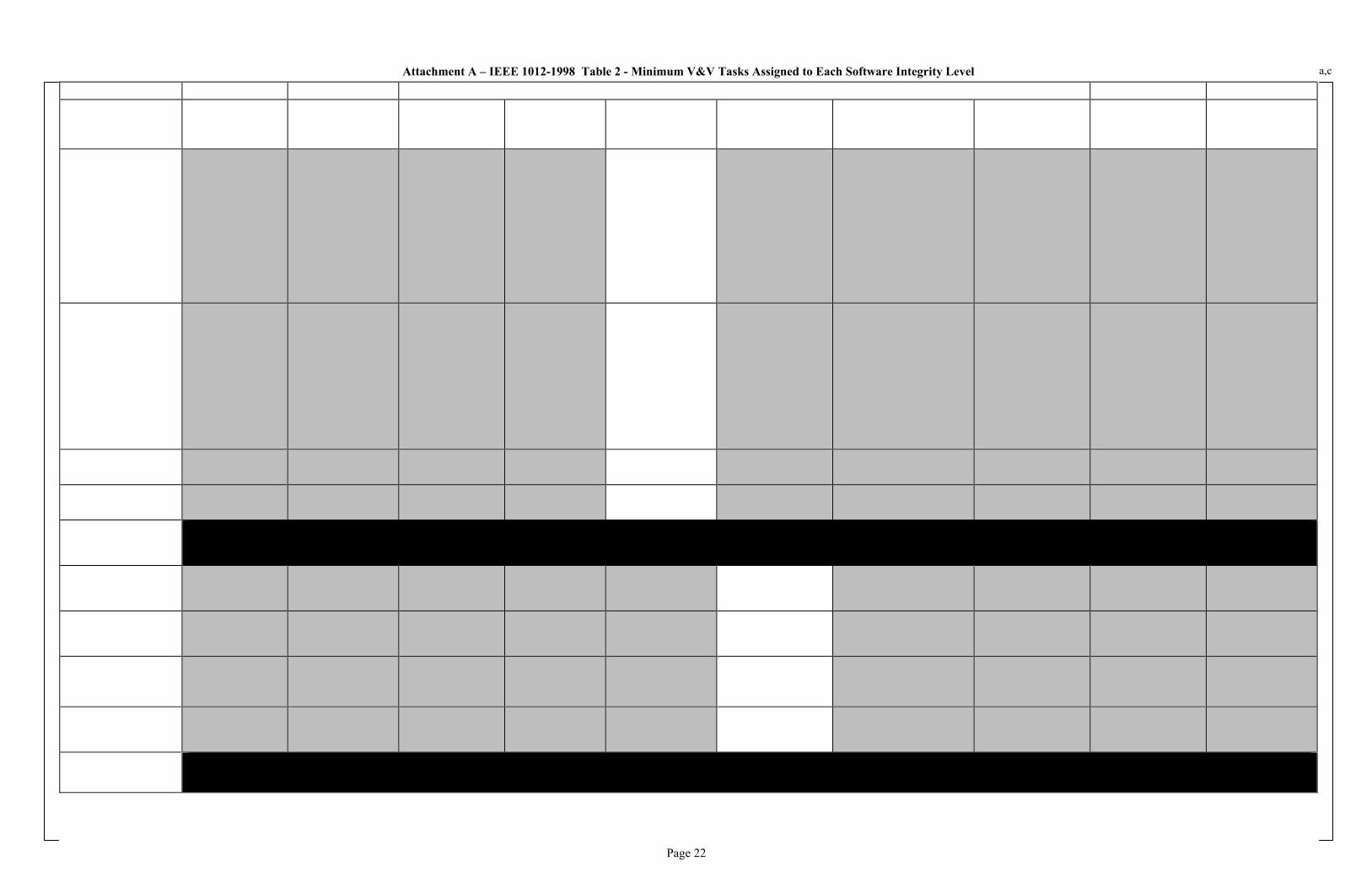
Page 22
Attachment A – IEEE 1012-1998 Table 2 - Minimum V&V Tasks Assigned to Each Software Integrity Level
a,c

Page 23
Attachment A – IEEE 1012-1998 Table 2 - Minimum V&V Tasks Assigned to Each Software Integrity Level
a,c

Page 24
Attachment B – Software Program Manual for Common Q Systems (WCAP-16096) Compliance to RG 1.152, Rev. 3
a,c

Page 25
Attachment C – Table II. Information Requirements
SPM Section Number Description of Requirement Output Document Output Phase
1.4.2 Training Record For SPM Training Record N/A
3.1.2 Defining Acceptable Risks Project Plan Concept
3.3.2 A detailed schedule Project Plan Concept
3.3.2 Resource Plan Project Plan Concept
3.3.5.10 Software User Documentation Technical Manual Test Phase
3.3.5.11 Results of Software Safety Requirements Analysis
IV&V Report Requirements Phase
3.3.5.12 Results of Software Safety Design Analysis IV&V Report Design Phase
3.3.5.13 Results of Software Safety Code Analysis IV&V Report Implementation Phase
3.3.5.14 Results of Software Safety Test Analysis IV&V Report Test Phase
3.3.5.15 Results of Software Safety Change Analysis IV&V Report Maintenance Phase
3.3.6 Software Hazards Software Hazards Analysis Report
Requirements Phase
3.3.6 Results of IV&V Analyses IV&V Report All Phases
3.3.6 Information on suspected or confirmed safety problems
IV&V Report Test Phase
3.3.6 Results of audits performed on software safety program tasks
Audit Report Test Phase
3.3.6 Results of safety tests conducted on the system Test Reports Test Phase
3.3.6 Training Records Training Record N/A
3.3.6 Software Safety Certification – Code Certificate IV&V Report Test Phase
3.3.6 Tracking system to ensure hazards and their statuses are tracked throughout software life cycle
Requirements Traceability Matrix
All Phases
3.3.10 Project Manager approves the use of any tool – approval implicit by listing tool in Plan
Project Plan Concept Phase
3.4.1 Software Hazards Analysis Software Hazards Analysis Report
Requirements Phase
3.4.2 Software Safety Requirements Analysis IV&V Report Requirements Phase
3.4.3 Software Safety Design Analysis IV&V Report Design Phase
3.4.4 Software Safety Code Analysis IV&V Report Implementation Phase
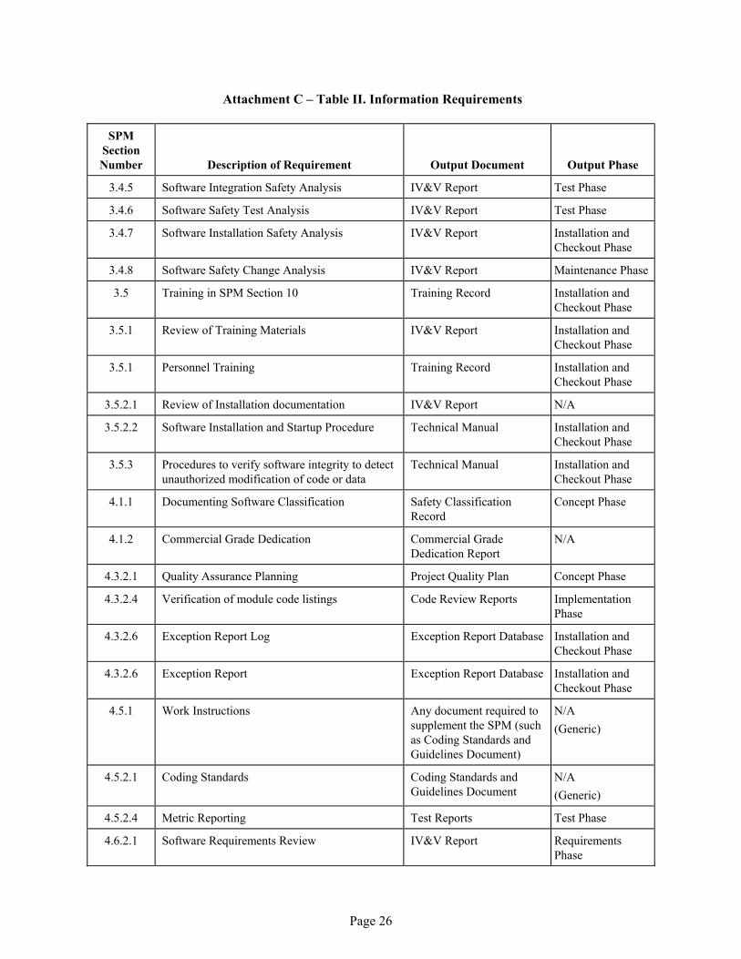
Page 26
Attachment C – Table II. Information Requirements
SPM Section Number Description of Requirement Output Document Output Phase
3.4.5 Software Integration Safety Analysis IV&V Report Test Phase
3.4.6 Software Safety Test Analysis IV&V Report Test Phase
3.4.7 Software Installation Safety Analysis IV&V Report Installation and Checkout Phase
3.4.8 Software Safety Change Analysis IV&V Report Maintenance Phase
3.5 Training in SPM Section 10 Training Record Installation and Checkout Phase
3.5.1 Review of Training Materials IV&V Report Installation and Checkout Phase
3.5.1 Personnel Training Training Record Installation and Checkout Phase
3.5.2.1 Review of Installation documentation IV&V Report N/A
3.5.2.2 Software Installation and Startup Procedure Technical Manual Installation and Checkout Phase
3.5.3 Procedures to verify software integrity to detect unauthorized modification of code or data
Technical Manual Installation and Checkout Phase
4.1.1 Documenting Software Classification Safety Classification Record
Concept Phase
4.1.2 Commercial Grade Dedication Commercial Grade Dedication Report
N/A
4.3.2.1 Quality Assurance Planning Project Quality Plan Concept Phase
4.3.2.4 Verification of module code listings Code Review Reports Implementation Phase
4.3.2.6 Exception Report Log Exception Report Database Installation and Checkout Phase
4.3.2.6 Exception Report Exception Report Database Installation and Checkout Phase
4.5.1 Work Instructions Any document required to supplement the SPM (such as Coding Standards and Guidelines Document)
N/A
(Generic)
4.5.2.1 Coding Standards Coding Standards and Guidelines Document
N/A
(Generic)
4.5.2.4 Metric Reporting Test Reports Test Phase
4.6.2.1 Software Requirements Review IV&V Report Requirements Phase

Page 27
Attachment C – Table II. Information Requirements
SPM Section Number Description of Requirement Output Document Output Phase
4.6.2.2.1 Architecture Design Review IV&V Report Design Phase
4.6.2.2.2 Critical Design Review IV&V Report Design Phase
4.6.2.3 Code Certification Code Review Reports Implementation Phase
4.6.2.4 SVVP Review SPM Concept Phase
4.6.2.5 Functional Review IV&V Report Test Phase
4.6.2.6 Physical Review Certificate of Conformance and IV&V Report
Installation and Checkout Phase
4.6.2.7 In-process Audits Audit Report All Phases
4.6.2.8 Managerial Reviews Audit Report All Phases
4.6.2.9 Software Configuration Management Plan Review
IV&V Report Concept Phase
4.6.2.10 Post Mortem Review CAPs (LN Database) Installation and Checkout Phase
5.1.4 Project-Specific IV&V Plan Activities Project Plan Concept Phase
5.4.5.2 IV&V Checklists IV&V Report All Phases
5.4.5.2 Review Changes to COTS software Commercial Grade Dedication Report
Concept Phase
5.4.5.3 Requirements Traceability Analysis RTM or Requirements Management Database
Requirements thru Test Phase
5.4.5.4 Database reviews (see also 5.5.5.2 #5) Implementation Phase Checklist in IV&V Report
Implementation Phase
5.5.1 Baseline Change Assessment Regression Analysis All Phases
5.5.3.2 Software Safety Analyses IV&V Report Requirements Phase
5.5.4.2 Software Safety Design Analyses IV&V Report Design Phase
5.5.5.2 Software Safety Code Analyses IV&V Report Implementation Phase
5.5.6 Software Safety Test Analysis Test Phase Checklist in IV&V Report
Test Phase
5.5.6.3 Code Certificate IV&V Report Test Phase
5.5.7.1 Installation Procedures, System Generation Procedures, User Documentation
Technical Manual Installation and Checkout Phase

Page 28
Attachment C – Table II. Information Requirements
SPM Section Number Description of Requirement Output Document Output Phase
5.5.7.2 Training Material Training Program Per Customer Requirements
Installation and Checkout Phase
5.5.8 Regression Analysis IV&V Report or separately prepared document
Operations and Maintenance Phase
5.6.1 Discrepancy Reports Exception Record Database; Status defined in IV&V Report
All Phases
6.2.2.1 Define ENM software items which are to be controlled via SCM
Project Quality Plan Requirements Phase
6.2.2.3 Define software items which are to be controlled via SCM
Project Plan Implementation Phase
6.3.2 Master list of software under configuration control for a project
Software Release Record Implementation Phase
6.3.2 Software Change Request Database Implementation Phase, Test Phase, and Maintenance Phase
6.3.2 Software Change Request Log Database Implementation Phase, Test Phase, and Maintenance Phase
6.3.3 Configuration Status Accounting Configuration Management Release Report
All Phases
8.3.2.1 Feasibility Analysis Project Quality Plan Concept Phase
8.3.2.2 Detailed Analysis SysRS, SRS, Test Plan, PQP
Requirements Phase
8.5.2.4 Risk Analysis Project Quality Plan Implementation Phase
10.2 Justification for not performing complete system retesting
Regression Analysis in Exception Report or SCR
Test Phase
10.2 Exception Reports Database All Phases

Page 29
Attachment D – Exhibit 2-1 Design/IV&V Team Organization
* The IV&V Organization is comprised of multiple IV&V groups.

Page 30
Attachment E1 – AC160 Application Code Review Checklist
a,c

Page 31
Attachment E2 – Software Module Review Checklist
a,c
Page 32
Attachment E3 – FPD Software Module Review Checklist
a,c
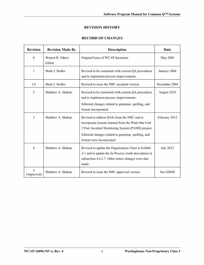
Software Program Manual for Common Q™ Systems
WCAP-16096-NP-A, Rev. 4 i Westinghouse Non-Proprietary Class 3
REVISION HISTORY
RECORD OF CHANGES
Revision Revision Made By Description Date
0 Warren R. Odess-
Gillett
Original Issue of WCAP document May 2003
1 Mark J. Stofko Revised to be consistent with current QA procedures
and to implement process improvements.
January 2004
1A Mark J. Stofko Revised to issue the NRC accepted version. December 2004
2 Matthew A. Shakun Revised to be consistent with current QA procedures
and to implement process improvements.
Editorial changes related to grammar, spelling, and
format incorporated.
August 2010
3 Matthew A. Shakun Revised to address RAIs from the NRC and to
incorporate lessons learned from the Watts Bar Unit
2 Post Accident Monitoring System (PAMS) project.
Editorial changes related to grammar, spelling, and
format were incorporated.
February 2012
4 Matthew A. Shakun Revised to update the Organization Chart in Exhibit
2-1 and to update the In-Process Audit description in
subsection 4.6.2.7. Other minor changes were also
made.
July 2012
4 (Approved)
Matthew A. Shakun Revised to issue the NRC approved version. See EDMS

Software Program Manual for Common Q™ Systems
WCAP-16096-NP-A, Rev. 4 ii Westinghouse Non-Proprietary Class 3
DETAILED RECORD OF CHANGES
Revision 4 (NRC Approved) February 2013
Description:
Revision 4 was modified to incorporate the following changes:
Change the last sentence in the PQP definition from “A project plan and PQP can be combined in one
document.” to “When the SPM refers to a PQP, it includes the Project Quality Plan and Project Plan
defined in the Westinghouse Quality Procedures.” So when the SPM states that something will be added
to the PQP, (e.g., “Any alternatives to the SPM processes or additional project specific information for the
SQAP, SVVP, SCMP or SOMP shall be documented and justified in the PQP.”) that the information
could be added to either the PQP or the project plan.
IEEE Std. 1074-1997 was changed to IEEE Std. 1074-1995 to be consistent with the latest endorsed
regulatory guide
Section 1.4 was updated to add a pointer to Exhibit 5-1, which clarifies that there is a distinction between
activities performed for Protection and Important-to-Safety class software in regards to IEEE Std. 7-4.3.2.
The description of the Software Hazards Analysis in subsection 3.4.1 was updated to clarify that for
systems that use both Protection and Important-to-Safety class software, the analysis must consider
potential hazards in Important-to-Safety software and the impact on Protection class software.
The description of Westinghouse’s organization in subsection 4.3.1 was updated to be consistent with the
Westinghouse organization depicted in Exhibit 2-1.
Exhibit 4-1 was updated to change “Inter-System Communication Software” to “Intra-Divisional
Communication Software (AF100).”
Exhibit 5-1 was revised to replace note ** from “REQUIREMENTS VERIFICATION,” “DESIGN
VERIFICATION,” and “IMPLEMENTATION VERIFICATION” with note ***, which says: “Same
IV&V activities as Protection Class software except for Software Hazards Analysis described in
subsection 3.4.1.”
Exhibit 5-1 was also revised to remove Note ** from the Module Coding activity.

Software Program Manual for Common Q™ Systems
WCAP-16096-NP-A, Rev. 4 iii Westinghouse Non-Proprietary Class 3
DETAILED RECORD OF CHANGES (cont.)
Exhibit 5-8 was updated to add the following notes for clarification: 1. “Component Testing is equated to Module Testing, and documented Module Testing is only
required for Protection class software.” This note was added to all component testing activities. 2. “Only applicable for Protection class software.” This note was added to the Hazards Analysis
activity.
The following typographical errors were fixed:
- “Common Q” was changed to “Common Q™” throughout the document. Note: This change is
not marked by a change bar.
- Section 10.3: “to” was deleted
- Subsection 12.2.4: “Development Environment” was changed to “Implementation Phase”

Software Program Manual for Common Q™ Systems
WCAP-16096-NP-A, Rev. 4 iv Westinghouse Non-Proprietary Class 3
TABLE OF CONTENTS
Section Title Page
REVISION HISTORY .............................................................................................. i
DETAILED RECORD OF CHANGES ..................................................................... ii
TABLE OF CONTENTS ........................................................................................... iv
LIST OF TABLES ..................................................................................................... xiv
LIST OF FIGURES ................................................................................................... xiv
ACRONYMS AND TRADEMARKS ....................................................................... xv
GLOSSARY OF TERMS .......................................................................................... xviii
REFERENCES .......................................................................................................... xxii
DOCUMENTATION REQUIREMENTS ................................................................. xxv
SECTION 1 INTRODUCTION .......................................................................................................1-1
1.1 PURPOSE ....................................................................................................................1-1
1.2 SCOPE .........................................................................................................................1-2
1.2.1 Software Classification and Categorization .................................................................1-2
1.2.2 Software Exclusions ....................................................................................................1-4
1.3 OVERVIEW ................................................................................................................1-4
1.4 GENERAL REQUIREMENTS ...................................................................................1-5
1.4.1 Software Life Cycle .....................................................................................................1-6
1.4.2 Indoctrination and Training .........................................................................................1-6
SECTION 2 ORGANIZATION .......................................................................................................2-1
SECTION 3 SOFTWARE SAFETY PLAN ....................................................................................3-1
3.1 INTRODUCTION .......................................................................................................3-1
3.1.1 PURPOSE ....................................................................................................................3-1
3.1.2 SCOPE .........................................................................................................................3-1
3.2 DEFINITIONS, ACRONYMS, ABBREVIATIONS, AND REFERENCES .............3-1
3.3 SOFTWARE SAFETY MANAGEMENT ..................................................................3-1
3.3.1 Organization and Responsibilities ...............................................................................3-1
3.3.2 Resources .....................................................................................................................3-2
3.3.3 Staff Qualifications And Training ...............................................................................3-3
3.3.4 Software Life Cycle .....................................................................................................3-4
3.3.5 Documentation Requirements ......................................................................................3-5
3.3.5.1 Software Project Management .....................................................................................3-5
3.3.5.2 Software Configuration Management ..........................................................................3-5
3.3.5.3 Software Quality Assurance ........................................................................................3-5

Software Program Manual for Common Q™ Systems
WCAP-16096-NP-A, Rev. 4 v Westinghouse Non-Proprietary Class 3
TABLE OF CONTENTS (cont.)
3.3.5.4 Software Safety Requirements .....................................................................................3-5
3.3.5.5 Software Design Description .......................................................................................3-5
3.3.5.6 Software Development Methodology, Standards, Practices, Metrics and Conventions
.....................................................................................................................................3-5
3.3.5.7 Test Documentation .....................................................................................................3-6
3.3.5.8 Software Verification and Validation ..........................................................................3-6
3.3.5.9 Reporting Safety Verification and Validation .............................................................3-6
3.3.5.10 Software User Documentation .....................................................................................3-6
3.3.5.11 Results of Software Safety Requirements Analysis .....................................................3-7
3.3.5.12 Results of Software Safety Design Analysis................................................................3-7
3.3.5.13 Results of Software Safety Code Analysis ..................................................................3-7
3.3.5.14 Results of Software Safety Test Analysis ....................................................................3-7
3.3.5.15 Results of Software Safety Change Analysis ...............................................................3-7
3.3.6 Software Safety Program Records ...............................................................................3-7
3.3.7 Software Configuration Management Activities .........................................................3-8
3.3.8 Software Quality Assurance Activities ........................................................................3-8
3.3.9 Software Verification and Validation Activities ..........................................................3-8
3.3.10 Tool Support and Approval .........................................................................................3-8
3.3.11 Previously Developed or Purchased Software .............................................................3-9
3.3.12 Subcontract Management.............................................................................................3-9
3.3.13 Process Certification ....................................................................................................3-9
3.4 SOFTWARE SAFETY ANALYSES ..........................................................................3-9
3.4.1 Software Safety Analyses Preparation .........................................................................3-9
3.4.2 Software Safety Requirements Analysis ......................................................................3-10
3.4.3 Software Safety Design Analysis .................................................................................3-11
3.4.4 Software Safety Code Analysis ...................................................................................3-11
3.4.5 Software Integration Safety Analysis ..........................................................................3-11
3.4.6 Software Safety Test Analysis .....................................................................................3-11
3.4.7 Software Installation Safety Analysis ..........................................................................3-11
3.4.8 Software Safety Change Analysis ................................................................................3-11
3.5 POST DEVELOPMENT .............................................................................................3-12
3.5.1 Training ........................................................................................................................3-12
3.5.2 Deployment ..................................................................................................................3-12
3.5.2.1 Installation ...................................................................................................................3-12
3.5.2.2 Startup and Transition ..................................................................................................3-12
3.5.2.3 Operations Support ......................................................................................................3-13
3.5.3 Monitoring ...................................................................................................................3-13
3.5.4 Maintenance .................................................................................................................3-13
3.5.5 Retirement and Notification .........................................................................................3-13

Software Program Manual for Common Q™ Systems
WCAP-16096-NP-A, Rev. 4 vi Westinghouse Non-Proprietary Class 3
TABLE OF CONTENTS (cont.)
Section 4 software Quality Assurance plan .................................................................................4-1
4.1 INTRODUCTION .......................................................................................................4-1
4.1.1 Purpose ........................................................................................................................4-1
4.1.2 Scope ............................................................................................................................4-1
4.1.3 Software Development Process ...................................................................................4-3
4.2 REFERENCES ............................................................................................................4-3
4.3 MANAGEMENT .........................................................................................................4-4
4.3.1 Organization .................................................................................................................4-4
4.3.2 Tasks and Responsibilities ...........................................................................................4-5
4.3.2.1 Initiation (Concept) Phase ...........................................................................................4-5
4.3.2.2 Software Requirements Phase ......................................................................................4-6
4.3.2.3 Software Design Phase ................................................................................................4-7
4.3.2.4 Software Implementation Phase ..................................................................................4-7
4.3.2.5 Testing Phase ...............................................................................................................4-8
4.3.2.6 Site Installation and Checkout Phase ...........................................................................4-9
4.3.2.7 Operations and Maintenance Phase .............................................................................4-9
4.4 DOCUMENTATION ..................................................................................................4-10
4.4.1 Purpose ........................................................................................................................4-10
4.5 STANDARDS, PRACTICES, CONVENTIONS, AND METRICS ...........................4-10
4.5.1 Purpose ........................................................................................................................4-10
4.5.2 Content .........................................................................................................................4-10
4.5.2.1 Coding Standards .........................................................................................................4-10
4.5.2.2 Software Testing Standards .........................................................................................4-12
4.5.2.3 Documentation Standards ............................................................................................4-12
4.5.2.4 Metrics .........................................................................................................................4-12
4.6 REVIEWS ....................................................................................................................4-13
4.6.1 Purpose ........................................................................................................................4-13
4.6.2 Minimum Requirements ..............................................................................................4-14
4.6.2.1 Software Requirements Review (SRR) .......................................................................4-14
4.6.2.2 Software Design Review .............................................................................................4-15
4.6.2.3 Code Verification .........................................................................................................4-16
4.6.2.4 Software Verification and Validation Plan Review .....................................................4-17
4.6.2.5 Functional Review .......................................................................................................4-17
4.6.2.6 Physical Review ...........................................................................................................4-17
4.6.2.7 In-Process Audits .........................................................................................................4-17
4.6.2.8 Managerial Reviews ....................................................................................................4-18
4.6.2.9 Software Configuration Management Plan Review .....................................................4-18
4.6.2.10 Post Mortem Review ...................................................................................................4-18
4.7 TEST ............................................................................................................................4-18

Software Program Manual for Common Q™ Systems
WCAP-16096-NP-A, Rev. 4 vii Westinghouse Non-Proprietary Class 3
TABLE OF CONTENTS (cont.)
4.8 PROBLEM REPORTING AND CORRECTIVE ACTION .......................................4-19
4.8.1 Purpose and Scope .......................................................................................................4-19
4.9 TOOLS, TECHNIQUES AND METHODOLOGIES .................................................4-19
4.10 CODE CONTROL .......................................................................................................4-20
4.11 MEDIA CONTROL ....................................................................................................4-20
4.11.1 Media Identification .....................................................................................................4-20
4.11.2 Archival Requirements ................................................................................................4-20
4.12 SUPPLIER CONTROL ...............................................................................................4-21
4.12.1 Existing Software .........................................................................................................4-21
4.12.2 Sub-Contracted Software/Services ..............................................................................4-22
4.13 RECORDS COLLECTION, MAINTENANCE AND RETENTION .........................4-22
4.14 TRAINING ..................................................................................................................4-23
4.15 RISK MANAGEMENT ..............................................................................................4-23
SECTION 5 SOFTWARE VERIFICATION AND VALIDATION PLAN ....................................5-1
5.1 PURPOSE ....................................................................................................................5-1
5.1.1 Categorization of Software Items and Review Scope ..................................................5-1
5.1.2 IV&V Program Implementation ..................................................................................5-1
5.1.3 Prominence of IV&V Documentation .........................................................................5-2
5.1.4 Overall Common Q™ and System-Specific IV&V Plans ...........................................5-2
5.2 REFERENCED DOCUMENTS ..................................................................................5-3
5.3 DEFINITIONS .............................................................................................................5-3
5.4 VERIFICATION AND VALIDATION OVERVIEW ................................................5-3
5.4.1 Organization .................................................................................................................5-3
5.4.2 Master Schedule ...........................................................................................................5-4
5.4.3 Resources Summary ....................................................................................................5-4
5.4.3.1 Design Team ................................................................................................................5-4
5.4.3.2 Independent Verification and Validation Team ...........................................................5-5
5.4.4 Responsibilities ............................................................................................................5-6
5.4.4.1 Independent Verification and Validation Team Responsibilities ................................5-6
5.4.5 Tools, Techniques, and Methodologies .......................................................................5-6
5.4.5.1 Automated Tools ..........................................................................................................5-6
5.4.5.2 IV&V Core Activities ..................................................................................................5-6
5.4.5.3 Requirements Traceability Analysis ............................................................................5-8
5.4.5.4 Database Review/Testing ............................................................................................5-9
5.5 LIFE CYCLE VERIFICATION AND VALIDATION ...............................................5-10
5.5.1 Management of IV&V .................................................................................................5-10
5.5.2 Concept (Initiation) Phase IV&V ................................................................................5-11

Software Program Manual for Common Q™ Systems
WCAP-16096-NP-A, Rev. 4 viii Westinghouse Non-Proprietary Class 3
TABLE OF CONTENTS (cont.)
5.5.2.1 IV&V Inputs ................................................................................................................5-11
5.5.2.2 IV&V Tasks .................................................................................................................5-11
5.5.2.3 IV&V Outputs ..............................................................................................................5-12
5.5.3 Requirements Phase IV&V ..........................................................................................5-12
5.5.3.1 IV&V Inputs ................................................................................................................5-13
5.5.3.2 IV&V Tasks .................................................................................................................5-13
5.5.3.3 IV&V Outputs ..............................................................................................................5-16
5.5.4 Design Phase IV&V .....................................................................................................5-17
5.5.4.1 IV&V Inputs ................................................................................................................5-17
5.5.4.2 IV&V Tasks .................................................................................................................5-17
5.5.4.3 IV&V Outputs ..............................................................................................................5-18
5.5.5 Implementation Phase IV&V .......................................................................................5-19
5.5.5.1 IV&V Inputs ................................................................................................................5-19
5.5.5.2 IV&V Tasks .................................................................................................................5-19
5.5.5.3 IV&V Outputs ..............................................................................................................5-21
5.5.6 Test Phase IV&V .........................................................................................................5-22
5.5.6.1 IV&V Inputs ................................................................................................................5-23
5.5.6.2 IV&V Tasks .................................................................................................................5-24
5.5.6.3 IV&V Outputs ..............................................................................................................5-25
5.5.7 Installation and Checkout Phase IV&V .......................................................................5-25
5.5.7.1 IV&V Inputs ................................................................................................................5-25
5.5.7.2 IV&V Tasks .................................................................................................................5-25
5.5.7.3 IV&V Outputs ..............................................................................................................5-26
5.5.8 Operation and Maintenance Phase IV&V ....................................................................5-27
5.6 SOFTWARE VERIFICATION AND VALIDATION REPORTING ........................5-27
5.6.1 Required Reports .........................................................................................................5-27
5.6.2 Optional Reports ..........................................................................................................5-28
5.7 VERIFICATION AND VALIDATION ADMINISTRATIVE PROCEDURES ........5-28
5.7.1 Anomaly Reporting and Resolution .............................................................................5-28
5.7.2 Task Iteration Policy ....................................................................................................5-29
5.7.3 Deviation Policy ..........................................................................................................5-29
5.7.4 Control Procedures ......................................................................................................5-29
5.7.5 Standards, Practices, and Conventions ........................................................................5-29
5.8 IV&V TEST DOCUMENTATION REQUIREMENTS .............................................5-29
5.8.1 Test Plan ......................................................................................................................5-29
5.8.2 Test Procedure .............................................................................................................5-29
5.8.2.1 Test-Design Specification ............................................................................................5-30
5.8.2.2 Test-Case Specification ...............................................................................................5-30
5.8.2.3 Test-Procedure Specification .......................................................................................5-30

Software Program Manual for Common Q™ Systems
WCAP-16096-NP-A, Rev. 4 ix Westinghouse Non-Proprietary Class 3
TABLE OF CONTENTS (cont.)
5.8.3 Test Report ...................................................................................................................5-30
5.9 SOFTWARE INTEGRITY LEVEL SCHEME ...........................................................5-30
SECTION 6 SOFTWARE CONFIGURATION MANAGEMENT PLAN .....................................6-1
6.1 INTRODUCTION .......................................................................................................6-1
6.1.1 Purpose ........................................................................................................................6-1
6.1.2 Scope ............................................................................................................................6-2
6.1.3 Definitions ...................................................................................................................6-3
6.1.4 References ....................................................................................................................6-3
6.2 MANAGEMENT .........................................................................................................6-3
6.2.1 Organization .................................................................................................................6-3
6.2.2 SCM Responsibilities ..................................................................................................6-3
6.2.2.1 Requirement Phase ......................................................................................................6-3
6.2.2.2 Design Phase ................................................................................................................6-4
6.2.2.3 Implementation Phase ..................................................................................................6-4
6.2.2.4 Test Phase ....................................................................................................................6-4
6.2.2.5 Installation and Checkout Phase ..................................................................................6-5
6.2.2.6 Operations and Maintenance Phase .............................................................................6-5
6.2.2.7 Retirement Phase .........................................................................................................6-6
6.2.2.8 Configuration Identification Management ...................................................................6-6
6.2.2.9 Configuration Control Management ............................................................................6-6
6.2.2.10 Configuration Status Accounting Management ...........................................................6-6
6.2.2.11 Configuration Reviews and Audits ..............................................................................6-6
6.2.2.12 Configuration Control Board .......................................................................................6-6
6.2.3 Applicable Policies, Directives, and Procedures .........................................................6-7
6.2.4 Management of the SCM Process ................................................................................6-7
6.3 SOFTWARE CONFIGURATION MANAGEMENT ACTIVITIES .........................6-7
6.3.1 Configuration Identification.........................................................................................6-7
6.3.1.1 Acquiring Configuration Items ....................................................................................6-9
6.3.2 Configuration Change Control .....................................................................................6-9
6.3.3 Configuration Status Accounting .................................................................................6-11
6.3.4 Configuration Audits and Reviews ..............................................................................6-12
6.3.5 Interface Control ..........................................................................................................6-12
6.3.6 Subcontractor/Vendor Control .....................................................................................6-13
6.3.6.1 Subcontractor Software ................................................................................................6-13
6.3.6.2 Vendor Software ..........................................................................................................6-13
6.3.7 Release Management and Delivery .............................................................................6-14
6.4 SCM SCHEDULES .....................................................................................................6-14

Software Program Manual for Common Q™ Systems
WCAP-16096-NP-A, Rev. 4 x Westinghouse Non-Proprietary Class 3
TABLE OF CONTENTS (cont.)
6.5 SCM RESOURCES .....................................................................................................6-14
6.6 SCM PLAN MAINTENANCE ...................................................................................6-15
SECTION 7 SOFTWARE TEST PLAN ..........................................................................................7-1
7.1 INTRODUCTION .......................................................................................................7-1
7.1.1 OVERVIEW ................................................................................................................7-1
7.1.2 SCOPE .........................................................................................................................7-1
7.1.3 OBJECTIVE ................................................................................................................7-1
7.2 TESTING PROCESS OVERVIEW ............................................................................7-1
7.2.1 Organization .................................................................................................................7-1
7.2.2 Staffing and Training ...................................................................................................7-2
7.2.2.1 Duties ...........................................................................................................................7-2
7.2.2.2 Qualifications ...............................................................................................................7-2
7.2.3 Responsibilities ............................................................................................................7-2
7.2.4 Schedule .......................................................................................................................7-3
7.2.5 Testing Environment ....................................................................................................7-3
7.2.5.1 Testing Hardware .........................................................................................................7-4
7.2.5.2 Security ........................................................................................................................7-4
7.2.6 Test Tools ....................................................................................................................7-5
7.2.7 Features and Functions to be Tested ............................................................................7-5
7.2.8 Risks and Contingencies ..............................................................................................7-5
7.2.9 Standards, Practices, and Conventions ........................................................................7-5
7.3 TESTING PROCESS ACTIVITIES AND TASKS ....................................................7-5
7.3.1 Testing Methodology ...................................................................................................7-6
7.3.1.1 Module Test .................................................................................................................7-6
7.3.1.2 Unit Test ......................................................................................................................7-7
7.3.1.3 Integration Test ............................................................................................................7-7
7.3.1.4 Factory Acceptance Test (FAT) ...................................................................................7-8
7.3.1.5 Site Acceptance Test (SAT) .........................................................................................7-9
7.3.2 Pass/Fail Criteria and Regression Testing ...................................................................7-9
7.3.2.1 Pass/Fail Criteria ..........................................................................................................7-9
7.3.2.2 Regression Testing .......................................................................................................7-9
SECTION 8 SOFTWARE INSTALLATION PLAN ......................................................................8-1
8.1 PURPOSE ....................................................................................................................8-1
8.2 OVERVIEW ................................................................................................................8-1
8.3 AC160 SOFTWARE INSTALLATION .....................................................................8-1
8.3.1 AC160 Base Software Installation ...............................................................................8-1
8.3.1.1 Loading the AC160 Communication System Software (CS) ......................................8-1

Software Program Manual for Common Q™ Systems
WCAP-16096-NP-A, Rev. 4 xi Westinghouse Non-Proprietary Class 3
TABLE OF CONTENTS (cont.)
8.3.1.2 Loading the AC160 Base Software (PS) .....................................................................8-2
8.3.1.3 Loading the AC160 Software Library Options (PS) ....................................................8-2
8.3.2 AC160 Application Software Installation ....................................................................8-2
8.3.2.1 Installation of AC160 Application Software ...............................................................8-2
8.4 FLAT PANEL DISPLAY SYSTEM (FPDS) SOFTWARE INSTALLATION .........8-2
8.4.1 FPDS Operating System Software Installation ............................................................8-2
8.4.2 Loading the FPDS Application Software ....................................................................8-3
SECTION 9 SOFTWARE MAINTENANCE PLAN ......................................................................9-1
9.1 INTRODUCTION .......................................................................................................9-1
9.2 PROBLEM/MODIFICATION IDENTIFICATION, CLASSIFICATION AND
PRIORITIZATION ......................................................................................................9-1
9.2.1 Input .............................................................................................................................9-1
9.2.2 Process .........................................................................................................................9-1
9.2.3 Control .........................................................................................................................9-2
9.2.4 Output ..........................................................................................................................9-2
9.3 ANALYSIS ..................................................................................................................9-2
9.3.1 Analysis Input ..............................................................................................................9-2
9.3.2 Analysis Process ..........................................................................................................9-2
9.3.2.1 Feasibility Analysis ......................................................................................................9-2
9.3.2.2 Detailed Analysis .........................................................................................................9-3
9.3.3 Analysis Control ..........................................................................................................9-3
9.3.4 Analysis Output ...........................................................................................................9-4
9.4 DESIGN .......................................................................................................................9-4
9.4.1 Design Input .................................................................................................................9-4
9.4.2 Design Process .............................................................................................................9-4
9.4.3 Design Control .............................................................................................................9-5
9.4.4 Design Output ..............................................................................................................9-5
9.5 IMPLEMENTATION ..................................................................................................9-5
9.5.1 Implementation Input ...................................................................................................9-5
9.5.2 Implementation Process ...............................................................................................9-5
9.5.2.1 Coding and Module Testing.........................................................................................9-5
9.5.2.2 Integration ....................................................................................................................9-5
9.5.2.3 Documentation .............................................................................................................9-6
9.5.2.4 Risk Analysis and Test-Readiness Review ..................................................................9-6
9.5.3 Implementation Control ...............................................................................................9-6
9.5.4 Implementation Output ................................................................................................9-6
9.6 TEST ............................................................................................................................9-6
9.6.1 Test Input .....................................................................................................................9-6

Software Program Manual for Common Q™ Systems
WCAP-16096-NP-A, Rev. 4 xii Westinghouse Non-Proprietary Class 3
TABLE OF CONTENTS (cont.)
9.6.2 Test Process .................................................................................................................9-7
9.6.3 Test Control .................................................................................................................9-7
9.6.4 Test Output ..................................................................................................................9-7
9.7 DELIVERY .................................................................................................................9-7
9.7.1 Input .............................................................................................................................9-7
9.7.2 Process .........................................................................................................................9-7
9.7.3 Control .........................................................................................................................9-8
9.7.4 Output ..........................................................................................................................9-8
SECTION 10 DOCUMENTATION ..................................................................................................10-1
10.1 GENERAL REQUIREMENTS ...................................................................................10-1
10.2 SYSTEM REQUIREMENTS DOCUMENTATION ..................................................10-1
10.2.1 System Requirements Specification (SysRS) ..............................................................10-1
10.2.2 Software Requirements Specification (SRS) ...............................................................10-2
10.3 SOFTWARE DESIGN DESCRIPTION (SDD) ..........................................................10-2
10.4 SOURCE CODE DOCUMENTATION ......................................................................10-3
10.5 SOFTWARE VERIFICATION AND VALIDATION DOCUMENTATION ............10-3
10.5.1 Software Verification and Validation Plan ..................................................................10-3
10.5.2 Software Verification and Validation Report ..............................................................10-4
10.6 USER DOCUMENTATION .......................................................................................10-4
10.7 SOFTWARE CONFIGURATION MANAGEMENT DOCUMENTATION ............10-5
10.8 TEST DOCUMENTATION ........................................................................................10-5
10.8.1 Test Plans .....................................................................................................................10-5
10.8.2 Test Procedures ............................................................................................................10-5
10.9 SOFTWARE/DATABASE RELEASE RECORDS ....................................................10-5
10.10 COMPUTER CODE CERTIFICATE .........................................................................10-5
SECTION 11 PROBLEM REPORTING AND CORRECTIVE ACTION .......................................11-1
11.1 INTRODUCTION .......................................................................................................11-1
11.2 ERROR REPORTING BEFORE SOFTWARE APPROVAL FOR USE ...................11-1
11.3 ERROR REPORTING AFTER SOFTWARE APPROVAL FOR USE .....................11-2
11.4 CORRECTIVE ACTION ............................................................................................11-2
SECTION 12 SECURE DEVELOPMENT AND OPERATIONAL ENVIRONMENT PLAN .......12-1
12.1 INTRODUCTION .......................................................................................................12-1
12.1.1 Overview ......................................................................................................................12-1
12.2 LIFE CYCLE PHASE ACTIVITIES ..........................................................................12-1
12.2.1 Concept Phase ..............................................................................................................12-1
12.2.1.1 System Security Capabilities .......................................................................................12-1

Software Program Manual for Common Q™ Systems
WCAP-16096-NP-A, Rev. 4 xiii Westinghouse Non-Proprietary Class 3
TABLE OF CONTENTS (cont.)
12.2.1.2 Identification of Life cycle Vulnerabilities ..................................................................12-3
12.2.1.3 Outputs from the Concept Phase ..................................................................................12-6
12.2.2 Requirements Phase .....................................................................................................12-6
12.2.2.1 System Features – Security Functional Performance Requirements ...........................12-6
12.2.2.2 Development System Requirements ............................................................................12-8
12.2.2.3 Requirements Phase Outputs .......................................................................................12-9
12.2.3 Detailed Design Phase .................................................................................................12-9
12.2.3.1 System Features ...........................................................................................................12-9
12.2.3.2 Development Activities for the Design Phase .............................................................12-9
12.2.3.3 Design Phase Outputs ..................................................................................................12-10
12.2.4 Implementation Phase ..................................................................................................12-10
12.2.4.1 Systems Features ..........................................................................................................12-10
12.2.4.2 Development Activities for the Implementation Phase ...............................................12-10
12.2.4.3 Implementation Phase Outputs ....................................................................................12-11
12.2.5 TESTING PHASE .......................................................................................................12-11
12.2.5.1 System Features ...........................................................................................................12-11
12.2.5.2 Development Activities for the Testing Phase .............................................................12-11
12.2.5.3 Testing Phase Outputs .................................................................................................12-12
SECTION 13 EXHIBITS ...................................................................................................................13-1
Software Program Manual for Common Q™ Systems
WCAP-16096-NP-A, Rev. 4 xiv Westinghouse Non-Proprietary Class 3
TABLE OF CONTENTS (cont.)
LIST OF TABLES
Table Title Page
Table I. Document Requirements .........................................................................................................xxv
Table II. Information Requirements ......................................................................................................xxvi
Table 3.3.3-1. Software Safety Task Assignments ...............................................................................3-3
Table 5.9-1. Software Classification Mapping .....................................................................................5-30
Table 7.3-1. Testing Levels ..................................................................................................................7-6
Table 11.2-1. Error Reporting Methods ................................................................................................11-1
LIST OF FIGURES
Figure Title Page
None.

Software Program Manual for Common Q™ Systems
WCAP-16096-NP-A, Rev. 4 xv Westinghouse Non-Proprietary Class 3
ACRONYMS AND TRADEMARKS
The following abbreviations and acronyms are defined to allow an understanding of their use within this
document.
Acronyms Definition
ABB Asea Brown Boveri
ADR Architecture Design Review
BTP Branch Technical Position
CAPs Westinghouse Corrective Actions Process
CCB Configuration Control Board
CDA Critical Digital Asset
CDR Critical Design Review
CET Core Exit Thermocouple
CGDP Commercial Grade Dedication Program
COP Continuity of Power
COTS Commercial Off-The-Shelf
CPCS Core Protection Calculator System
CS Communication Section
DT Design Team
EDMS Electronic Document Management System
ELM Engineering Line Manager
ENM Existing Software not to be modified
EPM Engineering Project Manager
ESFAS Engineered Safety Features Actuation System
ETBM Existing Software to be modified
FAT Factory Acceptance Test
FCB Function Chart Builder
FPDS Flat Panel Display System
I&C Instrumentation and Control
I/O Input and Output
IEEE Institute of Electrical and Electronics Engineers
IDI Isolated Development Infrastructures
ILP Integrated Logic Processor
ITP Interface and Test Processor
IV&V Independent Verification and Validation
HSI Human System Interface
LCL Local Coincidence Logic

Software Program Manual for Common Q™ Systems
WCAP-16096-NP-A, Rev. 4 xvi Westinghouse Non-Proprietary Class 3
ACRONYMS AND TRADEMARKS (cont.)
Acronyms Definition
NA Nuclear Automation
NPP Nuclear Power Plant
NQA Nuclear Quality Assurance
PAMS Post Accident Monitoring System
PHA Preliminary Hazards Analysis
PM Processor Module
PPS Plant Protection System
PQP Project Quality Plan
PS Processing Section
QMS Quality Management System
RPS Reactor Protection System
RTA Requirements Traceability Analysis
RTM Requirements Traceability Matrix
RVL Reactor Vessel Level
SAT Site Acceptance Test
SCA Source Code Analyzer
SCM Software Configuration Management
SCMP Software Configuration Management Plan
SCR Software Change Request
SDD Software Design Description
SHA Software Hazards Analysis
SMP Software Maintenance Plan
SPM Software Program Manual
SQAP Software Quality Assurance Plan
SRR Software Requirements Review
SRS Software Requirements Specification
SSP Software Safety Plan
SVVP Software Verification and Validation Plan
SVVR Software Verification and Validation Report
SysRS System Requirements Specification
USNRC United States Nuclear Regulatory Commission
VT Independent Verification and Validation Team
Advant® is a registered trademark of ABB Process Automation Corp.
Autodesk and AutoCAD are registered trademarks of Autodesk, Inc.

Software Program Manual for Common Q™ Systems
WCAP-16096-NP-A, Rev. 4 xvii Westinghouse Non-Proprietary Class 3
ACRONYMS AND TRADEMARKS (cont.)
Microsoft®, Excel®, Windows® and Word® are registered trademarks of Microsoft Corporation in the United States and/or other countries.
IBM and Lotus Notes are trademarks of International Business Machines Corporation, registered in many jurisdictions worldwide.
All other product and corporate names used in this document may be trademarks or registered trademarks of other companies, and are used only for explanation and to the owners’ benefit, without intent to infringe.
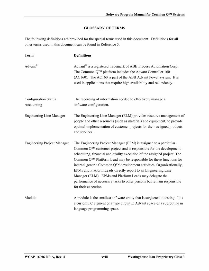
Software Program Manual for Common Q™ Systems
WCAP-16096-NP-A, Rev. 4 xviii Westinghouse Non-Proprietary Class 3
GLOSSARY OF TERMS
The following definitions are provided for the special terms used in this document. Definitions for all
other terms used in this document can be found in Reference 5.
Term Definitions
Advant® Advant® is a registered trademark of ABB Process Automation Corp.
The Common Q™ platform includes the Advant Controller 160
(AC160). The AC160 is part of the ABB Advant Power system. It is
used in applications that require high availability and redundancy.
Configuration Status The recording of information needed to effectively manage a
Accounting software configuration.
Engineering Line Manager The Engineering Line Manager (ELM) provides resource management of
people and other resources (such as materials and equipment) to provide
optimal implementation of customer projects for their assigned products
and services.
Engineering Project Manager The Engineering Project Manager (EPM) is assigned to a particular
Common Q™ customer project and is responsible for the development,
scheduling, financial and quality execution of the assigned project. The
Common Q™ Platform Lead may be responsible for these functions for
internal generic Common Q™ development activities. Organizationally,
EPMs and Platform Leads directly report to an Engineering Line
Manager (ELM). EPMs and Platform Leads may delegate the
performance of necessary tasks to other persons but remain responsible
for their execution.
Module A module is the smallest software entity that is subjected to testing. It is
a custom PC element or a type circuit in Advant space or a subroutine in
language programming space.

Software Program Manual for Common Q™ Systems
WCAP-16096-NP-A, Rev. 4 xix Westinghouse Non-Proprietary Class 3
GLOSSARY OF TERMS (cont.)
Term Definitions
Nuclear Automation Nuclear Automation is the cognizant engineering organization within
Westinghouse Electric Company that is responsible for the design and
implementation of Common Q™ based systems.
Platform Lead The Common Q™ Platform Lead is responsible for the platform
development meeting the continuing needs of the product family.
Project Plan A documented plan that identifies the information necessary to execute
the project, such as:
Overview of Project/System
General Functions of the Software
Project scope
Deliverables
Project milestones
Project stages
Project inputs and review
Key personnel and project interfaces including
— Internal
— Customer
— Supplier
Output review/verification/validation
Reference to detailed project schedule
Assumptions/Dependencies/Constraints/Risks
Methods, tools, and techniques
Performance measures
Security provisions
Software Lifecycle
Project Quality Plan (PQP) A document that specifies alternatives or supplements to the
Westinghouse QMS, Level 2, or Level 3 procedures as required to meet
contractual requirements or quality standards other than those specified
in the Westinghouse QMS. When the SPM refers to a PQP, it includes
the Project Quality Plan and Project Plan defined in the Westinghouse
Quality Procedures.

Software Program Manual for Common Q™ Systems
WCAP-16096-NP-A, Rev. 4 xx Westinghouse Non-Proprietary Class 3
GLOSSARY OF TERMS (cont.)
Term Definitions
Quality “Quality” is the generic title of any of the independent Quality Assurance
departments that are responsible for performing quality assurance
functions. Each business unit has a quality organization that is separate
from the engineering organization. The Quality organization provides
oversight by way of periodic audits to verify that the Nuclear
Automation organization is effectively implementing the Westinghouse
Quality Management System and its implementing procedures.
RTA The Requirements Traceability Analysis (RTA) is the task of ensuring
the completeness and accuracy of the RTM; all lower level requirements
and design features are derived from higher level requirements, and that
all higher level requirements are allocated to lower requirements, design
features, and tests. The traceability analysis also provides a method to
cross-reference each software requirement against all of the documents
and other software items in which it is addressed. The purpose of this
analysis is to verify that the design team addresses every requirement
throughout the design life cycle process. The IV&V team is responsible
for performing the RTA.
RTM The Requirements Traceability Matrix (RTM) is either a table of
information prepared manually, or a report generated from a
requirements database. The RTM associates requirements with the
documentation and software that satisfies them. Requirements are
entered in the matrix and are organized into successive lower level
requirements as described in each document. The requirements are then
traced through the software lifecycle to the design, code, and test
documentation. The design team is responsible for creating the RTM to
the point of identifying the code satisfying the requirement. IV&V will
complete the RTM identifying validation of the requirement.
SAP SAP is an enterprise software system used by Westinghouse Electric
Company to support its business processes by providing an integrated
data and process structure. It is provided by the German company
“Systems, Applications and Products in Data Processing.”

Software Program Manual for Common Q™ Systems
WCAP-16096-NP-A, Rev. 4 xxi Westinghouse Non-Proprietary Class 3
GLOSSARY OF TERMS (cont.)
Term Definitions
Secure Development Environment The condition of having appropriate physical, logical and
programmatic controls during the system development phases (i.e.,
concepts, requirements, design, implementation, testing) to ensure that
unwanted, unneeded and undocumented functionality (e.g., superfluous
code) is not introduced into digital safety systems.
Secure Operational Environment The condition of having appropriate physical, logical and
administrative controls within a facility to ensure that the reliable
operation of digital safety systems are not degraded by undesirable
behavior of connected systems and events initiated by inadvertent access
to the system.
Shall When used in a sentence, “shall” denotes a required action.
Should When used in a sentence, “should” denotes a recommended action.
Software Item A software item is defined as collection of source code modules, object
code modules, database modules, etc. which comprise the software
running in one identifiable computer. Since a system may have multiple
processors performing different functions, a system may have multiple
software items.
System A collection of components organized to accomplish a specific function
or set of functions. Components may be hardware or software units.
Testing The process of exercising or evaluating a system or system component
by manual or automated means, to verify that it satisfies specified
requirements or to identify differences between expected and actual
results.
Unit A unit consists of several modules that are integrated into a separately
testable element, logically consistent with design specifications. It is a
type circuit or control module in Advant space or a combination of
modules in language programming space.

Software Program Manual for Common Q™ Systems
WCAP-16096-NP-A, Rev. 4 xxii Westinghouse Non-Proprietary Class 3
REFERENCES
Following is a list of references used throughout this document. Unless stated otherwise, the latest
revision is applicable.
1. “Westinghouse Electric Company Quality Management System,” Westinghouse Electric Company
LLC.
2. ASME NQA-1-2008, Subpart 2.7, "Quality Assurance Requirements for Nuclear Facility
Applications"
3. Guidance on Evaluation and Acceptance of Commercial Grade Digital Equipment for Nuclear Safety
Applications, EPRI TR-106439, October 1996
4. Westinghouse Level II Policies & Procedures
5. IEEE Std 610.12-1990 (Reaffirmed 2002), “IEEE Standard Glossary of Software Engineering
Terminology.”
6. IEEE Std 830-1998, “IEEE Recommended Practice for Software Requirements Specifications”
7. IEEE Std 1016-1998, “Information Technology—Systems Design—Software Design Descriptions,”
8. IEEE Std 1012-1998, “IEEE Standard for Software Verification and Validation”
9. IEEE Std 1063-2001, “IEEE Standard for Software User Documentation”
10. IEEE Std 828-2005, “IEEE Standard for Software Configuration Management Plans”
11. IEEE Std 7-4.3.2-2003, “IEEE Standard Criteria for Digital Computers in Safety Systems of Nuclear
Power Generating Stations”
12. IEEE Std 1008-1987 (Reaffirmed 2002), “IEEE Standard for Software Unit Testing”

Software Program Manual for Common Q™ Systems
WCAP-16096-NP-A, Rev. 4 xxiii Westinghouse Non-Proprietary Class 3
REFERENCES (cont.)
13. IEEE Std 730-1998 “IEEE Standard for Software Quality Assurance Plans”
14. IEEE Std 829-1998, “IEEE Standard for Software Test Documentation”
15. IEEE Std 603-1991, “IEEE Standard Criteria for Safety Systems for Nuclear Power Generating
Stations”
16. IEEE Std 1028-1997, “IEEE Standard For Software Reviews”
17. Reg. Guide 1.152, Rev. 3 (July 2011), “Criteria for Digital Computers in Safety Systems of Nuclear
Power Plants”
18. Reg. Guide 1.168, Rev. 1 (Feb. 2004), “Verification, Validation, Reviews, and Audits for Digital
Computer Software used in Safety Systems of Nuclear Power Plants”
19. Reg. Guide 1.169, Rev. 0 (Sept. 1997), “Configuration Management Plans for Digital Computer
Software used in Safety Systems of Nuclear Power Plants”
20. Reg. Guide 1.170, Rev. 0 (Sept. 1997), “Software Test Documentation for Digital Computer Software
used in Safety Systems of Nuclear Power Plants”
21. Reg. Guide 1.171, Rev. 0 (Sept. 1997), “Software Unit Testing for Digital Computer Software used in
Safety Systems of Nuclear Power Plants”
22. Reg. Guide 1.172, Rev. 0 (Sept. 1997), “Software Requirements Specifications for Digital Computer
Software used in Safety Systems of Nuclear Power Plants”
23. Reg. Guide 1.173, Rev. 0 (Sept. 1997), “Developing Software Life Cycle Processes For Digital
Computer Software Used In Safety Systems Of Nuclear Power Plants”
24. IEEE Std 1074-1995, “IEEE Standard for Developing Software Life Cycle Processes”
25. IEC-60880, Nuclear power plants – Instrumentation and control systems important to safety –
Software aspects for computer-based systems performing category A functions – Edition 2.0
26. IEEE Std 1228-1994 (Reaffirmed 2002), “IEEE Standard For Software Safety Plans”

Software Program Manual for Common Q™ Systems
WCAP-16096-NP-A, Rev. 4 xxiv Westinghouse Non-Proprietary Class 3
REFERENCES (cont.)
27. NUREG-0800, Standard Review Plan for the Review of Safety Analysis Reports for Nuclear Power
Plants, Chapter 7, “USNRC Standard Review Plan for the Review of Safety Analysis Reports for
Nuclear Power Plants,” U.S. Nuclear Regulatory Commission, Revision 6, March 2010.
28. NUREG/CR-6430, “Software Safety Hazard Analysis”
29. ISO 90003, “Software engineering Guidelines for the application of ISO 9001:2000 to computer
software”
30. (Reference Deleted)
31. WCAP-7211, “Proprietary Information and Intellectual Property Management Policies and
Procedures,” Westinghouse Electric Company LLC.
32. NUREG/CR-6101, “Software Reliability and Safety in Nuclear Reactor Protection Systems,”
U.S. Nuclear Regulatory Commission
33. WCAP-17266-P, “Common Q Platform Generic Change Process,” Westinghouse Electric Company
LLC.
34. ASME NQA-1a-2009, "Addenda to ASME NQA-1-2008 Quality Assurance Requirements for
Nuclear Facility Applications"

Software Program Manual for Common Q™ Systems
WCAP-16096-NP-A, Rev. 4 xxv Westinghouse Non-Proprietary Class 3
DOCUMENTATION REQUIREMENTS
Documentation requirements have been identified in this document. The following table identifies
documents that are required by this SPM.
Table I. Document Requirements
Item Title Prepared By1
1 Audit Report (In-Process Audit) Quality
2 Certificate of Conformance (System) Quality
3 Code Review Report Independent Reviewer from either the
Design Team or IV&V Team
4 Coding Standards and Guidelines Design Team
5 Commercial Grade Dedication Report Design Team
6 Exception Report (Database) IV&V Team or Design Team
7 Exception Report Log (Database) IV&V Team or Design Team
8 Failure Modes and Effects Analysis Design Team
9 Safety Classification Record Design Team
10 Software Hazards Analysis Report Design Team
11 Project Plan Design Team
12 Project Quality Plan Design Team
13 Project Schedule Design Team
14 Purchase Order Customer
15 Regression Analysis Design Team or IV&V Team
16 Requirements Traceability Matrix (Database) Design Team
17 Resource Plan EPM
18 Software Change Request (Database) Design Team or IV&V Team
19 Software Change Request Log (Database) Design Team or IV&V Team
20 Software Design Description Design Team

Software Program Manual for Common Q™ Systems
WCAP-16096-NP-A, Rev. 4 xxvi Westinghouse Non-Proprietary Class 3
Table I. Document Requirements (cont.)
Item Title Prepared By1
21 Software Release Record Design Team
22 Software Requirements Specification Design Team
23 System Requirements Specification Design Team
24 Technical Bulletin ELM, EPM, or Platform Lead
25 Technical Manual Design Team
26 Test Plan IV&V Team or Design Team
27 Test Procedure (Module, Unit, Factory/Site
Acceptance)
IV&V Team or Design Team
28 Test Report (Module, Unit, Factory/Site
Acceptance)
IV&V Team or Design Team
29 Training Material Design Team
30 Training Record Each Employee
31 IV&V Report (Phase Summary/Final) IV&V Team
Notes:
1. See Exhibit 5-1 for document preparation responsibilities.
Information requirements have been identified in this document. The following table contains the section
number where the requirement is identified, a description of the requirement, and the output document
where the information should be located.
Table II. Information Requirements
SPM
Section
Number Description of Requirement Output Document
1.4.2 Training Record For SPM Training Record
3.1.2 Defining Acceptable Risks Project Plan
3.3.2 A detailed schedule Project Plan

Software Program Manual for Common Q™ Systems
WCAP-16096-NP-A, Rev. 4 xxvii Westinghouse Non-Proprietary Class 3
Table II. Information Requirements (cont.)
SPM
Section
Number Description of Requirement Output Document
3.3.2 Resource Plan Project Plan
3.3.5.10 Software User Documentation Technical Manual
3.3.5.11 Results of Software Safety Requirements
Analysis
IV&V Report
3.3.5.12 Results of Software Safety Design Analysis IV&V Report
3.3.5.13 Results of Software Safety Code Analysis IV&V Report
3.3.5.14 Results of Software Safety Test Analysis IV&V Report
3.3.5.15 Results of Software Safety Change Analysis IV&V Report
3.3.6 Software Hazards Software Hazards Analysis Report
3.3.6 Results of IV&V Analyses IV&V Report
3.3.6 Information on suspected or confirmed safety
problems
IV&V Report
3.3.6 Results of audits performed on software safety
program tasks
Audit Report
3.3.6 Results of safety tests conducted on the system Test Reports
3.3.6 Training Records Training Record
3.3.6 Software Safety Certification – Code
Certificate
IV&V Report
3.3.6 Tracking system to confirm hazards and their
statuses are tracked throughout software life
cycle
Requirements Traceability Matrix
3.3.10 Project Manager approves the use of any tool –
approval implicit by listing tool in Plan
Project Plan
3.4.1 Software Hazards Analysis Software Hazards Analysis Report
3.4.2 Software Safety Requirements Analysis IV&V Report

Software Program Manual for Common Q™ Systems
WCAP-16096-NP-A, Rev. 4 xxviii Westinghouse Non-Proprietary Class 3
Table II. Information Requirements (cont.)
SPM
Section
Number Description of Requirement Output Document
3.4.3 Software Safety Design Analysis IV&V Report
3.4.4 Software Safety Code Analysis IV&V Report
3.4.5 Software Integration Safety Analysis IV&V Report
3.4.6 Software Safety Test Analysis IV&V Report
3.4.7 Software Installation Safety Analysis IV&V Report
3.4.8 Software Safety Change Analysis IV&V Report
3.5 Training in SPM Section 11 Training Record
3.5.1 Review of Training Materials IV&V Report
3.5.1 Personnel Training Training Record
3.5.2.1 Review of Installation documentation IV&V Report
3.5.2.2 Software Installation and Startup Procedure Technical Manual
3.5.3 Procedures to verify software integrity to detect
unauthorized modification of code or data
Technical Manual
4.1.1 Documenting Software Classification Safety Classification Record
4.1.2 Commercial Grade Dedication Commercial Grade Dedication Report
4.3.2.1 Quality Assurance Planning Project Quality Plan
4.3.2.4 Verification of module code listings Code Review Reports
4.3.2.6 Exception Report Log Exception Report Database
4.3.2.6 Exception Report Exception Report Database
4.5.1 Work Instructions Any document required to supplement
the SPM (such as Coding Standards
and Guidelines Document)
4.5.2.1 Coding Standards Coding Standards and Guidelines
Document

Software Program Manual for Common Q™ Systems
WCAP-16096-NP-A, Rev. 4 xxix Westinghouse Non-Proprietary Class 3
Table II. Information Requirements (cont.)
SPM
Section
Number Description of Requirement Output Document
4.5.2.4 Metric Reporting Test Reports
4.6.2.1 Software Requirements Review IV&V Report
4.6.2.2.1 Architecture Design Review IV&V Report
4.6.2.2.2 Critical Design Review IV&V Report
4.6.2.3 Code Certification Code Review Reports
4.6.2.4 SVVP Review SPM
4.6.2.5 Functional Review IV&V Report
4.6.2.6 Physical Review IV&V Report
4.6.2.7 In-process Audits Audit Report
4.6.2.8 Managerial Reviews Audit Report
4.6.2.9 Software Configuration Management Plan
Review
IV&V Report
4.6.2.10 Post Mortem Review CAPs (IBM® Lotus Notes® Database)
5.1.4 Project-Specific IV&V Plan Activities Project Plan
5.4.5.2 IV&V Checklists IV&V Report
5.4.5.2 Review Changes to COTS software Commercial Grade Dedication Report
5.4.5.3 Requirements Traceability Analysis RTM or Requirements Management
Database
5.4.5.4 Database reviews (see also 5.5.5.2 #5) Implementation Phase Checklist in
IV&V Report
5.5.1 Baseline Change Assessment Regression Analysis
5.5.3.2 Software Safety Analyses IV&V Report
5.5.4.2 Software Safety Design Analyses IV&V Report
5.5.5.2 Software Safety Code Analyses IV&V Report

Software Program Manual for Common Q™ Systems
WCAP-16096-NP-A, Rev. 4 xxx Westinghouse Non-Proprietary Class 3
Table II. Information Requirements (cont.)
SPM
Section
Number Description of Requirement Output Document
5.5.6 Software Safety Test Analysis Test Phase Checklist in IV&V Report
5.5.6.3 Code Certificate IV&V Report
5.5.7.1 Installation Procedures, System Generation
Procedures, User Documentation
Technical Manual
5.5.7.2 Training Material Training Program Per Customer
Requirements
5.5.8 Regression Analysis IV&V Report or separately prepared
document
5.6.1 Discrepancy Reports Exception Record Database; Status
defined in IV&V Report
6.2.2.1 Identify original software items developed
under this SPM for generic application that are
to be controlled via SCM
Project Quality Plan
6.2.2.3 Define software items which are to be
controlled via SCM
Project Plan
6.3.2 Master list of software under configuration
control for a project
Configuration Management Release
Report
6.3.2 Software Change Request Database
6.3.2 Software Change Request Log Database
6.3.3 Configuration Status Accounting Configuration Management Release
Report
9.3.2.1 Feasibility Analysis Project Quality Plan
9.3.2.2 Detailed Analysis SysRS, SRS, Test Plan, PQP
9.5.2.4 Risk Analysis Project Quality Plan
11.2 Justification for not performing complete
system retesting
Regression Analysis in Exception
Report or SCR
Software Program Manual for Common Q™ Systems
WCAP-16096-NP-A, Rev. 4 xxxi Westinghouse Non-Proprietary Class 3
Table II. Information Requirements (cont.)
SPM
Section
Number Description of Requirement Output Document
11.2 Exception Reports Database
(Last Page of Front Matter)

Software Program Manual for Common Q™ Systems
WCAP-16096-NP-A, Rev. 4 1-1 Westinghouse Non-Proprietary Class 3
SECTION 1 INTRODUCTION
1.1 PURPOSE
Computer software is essential to the design, analysis, operation and control of Common Qualified (Q)
systems. This Software Program Manual (SPM) describes the requirements for the software design and
development process including the software/hardware interface. The SPM also describes the
requirements for the use of software in Common Q™ systems. The SPM expands the procedural
requirements for computer software in the Westinghouse Level II Policies and Procedures (Reference 4).
This manual is compliant with (ASME) NQA-1-2008 (Reference 2), Subpart 2.7, (ASME) NQA-1a-2009
(Reference 34), and ISO 90003 (Reference 29).
The Requirements for the Common Q™ hardware design process are defined in Reference 4. Hardware
verification is performed as part of the hardware quality assurance activities that are also defined in
Reference 4.
The Software Program Manual consists of several basic elements:
1. A Software Safety Plan, which identifies the processes that, will reasonably assure that
safety-critical software does not have hazards that could jeopardize the health and safety of the
public.
2. A Software Quality Assurance Plan (SQAP), which describes the process and practice of
developing and using software. The SQAP addresses standards, conventions, reviews, exception
reporting and other software quality issues.
3. A Software Verification and Validation Plan, which describes the method of assuring
correctness of the software.
4. A Software Configuration Management Plan, which describes the method of maintaining the
software in an identifiable state at all times.
5. A Software Test Plan, which describes the method for testing software.
6. A Software Installation Plan, which describes the method for installing software.
7. A Software Maintenance Plan, which describes software practices after delivery to a customer.

Software Program Manual for Common Q™ Systems
WCAP-16096-NP-A, Rev. 4 1-2 Westinghouse Non-Proprietary Class 3
8. A Secure Development and Operational Environment Plan, which provides reasonable
assurance that Common Q™ Systems and the development environments in which they are
created are protected from inadvertent operator actions and undesirable behavior of connected
systems.
The SPM also discusses Software Management, documentation and other matters related to software
design and use.
It is intended that this SPM be consistent with NRC regulatory positions taken with respect to specific
IEEE standards. These regulatory positions are documented in the Standard Review Plan (NUREG-0800)
and its associated Branch Technical Positions and Regulatory Guides.
EXHIBIT 1-1 RELATIONSHIP OF SPM TO IEEE STANDARDS shows how the IEEE standards are
applied to various Common Q™ design and quality assurance activities. The block labeled System
depicts IEEE Standard 603 (Reference 15) and IEEE Standard 7-4.3.2 (Reference 11), that support
systems development. The former addresses computer and non-computer hardware elements while the
latter addresses system-level issues for software. The block labeled Design Output Activities shows the
various software design activities and the specific IEEE standards that support those activities. IEEE Std
1074 (Reference 24) as endorsed by RG 1.173 (Reference 23) addresses the development of software life
cycle processes, and therefore serves to unify the individual activity standards. It also addresses
assurance activities, referred to by IEEE Std 1074 as “integral processes.” These are shown on the
bottom of the exhibit.
1.2 SCOPE
1.2.1 Software Classification and Categorization
This SPM shall apply to all software and firmware, whether developed in-house, licensed or procured
from a commercial vendor, obtained from another organization or otherwise acquired and used in a
Common Q™ system for delivery to a customer.
The Common Q™ software systems and software modules are identified as belonging to one of the
following classes:
Protection (safety critical – critical performance of the system). Software whose function is
necessary to directly perform RPS control actions, ESFAS control actions, and safe shutdown
control actions (Meets 10 CFR 50 Appendix B requirements).
Important-to-Safety (important system performance). Software whose function is necessary to
directly perform alternate protection system control actions or software that is relied on to

Software Program Manual for Common Q™ Systems
WCAP-16096-NP-A, Rev. 4 1-3 Westinghouse Non-Proprietary Class 3
monitor or test protection functions, or software that monitors plant critical safety functions
(Meets 10 CFR 50 Appendix B requirements).
Important-to-Availability. Software that is relied on to maintain operation of plant systems and
equipment that are critical to maintaining an operating plant.
General Purpose. Software that performs some purpose other than that described in the previous
classifications. This software includes tools that are used to develop software in the other
classifications, but is not installed in the online plant system. Examples of commercially
dedicated General Purpose software include compilers, assemblers, linkers, comparators, and
editors. Examples of Westinghouse developed General Purpose software include test case
generators, and test tools (e.g., I/O Simulator).
The requirements for the classification of functions, systems and equipment are provided in Reference 4.
The classifications of the system functional level are shown in EXHIBIT 4-1 ASSIGNMENT OF
COMMON Q™ SOFTWARE TO CLASSES.
The SPM makes distinctions regarding the methods applied to each of the above classes. Specific parts of
the software in a single system may be assigned to different classes. Each part of the software must have
an assigned class. Common Q™ applications not listed in EXHIBIT 4-1 ASSIGNMENT OF COMMON
Q™ SOFTWARE TO CLASSES shall document the software classification using the Safety
Classification Record in accordance with the requirements of Reference 4.
The SPM makes distinctions regarding methods applied to each of the following categories of Common
Q™ software:
Original, Developed for a Common Q™ System
Existing, to be Modified
Existing, to be used as is
Software in several categories may be included in each Common Q™ system. For example, a typical
computer system may rely on:
An operating system from a commercial supplier that is existing, used as is.
Some residual code to be updated from a previous project (existing, to be modified)
New algorithms (originally developed)
This SPM applies to all software used in the development, testing or delivered Common Q™ systems.

Software Program Manual for Common Q™ Systems
WCAP-16096-NP-A, Rev. 4 1-4 Westinghouse Non-Proprietary Class 3
1.2.2 Software Exclusions
The following software is excluded from the requirements of this SPM:
Administrative software used for purposes such as ordering, scheduling and project
management.
Commercial applications software for use in database management systems, word processing,
and commercially purchased CAD systems. Such applications are Microsoft® Excel®, Microsoft
Word®, and AutoCAD® software.
1.3 OVERVIEW
Common Q™ software developers shall proceed through a software development effort by following the
approach described in this manual.
The Software developers shall first become familiar with the Software Quality Assurance Plan (SQAP,
Section 4). All activities relating to Common Q™ software development and maintenance shall be
performed in accordance with the requirements contained in the SQAP.
The Engineering Project Manager (EPM) is required to determine the class and category of all software to
be used for the Common Q™ system as described in the SQAP. The EPM is also required to identify the
applicable standards that must be followed for those specific classes and categories of software. This
information shall be documented. The software tasks and responsibilities are outlined in the SQAP based
upon software classification and category.
Each quality assurance task is described in the SQAP for each software life cycle phase. The narrative
description, along with the corresponding Exhibit, assist the EPM in making the required decisions
concerning the appropriate tasks to be performed and who is responsible for performing them. In
addition, the specific documents that must be produced for each software life cycle phase are discussed in
the SQAP. Required documents vary for each software category.
The Software Verification and Validation Plan and the Software Configuration Management Plan
describe the details of some of the activities outlined in the SQAP.
Adherence to the Software Verification and Validation Plan (Section 5) will verify the accurate
translation from one step in the software development process to the next step and the validation that the
software product fulfills the requirements for which the software was developed. The degree of
independence required by this plan varies with the software classification. The applicability of the tasks
varies with the software category. The general definition of and qualifications for reviewer independence
are stated in Reference 4.

Software Program Manual for Common Q™ Systems
WCAP-16096-NP-A, Rev. 4 1-5 Westinghouse Non-Proprietary Class 3
The Software Configuration Management Plan (Section 6) describes the procedures necessary to maintain
the Common Q™ software in an identifiable state at all times. These procedures do not vary with the
software class or category.
The Software Test Plan (Section 7) describes the testing process for Common Q™ safety systems. This
plan identifies testing activities and test documentation required to verify and validate a Common Q™
safety system throughout the software life cycle.
The Software Installation Plan (Section 8) describes the method for installing operating system software
and application software onto the processor module, and the method for installing operating system
software and application software into the Flat Panel Display System.
The Software Maintenance Plan (Section 9) describes the activities necessary to maintain the Common
Q™ software, to remove errors, to respond to new or revised requirements and to adapt the software to
changes in operating environments.
The Documentation section (Section 10) of this Software Program Manual describes the various
documents that are required. The set of required documents for each software class is specified in the
Software Quality Assurance Plan.
The Problem Reporting and Corrective Action section (Section 11) of the Software Program Manual
describes procedures necessary to track that all software errors and failures are promptly acted upon and
in a uniform manner encompassing all Common Q™ software. The procedures in this section tie together
the requirements of the Software Verification and Validation Plan and the Software Configuration
Management Plan.
The Secure Development and Operational Environment Plan (Section 12) provides reasonable assurance
that Common Q™ Systems and the development environments in which they are created are protected
from inadvertent operator actions and undesirable behavior of connected systems.
1.4 GENERAL REQUIREMENTS
The management and control of software applies to computer software and associated documentation
developed or used for Common Q™ applications. Software shall be developed, acquired, procured,
controlled, and maintained in accordance with this Software Program Manual. Any software developed
under a different program than this SPM will go through a Commercial Grade Dedication process, which
evaluates the development of that software to the requirements of the SPM. A Commercial Grade
Dedication Report will be produced for this software. The SPM meets the requirements of Reference 11
as augmented by Reference 17 for Protection class software. See EXHIBIT 5-1 SOFTWARE TASKS
AND RESPONSIBILITIES for the requisite activities for Important-to-Safety class software.
Software Program Manual for Common Q™ Systems
WCAP-16096-NP-A, Rev. 4 1-6 Westinghouse Non-Proprietary Class 3
1.4.1 Software Life Cycle
The Software Life Cycle used in this SPM is based on information contained in References 2 and 24. The
Software Life Cycle phases are:
Concept
Requirements Analysis
Design
Implementation or Coding
Test
Installation and Checkout
Operation and Maintenance
Retirement
These phases may overlap or be performed iteratively. If the phases overlap, each phase shall be
completed before any subsequent phase is completed.
1.4.2 Indoctrination and Training
Personnel involved in Common Q™ software design and development shall have documented training in
this SPM. Such training records shall be prepared and maintained in accordance with the requirements of
Reference 4.
(Last Page of Section 1)

Software Program Manual for Common Q™ Systems
WCAP-16096-NP-A, Rev. 4 2-1 Westinghouse Non-Proprietary Class 3
SECTION 2 ORGANIZATION
Reference 1 defines the Westinghouse Quality Policy, which is to provide products and services that fully
satisfy customer and regulatory requirements. The Westinghouse President and CEO defines the overall
quality policy and promotes a culture of conformance to requirements, customer satisfaction and
continual improvement. Organizations reporting to the Westinghouse President and CEO are assigned
responsibilities for contractual requirements being identified and met, a focal point for achieving
customer satisfaction, and the quality of items and services. These organizations include functions such
as Engineering, Manufacturing, Project Management, Quality, Marketing, and Purchasing. Reference 1
provides typical operational organization reporting structures designed to satisfy the commitments of the
Quality Management System.
The methodology and procedures described in this SPM are implemented by the Nuclear Automation
(NA) organization. Within this organization, software activities are organized into the following two
teams:
The Design team performs software configuration management activities, develops the system
requirements, software design, and code for the Common Q™ systems. The design team may
also develop common software that is used in systems developed by other groups.
The IV&V team performs software design verification, software validation testing on the
Common Q™ systems. Depending on the software classification, the design team may perform
the validation testing activities.
Reference 11 requires that the IV&V team for a safety system is organized independently of the design
team. The NA organization meets this requirement by not allowing IV&V team members to participate
on the design team, even on a part time basis. EXHIBIT 2-1 DESIGN/IV&V TEAM ORGANIZATION
shows the relationship between the design team and the IV&V team. The IV&V team reports to an
Engineering Line Manager (ELM) who is administratively and financially independent from the design
team manager.
Team leaders are assigned specific responsibilities and the authority to assure the accomplishment of
software management and control through written plans, procedures, standards, and instructions.
The Engineering Project Manager (EPM) is the manager of the group responsible for control of a software
configuration item. The EPM may delegate the performance of necessary tasks to other persons but
remains responsible for their execution. The EPM is ultimately responsible and accountable for:

Software Program Manual for Common Q™ Systems
WCAP-16096-NP-A, Rev. 4 2-2 Westinghouse Non-Proprietary Class 3
Plans, schedules, procedures, methods, and techniques required in the technical and
administrative performance of the Common Q™ related software.
Compliance with this Software Program Manual.
The overall effectiveness of the implementation of the SPM is evaluated by the Westinghouse Quality
organization in accordance with the internal audit requirements of Reference 4.
(Last Page of Section 2)

Software Program Manual for Common Q™ Systems
WCAP-16096-NP-A, Rev. 4 3-1 Westinghouse Non-Proprietary Class 3
SECTION 3 SOFTWARE SAFETY PLAN
3.1 INTRODUCTION
3.1.1 PURPOSE
The goal of this safety plan is to enable the development of safety critical software for Common Q™
Systems that has reasonable assurance that software defects do not present severe consequences to public
health and safety.
3.1.2 SCOPE
The safety objective of this plan is to provide procedures and methodologies for the development,
procurement, maintenance, and retirement processes of Common Q™ safety critical software to mitigate
the potential of a software defect jeopardizing the health and safety of the public.
Any acceptable risks and safety objectives specific to a project shall be defined in the specific Project
Plan for a given system implementation.
This plan is prepared in accordance with Reference 27, Branch Technical Position (BTP) 7-14, "Guidance
on Software Reviews for Digital Computer-Based Instrumentation and Control Systems", and Reference
32. It applies to all Common Q™ safety critical software whose failure could result in severe
consequences to public health and safety. For Common Q™ systems, safety critical software is defined
as software belonging to the “Protection” class as defined in Section 1.
3.2 DEFINITIONS, ACRONYMS, ABBREVIATIONS, AND REFERENCES
Refer to page xv for a list of acronyms and trademarks. Refer to page xviii for definitions. Refer to page
xxii for a list of references.
3.3 SOFTWARE SAFETY MANAGEMENT
In compliance with Reference 32, this section provides a description of the software safety organization,
and the management of software safety activities and safety analysis requirements.
3.3.1 Organization and Responsibilities
Section 2 defines the organization that is responsible for design and implementation of Common Q™
Protection software.

Software Program Manual for Common Q™ Systems
WCAP-16096-NP-A, Rev. 4 3-2 Westinghouse Non-Proprietary Class 3
The software safety organization is composed of three parts:
1. The Quality organization, an independent quality assurance department, coordinates and reviews
quality assurance procedures and directives. The Quality organization has a reporting chain
separate from the design team such that the QA organization is independent of project schedule
and cost considerations. The Quality organization provides oversight by way of periodic audits to
verify that the NA organization is correctly abiding by both the procedures and directives
generated by both organizations. The Manager of the Quality organization, or designee, approves
this Software Program Manual which includes the Software Safety Plan.
2. An independent V&V team within the NA organization performs the safety activities for a given
Common Q™ system implementation project. Refer to subsection 5.4.3.2 for a description of the
IV&V team.
3. An Engineering VP reports directly to the Senior VP of NA. The design team ELM reports
directly to the Engineering Director.
The IV&V ELM shall have the following software safety responsibilities:
1. Confirm there is sufficient, independent, technically qualified and trained resources to implement
the requirements of this software safety plan. Training includes familiarizing the IV&V team
members with the methods, tools and techniques described in subsection 5.4.5.
2. Coordinate software safety task planning and implementation with the design team for the
activities in Section 5.
3. Verify that records are kept in accordance with Section 5 and Reference 4.
4. Support the QA department on any audits within the purview of its responsibilities.
The mechanism for communicating safety concerns, raised by project staff, to software safety personnel is
defined in Reference 4.
3.3.2 Resources
NA management shall develop an early understanding of the resources required to develop Protection
class software, so that these resources are put in place when they are required. The EPM and the IV&V
team leader shall determine the resources required to implement a Common Q™ system. ELMs shall
assign the appropriate resources to the EPM and IV&V team leader. The following resources are
considered for both the design and IV&V team:

Software Program Manual for Common Q™ Systems
WCAP-16096-NP-A, Rev. 4 3-3 Westinghouse Non-Proprietary Class 3
Personnel
Test materials and data
Computers and other equipment
Equipment support
Tools
Financial and schedule
The EPM shall maintain an up-to-date resource plan and assure that the resources are made available
when required.
Project schedules and resource allocations are established via the Project Plan.
3.3.3 Staff Qualifications And Training
The qualifications and training requirements for those personnel performing software safety functions are
primarily the same as those for performing the software design.
The following table identifies the personnel that will perform the tasks identified in Reference 32,
subsection 3.1.5:
Table 3.3.3-1. Software Safety Task Assignments
Task Assignee
Define safety requirements Design Team
Design and implement safety-critical portions of the system Design Team
Perform software safety analysis tasks IV&V Team
Test safety-critical features IV&V Team
Audit software safety plan implementation Quality organization
Perform process certification Quality organization (subsection 3.3.13)
One of the most important factors in developing reliable software is the development and use of a
qualified staff. In assessing the training requirements, the Engineering Line Manager considers that:
Training needs vary by individual
Training and retraining may be needed at various project phases
Staff qualification and training need to be periodically reassessed

Software Program Manual for Common Q™ Systems
WCAP-16096-NP-A, Rev. 4 3-4 Westinghouse Non-Proprietary Class 3
In addition to the above, the IV&V team shall be trained in the tools, techniques, and methodologies
described in subsection 5.4.5.
The ELMs assure that all personnel participating in the design, implementation, test and verification of
software are qualified to perform their assigned tasks. Since there is currently no industry sanctioned
certification program for Protection and Important-to-Safety class software personnel, the ELM assesses
the capabilities of candidates and selects appropriately qualified personnel based on the manager’s
experience.
In determining whether any candidate is qualified, the ELM considers whether the candidate:
Understands the system and its potentially hazardous effects, as described in Section 3.4
Understands the job to be performed
Has, or is capable of obtaining, working knowledge of system software and tools required to do
the job
Possesses the combination of skills and knowledge to perform the job; through a proper level of
formal education, supplemental training, and experience
Understands the related quality assurance, configuration management, and verification and
validation plans
Is able to produce reliable software, good documentation, and can implement required quality
assurance practices
Throughout a project, requirements and tasks may change. The ELM shall periodically reassess the
qualifications of all personnel working on Protection class software, particularly when specific changes to
the project become known. The ELM may direct additional training before the changes are effective, in
order to staff a fully qualified project team.
Personnel performing software safety reviews shall meet the qualifications for an independent reviewer,
as defined in Reference 4.
3.3.4 Software Life Cycle
The software life cycle to be implemented for Common Q™ system development activities including
IV&V is defined in subsection 1.4.1. Section 3.4 describes the relationship among specific software
safety analysis tasks and the associated activities for each phase of the software life cycle.

Software Program Manual for Common Q™ Systems
WCAP-16096-NP-A, Rev. 4 3-5 Westinghouse Non-Proprietary Class 3
3.3.5 Documentation Requirements
The documentation for Common Q™ software shall be prepared in accordance with the requirements in
Section 10, and incorporates the software safety documentation requirements. The change and approval
process for the Protection class software portions of project documentation is the same as for other
documentation as specified in Section 4.6.
3.3.5.1 Software Project Management
A Project Quality Plan, compliant with Reference 4 shall be developed that will coordinate both the
system development, software safety and quality assurance activities to identify the prescribed procedures
and provide the adequate, allocated resources for their proper execution.
3.3.5.2 Software Configuration Management
Section 6 contains the requirements for software configuration management. Any deviations to these
requirements shall be documented in the project specific Project Quality Plan. Section 6 defines specific
SCM responsibilities for a Common Q™ project and covers each phase of the software life cycle.
3.3.5.3 Software Quality Assurance
Section 4 is the Software Quality Assurance Plan (SQAP) that describes the requirements and
methodology to be followed in developing, acquiring, using and maintaining safety-critical software.
This SQAP is compliant to Reference 13.
3.3.5.4 Software Safety Requirements
The system requirements documentation (Section 10.2) specifies the safety requirements to be met by the
software to avoid or control system hazards.
3.3.5.5 Software Design Description
The Software Design Description (SDD, Section 10.3) includes descriptions of the software design
elements that satisfy the software safety requirements.
3.3.5.6 Software Development Methodology, Standards, Practices, Metrics and Conventions
The standards, practices, conventions and metrics to be applied to the Common Q™ project are defined in
Section 4.5.

Software Program Manual for Common Q™ Systems
WCAP-16096-NP-A, Rev. 4 3-6 Westinghouse Non-Proprietary Class 3
3.3.5.7 Test Documentation
Test documentation includes test plans, test procedures and test reports. Test procedures incorporate test
design and test cases.
3.3.5.7.1 Test Plans
The test plans provide a high level description of all tests that will be conducted for the Common Q™
project. They shall contain the requirements for all acceptance test procedures and define each required
test to be conducted. They also define the methodology for the disposition of test exceptions (errors).
This document is verified against the outputs generated from the requirements phase of IV&V for
completeness. All prerequisites for testing shall also be identified. Subsection 4.3.2.2 describes the
requirements for a test plan.
3.3.5.7.2 Test Procedures
The test procedures are the instructions for the actual tests conducted on the Common Q™ software.
They include test setup, precautions and limitations, and the test cases used to validate proper operation.
The test procedures are verified against both the test plan and outputs generated from the requirements
phase of IV&V. Refer to subsection 5.5.6 for a description of test procedure contents.
3.3.5.7.3 Test Reports
The test reports document the execution of the acceptance test procedures. In addition to attaching the
signed and checked off test procedure, the test reports provide an overall summary of the test results and
the resulting Exception Reports generated during the test. The system configuration at the time of test
execution is also documented in the test reports. Test Reports are prepared in accordance with Reference
14, Section 11.
3.3.5.8 Software Verification and Validation
The Software IV&V documentation is described in Section 5.
3.3.5.9 Reporting Safety Verification and Validation
IV&V reporting is described in Section 5.
3.3.5.10 Software User Documentation
User documentation is described in Section 10.6.

Software Program Manual for Common Q™ Systems
WCAP-16096-NP-A, Rev. 4 3-7 Westinghouse Non-Proprietary Class 3
3.3.5.11 Results of Software Safety Requirements Analysis
The results of the Software Safety Requirements Analysis as described in subsection 3.4.2 below shall be
documented in the Requirements Phase section of the IV&V Report (Section 10.5).
3.3.5.12 Results of Software Safety Design Analysis
The results of the Software Safety Design Analysis as described in subsection 3.4.3 below shall be
documented in the Design Phase section of the IV&V Report (Section 10.5).
3.3.5.13 Results of Software Safety Code Analysis
The results of the Software Safety Code Analysis as defined in subsection 3.4.4 below shall be found in
the IV&V Report for the Implementation Phase of the software life cycle. Any changes will be
documented in either IV&V Discrepancy Reports or as suggestions in the IV&V Report.
3.3.5.14 Results of Software Safety Test Analysis
The results of the Software Safety Test Analysis as defined in subsection 3.4.6 below shall be found in
the IV&V Report for the Testing Phase of the software life cycle.
3.3.5.15 Results of Software Safety Change Analysis
The results of the Software Safety Change Analysis as defined in subsection 3.4.8 below shall be found in
the IV&V Report. For each software life cycle that is revisited by the design team, the IV&V team will
analyze the impact on the previous life cycle phase as well as the phase it is analyzing. The results of
each phase’s analysis will be found in the IV&V Report for that software life cycle phase.
3.3.6 Software Safety Program Records
Records generation and maintenance procedures required for Common Q™ software are described
throughout this Software Program Manual. Originals of issued documents for Common Q™ software are
maintained according to Section 10.
Before the software requirements phase is completed and after the overall system design is known, an
evaluation is made to determine the safety critical hazards posed by the system through its interfaces. The
analysis assumes that a worst case scenario of possible errors (hardware or software) has occurred in the
system. Based on this assumption, the analysis results in an identification of system malfunctions that are
injurious to public health and safety.

Software Program Manual for Common Q™ Systems
WCAP-16096-NP-A, Rev. 4 3-8 Westinghouse Non-Proprietary Class 3
For each hazard identified above, the analysis further determines whether a software malfunction could
produce the hazardous condition. These software hazards are identified in the Software Hazards Analysis
Report as described in subsection 3.4.1. Each software producible hazard is evaluated during each phase
of development of the safety critical software. The Software Hazards Analysis Report is issued by the
Design Team and is an input to the IV&V team.
Results of IV&V analyses performed on requirements, design, code, test and other technical
documentation are documented in the IV&V Phase Summary Reports and the Final IV&V Report.
Information on suspected or confirmed safety problems in the prerelease or installed system is recorded in
the Final IV&V Report. Results of audits performed on software safety program tasks are documented in
the Quality organization’s Audit Report. Results of safety tests conducted on all or any part of the entire
system are documented in the Test Report. Training records are maintained by NA line management per
Reference 4. Software safety certification is documented in the Code Certificate.
Retention of software safety program records is in accordance with Reference 4. The initiation and
completion criteria for software safety program tasks for each phase in the software life cycle are defined
in Section 5.
The tracking system used to confirm that hazards and their status are tracked throughout the software life
cycle through retirement is the RTA and RTM as described in Section 5.
3.3.7 Software Configuration Management Activities
A key factor in developing reliable software is strict and detailed configuration management. Software
configuration management activities for Common Q™ software are described in Section 6.
3.3.8 Software Quality Assurance Activities
Software quality assurance activities for Common Q™ software are described in Section 4.
3.3.9 Software Verification and Validation Activities
Software verification and validation activities for Common Q™ software are described in Section 5.
These activities conform to the requirements in References 8 and 11.
3.3.10 Tool Support and Approval
Section 4.9 describes the use of software tools that are used in development of Common Q™ systems.
Tools may produce better program structure and more reliable software through the automation of
repetitive or time-consuming tasks. The EPM and IV&V team leader approve the use of any tool. This
Software Program Manual for Common Q™ Systems
WCAP-16096-NP-A, Rev. 4 3-9 Westinghouse Non-Proprietary Class 3
approval is based on an evaluation of the tool’s readiness for use on a project involving Protection class
software. This evaluation considers:
The tool’s past performance
The extent of tool validation already performed
The consistency of tool design with planned use
The use of tool upgrades
The retirement of tools
The restrictions on the use of the tool due to limitations
The inadvertent introduction of software hazards by project tools is mitigated by the proper use of
techniques for software configuration management, software quality assurance and IV&V as described in
this SPM.
3.3.11 Previously Developed or Purchased Software
Subsections 4.1.2, 4.12.1, and 5.5.3.2 describe the requirements for using existing software, including
purchased software, as safety critical software. WCAP-17266-P, “Common Q Platform Generic Change
Process,” (Reference 33) describes the change analysis for previously developed software to preserve the
safety integrity.
3.3.12 Subcontract Management
Subsection 4.12.2 specifies the provisions for ensuring that subcontractor software meets established
software safety program requirements.
3.3.13 Process Certification
An audit report from an In-Process Audit described in subsection 4.6.2.7 is prepared by the Quality
organization to document that the software related activities were performed in accordance with the
Quality Management System (Reference 1) and its implementing procedures.
3.4 SOFTWARE SAFETY ANALYSES
3.4.1 Software Safety Analyses Preparation
It is vitally important to understand the ways that a system could potentially present hazards to public
health and safety. The system design and review techniques described in this SPM are used to avoid,
preclude, or mitigate the impact of potential software hazards in systems built using the Common Q™
platform. Systems that include both Protection and Important-to-Safety class software need to postulate in

Software Program Manual for Common Q™ Systems
WCAP-16096-NP-A, Rev. 4 3-10 Westinghouse Non-Proprietary Class 3
the Software Hazards Analysis potential software hazards in the Important-to-Safety class software and
the impact on Protection class software.
A Software Hazards Analysis (SHA) will identify the following:
Hazardous System States. Before the software requirements phase is completed and after the
overall system design is known, an evaluation is made to determine the safety hazards posed by
the system through its interfaces that are injurious to public health and safety. The plant safety
analysis defines the safety-critical hazards (accidents) posed by the plant that may be injurious to
public health and safety. The failure modes and effects analysis performed for the specific
Common Q™ System analyzes the vulnerability to single failures at the hardware module level,
including existing compensating provisions (hazard controls) within the design of each system.
These two sources form the design bases for software safety requirements for the Common Q™
Safety System.
Sequences of actions that can cause the system to enter a hazardous state. For each
identified hazard, the analysis determines whether a software malfunction could produce the
hazardous condition, or the hazard could affect software operability. These hazards are
identified in the Software Hazards Analysis Report. Each software related hazard is evaluated
during each phase of development of the Protection class software. Reference 28 shall be used
as a guide in performing this analysis.
Sequences of actions intended to return the system from a hazardous state to a
non-hazardous state. For each hazardous state, the system design must account for returning
the system to a non-hazardous state. In preparing the Software Requirements Specification, the
software developer considers techniques that can avoid a hazardous condition, or return the
system to a non-hazardous state. The result of the requirements phase may be a set of required
or forbidden design, coding or testing techniques. The requirements phase may also identify
specific tests to be performed or the implementation of certain hazard recovery techniques.
The System Requirements Specification (subsection 10.2.1) provides the high-level system design as
required in subsection 4.4.1 b) of Reference 26. The interfaces between the software and the rest of the
system are defined in the Software Requirements Specification (subsection 10.2.2).
3.4.2 Software Safety Requirements Analysis
In preparing the Software Requirements, the software developer considers techniques that can avoid a
hazardous condition. The result of the requirements phase may be a set of required or forbidden design,
coding or testing techniques. The requirements phase may also identify specific tests to be performed or
the implementation of certain hazard recovery techniques.

Software Program Manual for Common Q™ Systems
WCAP-16096-NP-A, Rev. 4 3-11 Westinghouse Non-Proprietary Class 3
Refer to subsection 5.5.3 for a description of the software safety requirements analyses performed. These
activities provide reasonable assurance that each system safety requirement is satisfied by the software
safety requirements.
3.4.3 Software Safety Design Analysis
Refer to subsection 5.5.4 for a description of the software safety design analyses performed. These
activities provide reasonable assurance that each software safety requirement is satisfied by the software
safety design.
3.4.4 Software Safety Code Analysis
Refer to subsection 5.5.5 for a description of the software safety code analyses performed. These
activities provide reasonable assurance that each software safety design element is satisfied by the
software safety code.
3.4.5 Software Integration Safety Analysis
The software integration safety analysis is performed as part of the software safety test analysis. Refer to
subsection 3.4.6 for the software safety test analysis.
3.4.6 Software Safety Test Analysis
Refer to subsection 5.5.6 for a description of the software safety test analyses performed for module/unit
testing and system testing respectively. These activities provide reasonable assurance that each system
and software safety requirement is tested.
3.4.7 Software Installation Safety Analysis
Subsection 5.5.7 fulfills the requirements for a software installation safety analysis. This final safety
analysis verifies that the installed system operates correctly.
3.4.8 Software Safety Change Analysis
Subsection 5.5.8 and Section 9 fulfill the requirements for a software safety change analysis. These
activities provide reasonable assurance that changes to safety critical software do not create, impact a
previously resolved, or exacerbate a currently existing hazard, and does not adversely affect any safety-
critical software design elements.

Software Program Manual for Common Q™ Systems
WCAP-16096-NP-A, Rev. 4 3-12 Westinghouse Non-Proprietary Class 3
3.5 POST DEVELOPMENT
In spite of the best efforts by software personnel in developing reliable Protection class software,
inappropriate use or maintenance of the software may undo the software reliability by the recipient after
delivery. It is important that the recipient be trained and qualified to use or maintain the software.
Software personnel shall be trained in the procedures in Section 11 involving exception reporting and
correction.
3.5.1 Training
Common Q™ customers are responsible for providing safety training for the users, operators, and
maintenance and management personnel, as appropriate. All training materials prepared for Common
Q™ customers must be reviewed by the IV&V team per subsection 5.5.7
Westinghouse personnel assigned to work on any activity in the software life cycle process must complete
training on the SPM in accordance with Reference 4.
3.5.2 Deployment
3.5.2.1 Installation
Installation documentation shall be developed, prior to the installation and checkout phase of the software
life cycle, which will include the procedure(s) for installing the software. The IV&V team shall review
this documentation according to the procedure in subsection 5.5.7.
3.5.2.2 Startup and Transition
Changes to installed systems may be disruptive to operations, particularly if problems occur or the
resulting system operates differently. A Software Installation and Startup Procedure will be prepared
addressing the following (as appropriate to the configuration of the system being installed):
Fallback modes for the new system
Startup of Backup components and subsystems
Startup of the New system
Parallel operation with backups
Parallel operation of the old system and the new system
Subsystem vs. full system operation
Switchover to full system operation
Validation of results from the new system
Cross validation of results between the old system and the new system

Software Program Manual for Common Q™ Systems
WCAP-16096-NP-A, Rev. 4 3-13 Westinghouse Non-Proprietary Class 3
Fallback in the case of failure of the new system, including fallback to an old system if one exists
3.5.2.3 Operations Support
Documentation of the system and its software is supplied as described in Section 10. This documentation
includes design documents, user manuals and instructions for maintenance expected by plant personnel.
3.5.3 Monitoring
Problem Reporting and Corrective Action (Section 11) contains requirements for monitoring the use of
delivered software and associated exception reporting.
In addition, Protection class software is designed so that the integrity of the software can be verified
periodically to detect unauthorized modification of code or data. Procedures necessary to perform this
verification shall be documented. Methods shall be considered that provide automatic verification of the
system during operation.
3.5.4 Maintenance
Software changes during all software life cycles are executed according to the Software Configuration
Management Plan in Section 6 and the Software Maintenance Plan in Section 8.
3.5.5 Retirement and Notification
Subsection 6.2.2 describes the retirement of software and associated notification to current users.
(Last Page of Section 3)

Software Program Manual for Common Q™ Systems
WCAP-16096-NP-A, Rev. 4 4-1 Westinghouse Non-Proprietary Class 3
SECTION 4 SOFTWARE QUALITY ASSURANCE PLAN
4.1 INTRODUCTION
4.1.1 Purpose
The Software Quality Assurance Plan (SQAP) describes the requirements and methodology to be
followed in developing, acquiring, using, and maintaining software to be used for the design and
operation of Common Q™ systems. The SQAP complies with Reference 13.
Software to be developed and used for the Common Q™ systems shall be placed into the following
software classes (see subsection 1.2.1):
Protection (safety critical)
Important-to-Safety
Important-to-Availability
General Purpose
All software modules shall be developed or used consistent with the classifications shown in
EXHIBIT 4-1 ASSIGNMENT OF COMMON Q™ SOFTWARE TO CLASSES for PPS/RPS, ESFAS,
CPCS and PAMS. Common Q™ applications not listed in the exhibit shall document the software
classification using the Safety Classification Record in accordance with the Requirements of Reference 4.
Software that is initially assigned to one software class can be reassigned to another class provided that all
tasks appropriate for the new class, up to the current phase of the software life cycle, are completed and
satisfactorily reviewed. Changes in classification shall be documented via a Safety Classification Record
in accordance with Reference 4. The Safety Classification Records are prepared by the design
organization and are an input to the design and IV&V teams to determine the necessary requirements for
design and IV&V activities. The appropriateness of the software safety classification is reviewed
throughout the design and IV&V activities.
4.1.2 Scope
This SQAP is required for all quality classifications defined for the Common Q™ system: protection,
important-to-safety, important-to-availability, and general purpose software.
This SQAP is based on the software life cycle model described in Reference 5 for Software Lifecycle.
Within each software class described in subsection 4.1.1, there are categories of software, which this
SQAP addresses. These categories are described as follows:

Software Program Manual for Common Q™ Systems
WCAP-16096-NP-A, Rev. 4 4-2 Westinghouse Non-Proprietary Class 3
1. Original software
2. Existing software
a. To be modified
b. Not to be modified
Documentation requirements depend on the classification and category of software and shall be consistent
with EXHIBIT 4-1 ASSIGNMENT OF COMMON Q™ SOFTWARE TO CLASSES and EXHIBIT 4-3
TASKS REQUIRED FOR SOFTWARE CATEGORIES.
Existing software is software that has been created, but not under this SPM. To qualify for use under this
SPM, the software must be evaluated by the design team to meet the following criteria:
Existing commercial software may be used in protection and important-to-safety applications if
it is qualified using a Commercial Grade Dedication Program (CGDP) such as the one described
in Reference 3. To qualify existing commercial important-to-availability or general purpose
software, the design team shall select applicable portions of the CGDP and qualify the software
to those portions.
Existing NPP non-commercial software that has been actively used in a nuclear power plant may
be used for the same class of software under this SPM provided it has been maintained under an
acceptable quality plan with an active program for problem and corrective action reporting. This
software shall also have adequate design documentation, user documentation and
well-commented source code. This software shall have been verified and validated under
another program that is judged by the IV&V team to be acceptable.
Other existing non-commercial software (i.e., source code freely available (e.g., freeware)) may
be used under the following conditions:
— This software can only be qualified as Important-to-Safety, Important-to-Availability, or
General Purpose software.
— The software fulfills a specific requirement identified in the Software Requirements
Specification (SRS).

Software Program Manual for Common Q™ Systems
WCAP-16096-NP-A, Rev. 4 4-3 Westinghouse Non-Proprietary Class 3
— The code is well organized and has adequate design documentation, and source code
commentary. If the software has poor or no documentation then, documentation shall be
prepared.
— Will undergo the IV&V process starting at the implementation phase.
For existing software that is qualified as above, design documentation and code may be used without
revision to meet format or content requirements of this SPM. Modifications to this software may be made
in accordance with prior documentation and code format.
Under this SQAP, a software product that is contracted for development by a subcontractor is treated as
original software unless the software already exists and is in use. In this case, it is treated as existing
software.
This SQAP describes the methodology by which all software and associated documentation is managed
throughout the life cycle. Software elements produced in the process of quality assurance are as follows:
Test plans, cases, procedures and reports
Review and audit results
Exception reports and corrective action documentation
Software configuration management plans
Software verification and validation plans
4.1.3 Software Development Process
The software development process for original software is shown in EXHIBIT 4-2 COMMON Q™
SOFTWARE DEVELOPMENT PROCESS. This exhibit shows the relationship between software and
hardware, the process of software integration and testing, the design documentation produced, and the
quality assurance documentation required throughout the software life cycle.
As shown in EXHIBIT 4-2 COMMON Q™ SOFTWARE DEVELOPMENT PROCESS, software quality
is assured through the process of verification reviews, validation testing at the different stages of
development, and software configuration management during all phases of software development.
Software Verification and Validation activities are governed by the Software IV&V Plan described in
Section 5. Required test procedures and test reports are shown in the exhibit, and are based on the level
of the test and the class of the software.
4.2 REFERENCES
Refer to page xxii for a list of references.

Software Program Manual for Common Q™ Systems
WCAP-16096-NP-A, Rev. 4 4-4 Westinghouse Non-Proprietary Class 3
4.3 MANAGEMENT
The management of all software for Common Q™ projects spans the software life cycle defined in
subsection 1.4.1 and applies to all software classes described in subsection 4.1.1.
4.3.1 Organization
The implementation of an effective SQAP is the responsibility of all persons involved in the software
development process. Each person responsible for the software development shall perform their work in
accordance with established standards, methods, and procedures identified in this SQAP.
Software life cycle activities for a Common Q™ project shall be performed by the Nuclear Automation
Organization (NA) described in Section 2. A design team, an IV&V team, and a Quality organization are
responsible for the execution of all quality assurance tasks.
The NA organization includes a Quality organization and an Engineering organization. The design team
and the IV&V team are organized within the Engineering organization. The design team is responsible
for the software design and implementation, software quality assurance planning, and software
configuration management. The IV&V team is responsible for software design verification, and software
validation testing. The two teams are independent from one another as depicted in EXHIBIT 2-1
DESIGN/IV&V TEAM ORGANIZATION.
The Quality organization is responsible for coordinating and reviewing quality assurance procedures and
directives. The Quality organization has a reporting chain separate from the design team such that the QA
organization is independent of project schedule and cost considerations. The Quality organization
provides oversight by way of periodic audits to verify that the NA organization is correctly abiding by
both the procedures and directives generated by both organizations.
The Engineering Project Manager (EPM) shall be responsible for all design team activities being in
accordance with this SQAP. Verification of the implementation of quality assurance requirements is
performed by the Quality organization in accordance with References 1 and 4.
The IV&V Team Leader shall verify that software and associated documentation has been developed in
accordance with the standards specified in this SQAP. This includes ensuring that the coding standards
(subsection 4.5.2.1), testing standards established in the test plan and documentation standards
(Section 10) have been followed.

Software Program Manual for Common Q™ Systems
WCAP-16096-NP-A, Rev. 4 4-5 Westinghouse Non-Proprietary Class 3
In general, software configuration management responsibilities span all phases of the software life cycle
for
Development of Software Configuration Management Plans
Execution of software configuration management activities per the SCMP
Control of software through a librarian
Baselining and integration of new software versions
4.3.2 Tasks and Responsibilities
This section describes the specific tasks and responsibilities to be performed by the Nuclear Automation
design and IV&V teams. All tasks and responsibilities described in this section apply to each Common
Q™ project. Tasks are listed in the life cycle phase for which they will be performed. Typical tasks are:
software design and development, software quality assurance planning, verification reviews, audits, test
planning, test execution, and test reporting. Tasks required are based on software category. EXHIBIT 4-3
TASKS REQUIRED FOR SOFTWARE CATEGORIES shows the software tasks for each category in
each phase.
The following are some procedural types of actions that are performed to confirm traceability throughout
the development and verification stages:
1. The software design documents are dated and signed by the designer and the design team leader.
2. Each software release record is dated and signed by the programmer or design team leader.
3. The corresponding Common Q™ software verification report and software test procedures
documents are dated and signed by the IV&V author and the IV&V team leader.
4. Each protection class software module test report is verified, dated, and signed by the tester.
5. A configuration status accounting of software is maintained to effectively manage the software
configuration.
4.3.2.1 Initiation (Concept) Phase
Common Q™ system software quality assurance planning shall be performed during this phase. A
Project Quality Plan (PQP) (Reference 4) shall be developed. Any alternatives to the SPM processes or
additional project specific information for the SQAP, SVVP, SCMP or SOMP shall be documented and
justified in the PQP. The PQP author shall also define, or reference the applicable coding standards

Software Program Manual for Common Q™ Systems
WCAP-16096-NP-A, Rev. 4 4-6 Westinghouse Non-Proprietary Class 3
within the PQP. The IV&V team reviews the design team’s outputs during this phase. Any anomalies
found will be documented using Exception Reports.
4.3.2.2 Software Requirements Phase
The Common Q™ system Software Requirements Specification (SRS) is developed during this phase.
Input from the system requirements specification provides the necessary system and functional
requirements to develop software requirements and hardware design. The system requirements
specification is used to generate equipment specifications and software documents. These system
requirements are noted in EXHIBIT 4-3 TASKS REQUIRED FOR SOFTWARE CATEGORIES.
The design team shall be responsible for developing, maintaining, and updating its SRS. A separate SRS
shall be developed for each Common Q™ system based on system requirements, and shall provide the
detail and information sufficient to design the software. The SRS shall be divided to describe software
requirements for the software in each class in the system. The SRS shall be developed in accordance with
subsection 10.2.2 of this SPM.
The IV&V team, as shown in EXHIBIT 5-1 SOFTWARE TASKS AND RESPONSIBILITIES, shall
verify each SRS. The verification review shall confirm that the system requirements are properly
reflected in the SRS. Verification of SRSs shall be performed in accordance with subsection 4.6.2.1.
A Common Q™ specific test plan shall start to be developed in accordance with the content, not the
format of Reference 14, Section 4, to identify how the test activities will be implemented. It shall include
the following topics as a minimum:
General approach including: identification of test procedures, general test methods,
documentation of results, and traceability methods to the SRS and SDD.
Requirements for testing including: test boundary conditions on inputs and unexpected input
conditions.
Test management including: personnel, resources, organization, and responsibilities.
Procedures for qualification and control of the hardware to be used in testing.
Qualification and use of software tools.
Installation test requirements for existing software that is used without modification.
Regression test requirements for previously qualified software to be modified.

Software Program Manual for Common Q™ Systems
WCAP-16096-NP-A, Rev. 4 4-7 Westinghouse Non-Proprietary Class 3
Delineate major features of the system that will be tested.
The IV&V team reviews the design team’s outputs during this phase. Any anomalies found will be
documented using Exception Reports.
4.3.2.3 Software Design Phase
The design team shall be responsible for developing, maintaining and updating a Software Design
Description (SDD) for each software module. Each SDD shall be traceable to the requirements set forth
in the SRS, and shall include enough detail to begin coding in the Implementation Phase. All SDDs shall
be developed in accordance with the requirements of Section 10.3.
The IV&V team as indicated in EXHIBIT 5-1 SOFTWARE TASKS AND RESPONSIBILITIES shall
verify each SDD. The verification review shall confirm that the software requirements identified in the
SRS are properly reflected in the SDD and that the SDD is reflected in the RTM. Verification of SDDs
shall be performed in accordance with subsection 4.6.2.2.
Prototype software may be developed to prove a new principle or to help further define the software
design during this phase. Prototype software has a different software life cycle than the other categories
of software that is usually shorter in duration. Specifically, prototype quality assurance tasks shall
include:
Adherence to coding standards
Documentation of prototype design (format at the discretion of the design team)
Informal verification reviews
Limited software configuration management
Wherever prototype software is reused and integrated into the deliverable software, it shall undergo the
respective software quality measures based on its software class. This includes software quality
assurance tasks described above from the integration point forward in the life cycle plus any "skipped"
tasks in the life cycle for; verification reviews, audits, software configuration management activities,
required documentation, and conformance to coding standards.
The IV&V team reviews the design team’s outputs during this phase. Any anomalies found will be
documented using Exception Reports.
4.3.2.4 Software Implementation Phase
Original software development and modifications to existing software shall begin with module coding by
the design team in accordance with the appropriate coding standards listed in subsection 4.5.2.1.

Software Program Manual for Common Q™ Systems
WCAP-16096-NP-A, Rev. 4 4-8 Westinghouse Non-Proprietary Class 3
Existing software, which has been qualified as described in subsection 4.1.2, may be integrated into the
software system and tested during this phase.
Verification of module code shall be performed by the group identified in EXHIBIT 5-1 SOFTWARE
TASKS AND RESPONSIBILITIES. Details of software module code verification are described in
subsection 4.6.2.3.
Testing during this phase can be accomplished by several methods. Some possible methods are identified
below:
One method is to hierarchically assemble the modules into units and perform a unit test, and
subsequently assemble all the units into the system and perform a factory acceptance test.
Protection class software requires formal module testing.
Or, the test sequence can be performed in a series of expansions. This could be accomplished by
continually adding successfully tested modules to the "system" and test after each addition until
the complete system is assembled and tested.
Module and unit testing shall be performed in accordance with Section 7 and Reference 12. Internal state
testing is conducted during module testing. The responsibility for testing will be assigned to the design
team or IV&V team, as shown in EXHIBIT 5-1 SOFTWARE TASKS AND RESPONSIBILITIES. Unit
test procedures and reports are only required for software classified as protection and as important-to-
safety. Module test procedures and reports are only required for software classified as protection.
The IV&V team reviews the design team’s outputs during this phase. Any anomalies found will be
documented using Exception Reports.
4.3.2.5 Testing Phase
Factory acceptance testing shall be conducted during this phase in the development environment when all
of the system components have been integrated by the design team per the Test Plan. The purpose of this
test is to evaluate the system as a whole for its ability to meet system usage and performance
requirements. Test procedures and reports shall be documented in accordance with Reference 14,
Sections 7 and 11 respectively, and verified by the groups identified in EXHIBIT 5-1 SOFTWARE
TASKS AND RESPONSIBILITIES. The groups identified in the exhibit shall conduct system tests.
Also, test procedures and reports shall be developed in accordance with Reference 14, Sections 7 and 11
respectively, and consistent with the Test Plan.

Software Program Manual for Common Q™ Systems
WCAP-16096-NP-A, Rev. 4 4-9 Westinghouse Non-Proprietary Class 3
The Final Software Verification and Validation Report (SVVR) for the deliverable software shall be
prepared during this phase. All user Documentation shall be developed during this phase in accordance
with Section 10. Also, during this phase, software load instructions shall be verified by the IV&V team.
The IV&V team reviews the design team’s outputs during this phase. Any anomalies found will be
documented using Exception Reports.
4.3.2.6 Site Installation and Checkout Phase
Site installation and Checkout of Common Q™ software will be dependent on the contractual
arrangements made with the customer that purchased the specific Common Q™ system. If Westinghouse
is responsible for software installation and checkout then the design team shall have the responsibility for
the Site Installation and Checkout phase and the IV&V team shall be responsible for associated IV&V
requirements.
The preparation of the site test plan will be initiated during the requirements phase to support evaluation
of requirement testability on-site. Validation of the installed software shall be performed to determine
that the software was installed correctly. Software installation validation applies to initial software and
any subsequent revisions.
During this phase the software becomes part of the installed equipment incorporating applicable software
components, hardware, and data. The process of integrating the software with applicable components in
the plant consists of installing hardware, installing the software, and verifying that all components have
been included.
If within Westinghouse’s scope of supply, an Exception Report Log shall be maintained during the
installation and checkout phase in accordance with the Site Acceptance Test (SAT) plan. This log shall
be verified by the IV&V team after installation for Protection and Important to safety class software.
After installation, the equipment and software shall be checked out, according to the SAT plan and
procedure. All test exceptions shall be documented using the Exception Report form and entered into the
Exception Report Log.
In this phase, the site portion Software Verification and Validation Report (SVVR) shall be prepared for
protection class and important-to-safety class software. Details of the SVVR are described in
Section 10.5.
4.3.2.7 Operations and Maintenance Phase
Activity in this phase consists of maintenance of the software to:

Software Program Manual for Common Q™ Systems
WCAP-16096-NP-A, Rev. 4 4-10 Westinghouse Non-Proprietary Class 3
Remove identified latent errors
Respond to new requirements, or
Adapt the software to changes in the operating environment.
Software modifications shall be approved, documented, verified and validated, and controlled in the same
manner as described previously in the Design, Implementation and Test Phases. The SVVP (Section 5),
in conjunction with the SCMP (Section 6), shall also be used to assist in the management of these
activities and procedures.
4.4 DOCUMENTATION
4.4.1 Purpose
The documentation required for each category of software is listed in EXHIBIT 4-3 TASKS REQUIRED
FOR SOFTWARE CATEGORIES. Section 10 of this SPM provides guidance for the development of
documents. If required, documents listed shall be made lifetime quality records in accordance with
Reference 4.
4.5 STANDARDS, PRACTICES, CONVENTIONS, AND METRICS
4.5.1 Purpose
The standards, practices and conventions to be applied to the Common Q™ systems are contained in
Reference 1. Compliance with these standards shall be monitored and assured through the review and
audit process described in Section 4.6. Additional detailed instructions that may be required to implement
the software development process should be implemented as Work Instructions in accordance with the
requirements in Reference 4.
4.5.2 Content
4.5.2.1 Coding Standards
The software development process shall provide guidance to promote standardization, compatibility and
maintainability of resulting software products. The process shall provide a coding standard for each
language, database, or software tool that allows author discretion in establishment or use of convention.
The coding standard shall also include the commentary and logic structure standards. Coding standards to
be applied to a project shall be referenced in the Project Quality Plan. The IV&V team shall review the
applicable coding standards for each project for acceptability. The IV&V team shall assure that the
Common Q™ project uses IV&V approved coding standards. If IV&V is a signatory on the generic

Software Program Manual for Common Q™ Systems
WCAP-16096-NP-A, Rev. 4 4-11 Westinghouse Non-Proprietary Class 3
Common Q™ coding standards, then this represents an evaluation of the acceptability of these standards
for all Common Q™ projects.
This requirement applies to the following typical software products:
Assembly languages
C/C++
Display building languages
Function Block Diagrams
Each coding standard shall contain, but is not limited to, the following information:
1. General
This area outlines general ideas and concepts used to guide the creation of software written
under a specific language.
2. Naming conventions
Filename extensions as far as how they are used to organize files.
Information pertaining to file organization within a system.
Variables naming
3. Internal documentation guidelines
Program identification header content, placement, type, quality, and quantity.
Revision history recording within each source file.
4. Stylistic conventions
Issues that affect readability, such as indentation and use of white space.
5. Use of specific language features
List forbidden or restricted functions
6. Software tool usage guidelines
Information and use of automatic make facilities
Appropriate compiler flag usage

Software Program Manual for Common Q™ Systems
WCAP-16096-NP-A, Rev. 4 4-12 Westinghouse Non-Proprietary Class 3
7. Functions
Modularity
Naming
4.5.2.2 Software Testing Standards
Software testing methodologies, policies and practices shall be described in the project specific Test Plan.
Specific format and content for test procedures and test reports shall also be provided in the Test Plan and
shall comply with Reference 14, Sections 7 and 11.
4.5.2.3 Documentation Standards
All documents developed for Common Q™ systems shall comply with the requirements for format and
content described in Section 10.
4.5.2.4 Metrics
The following metrics shall be maintained for each Common Q™ system:
1. The errors discovered during Integration testing shall be identified through the use of EXHIBIT
11-1 EXCEPTION REPORT forms so that all errors discovered can be resolved prior to FAT and
that the number of errors discovered can be tracked for error discovery metric reporting. The
overall goal is to identify a decreasing number and severity of errors as the testing progresses
from Integration testing to FAT to SAT. The exhibit represents the minimum information
required. The exception reporting procedure shall be implemented via an automated process.
2. FAT errors shall be reported through the use of Exception Reports and the number and severity
shall be identified for error discovery metric reporting.
3. Software errors discovered after FAT and before SAT shall be tracked through the use of
Exception Reports, and the number and severity shall be identified for error discovery metric
reporting.
4. Software errors discovered during SAT shall be tracked through the use of Exception Reports and
the number and severity shall be identified for error discovery metric reporting.
5. Software errors discovered after SAT (after system acceptance) shall be tracked and the number
and severity shall be identified for error discovery metric reporting.

Software Program Manual for Common Q™ Systems
WCAP-16096-NP-A, Rev. 4 4-13 Westinghouse Non-Proprietary Class 3
4.6 REVIEWS
4.6.1 Purpose
The purpose of this section is to address the review requirements throughout the software life cycle.
The software reviews required by this SQAP address software classes and categories described in
subsections 4.1.1 and 4.1.2.
Reviews are technical in nature and are designed to verify the technical adequacy and completeness of the
design and development of the software.
Review activities applicable for each Common Q™ project include the following:
Software Requirements Review (SRR)
Software Design Review:
— Architecture Design Review
— Critical Design Review
Code Verification
Software Verification and Validation Plan (SVVP) Review
Functional Review
Physical Review
In-process Audits
Managerial Reviews
Software Configuration Management Plan (SCMP) Review
Post Mortem Review
The reviews, the group responsible for the reviews and the methodology for performing the reviews are
defined herein. Peers who have an equivalent knowledge of the topic but who are not directly involved
with the application as required in Section 2 shall perform the reviews.
Audits are designed to confirm that software documentation and processes comply with the established
standards and guidelines set forth on the project.
References to the SVVP are provided in this section to address specific areas of the review and audit
process. In some cases, the procedural aspects of the review are contained in the SVVP. The reviews
defined in IEEE 1028 (Reference 16) are either conducted by the IV&V team per the requirements of this
SPM, or by QA or Management in accordance with Westinghouse Level 2 procedures (Reference 4) of

Software Program Manual for Common Q™ Systems
WCAP-16096-NP-A, Rev. 4 4-14 Westinghouse Non-Proprietary Class 3
the NRC-accepted Westinghouse Quality Management System. The following reviews called out in
Reference 16 are conducted as follows:
1. Management Reviews – Monitoring progress and determining the status of plans and schedule are
performed in accordance with Reference 4, NSNP 3.1.2 of the NRC-accepted Westinghouse
Quality Management System. Confirming requirements and their system allocation is performed
in accordance with subsection 5.5.3.
2. Technical Reviews – Performed in accordance with Reference 4, WEC 3.3.1 and NSNP 3.3.3 of
the NRC-accepted Westinghouse Quality Management System, and the IV&V requirements in
this SPM.
3. Inspections – Performed by IV&V in accordance with Section 5.
4. Walk-throughs – Performed in accordance with Reference 4, WEC 3.3.1 of the NRC-accepted
Westinghouse Quality Management System, and the IV&V requirements in this SPM.
5. Audits – Performed in accordance with Reference 4, WEC 18.1 of the NRC-accepted
Westinghouse Quality Management System, and to some extent the IV&V requirements in this
SPM.
4.6.2 Minimum Requirements
Reviews shall evaluate specific software elements (such as files, functions, modules, or complete
systems) to confirm that the requirements are adequate, technically feasible and complete. The following
subsections define the minimum review requirements.
4.6.2.1 Software Requirements Review (SRR)
After the design team has completed the requirements phase, the IV&V team shall conduct the Software
Requirements Review (SRR). It shall examine the Software Requirements Specification (SRS) to verify
that it is clear, verifiable, consistent, modifiable, traceable, and usable during the operations and
maintenance phases. The SRR shall include an evaluation of the software requirements against the user's
software application, which is described in a higher level requirements document such as a system
requirements specification.
Specific SRR items are described in Section 5 and shall be described in detail as necessary in the SVVP.
As a minimum, these items shall include:
Traceability and completeness of the requirements
Software Program Manual for Common Q™ Systems
WCAP-16096-NP-A, Rev. 4 4-15 Westinghouse Non-Proprietary Class 3
Adequacy of rationale for derived requirements
Testability of functional requirements
Adequacy and completeness of verification and acceptance requirements
Conformance to documentation standards
Adequacy and feasibility of performance requirements
Adequacy and completeness of interface requirements
Responsibilities, methodologies, and reporting of results are described in Section 5 and shall be described
in detail as necessary in the SVVP. Frequently encountered categories or types of errors normally found
in the SRS may also be included in the SVVP in order to aid the independent reviewer.
4.6.2.2 Software Design Review
4.6.2.2.1 Architecture Design Review
After the initial issuance of the SDDs, the IV&V team shall conduct the Architecture Design Review
(ADR) of the software. It shall include a review of the preliminary SDD and RTM, emphasizing the
following issues:
Detailed functional interfaces with other software, system equipment, communication systems,
etc.
Software design as a whole emphasizing allocation of software components to function,
functional flows, storage requirements and allocations, software operating sequences, and design
of the database
An analysis of the design for compatibility with critical system timing requirements, estimated
running times and other performance issues
Human factor requirements and the human machine interfaces for adequacy and consistency of
design
Testability of design
Technical accuracy of all available test documentation and its compatibility with the test
requirements of the SRS
General description of the size and operating characteristics of all support software
Description of requirements for the operation of the software
Identification of requirements for functional simulation, environmental recording, configuration,
etc.
The results of the review shall be documented in the IV&V report, identifying all deficiencies found
during the review. The design team shall plan and schedule any corrective actions required.

Software Program Manual for Common Q™ Systems
WCAP-16096-NP-A, Rev. 4 4-16 Westinghouse Non-Proprietary Class 3
4.6.2.2.2 Critical Design Review
After the design team has completed the design phase of the project, the IV&V team shall conduct the
Critical Design Review (CDR). It evaluates acceptability of the detailed design documented in the SDD,
and establishes that the detailed design satisfies the requirements of the SRS. The review also verifies the
design's compatibility with the other software and hardware that the product is required to interact with
and assesses the technical risks of the product design.
The CDR shall include a review of the SDD and available test documentation for the following items:
The compatibility of the detailed design with the SRS
Available data in the form of logic diagrams, algorithms storage allocation charts, and detailed
design representations
Compatibility and completeness of interface requirements
All external and internal interfaces including interactions with the database
Technical accuracy of all available test documentation and its compatibility with the test
requirements of the SRS
Requirements for the support and test software and hardware to be used in the development of the
product
Final design including function flow, timing, sizing, storage requirements, memory maps,
database, other performance factors
The results of the review shall be documented using the IV&V Design Phase Checklist and should
describe all deficiencies identified in the review. The design team shall plan and schedule any corrective
actions required. After the SDD is updated to correct any deficiencies, it shall be placed under
configuration control to establish the baseline to be used for the software coding.
4.6.2.3 Code Verification
Software code shall undergo periodic peer review by means of a code inspection. Code reviews are
performed by an independent reviewer from either the design team or the IV&V team. Code reviews
shall verify that the source code conforms to the software coding standards and guidelines described in
subsection 4.5.2.1. Code reviews shall include evaluation of the source code implementation against the
SDD. The review criteria are specified in EXHIBIT 5-4 CHECKLIST NO. 3, SOFTWARE
VERIFICATION AND VALIDATION DESIGN PHASE CHECKLIST.

Software Program Manual for Common Q™ Systems
WCAP-16096-NP-A, Rev. 4 4-17 Westinghouse Non-Proprietary Class 3
4.6.2.4 Software Verification and Validation Plan Review
The SVVP (Section 5) is reviewed for adequacy and completeness of the verification and validation
methods defined in the SVVP. An independent reviewer meeting the qualifications of Reference 4 does
this review as part of the review process for this SPM.
4.6.2.5 Functional Review
After the test phase, the IV&V team shall conduct the Functional Review. It is conducted prior to
software delivery to verify that all requirements specified in the Software Requirements Specification
have been met. The review shall include an overview of all documentation and a review of the results of
previous reviews, including Software Requirements Review, ADR, CDR, and if applicable, interim
IV&V reports (for Protection and Important-to-Safety class software).
Any findings in the Functional Review shall be documented in the final IV&V report.
4.6.2.6 Physical Review
Physical Reviews are held to verify that the software and its documentation are internally consistent and
are ready for delivery. It is when the IV&V Final Report is issued that the software and documentation
are considered internally consistent and ready for delivery.
The IV&V team produces the deliverable software media and the EPM confirms that the deliverable
software media is in conformance with customer requirements.
The IV&V team shall also verify that the software change control process was adequately followed.
4.6.2.7 In-Process Audits
In-process audits of a sample of the design are held to verify consistency of the design process. The
Quality organization shall perform in-process audits for Common Q™ systems for software classes
Protection and Important-to-Safety. The audit shall review different items depending upon the software
phase in progress when the audit is held and can include a review of the following items:
Compliance with this Software Program Manual including the documented evaluation of the
following required activities performed by the design and IV&V team:
— Code versus design documentation (code walkthroughs or code inspections)
— Interface specifications
— Design implementations versus functional requirements
— Functional requirements versus test description

Software Program Manual for Common Q™ Systems
WCAP-16096-NP-A, Rev. 4 4-18 Westinghouse Non-Proprietary Class 3
— Test descriptions versus test procedures
— Test procedures versus test reports
The results of in-process audits shall be documented identifying all deficiencies found. The EPM, or
designee, shall evaluate the deficiencies, identify corrective actions, and define schedules for resolving
the deficiencies.
4.6.2.8 Managerial Reviews
As part of the Quality organization responsibility, it shall either perform or facilitate this review. The
purpose of this review is to assess the execution of all of the actions and the items identified in this
SQAP.
The managerial review shall be documented by a report summarizing the review findings, exceptions to
the process stated in the SQAP and recommended changes or improvements to the SQA process. The
reviews result in statement as to the adequacy of the SQA process and its execution.
4.6.2.9 Software Configuration Management Plan Review
The Design Team shall identify adherence to the Software Configuration Management Plan in this SPM
and make note of any augmentations or deviations in the project plan.
The Software Configuration Management Plan (SCMP) Review is held to evaluate the adequacy and
completeness of the configuration management methods defined in the SCMP (Section 6) and their
implementation. By IV&V signoff of this SPM, the SCMP (Section 6) was reviewed and found
acceptable by IV&V. Any comments resulting from their review have been incorporated. The IV&V team
shall review and document the design team’s adherence to the SCMP for each Common Q™ project.
4.6.2.10 Post Mortem Review
The EPM shall conduct a project closeout review upon completion of the project to confirm that all
project activities have been completed, all deliverables have been shipped, and that all project quality
assurance activities have been fulfilled. Project metrics should be reviewed at this time to determine if
any process improvements can be identified. Suggestions for improvement and/or best practices that are
identified during the Post Mortem Review should be documented via EXHIBIT 11-2 CORRECTIVE
ACTIONS PROCESS. Customer satisfaction surveys may also be initiated.
4.7 TEST
Required testing to be performed for all software related projects includes:

Software Program Manual for Common Q™ Systems
WCAP-16096-NP-A, Rev. 4 4-19 Westinghouse Non-Proprietary Class 3
Module level tests (Documented module tests are required only for protection class software.)
Unit level tests (Documented unit tests are required only for protection and important-to-safety
class software.) (Can be part of Integration and System Tests)
Integration Tests (Pre-FAT)
System Tests (FAT)
Installation Tests (SAT)
4.8 PROBLEM REPORTING AND CORRECTIVE ACTION
4.8.1 Purpose and Scope
The purpose of a formal procedure of software exception reporting and corrective action is to confirm that
all software errors and failures are promptly acted upon and in a uniform manner encompassing all project
software. This procedure ties together the requirements of the SVVP and the SCMP. IV&V activities are
the primary vehicle to uncover software problems, while the SCMP shall describe actions taken to correct
problems by changing configured software are consistent and traceable.
Exception reporting and corrective action procedures shall span the entire software life cycle and all
software classes identified in this SQAP. These procedures are detailed in Section 11 of this SPM.
4.9 TOOLS, TECHNIQUES AND METHODOLOGIES
Software development for Common Q™ projects shall use a number of techniques to help assure all
software is designed, implemented, and documented in accordance with the Common Q™ objectives of
building software which meets the requirements and which is maintainable over time in the most cost
effective manner. The tools, techniques and methodologies employed in this process shall provide the
means for the software to be verifiable from each phase of the project to the next.
Use of structured design techniques for analyzing and developing the software design. These
shall include data flow diagrams, where applicable, to represent the interactions among modular
elements and the flow of data among them. Entity-relation charts may be used to represent any
relational database structures.
NA management sign-off and approval of all design and IV&V documentation shall include one
of the following:
— The ELM of the author, or
— The EPM

Software Program Manual for Common Q™ Systems
WCAP-16096-NP-A, Rev. 4 4-20 Westinghouse Non-Proprietary Class 3
All members of the Common Q™ design and IV&V teams shall be trained in the contents of this
SPM. This training shall be documented in the individuals’ training records.
Use of the waterfall model of software development and testing techniques to help assure that the
requirements are correctly translated into design and implementation products.
The use of commercially available automated tools for software configuration management
should be employed to the maximum extent possible.
4.10 CODE CONTROL
Code Control shall be provided as part of software configuration management per Section 6. Methods
and facilities used for maintenance, storage, documentation and security for controlled versions of the
software during all phases of the software life cycle are also defined in Section 6.
All software items shall be controlled to maintain the items in a known and consistent state at all times.
New software and modifications to existing software shall follow the configuration requirements for all
life cycle phases. Existing software, which is not to be modified, including tools used in the software
development, test, and documentation process, shall be placed under configuration control procedures
upon its introduction or use within the software system.
4.11 MEDIA CONTROL
The methods and facilities used to protect computer program physical media from unauthorized access or
inadvertent damage or degradation are described herein.
4.11.1 Media Identification
Media identification is described in subsection 6.3.1. Removable storage media should not be switched,
renamed, or initialized without prior approval from the EPM, or designee.
4.11.2 Archival Requirements
A locked storage facility shall be used to store all project software in a location separate from the software
development area. This locked storage facility shall be able to accommodate the storage of all utilized
types of media.
After important Common Q™ software development milestones or baseline configurations are archived,
a known software configuration shall be completely backed up and periodically stored in the vault.

Software Program Manual for Common Q™ Systems
WCAP-16096-NP-A, Rev. 4 4-21 Westinghouse Non-Proprietary Class 3
The requirements in this section are the responsibility of the software librarian and should be performed
in accordance with Reference 4.
4.12 SUPPLIER CONTROL
The purpose of this section is to describe the level of software quality assurance measures to be applied to
software supplied to a Common Q™ system from parties outside of NA.
4.12.1 Existing Software
This SQAP defines existing software as software which was previously developed prior to the Common
Q™ system being developed, to satisfy a general market need and may be considered for use on a
Common Q™ project. The software may be subsequently modified prior to delivery, or it may be used
"as is."
Existing software includes commercial software that is integral to the delivered system and software that
is determined to be in support of the delivered system. Examples of integral software would be:
Operating systems
Compilers, Linkers, Loaders
Database software
Communication Drivers
Man-Machine Interface software
Display building software
All commercial software that will be used for Protection and Important-to-Safety class software in
Common Q™ protection systems must meet the requirements established in a Commercial Grade
Dedication Program like the one described in Reference 3.
For existing software, which is modified for a Common Q™ project, all software requirements specified
in this SQAP for original software shall be in effect for the modifications. The minimum IV&V activities
applicable for modifications to existing software are: software modification requirements verification,
software modification design verification, program modification documentation verification, and software
validation. Regression testing using test cases shall be conducted to validate that the modifications do not
produce unintended adverse effects, and to validate that the modified software still meets the original
software requirements.
Existing software that is not modified shall be qualified for use according to subsection 4.1.2.

Software Program Manual for Common Q™ Systems
WCAP-16096-NP-A, Rev. 4 4-22 Westinghouse Non-Proprietary Class 3
Once qualified for use, the software shall fall under the Common Q™ SCMP (Section 6). Once installed,
the software shall meet the following requirements:
Verification and Validation during Installation and Operation per the SVVP,
Configuration Management during Installation and Operation per the SCMP,
Documentation including: Test Plans, Procedures, SVVR, and User Manuals,
Exception reporting and corrective action procedures, and
Records of delivered documents and software
4.12.2 Sub-Contracted Software/Services
Original software for Common Q™, that is developed by a contractor and purchased, shall adhere to the
quality assurance requirements specified in this SQAP for original software. This applies regardless of
whether the software will be subsequently modified or not. This does not apply to software in systems
that are commercially dedicated.
Additional requirements for subcontracted software and services are as follows:
Software and services must be procured from approved supplier, per Reference 4.
Suppliers must have written quality assurance policies that meet the principles and intent of this
SQAP.
Purchase orders shall require the Supplier to make available documents that provide evidence of
compliance with the principles and intent of this SQAP.
Purchase orders shall require the Supplier to deliver adequate user documentation, test
procedures and test reports.
In-house contractors will follow all internal training procedures.
An external monitoring program shall be in place to confirm that subcontractors adhere to the
requirements of this SPM.
4.13 RECORDS COLLECTION, MAINTENANCE AND RETENTION
Records collection, retention, and maintenance shall be in accordance with Reference 4.

Software Program Manual for Common Q™ Systems
WCAP-16096-NP-A, Rev. 4 4-23 Westinghouse Non-Proprietary Class 3
4.14 TRAINING
All design and IV&V team members involved with Common Q™ software shall be trained on the
Software Program Manual (either by classroom training or self-study). The individual’s training record
shall be used as documentation that this training took place.
4.15 RISK MANAGEMENT
Reference 4 describes the process and requirements for risk management for project execution.
(Last Page of Section 4)

Software Program Manual for Common Q™ Systems
WCAP-16096-NP-A, Rev. 4 5-1 Westinghouse Non-Proprietary Class 3
SECTION 5 SOFTWARE VERIFICATION AND VALIDATION PLAN
5.1 PURPOSE
The purpose of this section is to establish requirements for the IV&V process to be applied to Common
Q™ systems. It also defines when, how and by whom specific IV&V activities are to be performed
including options and alternatives, as required. The section includes various IV&V methodologies aimed
to increase the system reliability and availability. Some of these methodologies employ systematic
checks for detecting errors in the software and hardware interface, during the system development and
implementation process. This section explains requirements for the IV&V processes starting with the
system design document stage and all necessary IV&V activities to verify and/or validate I&C systems.
This SVVP complies with Reference 8. A table that shows how this SPM meets the requirements of
Reference 8 is included in EXHIBIT 5-8 IEEE STANDARD 1012-1998 COMPLIANCE TABLE.
The goals of this IV&V plan, when applied to a specific project, are to:
Improve the system reliability and availability
Reduce system costs by exposing errors as early as possible
Provide a systematic process of objectively evaluating the system’s performance
Demonstrate compliance with customer requirements, industry standards and licensing
requirements
5.1.1 Categorization of Software Items and Review Scope
IV&V is performed on documents and materials that are produced according to the category of each
software item, as described in Section 4. For example, a software design description is not required for an
existing commercial off-the-shelf software package. IV&V activities only include documents and
materials identified in Section 4.
5.1.2 IV&V Program Implementation
IV&V activities are integrated into the requirements, design, implementation, test and installation phases
described in Section 4. Experience has shown that the earlier a deficiency is discovered, the easier and
more economical it is to resolve. The initial activity is the review of system functional requirements prior
to any detailed software design. Verification activities are performed at the end of this phase, and each
subsequent phase. These activities determine that all requirements have been properly transferred from

Software Program Manual for Common Q™ Systems
WCAP-16096-NP-A, Rev. 4 5-2 Westinghouse Non-Proprietary Class 3
the input products to the output products of the phase, with amplifications or modifications appropriate to
the phase. Upon completion of the software implementation, validation activities are performed. These
activities determine that the operation of the system is consistent with the system requirements. Thus
IV&V activities are integrated with project activities from the beginning to end.
Once a system design and implementation has been verified and validated, any succeeding systems
manufactured of the same design are certified by standard manufacturing test procedures. Many of the
tests used by manufacturing are the same or equivalent to those used in the system IV&V process. The
equivalent of the system validation tests is performed as a minimum on every successive system of the
same design that has been previously verified and validated. This is referred to as a Factory Acceptance
Test. Traceability of all tests performed on manufactured units is maintained under configuration
management control. Any design changes that would impact manufactured units are re-verified and
maintained under configuration management control.
5.1.3 Prominence of IV&V Documentation
Traceability is important, not only to document the IV&V activities, but also to record appropriate actions
taken to resolve discrepancies. Thus an IV&V program is, by its nature, oriented heavily towards
documentation and the ability to trace changes in project documents. All comments generated by the
IV&V team and all comment resolutions shall be documented consistent with EXHIBIT 4-4 COMMON
Q™ COMMENT RECORD. Section 10 defines the structure and format of the documents that may be
produced during various phases of the project. The documents’ contents will vary depending on the
specifics of system or project; however a system to trace the documentation and deficiency resolution is
required. In the early phases of the system design process the system is divided into manageable modules
of software and hardware. In the later phases, these modules are integrated into a total system.
The Configuration Management Plan addresses these issues and details (1) how the documents are
controlled, (2) how records of changes and distribution are maintained, and (3) status of each document is
identified.
5.1.4 Overall Common Q™ and System-Specific IV&V Plans
This Common Q™ IV&V plan details the IV&V process and activities involved during the various
phases, and details various tools and techniques to be used. Any deviations or additional project
specifics to the SVVP, such as scheduling specific IV&V tasks and resource identification, shall be
defined in either a Project Plan or in a project-specific IV&V plan that is referenced by a Project Plan, as
described in Reference 4.

Software Program Manual for Common Q™ Systems
WCAP-16096-NP-A, Rev. 4 5-3 Westinghouse Non-Proprietary Class 3
5.2 REFERENCED DOCUMENTS
Refer to page xxii for a list of references.
5.3 DEFINITIONS
Refer to page xv for a list of acronyms and trademarks. Refer to page xviii for definitions.
5.4 VERIFICATION AND VALIDATION OVERVIEW
5.4.1 Organization
An independent IV&V team performs the safety activities for a given Common Q™ system
implementation project. The IV&V team performs software design verification, software validation
testing and software configuration status accounting activities on the Common Q™ systems.
The degree of independence required by this plan varies with the software classification. The
applicability of the tasks varies with the software category. The general definition of and qualifications
for reviewer independence are stated in Reference 4.
The IV&V team is organized independently of the design team. IV&V team members may not
participate in any design team activities, but may participate in walk-through activities described in
subsection 4.6.1. Also, the IV&V team leader, responsible for the IV&V, shall be organizationally
independent from the design team leader. EXHIBIT 2-1 DESIGN/IV&V TEAM ORGANIZATION
shows the relationship between the design team and the IV&V team. The IV&V team reports to an
Engineering Line Manager (ELM), who is administratively and financially independent from the design
team manager.
The reviewers of software in non-safety critical classes may be members of the requirements team or, in
some cases, the design team. Nevertheless, the review of any particular software item shall not be
performed by the individual(s) responsible for the requirements or design of the item. An independent
reviewer must also be one who can perform a competent review.
EXHIBIT 5-1 SOFTWARE TASKS AND RESPONSIBILITIES identifies the minimum review
independence required for each type of document or software item, for each class of system.

Software Program Manual for Common Q™ Systems
WCAP-16096-NP-A, Rev. 4 5-4 Westinghouse Non-Proprietary Class 3
5.4.2 Master Schedule
The Project Quality Plan (described in Reference 4) shall include the project IV&V schedule and required
milestone delivery dates. This shall be developed in coordination with the IV&V team leader (for a IV&V
team of more than one person).
5.4.3 Resources Summary
5.4.3.1 Design Team
Design team members organizationally report to an Engineering Line Manager (ELM). The ELM
provides resource management of people and other resources (such as materials and equipment) to
provide optimal implementation of customer projects for their assigned products and services. The
composition of the design team shall be established in terms of the functions that are required within the
team. One or more people depending on project size and complexity fulfill the following functions.
5.4.3.1.1 Lead Engineer
This is the team leader, responsible for all technical matters in the development of the system. Normally
one person is designated as the lead engineer for a project. The lead engineer shall have the responsibility
for the development of the software design requirements and software design specification documents.
Global decisions on the structure of the software, decomposition, and database are made by the lead
engineer. Some critical sections of the programs, both in terms of importance and complexity, may be
coded by the lead engineer. The lead engineer supervises the rest of the design team in technical matters.
5.4.3.1.2 Programmer
A programmer's main responsibility is to develop the code and provide the details for the software design
at the module level to meet the software design requirements. In most projects, it is anticipated that there
will be more than one programmer.
5.4.3.1.3 Language Expert
This team member supplies the technical information on the programming language that is used. This
person is preferably one of the programmers.
Software Program Manual for Common Q™ Systems
WCAP-16096-NP-A, Rev. 4 5-5 Westinghouse Non-Proprietary Class 3
5.4.3.1.4 Hardware Expert
The hardware expert's responsibility is to maintain all hardware in working order in the "as delivered"
system configuration. The hardware expert should also have software experience in order to assist in
writing software drivers. There could be more than one hardware expert per project.
5.4.3.1.5 Engineering Project Manager
The Engineering Project Manager (EPM) is assigned to a particular Common Q™ customer project and is
responsible for the development, scheduling, and the financial and quality execution of the assigned
project. The Common Q™ Platform Lead may be responsible for these functions for internal generic
Common Q™ development activities. The Common Q™ Platform Lead is responsible for the platform
development meeting the continuing needs of the product family. Organizationally, EPMs and Platform
Leads directly report to an Engineering Line Manager (ELM). EPMs and Platform Leads may delegate
the performance of necessary tasks to other persons but remain responsible for their execution.
5.4.3.2 Independent Verification and Validation Team
IV&V team members organizationally report to an Engineering Line Manager (ELM) who is
administratively and financially independent from the design team manager. The IV&V team ELM
provides resource management of people and other resources (such as materials and equipment) to
provide independent implementation of IV&V tasks. The composition of the IV&V team shall be
established by the functions carried out, similar to the manner of the design team. The following
functions are fulfilled by one or more people depending on project scope and complexity.
5.4.3.2.1 IV&V Team Leader
The IV&V team leader is responsible for all technical and administrative matters concerning the
verification of the system. The IV&V team leader is responsible for the development of the verification
requirements and validation test procedure documents. It is also the responsibility of the IV&V team
leader to check the documentation compiled by the design team to the requirements.
5.4.3.2.2 Verifiers
The Verifiers check the portions assigned to them with the use of the project validation test procedures
and requirements documents. These checks are carried out by the verifier with the appropriate tools and
techniques that have been approved by the IV&V team leader. IV&V reviews released documents that
have been independently reviewed by the design team. As is the case with the number of programmers in
a project, it is anticipated there will be more than one verifier.

Software Program Manual for Common Q™ Systems
WCAP-16096-NP-A, Rev. 4 5-6 Westinghouse Non-Proprietary Class 3
5.4.3.2.3 Librarian
The maintenance of the software library that contains software that has completed the IV&V process is a
key element in the IV&V process. The librarian, in the execution of that position, verifies that a project's
software conforms to library standards, verifies that software release records provide correct “what-
where” information, and communicates library updates to all user groups.
5.4.4 Responsibilities
5.4.4.1 Independent Verification and Validation Team Responsibilities
The IV&V team shall evaluate the software design and test documentation and perform testing.
The emphasis shall be placed on assuring that the documentation detailing the software functional
requirements, hardware interface requirements and system performance specifications are clear, accurate
and complete.
The documentation shall be reviewed looking for omissions, inconsistencies, inaccuracies and errors of
omission/irrelevant requirements. Some significant functional requirements may be identified and
monitored as development progresses.
The emphasis shall be placed on full independent analysis of the system requirements and design
specifications, as well as on testing and evaluation for the systems requiring the highest reliability.
The actual assignment of team members for engineering, verification, testing, and validation is shown in
EXHIBIT 5-1 SOFTWARE TASKS AND RESPONSIBILITIES.
Requirements and the implementation of design shall be evaluated to verify that the resulting system
operation is functionally correct and meets the performance objectives.
5.4.5 Tools, Techniques, and Methodologies
5.4.5.1 Automated Tools
Part of the IV&V planning process includes the selection of appropriate tools for a given project.
5.4.5.2 IV&V Core Activities
The following IV&V core activities are applicable to every system.

Software Program Manual for Common Q™ Systems
WCAP-16096-NP-A, Rev. 4 5-7 Westinghouse Non-Proprietary Class 3
1. Upon completion of the IV&V review of a particular software item, the reviewer will complete
and sign the checklist (Section 12) for the phase in which the preparation of the software item is
completed. The questions in this checklist provide a basic set of considerations that the
IV&V reviewer shall include in the review.
2. Reviews assure clear, accurate and complete software documentation detailing the design
requirements and design specifications.
3. System validation testing, as a minimum, will be performed on every system as part of both the
development and manufacturing processes; details of test bed, validation test procedures and test
results will be documented in accordance with the requirements of Reference 14, Sections 7 and
11, respectively.
4. Unit and Module Testing will be performed by the IV&V team according to
EXHIBIT 5-1 SOFTWARE TASKS AND RESPONSIBILITIES. The test plan, test procedures
and test results will be documented, as required and in accordance with Reference 14, Sections 4,
7 and 11 respectively.
5. Commercial off-the-shelf (COTS) software used for Protection and Important-to-Safety class
software must go through a Commercial Grade Dedication process as described in Reference 3.
A Commercial Grade Dedication report is prepared by the design team. The IV&V team shall
review the report to determine its applicability and suitability for meeting the system
requirements.
6. If the COTS software to be used for Protection and Important-to-Safety class software has
changed since the Commercial Grade Dedication report was issued, then the IV&V team must do
one of the following:
a. Review the changes to COTS software and determine their impact on the system. Evaluate
the reported errors for new releases and determine their impact on the application. Revise the
Commercial Grade Dedication report including recommended tests to be conducted where an
impact is identified.
b. Verify that the changes to the COTS software were performed in accordance with acceptable
industry standards (e.g., IEEE 7-4.3.2 [Reference 11] or IEC-60880 [Reference 25]). Revise
the Commercial Grade Dedication report.
Alternatively, these activities can be performed by the design team and reviewed by the IV&V
team.

Software Program Manual for Common Q™ Systems
WCAP-16096-NP-A, Rev. 4 5-8 Westinghouse Non-Proprietary Class 3
5.4.5.3 Requirements Traceability Analysis
Throughout the software life-cycle, a software requirements traceability analysis (RTA) will be
performed and a requirements traceability matrix (RTM) maintained for each system. The design team
shall be responsible for the RTM to the point of identifying the code satisfying the requirement, and the
IV&V team shall be responsible for adding information to the RTM related to testing that it performs.
The IV&V team shall be responsible for the RTA. The IV&V team shall review the RTM for the
adequacy and accuracy of the software requirements tracing.
Associating requirements with the documentation and software that satisfy them creates the RTM. The
system is verified to show that all applicable requirements have been met. A unique number should
identify each requirement. The association between requirements, design, code, and tests can be made
using document and section references, test identification numbers, software code identification numbers,
etc. The minimum acceptable information to be contained in the RTM is shown in a simple traceability
matrix structure below.
The RTM can be either a table of information prepared manually, or a report generated from a
requirements database. It is recommended that the RTM be kept in a database format for ease of update,
however, the approved version (or generated reports) stored in EDMS shall be the official record.
At the end of the requirements phase, the RTM is first developed from which all subsequent phases will
be traced against. After each subsequent phase, the design team shall identify how the requirement is met
in that particular phase.
The RTM shall be a living document to be used throughout each phase of the design life cycle process.
After each life cycle phase, the design team shall complete the RTM for that phase to verify that all
requirements have been properly addressed in that phase. In other words, the design team shall confirm
that all lower level requirements and design features are derived from higher level requirements, and that
all higher level requirements are allocated to lower level requirements and design features.
REQUIREMENTS
DESIGN
CODE
TEST

Software Program Manual for Common Q™ Systems
WCAP-16096-NP-A, Rev. 4 5-9 Westinghouse Non-Proprietary Class 3
Traceability analysis verifies completeness, that all lower level requirements and design features are
derived from higher level requirements, and that all higher level requirements are allocated to lower level
requirements, design features, and tests. Traceability analysis is also used in managing change and
provides the basis for test planning.
The traceability analysis also provides a method to cross-reference each software requirement against all
of the documents and other software items in which it is addressed. Requirements entered in the matrix
are organized into successive lower level requirements as described in each document. The purpose of
this analysis is to verify that the design team addresses every requirement throughout the design life cycle
process. The life cycle phases that shall be analyzed are requirements, design, implementation, test and
installation/checkout.
The inclusion of revision documents within the analysis shall provide a history of requirements changes
throughout the project. Requirements that have been deleted should be indicated by line-out or other
means to preserve the historical record.
5.4.5.4 Database Review/Testing
It is not sufficient to test only the algorithm to verify the correctness of a program. It is also necessary to
establish the correctness of the database used by that program. This potentially involves review of four
different areas by the IV&V team:
data accuracy
data completeness
data structure
data accessibility
Data accuracy deals with the correctness of the individual data items stored in the database. This is
normally verified during software testing; however, the IV&V team may also include a review of data
accuracy.
Data completeness verifies that all the data that needs to be present is in fact present in the database. This
is normally verified during software testing; however, the IV&V team should review the database to
verify that all required fields are present.
Data structure review deals with the analysis of the structure of the database. It may include the ordering
of the individual data items within the database as well as the structuring for accurate and efficient
searches or access.

Software Program Manual for Common Q™ Systems
WCAP-16096-NP-A, Rev. 4 5-10 Westinghouse Non-Proprietary Class 3
Data accessibility reviews determine the extent to which the data items could be modified, intentionally or
unintentionally. Methods for "data hiding", that limit the ability to modify data to known software items,
are preferred. These methods protect software against unintended function brought on by unexpected
changes to data made by unauthorized program functions. In contrast, global data techniques that result
in unrestricted access and modification are undesirable.
IV&V database reviews are documented by completing the appropriate sections of EXHIBIT 5-4
CHECKLIST NO. 3, SOFTWARE VERIFICATION AND VALIDATION DESIGN PHASE
CHECKLIST.
5.5 LIFE CYCLE VERIFICATION AND VALIDATION
5.5.1 Management of IV&V
The management of IV&V spans all life-cycle phases. Software development is a cyclic and iterative
process. The IV&V effort shall re-perform previous IV&V tasks or initiate new IV&V tasks to address
software changes. IV&V tasks are re-performed if errors are discovered in the IV&V inputs or outputs.
Management of IV&V includes:
1. Software IV&V Plan: Any deviations or project specific additions to the SVVP shall be defined
in the Project Quality Plan (Reference 4) or, in a project specific SVVP. This may include
resources and schedule of the specific IV&V activities.
2. Baseline Change Assessment: Evaluate proposed software changes for effects on previously
completed IV&V tasks. When changes are made, plan iteration of affected tasks which includes
re-performing previous IV&V tasks or initiating new IV&V tasks to address the software
changes.
3. Management Review: Conduct periodic reviews of the IV&V process in the area of technical
accomplishments, resource utilization, future planning and risk assessment. Support daily
management of IV&V phase activities. Review final and interim IV&V reports. Evaluate
IV&V results and anomaly resolution to determine when to proceed to the next life-cycle phase
and to define changes to IV&V tasks to improve the process.
4. Review Support: Support management and technical reviews (e.g., Software Requirements
Review, Architecture Design Review, Critical Design Review, etc.). Identify key review support
milestones in SVVP and schedule IV&V tasks to meet milestones. Establish methods to
exchange IV&V data and results with design team.
Software Program Manual for Common Q™ Systems
WCAP-16096-NP-A, Rev. 4 5-11 Westinghouse Non-Proprietary Class 3
The costs of IV&V shall be identified during the proposal (concept) phase of the project. The resources
for performing the IV&V shall be identified in the Project Quality Plan (Reference 4) that is prepared by
the Project Manager during the conception phase of the software life cycle.
5.5.2 Concept (Initiation) Phase IV&V
Concept phase IV&V is the period prior to formal definition of the system requirements, which may include a
feasibility phase.
Project specific IV&V planning, including schedule and personnel requirements should be developed at this
time and incorporated in the Project Quality Plan. Any specific tools to be used must be stated in the plan.
The conceptual design is based on the customer’s bid specification, Westinghouse’s proposal and the
contract.
5.5.2.1 IV&V Inputs
1. Feasibility Study (if applicable)
2. Customer’s Bid Specification
3. Westinghouse’s Proposal
4. Contract
5. Governing NRC regulations
6. Plant Documentation
7. User documentation of ENM Software
5.5.2.2 IV&V Tasks
1. Review Concept documents for consistency, incompatibilities, and compliance to regulations
2. Identify major constraints of interfacing systems
3. Identify constraints or limitations of proposed system
4. Assess allocation of functions to hardware and software items
5. Assess criticality of each software item
6. Configuration management evaluation of all applicable conceptual documents (including
evaluating if conceptual documents have been captured properly and placed under configuration
control).
7. Verify tracing of project baseline documents for compliance to customer requirements, applicable
product documents and regulatory standards and guidelines.
8. Complete EXHIBIT 5-2 CHECKLIST NO. 1, SOFTWARE VERIFICATION AND
VALIDATION CONCEPT PHASE CHECKLIST

Software Program Manual for Common Q™ Systems
WCAP-16096-NP-A, Rev. 4 5-12 Westinghouse Non-Proprietary Class 3
5.5.2.3 IV&V Outputs
Reporting of the concept review activities can be incorporated in the Requirements Phase report,
including identification of deficiencies, and the completed EXHIBIT 5-2 CHECKLIST NO. 1,
SOFTWARE VERIFICATION AND VALIDATION CONCEPT PHASE CHECKLIST.
5.5.3 Requirements Phase IV&V
The intent of verifying the system (or functional) requirements is to ascertain that the requirements are
complete, correct, consistent, clear, traceable, and testable. The main purpose of this system requirements
review is for the designer to understand the requirements.
The system requirements form the basis of all the system design and verification efforts, and are used
throughout the rest of the product life cycle. They serve as the basis for the verification of design
specifications, which, in turn, are the basis for the verification of design implementation. System
requirements are the bases against which all the validation activities are performed.
The principal purpose of a requirements document is:
1. To clearly define the objectives and needs of the system design and development process. Both
the designer and the user must be able to understand and perform a meaningful assessment of the
system.
2. To serve as a means against which an implementation can be validated and the intermediate steps
can be verified.
The goal of verification activities during this phase is to confirm that the requirements documents do indeed
serve the above purpose.
In order to satisfy the need of both the IV&V and designer to understand and evaluate the system, real-time
system requirements should be stated in clear, concise, and understandable terms. Extraneous issues, which
are not requirements, should not be in the System Requirements Specification (SysRS) or it should be
explicitly stated that they are for information only.
As a common practice, complex systems are systematically decomposed into smaller subsystems and their
functions are assigned to either hardware or software. In some systems, in order to present a clear picture,
decomposition may include data flow, control flow, and intricate synchronization and timing aspects and
implicitly specify the software and hardware architectural requirements.

Software Program Manual for Common Q™ Systems
WCAP-16096-NP-A, Rev. 4 5-13 Westinghouse Non-Proprietary Class 3
5.5.3.1 IV&V Inputs
1. System Requirements Specifications
2. Interface Requirements Documents
3. Existing User documentation
4. Requirements Traceability Matrix
5. Other documented requirements, such as:
a. Design inputs
b. Functional diagrams wiring, diagrams, etc.
c. Historical design, test and development records
d. Instrument configuration documents
e. Acceptance test documents
f. Qualification test reports
The Interface requirements document(s) should not be generated unless it is an explicit project requirement.
The interface information can be stated in the SysRS. The fewer the sources of requirements the less chance
of error in creating and reviewing these requirements.
5.5.3.2 IV&V Tasks
The major objectives of the verification activities during this phase are to:
1. Evaluate the adequacy of the allocation of system requirements to hardware, software, and
subsystems.
2. Evaluate the feasibility of accomplishing the system objectives and goals with the assigned
requirements and using the allotted processor resources
3. Verify design requirements are complete, accurate, testable, and unambiguous as possible
4. Perform software safety requirements analysis review
a. Verify identification of any hazards and software safety requirements
b. Verify identification of any software safety design constraints and guidelines
c. Verify identification of any software safety test requirements and provide inputs to the test
planning process

Software Program Manual for Common Q™ Systems
WCAP-16096-NP-A, Rev. 4 5-14 Westinghouse Non-Proprietary Class 3
d. Verify identification of any required, encouraged, discouraged and forbidden design, coding
and test techniques
Verifying the system architecture and decomposition is one of the IV&V tasks. The IV&V team reviews
the interrelationship between hardware/software and subsystems to verify that the overall integrated system
does indeed have potential to meet the system needs and objectives. The following are specific IV&V Tasks:
1. Review the adequacy and accuracy of the Requirements Traceability Matrix (RTM) as prepared
by the design team. The review shall include verification that all functional, hardware interface,
software, performance, and user requirements have been included.
2. Perform or review the adequacy and accuracy of the following software safety analyses using
Reference 26, Annex A.1 as criteria:
a. Criticality
b. Specification
c. Timing and sizing
d. Different software system (if applicable)
3. Complete EXHIBIT 5-3 CHECKLIST NO. 2, SOFTWARE VERIFICATION AND
VALIDATION REQUIREMENTS PHASE CHECKLIST.
4. Other IV&V review areas should include:
a. Review requirements source documents - what is the basis of the requirements?
b. Review system requirements - does the system design implement the functional requirements,
are the plant parameters defined in the functional design being monitored in the system
design?
c. Perform analysis of requirements decomposition - are subsystems defined with interface
requirements noted?
d. Review test requirements - what testing is needed and how will it be judged (i.e., what are the
acceptance criteria)?
e. Review data interface requirements - are data management requirements consistent with
hardware requirements?

Software Program Manual for Common Q™ Systems
WCAP-16096-NP-A, Rev. 4 5-15 Westinghouse Non-Proprietary Class 3
f. Review human factors requirements – ease of interaction of the system with operation,
maintenance, and testing.
5. Review requirements with respect to possible errors. See EXHIBIT 5-3 CHECKLIST NO. 2,
SOFTWARE VERIFICATION AND VALIDATION REQUIREMENTS PHASE CHECKLIST
for a detailed list of possible errors.
6. Tools used in the development process (such as computers) do not require IV&V as long as the
resultant code is subject to IV&V. Configuration management of these tools will be under the
Software Configuration management plan Section 6.
7. The Design team reviews previously developed or sub-vendor software in the following areas and
produces a Commercial Grade Dedication Report stating whether this software is adequate for its
intended use. The IV&V team reviews the Commercial Grade Dedication Report to evaluate the
suitability of the commercially dedicated item for the particular implementation being verified.
a. The software used and its documentation shall be maintained and controlled during
development, implementation, and testing. Procedures shall state how verification of the
configuration is to be accomplished to assure that the software used for testing is the same as
that used for the final system.
b. The software and its use shall be described in sufficient detail for an independent verification
to determine the impact of using this software. This description would include the following:
1) Adequacy of the documentation (complete, unambiguous, and consistent with the
software)
2) User interface with the software
3) Use of the software in development
4) What control the software has over the final output; e.g., is the software primarily used as
a documentation tool or does it influence the exact software running in the delivered
system
5) A description of how the software will be changed after installation; or if a tool, will be
used to make change
6) User documentation

Software Program Manual for Common Q™ Systems
WCAP-16096-NP-A, Rev. 4 5-16 Westinghouse Non-Proprietary Class 3
7) Test plans and test cases used to validate the software for acceptability
c. A method of notifying the user if errors are discovered in use of this program after
installation which may affect operation
d. A determination of what, if any, additional documentation, testing, or reviews are required to
validate the use of this software in the system development
e. The software and its use shall be included in the Software Hazards analysis for the Common
Q™ System in which it is used
8. Verify identification of the original software items developed under this SPM for generic
application that will be used in the project; verify that the qualification status has been identified
and is appropriate; and verify through the RTA process that this software meets the requirements.
9. Develop a Common Q™ specific test plan in accordance with the content, not the format of
Reference 14, Section 4, and the requirements in subsection 4.3.2.2.
10. Configuration Management Evaluation – assess the applicability of the Software Configuration
Management Plan (Section 6) to the project as augmented by the project plan.
11. A review shall be conducted to verify that each hazard identified in the software hazard analysis
and/or failure modes and effects analysis, has been mitigated or the risks associated with the
hazard have been reduced to an acceptable level.
The IV&V team may obtain the documentation required from the supplier or perform a documented review
of the documentation at the supplier facility to determine acceptability. The installed base of software
installed and operating in similar environments and also vendor records of changes repair may be considered
by the IV&V team in their review.
If the IV&V team review of this software finds it acceptable, the IV&V team shall verify that the Certificate
of Conformance to be issued (if required by contract) when the system ships to the client, certifies that the
procured software (name, manufacturer, part/model number, revision) is acceptable for use.
5.5.3.3 IV&V Outputs
1. Completed EXHIBIT 5-3 CHECKLIST NO. 2, SOFTWARE VERIFICATION AND
VALIDATION REQUIREMENTS PHASE CHECKLIST.

Software Program Manual for Common Q™ Systems
WCAP-16096-NP-A, Rev. 4 5-17 Westinghouse Non-Proprietary Class 3
2. Produce a report on concept and requirements review activities, including identification of
deficiencies.
3. Test Plan in accordance with content, not the format of Reference 14, Section 4.
5.5.4 Design Phase IV&V
The purpose of design specification verification is to ascertain that the design specifications are a faithful
translation of the design requirements before the design is committed for implementation.
The design specification documents define and provide the details of the system design structure,
information flow, processing steps and other aspects required to be implemented, in order to satisfy the
system design requirements. The intent of the design specification verification is to verify that the design
specifications are clear and understandable, accurate, correct, consistent, complete, implementable,
testable, and traceable to the design requirements.
Considering the inherent iterative nature of design activities, IV&V tasks are conducted on an ongoing
basis. This is highly desirable especially when IV&V efforts parallel design activities. Test planning and
verifying the conformance of design documentation to established standards are the major objectives of
preliminary IV&V activities. As the design progresses, the design as documented is analyzed and
critically evaluated for its potential to meet design requirements.
5.5.4.1 IV&V Inputs
1. Design documentation, including (as necessary for the project scope):
a. Hardware design specification(s) (as it relates to the software interface)
b. Software design description(s)
c. Interface design specifications
2. Requirements documentation from the previous phase
3. Other standards and requirements
4. Requirements Traceability Matrix
5.5.4.2 IV&V Tasks
1. Review system design documentation to verify the system design completely and correctly
performs the functions specified in the requirements documents

Software Program Manual for Common Q™ Systems
WCAP-16096-NP-A, Rev. 4 5-18 Westinghouse Non-Proprietary Class 3
2. Review system design documentation to determine that the hardware/software interface design
specifications are understandable, unambiguous, reasonable, implementable, accurate, complete,
and are a faithful translation of the hardware/software interface design requirements into
hardware/software interface design specifications
3. Review software design documentation to verify design requirements are adequately
incorporated. The design documentation shall address all software requirements and provide a
correlation of the design elements with the software requirements.
4. Perform or review the adequacy and accuracy of the following software safety design analyses
using Reference 26, Annex A.2 as criteria:
a. Logic
b. Data
c. Interface
d. Constraint
e. Functional
f. Software element
5. Review current criticality analysis assessment for continued applicability.
6. Complete EXHIBIT 5-4 CHECKLIST NO. 3, SOFTWARE VERIFICATION AND
VALIDATION DESIGN PHASE CHECKLIST.
7. Perform the Requirements Traceability Analysis.
8. Configuration Management – Confirm that the verified design documents have been properly
placed under configuration control.
9. Begin preparing module, unit, integration, and FAT test procedures in accordance with Reference
14, Section 7.
10. Review the software hazard analysis and/or failure modes and effects analysis to verify that any
new hazards have been documented during this phase.
5.5.4.3 IV&V Outputs
1. Completed EXHIBIT 5-4 CHECKLIST NO. 3, SOFTWARE VERIFICATION AND
VALIDATION DESIGN PHASE CHECKLIST

Software Program Manual for Common Q™ Systems
WCAP-16096-NP-A, Rev. 4 5-19 Westinghouse Non-Proprietary Class 3
2. Produce a report on the design review activity, including identification of deficiencies and
possible enhancements
3. Follow-up as changes and corrections are incorporated into the requirements
5.5.5 Implementation Phase IV&V
The purpose of the implementation verification is to ascertain the implementation documents are clear,
understandable, logically correct and a faithful translation of the design specifications. The objectives of
the implementation documents are to facilitate the effective production, testing, use, transfer, conversion
to a different environment, future modifications, and traceability to design specifications. In general the
verification activities during this phase are oriented towards evaluating the following:
1. Does the implementation satisfy design specifications?
2. Does the implementation follow established design standards?
3. Does the implementation follow established documentation standards?
4. Does the implementation serve production, test, use, transfer and other needs that motivated its
creation?
5. What is involved in testing the actual resulting product?
5.5.5.1 IV&V Inputs
1. Software/Hardware design documents
2. Source code and executable code
3. Interface design documentation
4. Other standards and procedures
5. Software Configuration Management Procedures
6. Module Test Reports
7. Requirements Traceability Matrix
5.5.5.2 IV&V Tasks
1. The IV&V team shall review the as-built software documentation to verify the as-built software
completely and correctly implements the design specified in the system design documents

Software Program Manual for Common Q™ Systems
WCAP-16096-NP-A, Rev. 4 5-20 Westinghouse Non-Proprietary Class 3
2. Perform or review the adequacy and accuracy of the following software safety code analyses
using Reference 26, Annex A.3 as criteria:
a. Logic
b. Data
c. Interface
d. Constraint
e. Programming style
f. Non-critical code
g. Timing and sizing
3. Review current criticality analysis assessment for continued applicability.
4. Review module test reports (if applicable) and unit test reports, and verify correct execution of
critical software elements. Complete the applicable section of EXHIBIT 5-5 CHECKLIST NO. 4,
SOFTWARE VERIFICATION AND VALIDATION IMPLEMENTATION PHASE
CHECKLIST.
5. Review the code and associated database(s) for complete and correct implementation of the
design. Complete the applicable sections of EXHIBIT 5-5 CHECKLIST NO. 4, SOFTWARE
VERIFICATION AND VALIDATION IMPLEMENTATION PHASE CHECKLIST.
6. Review the hardware/configured software integration procedure to verify they are complete and
correct.
7. Perform the Requirements Traceability Analysis
8. Evaluate Software Configuration Management activities and verify the requirements of Section 6
are fulfilled
9. Hardware implementation review is normally conducted as part of the hardware quality assurance
activities defined elsewhere
10. For protection class software, review software testing records to verify adequate structural
testing1
1. Structural testing is testing that validates all branches of a software module.

Software Program Manual for Common Q™ Systems
WCAP-16096-NP-A, Rev. 4 5-21 Westinghouse Non-Proprietary Class 3
11. System test procedures shall be prepared in accordance with Reference 14, Section 7, based upon
the requirements of the design and shall include test cases encompassing the range of usage
intended for the system. The tests shall specify the following, as applicable:
a. Identification of the test cases.
b. Description of the test cases.
c. Relationship of the test cases with the requirements, both functional and safety, and testing of
all applicable program logic.
d. Expected results of the test cases with acceptance criteria.
e. Special requirements or conditions for the test, such as hardware configuration, monitoring
hardware or software, sequencing of tests, etc.
f. The simulation of the inputs shall be documented, including any special hardware or software
required for these simulations.
g. Procedures to report errors found during testing, and acceptable means of retesting these
errors after error correction has been performed.
h. The validation test procedure shall address the following questions:
1) Is the test procedure description complete?
2) Are the test problem definitions adequate and complete?
3) Is each testable requirement adequately covered?
4) Is the plan for evaluating and reporting test results adequate?
12. Review the software hazard analysis and/or failure modes and effects analysis to verify that any
new hazards have been documented during this phase.
5.5.5.3 IV&V Outputs
1. Software Module Test.
Software Program Manual for Common Q™ Systems
WCAP-16096-NP-A, Rev. 4 5-22 Westinghouse Non-Proprietary Class 3
2. Completed EXHIBIT 5-5 CHECKLIST NO. 4, SOFTWARE VERIFICATION AND
VALIDATION IMPLEMENTATION PHASE CHECKLIST.
3. Produce a summary report on Implementation Review activity, including identification of
deficiencies and possible enhancements.
4. Follow-up as changes and corrections are incorporated into the implementation.
5. Test Procedures.
5.5.6 Test Phase IV&V
The verification process has provided an orderly step-by-step assurance of a true translation through the
requirements, design, and implementation phases, each step being assessed upon the basis of the previous
step. The integrated system validation process involves determining whether the system meets its functional
requirements; e.g., functional operations, system level performance, external interfaces, internal interfaces,
testability, and other requirements as stated during the definition phase. System validation evaluates the
system performance in an environment that is real, or as close to real as can reasonably be created; therefore,
the fully integrated system with the actual system hardware and software is required. In large system
applications, it may be required that validation testing begins at the subsystem level. Subsystem validation is
usually desirable, to ease the error/failure isolation, even if not mandated.
The validation test environment must be configured to fit the system being tested. It should be matched to the
available resources as much as practical to create the real operating environment.
The system validation process includes a Software Safety Test Analysis that demonstrates that safety
requirements have been correctly implemented and the software functions safely within its specified
environment. This analysis is documented by completing EXHIBIT 5-6 CHECKLIST NO. 5, SOFTWARE
VERIFICATION AND VALIDATION TEST PHASE CHECKLIST. In some instances, system
validation activities overlap those conducted earlier during verification and/or subsystem validation. Typical
validation tasks are listed below:
1. The system functional operation is validated using the "black box" method; i.e., validating the
system outputs by means of actuating prescribed inputs. Validation is conducted using the limits
and ranges as designated in the system functional requirements, which are included in the system
design requirements. The major validation areas shall be:
a. Functional operation
b. System level performance – demonstrates software’s performance within overall system

Software Program Manual for Common Q™ Systems
WCAP-16096-NP-A, Rev. 4 5-23 Westinghouse Non-Proprietary Class 3
c. External and internal interfaces – demonstrating that critical computer software units execute
together as specified
d. Stress testing – demonstrates that the software will not cause hazards under abnormal
circumstances
e. Regression testing – demonstrates changes made to the software do not introduce conditions
for new hazards or errors
2. Failure performance testing is executed on a functional operations basis.
3. Transient tests are executed to validate system functional operations.
4. Independent supplemental validation tests and scenarios as required to validate the system design.
5. System validation procedures are updated if required.
6. Final developer's documentation, to be:
a. Complete,
b. Accurate/compatible with delivered system, and
c. Compliant with standards.
7. Validation test results are evaluated to be:
a. Complete/consistent with procedures,
b. Traceable to functional requirements, and
c. Document results in test report
5.5.6.1 IV&V Inputs
1. Source code
2. Executable code
3. Applicable library routines
4. User documentation
5. Code analysis tools
6. Hardware environment as close to the installation configuration as possible
7. Requirements Traceability Matrix

Software Program Manual for Common Q™ Systems
WCAP-16096-NP-A, Rev. 4 5-24 Westinghouse Non-Proprietary Class 3
5.5.6.2 IV&V Tasks
1. Verify program integration with the deliverable hardware per EXHIBIT 5-6 CHECKLIST NO. 5,
SOFTWARE VERIFICATION AND VALIDATION TEST PHASE CHECKLIST to verify that
all aspects have been considered.
2. Perform validation testing in accordance with approved test procedures.
3. The system validation test(s) shall be documented in a report. The report can consist of a
completed copy of the test procedure form with all blank information completed. The report shall
include the following, as applicable:
a. Computer software/PROM version tested
b. Configuration of all hardware used (model number/serial number)
c. Test equipment used and calibration data, if applicable
d. Date of test and personnel performing the test
e. Test problems
f. Results and acceptability
g. Action taken in connection with any deviations noted. Errors and their correction shall be
documented and IV&V'd in parallel with change control procedures found in Section 6.
The system validation test report(s) shall address the following questions:
a. Do the test results comply with the format specified in the test procedure?
b. Do the test results provide an accurate statement of the testing performed?
c. Are the test results acceptable and auditable by persons not involved with the test?
Documentation of these reviews shall consist of completing EXHIBIT 5-6 CHECKLIST NO. 5,
SOFTWARE VERIFICATION AND VALIDATION TEST PHASE CHECKLIST.
4. Follow up on changes and corrections made in the system in accordance with change control
procedures in Section 6.
5. Perform the Requirements Traceability Analysis.
6. Review user documentation. This may be done as part of the Installation and Checkout phase if
within Westinghouse’s scope of supply by specific contract.

Software Program Manual for Common Q™ Systems
WCAP-16096-NP-A, Rev. 4 5-25 Westinghouse Non-Proprietary Class 3
7. Perform Functional Review to verify that all requirements specified in the SRS have been met.
This review shall include an overview of all documentation and a review of the results of the
previous reviews, including Software Requirements Review, ADR, CDR, and if applicable,
interim IV&V reports (for Protection and Important-to-Safety class software). The tasks
conducted in this phase meet the requirements of subsection 4.6.2.5, Functional Review.
8. At the completion of all other tasks listed above, a final IV&V report is issued. The final IV&V
report may not be issued until the Installation and Checkout Phase if within Westinghouse’s
scope of supply by specific contract.
5.5.6.3 IV&V Outputs
1. Test Report and evaluation for acceptability
2. Completed EXHIBIT 5-6 CHECKLIST NO. 5, SOFTWARE VERIFICATION AND
VALIDATION TEST PHASE CHECKLIST.
3. Produce a summary report on test phase IV&V activity results, including identification of
deficiencies and possible enhancements.
4. Code certificates certifying that the software is acceptable for use.
5.5.7 Installation and Checkout Phase IV&V
If within Westinghouse’s scope of supply, the system installation package shall be reviewed to verify that all
elements necessary to install and operate the system have been correctly and completely specified.
5.5.7.1 IV&V Inputs
1. Installation procedures, system generation procedures, etc.
2. User documentation
3. Requirements Traceability Matrix
5.5.7.2 IV&V Tasks
1. Review installation procedures and user manuals to verify that they are complete and correct
2. Review training materials (if within Westinghouse’s scope of supply) for the following:
a. Safety training for the users, operators, maintenance and management personnel
b. System startup training

Software Program Manual for Common Q™ Systems
WCAP-16096-NP-A, Rev. 4 5-26 Westinghouse Non-Proprietary Class 3
c. Safety training requirements are met
3. Review the Exception Report Log that was maintained in accordance with the SAT plan.
4. Prepare and issue the final IV&V report. This report will be issued at the conclusion of the Test
Phase if the Installation and Checkout Phase are not within Westinghouse’s scope of supply. This
report provides:
a. A listing of all IV&V documentation produced. This documentation shall include records of
the following reviews as a minimum: Hardware interface requirements review; Software
design requirements review; Audit results of previously-developed software; Configuration
implementation review; Hardware/configured software integration review (if separate from
validation testing); Test procedure/test report review; and Installation/checkout review. All
reviews shall be conducted in a similar manner and at least have the following format (as a
minimum):
1) Review summary
2) Recommendations (including any requirements for further reviews)
3) Detailed review comments and resultant actions
b. A listing of deficiencies detected with corrective action taken.
c. An evaluation of the system based upon the IV&V.
d. Comments and recommendations to aid in future system upgrades and development.
5. Complete EXHIBIT 5-7 CHECKLIST NO. 6, SOFTWARE VERIFICATION AND
VALIDATION INSTALLATION AND CHECKOUT PHASE CHECKLIST.
6. Perform the Requirements Traceability Analysis.
7. Configuration Management – Evaluate that the manuals and procedures have been properly
placed under configuration control.
5.5.7.3 IV&V Outputs
1. Final IV&V report (if within Westinghouse’s scope of supply) with summary review of the
system's acceptability.

Software Program Manual for Common Q™ Systems
WCAP-16096-NP-A, Rev. 4 5-27 Westinghouse Non-Proprietary Class 3
2. Completed EXHIBIT 5-7 CHECKLIST NO. 6, SOFTWARE VERIFICATION AND
VALIDATION INSTALLATION AND CHECKOUT PHASE CHECKLIST.
5.5.8 Operation and Maintenance Phase IV&V
Situations may arise after installation of an IV&V'd computer system, which may require the performance of
additional IV&V activities:
Modifications are made in the hardware, which may cause the software to be changed.
Modifications are made to the program for enhancements.
Errors may be discovered which require software modifications.
The IV&V activities required for program modifications are identical to those previously discussed for
new program development. However, if the program modification is such that it does not affect some
phase of the IV&V (for example, a code error might not affect the system requirements or design
documentation), these areas of IV&V may be omitted.
During this phase, IV&V shall evaluate the new system or software requirements to verify the
applicability of this SVVP. Any necessary changes to the SVVP shall be documented in the Project Plan
for the modification.
An IV&V report shall document all IV&V activities regarding the modification. This must include, or
reference, a regression analysis including test requirements and results.
A new code certificate must be prepared that references the original IV&V report, and the final IV&V
report for the modification.
5.6 SOFTWARE VERIFICATION AND VALIDATION REPORTING
IV&V reporting shall occur throughout the entire software life cycle and include the following (which have
been identified in the software life cycle activities).
5.6.1 Required Reports
1. IV&V phase summary reports: These reports are issued after each life cycle phase of the IV&V
task to summarize the IV&V review. Phase summary reports may be consolidated into a single
report if desired. These reports shall contain the following:
a. Description of IV&V tasks performed
b. Summary of task results

Software Program Manual for Common Q™ Systems
WCAP-16096-NP-A, Rev. 4 5-28 Westinghouse Non-Proprietary Class 3
c. Summary of discrepancies and their resolution
d. Assessment of software quality
e. Recommendations
2. Discrepancy reports: These reports must be consistent with EXHIBIT 4-4 COMMON Q™
COMMENT RECORD. These reports shall document each discrepancy found during the
IV&V reviews and include:
a. Title, number, and revision of document reviewed.
b. Section/Page reference location
c. IV&V comment
d. Resolution with design team
3. Final IV&V Report: This report shall be issued at the end of the IV&V task to summarize and
document the IV&V activities performed throughout all life cycle phases. The report shall
include:
a. Summary of life cycle IV&V tasks
b. Summary of task results
c. Summary of discrepancies found and resolutions
d. Assessment of overall software and system quality
e. Recommendations for enhancements
f. Code certificate
5.6.2 Optional Reports
Other reports may be produced as required to document special hardware testing activities, human factors
reviews, etc. The format of these reports shall include purpose, approach, and summary of results as a
minimum.
5.7 VERIFICATION AND VALIDATION ADMINISTRATIVE PROCEDURES
5.7.1 Anomaly Reporting and Resolution
Any discrepancies detected during any phase of the IV&V process should be immediately brought to the
attention of the design team and the Project Manager of the development. Resolution shall be made in
writing by the design team. The IV&V team must document the resolution in the IV&V phase summary
reports as well as the final IV&V report.

Software Program Manual for Common Q™ Systems
WCAP-16096-NP-A, Rev. 4 5-29 Westinghouse Non-Proprietary Class 3
5.7.2 Task Iteration Policy
If the IV&V task must be re-performed, for whatever reason, the task must be identified in the reports
produced identifying the rationale and the results of the IV&V task. This information should be
documented in a Revision Abstract for revised IV&V reports, unless a separate regression analysis
document is issued in lieu of a revised IV&V report.
5.7.3 Deviation Policy
If any deviation is planned from the reviewed and approved IV&V task plan, the change must be
identified, rationale for the change provided, and a determination of effect on software quality provided.
Any deviation must be documented in a Project Quality Plan and approved by the IV&V team leader and
management.
5.7.4 Control Procedures
Procedures in this Software Program Manual (and those generated for specific Common Q™ subsystems
as directed by this manual) for IV&V and software development provide the controls for the activities
associated with these efforts.
5.7.5 Standards, Practices, and Conventions
Specific standards, practices, and conventions for the IV&V effort which differ from those stated in this
procedure and its references shall be specifically stated in the project specific Project Quality Plan.
5.8 IV&V TEST DOCUMENTATION REQUIREMENTS
The purpose of this section is to define the purpose, format and content of required test documentation.
The test documentation as a whole shall fulfill the requirements of Reference 20.
5.8.1 Test Plan
The test plan documents the scope, approach, resources, and schedule for the testing activities of the
project. It identifies the test items, the specific requirements to be tested, the testing tasks, and the
required resources to perform these tasks. See Section 7 for the Common Q™ testing methodology.
5.8.2 Test Procedure
The elements of the test specification and test cases described in Reference 14 can be found in the test
procedure.

Software Program Manual for Common Q™ Systems
WCAP-16096-NP-A, Rev. 4 5-30 Westinghouse Non-Proprietary Class 3
5.8.2.1 Test-Design Specification
This portion of the test procedure specifies the details of the test approach for a software requirement or
combination of requirements, and identifies the associated tests.
5.8.2.2 Test-Case Specification
This portion of the test procedure specifies the inputs, predicted results and a set of conditions for
executing the test case.
5.8.2.3 Test-Procedure Specification
This portion of the test procedure specifies a sequence of actions for the execution of a test.
5.8.3 Test Report
The test report summarizes the testing activities, and documents the results. It also contains an evaluation
of the corresponding test items. Typically the test procedure document containing the hand-written
entries by the tester becomes a part of the document.
The test report also contains the Exception Report log and copies of the Exception Reports. Together,
these identify the status of outstanding test exceptions reported during testing.
5.9 SOFTWARE INTEGRITY LEVEL SCHEME
The software integrity level refers to the software classification described in Section 1 of this Software
Program Manual. For software items not classified in EXHIBIT 4-1 ASSIGNMENT OF COMMON Q™
SOFTWARE TO CLASSES, a Safety Classification Record (Reference 4) shall describe the agreed upon
software classifications established for the system. The mapping of the software classifications in this
manual to those of the IEEE Std 1012-1998 is as follows:
Table 5.9-1. Software Classification Mapping
SPM Classification IEEE Standard 1012-1998
Protection High
Important-to-Safety Major
Important-to-Availability Moderate
General Purpose Low
(Last Page of Section 5)

Software Program Manual for Common Q™ Systems
WCAP-16096-NP-A, Rev. 4 6-1 Westinghouse Non-Proprietary Class 3
SECTION 6 SOFTWARE CONFIGURATION MANAGEMENT PLAN
6.1 INTRODUCTION
6.1.1 Purpose
Software Configuration Management (SCM) is the process for identifying software configuration items,
controlling the implementation and changes to software, recording and reporting the status of changes,
and verifying the completeness and correctness of the released software. SCM is intended to be utilized
throughout the entire software life cycle, including requirements phase, design phase, implementation
phase, test phase, installation and checkout phase, operation and maintenance phase, and retirement
phase.
The intent of this document is to provide additional guidance and recommendations on employing SCM
for Common Q™ software systems, and to adhere to industry guidelines on SCM defined in the
Reference documents. This plan conforms to the requirements of U.S. NRC Regulatory Guide 1.169,
“Configuration Management Plans for Digital Computer Software Used in Safety Systems of Nuclear
Plants,” September, 1997 (Reference 19), for configuration management plans. This SCM Plan conforms to
the requirements of Reference 10.
This document will also provide recommendations on the level of SCM required for various types of
software development projects. When it is necessary for an individual software development effort to
differ from these guidelines or add additional requirements, the Project Quality Plan (Reference 4) should
incorporate these changes or a separate configuration management plan may be developed.
The goals of software configuration management are to:
1. Record and document work in progress on each software item to permit understanding of current
project status.
2. Identify all software code and data associated with a system including revision level, completion
status, test status and history.
3. Maintain the association among software documents, code, and data.
4. Identify sets of software items that compose the system (baseline), test status and history, and
readiness for release.
5. Maintain the status of released software, users of this software, and associated exception reports.

Software Program Manual for Common Q™ Systems
WCAP-16096-NP-A, Rev. 4 6-2 Westinghouse Non-Proprietary Class 3
6. Maintain an association between software errors, change reports, and affected documentation,
code, and data items.
7. Implement appropriate controls and approvals for changes to the software configuration.
8. Identify the organization responsible for a software item and its associated exception reports and
changes.
9. Document criteria for generation of software to release for use.
10. Provide the means for existing and prior revisions of software to be reconstituted in the future.
11. Backup the software (in progress or completed) to protect against disaster.
12. Plan for controlling access to software and protecting against software viruses.
6.1.2 Scope
SCM shall be applied to all Common Q™ software and software tools used in the development of
Common Q™ software. Software intended for limited use, such as in a single design analysis, may be
used without employing SCM provided that the results as well as method and/or formulas are documented
in the design analysis in sufficient detail to allow independent verification. An example of this is the use
of Microsoft Excel to develop a design calculation.
All software items and associated documentation shall be controlled in such a manner as to maintain the
items in a known and consistent state at all times. New software and modifications to existing software
shall follow the configuration requirements for all life cycle phases. Existing software that is not to be
modified, including tools used in the software development, test, and documentation process, shall fall
under these configuration control procedures upon modification.
SCM shall be applied to software in any form, including (but not limited to):
1. magnetic tapes
2. magnetic disks
3. magnetic diskettes
4. optical disks and diskettes
5. non-alterable devices such as Read Only Memories (ROMs) alterable devices such as
Programmable Read Only Memories (PROMs), Electrically Alterable Read Only Memories
(EAROMs), Electrically Programmable Read Only Memories (EPROMs), etc.

Software Program Manual for Common Q™ Systems
WCAP-16096-NP-A, Rev. 4 6-3 Westinghouse Non-Proprietary Class 3
Documentation of the software, such as listings, drawings, specifications, etc., shall also be subject to
configuration management in accordance with procedures for document and drawings control defined in
Reference 4.
6.1.3 Definitions
Refer to page xv for a list of acronyms and trademarks. Refer to page xviii for definitions.
6.1.4 References
Refer to page xxii for a list of references.
6.2 MANAGEMENT
6.2.1 Organization
All software configuration management functions for a system are performed in accordance with
Reference 4 by the NA organization. IV&V activities related to configuration management are performed
by member(s) of the IV&V team.
6.2.2 SCM Responsibilities
The design team and the IV&V Group in the Nuclear Automation organization are responsible for
implementation of adequate measures to manage and control the software configuration of a Common
Q™ project during all phases of the software life cycle.
Specific SCM responsibilities are defined below in accordance with the software life cycle phases.
6.2.2.1 Requirement Phase
1. Identify original software items developed under this SPM for generic application that are to be
controlled via this SCMP; assure the qualification of these items are complete and appropriate for
the project (including appropriateness of software classification); and describe in the project plan
how this software will be integrated with the project-specific software development in terms of
producing an RTM.
2. Place requirements documentation under configuration control before submittal to the IV&V
team for review. Requirements documentation includes the System Requirements Specification
(SysRS) and the Software Requirements Specification (SRS).

Software Program Manual for Common Q™ Systems
WCAP-16096-NP-A, Rev. 4 6-4 Westinghouse Non-Proprietary Class 3
3. Establish organizational responsibility for SCM activities. For large projects, a software librarian
and/or system administrator may be named to perform the following activities:
a. Maintain controlled software
b. Maintain records
c. Maintain backup copies of the deliverable software in a separate building for security and
hazards prevention
d. Maintain backup copies of software tools used in development, integration, and testing
6.2.2.2 Design Phase
1. Place design documentation under configuration control before submittal to the IV&V team for
review. Design documentation includes the Software Design Description (SDD).
6.2.2.3 Implementation Phase
1. Define software items that are to be controlled via this SCMP.
2. Place test plans under configuration control.
3. Software shall be entered into a controlled access account when the programmer is satisfied with
the quality of the software and prior to formal testing. System testing is conducted from this
controlled access account. The IV&V team shall control the test system hardware/software
configuration.
4. Place module test procedures and module test reports under configuration control.
5. Place unit test procedures and unit test reports under configuration control.
6.2.2.4 Test Phase
1. Freeze software/hardware configuration, and document this configuration in the test procedure(s).
This configuration then becomes the baseline.
2. Place integration test procedures and integration test reports under configuration control.
3. Place system test procedures and system test reports under configuration control.

Software Program Manual for Common Q™ Systems
WCAP-16096-NP-A, Rev. 4 6-5 Westinghouse Non-Proprietary Class 3
4. Maintain the Exception Report database to track anomalies.
5. Maintain the Software Change Request (SCR) database to track software changes or required
enhancements. An SCR may be used to close several Exception Reports.
6. Document final software configuration in the test report and (if required) the IV&V report.
7. Place user documentation under configuration control before submittal to the IV&V team for
review. User documentation includes installation procedures, system generation procedures, and
system maintenance information. User documentation is normally provided in a Technical
Manual. User documentation is reviewed by IV&V during the Installation and Checkout Phase if
within Westinghouse’s scope of supply.
8. Place the Verification and Validation Report and Computer Code Certificate under configuration
control.
6.2.2.5 Installation and Checkout Phase
1. Place installation test procedures and installation test reports under configuration control.
2. Confirm that all As-Built documentation is under configuration control.
6.2.2.6 Operations and Maintenance Phase
1. Document errors found by design engineering and by the user using EXHIBIT 11-1
EXCEPTION REPORT.
2. Control software changes made by design engineering using SCM procedures.
3. Maintain the Configuration Status Accounting of the delivered software. This includes
information on the status of documentation, software items, Exception Reports, Software Release
Records and error notifications.
4. Use Software Release Records to identify recipients of any Technical Bulletins required for
software error notification.
5. The Platform Lead reviews sub-vendor software problem reports for sub-vendor software used in
the delivered system to determine if any are applicable. If applicable, the problem should be
identified to users of the software by issuing a Technical Bulletin (Reference 4). The Platform

Software Program Manual for Common Q™ Systems
WCAP-16096-NP-A, Rev. 4 6-6 Westinghouse Non-Proprietary Class 3
Lead is also responsible for software changes required to correct this error using the SCM
procedures.
6.2.2.7 Retirement Phase
1. Software items that are no longer supported by Westinghouse enter the retirement phase of the
software life cycle. The Platform Lead should notify users of all software items that have entered
the retirement phase. Notification is accomplished by issuing a Technical Bulletin in accordance
with Reference 4.
6.2.2.8 Configuration Identification Management
The EPM responsible for the software item(s) is responsible for identification of all separately identifiable
modules comprising the software item(s) in any form along with any required documentation.
6.2.2.9 Configuration Control Management
The IV&V group ELM and design group ELM, or designee, are responsible for management of SCM
activities.
6.2.2.10 Configuration Status Accounting Management
The IV&V group ELM, or designee, is responsible for collecting data and reporting of SCM activities to the
design team, to external groups, and to the end user.
6.2.2.11 Configuration Reviews and Audits
The EPM is responsible to coordinate technical reviews within and external to the project team. Audits by
the Quality organization are coordinated through the EPM or ELM. External technical audits/reviews are
coordinated through the EPM. External quality audits are coordinated through the Quality organization in
conjunction with the EPM.
6.2.2.12 Configuration Control Board
The Configuration Control Board (CCB) shall meet periodically. The CCB shall have the following
objectives and responsibilities:
Review and approve standard (generic) Software Change Requests (SCRs)
Identify what resources are required to make software changes
Drive future projects to take advantage of existing generic software/libraries

Software Program Manual for Common Q™ Systems
WCAP-16096-NP-A, Rev. 4 6-7 Westinghouse Non-Proprietary Class 3
Review the progress and status of open SCRs
Review and approve changes to Common Q™ process documents
A CCB chairperson shall be appointed. Other roles that are also part of the CCB are:
Design group ELM
Lead engineers of existing software projects
Platform engineers
The agenda for the CCB meetings shall be documented.
6.2.3 Applicable Policies, Directives, and Procedures
The requirements of Reference 4 apply and take precedence to these procedures for all Common Q™
software.
Requirements for documentation and drawings control are found in Reference 4.
6.2.4 Management of the SCM Process
The anticipated software development cost includes the SCM process costs, and is detailed in the PQP.
The IV&V team performs independent surveillance of SCM activities to verify compliance with the
SCM Plan, as defined in subsection 4.6.2.9 of the SQAP. Any risks associated with the SCMP are
identified in the PQP.
6.3 SOFTWARE CONFIGURATION MANAGEMENT ACTIVITIES
6.3.1 Configuration Identification
All software (including firmware and ROM code) and documentation shall be uniquely identified. The
identification structure shall also have the ability to track errors, resolution of errors, and software items
that comprise a system or subsystem.
1. Documentation shall be identified and controlled in accordance with Reference 4.
2. Drawings shall be identified and controlled in accordance with Reference 4.
3. Software shall be identified in accordance with the following requirements, which depend on the
format of the software.

Software Program Manual for Common Q™ Systems
WCAP-16096-NP-A, Rev. 4 6-8 Westinghouse Non-Proprietary Class 3
Source and object files for software items must be identified by a unique name, a unique number, and
a revision number. For example, object files may be identified by a date time stamp. The EPM shall
have the responsibility for defining the name/numbering system for a project. If the project specific
SCM plan does not define software identification requirements, the following shall be utilized:
Source File for Westinghouse created Flat Panel Display Software and Custom PC Element Software
– The source file shall contain a program header block that includes the following information:
Module name
Two-level version identification including successive versions, which implement revised
software requirements and correct errors in the code that do not require changes to the software
requirements
The header block shall contain a complete revision history of the software item, including comments
on each version and revision. In addition, the header block shall contain the following information:
Version information (VV-RR)
Programmer
Brief description of the program
Date
Other information as necessary in a comment field
For example, a typical header block in a source file might contain:
Module CALCBLOC-00-01
Revision 00-02
Control Algorithm Calculation Subroutine
Copyright notice
Description: This program calculates control algorithm setpoint offset values from entered user input of setpoints.
Revision History:
Version: Author: Date; Comments:
00-02 H. Kim 07-Jan-94 This revision implements SCR number SCR-2000000-
018 to correct roundoff errors. It also corrects internal
naming conventions and adds additional comment fields.
00-01 H. Kim 14-Dec-93 Baseline Version
AC160 Function Chart Type Circuits and Application Programs – Only the name and
version/revision of the type circuit or application program is in the function chart diagram.

Software Program Manual for Common Q™ Systems
WCAP-16096-NP-A, Rev. 4 6-9 Westinghouse Non-Proprietary Class 3
4. Media – The physical item containing software items shall be labeled with a standard convention
and include the following information:
Name of the software configuration item
Version information
5. Software System – The collection of modules (object files, data files, etc.) representing the entire
software for a product which may contain more than one computer is identified at the time of
project baseline and updated for all changes to the software contained within. This shall be in the
form of a list, which is identified in the Factory Acceptance Test Report and is sent to the end
user (with the Code Certificate and IV&V Report) upon delivery of the product. This list shall
contain the media the software is contained on and an overall product version number. Media
identification shall also be provided. The following list is an example:
Common Q™ HJTC
End User: Utility
Product Version/Revision: 01/05
This list should also be on the Computer Code Certificate or may be attached to it (with
indication that it is a multi-page Code Certificate).
Vendor proprietary software identification schemes and labeling shall be defined in the
commercial grade dedication report for that software.
6.3.1.1 Acquiring Configuration Items
The process for placing code, documentation, and the data of identified baselines into controlled software
libraries is defined in Section 4.11 “Media Control.” The processes for the storage and retrieval of
controlled items from library storage are also described in Section 4.11 “Media Control.”
6.3.2 Configuration Change Control
All software and media related to a project are identified by a unique number.
Software configuration controls are put in place as soon as software development is initiated on a project.
Configuration controls include:
1. Limiting access to master copies of media or documentation.
Software Program Manual for Common Q™ Systems
WCAP-16096-NP-A, Rev. 4 6-10 Westinghouse Non-Proprietary Class 3
2. Placing duplicate (backup) copies of media in physically different locations to protect against
hazards such as fire. Creating regular backups of work in process to minimize hazard loss or loss
due to hardware failures.
3. Using software tools to detect and eliminate software viruses.
4. Maintaining a master list of software placed under configuration control for any given project,
which is updated until the product is shipped (and a Computer Code Certificate and IV&V Report
are issued).
5. Controlling the configuration of any support software or software tools used in the development,
integration, testing, and documentation of the software system.
6. Control of previously developed software, purchased software, and NRC approved software is
described in Reference 4.
7. The processing of requests for deviations and waivers from the provisions of specifications or
supplier contracts is addressed by the Software Change Request Procedure and Reference 4,
respectively.
Changes to a software item are controlled through the use of a Software Change Request (SCR) as
follows:
SOFTWARE CHANGE REQUEST PROCEDURE
All changes to software performed after initial release will be performed in accordance with the following
steps. These activities shall be performed via an automated process.
Step 1: Software Change Request Initiation
The requester of a change must complete EXHIBIT 6-1 SOFTWARE CHANGE REQUEST FORM, by
providing the following information: (the exhibit represents the minimum information required.)
1. Name of person requesting the change
2. Date
3. Software system affected
4. Modules affected
5. Documents affected
6. Reason for the change
7. Description of the change
8. Classification of the change

Software Program Manual for Common Q™ Systems
WCAP-16096-NP-A, Rev. 4 6-11 Westinghouse Non-Proprietary Class 3
SCRs may be initiated by an Exception Report, or by a request for enhancement.
Step 2: Analysis and Evaluation of a Change Request
The process for analyzing and evaluating a change request is defined in the Software Maintenance Plan,
Section 9.3, “Analysis.”
Step 3: Software Change Request Approval/Rejection
The SCR is routed to the CCB for approval/rejection of generic software. Project-specific software goes
to the Lead SW engineer for approval/rejection.
The CCB determines the feasibility and appropriateness of the change for generic software, while the
Lead SW engineer determines the feasibility and appropriateness of project-specific software changes.
They sign the form for approval/rejection. Rejections must include an explanation for the rejection. The
PM or Program Manager must approve Customer/User requests for changes. The other roles and
responsibilities of the CCB can be found in subsection 6.2.2.12, “Configuration Control Board,” of this
SCMP.
Step 4: Software Change Implementation
After approval of the SCR, the EPM will schedule the change and the personnel responsible for
implementing the change. After implementation, the changed software and accompanying documentation
will be submitted for inclusion in controlled system files and documentation. The associated change
request, and the names and versions of the affected items, will be documented in the SCR. The release
date and the new version’s identifier are found in the Software Release Records. The verification date is
documented in the IV&V report, which will reference the Software Release Record.
Step 5: Revised System Baseline
The SCR forms will be used as the basis to track all system changes and to verify that changes have been
properly implemented and that documentation has been updated.
6.3.3 Configuration Status Accounting
Information on the status of documentation and software configuration items is to be maintained by the
IV&V group or design group ELM or designee. This may be accomplished for simple projects by
maintaining lists using commonly available word processing or spreadsheet programs or by Computer
Aided Software Engineering (CASE) tools available on the development platforms. For larger projects,
database programs may be utilized to simplify the maintenance process. In all cases, information on the

Software Program Manual for Common Q™ Systems
WCAP-16096-NP-A, Rev. 4 6-12 Westinghouse Non-Proprietary Class 3
status of documentation, software items, Exception Reports, Software Release Records and error
notifications shall be made available for use in the Configuration Management Release Report. These
reports when produced shall document the system status at any given time and be maintained by the
IV&V Group or design group ELM, or designee, for inspection by the customer/user and any auditors.
6.3.4 Configuration Audits and Reviews
1. IV&V reviews shall be performed in accordance with this Software Program Manual IV&V
procedures or a project specific IV&V plan.
2. Management and technical reviews shall be managed by the EPM in accordance with the Project
Quality Plan (Reference 4) and this Software Program Manual.
3. External audits by customers or regulators shall be coordinated by the EPM who will schedule
personnel to be available if additional support is required.
4. In-process audits shall be performed by the Quality organization to verify the consistency of the
design process and for proper implementation of the software QA process. Quality audits may be
held at any time by the Quality organization to confirm that the software development guidelines,
including configuration control, Independent Verification and Validation, and Software Quality
Assurance are being adequately executed. These shall be documented in an audit report.
5. A functional review shall be performed in accordance with subsection 4.6.2.5 by the IV&V team
prior to shipment to verify that all requirements specified in the Software Requirements
Specification for the software configuration items have been met. This will be accomplished by
the IV&V requirements traceability analysis.
6. Physical reviews shall be performed in accordance with subsection 4.6.2.6 to verify that the as-
built software and its documentation are complete, meet all project technical requirements, and
that the software change control process was adequately followed.
All audits and reviews shall be documented by meeting minutes or formal report, which will be tracked
by the EPM for resolution of outstanding issues.
6.3.5 Interface Control
The EPM is responsible for coordination of communications and information transfer between the
following entities to provide effective control of external interfaces to the Common Q™ System:
1. The project team and the customer

Software Program Manual for Common Q™ Systems
WCAP-16096-NP-A, Rev. 4 6-13 Westinghouse Non-Proprietary Class 3
2. The project team and sub-vendors/subcontractors
3. Hardware, software, and functional engineering design personnel within the project team
Interface communications external to the design team shall be documented with numbered and dated
correspondence. Correspondence logs are controlled via Reference 4. Interface between the design team
and the independent IV&V team shall use either written correspondence or automated tools, e.g.,
Exception Report database.
The hardware configuration which supports the documented software configuration for a deliverable
computer system must be controlled using drawing control procedures identified in Reference 4. The
hardware configuration supporting software tools shall be documented in the user manual.
Interface communications external to NA shall be documented. Interface between the EPM and the
independent IV&V team shall also use written correspondence.
The software requirements and design documents shall define the following for each external interface of
the Common Q™ System:
1. Interface design
2. The organizations involved
The IV&V team ELM is responsible for configuration control of communication interface software for
the Common Q™ System side of the interface. All documentation on the interface, that was generated
external to NA, shall be placed in configuration control.
6.3.6 Subcontractor/Vendor Control
6.3.6.1 Subcontractor Software
New Protection class and Important-to-Safety class software to be developed by a subcontractor shall
meet the requirements of Reference 4 and shall be maintained by the subcontractor prior to shipment to
Westinghouse using an SCM plan judged by the IV&V team to be equivalent to this SCMP.
Westinghouse does not need to plan for how proprietary items will be handled for security of information
and the traceability of ownership because Westinghouse owns the rights of subcontracted software.
6.3.6.2 Vendor Software
Existing vendor software previously developed may be used "as-is" or modified prior to incorporation within
the software system. This may include software that is supplied in support of the delivered system or may be
integral to the delivered system, such as operating systems, compilers, database software, etc.

Software Program Manual for Common Q™ Systems
WCAP-16096-NP-A, Rev. 4 6-14 Westinghouse Non-Proprietary Class 3
Existing vendor software, which is modified prior to delivery, must have a documented plan for modification.
The plan must be evaluated and judged by the IV&V team to be equivalent to the SPM software change
procedures.
All vendor software shall be evaluated to determine the adequacy of this software. The level of evaluation is
determined by the following classifications:
Development Tools (compiler, linker, loader, etc.) shall not require extensive IV&V or testing to
qualify their use, since the end product is extensively tested and the tool is not used in on-line
operation of the system.
Software to be incorporated into the delivered product "as-is" or with modifications by design
group is to be evaluated to determine the adequacy of this software for the intended application.
This evaluation shall be performed in accordance with Reference 3. The evaluation is
documented in a Commercial Grade Dedication Report.
6.3.7 Release Management and Delivery
The build, release, and delivery of software products will be formally controlled through Work
Instructions. Master copies of code and documentation shall be maintained for the life of the software
product using an approved software configuration management tool and the Electronic Data Management
System (EDMS), respectively. The code and documentation that contain security-critical functions shall
be handled, stored, packaged, and delivered according to Section 12, Secure Development and
Operational Environment Plan.
6.4 SCM SCHEDULES
The project schedule shall include major SCM activities that depend on other activities in the project.
SCM milestones that shall be indicated on the project schedule include:
CCB establishment
Establishment of a configuration baseline, and
Implementation of change control procedures.
The QA department controls configuration audit start/completion dates.
6.5 SCM RESOURCES
The IV&V team ELM shall identify the appropriate tools, techniques, and methodologies that may assist in
SCM activities. These may include commercially available products for code control, version identification,

Software Program Manual for Common Q™ Systems
WCAP-16096-NP-A, Rev. 4 6-15 Westinghouse Non-Proprietary Class 3
and media backup/control. If project specific tools, techniques and methodologies are not identified, the
following are to be used (minimum requirements):
1. At project baseline, a list of software shall be maintained by the IV&V team or design team ELM
in the design file to include module name, version and revision, and executable file identification.
In addition, a list of software tools (compilers, linkers, loaders, etc.) and their version/revision
shall be maintained by the IV&V team ELM and kept in the design file. These lists may be
maintained by commercially available word processing, spreadsheet, or database programs.
2. Software backups of all program files, including tools, shall be started upon system baseline and
shall be updated on a regular basis, with changed files backed up on a weekly basis as a
minimum. Backup methodology (saving all files or those which have changed in the last “x”
days) shall be established by the EPM. Backup files shall be kept in a separate building from the
development location. Backups may be kept as read-only files on a computer network as long as
the file locations are physically separate from the software development location.
Documentation is to be maintained physically and electronically in accordance with Reference 4.
6.6 SCM PLAN MAINTENANCE
The Quality Assurance department is responsible for monitoring that Common Q™ software design
groups are adhering to this plan. This plan shall be updated when nuclear and industry standards for
software configuration management have been changed. The IV&V team ELM shall evaluate the new
standards and determine if this plan requires revision. If a revision is required then this plan shall be
revised and approved by both the IV&V team ELM and the Quality Assurance department. The revised
plan shall be distributed to all Common Q™ EPMs doing software design work.
(Last Page of Section 6)
Software Program Manual for Common Q™ Systems
WCAP-16096-NP-A, Rev. 4 7-1 Westinghouse Non-Proprietary Class 3
SECTION 7 SOFTWARE TEST PLAN
7.1 INTRODUCTION
7.1.1 OVERVIEW
This plan shall define the process for testing Common Q™ safety systems. This plan identifies testing
activities and test documentation required to verify and validate a Common Q™ safety system throughout
the software life cycle.
7.1.2 SCOPE
The scope of this plan includes testing processes for both Common Q™ platform components and
applications developed with the Common Q™ platform. The information presented in this plan provides
the prescribed details for a testing program.
Administrative software used for purposes such as ordering, scheduling, configuration management, and
project management is not part of a delivered safety system and is, therefore, excluded from the testing
requirements this plan imposes. Commercial applications software for use in software development,
database management systems, word processing, and commercially purchased computer-aided design
(CAD) systems – such as Microsoft® Excel, Word and AutoCAD® software – are also excluded.
7.1.3 OBJECTIVE
The Common Q™ safety systems testing process validates the functional requirements of the Common
Q™ safety systems applied to a specific project and/or a component being developed for the Common
Q™ platform. This plan is intended to guide a qualified test team to prepare detailed test procedures that
conform to the Common Q™ safety systems criteria.
Project-specific testing requirements shall be included in a project-specific Test Plan.
7.2 TESTING PROCESS OVERVIEW
7.2.1 Organization
Organization for the Common Q™ testing process is per Section 2; whereby the IV&V team is
responsible for testing activities.
Software Program Manual for Common Q™ Systems
WCAP-16096-NP-A, Rev. 4 7-2 Westinghouse Non-Proprietary Class 3
Subsection 5.4.1 provides details of the organizational structure and interfaces between the design,
verification, and testing processes.
7.2.2 Staffing and Training
The IV&V Test Team is made up of members assigned to the IV&V team to perform testing functions
(preparation of plans, procedures, and reports; conducting tests). Additional duties and qualifications
shall be based on project-specific requirements.
7.2.2.1 Duties
One or more people assigned to the IV&V Test Team shall fulfill the following organization functions:
IV&V Lead Test Engineer and IV&V Test Engineer.
Engineering staff assignments to the IV&V Test Team shall be based on the technical field of experience
and current work assignments.
7.2.2.2 Qualifications
IV&V Test Team members shall receive any required project-specific training. All training shall be
documented, and the training records shall be maintained.
Designated IV&V Test Team members shall have training on the software testing tools that may be used
during the testing process. Designated IV&V Test Team members shall require specialized training in the
requirements traceability process for tracing requirements to test case preparation, and test case reporting.
7.2.3 Responsibilities
The IV&V team leader shall track the overall status of the IV&V test effort. The IV&V team leader shall
inform the EPM of IV&V status and request documented resolution of IV&V issues. The IV&V team
leader shall communicate guidance and issue resolution to the IV&V Test Team. The IV&V team leader
shall determine IV&V Test Team member task assignments, and participate in preparing and maintaining
the testing elements of the project schedule.
The IV&V team leader is responsible for identifying the proper qualifications of the IV&V Test Team
members.
The ELM shall provide the environmental needs identified in subsection 7.2.5 to the IV&V Test Team.
Software Program Manual for Common Q™ Systems
WCAP-16096-NP-A, Rev. 4 7-3 Westinghouse Non-Proprietary Class 3
7.2.4 Schedule
A detailed test schedule prepared by the IV&V team leader shall be available for the project team to
integrate into the project schedule. The IV&V team leader and project team shall be actively maintain
and update the test schedule. The IV&V Lead Test Engineer shall be involved with any decision that
causes a deviation to testing the order described below.
Testing activities begin with preparing test procedures for components that are developed for a Common
Q™ safety system. Formal component validation testing begins with the design team’s release of the
component.
The following outlines the prescribed testing sequence for Common Q™ safety systems (see
subsection 7.3.1 for a description of each testing level.):
Module Test – A module test must be completed before the software module is used in an
application released for validation testing.
Unit Test – All Unit Tests must be complete before the Integration Test is completed.
Integration Test – The Integration Test shall be executed before running the FAT.
Factory Acceptance Test (FAT) – The FAT shall be executed and must be completed to the
customer’s satisfaction before shipping the safety system to the customer.
Site Acceptance Test (SAT) – The SAT shall be executed when installation of the safety system
at the customer’s site is complete.
Depending on the system’s size, the Unit Test, Integration Test, and FAT can be integrated as defined in
project-specific test plan.
7.2.5 Testing Environment
This section describes the properties of the testing environment that shall be addressed in the test
procedures. Each procedure shall identify
The physical characteristics of:
— The specific testing hardware
— The communications
Software Program Manual for Common Q™ Systems
WCAP-16096-NP-A, Rev. 4 7-4 Westinghouse Non-Proprietary Class 3
— The system software
— Any other software or supplies needed to support the test
Special testing needs, such as:
— Test tools
— Software
— Publications
— Documentation
— Testing area
7.2.5.1 Testing Hardware
Each test procedure shall specify the hardware requirements for conducting the test. The following
guidelines shall be used for the various testing levels (see subsection 7.3.1):
Module Tests – A software module shall be tested with the appropriate software test tools that
provide structural test (code coverage) results. A software module shall undergo functional
testing – providing input test signals and recording output values.
Unit Tests – These tests shall be conducted with application software – providing input test
signals and recording output values.
Integration Tests – These tests shall be conducted on the target hardware that is assembled in
either a cabinet or single-channel configuration for shipment to the customer.
Factory Acceptance Tests – These tests shall be conducted on the target hardware assembled
in cabinet(s) for shipment to the customer and configured with the application software.
7.2.5.2 Security
Section 12 provides the Secure Development and Operational Environment program for Common Q™
Systems.
The hardware or software configuration (or both) undergoing testing shall be identified in the individual
test procedures in sufficient detail to completely capture the configuration that is being tested.
Software Program Manual for Common Q™ Systems
WCAP-16096-NP-A, Rev. 4 7-5 Westinghouse Non-Proprietary Class 3
7.2.6 Test Tools
Test equipment that a test procedure specifies for use and which requires calibration shall be calibrated
and maintained under configuration control throughout the testing process.
7.2.7 Features and Functions to be Tested
All requirements for Common Q™ safety system features and functions shall be tested with explicit
acceptance criterion. Subsection 7.3.1 provides details on requirements testing. The requirements shall
be derived from the requirements traceability process. Each feature and function identified within the
Requirements Traceability Matrix (RTM) shall be tested with a procedure that is traceable to the item
within the RTM. Maintaining the RTM shall provide evidence of complete test coverage of Common
Q™ safety system features and functions.
7.2.8 Risks and Contingencies
Regression analysis shall be performed to determine extent of retesting activities that may be necessary to
re-verify and/or re-validate any changes to a tested element. Design modifications, or detection of latent
design errors or programming bugs may have been brought about these changes.
7.2.9 Standards, Practices, and Conventions
Testing effort standards, practices, and conventions that differ from those stated in this process shall be
specifically stated and justified in a Project Quality Plan. These differences shall be summarized in the
IV&V summary report.
7.3 TESTING PROCESS ACTIVITIES AND TASKS
Testing can be divided into two categories: functional testing and structural testing.
Functional Testing (black box testing) shall be used to determine that a module or system has functional
performance consistent with the requirements specified for the module or system. Test cases for
functional testing shall be derived from the requirement specifications and shall be based on manipulating
test inputs and monitoring test outputs.
Structural Testing (white box testing) shall evaluate the internal structure of a code module and is only
used for module tests. Structural testing shall provide one hundred percent of branch execution within the
code module.

Software Program Manual for Common Q™ Systems
WCAP-16096-NP-A, Rev. 4 7-6 Westinghouse Non-Proprietary Class 3
7.3.1 Testing Methodology
The testing methodology shall follow a low-level to high-level scheme, from component up through
factory acceptance testing, as shown in Table 7.3-1. Since some safety system designs involve functional
redundancy, a redundant code module shall be analyzed for differences from the tested code module.
When differences are apparent, the documented analysis shall identify additional testing procedures.
Table 7.3-1. Testing Levels
Test Type Level 1 Level 2 Level 3 Level 4
Software
Component
Module Test Unit Test --- ---
Integration --- --- Integration Test FAT
Formal testing shall begin when all associated system hardware, software, and documentation is placed
under configuration control and released for testing.
Modification of the test items or test environment (comprising hardware, software, and/or test procedures
made during the testing process) shall be performed according to the appropriate change control
procedures described in the SCMP.
7.3.1.1 Module Test
A module test shall address the requirements specified in the software module document.
A module test shall combine functional and structural testing. Functional and structural testing shall be
accomplished using test cases with varying input values that exercise the software module’s boundaries
and internal branches and paths.
The following test items shall be included in a module test:
Initialization – all variables, pointers, and I/O points shall be initialized
Range Checking – all inputs shall check for maximum and minimum values
Error Handling – potential errors (such as divide-by–zero or out-of-range) shall be handled with
known consequences
Calculations – the accuracy of any calculation performed shall be verified

Software Program Manual for Common Q™ Systems
WCAP-16096-NP-A, Rev. 4 7-7 Westinghouse Non-Proprietary Class 3
Timing – a module’s timing requirements of shall be verified
Code Coverage
7.3.1.2 Unit Test
A Unit Test shall address the safety system requirements documented in the Software Requirements
Specification.
A Unit Test is a functional test that verifies the application program’s functionality.
The following test items shall be included in a Unit Test (if applicable):
Supervisory Logic – supervisory logic implemented in an application program shall be tested as
applicable for completeness and correctness
Process Logic – process logic implemented in an application program shall be tested as applicable
for completeness and correctness
Quality Signals – quality signals created in an application program shall be tested as applicable
for completeness and correctness
In-Test Signals – in-test signals created in an application program shall be tested as applicable for
completeness and correctness
A unit software code review shall be conducted. This review shall trace the software functionality from
the Software Design Descriptions to the functional specifications. The code review shall verify that the
application program only consists of software modules that are verified for the Common Q™ safety
system. The code review process shall provide reasonable assurance that no unintended functions exist
within the application program. The Code Review shall also be credited for those safety system software
requirements that were determined to be verified through inspection, as opposed to testing, by the IV&V
Test Engineer.
7.3.1.3 Integration Test
An integration test shall address the safety system requirements documented in the System Requirements
Specification.
An integration test is a functional test that shall verify the released software’s integration with the
production hardware.

Software Program Manual for Common Q™ Systems
WCAP-16096-NP-A, Rev. 4 7-8 Westinghouse Non-Proprietary Class 3
All cabinets within a safety system channel (division) shall be interconnected and integrated for this test.
Functions implemented in a single cabinet within a division or across multiple cabinets within a division
shall be tested. Functions implemented across multiple divisions shall be tested during the FAT.
Functions shall be tested by confirming the correct relationship between test input and output signals.
Each input signal shall be exercised to verify mapping with expected outputs.
The following test items shall be included in an Integration Test (if applicable):
Error Handling – potential errors shall be handled with known consequences
Communications – all defined outputs shall be broadcast and received correctly within the
channel
Redundancy – all shared inputs shall produce the same output from redundant processors
Diversity – all functionally diverse signals shall be verified for correctness in termination
As an alternative to functional testing with production hardware, a cabinet integration test (CIT) can be
performed with a single-channel test bed. This single-channel test bed shall be configured with process
stations equivalent to the production hardware.
7.3.1.4 Factory Acceptance Test (FAT)
The FAT shall address the safety system requirements documented in the System Requirements
Specification.
The FAT shall test the integration of all of the cabinets in the safety system.
The FAT shall verify that all of the cabinets in the safety system divisions satisfy system-level functional
and performance requirements. The test shall verify correct communications between cabinets in
different divisions.
FAT functional testing shall focus on system-level functional requirements requiring cabinet interaction
in different divisions.
Testing shall verify the redundancy and fault tolerance incorporated in the system’s design. Overall
system time response shall be verified.
The following test items shall be included in the FAT:

Software Program Manual for Common Q™ Systems
WCAP-16096-NP-A, Rev. 4 7-9 Westinghouse Non-Proprietary Class 3
Error Handling – potential errors shall be handled with known consequences
Safety Functions
Communications – all defined outputs shall be broadcast and received correctly within the safety
system
Manual Commands – all manual commands shall be received correctly
Human-System Interface (HSI) – all input screen formats, printed report formats, operator dialog
sequences, test sequences, and data displays for the FPD shall be verified
7.3.1.5 Site Acceptance Test (SAT)
The SAT is a two-part test verifying correct functionality and performance after the system is installed at
the customer’s site. The site test personnel shall define and control the test. The primary intent of this
test shall be to validate that the equipment was not damaged during shipment or installation. External
system interface testing shall be specified in the SAT procedure.
7.3.2 Pass/Fail Criteria and Regression Testing
7.3.2.1 Pass/Fail Criteria
The safety system must satisfy specified functional and performance requirements, (such as those
identified in the project’s System Requirements Specification). Specific pass/fail criteria shall be
provided in the applicable test procedure. For expected numerical test results, an acceptable range shall
be provided. For expected test results that are logical conditions or alarm states, the specific digital value
or state shall be provided.
Pass/fail acceptance criteria shall be captured in the test procedure’s data sheets.
If a pass/fail criterion is not met during a test, the failure shall be clearly captured in the Test Log and Test
Report, and entered in the Anomaly Reporting system for tracking purposes.
7.3.2.2 Regression Testing
Safety System changes can occur for several reasons. For example, changes can be made at the
Customer’s direction or as a result of problems discovered during testing. It is normal for hardware and
software modifications to be required during the system test period. All changes shall be formally
documented and controlled according to the SCMP and the SMP.

Software Program Manual for Common Q™ Systems
WCAP-16096-NP-A, Rev. 4 7-10 Westinghouse Non-Proprietary Class 3
Any time a problem is found and corrected or a change is made in the system, a regression analysis is
performed and documented in the Exception Report (ER). Once it is determined what subsystems and
elements are affected, a review of the appropriate test procedure shall be performed to determine the
changes in testing.
Original tests are performed on target or surrogate hardware, as defined in the safety system test
procedures. The target hardware may not be available once the original tests have been completed. In
this case, regression testing on surrogate equipment is permitted to be performed. Surrogate equipment
performance and interface loading must be equivalent to the target equipment for the level of testing
performed.
(Last Page of Section 7)

Software Program Manual for Common Q™ Systems
WCAP-16096-NP-A, Rev. 4 8-1 Westinghouse Non-Proprietary Class 3
SECTION 8 SOFTWARE INSTALLATION PLAN
8.1 PURPOSE
The purpose of this plan is to describe the installation of software for the Common Q™ system.
8.2 OVERVIEW
This plan covers:
Loading operating system software into AC160 processor modules.
Loading application program software into AC160 processor modules.
Loading operating system and application program software into the Flat Panel Display Systems
(FPDS).
8.3 AC160 SOFTWARE INSTALLATION
8.3.1 AC160 Base Software Installation
[
]a,c
8.3.1.1 Loading the AC160 Communication System Software (CS)
[
]a,c

Software Program Manual for Common Q™ Systems
WCAP-16096-NP-A, Rev. 4 8-2 Westinghouse Non-Proprietary Class 3
8.3.1.2 Loading the AC160 Base Software (PS)
The operating system software is loaded with the image file documented in the Software Release Letter
using ABB load instructions. [
]a,c
8.3.1.3 Loading the AC160 Software Library Options (PS)
[
]a,c
8.3.2 AC160 Application Software Installation
The application program is installed in each PM after the PS operating system software and the library
options are loaded.
8.3.2.1 Installation of AC160 Application Software
The Function Charter Builder (FCB) is used to load the application program using ABB load instructions.
[
]a,c
The Application Program is started using the ABB instructions for starting an application.
8.4 FLAT PANEL DISPLAY SYSTEM (FPDS) SOFTWARE INSTALLATION
8.4.1 FPDS Operating System Software Installation
[
]a,c

Software Program Manual for Common Q™ Systems
WCAP-16096-NP-A, Rev. 4 8-3 Westinghouse Non-Proprietary Class 3
8.4.2 Loading the FPDS Application Software
[
]a,c
(Last Page of Section 8)

Software Program Manual for Common Q™ Systems
WCAP-16096-NP-A, Rev. 4 9-1 Westinghouse Non-Proprietary Class 3
SECTION 9 SOFTWARE MAINTENANCE PLAN
9.1 INTRODUCTION
The Software Maintenance Plan specifies the requirements for the maintenance and use of Protection
class and Important-to-Safety class software used in Common Q™ Systems.
Normally, the ELM is responsible for Common Q™ software during the Operation and Maintenance
Phase. However, for extensive software modifications an EPM may be assigned. Therefore, any activity
that is designated as an ELM responsibility may be assigned to an EPM.
Exception Reports shall be prepared to document all software anomalies discovered during the Software
Operation and Maintenance Phase. Anomalies may include test deviations, system malfunctions, or
inconsistencies between the software and documentation. If a software change is required to resolve the
exception report, then the Software Change Request is issued. Software Change Requests are required to
initiate any software change after the initial software baseline is established.
9.2 PROBLEM/MODIFICATION IDENTIFICATION, CLASSIFICATION AND PRIORITIZATION
A four-level priority scale shall be used in the classification of software problems (refer to EXHIBIT 6-1
SOFTWARE CHANGE REQUEST FORM). Metrics and measures for this phase are specified in section
4.5.2.4.
9.2.1 Input
Input for the problem/modification and classification phase shall be a Software Change Request (SCR).
A description of the SCR process is found in subsection 6.3.2.
9.2.2 Process
The SCR shall specify:
1. An identification (SCR) number
2. A classification number identifying the maintenance type and prioritization
3. A description of the software modification that describes the magnitude of the change.

Software Program Manual for Common Q™ Systems
WCAP-16096-NP-A, Rev. 4 9-2 Westinghouse Non-Proprietary Class 3
The SCR is submitted to the CCB for approval of generic software, while project-specific software is
submitted to the Lead SW engineer for approval. They can accept/reject the SCR or request further
clarification. If the SCR is approved, then the modification is scheduled by the EPM.
9.2.3 Control
An SCR log shall be maintained for the specific Common Q™ system implementation. The Platform
Lead shall confirm that the approved SCR is entered into this log.
9.2.4 Output
The approved SCR is the output to this process. The original exception report shall be attached to the
SCR if applicable. The EPM should be provided an estimate for the modification as input into the next
phase.
9.3 ANALYSIS
This phase of Software Operation and Maintenance involves a feasibility and detailed analysis of the
modification. If the modification is a correction to an error and the requirements remain the same, this
phase of software maintenance may not be applicable.
9.3.1 Analysis Input
Input to the analysis phase of the maintenance process shall include:
1. Approved SCR
2. Entry of the SCR into the SCR log
3. Any relevant project or system documentation
9.3.2 Analysis Process
This section specifies the process requirements for analyzing the modification.
9.3.2.1 Feasibility Analysis
If the scope of the modification requires extensive software changes, a Project Quality Plan (Reference 4)
shall be developed; otherwise, the SCR “summary of requested change” shall suffice. It may also be
possible to use an existing Project Quality Plan previously published for the project. In addition to the
required information, the Project Quality Plan should address the following if applicable:

Software Program Manual for Common Q™ Systems
WCAP-16096-NP-A, Rev. 4 9-3 Westinghouse Non-Proprietary Class 3
1. Impact of the modification
2. Alternate solutions
3. Analysis of conversion requirements
4. Safety and security implications
5. Human factors
6. Costs
7. Value of the benefit of making the modification
8. How the design, implementation, testing and delivery of the modification is to be accomplished
with minimal impact to current users.
9.3.2.2 Detailed Analysis
If the modification is a change to existing requirements, then firm requirements for the modification are
defined in revised System and/or Software Requirements Specifications. The SRS shall identify the
software elements that require modification. Any safety and security requirements shall be included in
these documents.
During this phase a test plan may need to be developed in accordance with the content, not format of
Reference 14, Section 4 that specifies the test strategy for the modification including any regression
testing requirements. For protection class software, the test plan shall address any requirements for
module testing. If the change is limited to error corrections, then a regression test plan can be specified in
the Error Report.
If necessary the Project Quality Plan shall be updated to reflect any changes to the planned
implementation (design, implementation, testing and delivery) of the modification such that current users
are minimally impacted (see subsection 9.3.2.1).
9.3.3 Analysis Control
At this phase of the analysis, the IV&V team shall review any changes to the requirements specifications
and review the test plan(s) as defined in subsections 5.5.4 and 5.5.8.
The relevant version of project and system documentation from the appropriate configuration control
organization (NA or customer) shall be retrieved (refer to Section 6 for Software Configuration
Management). The design Team shall review the proposed changes and newly revised requirements
specifications. The design Team shall then consider the integration of the proposed change within the
existing software.

Software Program Manual for Common Q™ Systems
WCAP-16096-NP-A, Rev. 4 9-4 Westinghouse Non-Proprietary Class 3
The Project Quality Plan shall be reviewed by the EPM for any changes to the risk analysis after the
Design Team reviews the proposed changes and revised requirements. If the change is limited to error
corrections, then a review of the software release record can suffice.
9.3.4 Analysis Output
The output of the analysis phase of software maintenance includes the following documents if the
modification is the result of a change in requirements.
1. Project Quality Plan
2. Revised System and/or Software Requirements Specifications
3. Test Plan
4. IV&V Requirements Phase Report including RTM
9.4 DESIGN
This section defines the design requirements for software maintenance. Metrics for this phase are defined
in subsection 4.5.2.4. If the modification does not affect the design of the software, then this phase of
software maintenance may not be applicable.
9.4.1 Design Input
All outputs from the identification and analysis phases are used as inputs into this phase of software
maintenance.
9.4.2 Design Process
At this phase the affected software modules are identified and the SDD is revised to incorporate the
modification into the design.
For protection class software, module test procedures are created/modified in accordance with the test
plan and Reference 21. Unit and integration test procedures (with test cases) are developed in accordance
with Reference 14, Section 7 to test the modification in accordance with the test plan.
At this phase, the Design Team shall identify any installation or user documentation that must be revised
to incorporate the modification.

Software Program Manual for Common Q™ Systems
WCAP-16096-NP-A, Rev. 4 9-5 Westinghouse Non-Proprietary Class 3
9.4.3 Design Control
The IV&V team shall review the revised SDD as defined in subsections 5.5.4 and 5.5.8 and the test
procedures for the modification as defined in subsections 5.5.6 and 5.5.8).
9.4.4 Design Output
The output of the design phase of software maintenance shall include:
1. Revised SDD
2. Test Procedures
3. Design Phase IV&V Report including Requirements Traceability Matrix
9.5 IMPLEMENTATION
This section defines the requirements for the implementation phase of software maintenance. Metrics for
this phase are defined in subsection 4.5.2.4.
9.5.1 Implementation Input
The inputs to the implementation phase shall include all outputs from the identification, analysis and
design phases (if applicable).
9.5.2 Implementation Process
The implementation phase shall include the following sub processes.
9.5.2.1 Coding and Module Testing
At this phase the source code is modified and compiled, and new executables generated. For protection
class software, module test procedures are run and results documented. For other software classes,
informal module testing may be conducted. The IV&V activities related to module testing for protection
class software is performed in accordance with subsections 5.5.6 and 5.5.8.
9.5.2.2 Integration
Integration is the process of running the revised software in an integrated system environment. It includes
informal integration and regression testing to validate that the system as a whole is fully operational prior

Software Program Manual for Common Q™ Systems
WCAP-16096-NP-A, Rev. 4 9-6 Westinghouse Non-Proprietary Class 3
to system testing. Any anomalies shall be documented using the Exception Report form and changes
shall conform to the software configuration management plan in Section 6.
9.5.2.3 Documentation
Any user, training or installation documentation that is impacted by the modification shall be revised at
this time. It shall be submitted to the IV&V team for review per subsection 5.5.5.
9.5.2.4 Risk Analysis and Test-Readiness Review
The EPM shall review the status of the integration and determine when the software is ready for official
system testing. In addition, the Project Quality Plan shall be updated if the risk assessment has changed.
9.5.3 Implementation Control
The IV&V activities associated with the implementation phase of the software life cycle as defined in
subsections 5.5.5 and 5.5.8 shall be performed to verify implementation control. The IV&V team ELM
shall be responsible for all software being under software configuration management control in
accordance with Section 6.
9.5.4 Implementation Output
The outputs of the implementation phase of software maintenance shall include:
1. Updated software
2. Updated module test procedures (if required)
3. Updated user, training, and installation documentation (if required)
4. Implementation Phase IV&V report
9.6 TEST
At this phase, formal testing is performed on the new software system.
9.6.1 Test Input
All outputs from the previous phases are used as inputs into this phase of software maintenance.

Software Program Manual for Common Q™ Systems
WCAP-16096-NP-A, Rev. 4 9-7 Westinghouse Non-Proprietary Class 3
9.6.2 Test Process
During this phase the IV&V team revises or develops new validation test procedures with test cases (if
required) to test the modification in accordance with Reference 14, Section 7.
After the test procedures have been IV&V’d, the validation tests are performed on the new software
system according to the test plan. Any test exceptions shall be documented using the Exception Report
form and changes shall conform to the software configuration management plan in Section 6.
After the completion of the validation test, a test report shall be issued and reviewed in accordance with
subsection 5.5.6.
9.6.3 Test Control
Validation tests shall be conducted by the IV&V team for protection and important to safety software.
Any test exceptions shall be documented using the Exception Report form (EXHIBIT 11-1 EXCEPTION
REPORT) and changes shall conform to the software configuration management plan in Section 6. The
test report shall be issued and reviewed in accordance with subsection 5.5.6.
9.6.4 Test Output
The outputs for the validation test phase of software maintenance are the same as the test phase
IV&V outputs specified in subsection 5.5.6.
9.7 DELIVERY
This phase of software maintenance is the final acceptance of the modification prior to shipment to the
customer. All metrics have been collected in accordance with subsection 4.5.2.4.
9.7.1 Input
The inputs to this phase of software maintenance include the outputs from all previous phases.
9.7.2 Process
Physical reviews on the new software system shall be performed according to subsection 4.6.2.6. The
users of the software shall be notified in accordance with Section 11. An archival version of the software
shall be performed in accordance with Section 6.

Software Program Manual for Common Q™ Systems
WCAP-16096-NP-A, Rev. 4 9-8 Westinghouse Non-Proprietary Class 3
9.7.3 Control
In addition to the physical reviews, the IV&V team shall perform the activities associated with the
Installation and Checkout Phase, subsection 5.5.7.
9.7.4 Output
In addition to the modified software, the outputs for the delivery phase of software maintenance include a
final IV&V report and Code Certificate.
(Last Page of Section 9)

Software Program Manual for Common Q™ Systems
WCAP-16096-NP-A, Rev. 4 10-1 Westinghouse Non-Proprietary Class 3
SECTION 10 DOCUMENTATION
10.1 GENERAL REQUIREMENTS
Software documentation shall be provided for all computer software to be used or delivered for Common
Q™ systems. The author of a software document is responsible for updating a requirements traceability
matrix (RTM), as described in subsection 5.4.5.3. The author’s signature on a document shall signify that
the RTM has been updated to reflect the design information contained in the document. All
documentation shall comply with Reference 4.
10.2 SYSTEM REQUIREMENTS DOCUMENTATION
For a Common Q™ system the System Requirements are composed of Functional Requirements and
Software Requirements. The Software Requirements may be included with the Functional Requirements
as part of the System Requirements Specification (SysRS) or documented separately in the Software
Requirements Specification (SRS).
Each requirement in the System Requirements Documentation shall be defined such that its achievement
is capable of being verified by the SVVP.
10.2.1 System Requirements Specification (SysRS)
The System Requirements include:
System Operational Requirements
System Performance Requirements
System Safety Requirements
System Design Basis
System Design Constraints
The System Requirements define high level system requirements Identifying those functions that will be
performed by software and specifying the software safety critical actions that are required to prevent the
system from entering a hazardous state, or move the system from a hazardous state to a non-hazardous
state, or to mitigate the consequences of an accident.

Software Program Manual for Common Q™ Systems
WCAP-16096-NP-A, Rev. 4 10-2 Westinghouse Non-Proprietary Class 3
10.2.2 Software Requirements Specification (SRS)
The Software Requirements Specification complies in content, but not format to Reference 6 and
Reference 22. The SRS also complies with the requirements specified in the System Requirements
Specification. The SRS is used as the source document for design of the software, including:
1. Description of major software components which reflect the software requirements
2. Technical description of the software (i.e. control flow, data flow, control logic, data structures)
3. Description of all interfaces and allowable ranges of inputs and outputs
4. Any other design items which must be translated into code
5. A description of the intended platform and programming language(s) expected to be utilized
6. Data necessary for final implementation such as setpoints
7. Abnormal conditions to be accommodated by the software shall be described, including resulting
functional operations.
8. Plant input signal transient conditions to be accommodated by this software shall be described.
9. Software safety requirements that address System Safety Requirements.
10.3 SOFTWARE DESIGN DESCRIPTION (SDD)
The software design descriptions comply with the requirements of Reference 7. The SDD also complies
with the System Requirements Specification and the Software Requirements Specification.
The purpose of the SDD is to depict how the software will be structured to satisfy the requirements of the
SRS, including software safety requirements. The design shall be described such that it can be translated
into software code.
The SDD is a detailed description of the software to be coded. It describes decomposition of the software
into entities. Each entity is described by its type, purpose or function, subordinate entities, dependencies,
interfaces, resources, processing and data.
Each design feature shall be described and defined, and each software safety design element identified
that satisfy the software safety requirements, such that its achievement is capable of being verified and

Software Program Manual for Common Q™ Systems
WCAP-16096-NP-A, Rev. 4 10-3 Westinghouse Non-Proprietary Class 3
validated per the SVVP. The adequacy of the SDD shall be verified against how the requirements of the
software (documented in the SRS) are to be implemented in code, and how the design is traceable to the
requirements in the SRS.
10.4 SOURCE CODE DOCUMENTATION
Source code documentation shall include software release records and code review reports.
Source code shall be traceable to the software design documented in the SDD and the requirements in the
SRS. It shall include sufficient comments to provide the user of the source code with an understanding of
the functioning and programming of each module. All source code, whether developed or modified from
existing software, shall be documented in accordance with the coding standards listed in subsection
4.5.2.1.
10.5 SOFTWARE VERIFICATION AND VALIDATION DOCUMENTATION
Software IV&V documentation shall include Software IV&V Reports (SVVR), prepared according to
Reference 8 as augmented by Reference 18.
10.5.1 Software Verification and Validation Plan
The Project Quality Plan (PQP) or a project specific SVVP shall identify the software items to be
evaluated. The SVVP, Section 5, describes the IV&V evaluation and reporting activities. Verification
review requirements and guidelines are described in Section 4.6 and Section 5. Validation tests to be
performed shall be described in a separate Test Plan that is subordinate to the SVVP, and is included as
part of the software IV&V documentation.
For custom software to be developed, the project specifics for IV&V shall be documented in the PQP or a
project specific SVVP. If a project specific SVVP is written, then it must be referenced in the PQP.
For existing software to be modified, the PQP includes methods for verifying and validating
modifications to this existing software.
The PQP shall provide adequate planning for the following, referencing Section 5 as appropriate:
Software IV&V process for the various software categories described in subsection 4.1.1
Software IV&V process for existing software to be modified and to be used “as-is.”
Software IV&V process for prototype software

Software Program Manual for Common Q™ Systems
WCAP-16096-NP-A, Rev. 4 10-4 Westinghouse Non-Proprietary Class 3
The PQP shall also define the tracking and recording process for the hardware configuration pertinent to
the software verification and validation process during all phases of the software life cycle.
10.5.2 Software Verification and Validation Report
IV&V phase summary reports shall be issued by the IV&V Team throughout the software life cycle to
document all IV&V activities. It shall summarize all validation test results, exception reports and
corrective actions, verification review results, and the results of all quality audits (subsection 4.6.2.7).
These reports shall form the basis for the development of a final SVVR upon installation and checkout
life cycle phase.
The final SVVR shall be developed by the IV&V team in accordance with subsection 5.5.7.
10.6 USER DOCUMENTATION
User documentation is prepared according to Reference 9. The purpose of User Documentation is to
provide sufficient information about the software to permit users to employ the code as it was intended. It
shall be written by the design team. User documentation will be developed to the extent practical during
the Test Phase and delivered to the user during the Installation and Checkout phase.
User documentation shall reference vendor documents and documents prepared as part of the project.
Project prepared user documents shall be as follows. These documents can be combined into a single
Technical Manual.
User's Manual
Installation and Operations Manual
Maintenance Manual
User Documentation shall include all error messages and identify the necessary corrective-action
procedures. Also, it shall provide the means for the user to report problems to Nuclear Automation.
If the end user will be maintaining the software, then the user documentation shall also include the
System Build Specifications. The System Build Specifications provide the exact steps taken to build the
program. This includes the names of modules and files, names of libraries, and scripts used to build the
program.

Software Program Manual for Common Q™ Systems
WCAP-16096-NP-A, Rev. 4 10-5 Westinghouse Non-Proprietary Class 3
10.7 SOFTWARE CONFIGURATION MANAGEMENT DOCUMENTATION
Project-specific SCMP details, such as the identification of specific SCM tools, shall be defined in the
Project Quality Plan (PQP) or project specific SCMP. If a project specific SCMP is written, then it must
be referenced in the PQP.
10.8 TEST DOCUMENTATION
This section describes the requirements for test plans and test procedures.
10.8.1 Test Plans
The requirements for test plans can be found in subsection 4.3.2.2 and Section 1.
10.8.2 Test Procedures
The requirements for Common Q™ module, unit, integration and system test procedures can be found in
subsection 5.5.6 and Section 1.
10.9 SOFTWARE/DATABASE RELEASE RECORDS
Software Release Records are issued to document the software’s configuration identity. The Software
Release Record identifies:
The software module or applicable code revisions
The revisions of the applicable design documents
The revisions of the tools that were used to create the software
The Database Release Records (DRR) are issued to document the installation configuration tables’
configuration identity. These tables indicate I/O channel numbers, sensor and actuator connections and
names, and other installation-specific configuration data.
10.10 COMPUTER CODE CERTIFICATE
The completion of the implementation and checkout phase Software Verification and Validation report is
the basis for the issuance of a Computer Code Certificate (see EXHIBIT 10-1 COMPUTER CODE
CERTIFICATE for content requirements).
Computer Code Certificates are issued for Protection and Important-to-Safety software only. It shall
identify the software classification of each software component listed on the certificate.

Software Program Manual for Common Q™ Systems
WCAP-16096-NP-A, Rev. 4 10-6 Westinghouse Non-Proprietary Class 3
The issuance of a Computer Code Certificate allows the release of a configuration item for use in its
intended application.
Software intended for limited use, such as in a single design analysis, may be used provided that the
results as well as methods and/or formulas are documented in the design analysis in sufficient detail to
allow independent verification. A Computer Code Certificate shall not be issued for such software on this
basis alone.
(Last Page of Section 10)

Software Program Manual for Common Q™ Systems
WCAP-16096-NP-A, Rev. 4 11-1 Westinghouse Non-Proprietary Class 3
SECTION 11 PROBLEM REPORTING AND CORRECTIVE ACTION
11.1 INTRODUCTION
There are two modes of exception reporting. The first is during the software development phase when
validation testing is being performed and test exceptions are found. Section 11.2 describes the reporting
process for these errors.
The second mode of error reporting occurs when a user discovers an error after software is approved for
use. Section 11.3 describes this reporting process.
Errors shall be documented by completing a form consistent with EXHIBIT 11-1 EXCEPTION
REPORT. The exhibit represents the minimum information required. The exception reporting procedure
shall be implemented via an automated process.
11.2 ERROR REPORTING BEFORE SOFTWARE APPROVAL FOR USE
Discrepancies, deficiencies, or comments identified as a result of testing, review, or other means shall be
documented in a formal manner. This includes any general discrepancies found outside of the normal
IV&V test process. The following table illustrates the type of report required by each method:
Table 11.2-1. Error Reporting Methods
Method Report
Verification Reviews EXHIBIT 4-4 COMMON Q™ COMMENT
RECORD
Validation Tests EXHIBIT 11-1 EXCEPTION REPORT
General Findings EXHIBIT 11-1 EXCEPTION REPORT
The appropriate configuration identification data (see subsection 6.3.1) for each deficient software item or
document shall be included on the appropriate form (or report). The form (or report) shall also include a
description of the observed deficiency, the name of the individual reporting the deficiency, and the date of
the report finding.
In the case of an Exception Report, each form shall include space for a description of the resolution and
any retest or review required after the resolution. If retest is performed, a copy of the test procedure or
test case used shall be attached or referenced in the completed Exception Report. The steps taken to

Software Program Manual for Common Q™ Systems
WCAP-16096-NP-A, Rev. 4 11-2 Westinghouse Non-Proprietary Class 3
cause the discrepancy to occur should also be included on the Exception Report form in order to
reproduce the problem. These steps should be noted as best as possible if the problem is not repeatable.
The extent of the retest shall be determined by the appropriate team, either the design or IV&V team,
based on the relative impact of the software change on the overall system operation. For Protection and
Important-To-Safety software, all changes require complete system retest, unless otherwise justified in
writing including steps to validate that new errors were not introduced.
A distinction is made between the Exception Reports filed by the IV&V team and those filed by others
based on the verification status of the affected software. Software still under development and not yet
released to IV&V is the responsibility of the design team. Exception reports filed by the design team for
software not yet released to IV&V will be tracked and controlled by the design team.
11.3 ERROR REPORTING AFTER SOFTWARE APPROVAL FOR USE
Software errors may be found either internally or externally after the software Code Certificate has been
issued. Errors found externally, i.e., by a customer, may be reported to Westinghouse in any form. All
errors shall be evaluated and documented by completing EXHIBIT 11-1 EXCEPTION REPORT. The
Platform Lead shall report errors to all users by issuing Technical Bulletins in accordance with
Westinghouse Level II Policies and Procedures (Reference 4). If a receipt is needed from the customer or
verification that some site activities have occurred, then a formal reply shall be requested in the Technical
Bulletin. When the error impacts protection and/or important-to-safety class software or protection
system designs using the software, then the user is responsible for documenting appropriate action as
necessary, including 10CFR21 considerations.
11.4 CORRECTIVE ACTION
The EPM shall establish as a clear objective the goal of resolving all validation test problems (via
Exception Reports), verification review comments, and other reported errors expeditiously to minimize
the potential for unidentified effects during later life cycle phases.
The corrective action procedures used shall be based on the level of problem reported. Problems that may
require a process improvement to prevent reoccurrence or problems that affect interfaces between
workgroups may require management attention and follow up activities. These types of problems shall be
entered into the Westinghouse Corrective Actions Process in accordance with Reference 4 by completing
a formal Issue Report (EXHIBIT 11-2 CORRECTIVE ACTIONS PROCESS).

Software Program Manual for Common Q™ Systems
WCAP-16096-NP-A, Rev. 4 11-3 Westinghouse Non-Proprietary Class 3
In addition, the EPM shall adhere to the following corrective action methodology that:
Problems are identified, evaluated, documented and, if required, corrected by the appropriate
reporting mechanism (Sections 11.1 and 11.2).
Corrections or changes shall be controlled in accordance with the SCMP (subsection 6.3.2).
Preventive actions and corrective actions are documented on the appropriate form and distributed
to the appropriate NA groups.
Corrective actions shall be documented on Exception Reports and Common Q™ Comment Records by
the design team and shall be completed by the due date specified on the form. If a resolution is not
received by the specified due date, the problem shall be escalated to the next level of management. This
escalation process is continued through each higher level of management until a response is received.
Once the independent reviewer is satisfied with the corrective action taken, the report form shall be
signed.
(Last Page of Section 11)

Software Program Manual for Common Q™ Systems
WCAP-16096-NP-A, Rev. 4 12-1 Westinghouse Non-Proprietary Class 3
SECTION 12 SECURE DEVELOPMENT AND OPERATIONAL ENVIRONMENT PLAN
12.1 INTRODUCTION
12.1.1 Overview
This plan addresses computer security throughout the life cycle phases of a Common Q™ safety system
and summarizes the quality standards and design control measures that provide a secure development and
operational environment and provides the means for the system to be designed for high functional
reliability commensurate for safety. The development phases include the concept, requirements, design,
implementation and testing, as defined in subsection 1.4.1.
12.2 LIFE CYCLE PHASE ACTIVITIES
12.2.1 Concept Phase
12.2.1.1 System Security Capabilities
[
]a,c,e

Software Program Manual for Common Q™ Systems
WCAP-16096-NP-A, Rev. 4 12-2 Westinghouse Non-Proprietary Class 3
[
]a,c,e

Software Program Manual for Common Q™ Systems
WCAP-16096-NP-A, Rev. 4 12-3 Westinghouse Non-Proprietary Class 3
12.2.1.2 Identification of Life cycle Vulnerabilities
12.2.1.2.1 Security Assessments
12.2.1.2.1.1 System Security Assessments
[
]a,c,e
12.2.1.2.1.2 Development Environmental Security Assessment
[
]a,c,e
12.2.1.2.1.3 Life cycle Vulnerabilities for Concept, Requirements, and Design Phases
[
]a,c,e

Software Program Manual for Common Q™ Systems
WCAP-16096-NP-A, Rev. 4 12-4 Westinghouse Non-Proprietary Class 3
[
]a,c,e

Software Program Manual for Common Q™ Systems
WCAP-16096-NP-A, Rev. 4 12-5 Westinghouse Non-Proprietary Class 3
[
]a,c,e
12.2.1.2.1.4 Life cycle Vulnerabilities for the Implementation Phase and the Testing Phase
[
]a,c,e
Software Program Manual for Common Q™ Systems
WCAP-16096-NP-A, Rev. 4 12-6 Westinghouse Non-Proprietary Class 3
[
]a,c,e
12.2.1.3 Outputs from the Concept Phase
[
]a,c,e
12.2.2 Requirements Phase
12.2.2.1 System Features – Security Functional Performance Requirements
[
]a,c,e
12.2.2.1.1 Human Factors
[
]a,c,e

Software Program Manual for Common Q™ Systems
WCAP-16096-NP-A, Rev. 4 12-7 Westinghouse Non-Proprietary Class 3
[
]a,c,e
12.2.2.1.2 System Requirements Verification & Validation (IV&V)
[
]a,c,e
12.2.2.1.3 Use of Pre-Developed Software and Systems
12.2.2.1.3.1 System Specific Application Software

Software Program Manual for Common Q™ Systems
WCAP-16096-NP-A, Rev. 4 12-8 Westinghouse Non-Proprietary Class 3
[
]a,c,e
12.2.2.2 Development System Requirements
[
]a,c,e

Software Program Manual for Common Q™ Systems
WCAP-16096-NP-A, Rev. 4 12-9 Westinghouse Non-Proprietary Class 3
[
]a,c,e
12.2.2.3 Requirements Phase Outputs
[
]a,c,e
12.2.3 Detailed Design Phase
[
]a,c,e
12.2.3.1 System Features
12.2.3.1.1 Security Functional Performance Designed to Meet Requirements
[
]a,c,e
12.2.3.2 Development Activities for the Design Phase
[ ]a,c,e

Software Program Manual for Common Q™ Systems
WCAP-16096-NP-A, Rev. 4 12-10 Westinghouse Non-Proprietary Class 3
12.2.3.2.1 Documentation shall be controlled per subsection 12.2.1.2.1.3
12.2.3.2.2 Design documentation shall be developed per subsection 12.2.1.2.1.3
12.2.3.3 Design Phase Outputs
12.2.3.3.1 The outputs of this phase are the hardware and software design documentation.
12.2.3.3.2 An updated design phase security assessment is completed and issued.
12.2.4 Implementation Phase
[
]a,c,e
12.2.4.1 Systems Features
12.2.4.1.1 Security Functional Performance Designed to meet Requirements
[
]a,c,e
12.2.4.2 Development Activities for the Implementation Phase
12.2.4.2.1 Documentation shall be controlled per subsection 12.2.1.2.1.4.
12.2.4.2.2 Software design documentation shall be developed per subsection 12.2.1.2.1.4.
[
]a,c,e

Software Program Manual for Common Q™ Systems
WCAP-16096-NP-A, Rev. 4 12-11 Westinghouse Non-Proprietary Class 3
[
]a,c,e
12.2.4.3 Implementation Phase Outputs
12.2.4.3.1 One of the outputs is the implementation phase system security assessment.
12.2.4.3.2 Another output is the development system security assessment.
12.2.5 TESTING PHASE
[
] a,c,e
12.2.5.1 System Features
12.2.5.1.1 Security Functional Performance is tested against the Requirements.
[
]a,c,e
12.2.5.2 Development Activities for the Testing Phase
[ ]a,c,e

Software Program Manual for Common Q™ Systems
WCAP-16096-NP-A, Rev. 4 12-12 Westinghouse Non-Proprietary Class 3
[
]a,c,e
12.2.5.3 Testing Phase Outputs
12.2.5.3.1 The outputs of this phase are the test reports that include the computer security aspects.
(Last Page of Section 12)

Software Program Manual for Common Q™ Systems
WCAP-16096-NP-A, Rev. 4 13-1 Westinghouse Non-Proprietary Class 3
SECTION 13 EXHIBITS
This section contains the following Exhibits:
EXHIBIT 1-1 RELATIONSHIP OF SPM TO IEEE STANDARDS
EXHIBIT 2-1 DESIGN/IV&V TEAM ORGANIZATION
EXHIBIT 4-1 ASSIGNMENT OF COMMON Q™ SOFTWARE TO CLASSES
EXHIBIT 4-2 COMMON Q™ SOFTWARE DEVELOPMENT PROCESS
EXHIBIT 4-3 TASKS REQUIRED FOR SOFTWARE CATEGORIES
EXHIBIT 4-4 COMMON Q™ COMMENT RECORD
EXHIBIT 5-1 SOFTWARE TASKS AND RESPONSIBILITIES
EXHIBIT 5-2 CHECKLIST NO. 1, SOFTWARE VERIFICATION AND VALIDATION CONCEPT
PHASE CHECKLIST
EXHIBIT 5-3 CHECKLIST NO. 2, SOFTWARE VERIFICATION AND VALIDATION
REQUIREMENTS PHASE CHECKLIST
EXHIBIT 5-3 CHECKLIST NO. 2, SOFTWARE VERIFICATION AND VALIDATION
REQUIREMENTS PHASE CHECKLIST
EXHIBIT 5-4 CHECKLIST NO. 3, SOFTWARE VERIFICATION AND VALIDATION DESIGN
PHASE CHECKLIST
EXHIBIT 5-5 CHECKLIST NO. 4, SOFTWARE VERIFICATION AND VALIDATION
IMPLEMENTATION PHASE CHECKLIST
EXHIBIT 5-6 CHECKLIST NO. 5, SOFTWARE VERIFICATION AND VALIDATION TEST PHASE
CHECKLIST
EXHIBIT 5-7 CHECKLIST NO. 6, SOFTWARE VERIFICATION AND VALIDATION
INSTALLATION AND CHECKOUT PHASE CHECKLIST
EXHIBIT 5-8 IEEE STANDARD 1012-1998 COMPLIANCE TABLE

Software Program Manual for Common Q™ Systems
WCAP-16096-NP-A, Rev. 4 13-2 Westinghouse Non-Proprietary Class 3
EXHIBITS (cont.)
EXHIBIT 6-1 SOFTWARE CHANGE REQUEST FORM
EXHIBIT 10-1 COMPUTER CODE CERTIFICATE
EXHIBIT 11-1 EXCEPTION REPORT
EXHIBIT 11-2 CORRECTIVE ACTIONS PROCESS
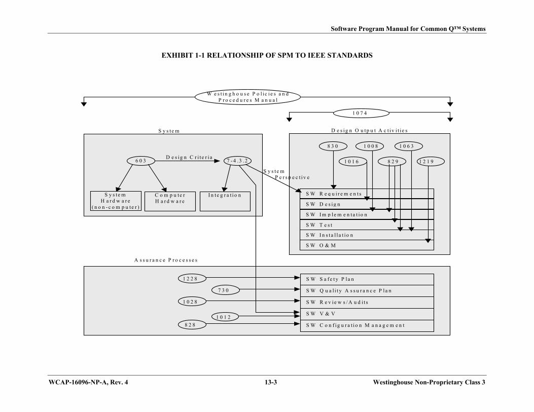
Software Program Manual for Common Q™ Systems
WCAP-16096-NP-A, Rev. 4 13-3 Westinghouse Non-Proprietary Class 3
EXHIBIT 1-1 RELATIONSHIP OF SPM TO IEEE STANDARDS
W e s t i n g h o u s e P o l i c i e s a n dP r o c e d u r e s M a n u a l
1 0 7 4
S W O & M
S W I n s t a l l a t io n
S W T e s t
S W I m p l e m e n ta t io n
S W D e s i g n
S W R e q u i r e m e n t s
1 0 0 8
8 2 9
8 3 0
D e s ig n O u t p u t A c t iv i t i e s
S y s te mH a r d w a r e
( n o n - c o m p u te r )
C o m p u te rH a r d w a r e
I n t e g r a t i o n
6 0 3 7 - 4 .3 .2D e s ig n C r i t e r i a
S y s t e m P e r s p e c t iv e
S y s te m
S W C o n f ig u r a t i o n M a n a g e m e n t
S W S a f e t y P l a n
S W V & V
8 2 8
1 0 2 8
1 0 1 2
A s s u r a n c e P r o c e s s e s
1 2 1 9
1 2 2 8
S W R e v i e w s / A u d i t s
S W Q u a l i t y A s s u r a n c e P l a n7 3 0
1 0 6 3
1 0 1 6

Software Program Manual for Common Q™ Systems
WCAP-16096-NP-A, Rev. 4 13-4 Westinghouse Non-Proprietary Class 3
EXHIBIT 2-1 DESIGN/IV&V TEAM ORGANIZATION
SeniorVP
I
I I
Engineering Quality
I I
Engineering VP
I
I I
Engineering Director IV & V Director
I I
Design Team ELM IV &V Team ELM (multiple groups)
---1 EPM I
I IV&V Team Leader
---1 Manufacturing Lead I
-IV & V Engineers
-
C Librarian -
Technicians
---1 Hardware Technical Lead I
C Hardware Engineers
---1 Software Technical Lead I
C Software Engineers

Software Program Manual for Common Q™ Systems
WCAP-16096-NP-A, Rev. 4 13-5 Westinghouse Non-Proprietary Class 3
EXHIBIT 4-1 ASSIGNMENT OF COMMON Q™ SOFTWARE TO CLASSES
SYSTEM SUB-SYSTEM SCOPE CLASS
Plant Protection/Reactor Protection Safety Critical Kernel (LCL, Bistable)
Maintenance and Test Panel (MTP)
Operator’s Module
Interface and Test Processor (ITP)
Intra-Divisional Communication Software (AF100)
All Other Software
Development Tools
Protection
Important-to-Safety
Important-to-Safety
Important-to-Safety
Important-to-Safety
General Purpose
General Purpose
Engineered Safety Features Actuation Safety Critical Kernel (ILP)
MTP
Intra-Divisional Communication Software (AF100)
All Other Software
Development Tools
Protection
Important-to-Safety
Important-to-Safety
General Purpose
General Purpose

Software Program Manual for Common Q™ Systems
WCAP-16096-NP-A, Rev. 4 13-6 Westinghouse Non-Proprietary Class 3
EXHIBIT 4-1 ASSIGNMENT OF COMMON Q™ SOFTWARE TO CLASSES (cont.)
SYSTEM SUB-SYSTEM SCOPE CLASS
Core Protection Calculator Safety Critical Kernel (FLOW, UPDATE, POWER, STATIC)
CEAC Software
MTP
Operators Module
Intra-Divisional Communication Software (AF100)
CEAPDS
All Other Software
Development Tools
Protection
Protection
Important-to-Safety
Important-to-Safety
Important-to-Safety
Important-to-Availability
General Purpose
General Purpose
Post Accident Monitoring Kernel Software (CET, SM, RVL monitoring)
Flat Panel Display System
Intra-Divisional Communication Software (AF100)
All Other Software
Development Tools
Important-to-Safety
Important-to-Safety
Important-to-Safety
General Purpose
General Purpose

Software Program Manual for Common Q™ Systems
WCAP-16096-NP-A, Rev. 4 13-7 Westinghouse Non-Proprietary Class 3
EXHIBIT 4-2 COMMON Q™ SOFTWARE DEVELOPMENT PROCESS
P,ojec1 Qual ity Ptan (EPM)
/ System Roqui' omeols
Sped1Icetlon (~Team)
R"'Iu;""m<H11s Input tORTM
(De-slgn Team)
L.
Des;go Inpol to
" " (o....Ign Team)
L.
IfJ1!lIeme<1taoo... Inpol to RTM
(De-slgn Team)
, ...
Module T ... I RepOO. "
(IV&-I/ Team)
Unit T8$t Reports"" (IV&'V T .... mj
Inl..",.oo... Tesl ,-(lV&.I/ Team)
FIICior)' Acceptan"" Tesl Report (lV&.I/ Team)
ion Cia .. SIW Only Pruloct
""-and Impo<Ii!nl to Safely C .... SlW Only
Coding Standard &-Guldel ......
WeslinghOlJse
~ -, V
,~, -. MlmUlOI
[][] 'w, ~,
, ...
-- Te st Pia" &-Roqu;""me'''$ Procedure. - - (IV&-I/ Team) (o-ign Team)
Sof\wa,e o.."q. T",IInpol 10 - "" (o....Ign Team) (11/&1/ Team)
SIW Implementalk>n Engin_ ng Testing son .... 'e Rei ....... '--(o-ign Team) l/eriOCalioo
(II/&.I/ TQ3mj
Modu le T8$ti ng" (IV&'V T .... mj
Unit Testing"" ( IV&'V T .... mj
Intogralk>n T8$ti ng (IV&.V T .... mj
FaCio<)' """"pIion"" T8$ting
(lV&.I/ Team)
FinaI IY&-Y Reportar1d Code Certificate
(lV&.I/ Team)

Software Program Manual for Common Q™ Systems
WCAP-16096-NP-A, Rev. 4 13-8 Westinghouse Non-Proprietary Class 3
EXHIBIT 4-3 TASKS REQUIRED FOR SOFTWARE CATEGORIES
TASK
ORIGINAL
SOFTWARE
ETBM
SOFTWARE
ENM
SOFTWARE
SQA PLANNING PHASE
SOFTWARE QUALITY ASSURANCE PLAN X X X
CODING STANDARDS X X
SOFTWARE VERIFICATION AND VALIDATION PLAN X X X
SOFTWARE CONFIGURATION MANAGEMENT PLAN X X X
SOFTWARE REQUIREMENTS PHASE
SYSTEM REQUIREMENTS X X X
PROTOTYPE CODING As Required
SOFTWARE REQUIREMENTS X X X
SOFTWARE DESIGN PHASE
SOFTWARE DESIGN DESCRIPTION X X
REQUIREMENTS TRACEABILITY ANALYSIS X X X
SOFTWARE IMPLEMENTATION PHASE
MODULE CODING X X
TEST PLAN X X X
MODULE TEST PROCEDURE (Protection) X X
MODULE TEST EXECUTION X X

Software Program Manual for Common Q™ Systems
WCAP-16096-NP-A, Rev. 4 13-9 Westinghouse Non-Proprietary Class 3
EXHIBIT 4-3 TASKS REQUIRED FOR SOFTWARE CATEGORIES (cont.)
TASK
ORIGINAL
SOFTWARE
ETBM
SOFTWARE
ENM
SOFTWARE
MODULE TEST EXECUTION REPORT (Protection) X X
UNIT TEST PROCEDURE (Protection and Important-to-Safety) X X X
UNIT TEST EXECUTION X X X
UNIT TEST REPORT (Protection and Important-to-Safety) X X X
REQUIREMENTS TRACEABILITY ANALYSIS X X
SOFTWARE TEST PHASE
INTEGRATION TEST PROCEDURE X X X
INTEGRATION TEST EXECUTION X X X
INTEGRATION TEST REPORT X X X
SYSTEM TEST (FAT) PROCEDURE X X X
SYSTEM TEST (FAT) EXECUTION X X X
SYSTEM TEST (FAT) REPORT X X X
USER DOCUMENTATION X X X
SOFTWARE IV&V REPORT X X X
SOFTWARE INSTALLATION & CHECKOUT PHASE
INSTALLATION TEST (SAT) PROCEDURE* X X X
INSTALLATION TEST (SAT) EXECUTION* X X X

Software Program Manual for Common Q™ Systems
WCAP-16096-NP-A, Rev. 4 13-10 Westinghouse Non-Proprietary Class 3
EXHIBIT 4-3 TASKS REQUIRED FOR SOFTWARE CATEGORIES (cont.)
TASK ORIGINAL
SOFTWARE
ETBM
SOFTWARE
ENM
SOFTWARE
INSTALLATION TEST (SAT) REPORT* X X X
SOFTWARE OPERATION AND MAINTENANCE PHASE
MAINTAIN SOFTWARE X X X
SOFTWARE RETIREMENT PHASE
RETIREMENT NOTIFICATION X X X
ETBM – Existing Software To Be Modified
ENM – Existing Software Not To Be Modified
*Applicable if within Westinghouse scope of supply.

Software Program Manual for Common Q™ Systems
WCAP-16096-NP-A, Rev. 4 13-11 Westinghouse Non-Proprietary Class 3
EXHIBIT 4-4 COMMON Q™ COMMENT RECORD
DOCUMENT
NUMBER/REVISION:
SECTION
REFERENCE COMMENT COMMENT RESOLUTION
Reviewed by: Name Signature Date

Software Program Manual for Common Q™ Systems
WCAP-16096-NP-A, Rev. 4 13-12 Westinghouse Non-Proprietary Class 3
EXHIBIT 5-1 SOFTWARE TASKS AND RESPONSIBILITIES
TASK PROTECTION
IMPORTANT-
TO-SAFETY
IMPORTANT-
TO-
AVAILABILITY
GENERAL
PURPOSE
SOFTWARE REQUIREMENTS PHASE
SYSTEM AND SOFTWARE REQUIREMENTS DT/VT DT/VT DT DT
REQUIREMENTS VERIFICATION VT VT*** N/A N/A
SOFTWARE DESIGN PHASE
SOFTWARE DESIGN DESCRIPTION DT/VT DT/VT DT DT
PROTOTYPE CODING DT DT DT DT
DESIGN VERIFICATION VT VT*** N/A N/A
SOFTWARE IMPLEMENTATION PHASE
TEST PLAN (MAY BE PART OF SVVP) VT VT DT DT
MODULE CODING DT/VT DT/VT DT DT
MODULE TEST PROCEDURE** VT N/A N/A N/A
MODULE TEST EXECUTION/REPORT** VT N/A N/A N/A
UNIT TEST PROCEDURE VT VT N/A N/A
UNIT TEST EXECUTION/REPORT VT VT N/A N/A
IMPLEMENTATION VERIFICATION VT VT*** DT DT
SOFTWARE TEST PHASE
INTEGRATION TEST PROCEDURE VT VT DT DT

Software Program Manual for Common Q™ Systems
WCAP-16096-NP-A, Rev. 4 13-13 Westinghouse Non-Proprietary Class 3
EXHIBIT 5-1 SOFTWARE TASKS AND RESPONSIBILITIES (cont.)
TASK PROTECTION IMPORTANT-
TO-SAFETY
IMPORTANT-
TO-
AVAILABILITY
GENERAL
PURPOSE
INTEGRATION TEST EXECUTION VT VT DT DT
INTEGRATION TEST REPORT VT VT DT DT
SYSTEM TEST (FAT) PROCEDURE VT VT DT DT
SYSTEM TEST (FAT) EXECUTION VT VT DT DT
SYSTEM TEST (FAT) REPORT VT VT DT DT
USER DOCUMENTATION DT/VT DT/VT DT DT
SOFTWARE IV&V REPORT VT VT N/A N/A
SOFTWARE INSTALLATION & CHECKOUT PHASE
INSTALLATION TEST (SAT) PROCEDURE* VT VT DT DT
INSTALLATION TEST (SAT) EXECUTION* VT VT DT DT
INSTALLATION TEST (SAT) REPORT* VT VT DT DT
KEY: ACTIVITY PERFORMED BY/REQUIRES IV&V
(i.e., DT/VT means DT performs activity and requires IV&V,
DT means DT performs activity but does not require IV&V,
VT means activity performed by IV&V, and N/A means
activity is not required)
DT = DESIGN TEAM VT = IV&V TEAM
*Applicable if in Westinghouse scope of supply.
** These activities are performed for Protection Class software only.
*** Same IV&V activities as Protection Class software except for Software Hazards Analysis described in subsection 3.4.1.

Software Program Manual for Common Q™ Systems
WCAP-16096-NP-A, Rev. 4 13-14 Westinghouse Non-Proprietary Class 3
EXHIBIT 5-2 CHECKLIST NO. 1, SOFTWARE VERIFICATION AND VALIDATION
CONCEPT PHASE CHECKLIST
Software Item Name: Software Item ID:
1. Were the following IV&V tasks completed during the Concept Phase?: YES
a. Review Concept documents for consistency, incompatibilities, and compliance to
regulations.
b. Identify major constraints of interfacing systems.
c. Identify constraints or limitations of proposed system.
d. Assess allocation of functions to hardware and software items.
e. Assess criticality of each software item.
f. Configuration management evaluation of all applicable conceptual documents (including evaluating if conceptual documents have been captured properly and placed under configuration control).
g. Verify tracing of project baseline documents for compliance to customer requirements, applicable product documents and regulatory standards and guidelines.
h. Complete EXHIBIT 5-2 CHECKLIST NO. 1, SOFTWARE VERIFICATION AND VALIDATION CONCEPT PHASE CHECKLIST and reference completed checklist in the Concept Phase IV&V Report.
Reviewer’s comments (Optional):

Software Program Manual for Common Q™ Systems
WCAP-16096-NP-A, Rev. 4 13-15 Westinghouse Non-Proprietary Class 3
Reviewed by: Name Signature Date

Software Program Manual for Common Q™ Systems
WCAP-16096-NP-A, Rev. 4 13-16 Westinghouse Non-Proprietary Class 3
EXHIBIT 5-3 CHECKLIST NO. 2, SOFTWARE VERIFICATION AND VALIDATION
REQUIREMENTS PHASE CHECKLIST
Software Item Name: Software Item ID:
1. Were the following IV&V tasks completed during the Requirements Phase?: YES
a. Review the adequacy and accuracy of the RTM as prepared by the design team. The
review shall include verification that all functional, hardware interface, software,
performance, and user requirements have been included.
b. Perform or review the adequacy and accuracy of the following software safety
analyses using Reference 26, Annex A.1 as criteria:
1. Criticality
2. Specification
3. Timing and Sizing
4. Different software systems (if applicable)
c. Review applicable Commercial Grade Dedication reports to evaluate the suitability
of the commercially dedicated item for the particular implementation being
verified. Commercial Grade Dedication Report characteristics are defined in
subsection 5.5.3.2, item 7.
d. Verify identification of the original software items developed under this SPM for
generic application that will be used in the project; verify that the qualification
status has been identified and is appropriate; and verify through the RTA process
that this software meets the requirements.
e. Develop a Common Q™ specific test plan in accordance with the content, not the format of Reference 14, Section 4. Verify that it includes the following topics as a minimum:
1. General approach including: identification of test procedures, general test
methods, documentation of results, and traceability methods to the SRS and
SDD.
2. Requirements for testing including: test boundary conditions on inputs and
unexpected input conditions.

Software Program Manual for Common Q™ Systems
WCAP-16096-NP-A, Rev. 4 13-17 Westinghouse Non-Proprietary Class 3
3. Test management including: personnel, resources, organization, and
responsibilities.
4. Procedures for qualification and control of the hardware to be used in
testing.
5. Qualification and use of software tools.
6. Installation test requirements for existing software that is used without
modification.
7. Regression test requirements for previously qualified software to be
modified.
8. Delineate major features of the system that will be tested.
f. Configuration Management Evaluation – assess the applicability of the Software
Configuration Management Plan (Section 6) to the project as augmented by the
project plan.
g. A review shall be conducted to verify that each hazard identified in the software
hazard analysis and/or failure modes and effects analysis, has been mitigated or the
risks associated with the hazard have been reduced to an acceptable level.
h. Complete EXHIBIT 5-3 CHECKLIST NO. 2, SOFTWARE VERIFICATION
AND VALIDATION REQUIREMENTS PHASE CHECKLIST and reference
completed checklist in the Requirements Phase IV&V Report.
2. Does the review of available documentation identify: YES
a. Completeness and correctness in specifying the performance requirements and
operational capabilities and concepts of the system. Does the system design
implement the functional requirements, are the plant parameters defined in the
functional design being monitored in the system design?
b. Completeness and correctness in system definition and interfaces with other
equipment. Perform analysis of requirements decomposition – are subsystems defined
with interface requirements noted?
c. Unambiguous, correct, and consistent description of the interfaces and performance
characteristics of each major function.
d. Establishment of a reasonable and achievable set of test requirements. These
requirements should be related to performance goals and also define acceptability

Software Program Manual for Common Q™ Systems
WCAP-16096-NP-A, Rev. 4 13-18 Westinghouse Non-Proprietary Class 3
criteria.
e. Definition of physical characteristics, reliability and maintainability objectives,
operating environment, transportability constraints, design and documentation
standards.
f. Definition of the necessary training requirements and considerations.
g. Treatment of man/machine interface requirements. ____
h. Definition of integration requirements. ____
i. Definition of installation, operation, and maintenance requirements. ____
j. Are the bases for the requirements identified? ____
k. Review requirements with respect to the following possible errors:
1. Inadequate or partially missing performance criteria.
2. Inadequate or partially missing operating rules (or information).
3. Inadequate or partially missing ambient environment information.
4. Requirements that are incompatible with other requirements.
5. Inadequate or partially missing system mission information.
6. Ambiguous or requirements subject to misinterpretation. 7. User's needs not properly understood or reflected.
8. Requirement not traceable to user's needs.
9. Requirements which cannot be physically tested.
10. Accuracy specified does not conform to the need.
11. Data environment inadequately described.
12. Input/output data parameters units incorrect.
13. Erroneous external interface definition.
14. Initialization of the system not properly considered.
15. Vague requirements of the functions to be performed.
16. Required processing inaccurate.
17. Required processing inefficient.
18. Required processing not necessary.
19. Missing requirements on flexibility, maintainability.
20. Missing or incomplete requirements of response to abnormal data or events.
21. Inadequate or incorrect algorithm.
22. Incorrect timing/synchronization requirements.
____

Software Program Manual for Common Q™ Systems
WCAP-16096-NP-A, Rev. 4 13-19 Westinghouse Non-Proprietary Class 3
23. Incorrect hardware interface requirements.
24. Incorrect allocation of system resources.
l. Has the document author updated the RTM? Is the RTM adequate and accurate in
providing the traceability of requirements?
____
3. Do the hardware interface requirements identify: YES
a. All input/output and requirements, including range, accuracies and data rates.
b. Design features (e.g., keylocks) which provide administrative control of all devices
capable of changing the content of the stored programs or data.
____
c. Initialization requirements, such as power-up and power-down.
d. Design features for the detection of system failures (e.g., on-line self-tests).
e. Manually-initiated in-service test or diagnostic capabilities.
f. Human factors engineering design features that ease the interaction with the system
for operation, maintenance, and testing.
g. Margins for timing, memory/buffer size, etc., including minimum margins for design.
h. Interrupt features.
4. Do the software requirements identify: YES
a. Process inputs including voltage and sampling frequency.
b. System software, utility routines and other auxiliary programs required for operation
c. Algorithms to be programmed with consideration to handling of abnormal events
d. Data files and data required for the algorithms, including symbolic names and
requirements for flexibility.
e. Process outputs, including ranges, accuracies, update interval, and human factors
considerations of the operator interface.

Software Program Manual for Common Q™ Systems
WCAP-16096-NP-A, Rev. 4 13-20 Westinghouse Non-Proprietary Class 3
f. Initialization requirements, such as initial values and start-up sequence.
g. Parameters to configure system program logic for response to detected failures.
h. Operator interface requirements (switches, readouts).
i. In-service test or diagnostic capabilities.
j. Timing requirements for all time-dependent events, including overall system
requirements.
k. Limitations on processor time and memory capabilities.
l. Security requirements (e.g., passwords).
Reviewer’s comments (Optional):
Reviewed by: Name Signature Date

Software Program Manual for Common Q™ Systems
WCAP-16096-NP-A, Rev. 4 13-21 Westinghouse Non-Proprietary Class 3
EXHIBIT 5-4 CHECKLIST NO. 3, SOFTWARE VERIFICATION AND VALIDATION DESIGN
PHASE CHECKLIST
Software Item Name: Software Item ID:
1. Were the following IV&V tasks completed during the Design Phase?: YES
a. Review system design documentation to verify the system design completely and
correctly performs the functions specified in the requirements documents.
b. Review system design documentation to determine that the hardware/software
interface design specifications are understandable, unambiguous, reasonable,
implementable, accurate, complete, and are a faithful translation of the
hardware/software interface design requirements into hardware/software interface
design specifications
c. Review software design documentation to verify design requirements are
adequately incorporated. The design documentation shall address all software
requirements and provide a correlation of the design elements with the software
requirements.
d. Perform or review the adequacy and accuracy of the following software safety
design analyses using Reference 26, Annex A.2 as criteria:
a. Logic
b. Data
c. Interface
d. Constraint
e. Functional
f. Software element
e. Review current criticality analysis assessment for continued applicability.
f. Perform the Requirements Traceability Analysis.
g. Configuration Management – Confirm that the verified design documents have

Software Program Manual for Common Q™ Systems
WCAP-16096-NP-A, Rev. 4 13-22 Westinghouse Non-Proprietary Class 3
been properly placed under configuration control.
h. Begin preparing module, unit, integration, and FAT test procedures in accordance
with Reference 14, Section 7.
i. Review the software hazard analysis and/or failure modes and effects analysis to
verify that any new hazards have been documented during this phase.
j. Complete EXHIBIT 5-4 CHECKLIST NO. 3, SOFTWARE VERIFICATION
AND VALIDATION DESIGN PHASE CHECKLIST and reference in the Design
Phase IV&V Report.
2. Does the available documentation adequately address: YES
a. Architecture, for both hardware and software.
b. Input/output interface.
c. System and Executive Control.
d. Operating Sequences – initialization, start-up, error detection, restart, etc.
e. Testability – use of test equipment, such as data tapes, simulations, etc.
f. Timing analysis – sampling rates, response time, etc.
g. Availability – what does analysis and data indicate?
h. Algorithm design and data verification.
i. Information flow – communication between subsystems, data management and signal
conversion to engineering units.
j. Human factors engineering.
k. Is the design correct, complete, and traceable to requirements? Has the document
author updated the RTM? Is the RTM adequate and accurate in providing the
traceability of software design descriptions to requirements?

Software Program Manual for Common Q™ Systems
WCAP-16096-NP-A, Rev. 4 13-23 Westinghouse Non-Proprietary Class 3
l. Is the design internally consistent?
m. Is the design feasible?
n. Is the design clear and unambiguous?
o. Is the design testable?
p. Software design as a whole emphasizing allocation of software components to
function, functional flows, storage requirements and allocations, and design of the
database.
q. General description of the size and operating characteristics of all support software.
Reviewer’s comments (Optional):
Reviewed by: Name Signature Date

Software Program Manual for Common Q™ Systems
WCAP-16096-NP-A, Rev. 4 13-24 Westinghouse Non-Proprietary Class 3
EXHIBIT 5-5 CHECKLIST NO. 4, SOFTWARE VERIFICATION AND VALIDATION
IMPLEMENTATION PHASE CHECKLIST
Software Item Name: Software Item ID:
1. Were the following IV&V tasks completed during the Implementation Phase?: YES
a. Review the as-built software documentation to verify the as-built software
completely and correctly implements the design specified in the system design
documents.
b. Perform or review the adequacy and accuracy of following software safety code
analyses using Reference 26, Annex A.3 as criteria:
1. Logic
2. Data
3. Interface
4. Constraint
5. Programming Style
6. Non-critical code
7. Timing and sizing
c. Review current criticality analysis assessment for continued applicability.
d. Perform the Requirements Traceability Analysis.
e. Evaluate Software Configuration Management activities and verify the
requirements of Section 6 are fulfilled.
f. Hardware implementation review is normally conducted as part of the hardware
quality assurance activities defined elsewhere
g. For Protection Class software, review software testing records to verify adequate
structural testing.
h. System test procedures are prepared in accordance with Reference 14, Section 7,
based upon the requirements of the design and shall include test cases

Software Program Manual for Common Q™ Systems
WCAP-16096-NP-A, Rev. 4 13-25 Westinghouse Non-Proprietary Class 3
encompassing the range of usage intended for the system. Test Procedure shall
include the characteristics listed in subsection 5.5.5.2, item 11.
i. Review the software hazard analysis and/or failure modes and effects analysis to
verify that any new hazards have been documented during this phase.
j. Complete EXHIBIT 5-5 CHECKLIST NO. 4, SOFTWARE VERIFICATION
AND VALIDATION IMPLEMENTATION PHASE CHECKLIST and reference
completed checklist in the Implementation Phase IV&V Report.
2. Review the source code with respect to the following: YES
a. Does the source code conform to specified standards and procedures including
Reference 31 and coding standards and guidelines?
b. Are the comment statements sufficient to give an adequate description of each
routine?
c. Is the source code clearly understandable?
d. Is the source code logically consistent with design specs? Has the programmer
updated the RTM? Is the RTM adequate and accurate in providing the traceability of
software modules to software design descriptions?
e. Are all variables properly specified and used?
f. Is there satisfactory error checking?
g. Do all subroutine calls transfer variables correctly?
h. Is the data read in each file consistent with the data written to it?
3. Do the database modules adequately and correctly reflect: YES
a. Program and general content.
b. File organization, layout, and residence.
c. File accessing methods.

Software Program Manual for Common Q™ Systems
WCAP-16096-NP-A, Rev. 4 13-26 Westinghouse Non-Proprietary Class 3
d. File size.
e. Data record description(s) – record layout, field allocations, field names, detailed
description of field contents.
f. Initialization requirements.
g. Data accuracy. (See subsection 5.4.5.4.)
h. Data completeness. (See subsection 5.4.5.4.)
i. Maintenance.
4. Review Module Test Documentation YES
a. Has module testing been documented for all protection class software?
b. Is the test coverage documented?
c. Is the test coverage adequate? Verify that all branches of all software modules have
been tested or that adequate justification and analysis has been completed for untested
branches.
d. Do module test reports indicate correct execution of critical software elements?
5. Review Unit Test Documentation YES
a. Has unit testing been documented for all protection and important-to-safety class
software?
b. Is the test coverage documented?
c. Is the test coverage adequate? Verify that all functions of all software units have
been tested or that adequate justification and analysis has been completed for untested
functions.
d. Do unit test reports indicate correct execution of critical software functions?
6. Do procedures exist (as necessary) to: YES

Software Program Manual for Common Q™ Systems
WCAP-16096-NP-A, Rev. 4 13-27 Westinghouse Non-Proprietary Class 3
a. Generate all object code required for system generation and produce the
corresponding software listings.
b. Generate a customized database and system parameter file according to plant-specific
requirements and produce the corresponding listings.
c. Configure the operating system according to the plant-specific hardware
configuration.
d. Generate the system from the above results.
e. Initialize and boot the system after system generation.
f. Modify, enhance, and maintain the system including the usage of diagnostic and
debugging utilities.
g. Generate and update displays.
h. Integrate the hardware/configured software.
Reviewer’s comments (Optional):
Reviewed by: Name Signature Date

Software Program Manual for Common Q™ Systems
WCAP-16096-NP-A, Rev. 4 13-28 Westinghouse Non-Proprietary Class 3
EXHIBIT 5-6 CHECKLIST NO. 5, SOFTWARE VERIFICATION AND VALIDATION TEST
PHASE CHECKLIST
Software Item Name: Software Item ID:
1. Were the following IV&V tasks completed during the Test Phase?: YES
a. Follow up on changes and corrections made in the system in accordance with
change control procedures in Section 6.
b. Perform the Requirements Traceability Analysis.
c. Review user documentation. This may be done as part of the Installation and
Checkout phase if within Westinghouse’s scope of supply by specific contract.
d. Perform Functional Review to verify that all requirements specified in the SRS
have been met. This review shall include an overview of all documentation and a
review of the results of the previous reviews, including Software Requirements
Review, ADR, CDR, and if applicable, interim IV&V reports (for Protection and
Important-to-Safety class software). The tasks conducted in this phase meet the
requirements of subsection 4.6.2.5, Functional Review.
e. Complete EXHIBIT 5-6 CHECKLIST NO. 5, SOFTWARE VERIFICATION
AND VALIDATION TEST PHASE CHECKLIST and reference completed
checklist in the Installation and Checkout Phase IV&V Report.
f. At the completion of all other tasks in this phase, a final IV&V report is issued. The
final IV&V report may not be issued until the Installation and Checkout Phase if
within Westinghouse’s scope of supply by specific contract. Final IV&V report
characteristics are defined in subsection 5.5.7.2, item 4.
2. Verify program integration with hardware in accordance with the following: YES
a. Does the integrated program conform to the maximum resource requirements for
memory size and program execution time?

Software Program Manual for Common Q™ Systems
WCAP-16096-NP-A, Rev. 4 13-29 Westinghouse Non-Proprietary Class 3
b. Does the integrated program interface properly with external files?
c. Have all of the elements of the integrated program been identified in the module list?
d. Does the code compile and link without errors?
e. Are interfaces between programs, data files, and libraries correctly programmed?
3. Verify program validation in accordance with the following: YES
a. Has the test engineer updated the RTM? Is the RTM adequate and accurate in
providing the traceability of software test cases to software modules and
requirements?
b. Has each section of the test procedure been completed accurately?
c. Have all tests passed and have all requirements of testing been fulfilled?
d. Have applicable software hazard prevention and/or control features been tested?
4. Verify test results and report in accordance with the following: YES
a. Does the Test Report comply with the format specified in the Test Plan?
– Does it provide complete identification of the program tested?
– Does it specify the scope of the Test Report?
– Does it reference the Test Plan and any other relevant documents?
– Does it include a complete and accurate description of the test environment:
Hardware configuration?
Support software used?
– Does it describe and justify each deviation from the Test Plan?
– Does it provide a summary of test results?

Software Program Manual for Common Q™ Systems
WCAP-16096-NP-A, Rev. 4 13-30 Westinghouse Non-Proprietary Class 3
– Does it include an evaluation of the program performance with respect to
requirements?
– Does it provide recommendations for retesting, or program acceptance, or both?
– Does it provide a detailed description of the results of each test case?
– Does it include a copy of the test case log?
– Does it include all discrepancy reports prepared during the testing?
b. Is the information in the Test Report an accurate statement of the testing performed?
– Does the output summary of test results accurately reflect the test output
produced?
– Is the evaluation of the program a realistic and accurate reflection of the test
results?
– Are the recommendations regarding retesting and acceptance sound and based on the test results?
– Do the descriptions of the test case results accurately reflect actual test outputs?
– Is the test case log complete and consistent with actual test output?
– Are the discrepancy reports complete and consistent with actual test output?
c. Have all test cases been executed correctly?
– Does the test case log indicate performance of each test case in the specified test environment using specified test procedures?
– Is there an explanation for any deviation from the specified test environment or procedures?
– Is there an Exception Report for each deviation from expected results?
– Were correct input data used for each test case?

Software Program Manual for Common Q™ Systems
WCAP-16096-NP-A, Rev. 4 13-31 Westinghouse Non-Proprietary Class 3
– Is the output produced by each test case accurately reported?
5. General Assessment Questions: YES
a. Is there convincing evidence that the system meets protection system safety requirements?
b. Is there convincing evidence that the system does not introduce any new hazards?
Reviewer’s comments (Optional):
Reviewed by: Name Signature Date

Software Program Manual for Common Q™ Systems
WCAP-16096-NP-A, Rev. 4 13-32 Westinghouse Non-Proprietary Class 3
EXHIBIT 5-7 CHECKLIST NO. 6, SOFTWARE VERIFICATION AND VALIDATION
INSTALLATION AND CHECKOUT PHASE CHECKLIST
Software Item Name: Software Item ID:
1. Were the following IV&V tasks completed during the Installation and Checkout Phase?: YES
a. Review installation procedures and user manuals to verify that they are complete
and correct.
b. Review training materials (if within Westinghouse’s scope of supply) for the
following:
1. Safety training for the users, operators, maintenance and management
personnel
2. System startup training
3. Safety training requirements are met
c. Review that the Exception Report Log that was maintained in accordance with the
SAT plan.
d. Perform the Requirements Traceability Analysis.
e. Configuration Management - Evaluate that the manuals and procedures have been
properly placed under configuration control.
f. Complete EXHIBIT 5-7 CHECKLIST NO. 6, SOFTWARE VERIFICATION
AND VALIDATION INSTALLATION AND CHECKOUT PHASE CHECKLIST
and reference completed checklist in Final IV&V report.
g. At the completion of all others tasks in this phase, prepare and issue the final IV&V
report. This report will be issued during the Test Phase if the Installation and
Checkout Phase are not within Westinghouse’s scope of supply.
2. Is the user documentation installation package sufficient to install the software on the delivered hardware?
3. Is the user documentation clear, unambiguous, and consistent with system requirements?

Software Program Manual for Common Q™ Systems
WCAP-16096-NP-A, Rev. 4 13-33 Westinghouse Non-Proprietary Class 3
4. Does the IV&V report have positive findings?
5. Have all discrepancies and IV&V findings been resolved to the satisfaction of the IV&V team?
6. Are SCM controls in place for the user to report errors?
7. Training documentation meet Safety Training Requirements
8. Is the software installed correctly?
9. Have configuration tables been correctly initialized, if such are used?
10. Are operating documents present, correct, complete, and consistent?
Reviewer’s comments (Optional):
Reviewed by: Name Signature Date

Software Program Manual for Common Q™ Systems
WCAP-16096-NP-A, Rev. 4 13-34 Westinghouse Non-Proprietary Class 3
EXHIBIT 5-8 IEEE STANDARD 1012-1998 COMPLIANCE TABLE
a,c

Software Program Manual for Common Q™ Systems
WCAP-16096-NP-A, Rev. 4 13-35 Westinghouse Non-Proprietary Class 3
a,c

Software Program Manual for Common Q™ Systems
WCAP-16096-NP-A, Rev. 4 13-36 Westinghouse Non-Proprietary Class 3
a,c

Software Program Manual for Common Q™ Systems
WCAP-16096-NP-A, Rev. 4 13-37 Westinghouse Non-Proprietary Class 3
a,c

Software Program Manual for Common Q™ Systems
WCAP-16096-NP-A, Rev. 4 13-38 Westinghouse Non-Proprietary Class 3
a,c
Software Program Manual for Common Q™ Systems
WCAP-16096-NP-A, Rev. 4 13-39 Westinghouse Non-Proprietary Class 3
a,c

Software Program Manual for Common Q™ Systems
WCAP-16096-NP-A, Rev. 4 13-40 Westinghouse Non-Proprietary Class 3
a,c

Software Program Manual for Common Q™ Systems
WCAP-16096-NP-A, Rev. 4 13-41 Westinghouse Non-Proprietary Class 3
a c

Software Program Manual for Common Q™ Systems
WCAP-16096-NP-A, Rev. 4 13-42 Westinghouse Non-Proprietary Class 3
EXHIBIT 6-1 SOFTWARE CHANGE REQUEST FORM
SCR # _____
Date: ______ CUSTOMER: ____________________ Page 1 of ___
Subject: _____________________ Software Affected:________________
Originator: ___________________ Version: ______ Revision: ______
Classification[ ]: 1-Emergency 2-Corrective 3-Adaptive 4-Perfective
Summary of Requested Change:
Reason for Change:
Documents Affected (Document No./Revision):
_____________________________________
Design Approval/Date:
______________________________________
Engineering Project Manager/Date
Implementation Completed:
(Including Documentation)
___________________________________
Implementation Engineer/Date
Testing Completed:
Exception Report #: ______________________
Documentation: _______________________
Review/Date: ________________________

Software Program Manual for Common Q™ Systems
WCAP-16096-NP-A, Rev. 4 13-43 Westinghouse Non-Proprietary Class 3
EXHIBIT 10-1 COMPUTER CODE CERTIFICATE
The following computer code, as noted by its name, version number and executable file identification, is
approved for design use.
System Name:
Code Name:
Version/Revision Number:
Executable File Identification: _________________________________________________
Computer(s):
Restrictions (List any limitations on use, special hardware considerations, etc.):
Listed are the software modules and their current revision (use additional pages as necessary):
Module Name/Classification Version/Revision
Verification and Validation Report Number:
IV&V Team Leader: Date:

Software Program Manual for Common Q™ Systems
WCAP-16096-NP-A, Rev. 4 13-44 Westinghouse Non-Proprietary Class 3
EXHIBIT 11-1 EXCEPTION REPORT
Exception Report Number __________________
System Name: Plant:
Procedure Name: Procedure Number:
Tester Name: Rev.:
Summary of Exception: Date:
Class: Step:
Resolution:
Responsibility:
Implementation:
Procedure Correction Software Change
Implemented By: Date:
Retested By: Date:
Reviewed By: Date:

Software Program Manual for Common Q™ Systems
WCAP-16096-NP-A, Rev. 4 13-45 Westinghouse Non-Proprietary Class 3
EXHIBIT 11-2 CORRECTIVE ACTIONS PROCESS
(Last Page of Section 13)
... Step 1: Identification of Issue - (required information)
Or9'lnilaboo level 2:Engineering & Products Or9'lnilaboo level 3:New Plant Safety Systems
fooctiooat "~~.~;.~' '"~.~
Yes r No
r Supplier r Intemal QA Employee
Customer
Yes No
r Regulatory' Ag en cy r Trending
~aooediss"" re""ution:
Step 2: Identification of Issue - (optional information)
1$' ....... 1Ied SicJl!jlic!!oce I evetIr High
r Medium
r FixlTrend
Recom"""""'" Re""ution:? ~ SUWested Issue 0W0er:' j.:J
S"II9"sted ReSJ>OOsi~e 0r\I:' ~ Backllroond:' ~
Date Issue first Occurred:' ~ AffectedCustomerls~' ~
Affected Unitls~' ~ Affected S<wierls):' ~
Impacted Doc ...... ems, System? ~ Compooem, etc"
SUbmined 00 behalf ot.' ~ Isttiun flAAC;ssue"!lr Yes r. No
o;sposibooof Material:r Accept as is r Repair
Step J: Comments
Step 4: Prepare for Issue Review Meeting
Step 5: Event Codes
Step 6: Cause Analysis Summary
Step 8: Justification for Closure
IR Closure Checklist
Step 10: Workflow Information
r Suggestion for ImprOlie ment
r Operational EXjl erience
r Rewor1< r Scrap
Issue DescRptioo