Embed Size (px)
Citation preview
Software Process Engineering Management
The Software Process Engineering Metamodel (SPEM)
Second Revised Submission OMG document number: ad/2001-06-05 June 6th, 2001 Submitted by IBM Rational Software Fujitsu/DMR SOFTEAM Unisys Alcatel Q-Labs Supported by Valtech Toshiba Siemens Computer Associates Adaptive Ltd. Nihon Unisys Ltd.
SPEM – ad/2001-06-05 1/78 rev 2.1c 6/6/2001
Copyright 2001 by International Business Machines Corporation Copyright 2001 by Rational Software Corporation Copyright 2001 by DMR Consulting Copyright 2001 by Fujitsu Limited Copyright 2001 by SOFTEAM Copyright 2001 by Unisys Corporation Copyright 2001 by Alcatel Copyright 2001 by Q-Labs The companies listed above hereby grant a royalty-free licence to the Object Management Group, Inc. (OMG) for worldwide distribution of this document or any derivative works thereof within OMG and to OMG members for evaluation purposes, so long as the OMG reproduces the copyright notices and the following paragraphs on all distributed copies. The material in this document is submitted to the OMG for evaluation. Submission of this document does not represent a commitment to implement any portion of this specification in the products of the submitters. WHILE THE INFORMATION IN THIS DOCUMENT IS BELIEVED TO BE ACCURATE, THE COMPANIES LISTED ABOVE MAKE NO WARRANTY OF ANY KIND WITH REGARD TO THIS MATERIAL INCLUDING BUT NOT LIMITED TO THE IMPLIED WARRANTIES OF MERCHANTABILITY AND FITNESS FOR A PARTICULAR PURPOSE. The companies listed above shall not be liable for errors contained herein or for incidental or consequential damages in connection with the furnishing, performance or use of this material. The information contained in this document is subject to change without notice. This document contains information, which is protected by copyright. All Rights Reserved. Except as otherwise provided herein, no part of this work may be reproduced or used in any form or by any means—graphic, electronic or mechanical, including photocopying, recording, taping, or information storage and retrieval systems—without the permission of one of the copyright owners. All copies of this document must include the copyright and other information contained on this page. The copyright owners grant member companies of the OMG permission to make a limited number of copies of this document (up to 50 copies) for their internal use as part of the OMG evaluation process. RESTRICTED RIGHTS LEGEND. Use, duplication, or disclosure by government is subject to restrictions as set forth in subdivision (c) (1) (ii) of the Right in Technical Data and Computer Software Clause at DFARS 252.227.7013. CORBA, Object Request Broker, UML, Unified Modeling Language, and OMG are trademarks of Object Management Group. RUP, Rational Unified Process, Rational Process Workbench are registered trademarks of Rational Software. DMR Macroscope is a trademark of DMR. Revision 2.1 c
Spem in alium numquam habui. (I have never placed my hope in any other.) Motet in 40 parts, Thomas Tallis (c.1505-1585)
SPEM – ad/2001-06-05 2/78 rev 2.1c 6/6/2001
Table of Contents 1 Introduction...............................................................................................................6
1.1 Overview ......................................................................................................................6 1.2 Modeling Approach ....................................................................................................6 1.3 Scope.............................................................................................................................7 1.4 Terminology.................................................................................................................7 1.5 Relationships to Other OMG Specifications.............................................................8
UML ....................................................................................................................................................8 UML Profile.........................................................................................................................................8 MOF 1.3 and XMI ...............................................................................................................................9 Workflow...........................................................................................................................................10 Proof of Concept................................................................................................................................10
1.6 Compliance points.....................................................................................................11 Examples............................................................................................................................................12
2 Mapping to RFP Requirements..............................................................................13 2.1 Mandatory Requirements: .......................................................................................13
Four-layer Architecture......................................................................................................................13 Relationship to UML and MOF.........................................................................................................13 XMI DTD ..........................................................................................................................................13 Basic Concepts...................................................................................................................................13 Process Examples ..............................................................................................................................14 Process Patterns and/or Components .................................................................................................14 Glossary .............................................................................................................................................14 Support for UML ...............................................................................................................................14 Categories ..........................................................................................................................................14 Natural Language Translation............................................................................................................15 Graphical Notation.............................................................................................................................15
2.2 Optional Requirements.............................................................................................15 Submission as a UML Profile ............................................................................................................15 Definition of Process Patterns and/or Components ...........................................................................16 Reification of UML Profile Concept .................................................................................................16
3 SPEM Foundation ..................................................................................................17 3.1 SPEM_Foundation::Data_Types.............................................................................17 3.2 SPEM_Foundation::Core.........................................................................................18 3.3 SPEM_Foundation::Model_Management..............................................................21 3.4 SPEM_Foundation Well-Formedness Rules ..........................................................22
4 Conceptual Model ...................................................................................................23 5 Package Structure ...................................................................................................24 6 Basic Elements ........................................................................................................25
6.1 ExternalDescription ..................................................................................................25
SPEM – ad/2001-06-05 3/78 rev 2.1c 6/6/2001
6.2 Guidance ....................................................................................................................25 Kinds of Guidance .............................................................................................................................26
7 Dependencies...........................................................................................................28 7.1 SPEM Dependencies .................................................................................................28 7.2 Well-formedness rules ..............................................................................................30
8 Process Structure ....................................................................................................31 8.1 WorkProduct and InformationElement .................................................................31
Associations .......................................................................................................................................31 Attributes ...........................................................................................................................................32 Note....................................................................................................................................................32 Examples............................................................................................................................................32 Synonyms...........................................................................................................................................32
8.2 WorkDefinition and ActivityParameter .................................................................32 Associations .......................................................................................................................................32 Attributes ...........................................................................................................................................33 Note....................................................................................................................................................33 Example .............................................................................................................................................33
8.3 Activity and Step .......................................................................................................33 Associations .......................................................................................................................................33 Examples............................................................................................................................................34 Synonyms...........................................................................................................................................34
8.4 ProcessPerformer and ProcessRole.........................................................................34 Associations .......................................................................................................................................34 Synonyms...........................................................................................................................................34 Examples............................................................................................................................................35 Notes ..................................................................................................................................................35
8.5 Well-formedness rules ..............................................................................................35 9 Process Components ...............................................................................................37
9.1 Package ......................................................................................................................37 9.2 ProcessComponent....................................................................................................37
Example .............................................................................................................................................37 9.3 Process........................................................................................................................38 9.4 Discipline....................................................................................................................39
Example .............................................................................................................................................39 Synonyms...........................................................................................................................................39
9.5 Well-formedness rules ..............................................................................................39 10 Process Lifecycle .................................................................................................41
10.1 Phase...........................................................................................................................41 Examples............................................................................................................................................42
10.2 Lifecycle .....................................................................................................................42 Associations .......................................................................................................................................42 Example .............................................................................................................................................42
10.3 Iteration .....................................................................................................................42 Example .............................................................................................................................................42
SPEM – ad/2001-06-05 4/78 rev 2.1c 6/6/2001
10.4 Precondition and Goal ..............................................................................................43 Example .............................................................................................................................................44
10.5 Well-formedness rules ..............................................................................................44 11 Management of Process Assets ..........................................................................45 12 SPEM as a UML Profile.....................................................................................46
12.1 Identified subset of the UML Metamodel ...............................................................47 Notes : ................................................................................................................................................49
12.2 Mapping to UML base classes..................................................................................49 12.3 Attributes ...................................................................................................................50 12.4 Associations ...............................................................................................................51 12.5 Use of Activity diagrams and Use Case diagrams..................................................52 12.6 Use of State diagrams ...............................................................................................53 12.7 Stereotypes of the SPEM profile..............................................................................53 12.8 Well-formedness rules ..............................................................................................54
Restricted multiplicities .....................................................................................................................55 Use of context and oclIsKindOf ........................................................................................................55 Profile-specific rules ..........................................................................................................................55
13 Notation ...............................................................................................................57 13.1 Diagrams....................................................................................................................57 13.2 Suggested icons..........................................................................................................57 13.3 Class diagram ............................................................................................................57 13.4 Package diagram.......................................................................................................58 13.5 Use case diagram.......................................................................................................58 13.6 Sequence diagrams....................................................................................................59 13.7 Statechart diagrams..................................................................................................59 13.8 Activity diagrams ......................................................................................................59
14 XMI DTD For the SPEM ...................................................................................61 15 Glossary ...............................................................................................................71 16 References ...........................................................................................................73 Annex 1: Translation table .............................................................................................75 Annex 2: Example from the DMR Macroscope ............................................................76
SPEM – ad/2001-06-05 5/78 rev 2.1c 6/6/2001
1 Introduction The following companies are pleased to submit this specification in response to the Software Process Engineering (SPE) Management RFP (OMG Document ad/99-11-04):
• IBM Corporation, Steve Cook [email protected] • Rational Software, Philippe Kruchten [email protected] • Fujitsu/DMR, Pierre Montminy [email protected] ca
and Hiroshi Miyazaki [email protected] • SOFTEAM, Philippe Desfray [email protected] • Unisys, Sridhar Iyengar [email protected] • Alcatel, Laurent Rioux [email protected] • Q-Labs, Annie Kunzmann-Combelles [email protected] We also acknowledge support from:
• Valtech, Craig Larman [email protected]• Toshiba, Mari Natori [email protected] • Siemens, Olaf Kaestner [email protected] • Computer Associates, Alan Birchenough [email protected] • Adaptive Ltd, Pete Rivett [email protected] • Nihon Unisys Ltd, Kiyoshi Sakaguchi [email protected] Finally we thank for their contributions Alan Bradbury (Adaptive), Donald Baisley (Unisys), who produced the DTDs, as well as Van-Si Nguyen (Xerox), Steve Tockey (Construx), Gail Trotter (Boeing), Pierre N. Robillard (Université de Montréal), Brian Henderson-Sellers (University of Technology, Sydney), Mariano Belaunde (France Telecom), Björn Gustafsson (Rational Software), John Cameron, Ed Kahan, Dan D’Elena (IBM), Ed Ferrara, Phillip Rossomando (Unisys), and Gilbert Raymond (Softeam) for their constructive criticisms.
1.1 Overview This document presents the Software Process Engineering Metamodel (SPEM). This metamodel is used to describe a concrete software development process or a family of related software development processes. Process enactment is outside the scope of SPEM, although some examples of enactment are included for explanatory purposes.
1.2 Modeling Approach We take an object-oriented approach to modeling a family of related software processes and we use the UML as a notation. Figure 1-1 shows the four -layered architecture of modeling as defined by the OMG. A performing process—that is,
SPEM – ad/2001-06-05 6/78 rev 2.1c 6/6/2001
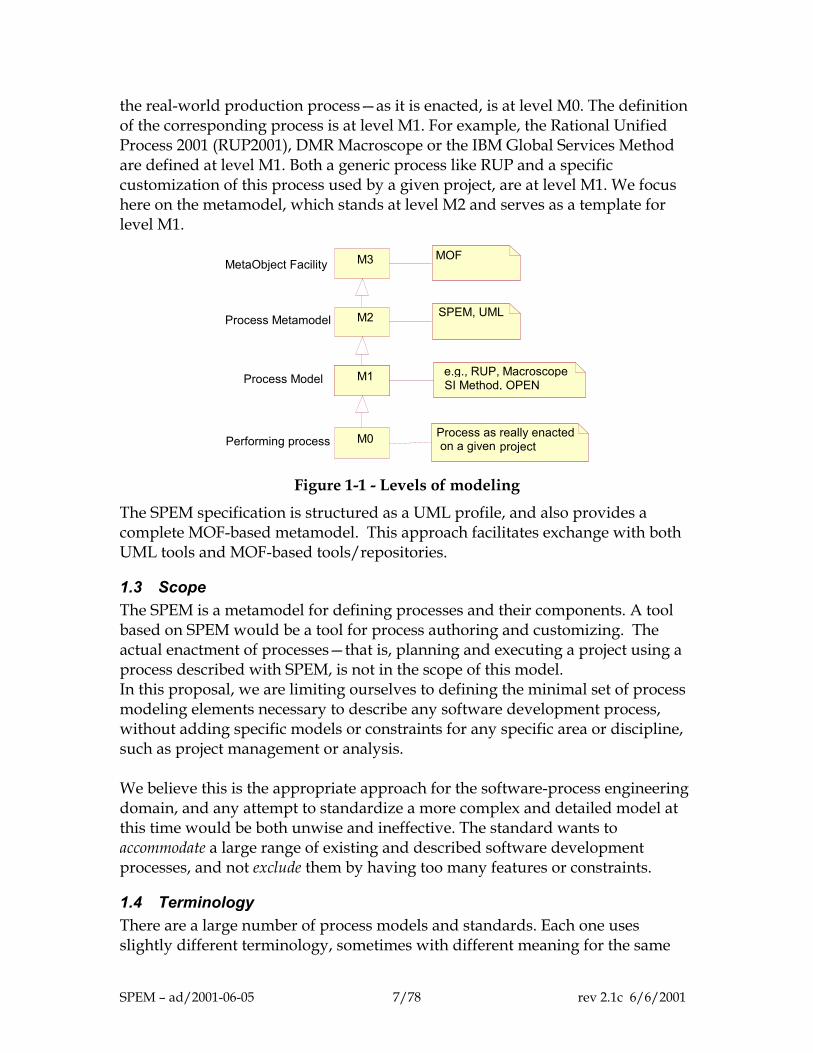
the real-world production process—as it is enacted, is at level M0. The definition of the corresponding process is at level M1. For example, the Rational Unified Process 2001 (RUP2001), DMR Macroscope or the IBM Global Services Method are defined at level M1. Both a generic process like RUP and a specific customization of this process used by a given project, are at level M1. We focus here on the metamodel, which stands at level M2 and serves as a template for level M1.
Process Metamodel
MOF
M0
M1M1M1M1
M2
M3
SPEM, UML
e.g., RUP, MacroscopeSI Method, OPEN
Process as really enacted on a given project
Process Model
Performing process
MetaObject Facility
Figure 1-1 - Levels of modeling
The SPEM specification is structured as a UML profile, and also provides a complete MOF-based metamodel. This approach facilitates exchange with both UML tools and MOF-based tools/repositories.
1.3 Scope The SPEM is a metamodel for defining processes and their components. A tool based on SPEM would be a tool for process authoring and customizing. The actual enactment of processes—that is, planning and executing a project using a process described with SPEM, is not in the scope of this model. In this proposal, we are limiting ourselves to defining the minimal set of process modeling elements necessary to describe any software development process, without adding specific models or constraints for any specific area or discipline, such as project management or analysis. We believe this is the appropriate approach for the software-process engineering domain, and any attempt to standardize a more complex and detailed model at this time would be both unwise and ineffective. The standard wants to accommodate a large range of existing and described software development processes, and not exclude them by having too many features or constraints.
1.4 Terminology There are a large number of process models and standards. Each one uses slightly different terminology, sometimes with different meaning for the same
SPEM – ad/2001-06-05 7/78 rev 2.1c 6/6/2001
English word or phrase. For example, a ‘phase’ in Fusion [13] is called a ‘core workflow’ in the Rational Unified Process (RUP) [1] and a ‘domain’ in IBM’s Global Services Method. We will designate it as a ‘discipline’ here. OPEN [4] and the Rational Unified Process [1] both use the word ‘activity’ but with a different meaning. We have provided “translations” (aliases or synonyms) to help in understanding. This also allows the naming of various process elements by the appropriate term in various languages: Japanese, French, and so on. See Annex 1 for a comparison table and Chapter 15 for the Glossary.
1.5 Relationships to Other OMG Specifications
UML
The Unified Modeling Language (UML) is a graphical language for modeling discrete systems. Although the UML is not necessarily tied to any particular application area or modeling process, its greatest applicability is in the area of object-oriented software design. Version 1.1 of the UML was submitted to the Object Management Group in September 1997 in response to an OMG RFP requesting a standard approach to object-oriented modeling. The proposal was ratified by the OMG in November 1997. Version 1.3 of the UML was finalized in June 1999. UML 1.4 (January 2001) is the version referred to throughout this document. The UML is defined by a metamodel, which is itself defined as an instance of the MOF (Meta-Object Facility) metametamodel. A subset of the UML graphical notation is used to depict this metamodel. The SPEM metamodel is defined similarly, and is formally defined as an extension of a subset of UML called SPEM_Foundation. Chapter 3 describes SPEM_Foundation in detail. The purpose of the Software Process Engineering Model (SPEM) is to support the definition of software development processes specifically including those processes that involve or mandate the use of UML, such as the Rational Unified Process®.
UML Profile
A UML profile is a kind of variant of UML that uses the extension mechanisms of UML in a standardized way, for a particular purpose. The UML 1.4 semantics (OMG document ad/01-02-13)) provides the following definition in the section “2.14.4 Semantics”:
A profile stereotype of Package contains one or more related extensions of standard UML semantics (refer to Section 2.6, “Extension Mechanisms”). These are normally intended to customize UML for a particular domain or purpose. Profiles can contain stereotypes, tag definitions, and constraints. They
SPEM – ad/2001-06-05 8/78 rev 2.1c 6/6/2001
can also contain data types that are used by tag definitions for informally declaring the types of the values that can be associated with tag definitions. In addition, a profile package can specify a related model library and identify a subset of the UML metamodel that is applicable for the profile. In principle, profiles merely refine the standard semantics of UML by adding further constraints and interpretations that capture domain-specific semantics and modeling patterns. They do not add any new fundamental concepts.
The SPEM is defined both as a metamodel and as a UML profile, which allows SPEM modelers to use the UML as a concrete notation. Chapter 12 of this proposal discusses the profile.
MOF 1.3 and XMI
The Meta-Object Facility (MOF) is the OMG's adopted technology for defining metadata and representing it as CORBA objects. The MOF 1.3 specification was finalized in September 1999 (OMG document ad/99-09-05). A MOF metamodel defines the abstract syntax of the metadata in the MOF representation of a model. The MOF model itself describes the abstract syntax for representing MOF metamodels. MOF metamodels can be represented using a subset of UML syntax. In addition to defining SPEM as a UML profile, it is defined as a MOF metamodel, based on a subset of UML. This gives a more restricted version of SPEM, in which the basic SPE elements can be described, without some of the diagramming and structuring facilities, which are added by the profile version of SPEM. Chapter 12 describes the additional facilities gained when SPEM is treated as a UML profile. XMI (XML Metadata Interchange) is the OMG's adopted technology for interchanging models in a serialized form (OMG document ad/98-10-05). XMI version 1.1 was formally adopted by the OMG in February 2000 (OMG document ad/99-10-04). XMI focuses on the interchange of MOF metadata; that is, metadata conforming to a MOF metamodel. XMI is based on the W3C's eXtensible Markup Language (XML) and has two major components:
• The XML DTD Production Rules for producing XML Document Type Definitions (DTDs) for XMI encoded metadata. XMI DTDs serve as syntax specifications for XML documents, and allow generic XML tools to be used to compose and validate XMI documents.
SPEM – ad/2001-06-05 9/78 rev 2.1c 6/6/2001
• The XML Document Production Rules for encoding metadata into an XML compatible format. The production rules can be applied in reverse to decode XMI documents and reconstruct the metadata.
XMI can be used to manipulate the SPEM metamodel as follows:
• to create a SPEM Document Type Definition
• to transfer process models based on SPEM as XML documents, either by describing the model as a direct SPEM instance (usage of the SPEM DTD) or by describing it as a UML model conforming to the UML profile for SPEM (usage of the UML DTD)
• to transform the SPEM metamodel itself into an XML document, based on the MOF DTD, for interchange between MOF-compliant repositories.
Chapter 14 of this document describes the use of XMI to interchange SPEM-based models.
Workflow
Within the OMG there are three initiatives that come under this heading. The first is the Joint Workflow Management Facility (OMG document bom/99-03-01). The scope of this facility is workflow enactment and it supports Workflow Client Applications, Interoperability, and Process Monitoring as described in the Workflow Reference Model. None of these areas overlaps the SPE submission, which addresses the domain of process description, not process enactment. The second is the Workflow Resource Assignment Interfaces RFP (OMG document bom/2000-01-03), which asks for submissions to extend the capabilities of the adopted workflow management specification in the areas of the assignment and selection of resources. The scope of this facility is also process enactment and so does not overlap the SPEM submission. The third area of interest is Process Definition. At this time no request for proposals has been issued. The matter is still under consideration, pending discussions within the UML RTF and the UML 2.0 working group about how UML Activity Diagrams will be supported and/or extended. This discussion somewhat overlaps the scope of the current submission.
Proof of Concept
The (meta)model and the UML Profile presented here supports at least the Rational Unified Process, DMR Macroscope, IBM's Global Services Method and the Unisys QuadCycle method. Examples throughout the text show how particular elements in the model are used in these and other processes. The
SPEM – ad/2001-06-05 10/78 rev 2.1c 6/6/2001
SPEM is supported by the Rational Process Workbench (RPW), which is a process authoring tool based on UML. The SPEM profile has been implemented using the “Objecteering/UML Profile Builder” tool of SOFTEAM, and then applied to the “Objecteering/UML Modeler” tool, which has been used as a “SPEM modeler” to represent various processes. All the SPEM extensions have been implemented with most of the SPEM well-formedness rules. The SPEM metamodel server has been generated in the Unisys XMI/MOF tools. Finally see Annex 2 for an example based on the DMR Macroscope.
1.6 Compliance points When specifying their compliance to SPEM, vendors should refer to the compliance points defined in this section, and not loosely say they are “SPEM compliant.” Being compliant to one point means that all elements belonging to this point are implemented. As a general rule, all elements defined in the SPEM metamodel (chapters 5 to 10) shall be supported except for the following optional elements:
• Kinds of Guidance (see section 6.2) • Steps (see section 8.3) • InformationElement (see section 8.1) • Discipline (see section 9.4)
Also it is not mandated that a SPEM implementation use the same terminology. Other terminologies, and natural languages other than English, can be used. In this case, a correspondence list must present a mapping of this terminology with the SPEM terminology. The compliance points are as follow :
• UML Profile for SPEM : the compliant implementation shall implement all the UML parts extended by SPEM, and shall define all the SPEM extensions. The compliant specification should specify whether it implements the SPEM constraints by an automated check or not. A SPEM Profile compliant implementation shall provide the UML XMI exchange mechanism that supports all UML features extended by SPEM, and the UML extension mechanism (UML Profiles).
• Metamodel : the compliant implementation shall support the SPEM Metamodel, except possibly some of the optional elements as noted above.
• MOF/XMI DTD : The compliant specification should implement all the MOF based metamodel provided by the SPEM specification. It shall implement the XMI DTD specified by the SPEM standard.
• Notation : The compliant implementation shall recognizably support all the notation defined by the SPEM specification.
Any combination of the four compliance points can be used.
SPEM – ad/2001-06-05 11/78 rev 2.1c 6/6/2001
Examples
Implementers declare their SPEM compliance in the following form: • The XXX tool is SPEM compliant (UML Profile for SPEM without
constraint checks implementation, Notation). • The XXX tool is SPEM compliant (Metamodel, MOF/XMI DTD, Notation). • The XXX tool is SPEM compliant (Notation).
This list is not exhaustive.
SPEM – ad/2001-06-05 12/78 rev 2.1c 6/6/2001
2 Mapping to RFP Requirements
2.1 Mandatory Requirements:
Four-layer Architecture
• Submissions shall conform to the four-layer architecture defined by the OMG. SPEM sits at level M2 in the four-layer architecture and further details are found in section 1.2 and chapter 12.
Relationship to UML and MOF
• Metamodels shall be clearly positioned in relation to the UML metamodel and built using the MOF meta-metamodel. Relationships between these metamodels shall be identified and specified.
The SPEM metamodel is defined using a subset of UML notation in a similar way to UML itself (more precisely, to the physical model defined in the UML 1.4 specification) and to MOF. This subset of UML notation corresponds to the facilities supported by MOF and its semantics are defined by the MOF 1.3 specification.
XMI DTD
• A submission shall include an XMI DTD for a submitted metamodel. An XMI DTD is included in chapter 14.
Basic Concepts
• The metamodel shall address at least the following concepts: Tasks, Techniques, Roles, Products, Phases. Responses are not required to use these exact names.
The SPEM supports the description of these concepts (not their enactment) in the following ways:
• Tasks are modeled by Activity (see section 8.3) • Techniques are modeled by Guidance (see section 6.2) or Activity (see section
8.3) • Roles are modeled by ProcessRole (see section 8.4) • Products are modeled by WorkProduct (see section 8.1) • Phases are modeled by Phase (see section 10.1)
SPEM – ad/2001-06-05 13/78 rev 2.1c 6/6/2001
Annex 1 shows a mapping of SPEM terms with those of various published processes.
Process Examples
• Submissions shall submit two or more examples of processes that use the submitted metamodel.
SPEM underpins the Rational Unified Process and IBM's family of methods, including the Global Services Method deployed throughout IBM Global Services. See also an example extracted from the DMR Macroscope in Annex 2.
Process Patterns and/or Components
• Submissions are required to define constructs that enable the creation and use of reusable process patterns and/or components.
The construct ProcessComponent, described in more detail in section 9.1, represents such a reusable piece of process. Also the construct ProcessPerformer, described in more detail in section 8.4, represents a reusable set of WorkDefinitions and Activities.
Glossary
• Submissions shall include a full glossary of SPE terms. These terms shall have a clearly-defined relationship to the constructs defined in the submitted SPE metamodel.
Chapter 15 of this document provides a glossary of the main terms used in the metamodel.
Support for UML
• The facility shall support the use of UML for software engineering modeling and process modeling. A specification of relationships between SPE constructs and UML constructs is required, wherever such relationships exist. Facilities providing help in UML usage, depending on the activity and on the development context, shall also be defined.
The SPEM can be used to define all kinds of processes, including those focused on the specific use of UML. Instances of Guidance subclasses for describing UML practices and tools would be created for an UML-specific process.
Categories
• A submission shall provide the facility to define a standardized set of categories. A submission shall provide the ability to classify all process elements using these categories.
SPEM – ad/2001-06-05 14/78 rev 2.1c 6/6/2001
The class Package, explained in section 9.1, supports a categorization of process elements. By using the categorizes dependency described in chapter 7, it supports multiple, overlapping categorization schemes. The class Discipline supports a categorization based on a partitioning of the Activities.
Natural Language Translation
• A submission shall be organized so that a process can readily be translated between different natural languages without losing its structure.
With each ModelElement can be associated one or more ExternalDescription. Each ExternalDescription has an attribute ‘language’ specifying which natural language is used for the name and the description of the ModelElement. See section 6.1.
Graphical Notation
• Responses shall include graphical notations or default to UML notations. Where a response makes notation recommendations other than UML it shall show the relationship between those recommendations and other established process modeling notations; for example, IDEF0. If a recommended notation is not UML-based, responses shall explain why a different notation is better.
The SPEM offers graphical notations that are similar to those of UML for depicting software engineering processes. Special icons are used to denote process-related concepts—artifacts, roles, activities, and so on—to make these diagrams more expressive. Chapter 13 of this document defines a notation for SPEM process modeling that extends UML notation with process-related icons. Compared to IDEF0, which focuses mostly on activities, their decomposition, and their sequencing, a UML-like set of process diagrams gives a much wider palette of expression and allows the use of existing UML-supporting tools to model the process.
2.2 Optional Requirements
Submission as a UML Profile
• A submission may define a UML profile. As well as being defined by a stand-alone metamodel, this submission is presented as a UML profile. Chapter 12 discusses this profile and shows how the
SPEM – ad/2001-06-05 15/78 rev 2.1c 6/6/2001
constructs in the stand-alone metamodel are mapped into the profile constructs. Note that the UML profile provides significantly more facilities than the stand-alone metamodel, in particular the use of various notations.
Definition of Process Patterns and/or Components
• A submission may define actual process patterns and/or components. Examples of actual process components are included in the SPEM, in Annex 2.
Reification of UML Profile Concept
• Submissions may reify the UML profile concept. The way in which profiles may constrain the development process, notations or tools may be emphasized. Relationships between profiles and activities and between profiles and work products may be clarified.
A UML Profile can be represented as a kind of Guidance, as described in section 6.2.
SPEM – ad/2001-06-05 16/78 rev 2.1c 6/6/2001
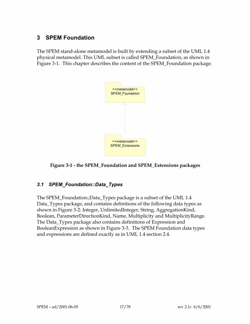
3 SPEM Foundation The SPEM stand-alone metamodel is built by extending a subset of the UML 1.4 physical metamodel. This UML subset is called SPEM_Foundation, as shown in Figure 3-1. This chapter describes the content of the SPEM_Foundation package.
SPEM_Foundat ion<<metamodel>>
SPEM_Extensions<<metamodel>>
Figure 3-1 - the SPEM_Foundation and SPEM_Extensions packages
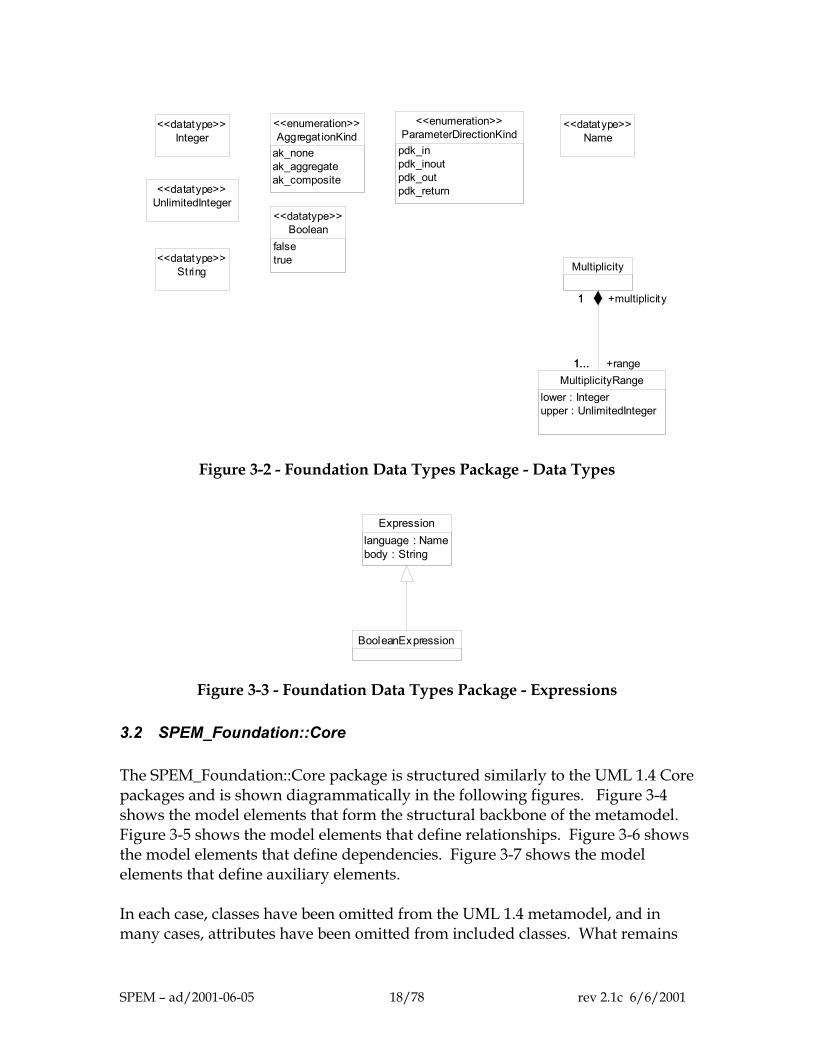
3.1 SPEM_Foundation::Data_Types The SPEM_Foundation:;Data_Types package is a subset of the UML 1.4 Data_Types package, and contains definitions of the following data types as shown in Figure 3-2: Integer, UnlimitedInteger, String, AggregationKind, Boolean, ParameterDirectionKind, Name, Multiplicity and MultiplicityRange. The Data_Types package also contains definitions of Expression and BooleanExpression as shown in Figure 3-3. The SPEM Foundation data types and expressions are defined exactly as in UML 1.4 section 2.4.
SPEM – ad/2001-06-05 17/78 rev 2.1c 6/6/2001
Aggregat ionKindak_noneak_aggregateak_composite
<<enumeration>>
Booleanfalsetrue
<<datatype>>
Name<<datatype>>
Integer<<datatype>>
ParameterDirectionKindpdk_inpdk_inoutpdk_outpdk_return
<<enumeration>>
String<<datatype>>
MultiplicityRangelower : Integerupper : UnlimitedInteger
Multiplicity
1...
1
+range1...
+multiplicity1
UnlimitedInteger<<datatype>>
Figure 3-2 - Foundation Data Types Package - Data Types
BooleanExpression
Expressionlanguage : Namebody : String
Figure 3-3 - Foundation Data Types Package - Expressions
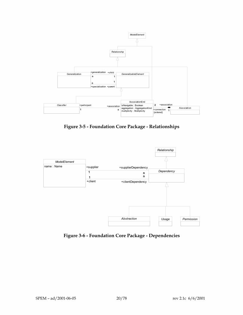
3.2 SPEM_Foundation::Core The SPEM_Foundation::Core package is structured similarly to the UML 1.4 Core packages and is shown diagrammatically in the following figures. Figure 3-4 shows the model elements that form the structural backbone of the metamodel. Figure 3-5 shows the model elements that define relationships. Figure 3-6 shows the model elements that define dependencies. Figure 3-7 shows the model elements that define auxiliary elements. In each case, classes have been omitted from the UML 1.4 metamodel, and in many cases, attributes have been omitted from included classes. What remains
SPEM – ad/2001-06-05 18/78 rev 2.1c 6/6/2001
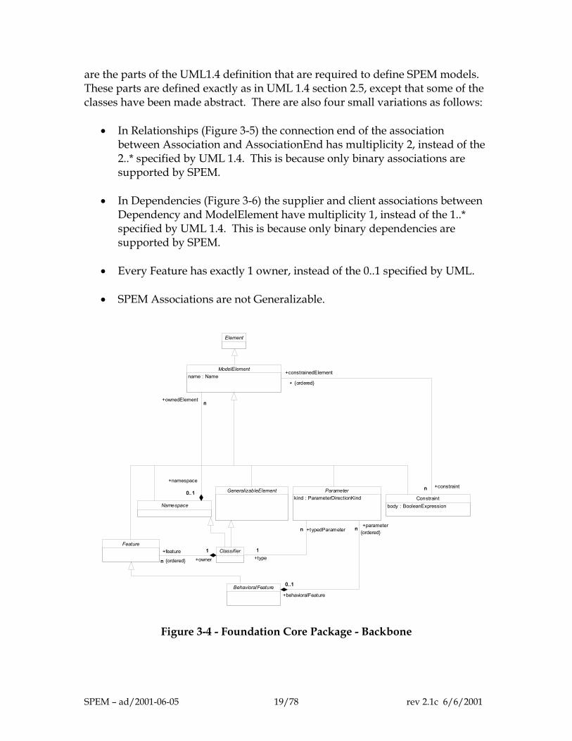
are the parts of the UML1.4 definition that are required to define SPEM models. These parts are defined exactly as in UML 1.4 section 2.5, except that some of the classes have been made abstract. There are also four small variations as follows:
• In Relationships (Figure 3-5) the connection end of the association
between Association and AssociationEnd has multiplicity 2, instead of the 2..* specified by UML 1.4. This is because only binary associations are supported by SPEM.
• In Dependencies (Figure 3-6) the supplier and client associations between
Dependency and ModelElement have multiplicity 1, instead of the 1..* specified by UML 1.4. This is because only binary dependencies are supported by SPEM.
• Every Feature has exactly 1 owner, instead of the 0..1 specified by UML.
• SPEM Associations are not Generalizable.
Element
GeneralizableElement
NamespaceConstraint
body : BooleanExpression
ModelElementname : Name
0..1
n
+namespace
0..1
+ownedElementn
n
*
+constraintn
+constrainedElement
* {ordered}
BehavioralFeature
Feature
Parameterkind : ParameterDirectionKind
0..1
n
+behavioralFeature
0..1
+parametern{ordered}
Classifier
n
1+feature
n {ordered} +owner
1
n
1
+typedParametern
+type1
Figure 3-4 - Foundation Core Package - Backbone
SPEM – ad/2001-06-05 19/78 rev 2.1c 6/6/2001
Relationship
AssociationClassifier
AssociationEndisNavigable : Booleanaggregation : AggregationKindmultiplicity : Multiplicity
2
1+connection
2
{ordered}
+association
11 n
+participant
1+association
n
GeneralizableElementGeneralizationn 1
+generalizat ion
n+child
1
1n+parent
1
+specializationn
ModelElement
Figure 3-5 - Foundation Core Package - Relationships
Usage Permission
ModelElementname : Name
Dependency1 n
+supplier1
+supplierDependency
n1 n
+client1
+clientDependency
n
Relationship
Abstraction
Figure 3-6 - Foundation Core Package - Dependencies
SPEM – ad/2001-06-05 20/78 rev 2.1c 6/6/2001
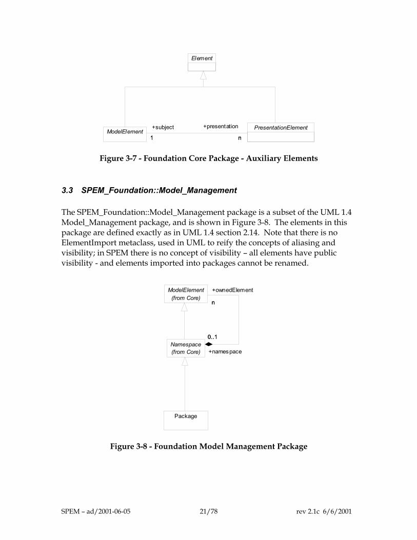
Element
PresentationElementModelElement
n1
+presentation
n
+subject
1
Figure 3-7 - Foundation Core Package - Auxiliary Elements
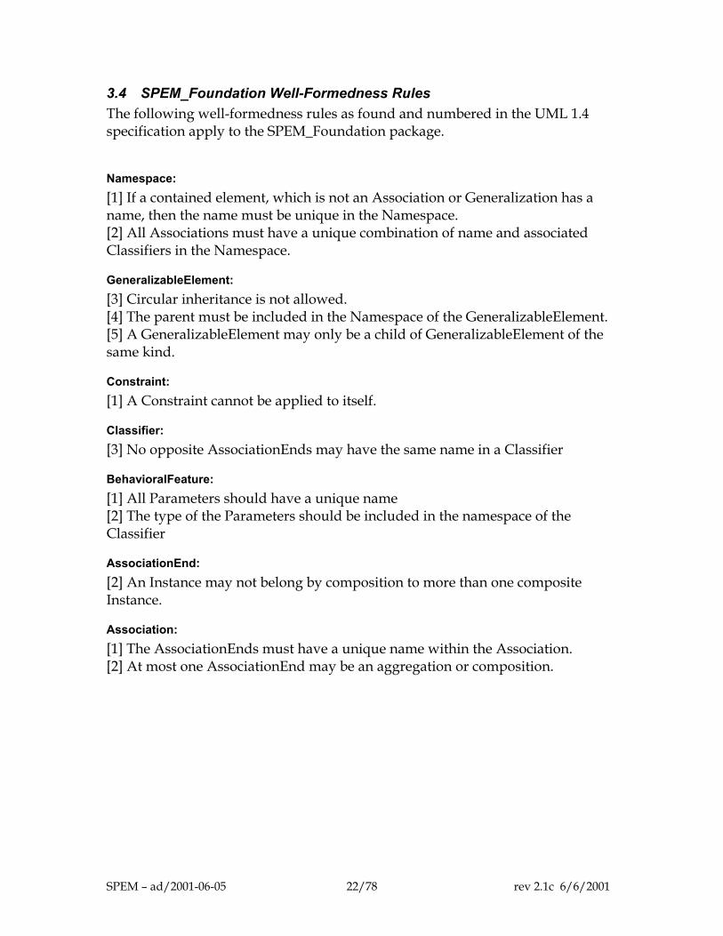
3.3 SPEM_Foundation::Model_Management The SPEM_Foundation::Model_Management package is a subset of the UML 1.4 Model_Management package, and is shown in Figure 3-8. The elements in this package are defined exactly as in UML 1.4 section 2.14. Note that there is no ElementImport metaclass, used in UML to reify the concepts of aliasing and visibility; in SPEM there is no concept of visibility – all elements have public visibility - and elements imported into packages cannot be renamed.
ModelElement(from Core)
Namespace(from Core)
n
0..1
+ownedElement
n
+namespace
0..1
Package
Figure 3-8 - Foundation Model Management Package
SPEM – ad/2001-06-05 21/78 rev 2.1c 6/6/2001
3.4 SPEM_Foundation Well-Formedness Rules The following well-formedness rules as found and numbered in the UML 1.4 specification apply to the SPEM_Foundation package.
Namespace: [1] If a contained element, which is not an Association or Generalization has a name, then the name must be unique in the Namespace. [2] All Associations must have a unique combination of name and associated Classifiers in the Namespace.
GeneralizableElement: [3] Circular inheritance is not allowed. [4] The parent must be included in the Namespace of the GeneralizableElement. [5] A GeneralizableElement may only be a child of GeneralizableElement of the same kind.
Constraint: [1] A Constraint cannot be applied to itself.
Classifier: [3] No opposite AssociationEnds may have the same name in a Classifier
BehavioralFeature: [1] All Parameters should have a unique name [2] The type of the Parameters should be included in the namespace of the Classifier
AssociationEnd: [2] An Instance may not belong by composition to more than one composite Instance.
Association: [1] The AssociationEnds must have a unique name within the Association. [2] At most one AssociationEnd may be an aggregation or composition.
SPEM – ad/2001-06-05 22/78 rev 2.1c 6/6/2001
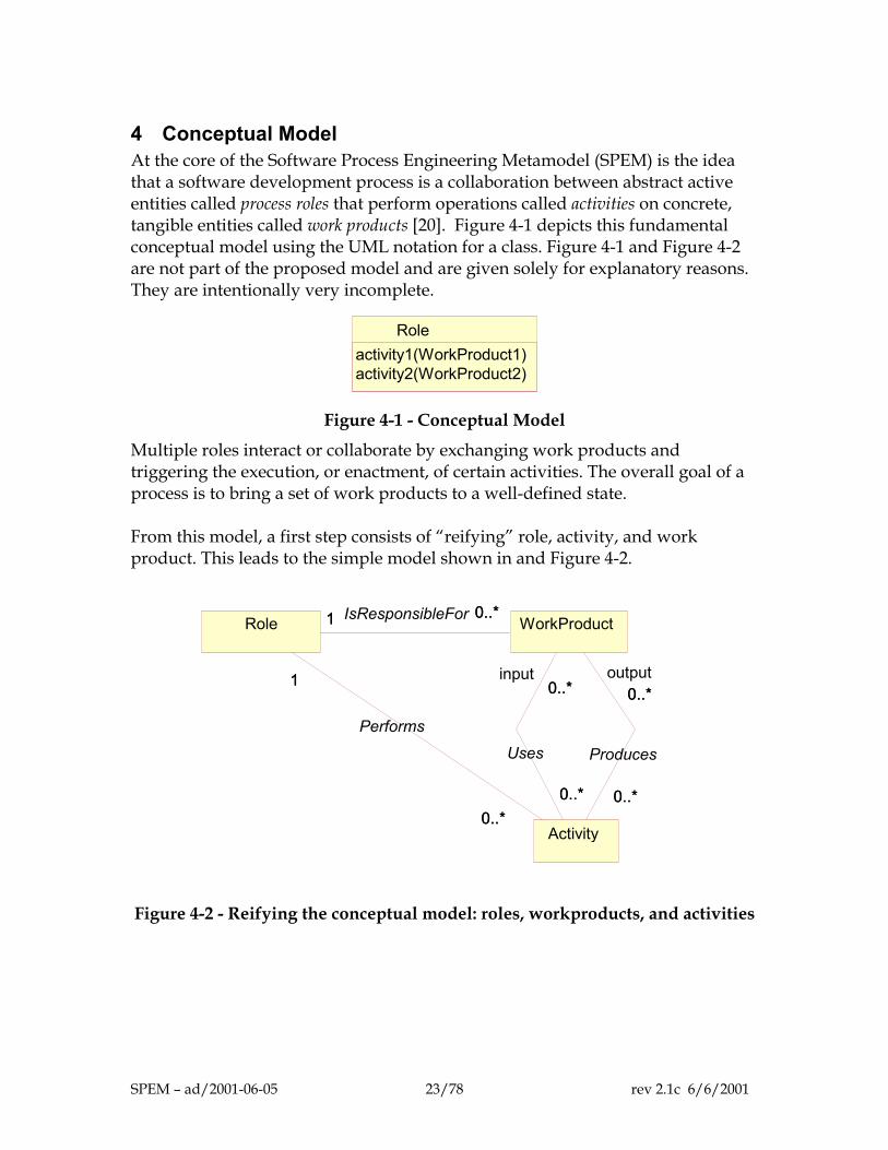
4 Conceptual Model At the core of the Software Process Engineering Metamodel (SPEM) is the idea that a software development process is a collaboration between abstract active entities called process roles that perform operations called activities on concrete, tangible entities called work products [20]. Figure 4-1 depicts this fundamental conceptual model using the UML notation for a class. Figure 4-1 and Figure 4-2 are not part of the proposed model and are given solely for explanatory reasons. They are intentionally very incomplete.
Roleactivity1(WorkProduct1)activity2(WorkProduct2)
Figure 4-1 - Conceptual Model
Multiple roles interact or collaborate by exchanging work products and triggering the execution, or enactment, of certain activities. The overall goal of a process is to bring a set of work products to a well-defined state. From this model, a first step consists of “reifying” role, activity, and work product. This leads to the simple model shown in and Figure 4-2.
Role
Activity0..*
1
0..*
1
Performs
WorkProduct0..*1 0..*1 IsResponsibleFor
0..*
0..*
0..*
input0..*
Uses
0..*
0..*
0..*
output 0..*
Produces
Figure 4-2 - Reifying the conceptual model: roles, workproducts, and activities
SPEM – ad/2001-06-05 23/78 rev 2.1c 6/6/2001
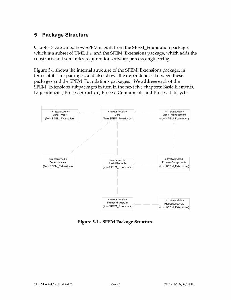
5 Package Structure Chapter 3 explained how SPEM is built from the SPEM_Foundation package, which is a subset of UML 1.4, and the SPEM_Extensions package, which adds the constructs and semantics required for software process engineering. Figure 5-1 shows the internal structure of the SPEM_Extensions package, in terms of its sub-packages, and also shows the dependencies between these packages and the SPEM_Foundations packages. We address each of the SPEM_Extensions subpackages in turn in the next five chapters: Basic Elements, Dependencies, Process Structure, Process Components and Process Lifecycle.
Data_Types<<metamodel>>
(from SPEM_Foundation)Core
<<metamodel>>
(from SPEM_Foundation)Model_Management
<<metamodel>>
(from SPEM_Foundation)
BasicElements<<metamodel>>
(from SPEM_Extensions)
ProcessComponents<<metamodel>>
(from SPEM_Extensions)
ProcessStructure<<metamodel>>
(from SPEM_Extensions)ProcessLifecycle<<metamodel>>
(from SPEM_Extensions)
Dependencies<<metamodel>>
(from SPEM_Extensions)
Figure 5-1 - SPEM Package Structure
SPEM – ad/2001-06-05 24/78 rev 2.1c 6/6/2001
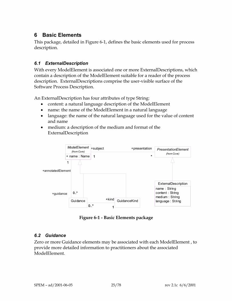
6 Basic Elements This package, detailed in Figure 6-1, defines the basic elements used for process description.
6.1 ExternalDescription With every ModelElement is associated one or more ExternalDescriptions, which contain a description of the ModelElement suitable for a reader of the process description. ExternalDescriptions comprise the user-visible surface of the Software Process Description. An ExternalDescription has four attributes of type String:
• content: a natural language description of the ModelElement • name: the name of the ModelElement in a natural language • language: the name of the natural language used for the value of content
and name • medium: a description of the medium and format of the
ExternalDescription
ExternalDescriptionname : Stringcontent : Stringmedium : Stringlanguage : String
PresentationElement(f rom Co re)
GuidanceKind
ModelElement(from Core)
+ name : Name 1 *
+subject
1
+presentation
*
Guidance0..* 10..*
+kind
1
1
0..*
+annotatedElement
1
+guidance 0..*
Figure 6-1 - Basic Elements package
6.2 Guidance Zero or more Guidance elements may be associated with each ModelElement , to provide more detailed information to practitioners about the associated ModelElement.
SPEM – ad/2001-06-05 25/78 rev 2.1c 6/6/2001
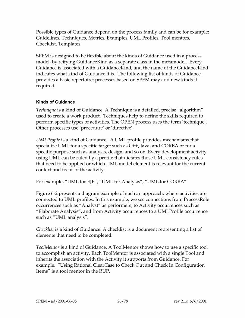
Possible types of Guidance depend on the process family and can be for example: Guidelines, Techniques, Metrics, Examples, UML Profiles, Tool mentors, Checklist, Templates. SPEM is designed to be flexible about the kinds of Guidance used in a process model, by reifying GuidanceKind as a separate class in the metamodel. Every Guidance is associated with a GuidanceKind, and the name of the GuidanceKind indicates what kind of Guidance it is. The following list of kinds of Guidance provides a basic repertoire; processes based on SPEM may add new kinds if required.
Kinds of Guidance
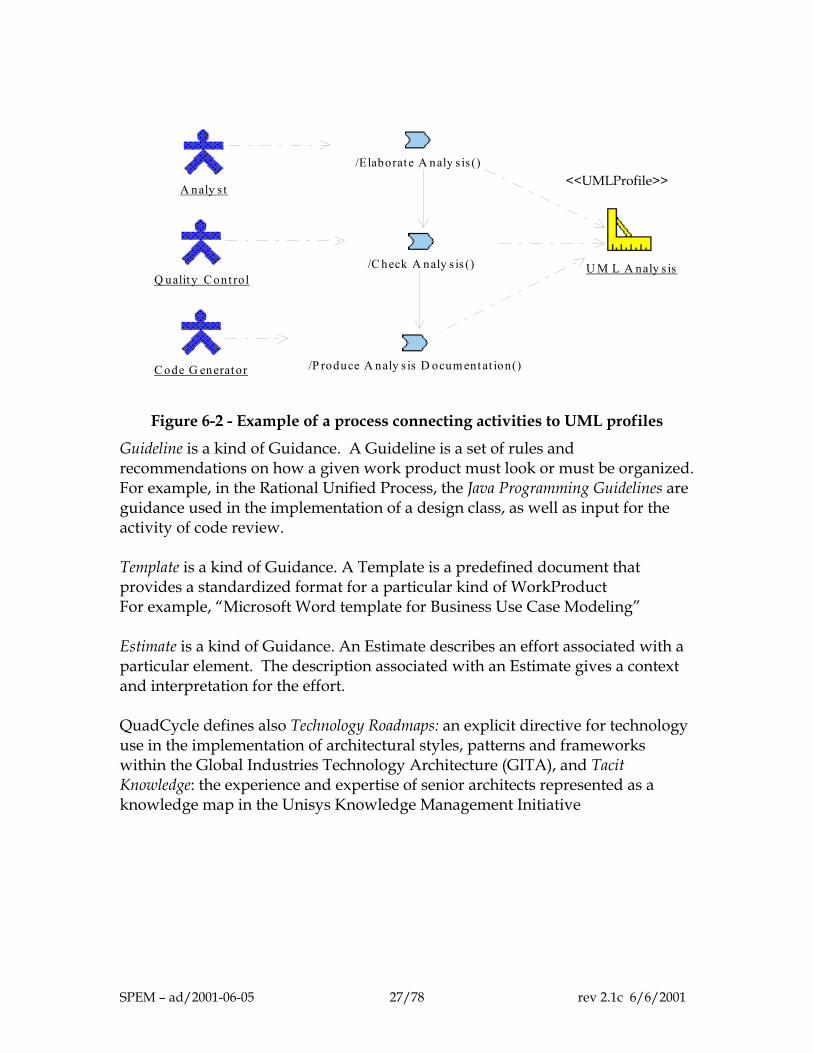
Technique is a kind of Guidance. A Technique is a detailed, precise “algorithm” used to create a work product. Techniques help to define the skills required to perform specific types of activities. The OPEN process uses the term ‘technique’. Other processes use ‘procedure’ or ‘directive’. UMLProfile is a kind of Guidance. A UML profile provides mechanisms that specialize UML for a specific target such as C++, Java, and CORBA or for a specific purpose such as analysis, design, and so on. Every development activity using UML can be ruled by a profile that dictates those UML consistency rules that need to be applied or which UML model element is relevant for the current context and focus of the activity. For example, “UML for EJB”, “UML for Analysis”, “UML for CORBA” Figure 6-2 presents a diagram example of such an approach, where activities are connected to UML profiles. In this example, we see connections from ProcessRole occurrences such as “Analyst” as performers, to Activity occurrences such as “Elaborate Analysis”, and from Activity occurrences to a UMLProfile occurrence such as “UML analysis”. Checklist is a kind of Guidance. A checklist is a document representing a list of elements that need to be completed. ToolMentor is a kind of Guidance. A ToolMentor shows how to use a specific tool to accomplish an activity. Each ToolMentor is associated with a single Tool and inherits the association with the Activity it supports from Guidance. For example, “Using Rational ClearCase to Check Out and Check In Configuration Items” is a tool mentor in the RUP.
SPEM – ad/2001-06-05 26/78 rev 2.1c 6/6/2001
/Elaborat e A naly s is ()
/C heck A naly s is ()
/P roduce A naly s is D ocum ent at ion()
A naly s t
Q ualit y C ont rol
C ode G enerat or
U M L A naly s is
<<UMLProfile>>
Figure 6-2 - Example of a process connecting activities to UML profiles
Guideline is a kind of Guidance. A Guideline is a set of rules and recommendations on how a given work product must look or must be organized. For example, in the Rational Unified Process, the Java Programming Guidelines are guidance used in the implementation of a design class, as well as input for the activity of code review. Template is a kind of Guidance. A Template is a predefined document that provides a standardized format for a particular kind of WorkProduct For example, “Microsoft Word template for Business Use Case Modeling” Estimate is a kind of Guidance. An Estimate describes an effort associated with a particular element. The description associated with an Estimate gives a context and interpretation for the effort. QuadCycle defines also Technology Roadmaps: an explicit directive for technology use in the implementation of architectural styles, patterns and frameworks within the Global Industries Technology Architecture (GITA), and Tacit Knowledge: the experience and expertise of senior architects represented as a knowledge map in the Unisys Knowledge Management Initiative
SPEM – ad/2001-06-05 27/78 rev 2.1c 6/6/2001
7 Dependencies
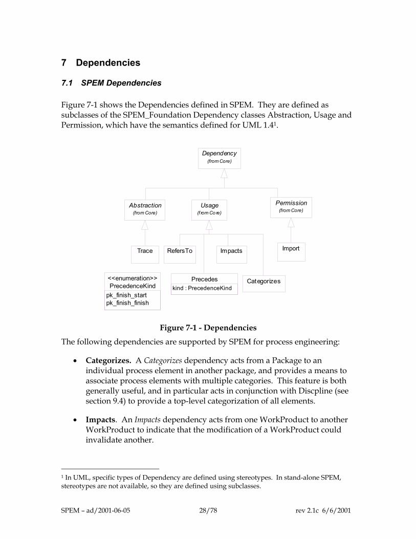
7.1 SPEM Dependencies Figure 7-1 shows the Dependencies defined in SPEM. They are defined as subclasses of the SPEM_Foundation Dependency classes Abstraction, Usage and Permission, which have the semantics defined for UML 1.41.
Dependency(from Core)
Abstraction(from Core)
Usage(f rom Co re)
Permission(from Core)
Trace RefersTo Impacts Import
Precedeskind : PrecedenceKindPrecedenceKind
pk_finish_startpk_finish_finish
<<enumeration>> Categorizes
Figure 7-1 - Dependencies
The following dependencies are supported by SPEM for process engineering:
• Categorizes. A Categorizes dependency acts from a Package to an individual process element in another package, and provides a means to associate process elements with multiple categories. This feature is both generally useful, and in particular acts in conjunction with Discpline (see section 9.4) to provide a top-level categorization of all elements.
• Impacts. An Impacts dependency acts from one WorkProduct to another WorkProduct to indicate that the modification of a WorkProduct could invalidate another.
1 In UML, specific types of Dependency are defined using stereotypes. In stand-alone SPEM, stereotypes are not available, so they are defined using subclasses.
SPEM – ad/2001-06-05 28/78 rev 2.1c 6/6/2001
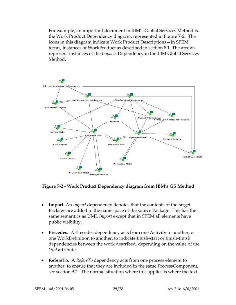
For example, an important document in IBM’s Global Services Method is the Work Product Dependency diagram, represented in Figure 7-2. The icons in this diagram indicate Work Product Descriptions—in SPEM terms, instances of WorkProduct as described in section 8.1. The arrows represent instances of the Impacts Dependency in the IBM Global Services Method.
Non-Functional Requirements
Performance Model
Deployment Unit
Architectural Template
Reference Architecture Fit/Gap Analysis
Standards
Component Model
Architecture Overview Diagram
Use Case Model
Class Diagram
Operational Model
Current IT EnvironmentService Level Characteristic Analysis
Technical Prototype
System Context
UI Design GuidelinesUI Conceptual Model
Viability Assessment
Figure 7-2 - Work Product Dependency diagram from IBM's GS Method
• Import. An Import dependency denotes that the contents of the target Package are added to the namespace of the source Package. This has the same semantics as UML Import except that in SPEM all elements have public visibility.
• Precedes. A Precedes dependency acts from one Activity to another, or one WorkDefinition to another, to indicate finish-start or finish-finish dependencies between the work described, depending on the value of the kind attribute.
• RefersTo. A RefersTo dependency acts from one process element to another, to ensure that they are included in the same ProcessComponent, see section 9.2. The normal situation where this applies is where the text
SPEM – ad/2001-06-05 29/78 rev 2.1c 6/6/2001
of one process element refers, by name or content, to another element. In order to ensure consistency of meaning of the text, a RefersTo dependency should be established to give an explicit structural representation of such a dependency, so that when the referring element is included in a ProcessComponent, the referred-to element must also be included.
• Trace. A Trace dependency acts between WorkDefinitions or InformationElements and is mainly used to trace requirements and changes across models. It has the same semantics as UML Trace.
7.2 Well-formedness rules
Categorizes: [1] The client must be a kind of Package context Categorizes inv:
self.client.oclIsKindOf(Package)
Impacts: [1] The supplier and client must be kinds of WorkProduct context Impacts inv:
self.supplier.oclIsKindOf(WorkProduct) and self.client.oclIsKindOf(WorkProduct)
Import: [1] The supplier and client must be kinds of Package context Import inv:
self.supplier.oclIsKindOf(Package) and self.client.oclIsKindOf(Package)
Precedes: [1] The supplier and client must be kinds of WorkDefinition context Precedes inv:
self.supplier.oclIsKindOf(WorkDefinition) and self.client.oclIsKindOf(WorkDefinition)
RefersTo: No additional rules.
Trace: No additional rules.
SPEM – ad/2001-06-05 30/78 rev 2.1c 6/6/2001
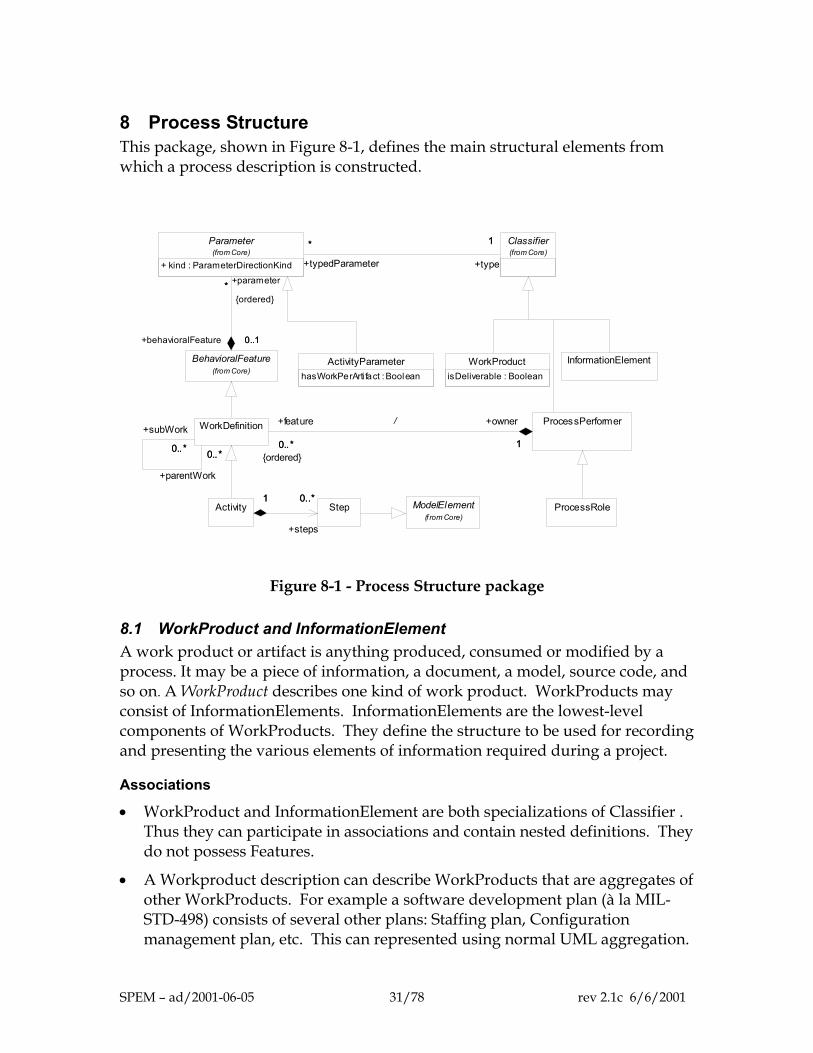
8 Process Structure This package, shown in Figure 8-1, defines the main structural elements from which a process description is constructed.
InformationElement
ProcessRole
Classifier(from Core)
Parameter(from Core)
+ kind : ParameterDirectionKind
1*
+type
1
+typedParameter
*
BehavioralFeature(from Core)
*
0..1
+parameter*{ordered}
+behavioralFeature 0..1
ModelElement(f rom Core)
StepActivity0..*1
+steps
0..*1
WorkProductisDeliverable : Boolean
ActivityParameterhasWorkPerArti fact : Boolean
WorkDefinition
0..* 0..*
+subWork
0..*
+parentWork
0..*
ProcessPerformer
0..* 1
+feature
0..*{ordered}
+owner
1
/
Figure 8-1 - Process Structure package
8.1 WorkProduct and InformationElement A work product or artifact is anything produced, consumed or modified by a process. It may be a piece of information, a document, a model, source code, and so on. A WorkProduct describes one kind of work product. WorkProducts may consist of InformationElements. InformationElements are the lowest-level components of WorkProducts. They define the structure to be used for recording and presenting the various elements of information required during a project.
Associations
• WorkProduct and InformationElement are both specializations of Classifier . Thus they can participate in associations and contain nested definitions. They do not possess Features.
• A Workproduct description can describe WorkProducts that are aggregates of other WorkProducts. For example a software development plan (à la MIL-STD-498) consists of several other plans: Staffing plan, Configuration management plan, etc. This can represented using normal UML aggregation.
SPEM – ad/2001-06-05 31/78 rev 2.1c 6/6/2001
Attributes
The isDeliverable attribute on WorkProduct is true if that WorkProduct is defined as a formal deliverable of the process.
Note
Deliverable is not a major model element in SPEM because not all WorkProducts are deliverable, and whether a WorkProduct is delivered or not may change during the enactment.
Examples
”Design Model” is a WorkProduct that describes design models, which are workproducts. “Software development plan” is a WorkProduct that is an aggregate of several other WorkProducts, such as documents and plans, designated by name; for example, “Risk Plan”.
Synonyms
‘Artifact’ is the term used in the RUP and QuadCyclefor the description of the WorkProduct; the IBM process uses the term ‘Work Product Description’. Other processes use the terms ‘deliverable’ or ‘product’.
8.2 WorkDefinition and ActivityParameter WorkDefinition is a kind of BehaviouralFeature that describes the work performed in the process. Its main subclass is Activity, but Phase, Iteration, and Lifecycle (in the Process Lifecycle package) are also subclasses of WorkDefinition. WorkDefinition is not an abstract class, and instances of WorkDefinition itself can be created to represent composite pieces of work that are further decomposed. It has explicit inputs and outputs referred to via ActivityParameter.
Associations
• A WorkDefinitions can be composed of other WorkDefinitions using the association called subWork.
• A WorkDefinition is related to the WorkProducts it uses through the ActivityParameter class, which specifies whether they are used as input or output. The work described in the WorkDefinition uses the input workproducts, and creates or updates the output workproducts.
• A WorkDefinition has an owner ProcessPerformer, representing the primary role that performs that WorkDefinition in the process. In the case of Activities carried out by an individual or small group, this will be a ProcessRole. In the case of higher-level WorkDefinitions this will often be a single instance of ProcessPerformer that corresponds to the complete Process.
SPEM – ad/2001-06-05 32/78 rev 2.1c 6/6/2001
Attributes
The attribute kind on Parameter is used to indicate whether the associated work product is an input, output, a modifiable input, or a returned value to the WorkDefinition. The attribute hasWorkPerArtifact indicates that multiple instances of the WorkDefinition are needed, one per instance of the corresponding WorkProduct. For example, Write the code of a class may have Coding standards and Class as inputs, but it is replicated once per class (not per coding standard). This attribute can be true for at most one ActivityParameter per WorkDefinition.
Note
The familiar concept of Work-Breakdown Structure (WBS) can be described using two SPEM constructs: 1. Decomposition using subWork provides the means to describe that one
WorkDefinition is composed of another and, therefore, the hierarchical nature of the WBS. When SPEM is represented as a UML Profile, subwork can be considered as an abstraction for the inclusion of the subsidiary WorkDefinitions on activity graphs, as explained in chapter 12.
2. The Precedes dependency provides the ability to sequence between elements of the WBS at the same level, see chapter 7.
Example
In the Fujitsu SDEM21 development process, there are 3 levels of WorkDefinition layers, the last of which corresponds to activities.
8.3 Activity and Step Activity is the main subclass of WorkDefinition. It describes a piece of work performed by one ProcessRoke: the tasks, operations, and actions that are performed by a role or with which the role may assist. An Activity may consist of atomic elements called Steps.
Associations
• Activity inherits from WorkDefinition the fact that it has input and output parameters, of type WorkProduct.
• An Activity is owned by a ProcessRole that is the performer (or owner) of the described activity. It may refer to additional ProcessRoles that are the assistants in the activity by including these as additional input parameters to the Activity.
• Although this is not explicitly prohibited, an Activity does not normally use the subWork structure inherited from WorkDefinition; instead decomposition
SPEM – ad/2001-06-05 33/78 rev 2.1c 6/6/2001
within Activity is done using Steps. A Step is described in the context of the enclosing Activity in terms of the ProcessRoles and WorkProducts it uses.
Examples
In the RUP, Find use case and actors is an example of Activity. It is decomposed in half a dozen “steps” in the RUP: Find actors, …., Check the results. In IBM’s Global Services Method, Specify Solution Requirements is an example of a WorkDefinition. It is decomposed into several “tasks”, modeled by SPEM’s Activity, such as Detail Usability Requirements.
Synonyms
The Rational Unified Process and QuadCycle use ‘activity’ composed of a partially ordered set of ‘steps’. The IBM process defines ‘activities’ that corresponds to SPEM WorkDefinition, consisting of ‘tasks’ and ‘subtasks’ that corresponds to SPEM Activities. OPEN uses ‘task’.
8.4 ProcessPerformer and ProcessRole A ProcessPerformer defines an owner for a set of WorkDefinitions in a process. ProcessPerformer has a subclass, ProcessRole. ProcessPerformer represents abstractly the “whole process” or one of its components, and is used to own WorkDefinitions that do not have a more specific owner. ProcessRole defines responsibilities over specific WorkProducts, and defines the roles that perform and assist in specific activities.
Associations
• ProcessPerformer is a specialization of Classifier, and thus may participate in inheritance relationships and associations within the process definition.
• A ProcessRole is responsible for a set of WorkProducts; this is modeled by creating M1-level associations between the ProcessRole and the relevant WorkProducts.
• A ProcessRole is the owner (performer) of Activities.
• A ProcessPerformer is the owner of higher level aggregate WorkDefinitions that cannot be associated with individual ProcessRoles.
Synonyms
ProcessRole is called ‘role’ in the IBM Global Services Method, DMR Macroscope and in OPEN [4], and it was called ‘worker’ in the Rational Unified Process [1, 3], prior to RUP 2001. We have also encountered ‘agent’.
SPEM – ad/2001-06-05 34/78 rev 2.1c 6/6/2001

Examples
In the Rational Unified Process, examples of ProcessRole are Architect, Analyst, Technical Writer, and Project Manager to name a few.
Notes
A ProcessRole is not a person. A given person may be acting in several roles and several persons may act as a single given role.
8.5 Well-formedness rules
Activity [1] Each Activity is imported by exactly one Discipline. context Activity inv:
self.supplierDependency.select (d | d.oclIsKindOf(Import)).client.select (c |
c.oclIsKindOf(Discipline))->size = 1 [2] Every Activity is owned by a ProcessRole. context Activity inv:
self.owner.oclIsKindOf(ProcessRole)
ActivityParameter No additional rules.
InformationElement No additional rules.
ProcessPerformer [1] Every feature must be a kind of WorkDefinition. context ProcessPerformer inv:
self.feature->forall(f | f.oclIsKindOf(WorkDefinition))
ProcessRole [1] Every feature must be a kind of Activity. context ProcessRole inv:
self.feature->forall(f | f.oclIsKindOf(Activity))
Step No additional rules.
WorkDefinition [1] A WorkDefinition is owned by a kind of ProcessPerformer. context WorkDefinition inv: self.owner.oclIsKindOf(ProcessPerformer)
SPEM – ad/2001-06-05 35/78 rev 2.1c 6/6/2001

WorkProduct No additional rules.
SPEM – ad/2001-06-05 36/78 rev 2.1c 6/6/2001
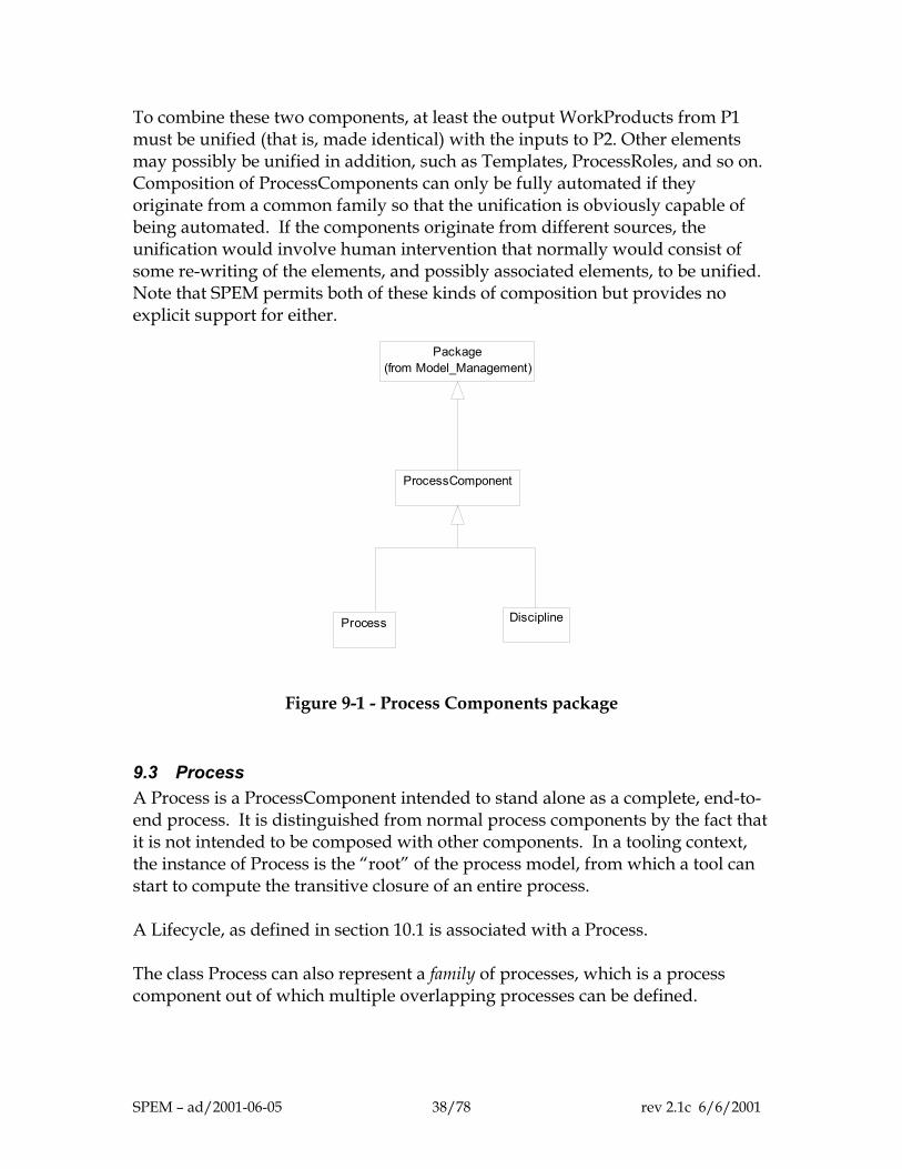
9 Process Components Figure 9-1 details the Process Components package. The classes in this package are concerned with dividing one or more process descriptions into self-contained parts that can be placed under configuration management and version control.
9.1 Package Just as in UML, a Package is a container that can both own and import process definition elements. Activities and WorkDefinitions are owned, respectively, by ProcessRoles and ProcessPerformers; other SPEM ModelElements can be owned by Packages. Packages and the Categorizes dependency can be used to implement general categorization of process description elements. A Package is created to represent each category, and all of the elements linked via a Categorizes dependency into that Package to represent membership of the category. Multiple overlapping categories can be created to serve various purposes in process engineering. A more specific kind of categorization of Activities is implemented by Discipline, see section 9.4.
9.2 ProcessComponent A ProcessComponent is a chunk of process description that is internally consistent and may be reused with other ProcessComponents to assemble a complete process. A ProcessComponent imports a non-arbitrary set of process definition elements, modeled in SPEM by ModelElements. Such a set must be self-contained; this means that there are no RefersTo dependencies from within the component to elements not within the component. It must be internally consistent in the sense that the multiplicities and constraints defined for the metamodel as a whole must be satisfied within the scope of the component.
Example
Composition of ProcessComponents is done by a process of unification. For example, consider both of these:
• a ProcessComponent P1 that takes a set of high-level use cases and non-functional requirements as input and delivers an architecture as output
• a ProcessComponent P2 that takes an architecture and a set of detailed use cases as input, and delivers an executable, unit-tested body of code as output
SPEM – ad/2001-06-05 37/78 rev 2.1c 6/6/2001
To combine these two components, at least the output WorkProducts from P1 must be unified (that is, made identical) with the inputs to P2. Other elements may possibly be unified in addition, such as Templates, ProcessRoles, and so on. Composition of ProcessComponents can only be fully automated if they originate from a common family so that the unification is obviously capable of being automated. If the components originate from different sources, the unification would involve human intervention that normally would consist of some re-writing of the elements, and possibly associated elements, to be unified. Note that SPEM permits both of these kinds of composition but provides no explicit support for either.
Package(from Model_Management)
ProcessComponent
Process Discipline
Figure 9-1 - Process Components package
9.3 Process A Process is a ProcessComponent intended to stand alone as a complete, end-to-end process. It is distinguished from normal process components by the fact that it is not intended to be composed with other components. In a tooling context, the instance of Process is the “root” of the process model, from which a tool can start to compute the transitive closure of an entire process. A Lifecycle, as defined in section 10.1 is associated with a Process. The class Process can also represent a family of processes, which is a process component out of which multiple overlapping processes can be defined.
SPEM – ad/2001-06-05 38/78 rev 2.1c 6/6/2001
9.4 Discipline A Discipline is a particular specialization of Package that partitions the Activities within a process according to a common “theme”. Partitioning the Activities in this way implies that the associated Guidance and output WorkProducts are similarly categorized under the theme. The inclusion of an Activity in a Discipline is represented by the Categorizes dependency, with the additional constraint that every Activity is categorized by exactly one Discipline.
Example
Nine disciplines are described in the Rational Unified Process 2001: Business Modeling, Requirement Management, Analysis & Design, Implementation, Test, Deployment, Project Management, Configuration and Change Management, and Environment. The Fujitsu SDEM21 development process defines 7 disciplines: Business System, Business System Specification, Application, Infrastructure, Operation and Migration, Development Support and Project Management.
Synonyms
The IBM processes use the term ‘domain’; the Rational Unified Process uses ‘core workflow’; the Fujitsu SDEM21 uses 'category'; Objectory used ‘process component’; Fusion uses the term ‘phase’, OPEN uses the work ‘activity’.
9.5 Well-formedness rules
ProcessComponent A process component must be self-contained, i.e. there are no links (associations or dependencies) to anything outside the component. [1] No dependencies outside the component. context ProcessComponent inv: let includedElements : Set(ModelElement) =
self.clientDependency->select (d | d.oclIsKindOf(Import)).supplier in
includedElements->forall ( e |
e.clientDependency.supplier->forall ( m | includedElements->includes(m))) and
includedElements->forall ( e | e.supplierDependency.client->forall ( m |
includedElements->includes(m)))
[2] No associations outside the component. context ProcessComponent inv: let includedElements : Set(ModelElement) =
SPEM – ad/2001-06-05 39/78 rev 2.1c 6/6/2001
self.clientDependency->select (d | d.oclIsKindOf(Import)).supplier in
includedElements->forall ( e |
e.allAssociatedInstances-> forall ( i | includedElements -> includes(i))
where allAssociatedInstances cannot easily be defined in OCL, but could be defined by slightly extending OCL as follows: i.allAssociatedInstances =
i.type.associationEnds->collect(ae | i.navigate(ae))
Process No additional rules.
Discipline [1] Disciplines only categorize Activities. context Discipline inv:
self.clientDependency->select(d | d.oclIsKindOf(Categorizes)).supplier->forall(m |
m.oclIsKindOf(Activity))
SPEM – ad/2001-06-05 40/78 rev 2.1c 6/6/2001
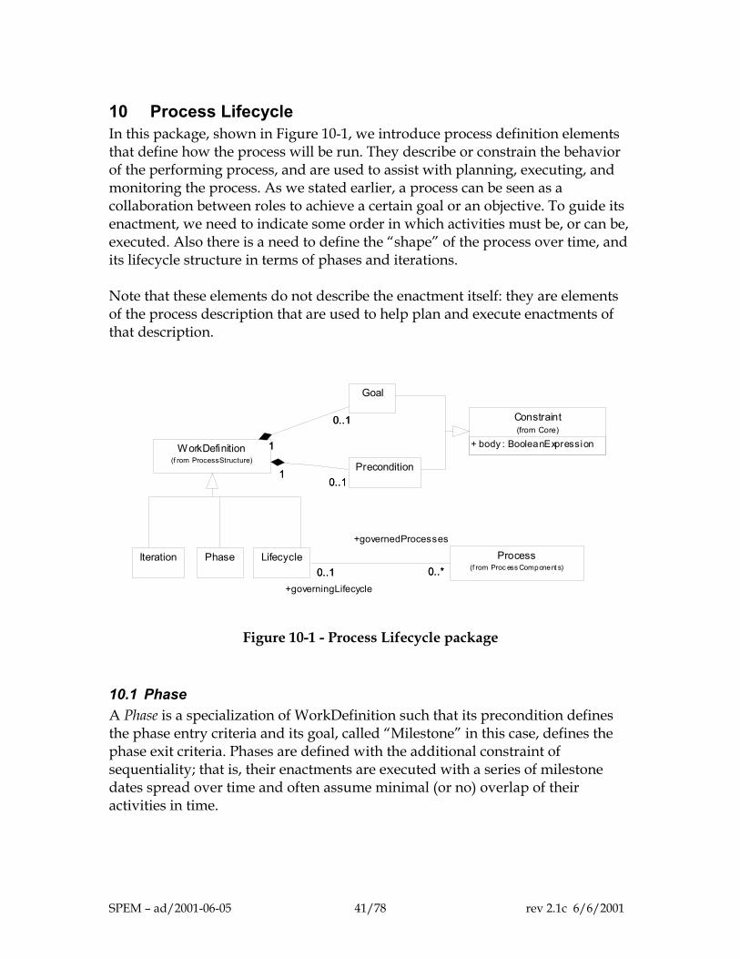
10 Process Lifecycle In this package, shown in Figure 10-1, we introduce process definition elements that define how the process will be run. They describe or constrain the behavior of the performing process, and are used to assist with planning, executing, and monitoring the process. As we stated earlier, a process can be seen as a collaboration between roles to achieve a certain goal or an objective. To guide its enactment, we need to indicate some order in which activities must be, or can be, executed. Also there is a need to define the “shape” of the process over time, and its lifecycle structure in terms of phases and iterations. Note that these elements do not describe the enactment itself: they are elements of the process description that are used to help plan and execute enactments of that description.
Constraint(from Core)
+ body : BooleanExpression
Goal
Precondition
WorkDefinition(f rom ProcessStructure)
0..1
1
0..1
1
0..11
0..11
Iteration Phase Process(f rom Proc ess Component s)
Lifecycle0..*0..1
+governedProcesses
0..*+governingLifecycle
0..1
Figure 10-1 - Process Lifecycle package
10.1 Phase A Phase is a specialization of WorkDefinition such that its precondition defines the phase entry criteria and its goal, called “Milestone” in this case, defines the phase exit criteria. Phases are defined with the additional constraint of sequentiality; that is, their enactments are executed with a series of milestone dates spread over time and often assume minimal (or no) overlap of their activities in time.
SPEM – ad/2001-06-05 41/78 rev 2.1c 6/6/2001
Examples
The Rational Unified Process (RUP) defines four sequential phases: Inception, Elaboration, Construction, and Transition. The RUP defines a phase as consisting of a certain number of iterations, which are workflows with minor milestones. The DMR Macroscope system delivery process describes five phases: Opportunity Evaluation, Preliminary Analysis, System Architecture, Release Design and Construction, and Implementation. OOSP has four phases: Initiate, Construct, Deliver, and Maintain & Support [15].
10.2 Lifecycle A process Lifecycle is defined as a sequence of Phases that achieve a specific goal. It defines the behavior of a complete process to be enacted in a given project or program.
Associations
A Lifecycle is associated with a sequence of Phases by the use of the subWork association, see section 8.2. A Lifecycle is associated with one or more Processes via the governedProcesses association that associates a Lifecycle (describing the behavior of the process) with a Process (that packages up all of the descriptive material contained in the process).
Example
The DMR Macroscope describes 3 system delivery lifecycles: a Generic Development path, an Accelerated Development path, and a Package Solution Delivery path. The Fujitsu SDEM21 provides a specific lifecycle for component-based development called ComponentAA.
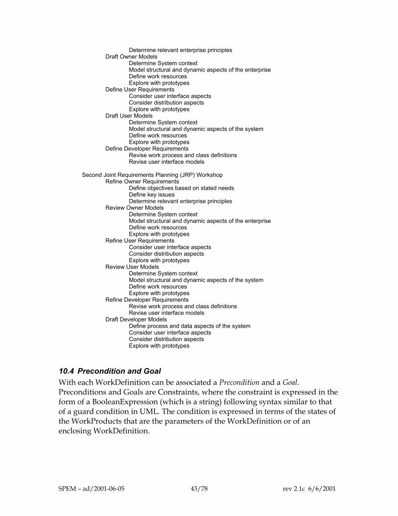
10.3 Iteration An Iteration is a composite WorkDefinition with a minor milestone.
Example
The following example work breakdown structure showing Iterations is from the DMR Macroscope: Phase
Iteration Activity
Step Preliminary Analysis First Joint Requirements Planning (JRP) Workshop Define Owner Requirements Define objectives based on stated needs Define key issues
SPEM – ad/2001-06-05 42/78 rev 2.1c 6/6/2001
Determine relevant enterprise principles Draft Owner Models Determine System context Model structural and dynamic aspects of the enterprise Define work resources Explore with prototypes Define User Requirements Consider user interface aspects Consider distribution aspects Explore with prototypes Draft User Models Determine System context Model structural and dynamic aspects of the system Define work resources Explore with prototypes Define Developer Requirements Revise work process and class definitions Revise user interface models Second Joint Requirements Planning (JRP) Workshop Refine Owner Requirements Define objectives based on stated needs Define key issues Determine relevant enterprise principles Review Owner Models Determine System context Model structural and dynamic aspects of the enterprise Define work resources Explore with prototypes Refine User Requirements Consider user interface aspects Consider distribution aspects Explore with prototypes Review User Models Determine System context Model structural and dynamic aspects of the system Define work resources Explore with prototypes Refine Developer Requirements Revise work process and class definitions Revise user interface models Draft Developer Models Define process and data aspects of the system Consider user interface aspects Consider distribution aspects Explore with prototypes
10.4 Precondition and Goal With each WorkDefinition can be associated a Precondition and a Goal. Preconditions and Goals are Constraints, where the constraint is expressed in the form of a BooleanExpression (which is a string) following syntax similar to that of a guard condition in UML. The condition is expressed in terms of the states of the WorkProducts that are the parameters of the WorkDefinition or of an enclosing WorkDefinition.
SPEM – ad/2001-06-05 43/78 rev 2.1c 6/6/2001
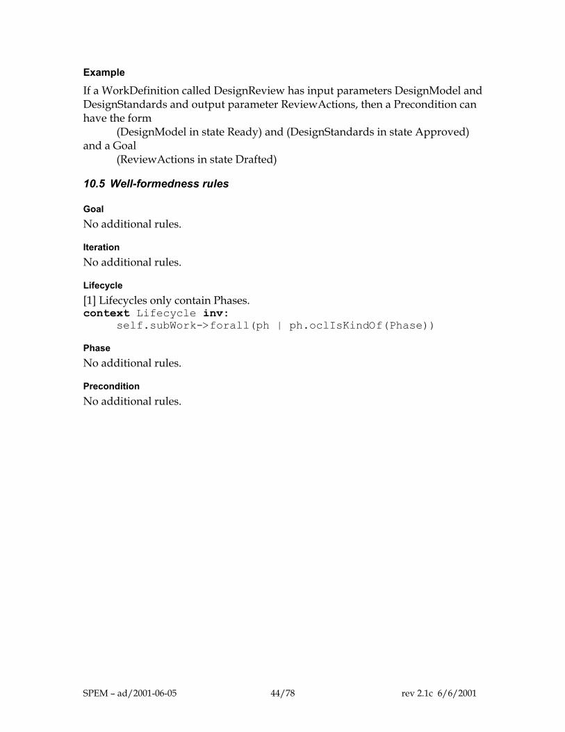
Example
If a WorkDefinition called DesignReview has input parameters DesignModel and DesignStandards and output parameter ReviewActions, then a Precondition can have the form
(DesignModel in state Ready) and (DesignStandards in state Approved) and a Goal
(ReviewActions in state Drafted)
10.5 Well-formedness rules
Goal No additional rules.
Iteration No additional rules.
Lifecycle [1] Lifecycles only contain Phases. context Lifecycle inv:
self.subWork->forall(ph | ph.oclIsKindOf(Phase))
Phase No additional rules.
Precondition No additional rules.
SPEM – ad/2001-06-05 44/78 rev 2.1c 6/6/2001
11 Management of Process Assets The management of multiple processes, variants, derivatives or versions is beyond the scope of this metamodel. As all techniques and tools used in the area of configuration management and change management for software can be applied literally to a software process product, it does not make sense to replicate these aspects in the SPEM. See standards IEEE 610.12-1990 or ISO 12207. All SPEM Elements (modeled as ModelElements) are configuration items. As such, they can have multiple versions. The versions of a given configuration item are linked to each other to form histories. Variants can be introduced by creating parallel histories. A specific process configuration is formed by selecting one version, at the most, for each SPEM Element. If a process definition element is required in two forms within a single process configuration, it must be cloned and given a specific identity; for example, “simple design review” versus a “complex and critical review”. Process variants are defined similarly by selecting Process Definition Elements from a consistent set of version histories all belonging to the same variant.
SPEM – ad/2001-06-05 45/78 rev 2.1c 6/6/2001
12 SPEM as a UML Profile In the chapters so far, SPEM has been directly defined as a metamodel. SPEM can be used by directly instantiating this stand-alone metamodel. But SPEM is also defined as a UML Profile. SPEM is dedicated to software processes modeling. Many features of the UML provide the necessary basis for modeling processes, and many other UML features provide useful additional modeling capacities. Being a UML profile, SPEM both defines modeling capacities dedicated to the software process domain, and gains the benefit of the expressiveness of UML. For example, Use Case modeling, which is sometimes used for modeling processes, is not defined as a specific SPEM facility, but can be inherited from UML. Alignment with various process modeling languages is another advantage of using UML Profiles. The SPEM profile uses extensively the UML Activity Diagram model to give more detail to the work decomposition that is represented in the stand-alone metamodel by the WorkDefinition::subWork association. It is expected that the various kind of process modeling techniques (Business Process Modeling, Workflow, etc.) will be aligned with UML at some time. SPEM will naturally benefit from this convergence, and from any other convergence and improvements that will occur with UML. Finally, a wide community of software developers is familiar with UML and uses a UML case tool environment. Defining a UML profile allows this important community to reuse its modeling knowledge and tools in the software-process modeling domain. The UML 1.4 definition of profile is given in section 1.5 of this document, and is repeated here:
A profile stereotype of Package contains one or more related extensions of standard UML semantics (refer to Section 2.6, “Extension Mechanisms”). These are normally intended to customize UML for a particular domain or purpose. Profiles can contain stereotypes, tag definitions, and constraints. They can also contain data types that are used by tag definitions for informally declaring the types of the values that can be associated with tag definitions. In addition, a profile package can specify a related model library and identify a subset of the UML metamodel that is applicable for the profile. In principle, profiles merely refine the standard semantics of UML by adding further
SPEM – ad/2001-06-05 46/78 rev 2.1c 6/6/2001

constraints and interpretations that capture domain-specific semantics and modeling patterns. They do not add any new fundamental concepts.
In order to define a UML profile for SPEM, the following must be done.
1. Identify that subset of the UML metamodel classes to be included in the profile.
2. For most classes in the SPEM metamodel, identify a “base class” in the
UML metamodel subset that will, when stereotyped appropriately, act in place of the SPEM class. The technique used here is specified in section 3.35.2 of the UML 1.4 specification. The fact that SPEM is itself defined as an extension of a subset of UML makes this very straightforward. For the one class (GuidanceKind) in the SPEM metamodel to which the base class technique does not apply, the semantics of instances of that class are emulated using UML stereotypes.
3. For each attribute and association in the SPEM metamodel, define a way
to emulate that attribute or association. In the SPEM profile, attributes are emulated by means of TaggedValues. Most associations have close analogues in the UML metamodel. Those that don’t, get special treatment as detailed below.
4. For those parts of the UML subset that have a plausible mapping into
SPEM concepts, but are not used directly to emulate the SPEM metamodel, show how they are mapped into SPEM-related concepts. For SPEM, this applies particularly to the use of Use Case diagrams, Activity diagrams and state machines.
5. Give additional constraints over the UML metamodel that are implied by
the use of the profile.
6. Define notational icons for SPEM concepts that are represented by UML stereotypes.
The remaining parts of this chapter deal with each of these topics.
12.1 Identified subset of the UML Metamodel The SPEM profile retains the following packages from the UML Metamodel:
Core
SPEM – ad/2001-06-05 47/78 rev 2.1c 6/6/2001
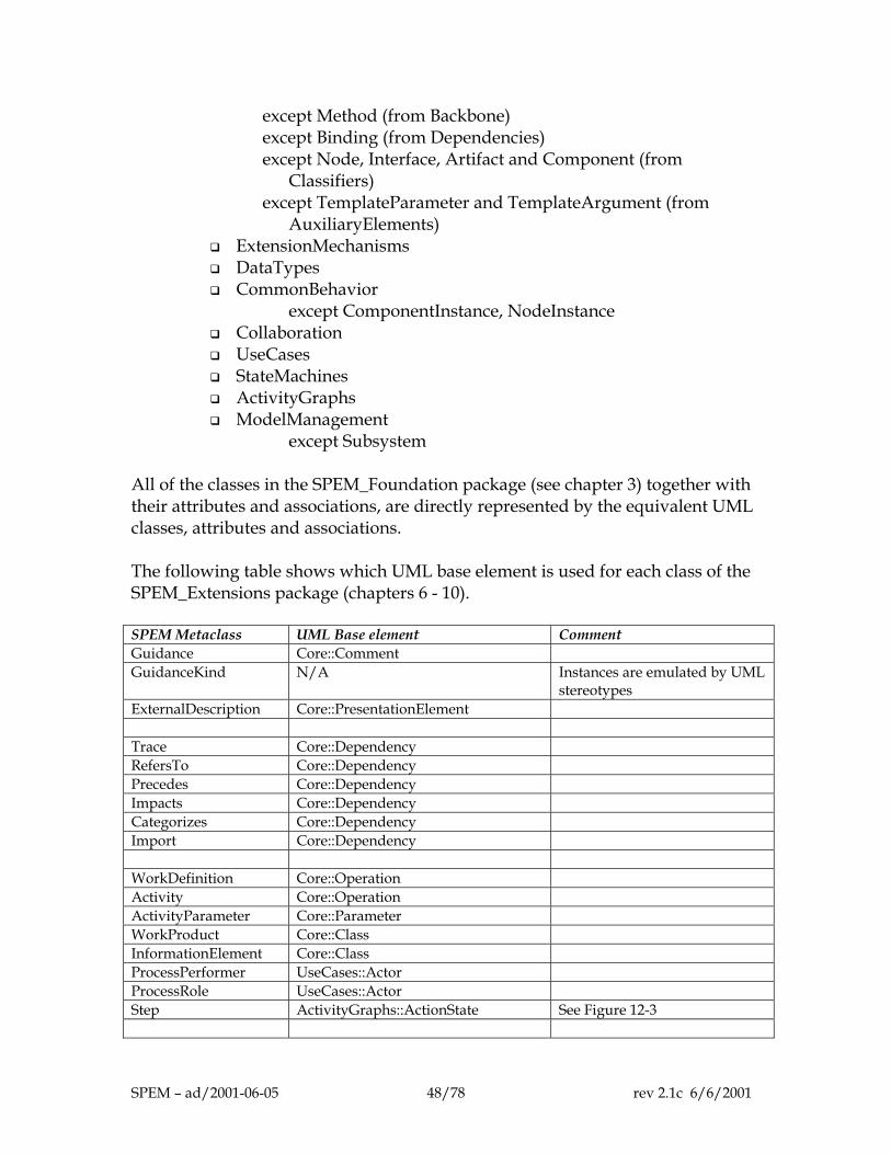
except Method (from Backbone) except Binding (from Dependencies) except Node, Interface, Artifact and Component (from
Classifiers) except TemplateParameter and TemplateArgument (from
AuxiliaryElements) ExtensionMechanisms DataTypes CommonBehavior
except ComponentInstance, NodeInstance Collaboration UseCases StateMachines ActivityGraphs ModelManagement
except Subsystem All of the classes in the SPEM_Foundation package (see chapter 3) together with their attributes and associations, are directly represented by the equivalent UML classes, attributes and associations. The following table shows which UML base element is used for each class of the SPEM_Extensions package (chapters 6 - 10). SPEM Metaclass UML Base element Comment Guidance Core::Comment GuidanceKind N/A Instances are emulated by UML
stereotypes ExternalDescription Core::PresentationElement Trace Core::Dependency RefersTo Core::Dependency Precedes Core::Dependency Impacts Core::Dependency Categorizes Core::Dependency Import Core::Dependency WorkDefinition Core::Operation Activity Core::Operation ActivityParameter Core::Parameter WorkProduct Core::Class InformationElement Core::Class ProcessPerformer UseCases::Actor ProcessRole UseCases::Actor Step ActivityGraphs::ActionState See Figure 12-3
SPEM – ad/2001-06-05 48/78 rev 2.1c 6/6/2001
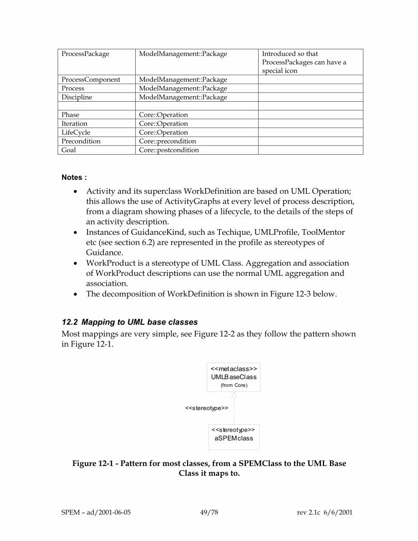
ProcessPackage ModelManagement::Package Introduced so that ProcessPackages can have a special icon
ProcessComponent ModelManagement::Package Process ModelManagement::Package Discipline ModelManagement::Package Phase Core::Operation Iteration Core::Operation LifeCycle Core::Operation Precondition Core::precondition Goal Core::postcondition
Notes :
• Activity and its superclass WorkDefinition are based on UML Operation; this allows the use of ActivityGraphs at every level of process description, from a diagram showing phases of a lifecycle, to the details of the steps of an activity description.
• Instances of GuidanceKind, such as Techique, UMLProfile, ToolMentor etc (see section 6.2) are represented in the profile as stereotypes of Guidance.
• WorkProduct is a stereotype of UML Class. Aggregation and association of WorkProduct descriptions can use the normal UML aggregation and association.
• The decomposition of WorkDefinition is shown in Figure 12-3 below.
12.2 Mapping to UML base classes Most mappings are very simple, see Figure 12-2 as they follow the pattern shown in Figure 12-1.
aSPEMclass<<stereotype>>
UMLBaseClass(from Core)
<<metaclass>>
<<stereotype>>
Figure 12-1 - Pattern for most classes, from a SPEMClass to the UML Base
Class it maps to.
SPEM – ad/2001-06-05 49/78 rev 2.1c 6/6/2001
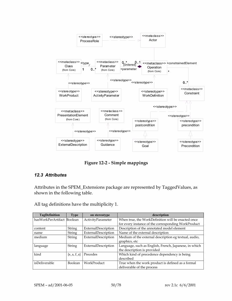
WorkDefinition<<stereotype>>
WorkProduct<<stereotype>>
Act ivityParameter<<stereotype>>
precondition<<stereotype>>
postcondit ion<<stereotype>>
Precondition<<stereotype>>
Goal<<stereotype>>
ProcessRole<<stereotype>>
Class(from Core)
<<metaclass>>
<<stereotype>>
Parameter(from Core)
<<metaclass>>
<<stereotype>>
0..*1 0..*
+type
1/
Constraint<<metaclass>>
<<stereotype>>
Operation(from Core)
<<metaclass>>
<<stereotype>>
0..* 0..1
+parameter
0..* 0..1{ordered}
*
0..*
+constrainedElement
*
0..*
Actor<<metaclass>><<stereotype>>
Guidance<<stereotype>>
ExternalDescription<<stereotype>>
Comment(from Core)
<<metaclass >><<stereotype>>
<<stereotype>>
PresentationElement(f rom Core )
<<metaclass>>
<<stereotype>>
Figure 12-2 - Simple mappings
12.3 Attributes Attributes in the SPEM_Extensions package are represented by TaggedValues, as shown in the following table. All tag definitions have the multiplicity 1.
TagDefinition Type on stereotype description hasWorkPerArtifact Boolean ActivityParameter When true, the WorkDefinition will be enacted once
for every instance of the corresponding WorkProduct content String ExternalDescription Description of the annotated model element name String ExternalDescription Name of the external description medium String ExternalDescription Medium of the external description eg textual, audio,
graphics, etc language String ExternalDescription Language, such as English, French, Japanese, in which
the description is provided kind {s_s, f_s} Precedes Which kind of precedence dependency is being
described isDeliverable Boolean WorkProduct True when the work product is defined as a formal
deliverable of the process
SPEM – ad/2001-06-05 50/78 rev 2.1c 6/6/2001
12.4 Associations Associations in the SPEM_Extensions package are represented in a variety of ways, as follows. Guidance::kind. This is not required, because instances of GuidanceKind are represented as stereotypes of Guidance. Guidance::annotatedElement. This is represented by the UML association Comment::annotatedElement. ActivityParameter::type. This is represented by the UML association Parameter::type. WorkDefinition::owner. This is represented by the UML association Feature::owner. WorkDefinition::subWork. This is not represented directly. Instead it is represented using ActivityGraphs, as shown in Figure 12-3. In green (dark) are the UML base classes that together correspond to the subWork association: ActivityGraph, CompositeState, ActionState, CallAction. Activity::steps. This is also represented by ActivityGraphs, as shown in Figure 12-3. WorkDefinition::goal and WorkDefinition::precondition. These are represented by the UML association ModelElement::constraint. Process::governingLifecycle. This is represented by a new stereotype of Abstraction called «governs», which acts between a Lifecycle and the processes that it is related to.
SPEM – ad/2001-06-05 51/78 rev 2.1c 6/6/2001
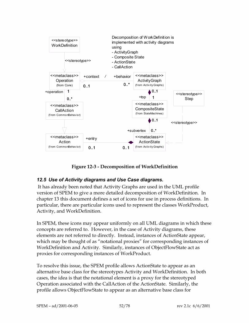
WorkDefinition<<stereotype>>
Decomposit ion of WorkDefinit ion is implemented with ac tivity diagrams using - ActivityGraph - Composite State - ActionState - CallAction
Step<<stereotype>>
CallAction(f rom CommonBehav ior)
<<metaclass>>
Operation(from Core)
<<metaclass>>
1
0..*
+operation 1
0..*
<<stereotype>>
Action(f rom CommonBehav ior)
<<metaclass>>
ActivityGraph(f rom Activ ity Graphs)
<<metaclass>>
0..*0..1
+behavior
0..*
+context
0..1
/
ActionState(f rom Activ ity Graphs)
<<metaclass>>
0..1 0..1
+entry
0..1 0..1
CompositeState(f rom StateMachines)
<<metaclass>>10..1
+top 10..1
0..*
0..1
+subvertex 0..*
0..1 <<stereotype>>
Figure 12-3 - Decomposition of WorkDefinition
12.5 Use of Activity diagrams and Use Case diagrams. It has already been noted that Activity Graphs are used in the UML profile version of SPEM to give a more detailed decomposition of WorkDefinition. In chapter 13 this document defines a set of icons for use in process definitions. In particular, there are particular icons used to represent the classes WorkProduct, Activity, and WorkDefinition. In SPEM, these icons may appear uniformly on all UML diagrams in which these concepts are referred to. However, in the case of Activity diagrams, these elements are not referred to directly. Instead, instances of ActionState appear, which may be thought of as “notational proxies” for corresponding instances of WorkDefinition and Activity. Similarly, instances of ObjectFlowState act as proxies for corresponding instances of WorkProduct. To resolve this issue, the SPEM profile allows ActionState to appear as an alternative base class for the stereotypes Activity and WorkDefinition. In both cases, the idea is that the notational element is a proxy for the stereotyped Operation associated with the CallAction of the ActionState. Similarly, the profile allows ObjectFlowState to appear as an alternative base class for
SPEM – ad/2001-06-05 52/78 rev 2.1c 6/6/2001
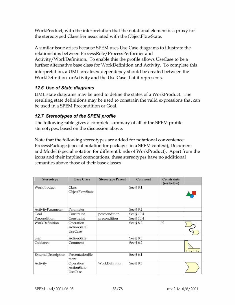
WorkProduct, with the interpretation that the notational element is a proxy for the stereotyped Classifier associated with the ObjectFlowState. A similar issue arises because SPEM uses Use Case diagrams to illustrate the relationships between ProcessRole/ProcessPerformer and Activity/WorkDefinition. To enable this the profile allows UseCase to be a further alternative base class for WorkDefinition and Activity. To complete this interpretation, a UML «realize» dependency should be created between the WorkDefinition orActivity and the Use Case that it represents.
12.6 Use of State diagrams UML state diagrams may be used to define the states of a WorkProduct. The resulting state definitions may be used to constrain the valid expressions that can be used in a SPEM Precondition or Goal.
12.7 Stereotypes of the SPEM profile The following table gives a complete summary of all of the SPEM profile stereotypes, based on the discussion above. Note that the following stereotypes are added for notational convenience: ProcessPackage (special notation for packages in a SPEM context), Document and Model (special notation for different kinds of WorkProduct). Apart from the icons and their implied connotations, these stereotypes have no additional semantics above those of their base classes.
Stereotype Base Class Stereotype Parent Comment Constraints (see below)
Notation(chapter 13)
WorkProduct Class ObjectFlowState
See § 8.1
ActivityParameter Parameter See § 8.2 Goal Constraint postcondition See § 10.4 Precondition Constraint precondition See § 10.4 WorkDefinition Operation
ActionState UseCase
See § 8.2 P2
Step ActionState See § 8.3 Guidance Comment See § 6.2
ExternalDescription PresentationEle
ment See § 6.1
Activity Operation ActionState UseCase
WorkDefinition See § 8.3
SPEM – ad/2001-06-05 53/78 rev 2.1c 6/6/2001
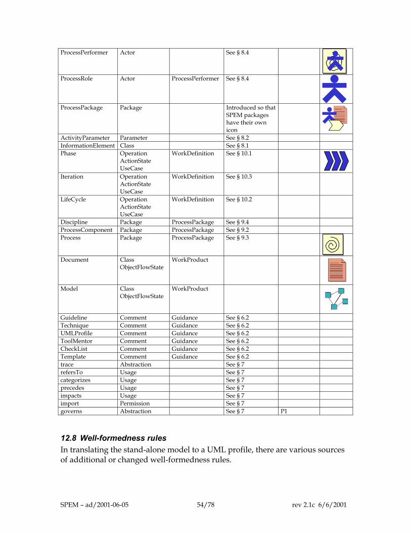
ProcessPerformer Actor See § 8.4
ProcessRole Actor ProcessPerformer See § 8.4
ProcessPackage Package Introduced so that
SPEM packages have their own icon
ActivityParameter Parameter See § 8.2 InformationElement Class See § 8.1 Phase Operation
ActionState UseCase
WorkDefinition See § 10.1
Iteration Operation
ActionState UseCase
WorkDefinition See § 10.3
LifeCycle Operation ActionState UseCase
WorkDefinition See § 10.2
Discipline Package ProcessPackage See § 9.4 ProcessComponent Package ProcessPackage See § 9.2 Process Package ProcessPackage See § 9.3
Document Class
ObjectFlowState WorkProduct
Model Class
ObjectFlowState WorkProduct
Guideline Comment Guidance See § 6.2 Technique Comment Guidance See § 6.2 UMLProfile Comment Guidance See § 6.2 ToolMentor Comment Guidance See § 6.2 CheckList Comment Guidance See § 6.2 Template Comment Guidance See § 6.2 trace Abstraction See § 7 refersTo Usage See § 7 categorizes Usage See § 7 precedes Usage See § 7 impacts Usage See § 7 import Permission See § 7 governs Abstraction See § 7 P1
12.8 Well-formedness rules In translating the stand-alone model to a UML profile, there are various sources of additional or changed well-formedness rules.
SPEM – ad/2001-06-05 54/78 rev 2.1c 6/6/2001
Restricted multiplicities
As pointed out in chapter 3, the stand-alone SPEM metamodel is based on a subset of UML with some restrictions on the multiplicities. These restrictions also apply to the UML profile.
Use of context and oclIsKindOf
In the presence of stereotypes, the use of oclIsKindOf needs in principle to be modified. We assume that the meaning of oclIsKindOf can be extended in the presence of stereotypes, so that if oclIsKindOf refers to a stereotype name, it delivers true if the tested element has that stereotype or a sub-stereotype. Similarly, constraints on stereotypes are written under the assumption that it is valid to use a stereotype name in the context part of the constraint. Strictly-speaking this is a shorthand, for example: context ProcessPackage inv: X can be considered as a shorthand for context Package inv: (self.stereotype.name = “ProcessComponent” or self.stereotype.name = “Process” or self.stereotype.name = “Discipline”) implies X With these provisos, all of the well-formedness rules in earlier chapters apply to the profile.
Profile-specific rules
The following rules apply to the construction of the profile itself.
governs [P1] A governs dependency acts between a Lifecycle and a ProcessPerformer context Dependency inv: self.stereotype.name = “governs” implies self.supplier->exists(stereotype.name=“Lifecycle”)
and self.client->exists(stereotype.name=”ProcessPerformer”) WorkDefinition [P2] A WorkDefinition behavior is defined using no more than a single Activity Graph and in no other way.
SPEM – ad/2001-06-05 55/78 rev 2.1c 6/6/2001
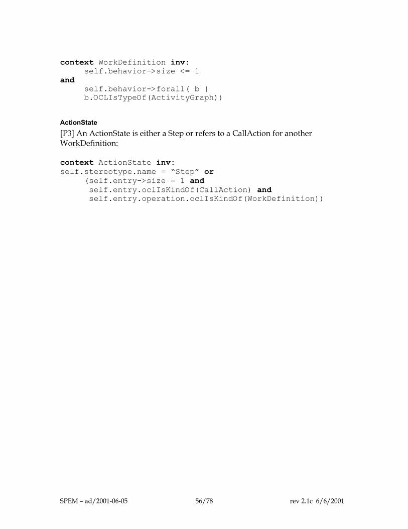
context WorkDefinition inv:
self.behavior->size <= 1 and
self.behavior->forall( b | b.OCLIsTypeOf(ActivityGraph))
ActionState [P3] An ActionState is either a Step or refers to a CallAction for another WorkDefinition: context ActionState inv: self.stereotype.name = “Step” or
(self.entry->size = 1 and self.entry.oclIsKindOf(CallAction) and self.entry.operation.oclIsKindOf(WorkDefinition))
SPEM – ad/2001-06-05 56/78 rev 2.1c 6/6/2001
13 Notation
13.1 Diagrams Basic UML diagrams can be used to present different perspectives of a software process model. In particular, the following UML notations are useful: Class diagram Package diagram Activity diagram Use case diagram Sequence diagram Statechart diagram
Because some semantic elements of UML have been excluded from SPEM, the following notations should not be used: implementation diagrams component or node diagrams.
There are some notation and diagrams that are not excluded, but for which we have not specified any mapping nor meaning.
13.2 Suggested icons Column "Notation" in table "Stereotypes" in section 12.7 suggests alternate representations for most frequently used concrete classes of the metamodel. These icons can be used in modeling a software development process to represent activities, work products, process roles, etc. It is suggested to replace the regular symbol with these icons as shown in the examples below.
13.3 Class diagram
Class diagrams allow the representation of the following aspects of a software process: Inheritance Dependencies Simple associations Comments to point to the guidance (for example URL link) Relations between ProcessPerformer or ProcessRole and WorkProduct Structure, decomposition and dependencies of WorkProducts (see example in
Figure 13-1)
SPEM – ad/2001-06-05 57/78 rev 2.1c 6/6/2001
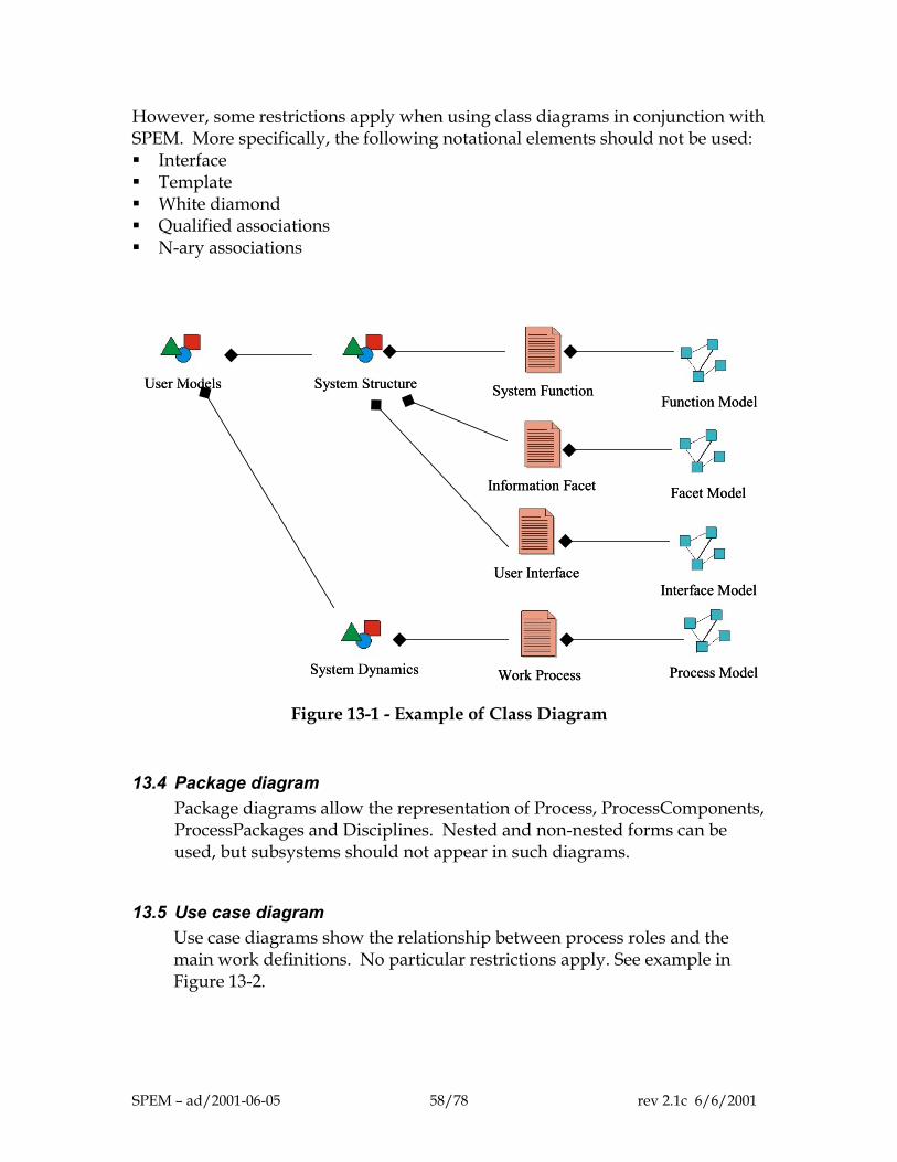
However, some restrictions apply when using class diagrams in conjunction with SPEM. More specifically, the following notational elements should not be used: Interface Template White diamond Qualified associations N-ary associations
User ModelsUser Models System StructureSystem Structure
System DynamicsSystem Dynamics
System FunctionSystem Function
Information FacetInformation Facet
User InterfaceUser Interface
Function ModelFunction Model
Facet ModelFacet Model
Interface ModelInterface Model
Work ProcessWork Process Process ModelProcess Model
Figure 13-1 - Example of Class Diagram
13.4 Package diagram Package diagrams allow the representation of Process, ProcessComponents, ProcessPackages and Disciplines. Nested and non-nested forms can be used, but subsystems should not appear in such diagrams.
13.5 Use case diagram Use case diagrams show the relationship between process roles and the main work definitions. No particular restrictions apply. See example in Figure 13-2.
SPEM – ad/2001-06-05 58/78 rev 2.1c 6/6/2001
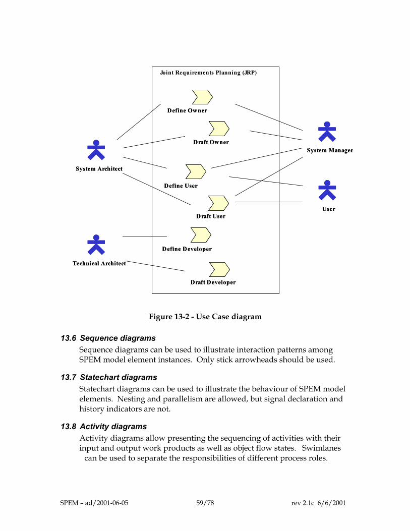
1
1
1
S
Joint Requirements Planning (JRP)
Define Owner Define Owner
Draft Owner Draft Owner
Define User Define User
Draft User Draft User
Define Developer Define Developer
Draft Developer Draft Developer
System Architect System Architect
System ManagerSystem Manager
UserUser
Technical Architect Technical Architect
Figure 13-2 - Use Case diagram
3.6 Sequence diagrams Sequence diagrams can be used to illustrate interaction patterns among SPEM model element instances. Only stick arrowheads should be used.
3.7 Statechart diagrams Statechart diagrams can be used to illustrate the behaviour of SPEM model elements. Nesting and parallelism are allowed, but signal declaration and history indicators are not.
3.8 Activity diagrams Activity diagrams allow presenting the sequencing of activities with their input and output work products as well as object flow states. Swimlanes
can be used to separate the responsibilities of different process roles.
PEM – ad/2001-06-05 59/78 rev 2.1c 6/6/2001
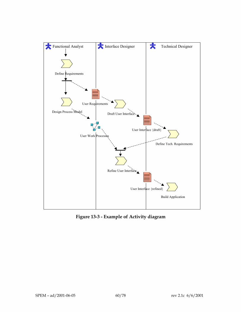
Functional Analyst Interface Designer Technical Designer
Define Requirements
User Requirements
Draft User InterfaceDesign Process Model
User Work Processes
User Interface {draft}
Define Tech. Requirements
Refine User Interface
User Interface {refined}
Build Application
Figure 13-3 - Example of Activity diagram
SPEM – ad/2001-06-05 60/78 rev 2.1c 6/6/2001
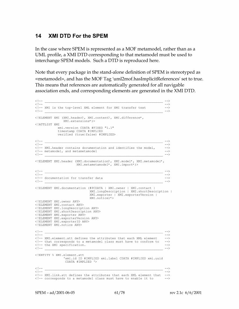
14 XMI DTD For the SPEM In the case where SPEM is represented as a MOF metamodel, rather than as a UML profile, a XMI DTD corresponding to that metamodel must be used to interchange SPEM models. Such a DTD is reproduced here. Note that every package in the stand-alone definition of SPEM is stereotyped as «metamodel», and has the MOF Tag 'uml2mof.hasImplicitReferences' set to true. This means that references are automatically generated for all navigable association ends, and corresponding elements are generated in the XMI DTD. <!-- _______________________________________________________________ --> <!-- --> <!-- XMI is the top-level XML element for XMI transfer text --> <!-- _______________________________________________________________ --> <!ELEMENT XMI (XMI.header?, XMI.content?, XMI.difference*, XMI.extensions*)> <!ATTLIST XMI xmi.version CDATA #FIXED "1.1" timestamp CDATA #IMPLIED verified (true|false) #IMPLIED> <!-- _______________________________________________________________ --> <!-- --> <!-- XMI.header contains documentation and identifies the model, --> <!-- metamodel, and metametamodel --> <!-- _______________________________________________________________ --> <!ELEMENT XMI.header (XMI.documentation?, XMI.model*, XMI.metamodel*, XMI.metametamodel*, XMI.import*)> <!-- _______________________________________________________________ --> <!-- --> <!-- documentation for transfer data --> <!-- _______________________________________________________________ --> <!ELEMENT XMI.documentation (#PCDATA | XMI.owner | XMI.contact | XMI.longDescription | XMI.shortDescription | XMI.exporter | XMI.exporterVersion | XMI.notice)*> <!ELEMENT XMI.owner ANY> <!ELEMENT XMI.contact ANY> <!ELEMENT XMI.longDescription ANY> <!ELEMENT XMI.shortDescription ANY> <!ELEMENT XMI.exporter ANY> <!ELEMENT XMI.exporterVersion ANY> <!ELEMENT XMI.exporterID ANY> <!ELEMENT XMI.notice ANY> <!-- _______________________________________________________________ --> <!-- --> <!-- XMI.element.att defines the attributes that each XML element --> <!-- that corresponds to a metamodel class must have to conform to --> <!-- the XMI specification. --> <!-- _______________________________________________________________ --> <!ENTITY % XMI.element.att 'xmi.id ID #IMPLIED xmi.label CDATA #IMPLIED xmi.uuid CDATA #IMPLIED '> <!-- _______________________________________________________________ --> <!-- --> <!-- XMI.link.att defines the attributes that each XML element that --> <!-- corresponds to a metamodel class must have to enable it to -->
SPEM – ad/2001-06-05 61/78 rev 2.1c 6/6/2001
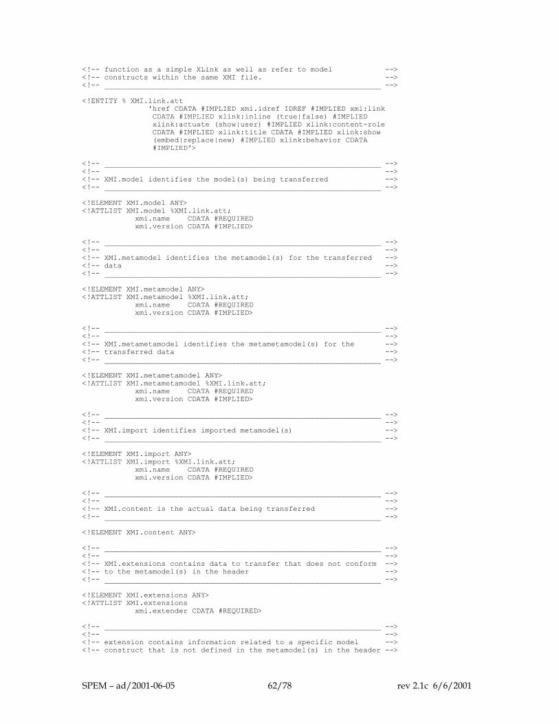
<!-- function as a simple XLink as well as refer to model --> <!-- constructs within the same XMI file. --> <!-- _______________________________________________________________ --> <!ENTITY % XMI.link.att 'href CDATA #IMPLIED xmi.idref IDREF #IMPLIED xml:link CDATA #IMPLIED xlink:inline (true|false) #IMPLIED xlink:actuate (show|user) #IMPLIED xlink:content-role CDATA #IMPLIED xlink:title CDATA #IMPLIED xlink:show (embed|replace|new) #IMPLIED xlink:behavior CDATA #IMPLIED'> <!-- _______________________________________________________________ --> <!-- --> <!-- XMI.model identifies the model(s) being transferred --> <!-- _______________________________________________________________ --> <!ELEMENT XMI.model ANY> <!ATTLIST XMI.model %XMI.link.att; xmi.name CDATA #REQUIRED xmi.version CDATA #IMPLIED> <!-- _______________________________________________________________ --> <!-- --> <!-- XMI.metamodel identifies the metamodel(s) for the transferred --> <!-- data --> <!-- _______________________________________________________________ --> <!ELEMENT XMI.metamodel ANY> <!ATTLIST XMI.metamodel %XMI.link.att; xmi.name CDATA #REQUIRED xmi.version CDATA #IMPLIED> <!-- _______________________________________________________________ --> <!-- --> <!-- XMI.metametamodel identifies the metametamodel(s) for the --> <!-- transferred data --> <!-- _______________________________________________________________ --> <!ELEMENT XMI.metametamodel ANY> <!ATTLIST XMI.metametamodel %XMI.link.att; xmi.name CDATA #REQUIRED xmi.version CDATA #IMPLIED> <!-- _______________________________________________________________ --> <!-- --> <!-- XMI.import identifies imported metamodel(s) --> <!-- _______________________________________________________________ --> <!ELEMENT XMI.import ANY> <!ATTLIST XMI.import %XMI.link.att; xmi.name CDATA #REQUIRED xmi.version CDATA #IMPLIED> <!-- _______________________________________________________________ --> <!-- --> <!-- XMI.content is the actual data being transferred --> <!-- _______________________________________________________________ --> <!ELEMENT XMI.content ANY> <!-- _______________________________________________________________ --> <!-- --> <!-- XMI.extensions contains data to transfer that does not conform --> <!-- to the metamodel(s) in the header --> <!-- _______________________________________________________________ --> <!ELEMENT XMI.extensions ANY> <!ATTLIST XMI.extensions xmi.extender CDATA #REQUIRED> <!-- _______________________________________________________________ --> <!-- --> <!-- extension contains information related to a specific model --> <!-- construct that is not defined in the metamodel(s) in the header -->
SPEM – ad/2001-06-05 62/78 rev 2.1c 6/6/2001
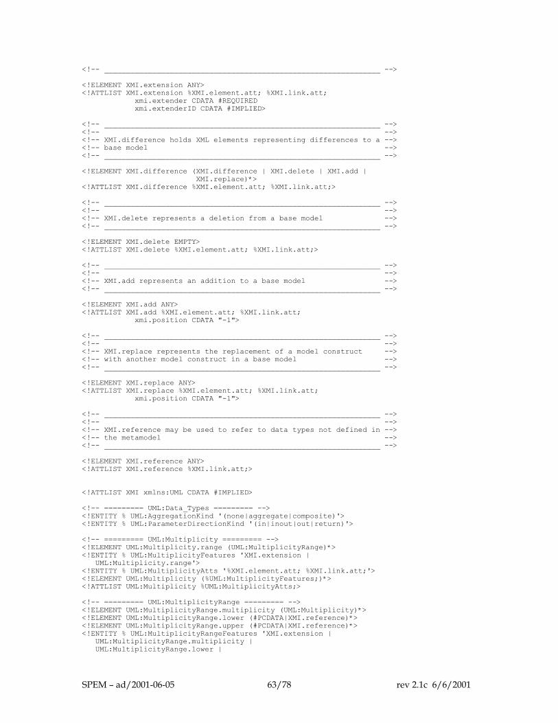
<!-- _______________________________________________________________ --> <!ELEMENT XMI.extension ANY> <!ATTLIST XMI.extension %XMI.element.att; %XMI.link.att; xmi.extender CDATA #REQUIRED xmi.extenderID CDATA #IMPLIED> <!-- _______________________________________________________________ --> <!-- --> <!-- XMI.difference holds XML elements representing differences to a --> <!-- base model --> <!-- _______________________________________________________________ --> <!ELEMENT XMI.difference (XMI.difference | XMI.delete | XMI.add | XMI.replace)*> <!ATTLIST XMI.difference %XMI.element.att; %XMI.link.att;> <!-- _______________________________________________________________ --> <!-- --> <!-- XMI.delete represents a deletion from a base model --> <!-- _______________________________________________________________ --> <!ELEMENT XMI.delete EMPTY> <!ATTLIST XMI.delete %XMI.element.att; %XMI.link.att;> <!-- _______________________________________________________________ --> <!-- --> <!-- XMI.add represents an addition to a base model --> <!-- _______________________________________________________________ --> <!ELEMENT XMI.add ANY> <!ATTLIST XMI.add %XMI.element.att; %XMI.link.att; xmi.position CDATA "-1"> <!-- _______________________________________________________________ --> <!-- --> <!-- XMI.replace represents the replacement of a model construct --> <!-- with another model construct in a base model --> <!-- _______________________________________________________________ --> <!ELEMENT XMI.replace ANY> <!ATTLIST XMI.replace %XMI.element.att; %XMI.link.att; xmi.position CDATA "-1"> <!-- _______________________________________________________________ --> <!-- --> <!-- XMI.reference may be used to refer to data types not defined in --> <!-- the metamodel --> <!-- _______________________________________________________________ --> <!ELEMENT XMI.reference ANY> <!ATTLIST XMI.reference %XMI.link.att;> <!ATTLIST XMI xmlns:UML CDATA #IMPLIED> <!-- ========= UML:Data_Types ========= --> <!ENTITY % UML:AggregationKind '(none|aggregate|composite)'> <!ENTITY % UML:ParameterDirectionKind '(in|inout|out|return)'> <!-- ========= UML:Multiplicity ========= --> <!ELEMENT UML:Multiplicity.range (UML:MultiplicityRange)*> <!ENTITY % UML:MultiplicityFeatures 'XMI.extension | UML:Multiplicity.range'> <!ENTITY % UML:MultiplicityAtts '%XMI.element.att; %XMI.link.att;'> <!ELEMENT UML:Multiplicity (%UML:MultiplicityFeatures;)*> <!ATTLIST UML:Multiplicity %UML:MultiplicityAtts;> <!-- ========= UML:MultiplicityRange ========= --> <!ELEMENT UML:MultiplicityRange.multiplicity (UML:Multiplicity)*> <!ELEMENT UML:MultiplicityRange.lower (#PCDATA|XMI.reference)*> <!ELEMENT UML:MultiplicityRange.upper (#PCDATA|XMI.reference)*> <!ENTITY % UML:MultiplicityRangeFeatures 'XMI.extension | UML:MultiplicityRange.multiplicity | UML:MultiplicityRange.lower |
SPEM – ad/2001-06-05 63/78 rev 2.1c 6/6/2001
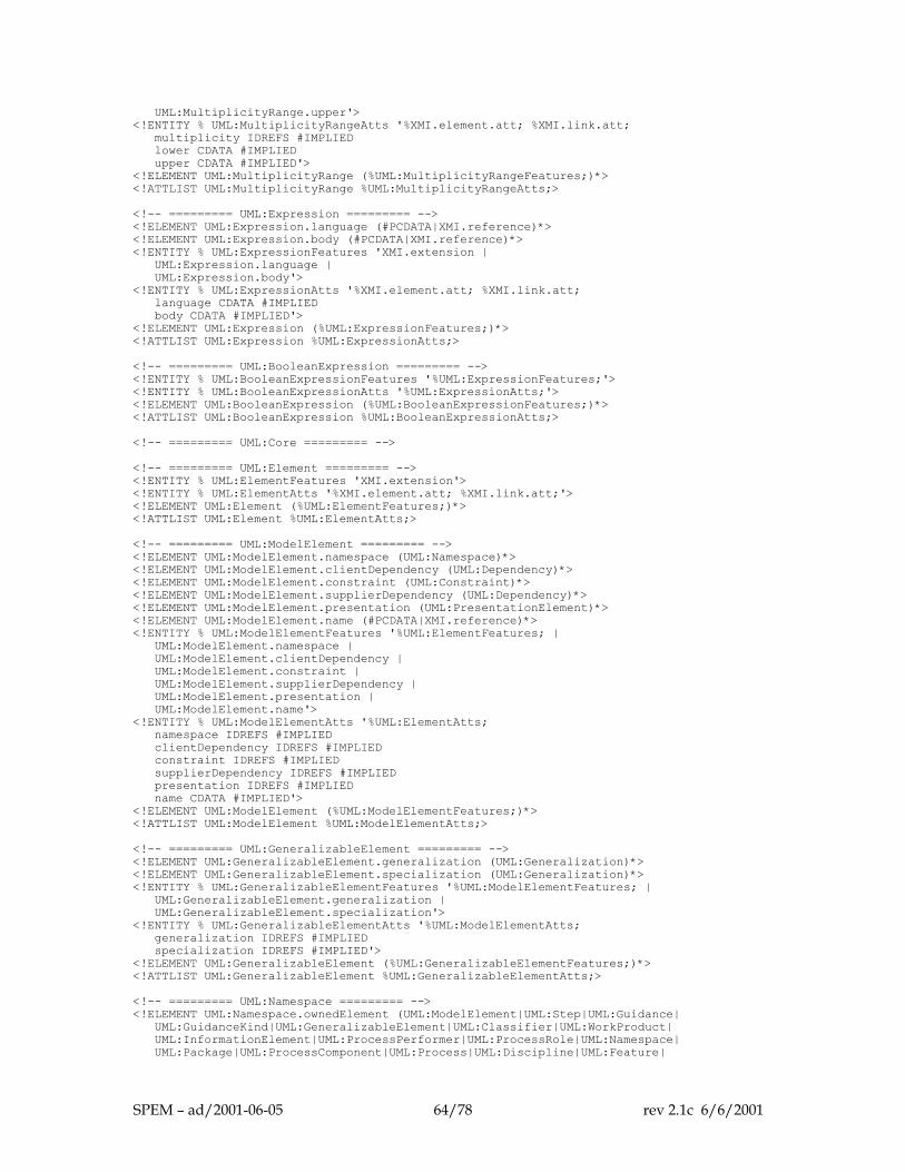
UML:MultiplicityRange.upper'> <!ENTITY % UML:MultiplicityRangeAtts '%XMI.element.att; %XMI.link.att; multiplicity IDREFS #IMPLIED lower CDATA #IMPLIED upper CDATA #IMPLIED'> <!ELEMENT UML:MultiplicityRange (%UML:MultiplicityRangeFeatures;)*> <!ATTLIST UML:MultiplicityRange %UML:MultiplicityRangeAtts;> <!-- ========= UML:Expression ========= --> <!ELEMENT UML:Expression.language (#PCDATA|XMI.reference)*> <!ELEMENT UML:Expression.body (#PCDATA|XMI.reference)*> <!ENTITY % UML:ExpressionFeatures 'XMI.extension | UML:Expression.language | UML:Expression.body'> <!ENTITY % UML:ExpressionAtts '%XMI.element.att; %XMI.link.att; language CDATA #IMPLIED body CDATA #IMPLIED'> <!ELEMENT UML:Expression (%UML:ExpressionFeatures;)*> <!ATTLIST UML:Expression %UML:ExpressionAtts;> <!-- ========= UML:BooleanExpression ========= --> <!ENTITY % UML:BooleanExpressionFeatures '%UML:ExpressionFeatures;'> <!ENTITY % UML:BooleanExpressionAtts '%UML:ExpressionAtts;'> <!ELEMENT UML:BooleanExpression (%UML:BooleanExpressionFeatures;)*> <!ATTLIST UML:BooleanExpression %UML:BooleanExpressionAtts;> <!-- ========= UML:Core ========= --> <!-- ========= UML:Element ========= --> <!ENTITY % UML:ElementFeatures 'XMI.extension'> <!ENTITY % UML:ElementAtts '%XMI.element.att; %XMI.link.att;'> <!ELEMENT UML:Element (%UML:ElementFeatures;)*> <!ATTLIST UML:Element %UML:ElementAtts;> <!-- ========= UML:ModelElement ========= --> <!ELEMENT UML:ModelElement.namespace (UML:Namespace)*> <!ELEMENT UML:ModelElement.clientDependency (UML:Dependency)*> <!ELEMENT UML:ModelElement.constraint (UML:Constraint)*> <!ELEMENT UML:ModelElement.supplierDependency (UML:Dependency)*> <!ELEMENT UML:ModelElement.presentation (UML:PresentationElement)*> <!ELEMENT UML:ModelElement.name (#PCDATA|XMI.reference)*> <!ENTITY % UML:ModelElementFeatures '%UML:ElementFeatures; | UML:ModelElement.namespace | UML:ModelElement.clientDependency | UML:ModelElement.constraint | UML:ModelElement.supplierDependency | UML:ModelElement.presentation | UML:ModelElement.name'> <!ENTITY % UML:ModelElementAtts '%UML:ElementAtts; namespace IDREFS #IMPLIED clientDependency IDREFS #IMPLIED constraint IDREFS #IMPLIED supplierDependency IDREFS #IMPLIED presentation IDREFS #IMPLIED name CDATA #IMPLIED'> <!ELEMENT UML:ModelElement (%UML:ModelElementFeatures;)*> <!ATTLIST UML:ModelElement %UML:ModelElementAtts;> <!-- ========= UML:GeneralizableElement ========= --> <!ELEMENT UML:GeneralizableElement.generalization (UML:Generalization)*> <!ELEMENT UML:GeneralizableElement.specialization (UML:Generalization)*> <!ENTITY % UML:GeneralizableElementFeatures '%UML:ModelElementFeatures; | UML:GeneralizableElement.generalization | UML:GeneralizableElement.specialization'> <!ENTITY % UML:GeneralizableElementAtts '%UML:ModelElementAtts; generalization IDREFS #IMPLIED specialization IDREFS #IMPLIED'> <!ELEMENT UML:GeneralizableElement (%UML:GeneralizableElementFeatures;)*> <!ATTLIST UML:GeneralizableElement %UML:GeneralizableElementAtts;> <!-- ========= UML:Namespace ========= --> <!ELEMENT UML:Namespace.ownedElement (UML:ModelElement|UML:Step|UML:Guidance| UML:GuidanceKind|UML:GeneralizableElement|UML:Classifier|UML:WorkProduct| UML:InformationElement|UML:ProcessPerformer|UML:ProcessRole|UML:Namespace| UML:Package|UML:ProcessComponent|UML:Process|UML:Discipline|UML:Feature|
SPEM – ad/2001-06-05 64/78 rev 2.1c 6/6/2001
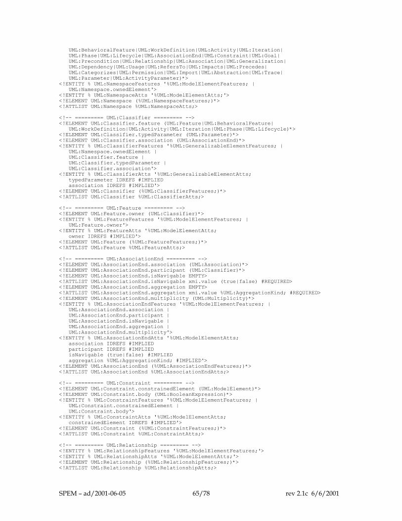
UML:BehavioralFeature|UML:WorkDefinition|UML:Activity|UML:Iteration| UML:Phase|UML:Lifecycle|UML:AssociationEnd|UML:Constraint|UML:Goal| UML:Precondition|UML:Relationship|UML:Association|UML:Generalization| UML:Dependency|UML:Usage|UML:RefersTo|UML:Impacts|UML:Precedes| UML:Categorizes|UML:Permission|UML:Import|UML:Abstraction|UML:Trace| UML:Parameter|UML:ActivityParameter)*> <!ENTITY % UML:NamespaceFeatures '%UML:ModelElementFeatures; | UML:Namespace.ownedElement'> <!ENTITY % UML:NamespaceAtts '%UML:ModelElementAtts;'> <!ELEMENT UML:Namespace (%UML:NamespaceFeatures;)*> <!ATTLIST UML:Namespace %UML:NamespaceAtts;> <!-- ========= UML:Classifier ========= --> <!ELEMENT UML:Classifier.feature (UML:Feature|UML:BehavioralFeature| UML:WorkDefinition|UML:Activity|UML:Iteration|UML:Phase|UML:Lifecycle)*> <!ELEMENT UML:Classifier.typedParameter (UML:Parameter)*> <!ELEMENT UML:Classifier.association (UML:AssociationEnd)*> <!ENTITY % UML:ClassifierFeatures '%UML:GeneralizableElementFeatures; | UML:Namespace.ownedElement | UML:Classifier.feature | UML:Classifier.typedParameter | UML:Classifier.association'> <!ENTITY % UML:ClassifierAtts '%UML:GeneralizableElementAtts; typedParameter IDREFS #IMPLIED association IDREFS #IMPLIED'> <!ELEMENT UML:Classifier (%UML:ClassifierFeatures;)*> <!ATTLIST UML:Classifier %UML:ClassifierAtts;> <!-- ========= UML:Feature ========= --> <!ELEMENT UML:Feature.owner (UML:Classifier)*> <!ENTITY % UML:FeatureFeatures '%UML:ModelElementFeatures; | UML:Feature.owner'> <!ENTITY % UML:FeatureAtts '%UML:ModelElementAtts; owner IDREFS #IMPLIED'> <!ELEMENT UML:Feature (%UML:FeatureFeatures;)*> <!ATTLIST UML:Feature %UML:FeatureAtts;> <!-- ========= UML:AssociationEnd ========= --> <!ELEMENT UML:AssociationEnd.association (UML:Association)*> <!ELEMENT UML:AssociationEnd.participant (UML:Classifier)*> <!ELEMENT UML:AssociationEnd.isNavigable EMPTY> <!ATTLIST UML:AssociationEnd.isNavigable xmi.value (true|false) #REQUIRED> <!ELEMENT UML:AssociationEnd.aggregation EMPTY> <!ATTLIST UML:AssociationEnd.aggregation xmi.value %UML:AggregationKind; #REQUIRED> <!ELEMENT UML:AssociationEnd.multiplicity (UML:Multiplicity)*> <!ENTITY % UML:AssociationEndFeatures '%UML:ModelElementFeatures; | UML:AssociationEnd.association | UML:AssociationEnd.participant | UML:AssociationEnd.isNavigable | UML:AssociationEnd.aggregation | UML:AssociationEnd.multiplicity'> <!ENTITY % UML:AssociationEndAtts '%UML:ModelElementAtts; association IDREFS #IMPLIED participant IDREFS #IMPLIED isNavigable (true|false) #IMPLIED aggregation %UML:AggregationKind; #IMPLIED'> <!ELEMENT UML:AssociationEnd (%UML:AssociationEndFeatures;)*> <!ATTLIST UML:AssociationEnd %UML:AssociationEndAtts;> <!-- ========= UML:Constraint ========= --> <!ELEMENT UML:Constraint.constrainedElement (UML:ModelElement)*> <!ELEMENT UML:Constraint.body (UML:BooleanExpression)*> <!ENTITY % UML:ConstraintFeatures '%UML:ModelElementFeatures; | UML:Constraint.constrainedElement | UML:Constraint.body'> <!ENTITY % UML:ConstraintAtts '%UML:ModelElementAtts; constrainedElement IDREFS #IMPLIED'> <!ELEMENT UML:Constraint (%UML:ConstraintFeatures;)*> <!ATTLIST UML:Constraint %UML:ConstraintAtts;> <!-- ========= UML:Relationship ========= --> <!ENTITY % UML:RelationshipFeatures '%UML:ModelElementFeatures;'> <!ENTITY % UML:RelationshipAtts '%UML:ModelElementAtts;'> <!ELEMENT UML:Relationship (%UML:RelationshipFeatures;)*> <!ATTLIST UML:Relationship %UML:RelationshipAtts;>
SPEM – ad/2001-06-05 65/78 rev 2.1c 6/6/2001
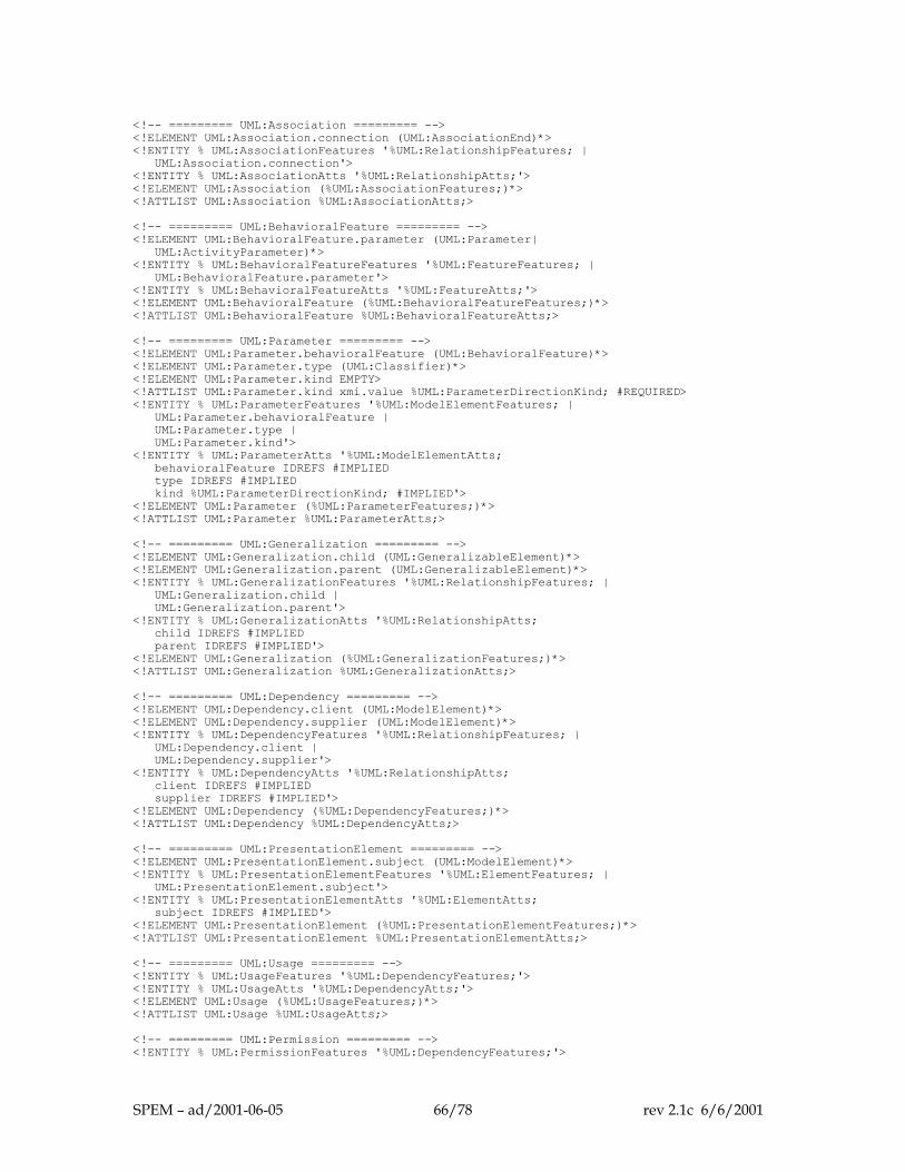
<!-- ========= UML:Association ========= --> <!ELEMENT UML:Association.connection (UML:AssociationEnd)*> <!ENTITY % UML:AssociationFeatures '%UML:RelationshipFeatures; | UML:Association.connection'> <!ENTITY % UML:AssociationAtts '%UML:RelationshipAtts;'> <!ELEMENT UML:Association (%UML:AssociationFeatures;)*> <!ATTLIST UML:Association %UML:AssociationAtts;> <!-- ========= UML:BehavioralFeature ========= --> <!ELEMENT UML:BehavioralFeature.parameter (UML:Parameter| UML:ActivityParameter)*> <!ENTITY % UML:BehavioralFeatureFeatures '%UML:FeatureFeatures; | UML:BehavioralFeature.parameter'> <!ENTITY % UML:BehavioralFeatureAtts '%UML:FeatureAtts;'> <!ELEMENT UML:BehavioralFeature (%UML:BehavioralFeatureFeatures;)*> <!ATTLIST UML:BehavioralFeature %UML:BehavioralFeatureAtts;> <!-- ========= UML:Parameter ========= --> <!ELEMENT UML:Parameter.behavioralFeature (UML:BehavioralFeature)*> <!ELEMENT UML:Parameter.type (UML:Classifier)*> <!ELEMENT UML:Parameter.kind EMPTY> <!ATTLIST UML:Parameter.kind xmi.value %UML:ParameterDirectionKind; #REQUIRED> <!ENTITY % UML:ParameterFeatures '%UML:ModelElementFeatures; | UML:Parameter.behavioralFeature | UML:Parameter.type | UML:Parameter.kind'> <!ENTITY % UML:ParameterAtts '%UML:ModelElementAtts; behavioralFeature IDREFS #IMPLIED type IDREFS #IMPLIED kind %UML:ParameterDirectionKind; #IMPLIED'> <!ELEMENT UML:Parameter (%UML:ParameterFeatures;)*> <!ATTLIST UML:Parameter %UML:ParameterAtts;> <!-- ========= UML:Generalization ========= --> <!ELEMENT UML:Generalization.child (UML:GeneralizableElement)*> <!ELEMENT UML:Generalization.parent (UML:GeneralizableElement)*> <!ENTITY % UML:GeneralizationFeatures '%UML:RelationshipFeatures; | UML:Generalization.child | UML:Generalization.parent'> <!ENTITY % UML:GeneralizationAtts '%UML:RelationshipAtts; child IDREFS #IMPLIED parent IDREFS #IMPLIED'> <!ELEMENT UML:Generalization (%UML:GeneralizationFeatures;)*> <!ATTLIST UML:Generalization %UML:GeneralizationAtts;> <!-- ========= UML:Dependency ========= --> <!ELEMENT UML:Dependency.client (UML:ModelElement)*> <!ELEMENT UML:Dependency.supplier (UML:ModelElement)*> <!ENTITY % UML:DependencyFeatures '%UML:RelationshipFeatures; | UML:Dependency.client | UML:Dependency.supplier'> <!ENTITY % UML:DependencyAtts '%UML:RelationshipAtts; client IDREFS #IMPLIED supplier IDREFS #IMPLIED'> <!ELEMENT UML:Dependency (%UML:DependencyFeatures;)*> <!ATTLIST UML:Dependency %UML:DependencyAtts;> <!-- ========= UML:PresentationElement ========= --> <!ELEMENT UML:PresentationElement.subject (UML:ModelElement)*> <!ENTITY % UML:PresentationElementFeatures '%UML:ElementFeatures; | UML:PresentationElement.subject'> <!ENTITY % UML:PresentationElementAtts '%UML:ElementAtts; subject IDREFS #IMPLIED'> <!ELEMENT UML:PresentationElement (%UML:PresentationElementFeatures;)*> <!ATTLIST UML:PresentationElement %UML:PresentationElementAtts;> <!-- ========= UML:Usage ========= --> <!ENTITY % UML:UsageFeatures '%UML:DependencyFeatures;'> <!ENTITY % UML:UsageAtts '%UML:DependencyAtts;'> <!ELEMENT UML:Usage (%UML:UsageFeatures;)*> <!ATTLIST UML:Usage %UML:UsageAtts;> <!-- ========= UML:Permission ========= --> <!ENTITY % UML:PermissionFeatures '%UML:DependencyFeatures;'>
SPEM – ad/2001-06-05 66/78 rev 2.1c 6/6/2001
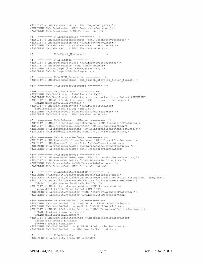
<!ENTITY % UML:PermissionAtts '%UML:DependencyAtts;'> <!ELEMENT UML:Permission (%UML:PermissionFeatures;)*> <!ATTLIST UML:Permission %UML:PermissionAtts;> <!-- ========= UML:Abstraction ========= --> <!ENTITY % UML:AbstractionFeatures '%UML:DependencyFeatures;'> <!ENTITY % UML:AbstractionAtts '%UML:DependencyAtts;'> <!ELEMENT UML:Abstraction (%UML:AbstractionFeatures;)*> <!ATTLIST UML:Abstraction %UML:AbstractionAtts;> <!-- ========= UML:Model_Management ========= --> <!-- ========= UML:Package ========= --> <!ENTITY % UML:PackageFeatures '%UML:NamespaceFeatures;'> <!ENTITY % UML:PackageAtts '%UML:NamespaceAtts;'> <!ELEMENT UML:Package (%UML:PackageFeatures;)*> <!ATTLIST UML:Package %UML:PackageAtts;> <!-- ========= UML:SPEM_Extensions ========= --> <!ENTITY % UML:PrecedenceKind '(pk_finish_start|pk_finish_finish)'> <!-- ========= UML:ProcessStructure ========= --> <!-- ========= UML:WorkProduct ========= --> <!ELEMENT UML:WorkProduct.isDeliverable EMPTY> <!ATTLIST UML:WorkProduct.isDeliverable xmi.value (true|false) #REQUIRED> <!ENTITY % UML:WorkProductFeatures '%UML:ClassifierFeatures; | UML:WorkProduct.isDeliverable'> <!ENTITY % UML:WorkProductAtts '%UML:ClassifierAtts; isDeliverable (true|false) #IMPLIED'> <!ELEMENT UML:WorkProduct (%UML:WorkProductFeatures;)*> <!ATTLIST UML:WorkProduct %UML:WorkProductAtts;> <!-- ========= UML:InformationElement ========= --> <!ENTITY % UML:InformationElementFeatures '%UML:ClassifierFeatures;'> <!ENTITY % UML:InformationElementAtts '%UML:ClassifierAtts;'> <!ELEMENT UML:InformationElement (%UML:InformationElementFeatures;)*> <!ATTLIST UML:InformationElement %UML:InformationElementAtts;> <!-- ========= UML:ProcessPerformer ========= --> <!ENTITY % UML:ProcessPerformerFeatures '%UML:ClassifierFeatures;'> <!ENTITY % UML:ProcessPerformerAtts '%UML:ClassifierAtts;'> <!ELEMENT UML:ProcessPerformer (%UML:ProcessPerformerFeatures;)*> <!ATTLIST UML:ProcessPerformer %UML:ProcessPerformerAtts;> <!-- ========= UML:ProcessRole ========= --> <!ENTITY % UML:ProcessRoleFeatures '%UML:ProcessPerformerFeatures;'> <!ENTITY % UML:ProcessRoleAtts '%UML:ProcessPerformerAtts;'> <!ELEMENT UML:ProcessRole (%UML:ProcessRoleFeatures;)*> <!ATTLIST UML:ProcessRole %UML:ProcessRoleAtts;> <!-- ========= UML:ActivityParameter ========= --> <!ELEMENT UML:ActivityParameter.hasWorkPerArtifact EMPTY> <!ATTLIST UML:ActivityParameter.hasWorkPerArtifact xmi.value (true|false) #REQUIRED> <!ENTITY % UML:ActivityParameterFeatures '%UML:ParameterFeatures; | UML:ActivityParameter.hasWorkPerArtifact'> <!ENTITY % UML:ActivityParameterAtts '%UML:ParameterAtts; hasWorkPerArtifact (true|false) #IMPLIED'> <!ELEMENT UML:ActivityParameter (%UML:ActivityParameterFeatures;)*> <!ATTLIST UML:ActivityParameter %UML:ActivityParameterAtts;> <!-- ========= UML:WorkDefinition ========= --> <!ELEMENT UML:WorkDefinition.parentWork (UML:WorkDefinition)*> <!ELEMENT UML:WorkDefinition.subWork (UML:WorkDefinition)*> <!ENTITY % UML:WorkDefinitionFeatures '%UML:BehavioralFeatureFeatures; | UML:WorkDefinition.parentWork | UML:WorkDefinition.subWork'> <!ENTITY % UML:WorkDefinitionAtts '%UML:BehavioralFeatureAtts; parentWork IDREFS #IMPLIED subWork IDREFS #IMPLIED'> <!ELEMENT UML:WorkDefinition (%UML:WorkDefinitionFeatures;)*> <!ATTLIST UML:WorkDefinition %UML:WorkDefinitionAtts;> <!-- ========= UML:Activity ========= --> <!ELEMENT UML:Activity.steps (UML:Step)*>
SPEM – ad/2001-06-05 67/78 rev 2.1c 6/6/2001
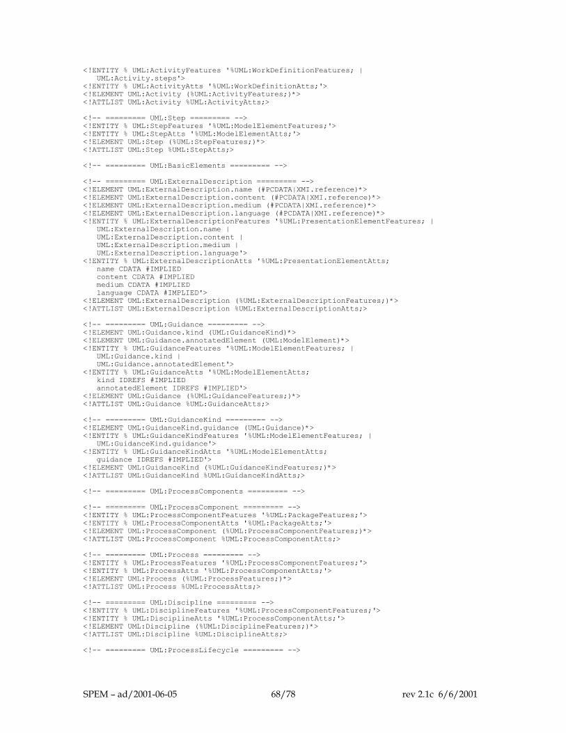
<!ENTITY % UML:ActivityFeatures '%UML:WorkDefinitionFeatures; | UML:Activity.steps'> <!ENTITY % UML:ActivityAtts '%UML:WorkDefinitionAtts;'> <!ELEMENT UML:Activity (%UML:ActivityFeatures;)*> <!ATTLIST UML:Activity %UML:ActivityAtts;> <!-- ========= UML:Step ========= --> <!ENTITY % UML:StepFeatures '%UML:ModelElementFeatures;'> <!ENTITY % UML:StepAtts '%UML:ModelElementAtts;'> <!ELEMENT UML:Step (%UML:StepFeatures;)*> <!ATTLIST UML:Step %UML:StepAtts;> <!-- ========= UML:BasicElements ========= --> <!-- ========= UML:ExternalDescription ========= --> <!ELEMENT UML:ExternalDescription.name (#PCDATA|XMI.reference)*> <!ELEMENT UML:ExternalDescription.content (#PCDATA|XMI.reference)*> <!ELEMENT UML:ExternalDescription.medium (#PCDATA|XMI.reference)*> <!ELEMENT UML:ExternalDescription.language (#PCDATA|XMI.reference)*> <!ENTITY % UML:ExternalDescriptionFeatures '%UML:PresentationElementFeatures; | UML:ExternalDescription.name | UML:ExternalDescription.content | UML:ExternalDescription.medium | UML:ExternalDescription.language'> <!ENTITY % UML:ExternalDescriptionAtts '%UML:PresentationElementAtts; name CDATA #IMPLIED content CDATA #IMPLIED medium CDATA #IMPLIED language CDATA #IMPLIED'> <!ELEMENT UML:ExternalDescription (%UML:ExternalDescriptionFeatures;)*> <!ATTLIST UML:ExternalDescription %UML:ExternalDescriptionAtts;> <!-- ========= UML:Guidance ========= --> <!ELEMENT UML:Guidance.kind (UML:GuidanceKind)*> <!ELEMENT UML:Guidance.annotatedElement (UML:ModelElement)*> <!ENTITY % UML:GuidanceFeatures '%UML:ModelElementFeatures; | UML:Guidance.kind | UML:Guidance.annotatedElement'> <!ENTITY % UML:GuidanceAtts '%UML:ModelElementAtts; kind IDREFS #IMPLIED annotatedElement IDREFS #IMPLIED'> <!ELEMENT UML:Guidance (%UML:GuidanceFeatures;)*> <!ATTLIST UML:Guidance %UML:GuidanceAtts;> <!-- ========= UML:GuidanceKind ========= --> <!ELEMENT UML:GuidanceKind.guidance (UML:Guidance)*> <!ENTITY % UML:GuidanceKindFeatures '%UML:ModelElementFeatures; | UML:GuidanceKind.guidance'> <!ENTITY % UML:GuidanceKindAtts '%UML:ModelElementAtts; guidance IDREFS #IMPLIED'> <!ELEMENT UML:GuidanceKind (%UML:GuidanceKindFeatures;)*> <!ATTLIST UML:GuidanceKind %UML:GuidanceKindAtts;> <!-- ========= UML:ProcessComponents ========= --> <!-- ========= UML:ProcessComponent ========= --> <!ENTITY % UML:ProcessComponentFeatures '%UML:PackageFeatures;'> <!ENTITY % UML:ProcessComponentAtts '%UML:PackageAtts;'> <!ELEMENT UML:ProcessComponent (%UML:ProcessComponentFeatures;)*> <!ATTLIST UML:ProcessComponent %UML:ProcessComponentAtts;> <!-- ========= UML:Process ========= --> <!ENTITY % UML:ProcessFeatures '%UML:ProcessComponentFeatures;'> <!ENTITY % UML:ProcessAtts '%UML:ProcessComponentAtts;'> <!ELEMENT UML:Process (%UML:ProcessFeatures;)*> <!ATTLIST UML:Process %UML:ProcessAtts;> <!-- ========= UML:Discipline ========= --> <!ENTITY % UML:DisciplineFeatures '%UML:ProcessComponentFeatures;'> <!ENTITY % UML:DisciplineAtts '%UML:ProcessComponentAtts;'> <!ELEMENT UML:Discipline (%UML:DisciplineFeatures;)*> <!ATTLIST UML:Discipline %UML:DisciplineAtts;> <!-- ========= UML:ProcessLifecycle ========= -->
SPEM – ad/2001-06-05 68/78 rev 2.1c 6/6/2001
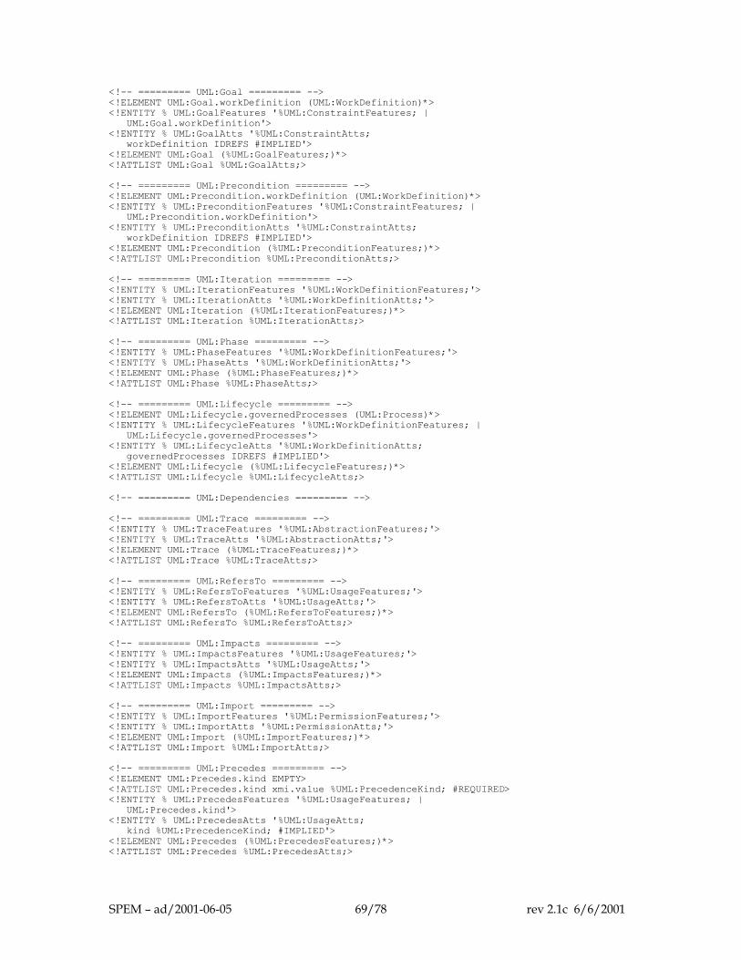
<!-- ========= UML:Goal ========= --> <!ELEMENT UML:Goal.workDefinition (UML:WorkDefinition)*> <!ENTITY % UML:GoalFeatures '%UML:ConstraintFeatures; | UML:Goal.workDefinition'> <!ENTITY % UML:GoalAtts '%UML:ConstraintAtts; workDefinition IDREFS #IMPLIED'> <!ELEMENT UML:Goal (%UML:GoalFeatures;)*> <!ATTLIST UML:Goal %UML:GoalAtts;> <!-- ========= UML:Precondition ========= --> <!ELEMENT UML:Precondition.workDefinition (UML:WorkDefinition)*> <!ENTITY % UML:PreconditionFeatures '%UML:ConstraintFeatures; | UML:Precondition.workDefinition'> <!ENTITY % UML:PreconditionAtts '%UML:ConstraintAtts; workDefinition IDREFS #IMPLIED'> <!ELEMENT UML:Precondition (%UML:PreconditionFeatures;)*> <!ATTLIST UML:Precondition %UML:PreconditionAtts;> <!-- ========= UML:Iteration ========= --> <!ENTITY % UML:IterationFeatures '%UML:WorkDefinitionFeatures;'> <!ENTITY % UML:IterationAtts '%UML:WorkDefinitionAtts;'> <!ELEMENT UML:Iteration (%UML:IterationFeatures;)*> <!ATTLIST UML:Iteration %UML:IterationAtts;> <!-- ========= UML:Phase ========= --> <!ENTITY % UML:PhaseFeatures '%UML:WorkDefinitionFeatures;'> <!ENTITY % UML:PhaseAtts '%UML:WorkDefinitionAtts;'> <!ELEMENT UML:Phase (%UML:PhaseFeatures;)*> <!ATTLIST UML:Phase %UML:PhaseAtts;> <!-- ========= UML:Lifecycle ========= --> <!ELEMENT UML:Lifecycle.governedProcesses (UML:Process)*> <!ENTITY % UML:LifecycleFeatures '%UML:WorkDefinitionFeatures; | UML:Lifecycle.governedProcesses'> <!ENTITY % UML:LifecycleAtts '%UML:WorkDefinitionAtts; governedProcesses IDREFS #IMPLIED'> <!ELEMENT UML:Lifecycle (%UML:LifecycleFeatures;)*> <!ATTLIST UML:Lifecycle %UML:LifecycleAtts;> <!-- ========= UML:Dependencies ========= --> <!-- ========= UML:Trace ========= --> <!ENTITY % UML:TraceFeatures '%UML:AbstractionFeatures;'> <!ENTITY % UML:TraceAtts '%UML:AbstractionAtts;'> <!ELEMENT UML:Trace (%UML:TraceFeatures;)*> <!ATTLIST UML:Trace %UML:TraceAtts;> <!-- ========= UML:RefersTo ========= --> <!ENTITY % UML:RefersToFeatures '%UML:UsageFeatures;'> <!ENTITY % UML:RefersToAtts '%UML:UsageAtts;'> <!ELEMENT UML:RefersTo (%UML:RefersToFeatures;)*> <!ATTLIST UML:RefersTo %UML:RefersToAtts;> <!-- ========= UML:Impacts ========= --> <!ENTITY % UML:ImpactsFeatures '%UML:UsageFeatures;'> <!ENTITY % UML:ImpactsAtts '%UML:UsageAtts;'> <!ELEMENT UML:Impacts (%UML:ImpactsFeatures;)*> <!ATTLIST UML:Impacts %UML:ImpactsAtts;> <!-- ========= UML:Import ========= --> <!ENTITY % UML:ImportFeatures '%UML:PermissionFeatures;'> <!ENTITY % UML:ImportAtts '%UML:PermissionAtts;'> <!ELEMENT UML:Import (%UML:ImportFeatures;)*> <!ATTLIST UML:Import %UML:ImportAtts;> <!-- ========= UML:Precedes ========= --> <!ELEMENT UML:Precedes.kind EMPTY> <!ATTLIST UML:Precedes.kind xmi.value %UML:PrecedenceKind; #REQUIRED> <!ENTITY % UML:PrecedesFeatures '%UML:UsageFeatures; | UML:Precedes.kind'> <!ENTITY % UML:PrecedesAtts '%UML:UsageAtts; kind %UML:PrecedenceKind; #IMPLIED'> <!ELEMENT UML:Precedes (%UML:PrecedesFeatures;)*> <!ATTLIST UML:Precedes %UML:PrecedesAtts;>
SPEM – ad/2001-06-05 69/78 rev 2.1c 6/6/2001

<!-- ========= UML:Categorizes ========= --> <!ENTITY % UML:CategorizesFeatures '%UML:UsageFeatures;'> <!ENTITY % UML:CategorizesAtts '%UML:UsageAtts;'> <!ELEMENT UML:Categorizes (%UML:CategorizesFeatures;)*> <!ATTLIST UML:Categorizes %UML:CategorizesAtts;>
SPEM – ad/2001-06-05 70/78 rev 2.1c 6/6/2001
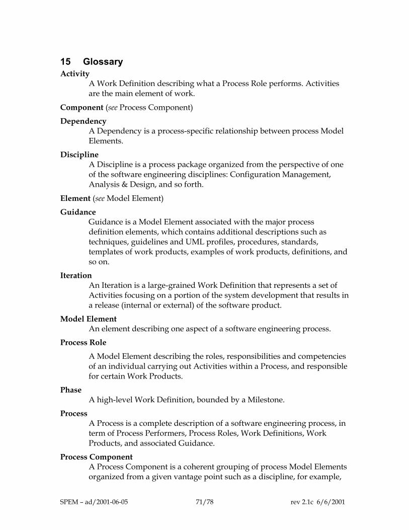
15 Glossary Activity
A Work Definition describing what a Process Role performs. Activities are the main element of work.
Component (see Process Component)
Dependency A Dependency is a process-specific relationship between process Model Elements.
Discipline A Discipline is a process package organized from the perspective of one of the software engineering disciplines: Configuration Management, Analysis & Design, and so forth.
Element (see Model Element)
Guidance Guidance is a Model Element associated with the major process definition elements, which contains additional descriptions such as techniques, guidelines and UML profiles, procedures, standards, templates of work products, examples of work products, definitions, and so on.
Iteration An Iteration is a large-grained Work Definition that represents a set of Activities focusing on a portion of the system development that results in a release (internal or external) of the software product.
Model Element An element describing one aspect of a software engineering process.
Process Role
A Model Element describing the roles, responsibilities and competencies of an individual carrying out Activities within a Process, and responsible for certain Work Products.
Phase A high-level Work Definition, bounded by a Milestone.
Process A Process is a complete description of a software engineering process, in term of Process Performers, Process Roles, Work Definitions, Work Products, and associated Guidance.
Process Component A Process Component is a coherent grouping of process Model Elements organized from a given vantage point such as a discipline, for example,
SPEM – ad/2001-06-05 71/78 rev 2.1c 6/6/2001
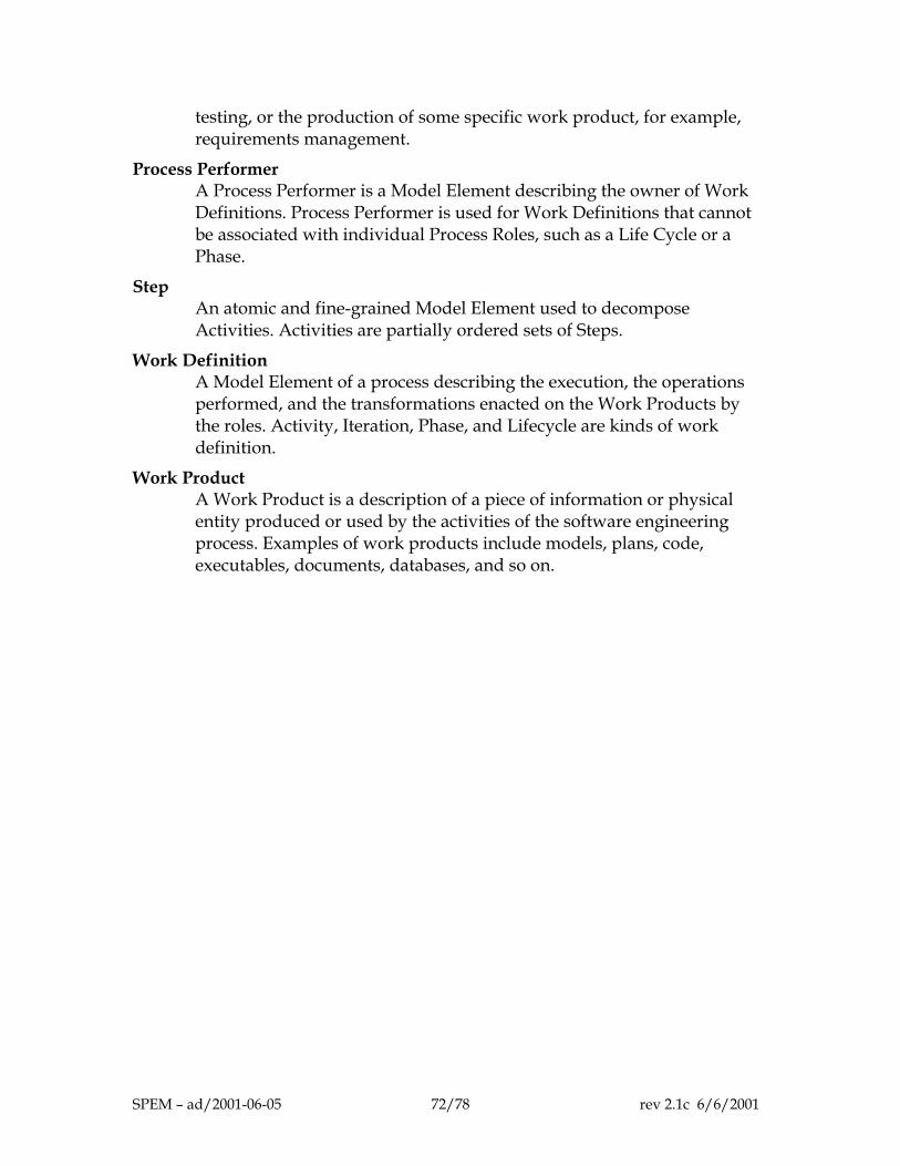
testing, or the production of some specific work product, for example, requirements management.
Process Performer A Process Performer is a Model Element describing the owner of Work Definitions. Process Performer is used for Work Definitions that cannot be associated with individual Process Roles, such as a Life Cycle or a Phase.
Step An atomic and fine-grained Model Element used to decompose Activities. Activities are partially ordered sets of Steps.
Work Definition A Model Element of a process describing the execution, the operations performed, and the transformations enacted on the Work Products by the roles. Activity, Iteration, Phase, and Lifecycle are kinds of work definition.
Work Product A Work Product is a description of a piece of information or physical entity produced or used by the activities of the software engineering process. Examples of work products include models, plans, code, executables, documents, databases, and so on.
SPEM – ad/2001-06-05 72/78 rev 2.1c 6/6/2001
16 References This chapter is not by any means intended to cover the whole literature on process and process modeling (see the extensive bibliography given in [6]), but to give the principal sources we have used in elaborating this specification. 1. Rational Unified Process (RUP) 2000, Rational Software Corporation, Cupertino, CA (2000) 2. Ivar Jacobson, et al., Object-oriented Software Engineering—A Use Case Driven Approach,
Addison-Wesley (1992). 3. Philippe Kruchten, The Rational Unified Process—An Introduction, 2nd ed, Addison-Wesley-
Longman, Reading, MA (2000) 4. Ian Graham, Brian Henderson-Sellers, and HoumanYounessi, The OPEN Process Specification,
Addison-Wesley, London, UK, 1997, 314pp 5. B. Henderson-Sellers, S. Mellor, “Tailoring process methodologies,” ROAD/JOOP, Volume 12
no 4, July/Aug 1999 6. Jean-Claude Derniame, et al., Software Process: Principles, Methodology, and Technology, LNCS
#1500, Springer-Verlag, 1999. 7. Ivar Jacobson, Grady Booch, Jim Rumbaugh, The Unified Software Development Process,
Addison-Wesley-Longman (1999) 8. Grady Booch, et al., UML User’s Guide, Addison-Wesley-Longman, Reading, MA (1999) 9. Desmond D’Souza & Alan Wills, Objects, Components and Framework with UML—The Catalysis
Approach, Addison-Wesley–Longman (1998) 10. Jennifer Stapleton, DSDM—Dynamic Systems Development Method, Addison-Wesley (1998) 11. Walker Royce, Software Project Management—A Unified Framework, Addison-Wesley-Longman
(1998) 12. IBM, Developing Object-Oriented Software—An Experience-Based Approach, Prentice-Hall (1997) 13. Derek Coleman et al., OOD—The Fusion Method, Prentice-Hall (1994) 14. Alfonso Fuggetta & Alexander Wolf (eds.), Software Process, J. Wiley & Sons (1996) 15. Scott Ambler, Process Patterns—Building Large-Scale Systems using Object technology, SIGS
Books Cambridge University Press (1998) 16. Barry Boehm, “Anchoring the Software Process,” IEEE Software, July 1996, 73-82. 17. OMG, RFP for Software Process Engineering, 1.0, November 1999 18. ISO/IEC 12207 Information technology–Software life-cycle processes, ISO, Geneva, 1995 19. IEEE 1074-1997, Standard for developing software life cycle processes, NY, NY 1997 20. I. Jacobson and S. Jacobson, “ Reengineering your software engineering process,” Object
Magazine, March 1995. 21. C. Larman, Applying UML and Patterns—An Introduction to Object-Oriented Analysis and
Design, Prentice-Hall (1997) 22. S. Cook and J. Daniels, Designing Object Systems: object-oriented modelling with Syntropy,
Prentice-Hall (1994) 23. DMR Consulting, DMR Macroscope, Version 3.1, April 2000 24. M. J. Presso, G. Raymond, M. Belaunde, “PILOTE: A Tool Suite to Support UML-based
Engineering Processes,” Proc. of 4th International EDOC Conference, Makuhari, Japan,, IEEE Computer Society, Sept. 2000
25. Jun Ginbayashi, Rieko Yamamoto, Keiji Hashimoto, "Business Component Framework and Modeling Method for Component-based Application Architecture," Proc. of 4th International EDOC Conference, Makuhari, Japan, IEEE Computer Society, Sept.2000, pp184-193.
26. Itakura, M., “SDEM90: A framework for system development activities and responsibilities,” Proc. of the 2nd International Conf. on System Integration, Morristown, N.J., 1992, pp. 359-363
SPEM – ad/2001-06-05 73/78 rev 2.1c 6/6/2001

27. Unisys QuadCycle : A full life cycle component based development and deployment methodology based on Rational Unified Process and Unisys TeamMethod http://www.unisys.com/news/releases/1999/oct/10276812.html
SPEM – ad/2001-06-05 74/78 rev 2.1c 6/6/2001
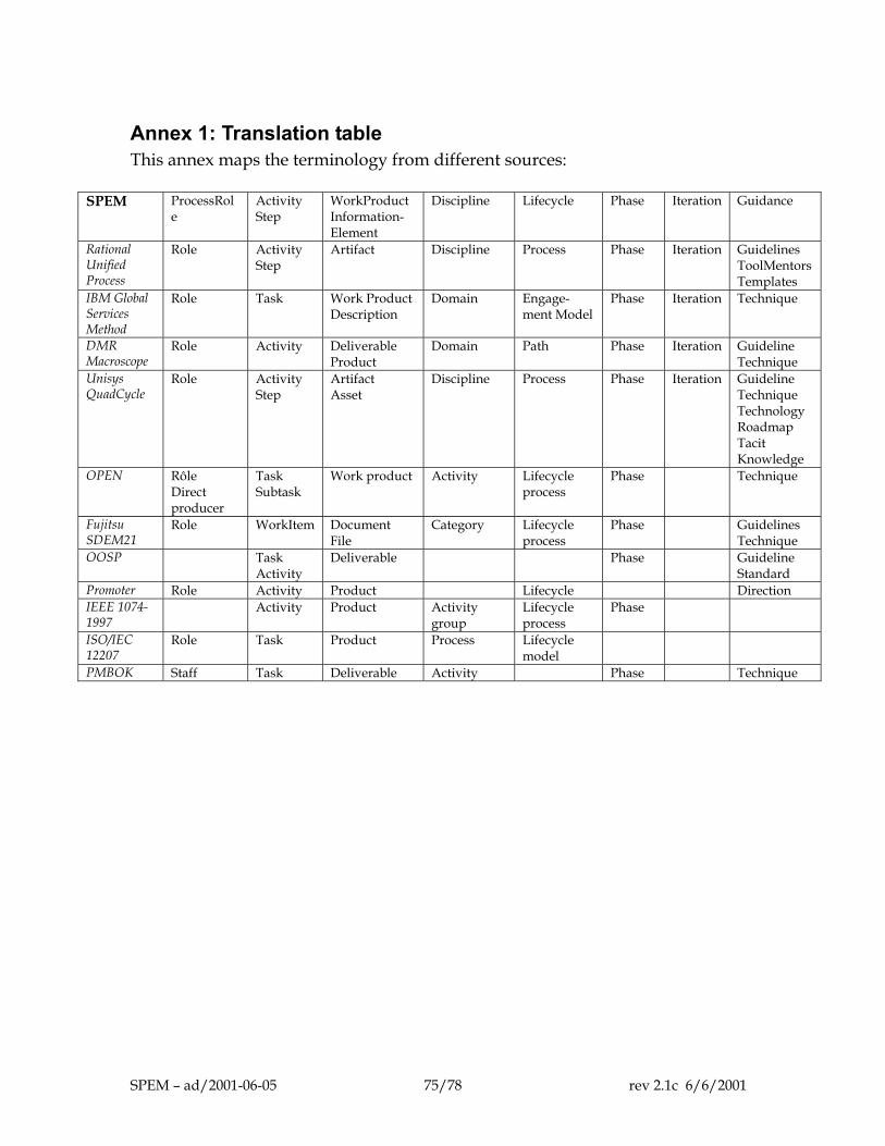
Annex 1: Translation table This annex maps the terminology from different sources:
SPEM ProcessRol
e Activity Step
WorkProduct Information- Element
Discipline Lifecycle Phase Iteration Guidance
Rational Unified Process
Role Activity Step
Artifact Discipline Process Phase Iteration Guidelines ToolMentors Templates
IBM Global Services Method
Role Task Work Product Description
Domain Engage- ment Model
Phase Iteration Technique
DMR Macroscope
Role Activity Deliverable Product
Domain Path Phase Iteration Guideline Technique
Unisys QuadCycle
Role Activity Step
Artifact Asset
Discipline Process Phase Iteration Guideline Technique Technology Roadmap Tacit Knowledge
OPEN Rôle Direct producer
Task Subtask
Work product Activity Lifecycle process
Phase Technique
Fujitsu SDEM21
Role WorkItem Document File
Category Lifecycle process
Phase Guidelines Technique
OOSP Task Activity
Deliverable Phase Guideline Standard
Promoter Role Activity Product Lifecycle Direction IEEE 1074-1997
Activity Product Activity group
Lifecycle process
Phase
ISO/IEC 12207
Role Task Product Process
PMBOK Staff Task Deliverable Activity Phase Technique
Lifecycle model
SPEM – ad/2001-06-05 75/78 rev 2.1c 6/6/2001
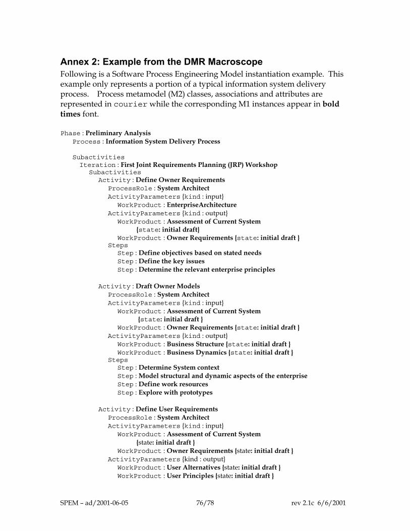
Annex 2: Example from the DMR Macroscope Following is a Software Process Engineering Model instantiation example. This example only represents a portion of a typical information system delivery process. Process metamodel (M2) classes, associations and attributes are represented in courier while the corresponding M1 instances appear in bold times font. Phase : Preliminary Analysis Process : Information System Delivery Process Subactivities Iteration : First Joint Requirements Planning (JRP) Workshop Subactivities Activity : Define Owner Requirements ProcessRole : System Architect ActivityParameters {kind : input} WorkProduct : EnterpriseArchitecture ActivityParameters {kind : output} WorkProduct : Assessment of Current System {state: initial draft} WorkProduct : Owner Requirements {state: initial draft } Steps Step : Define objectives based on stated needs Step : Define the key issues Step : Determine the relevant enterprise principles Activity : Draft Owner Models ProcessRole : System Architect ActivityParameters {kind : input} WorkProduct : Assessment of Current System {state: initial draft } WorkProduct : Owner Requirements {state: initial draft } ActivityParameters {kind : output} WorkProduct : Business Structure {state: initial draft } WorkProduct : Business Dynamics {state: initial draft } Steps Step : Determine System context Step : Model structural and dynamic aspects of the enterprise Step : Define work resources Step : Explore with prototypes Activity : Define User Requirements ProcessRole : System Architect ActivityParameters {kind : input} WorkProduct : Assessment of Current System {state: initial draft } WorkProduct : Owner Requirements {state: initial draft } ActivityParameters {kind : output} WorkProduct : User Alternatives {state: initial draft } WorkProduct : User Principles {state: initial draft }
SPEM – ad/2001-06-05 76/78 rev 2.1c 6/6/2001
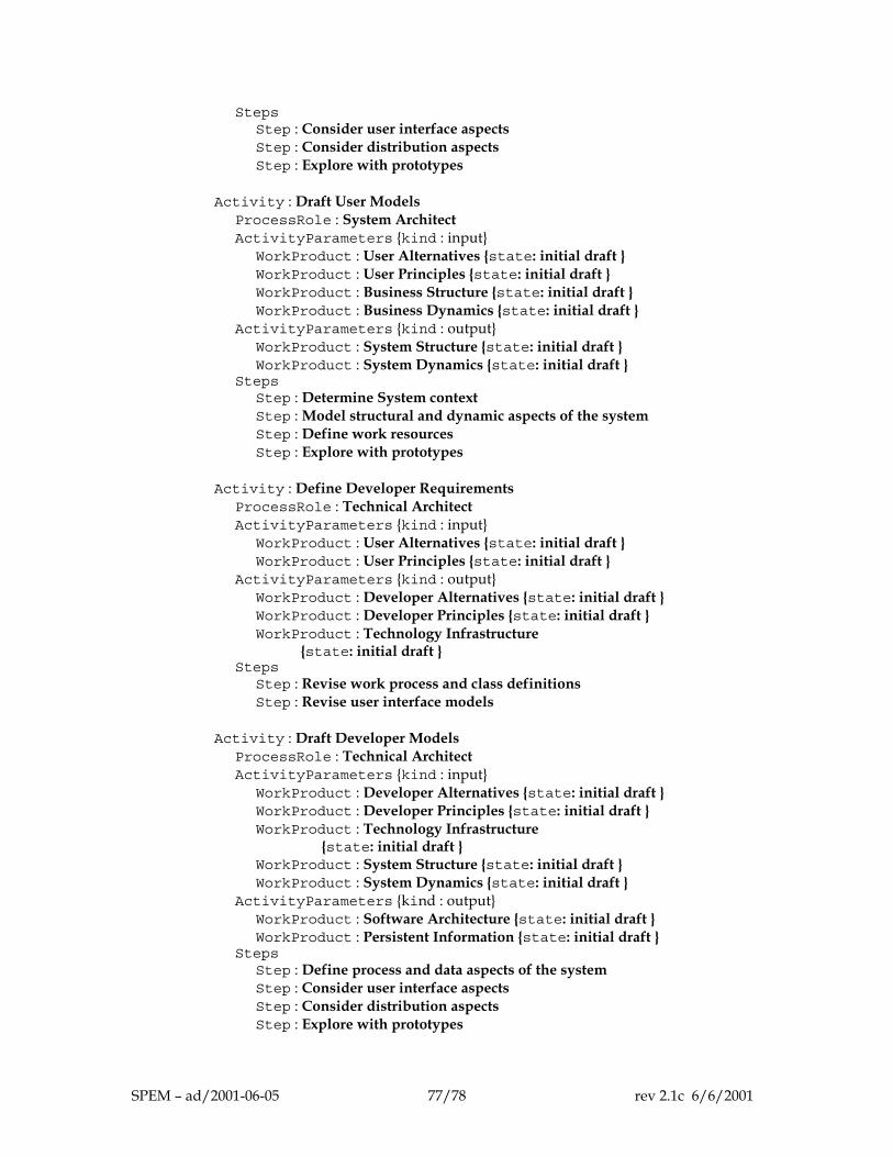
Steps Step : Consider user interface aspects Step : Consider distribution aspects Step : Explore with prototypes Activity : Draft User Models ProcessRole : System Architect ActivityParameters {kind : input} WorkProduct : User Alternatives {state: initial draft } WorkProduct : User Principles {state: initial draft } WorkProduct : Business Structure {state: initial draft } WorkProduct : Business Dynamics {state: initial draft } ActivityParameters {kind : output} WorkProduct : System Structure {state: initial draft } WorkProduct : System Dynamics {state: initial draft } Steps Step : Determine System context Step : Model structural and dynamic aspects of the system Step : Define work resources Step : Explore with prototypes Activity : Define Developer Requirements ProcessRole : Technical Architect ActivityParameters {kind : input} WorkProduct : User Alternatives {state: initial draft } WorkProduct : User Principles {state: initial draft } ActivityParameters {kind : output} WorkProduct : Developer Alternatives {state: initial draft } WorkProduct : Developer Principles {state: initial draft } WorkProduct : Technology Infrastructure {state: initial draft } Steps Step : Revise work process and class definitions Step : Revise user interface models Activity : Draft Developer Models ProcessRole : Technical Architect ActivityParameters {kind : input} WorkProduct : Developer Alternatives {state: initial draft } WorkProduct : Developer Principles {state: initial draft } WorkProduct : Technology Infrastructure {state: initial draft } WorkProduct : System Structure {state: initial draft } WorkProduct : System Dynamics {state: initial draft } ActivityParameters {kind : output} WorkProduct : Software Architecture {state: initial draft } WorkProduct : Persistent Information {state: initial draft } Steps Step : Define process and data aspects of the system Step : Consider user interface aspects Step : Consider distribution aspects Step : Explore with prototypes
SPEM – ad/2001-06-05 77/78 rev 2.1c 6/6/2001
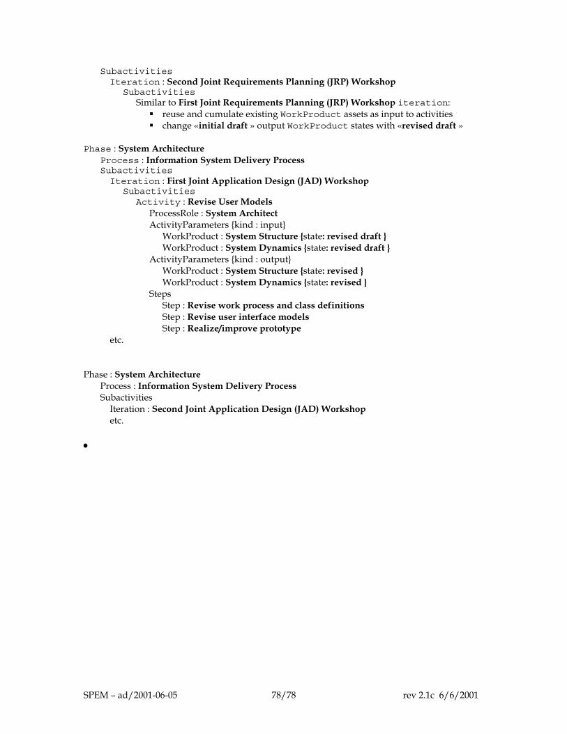
Subactivities Iteration : Second Joint Requirements Planning (JRP) Workshop Subactivities Similar to First Joint Requirements Planning (JRP) Workshop iteration:
reuse and cumulate existing WorkProduct assets as input to activities change «initial draft » output WorkProduct states with «revised draft »
Phase : System Architecture Process : Information System Delivery Process Subactivities Iteration : First Joint Application Design (JAD) Workshop Subactivities Activity : Revise User Models ProcessRole : System Architect ActivityParameters {kind : input} WorkProduct : System Structure {state: revised draft } WorkProduct : System Dynamics {state: revised draft } ActivityParameters {kind : output} WorkProduct : System Structure {state: revised } WorkProduct : System Dynamics {state: revised } Steps Step : Revise work process and class definitions Step : Revise user interface models Step : Realize/improve prototype etc. Phase : System Architecture Process : Information System Delivery Process Subactivities Iteration : Second Joint Application Design (JAD) Workshop etc. •
SPEM – ad/2001-06-05 78/78 rev 2.1c 6/6/2001


![Software Engineering: [Process]](https://img.dokumen.tips/doc/110x75/61570732a097e25c765049b2/software-engineering-process.jpg)