Embed Size (px)
Citation preview
�������������� ������������
Version 4.0 093-0905-000 Rev.A
Copyright Notice
Copyright © 2003 NetScreen Technologies, Inc. All rights reserved.
NetScreen, NetScreen Technologies, GigaScreen, and the NetScreen logo are registered trademarks of NetScreen Technologies, Inc. NetScreen-5XP, NetScreen-5XT, NetScreen-25, NetScreen-50, NetScreen-100, NetScreen-204, NetScreen-208, NetScreen-500, NetScreen-1000, NetScreen-5200, NetScreen-5400, NetScreen-Global PRO, NetScreen-Global PRO Express, NetScreen-Remote Security Client, NetScreen-Remote VPN Client, NetScreen-IDP 100, NetScreen-IDP 500, GigaScreen ASIC, GigaScreen-II ASIC, and NetScreen ScreenOS are trademarks of NetScreen Technologies, Inc. All other trademarks and registered trademarks are the property of their respective companies.
Information in this document is subject to change without notice.
No part of this document may be reproduced or transmitted in any form or by any means, electronic or mechanical, for any purpose, without receiving written permission from:
NetScreen Technologies, Inc.Building #3805 11th AvenueSunnyvale, CA 94089www.netscreen.com
FCC Statement
The following information is for FCC compliance of Class A devices: This equipment has been tested and found to comply with the limits for a Class A digital device, pursuant to part 15 of the FCC rules. These limits are designed to provide reasonable protection against harmful interference when the equipment is operated in a commercial environment. The equipment generates, uses, and can radiate radio-frequency energy and, if not installed and used in accordance with the instruction manual, may cause harmful interference to radio communications. Operation of this equipment in a residential area is likely to cause harmful interference, in which case users will be required to correct the interference at their own expense.
The following information is for FCC compliance of Class B devices: The equipment described in this manual generates and may radiate radio-frequency energy. If it is not installed in accordance with NetScreen’s installation instructions, it may cause interference with Radio and television reception. This equipment has been tested and found to comply with the limits for a Class B digital devices in accordance with the specifications in part 15 of the FCC rules. These specifications are designed to provide reasonable protection against such interference in a residential installation. However, there is no guarantee that interference will not occur in a particular installation.
If this equipment does cause harmful interference to radio or television reception, which can be determined by turning the equipment off and on, the user is encouraged to try to correct the interference by one or more of the following measures:
• Reorient or relocate the receiving antenna.
• Increase the separation between the equipment and receiver.
• Consult the dealer or an experienced radio/TV technician for help.
• Connect the equipment to an outlet on a circuit different from that to which the receiver is connected.
Caution: Changes or modifications to this product could void the user's warranty and authority to operate this device.
Disclaimer
THE SOFTWARE LICENSE AND LIMITED WARRANTY FOR THE ACCOMPANYING PRODUCT ARE SET FORTH IN THE INFORMATION PACKET THAT SHIPPED WITH THE PRODUCT AND ARE INCORPORATED HEREIN BY THIS REFERENCE. IF YOU ARE UNABLE TO LOCATE THE SOFTWARE LICENSE OR LIMITED WARRANTY, CONTACT YOUR NETSCREEN REPRESENTATIVE FOR A COPY.
� ������������������� ���������������������������������������������������������������������������������������������������������������������� �
�������� ��� ����� ��������������������������������������������������������������������������������������
���� �������������� ��� ���!���������������������������������������������������������������������� ���" �� ���� ��������������������������������������������������������������������������������� ��
" �� ������� �������������������������������������������������������������������������������������������� �������������" �� ����� ���� ������������������������������������������������������������������� ��
�������� ����#�� $������������������������������������������������������������������������������������ ����%�&������#�%���������� ���������������������������������������������������������������������������� ����������%�&��������������������������������������������������������������������������������������������'� �� �����#������������ ���� ���(� �������������������������������������������������������
���������������� ������������������������������������������������������������������������������������� �$
)�*�������+���������� ����� ��������������������������������������������������������������������� �$
�, &����-���������* �����������������������������������������������������������������������������������������������-
����� �����*�������������� ������������������������������������������������������������������������ .
�� �����/%�� �������������������������������������������������������������������������������������������������� 0�����&��������� �����/%�������,��%����� �������������������������������������������������������������1�����&�������������� �����/%� ������������������������������������������������������������������������������1
�, &����.������ �������,��%����� ������������������������������������������������������������������������������
%��2��&����� �� ���������������������������������������������������������������������������������� 3
������������,����*����������������������������������������������������������������������������������� 3
������������,��������������%���������4�������*��2����������������������������� 5������������,��%��������� ��/$���� ��6����� ��������������������������������������������������5������������,��%���������4���������� �����*��2����7��2�� ��������������������������5
�, &����0���������������,��%����� �������������������������������������������������������������������������8
�&�� ���� ��+����� ���������������������������������������������������������������������������������� -9�� ��& �����+��� ������������������������������������������������������������������������������������������-96�����+�������������������������������������������������������������������������������������������������������-9
�,�������������������� ���� ������������������������������������������������������������������ --
/�� ����,���� ����������������� ����������������������������������������������������������������� -.
�, ������4����������� ��� ���� ��*�������������������������������������������������� -.
�����+����������������������������������������������������������������������������������������������������� -0
�������� �����'�����������+ � ������,��%������ ��������������������������������������� -
'����������,���#�����:������,��7��:������������������������������������������������������� -
���������,�������+��������,�������������� ������������������������������������������� -5/$ �&��;���������)����7��2������+��� ��������������������������������������������������������-5
:������,��7��:��7�� ������������������,��%������������������������������������������ -<
����������� ���

�� ���������������
6����������,��%���������( ����#�%�� ������������� �������������������������������������� -8:������������� �������6������,��%����� �����������������������������������������������������-8:������,��'�����6������#����,�������6������,��%����� �����������������������������������.9
'&&����$�'���&������ ����� ������������������������������������������������������������������������������������'��
������������'���������� ������������������������������������������������������������������������� '���
/������� ���&������ ��������������������������������������������������������������������������������� '���
/���������� �� ������������������������������������������������������������������������������������������ '���
� ���#��������� ������ ��������������������������������������������������������������������������������� '���
/+���������� ������ ������������������������������������������������������������������������������������ '����
����������� ��������������������������������������������������������������������������������������������� '����
����$��������������������������������������������������������������������������������������������������������������������� �>��
�� ���� ����=������

�������The NetScreen-5GT device provides IPSec VPN and firewall services for a broadband telecommuter, a branch office, or a retail outlet. While at the entry level of the NetScreen appliance product line, the NetScreen-5GT device uses the same firewall, VPN, and traffic management technology as NetScreen’s high-end central site products.
NetScreen offers two versions of the NetScreen-5GT device:
• The 10-user version supports up to 10 users• The NS-5GT Plus version supports an unrestricted number of users, plus the
following additional features: OSPF (Open Shortest Path First), BGP (Border Gateway Protocol), Dial Backup, and Dual Untrust.
���� ������� �This manual has three chapters and one appendix.
Chapter 1, "Overview" provides an overview of the NetScreen-5GT device, ports, and power requirements.
Chapter 2, "Installing the Device" details how to install the NetScreen-5GT device on a desktop, connect the power, and connect the device to your network.
Chapter 3, "Configuring the Device" details how to establish a Console session, set an IP address for managing the NetScreen-5GT device, and access the device using the WebUI.
Appendix A, "Specifications" provides a list of physical specifications about the NetScreen-5GT device.
� ������������������������ ����� ��Some of the instructions and examples provided in this manual contain CLI commands, most of which perform initial configuration of the NetScreen-5GT device. The command examples use conventions for variables and syntax.
�������� ���" �� ����Most NetScreen CLI commands have changeable parameters that affect the outcome of command execution. NetScreen documention represents these parameters as variables. Such variables may include names, identification numbers, IP addresses, subnet masks, numbers, dates, and other values.
����������� �
����� ��
" �� ������� ����The variable notation used in this manual consists of italicized parameter identifiers. For example, the set arp command uses four identifiers, as shown here:
set arp{ip_addr mac_addr interfaceage number |always-on-dest |no-cache}
where
• ip_addr represents an IP address.• mac_addr represents a MAC address.• interface represents a physical or logical interface.• number represents a numerical value.
Thus, the command might take the following form:
ns-> set arp 172.16.10.11 00e02c000080 ethernet2
where 172.16.10.11 is an IP address, 00e02c000080 is a MAC address, and ethernet2 is a physical interface.
�����������" �� ����� ���The following list shows the CLI variable names used in NetScreen documents.
comm_name The community name of a host or other device.
date_str A date value.
dev_name A device name, as with flash card memory.
dom_name A domain name, such as “acme” in www.acme.com.
dst_addr A destination address, as with a policy definition that defines a source and destination IP address.
filename The name of a file.
grp_name The name of a group, such as an address group or service group.
interface A physical or logical interface.
id_num An identification number.
ip_addr An IP address.
key_str A key, such as a session key, a private key, or a public key.
key_hex A key expressed as a hexadecimal number.
loc_str A location of a file or other resource.
mac_addr A MAC address.
�� ���� ����=������

���� �������������� ��� ���!������������
Some commands contain multiple variables of the same type. The names of such variables may be numbered to identify each individually. For example, the set dip command contains two id_num variables, each numbered for easy identification:
set dip group id_num1 [ member id_num2 ]
�������� ����#�� $Each CLI command description in this manual reveals some aspect of command syntax. This syntax may include options, switches, parameters, and other features. To illustrate syntax rules, some command descriptions use dependency delimiters. Such delimiters indicate which command features are mandatory, and in which contexts.
%�&������#�%���������Each syntax description shows the dependencies between command features by using special characters.
mbr_name The name of a member in a group, such as an address group or a service group.
mask A subnet mask, such as 255.255.255.224 or /24.
name_str The name of an item, such as an address book entry.
number A numeric value, usually an integer, such as a threshold or a maximum.
pol_num A policy number.
port_num A number identifying a logical port.
pswd_str A password.
ptcl_num A number uniquely identifying a protocol, such as TCP, IP, or UDP.
serv_name The name of a server.
shar_secret A shared secret value.
spi_num A Security Parameters Index (SPI) number.
src_addr A source address, as with a policy definition that defines a source and destination IP address.
string A character string, such as a comment.
svc_name The name of a service, such at HTTP or MAIL.
time_str A time value.
tunn_str The name of a tunnel, such as an L2TP tunnel.
url_str A URL, such as www.acme.com.
usr_str A user, usually an External entity such as a dialup user.
vrouter A local virtual router, such as trust-vr or untrust-vr.
zone The name of a security zone.
����������� ���
����� ��
• The { and } symbols denote a mandatory feature. Features enclosed by these symbols are essential for execution of the command.
• The [ and ] symbols denote an optional feature. Features enclosed by these symbols are not essential for execution of the command, although omitting such features might adversely affect the outcome.
• The | symbol denotes an “or” relationship between two features. When this symbol appears between two features on the same line, you can use either feature (but not both). When this symbol appears at the end of a line, you can use the feature on that line, or the one below it.
�������%�&���������Many CLI commands have nested dependencies, which make features optional in some contexts, and mandatory in others. The three hypothetical features shown below demonstrate this principle.
[ feature_1 { feature_2 | feature_3 } ]
In this example, the delimiters [ and ] surround the entire clause. Consequently, you can omit feature_1, feature_2, and feature_3, and still execute the command successfully. However, because the { and } delimiters surround feature_2 and feature_3, you must include either feature_2 or feature_3 if you include feature_1. Otherwise, you cannot successfully execute the command.
The following example shows some of the set interface command’s feature dependencies.
set interface vlan1 broadcast { flood | arp [ trace-route ] }
The { and } brackets indicate that specifyng either flood or arp is mandatory. By contrast, the [ and ] brackets indicate that the arp option’s trace-route switch is not mandatory. Thus, the command might take any of the following forms:
ns-> set interface vlan1 broadcast floodns-> set interface vlan1 broadcast arpns-> set interface vlan1 broadcast arp trace-route
'� �� �����#������������ ���� ���(� �����As you execute CLI commands using the syntax descriptions in this manual, you may find that certain commands and command features are unavailable for your NetScreen device model.
Because NetScreen devices treat unavailable command features as improper syntax, attempting to use such a feature usually generates the unknown keyword error message. When this message appears, confirm the feature’s availability using the ? switch. For example, the following commands list available options for the set vpn command:
ns-> set vpn ?ns-> set vpn vpn_name ?ns-> set vpn gateway gate_name ?
���� ���� ����=������

���������������� �����
����������������� ��To obtain technical documentation for any NetScreen product, visit www.netscreen.com/support/manuals.html. To access the latest NetScreen documentation, see the Current Manuals section. To access archived documentation from previous releases, see the Archived Manuals section.
To obtain the latest technical information on a NetScreen product release, see the release notes document for that release. To obtain release notes, visit www.netscreen.com/support and select Software Download. Select the product and version, then click Go. (To perform this download, you must be a registered user.)
If you find any errors or omissions in the following content, please contact us at the e-mail address below:
� ��� ������ ����� ���� �To receive important news on product updates, please visit our Web site at www.netscreen.com.
����������� �$

����� ��
$ ���� ����=������
-���������
������ This chapter provides detailed descriptions of the NetScreen-5GT chassis.
Topics explained in this chapter include:
• “Port and Power Connectors” on page 2• “Status LEDs” on page 3
Note: For safety warnings and instructions, please refer to the NetScreen Safety Guide. The instructions in this guide warn you about situations that could cause bodily injury. Before working on any equipment, be aware of the hazards involved with electrical circuitry and be familiar with standard practices for preventing accidents.
NetScreen-5GT 1
Chapter 1 Overview
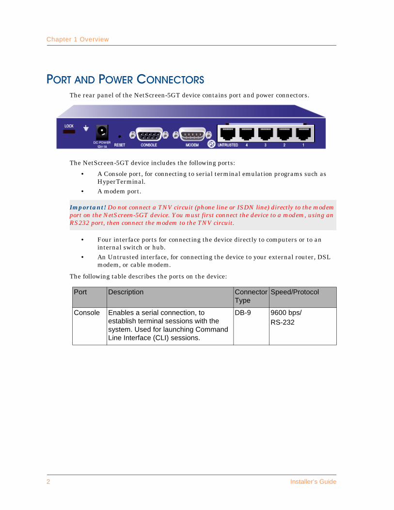
� ������� ����� ����� ��The rear panel of the NetScreen-5GT device contains port and power connectors.
The NetScreen-5GT device includes the following ports:
• A Console port, for connecting to serial terminal emulation programs such as HyperTerminal.
• A modem port.
• Four interface ports for connecting the device directly to computers or to an internal switch or hub.
• An Untrusted interface, for connecting the device to your external router, DSL modem, or cable modem.
The following table describes the ports on the device:
Important! Do not connect a TNV circuit (phone line or ISDN line) directly to the modem port on the NetScreen-5GT device. You must first connect the device to a modem, using an RS232 port, then connect the modem to the TNV circuit.
Port Description ConnectorType
Speed/Protocol
Console Enables a serial connection, to establish terminal sessions with the system. Used for launching Command Line Interface (CLI) sessions.
DB-9 9600 bps/RS-232
2 Installer’s Guide

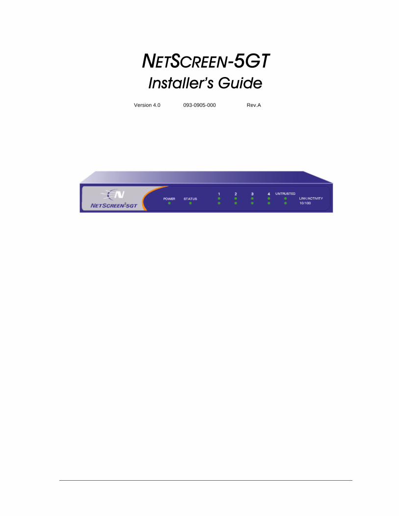
Status LEDs
The NetScreen-5GT device runs at 100-240 VAC +/- 10% (AC volts) and 12 watts. When properly connected to an AC power source, the power LED on the faceplate glows solid green. When power fails, the power LED turns off.
����������The front panel of the NetScreen-5GT device has power and status LEDs for the device, and port status LEDs for the interfaces.
Modem High-speed modem port. DB-9 9600 bps-115 Kbps/RS-232
Ports 1-4 Enables direct connections to workstations or a LAN connection through a switch or hub. This connection also allows you to manage the device through a Telnet session or the WebUI management application. You can also configure the ports to support different port modes, such as Home-Work mode.
RJ-45 10/100 Mbps/Ethernet
Untrusted Enables an Internet connection through an external router, DSL modem, or cable modem.
RJ-45 10/100 Mbps/Ethernet
Important! NetScreen recommends using a surge protector for the power connection.
Power LED Status LED Port Status LEDs
NetScreen-5GT 3
Chapter 1 Overview
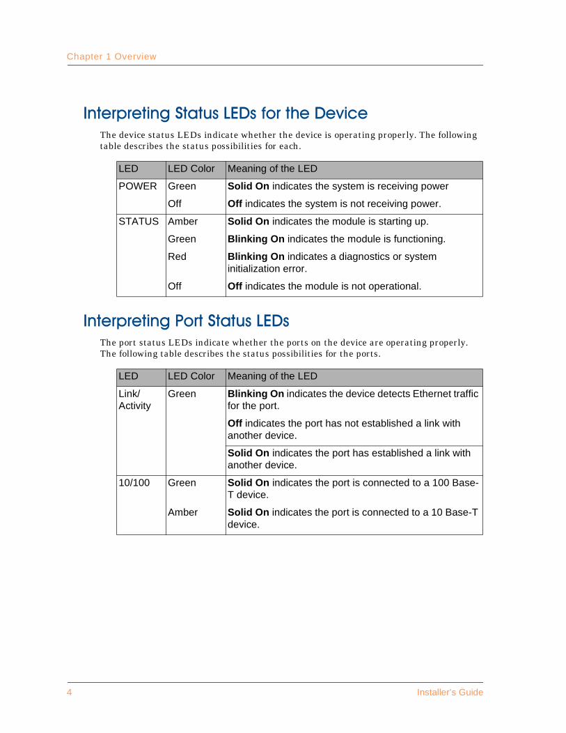
�����&��������� �����/%�������,��%�����The device status LEDs indicate whether the device is operating properly. The following table describes the status possibilities for each.
�����&�������������� �����/%�The port status LEDs indicate whether the ports on the device are operating properly. The following table describes the status possibilities for the ports.
LED LED Color Meaning of the LED
POWER Green Solid On indicates the system is receiving power
Off Off indicates the system is not receiving power.
STATUS Amber Solid On indicates the module is starting up.
Green Blinking On indicates the module is functioning.
Red Blinking On indicates a diagnostics or system initialization error.
Off Off indicates the module is not operational.
LED LED Color Meaning of the LED
Link/Activity
Green Blinking On indicates the device detects Ethernet traffic for the port.
Off indicates the port has not established a link with another device.
Solid On indicates the port has established a link with another device.
10/100 Green Solid On indicates the port is connected to a 100 Base-T device.
Amber Solid On indicates the port is connected to a 10 Base-T device.
4 Installer’s Guide

.���������
!"#�$$�!%�#&�������This chapter describes how to install a NetScreen-5GT device on a desktop, connect the power, and connect the device to your network.
Topics explained in this chapter include:
• “Desktop Installation Guidelines” on page 6• “Connecting the Power” on page 6• “Connecting the NetScreen-5GT Device to Your Network” on page 7
NetScreen-5GT 5
Chapter 2 Installing the Device
��'� ���������� ���������Observing the following precautions can prevent injuries, equipment failures and shutdowns.
• Never assume that the power cord is disconnected from a power source. Always check first.
• Room temperature might be too high to keep equipment at acceptable temperatures without an additional circulation system. Ensure that the room in which you operate the device has adequate air circulation.
• Do not work alone if potentially hazardous conditions exist.• Look carefully for possible hazards in your work area, such as moist floors,
ungrounded power exTension cables, frayed power cords, and missing safety grounds.
� ������������� ���To connect the power to the NetScreen-5GT device:
1. Plug the DC connector end of the power cable into the DC power receptacle on the back of the device.
2. Plug the AC adapter end of the power cable into an AC power source.
Warning! To prevent abuse and intrusion by unauthorized personnel, it is extremely important to install the NetScreen system in a secure environment.
Important! NetScreen recommends using a surge protector for the power connection.
6 Installer’s Guide
Connecting the NetScreen-5GT Device to Your Network
� ���������������������()��������� �* ������� �'
The following sections describe how to connect your NetScreen-5GT device to your network.
• “Connecting the Device to an External Router” on page 7• “Connecting the Device to Your Internal Network or Workstations” on page 7
������������,��%��������� ��/$���� ��6�����You can establish a high-speed connection to an external router, DSL modem, or cable modem, and provide firewall and general security for your network. Connect the provided Ethernet cable from the Untrusted interface on the NetScreen-5GT device to the external router or modem.
������������,��%���������4���������� �����*��2����7��2�� �����
The NetScreen-5GT device contains four RJ-45 connector ports, in addition to the Untrust interface port. You can use one of these ports to connect the device to a LAN via an internal switch or hub. You can also connect one or all of the ports directly to workstations, eliminating the need for a hub or switch.
You can use either cross-over or straight-through cables to connect NetScreen-5GT ports to other devices. Obtain a cable for each device you are connecting to the NetScreen-5GT interface ports.
NetScreen-5GT 7

Chapter 2 Installing the Device
8 Installer’s Guide
0��������
�+!��%,��!%�#&�������This chapter describes how to configure a NetScreen-5GT once you have installed it on a desktop, connected it to a power source, and plugged in the necessary cables. Topics explained in this chapter are:
• “Operational Modes” on page 10• “The NetScreen-5GT Interfaces” on page 11• “Establishing a Console Session” on page 12• “Changing Your Login Name and Password” on page 12• “Port Modes” on page 13• “Setting an IP Address for Managing the Device” on page 15• “Accessing the System Using the WebUI” on page 15• “Using the WebUI Wizards to Configure the Device” on page 18• “Resetting the Device to Factory Default Settings” on page 19
NetScreen-5GT 9
Chapter 3 Configuring the Device
����� ����� ��The NetScreen-5GT device supports two operational modes, Transparent mode and Route mode. The default mode is Route.
�� ��& �����+���In Transparent mode, the NetScreen-5GT device operates as a Layer-2 bridge. Because the device cannot translate packet IP addresses, it cannot perform Network Address Translation (NAT). Consequently, for the device to access the Internet, any IP address in your trusted (local) networks must be routable and accessible from untrusted (External) networks.
In Transparent mode, the IP addresses for the Layer-2 security zones V1-Trust and V1-Untrust are 0.0.0.0, thus making the NetScreen device invisible to the network. However, the device can still perform firewall, VPN, and traffic management according to configured security policies.
6�����+���In Route mode, the NetScreen-5GT device operates at Layer 3. Because you can configure each interface using an IP address and subnet mask, you can configure individual interfaces to perform NAT.
• When the interface performs NAT services, the device translates the source IP address of each outgoing packet into the IP address of the untrusted port. It also replaces the source port number with a randomly-generated value.
• When the interface does not perform NAT services, the source IP address and port number in each packet header remain unchanged. Therefore, to reach the Internet your local hosts must have routable IP addresses.
For more information on NAT, see the NetScreen Concepts and Examples ScreenOS Reference Guide.
Important! Performing the setup instructions below configures your device in Route mode. To configure your device in Transparent mode, see the NetScreen Concepts and Examples ScreenOS Reference Guide.
10 Installer’s Guide

The NetScreen-5GT Interfaces
�������������()������������Each NetScreen-5GT device provides ethernet interfaces for access and connectivity. In addition, there are logical (non-physical) interfaces that perform special Layer-2 or management functions.
The configurable interfaces available on a NetScreen-5GT device are as follows:
Interface Type Description
Ethernet interfaces These interfaces are denoted by a physical port on the module. Although each interface is bound to a security zone by default, you can bind it to another zone as required.
• 1 - 4 Bound to the Trust security zone by default. Connect this interface using a Category-5 Ethernet cable with RJ-45 connectors.
• Untrusted Bound to the Untrust security zone by default. Connect this interface using a Category-5 Ethernet cable with RJ-45 connectors.
Layer-2 interfaces vlan1 specifies a logical interface used for management and for VPN traffic termination while the NetScreen device is in Transparent mode.
v1-trust specifies a logical Layer-2 interface bound to the V1-Trust zone.
v1-untrust specifies a logical Layer-2 interface bound to the V1-Untrust zone.
Tunnel interfaces untrust-tun specifies a logical tunnel interface. This interface is for VPN traffic.
NetScreen-5GT 11

Chapter 3 Configuring the Device
�������������� �� ������� �The NetScreen-5GT device has a serial port (called the Console port) that enables you to establish a console session with ScreenOS, the device operating system.
To establish a console session:
1. Plug the female DB-9 end of the serial cable into the serial port of your PC. (Be sure that the DB-9 is seated properly in the port.)
2. Plug the male DB-9 end of the serial cable into the Console port of the NetScreen-5GT device. (Be sure that the DB-9 is seated properly in the port.)
3. Launch a serial terminal program. (A commonly-used terminal program is Hilgreave HyperTerminal.) Typical settings to launch a console session with your NetScreen-5GT device are as follows:
• Baud Rate to 9600
• Parity to No
• Data Bits to 8
• Stop Bit to 1
• Flow Control to none
4. At the login prompt, type the default login name: netscreen.5. At the password prompt, type the default password: netscreen.
��������* ���� ���������������� �Because all NetScreen products use the same default login name and password (netscreen), it is highly advisable to change your login name and password immediately. Enter the following commands:
set admin name name_strset admin password pswd_strsave
For information on creating different levels of administrators, see “Administration” in the NetScreen Concepts and Examples ScreenOS Reference Guide.
Important! For the console connection, you will need to obtain a serial cable with a male DB-9 connector on one end and female DB-9 connector on the other end.
Note: Both login and password are case-sensitive.
12 Installer’s Guide
Port Modes
� ���� ��The NetScreen-5GT provides four port modes that automatically set different port, interface, and zone bindings1 on the device. You can configure the NetScreen-5GT for one of the following port modes:
• Trust-Untrust mode is the default port mode. This mode provides the following port, interface, and zone bindings:
– Binds the Untrusted Ethernet port to the Untrust interface, which is bound to the Untrust security zone
– Binds the Modem port to the serial interface, which you can bind as a backup interface to the Untrust security zone
– Binds the 4 Ethernet ports to the Trust interface, which is bound to the Trust security zone
• Home-Work mode binds interfaces to the Untrust security zone and to Home and Work security zones. The Work and Home zones allow you to segregate users and resources in each zone. In this mode, default policies allow traffic flow and connections from the Work zone to the Home zone, but do not allow traffic from the Home zone to the Work zone. By default, there are no restrictions for traffic from the Home zone to the Untrust zone. This mode provides the following port, interface, and zone bindings:
– Binds the ports 1 and 2 to the ethernet1 interface, which is bound to the Work security zone
– Binds the ports 3 and 4 to the ethernet2 interface, which is bound to the Home security zone
– Binds the Untrusted Ethernet port to the ethernet3 interface, which is bound to the Untrust security zone
– Binds the Modem port to the serial interface, which you can bind as a backup interface to the Untrust security zone
• Dual Untrust mode binds two interfaces, a primary and a backup, to the Untrust security zone. The primary interface is used to pass traffic to and from the Untrust zone, while the backup interface is used only when there is a failure on the primary interface. This mode provides the following port, interface, and zone bindings:
– Binds the Untrusted Ethernet port to the ethernet3 interface, which is bound to the Untrust security zone
1. In this document, port refers to a physical interface on the back of the NetScreen-5GT. The ports are referenced by their labels: Untrusted, 1-4, Console, or Modem. The term interface refers to a logical interface that can be configured through the WebUI or CLI. Each port can be bound to only one interface, but multiple ports can be bound to an interface.
Warning: Changing the port mode removes any existing configurations on the NetScreen device, and requires a system reset.
NetScreen-5GT 13

Chapter 3 Configuring the Device
– Binds port 4 to the ethernet2 interface, which is bound as a backup interface to the Untrust security zone (the ethernet3 interface is the primary interface to the Untrust security zone)
– Binds ports 1, 2, and 3 to the ethernet1 interface, which is bound to the Trust security zone
• Combined mode allows both primary and backup interfaces to the Internet and the segregation of users and resources in Work and Home zones.This mode provides the following port, interface, and zone bindings:
– Binds the Untrusted Ethernet port to the ethernet4 interface, which is bound to the Untrust zone
– Binds port 4 to the ethernet3 interface, which is bound as a backup interface to the Untrust zone (the ethernet4 interface is the primary interface to the Untrust security zone)
– Binds ports 2 and 3 to the ethernet2 interface, which is bound to the Home zone
– Binds the port 1 to the ethernet1 interface, which is bound to the Work zone
Note: The Dual Untrust and Combined port modes are supported only on the NetScreen-5GT Plus (unrestricted users) platform.
14 Installer’s Guide
Setting an IP Address for Managing the Device
������������������� ������������������You can manage the device through a Telnet session or with the WebUI management application. Which interface you use to manage the device, depends on the port mode:
• If the device is in Trust-Untrust or Dual Untrust mode, you manage the device from the Trust interface (which is bound to the Trust security zone).
• If the device is in Home-Work or Combined mode, you manage the device from the ethernet1 interface (which is bound to the Work zone).
The default IP address that you use to manage the device is 192.168.1.1. If you do not wish to use this default IP address, you need to assign a new one.
To set the IP address of the management interface:
1. Choose an unused IP address within the current address range of your Local Area Network.
2. Set the device’s IP address to this unused IP address by executing the following command:
set interface interface ip ip_addr/mask
For example, the NetScreen-5GT is in Trust-Untrust mode. To set the IP address and subnet mask of device to 10.100.2.183 and 255.255.0.0, respectively:
set interface trust ip 10.100.2.183/16
3. To confirm the new settings, execute the following command:
get interface
You should see that the IP address for the Trusted interface is the IP address you set.
��������������*������������������To access the NetScreen-5GT device with the WebUI management application:
1. Connect your PC (or your LAN hub) to the management interface, as described in “Connecting the Device to Your Internal Network or Workstations” on page 7.
2. Launch your browser, enter the IP address for the management interface in the URL field, and then press Enter.
For example, if you assigned the management interface of the device an IP address of 10.100.2.183/16, enter the following:
10.100.2.183
The NetScreen WebUI software displays the Enter Network Password prompt.
NetScreen-5GT 15

Chapter 3 Configuring the Device
3. Enter netscreen in both the User Name and Password fields, then click OK. (Use lowercase letters only. The User Name and Password fields are both case sensitive.)
The NetScreen WebUI application window appears.
16 Installer’s Guide
Setting the Port Mode on the NetScreen-5GT
������������ ���� �� ���������������()��You change the port mode setting on the NetScreen device through either the WebUI or the CLI. Before setting the port mode, note the following:
• Changing the port mode removes any existing configurations on the NetScreen device and requires a system reset.
• Issuing the unset all CLI command does not affect the port mode setting on the NetScreen device. For example, if you want to change the port mode setting from the Combined mode back to the default Trust-Untrust mode, issuing the unset all command removes the existing configuration but does not set the device to the Trust-Untrust mode.
/$ �&��;���������)����7��2������+���In this example, you set the port mode on the NetScreen-5GT to the Home-Work mode.
����
1. Configuration > Operational Mode > Port Mode: Select Work-Home from the drop-down list, and then click Apply.
2. At the following prompt, click OK :
Operational mode change will erase current configuration and reset the device, continue?
��
1. exec port-mode home-work2. At the following prompt, enter y (for yes):
Change port mode from <trust-untrust> to <home-work> will erase system configuration and reboot box
Are you sure y/[n] ?
To see the current port mode setting on the NetScreen device:
����
Configuration > Operational Mode
��
get system
Warning: Changing the port mode removes any existing configurations on the NetScreen device and requires a system reset.
NetScreen-5GT 17

Chapter 3 Configuring the Device
��������������������� �� ���������������If the device is in the default Trust-Untrust port mode, you can run certain wizards on the WebUI to configure the NetScreen-5GT:
• The Initial Configuration wizard allows you to set the operational mode, and depending upon which mode you select, configure basic configuration and management options. When you use the WebUI to access the device for the first time, the Initial Configuration wizard appears.
• The Outgoing Policy wizard allows you to configure rules that tell your NetScreen device what kind of services users on your network (the Trust zone) are allowed to access on outside computers (the Untrust zone).
• The Incoming Policy wizard allows you to configure rules that tell your NetScreen device the services and computers that users on outside computers (the Untrust zone) are allowed to access on your network (the Trust zone).
• The VPN wizard allows you to create and configure a Virtual Private Network.
In the WebUI, select the appropriate option under Wizards.
18 Installer’s Guide
Resetting the Device to Factory Default Settings
������������������� ����� �*���������������If you lose the admin password, you can use one of the following procedures to reset the NetScreen device to its default settings. This destroys any existing configurations, but restores access to the device.
:������������� �������6������,��%�����To perform this operation, you need to make a console connection, as described in “Establishing a Console Session” on page 12.
1. At the login prompt, type the serial number of the device.2. At the password prompt, type the serial number again.
The following message appears:
!!! Lost Password Reset !!! You have initiated a command to reset the device to factory defaults, clearing all current configuration, keys and settings. Would you like to continue? y/[n]
3. Press the y key.
The following message appears:
!! Reconfirm Lost Password Reset !! If you continue, the entire configuration of the device will be erased. In addition, a permanent counter will be incremented to signify that this device has been reset. This is your last chance to cancel this command. If you proceed, the device will return to factory default configuration, which is: System IP: 192.168.1.1; username: netscreen; password: netscreen. Would you like to continue? y/[n]
4. Press the y key to rest the device.
You can now login in using netscreen as the default username and password.
Warning! Resetting the device will delete all existing configuration settings, and the firewall and VPN service will be rendered inoperative.
Note: After you successfully reset and reconfigure the NetScreen device, you should back up the new configuration setting. As a precaution against lost passwords, you should back up a new configuration that contains the NetScreen default password. This will ensure a quick recovery of a lost configuration. You should change the password on the system as soon as possible.
Note: By default the device recovery feature is enabled. You can disable it by entering the following CLI command: unset admin device-reset
NetScreen-5GT 19

Chapter 3 Configuring the Device
:������,��'�����6������#����,�������6������,��%�����You can also reset the device and restore the factory default settings by pressing the asset recovery pinhole. To perform this operation, you need to make a console connection, as described in “Establishing a Console Session” on page 12.
1. Locate the asset recovery pinhole on the front panel. Using a thin, firm wire (such as a paper clip), push the pinhole for four to six seconds and then release.
A serial console message states that the “Configuration Erasure Process has been initiated” and the system sends an SNMP/SYSLOG alert. The Status LED blinks amber once every second.
2. Wait for one-half to two seconds.
After the first reset is accepted, the power LED blinks green; the device is now waiting for the second push. The serial console message now reads, “Waiting for 2nd confirmation.”
3. Push the reset pinhole again for four to six seconds.
The Status LED lights amber for one-half second, and then returns to the blinking green state.
4. The device resets to its original factory settings.
When the device resets, the Status LED will turn amber for one-half second and then return to the blinking green state. The serial console message states “Configuration Erase sequence accepted, unit reset.” The system generates SNMP and SYSLOG alerts to configured SYSLOG or SNMP trap hosts.
5. The device now reboots.
If you do not follow the complete sequence, the reset process cancels without any configuration change and the serial console message states, “Configuration Erasure Process aborted.” The status LED returns to blinking green. If the unit did not reset, an SNMP alert is sent to confirm the failure.
Note: During a reset, there is no guarantee that the final SNMP alert sent to the receiver before the reset will be received.
Reset Pinhole
20 Installer’s Guide
'����������
�-�������#�+!"This appendix provides general system specifications for the NetScreen-5GT device.
• “NetScreen-5GT Attributes” on page II
• “Electrical Specifications” on page II
• “Environmental” on page II
• “Safety Certifications” on page II
• “EMI Certifications” on page III
• “Connectors” on page III
����������� '��
'&&����$�'��&������ �����
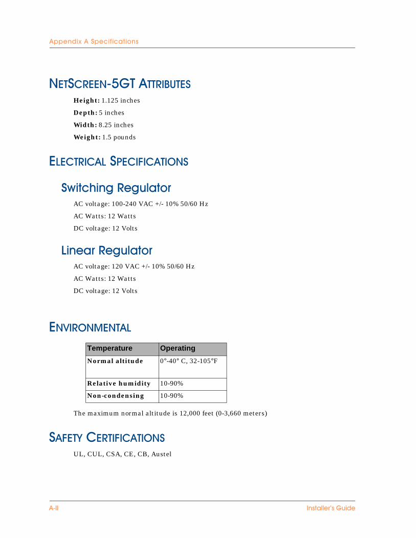
���������()������������Height: 1.125 inches
Depth: 5 inches
Width: 8.25 inches
Weight: 1.5 pounds
������������������ ��
�*���,����6���� ���AC voltage: 100-240 VAC +/- 10% 50/60 Hz
AC Watts: 12 Watts
DC voltage: 12 Volts
���� ��6���� ���AC voltage: 120 VAC +/- 10% 50/60 Hz
AC Watts: 12 Watts
DC voltage: 12 Volts
���� �������
The maximum normal altitude is 12,000 feet (0-3,660 meters)
�����*��������� ��UL, CUL, CSA, CE, CB, Austel
Temperature Operating
Normal altitude 0°-40° C, 32-105°F
Relative humidity 10-90%
Non-condensing 10-90%
'��� ���� ����=������
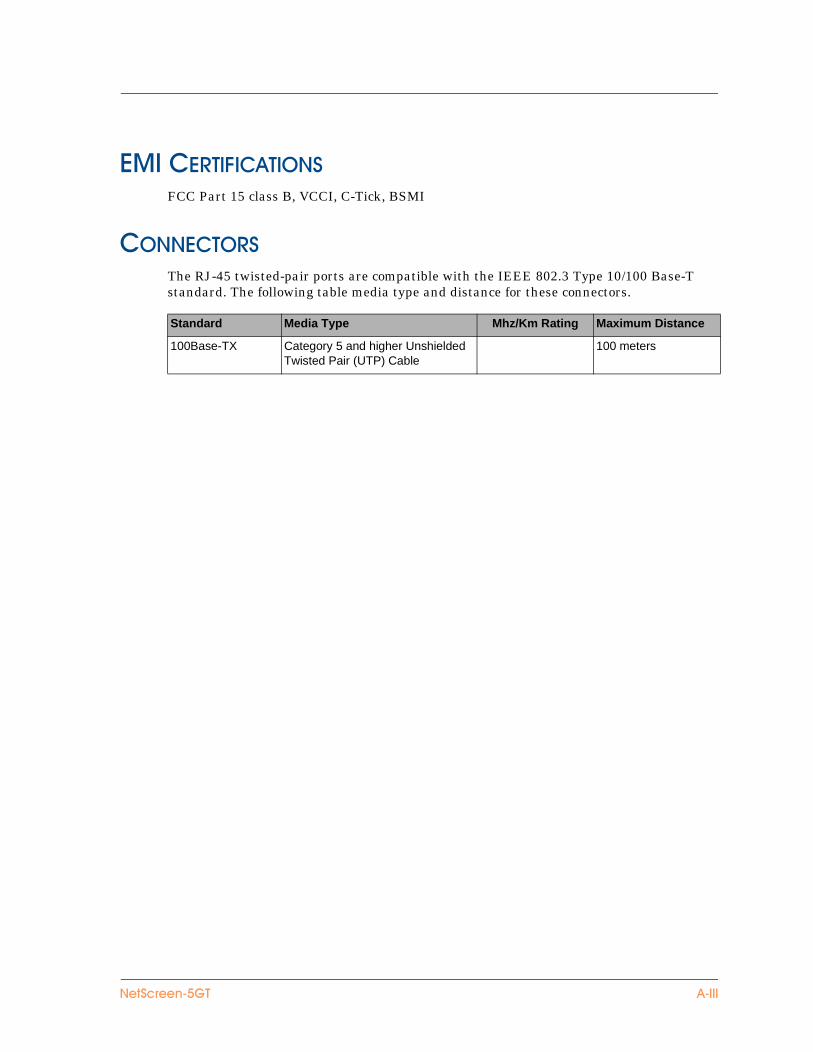
����������� ��FCC Part 15 class B, VCCI, C-Tick, BSMI
� ����� ��The RJ-45 twisted-pair ports are compatible with the IEEE 802.3 Type 10/100 Base-T standard. The following table media type and distance for these connectors.
Standard Media Type Mhz/Km Rating Maximum Distance
100Base-TX Category 5 and higher Unshielded Twisted Pair (UTP) Cable
100 meters
����������� '����

'&&����$�'��&������ �����
'��" ���� ����=������
�����$
����$'Accessing 15asset recovery 19
�changing login and password 12connecting, system to a router or modem 7connecting, system to LAN or workstation 7connecting, system to other devices 7
guide organization v
�IP address
system 15
�LED status 3link status LED 3login, changing 12
�NetScreen Publications ixNetScreen-5GT, connecting to a LAN orworkstation 7
NetScreen-5GT, connecting to a router ormodem 7NetScreen-5GT, connecting to other devices7NetScreen-5GT, port status LEDs 4NetScreen-5GT, system status LEDs 4
�password
forgetting 19password, changing 12port modes 13port status LEDs 4power LED 3
6reset 19
�status LED 3system IP address 15system status LEDs 4
�Transparent mode 10
����������� �>��

�����$
�>��� ���� ����=������