Embed Size (px)
Citation preview
Software Framework for Managing
Heterogeneity in Mobile Collaborative Systems
CARLOS D. CORREA & IVAN MARSICCenter for Advanced Information Processing (CAIP), Rutgers – The State University of New
Jersey, Piscataway, NJ 08854-8058, USA (E-mails: {cdcorrea, marsic}@caip.rutgers.edu)
Abstract. Heterogeneity in mobile computing devices and application scenarios complicatesthe development of collaborative software systems. Heterogeneity includes disparate com-puting and communication capabilities, differences in users’ needs and interests, and semantic
conflicts across different domains and representations. In this paper, we describe a softwareframework that supports mobile collaboration by managing several aspects of heterogeneity.Adopting graph as a common data structure for the application state representation enables usto develop a generic solution for handling the heterogeneities. The effect external forces, such
as resource constraints and diverging user interests, can be quantified and controlled asrelational and attribute heterogeneity of state graphs. When mapping the distributed replicasof the application state, the external forces inflict a loss of graph information, resulting in
many-to-one correspondences of graph elements. A key requirement for meaningful collab-oration is maintaining a consistent shared state across the collaborating sites. Our frameworkmakes the best of maximizing the state consistency, while accommodating the external force
constraints, primarily the efficient use of scarce system resources. Furthermore, we describe themobility aspects of our framework, mainly its extension to peer-to-peer scenarios and situa-tions of intermittent connectivity. We describe an implementation of our framework applied
to the interoperation of shared graphics editors across multiple platforms, where users are ableto share 2D and 3D virtual environments represented as XML documents. We also presentperformance results, namely resource efficiency and latency, which demonstrate its feasibilityfor mobile scenarios.
Key words: collaborative systems, consistency maintenance, content adaptation, mobilecomputing, scene simplification
1. Introduction
Computing platforms are rapidly becoming more heterogeneous, primarily interms of device capabilities: display characteristics, CPU speeds, memory,and network connectivity. Small portable devices, such as handheld com-puters, smart phones and wireless watches, are becoming popular means toaccess the Internet. Traditional application frameworks have concentratedon systems of similar machines. However, with heterogeneous devices pro-liferating, there is a need for applications that are tailored to the capabilities
Computer Supported Cooperative Work (2004) 13: 603–638 � Springer 2005
of their current computing and communications environment. Such tailoringresults in differences in data representations, GUI structures and behaviorswhen run on different platforms. There have been heterogeneous platformsand applications in the past, but what is new is ubiquitous connectivity thatallows them to access and share the same data and collaborate at the sametime.
Our work concerns the interoperation of collaborative applications so thatusers can equitably and efficiently employ heterogeneous computer devices.Some typical application scenarios for using diverse platforms include teamscollaborating on shared data, or pervasive computing, where the applicationstate is available anywhere and the user may at different times employ unlikedevices to access and edit the same document.
The application state comprises all the application’s data structures thatare relevant for the process of sharing. An example of application state iswhat is usually called scene graph in two-dimensional and three-dimensionalgraphics applications. It is a hierarchical description of scene objects, withpart-whole representation at different levels of abstraction. Other examplesinclude conceptual knowledge representation using relationships such asinheritance, spatial or temporal proximity, etc. There are many different datastructures, but in this work we focus on the graph data structure as acanonical representation, since it is the most common one and the resultshere can be relatively easily generalized to other data structures.
In mobile collaborative systems, the application state in several devicesoften needs to be reduced or simplified in order to accommodate for limitedresources. Furthermore, not all applications are available across multipleplatforms, and there is the need to interoperate a variety of heterogeneousapplications in order to support collaborative work. Unlike homogenoussystems, where replicas have a one-to-one correspondence between theirelements, the simplification of the application state results in many-to-onecorrespondences, where several elements from one replica might be con-tracted into a single element from another replica, usually running on adevice with lower computing capabilities. The many-to-one correspondence,otherwise known as surjective mapping between their application states,implies additional challenges for collaboration.
A key issue is maintaining consistent state across the applications runningat distributed sites. Without consistency guarantees, the application states atdifferent sites would diverge, in which case they could as well be considered asentirely disconnected from each other. The term ‘‘consistency’’ is used indifferent contexts. In this paper, consistency means the absence of logicalcontradictions between the replicated copies of a data object. Maintainingconsistent state of replicated clients in homogeneous systems is a well-researched problem, see e.g., (Birman, 1996; Sun and Chen, 2002), and is notaddressed here. However, in addition to the problems inherited from
CARLOS D. CORREA & IVAN MARSIC604

homogeneous collaborative applications, there are some problems specific toapplications with heterogeneous representations and the latter are the focusof this paper.
This paper, which is a revised and expanded version of (Correa andMarsic, 2003), presents a framework that manages several aspects of heter-ogeneity in collaborative systems: differences in user’s interest, semanticconflicts across different domains and representations, and disparate devicecapabilities. The key objective is maintaining consistent application statesbetween the participants. The framework, described in Section 3, is based ongraph mappings that can be tailored to the application needs using topo-logical transformations of the data structures, property mappings, and user-defined policies. Section 4 describes several applications of the framework,each of them aimed to solve a particular issue in heterogeneous systems. InSection 5 we describe performance results obtained in terms of resourceefficiency and response time. Finally, we present conclusions in Section 6.
2. Related work
To our best knowledge, there has been no other work on consistency incollaborative applications with many-to-one (lossy) mappings between thedata representations and with bi-directional interactions. We organize thereview of the related work in three groups:
• Semantic consistency maintenance in databases.• Simplification of structured representations by lossy ‘‘compression’’.• Collaborative systems that address some heterogeneity issues.
Consistency maintenance is a traditional problem in databases (Connollyet al., 1996). Databases are mostly concerned with the process view of con-sistency, in the sense of ordering and closure constraints on the propagationof write operations. Unlike this, our focus here is to ensure that differentrepresentations of the replicated state are not logically contradictory. Workon interoperating databases (e.g., Ceri and Widom, 1993; Bright et al., 1994;Sciore et al., 1994) concerns itself with mapping queries so the data can beaccessed from heterogeneous databases. However, it assumes that alldomains have exact (i.e., one-to-one) correspondence, and since our mainfocus is on representations with many-to-one correspondence, this work is oflimited applicability here.
The second related area, simplification of structured data to reduce theresource demand, has received a lot of attention in the literature. Simplifyingor ‘‘compressing’’ structured content is a common practice, analogous tosignal or image compression. Lossy simplification of structured contentranges from reducing the number of polygons of a 3D representation
SOFTWARE FRAMEWORK FOR MANAGING HETEROGENEITY 605
(Funkhouser and Sequin, 1993; Mason and Blake, 2001), through MPEG-4video compression (Moving Picture Experts Group, 2003), transcoding ofWeb content (Fox et al., 1998; Britton et al., 2001; Lum and Lau, 2002), totext summarization (Marcu, 2000; Mani, 2001). However, these all addressone-way content compression. We believe that there will arise the need forcollaboration and bi-directional exchange on documents compressed to dif-ferent degrees at different collaborating sites. This paper addresses the relatedissues.
The third related area are consistency and heterogeneity-support in col-laborative systems. The existing research in consistency is mainly interestedin ensuring that replicas are consistent after concurrent updates (Munson andDewan, 1996; Sun and Ellis, 1998). Although one aspect of our framework isthe maintenance of consistency of multiple representations with many-to-onecorrespondences, our work is not aimed to solve the concurrency problem,but rather it is designed to be used in combination with such methods. Ourframework abstracts user updates over the shared data as graph operations,which then can be handled by existing concurrency control methods toprovide data consistency between all replicas in a heterogeneous system.
One of the direct applications of our framework is the interoperation ofheterogeneous editors, particularly those dealing with multimedia andgraphics, given the availability of graph structures for the underlying datarepresentation. There are several research efforts in interoperating hetero-geneous collaborative systems, particularly groupware editors.
DistEdit (Knister and Prakash, 1990), for instance, is a groupware toolkitthat enables collaboration of users of disparate single-user editors. Theyevaluate their system with two text editors and target additional challenges incollaboration such as fault-tolerance. In this paper we also target the inter-operation of disparate single-user editors as an application scenario. Whiletheir work offers a mechanism for creating a correspondence between useroperations (or editor primitives), our work assumes representations withmany-to-one correspondence, which implies additional challenges.
Corona (Hall et al., 1996) addresses the problem of heterogeneity from theperspective of middleware support: in a collaborative scenario, different usersmay require different data subscription parameters, such as reliability,awareness information and scalability, which often result in a tradeoff. Forthis purpose, they built a middleware that supports two levels of services,which can be modified dynamically. Unlike Corona, our framework workson the application data level and works independently from the underlyingcommunication service or middleware. However, our framework also aims tosupport a variety of systems with disparate preferences, such as user-definedrules or resource capabilities.
The work of (Li and Rui, 2002) offers a solution to transparent sharing ofheterogeneous single-user applications, called intelligent collaboration trans-
CARLOS D. CORREA & IVAN MARSIC606
parency, which takes advantage of the particular application semantics andthe task at hand. Our framework also addresses the problem of maintainingthe application semantics in disparate applications. However, our focus is onthe representations with many-to-one correspondences. This assumption iskey for supporting heterogeneous applications in the presence of limitedresources and applications where a one-to-one semantic correspondence isnot always possible.
Recently, there has been interest in collaboration over multimedia appli-cations. One such effort is JASMINE (Shirmohammadi et al., 2003), whichallows users to share Java applications transparently. Like JASMINE, wehave used our framework for sharing Java-based multimedia applications,such as 2D and 3D editors. However, our primary objective is not to providetransparent collaboration. Our framework can be used to transparently shareapplications, as long as the user interaction can be intercepted and mappedinto graph operations, but in many occasions, as pointed out in the literature,multimedia applications exploit resources better when they are collaborationaware. An example of this is described in the evaluation section, where anapplication running on a mobile device adapts to the latency to betteraccommodate the resources, while providing interactivity to the user.
A recent effort by (De Lara et al., 2003) addresses the problem of repli-cation in the presence of multi-fidelity components, as applied to collabo-rative multimedia on mobile devices. Their work builds on top of existingreplication methods to account for data elements with partial fidelities, e.g.,images with varying resolution. Our framework also targets collaboration onresource-limited devices, and multi-fidelity components are supportedthrough property conversion functions as described later in Section 4.3. Akey difference is that our work also supports multiple fidelities at thetopology level, i.e., the application state at a thin client contains not onlysimplified data elements, but also a simplified structure from the originalapplication state. Since our work is independent from the replication algo-rithm, especially in relation to concurrency control, we believe that somemechanisms from their work may co-exist with our framework.
A recent work by Phan et al. (2004) addresses the problem of lossytranscoding in content-sharing and content-migration scenarios. They pro-pose a solution to transcode operations on shared objects (assuming aone-to-one correspondence), so that lossy information is not sent unneces-sarily from mobile devices to devices of higher capabilities, while maintainingthe semantics of the operation. Our paper is mainly concerned with theproblem of mapping the application state structure, and even though theapplication semantics are considered in our framework, data transcodingimplies additional challenges in the presence of many-to-one correspon-dences. This topic is being currently investigated by the authors.
SOFTWARE FRAMEWORK FOR MANAGING HETEROGENEITY 607
A key requirement in mobile systems is the support for disconnectedoperation. Wireless links often provide only intermittent connectivity, so it isdesirable to maintain a local state to enable the user to continue the workwhile disconnected, and to re-synchronize when the client gets opportunity toreconnect. Some initial results already exist (Mascolo et al., 2002; SyncML,2002), and our team is currently addressing this issue as well.
3. Consistency maintenance framework
The principal types of data are attribute data and relational data. Attributedata represent the properties, qualities, or characteristics of entities or sets. Inmany applications, attribute data is represented as a list of pairs (type, value),which is semantic information associated with an entity. Relational data relateone entity to another and cannot be reduced to the properties of individualentities themselves. Graph is suitable to represent both types of data in asingle data structure, and we assume that collaborative systems use graphdata structure to represent the shared information. An application caninternally use any data structure for application state representation, pro-vided that it externally presents a graph-based API to its state. Topologically,we can represent the attributes/properties of a vertex as children vertices,each child corresponding to a single property. A property vertex vi = (typei,valuei) is referred to as having a semantic value (typei, valuei). This topo-logical representation of properties is in line with the attribute representationin DOM (Document Object Model) trees (http://www.w3.org/DOM/).
We assume that the state graphs are acyclic. For a given graph G, let V(G)denote the vertex set and E(G) the edge set, so we can write G = (V, E). Wealso assume that there is relation that associates vertices with properties c:VfiA, so that any vertex v has at most one property a ˛ A associated with it.Heterogeneous state representation implies that graphs at some hosts aredifferent from those at others. The difference can be (Ceri and Widom, 1993):structural, implying different relational topologies of graphs, or semantic,implying different attributes/properties of corresponding entities.
We start by considering an architecture with a single server and a singleclient. The server maintains the complete application state as a graph GS,which we call super-graph since it contains all the information. The appli-cation state on the client, denoted as a graph GC, is typically less detailed, andit never contains more information than GS. We say that the client graph isan approximation of the server graph, obtained by a lossy mapping.
We define M ¼ {M, w,ˆ} as a mapping between a server graph GS and aclient graph GC, where M is a topological graph mapping, w is a set ofproperty transformation functions, and ˆ is a set of application-dependent
CARLOS D. CORREA & IVAN MARSIC608
and user-defined policies for resolving mapping ambiguities, described in thefollowing sections.
The above mappings are increasingly more specific to the individualrequirements of the clients. This means that while topological mappings canbe used in the great majority of collaborative systems, property mappings whave a more restricted applicability in certain domains, and policies ˆ areeven more specific to the application needs and the user interests.
3.1. TOPOLOGY MAPPINGS
Topological or structural mappings define the way the vertices and edges ofthe server graph GS are mapped to the client graph GC. Before defining thetopological mapping, let us review the concept of surjective mapping: Amapping M from a set A to a set B, denoted as M: AfiB, is said to besurjective if each element in B is mapped from some element in A. Note thatseveral elements in A may be mapped to the same element in B.
Let us first define a topological graph mapping M: GS fi GC. The domainofM is the graph G�S ¼ ðV�;E�Þ, such that V� � VðGSÞ and E� � EðGSÞ.M iscomposed of two surjective mappings MV: V*fiV(GC) and ME: E*fiE(GC).When defining a mapping M that simplifies a state graph, we can limit itsdomain G�S, so that for a vertex v˛V(GS), if v j2V� then v is not mapped to theclient graph at all. Similarly, for an edge e ˛ E(GS), if e ˇ E* then e is notmapped to the client graph. For the mapping itself, we allow only the fol-lowing three types of mapping (or their composition) for the purpose ofgraph simplification:
1. Identity of a vertex/edge. For any given vertex v˛V*, there is no vertexu˛V*, u „ v, such that MV(u) = MV(v), i.e., its mapping is unique.Similarly, for a given edge e˛E*, there is no edge e 2 E�, e 6¼ e, such thatMEðeÞ ¼MEðeÞ. Then v and e are said to be mapped via subgraphmapping.
2. Vertex contraction of two or more vertices into a single vertex, whereinternal edge(s) connecting them are removed. We denote this as follows:For v1; v2; . . . ; vn 2 V� when MVðv1Þ ¼MVðv2Þ ¼ � � � ¼MVðvnÞ ¼ w 2VðGCÞ.
3. Path merging: A chain of two or more edges is merged into a singleedge, and the internal vertices connecting them are removed. We denotethis as follows: If e1; e2; . . . ; en 2 E� are edges in a path p thenMEðe1Þ ¼MEðe2Þ ¼ � � � ¼MEðenÞ ¼ e 2 EðGCÞ. All internal vertices ofthe path p have degree 2.
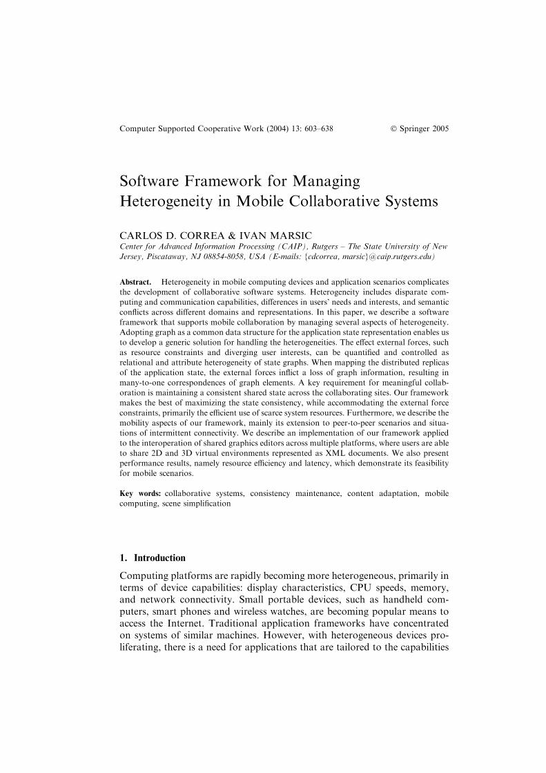
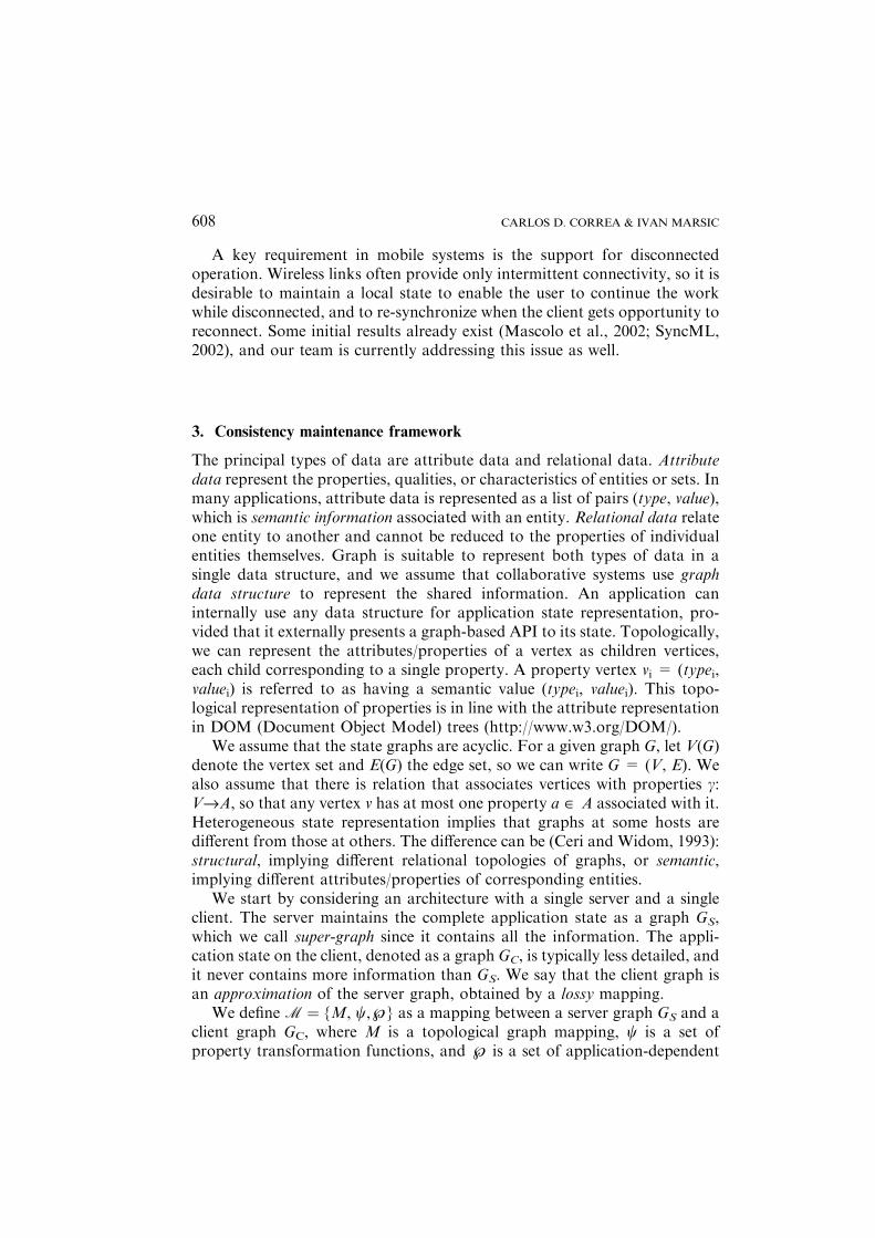
Figure 1 shows examples of graphs obtained by applying the above graphmappings. Figure 1(a) shows the effects of subgraph mapping: elements
SOFTWARE FRAMEWORK FOR MANAGING HETEROGENEITY 609
which are of interest to the client application are mapped 1:1 from thesupergraph, while the rest are not mapped at all. Similarly, this type ofmapping allows filtering of the application data so it can be transmittedefficiently to a variety of disparate applications. Vertex contraction, asillustrated in Figure 1(b) provides the basic mechanism for applications suchas simplification and summarization: an entire set of vertices can be mappedto a single vertex in the client graph, so that resources can be used efficiently,while maintaining some level of detail of the original data. Figure 1(c) showsan example of path merging. Since edges are often used for representinghierarchical relationships between data elements, path merging results in acontraction or abstraction of such hierarchical relationship, such as the chainof formatting tags in an HTML document.
The reason for the restriction to only these three is that these are the onlygraph mappings that preserve the local structure when removing vertices oredges. These constraints are provided in order to ensure that the client graph
Text1 Text2 Text1 Text2
Super-graph Client graph
Original Simplified
Panel
list item tag
font tag
paragraph
Panel
paragraph
desk
top drawer
pencil computer
desk (simplified)
computer
(a)
(b)
leg pencil
(c)
box box box cone cone cone box box box
Figure 1. Examples of lossy topology mappings: (a) Subgraph mapping; (b) Vertex contraction;
(c) Path merging.
CARLOS D. CORREA & IVAN MARSIC610
obtained by this lossy mapping retains similarity to the topology of the servergraph. This is stated as the following claim:
Proposition 1.The above three types of graph mapping are the only ones tohave the following properties:
(P1) Preservation of the hierarchical containment relationship between anypair of vertices in GC: If u, v are the end vertices of a pathp ¼ e1e2; . . . ; en; where e1; e2; . . . ; en 2 E(GS) (including edges, whichare paths of length 1), MEðe1Þ ¼MEðe2Þ ¼ � � � ¼MEðenÞ ¼ e0 thenMv(u) and Mv(v) are the end vertices of the edge e0:
(P2) Non-increasing degree of the end vertices of paths: No two paths whichare mapped to GC intersect, thus the degree of the end vertices of anedge in GC never exceeds the degree of the end vertices of the corre-sponding path in GS.
Proof. The proof is in two parts: (�) The graph mapping types defined abovesatisfy (P1) and (P2); and, (�) if a graph mapping satisfies (P1) and (P2),then it must be composed of the types defined above. The (�) part for (P1)follows as proof by contradiction. Let us assume that path p ¼ e1e2; . . . ; enwith ending vertices u and v is merged into a single edge e in GC and theending vertices of e are MV(u) and w¢ „ MV(v). Since MV is a surjectivemapping, w¢ has a pre-image w in GS. In such case w belongs to path p. If w isan internal vertex of p, then MV(w) does not exist (contradiction). Otherwise,it must be the end vertex of path p, in which case w = v and MV(w) = w¢ =MV(v). Thus (P1) follows. (P2) follows from the definition of edge mapping.If two paths intersect at an edge e, then e is mapped to two different edges inGC, which is a contradiction, since for any given mapping, a single graphelement in GS cannot have two images in GC.
The (�) part is as follows: From (P1) we derive that for any edge withending vertices u¢ and v¢ there must exist pre-images u, v in V* such thatMV(u)= u¢ and MV(v) = v¢. Since the mapping is surjective, it follows thatu¢ and v¢ have either one or many pre-images. It follows that vertices areeither mapped 1:1 or through vertex contraction. An important condition isthat if that is the case, if u and v are the pre-images of u¢ and v¢, then neither uor v are internal vertices of a path that satisfies (P1). This follows from thesame argument as below when considering the edge mapping.
Regarding edge mappings, it must be true that (P1) and (P2) imply thatedges can only be mapped through path merging. Let us consider aninternal vertex w of a path p: ufiv, such that p satisfies conditions (P1)and (P2). Three cases for w might result in a mapping different than pathmerging: (1) w is an internal vertex of path p¢ „ p. In such case, bothpaths clearly intersect at an edge incident to w. Since this contradicts (P2),it cannot be the case. (2) w is an end vertex of a path that intersects p.
SOFTWARE FRAMEWORK FOR MANAGING HETEROGENEITY 611
Clearly, by contradiction this cannot be the case. (3) w is an end vertex ofa path that does not intersect p. In such case, path p is not merged, but itmust be split into two paths ufiw and wfiv, which satisfy (P1). Since weassume that path p cannot be split (P1), then any internal vertex of a pathis inherently not mapped, and the edge mapping must then be product ofpath merging.
The proof that all internal vertices of a path that satisfies (P1) have degree2 follows using the same rationale as above. If any internal vertex w hasdegree greater than 2, then there must be an edge e ¼ ww¢ such that e 2 E�, w¢not in path p. In that case w must also be in V*, which results in the samecases as above. u
3.2. PROPERTY MAPPINGS
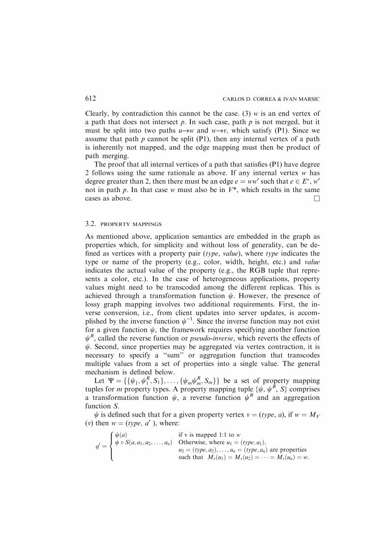
As mentioned above, application semantics are embedded in the graph asproperties which, for simplicity and without loss of generality, can be de-fined as vertices with a property pair (type, value), where type indicates thetype or name of the property (e.g., color, width, height, etc.) and valueindicates the actual value of the property (e.g., the RGB tuple that repre-sents a color, etc.). In the case of heterogeneous applications, propertyvalues might need to be transcoded among the different replicas. This isachieved through a transformation function w. However, the presence oflossy graph mapping involves two additional requirements. First, the in-verse conversion, i.e., from client updates into server updates, is accom-plished by the inverse function w)1. Since the inverse function may not existfor a given function w, the framework requires specifying another functionwR, called the reverse function or pseudo-inverse, which reverts the effects ofw. Second, since properties may be aggregated via vertex contraction, it isnecessary to specify a ‘‘sum’’ or aggregation function that transcodesmultiple values from a set of properties into a single value. The generalmechanism is defined below.
Let W ¼ ffw1;wR1 ;S1g; . . . ; fwmwR
m;Smgg be a set of property mappingtuples for m property types. A property mapping tuple {w, wR, S} comprisesa transformation function w, a reverse function wR and an aggregationfunction S.
w is defined such that for a given property vertex v ¼ (type, a), if w ¼MV
(v) then w ¼ (type, a¢ ), where:
a0 ¼
wðaÞ if v is mapped 1:1 to ww � Sða; a1; a2; . . . ; anÞ Otherwise, where u1 ¼ ðtype; a1Þ;
u2 ¼ ðtype; a2Þ; . . . ; un ¼ ðtype; anÞ are propertiessuch that Mvðu1Þ ¼Mvðu2Þ ¼ � � � ¼MvðunÞ ¼ w.
8>><
>>:
CARLOS D. CORREA & IVAN MARSIC612

To understand the necessity for an aggregation function S, let us considerthe scenario of interoperating graphics editors. Due to resource limita-tions, some elements in one editor might be grouped or contracted in theother editor. We want to define the property mapping for the bounding-box property. The bounding-box property is defined as (x0, y0, x1, y1),where (x0, y0) and (x1, y1) are the 2D coordinates of the corners of theminimal box that entirely covers a graphics element in the 2D editor. Ifboth 2D editors share the same coordinate system, w can be defined as theidentity function. However, for supporting contraction of elements of oneeditor into single elements of the other, we then define S as follows: for b1and b2 the bounding boxes of elements v1 and v2:
Sðb1; b2Þ ¼ ðminðb1�x0; b2�x0Þ; minðb1�y0; b2�y0Þ;maxðb1:x1; b2�x1Þ; maxðb1�y1; b2�y1ÞÞ:
For an example of a reverse function, consider the conversion between 2Dand 3D coordinates in graphics editors. The property position in the 3Ddomain, consists of a tuple (x,y,z). Conversion to the 2D domain can be donethrough a simple function:
Position2D�value ¼ wððx; y; zÞÞ ¼ ðx; yÞ:However, it is not possible to compute the inverse function deterministi-
cally. If the 2D application creates a vertex with property (Position, (x,y) ),this applies to infinite positions in the 3D environment along the z-axis. Thisis solved with a reverse function wR, such as:
Position3D�value ¼ wRððx; yÞÞ ¼ ðx; y; 0Þ:Property mappings for 3D to 2D coordinates may be more complex, since
they need to handle rotations and scales in addition to positions, and theymay depend on the coordinate systems of the ancestor vertices in the scenegraph.
3.3. APPLICATION-DEPENDENT AND USER-DEFINED POLICIES
Since the server-client mapping is not a one-to-one function, in some cases itis not possible to determine the inverse function for a given client operation.User-defined policies ˆ fill the gaps where topology and property mappingsare unable to make such a decision.
Let us consider the case where a group of server vertices v1, v2,…,vn iscontracted into a client vertex w. When the client adds an edge from w toanother vertex w¢, it may be necessary to add several edges from v1, v2,…,vn tosome other vertices at the server. The exact number of new edges generated atthe server is application-dependent and cannot be determined from the
SOFTWARE FRAMEWORK FOR MANAGING HETEROGENEITY 613
topology mapping alone. In such case, an application-dependant or a user-defined policy will determine the correct operation.
In our framework, this can be accomplished with the use of reversefunctions similar to those for property mappings. Thus, our framework alsodefines a reverse mapping functionMR
V : VðGCÞ !W� forW� �Q
VðGSÞ, theset of all possible sets of vertices in GS, and a reverse mappingMR
E : EðGCÞ ! P�, for P� �Q
EðGSÞ, the set of all possible edge sets in GS,
such that:
1. For a set V0 ¼ fv1; v2; . . . ; vng �Q
VðGSÞ, if MVðv1Þ ¼MVðv2Þ ¼ � � � ¼MVðvnÞ ¼ w, then MR
VðwÞ ¼W � V0.2. For a set E0 ¼ fe1; e2; . . . ; eng �
QEðGSÞ, if MEðe1Þ ¼MEðe2Þ ¼ � � � ¼
MEðenÞ ¼ e0, then MREðe0Þ ¼ F � E0.
3.4. FRAMEWORK OPERATION
Having defined the lossy mappings between the server and client graphs, wedescribe the functionality of the framework. The user can perform the fol-lowing graph operations:
1. Topological operations: add/remove a vertex or an edge.2. Property operations: set a property value, modify a property by applying
a function f to its value.
M
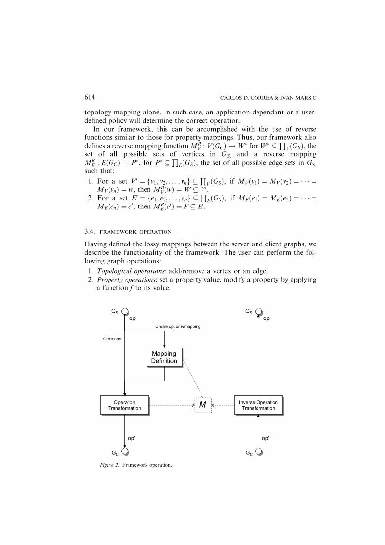
Figure 2. Framework operation.
CARLOS D. CORREA & IVAN MARSIC614
3. Application- and User-defined operations: combinations of the above, e.g.,copy/paste a subgraph can be defined in terms of vertex and edgeadditions.
For a given operation op performed on the server graph GS, the frameworkmust be able to determine a corresponding operation op¢ on the client graphGC, such that the resulting mapping still satisfies Proposition 1. For opera-tions that involve a creation (add vertex or edge), this is accomplished in twostages: First, the mapping of the newly created vertex or edge is defined;second, the operation is transformed into op¢, according to the mappingdefined in the first stage. For other operations, only the operation transfor-mation stage is performed (see Figure 2).
3.4.1. Mapping DefinitionOne of the greatest challenges in our framework is to define the initialmapping for the different elements in the collaborative system. The mappingdefinition can be of two types: direct- or indirect mapping definition. In thedirect definition, the application explicitly defines the mapping for each newlycreated vertex or set. An example of this is rule-based definition, explainedbelow. In the indirect definition, the mapping is generated indirectly as aresult of an automated process. An example of such generation is throughoptimization algorithms, whose result is the optimal scheduling of verticesand edges that maximizes a given objective function.
For direct mapping definition, it is necessary to check the consistency ofthe mapping, given that it might be possible that the rules produce con-tradicting mappings. We define mapping consistency as follows:
Definition 1.We say that mappingM= (MV,ME) is consistent ifMV andME
are surjective mappings that satisfy the Proposition 1.
The consistency checking is performed as follows: Let us define Mt =(MV
t, MEt) a tentative mapping as defined by the direct mapping generation,
which may contain inconsistencies. The following procedure removes theinconsistencies and produces the final mapping M = (MV, ME).
Procedure Process Tentative Mapping ()
1. Check for 1:1 vertex mappings:
For any vertex v, MtV (v) = w such that the relation is 1:1
If there is not a vertex w0 = MV (v), w0 „ w, then make MV(v) = w
Otherwise, Discard MtvðvÞ
2. Check for 1:1 edge mappings
For any edge e, MtEðeÞ ¼ e such that the relation is 1:1
If there is no edge e0 ¼MEðeÞ, e0 6¼ e, then make MEðeÞ ¼ eOtherwise, Discard Mt
EðeÞ
SOFTWARE FRAMEWORK FOR MANAGING HETEROGENEITY 615
3. Check for remaining vertex mappings (i.e., many-to-one mappings)
{Same as step 1, for any remaining vertex v such that MtV ðvÞ ¼ w
4. Check for many-to-one edge mappings
For edges e0 = (u, u1), e1 ¼ ðu1; u2Þ; . . . en ¼ ðun; vÞ, such that
MtEðe0Þ ¼Mt
Eðe1Þ ¼ � � � ¼MtEðenÞ ¼ e then
If the following conditions are true:{
e0e1,…,en is a path of GS
MV(u1), MV (u2), … , MV (un) are not defined (i.e., internal vertices are not mapped)
MV (u) „ MV (v) if they are defined (i.e., the endpoints of the path are distinct)
}then: Set MEðe0Þ ¼MEðe1Þ ¼ � � � ¼MEðenÞ ¼ e, and MV(u) = u¢, MV(v) = v¢ if notdefined.
SetMV(u1) =MV(u2) = � � �=MV(un) = Ø (empty vertex), or mark as explicitly non-
mapped in order to test for future inconsistencies.
{Otherwise, discard MEt(e0), ME
t(e1),…, MEt(en)
5. Add edge-induced mappings
For every edge e = uv in GS, such that MV(u) and MV(v) exist, MV(u) „ MV(v), then
{make ME(e) = MV(u) MV (v)
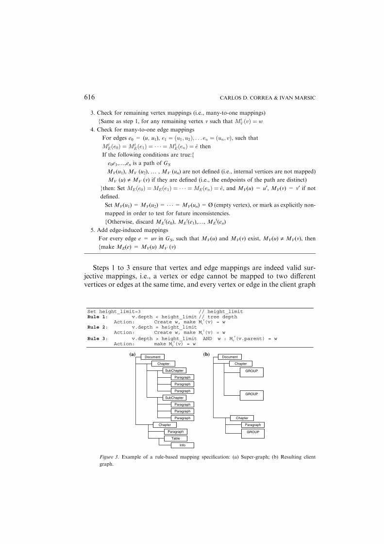
Steps 1 to 3 ensure that vertex and edge mappings are indeed valid sur-jective mappings, i.e., a vertex or edge cannot be mapped to two differentvertices or edges at the same time, and every vertex or edge in the client graph
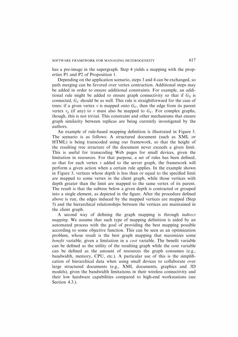
Set height_limit=3 // height_limit Rule 1: v.depth < height_limit // tree depth
Action: Create w, make MV
T(v) = w Rule 2: v.depth = height_limit
Action: Create w, make MV
T(v) = w Rule 3: v.depth > height_limit AND w : MV
T(v.parent) = w Action: make MV
T(v) = w
Document
Chapter
SubChapter
Paragraph
Paragraph
Paragraph
SubChapter
Paragraph
Paragraph
Paragraph
Chapter
Paragraph
Table
Info
Document
Chapter
GROUP
GROUP
Chapter
Paragraph
GROUP
(a) (b)
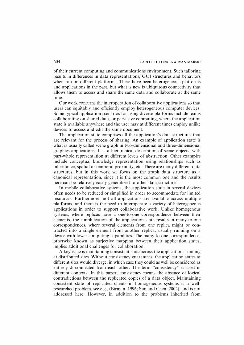
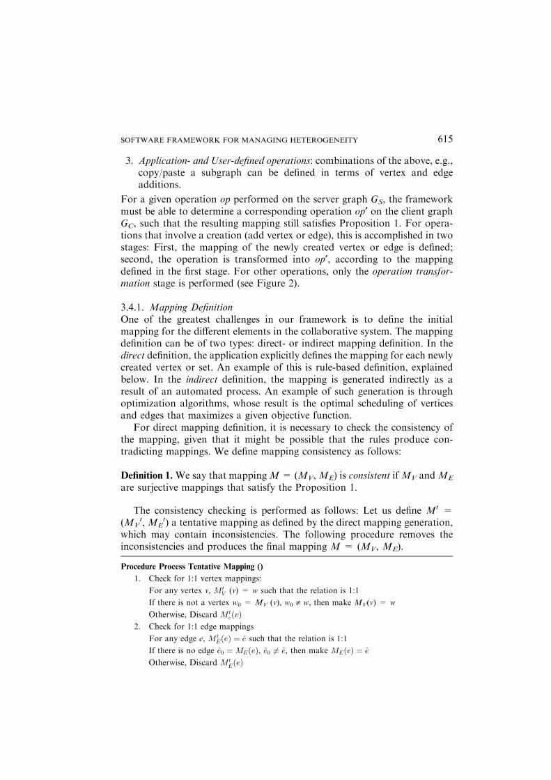
Figure 3. Example of a rule-based mapping specification: (a) Super-graph; (b) Resulting client
graph.
CARLOS D. CORREA & IVAN MARSIC616
has a pre-image in the supergraph. Step 4 yields a mapping with the prop-erties P1 and P2 of Proposition 1.
Depending on the application scenario, steps 3 and 4 can be exchanged, sopath merging can be favored over vertex contraction. Additional steps maybe added in order to ensure additional constraints. For example, an addi-tional rule might be added to ensure graph connectivity so that if GS isconnected, GC should be as well. This rule is straightforward for the case oftrees: if a given vertex v is mapped onto GC, then the edge from its parentvertex vp (if any) to v must also be mapped to GC. For complex graphs,though, this is not trivial. This constraint and other mechanisms that ensuregraph similarity between replicas are being currently investigated by theauthors.
An example of rule-based mapping definition is illustrated in Figure 3.The scenario is as follows: A structured document (such as XML orHTML) is being transcoded using our framework, so that the height ofthe resulting tree structure of the document never exceeds a given limit.This is useful for transcoding Web pages for small devices, given thelimitation in resources. For that purpose, a set of rules has been defined,so that for each vertex v added to the server graph, the framework willperform a given action when a certain rule applies. In the example shownin Figure 3, vertices whose depth is less than or equal to the specified limitare mapped to some vertex in the client graph, while those vertices withdepth greater than the limit are mapped to the same vertex of its parent.The result is that the subtree below a given depth is contracted or groupedinto a single element, as depicted in the figure. After the procedure definedabove is run, the edges induced by the mapped vertices are mapped (Step5) and the hierarchical relationships between the vertices are maintained inthe client graph.
A second way of defining the graph mapping is through indirectmapping. We assume that such type of mapping definition is aided by anautomated process with the goal of providing the best mapping possibleaccording to some objective function. This can be seen as an optimizationproblem, whose result is the best graph mapping that maximizes somebenefit variable, given a limitation in a cost variable. The benefit variablecan be defined as the utility of the resulting graph while the cost variablecan be defined as the amount of resources the graph consumes (e.g.,bandwidth, memory, CPU, etc.). A particular use of this is the simplifi-cation of hierarchical data when using small devices to collaborate overlarge structured documents (e.g., XML documents, graphics and 3Dmodels), given the bandwidth limitations in their wireless connectivity andtheir low hardware capabilities compared to high-end workstations (seeSection 4.3.).
SOFTWARE FRAMEWORK FOR MANAGING HETEROGENEITY 617
In most of the cases, the mapping definition obtained by optimizationis guaranteed to be consistent. This is because the optimal solution mustsatisfy the optimization problem constraints, which should be posed so toproduce only the mapping types of Proposition 1. However, if the opti-mization problem is not carefully defined it may result in inconsistentmappings, in which case the procedure ProcessTentativeMapping definedabove must be executed. (Clearly, if some mappings are discarded theresulting mapping might not be optimal).
We have seen that mapping definition through rule-based mapping canbe done on a per-vertex (per-edge) basis, with a simple algorithm todiscard those cases that result in inconsistencies. The result is a very fastmapping and low server overhead for a set of operations. On the otherhand, mapping definition through optimization must be performed over aset of vertices and edges (usually an entire subgraph), which considerablyincreases the server overhead. However, graph mapping obtained byoptimization is guaranteed to satisfy a given cost constraint and maximizea given benefit metric, unlike the rule-based mapping which only works ina best-effort manner. As already mentioned, this has direct use for inter-operating applications on a wide range of platforms and devices, whereresources are scarce and the need for high-quality information is imper-ative. In Section 5.1 we present performance results of comparing the twostrategies for mapping generation, which illustrates this tradeoff.
3.4.2. Operation TransformationThe goal of the operation transformation module is to convert a graphoperation op performed in GS into a graph operation, if any, op¢ to beperformed in GC, such that both graphs remain consistent in relation totheir mapping. In our framework, we define consistency in relation to agraph mapping M as follows:
Definition 2. We say GC is consistent with GS with respect to mapping M if Mis consistent (see Definition 1).
The algorithm for producing op¢ given a graph operation op in GS dependson whether op is an addition or deletion of a vertex or edge, as follows:
A formal proof that the algorithm results in a consistent mapping isout of the scope of this paper and details can be found in (Marsic et al.,2002). It suffices to know that the algorithm is consistent with the types ofmapping defined previously, as follows:
If op is: add vertex v to GS:
Find w = MV(v)
If w = MV(v) is unique and w „ B then op¢ = add vertex w to GC
Otherwise op¢ = noop (No operation)
If op is: add edge e = uv to GS:
CARLOS D. CORREA & IVAN MARSIC618

Find e = ME(e) = MV(u) MV(v) (given that it must be consistent from mapping
definition)
If there is no e¢ „ e, such that ME(e¢) = MV(u) MV(v) then op¢ = add edge e to GC
else op¢ = noop
If op is: remove vertex v from GS
Find w = MV(v)
If there is no v¢„ v such that MV(v¢) = w then op¢ = remove vertex w from GC
else op¢ = noop
If op is: remove edge e= uv from GS
Find e = ME(e)
If e exists, then op¢ = remove edge e from GC
else op¢ = noop
For 1:1 mapping, it is clear that an operation in GS is mapped into anidentical operation in GC, given that in such a case the vertex or edgemapping is unique.For vertex contraction, when adding a vertex that belongs to a group ofvertices, only a new vertex will be added to GC for the first vertexencountered (since no other mapping has been defined for the set). For therest, the transformation results in noop since the vertex already exists inGC. Similarly, when removing a vertex, only the vertex will be removedfrom GC when the last vertex of the group has been removed.For path merging, removing an internal vertex results in noop. Althougha result may be path disconnection, this actually occurs because it trig-gers the removal of its incident edges. It can be seen from the algorithmthat an edge removal in GS always implies an edge removal in GC evenfor the case of paths, since removing a single edge from a path results ina disconnection of the end vertices. Note that a more sophisticated wayof handling path disconnection is to split a given path p into two paths p1and p2 and include the ending vertices of the removed edge in GC. Thiscan be accomplished by feeding this sequence of operations into ourframework.
Note that all operations imply finding the mapping of the vertex or edge toGC. If no mapping is found, the result is noop.
3.4.3. Inverse Operation TransformationOperations may also be initiated by the client application. In such case,the goal of the inverse operation transformation is to find an operation opto be performed in GS, given an operation op¢ in GC. Since the graphmapping is inherently lossy, it is not possible to find the inverse trans-formation deterministically for all elements in GC. In such case, we make
SOFTWARE FRAMEWORK FOR MANAGING HETEROGENEITY 619
use of the reverse mapping or pseudo-inverse defined in Section 3.3 asfollows:
If op¢ is: Add vertex w to GC:
It is assumed to be mapped 1:1, in order to ensure the surjective mapping. Then we
create a vertex v in GS, and make MV(v) = w
If op¢ is: Remove vertex w from GC:
op¢ = remove v = MV-1(w), if MV
-1(w) exists
remove all vertices v ˛ V = MVR(w), otherwise
If op¢ is: Add edge e¢ = u¢v¢ to GC
Let u = MV-1(u¢) if MV
-1(u¢) existsand U = MV
R(u¢) otherwiseLet v = MV
-1(v¢), if MV-1(v¢) exists
and V = MVR(v¢) otherwise
Then op¢ is one of the following, depending on the result of the previous two conditions
(the combinations of obtained inverse and reverse mappings, u, U, v and V)
op¢ = add edge uv to GS
add edge ui v for all ui ˛ U to GS
add edge u vj for all vj ˛ V to GS
add edge ui vj for all ui ˛ U and all vj ˛ V to GS
Map added edges to e¢If op¢ is: Remove edge e¢ = u¢ v¢ from GC
op¢ = remove e = M�1E ðe0Þ, if M�1
E ðe0Þ existsremove all edges e ˛ E = ME
R(e¢), otherwise
3.4.4. Operation Transformation for PropertiesTransformation of property operations involves the transcoding of propertyvalues so that the result is consistent in both client and server according to theapplication semantics. We consider two property operations: setting a newvalue to a given property, and update of a property by applying an operation fto its value. Note that the latter might be reduced to the former by setting avalue to the result of the operation f. However, this may not be resource-efficient in all the cases and it might result in storing lossy information whengenerated from the client graph. Solutions for the case of 1:1 mappings arereported in (Phan et al., 2004), and we are currently investigating its general-ization to the many-to-one mapping scenario.
3.5. EXTENSION TO OTHER ARCHITECTURES
The framework can be extended to other network architectures. Here weconsider the case of multiple servers and clients, organized in a hierarchy of
CARLOS D. CORREA & IVAN MARSIC620
hosts, or in a peer-to-peer (P2P) fashion. The following sections show that,although our framework applies to the case of a hierarchy of servers andclients, the general case does not apply to the P2P scenario. We define a set ofconstraints to our mapping definition that make the P2P case a feasiblecollaborative scenario.
3.5.3. Multiple Servers and Clients
Proposition 2. The graph mapping types in Proposition 1 are transitive asfollows. If the mappingsM1: G1fiG2 andM2: G2fiG3 between the graphs G1,G2, and G3 satisfy Proposition 1, then there exists a mapping M3: G1 fi G3
which also satisfies Proposition 1.
Proof. Let M1 = (M1V, M1E) and M2 = (M2V, M2E) be two graph mappings.M1V and M2V are surjective vertex mappings, and M1E and M2E are sur-jective edge mappings. It follows that M3V = M1V o M2V and M3E = M1E oM2E are surjective mappings as well. Then, we can define M3 = (M3V, M3E)as a mapping between graphs G1 and G3. From this, condition (P1) follows: Ifu and v are the end vertices of a path p ¼ p1; p2 . . . ; pn in G1, thenM1V(u) andM1V(v) are the end vertices of a path e;e2; . . . ; en in G2, such that the edges inp1 are mapped to e1, those in p2 to e2, etc. In turn, M2V(M1V(u)) andM2V(M1V(v)) are the end vertices of an edge e¢ in G3 such that e1; e2; . . . ; enare mapped to e¢, from condition (P1) for mapping M2. Then, it follows thatM3 satisfies (P1).
G1 G2
GS
G1 G2
GS
M1c M2c
GV
G1 G2
(a)
(b)
(c)
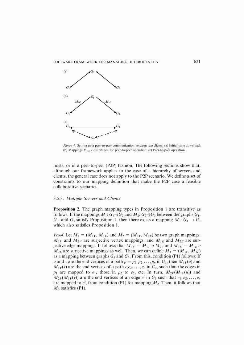
Figure 4. Setting up a peer-to-peer communication between two clients. (a) Initial state download;
(b) Mappings M<i>c distributed for peer-to-peer operation; (c) Peer-to-peer operation.
SOFTWARE FRAMEWORK FOR MANAGING HETEROGENEITY 621
It is clear that if paths in G1 which are mapped to G2 do not intersect andpaths in G2 which are mapped to G3 do not intersect, then it must be the casethat paths in G1 which are mapped to G3 do not intersect either. Thus, M3
satisfies (P2). The proposition follows. (Proposition 2 has an important implication: The framework can be ex-
tended from the case of a single server and client to the case of a hierarchy ofservers and clients. In such case, there is a supergraph, containing the mostdetailed and complete version of the application state, which are mapped in alossy manner to a set of less detailed server graphs, which in turn are mappedto another set of servers or to a group of clients. This hierarchy of servers andclients provides a scalable solution to the case of multiple heterogeneousclients. Clients that have similar mapping preferences can be aggregatedunder the same server. A drawback of this approach is that the graphmappings are inherently lossy, so that the graphs of the hosts at the bottomof different branches in the hierarchy might have diverged entirely due to thelossy mappings. This diminishes their possibilities for effective collaborativework. An alternative to such hierarchy is to interoperate the clients directly ina P2P fashion, as described in the next section.
3.5.2. Peer-to-Peer CollaborationLet us define M1: GS fi G1 and M2: GS fi G2 as two graph mappings from aserver graphGS to client graphsG1 andG2, respectively, which are consistent asper Definition 2.We define a peermappingM12:G1fiG2 as amapping betweentwo client graphs that were generated from a common server graph GS.
Definition 3. The mapping M12: G1 fi G2 is peer-consistent if transitivityholds forM1 andM2 as follows: For any v ˛ V2* (where V2* is the domain ofM2V) if v ˛ V1* then M2V(v) = M12V (M1V(v)) (similarly for edge mappings).This definition has a simple rationale. If an update is performed on a given
element in the super graph, the corresponding element in G2 should be thesame if it is mapped directly from GS, or if it is mapped from GS to G1 andthen mapped from G1 to G2.
Proposition 3. Given M1: GS fi G1 and M2: GS fi G2 two graph mappings, itis not always possible to find peer-consistent mappingsM12: G1 fi G2 orM21:G2 fi G1.
Proof. We provide a counter-example as follows. Let us consider M1V(u1) ¼M1V(u2) ¼ w1 and M1V(u3) ¼ w2, and M2V(u1) ¼ v1 and M2V(u2) ¼M2V(u3) ¼ v2, where u1, u2 and u3 are distinct vertices of GS, w1 and w2 aredistinct vertices of G1, and v1 and v2 are distinct vertices of G2. Let us try todefine M12V. If M12V(w1) ¼ v1, then M12V(M1V (u2)) ¼M12V(w1) ¼ v1 butM2V(u2) ¼ v2 „ v1. However, if we make M12V(w1) ¼ v2, then M12V
CARLOS D. CORREA & IVAN MARSIC622
(M1V(u1)) ¼M12V(w1) ¼ v2, but M2V(u1) ¼ v1 „ v2, i.e., it is not possible todefine such consistent mapping M12V. A similar case occurs when trying tofind M21V. In general, when paths or vertex sets of one mapping intersectwith those in the other mapping, but neither of them is a subset of the other,it is not possible to find a peer-consistent mapping.
The implication is that it is not possible to develop a general solution forthe P2P architecture. One solution to this problem is to modify one of theclient graphs, say G1, and convert it into G1¢, so that G1¢ is the minimalsupergraph of G1 such that a peer-consistent mapping G1¢ fi G2 exists. In theworst case, however, G1¢ happens to be the supergraph (GS), in which case theproblem is reduced to the original client-server case. This approach has nopractical validity in most of the scenarios since the client graph G1 wasdefined as a simplified version of GS given the limited resources, and makingit isomorphic to GS may not be physically possible.
Here we present another solution, which restricts the graph mapping tovertex contractions. These constraints are reasonable in a wide range ofapplications mentioned above, which use techniques such as summarization,abstraction or simplification of hierarchical structures, to adapt to the limitedsystem resources.
Let us define a partition P of V*. All vertices in the same member of P,which is a subset of V*, are mapped to the same vertex in the client graph.Then, we can express the graph mapping of client graphs Gi in terms of theirsubset and partition (Vi, Pi). We introduce the following constraints to thegraph mapping:
(B1) The mapping of the edges is induced by the mapping of vertices.(B2) Let (V1, P1) and (V2, P2) be subsets and partitions that define two
client graphs. Let U1 be a member of P1 and U2 a member of P2.Then, either U1 \ V2 and U2 \ V1 are disjoint, or one is a subset ofthe other.
From these constraints we see that any vertex set in one client graph iseither not mapped in any form, or contracted in a single vertex of the othergraph (since their original partitions in the supergraph are one a subset of theother). However, since some elements in one graph may not have a corre-sponding element in the other and vice versa, which violates the surjectivemapping assumption, we define the client graph mappings through a virtualserver graph GV. This means that operations from G1 are locally transformedto operations in GV (through the required mapping inverse) and thentransformed to operations in G2, and vice versa.
The scenario for setting up a P2P communication is depicted in Figure 4and works as follows. Initially, two clients are connected to a shared server atleast for the time to download the documents to collaborate on, Figure 4(a).When both clients are interested in setting a P2P connection, the mapping
SOFTWARE FRAMEWORK FOR MANAGING HETEROGENEITY 623
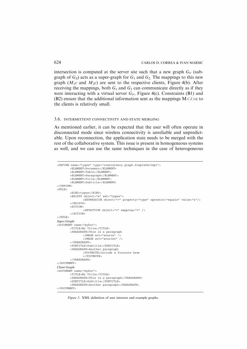
intersection is computed at the server site such that a new graph GV (sub-graph of GS) acts as a super-graph for G1 and G2. The mappings to this newgraph (M1c and M2c) are sent to the respective clients, Figure 4(b). Afterreceiving the mappings, both G1 and G2 can communicate directly as if theywere interacting with a virtual server GV, Figure 4(c). Constraints (B1) and(B2) ensure that the additional information sent as the mappings M< i>c tothe clients is relatively small.
3.6. INTERMITTENT CONNECTIVITY AND STATE MERGING
As mentioned earlier, it can be expected that the user will often operate indisconnected mode since wireless connectivity is unreliable and unpredict-able. Upon reconnection, the application state needs to be merged with therest of the collaborative system. This issue is present in homogeneous systemsas well, and we can use the same techniques in the case of heterogeneous
<DEFINE name="types" type="consistency.graph.SimpleSetImpl"><ELEMENT>Document</ELEMENT><ELEMENT>Table</ELEMENT><ELEMENT>Paragraph</ELEMENT><ELEMENT>Title</ELEMENT><ELEMENT>Subtitle</ELEMENT>
</DEFINE><RULE>
<BIND>types</BIND><EXISTS object="x" set="types">
<EXPRESSION object="v" property="type" operator="equals" value="x"/></EXISTS><ACTION>
<SETACTION object="v" mapping="v" /></ACTION>
</RULE>
Super-Graph:<DOCUMENT name="myDoc">
<TITLE>My Title</TITLE><PARAGRAPH>This is a paragraph
<IMAGE src="source" /><IMAGE src="source2" />
</PARAGRAPH><SUBTITLE>Subtitle</SUBTITLE><PARAGRAPH>Another paragraph
<FOOTNOTE>Include a footnote here</FOOTNOTE>
</PARAGRAPH></DOCUMENT>
Client Graph:<DOCUMENT name="myDoc">
<TITLE>My Title</TITLE><PARAGRAPH>This is a paragraph</PARAGRAPH><SUBTITLE>Subtitle</SUBTITLE><PARAGRAPH>Another paragraph</PARAGRAPH>
</DOCUMENT>
Figure 5. XML definition of user interests and example graphs.
CARLOS D. CORREA & IVAN MARSIC624
representations. Some recent systems are specifically targeted for statemerging in mobile applications (Mascolo et al., 2002; SyncML, 2002), butthey assume homogeneous application states.
The latecomer support is related to state merging. It is interesting to noticethat the same mapping specification for the same computing platform mayproduce different graphs on different clients. For example, an automatedmapping at time t produces a graph G1(t) for Client 1. As the users interactwith the system, the graph at t+N will be G1(t+N). If a Client 2 with thesame characteristics as Client 1 joins the session at t+N, the automatedmapping will produce for Client 2 G2(t+N) „ G1(t+N). This is since theautomated mapping tries to fit the maximum number of graph elements tothe available resources, whereas mappings individual graph operations fol-low different rules. However, this difference presents no problem for thealgorithm’s correct functioning.
3.7. STRENGTHS AND LIMITATIONS
The framework can be applied to the great majority of the collaborative sys-tems, where the graph is a common data structure. We provide a genericsolution to the interoperation of disparate applications by dividing the map-ping in the three types described in Section 3.1. The basic requirement for ourframework is the use of a directed graph as the underlying data structure forapplication state representation.
A key feature of the framework is that it provides consistent applicationstates between the participants of the collaborative system. Here, consistencymeans the absence of logical contradictions between the replicated copies of adata object. Consistency is maintained through the preservation of the graphmapping conditions for any given graph operation. It is important to note thatthis concept of consistency is different from data integrity under concurrent
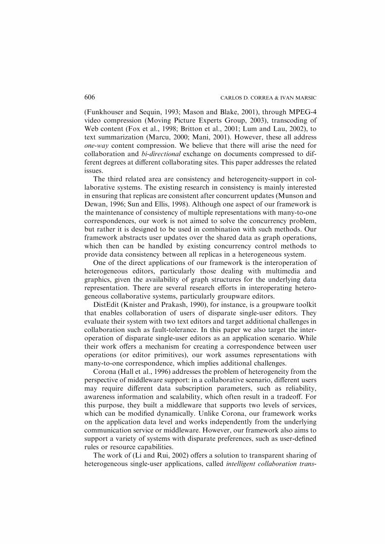
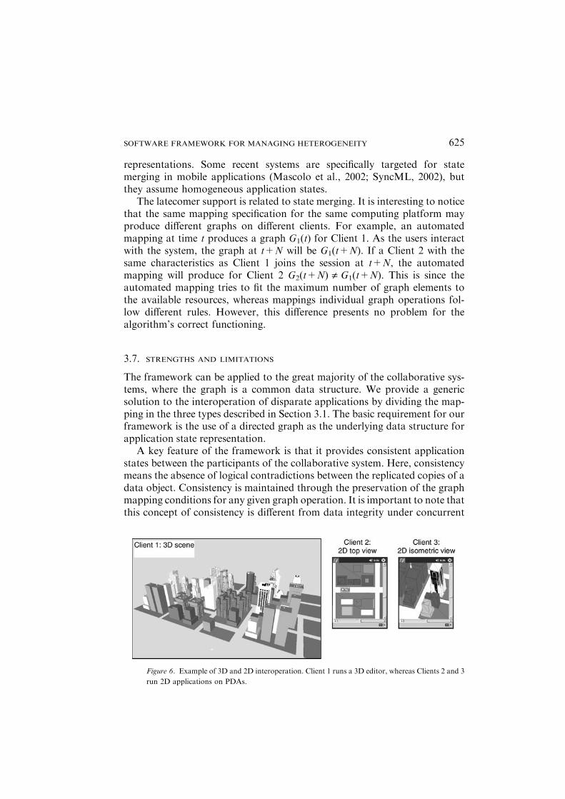
Figure 6. Example of 3D and 2D interoperation. Client 1 runs a 3D editor, whereas Clients 2 and 3
run 2D applications on PDAs.
SOFTWARE FRAMEWORK FOR MANAGING HETEROGENEITY 625
updates (Birman, 1996; Sun and Chen, 2002), which is a necessary requirementof most collaborative systems. Our framework is complementary with tradi-tional concurrency control mechanisms and can coexist with them since we donot impose a particular method for implementing graph operations.
In addition, the framework can be used to meet the constraints of a par-ticular system, with the use of property conversion functions and policies, andthe combination of such elements can be used to solve different challenges inheterogeneous systems. Section 4 describes example scenarios of how theframework could be used in collaborative applications.
One of the limitations of our framework is the key assumption regarding thenature of the underlying data structure. For collaborative environments thatshare structured data, the graph data structure may not be the most efficientdata type for all purposes, and some applications may suffer performancepenalty due to fixing the shared document structure. For example, a spread-sheet can be more efficiently represented as a multidimensional array. Theperformance of a graph-based spreadsheet may degenerate for a large docu-ment. However, we believe that such cases would appear relatively rarely inpractice and the gains from having a general solution far outweigh the draw-backs. Also, as already pointed out, the applicationmay use any data structureas long as it provides a graph-based API for application state access. In addi-tion, it appears that most future applications will exchange structured data asXML documents, which are trees – a subtype of a graph.
For the applications that work with or include non-structured elements,such as video and sound, one alternative is to use a meta-representation thatcanbedefined in a graph.For instance, a hierarchical descriptionof a video thatreflects the internal structure of scenes, shots and frames. One example of this isMPEG-4 data representation (Moving Picture Expert Group).
Another limitation is the requirement of the super-graph as a centralstructure, which implies client-server architecture. Section 3.5 discusses thepeer-to-peer architecture, where each client has a different application state andno client has all the information as to be defined as super-graph.We found thatit is not possible to solve efficiently the case of peer-to-peer communication inthe case of many-to-one mappings for the generic model. However, this limi-tation is not specific to graph representations – it is inherent to any heteroge-neous collaboration with lossy mappings between the states, regardless of thedata structure used for application state representation.
4. Example application scenarios
We have used the framework in several example scenarios of interoperating2D and 3D graphical editors, each of them exploiting different aspects of thearchitecture. The most significant ones are described in what follows.
CARLOS D. CORREA & IVAN MARSIC626

4.1. INTEREST MANAGEMENT AND FILTERING
One dimension of heterogeneity is defined by the user’s interest. Collabora-tive users may have a different assessment of the information usefulness,depending on the context, user’s role, personal preferences, etc., so they maywant to subscribe to different types of information.
In our framework, user interest is defined as production rules. Figure 5shows an XML-based rule specification for interest subscription based on thedata type. The XML definition allows the user to specify graph mapping as aset of rules by using predicate sentences and a set of actions for tentativemapping of each vertex. In the example shown, only those elements which fallinto some of the desired categories (i.e., Document, Table, Paragraph, Title,and Subtitle) are mapped to the client graph. Note that the identity mappingis defined for those vertices, meaning that they are mapped directly to theclient graph and no property conversion is needed. After the document iscreated, the system propagates only the updates related to the objects ofinterest, and all other updates do not reach the user.
4.2. SEMANTIC MAPPING FOR APPLICATIONS ACROSS MULTIPLE DOMAINS
Another dimension of heterogeneity is the semantic differences between theinformation representations. These may result from tailoring the applicationto unlike computing platforms or from interoperating existing applications
Figure 7. Example of optimal simplification: (a) Scene graph with (benefit, resource) pairs; (b)
Complete scene; (c) Simplified scene for max resources ¼ 5: (d) Shared navigation of a city model
on a mobile device.
SOFTWARE FRAMEWORK FOR MANAGING HETEROGENEITY 627
with different state representations. Our framework solves this kind ofproblems through property mappings. We have employed the framework tointeroperate 3D and 2D collaborative virtual worlds, where the users canmanipulate and edit the objects (Figure 6). In a typical scenario, a participantusing the 2D application only sees a planar view of a 3D model. Although theuser perceives the resulting images as flattened 3D models, the applicationitself is only aware of 2D primitives. In this scenario our framework is em-ployed as follows:
• If no resource limitations exist, the topology mapping between the graphsis defined as a 1:1 mapping of vertices and edges. Sometimes, though,certain vertices do not need to be mapped to the client graph, namelythose that are not visible from the current 2D perspective or that arecompletely occluded. That is, our framework is aided by a visibility-culling algorithm to define the vertex mapping.
• Property conversion functions w are used extensively to match thesemantics of the 3D editor (naming conventions, coordinate systems) tothe semantics of the 2D editor.
• Pseudo-inverse operations are also used extensively to allow bi-direc-tional interaction. Updates in the 2D editor are inherently ambiguouswhen mapped back to the 3D editor. These reverse operations are
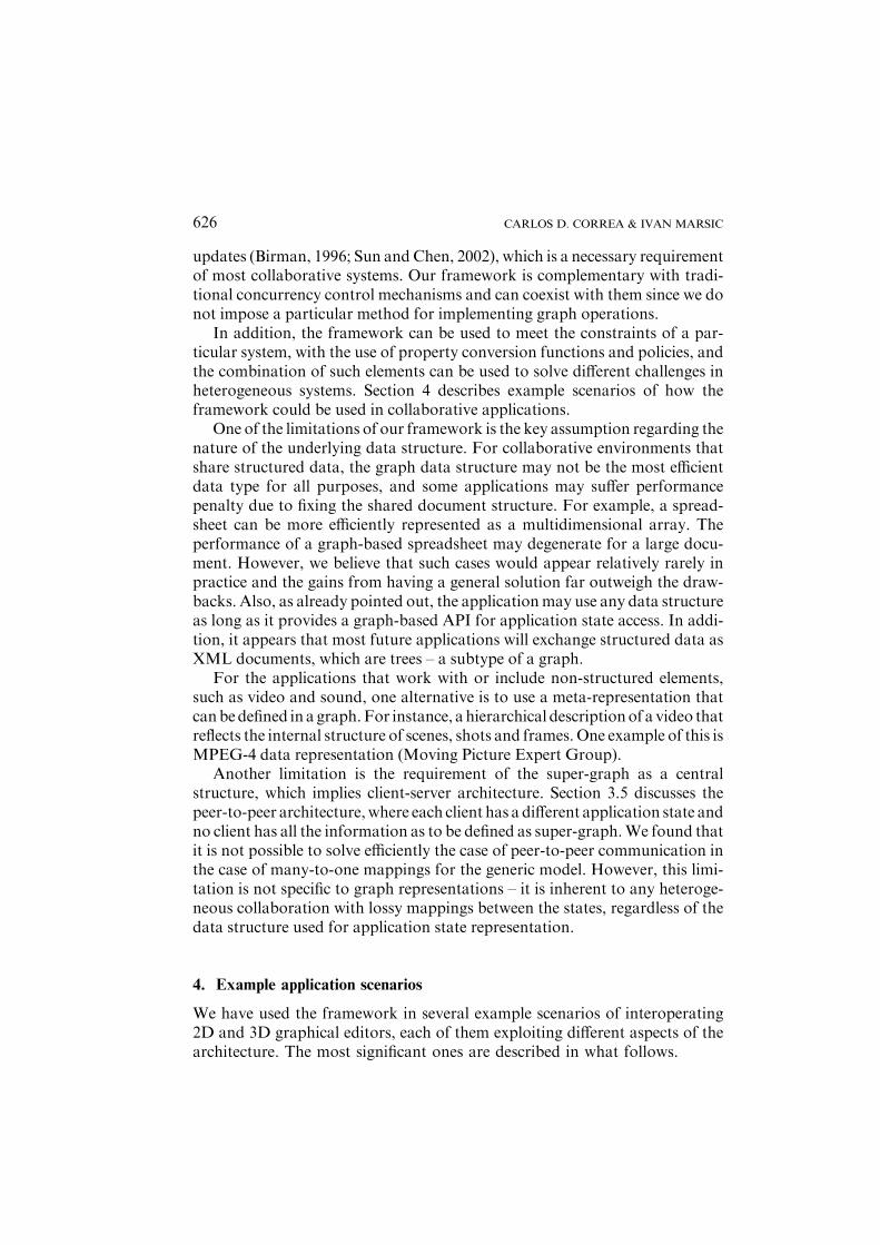
Figure 8. Software architecture of a collaborative scenario described in the text.
CARLOS D. CORREA & IVAN MARSIC628

specified by the application developer (or by the user through a set ofpreferences), to solve the ambiguities.
In Figure 6, a high-end client’s graph (Client 1) exactly corresponds to theserver super-graph. Note that it is possible to display an isometric view of themodel in the 2D application. This is accomplished with a slight modificationof the property conversion functions w, namely those that convert 3D to 2Dcoordinates. This conversion is usually performed by multiplying the ele-ments in 3D by a projection matrix. Depending on the point of view, theprojection matrix will change.
4.3. CONSTRAINTBASED SIMPLIFICATION OF HIERARCHICAL DATA
Yet another aspect of heterogeneity is the differences in state representationsthat arise from lossy simplification that ‘‘compresses’’ the state to fit into thescarce system resources of the client device. Availability of resources such asbandwidth, memory, and computing power, limits the amount of informa-tion that can be sent and displayed in a given device. We used our frameworkfor enabling collaboration over 3D models on mobile devices, where an officeworker on a workstation and a field worker on a PDA collaborate on a 3Dmodel. The 3D model in the workstation is detailed and complex, while thePDA works with an approximation. As the mobile user interacts with themodel and navigates to different parts of it, the model is dynamically mor-phed so as to detail those parts that become the focus of attention of the user.Our framework solves this as follows:
0
100
200
300
400
500
600
700
800
900
500 1000 2000 5000 10000
Limit in Resources (# polygons)N
etw
ork
tra
ffic
(K
B)
cityhouses bike
0
500
1000
1500
2000
2500
3000
3500
4000
3 4 5 6 8
Level of detail
Net
wo
rk t
raff
ic (
KB
)
cityhouses bike
(b) (c)
city houses bike (a)
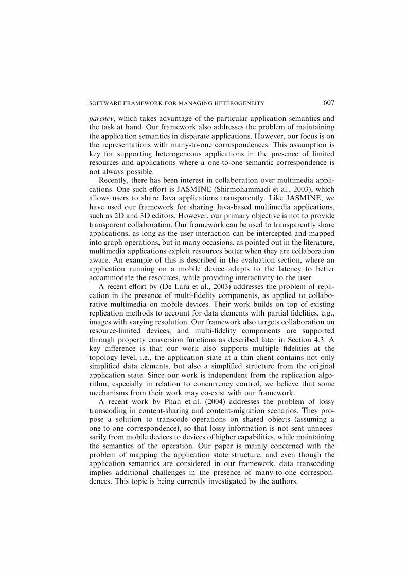
Figure 9. Network traffic for different documents: (a) Virtual scenes used in the experiment; (b)
Using rule-based mapping; (c) Using optimization. (Note the difference in scale between the two.)
SOFTWARE FRAMEWORK FOR MANAGING HETEROGENEITY 629

• To lower the demand for resources needed for transmitting and renderingthe 3D model in a PDA, the scene graph (tree data structure) is simplifiedby contracting the vertices of an entire subtree into single elements orimpostors.
• To meet the resource constraints, the problem is represented and solvedas combinatorial optimization. For this, each vertex in the scene graph isassigned benefit and cost values, which represent its contribution touser’s utility and required system resource, respectively. An example ofuser’s utility is perceptual fidelity of the scene. The resulting client graphmaximizes the benefit metric while keeping the resources below a giventhreshold (see example in Figure 7).
• To interoperate property values of impostors and their correspondingsubtrees, property conversion functions and their respective aggregationoperation are provided. This is essential for keeping the simplified rep-licas consistent with the original 3D model.
In a related work (Correa et al., 2002), we developed an algorithm that solvesexactly this optimization problem, which is a variation of the Tree KnapsackProblem (Cho and Shaw, 1997). We used the results to improve interactivityin collaborative virtual worlds on mobile devices, by guaranteeing a mini-mum update rate at the cost of (optimally) lowering fidelity.
An application where the above scenarios constitute an important part,and where our framework offers a significant contribution, is CollaborativeAugmented Reality. Augmented Reality (AR) applications superimposecomputer-generated images onto the view of the real world, through devicessuch as head-mounted displays, PDAs or tablet PCs. In collaborative AR,one or more users have this enhanced view of the virtual world, while otherusers share the same view through a virtual replica of the real place(Reitmayr and Schmalstieg, 2001). In such applications, real-time constraintsare very tight, particularly regarding the rendering cost of the 3D scene andinteraction latency. In addition, filtering out of information is critical, since
(a) (b)
0
20
40
60
80
100
120
140
160
3 4 5 6 8
Level of Detail
Ser
ver
Tim
e (m
illis
eco
nd
s)
cityhouses bike
020406080
100120140160180200220240
500 1000 2000 5000 10000
Limit in Resources (# polygons)
Ser
ver
Tim
e (m
illis
eco
nd
s)
cityhouses bike
Figure 10. Server time for different documents: (a) Using rule-based mapping; (b) Using optimi-
zation. (Note the difference in scale between the two.)
CARLOS D. CORREA & IVAN MARSIC630

some elements present in the virtual world do not need to be retrieved in theaugmented view (given that the user ‘‘sees’’ the real thing), while some otherelements can simply be represented using tags, as in, e.g., the touring machineof Feiner et al. (1997).
5. Evaluation
We tested different collaborative scenarios for the different aspects of het-erogeneity we intend to solve. The software architecture is depicted in Fig-ure 8. In a typical scenario, 3D and 2D users collaboratively visualize a set ofvirtual objects, e.g., Figure 6. When the user interacts with the environment,a set of operations is performed on the application’s graph. When theseoperations are sent to the server, they are transformed to operations in thesuper-graph, according to the client’s graph mapping and the algorithmsdescribed in Section 3. The operations in the server-graph are accordinglytransformed into operations on the other client graphs. Note that in somecases, the mapping will be specified by a set of rules, whereas in other cases itwill be result from an optimization process (Section 3.4.1). In our particularapplication, it is the user who selects which mapping method is used. Theoptimization process simplifies a hierarchical document in the best waypossible, according to some pre-defined benefit metric, such that the con-straints in resources are met (Correa et al., 2002).
An important quality metric for this framework is performance. In (mo-bile) collaborative systems, the performance metrics critical for providinginteractivity are efficient use of resources and the interactive response latency.Unfortunately, these are inversely coupled and represent a tradeoff. If theapplication needs to meet a certain constraint in resources, particularly inwireless devices, it is necessary to run complex computations that increase the
0
2000
4000
6000
8000
10000
12000
1 11 21 31 41 51 61 71
frame
late
ncy
(m
s)
RTT AVGRTT
0%
20%
40%
60%
80%
100%
1 6 11 16 21 26 31 36 41 46 51 56 61 66 71 76
frame
per
cen
tag
e o
f to
tal l
aten
cy
Network
Client
Server
(a) (b)
Figure 11. Network latency for virtual world navigation with no adaptation: (a) Total latency in
milliseconds; (b) Network, client and server components of latency in percentage.
SOFTWARE FRAMEWORK FOR MANAGING HETEROGENEITY 631
latency. Contrariwise, if the application needs to minimize the latency, it mayhave to exceed the threshold of allowed resource usage.
5.1. RESOURCE UTILIZATION
In (Correa and Marsic, 2003), we illustrated the resource-latency tradeoff byusing our framework to transcode a set of 3D objects in a collaborativeeditor. We showed how resource efficiency can be achieved with optimiza-tion-based mapping, while rule-based mapping does not provide any effi-ciency guarantees. Given that the objects in that experiment were relativelysmall, differences in response time were not noticeable. For this reason, herewe conducted a different experiment over larger 3D models.
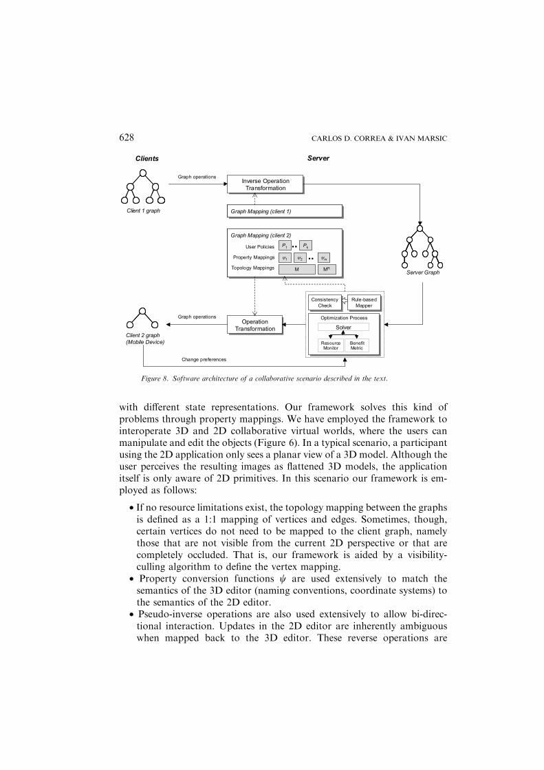
We used three large datasets, called city, houses, and bike, as depicted inFigure 9(a), which were built using freely available 3D objects. The scenegraphs for these models are specified in XML format, with file sizes of 6014KB, 2365 KB, and 8791 KB, respectively. The sizes of their respective trees(in terms of the number of vertices) are 127, 255 and 120, and the tree heightsare 7, 8, and 7, respectively
For measuring the response time and resource efficiency of our frame-work, we measured the time it takes for a complete 3D object (represented asa scene graph) to be mapped to the client, and the amount of network trafficgenerated. We compare two methods for mapping definition, rule-basedmapping vs. optimization, as defined in Section 3.4.1, whose main parameterswhere varied: (1) The level-of-detail parameter for rule-based mapping,which specifies the height of the resulting tree in the client graph (such as theset of rules described in Figure 3); and, (2) the limit of resources, in terms ofnumber of polygons, for the case of optimization. We ran our experiments ona 2.2 GHz Intel XEON computer with 1GB RAM.
The resource-latency tradeoff is evident in Figures 9 and 10. In terms ofresource utilization, optimization-based mapping provides a better efficiency,as expected, since it guarantees that the required resources do not exceed thelimit. In this case, there is a linear relation between the number of polygonsand network usage, which ensures that the network requirements (availablebandwidth) will not be exceeded for any dataset, Figure 9(c). Conversely,rule-based mapping does not offer resource guarantees and the networkrequirements increase rapidly as the level of detail is increased, Figure 9(b).In terms of response time, Figure 10 shows that the server time is not sen-sitive to changes in the level-of-detail parameter for the rule-based case,whereas it increases linearly with the limit on resources for the case ofoptimization, due to the particular algorithm we developed for solving theproblem, as explained below.
CARLOS D. CORREA & IVAN MARSIC632
5.2. LATENCY
In order to measure latency, we performed both analytical and empiricalstudies. Latency, as perceived by the user, is the sum of several delays in theprocess of mapping operations from the server to the client.
Latency ¼ tSERVER þ network delayþ tCLIENT;
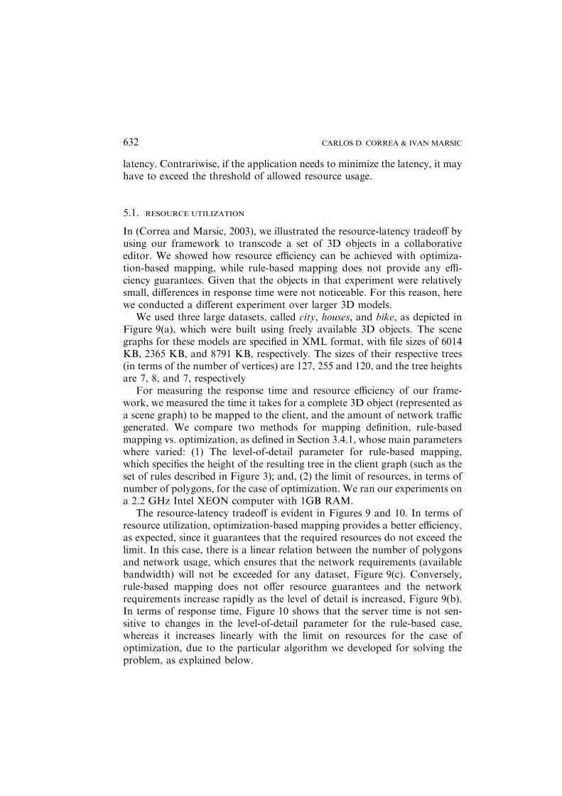
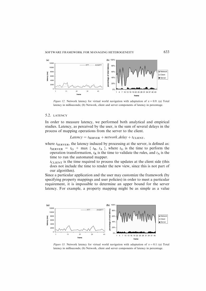
where tSERVER, the latency induced by processing at the server, is defined as:tSERVER = tG + max { tR, tA }, where tG is the time to perform theoperation transformation, tR is the time to validate the rules, and tA is thetime to run the automated mapper.tCLIENT is the time required to process the updates at the client side (thisdoes not include the time to render the new view, since this is not part ofour algorithm).
Since a particular application and the user may customize the framework (byspecifying property mappings and user policies) in order to meet a particularrequirement, it is impossible to determine an upper bound for the serverlatency. For example, a property mapping might be as simple as a value
(a) (b)
0
2000
4000
6000
8000
10000
12000
1 11 21 31 41
frame
late
ncy
(m
s)
RTT AVGRTT
0%
20%
40%
60%
80%
100%
1 4 7 10 13 16 19 22 25 28 31 34 37 40 43
frame
per
cen
tag
e o
f to
tal l
aten
cy
Network
Client
Server
Figure 12. Network latency for virtual world navigation with adaptation of a ¼ 0.9: (a) Total
latency in milliseconds; (b) Network, client and server components of latency in percentage.
(a) (b)
0
2000
4000
6000
8000
10000
12000
1 11 21 31 41
frame
late
ncy
(m
s)
RTT AVGRTT
0%
20%
40%
60%
80%
100%
1 4 7 10 13 16 19 22 25 28 31 34 37 40
frame
per
cen
tag
e o
f to
tal l
aten
cy
Network
Client
Server
Figure 13. Network latency for virtual world navigation with adaptation of a ¼ 0.1: (a) Total
latency in milliseconds; (b) Network, client and server components of latency in percentage.
SOFTWARE FRAMEWORK FOR MANAGING HETEROGENEITY 633

conversion, which takes O(1) time, or it might involve a large dependencytree, which could increase latency by an order of magnitude.
We are able to bound the delay of topological operations. From Section3.4.2 we see that for most cases, operation transformation involve a singleoperation on the graph. However, for many-to-one correspondences it takesO(k) time in the worst case, where k is the number of vertices in the servergraph which are mapped to a single vertex in the client graph or the numberof edges in a path which are mapped to a single edge in the client graph. For aset of n operations, such as creating a tree of size n, the graph mapping takesO(n) time, on the average. This can be seen from Figure 10(a), where servertimes scale linearly with the tree size. The delay due to optimization dependslargely on the algorithm used to solve the optimization problem. In ourexperimental scenario, we use an exact algorithm that takes O(nR) time,where n is the size of the tree and R is the limit in resources. Figure 10(b)shows evidence of this time complexity.
We use our application in a collaborative scenario where two users share avirtual world. One of the users interacts from a PDA, while the other uses apowerfulworkstation.Themobile device is aCompaq iPAQPocket PCH3870.In this scenario, the mobile client is not capable of displaying the entire virtualworld. Instead, a simplified version is retrieved from the server, such that theelements closer to the user’s focus of attention are represented in more detailthan the rest. The PDA is connected to a proxy server via an 11-Mbps 802.11bwireless link, which in turn is connected to the wired local area network wherethe other user is. The proxy server runs an implementation of our framework,using a constraint-based mapping-generation module to support the adapta-tion to resources in themobile device (see Section 4.3).Wemeasured the latencyof updates at the client side, as the mobile user navigates around the worldshown inFigure 6. Figure 11 plots the latency for this scenario, divided in threecomponents: time of processing at the server, network delay, and processing atthe client. Two important observations from these results are:
• Latency increases rapidly to non-acceptable rates (more than 10 s). Thisis due to the fact that the rate at which the user navigates around theworld (labeled as AVGRTT in the figure) is 10 Hz (updates per second),which at some points is much higher than the rate at which the client isable to process them. This results in flooding of the client process and anincreased latency. In many applications, the update frequency can beeven higher (around 40 Hz or one update each 25 ms) so the resultinglatency is even worse.
• For our mobile scenario, server processing is insignificant in comparisonwith the high latency of wireless links and the processing at the clientside, assuming that the server attends small number of clients. However,server processing in many cases is very sensitive to an increase in the size
CARLOS D. CORREA & IVAN MARSIC634

of the server graph. This occurs when the graph mapping is generatedthrough an optimization process, which is known to be NP-Complete(Johnson and Niemi, 1983). This means that for a large number of ele-ments (a large virtual world or document), the time to compute themapping tA grows exponentially, while network delay and client pro-cessing time grows linearly. In our previous work, we have experimentedwith several approaches to solve this optimization problem (Correaet al., 2002; Correa and Marsic, 2004). Greedy algorithms are known toapproximate the problem efficiently, but there is no guarantee regardingthe optimality of the solution (Johnson and Niemi, 1983). For this rea-son, in (Correa et al., 2002) we have developed an algorithm that opti-mally simplifies a hierarchical structure in O(n ÆR) time, where n is thesize of the tree, and R is the upper bound in resources (available band-width, memory, etc.). See for instance the results in Figure 10(b).
5.2.1. Adaptation to LatencyAs visible in Figure 11, network delay is substantial in wireless connections.For this reason and the fact that delay may vary arbitrarily for differentoperations, it is necessary to adapt to latency. We perform the adaptation bysetting a maximum update rate, computed as follows.
Each time a packet arrives, we sample the round-trip time (SampleRTT)and compute the average round-trip time (AverageRTT) using a runningaverage (similar as in the TCP protocol):
AverageRTT ¼ a� AverageRTTþ ð1� aÞ � SampleRTT;
UpdateRate ¼ 1
AverageRTT:
The server will only transmit information to the client at a rate lower than orequal to UpdateRate. Since some operations may be considered transient (i.e.,their effects are not final and are overridden by a subsequent operation, e.g.,intermediary steps in object manipulation), those updates arriving faster thanUpdateRate can be discarded in order to reduce the effects of high latency. Inthe case of optimal simplification (Section 4.3), this adaptation is performed onthe mobile client instead of the server, when retrieving scene updates. Thiscompromises the transparency of the adaptation, but it is more resource effi-cient, since it allows the client to control the frequency of requests over thewireless link. Figure 12 shows the resulting latency for the same scenario as inFigure 11 with a latency adaptation of a ¼ 0.9. Note that there is a significantdifference in the total latency. We also experimented with several values of a,and we found no significant difference in their mean latency. This is expectedsince, in the long run, any value 0 < a < 1 has a tendency to maintain thelatency around the same average, although there is an agility vs. stability
SOFTWARE FRAMEWORK FOR MANAGING HETEROGENEITY 635
tradeoff. Small values of a result in high round-trip time variabilitywhile valuescloser to 1 yield more stable behavior. Conversely, values closer to 0 result ingreater agility in reacting to sudden changes in the latency, while values closerto 1 result in a slower adaptation. Compare for example the results in Figure 12(a ¼ 0.9) with those in Figure 13 (a ¼ 0.1).
Our experiments suggest that the result of adaptation is independent of theinitial condition in latency, i.e., the total average latency tends to converge tothe same value regardless of the initial value of latency.We computed this resultby measuring the latency for a constant value a, while varying the initial con-ditions for latency. We repeated this for different values of a. This is of par-ticular interest in mobile collaborative systems, since the latency in wirelessnetworks exhibits a large variability and is sensitive to a variety of factors.
6. Conclusions
We have developed a framework that manages heterogeneity in collaborativesystems using customizable graph mappings. Graph mappings are obtainedthrough a combination of topological mappings, used to structurally simplifythe shared data-structure, property mappings, and user-defined policies. Thekey function of the framework is providing consistent application states todifferent participants, under different aspects of heterogeneity: disparate devicecapabilities, user’s interest and applicationdomaindifferences.We showed thatin addition to providing consistency, our framework can be used to guaranteeresource bounds, such as limited bandwidth, memory usage and computingpower, which are critical in mobile devices. Another important issue withcollaborative systems is latency, which usually represents a tradeoff with theoptimal management of system resources. We introduced an adaptationtechnique to reduce the latency inmobile scenarios: bounding the update rate oftransmission using a running average of the delays reduces the network delay,which is particularly noticeable inwireless networks.An important implicationof this is that in order to support collaborative work inmobile scenarios, whereheterogeneity is present, it is necessary tonegotiate the available resources, suchas bandwidth and latency, which often results in a tradeoff. The frameworkpresented in this paper allows the negotiation of resources via lossy graphmappings, and allows the adaptation to latency in order to minimize the effectsof such tradeoff.
Acknowledgements
The authors are indebted to the anonymous reviewers, whose commentshelped to greatly improve the quality of the paper. This research is supportedin part by NSF Grant ANI-01-23910 and by the Rutgers Center for Ad-vanced Information Processing (CAIP).
CARLOS D. CORREA & IVAN MARSIC636
References
Birman, K. P. (1996): Building Secure and Reliable Network Applications. Manning PublishingCompany.
Bright, M.W., A.R. Hurson and S. Pakzad (1994): Automated Resolution of Semantic Het-
erogeneity in Multidatabases. ACM Trans. on Database Systems, vol. 19, no. 2, pp. 212–253.
Britton, K.H., R. Case, A. Citron, R. Floyd, Y. Li, C. Seekamp, B. Topol and K. Tracey
(2001): Transcoding: Extending e-Business to New Environments. IBM Systems Journal,vol. 40, no. 1, pp. 153–178.
Ceri S. and J. Widom (1993): Managing Semantic Heterogeneity with Production Rules and
Persistent Queues. Proceedings of the 9th International Conference on Very Large DataBases, Dublin, Ireland, pp. 108–119.
Cho, G. and D.X. Shaw (1997): A Depth-First Dynamic Programming Algorithm for the TreeKnapsack Problem. INFORMS Journal of Computing, vol. 9, no. 4, pp. 431–438.
Connolly, T., C. Begg and A. Strachan (1996): Database Systems: A Practical Approach toDesign, Implementation, and Management. Wokingham, UK: Addison-Wesley.
Correa, C.D. and I. Marsic (2003): Software Framework for Managing Heterogeneity in
Mobile Collaborative Systems. Proceedings of the ACM International Conferences onSupporting Group Work (GROUP ’03), Sanibel Island, FL, pp. 125–134.
Correa, C.D. and I. Marsic (2004): Simplification Architecture for Exploring Navigation
Tradeoffs in Mobile VR. Proceedings of the IEEE Virtual Reality Conference (VR2004),Chicago, IL, pp. 133–140.
Correa, C., I. Marsic and X. Sun (2002): Semantic Consistency Optimization in Heterogeneous
Virtual Environments. Rutgers University, CAIP Center, Technical Report CAIP-TR-267.Online at: http://www.caip.rutgers.edu/disciple/.
De Lara, E., R. Kumar, D.S. Wallach and W. Zwaenepoel (2003): Collaboration and Mul-timedia Authoring on Mobile Devices. Proceedings of the 1st International Conference on
Mobile Systems, Applications, and Services (MobiSys 2003), San Francisco, CA, pp. 287–301.
Feiner, S., B. MacIntyer, T. Hollerer and T. Webster (1997): A Touring Machine: Prototyping
3DMobile Augmented Reality Systems for Exploring the Urban Environment. Proceedingsof the IEEE International Symposium Wearable Computers (ISWC ’97), Cambridge, MA,pp. 208–217.
Fox, A., S.D. Gribble, Y. Chawathe and E.A. Brewer (1998): Adapting to Network and ClientVariation Using Active Proxies: Lessons and Perspectives. IEEE Personal Communications(Special Issue on Adapting to Network and Client Variability), vol. 5, no. 4, pp. 10–19.
Funkhouser, T.A. and C.H. Sequin, (1993): Adaptive Display Algorithm for InteractiveFrame Rates During Visualization of Complex Virtual Environments. Computer Graphics(SIGGRAPH ’93), vol. 27, pp. 247–254.
Hall, R.W., A. Mathur, F. Jahanian, A. Prakash and C. Rassmussen (1996): Corona: A
Communication Service for Scalable, Reliable Group Collaboration Systems. Proceedingsof the ACM Conference on Computer Supported Cooperative Work (CSCW ’96), Boston,MA.
Johnson, D.S. and K.A. Niemi (1983): On Knapsacks, Partitions, and a New DynamicProgramming Technique for Trees. Mathematics of Operations Research, vol. 8, no. 1, pp.1–14.
Knister, M.J. and A. Prakash (1990): DistEdit: A Distributed Toolkit for Supporting MultipleGroup Editors. Proceedings of the ACM Conferences on Computer Supported CooperativeWork (CSCW ’90), Los Angeles, CA, pp. 343–355.
SOFTWARE FRAMEWORK FOR MANAGING HETEROGENEITY 637

Li, D. and L. Rui, (2002): Transparent Sharing and Interoperation of Heterogeneous Single-User Applications. Proceedings of the ACM Conference on Computer Supported CooperativeWork (CSCW ’02), New Orleans, LA, November, pp. 246–255.
Lum, W.Y. and F.C.M. Lau (2002): On Balancing Between Transcoding Overhead and
Spatial Consumption in Content Adaptation. Proceedings of the 8th International Confer-ence on Mobile Computing and Networking (MobiCom ’02), Atlanta GA, pp. 239–250.
Mani, I. (2001): Automatic Summarization. Amsterdam/Philadelphia: John Benjamins Pub-
lishing Company.Marcu, D. (2000): The Theory and Practice of Discourse Parsing and Summarization. Cam-
bridge, MA: The MIT Press.
Marsic, I., X. Sun, C. Correa and T. Liu, (2002): Maintaining State Consistency AcrossHeterogeneous Collaborative Applications, Rutgers University, CAIP Center, TechnicalReport CAIP-TR-264. Online at: http://www.caip.rutgers.edu/disciple.
Mascolo, C., L. Capra, S. Zachariadis and W. Emmerich (2002): XMIDDLE: A Data-Sharing
Middleware for Mobile Computing. Wireless Personal Communications: An InternationalJournal, vol. 21, no. 1, pp. 77–103.
Mason, A.E.W. and E.H. Blake (2001): A Graphical Representation of the State Spaces of
Hierarchical Level-of-Detail Scene Descriptions. IEEE Transactions on Visualization andComputer Graphics, vol. 7, no. 1, pp. 70–75.
Munson, J. and P. Dewan (1996): A Concurrency Control Framework for Collaborative
Systems. Proceedings of the ACM Conference on Computer Supported Cooperative Work(CSCW ’96), Boston, MA, pp. 278–287.
Moving Picture Experts Group web page (2003) Online at: http://www.mpeg.org
Phan, T., G. Zorpas and R. Bagrodia (2004): Middleware Support for Reconciling ClientUpdates and Data Transcoding. Proceedings of the 2nd International Conference on MobileSystems, Applications, and Services (MobiSys 2004), Boston, MA, pp. 139–152.
Reitmayr, G. and D. Schmalstieg (2001): Mobile Collaborative Augmented Reality. Pro-
ceedings of the International Symposium on Augmented Reality (ISAR ’01), pp. 114–123.Sciore, E., M. Siegel and A. Rosenthal (1994): Using Semantic Values to Facilitate Interop-
erability Among Heterogeneous Information Systems. ACM Transactions on Database
Systems, vol. 19, no. 2, pp. 254–290.Shirmohammadi, S., A. El Saddik, N.D. Georganas and R. Steinmetz (2003): JASMINE: A
Java Tool for Multimedia Collaboration on the Internet, J. Multimedia Tools and Appli-
cations, vol. 19, no. 1, pp. 5–28.Sun, C. and C.A. Ellis (1998): Operational Transformation in Real-Time Group Editors:
Issues, Algorithms and Achievements. Proceeding of the ACM Conference on ComputerSupported Cooperative Work (CSCW ’98), Seattle, WA, pp. 59–68.
Sun, C. and D. Chen (2002): Consistency Maintenance in Real-Time Collaborative GraphicsEditing Systems. ACM Transactions on Computer-Human Interaction, vol. 9, no. 1, pp. 1–41.
SyncML Initiative Ltd. (2002): SyncML – Mobile Data Synchronization Protocol. Online at:http://www.syncml.org
CARLOS D. CORREA & IVAN MARSIC638