Embed Size (px)
Citation preview
1
Threads, Tools, Gauges and Calibration Management
web: www.qsyst.com email: [email protected]
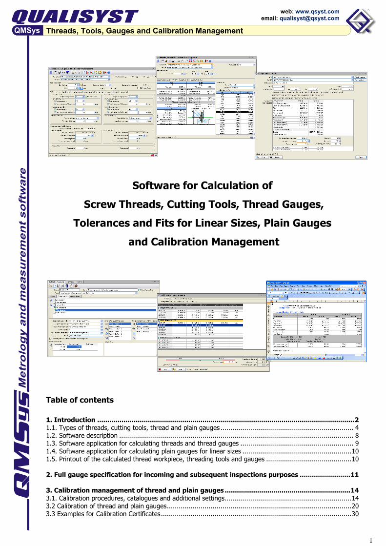
Software for Calculation of Screw Threads, Cutting Tools, Thread Gauges,
Tolerances and Fits for Linear Sizes, Plain Gauges and Calibration Management
Table of contents 1. Introduction ............................................................................................................................... 2 1.1. Types of threads, cutting tools, thread and plain gauges ................................................................... 4 1.2. Software description ...................................................................................................................... 8 1.3. Software application for calculating threads and thread gauges ......................................................... 9 1.4. Software application for calculating plain gauges for linear sizes ....................................................... 10 1.5. Printout of the calculated thread workpiece, threading tools and gauges ........................................... 10 2. Full gauge specification for incoming and subsequent inspections purposes ......................... 11 3. Calibration management of thread and plain gauges .............................................................. 14 3.1. Calibration procedures, catalogues and additional settings................................................................ 14 3.2 Calibration of thread and plain gauges ............................................................................................. 20 3.3 Examples for Calibration Certificates ................................................................................................ 30
2
Threads, Tools, Gauges and Calibration Management
web: www.qsyst.com email: [email protected]
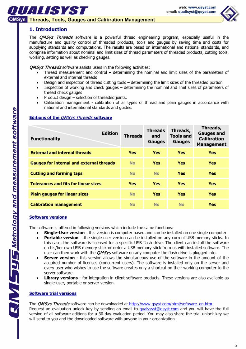
1. Introduction The QMSys Threads software is a powerful thread engineering program, especially useful in the manufacture and quality control of threaded products, tools and gauges by saving time and costs for supplying standards and computations. The results are based on international and national standards, and comprise information about nominal and limit sizes of thread parameters of threaded products, cutting tools, working, setting as well as checking gauges. QMSys Threads software assists users in the following activities:
• Thread measurement and control – determining the nominal and limit sizes of the parameters of external and internal threads
• Design and inspection of thread cutting tools – determining the limit sizes of the threaded portion • Inspection of working and check gauges – determining the nominal and limit sizes of parameters of
thread check gauges • Product design – selection of threaded joints. • Calibration management - calibration of all types of thread and plain gauges in accordance with
national and international standards and guides. Editions of the QMSys Threads software
Edition
Functionality
Threads Threads
and Gauges
Threads, Tools and
Gauges
Threads, Gauges and Calibration
Management External and internal threads Yes Yes Yes Yes
Gauges for internal and external threads No Yes Yes Yes
Cutting and forming taps No No Yes Yes
Tolerances and fits for linear sizes Yes Yes Yes Yes
Plain gauges for linear sizes No Yes Yes Yes
Calibration management No No No Yes
Software versions
The software is offered in following versions which include the same functions:
• Single-User version - this version is computer based and can be installed on one single computer. • Portable version – the single-user version can be installed on any current USB memory sticks. In
this case, the software is licensed for a specific USB flash drive. The client can install the software on his/her own USB memory stick or order a USB memory stick from us with installed software. The user can then work with the QMSys software on any computer the flash drive is plugged into.
• Server version - this version allows the simultaneous use of the software in the amount of the acquired number of licenses (concurrent users). The software is installed only on the server and every user who wishes to use the software creates only a shortcut on their working computer to the server software.
• Library versions - for integration in client software products. These versions are also available as single-user, portable or server version.
Software trial versions The QMSys Threads software can be downloaded at http://www.qsyst.com/html/software_en.htm. Request an evaluation unlock key by sending an email to [email protected] and you will have the full version of all software editions for a 30-day evaluation period. You may also share the trial unlock key we will send to you and the downloaded software with anyone in your organization.

3
Threads, Tools, Gauges and Calibration Management
web: www.qsyst.com email: [email protected]
Calculating thread, tolerances, fits, thread and plain and gauges The most important features offer:
• Compliance with the latest revisions of ISO, EN, DIN, ANSI, ASME, BS, JIS, IS, SAE, API and other corresponding national standards.
• Calculation of threads with nominal sizes from 0.25 mm up to 1250 mm (0.1 - 50 in.) • Calculation of tolerances and fits for linear sizes up to 10000 mm (ISO) or up to 200 in. (ANSI) • Plain gauges according to ISO standards up to 500 mm, according to ASME standards up to 19.69
in. and according to BS standards for workpiece tolerances 0.005 - 3.2 mm (0.0002 - 0.125 in.) • The thread parameters can be chosen from the respective list or can be inserted directly; this
facilitates and smoothens the work process, since it is not necessary to remember the designation of each thread type
• Recommended in the respective standards nominal sizes, pitches and tolerance classes • After entering the thread parameters, all types of working, setting and checking gauges are being
calculated; the user does not have to bother with repeated entry of the same data for different gauges.
• Nominal and limit sizes on all thread and gauge characteristics - diameters, pitch, lead, flank angles, length of gauge and tolerance steps, crest and root flats, etc.
• Figures from the corresponding standard for thread profile, tolerance zone, gauge profile. • Calculation of diameter corrections for all types of finishing: removing (reshaping) or adding
(altering). • Computation of limits for measuring of the pitch diameter with wires or balls, with consideration of
the influence of a measuring force, material of the threaded workpiece and the resulting deformations.
• Printing out in standard or custom adjustable templates in RTF, XLS or TXT format • Coping of the results in the clipboard • User-friendly interface, evidently easier design for usage and result interpretation. • Possibility for development of customer thread types (after providing the respective standards).
Calibration management for thread and plain gauges Calibration process of the thread and plain gauges is developed in accordance with international and national standards and guidelines:
• ISO, ANSI/ASME, DIN and BS standards for the respective thread types • DAkkS-DKD-R 4-3 Testing instructions, Parts 4.1, 4.2, 4.3, 4.6, 4.7, 4.8, 4.9 • VDI/VDE/DGQ 2618 Testing instructions, Parts 4.1, 4.2, 4.3, 4.6, 4.7, 4.8, 4.9 • MIL-STD-I20 Gauge Inspection • IFI 301 Gage Calibration Requirements and Procedures for Thread Gages • EURAMET cg-6 - Extent of calibration for cylindrical diameter standards • EURAMET cg-10 - Determination of pitch diameter of parallel thread gauges by mechanical probing • ILAC-G8:03 - Guidelines on the reporting of compliance with specification • ISO 14253-1 - Decision rules for proving conformance or non-conformance with specifications • ASME B89.7.3.1 - Guidelines for decision rules: Considering measurement uncertainty determining
conformance to specifications. Before calibrating the gauges, the user should create calibration procedures for the respective types of gauges and fill in the catalogues for measuring instruments, wire and ball probe sets. The calibration procedures include all relevant metrological characteristics - gauge length, lengths of tolerance steps, thread and flank angles, pitch and lead, major diameter, pitch diameter, minor diameter, taper, form deviations. The software also offers several methods for measurement of the pitch diameter over wires and balls - three or two wires, ball probes, perpendicular or inclined. During the measurement, the software calculates the limits of indicated values for the selected method, diameter of the wires or balls and measuring force. Measurements can be entered manually by the keyboard or transferred automatically from any measuring instrument or machine, equipped with serial RS 232 or USB interface. Inspection and adjustment of working gauges with the respective checking, setting or master gauges is also implemented in the design of calibration procedures and the calibration process.
4
Threads, Tools, Gauges and Calibration Management
web: www.qsyst.com email: [email protected]
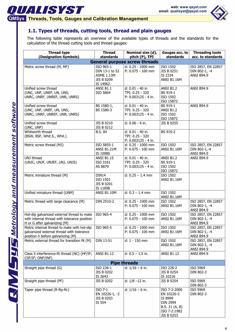
1.1. Types of threads, cutting tools, thread and plain gauges The following table represents an overview of the available types of threads and the standards for the calculation of the thread cutting tools and thread gauges:
Thread type (Designation Symbols)
Thread standards
Nominal size (d), pitch (P), TPI
Gauges acc. to standards
Threading tools acc. to standards
General purpose screw threads Metric screw thread (M, MF)
ISO 965-1 DIN 13-1 to 52 ASME 1.13M JIS B 0209 IS 14962
d: 0.25 - 1000 mm P: 0.075 - 100 mm
ISO 1502 JIS B 0251 IS 2334 ANSI B1.16M
ISO 2857, EN 22857 DIN 802-1, -4 ANSI B94.9
Unified screw thread (UNC, UNF, UNEF, UN, UNS, UNRC, UNRF, UNREF, UNR, UNRS)
ANSI B1.1 ISO 5864
d: 0.01 - 40 in TPI: 0.25 - 320 P: 0.003125 - 4 in.
ANSI B1.2 BS 919-1 ISO 1502 ISO 15872
ANSI B94.9
Unified screw thread (UNC, UNF, UNEF, UN, UNS, UNRC, UNRF, UNREF, UNR, UNRS)
BS 1580-1, BS 1580-3
d: 0.01 - 40 in. TPI: 0.25 - 320 P: 0.003125 - 4 in.
BS 919-1 ANSI B1.2 ISO 1502 ISO 15872
ANSI B94.9
Unified screw thread (UNC, UNF)
JIS B 0210 JIS B 0212
d: 0.06 - 4 in.
JIS B 0255
Whitworth thread (BSW, BSF, Whit.S., Whit.)
B.S. 84 d: 0.01 - 40 in. TPI: 0.25 - 320 P: 0.003125 - 4 in.
BS 919-2
Metric screw thread (MJ)
ISO 5855-1 ANSI B1.21M IS 10980
d: 0.25 - 1000 mm P: 0.075 - 100 mm
ISO 1502 ANSI B1.16M
ISO 2857, EN 22857 DIN 802-1,-4 ANSI B94.9
UNJ thread (UNJC, UNJF, UNJEF, UNJ, UNJS)
ANSI B1.15 ISO 3161 AS 8879
d: 0.01 - 40 in. TPI: 0.25 - 320 P: 0.003125 - 4 in.
ANSI B1.2 BS 919-1 ISO 1502 ISO 15872
ANSI B94.9
Metric miniature thread (M)
DIN14 ISO 1501 JIS B 0201 IS 11698
d: 0.25 – 1.4 mm ISO 1502 ANSI B1.16M
Unified miniature thread (UNM) ANSI B1.10M d: 0.3 – 1.4 mm ISO 1502 ANSI B1.16M
Metric thread with large clearance (M) DIN 2510-2 d: 0.25 - 1000 mm P: 0.075 - 100 mm
ISO 1502 ANSI B1.16M
ISO 2857, EN 22857 DIN 802-1, -4 ANSI B94.9
Hot-dip galvanized external thread to mate with internal thread with tolerance position H or G after galvanizing (M)
ISO 965-4 d: 0.25 - 1000 mm P: 0.075 - 100 mm
ISO 1502 ANSI B1.16M
ISO 2857, EN 22857 DIN 802-1, -4 ANSI B94.9
Metric internal thread to mate with hot-dip galvanized external thread with tolerance position h before galvanizing (M)
ISO 965-5 d: 0.25 - 1000 mm P: 0.075 - 100 mm
ISO 1502 ANSI B1.16M
ISO 2857, EN 22857 DIN 802-1, -4 ANSI B94.9
Metric external thread for transition fit (M) DIN 13-51 d: 1 - 150 mm
ISO 1502 ANSI B1.16M
ISO 2857, EN 22857 DIN 802-1, -4 ANSI B94.9
Class 5 interference-fit thread (NC) (HF/IF; CSF/IF; ONF/INF)
ANSI B1.12 d: 0.5 – 1.5 in.
ANSI B1.12 ANSI B94.9
Pipe threads Straight pipe thread (G) ISO 228-1
JIS B 0202 IS 2643
d: 1/16 – 6 in. ISO 228-2 JIS B 0254 IS 10216
ISO 5969 DIN 802-3
Straight pipe thread (PF) JIS B 0202
d: 1/8 –12 in. JIS B 0254 ISO 5969 DIN 802-3
Taper pipe thread (R-Rp-Rc)
ISO 7-1 EN 10226-1, -2 JIS B 0203 IS 554
d: 1/16 – 6 in. ISO 7-2:2000 EN 10226-3 IS 8999 DIN 2999 B.S. 21 (A, B) ISO 7-2:1982 JIS B 0253
ISO 5969 DIN 802-3

5
Threads, Tools, Gauges and Calibration Management
web: www.qsyst.com email: [email protected]
Types of threads (cont'd)
Thread type (Designation Symbols)
Thread standards
Nominal size (d), pitch (P), TPI
Gauges acc. to standards
Threading tools acc. to standards
Taper pipe thread (PT, PS)
JIS B 0203
d: 1/8 –12 in. JIS B 0253 ISO 5969 DIN 802-3
Taper thread for gas cylinders ISO 11363-1 IS 9122
17E, 25E
ISO 11363-2 IS 9122
Taper thread for gas cylinders B.S. 341-1 16T - 32T B.S. 341-1 Taper thread for gas cylinders DIN 477-1 19.8; 28.8; 31.1 DIN 477-7 Metric taper external and parallel internal thread (M keg; Mc)
DIN 158-1 IS 8788
d: 5 - 60 mm
DIN 158-2
ISO 2857, EN 22857 DIN 802-1, -4 ANSI B94.9
ANSI Pipe threads, general purpose (NPT, NPSC, NPTR, NPSM, NPSL)
ANSI B1.20.1 (2013 or 1983)
d: 1/16 – 20 in. ANSI B1.20.1
ANSI B94.9
ANSI Dryseal pipe thread (NPTF, PTF-SAE Short, NPSF, NPSI, F-PTF)
ANSI B1.20.3 d: 1/16 – 3 in. ANSI B1.20.5 ANSI B94.9
ANSI Aeronautical pipe thread (ANPT) SAE AS 71051 d: 1/16 – 3 in. SAE AS 71051 ANSI Hose coupling thread (NPSH, NH) ANSI B1.20.7 d: 1/2 – 4 in. ANSI B1.20.7 ANSI gas outlet threads (NGO) ANSI CGA V-1,
FED-STD-H28/9 d: 0.373 - 1.120 in. ANSI B1.2 ANSI B94.9
ANSI threads for gas cylinders (NGT) ANSI CGA V-1,
FED-STD-H28/9 d: 1/8 – 1 1/2 in. FED-STD-H28/9
Step, Ramp
Threads for gas cylinders (NGT) IS 3224:2002 IS 15894
d: 1/8 – 1 in. IS 15894
NFPA Fire-hose coupling thread (NH) NFPA 1963 d: 0.75 – 8 in. NFPA 1963 API casing, tubing, line pipe threads (LP, CSG, LCSG, TBG, UPTBG, UPLTBG, IJTBG, BCSG, XCSG, LTC )
API Spec. 5B d: 1/8 – 20 in. API Spec. 5B, API Spec. 5B1
Trapezoidal threads Metric trapezoidal screw thread (Tr)
ISO 2901 DIN 103-1 to 8
d: 0.25 - 1250 mm P: 0.075 - 100 mm
DIN 103-9
Stub metric trapezoidal screw thread (Tr) DIN 380 d: 0.25 - 1250 mm P: 0.075 - 100 mm
DIN 103-9
ACME trapezoidal screw thread (ACME, General, Centralizing)
ANSI B1.5 d: 0.01 - 50 in TPI: 0.25 - 320 P: 0.003125 - 4 in
ANSI B1.5
ACME Stub trapezoidal screw thread (STUB ACME, Standard, Modified M1, M2)
ANSI B1.8 d: 0.01 - 50 in TPI: 0.25 - 320 P: 0.003125 - 4 in
ANSI B1.8
Buttress threads Metric Buttress thread 3° - 30° (S) DIN 513-1 to 3
IS 4696 d: 0.25 - 1250 mm P: 0.075 - 100 mm
ISO 1502 DIN 103-9
Metric Buttress thread 3° - 30° (S) DIN 20401 d: 0.25 - 1250 mm P: 0.8 - 2 mm
ISO 1502 DIN 103-9
Metric Buttress thread 0° - 45° (S) DIN 2781 d: 0.25 - 1250 mm P: 0.075 - 100 mm
ISO 1502 DIN 103-9
ANSI Buttress thread 52° (BUTT) ANSI B1.9 d: 0.01 - 50 in TPI: 0.25 - 320 P: 0.003125 - 4 in
ANSI B1.9
B.S. Buttress thread 52° (BUTT) B.S. 1657 ANSI B1.9
d: 0.01 - 50 in TPI: 0.25 - 320 P: 0.003125 - 4 in
ANSI B1.9
Knuckle threads Knuckle thread (Rd) DIN 405-1, -2
IS 4695 d: 0.25 - 1000 mm TPI: 0.25 - 320 P: 0.08 - 100 mm
DIN 405-3
Knuckle thread with large depth (Rd) DIN 20400 d: 0.25 - 1000 mm P: 0.075 - 100 mm
DIN 405-3
Knuckle thread for lifting hooks (Rd) DIN 15403 d: 0.25 - 1000 mm P: 0.075 - 100 mm
DIN 15403
Knuckle thread (Rd) IS 4695 d: 0.25 - 1000 mm TPI: 0.25 - 320 P: 0.08 - 100 mm
DIN 405-3
6
Threads, Tools, Gauges and Calibration Management
web: www.qsyst.com email: [email protected]
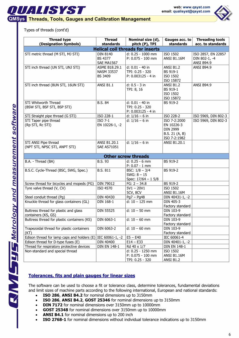
Types of threads (cont'd)
Thread type (Designation Symbols)
Thread standards
Nominal size (d), pitch (P), TPI
Gauges acc. to standards
Threading tools acc. to standards
Helical coil threads for inserts STI metric thread (M STI, MJ STI) DIN 8140
BS 4377 SAE MA1567
d: 0.25 - 1000 mm P: 0.075 - 100 mm
ISO 1502 ANSI B1.16M
ISO 2857, EN 22857 DIN 802-1, -4 ANSI B94.9
STI inch thread (UN STI, UNJ STI) ASME B18.29.1 NASM 33537 BS 3409
d: 0.01 - 40 in TPI: 0.25 - 320 P: 0.003125 - 4 in
ANSI B1.2 BS 919-1 ISO 1502 ISO 15872
ANSI B94.9
STI inch thread (8UN STI, 16UN STI)
ANSI B1.1 d: 0.5 - 3 in TPI: 8, 16
ANSI B1.2 BS 919-1 ISO 1502 ISO 15872
ANSI B94.9
STI Whitworth Thread (BSW STI, BSF STI, BSP STI)
B.S. 84 d: 0.01 - 40 in TPI: 0.25 - 320 P: 0.003125 - 4 in
BS 919-2
STI Straight pipe thread (G STI) ISO 228-1 d: 1/16 – 6 in ISO 228-2 ISO 5969, DIN 802-3 STI Taper pipe thread (Rp STI, Rc STI)
ISO 7-1 EN 10226-1, -2
d: 1/16 – 6 in ISO 7-2:2000 EN 10226-3 DIN 2999 B.S. 21 (A, B) ISO 7-2:1982
ISO 5969, DIN 802-3
STI ANSI Pipe thread (NPT STI, NPSC STI, ANPT STI)
ANSI B1.20.1 SAE AS71051
d: 1/16 – 6 in ANSI B1.20.1
Other screw threads B.A. - Thread (BA)
B.S. 93 d: 0.25 - 6 mm P: 0.07 - 1 mm
BS 919-2
B.S.C. Cycle-Thread (BSC, SWG, Spec.) B.S. 811 BSC: 1/8 – 3/4 SWG: 8 – 15 Spec: 17/64 – 1 5/8
BS 919-2
Screw thread for bicycles and mopeds (FG) DIN 79012 FG: 2 – 34.8 BS 919-2 Tyre valve thread (V, CV) ISO 4570 5V1 – 20V1
5CV, 8CV ISO 1502 ANSI B1.16M
Steel conduit thread (Pg) DIN 40430 Pg7 – Pg48 DIN 40431-1, -2 Knuckle thread for glass containers (GL) DIN 168-1 d: 10 – 125 mm DIN 405-3
Factory standard
Buttress thread for plastic and glass containers (KS, GS)
DIN 55525 d: 10 – 50 mm DIN 103-9 Factory standard
Buttress thread for plastic containers (KS) DIN 6063-1 d: 10 – 60 mm DIN 103-9 Factory standard
Trapezoidal thread for plastic containers (KT)
DIN 6063-2 d: 10 – 60 mm DIN 103-9 Factory standard
Edison thread for lamp caps and holders (E) IEC 60061-1, -2 E5 – E40 IEC 60061-4 Edison thread for D-type fuses (E) DIN 40400 E14 – E33 DIN 40401-1, -2 Thread for respiratory protective devices DIN EN 148-1 Rd 40 x 1/7 DIN EN 148-1 Non-standard and special thread d: 0.25 - 1250 mm
P: 0.075 - 100 mm TPI: 0.25 - 320
ISO 1502 ANSI B1.16M ANSI B1.2
Tolerances, fits and plain gauges for linear sizes The software can be used to choose a fit or tolerance class, determine tolerances, fundamental deviations and limit sizes of machine parts according to the following international, European and national standards:
• ISO 286, ANSI B4.2 for nominal dimensions up to 3150mm • ISO 286, ANSI B4.2, GOST 25346 for nominal dimensions up to 3150mm • DIN 7172 for nominal dimensions over 3150mm up to 10000mm • GOST 25348 for nominal dimensions over 3150mm up to 10000mm • ANSI B4.1 for nominal dimensions up to 200 inch • ISO 2768-1 for nominal dimensions without individual tolerance indications up to 3150mm
7
Threads, Tools, Gauges and Calibration Management
web: www.qsyst.com email: [email protected]
Database and techniques for calculating the nominal sizes and limit values of the following types of gauges have been included in the software:
• Plug gauges, ring gauges, snap gauges, checking plug gauges and setting plugs according to ISO/R 1938, DIN 7150-2, setting rings according to DIN 2250 for nominal sizes up to 500 mm and tolerance grade IT ≥ 5
• Plug gauges, ring gauges, snap gauges, master rings and master disks with class XXXX up to ZZ according to ASME B89.1.5, ASME B89.1.6 for nominal sizes from 0.0009 inches up to 19.69 inches.
• Plug gauges, ring gauges and setting plugs according to BS 969, setting rings acc. to BS 4064, BS 4065 for workpiece tolerances from 0.009 mm up to 3.2 mm, respectively from 0.00035 inches up to 0.12500 inches.
• Limit gauges (plug, ring and snap gauges) according to NF E 02-202, setting rings according to NF E 11-011 and setting plugs according NF E 11-012 for nominal sizes up to 500 mm and tolerance grade IT ≥ 5
• Acceptance gauges (plug, ring and snap gauges) according to NF E 02-205, setting rings according to NF E 11-011 and setting plugs according NF E 11-012 for nominal sizes up to 500 mm and tolerance grade IT ≥ 5
Thread cutting tools Editions Threads, Tools and Gauges and Threads, Gauges and Calibration Management comprise database and methods of calculating following types of threading tools:
• Cutting and forming taps; ground and cut threads • Threading tools for metric threads, unified threads, pipe threads, helical coil threads for inserts, etc. • Standard tolerance classes acc. to ISO 2857, EN 22857, GOST 16925: ISO 1, ISO 2, ISO 3, ISO 4 • Standard tolerance classes according to DIN 802-1, -4, -6: 4H, 6H, 6G, 7G • Standard tolerance classes according to ANSI B94.9: H, L, D, DU, Oversize, Undersize • Modified adjustable ISO tolerance classes for cutting taps: ISO 1X, ISO 2X, ISO 3X, ISO 4X • Modified adjustable ISO tolerance classes for forming taps: ISO 1X, ISO 2X, ISO 3X • Modified adjustable DIN tolerance classes: 4HX, 6HX, 6GX, 7GX • Input of non-standard allowances and tolerances • Taking into account the corrections for surface finishing of the threaded products.
Coefficients for calculating the fundamental deviation and tolerance of the pitch diameter and the minimum allowance of the major diameter can be adjusted individually for every modified ISO/DIN tolerance class.
8
Threads, Tools, Gauges and Calibration Management
web: www.qsyst.com email: [email protected]
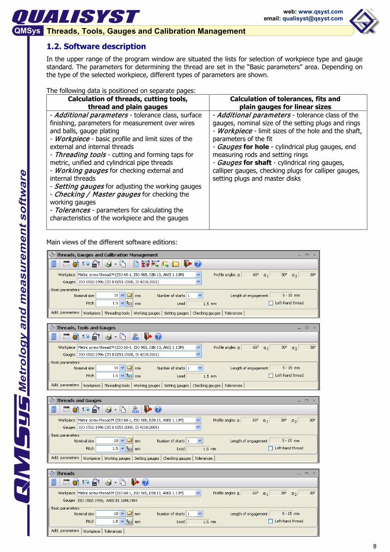
1.2. Software description In the upper range of the program window are situated the lists for selection of workpiece type and gauge standard. The parameters for determining the thread are set in the “Basic parameters” area. Depending on the type of the selected workpiece, different types of parameters are shown. The following data is positioned on separate pages:
Calculation of threads, cutting tools, thread and plain gauges
Calculation of tolerances, fits and plain gauges for linear sizes
- Additional parameters - tolerance class, surface finishing, parameters for measurement over wires and balls, gauge plating - Workpiece - basic profile and limit sizes of the external and internal threads - Threading tools - cutting and forming taps for metric, unified and cylindrical pipe threads - Working gauges for checking external and internal threads - Setting gauges for adjusting the working gauges - Checking / Master gauges for checking the working gauges - Tolerances - parameters for calculating the characteristics of the workpiece and the gauges
- Additional parameters - tolerance class of the gauges, nominal size of the setting plugs and rings - Workpiece - limit sizes of the hole and the shaft, parameters of the fit - Gauges for hole - cylindrical plug gauges, end measuring rods and setting rings - Gauges for shaft - cylindrical ring gauges, calliper gauges, checking plugs for calliper gauges, setting plugs and master disks
Main views of the different software editions:
9
Threads, Tools, Gauges and Calibration Management
web: www.qsyst.com email: [email protected]
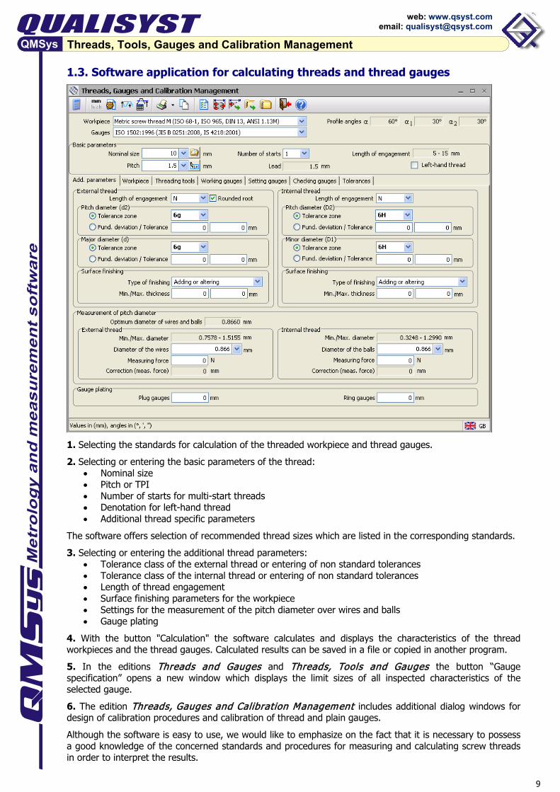
1.3. Software application for calculating threads and thread gauges
1. Selecting the standards for calculation of the threaded workpiece and thread gauges. 2. Selecting or entering the basic parameters of the thread:
• Nominal size • Pitch or TPI • Number of starts for multi-start threads • Denotation for left-hand thread • Additional thread specific parameters
The software offers selection of recommended thread sizes which are listed in the corresponding standards. 3. Selecting or entering the additional thread parameters:
• Tolerance class of the external thread or entering of non standard tolerances • Tolerance class of the internal thread or entering of non standard tolerances • Length of thread engagement • Surface finishing parameters for the workpiece • Settings for the measurement of the pitch diameter over wires and balls • Gauge plating
4. With the button "Calculation" the software calculates and displays the characteristics of the thread workpieces and the thread gauges. Calculated results can be saved in a file or copied in another program. 5. In the editions Threads and Gauges and Threads, Tools and Gauges the button “Gauge specification” opens a new window which displays the limit sizes of all inspected characteristics of the selected gauge. 6. The edition Threads, Gauges and Calibration Management includes additional dialog windows for design of calibration procedures and calibration of thread and plain gauges. Although the software is easy to use, we would like to emphasize on the fact that it is necessary to possess a good knowledge of the concerned standards and procedures for measuring and calculating screw threads in order to interpret the results.

10
Threads, Tools, Gauges and Calibration Management
web: www.qsyst.com email: [email protected]
1.4. Software application for calculating plain gauges for linear sizes 1. Selecting the standards for calculating the workpiece and the plain gauges. 2. Selecting or entering the basic parameters of the workpiece:
• Nominal size • Tolerance class for the hole and/or shaft for workpieces with standard tolerances • Limit sizes or limit deviations for workpieces with non-standard tolerances
3. Selecting or entering the additional gauge parameters depending on the selected gauge standard:
• Size of the setting ring and plugs - selection of one of the workpiece sizes: nominal, mean, maximum, minimum.
• Tolerance class of ISO setting ring - JS3 or JS4 • Tolerance class plain limit gauges, master rings and master disks according to ASME B89.1.5, ASME
B89.1.6: XXXX, XXX, XX, X, Y, Z or ZZ. The software offers automatically the suitable gauge class with gauge tolerance under 5% of the workpiece tolerance
• Tolerance class setting ring according to BS 4064, BS 4065: AA, A or B. 4. With the button "Calculation" the software calculates tolerances, limit deviations and limit sizes of the workpiece and gauges. The location of tolerance zones is visualized graphically as well, depending on selected page of parameters of the workpiece or gauges. 1.5. Printout of the calculated thread workpiece, threading tools and gauges When custom templates are not specified, the software prints all data of the calculated thread and thread gauges in the integrated templates in RTF format. Specifications of the plain gauges for linear sizes can be exported in files in TXT, RTF, XLS or HTML format. Printout in the program can also be made by configurable templates in TXT, RTF or XLS. Basis for the custom templates are the integrated in the software templates, which can be opened in RTF format and include the codes of all data fields for the selected thread. Custom templates are adjusted separately for each thread, respectively several templates per thread type can be selected.
11
Threads, Tools, Gauges and Calibration Management
web: www.qsyst.com email: [email protected]
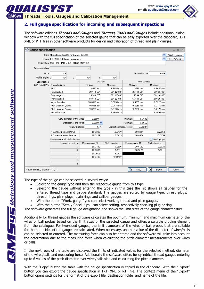
2. Full gauge specification for incoming and subsequent inspections The software editions Threads and Gauges and Threads, Tools and Gauges include additional dialog window with the full specification of the selected gauge that can be easy exported over the clipboard, TXT, XML or RTF files in other software products for design and calibration of thread and plain gauges.
The type of the gauge can be selected in several ways:
• Selecting the gauge type and then the respective gauge from this type • Selecting the gauge without entering the type - in this case the list shows all gauges for the
entered thread type and gauge standard. The gauges are sorted by gauge type: thread plugs; thread rings, plain plugs; plain rings and calliper gauges.
• With the button “Work. gauge” you can select working thread and plain gauges. • With the button “Sett. / Check.” you can select setting, respectively checking plug or ring.
The software generates the full gauge designation and shows the limit sizes of the gauge characteristics. Additionally for thread gauges the software calculates the optimum, minimum and maximum diameter of the wires or ball probes based on the limit sizes of the selected gauge and offers a suitable probing element from the catalogue. For two-sided gauges, the limit diameters of the wires or ball probes that are suitable for the both sides of the gauge are calculated. When necessary, another value of the diameter of wires/balls can be selected or entered. The measuring force can also be entered and the software will take into account the deformation due to the measuring force when calculating the pitch diameter measurements over wires or balls. In the next rows of the table are displayed the limits of indicated values for the selected method, diameter of the wires/balls and measuring force. Additionally the software offers for cylindrical thread gauges entering up to 6 values of the pitch diameter over wires/balls side and calculating the pitch diameter. With the “Copy” button the table with the gauge specification is copied in the clipboard. With the “Export” button you can export the gauge specification in TXT, XML or RTF file. The context menu of the “Export” button opens settings for the format of the export file, destination folder and name of the file.

12
Threads, Tools, Gauges and Calibration Management
web: www.qsyst.com email: [email protected]
For taper gauges the software displays additional information concerning taper, position of the gauge plane and checking with master gauges.
13
Threads, Tools, Gauges and Calibration Management
web: www.qsyst.com email: [email protected]
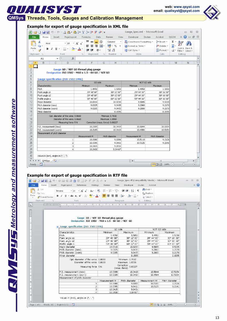
Example for export of gauge specification in XML file
Example for export of gauge specification in RTF file
14
Threads, Tools, Gauges and Calibration Management
web: www.qsyst.com email: [email protected]
3. Calibration management of thread and plain gauges The software edition QMSys Threads, Gauges and Calibration Management includes additional dialog windows for the purpose of the calibration of thread and plain gauges:
• Calibration settings - this window includes several pages for definition of calibration procedures for the respective types of gauges, catalogues for the measuring instruments, wire sets and ball probe sets, and additional program settings concerning the calibration process.
• Calibration - starts the gauge calibration; the necessary workpiece and gauges must be calculated first.
• Calibration of special gauges - with this button is started the calibration of special gauges, which limit sizes can be entered manually.
• Unfinished calibrations - opens a table with unfinished calibrations that can be continued or deleted.
• Calibration of registered gauges - in this window is started the calibration of gauges that are already calibrated with the software and the results are saved in the calibration history. The software offers several filters for the easy and quick selection of the gauge - client name and number, gauge identification number, calibration certificate number, order number, date of calibration.
• Calibration history - complete archive of the calibrations, including gauge identification, specification and calibration data.
3.1. Calibration procedures, catalogues and additional settings The main part of the calibration system is the preparation of calibration procedures for the different types of gauges. The software offers additional catalogues to assist and facilitate the activities on calibration of thread and plain gauges:
• Catalogue of the measuring instruments and machines • Catalogue of the measuring wire sets and ball probe sets • Additional catalogues for instrument types, gauges manufacturers, clients, places of calibration and
inspector names. • Settings for additional data, entered before and after the measurements
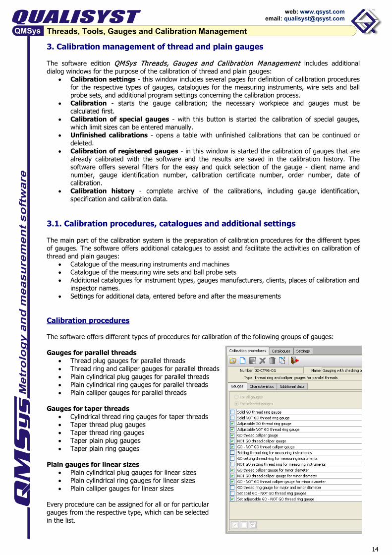
Calibration procedures The software offers different types of procedures for calibration of the following groups of gauges: Gauges for parallel threads
• Thread plug gauges for parallel threads • Thread ring and calliper gauges for parallel threads • Plain cylindrical plug gauges for parallel threads • Plain cylindrical ring gauges for parallel threads • Plain calliper gauges for parallel threads
Gauges for taper threads
• Cylindrical thread ring gauges for taper threads • Taper thread plug gauges • Taper thread ring gauges • Taper plain plug gauges • Taper plain ring gauges
Plain gauges for linear sizes
• Plain cylindrical plug gauges for linear sizes • Plain cylindrical ring gauges for linear sizes • Plain calliper gauges for linear sizes
Every procedure can be assigned for all or for particular gauges from the respective type, which can be selected in the list.
15
Threads, Tools, Gauges and Calibration Management
web: www.qsyst.com email: [email protected]
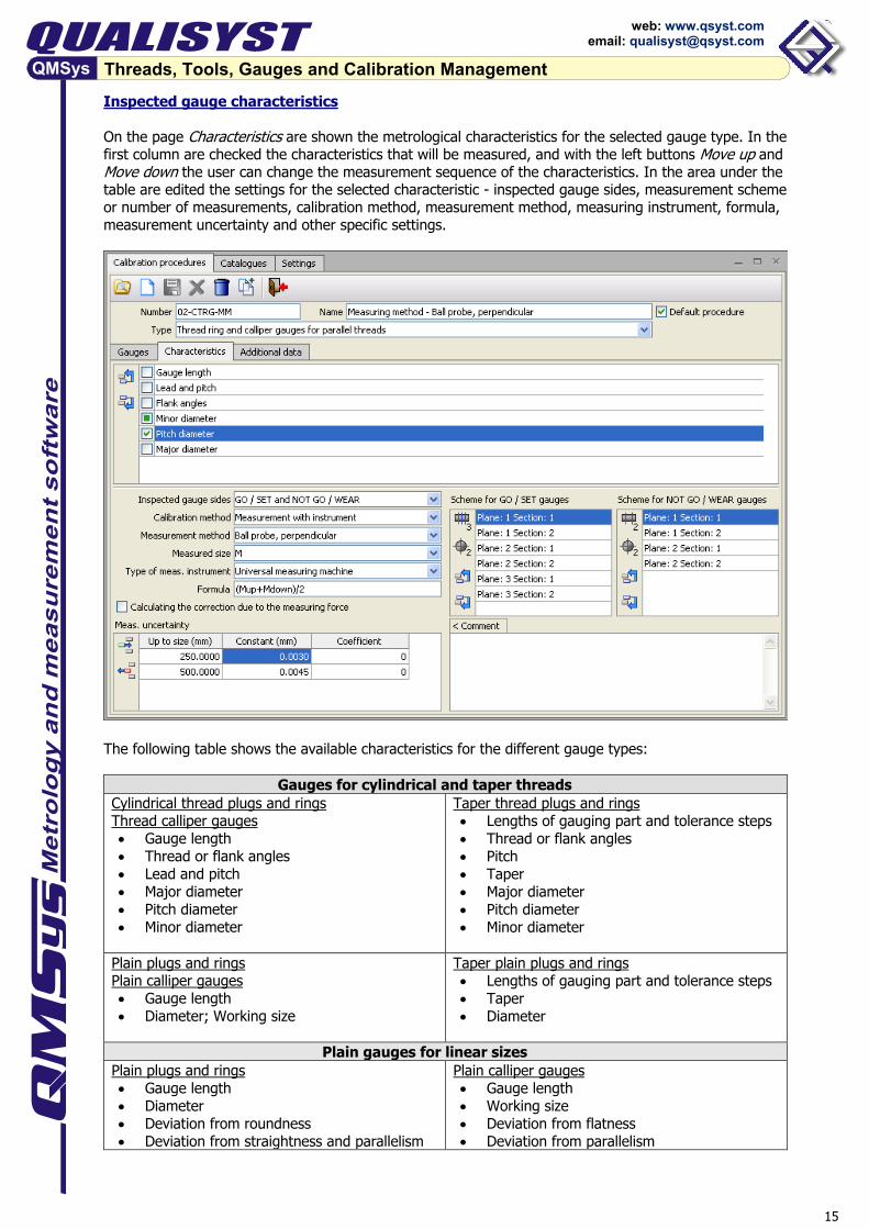
Inspected gauge characteristics On the page Characteristics are shown the metrological characteristics for the selected gauge type. In the first column are checked the characteristics that will be measured, and with the left buttons Move up and Move down the user can change the measurement sequence of the characteristics. In the area under the table are edited the settings for the selected characteristic - inspected gauge sides, measurement scheme or number of measurements, calibration method, measurement method, measuring instrument, formula, measurement uncertainty and other specific settings.
The following table shows the available characteristics for the different gauge types:
Gauges for cylindrical and taper threads Cylindrical thread plugs and rings Thread calliper gauges • Gauge length • Thread or flank angles • Lead and pitch • Major diameter • Pitch diameter • Minor diameter
Taper thread plugs and rings • Lengths of gauging part and tolerance steps • Thread or flank angles • Pitch • Taper • Major diameter • Pitch diameter • Minor diameter
Plain plugs and rings Plain calliper gauges • Gauge length • Diameter; Working size
Taper plain plugs and rings • Lengths of gauging part and tolerance steps • Taper • Diameter
Plain gauges for linear sizes
Plain plugs and rings • Gauge length • Diameter • Deviation from roundness • Deviation from straightness and parallelism
Plain calliper gauges • Gauge length • Working size • Deviation from flatness • Deviation from parallelism
16
Threads, Tools, Gauges and Calibration Management
web: www.qsyst.com email: [email protected]
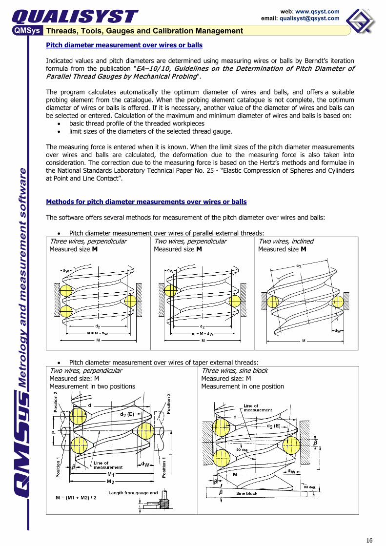
Pitch diameter measurement over wires or balls Indicated values and pitch diameters are determined using measuring wires or balls by Berndt’s iteration formula from the publication "EA–10/ 10, Guidelines on the Determination of P itch Diameter of Parallel Thread Gauges by Mechanical Probing". The program calculates automatically the optimum diameter of wires and balls, and offers a suitable probing element from the catalogue. When the probing element catalogue is not complete, the optimum diameter of wires or balls is offered. If it is necessary, another value of the diameter of wires and balls can be selected or entered. Calculation of the maximum and minimum diameter of wires and balls is based on:
• basic thread profile of the threaded workpieces • limit sizes of the diameters of the selected thread gauge.
The measuring force is entered when it is known. When the limit sizes of the pitch diameter measurements over wires and balls are calculated, the deformation due to the measuring force is also taken into consideration. The correction due to the measuring force is based on the Hertz’s methods and formulae in the National Standards Laboratory Technical Paper No. 25 - “Elastic Compression of Spheres and Cylinders at Point and Line Contact”. Methods for pitch diameter measurements over wires or balls The software offers several methods for measurement of the pitch diameter over wires and balls:
• Pitch diameter measurement over wires of parallel external threads: Three wires, perpendicular Measured size M
Two wires, perpendicular Measured size M
Two wires, inclined Measured size M
• Pitch diameter measurement over wires of taper external threads: Two wires, perpendicular Measured size: M Measurement in two positions
Three wires, sine block Measured size: M Measurement in one position

17
Threads, Tools, Gauges and Calibration Management
web: www.qsyst.com email: [email protected]
• Pitch diameter measurement over balls of parallel internal threads: Ball probe, perpendicular Measured size: M or ΔL Measurement in two positions
Measurement in one position
Ball probe, inclined Measured size: M
• Pitch diameter measurement over balls of taper internal threads:
Ball probe, perpendicular Measured size: M or ΔL Measurement in two positions
18
Threads, Tools, Gauges and Calibration Management
web: www.qsyst.com email: [email protected]
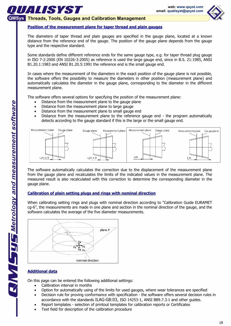
Position of the measurement plane for taper thread and plain gauges The diameters of taper thread and plain gauges are specified in the gauge plane, located at a known distance from the reference end of the gauge. The position of the gauge plane depends from the gauge type and the respective standard. Some standards define different reference ends for the same gauge type, e.g. for taper thread plug gauge in ISO 7-2:2000 (EN 10226-3:2005) as reference is used the large gauge end, since in B.S. 21:1985, ANSI B1.20.1:1983 and ANSI B1.20.5:1991 the reference end is the small gauge end. In cases where the measurement of the diameters in the exact position of the gauge plane is not possible, the software offers the possibility to measure the diameters in other position (measurement plane) and automatically calculates the diameter in the gauge plane, corresponding to the diameter in the different measurement plane. The software offers several options for specifying the position of the measurement plane:
• Distance from the measurement plane to the gauge plane • Distance from the measurement plane to large gauge • Distance from the measurement plane to small gauge end • Distance from the measurement plane to the reference gauge end - the program automatically
detects according to the gauge standard if this is the large or the small gauge end.
The software automatically calculates the correction due to the displacement of the measurement plane from the gauge plane and recalculates the limits of the indicated values in the measurement plane. The measured result is also recalculated with this correction to determine the corresponding diameter in the gauge plane. Calibration of plain setting plugs and rings with nominal direction When calibrating setting rings and plugs with nominal direction according to “Calibration Guide EURAMET cg-6”, the measurements are made in one plane and section in the nominal direction of the gauge, and the software calculates the average of the five diameter measurements.
Additional data On this page can be entered the following additional settings:
• Calibration interval in months • Option for automatically using of the limits for used gauges, where wear tolerances are specified • Decision rule for proving conformance with specification - the software offers several decision rules in
accordance with the standards ILAG-G8:03, ISO 14253-1, ANSI B89.7.3.1 and other guides. • Report templates - selection of printout templates for calibration reports or Certificates • Text field for description of the calibration procedure
19
Threads, Tools, Gauges and Calibration Management
web: www.qsyst.com email: [email protected]
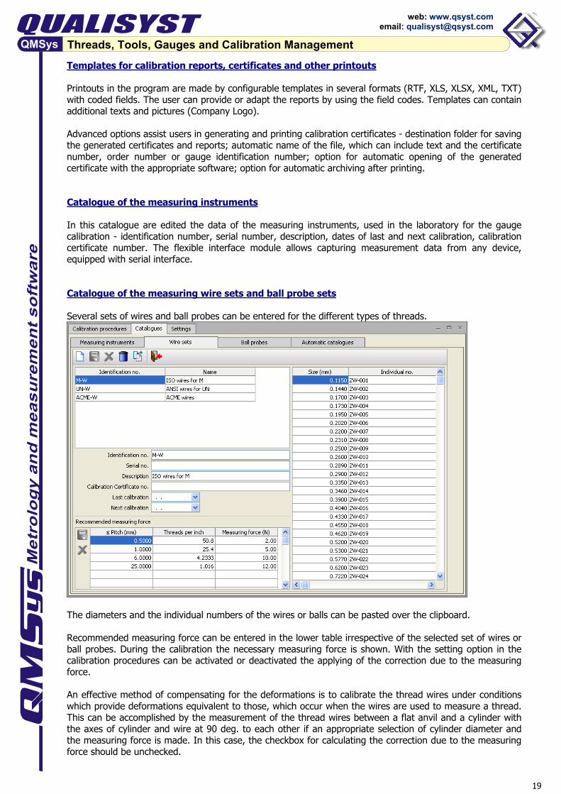
Templates for calibration reports, certificates and other printouts Printouts in the program are made by configurable templates in several formats (RTF, XLS, XLSX, XML, TXT) with coded fields. The user can provide or adapt the reports by using the field codes. Templates can contain additional texts and pictures (Company Logo). Advanced options assist users in generating and printing calibration certificates - destination folder for saving the generated certificates and reports; automatic name of the file, which can include text and the certificate number, order number or gauge identification number; option for automatic opening of the generated certificate with the appropriate software; option for automatic archiving after printing. Catalogue of the measuring instruments In this catalogue are edited the data of the measuring instruments, used in the laboratory for the gauge calibration - identification number, serial number, description, dates of last and next calibration, calibration certificate number. The flexible interface module allows capturing measurement data from any device, equipped with serial interface. Catalogue of the measuring wire sets and ball probe sets Several sets of wires and ball probes can be entered for the different types of threads.
The diameters and the individual numbers of the wires or balls can be pasted over the clipboard. Recommended measuring force can be entered in the lower table irrespective of the selected set of wires or ball probes. During the calibration the necessary measuring force is shown. With the setting option in the calibration procedures can be activated or deactivated the applying of the correction due to the measuring force. An effective method of compensating for the deformations is to calibrate the thread wires under conditions which provide deformations equivalent to those, which occur when the wires are used to measure a thread. This can be accomplished by the measurement of the thread wires between a flat anvil and a cylinder with the axes of cylinder and wire at 90 deg. to each other if an appropriate selection of cylinder diameter and the measuring force is made. In this case, the checkbox for calculating the correction due to the measuring force should be unchecked.
20
Threads, Tools, Gauges and Calibration Management
web: www.qsyst.com email: [email protected]
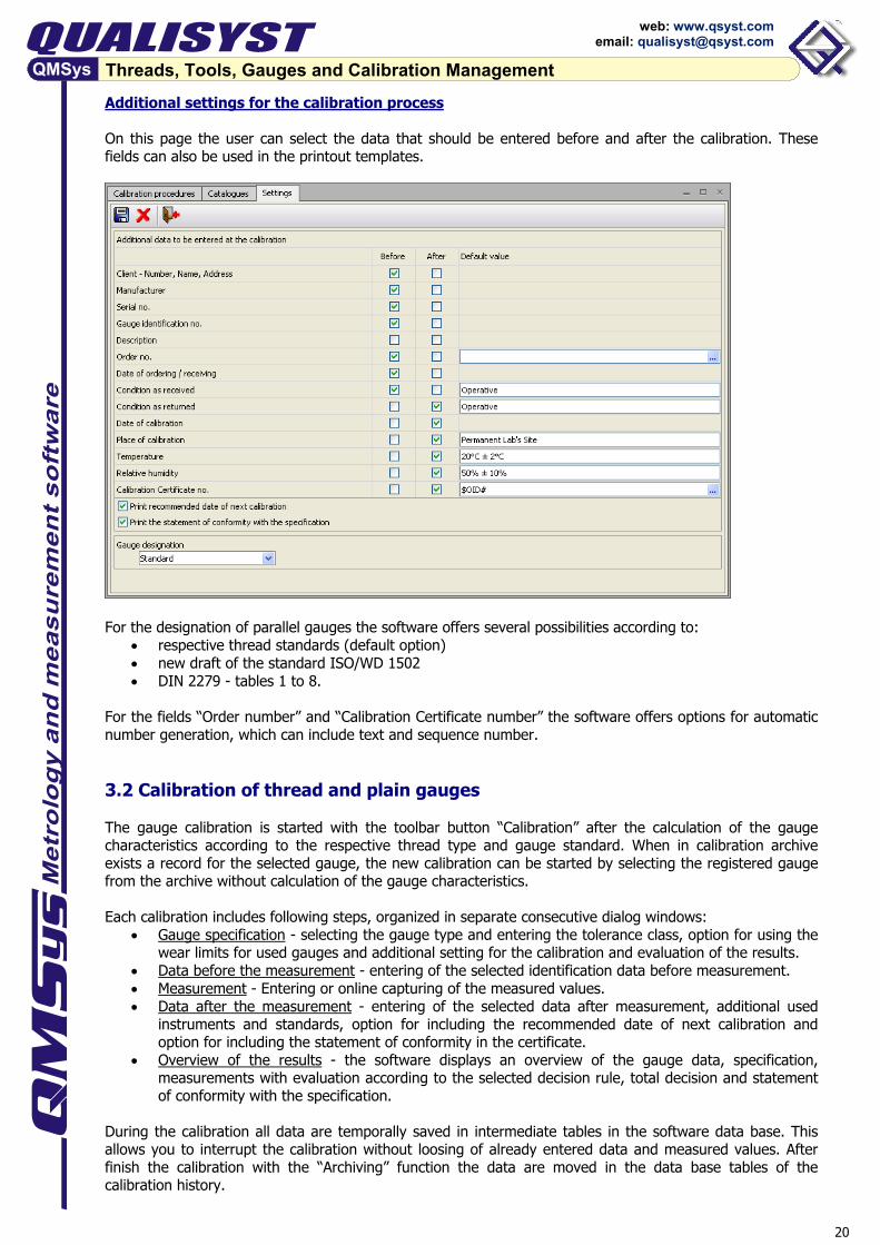
Additional settings for the calibration process On this page the user can select the data that should be entered before and after the calibration. These fields can also be used in the printout templates.
For the designation of parallel gauges the software offers several possibilities according to:
• respective thread standards (default option) • new draft of the standard ISO/WD 1502 • DIN 2279 - tables 1 to 8.
For the fields “Order number” and “Calibration Certificate number” the software offers options for automatic number generation, which can include text and sequence number. 3.2 Calibration of thread and plain gauges The gauge calibration is started with the toolbar button “Calibration” after the calculation of the gauge characteristics according to the respective thread type and gauge standard. When in calibration archive exists a record for the selected gauge, the new calibration can be started by selecting the registered gauge from the archive without calculation of the gauge characteristics. Each calibration includes following steps, organized in separate consecutive dialog windows:
• Gauge specification - selecting the gauge type and entering the tolerance class, option for using the wear limits for used gauges and additional setting for the calibration and evaluation of the results.
• Data before the measurement - entering of the selected identification data before measurement. • Measurement - Entering or online capturing of the measured values. • Data after the measurement - entering of the selected data after measurement, additional used
instruments and standards, option for including the recommended date of next calibration and option for including the statement of conformity in the certificate.
• Overview of the results - the software displays an overview of the gauge data, specification, measurements with evaluation according to the selected decision rule, total decision and statement of conformity with the specification.
During the calibration all data are temporally saved in intermediate tables in the software data base. This allows you to interrupt the calibration without loosing of already entered data and measured values. After finish the calibration with the “Archiving” function the data are moved in the data base tables of the calibration history.
21
Threads, Tools, Gauges and Calibration Management
web: www.qsyst.com email: [email protected]
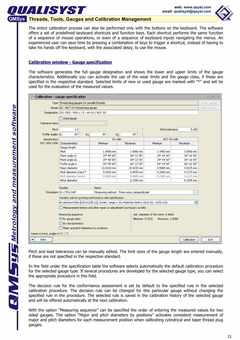
The entire calibration process can also be performed only with the buttons on the keyboard. The software offers a set of predefined keyboard shortcuts and function keys. Each shortcut performs the same function of a sequence of mouse operations, or even of a sequence of keyboard inputs navigating the menus. An experienced user can save time by pressing a combination of keys to trigger a shortcut, instead of having to take his hands off the keyboard, with the associated delay, to use the mouse. Calibration window - Gauge specification The software generates the full gauge designation and shows the lower and upper limits of the gauge characteristics. Additionally you can activate the use of the wear limits and the gauge class, if these are specified in the respective standard. Selected limits of new or used gauge are marked with “*” and will be used for the evaluation of the measured values.
Pitch and lead tolerances can be manually edited. The limit sizes of the gauge length are entered manually, if these are not specified in the respective standard. In the field under the specification table the software selects automatically the default calibration procedure for the selected gauge type. If several procedures are developed for the selected gauge type, you can select the appropriate procedure in this field. The decision rule for the conformance assessment is set by default to the specified rule in the selected calibration procedure. The decision rule can be changed for this particular gauge without changing the specified rule in the procedure. The selected rule is saved in the calibration history of the selected gauge and will be offered automatically at the next calibration. With the option “Measuring sequence” can be specified the order of entering the measured values for two sided gauges. The option “Major and pitch diameters by positions” activates consistent measurement of major and pitch diameters for each measurement position when calibrating cylindrical and taper thread plug gauges.
22
Threads, Tools, Gauges and Calibration Management
web: www.qsyst.com email: [email protected]
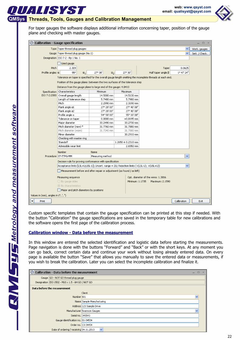
For taper gauges the software displays additional information concerning taper, position of the gauge plane and checking with master gauges.
Custom specific templates that contain the gauge specification can be printed at this step if needed. With the button “Calibration” the gauge specifications are saved in the temporary table for new calibrations and the software opens the first page of the calibration process. Calibration window - Data before the measurement In this window are entered the selected identification and logistic data before starting the measurements. Page navigation is done with the buttons “Forward” and “Back” or with the short keys. At any moment you can go back, correct certain data and continue your work without losing already entered data. On every page is available the button “Save” that allows you manually to save the entered data or measurements, if you wish to break the calibration. Later you can select the incomplete calibration and finalize it.
23
Threads, Tools, Gauges and Calibration Management
web: www.qsyst.com email: [email protected]
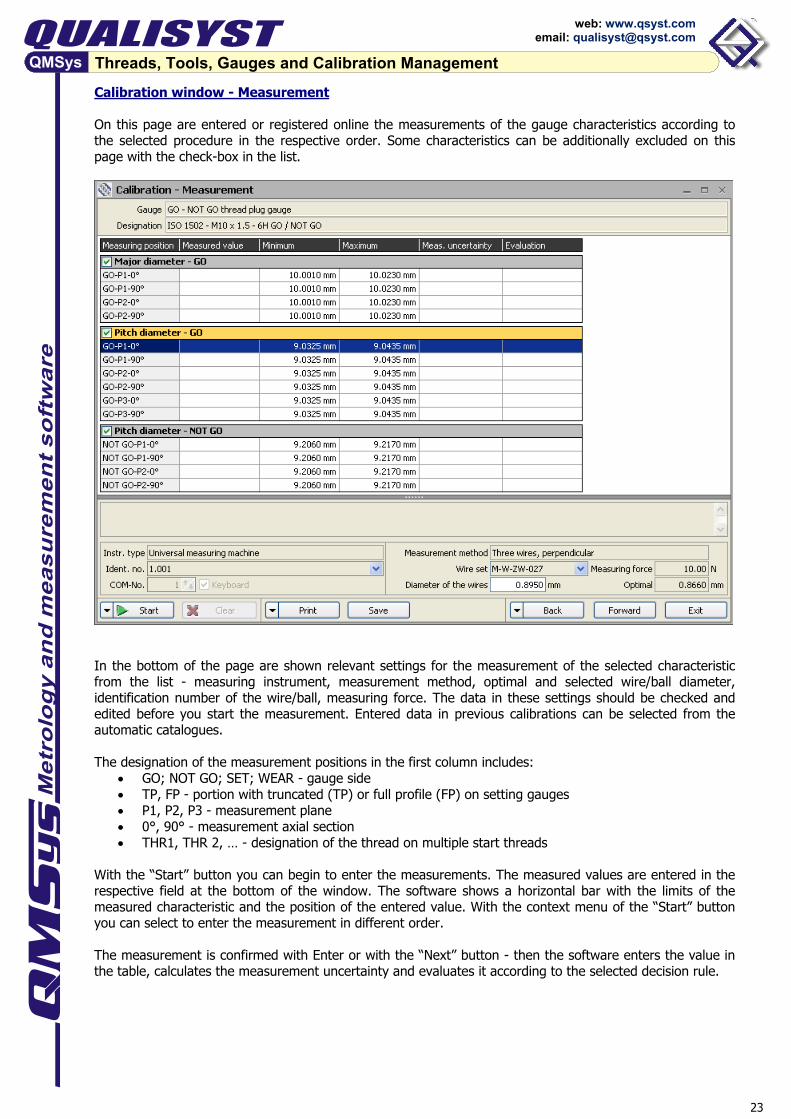
Calibration window - Measurement On this page are entered or registered online the measurements of the gauge characteristics according to the selected procedure in the respective order. Some characteristics can be additionally excluded on this page with the check-box in the list.
In the bottom of the page are shown relevant settings for the measurement of the selected characteristic from the list - measuring instrument, measurement method, optimal and selected wire/ball diameter, identification number of the wire/ball, measuring force. The data in these settings should be checked and edited before you start the measurement. Entered data in previous calibrations can be selected from the automatic catalogues. The designation of the measurement positions in the first column includes:
• GO; NOT GO; SET; WEAR - gauge side • TP, FP - portion with truncated (TP) or full profile (FP) on setting gauges • P1, P2, P3 - measurement plane • 0°, 90° - measurement axial section • THR1, THR 2, … - designation of the thread on multiple start threads
With the “Start” button you can begin to enter the measurements. The measured values are entered in the respective field at the bottom of the window. The software shows a horizontal bar with the limits of the measured characteristic and the position of the entered value. With the context menu of the “Start” button you can select to enter the measurement in different order. The measurement is confirmed with Enter or with the “Next” button - then the software enters the value in the table, calculates the measurement uncertainty and evaluates it according to the selected decision rule.
24
Threads, Tools, Gauges and Calibration Management
web: www.qsyst.com email: [email protected]
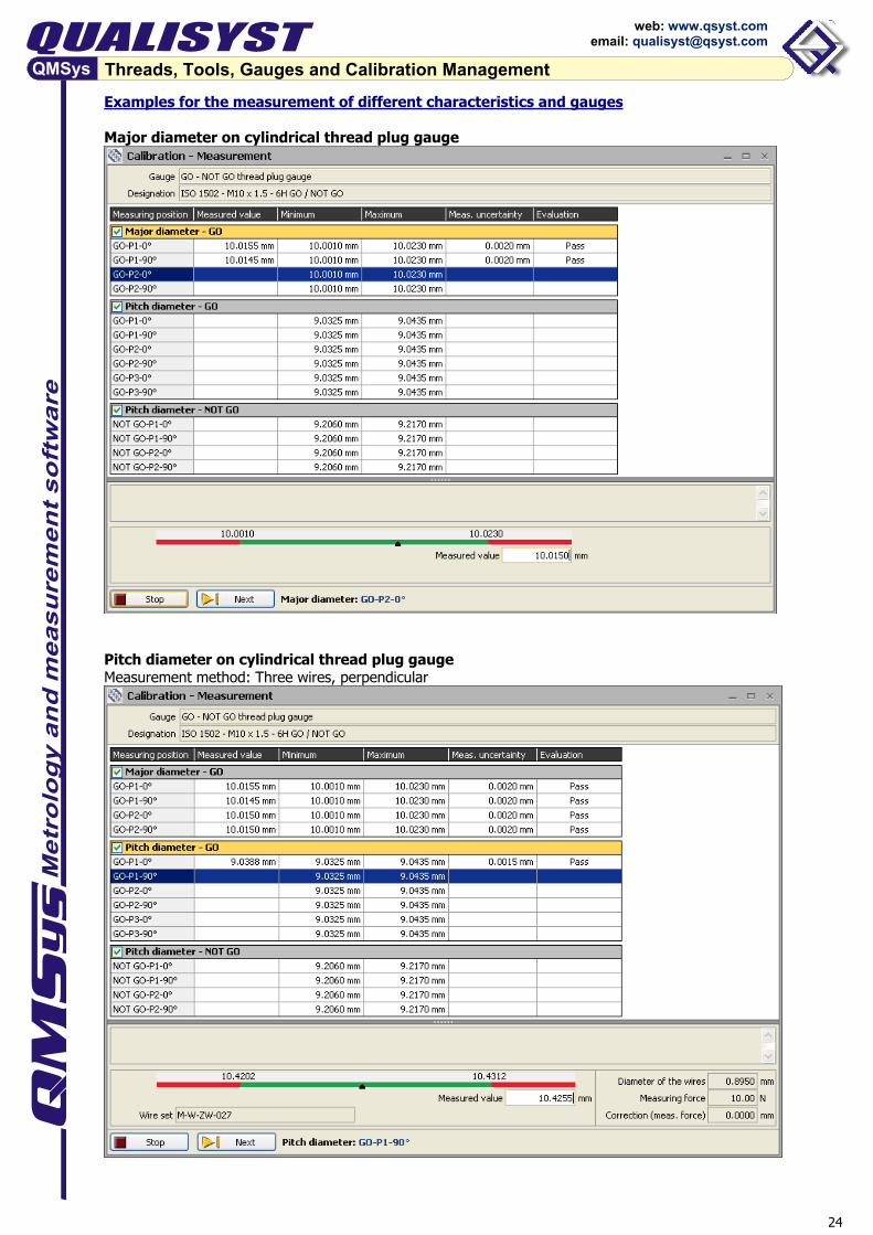
Examples for the measurement of different characteristics and gauges Major diameter on cylindrical thread plug gauge
Pitch diameter on cylindrical thread plug gauge Measurement method: Three wires, perpendicular
25
Threads, Tools, Gauges and Calibration Management
web: www.qsyst.com email: [email protected]
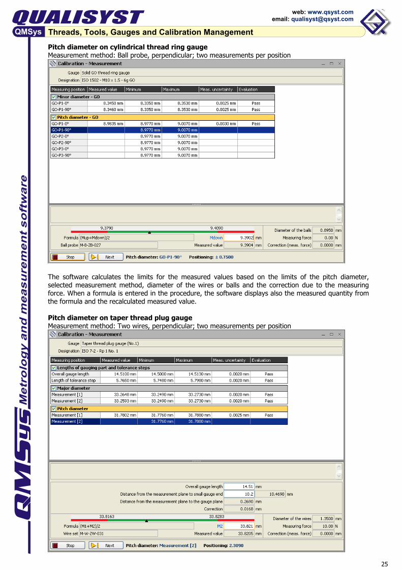
Pitch diameter on cylindrical thread ring gauge Measurement method: Ball probe, perpendicular; two measurements per position
The software calculates the limits for the measured values based on the limits of the pitch diameter, selected measurement method, diameter of the wires or balls and the correction due to the measuring force. When a formula is entered in the procedure, the software displays also the measured quantity from the formula and the recalculated measured value. Pitch diameter on taper thread plug gauge Measurement method: Two wires, perpendicular; two measurements per position
26
Threads, Tools, Gauges and Calibration Management
web: www.qsyst.com email: [email protected]
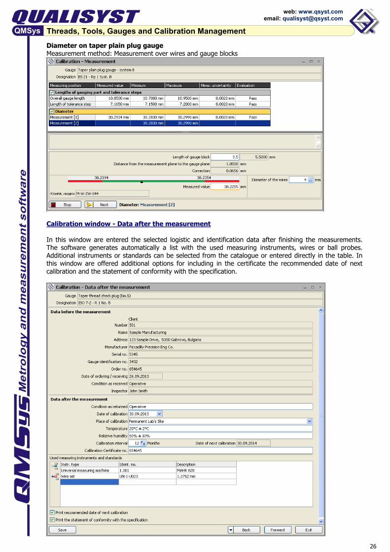
Diameter on taper plain plug gauge Measurement method: Measurement over wires and gauge blocks
Calibration window - Data after the measurement In this window are entered the selected logistic and identification data after finishing the measurements. The software generates automatically a list with the used measuring instruments, wires or ball probes. Additional instruments or standards can be selected from the catalogue or entered directly in the table. In this window are offered additional options for including in the certificate the recommended date of next calibration and the statement of conformity with the specification.

27
Threads, Tools, Gauges and Calibration Management
web: www.qsyst.com email: [email protected]
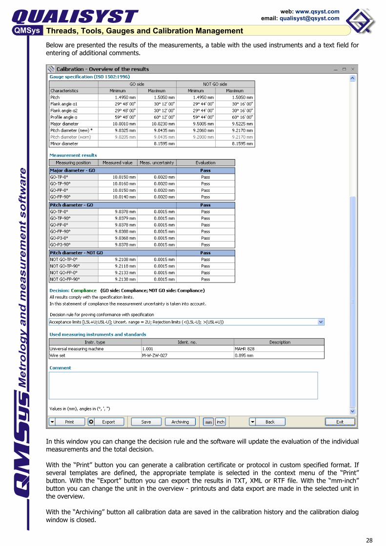
Calibration window - Overview of the results In the final calibration window the software displays an overview of the gauge data, specification, measurements with evaluation according to the selected decision rule, total decision and statement of conformity with the specification. On the top of the window you can find the gauge designation, identification and additional calibration data, calibration procedure and gauge specification.
28
Threads, Tools, Gauges and Calibration Management
web: www.qsyst.com email: [email protected]
Below are presented the results of the measurements, a table with the used instruments and a text field for entering of additional comments.
In this window you can change the decision rule and the software will update the evaluation of the individual measurements and the total decision. With the “Print” button you can generate a calibration certificate or protocol in custom specified format. If several templates are defined, the appropriate template is selected in the context menu of the “Print” button. With the “Export” button you can export the results in TXT, XML or RTF file. With the “mm-inch” button you can change the unit in the overview - printouts and data export are made in the selected unit in the overview. With the “Archiving” button all calibration data are saved in the calibration history and the calibration dialog window is closed.
29
Threads, Tools, Gauges and Calibration Management
web: www.qsyst.com email: [email protected]
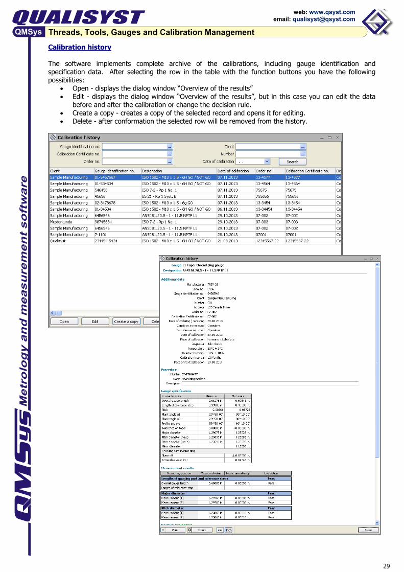
Calibration history The software implements complete archive of the calibrations, including gauge identification and specification data. After selecting the row in the table with the function buttons you have the following possibilities:
• Open - displays the dialog window “Overview of the results” • Edit - displays the dialog window “Overview of the results”, but in this case you can edit the data
before and after the calibration or change the decision rule. • Create a copy - creates a copy of the selected record and opens it for editing. • Delete - after conformation the selected row will be removed from the history.

30
Threads, Tools, Gauges and Calibration Management
web: www.qsyst.com email: [email protected]
3.3 Examples for Calibration Certificates ISO-Certificate in MS Excel format
31
Threads, Tools, Gauges and Calibration Management
web: www.qsyst.com email: [email protected]
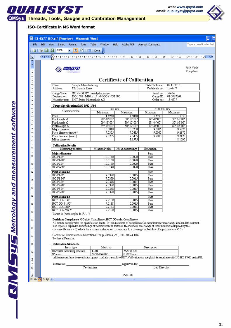
ISO-Certificate in MS Word format
32
Threads, Tools, Gauges and Calibration Management
web: www.qsyst.com email: [email protected]
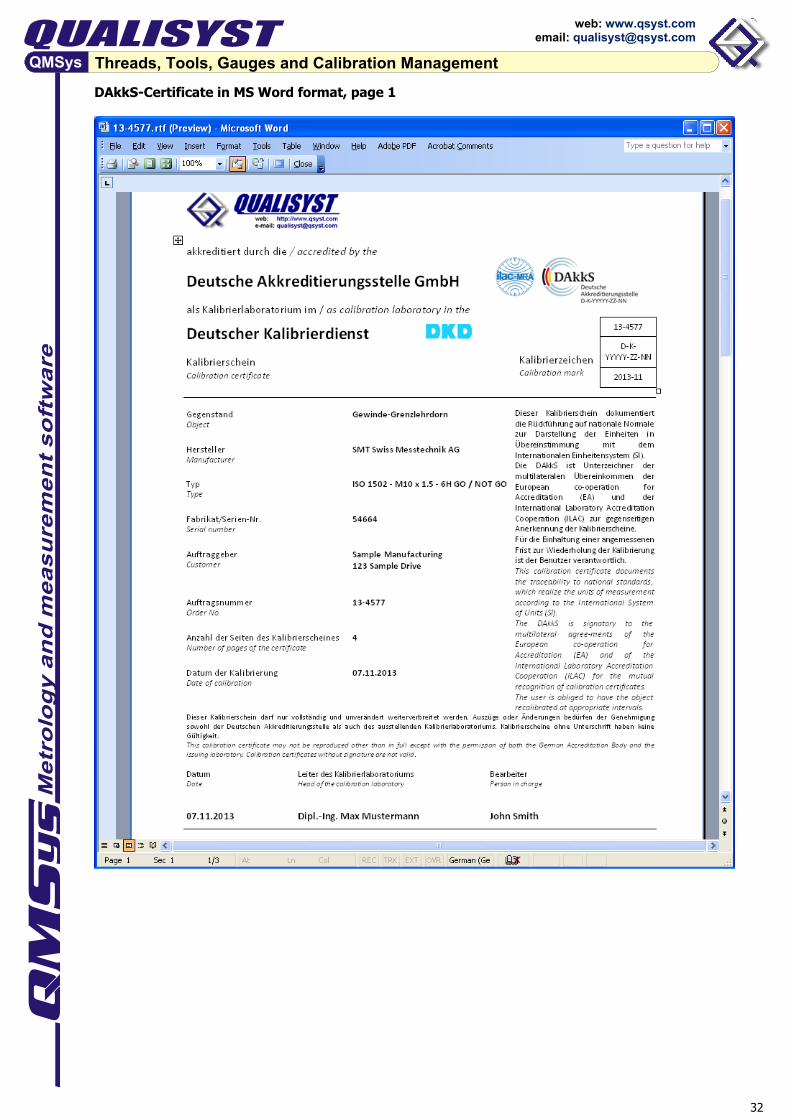
DAkkS-Certificate in MS Word format, page 1

33
Threads, Tools, Gauges and Calibration Management
web: www.qsyst.com email: [email protected]
DAkkS-Certificate in MS Word format, pages 2 and 3