Embed Size (px)
Citation preview

SOFTWARE ENGINEERING

LECTURE-29
Software Development Life Cycle (SDLC)

SOFTWARE DEVELOPMENT LIFE
CYCLE (SDLC) “You’ve got to be very careful if you don’t know where you’re going, because you might not get there.”

CAPABILITY MATURITY MODEL (CMM)
A bench-mark for measuring the maturity of an
organization’s software process
CMM defines 5 levels of process maturity based on
certain Key Process Areas (KPA)

CMM LEVELS Level 5 – Optimizing (< 1%)
-- process change management
-- technology change management
-- defect prevention
Level 4 – Managed (< 5%) -- software quality management
-- quantitative process management
Level 3 – Defined (< 10%) -- peer reviews
-- intergroup coordination
-- software product engineering
-- integrated software management
-- training program
-- organization process definition
-- organization process focus
Level 2 – Repeatable (~ 15%) -- software configuration management
-- software quality assurance
-- software project tracking and oversight
-- software project planning
-- requirements management
Level 1 – Initial (~ 70%)

SDLC MODEL
A framework that describes the activities performed
at each stage of a software development project.

WATERFALL MODEL Requirements – defines
needed information, function,
behavior, performance and
interfaces.
Design – data structures,
software architecture, interface
representations, algorithmic
details.
Implementation – source code,
database, user documentation,
testing.

WATERFALL STRENGTHS
Easy to understand, easy to use
Provides structure to inexperienced staff
Milestones are well understood
Sets requirements stability
Good for management control (plan, staff,
track)
Works well when quality is more important
than cost or schedule

WATERFALL DEFICIENCIES All requirements must be known upfront
Deliverables created for each phase are considered frozen – inhibits flexibility
Can give a false impression of progress
Does not reflect problem-solving nature of software development – iterations of phases
Integration is one big bang at the end
Little opportunity for customer to preview the system (until it may be too late)

WHEN TO USE THE WATERFALL
MODEL
Requirements are very well known
Product definition is stable
Technology is understood
New version of an existing product
Porting an existing product to a new platform.

V-SHAPED SDLC MODEL
A variant of the Waterfall
that emphasizes the
verification and validation
of the product.
Testing of the product is
planned in parallel with a
corresponding phase of
development

V-SHAPED STEPS Project and Requirements
Planning – allocate resources
Product Requirements and Specification Analysis – complete specification of the software system
Architecture or High-Level Design – defines how software functions fulfill the design
Detailed Design – develop algorithms for each architectural component
Production, operation and maintenance – provide for enhancement and corrections
System and acceptance testing – check the entire software system in its environment
Integration and Testing – check that modules interconnect correctly
Unit testing – check that each module acts as expected
Coding – transform algorithms into software

V-SHAPED STRENGTHS
Emphasize planning for verification and validation
of the product in early stages of product
development
Each deliverable must be testable
Project management can track progress by
milestones
Easy to use

V-SHAPED WEAKNESSES
Does not easily handle concurrent events
Does not handle iterations or phases
Does not easily handle dynamic changes in
requirements
Does not contain risk analysis activities

WHEN TO USE THE V-SHAPED
MODEL
Excellent choice for systems requiring high reliability – hospital patient control applications
All requirements are known up-front
When it can be modified to handle changing requirements beyond analysis phase
Solution and technology are known

STRUCTURED EVOLUTIONARY
PROTOTYPING MODEL
Developers build a prototype during the
requirements phase
Prototype is evaluated by end users
Users give corrective feedback
Developers further refine the prototype
When the user is satisfied, the prototype code is
brought up to the standards needed for a final
product.

STRUCTURED EVOLUTIONARY
PROTOTYPING STEPS
A preliminary project plan is developed
An partial high-level paper model is created
The model is source for a partial requirements specification
A prototype is built with basic and critical attributes
The designer builds the database
user interface
algorithmic functions
The designer demonstrates the prototype, the user evaluates for problems and suggests improvements.
This loop continues until the user is satisfied

STRUCTURED EVOLUTIONARY
PROTOTYPING STRENGTHS
Customers can “see” the system requirements as they are being gathered
Developers learn from customers
A more accurate end product
Unexpected requirements accommodated
Allows for flexible design and development
Steady, visible signs of progress produced
Interaction with the prototype stimulates awareness of additional needed functionality

STRUCTURED EVOLUTIONARY
PROTOTYPING WEAKNESSES
Tendency to abandon structured program
development for “code-and-fix” development
Bad reputation for “quick-and-dirty” methods
Overall maintainability may be overlooked
The customer may want the prototype
delivered.
Process may continue forever (scope creep)

WHEN TO USE
STRUCTURED EVOLUTIONARY
PROTOTYPING
Requirements are unstable or have to be
clarified
As the requirements clarification stage of a
waterfall model
Develop user interfaces
Short-lived demonstrations
New, original development
With the analysis and design portions of
object-oriented development.

RAPID APPLICATION MODEL (RAD)
Requirements planning phase (a workshop utilizing structured discussion of business problems)
User description phase – automated tools capture information from users
Construction phase – productivity tools, such as code generators, screen generators, etc. inside a time-box. (“Do until done”)
Cutover phase -- installation of the system, user acceptance testing and user training

RAD STRENGTHS
Reduced cycle time and improved productivity with fewer people means lower costs
Time-box approach mitigates cost and schedule risk
Customer involved throughout the complete cycle minimizes risk of not achieving customer satisfaction and business needs
Focus moves from documentation to code (WYSIWYG).
Uses modeling concepts to capture information about business, data, and processes.

RAD WEAKNESSES
Accelerated development process must give quick responses to the user
Risk of never achieving closure
Hard to use with legacy systems
Requires a system that can be modularized
Developers and customers must be committed to rapid-fire activities in an abbreviated time frame.

WHEN TO USE RAD
Reasonably well-known requirements
User involved throughout the life cycle
Project can be time-boxed
Functionality delivered in increments
High performance not required
Low technical risks
System can be modularized

INCREMENTAL SDLC MODEL Construct a partial
implementation of a total system
Then slowly add increased functionality
The incremental model prioritizes requirements of the system and then implements them in groups.
Each subsequent release of the system adds function to the previous release, until all designed functionality has been implemented.

INCREMENTAL MODEL STRENGTHS
Develop high-risk or major functions first
Each release delivers an operational
product
Customer can respond to each build
Uses “divide and conquer” breakdown of
tasks
Lowers initial delivery cost
Initial product delivery is faster
Customers get important functionality early
Risk of changing requirements is reduced

INCREMENTAL MODEL WEAKNESSES
Requires good planning and design
Requires early definition of a complete and fully functional system to allow for the definition of increments
Well-defined module interfaces are required (some will be developed long before others)
Total cost of the complete system is not lower

WHEN TO USE THE INCREMENTAL
MODEL Risk, funding, schedule, program complexity, or
need for early realization of benefits.
Most of the requirements are known up-front but
are expected to evolve over time
A need to get basic functionality to the market
early
On projects which have lengthy development
schedules
On a project with new technology

SPIRAL SDLC MODEL
Adds risk analysis,
and 4gl RAD
prototyping to the
waterfall model
Each cycle involves
the same sequence of
steps as the waterfall
process model

SPIRAL QUADRANT
DETERMINE OBJECTIVES, ALTERNATIVES AND
CONSTRAINTS
Objectives: functionality, performance,
hardware/software interface, critical success factors, etc.
Alternatives: build, reuse, buy, sub-contract, etc.
Constraints: cost, schedule, interface, etc.

SPIRAL QUADRANT
EVALUATE ALTERNATIVES, IDENTIFY AND
RESOLVE RISKS
Study alternatives relative to objectives and
constraints
Identify risks (lack of experience, new technology,
tight schedules, poor process, etc.
Resolve risks (evaluate if money could be lost by
continuing system development

SPIRAL QUADRANT
DEVELOP NEXT-LEVEL PRODUCT
Typical activites:
Create a design
Review design
Develop code
Inspect code
Test product

SPIRAL QUADRANT
PLAN NEXT PHASE
Typical activities
Develop project plan
Develop configuration management plan
Develop a test plan
Develop an installation plan

SPIRAL MODEL STRENGTHS
Provides early indication of insurmountable
risks, without much cost
Users see the system early because of
rapid prototyping tools
Critical high-risk functions are developed
first
The design does not have to be perfect
Users can be closely tied to all lifecycle
steps
Early and frequent feedback from users
Cumulative costs assessed frequently

SPIRAL MODEL WEAKNESSES Time spent for evaluating risks too large for small or low-
risk projects
Time spent planning, resetting objectives, doing risk analysis and prototyping may be excessive
The model is complex
Risk assessment expertise is required
Spiral may continue indefinitely
Developers must be reassigned during non-development phase activities
May be hard to define objective, verifiable milestones that indicate readiness to proceed through the next iteration
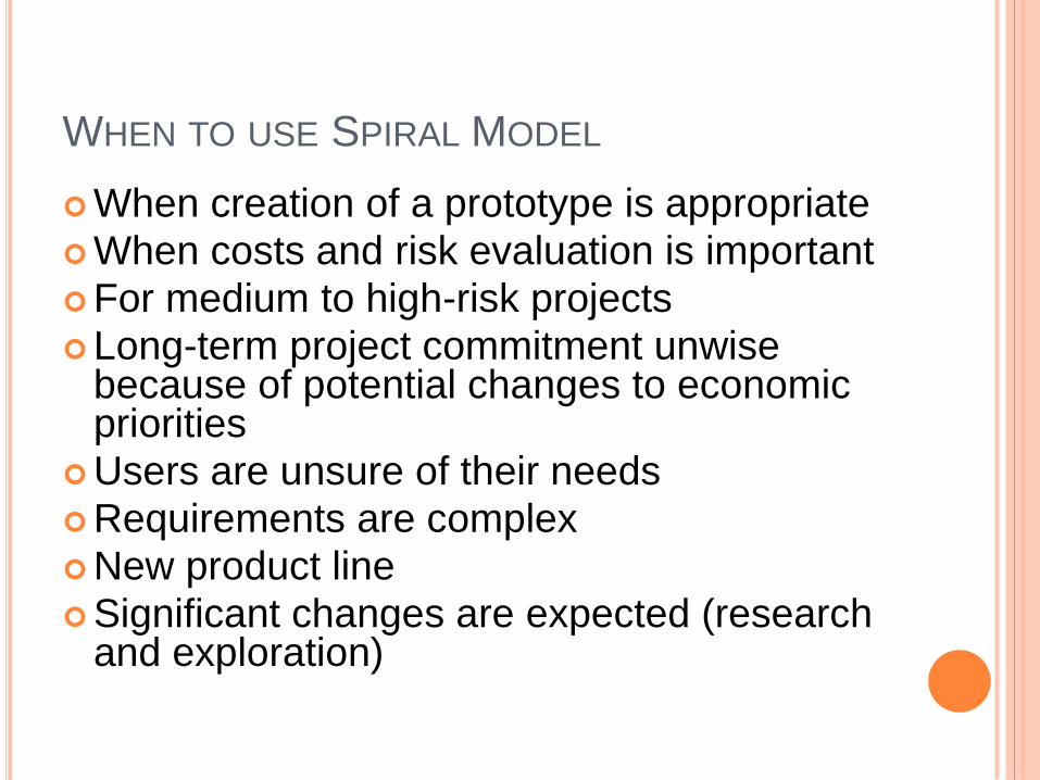
WHEN TO USE SPIRAL MODEL
When creation of a prototype is appropriate
When costs and risk evaluation is important
For medium to high-risk projects
Long-term project commitment unwise because of potential changes to economic priorities
Users are unsure of their needs
Requirements are complex
New product line
Significant changes are expected (research and exploration)

AGILE SDLC’S
Speed up or bypass one or more life cycle phases
Usually less formal and reduced scope
Used for time-critical applications
Used in organizations that employ disciplined
methods

SOME AGILE METHODS
Adaptive Software Development (ASD)
Feature Driven Development (FDD)
Crystal Clear
Dynamic Software Development Method (DSDM)
Rapid Application Development (RAD)
Scrum
Extreme Programming (XP)
Rational Unify Process (RUP)

EXTREME PROGRAMMING - XP
For small-to-medium-sized teams developing software with vague or rapidly changing requirements
Coding is the key activity throughout a software project
Communication among teammates is done with code
Life cycle and behavior of complex objects defined in test cases – again in code

XP PRACTICES (1-6) 1. Planning game – determine scope of the next release
by combining business priorities and technical estimates
2. Small releases – put a simple system into production, then release new versions in very short cycle
3. Metaphor – all development is guided by a simple shared story of how the whole system works
4. Simple design – system is designed as simply as possible (extra complexity removed as soon as found)
5. Testing – programmers continuously write unit tests; customers write tests for features
6. Refactoring – programmers continuously restructure the system without changing its behavior to remove duplication and simplify

XP PRACTICES (7 – 12)
7. Pair-programming -- all production code is written with two programmers at one machine
8. Collective ownership – anyone can change any code anywhere in the system at any time.
9. Continuous integration – integrate and build the system many times a day – every time a task is completed.
10. 40-hour week – work no more than 40 hours a week as a rule
11. On-site customer – a user is on the team and available full-time to answer questions
12. Coding standards – programmers write all code in accordance with rules emphasizing communication through the code

XP IS “EXTREME” BECAUSE Commonsense practices taken to extreme levels
If code reviews are good, review code all the time (pair
programming)
If testing is good, everybody will test all the time
If simplicity is good, keep the system in the simplest design that supports its current functionality. (simplest thing that works)
If design is good, everybody will design daily (refactoring)
If architecture is important, everybody will work at defining and refining the architecture (metaphor)
If integration testing is important, build and integrate test several times a day (continuous integration)
If short iterations are good, make iterations really, really short (hours rather than weeks)

XP REFERENCES
Online references to XP at
http://www.extremeprogramming.org/
http://c2.com/cgi/wiki?ExtremeProgrammingRoadm
ap
http://www.xprogramming.com/

FEATURE DRIVEN DESIGN (FDD)
Five FDD process activities
1. Develop an overall model – Produce class and sequence diagrams from chief architect meeting with domain experts and developers.
2. Build a features list – Identify all the features that support requirements. The features are functionally decomposed into Business Activities steps within Subject Areas.
Features are functions that can be developed in two weeks and expressed in client terms with the template: <action> <result> <object>
i.e. Calculate the total of a sale
3. Plan by feature -- the development staff plans the development sequence of features
4. Design by feature -- the team produces sequence diagrams for the selected features
5. Build by feature – the team writes and tests the code
http://www.nebulon.com/articles/index.html

DYNAMIC SYSTEMS DEVELOPMENT
METHOD (DSDM)
Applies a framework for RAD and short time frames
Paradigm is the 80/20 rule
– majority of the requirements can be delivered in a
relatively short amount of time.

DSDM PRINCIPLES
1. Active user involvement imperative (Ambassador users)
2. DSDM teams empowered to make decisions
3. Focus on frequent product delivery
4. Product acceptance is fitness for business purpose
5. Iterative and incremental development - to converge on a solution
6. Requirements initially agreed at a high level
7. All changes made during development are reversible
8. Testing is integrated throughout the life cycle
9. Collaborative and co-operative approach among all stakeholders essential

DSDM LIFECYCLE
Feasibility study
Business study – prioritized requirements
Functional model iteration
risk analysis
Time-box plan
Design and build iteration
Implementation

ADAPTIVE SDLC
Combines RAD with software engineering best
practices
Project initiation
Adaptive cycle planning
Concurrent component engineering
Quality review
Final QA and release

ADAPTIVE STEPS
1. Project initialization – determine intent of project
2. Determine the project time-box (estimation duration of the project)
3. Determine the optimal number of cycles and the time-box for each
4. Write an objective statement for each cycle
5. Assign primary components to each cycle
6. Develop a project task list
7. Review the success of a cycle
8. Plan the next cycle

TAILORED SDLC MODELS
Any one model does not fit all projects
If there is nothing that fits a particular project, pick a model that comes close and modify it for your needs.
Project should consider risk but complete spiral too much – start with spiral & pare it done
Project delivered in increments but there are serious reliability issues – combine incremental model with the V-shaped model
Each team must pick or customize a SDLC model to fit its project

AGILE WEB REFERENCES
DePaul web site has links to many Agile references
http://se.cs.depaul.edu/ise/agile.htm

QUALITY – THE DEGREE TO WHICH THE
SOFTWARE SATISFIES STATED AND IMPLIED
REQUIREMENTS
Absence of system crashes
Correspondence between the software and the users’
expectations
Performance to specified requirements
Quality must be controlled because it lowers production
speed, increases maintenance costs and can adversely
affect business

QUALITY ASSURANCE PLAN
The plan for quality assurance activities should be in writing
Decide if a separate group should perform the quality assurance activities
Some elements that should be considered by the plan are: defect tracking, unit testing, source-code tracking, technical reviews, integration testing and system testing.

QUALITY ASSURANCE PLAN
Defect tracing – keeps track of each defect found, its source, when it was detected, when it was resolved, how it was resolved, etc
Unit testing – each individual module is tested
Source code tracing – step through source code line by line
Technical reviews – completed work is reviewed by peers
Integration testing -- exercise new code in combination with code that already has been integrated
System testing – execution of the software for the purpose of finding defects.