Embed Size (px)
Citation preview
Lecture 4
Software Architectures
Roadmap of the course
3.2.20102
What is software architecture? Designing Software Architecture Requirements: quality attributes or qualities How to achieve requirements : tactics How do tactics lead to architectural styles Case studies on architectural styles, observe the achieved qualities Today: how to build an architecture with ADD method
First exercise set is available on the web Return answers in 2 weeks
Architecture in the life cycle
3
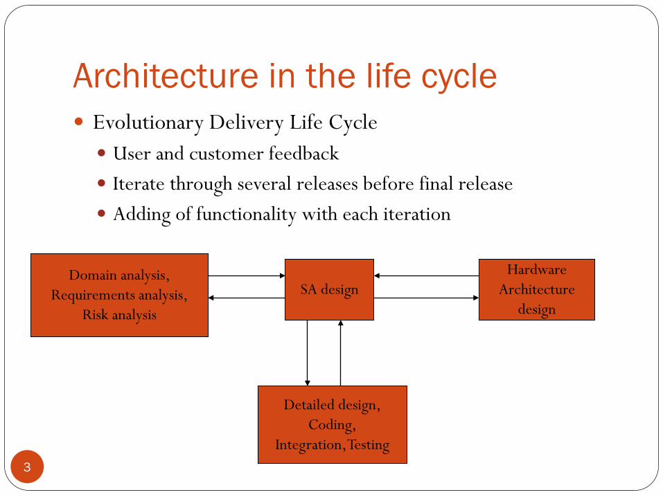
Evolutionary Delivery Life Cycle User and customer feedback Iterate through several releases before final release Adding of functionality with each iteration
Domain analysis,Requirements analysis,
Risk analysis
SA designHardware
Architecturedesign
Detailed design,Coding,
Integration, Testing
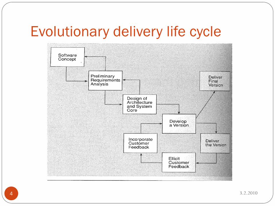
Evolutionary delivery life cycle
3.2.20104
Requirements
3.2.20105
Architecture is shaped by requirements Functional, quality, and business requirements Called architectural drivers
Identifying drivers Determine highest priority business goals (few!) Turn these business goals into quality scenarios Choose the ones with most impact on architecture: these are
the architectural drivers (less than 10)
Attribute-Driven Design (ADD)method
3.2.20106
Method to design architecture so that both functional and quality requirements are met
Defines SA by decomposing based on the quality attributes Recursive decomposition process; at each stage Tactics and architectural patterns are chosen to satisfy some
qualities Functionality is added to instantiate the module types provided
by the pattern Input: the set of quality scenarios for drivers Key drivers may change during design, due to Better understanding or changing of requirements
ADD output
3.2.20107
First several levels of a module decomposition view of an architecture
Not all details of the views result from applying ADD Necessarily coarse grained
System described as a set of containers for functionality the interactions among the containers
Critical for achieving desired qualities Provides framework for achieving the functionality Difference between ADD output and an architecture ready for
implementation Detailed design decisions postponed Flexibility
Case study
3.2.20108
Garage door opener Responsible for raising and lowering the garage door, via Switch Remote control Home information system
It is possible to diagnose problems of opener from the home information system (HIF)
Product line architecture! (PLA)
Sample input
3.2.20109
ADD assumes functional requirements and constraints as input
ADD also needs the quality requirements Set of system-specific quality scenarios These provide a checklist to be used for the development of
system-specific scenarios Only the necessary detail
Case study: quality scenarios
3.2.201010
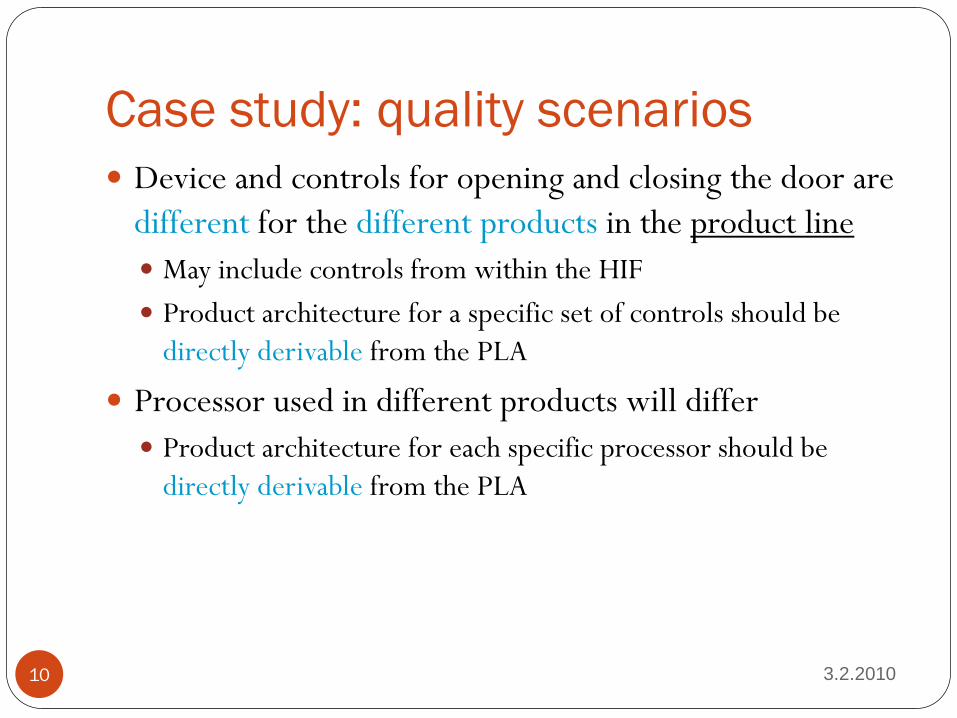
Device and controls for opening and closing the door are different for the different products in the product line May include controls from within the HIF Product architecture for a specific set of controls should be
directly derivable from the PLA
Processor used in different products will differ Product architecture for each specific processor should be
directly derivable from the PLA
Case study: quality scenarios 2
3.2.201011
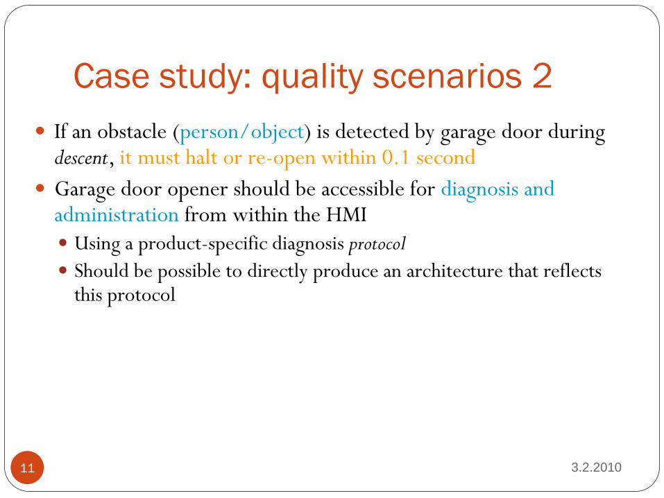
If an obstacle (person/object) is detected by garage door during descent, it must halt or re-open within 0.1 second
Garage door opener should be accessible for diagnosis and administration from within the HMI Using a product-specific diagnosis protocol Should be possible to directly produce an architecture that reflects
this protocol
ADD Steps
3.2.201012
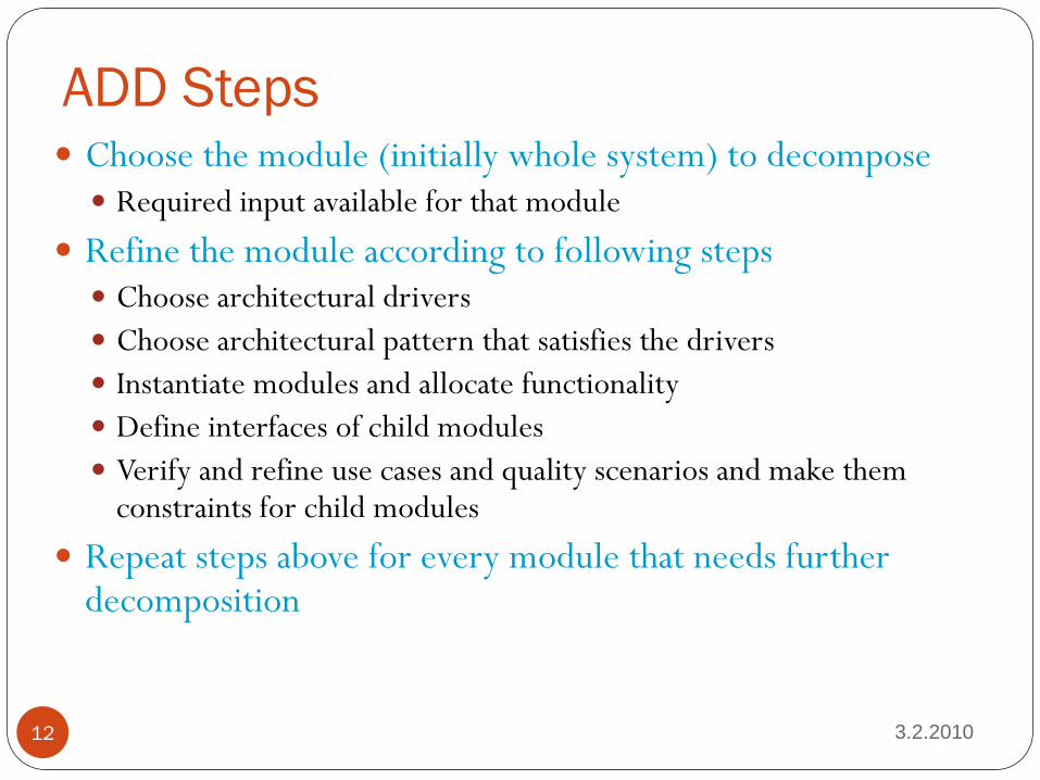
Choose the module (initially whole system) to decompose Required input available for that module
Refine the module according to following steps Choose architectural drivers Choose architectural pattern that satisfies the drivers Instantiate modules and allocate functionality Define interfaces of child modules Verify and refine use cases and quality scenarios and make them
constraints for child modules
Repeat steps above for every module that needs further decomposition
Choose module to decompose
3.2.201013
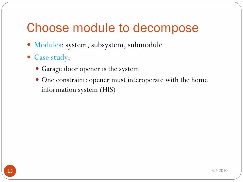
Modules: system, subsystem, submodule Case study: Garage door opener is the system One constraint: opener must interoperate with the home
information system (HIS)
Choose architectural drivers
3.2.201014
Architectural drivers: functional and quality requirements that shape the architecture Among the top priority requirements for the module To be addressed in the initial decomposition of the system
Case study: Real-time performance Modifiability to support product lines Online diagnosis supported
More on architectural drivers
3.2.201015
Determining these drivers is not only in the beginning of the process Exp: we need to see an example of a garage door to know we
want it stopped in 0.1 sec
Less important requirements are satisfied within the constraints of the most important We decompose based on drivers
Choose architectural pattern/style
3.2.201016
For each quality attribute there are Identifiable tactics and styles to implement them Each tactic is designed to realize one/more attributes The styles in which the tactics are embedded have impact on
other attributes Balance between qualities needed
We need to identify child modules required to implement the tactics
Choose architectural pattern/style 2
3.2.201017
Goal of this step Establish overall style consisting of module types Style should satisfy drivers Constructed by composing selected tactics Selection guided by Drivers Side effects of pattern on other qualities
Choose architectural pattern/style:case study 1
3.2.201018
Modifiability at design time “localize changes” tactic: semantic coherence and information
hiding Separate responsibilities dealing with user interface, communication,
sensors, diagnosis First 3 virtual machines: they will vary for the different products to be
derived from the PLA
Choose architectural pattern/style:case study 2
3.2.201019
Performance “resource demand” and “resource arbitration” tactics: increase
computational efficiency and choose scheduling policy Performance-critical computations made efficient Performance-critical computations scheduled to achieve the timing
deadline
Instantiate modules and allocate functionality
3.2.201020
Allocate functionality Use case for parent module => understand distribution of
functionality Add/remove child modules to fulfill required functionality Every use case of parent module: representable by a sequence of
responsibilities within child modules Discover necessary info exchange Information and producer/consumer roles
Instantiate modules and allocate functionality 2
3.2.201021
Represent architecture with views Dynamic and deployment info required to analyze achievement
of qualities We need additional views Module decomposition view Concurrency view Deployment view
Concurrency view
3.2.201022
Models dynamic aspects Parallel activities Synchronization
Identifies Resource contention problems Possible deadlock situations Data consistency issues
Leads to discovery new responsibilities in the modules and possibly new modules Recorded in module decomposition view Exp new module: resource manager
Concurrency view 2
3.2.201023
Component-and-connector view Components: instances of modules Connectors: carriers of virtual threads Virtual thread: execution path through system or parts of it Virtual versus operating system threads Synchronizes with, starts, cancels, communicates with
Concurrency view 3
3.2.201024
Shows instances of modules in module decomposition view for understanding mapping between views
Synchronization point located in a certain module This responsibility assigned at right place
Crossing of two virtual threads: sign that some synchronization needed
Concurrency view 4
3.2.201025
Use cases Two users doing similar things at the same time One user performing multiple activities simultaneously Starting up the system Shutting down the system
Concurrency view 5
3.2.201026
Concurrency might also be a point of variation Sequential initialization for some products, parallel for others In this case the decomposition should support techniques to
vary the initialization method Exchanging component
Deployment view
3.2.201027
New responsibilities from need to deploy On multiple processors or specialized hardware
Deployment view decomposes virtual threads Virtual threads on distinct processors Messages between them
Basis for analyzing network traffic, see possible congestion
Deployment view 2
3.2.201028
Decide if multiple instances of some modules are needed Reliability
Supports reasoning about using special-purpose hardware Architecture drivers help determining the allocation of
components to hardware Replication vs real-time scheduling
Define interfaces of child modules
3.2.201029
Module interface Services and properties provided and required Different from signatures Documents what others can use and on what they can depend
Module decomposition view documents Producers/consumers on information Patterns of interaction requiring modules to provide and use
services
Define interfaces of child modules 2
3.2.201030
Concurrency view documents Interactions among threads, leading to module interface
providing or using a service The info that a component is active Own thread running
The info that a component synchronizes, sequentializes, blocks calls
Define interfaces of child modules 3
3.2.201031
Deployment view documents Hardware requirements (special purpose HW) Timing requirements Exp: computation speed of processor
Communication requirements Exp: information updates not more than once per second
Verify and refine
3.2.201032
Decomposition into modules needs to be verified Child modules need preparation for their own decomposition Done for Functional requirements Constraints Quality requirements
Functional requirements
3.2.201033
Child modules have responsibilities Derived from functional requirements decomposition Use cases for the module Split and refine parent use cases traceability
Exp: use cases that initializes the whole system Broken into initialization of subsystems
Case study
3.2.201034
Initial responsibilities Open/close door on request Locally or remotely
Stop door within 0.1 sec when detect obstacle Interact with HIS Support remote diagnostics
Case study 2
3.2.201035
Decomposition of responsibilities User interface: recognize user requests and translate them into
form expected by the raising/lowering door module Raising/lowering door module: control actuators to raise/lower door Stop door when fully closed or fully open
Obstacle detection
Case study 3
3.2.201036
Decomposition of responsibilities, more: Communication VM Manage communication with HIS
Sensor/actuator VM Manage interaction with sensors and actuators
Scheduler Guarantee deadline
Diagnosis Manage interaction with HIS for diagnosis
Constraints
3.2.201037
Constraints of parent module satisfied by Decomposition satisfies the constraints Using certain OS
Constraint satisfied by single child module Special protocol
Constraint satisfied by multiple child modules Web usage requires two modules (client and server)
Case study
3.2.201038
Constraint: communication with HIS is maintained Communication virtual machine will recognize if this is
unavailable Constraint satisfied by a single child
Quality scenarios
3.2.201039
Need to be refined and assigned to child modules Possibilities QS completely satisfied by decomposition QS may be satisfied by decomposition with constraints on child
modules Layers and modifiability
Decomposition neutral wrt QS QS assigned to child modules
QS not satisfiable by decomposition Decomposition reconsidered or reason for this recorded Typical trade-offs
Case study
3.2.201040
Device and controls for opening and closing the door are different for the different products in the product line May include controls from within the HIF QS delegated to user interface module
Processor used in different products will differ Product architecture for each specific processor should be
directly derivable from the PLA QS delegated to all modules
Case study 2
3.2.201041
If an obstacle (person/object) is detected by garage door during descent, it must halt or re-open within 0.1 second QS delegated to scheduler and obstacle detection module
Garage door opener should be accessible for diagnosis and administration from within the HMI Using a product-specific diagnosis protocol QS split between diagnosis and communication modules
Step outcome
3.2.201042
Decomposition of module into children Each child has Set of responsibilities Set of use cases Interface Quality scenarios Collection of constraints
Enough for next iteration of decomposition
Iteration progress
3.2.201043
Vocabulary of modules and their responsibilities Variety of use cases and quality scenarios and understood
some of their ramifications Information needs of modules Their interactions
Not decided yet Communication language, algorithm for obstacle detection, etc
Iteration outcome
3.2.201044
We defined enough to allocate work teams and give them charges If we design a large system
We can proceed to next iteration and decide on answers for the questions If we design small system
Forming the team structure
3.2.201045
When modules fairly stable They can be allocated to development teams (existing, new) Team structure mirror module decomposition structure
Each team creates its own internal work practices (or adopts a system-wide set) Bulletin boards Web pages Naming conventions for files Configuration control system
Quality assurance and testing procedures set up for each group Coordinate with others
Team communication
3.2.201046
Intra team High bandwidth
Inter team Low bandwidth
Assumes system designed based on separation of concerns As software systems, the teams should strive for loose
coupling and high cohesion
Modules as mini-domains
3.2.201047
Modules encapsulate changeable details They exhibit only the interface Interface – common, unified set of services to the users Domain – specialized knowledge or expertise
Examples Module – user interface layer of systems UI tools independent of UI communication with other modules
Module – process scheduler Process number and algorithms: hidden
Most effective Assign team members according to their expertise
Organization Architecture
3.2.201048
The expertise determines the architecture Database specialist Telecom specialist
Creating a skeletal system
3.2.201049
Provide underlying capability for implementing functionality In order advantageous for project
Classical software engineering: stubbing out Architecture-driven: sequence becomes clear First Implement the SW dealing with execution and interaction of arch comps
Scheduler, rule engine, process synchronization, CS coordination Or install
Then: simplest functionality in each component Then order decreasingly according to importance to project Evolutionary Delivery Life Cycle (EDLC)
Microsoft and EDLC
3.2.201050
Complete skeletal system is early formed Low-fidelity ”working” system Rebuilt frequently (nightly) => features can be judged if enough or not
Possible problem First development team to complete portion of system defines interfaces Penalty for more complex parts of the systems Alleviation: negotiate interfaces in skeletal system early
Flight simulation example
3.2.201051
Most sophisticated SW Highly distributed Rigurous time requirements Modifiability needed Also integrability The ease with which separately developed elements can be made to work
together under SW requirements Tactics
Keeping interfaces simple, small, stable Adhering to defined protocols Loose coupling, minimal dependencies Components
Architecture business cycle
3.2.201052
Some history of the simulator
3.2.201053
Very large (1.5 million LOC) Long lifetimes (~40 years) Stringent real-time and fidelity requirements Simulator should behave EXACTLY like the real aircraft Normal flight Emergency maneuvers Equipment failures
1987: Air Force investigates OO techniques Existing simulators since 1960s, problems Integration phase was increasing exponentially with size and complexity Cost of modifications >cost of original system
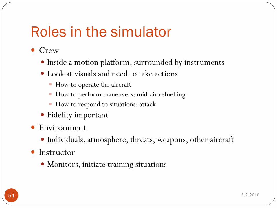
Roles in the simulator
3.2.201054
Crew Inside a motion platform, surrounded by instruments Look at visuals and need to take actions How to operate the aircraft How to perform maneuvers: mid-air refuelling How to respond to situations: attack
Fidelity important Environment Individuals, atmosphere, threats, weapons, other aircraft
Instructor Monitors, initiate training situations
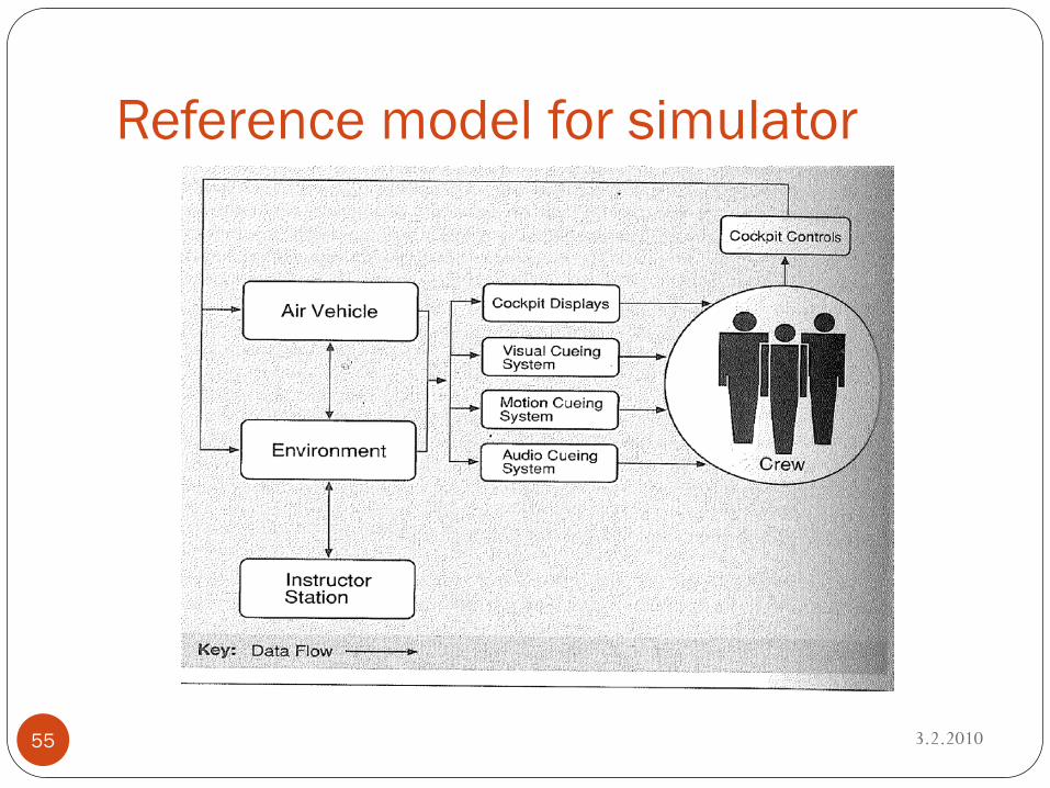
Reference model for simulator
3.2.201055
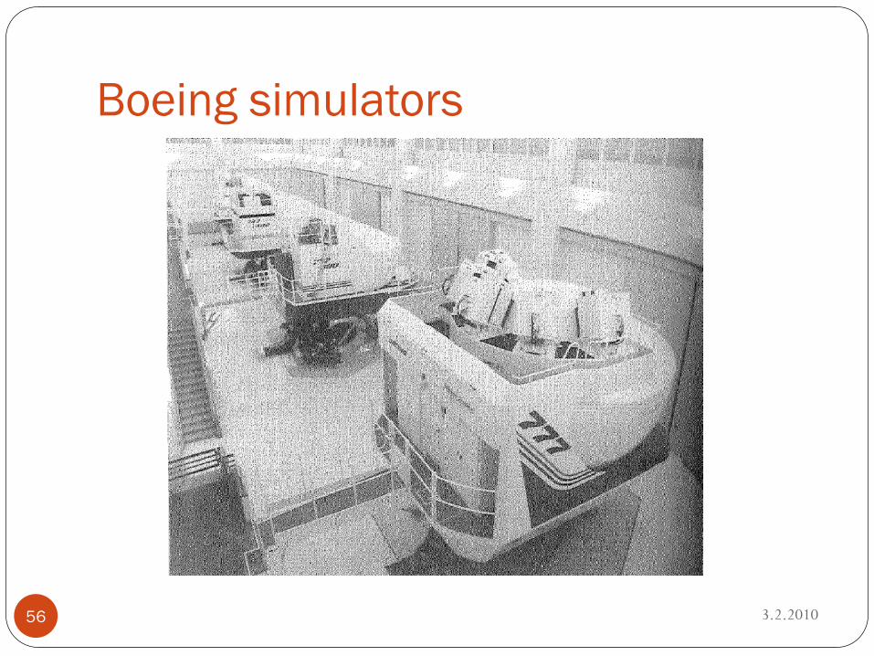
Boeing simulators
3.2.201056
Fidelity of models
3.2.201057
Exp: air pressure Model considers just the aircraft altitude Model considers the aircraft altitude and local weather Model considers the aircraft altitude, local weather, nearby
aircraft
The more fidelity, the more computational complexity
States of flight simulator
3.2.201058
Operate Configure Halt Replay
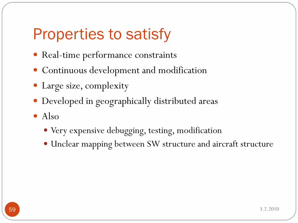
Properties to satisfy
3.2.201059
Real-time performance constraints Continuous development and modification Large size, complexity Developed in geographically distributed areas Also Very expensive debugging, testing, modification Unclear mapping between SW structure and aircraft structure
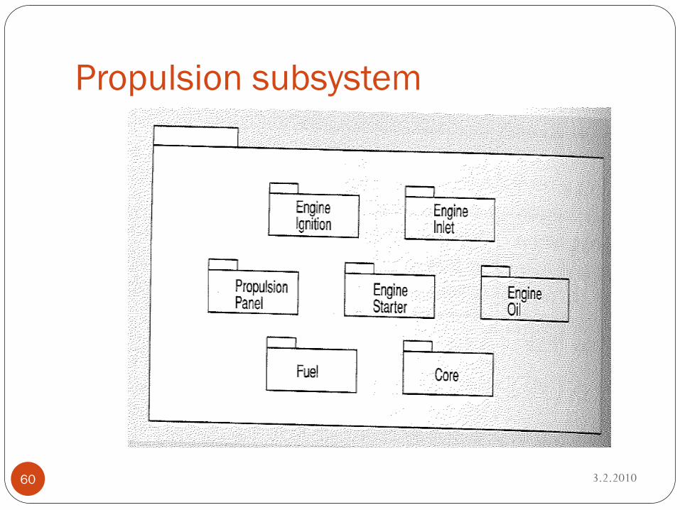
Propulsion subsystem
3.2.201060
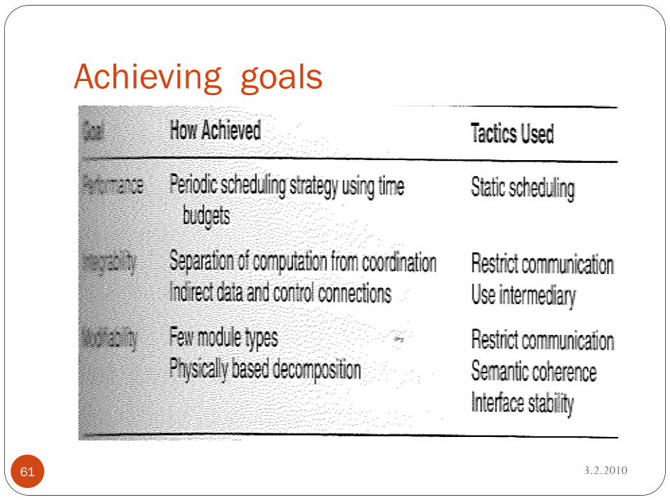
Achieving goals
3.2.201061
In a nutshell
3.2.201062
ADD aims to create a skeleton system Working interactions Give a priority to implementing modules Assign teams to modules
Main idea Incrementtal developing, testing
Flight simulator Via architectural techniques they uncovered a different module
decomposition Performance with time budgets