Embed Size (px)
Citation preview


Software Evolution

Tom Mens · Serge DemeyerEditors
Software Evolution
123

Tom MensUniversité de Mons-HainautInstitut d’InformatiqueAvenue du champ de Mars 67000 [email protected]
Serge DemeyerUniversiteit AntwerpenDept. Mathematics and Computer ScienceMiddelheimlaan 12020 [email protected]
ISBN 978-3-540-76439-7 e-ISBN 978-3-540-76440-3
DOI 10.1007/978-3-540-76440-3
ACM Computing Classification (1998): D.2.7, D.2.9, K.6.3
Library of Congress Control Number: 2007938804
© Springer-Verlag Berlin Heidelberg 2008
This work is subject to copyright. All rights are reserved, whether the whole or part of the material isconcerned, specifically the rights of translation, reprinting, reuse of illustrations, recitation, broadcasting,reproduction on microfilm or in any other way, and storage in data banks. Duplication of this publicationor parts thereof is permitted only under the provisions of the German Copyright Law of September 9,1965, in its current version, and permission for use must always be obtained from Springer. Violations areliable for prosecution under the German Copyright Law.
The use of general descriptive names, registered names, trademarks, etc. in this publication does not imply,even in the absence of a specific statement, that such names are exempt from the relevant protective lawsand regulations and therefore free for general use.
Typesetting and Production: LE-TEX Jelonek, Schmidt & Vöckler GbR, Leipzig, GermanyCover Design: KünkelLopka, Heidelberg
Printed on acid-free paper
9 8 7 6 5 4 3 2 1
springer.com

To Inge, Sara and Paulien,for being there – Tom Mens
To Ann, Sara, Niels and Jens,for illustrating the value of life – Serge Demeyer

Foreword
by Mehdi Jazayeri
Faculty of Informatics, University of Lugano, SwitzerlandDistributed Systems Group, Technical University of Vienna
The phenomenon of software evolution was observed back in the 1970s when thefirst large software systems were being developed, and it attracted renewed attentionin the 1990s. Software evolution is now a common phrase and an accepted researcharea in software engineering. There are conferences and workshops devoted to thetopic, and evolution papers appear frequently in the traditional software engineeringconferences and journals. The 2004 ACM/IEEE Software Engineering CurriculumGuidelines list software evolution as one of ten key areas of software engineeringeducation. And there are several research groups and international networks workingon software evolution. As perhaps may be expected, there are diverging researchefforts in sub-areas of software evolution, spanning theoretical studies, empiricalstudies, tools, visualization, and so on.
Since the classic and insightful work of Lehman and Belady [320], “softwareevolution” has been accepted as a phenomenon worth studying and one that we ac-knowledge poses serious problems to software projects. The problems are complexbecause they involve many dimensions, affecting, among others, all phases of thesoftware process, managerial and economic aspects, and programming languagesand environments. Further, as software engineering advances and new technologies(e.g., Web applications) and processes (e.g., open source) are introduced, softwareevolution faces different problems and challenges. At the same time, some new ad-vances (e.g. agile and model-driven processes) enable novel solutions to softwareevolution.
Evolution in general parlance implies that something has changed for the bet-ter. The Merriam-Webster Dictionary defines evolution as “a process of continuouschange from a lower, simpler, or worse to a higher, more complex, or better state,”which captures our intuitive notion of something improving. With software, evolu-tion is multi-faceted because certainly according to some metric the software getsbetter, for example it acquires a new feature or its performance improves or it isported to a new platform. Unfortunately, most improvements come with some dete-rioration in some other dimension, for example, size of software or its performanceor its structure.

VIII M. Jazayeri
In biology, the traditional area of evolution, evolution deals with species. Is theresomething analogous to “species” when we talk about software? The answer is defi-nitely yes. The species are the high-level models that we use to describe (aspects of)software. An architectural description, in fact, describes a whole species of softwaresystems. The family architecture (or product line) approach to software developmentmakes this explicit by capturing a whole family (species) of systems in terms of theircommonalities and differences. If evolution does take place in software, we can hopethat it occurs at these meta-levels, where new architectures are created as improve-ments to previous architectures, leading to evolved species. Individual elements inthe family certainly change over time but this change is hardly evolutionary in thesense that it leads to long-term improvement. What we do know about software andeven Lehman’s laws of evolution is that any individual software system will eventu-ally reach an old age when it is no longer cost-effective to modify it and it is betterto retire it. But even when we retire a software product, the associated knowledgeabout that product, captured in higher level models such as requirements and specifi-cations lives on and influences the evolution of the species. Thus, understanding andcapturing the way software evolves offers a fascinating and rich area of study.
With this wide range of issues involved in software evolution, where would a re-searcher new to the field turn to for an introduction and comprehensive overview ofthe state of the art? This book attempts to be that source. For example, this bookis a good starting point for a PhD student looking for a research topic. It can alsoform the basis for a seminar course on software evolution. The book covers mostareas of software evolution and many current problems and representative researchapproaches. I recommend the book to any researcher interested in software evolution.
The book, however, has value beyond the world of research. Because of the keyrole that evolution plays in software engineering, knowledge of the problems, ap-proaches and solutions in software evolution is useful to anyone involved in softwareengineering. Thus, if you are a software engineer, or software engineering researcher,interested or just curious about what happens to software once it is developed, or howto develop software that is evolvable, this book offers you plenty of insights.
September 2007 Mehdi Jazayeri

Preface
In October 2002, on a cold wintery Monday in Antwerp, we kicked off the RELEASEnetwork, a research network aiming to establish “Research Links to Explore and Ad-vance Software Evolution”. This research network (funded by the European ScienceFoundation) was an attempt to intensify the collaboration between a number of Euro-pean research groups active in the field of software evolution. At that time, softwareevolution was steadily becoming a subject of serious academic study, because moreand more researchers started to recognise that building software that lasts is one ofthe key challenges for our society in general and for the software engineering com-munity in particular. The RELEASE network succeeded in fostering a communityof European researchers who continue to meet on a regular basis, despite ceasing offunding in 2005. The book you are holding right now is one of the products of thiscontinued activity and we sincerely hope that it will inspire you to become part ofthe active software evolution community as well.
What Is this Book About?
This book is a collection of chapters written and peer reviewed by renowned expertsin the field of software evolution. The book does not cover all research topics in soft-ware evolution—given the wealth of information in this field that would be an im-possible task. Instead, we focus on novel trends in software evolution research and itsrelation with other emerging disciplines such as model-driven software engineering,service-oriented software development, aspect-oriented software development. Also,we do not restrict ourselves to the evolution of source code only, but address evolu-tion of other equally important software artefacts such as databases and databaseschemas, design models, software architectures, and so on. As such, this book pro-vides a representative selection of the research topics under study in this field. Evenbetter, it also demonstrates the diverse ways on how to conduct research in this field,so you will see various examples of tools, case studies (mainly open-source sys-tems), empirical validation and formal models. All contributing authors did their

X Preface
very best to provide a broad overview of the related work, contribute to a compre-hensive glossary and a list of acronyms used within the community, and—last butnot least—collect a list of books, journals, web-sites, standards and conferences thattogether represent the community. So reading this book should give you a head startwhen diving into the field of software evolution.
As such, we hope that this book will become a key reference in the field, provid-ing a basis for the next generation of software evolution researchers.
Who Should Read this Book?
This book is of interest to everyone working in the field of software engineeringand wishing to acquire more knowledge on the state-of-the-art in software evolu-tion, software maintenance and re-engineering. In particular, we target this book toresearchers, teachers, students and practitioners that need up-to-date information onthis very important research field.
So, whether you are a PhD researcher exploring a research topic, a student writ-ing a master’s thesis, a teacher in need of an overview, a practitioner looking for thestate-of-the-art, or if you are simply curious about what the field of software evolu-tion has to offer, this should be the book for you.
Why this Book?
Software has become omnipresent and indispensable in our information-based soci-ety. Almost all devices, machines and artefacts surrounding us incorporate softwareto some extent. The numerous organisations, businesses and enterprises we face ona daily basis could not function without software. As such, software is vital to oursociety and consequently we—the software engineering community—should takeup our responsibility to produce reliable software. For a long, long time, reliablesoftware was seen as software “without bugs”. As a result, most of the softwareengineering research effort has concentrated on preventing, detecting and repairingmistakes in various stages of software development. However, more and more, re-liable software has come to mean “easy to adapt”. Indeed today’s global society,with its extreme complexity and diversity imposes constant pressure to change . . . toadapt. Hence all the software that surrounds us is forced to keep pace or is bound tobe replaced by something else . . . something new.
Software evolution is the subdomain of the software engineering discipline thatinvestigates ways to adapt software to the ever-changing user requirements and op-erating environment (i.e., it addresses the How? question). However, software evo-lution also studies the change process itself, analysing remnants of the software (forinstance in version repositories) to extract trends, make predictions or understand thevery nature of the software evolution phenomenon itself (i.e., it explores the Whatand Why? questions). With the recent interest in agile software development, findinggood answers for the How? question is necessary. On the other hand, the emergence

Preface XI
of open-source software development with its sheer unlimited access to a wealth ofdata has provided an extra opportunity to address the What and Why? questions ina scientific way. Consequently, research in software evolution has seen a recent boost,and this book provides an up-to-date view on the ideas emerging from our researchlabs.
Acknowledgements
We would like to thank all persons that have contributed to this book, either directlyor indirectly. There are many people that we are indebted to:
• The contributors of the chapters of this book;• The Springer staff (in particular, Ralf Gerstner and Ulrike Stricker);• Mehdi Jazayeri, who was so kind to write a very nice foreword for this book;• David Notkin, Michael Godfrey, Václav Rajlich and Anne Keller, who spent
their precious time to review this book in its entirety, and provided numeroussuggestions for improvement;
• Joris Van Geet, Pieter Van Gorp, Filip Van Rysselberghe, Bart Van Rompaey,Bart Du Bois, Matthias Rieger and Hans Schippers, who provided valuable feed-back on several chapters of this book;
• Last but not least, we would like to thank you, reader of this book.
Many of the results that are published in this book have been achieved in the con-text of research projects or research collaborations. In particular we would like tomention:
• The Scientific Network “Research Links to Explore and Advance Software Evo-lution” (RELEASE), financed by the European Science Foundation (ESF) fromJuly 2002 to December 2005.
• The ongoing ERCIM Working Group on Software Evolution, a network of re-search institutes from all over the world working on the topic of software evolu-tion, supported by the European Research Consortium on Informatics and Math-ematics (ERCIM) since December 2004.
• The Interuniversity Attraction Poles Programme (IUAP) on “Modelling, Verifi-cation and Evolution of Software” (MOVES), financed by the Belgian State -Belgian Science Policy from January 2007 to December 2011.
• The Belgian FRFC project “Research Centre on Structural Software Improve-ment”, financed by the Fondation Nationale de Recherche Scientifique (FNRS -Belgium) from January 2005 to December 2008.
• The Swiss joint research project “Controlling Software Evolution” (COSE), fi-nanced by the Swiss National Science Foundation from July 2005 to September2007
• The Swiss joint research project “Multi-dimensional Navigation Spaces for Soft-ware Evolution” (EvoSpaces), financed by the Hasler Foundation from January2006 to December 2007.

XII Preface
• The German “Bauhaus” Project on Software Architecture, Software Reengineer-ing, and Program Understanding (see www.bauhaus-stuttgart.de)
• The European Leg2Net project: “From Legacy Systems to Services in the Net”,supported by Marie Curie Fellowships for the Transfer of Knowledge - IndustryAcademia Partnership (MTK1-CT-2004-003169).
• The European SENSORIA project: “Software Engineering for Service-OrientedOverlay Computers”, supported by the Information Society Technologies pro-gramme - Future Emerging Technologies (IST-2005-16004).
• The Dutch “Reconstructor” project sponsored by the NWO Jacquard programme,project number 638.001.408.
We hope you enjoy reading, and we welcome any comments you may have on thecontents, structure or quality of this book.
Mons and Antwerp, Tom MensSeptember 2007 Serge Demeyer

Contents
ForewordMehdi Jazayeri . . . . . . . . . . . . . . . . . . . . . . . . . . . . . . . . . . . . . . . . . . . . . . . . . . . VII
1 Introduction and Roadmap:History and Challenges of Software EvolutionTom Mens . . . . . . . . . . . . . . . . . . . . . . . . . . . . . . . . . . . . . . . . . . . . . . . . . . . . . . . 1
Part I Understanding and Analysing Software Evolution
2 Identifying and Removing Software ClonesRainer Koschke . . . . . . . . . . . . . . . . . . . . . . . . . . . . . . . . . . . . . . . . . . . . . . . . . . . 15
3 Analysing Software Repositories to Understand Software EvolutionMarco D’Ambros, Harald C. Gall, Michele Lanza, Martin Pinzger . . . . . . . . . . 37
4 Predicting Bugs from HistoryThomas Zimmermann, Nachiappan Nagappan, Andreas Zeller . . . . . . . . . . . . . 69
Part II Reengineering of Legacy Systems
5 Object-Oriented ReengineeringSerge Demeyer . . . . . . . . . . . . . . . . . . . . . . . . . . . . . . . . . . . . . . . . . . . . . . . . . . . 91
6 Migration of Legacy Information SystemsJean-Luc Hainaut, Anthony Cleve, Jean Henrard, Jean-Marc Hick . . . . . . . . . . 105
7 Architectural Transformations:From Legacy to Three-Tier and ServicesReiko Heckel, Rui Correia, Carlos Matos, Mohammad El-Ramly,Georgios Koutsoukos, Luís Andrade . . . . . . . . . . . . . . . . . . . . . . . . . . . . . . . . . . . 139

XIV Contents
Part III Novel Trends in Software Evolution
8 On the Interplay Between Software Testing and Evolutionand its Effect on Program ComprehensionLeon Moonen, Arie van Deursen, Andy Zaidman, Magiel Bruntink . . . . . . . . . . 173
9 Evolution Issues in Aspect-Oriented ProgrammingKim Mens, Tom Tourwé . . . . . . . . . . . . . . . . . . . . . . . . . . . . . . . . . . . . . . . . . . . . . 203
10 Software Architecture EvolutionOlivier Barais, Anne Françoise Le Meur, Laurence Duchien, Julia Lawall . . . . . 233
11 Empirical Studies of Open Source EvolutionJuan Fernandez-Ramil, Angela Lozano, Michel Wermelinger,Andrea Capiluppi . . . . . . . . . . . . . . . . . . . . . . . . . . . . . . . . . . . . . . . . . . . . . . . . . 263
Appendices
Resources . . . . . . . . . . . . . . . . . . . . . . . . . . . . . . . . . . . . . . . . . . . . . . . . . . . . . . . . . 291
Glossary of Terms . . . . . . . . . . . . . . . . . . . . . . . . . . . . . . . . . . . . . . . . . . . . . . . . . . 295
List of Acronyms . . . . . . . . . . . . . . . . . . . . . . . . . . . . . . . . . . . . . . . . . . . . . . . . . . . 307
References . . . . . . . . . . . . . . . . . . . . . . . . . . . . . . . . . . . . . . . . . . . . . . . . . . . . . . . . . 309
Index . . . . . . . . . . . . . . . . . . . . . . . . . . . . . . . . . . . . . . . . . . . . . . . . . . . . . . . . . . . . . 341

List of Contributors
Luis AndradeATX SoftwareRua Saraiva de Carvalho 207C1350-300 [email protected]
Olivier BaraisUniversité de Rennes 1IRIA/INRIA Triskell projectCampus de Beaulieu35042 Rennes Cé[email protected]
Magiel BruntinkCWIP.O. Box 940791090 GB, Amsterdam
andSoftware Engineering Research GroupTechnische Universiteit DelftMekelweg 4, 2628 CD, DelftThe [email protected]
Andrea CapiluppiDepartment of Computingand InformaticsFaculty of TechnologyUniversity of LincolnBrayford Pool, Lincoln LN6 7TSUnited [email protected]
Anthony ClevePReCISE Research CentreLaboratory of Database EngineeringUniversity of NamurRue Grandgagnage 21, 5000 [email protected]
Rui CorreiaDepartment of Computer ScienceUniversity of LeicesterUniversity Road LE1 7RHLeicesterUnited Kingdom
andATX SoftwareRua Saraiva de Carvalho 207C1350-300 [email protected]

XVI List of Contributors
Marco D’AmbrosFaculty of InformaticsUniversity of LuganoVia G. Buffi 13, 6904 [email protected]
Serge DemeyerLab on Re-Engineering (LORE)Department of Mathematicsand Computer ScienceUniversiteit AntwerpenMiddelheimlaan 1, 2020 [email protected]
Laurence DuchienUniversité de Lille 1LIFL/INRIA ADAM projectCité Scientifique59655 Villeneuve d’Ascq [email protected]
Mohammad El-RamlyComputer Science DepartmentCairo [email protected]
Juan Fernandez-RamilComputing Departmentand Centre for Research in ComputingThe Open UniversityWalton Hall, Milton Keynes MK7 6AAUnited [email protected]
Harald GallSoftware Engineering GroupUniversität ZürichBinzmühlestrasse 148050 Zü[email protected]
Jean-Luc HainautPReCISE Research CentreLaboratory of Database EngineeringUniversity of NamurRue Grandgagnage 21, 5000 [email protected]
Reiko HeckelDepartment of Computer ScienceUniversity of LeicesterUniversity Road LE1 7RH, LeicesterUnited [email protected]
Jean HenrardREVER s.a.Boulevard Tirou 130, 6000 [email protected]
Jean-Marc HickREVER s.a.Boulevard Tirou 130, 6000 [email protected]
Rainer KoschkeFachbereich 03Universität BremenPostfach 33 04 40, 28334 [email protected]
Georgios KoutsoukosDepartment of Computer ScienceUniversity of LeicesterUniversity Road LE1 7RH, LeicesterUnited [email protected]
Michele LanzaFaculty of InformaticsUniversity of LuganoVia G. Buffi 13, 6904 [email protected]

List of Contributors XVII
Julia LawallDIKUUniversity of Copenhagen2100 [email protected]
Anne Françoise Le MeurUniversité de Lille 1LIFL/INRIA ADAM projectCité Scientifique59655 Villeneuve d’Ascq [email protected]
Angela LozanoComputing Departmentand Centre for Research in ComputingThe Open UniversityWalton Hall, Milton Keynes MK7 6AAUnited [email protected]
Carlos MatosDepartment of Computer ScienceUniversity of LeicesterUniversity Road LE1 7RH, LeicesterUnited Kingdom
andATX SoftwareRua Saraiva de Carvalho 207C1350-300 [email protected]
Kim MensDépartement d’Ingénierie InformatiqueUniversité catholique de LouvainPlace Sainte Barbe 21348 [email protected]
Tom MensInstitut d’InformatiqueUniversité de Mons-HainautAv. du Champ de Mars 6, 7000 [email protected]
Leon MoonenSoftware Engineering Research GroupTechnische Universiteit DelftMekelweg 4, 2628 CD, DelftThe [email protected]
Nachiappan NagappanMicrosoft ResearchRedmond, [email protected]
Martin PinzgerDepartment of InformaticsUniversität ZürichWinterthurerstrasse 190, 8057 Zü[email protected]
Tom TourwéDepartment of Software Engineeringand TechnologyEindhoven University of TechnologyP.O. Box 513, 5600 MB EindhovenThe [email protected]
Arie van DeursenSoftware Engineering Research GroupTechnische Universiteit DelftMekelweg 4, 2628 CD, Delft
andCWIP.O. Box 94079, 1090 GB, AmsterdamThe [email protected]

XVIII List of Contributors
Michel WermelingerComputing Departmentand Centre for Research in ComputingThe Open UniversityWalton Hall, Milton Keynes MK7 6AAUnited [email protected]
Andreas ZellerDept. of InformaticsSaarland UniversityPostfach 15 11 50, 66041 Saarbrü[email protected]
Andy ZaidmanSoftware Engineering Research GroupTechnische Universiteit DelftMekelweg 4, 2628 CD, DelftThe [email protected]
Thomas ZimmermannDepartment of Computer ScienceUniversity of Calgary2500 University Drive NW CalgaryAlberta, T2N 1N4 [email protected]

1
Introduction and Roadmap:History and Challenges of Software Evolution
Tom Mens
University of Mons-Hainaut, Belgium
Summary. The ability to evolve software rapidly and reliably is a major challenge for soft-ware engineering. In this introductory chapter we start with a historic overview of the researchdomain of software evolution. Next, we briefly introduce the important research themes insoftware evolution, and identify research challenges for the years to come. Finally, we providea roadmap of the topics treated in this book, and explain how the various chapters are related.
1.1 The History of Software Evolution
In early 1967, there was an awareness of the rapidly increasing importance and im-pact of software systems in many activities of society. In addition, as a result ofthe many problems faced in software manufacturing, there was a general belief thatavailable techniques should become less ad hoc, and instead based on theoreticalfoundations and practical disciplines that are established in traditional branches ofengineering. These became the main driving factors for organising the first confer-ence on Software Engineering in 1968 [391]. The goal of this conference, organisedby the NATO Science Committee, was “the establishment and use of sound engineer-ing principles in order to obtain reliable, efficient and economically viable software”.Among the many activities of software engineering, maintenance was considered asa post-production activity, i.e., after the delivery and deployment of the softwareproduct.
This view was shared by Royce, who proposed in 1970 the well-known waterfalllife-cycle process for software development [446]. In this process model, that wasinspired by established engineering principles, the maintenance phase is the finalphase of the life-cycle of a software system, after its deployment. Only bug fixes andminor adjustments to the software are supposed to take place during that phase. Thisclassical view on software engineering has long governed the industrial practice insoftware development and is still in use today by several companies. It even becamea part of the IEEE 1219 Standard for Software Maintenance [239], which definessoftware maintenance as “the modification of a software product after delivery to
T. Mens, S. Demeyer (eds.), Software Evolution.DOI 10.1007/978-3-540-76440-3, © Springer 2008

2 T. Mens
correct faults, to improve performance or other attributes, or to adapt the product toa modified environment.”
It took a while before software engineers became aware of the inherent limita-tions of this software process model, namely the fact that the separation in phaseswas too strict and inflexible, and that it is often unrealistic to assume that the re-quirements are known before starting the software design phase. In many cases, therequirements continue to change during the entire lifetime of the software project. Inaddition, knowledge gained during the later phases may need to be fed back to theearlier phases.
Therefore, in the late seventies, a first attempt towards a more evolutionary pro-cess model was proposed by Yau with the so-called change mini-cycle [559] (seeFig. 1.1). In this process, important new activities, such as change impact analy-sis and change propagation were identified to accommodate the fact that softwarechanges are rarely isolated.
Also in the seventies, Manny Lehman started to formulate his, now famous, lawsof software evolution. The postulated laws were based on earlier work carried out byLehman to understand the change process being applied to IBM’s OS 360 operatingsystem [317, 318]. His original findings were confirmed in later studies involvingother software systems [320].
This was probably the first time that the term software evolution (or programevolution) was deliberately used the stress the difference with the post-deploymentactivity of software maintenance. To stress this difference even more, Lehman coinedthe term E-type software to denote programs that must be evolved because they “op-erate in or address a problem or activity of the real world”. As such, changes in thereal world will affect the software and require adaptations to it.
Nevertheless, it took until the nineties until the term software evolution gainedwidespread acceptance, and the research on software evolution started to becomepopular [24, 403]. This also lead to the acceptance of so-called evolutionary pro-cesses such as Gilb’s evolutionary development [200], Boehm’s spiral model [71]and Bennett and Rajlich’s staged model [57].
The staged process model, visualised in Fig. 1.2, is interesting in that it explicitlytakes into account the inevitable problem of software aging [410]. After the initialstage of development of a first running version, the evolution stage allows for anykind of modification to the software, as long as the architectural integrity remains
Fig. 1.1. The staged process model for evolution (adapted from [559] ©[1978] IEEE)

1 Introduction and Roadmap: History and Challenges of Software Evolution 3
Fig. 1.2. The staged process model for evolution (adapted from [57] ©[2000] ACM)
preserved. If this is no longer the case, there is a loss of evolvability (also referred toas decay) and the servicing stage starts. During this stage, only small patches can beapplied to keep the software up and running. If even such small patches become toocostly to carry out, the phase-out stage starts, leading to ultimate close down of thesystem. If the system, despite of its degraded quality, is still valuable to its variousstakeholders, it is called a legacy system. In that case, it may be wise to migrate toa new system that offers the similar or extended functionality, without exhibiting thepoor quality of the legacy system. The planning to migrate to such a new systemshould be done as soon as possible, preferably during the servicing stage.
Software evolution is also a crucial ingredient of so-called agile software devel-opment [119, 351] processes, of which extreme programming (XP) [50] is probablythe most famous proponent. In brief, agile software development is a lightweightiterative and incremental (evolutionary) approach to software development that isperformed in a highly collaborative manner and explicitly accommodates the chang-ing needs of its stakeholders, even late in the development cycle, because this offersa considerable competitive advantage for the customer. In many ways, agile methodsconstitute a return to iterative and incremental development as practiced early in thehistory of software development, before the widespread use of the waterfall model[312].
Nowadays, software evolution has become a very active and well-respected fieldof research in software engineering, and the terms software evolution and softwaremaintenance are often used as synonyms. For example, the international ISO/IEC14764 standard for software maintenance [242], acknowledges the importance ofpre-delivery aspects of maintenance such as planning. Similarly, the Software Engi-neering Body of Knowledge (SWEBOK) [2] acknowledges the need for supportingmaintenance in the pre-delivery as well as the post-delivery stages, and considers thefollowing evolution-related research themes as being crucial activities in softwaremaintenance: software comprehension, reverse engineering, testing, impact analysis,cost estimation, software quality, software measurement, process models, softwareconfiguration management, and re-engineering. These activities will be discussed inmore detail in Section 1.2.
In this book, we will continue to use the term software evolution as opposed tomaintenance, because of the negative connotation of the latter term. Maintenanceseems to indicate that the software itself is deteriorating, which is not the case. It ischanges in the environment or user needs that make it necessary to adapt the soft-ware.

4 T. Mens
1.2 Research Themes in Software Evolution
In this Section we provide an overview of some of the important research themesin software evolution. The various chapters of this book will explore some of thesethemes in more depth. Of course, it is not the aim of the book to provide completeand detailed coverage of all these themes. Instead, we have tried to offer a selectionof important issues that are actively pursued by the research community. They havebeen identified, among others in the visionary articles by Bennett and Rajlich [57]and Mens et al. [371]. Therefore, in this section, we summarise some of the mostimportant challenges and future research directions in software evolution, as reportedin these articles.
1.2.1 Dimensions of Software Evolution
There are two prevalent views on software evolution, often referred to as the whatand why versus the how perspectives [322].
The what and why view focuses on software evolution as a scientific discipline. Itstudies the nature of the software evolution phenomenon, and seeks to understand itsdriving factor, its impact, and so on. This is the view that is primarily taken in [338].An important insight that has been gained in this line of research is that the evo-lution process is a multi-loop, multi-level, multi-agent feedback system that cannotbe treated in isolation. It requires interdisciplinary research involving non-technicalaspects such as human psychology, social interaction, complexity theory, organisa-tional aspects, legislation and many more.
The how view focuses on software evolution as an engineering discipline. It stud-ies the more pragmatic aspects that aid the software developer or project manager inhis day-to-day tasks. Hence, this view primarily focuses on technology, methods,tools and activities that provide the means to direct, implement and control softwareevolution.
It is the latter view that is followed throughout most of the chapters in this book.Nevertheless, it remains necessary to develop new theories and mathematical models,and to carry out empirical research to increase understanding of software evolution,and to invest in research that tries to bridge the gap between the what and the how ofsoftware evolution.
As another “dimension” of software evolution, we can consider the types ofchanges that are being performed. Based on earlier studies by Lientz and Swanson[329], the ISO/IEC standard for software maintenance [242] proposes four categoriesof maintenance:
• Perfective maintenance is any modification of a software product after deliveryto improve performance or maintainability.
• Corrective maintenance is the reactive modification of a software product per-formed after delivery to correct discovered faults.
• Adaptive maintenance is the modification of a software product performed afterdelivery to keep a computer program usable in a changed or changing environ-ment.

1 Introduction and Roadmap: History and Challenges of Software Evolution 5
• Preventive maintenance refers to software modifications performed for the pur-pose of preventing problems before they occur.
For completeness, we also mention the work of Chapin et al. [109], who furtherextended this classification, based on objective evidence of maintainers’ activitiesascertainable from observation, and including non-technical issues such as documen-tation, consulting, training and so on. A related article that is worthwhile mentioningis the work by Buckley et al. [94], in which a taxonomy of software change is pre-sented based on various dimensions that characterise or influence the mechanisms ofchange.
1.2.2 Reverse and Re-Engineering
An important theme within the research domain of software evolution is reverse en-gineering [112]. This activity is needed when trying to understand the architectureor behaviour of a large software system, while the only reliable information is thesource code. This may be the case because documentation and design documentsare unavailable, or have become inconsistent with respect to the code because theyhave not been updated. Reverse engineering aims at building higher-level, more ab-stract, software models from the source code. Program comprehension or programunderstanding are activities that try to make sense of the wealth of information thatreverse engineering produces, by building mental models of the overall software ar-chitecture, structure and behaviour. Program comprehension also includes activitiessuch as task modelling, user interface issues, and many others.
Reverse engineering can also be regarded as the initial phase in the process ofsoftware reengineering [23]. Reengineering is necessary when we are confrontedwith legacy systems. These are systems that are still valuable, but are notoriouslydifficult to maintain [149]. Following the terminology used in the staged life cyclemodel of Fig. 1.2, we consider these systems to be in the servicing stage.
The goal of reengineering is thus to come to a new software system that is moreevolvable, and possibly has more functionality, than the original software system.The reeengineering process is typically composed of three activities, as captured bythe so-called horseshoe model visualised in Fig. 1.3 [271]. First, reverse engineeringmay be necessary when the technological platform of the software system (language,tools, machines, operating system) is outdated, or when the original developers areno longer available. This activity is typically followed by a phase of software re-structuring [22] in which we try to improve crucial aspects of the system. Finally,in a forward engineering phase we build a new running system based on the new,restructured, model.
The topic of reengineering is very important and relevant to industry, and there-fore the second part of this book will be entirely devoted to it. Chapter 5 will focuson the reengineering of object-oriented software systems. Chapter 6 will address theneed for, and means to, migrate data when reengineering large information systems.Chapter 7 discusses how to reengineer legacy systems into service-oriented systems.
Another very important research topic in reengineering research is the quest fornew and better visualisation techniques that aid in a better program comprehension,

6 T. Mens
Fig. 1.3. The horseshoe processmodel for reengineering
as well as a better understanding of the evolution of software. Such visualisationtechniques are explored in Chapter 3.
1.2.3 Incremental Change Techniques
In the change mini-cycle proposed by Yau et al. [559], and visualised in Fig. 1.1,a number of important activities related to the change process become apparent.
During the planning phase, program comprehension is of course essential to un-derstand what parts of the software will be affected by a requested change. In addi-tion, the extent or impact of the change needs to be assessed by resorting to changeimpact analysis techniques [74]. By predicting all parts of the system that are likelyto be affected by a change, they give an estimation of how costly the change will be,as well as the potential risk involved in making the change. This analysis is then usedto decide whether or not it is worthwhile to carry out the change.
Because of the fact that a change may have a non-local impact, support is neededfor what is referred to as change propagation [424, 425]. It is necessary whena change to one part of a software system requires other system parts that dependon it to be changed as well. These dependent system parts can on their turn requirechanges in other system parts. In this way, a single change to one system part maylead to a propagation of changes to be made throughout the entire software system.
During the implementation phase, it may turn out that the change cannot be im-plemented directly, and that a restructuring or refactoring of the software is requiredfirst in order to accommodate the requested change. The goal is thus to improve thesoftware structure or architecture without changing the behaviour [21, 183].
During the validation and verification phase, techniques to revalidate the softwareafter having performed changes are crucial in order to ensure that the system integrityhas not been compromised. Regression testing is one of those techniques [66]. Ratherthan repeating all tests for each new software release (which would be too costly, taketoo much time, and consume too many resources), a carefully selected subset of thetests is executed to verify that the changes did not have inadvertent effects. Chapter 8

1 Introduction and Roadmap: History and Challenges of Software Evolution 7
of this book provides an excellent overview of software testing, and its interplay withsoftware evolution.
1.2.4 Managerial Issues
Managerial issues are equally crucial to software evolution. Despite this fact, it re-mains a challenge to increase awareness among executives and project managersabout the importance and inevitability of software evolution. Indeed, various studiesand surveys indicate that over 80% of the total maintenance effort is used for non-corrective actions [1, 416]. In addition, other studies indicate that software mainte-nance accounts for at least 50% of the total software production cost, and sometimeseven exceeds 90% [329, 457, 296].
According to Lehman, software evolution problems start to appear when thereare at least two management levels involved in the software production process. Thisis confirmed by Brooks [85], who calls this the large program problem. A very im-portant managerial issue has to do with the economics of software evolution [72]. Itturns out that, in many cases, the reason for evolving software is non-technical. Morespecifically, it is an economic decision, driven by marketing or other reasons.
The main challenge is therefore to develop better predictive models, based onempirical studies, for measuring and estimating the cost and effort of software main-tenance and evolution activities with a higher accuracy [261, 466, 427, 177]. Similartechniques may also be useful to measure the cost-effectiveness of regression testing[444].
Another point of attention for managers is the need for software quality assur-ance. If proper support for measuring quality is available, this can provide crucialinformation to determine whether the software quality is degrading, and to take cor-rective actions if this turns out to be the case. Numerous software metrics have beenproposed, studied and validated as measures of software quality characteristics suchas complexity, cohesion, coupling, size and many others [83, 39, 171, 231].
Besides metrics, other more heuristic approaches may be used to detect “badsmells” or other indicators of poor-quality software. For example, Chapter 2 of thisbook studies techniques to detect and remove software redundancies and code clones,which are generally considered to be an indication of poor quality. Chapter 4 analy-ses software failures stored in a bug repository to predict and improve the softwarequality over time.
1.2.5 The Software Process
An important area of research is to find the software process model that is most ap-propriate to facilitate software evolution. In Section 1.1 we already introduced a num-ber of such process models. The IEEE standard for software maintenance [239] andthe ISO/IEC standard for software maintenance [242] also propose such a mainte-nance process model.
It is important to observe that, due to the fact that the activity of software evolu-tion is a continuous feedback process [338], the chosen software process model itself

8 T. Mens
is likely to be subject to evolution. The research area of software process improve-ment aims to reduce cost, effort and time-to-market, to increase productivity andreliability, or to affect any other relevant properties. Software process improvementcan be based on theory or empirical industrial case studies [208].
As software systems become larger and more complex, and are being developedin a collaborative and distributed way, it becomes inevitable to resort to dedicatedsoftware configuration management tools. Among others, they provide automatedsupport for the change process, they allow for software versioning and merging, andthey offer procedures (verification, validation, certification) for ensuring the qualityof each software release. Even today, research in this area is continuing in order toadvance the state-of-the-art.
Another aspect of software process improvement is the exploration and introduc-tion of novel development paradigms such as agile software development [119, 351],aspect-oriented software development [247], model-driven software development[474], service-oriented architectures [393], and many more. All of these developmentparadigms claim to improve software development and to lead to higher productivity,higher quality, and more adaptable and maintainable software. Some of these claimsare investigated in Chapter 9 for aspect-oriented development.
Of particular interest is the open source movement, which has provided a novel,strongly collaborative way of developing and evolving software. The question ariseswhether this style of software development is subject to the same laws that govern theevolution of traditional software development approaches [318]. This topic is underactive study [206, 481, 461] and will be addressed in Chapter 11 of this book.
1.2.6 Model Evolution
One of the main difficulties of software evolution is that all artefacts produced andused during the entire software life-cycle are subject to changes, ranging from earlyrequirements over analysis and design documents, to source code and executablecode. This fact automatically spawns many subdisciplines in the research domain ofsoftware evolution, some of which are listed below:
Requirements evolution. The main objectives of requirements engineering are defin-ing the purpose of a software system that needs to be implemented. Require-ments evolve because requirements engineers and users cannot predict all possi-ble uses of a system, because not all needs and (often mutually conflicting) goalsof the various stakeholders can be taken into account, and because the environ-ment in which the software is deployed frequently changes as well. Because thetopic of requirements evolution is not covered in this book, we direct the readerto [571, 570, 191] for more information.
Architecture evolution. Based on an (initial) description of the software require-ments, the overall software architecture (or high-level design) and the corre-sponding (low-level) technical design of the system can be specified. These areinevitably subject to evolution as well. The topic of architectural evolution is ex-plored in detail in Chapter 10. The related problem of evolving software product

1 Introduction and Roadmap: History and Challenges of Software Evolution 9
families is not covered in this book, but we refer to [253, 252] for an in-depthtreatment of this topic.
Data evolution. In information systems and other data-intensive software systemsit is essential to have a clear and precise description of the database schema.Chapter 6 explores in detail how to evolve and migrate such schemas.
Runtime evolution. Many commercial software systems that are deployed by largecompanies need to be constantly available. Halting the software system to makechanges cannot be afforded. Therefore, techniques are needed to change thesoftware while it keeps on running. This very challenging problem is knownunder a variety of terms, including runtime evolution, runtime reconfiguration,dynamic adaptation and dynamic upgrading [297, 284].
Service-oriented architectures (SOA) provide a new paradigm in which a user-oriented approach to software is taken [162]. The software is developed in termsof which services are needed by particular users, and these users should be ableto easily add, remove or adapt services to their needs. While this approach hasmany similarities with the component-oriented approach [486], services are onlybound together at runtime, whereas components are statically (i.e., at designtime) composed together. A service-oriented approach thus promises to be in-herently more flexible than what is available today. This is crucial, especially ine-commerce applications, where rapid and frequent change is a necessity in or-der to respond to, and survive in, a highly competitive market. Chapter 7 of thisbook will be devoted to the migration towards service-oriented architectures.
Language evolution. When looking at languages (whether it be programming, mod-elling of formal specification languages), a number of research directions cometo mind. The first one is the issue of co-evolution between software and the lan-guage that is used to represent it. Both are subject to evolution, albeit at differentspeed [167]. The second challenge is to provide more and better support forevolution in the context of multi-language software systems. A third challengeis to improve the design of languages to make them more robust to evolution(e.g., traits [451]). This challenge has always been the main driver of researchin design of new computer languages. Unfortunately, every new programmingparadigm promises to improve the software development process but introducesits own maintenance problems. This was the case for object-oriented program-ming (where the inheritance hierarchy needs to be mastered and kept under con-trol when evolving software), aspect-oriented programming (where aspects needto be evolved next to the base code, see Chapter 9 for more details), component-oriented programming, and so on. In general, every new language or technologyshould always be evaluated in the light of its potential impact on the software’sability to evolve.
Interestingly, when starting to study evolution of software artefacts different fromsource code, new challenges arise that need to be dealt with, regardless of the type ofsoftware artefact under consideration. For example, we need techniques that ensurea traceability link between software artefacts at all different levels of abstraction,ranging from very high-level requirements documents to low-level source code [16].

10 T. Mens
In presence of many different types of software artefacts that co exist, we alsoneed inconsistency management and consistency maintenance techniques to controlthe overall consistency of the software system [471], as well as techniques for co-evolution and incremental synchronisation of all related software artefacts [363].
1.3 Roadmap
The remainder of the book is structured into three parts, each containing at least threechapters. All chapters provide a detailed overview of relevant research literature.
Part I of the book, called Understanding and Improving Software Evolution isabout understanding software evolution by analysing version repositories and releasehistories, and improving software evolution by removing software redundancies andfixing bugs:
• In Chapter 2, Koschke discusses and compares various state-of-the-art tech-niques that can be used to detect and remove software clones. In addition, hedescribes techniques to remove clones through refactoring and summarises stud-ies on the evolution of clones.
• In Chapter 3, D’Ambros et al. report on how information stored in version repos-itories and bug archives can be exploited to derive useful information about theevolution of software systems.
• In Chapter 4, Zimmermann et al. explore how information about software fail-ures contained in a bug database can be mined to predict software propertiesand to improve the software quality. Their results are validated on a number ofindustrial case studies.
Part II of the book, called Reengineering of Legacy Systems contains three chaptersdevoted to the topic of legacy software systems, and how one may migrate to, orreengineer these systems into a system that is no longer outdated and more easy tomaintain and adapt:
• In Chapter 5, Demeyer discusses the state-of-the-art in object-oriented softwarereengineering. In particular, he focuses on the techniques of refactoring andreengineering patterns, and shows how these techniques can be used to captureand document expert knowledge about reengineering.
• In Chapter 6, Hainaut et al. address the problem of platform migration of largebusiness applications and information systems. More specifically, they study thesubstitution of a modern data management technology for a legacy one. Theydevelop a reference framework for migration strategies, and they focus on somemigration strategies that minimize program understanding effort.
• In Chapter 7, Heckel et al. discuss an important research trend, namely the mi-gration of legacy software systems to web services and service-oriented architec-tures by introducing architectural styles. In particular, they report on experiencewith an industrial case study in the context of a European research project, rely-ing on the technique of graph transformation.

1 Introduction and Roadmap: History and Challenges of Software Evolution 11
Part III of the book, called Novel Trends in Software Evolution addresses the relationbetween software evolution and other essential areas of software engineering such assoftware testing, software architectures, aspect-oriented software development, andopen source software.
• In Chapter 8, van Deursen et al. discuss the current state of research and practiceon the interplay between software evolution and software testing. In particular,they discuss and compare approaches for regression testing, unit testing (andthe impact of refactoring on unit tests), test smells, and many more. They alsoconsider tool support for test comprehension.
• In Chapter 9, Mens and Tourwé highlight some evolution-related issues andchallenges that adopters of aspect-oriented software development approachesencounter. They discuss state-of-the-art techniques addressing the issues of as-pect mining, extraction and evolution, and point out some issues for which noadequate solutions exist yet. This chapter can serve as a guideline for adopters ofaspect technology to get a better idea of the evolution issues they may confrontsooner or later, of the risks involved, and of the state-of-the-art in the techniquescurrently available to help them in addressing these issues.
• In Chapter 10, Barais et al. provide a detailed treatment of state-of-the-art ap-proaches to evolving software architectures. In addition, they discuss in moredetail TranSAT, one particular framework for software architecture evolution.The proposed solution combines ideas from aspect-oriented software develop-ment with architectural description languages.
• In Chapter 11, Fernandez-Ramil et al. discuss state-of-the-art techniques to studycharacteristics of evolving open source systems and their processes based on em-pirical studies. Results of the application of these techniques are given, includ-ing growth patterns, productivity, complexity patterns, social networks, cloning,processes and quality in open source systems, and so on.

Part I
Understanding and Analysing Software Evolution

2
Identifying and Removing Software Clones
Rainer Koschke
Universität Bremen, Germany
Summary. Ad-hoc reuse through copy-and-paste occurs frequently in practice affecting theevolvability of software. Researchers have investigated ways to locate and remove duplicatedcode. Empirical studies have explored the root causes and effects of duplicated code and theevolution of duplicated code. This chapter summarizes the state of the art in detecting, manag-ing, and removing software redundancy. It describes consequences, pros and cons of copyingand pasting code.
2.1 Introduction
A venerable and long-standing goal and ideal in software development is to avoidduplication and redundancy. Yet, in reality code duplication is a common habit. Sev-eral authors report on 7–23% code duplication [29, 291, 303]; in one extreme caseeven 59% [156].
Duplication and redundancy can increase the size of the code, make it hard tounderstand the many code variants, and cause maintenance headaches. The goal ofavoiding redundancy has provided the impetus to investigations on software reuse,software refactoring, modularization, and parameterization. Even in the face of theethic of avoiding redundancy, in practice software frequently contains many redun-dancies and duplications. For instance the technique of “code scavenging” is fre-quently used, and works by copying and then pasting code fragments, thereby creat-ing so-called “clones” of duplicated or highly similar code. Redundancies can alsooccur in various other ways, including because of missed reuse opportunities, pur-poseful duplication because of efficiency concerns, and duplication through parallelor forked development threads.
Because redundancies frequently exist in code, methods for detecting and re-moving them from software are needed in many contexts. Over the past few decades,research on clone detection have contributed towards addressing the issue. Tech-niques for finding similar code and on removing duplication have been investigatedin several specific areas such as software reverse engineering, plagiarism in studentprograms, copyright infringement investigation, software evolution analysis, code
T. Mens, S. Demeyer (eds.), Software Evolution.DOI 10.1007/978-3-540-76440-3, © Springer 2008

16 R. Koschke
compaction (e.g., for mobile devices), and design pattern discovery and extraction.Common to all these research areas are the problems involved in understanding theredundancies and finding similar code, either within a software system, between ver-sions of a system, or between different systems.
Although this research has progressed over decades, only recently has the paceof activity in this area picked up such that significant research momentum could beestablished. This chapter summarizes the state of the art in detecting, managing, andremoving software redundancy. It describes consequences, pros and cons of copyingand pasting code.
Software clones are important aspects in software evolution. If a systems is to beevolved, its clones should be known in order to make consistent changes. Cloningis often a strategic means for evolution. For instance, copies can be made to createa playground for experimental feature evolution, where modifications are made incloned code of a mature feature reducing the risk to break stable code. Once stable,the clone can replace its original. Often, cloning is the start of a new branch of evolu-tion if the changes in the cloned code are not merged back to the main developmentbranch. Clone detection techniques play an important role in software evolution re-search where attributes of the same code entity are observed over multiple versions.Here, we need to identify for an entity in one version the corresponding entity in thenext version (known as origin analysis [568]). If refactoring (as for instance renam-ing) is applied between versions, the relation between entities of different versions isnot always obvious. And last but not least, the evolution of clones can be studied tobetter understand the nature of cloning in practice.
2.2 Software Redundancy, Code Cloning, and Code Duplication
There are different forms of redundancy in software. Software comprises both pro-grams and data. In the data base community, there is a clear notion of redundancythat has lead to various levels of normal forms. A similar theory does not yet existfor computer programs.
In computer programs, we can also have different types of redundancy. Weshould note that not every type of redundancy is harmful. For instance, programminglanguages use redundant declarations so that a compiler is able to check consistencybetween declarations and their uses. Also, at the architectural level, n-version pro-gramming is a strategy in which redundancy is purposefully and consciously used toimplement reliable systems.
Sometimes redundant is used also in the sense of superfluous in the softwareengineering literature. For instance, Xie and Engler show that superfluous (theycall them redundant) operations such as idempotent operations, assignments thatare never read, dead code, conditional branches that are never taken, and redundantNULL-checks can pinpoint potential errors [550, 551].
Redundant code is also often misleadingly called cloned code in the literature—although that implies that one piece of code is derived from the other one in theoriginal sense of this word. According to the Merriam-Webster dictionary, a clone

2 Identifying and Removing Software Clones 17
is one that appears to be a copy of an original form. It is a synonym to duplicate.Although cloning leads to redundant code, not every redundant code is a clone. Theremay be cases in which two code segments that are no copy of each other just happento be similar or even identical by accident. Also, there may be redundant code that issemantically equivalent but has a completely different implementation.
There is no agreement in the research community on the exact notion of redun-dancy and cloning. Ira Baxter’s definition of clones expresses this vagueness:
Clones are segments of code that are similar according to some definition ofsimilarity. —Ira Baxter, 2002
According to this definition, there can be different notions of similarity. They canbe based on text, lexical or syntactic structure, or semantics. They can even be similarif they follow the same pattern, that is, the same building plan. Instances of designpatterns and idioms are similar in that they follow a similar structure to implementa solution to a similar problem.
Semantic similarity relates to the observable behavior. A piece of code, A, issemantically similar to another piece of code, B, if B subsumes the functionality ofA, in other words, they have “similar” pre and post conditions.
Unfortunately, detecting such semantic similarity is undecidable in general al-though it would be worthwhile as you can often estimate the number of developersof a large software system by the number of hash table or list implementations youfind.
Another definition of cloning considers the program text: Two code fragmentsform a clone if their program text is similar. The two code fragments may or may notbe equivalent semantically. These pieces are redundant because one fragment mayneed to be adjusted if the other one is changed. If the code fragments are executablecode, their behavior is not necessarily equivalent or subsumed at the concrete level,but only at a more abstract level. For instance, two code pieces may be identical at thetextual level including all variable names that occur within but the variable names arebound to different declarations in the different contexts. Then, the execution of thecode changes different variables. Figure 2.1 shows two textually identical segmentsin the line range of 4–6 and 10–12, respectively. The semantic difference is thatthe first segment sets a global variable whereas the second one a local variable. Thecommon abstract behavior of the two code segments is to iterate over a data structureand to increase a variable in each step.
Program-text similarity is most often the result of copy&paste; that is, the pro-grammer selects a code fragment and copies it to another location. Sometimes, theseprogrammers are forced to copy because of limitations of the programming lan-guage. In other cases, they intend to reuse code. Sometimes these clones are modifiedslightly to adapt them to their new environment or purpose.
Clearly, the definition of redundancy, similarity, and cloning in software is stillan open issue. There is little consensus in this matter. A study by Walenstein et al.[532], for instance, reports on differences among different human raters for clonecandidates. In this study, clones were to be identified that ought to be removed andWalenstein et al. gave guidelines towards clones worthwhile being removed. The

18 R. Koschke
1 i n t sum = 0 ;23 void foo ( I t e r a t o r i t e r ){4 for ( i t em = f i r s t ( i t e r ) ; has_more ( i t e r ) ; i t em = n e x t ( i t e r ) ) {5 sum = sum + v a l u e ( i t em ) ;6 }7 }8 i n t ba r ( I t e r a t o r i t e r ){9 i n t sum = 0 ;
10 for ( i t em = f i r s t ( i t e r ) ; has_more ( i t e r ) ; i t em = n e x t ( i t e r ) ) {11 sum = sum + v a l u e ( i t em ) ;12 }13 }
Fig. 2.1. Example of code clones
human raters of the clones proposed by automated tools did rarely agree upon whatconstitutes a clone worth to be removed. While the sources of inter-rater differencecould be the insufficient similarity among clones or the appraisal of the need forremoval, the study still highlights that there is no clear consensus yet, even for task-specific definitions of clones.
Another small study was performed at the Dagstuhl seminar 06301 “Duplication,Redundancy, and Similarity in Software” 2007. Cory Kapser elicited judgments anddiscussions from world experts regarding what characteristics define a code clone.Less than half of the clone candidates he presented to these experts had 80% agree-ment amongst the judges. Judges appeared to differ primarily in their criteria forjudgment rather than their interpretation of the clone candidates.
2.3 Types of Clones
Program-text clones can be compared on the basis of the program text that has beencopied. We can distinguish the following types of clones accordingly:
• Type 1 is an exact copy without modifications (except for whitespace and com-ments).
• Type 2 is a syntactically identical copy; only variable, type, or function identi-fiers have been changed.
• Type 3 is a copy with further modifications; statements have been changed,added, or removed.
Baker further distinguishes so called parameterized clones [28], which are a subsetof type-2 clones. Two code fragments A and B are a parameterized clone pair if thereis a bijective mapping from A’s identifiers onto B’s identifiers that allows an identifiersubstitution in A resulting in A′ and A′ is a type-1 clone to B (and vice versa).
While type-1 and type-2 clones are precisely defined and form an equivalence re-lation, the definition of type-3 clones is inherently vague. Some researchers consider

2 Identifying and Removing Software Clones 19
Table 2.1. Classification by Balazinska et al. [33] ©[1999] IEEE
• difference in method attributes (static, private, throws, etc.)• single-token difference in function body
– further distinction into type of token:– called method– parameter type– literal– . . .
• token-sequence difference in function body– one unit (expression or statement) differs in token sequence– two units– more than two units
two consecutive type-1 or type-2 clones together forming a type-3 clone if the gapin between is below a certain threshold of lines [29, 328]. Another precise definitioncould be based on a threshold for the Levenshtein Distance, that is, the number ofdeletions, insertions, or substitutions required to transform one string into another.There is no consensus on a suitable similarity measure for type-3 clones yet.
The above simple classification is still very rough. Balazinska et al. introduceda more refined classification for function clones [33] as described in Table 2.1. Thisclassification makes sense for selecting a suitable strategy for clone removal. Forinstance, the design pattern TemplateMethod may be used to factor out differences inthe types used in different code fragments or the design pattern Strategy can be usedto factor out algorithmic differences [31, 32]. Furthermore Balazinska et al. arguethat each class is associated with a different risk in clone removal.
Kapser et al.’s classification is the most elaborated classification to date [267,265, 264] (cf. Table 2.2). The first level is a hint about the distance of clones. Anargument can be made (although there is no empirical study on this hypothesis) thatit is likely that clones between files are more problematic than within the same fileas that it is more likely to overlook the former clones when it comes to consistentchanges. The second decision distinguishes which syntactic units are copied. Thethird gives the degree of similarity and the fourth may be used to filter irrelevant orspurious clones.
2.4 The Root Causes for Code Clones
A recent ethnographic study by Kim and Notkin [277] has shed some light on whyprogrammers copy and paste code. By observing programmers in their daily practicethey identified the following reasons.
Sometimes programmers are simply forced to duplicate code because of limita-tions of the programming language being used. Analyzing these root causes in moredetail could help to improve the language design.
Furthermore, programmers often delay code restructuring until they have copiedand pasted several times. Only then, they are able to identify the variabilities of their

20 R. Koschke
Table 2.2. Classification by Kapser et al. [265, 264] ©[2003] IEEE
1. At first level, distinguish clones within the same or across differentfiles
2. then, according to type of region:• functions• declarations• macros• hybrids (in more than one of the above)• otherwise (among typedefs, variable declarations, function signa-
tures)3. then, degree of overlap or containment4. then, according to type of code sequence:
• initialization clones (first five lines)• finalization clones (last five lines)• loop clones (60% overlap of bodies)• switch and if (60% overlap of branches)• multiple conditions: several switch and if statements• partial conditions: branches of switch/if are similar
code to be factored out. Creating abstract generic solutions in advance often leadsto unnecessarily flexible and hence needlessly complicated solutions. Moreover, theexact variabilities may be difficult to foresee. Hence, programmers tend to followthe idea of extreme programming in the small by not investing too much effort inspeculative planning and anticipation.
Systems are modularized based on principles such as information hiding, mini-mizing coupling, and maximizing cohesion. In the end—at least for systems writtenin ordinary programming languages—the system is composed of a fixed set of mod-ules. Ideally, if the system needs to be changed, only a very small number of modulesmust be adjusted. Yet, there are very different change scenarios and it is not unlikelythat the chosen modularization forces a change to be repeated for many modules. Thetriggers for such changes are called cross-cutting concerns (see also Chapter 9). Forinstance, logging is typically a feature that must be implemented by most modules.Another example is parameter checking in defensive programming where every func-tion must check its parameters before it fulfills its purpose [92]. Then copy&pastedependencies reflect important underlying design decisions, namely, cross-cuttingconcerns.
Another important root cause is that programmers often reuse the copied text asa template and then customize the template in the pasted context.
Kapser et al. have investigated clones in large systems [266]. They found whatthey call patterns of cloning where cloning is consciously used as an implementationstrategy. In their case study, they found the following cloning patterns:
Forking is cloning used to bootstrap development of similar solutions, with the ex-pectation that evolution of the code will occur somewhat independently, at leastin the short term. The assumption is that the copied code takes a separate evolu-

2 Identifying and Removing Software Clones 21
tion path independent of the original. In such a case, changes in the copy may bemade that have no side effect on the original code.
Templating is used as a method to directly copy behavior of existing code but appro-priate abstraction mechanisms are unavailable. It was also identified as a maindriver for cloning in Kim and Notkin’s case study [277]. Templating is oftenfound when a reused library has a relatively fixed protocol (that is, a requiredorder of using its interface items) which manifests as laying out the control flowof the interface items as a fixed pattern. For instance, the code in Fig. 2.1 usesa fixed iteration scheme for variable iter.
Customization occurs when currently existing code does not adequately meet a newset of requirements. The existing code is cloned and tailored to solve this newproblem.
Very likely other more organizational aspects play a role, too. Time pressure, for in-stance, does not leave much time to search for the best long-term solution. Unavail-able information on the impact of code changes leads programmers to create copiesin which they make the required enhancement; such changes then are less likely to af-fect the original code negatively. Inadequate performance measures of programmers’productivity in the number of lines of code they produce neither invite programmersto avoid duplicates.
2.5 Consequences of Cloning
There are plausible arguments that code cloning increases maintenance effort.Changes must be made consistently multiple times if the code is redundant. Oftenit is not documented where code has been copied. Manual search for copied codeis infeasible for large systems and automated clone detection is not perfect whenchanges are made to the copies (see Section 2.8). Furthermore during analysis, thesame code must be read over and over again, then compared to the other code justto find out that this code has already been analyzed. Only if you make a detailedcomparison, which can be difficult if there are subtle differences in the code or itsenvironment, you can be sure that the code is indeed the same. This comparison canbe fairly expensive. If the code would have been implemented only once in a func-tion, this effort could have been avoided completely.
For these reasons, code cloning is number one on the stink parade of bad smellsby Beck and Fowler [183]. But there are also counter arguments. In Kapser andGodfrey’s study [266], code cloning is a purposeful implementation strategy whichmay make sense under certain circumstances (see Section 2.4).
Cordy makes a similar statement [128]. He argues that in the financial domain,cloning is the way in which designs are reused. Data processing programs andrecords across an organization often have very similar purposes, and, consequently,the data structures and programs to carry out these tasks are therefore very similar.Cloning becomes then a standard practice when authoring a new program. Oppo-nents would argue that a better means would be to pursue systematic and organizedreuse through software product lines.

22 R. Koschke
Cordy also argues that the attempt to avoid cloning may lead to higher risks.Making changes to central data structures bears the risk to break existing applica-tions and requires to run expensive regression tests. Instead programmers tend tocopy the data structure if they want to restructure or add a different view and makethe necessary changes in the copy. Even the argument that errors must be fixed inevery copy does not count, he states. Errors would not necessarily be fixed in theoriginal data structure because the many running applications may already rely onthese errors, Cordy argues. On the other hand, repeated work, need for data migra-tion, and risk of inconsistency of data are the price that needs to be paid followingthis strategy. The Y2K problem has shown how expensive and difficult it is to rem-edy systems that have suffered from massive decentralized use of data structures andalgorithms.
While it is difficult to find arguments for type-1 and type-2 clones, one can moreeasily argue in favor of type-3 clones. It is not clear when you have type-3 cloneswhether the unifying solution would be easier to maintain than several copies withsmall changes. Generic solutions can become overly complicated. Maintainabilitycan only be defined in a certain context with controlled parameters. That is, a lesssophisticated programmer may be better off maintaining copied code than a highlyparameterized piece of code. Moreover, there is a risk associated with removing codeclones [128]. The removal requires deep semantic analyses and it is difficult to makeany guarantees that the removal does not introduce errors. There may be even orga-nizational reasons to copy code. Code cloning could, for instance, be used to disen-tangle development units [128].
The current debate lacks empirical studies on the costs and benefits of codecloning. There are very few empirical studies that explore the interrelationship ofcode cloning and maintainability. All of them focus on code cloning and errors asone (out of many) maintainability aspect.
Monden et al. [374] analyzed a large system consisting of about 2,000 moduleswritten in 1 MLOC lines of Cobol code over a period of 20 years. They used a token-based clone detector (cf. Section 2.8.2) to find clones that were at least 30 lineslong. They searched for correlations of maximal clone length with change frequencyand number of errors. They found that most errors were reported for modules withclones of at least 200 lines. They also found many errors—although less than in thosewith longer clones—in modules with shorter clones up to 50 lines. Yet, interestinglyenough, they found the lowest error rate for modules with clones of 50 to 100 lines.Monden et al. have not further analyzed why these maintainability factors correlatein such a way with code cloning.
Chou et al. [113] investigated the hypothesis that if a function, file, or directoryhas one error, it is more likely that is has others. They found in their analysis of theLinux and OpenBSD kernels that this phenomenon can be observed most often whereprogrammer ignorance of interface or system rules combines with copy-and-paste.They explain the correlation of bugs and copy-and-paste primarily by programmerignorance, but they also note that—in addition to ignorance—the prevalence of copy-and-paste error clustering among different device drivers and versions suggests thatprogrammers believe that “working” code is correct code. They note that if the copied

2 Identifying and Removing Software Clones 23
code is incorrect, or it is placed into a context it was not intended for, the assumptionof goodness is violated.
Li et al. [328] use clone detection to find bugs when programmers copy code butrename identifiers in the pasted code inconsistently. On average, 13% of the clonesflagged as copy-and-paste bugs by their technique turned out to be real errors for thesystems Linux kernel, FreeBSD, Apache, and PostgreSQL. The false positive rate oftheir technique is 73% on average, where on average 14% of the potential problemsare still under analysis by the developers of the analyzed systems.
2.6 Clone Evolution
There are a few empirical studies on the evolution of clones, which describe someinteresting observations. Antoniol et al. propose time series derived from clones overseveral releases of a system to monitor and predict the evolution of clones [14]. Theirstudy for the data base system mSQL showed that their prediction of the averagenumber of clones per function is fairly reliable. In another case study for the Linuxkernel, they found that the scope of cloning is limited [15]. Only few clones can befound across subsystems; most clones are completely contained within a subsystem.In the subsystem arch, constituting the hardware architecture abstraction layer, newerhardware architectures tend to exhibit slightly higher clone rates. The explanation forthis phenomenon is that newer modules are often derived from existing similar ones.The relative number of clones seems to be rather stable, that is, cloning does notoccur in peaks. This last result was also reported by Godfrey and Tu who noticedthat cloning is common and steady practice in the Linux kernel [205]. However, thecloning rate does increase steadily over time. Li et al. [328] observed for the Linuxkernel in the period of 1994 to 2004 that the redundancy rate has increased fromabout 17% to about 22%. They observed a similar behavior for FreeBSD. Most ofthe growth of redundancy rate comes from a few modules, including drivers andarch in Linux and sys in FreeBSD. The percentage of copy-paste code increasesmore rapidly in those modules than in the entire software suite. They explain thisobservation by the fact that Linux supports more and more similar device driversduring this period.
Kim et al. analyzed the clone genealogy for two open-source Java systems us-ing historical data from a version control system [278]. A clone genealogy formsa tree that shows how clones derive in time over multiple versions of a programfrom common ancestors. Beyond that, the genealogy contains information about thedifferences among siblings. Their study showed that many code clones exist in thesystem for only a short time. Kim et al. conclude that extensive refactoring of suchshort-lived clones may not be worthwhile if they likely diverge from one anothervery soon. Moreover, many clones, in particular those with a long lifetime that havechanged consistently with other elements in the same group cannot easily be avoidedbecause of limitations of the programming language.
One subproblem in clone evolution research is to track clones between versions.Duala-Ekoko and Robillard use a clone region descriptor [155] to discover a clone

24 R. Koschke
of version n in version n + 1. A clone region descriptor is an approximate locationthat is independent from specifications based on lines of source code, annotations, orother similarly fragile markers. Clone region descriptors capture the syntactic blocknesting of code fragments. A block therein is characterized by its type (e.g., for orwhile), a string describing a distinguishing identifier for the block (the anchor),and a corroboration metric. The anchor of a loop, for instance, is the condition asstring. If two fragments are syntactic siblings, their nesting and anchor are not suffi-cient to distinguish them. In such cases, the corroboration metric is used. It measurescharacteristics of the block such as cyclomatic complexity and fan-out of the block.
2.7 Clone Management
Clone management aims at identifying and organizing existing clones, controllinggrowth and dispersal of clones, and avoiding clones altogether. Lague et al. [303]and Giesecke [199] distinguish three main lines of clone management:
• preventive clone management (also known as preventive control [303]) com-prises activities to avoid new clones
• compensative clone management (also known as problem mining [303]) encom-passes activities aimed at limiting the negative impact of existing clones that areto be left in the system
• corrective clone management covers activities to remove clones from a system
This section describes research in these three areas.
2.7.1 Corrective Clone Management: Clone Removal
If you do want to remove clones, there are several way to do so. There are evencommercial tools such as CloneDr1 by Semantic Designs to automatically detectand remove clones. Cloning and automatic abstraction and removal could even bea suitable implementation approach as hinted by Ira Baxter:
Cloning can be a good strategy if you have the right tools in place. Letprogrammers copy and adjust, and then let tools factor out the differenceswith appropriate mechanisms. —Ira Baxter, 2002
In simple cases, you can use functional abstraction to replace equivalent copiedcode by a function call to a newly created function that encapsulates the copied code[166, 287]. In more difficult cases, when the difference is not just in the variablenames that occur in the copied code, one may be able to replace by macros if theprogramming languages comes with a preprocessor. A preprocessor offers textualtransformations to handle more complicated replacements. If a preprocessor is avail-able, one can also use conditional compilation. As the excessive use of macros and
1 Trademark of Semantic Designs, Inc.

2 Identifying and Removing Software Clones 25
conditional compilation may introduce many new problems, the solution to the re-dundancy problem may be found at the design level. The use of design patterns isan option to avoid clones by better design [31, 32]. Yet, this approach requires muchmore human expertise and, hence, can be less automated. Last but not least, one candevelop code generators for highly repetitive code.
In all approaches, it is a challenge to cut out the right abstractions and to come upwith meaningful names of generated functions or macros. Moreover, it is usually dif-ficult to check the preconditions for these proposed transformations—be they manualor automated–in order to assure that the transformation is semantic preserving.
2.7.2 Preventive and Compensative Clone Management
Rather than removing clones after the offense, it may be better to avoid them rightfrom the beginning by integrating clone detection in the normal development process.Lague et al. identify two ways to integrate clone detection in normal development[303].
It can be used as preventive control where the code is checked continuously—forinstance, at each check-in in the version control system or even on the fly while thecode is edited—and the addition of a clone is reported for confirmation.
A complementary integration is problem mining where the code currently undermodification is searched in the rest of the system. The found segments of code canthen be checked whether the change must be repeated in this segment for consistency.
Preventive control aims at avoiding code clones when they occur first whereasproblem mining addresses circumstances in which cloning has been used for a while.
Lague et al. assessed the benefits of integrating clone detection in normal de-velopment by analyzing the three-year version history of a very large proceduraltelecommunication system [303]. In total, 89 millions of non-blank lines (includingcomments) were analyzed, for an average size of 14.83 million lines per version. Theaverage number of functions per release was 187,000.
Problem mining is assessed by the number of functions changed that have clonesthat were not changed; that is, how often a modification was missed potentially. Pre-ventive control is assessed by the number of functions added that were similar toexisting functions; that is, the code that could have been saved.
It is interesting to note, that—contrary to their expectations—they observed a lowrate of growth in the number of overall clones in the system, due to the fact that manyclones were actually removed from the system.
They conclude from their data that preventive control would help to lower thenumber of clones. Many clones disappeared only long after the day they came intoexistence. Early detection of clones could lead to taking this measure earlier.
They also found that problem mining could have provided programmers witha significant number of opportunities for correcting problems before end-user expe-rienced them. The study indicates a potential for improving the software quality andcustomer satisfaction through an effective clone management strategy.
An alternative to clone removal is to live with clones consciously. Clones canbe managed, linked, and changed simultaneously using linked editing as proposed

26 R. Koschke
by Toomim et al. [504]. Linked editing is also used by Duala-Ekoko and Robillard.Linked editing allows one to link two or more code clones persistently. The differ-ences and similarities are then analyzed, visualized, and recorded. If a change needsto be made, linked editing allows programmers to modify all linked elements si-multaneously, or particular elements individually. That is, linked editing allows theprogrammer to edit all instances of a given clone at once, as if they were a singleblock of code. It overcomes some of the problems of duplicated code, namely, ver-bosity, tedious editing, lost clones, and unobservable consistency without requiringextra work from the programmer.
2.8 Clone Detection
While there is an ongoing debate as to whether remove clones, there is a consensusabout the importance to at least detect them. Clone avoidance during normal devel-opment, as described in the previous section, as well as making sure that a changecan be made consistently in the presence of clones requires to know where the clonesare. Manual clone detection is infeasible for large systems, hence, automatic supportis necessary.
Automated software clone detection is an active field of research. This sectionsummarizes the research in this area. The techniques can be distinguished at the firstlevel in the type of information their analysis is based on and at the second level inthe used algorithm.
2.8.1 Textual Comparison
The approach by Rieger et al. compares whole lines to each other textually [156].To increase performance, lines are partitioned using a hash function for strings. Onlylines in the same partition are compared. The result is visualized as a dotplot, whereeach dot indicates a pair of cloned lines. Clones may be found as certain patternsin those dotplots visually. Consecutive lines can be summarized to larger cloned se-quences automatically as uninterrupted diagonals or displaced diagonals in the dot-plot.
Johnson [258, 259] uses the efficient string matching by Karp and Rabin [268,269] based on fingerprints, that is, a hash code characterizing a string is used in thesearch.
Marcus et al. [345] compare only certain pieces of text, namely, identifiers usinglatent semantic indexing, a technique from information retrieval. Latent semanticanalysis is a technique in natural language processing analyzing relationships be-tween a set of documents and the terms they contain by producing a set of conceptsrelated to the documents and terms. The idea here is to identify fragments in whichsimilar names occur as potential clones.
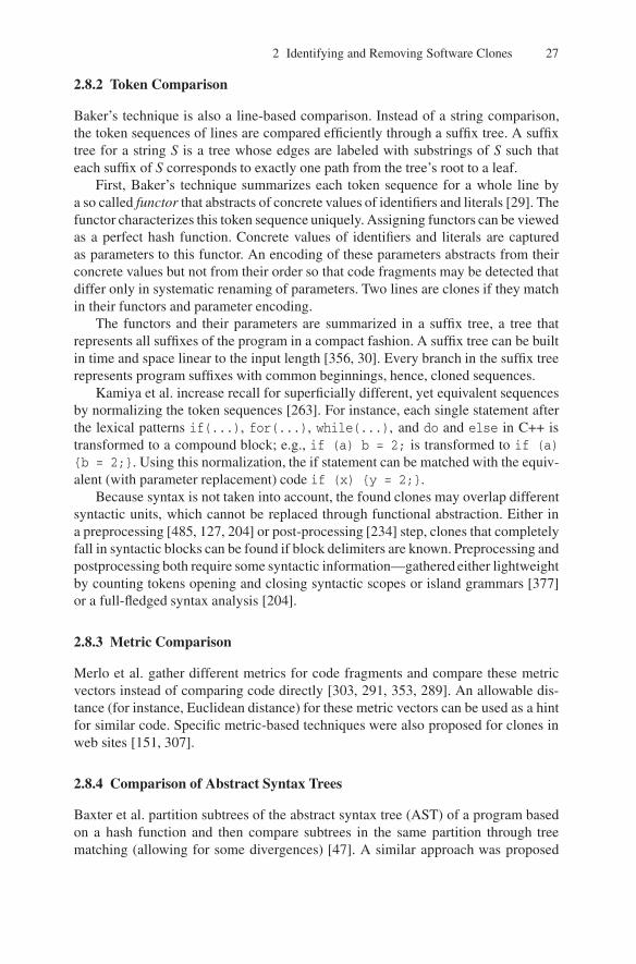
2 Identifying and Removing Software Clones 27
2.8.2 Token Comparison
Baker’s technique is also a line-based comparison. Instead of a string comparison,the token sequences of lines are compared efficiently through a suffix tree. A suffixtree for a string S is a tree whose edges are labeled with substrings of S such thateach suffix of S corresponds to exactly one path from the tree’s root to a leaf.
First, Baker’s technique summarizes each token sequence for a whole line bya so called functor that abstracts of concrete values of identifiers and literals [29]. Thefunctor characterizes this token sequence uniquely. Assigning functors can be viewedas a perfect hash function. Concrete values of identifiers and literals are capturedas parameters to this functor. An encoding of these parameters abstracts from theirconcrete values but not from their order so that code fragments may be detected thatdiffer only in systematic renaming of parameters. Two lines are clones if they matchin their functors and parameter encoding.
The functors and their parameters are summarized in a suffix tree, a tree thatrepresents all suffixes of the program in a compact fashion. A suffix tree can be builtin time and space linear to the input length [356, 30]. Every branch in the suffix treerepresents program suffixes with common beginnings, hence, cloned sequences.
Kamiya et al. increase recall for superficially different, yet equivalent sequencesby normalizing the token sequences [263]. For instance, each single statement afterthe lexical patterns if(...), for(...), while(...), and do and else in C++ istransformed to a compound block; e.g., if (a) b = 2; is transformed to if (a){b = 2;}. Using this normalization, the if statement can be matched with the equiv-alent (with parameter replacement) code if (x) {y = 2;}.
Because syntax is not taken into account, the found clones may overlap differentsyntactic units, which cannot be replaced through functional abstraction. Either ina preprocessing [485, 127, 204] or post-processing [234] step, clones that completelyfall in syntactic blocks can be found if block delimiters are known. Preprocessing andpostprocessing both require some syntactic information—gathered either lightweightby counting tokens opening and closing syntactic scopes or island grammars [377]or a full-fledged syntax analysis [204].
2.8.3 Metric Comparison
Merlo et al. gather different metrics for code fragments and compare these metricvectors instead of comparing code directly [303, 291, 353, 289]. An allowable dis-tance (for instance, Euclidean distance) for these metric vectors can be used as a hintfor similar code. Specific metric-based techniques were also proposed for clones inweb sites [151, 307].
2.8.4 Comparison of Abstract Syntax Trees
Baxter et al. partition subtrees of the abstract syntax tree (AST) of a program basedon a hash function and then compare subtrees in the same partition through treematching (allowing for some divergences) [47]. A similar approach was proposed

28 R. Koschke
earlier by Yang [557] using dynamic programming to find differences between twoversions of the same file.
Suffix trees—central to token-based techniques following Baker’s idea—can alsobe used to detect sequences of identical AST nodes. In the approach by Koschke et al.[294], the AST nodes are serialized in preorder traversal, a suffix tree is created forthese serialized AST nodes, and the resulting maximally long AST node sequencesare then cut according to their syntactic region so that only syntactically closed se-quences remain.
The idea of metrics to characterize code and to use these metrics to decide whichcode segments to compare can be adopted for ASTs as well. Jian et al. [257] char-acterize subtrees with numerical vectors in the Euclidean space ℜ and an efficientalgorithm to cluster these vectors with respect to the Euclidean distance metric. Sub-trees with vectors in one cluster are potential clones.
2.8.5 Comparison of Program Dependency Graphs
Textual as well as token-based techniques and syntax-based techniques depend uponthe textual order of the program. If the textual order is changed, the copied code willnot be found. Programmers modify the order of the statements in copied code, forinstance, to camouflage plagiarism. Or they use code cloning as in the templatingimplementation strategy (see Section 2.4), where the basic skeleton of an algorithmis reused and then certain pieces are adjusted to the new context.
Yet, the order cannot be changed arbitrarily without changing the meaning of theprogram. All control and data dependencies must be maintained. A program depen-dency graph [175] is a representation of a program that represents only the controland data dependency among statements. This way program dependency graph ab-stract from the textual order. Clones may then be identified as isomorphic subgraphsin a program dependency graph [298, 286]. Because this problem is NP hard, thealgorithms use approximative solutions.
2.8.6 Other Techniques
Leitao [324] combines syntactic and semantic techniques through a combinationof specialized comparison functions that compare various aspects (similar call sub-graphs, commutative operators, user-defined equivalences, transformations intocanonical syntactic forms). Each comparison function yields an evidence that is sum-marized in an evidence-factor model yielding a clone likelihood. Walter et al. [531]and Li et al. [327] cast the search for similar fragments as a data mining problem.Statement sequences are summarized to item sets. An adapted data mining algorithmsearches for frequent item sets.
2.9 Comparison of Clone Detection Algorithms
The abundance of clone detection techniques calls for a thorough comparison sothat we know the strength and weaknesses of these techniques in order to make an

2 Identifying and Removing Software Clones 29
informed decision if we need to select a clone detection technique for a particularpurpose.
Clone detectors can be compared in terms of recall and precision of their findingsas well as suitability for a particular purpose. There are several evaluations alongthese lines based on qualitative and quantitative data.
Bailey and Burd compared three clone and two plagiarism detectors [27]. Amongthe clone detectors were three of the techniques later evaluated by a subsequent studyby Bellon and Koschke [55], namely, the techniques by Kamiya [263], Baxter [47],and Merlo [353]. For the latter technique, Bailey used an own re-implementation;the other tools were original. The plagiarism detectors were JPlag [420] and Moss[452].
The clone candidates of the techniques were validated by Bailey, and the acceptedclone pairs formed an oracle against which the clone candidates were compared.Several metrics were proposed to measure various aspects of the found clones, suchas scope (i.e., within the same file or across file boundaries), and the findings in termsof recall and precision.
The syntax-based technique by Baxter had the highest precision (100%) and thelowest recall (9%) in this experiment. Kamiya’s technique had the highest recalland a precision comparable to the other techniques (72%). The re-implementation ofMerlo’s metric-based technique showed the least precision (63%).
Although the case study by Bailey and Burd showed interesting initial results, itwas conducted on only one relatively small system (16 KLOC). However, becausethe size was limited, Bailey was able to validate all clone candidates.
A subsequent larger study was conducted by Bellon and Koschke [54, 55]. Theirlikewise quantitative comparison of clone detectors was conducted for 4 Java and4 C systems in the range of totaling almost 850 KLOC. The participants and theirclone detectors evaluated are listed in Table 2.3.
Table 2.4 summarizes the findings of Bellon and Koschke’s study. Row clonetype lists the type of clones the respective clone detector finds (for clone types, seeSection 2.3). The next two rows qualify the tools in terms of their time and spaceconsumption. The data is reported at an ordinal scale −−, −, +, + + where −− isworst (the exact measures can be found in the paper to this study [54, 55]). Recalland precision are determined as in Bailey and Burd’s study by comparing the clone
Table 2.3. Participating scientists
Participant Tool Comparison
Brenda S. Baker [29] Dup TokenIra D. Baxter [47] CloneDr ASTToshihiro Kamiya [263] CCFinder TokenJens Krinke [298] Duplix PDGEttore Merlo [353] CLAN Function MetricsMatthias Rieger [156] Duploc Text

30 R. Koschke
Table 2.4. Results from the Bellon and Koschke study. Adapted from [54, 55] ©[2007] IEEE
Baker Baxter Kamiya Krinke Merlo Rieger
Clone type 1, 2 1, 2 1, 2, 3 3 1, 2, 3 1, 2, 3Speed + + − + −− + + ?RAM + − + + + + ?Recall + − + − − +Precision − + − − + −
detectors’ findings to a human oracle. The same ordinal scale is used to qualify theresults; exact data are reported in the paper [54, 55].
Interestingly, Merlo’s tool performed much better in this experiment than in theexperiment by Bailey and Burd. However, the difference in precision of Merlo’sapproach in this comparison to the study by Bailey and Burd can be explained bythe fact that Merlo compared not only metrics but also the tokens and their textualimages to identify type-1 and type-2 clones in the study by Bellon and Koschke.
While the Bailey/Burd and Bellon/Koschke studies focus on quantitative eval-uation of clone detectors, other authors have evaluated clone detectors for the fit-ness for a particular maintenance task. Rysselberghe and Demeyer [525] comparedtext-based [156, 438], token-based [29], and metric-based [353] clone detectors forrefactoring. They compare these techniques in terms of suitability (can a candidatebe manipulated by a refactoring tool?), relevance (is there a priority which of thematches should be refactored first?), confidence (can one solely rely on the results ofthe code cloning tool, or is manual inspection necessary?), and focus (does one haveto concentrate on a single class or is it also possible to assess an entire project?).They assess these criteria qualitatively based on the clone candidates produced bythe tools. Figure 2.2 summarizes their conclusions.
Bruntink et al. use clone detection to find cross-cutting concerns in C programswith homogeneous implementations [93]. In their case study, they used CCFinder—Kamiya’s [263] tool evaluated in other case studies, too—one of the Bauhaus2
clone detectors, namely ccdiml, which is a variation of Baxter’s technique [47], andthe PDG-based detector PDG-DUP by Komondoor [286]. The cross-cutting con-cerns they looked for were error handling, tracing, pre and post condition checking,and memory error handling. The study showed that the clone classes obtained byBauhaus’ ccdiml can provide the best match with the range checking, null-pointer
criterion most suitable technique
suitability metric-basedrelevance no differenceconfidence text-basedfocus no difference
Fig. 2.2. Assessment by Rysselberghe and Demeyer. Adapted from [525] ©[2004] IEEE
2 http://www.axivion.com.

2 Identifying and Removing Software Clones 31
checking, and error handling concerns. Null-pointer checking and error handling canbe found by CCFinder almost equally well. Tracing and memory error handling canbest be found by PDG-DUP.
2.10 Clone Presentation
Because there is typically a huge amount of clones in large systems and these clonesdiffer in various attributes (type, degree of similarity, length, etc.), presentation issuesof clone information are critical. This huge information space must be made accessi-ble to a human analyst. The analyst needs a holistic view that combines source codeviews and architectural views.
There have been several proposals for clone visualization. Scatter plots—alsoknown as dot plots—are two-dimensional charts where all software units are listedon both axes [114, 156, 512] (cf. Fig. 2.3). There is a dot if two software units aresimilar. The granularity of software units may differ. It can range from single lines tofunctions to classes and files to packages and subsystems. Visual patterns of cloningmay be observed by a human analyst. A problem with this approach is scalability formany software units and the order of the listed software units as this has an impacton the visual patterns. While there is a “natural” order for lines (i.e., lexical order)within a file, it is not clear how to order more coarse-grained units such as functions,files, and packages. Lexical order of their names is in most cases as arbitrary asrandom order.
Johnson [260] proposes Hasse diagrams for clone representation between sets offiles so that one can better see whether code has been copied between files, whichis possibly more critical than cloning within a file (cf. Fig. 2.4). A Hasse diagram(named after a German mathematician) is used to draw a partial order among sets asan acyclic graph. Directed arcs connect nodes that are related by the order relationand for which no other directed path exists.
(a) Three clones (b) Three clones, one modified line
Fig. 2.3. Dot plots [114, 156, 512]

32 R. Koschke
Fig. 2.4. Hasse diagramadapted from [260]
In Johnson’s context, each match of a block of text identifies a range of characters(or lines) from two (or more) files. For each subset of files, one can total the numberof characters that the matching process has discovered to match between the givenset of files. A subset of files forms a node, if the files have non-zero matches. Theinclusion between subsets of files yields the edges.
Rieger et al. [437] propose to use Michele Lanza’s polymetric views[309] tovisualize various aspects of clones in one view (cf. Fig. 2.5). A polymetric viewis again based on the graph metaphor and representation where a node representsa software unit and an edge a cloning relation. Visually, additional information canbe attached to the graph by the degrees of freedom for the position (X/Y in thetwo-dimensional space), color of nodes and edges, thickness of edges, breadth andwidth of nodes. Rieger et al. propose a fixed set of metric combinations to be mappedonto graphical aspects to present the clone information from different perspective fordifferent tasks.
Beyond polymetric views, Rieger et al. [437] propose a variation of tree maps toshow the degree of cloning along with the system decomposition (cf. Fig. 2.6). Treemaps display information about entities with a hierarchical relationship in a fixedspace (for instance, the whole system on one screen) where the leaves of the hierar-chy contain a metric to be visualized. Each inner node aggregates the metric valuesof its descendants. Each node is represented through a piece of the available space.The space of a descendent node is completely contained in the space of its ancestor.
Fig. 2.5. Polymetric view adapted from [437]

2 Identifying and Removing Software Clones 33
Fig. 2.6. A system decomposition whose leaves are annotated with the number of cloned linesof code and its corresponding tree map
There is no overlap in space for nodes that are not in an ancestor/descendant rela-tion. This is how the hierarchy is presented. Essentially the hierarchy is projectedonto the two dimensional space seen from the root of the hierarchy. In order to showthe hierarchy clearly, the space of each node appears as rectangle where the directionof subdivision of nested nodes is alternated horizontally and vertically at each level.The space of each rectangle is proportional to the metric.
This visualization was originally proposed by Ben Shneiderman in the early1990s to show space consumption of a hard disk with a hierarchical file system.While space is used very efficiently, problems arise when the hierarchy is deeplynested.
Another visualization was proposed by Wattenberg to highlight similar substringsin a string. The arc diagram has an arc connecting two equal substrings in a stringwhere the breadth of the arc line covers all characters of the identical substrings. Thediagram shows the overlapping of strings but becomes quickly unreadable if manyarcs exist. Another disadvantage is that it shows only pairs but not classes of equalstrings.
Tairas et al. [489] have created an Eclipse plugin to present clone information.One of their visualizations is the clone visualizer view, a window showing the dis-tribution of clone classes among files (cf. Fig. 2.8). A bar in this view representsa source file, a stripe within a bar a cloned code segment, and its colors the set ofclone classes the segment is member of.
Fig. 2.7. Arc diagram adapted from [537]

34 R. Koschke
Fig. 2.8. Clones visualizer view in Eclipse adapted from [489]
2.11 Related Fields
Clone detection has applications in other fields and—vice versa—ideas from relatedfields can be reused for clone detection.
Bruntink et al. for instance, use clone detectors to search for code that couldbe factored out as aspects using an aspect-oriented language [92, 93]. They identifyerror handling, tracing, pre and post condition checking, and memory error handling.Although they used classic clone detectors that were not designed for this particularpurpose, the clone detectors appeared to be helpful. Classic clone detectors try tofind similar code—similar in terms of their program text. The implementations ofan aspect, on the other hand, are often very heterogeneous and are similar only ata more semantic level. For instance, precondition checking tests each parameter ofa function for certain criteria. At the implementation level, functions differ in theorder and type of parameters so that checks are generally different in the programtext.
The code compaction community tries to minimize the memory footprint of pro-grams for small devices. They use very similar algorithms to identify redundant codethat could be compressed [124].
The detection of plagiarism faces similar but even worse problems as clone de-tection [452, 420, 180, 343, 251, 337, 210]. In plagiarism cases, people try to cam-ouflage their copy in order to make it more difficult to detect the plagiarism. In orderto reuse classic clone detectors for plagiarism, we would need to reduce programs toa normal form for comparison. This normalization, on the other hand, could lead tofalse positives. Also in virus detection, code patterns significant for a particular hos-tile code need to be quickly identified in large code bases, where virus programmerstry to vary the patterns.
Another application of clone detection is the comparison of versions or variantsof software systems. While versions derive from each other, variants have a commonancestor. In both cases, they are very similar. In software evolution research, whereinformation on software units is observed over time or versions, respectively, it isnecessary to map the software entities of one version to those of the other version inorder to carry over the information. This problem is called the origin analysis [508].The same problem needs to be solved when two software variants are to be compared

2 Identifying and Removing Software Clones 35
or merged [237]. Relaying solely on names of these units for this analysis may bemisleading if a refactoring like renaming has taken place [183]. Also, the refactor-ing extract method moves statements from one function to create a new function.Clone detection can help to establish a mapping between two versions or variants ofa program. Several authors have used clone detection techniques or at least a codesimilarity measure to determine this mapping [509, 568, 206, 205, 524, 552, 553].
The difference of comparing versions or variants to detecting clones is that thetask here is to map a code entity onto only one or at least a small set of candidatesin the other system, the comparison is only between systems (clones within the sameversion or variant are irrelevant), cloning is the rule rather than the exception as thetwo versions or variants overlap to a very high degree, the focus is on the differ-ences rather than the similarities, and the comparison should tolerate renaming andall refactorings that move entities around such as pull-up field, move method, etc.
2.12 Conclusions
This section summarizes the open issues of the subareas in software cloning pre-sented in this chapter.
One fundamental issue is that there is no clear consensus on what is a softwareclone. We should develop a general notion of redundancy, similarity, and cloning, andthen identify more task-oriented categorizations of clones. Other research areas havesimilar difficulties in defining their fundamental terms. For instance, the architecturecommunity debates the notion of architecture and the community of object-orientedprogramming the notion of object. To some extent, these fundamental terms definethe field. So it is important to clarify them. It is difficult, for instance, to create bench-marks to evaluate automatic clone detectors if it is unclear what we consider a clone.It were very helpful if we could establish a theory of redundancy similar to normalforms in databases.
Concerning types of clones, we should look at alternative categorizations ofclones that make sense (e.g., semantics, origins, risks, etc.). On the empirical sideof clone categorizations, we should gather the statistical distribution of clone typesin practice and investigate whether there are correlations among apparently orthogo-nal categories. Studying which strategies of removal and avoidance, risks of removal,potential damages, root causes, and other factors are associated with these categorieswould be worthwhile, too.
Although the two empirical studies by Kim and Notkin as well as Kapserand Godfrey on the root causes and main drivers for code cloning are impor-tant first contributions, this area certainly requires more similar studies. Other po-tential reasons should be investigated, such as insufficient information on globalchange impact, badly organized reuse and development processes, questionableproductivity measures (e.g., LOCs per day), time pressure, educational deficien-cies, ignorance, or shortsightedness, intellectual challenges (e.g., generics), lack ofprofessionalism/end-user programming by non experts, and organizational issues,e.g., distributed development and organizations.

36 R. Koschke
Identifying the root causes would help us to fight the reasons, not just the symp-toms, for instance, by giving feedback for programming language design.
Clearly, more empirical studies are required. These studies should take industrialsystems into account, too, as it is unclear to which extent these current observa-tions can be attributed to the nature of open-source development. It would also beinteresting to investigate what the degree of cloning tells about the organization ordevelopment process. For instance, a study by Nickell and Smith reports that the ex-treme programming projects in their organization produce significantly fewer clones[394, 533].
In particular, empirical investigations of costs and benefits of clone removal areneeded so that informed refactoring decisions can be made. We currently do not havea clear picture of the relation of clone types to quality attributes. Most of what wereport on the consequences of cloning is folklore rather than fact. We should expectthat there is a relevance ranking of clone types for removal, that is, some clonesshould be removed, others are better left in certain circumstances. Moreover, we canexpect that different types of clones are associated with different removal techniquesin turn associated with different benefits, costs, and risks.
Unwanted clones should be avoided right from the start. But it is not yet clearwhat is the best integration of clone detection in the normal development process. Inparticular, what are the benefits and costs of such possible integrations and what arereliable cloning indicators to trigger refactoring actions?
If it is too late to avoid cloning and if existing clones cannot be removed, weshould come up with methods and tools to manage these clones. This clone manage-ment must stop further spread of clones and help to make changes consistently.
The most elaborated field in software cloning is the automatic detection of clones.Yet, there is still room for improvement as identified in the quantitative and quali-tative comparisons. Most helpful would be a ranking function that allows to presentclone candidates in an order of relevance. This ranking function can be based on mea-sures such as type, frequency, and length of clones but should also take into accountthe task driving the clone detection.
Although various types of visualization to present clones have been proposedwe have not fully explored all opportunities. There is a large body of research oninformation visualization in general and software visualization in particular that wehave not yet explored for clone visualization. In order to understand which visual-ization works best for which purpose, we need more systematic empirical research.Clone representation is difficult due to the large and complex information space. Wehave various aspects that we need to master: the large amount of data, clone classmembership, overlap and inclusion of clones, commonalities and differences amongclones in the same class, degree of similarity, and other attributes such as length,type, frequency, and severity.
Clone detection overlaps with related fields, such as code compression or virusdetection. The interesting questions here are “What can clone detection learn fromother fields?” and “What can other fields learn from clone detection?”

3
Analysing Software Repositoriesto Understand Software Evolution
Marco D’Ambros1, Harald C. Gall2, Michele Lanza1, and Martin Pinzger2
1 Faculty of Informatics, University of Lugano, Switzerland2 Department of Informatics, University of Zurich, Switzerland
Summary. Software repositories such as versioning systems, defect tracking systems, andarchived communication between project personnel are used to help manage the progress ofsoftware projects. Software practitioners and researchers increasingly recognize the potentialbenefit of mining this information to support the maintenance of software systems, improvesoftware design or reuse, and empirically validate novel ideas and techniques. Research isnow proceeding to uncover ways in which mining these repositories can help to understandsoftware development, to support predictions about software development, and to plan variousevolutionary aspects of software projects.
This chapter presents several analysis and visualization techniques to understand softwareevolution by exploiting the rich sources of artifacts that are available. Based on the data modelsthat need to be developed to cover sources such as modification and bug reports we describehow to use a Release History Database for evolution analysis. For that we present approachesto analyse developer effort for particular software entities. Further we present change couplinganalyses that can reveal hidden change dependencies among software entities. Finally, weshow how to investigate architectural shortcomings over many releases and to identify trendsin the evolution. Kiviat graphs can be effectively used to visualize such analysis results.
3.1 Introduction
Software evolution analysis is concerned with software changes, their causes, andtheir effects. It uses all sources of a software system to perform a retrospective anal-ysis. Such data comprises the release history with all the source code and the changeinformation, bug report data, and data that can be extracted from the running system.In particular the analysis of release and bug reporting data has gained importance be-cause they store valuable information for analysing the evolution of software. Whilethe recovery of the data residing in versioning systems such as CVS or Subversionhas become a well explored topic, the ultimate challenge lies in the recovered dataand its interpretation.
Some recent topics addressed in the field of analysing software repositories in-clude the following:
T. Mens, S. Demeyer (eds.), Software Evolution.DOI 10.1007/978-3-540-76440-3, © Springer 2008

38 M. D’Ambros et al.
• Developer effort and social network analysis. One of the goals in this topic isto find out the effort that team members are spending on maintaining and evolv-ing software modules and how they communicate with each other. This allowsa project manager to plan resources and reason about shortcomings in develop-ment processes and the team structure.
• Change impact and propagation. The main focus of this topic is to assess the im-pact of a change, such as the addition of a new or change of an existing feature,on the architecture, design and implementation of a software system. Being ableto assess the impact of changes allows one to estimate the effort for maintenanceand evolution tasks, to determine the impact of a change on the existing archi-tecture and design of a system. Results are also used to provide guidelines forprogrammers such as if changing method a the programmer should also changemethod b and c.
• Trend and hotspot analysis. In this topic the trend of software entities is observedto find out shortcomings in the current architecture, design and implementationof software systems. Hotspots are the entities that frequently change and there-fore are critical for the evolution of a system. One of the goals is to find heuristicsand warning mechanisms that alarm project managers and architects of negativetrends of software entities (and in particular of system hotspots) and providesuggestions to return the system into a stable state.
• Fault and defect prediction. A wealth of information is provided by softwarerepositories that can be input to data mining and machine learning algorithms tocharacterize current and predict future properties of software entities. One prop-erty of software entities that is addressed by many approaches is the predictionof the location and number of defects in software entities such as source files.The result is a list of entities that will likely to be affected by defects whichallows the development team to plan preventive actions such as refactoring.
In this chapter we address the first three topics and present techniques such as ourFractal Figures to analyse development effort, the Evolution Radar to analyse thechange impact on source files, and Kiviat diagrams to analyse metric trends andto detect system hotspots. In the next section we present a general approach foranalysing software repositories to understand software evolution. Examples of howto model and retrieve the data is presented in Section 3.3. The modeled data is the in-put for the different software evolution analysis techniques we present in Section 3.4.
3.2 An Overview of Software Repository Analysis
When mining software repositories one can consider many software artifacts: Sourcecode from versioning systems, bugs from bug tracking systems, communication frome-mail lists or any further software artifacts such as documentation. This diversity ofinformation is the foundation for many kinds of evolution analyses.

3 Analysing Software Repositories to Understand Software Evolution 39
3.2.1 A General Approach
Figure 3.1a shows a sketch of how to analyse software repositories for studying soft-ware evolution. In the schema we identify three fundamental steps necessary for thefinal analysis of the data:
1. Data modeling. The first step of mining consists of creating a data model of anevolving software system. Various aspects of the system and its evolution can bemodeled: The last version of the source code, the history of files as recorded bythe versioning system, several versions of the source code (e.g., one per release),documentation, bug reports, developers mailing list archives, etc.While aspects such as source code or file histories have a direct mapping to thesystem, for others like bug reports or mailing list archives the useful informationhas to be filtered and linked to software artifacts. When designing the model itis important to consider the tradeoff between the amount of data to deal with(in the analysis phase) and the potential benefit this data can have, i.e., not allaspects of a system’s evolution have to be considered, but only the ones whichcan address a specific software evolution problem or set of problems.
2. Data retrieval and processing. Once the model is defined, a concrete instanceof it has to be created. For this, we need to retrieve and process the informationfrom the various data sources. The processing can include the parsing of thedata (e.g., source code, log files, bug report etc.), the application of matching
(a) General schema (b) Our approach
Fig. 3.1. The general approach and our customization to mining software repositories

40 M. D’Ambros et al.
techniques to link different data sources (e.g., versioning system artifacts withbug reports [179, 136]), the reconstruction of information not recorded (e.g.,reconstruct commit information from CVS log files [566]) and the applicationof other techniques such as data mining.
3. Data analysis. The analysis consists of using the modeled and retrieved data totackle a software evolution problem or set of problems by means of differenttechniques and approaches.
3.2.2 Our Approach
Figure 3.1b sketches how we approach software evolution analysis through miningsoftware repositories. As data sources we consider versioning system log files to-gether with bug report data. We define a data model describing an evolving softwaresystem based on these two data sources (data modeling). Given a system to analyse,versioning system log files and bug report data are parsed and a concrete instanceof the model is created (data retrieval). All the models are then stored in a ReleaseHistory Database (RHDB), which is the starting point for all the subsequent analy-ses. For the analysis part we use different techniques and tools, aimed at addressingspecific software evolution problems.
In the remainder of this chapter we first introduce the RHDB, the data modelbehind it and the way the database is populated. Then we present different types ofsoftware evolution analyses built on top of the RHDB: Developers effort distribu-tion, change coupling, trend analysis and hot-spot detection. For the RHDB and eachevolution analysis technique we also present related work in the field.
3.3 Release History
When we refer to the history of a software artifact, we mean the way it was devel-oped, how it grew or shrank over time, how many developers worked on it and towhich extent. These kinds of information are recorded by versioning systems andcan be reconstructed by parsing their log files. However, when we analyse evolu-tion our goal is to understand a system’s architecture, the dependencies among itscomponents and to detect evolutionary hot-spots. To support this kind of analysis,additional information such as problem bug reports can be used. The problem is tolink this data to the software artifacts to answer specific questions, e.g., which fileswere affected by a given bug?
In this section we present our approach for integrating versioning system infor-mation and bug report data and populating a RHDB [179, 136]. We first introducethe versioning system and the bug tracking system from which we retrieve the data.Then we describe the model behind the RHDB, i.e., the model of an evolving soft-ware system and we finally explain how we populate the database.
CVS and Bugzilla. CVS [135] has been the most used version control systemby the open source community over the last years. Currently it is being replaced bySubversion [480] (SVN).

3 Analysing Software Repositories to Understand Software Evolution 41
Our approach for populating the RHDB is based on the versioning system logfiles, thus it can be applied to both CVS and SVN. For each versioned file, thelog file contains the information recorded by the versioning system at commit-time:The version number (or revision), the timestamp of the commit, the author who per-formed the commit, the state (whether the file is still under development or removed),the number of lines added and removed with respect to the previous commit, thebranches having the current version as root and the comments written by the authorduring the commit. Listing 3.1 shows a chunk of a CVS log file.
RCS file: /cvsroot /mozilla /js/src/xpconnect /codelib /Attic /mozJSCodeLib .cpp ,vWorking file: codelib /mozJSCodeLib .cpphead: 1.1branch :locks : strictaccess list:symbolic names :
FORMS_20040722_XTF_MERGE: 1.1.4.1XTF_20040312_BRANCH: 1.1.0.2
keyword substitution : kvtotal revisions : 6; selected revisions : 6description :----------------------------revision 1.1date: 2004/04/19 10:53:08; author : alex.fritze %crocodile -clips.com; state: dead;branches : 1.1.2; 1.1.4;file mozJSCodeLib .cpp was initially added on branch XTF_20040312_BRANCH.----------------------------revision 1.1.4.2date: 2004/07/28 09:12:21; author : bryner %brianryner .com; state: Exp; lines: +1 -0Sync with current XTF branch work.----------------------------...----------------------------revision 1.1.2.1date: 2004/04/19 10:53:08; author : alex.fritze %crocodile -clips.com; state: Exp; lines: +430 -0Fixed bug 238324 (XTF javascript utilities ).===============================================================================================
Listing 3.1. A CVS log file chunk of mozJSCodeLib.cpp
Bugzilla [95] is a bug tracking system that is used heavily in the open sourcecommunity. Its core is a customizable database with a web interface which allowsdevelopers, testers as well as normal users to report and keep track of issues detectedin the software system.
A typical bug report contains the following pieces of information: An id whichunequivocally identifies the bug, the bug status composed of status (new, assigned,reopened, resolved, verified, closed) and resolution (fixed, invalid, wontfix, notyet,remind, duplicate, worksforme), the location in the system identified by the productand the component, the operating system and the platform on which the bug wasdetected, a short description of the problem and a list of comments about it (longdescription). Moreover, each bug refers to several people: The reporter who reportedthe bug, a person who is in charge to fix it (assigned to), quality assurance peoplewho are responsible for ensuring that the software meets certain quality standards(qa), and a list of people interested in being notified of the bug fixing progress (CC).

42 M. D’Ambros et al.
Fig. 3.2. The RHDB data model
3.3.1 The RHDB Model
Figure 3.2 shows the core of the RHDB model.In the model a CVS commit corresponds to a file version, having all the commit-
related information: Version associated to the commit, date, author, state (exp ordead), lines added and removed with respect to the previous commit, branches asso-ciated with the version and the comment written by the author. A file history, whichcorresponds to the actual file in the file system, is composed of a sequence of fileversions, one per commit. It has a filename with (rcsfile) and without (workingfile)the entire path name. A file history can be associated to many aliases, used for tag-ging system releases. A project is composed of modules which contain directoriesand file histories. A directory can contain sub-directories and file histories. Finally,a file version can be associated to one or more bug reports. The relationship betweenbug reports and file versions is “many to many”, meaning that a file version (andtherefore a file history) can be affected by many bugs and a bug can affect differentfile versions and file histories.
3.3.2 Populating the RHDB
Figure 3.3 sketches the RHDB populating process. The user needs to enter the urlof the CVS repository and of the Bugzilla database, and then the populating task(which depending on the size of the system can take several hours) is executed inbatch mode. The main steps of the process are:
1. The latest version of the system is retrieved by means of a CVS checkout com-mand. Then, for each directory, the log file describing the history of the con-tained files is retrieved and parsed.
2. For each file, the data about all its commits (its history) is stored in the databaseas well as a link to the actual file.
3. Every time a reference to a bug is found in the commit message (the commentwritten by the author at commit time), the corresponding bug report is retrieved

3 Analysing Software Repositories to Understand Software Evolution 43
Fig. 3.3. The RHDBpopulating process
from the Bugzilla database, parsed and stored in the database, together with thelink to the affected file. Since the link between CVS artifacts and Bugzilla prob-lem report is not formally defined, we use regular expressions to detect bug ref-erences.
3.3.3 Related Work
Several approaches were proposed to create and populate an underlying model of anevolving software system. These approaches vary according to which informationthey consider (e.g., only source code repository or also bug tracking system and mailarchives), which data sources they support (e.g., only CVS or also SVN, ClearCaseetc.) and how these sources are linked to each other.
The previously presented RHDB is based on the CVS versioning system and theBugzilla bug tracking system, where the links between the two sources are built aspresented in Section 3.3.2. The main contribution of the RHDB is that it was the firstto link CVS artifacts and Bugzilla problem reports.
Two other approaches similar to the RHDB, also based on CVS and Bugzilla,but which also use other sources of information are Hipikat [133, 511, 510] by D.Cubranic et al. and softChange [196, 195] by D. German. Both techniques use infor-mation from mail archives and, in addition, Hipikat also considers data from docu-mentation on the analysed project website (if available).
In both approaches the links between different information sources are inferredbased either on conventions (e.g., in some projects there is a convention to include inthe commit comment a reference to the bug tracking system entry) or heuristics (e.g.,it is likely that the author of a bug fix has committed a source code revision close tothe time that the problem report was closed in the bug tracking system).
A common problem encountered while linking mail archives with CVS reposi-tory is that people tend to have multiple e-mail addresses, which might not be thesame as the ones recorded in the CVS log files [197].
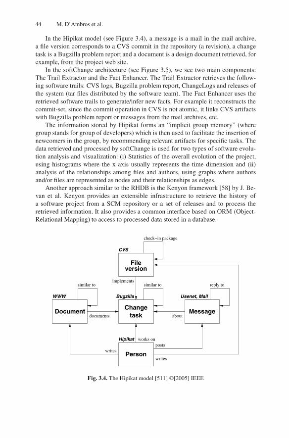
44 M. D’Ambros et al.
In the Hipikat model (see Figure 3.4), a message is a mail in the mail archive,a file version corresponds to a CVS commit in the repository (a revision), a changetask is a Bugzilla problem report and a document is a design document retrieved, forexample, from the project web site.
In the softChange architecture (see Figure 3.5), we see two main components:The Trail Extractor and the Fact Enhancer. The Trail Extractor retrieves the follow-ing software trails: CVS logs, Bugzilla problem report, ChangeLogs and releases ofthe system (tar files distributed by the software team). The Fact Enhancer uses theretrieved software trails to generate/infer new facts. For example it reconstructs thecommit-set, since the commit operation in CVS is not atomic, it links CVS artifactswith Bugzilla problem report or messages from the mail archives, etc.
The information stored by Hipikat forms an “implicit group memory” (wheregroup stands for group of developers) which is then used to facilitate the insertion ofnewcomers in the group, by recommending relevant artifacts for specific tasks. Thedata retrieved and processed by softChange is used for two types of software evolu-tion analysis and visualization: (i) Statistics of the overall evolution of the project,using histograms where the x axis usually represents the time dimension and (ii)analysis of the relationships among files and authors, using graphs where authorsand/or files are represented as nodes and their relationships as edges.
Another approach similar to the RHDB is the Kenyon framework [58] by J. Be-van et al. Kenyon provides an extensible infrastructure to retrieve the history ofa software project from a SCM repository or a set of releases and to process theretrieved information. It also provides a common interface based on ORM (Object-Relational Mapping) to access to processed data stored in a database.
Fig. 3.4. The Hipikat model [511] ©[2005] IEEE

3 Analysing Software Repositories to Understand Software Evolution 45
Fig. 3.5. The softChange process[195]
Figure 3.6 shows the high-level data flow architecture of Kenyon. The DataMan-ager class is the execution entry point: It reads a configuration file and invokes theother components, i.e., the Configuration Retrieval, the Fact Extractor and the Ob-ject Data Storage. The SCMInterface class isolates Kenyon from the concrete im-plementation of different SCM systems. The FactExtractor and MetricLoader ab-stract classes are the API points for specific tool invocation extensions. This meansthat users of Kenyon are free to attach their own external Fact Extractor and Met-ric Loader tools (typically analysis-specific). Besides this extension, Kenyon offerspredefined fact extractor and metric loader tools. Kenyon saves the results from each
Fig. 3.6. The high-level data flow architecture of Kenyon [58], ©ACM, 2005

46 M. D’Ambros et al.
processed configuration to a database. An ORM mechanism is provided to help au-tomate the storage to and retrieval of Java object from the database.
As depicted in Figure 3.6 Kenyon retrieves information from SCM only (orfilesystem, i.e., set of releases), without considering other sources, such as bug track-ing system or mail archives. On the other hand Kenyon supports several SCMs,namely: CVS, SVN, ClearCase and sets of releases in the filesystem.
A common aspect of Kenyon and the RDHB is that both store the data for laterevolution analyses, while for softChange and Hipikat the task for using the data isalready defined.
3.4 Software Evolution Analysis
The RHDB contains a concrete instance of our model of an evolving software sys-tem. This is the starting point from which, with the support of tools and techniques,we can do several types of analyses. Each technique we designed and each tool weimplemented considers a particular perspective on software evolution, and addressesa particular goal. In the following, we present some software evolution analysis prob-lems and describe our techniques to tackle them.
3.4.1 Analysing Developer Effort
The first software evolution problem we address concerns development effort. Wewant to answer questions such as: How many developers worked on an entity? Howwas the effort distributed among them? Is there an owner of the entity, based on thecode-ownership principle? Moreover, we also want to be able to categorize entitiesin terms of “effort distribution”. For an analyst or a project manager, the answersto these questions provide valuable information for a possible restructuring of thedevelopment teams.
Version control systems record the information necessary to answer these ques-tions, as each ach artifact has a list of versions corresponding to commits, and thelist of authors who performed the commits3. The problem is how to represent andaggregate this large amount of low-level information4 to get an insight into the teamstructure and to understand who are the responsible/s of a software entity, scalingfrom a module down to the individual file.
Our approach is based on the “Fractal Figure” [139, 136] visualization, whichencapsulates all the author-related information of a given software artifact. It givesan immediate view of how, in terms of development effort and distribution amongauthors, an artifact has been developed. We can easily figure out whether the de-velopment was done mainly by one author or many people contributed to it and to
3 We only know who performed the commit, i.e., if a commit includes changes done byseveral people, those are all mapped to a single developer.
4 As an example: The Mozilla system, on the first of September 2005, had 4656 source codefiles with a total number of 326,000 file versions, corresponding to hundreds of thousandsof commit-related data to analyse.

3 Analysing Software Repositories to Understand Software Evolution 47
which extent. A fractal figure is composed of a set of rectangles with different sizesand colors. Each rectangle, and thus each color, represents an author who worked onthe file. The area of the rectangle is proportional to the percentage of commits per-formed by the author over the whole set of commits. For more details on the layoutalgorithm and the expressive power of Fractal Figures see [139].
Fractal Figures allow software entities to be categorized in terms of effort dis-tribution among developers following the gestalt principle. We defined four visualpatterns representing four development models, depicted in Figure 3.7: (a) One de-veloper, (b) few balanced developers, (c) one major developer and (d) many balanceddevelopers.
Development patterns allow us to categorize entities according to the way theywere developed from an authors’ perspective. However, the visual nature of both thepatterns and the Fractal Figures themselves, is useful to get a qualitative impressiononly of the development model. To provide also a quantitative measure, we intro-duced the Fractal Value, which for a given software artifact is defined as:
Fractal Value = 1− ∑ai∈A
(nc(ai)
NC
)2
, with NC = ∑ai∈A
nc(ai) (3.1)
where A = {a1,a2, . . . ,an} is the set of authors and nc(ai) is the number of commitsperformed by the author ai with respect to the given software artifact. The FractalValue measures how fragmented a Fractal Figure is, that is how much the work spenton the corresponding entity is distributed among different developers. (3.1) is definedsuch that the smaller the quantity nc(ai)
NC is (always less than 1), the more it is reducedby the square power, since the square equation is sub-linear between 0 and 1. There-fore, the smaller a rectangle is, the less its negative contribution to the Fractal Valueis. The Fractal Value ranges from 0 to 1 (not reachable). It is 0 for entities developedby one author only, while it tends to 1 for entities developed by a large number ofauthors.
To exploit the expressive power of Fractal Figures we applied them in context ofpolymetric views [309]. Figures represent RHDB entities, namely files, directories,and modules. To apply them on a directory or a module, we sum up the commit infor-mation of all the files belonging to the given directory or module. We map a metricmeasurement of the size of the figure. The metric can be structural such as LOC
(a) One developer (b) Few balanceddevelopers
(c) One major deve-loper
(d) Many balanceddevelopers
Fig. 3.7. Development patterns based on the gestalt of Fractal Figures [139] ©[2005] IEEE

48 M. D’Ambros et al.
or evolutionary such as number of commits, number of bugs, number of lines addedetc.
In the following we present different example scenarios which show how to useFractal Figures to address the problem of understanding development effort distribu-tion.
Detecting a Major Developer
Figure 3.8 shows the webshell directory hierarchy of Mozilla. Fractal Figures rep-resent directories containing at least one file, while grey figures represent containerdirectories, i.e., directories containing only subdirectories. The size metric maps thedirectory size in terms of number of contained files. We see that the webshell hierar-chy of Mozilla includes all the four development patterns. The sub-hierarchy markedas 1 has a major developer pattern (the blue author did most of the commits). Thereverse engineer knows whom to ask questions about the design and the code con-tained in this sub-hierarchy. On the contrary, the directory marked as 2 shows thatmany developers worked on it, and there is no main developer. Modifying code inthese directories will be more effort since there is not a single person to ask questionsabout the code. The reverse engineer will need support of other tools such as Code-Crawler [310] or BugCrawler [138]. This information is not complex or hard to get,but the value of the Fractal Figure visualization is that it conveys this information ina context (the hierarchy in this case), easy and fast to read, and with the same visualprinciple for all the software entities to which it is applied.
Fig. 3.8. Fractal Figures appliedto the webshell hierarchy ofMozilla [139] ©[2005] IEEE. Thesize metric maps the directory sizein terms of number of containedfiles

3 Analysing Software Repositories to Understand Software Evolution 49
Fig. 3.9. Fractal Figures applied to the network/protocol hierarchy of Mozilla. The sizemetric maps the number of bug reports
Re-Assessing Development Team Formation
Figure 3.9 shows an example with the network protocol implementation of Mozilla.Most of the directories which introduced bugs have a many balanced developer pat-terns, but one which has a one major developer pattern: network/protocol/http/src. This directory is responsible for most of the bugs generated in the network/protocol hierarchy. Such a view can be valuable for a project manager or an an-alyst. It shows that a re-assessment of the formation of the development team isneeded, given the high number of bugs and one major developer pattern of thenetwork/protocol/http/src directory.
Related Work
Many software evolution analysis techniques focus more on the developers and theirinteraction with software artifacts than on software artifacts themselves. Liu et al[330] applied the CVSChecker tool to analyse CVS log files with the aim of un-derstanding author contributions and identifying patterns. They wanted to study theopen source development process and to understand what activities are carried out inopen source project and by whom. The CVSChecker tool supports the analysis of theperformance of an individual developer and the effort distribution patterns of teams.
CVSChecker has a set of parsers which extract information from the CVS sourcecode repository and store them in a relational database. The tool then uses this infor-mation to produce four kinds of visualizations:
1. Temporal distribution of CVS activity, for each developer (see Figure 3.10a);2. Distribution of CVS operation types, for each developer;3. Distribution of CVS operation types, for each file;4. Added and removed lines of code (LOC) by each developer, on each file (see an
example in Figure 3.10b).

50 M. D’Ambros et al.
(a) Temporal distribution of CVS activity for each developer
(b) Added and removed LOC for each developer, for each file
Fig. 3.10. CVSChecker example visualizations [330]
The visualizations are used in [330] to extract development patterns to characterizethe open source development process.
Gîrba et al. [203] defined a measurement for the notion of code ownership inCVS repositories. They defined that a developer is the owner of a file if he/she ownsthe major part of it in terms of lines. He/she owns a line of code if he/she was thelast one that committed a change to that line in the repository. Based on that princi-ple, they introduced the Ownership Map visualization, which shows the evolution ofa software project, according to the following rules (summarized in Figure 3.11):
• Each file is represented as a colored line;• The x axis represents the time dimension, from left to right;• Each commit of a file in the repository is represented as a colored circle on the
corresponding line;• Each developer is represented by a color;• Commits (circles) are colored according to the developer who did them, while
pieces of histories of files (corresponding to pieces of lines) are colored accord-ing to the owner of the file, during the considered time interval.
In [203] the authors used the Ownership Map visualization to define developmentpatterns such as monologue (a period where all the changes and most files belong tothe same author), takeover (a developer takes over a large amount of code in a shortamount of time), team work (two or more developers commit a quick succession of

3 Analysing Software Repositories to Understand Software Evolution 51
Fig. 3.11. The princi-ples of the OwnershipMap visualization [203]©[2005] IEEE
changes to multiple files) etc. The patterns were defined with the aim of characteriz-ing different developer behaviors.
In [528], Voinea and Telea presented a similar visualization, in which CVS filesare represented as colored lines and the color represents the developer. The visual-ization is implemented in CVSgrab, a tool which also supports the visualization andanalysis of activities in the repository. In [528] the authors applied a cluster algo-rithm on the visualizations to put files (lines) with similar development (with respectto either the authors or the activity) close to each other. The aim of their work was toallow developers and project managers to visually explore the evolution of a softwareproject in a way that facilitates the system and process understanding.
Voinea et al. also presented the CVSscan tool [529], based on CVSgrab for ex-tracting the data from the CVS repository. The tool can visualize the evolution ofCVS files by visualizing the evolution of individual lines. CVSscan provides threetypes of color encoding to associate the color of each code line to its author. This vi-sualization is used in [529] to understand who performed modifications on the codeand where, thus facilitating the development process understanding.
Author information stored in CVS repositories was also used in the context ofsocial networks. In [68] Bird et al. created social networks or email correspondentsfrom OSS email archives. They linked emails with CVS accounts to analyse therelationship of email activity and commit activity and the relationship of social statuswith commit activity. The case study they conducted on the Apache HTTP serverproject indicated a strong relationship between the level of activity in the source code,and a less strong relationship with document change activity. They also found outthat developers (people with email and CVS accounts) play a much more significantsocial role than other participants in the mail archives.
3.4.2 Change Coupling Analysis
Change coupling is the implicit dependency between two or more software artifactsthat have been observed to frequently change together during the evolution of a sys-tem. This co-change information can either be present in the versioning system, ormust be inferred by analysis. For example SVN marks co-changing files at committime as belonging to the same change set while in CVS the files which are change(i.e., logically) coupled must be inferred from the modification time of each individ-ual file.

52 M. D’Ambros et al.
The Evolution Radar [137, 140] is an interactive visualization technique foranalysing change couplings to detect architecture decay and coupled componentsin a given software system. It addresses the following questions: What are the com-ponents (e.g., modules) with the strongest coupling? Which low level entities (e.g.,files) are responsible for these couplings?
Figure 3.12 shows the structural principles of the Evolution Radar. It visualizesdependencies between groups of entities, in this specific case dependencies betweenmodules (groups) as group of files (entities). The module in focus is visualized asa circle and placed in the center of a pie chart. All the other system modules are rep-resented as sectors. The size of the sectors is proportional to the number of files con-tained in the corresponding module. The sectors are sorted according to this size met-ric, i.e., the smallest is placed at 0 radian and all others clockwise (see Figure 3.12).Within each sector files are represented as colored circles and positioned using polarcoordinates where the angle and the radius are computed according to the followingrules:
• Radius d (or distance from the center). It is inversely proportional to the changecoupling the file has with the module in focus, i.e., the more they are coupled,the closer the circle (representing the file) is to the center circle (representing themodule in focus).
• Angle θ. The files of each module are alphabetically sorted considering the entiredirectory path, and the circles representing them are then uniformly distributedin the sectors with respect to the angle coordinates.
Arbitrary metrics can be mapped on the color and the size of the circle figures. In theEvolution Radar files are placed according to the change coupling they have with themodule in focus. To compute this metric value we use the following formula:
CC(M, f ) = maxfi∈M
CC( fi, f ) (3.2)
Fig. 3.12. The structural principles of theEvolution Radar [137] ©[2006] IEEE

3 Analysing Software Repositories to Understand Software Evolution 53
CC(M, f ) is the change coupling between the module M in focus and a given filef and CC( fi, f ) is the change coupling between the files fi and f . It is also possible touse other group operators instead of the maximum such as the average or the median.We use the maximum because it points us to the files with the strongest coupling, i.e.,the main responsible for the change dependencies.
The value of the coupling between two files is equal to the number of transactionswhich include both files. Since change transactions are not recorded by CVS wereconstruct them using the sliding time window approach proposed by Zimmermannand Weißgerber in [566], which is an improvement of the simpler fixed time windowapproach. For further details about the sliding and the fixed time window approachwe refer the readers to [137, 566].
The Evolution Radar is implemented as an interactive visualization. It is possibleto inspect all the entities visualized, i.e., files and modules, to see commit-relatedinformation like author, timestamp lines added and removed etc. Moreover, it is alsopossible to see the source code of selected files. Three important features for per-forming analyses with the Evolution Radar are (1) moving through time, (2) trackingand (3) spawning.
(1) Moving through Time. The change coupling measure is time dependent.If we compute it for the whole history of the system we would obtain misleadingresults. Figure 3.13 shows an example of such a situation.
Figure 3.13 shows the history, in terms of commit, of two files, where the timeis on the horizontal axis from left to right and commits are represented as circles. Ifwe compute the change coupling measure according to the entire history we obtain 9shared commits on a total of 17, which is an high value because it means that the fileschanged together more than fifty percent of the time. Although this result is correct,it is misleading because it brings us to the conclusion that file1 and file2 are stronglycoupled, but they were so only in the past and they are not coupled at all during thelast year of the system. Since we analyse change coupling information for detect-ing architecture decay and design issues in the current version of the system, recentchange couplings are more important than old ones [202]. In other words, if twofiles were strongly coupled at the early phases of a system, but they are not coupledin recent times (perhaps because the coupling was removed during a reengineeringphase), we do not consider them as a potential problem.
Fig. 3.13. An example of misleading results obtained by considering the entire history ofartifacts to compute the change coupling value: We obtain a strong change coupling, whilefile1 and file2 are not coupled at all during the last year

54 M. D’Ambros et al.
For these reasons the Evolution Radar is time dependent, i.e., it can be com-puted either considering the entire history of files or with respect to a given timewindow. When creating the radar the user can divide the lifetime of the system intotime intervals. For each interval a different radar is created, and the change couplingis computed with respect to the given time interval. The radius coordinate has thesame scale in all the radars, i.e., the same distance in different radars represents thesame value of the coupling. This makes it possible to compare radars and to analysethe evolution of the coupling over time. In our tool implementation the user “movesthrough time” by using a slider, which causes the corresponding radar to be dis-played. This feature introduced also a problem: How do we keep track of the sameentity over time, i.e., on different radars? To answer this question we introduceda second feature called tracking.
(2) Tracking. It allows the user to keep track of files over time. When a fileis selected for tracking in a visualization related to a particular time interval, it ishighlighted in all the radars (with respect to all the other time intervals) in whichthe file exists. The highlighting consists in using a yellow border for the trackedfiles and in showing a text label with the name of the file. Like this it is possible todetect files with a strong change coupling with respect to the latest period of timeand then move backward in time and analyse the coupling in the past. This allowsthe distinction between persistent change coupling, i.e., always present, and recentchange coupling, i.e., present during the last time intervals only.
(3) Spawning. The spawn feature is aimed at inspecting the change coupling de-tails. Outliers indicate that the corresponding files have a strong coupling with certainfiles of the module in focus, but we ignore which ones. To uncover this dependencybetween files we spawn a secondary Evolution Radar as follows: The outliers aregrouped to form a temporary module Mt represented by a circle figure. The modulein focus (M) is then expanded, i.e., a circle figure is created for each file composingit. Finally, a new Evolution Radar is created. The temporary module Mt is placed inthe center of the new radar. The files belonging to the module previously in focus(M) are placed around the center. The radius coordinate, i.e., the distance from thecenter, is inversely proportional to the change coupling they have with the modulein the center Mt . For the angle coordinate alphabetical sorting is used. Since all thefiles belong to the same module there is only one sector.
We use the Evolution Radar to answer the questions mentioned at the beginningof this section: Which are the modules with the strongest coupling in a given soft-ware system? Which files are responsible for these evolutionary dependencies? Inthe following we apply the radar on ArgoUML, a large and long-lived open sourcesoftware system. We first present example scenarios of how to study change couplingat different levels of abstraction, detecting architecture decay and design problemsand performing impact analysis. We finally use the radar to analyse the evolution ofcouplings and to identify phases in the history of the system.

3 Analysing Software Repositories to Understand Software Evolution 55
Detecting Design Issues and Architecture Decay
From the documentation of ArgoUML we know the system decomposition in mod-ules5 We focused our analysis on the three largest modules Model, Explorer andDiagram. From the documentation we know that Model is the central module that allthe others rely and depend on. Explorer and Diagram do not depend on each other.
We created a radar for every six months of the system’s history. We started thestudy from the most recent one, since we are interested in problems in the currentversion of the system. Using a relatively short time interval (six months) ensures thatthe coupling is due to recent changes and is not “polluted” by commits far in thepast. As metrics we used the change coupling for both the position and the color ofthe figures. The size (the area) is proportional to the total number of lines modifiedin all the commits performed during the considered time interval.
Figure 3.14b shows the Evolution Radar for the last six months of history of theExplorer module. From the visualization we see that the coupling with Diagram ismuch stronger than the one with Model, although the documentation states that thedependency is with Model and not with Diagram. The most coupled files in Diagramare FigActionState.java, FigAssociationEnd.java, FigAssociation.java.Using the tracking feature, we found out that these files have only been recently cou-pled with the Explorer module. In Figure 3.14a showing the previous six months,they are not close to the center. This implies that the dependency is due to recentchanges only.
To inspect the change coupling details, we used the spawning feature: Wegrouped the three files and generated another radar, shown in Figure 3.15 havingthis group as the center. We now see that the dependency is mainly due to Explo-rerTree.java. The high-level dependency between two modules is thus reduced toa dependency between four files. These four files represent a problem in the system,because modifying one of them may break the others. The fact that they belong todifferent modules buries this hidden dependency.
The visualization in Figure 3.14b shows that the file GeneratorJava.javais an outlier, since its coupling is much stronger with respect to all the otherfiles in the same module (CodeGeneration). By spawning the group composedof GeneratorJava.java we obtained a visualization very similar to Figure 3.15,in which the main responsible for the dependency is again ExplorerTree.java.Reading the code revealed that the ExplorerTree class is responsible for managingmouse listeners and generating names for figures. This explains the dependencieswith FigActionState, FigAssociationEnd and FigAssociation in the Diagrammodule, but not the dependency with GeneratorJava.
The past (see Figure 3.14a and Figure 3.16a) reveals that GeneratorJava.javais an outlier since January 2003. This long-lasting dependency indicates design prob-lems.
5 We did not consider some modules for which the documentation says “They are all in-significant enough not to be mentioned when listing dependencies.” [19].

56 M. D’Ambros et al.
(a) January to June 2005.
(b) June to December 2005.
Fig. 3.14. Evolution Radars for the Explorer module of ArgoUML in 2005 [137] ©[2006]IEEE
A further inspection is required for the ExplorerTree.java file in the Explorermodule, since it is the main responsible for the coupling with the modules Diagramand CodeGeneration.
The radars in Figure 3.14b and Figure 3.14a show that during 2005 the fileNSUMLModelFacade.java in the Model module had the strongest coupling with

3 Analysing Software Repositories to Understand Software Evolution 57
Fig. 3.15. Details of the change coupling between the Explorer module and thefiles FigActionState.java, FigAssociationEnd.java and FigAssociation.java [137]©[2006] IEEE
Explorer (module in the center). Going six months back in time, from June to De-cember 2004 (see Figure 3.16a), we see that the coupling with NSUMLModelFacade.java was weak, while there was a very strong dependency with ModelFacade.java. This file was also heavily modified during that time interval, given its dimen-sion with respect to the other figures (the area is proportional to the total numberof lines modified). ModelFacade.java was also strongly coupled with the Diagrammodule (see Figure 3.16b). By looking at its source code we found out that thiswas a God class [439] with thousands of lines of code, 444 public and 9 privatemethods, all static. The ModelFacade class is not present in the other radars (Fig-ure 3.14b and Figure 3.14a) because it was removed from the system in January2005. By reading the source code of the most coupled files in these two radars,i.e.,NSUMLModelFacade.java, we discovered that it is also a very large class with317 public methods. Moreover, we found out that 292 of these methods have thesame signature of methods in the ModelFacade class6, with more that 75% of thecode duplicated. ModelFacade represented a problem in the system and thus wasremoved. Since many methods were copied to NSUMLModelFacade, the problem hasjust been relocated.
This example shows how historical information can reveal problems, which aredifficult to detect with only one version of the system. Knowing the evolution ofModelFacade helped us in understanding the role of NSUMLModelFacade in the cur-rent version of the system.
We showed examples of how to use the Evolution Radar to detect problematicparts of the ArgoUML system, which represent good candidates for reengineering.The main findings of the discussed example scenario are:
• The Diagram and Explorer modules are the most coupled. Since this depen-dency is not mentioned in the module relationships page in the documentation,
6 With the difference that in NSUMLModelFacade the methods are not static and that it con-tains only two attributes, while ModelFacade has 114 attributes.

58 M. D’Ambros et al.
(a) Explorer module
(b) Diagram module
Fig. 3.16. Evolution Radars of the Explorer and Diagram modules of ArgoUML from Juneto December 2004 [137] ©[2006] IEEE
either the modules should be restructured to decrease the coupling or at least thedocumentation should be updated. We identified the four files mainly responsiblefor this hidden dependency.

3 Analysing Software Repositories to Understand Software Evolution 59
• The files GeneratorJava.java in the CodeGeneration module and Explo-rerTree.java in the Explorer module should be further analysed and, ifpossible, refactored. GeneratorJava.java has a persistent coupling with theExplorer module, while ExplorerTree.java is coupled with both CodeGene-ration and Diagram.
• Two problematic classes were detected: ModelFacade and NSUMLModelFacade.Most of the methods of the first class were copied to the second one, and thenModelFacade was removed from the system.
Related Work
The concept of change (i.e., logical) coupling was first introduced by Gall et al. [185]to detect implicit relationships between modules. They used logical coupling to anal-yse the dependencies between the different modules of a large telecommunicationssoftware system and showed that the approach can be used to derive useful insightson the architecture of the system. Later the same authors revisited the technique towork at a lower abstraction level. They detected logical couplings at the class level[187] and validated it on 28 releases of an industrial software system. The authorsshowed through a case study that architectural weaknesses such as poorly designedinterfaces and inheritance hierarchies could be detected based on logical couplinginformation.
Ratzinger et al. [433] used the same technique to analyse the logical couplingat the class level with the aim of learning about, and improving the quality of thesystem. To accomplish this, they defined code smells based on the logical couplingbetween classes of the system.
Other work has been performed at finer granularity levels. Zimmermann et al.[567] used the information about changes that are occurring together to predict en-tities (classes, methods, fields etc.) that are likely to be modified when one is beingmodified. Breu and Zimmermann [80] applied data mining techniques on co-changedentities to identify and rank cross-cutting concerns in software systems. Ying et al.applied data mining techniques to the change history of the code base to identifychange patterns to recommend potentially relevant source code for a particular mod-ification task [561] Bouktif et al. [77] improved precision and recall of co-chancingfiles detection with respect to previous approaches. They introduced the conceptof change patterns in general and the particular Synchrony change-pattern for co-changing files. They proposed an approach to detect such change-patterns in CVSrepositories based on dynamic time warping.
Similar to the Evolution Radar the EvoLens visualization technique can be usedto analyse the change coupling relationships between source files and software mod-ules. Instead of radar views it uses a graph-based visualization that allows the userto navigate the change coupling information from the level of modules down to thesource files. It allows the user to reveal detailed change couplings to the cost ofalways having a radar view of the whole system. The basic ideas and underlyingconcepts of the EvoLens Views have been developed by Ratzinger et al. [432].

60 M. D’Ambros et al.
Beyer and Hassan in [59] presented the Evolution Storyboards, a visualizationtechnique for software evolution that offers dynamic views. The storyboards empha-sizes the history of a project using a sequence of panels, each representing a partic-ular time period in the life of the project. To create each panel they compute a co-change graph and use a layout in which the stronger the coupling between two filesis, the closer they are placed, thus revealing clusters of frequently co-changed files.They showed two main applications of the tool: First they analysed how the structureof a software system decayed or remained stable over time, by comparing the clus-ters of co-changed files with the authoritative system decomposition. In the secondapplication, they detected files which implement cross-cutting concerns, by detect-ing the files which are always moving from panel to panel, meaning that these filesare coupled (close in the layout) with many others during the life of the project.
In [178] Fischer and Gall presented EvoGraph, a lightweight approach based onthe RHDB data to evolutionary and structural analysis of software systems. Theycompounded change history and source code information spaces in a single ap-proach, to support the comprehension about the interaction between evolving re-quirements and system development. The EvoGraph technique is composed of fivephases: (1) File selection: Source files which exhibit an extraordinary logical cou-pling with respect to cross-cutting change transactions are selected. (2) Co-changevisualization. (3) Fact extraction: For the selected files in the preceding step, thedetailed change transaction information is collected from the RHDB and as resultchange vectors are created for every file within a transaction. (4) Mining: The changevectors are the input to mining of change transaction data step; The output is a de-scription of the longitudinal evolution of structural dependencies of selected files.(5) Visualization: The structural dependencies are visualized in an electrocardiogramstyle diagram.
3.4.3 Trend Analysis and Hot-Spots Detection
In this section we present the ArchView approach used to create different higher-levelviews on the source code. Views visualize the software modules which stem from thedecomposition of a system into manageable implementation units. Such units, for ex-ample, are packages, source code directories, classes, or source files. The objective ofArchView is to point out implementation specific aspects of one and multiple sourcecode releases. For instance, highlighting modules that are exceptionally large, com-plex, and exhibit strong dependency relationships to other modules. They are theso called hot-spots in the system. Furthermore, modules with a strong increase insize and complexity, or modules that have become unstable are highlighted. Suchviews can be used by software engineers, for instance to (1) get a clue of the im-plemented design and its evolution; (2) to spot the important modules implementingthe key-functionality of a software system; (3) to spot the heavily coupled modules;(4) to identify critical evolution trends. The basic ideas and underlying concepts ofArchView have been developed in the work of Pinzger et.al [417].
ArchView obtains metric values of each module and dependency relationshipfrom the RHDB and assigns them to a feature vector m. Feature vectors are tracked

3 Analysing Software Repositories to Understand Software Evolution 61
(a) One release. (b) Two releases.
Fig. 3.17. Kiviat diagram of moduleA representing measures of six source code metricsM1,M2, ....,M6 of one release
over the selected n releases and composed to the evolution matrix E . The values inthe matrix quantify the evolution of a software module:
Ei×n =
⎛⎜⎜⎜⎜⎝
m′1 m′′1 .. mn1
m′2 m′′2 .. mn2
. . ... .
. . ... .m′i m′′i .. mn
i
⎞⎟⎟⎟⎟⎠
The matrix contains n feature vectors with measures of i metrics. Evolution ma-trices are computed for each module. They form the basic input to our ArchViewvisualization approach that we will present next.
The ArchView approach uses the Polymetric Views visualization technique pre-sented by Lanza et al. [309]. Instead of using rectangles to present modules and met-ric values ArchView uses Kiviat diagrams which are also known as Radar diagrams.These diagrams are suited to present multiple metric values available for a moduleas described next.
Figure 3.17 (a) shows an example of a Kiviat diagram representing measures ofsix metrics M1,M2, ....,M6 of one release of the module moduleA. The underlyingdata is from the following evolution matrix E:
E6×1 =
⎛⎜⎜⎝
m′1..
m′6
⎞⎟⎟⎠
In a Kiviat diagram the metric values are arranged in a circle. For each metricthere is a straight line originating in the center of the diagram. The length of this lineis fixed for all metrics and each metric value is normalized according to it. In theexamples presented in this section we use the following normalization:
l(
m′i
)=
m′i ∗ cl
max(m′i)(3.3)

62 M. D’Ambros et al.
where cl denotes the constant length of the straight line, and max(m′i) the maximum
value for a metric m′i across all modules to be visualized. With the normalized value
and the angle of the straight line denoting the metric the drawing position of the pointon the line is computed. To make the metric values visible in the diagram adjacentmetric values are connected forming a polygon such as the one shown in Figure 3.17.
When visualizing the metric values for a number of subsequent releases our mainfocus is on highlighting the change between metric values. Typically, increases inmetric values indicate the addition and decreases the removal of functionality. Theaddition of functionality is a usual sign of evolving software systems so it repre-sents no particular problem. In contrast, the removal of functionality often indicateschanges in the design. For instance, methods are moved to a different class to re-solve a (bidirectional) dependency relationship and improve separation of concernsor methods are deleted because of removal of dead code (i.e., code that is not usedanymore).
To highlight the changes in metric values we use the Kiviat diagrams as describedbefore. The n values of each metric obtained from the multiple releases are drawn onthe same line. Again the adjacent metric values of the same release are connected bya line forming a polygon for each release. Then the emerging area between two poly-gons of two subsequent releases are filled with different colors. Each color indicatesand highlights the change between the metric values of two releases. The larger thechange the larger the polygon.
Figure 3.17 (b) depicts the same set of measure for moduleA but this time oftwo releases. By filling the area between the releases the change of metric values arehighlighted. To distinguish the changes between different source code releases weuse gray tones. This allows the user to spot trends in metric values as we will showin the following two analysis scenarios.
Analysing the Size and Complexity of Software Modules
The first scenario concerns an analysis of the growth in size and program complexityof software modules. We demonstrate this by visualizing typical size and programcomplexity metrics taken from three releases 0.92, 1.3a, and 1.7 of Mozilla con-tent and layout modules. We configure ArchView with the following set of metrics:Halstead intelligent content (HALCONT), Halstead mental effort (HALEFF), Halsteadprogram difficulty (HALDIFF), McCabe Cyclomatic Complexity (CYCL), and lines ofcode (LOC). The resulting view is depicted in Figure 3.18.
The interesting modules are represented by Kiviat diagrams with large, filled,gray polygons. They indicate strong increase and decrease in the size and programcomplexity of software modules whereas small polygons represent more stable mod-ules. Following this guideline we can easily see that NewLayoutEngine and DOM(Document Object Model) are the two largest and most complex modules in theMozilla content and layout implementation. For instance, in release 1.7 DOM com-prises 197.498 and NewLayoutEngine 156.438 lines of C/C++ code. In contrast, theXML module comprises 23.471 lines of code.

3 Analysing Software Repositories to Understand Software Evolution 63
Fig. 3.18. Kiviat graph of six Mozilla content and layout modules showing the growth inprogram size and complexity. Light gray polygons indicate changes between releases 0.92and 1.3a. Dark gray polygons show changes between 1.3a and 1.7
Large gray polygons are contained by the Kiviat diagrams of the modules DOM,NewHTMLStyleSystem, and XML indicating that the implementation of these threemodules changed the most. Looking at the selected size and program complexitymetric values we found out that the values of the three modules first increased fromrelease 0.92 to 1.3a and then decreased from release 1.3a to 1.7. For instance, theHALCONT metric of the DOM module from release 0.92 to release 1.3a increased from15.167 to 18.228 followed by a decrease to 14.714 in release 1.7. Apparently, fromrelease 0.92 to 1.3a functionality was added to these three modules which duringthe implementation of the last release then was refactored or removed. In compar-ison to these three modules the metric values of the other modules indicate onlyminor changes in size and program complexity hence they are stable. Based on theassumption that modules that changed in a past release will be likely to change infuture releases the three modules DOM, NewHTMLStyleSystem, and XML are the can-didates who are critical for the evolution of the content and layout implementationof Mozilla.
Detecting System Hot-Spots
System hot-spots are modules with high activity indicated by different measures suchas the number of problems affecting a module or the number of changes in a mod-ule. In this scenario of analysing system hot-spots we focus on providing answersto the following three questions: Which are the modules with frequent bugs? Whichare the most critical modules? Which modules became stable? The answers to thesequestions can be found in the RHDB in particular in the Bugzilla data. We quan-tify the criticality and stability of a software module by the number of source codemodifications (i.e., CVS log entries) performed for fixing bugs that were reported

64 M. D’Ambros et al.
Fig. 3.19. Kiviat graph of six Mozilla content and layout modules showing criticality andstability. Light gray polygons indicate changes between releases 0.92 and 1.3a. Dark graypolygons show changes between 1.3a and 1.7
during a given observation period such as the time between two releases. To fur-ther detail criticality and stability we take the different severity levels of bugs rang-ing from blockers, to minor and trivial bugs into account (severity levels are takenfrom the Bugzilla repository). This leads to the following set of measures: number ofmodifications for bugs with unspecified severity (UNSPEC), number of modificationsfor blocker bugs (BLOCKER), number of modifications for critical bugs (CRITICAL),number of modifications for major bugs (MAJOR), number of modifications for minorbugs (MINOR), number of modifications for normal bugs (NORMAL), number of mod-ifications for trivial bugs (TRIVIAL), and number of modifications for suggested en-hancements (ENHANCE). We configured ArchView with these measures and selectedsix Mozilla content and layout modules from release 0.92, 1.3a, and 1.7. The result-ing system hot-spot view is depicted by Figure 3.19.
The large gray polygons of the DOM and NewLayoutEngine indicate that thesetwo modules got the highest number of CVS log entries for fixing bugs. For instance,up to release 1.7 DOM got 254 modifications from 130 bugs rated as blocker and 904modifications from 487 bugs rated as critical. NewLayoutEngine got 309 CVS logentries from 121 blocker and 1.097 log entries from critical bug reports. Interestingly,most of the modifications in the implementation of these two modules were due tobugs of high severity and only few due to trivial bugs. This fact is indicated by the cutof the TRIVIAL measure occurring in both Kiviat diagrams. Compared with these twomodules the other content and layout modules needed less modifications to fix bugs.For instance, XSLT got 7 modifications due to 3 blocker bugs and 48 modificationsdue to 12 critical bugs. Interestingly, the Kiviat of XSLT shows a peak in the numberof trivial bugs (TRIVIAL). 123 modifications due to 3 trivial bugs were performedwhich is more than twice as much as the values of the other five modules (e.g., DOM

3 Analysing Software Repositories to Understand Software Evolution 65
got 55 and NewLayoutEngine 43 modifications). Apparently, a large number of fileshad to be touched to fix the three trivial bugs. For instance, 56 files were modifiedto fix bug #88623. This raises the question about how “trivial” this bug was whenmodifications had to be done in 56 source files.
Concerning the criticality and stability of software modules we investigated thetrend of these measures. More specifically, stable modules are indicated by smalldark gray polygons meaning less bugs and modifications during the development ofrelease 1.7. According to Figure 3.19 the modules NewHTMLStyleSystem and XMLwere affected by almost zero changes. They represent the most stable content andlayout modules. The other four modules seem to be more critical as indicated bylarger light and dark gray polygons whereas the light gray polygons dominate thediagrams. This means that a large amount of bug fixing took place in the time periodfrom release 0.92 to 1.3a which then decreased in the time of developing release 1.7.For instance, the number of modifications for fixing blocker bugs decreased from 65between the releases 0.92 and 1.3a to 8 modifications between 1.3a and 1.7. Thatis a clear indicator that the other four modules were critical in previous releases butbecame stable in release 1.7.
Related Work
A number of approaches have been developed that address the visualization of data ofseveral software releases. For instance, Riva et al. use 2D and 3D graphs to visualizeand navigate the release history of a software system [188]. Time is visualized onthe z coordinate expressed in release sequence numbers (RSN). The structure ofeach software release is visualized using 3D graphs with a tree layout. Each graph isspatially positioned along the z-coordinate showing the sequence of releases. A cubedenotes a subsystem or a software module. Edges indicate the decomposition of eachrelease into subsystems and modules. One measure can be mapped to the 3D-graphsusing the color attribute. For instance, they mapped the version number of a modulesuch that a module that is not present in a release is represented by a black cube,a module in version 1 is represented by a red cube, in version 2 by a blue cube, etc.
An approach similar to the approach of Riva et al. is presented by Collberg et al.in [121]. They developed GEVOL, a graph-based system for visualizing the evolu-tion of software systems. Each state of a system is represented by a graph. Colorsare applied to indicate change over time such as when particular parts of the programwere first created and modified, which programmer modified which parts, or whichparts have grown in complexity. All nodes start out being red, then grow paler forevery time they have remained unchanged. When a node changes again it return tored. When a user notices an interesting event, such as a code segment changes fre-quently, he can click on a node to examine the set of authors who have affected thesechanges.
Lanza developed an approach called the Evolution Matrix [308]. Instead of usinga tree layout Lanza uses a matrix layout. The Evolution Matrix displays the evolutionof the classes of a software system. Each column of the matrix represents a version ofthe software, while each row represents the different versions of a class. Figure 3.20

66 M. D’Ambros et al.
Fig. 3.20. Evolution Matrix with four typical characteristics of an evolving software sys-tem [308], ©ACM, 2001
shows an example of an Evolution Matrix with typical characteristics of a systemsuch as the classes of the first version, removed classes, a major leap in the evolution,and the last version of the system.
Following the Polymetric View principle a number of measures can be mappedto the width, height, and color of rectangles that represent classes. Recurring pat-terns in the matrix arise that led to a categorization of the evolution of classes. Forinstance, a class that is alternately growing and shrinking in size is called Pulsar.Pulsar classes can be seen as hot-spots in the system: for every new version of thesystem changes on a pulsar class must be performed. Other categories of classes,for instance, are Supernova (class suddenly explodes in size) or Dayfly (class witha short life-time).
In [548] Wu et al. present Evolution Spectographs, a visualization technique thatcombines metrics and gradient colors to portray the evolution of software systems.A spectograph is shown as a matrix similar to the Evolution Matrix in which time ispresented on the X axis and the dimension of files is presented on the Y axis. A rowin the matrix represents the change history of a file and a column stores changemetrics for all the files during a particular time period. Each cell represents a filein a particular period. After a file is changed its color becomes lighter and lighter aslong as there is no change made to that file. In other words, the file starts to cool downif no future change occurs to it. Using this color function Evolution Spectographs canbe used to highlight system growth and dependency change in one chart.
3.5 Conclusion
Mining software repositories is a fairly recent research topic that has been embracedby both the software evolution and the empirical software engineering community.As we have seen in this chapter there are two major challenges:

3 Analysing Software Repositories to Understand Software Evolution 67
• Technical challenge. The challenge resides in modeling and handling variouskinds of informations. The sheer amount of information available in sourcerepositories also poses scalability problems that have however been tackled toa large extent. As we have seen, in most cases researchers have chosen to userelational databases to handle the data as they allow for easy querying.
• Conceptual challenge. Once the data is retrieved and modeled, a major challengeresides in doing something meaningful with the available data. As we have seenin the various approaches, at the beginning there is always a number of researchquestions that need to be answered, and subsequently researchers develop thenecessary mechanisms to answer those questions. A heavily used technique inthis case is visualization, as it allows (if well chosen) to detect patterns in the seaof data that one has to navigate.
As a major future challenge we see the current dichotomy between forward engineer-ing and software evolution. We believe that software repositories, currently mostlyused for retrospective analyses, need to become an integral part of any softwareproject, and as such should not be separated from the most recent version, whichis usually the focus of all maintenance efforts.

4
Predicting Bugs from History
Thomas Zimmermann1, Nachiappan Nagappan2, and Andreas Zeller1
1 University of Calgary, Alberta, Canada2 Microsoft Research, Redmond, Washington, USA3 Saarland University, Saarbrücken, Germany
Summary. Version and bug databases contain a wealth of information about software fail-ures—how the failure occurred, who was affected, and how it was fixed. Such defect infor-mation can be automatically mined from software archives; and it frequently turns out thatsome modules are far more defect-prone than others. How do these differences come to be?We research how code properties like (a) code complexity, (b) the problem domain, (c) pasthistory, or (d) process quality affect software defects, and how their correlation with defectsin the past can be used to predict future software properties—where the defects are, how to fixthem, as well as the associated cost.
4.1 Introduction
Suppose you are the manager of a large software project. Your product is almostready to be released—where “almost ready” means that you suspect that a numberof defects remain. To find these defects, you can spend some resources for qualityassurance. Since these resources are limited, you want to spend them in the mosteffective way, getting the best quality and the lowest risk of failure. Therefore, youwant to spend the most quality assurance resources on those modules that need itmost—those modules which have the highest risk of producing failures.
Allocating quality assurance resources wisely is a risky task. If some non-defective module is tested for months and months, this is a waste of resources. Ifa defective module is not tested enough, a defect might escape into the field, caus-ing a failure and potential subsequent damage. Therefore, identifying defect-pronemodules is a crucial task for management.
During the lifetime of a project, developers remember failures as well as suc-cesses, and this experience tells them which modules in a system are most frequentlyassociated with problems. A good manager will exploit this expertise and allocate re-sources appropriately. Unfortunately, human memory is limited, selective, and some-times inaccurate. Therefore, it may be useful to complement it with findings fromactual facts—facts on software defects as found after release.
In most quality-aware teams, accessing these facts requires no more than a sim-ple database query. This is so because bug databases collect every problem reported
T. Mens, S. Demeyer (eds.), Software Evolution.DOI 10.1007/978-3-540-76440-3, © Springer 2008

70 T. Zimmermann, N. Nagappan, A. Zeller
Fig. 4.1. Michael Ogawa’s visualisation of the Eclipse Bug Data [401], inspired by MartinWattenberg’s “Map of the Market” [536]. Each rectangle stands for a package; the brighter therectangle, the more post-release defects it has
about a software product. For a system that already has a large user community, bugdatabases are central to the development process: new bugs are entered into the sys-tem, unresolved issues are tracked, and tasks are assigned to individual developers.However, as a bug database grows, it can also be used to learn which modules areprone to defects and failures. This is so because as the problems are fixed, the fixesapply to individual modules—and therefore, one can actually compute how many de-fects (or reported failures) some module is associated with. (How to establish thesemappings between bug reports, fixes, and locations is described in Chapter 3 of thepresent book.)
Figure 4.1 visualises defect data in the modules of the Eclipse programming en-vironment. As the picture shows, the distribution of defects across modules is veryuneven. For instance, compiler components in Eclipse have shown 4–5 times as manydefects as user interface components [455]. Such an uneven distribution is not at alluncommon; Pareto’s law [160, p. 132], for instance, already stated in 1975 that ap-proximately 80 % of the defects are found in 20 % of the modules. Still, this unevendistribution calls for our first research question:
Why are some modules more defect-prone than others?
Answering this question helps in understanding the nature of defects—startingwith the symptoms, and then following the cause-effect chain back to a root cause—and will help avoiding defects in the future.

4 Predicting Bugs from History 71
Unfortunately, at the present time, we have no universal answer for this question.It appears that every project has its own individual factors that make specific mod-ules prone to defects and others unlikely to fail. However, we can at least try to cap-ture these project-specific properties—for instance, by examining and summarisingthe common symptoms of defect-prone modules. Coming back to our original set-ting, knowing these common properties will also help in allocating quality assuranceresources. This will answer the second, more opportunistic, but no less importantquestion:
Can we predict how defect-prone a component will be?
At first glance, this question may seem absurd. Did we not just discuss how to mea-sure defect-proneness in the past? Unfortunately, the number of defects in the pastmay not be a good indicator of the future:
• Software evolves, with substantial refactorings and additions being made all thetime. Over time, this invalidates earlier measurements about defects.
• The defects we measure from history can only be mapped to components be-cause they have been fixed. Given that we consider defects that occur after re-lease, by definition, any measurement of defect-prone components applies to analready obsolete revision.
For these reasons, we need to devise with predictive methods that can be appliedto new as well as evolved components—predictions that rely on invariants in peo-ple, process, or structure that allow predicting defects although the code itself haschanged. In the next section, we discuss how to find some of such invariants, andhow they may impact the likelihood of defects.
4.2 What Makes a Module Defect-Prone?
If software needs to be fixed, it needs to be fixed because it does not satisfy a require-ment. This means that between the initial requirement and the actual deployment ofthe software system, some mistake has been made. This mistake manifests itself asan error in some development artefact, be it requirements, specification, or a designdocument. Ultimately, it is the source code that matters most, since it is the realisa-tion of the software system; errors in source code are called defects. If an error insome earlier stage does not become a defect, we are lucky; if it becomes a defect, itmay cause a failure and needs to be fixed.
The defect likelihood of some module thus depends on its history—not only itscode history, but the entire history of activities that led to its creation and mainte-nance. As the code evolves, this earlier history still stays unchanged, and the historymay well apply to other modules as well. Therefore, when trying to predict the error-proneness of modules, we must look for invariants in their history, and how theseinvariants might manifest themselves in modules. In this chapter, we discuss the fol-lowing invariants:

72 T. Zimmermann, N. Nagappan, A. Zeller
Complexity. In general, we assume that the likelihood of making mistakes in someartefact increases with1. the number of details, and2. the extent of how these details interact and interfere with each other.
This is generally known as complexity, and there are many ways complexitymanifests itself in code. More specifically, complexity metrics attempt to mea-sure the complexity of code, and therefore, it may be useful to check whetherit is possible to predict defect-proneness based on complexity metrics. This isdiscussed in Section 4.3.
Problem domain. As stated initially, software fixes come to be because require-ments are unsatisfied. This implies that the more likely it is to violate a require-ment, the higher the chances of making a mistake. Of course, a large numberof interfering requirements results in a higher problem complexity—and shouldthus manifest itself in complex code, as described above. However, we assumethat specific problem domains imply their own set of requirements. Therefore,one should be able to predict defect-proneness based on the domain alone. Howdoes one determine the problem domain? By examining the modules anothermodule interacts with, as shown in Section 4.4.
Evolution. Requirements can be unsatisfied for a simple reason: They may bechanging frequently. Modified requirements result in changed code—and there-fore, code that is frequently changed indicates frequently changing requirements.The same applies for imprecise requirements or requirements that are not wellunderstood, where trial-and-error approaches may also cause frequent fixes. Fi-nally, since changes may introduce new defects [160], a high change rate impliesa higher defect likelihood. Relying on the change rate to predict defects is dis-cussed in Section 4.5.
Process. Every defect that escapes into the field implies a failure of quality assur-ance—the defect simply should have been caught during checking, testing, orreviewing. A good software process can compensate many of the risks describedabove; and therefore, the quality of the development process should also be con-sidered when it comes to predicting defects. We discuss these open issues inSection 4.6.
The role of these invariants in software development has been analysed before, anda large body of knowledge is available that relates complexity, the problem domain,or evolution data to defects. What we see today, however, is the automation of theseapproaches. By having bug and change databases available for automated analysis,we can build tools that automatically relate defects to possible causes. Such toolsallow for product- and project-specific approaches, which may be far more valuablethan general (and therefore vague) recommendations found in software engineeringtextbooks. Our results, discussed in the following sections, all highlight the necessityof such goal-oriented approaches.
Related to this is the notion of software reliability. Software reliability is definedas the probability that the software will work without failure under specified con-ditions and for a specified period of time [388]. A number of software reliability

4 Predicting Bugs from History 73
models are available. They range from the simple Nelson model [392] to more so-phisticated models using hyper-geometric coverage [248] and Markov chains [540].
4.3 Metrics
A common belief is that the more complex code is, the more defects it has. But isthis really true? In order to investigate this hypothesis, we first must come up witha measure of complexity—or, in other words, a complexity metric. A metric is definedas quantitative measure of the degree to which a system, component or process pos-sesses a given attribute [238]; the name stems from the Greek work metron (µετρoν),meaning “measure”. Applied to software, a metric becomes a software metric.
Software metrics play an essential part in understanding and controlling the over-all software engineering process. Unfortunately, metrics can be easily misinterpretedleading to making poor decisions. In this section, we investigate the relationshipsbetween metrics and quality, in particular defects:
Do complexity metrics correlate with defect density?
4.3.1 Background
We begin this section by quickly summarising some of the more commonly usedcomplexity metrics in software engineering in Table 4.1. These metrics can be ex-tracted from the source code information of projects.
Software engineering research on metrics has examined a wide variety of topicsrelated to quality, productivity, communication, social aspects, etc. We briefly surveystudies investigating the relationship between metrics and software quality.
Studies have been performed on the distribution of faults during developmentand their relationship with metrics like size, complexity metrics, etc. [172].
From a design metrics perspective, there have been studies involving the Chi-damber/Kemerer (CK) metric suite [111]. These metrics can be a useful early internalindicator of externally-visible product quality [39, 479]. The CK metric suite consistof six metrics (designed primarily as object oriented design measures):
• weighted methods per class (WMC),• coupling between objects (CBO),• depth of inheritance (DIT),• number of children (NOC),• response for a class (RFC), and• lack of cohesion among methods (LCOM).
The CK metrics have also been investigated in the context of fault-proneness.Basili et al. [39] studied the fault-proneness in software programs using eight stu-dent projects. They observed that the WMC, CBO, DIT, NOC and RFC metrics were

74 T. Zimmermann, N. Nagappan, A. Zeller
Table 4.1. Commonly used complexity metrics
Metric Description
Lines of code The number of non-commented lines of codeGlobal variables The number of global variables in a moduleCyclomatic complexity The Cyclomatic complexity metric [479] measures the
number of linearly-independent paths through a programunit
Read coupling The number of global variables read by a function. (Thefunction is thus coupled to the global variable through theread operation)
Write coupling The number of global variables written by a function. (Thefunction is thus coupled to the global variable through thewrite operation)
Address coupling The number of global variables whose address is taken bya function and is not read/write coupling. (The function iscoupled to the global variable as it takes the address of thevariable)
Fan-in The number of other functions calling a given function ina module
Fan-out The number of other functions being called from a givenfunction in a module
Weighted methods per class The number of methods in a class including public, privateand protected methods
Depth of inheritance For a given class the maximum class inheritance depthClass coupling Coupling to other classes through (a) class member vari-
ables, (b) function parameters, (c) classes defined locally inclass member function bodies. (d) Coupling through imme-diate base classes. (e) Coupling through return type
Number of subclasses The number of classes directly inheriting from a given par-ent class in a module
correlated with defects while the LCOM metric was not correlated with defects. Fur-ther, Briand et al. [82] performed an industrial case study and observed the CBO,RFC, and LCOM metrics to be associated with the fault-proneness of a class.
Structure metrics take into account the interactions between modules in a prod-uct or system and quantify such interactions. The information-flow metric definedby Henry and Kafura [230], uses fan-in (the number of modules that call a givenmodule) and fan-out (the number of modules that are called by a given module) tocalculate a complexity metric, Cp = (fan-in× fan-out)2. Components with a largefan-in and large fan-out may indicate poor design. Such modules have to be decom-posed correctly.

4 Predicting Bugs from History 75
4.3.2 Case Study: Five Microsoft Projects
Together with Thomas Ball we performed a large scale study at Microsoft to inves-tigate the relation between complexity metrics and defects [390]. We addressed thefollowing questions:
1. Do metrics correlate with defect density?2. Do metrics correlate universally with defect density, i.e., across projects?3. Can we predict defect density with regression models?4. Can we transfer (i.e., reuse) regression models across projects?
For our study, we collected code complexity metrics and post-release defect datafor five components in the Windows operating system:
• the HTML rendering module of Internet Explorer 6 (IE6)• the application loader for Internet Information Services (IIS)• Process Messaging Component—a Microsoft technology that enables applica-
tions running at different times to communicate across heterogeneous networksand systems that may be temporarily offline.
• Microsoft DirectX—a Windows technology that enables higher performance ingraphics and sound when users are playing games or watching video on theirPC.
• Microsoft NetMeeting—a component for voice and messaging between differentlocations.
To protect proprietary information, we have anonymised the components and referto them as projects A, B, C, D, and E.
In our study, we observed significant correlations between complexity metrics(both object oriented (OO) and non-OO metrics) and post-release defects. The met-rics that had the highest correlations are listed in Table 4.2. The interesting partof this result is that across projects, different complexity metrics correlated signifi-cantly with post-release defects. This indicates that none of the metrics we researchedwould qualify as universal predictor, even in our closed context of only Windows op-erating system components.
When there is no universal metric, can we build one by combining existing met-rics? We tried by building regression models [282] using complexity metrics. In or-der to avoid inter-correlations between the metrics, we applied principal component
Table 4.2. Metrics with high correlations
Project Correlated Metrics
A Number of classes and five derivationsB Almost all metricsC All except depth of inheritanceD Only lines of codeE Number of functions, number of arcs, McCabe complexity

76 T. Zimmermann, N. Nagappan, A. Zeller
Table 4.3. Transferring predictors across projects
Project predicted forProject learned from A B C D E
A – no no no noB no – yes no noC no yes – no yesD no no no – noE no no yes no –
analysis [246] first. For our regression models, we used the principal components asindependent variables. As a result of this experiment, we obtained for every projecta predictor that was capable of accurately predicting defect-prone components of theproject [390].
Next, we applied these predictors across projects. The results in Table 4.3 showthat in most cases, predictors could not be transferred. The only exceptions are be-tween projects B and C and between C and E, where predictors are interchange-able. When comparing these projects, we observed that they had similar developmentprocesses.
A central consequence of this result would be to reuse only predictors that weregenerated in similar environments. Put another way: Always evaluate with history be-fore you use a metric to make decisions. Or even shorter: Never blindly trust a metric.
Key Points
✏ Complexity metrics indeed correlate with defects.✏ There is no universal metric and no universal prediction model.✏ Before relying on a metric to make predictions, evaluate it with a true defect
history.
4.4 Problem Domain
The chances of making mistakes depend strongly on the number and complexity ofthe requirements that some piece of code has to satisfy. As discussed in the Sec-tion 4.3, a large number of interfering requirements can result in a higher code com-plexity. However, this may not necessarily be so: an algorithm may have a very sim-ple structure, but still may be difficult to get right. Therefore, we expect that specificrequirements, or more generally, specific problem domains, to impact how defect-prone program code is going to be:
How does the problem domain impact defect likelihood?

4 Predicting Bugs from History 77
Table 4.4. Good and bad imports (packages) in Eclipse 2.0 (taken from [455], ©ACM, 2006)
Packages imported into a component C Defects Total p(Defect |C)
org.eclipse.jdt.internal.compiler.lookup.* 170 197 0.8629org.eclipse.jdt.internal.compiler.* 119 138 0.8623org.eclipse.jdt.internal.compiler.ast.* 111 132 0.8409org.eclipse.jdt.internal.compiler.util.* 121 148 0.8175org.eclipse.jdt.internal.ui.preferences.* 48 63 0.7619org.eclipse.jdt.core.compiler.* 76 106 0.7169org.eclipse.jdt.internal.ui.actions.* 37 55 0.6727org.eclipse.jdt.internal.ui.viewsupport.* 28 42 0.6666org.eclipse.swt.internal.photon.* 33 50 0.6600. . .org.eclipse.ui.model.* 23 128 0.1797org.eclipse.swt.custom.* 41 233 0.1760org.eclipse.pde.internal.ui.* 35 211 0.1659org.eclipse.jface.resource.* 64 387 0.1654org.eclipse.pde.core.* 18 112 0.1608org.eclipse.jface.wizard.* 36 230 0.1566org.eclipse.ui.* 141 948 0.1488
4.4.1 Imports and Defects
To demonstrate the impact of the problem domain on defect likelihood, let us comeback to the distribution of defects in Eclipse, as shown in Figure 4.1. Let us assumewe want to extend the existing code by two new components from different problemdomains: user interfaces and compiler internals. Which component is more likely tobe defect-prone?
Adding a new dialog box to a GUI has rather simple requirements, in most casesyou only have to extend a certain class. However, assembling the elements of thedialog box takes lots of additional complicated code. In contrast, using a parser tobuild an abstract syntax tree requires only a few lines of code, but has many rathercomplicated requirements such as picking the correct parameters. So which domainmore likely leads to defects?
In the context of Eclipse, this question has been answered. Together with AdrianSchröter, we examined the components that are used as an implicit expression of thecomponent’s domain [455]. When building an Eclipse plug-in that works on Javafiles, one has to import JDT classes; if the plug-in comes with a user interface, GUIclasses are mandatory. Therefore, what a component imports determines its problemdomain.
Once one knows what is imported, one can again relate this data to measured de-fect densities. Table 4.4 shows how the usage of specific packages in Eclipse impactsdefect probability. A component which uses compiler internals has a 86% chance tohave a defect that needs to be fixed in the first six months after release. However,a component using user interface packages has only a 15% defect chance.

78 T. Zimmermann, N. Nagappan, A. Zeller
This observation raises the question whether we can predict defect-proneness byjust using the names of imported components? In other words: “Tell me what youimport, and I’ll tell you how many defects you will have.”
4.4.2 Case Study: Eclipse Imports
Can one actually predict defect likelihood by considering imports alone? We builtstatistical models with linear regression, ridge regression, regression trees, and sup-port vector machines. In particular, we addressed the following questions:
Classification. Can we predict whether a component will have defects?Ranking. Can we predict which components will have the most defects?
For our experiments, we used random splits: we randomly chose one third of the52 plug-ins of Eclipse version 2.0 as our training set, which we used to build ourmodels. We validated our models in versions 2.0 and 2.1 of Eclipse. Both times weused the complement of the training set as the validation set. We generated a total of40 random splits and averaged the results for computing three values:
• The precision measures how many of the components predicted as defect-proneactually have been shown to have defects. A high precision means a low numberof false positives.
• The recall measures how many of the defect-prone components are actually pre-dicted as such. A high recall means a low number of false negatives.
• The Spearman correlation measures the strength and direction of the relation-ship between predicted and observed ranking. A high correlation means a highpredictive power.
In this section, we discuss our results for support vector machines [132] (which per-formed best in our evaluation).
Precision and Recall
For the validation sets in version 2.0 of Eclipse, the support vector machines obtaineda precision of 0.67 (see Table 4.5). That is, two out of three components predictedas defect-prone were observed to have defects. For a random guess instead, the pre-cision would be the percentage of defect-prone packages, which is only 0.37. Therecall of 0.69 for the validation sets in version 2.0 indicates that two third of theobserved defect-prone components were actually predicted as defect-prone. Again,a random guess yields only a recall of 0.37.
In practice, this means that import relationships provide a good predictor fordefect-prone components. This is an important result since relationships betweencomponents are typically defined in the design phase. Thus, defect-prone compo-nents can be identified early, and designers can easily explore and assess designalternatives in terms of predicted defect risk.

4 Predicting Bugs from History 79
Table 4.5. Predicting defect-proneness of Eclipse packages with Support Vector Machines andimport relations (taken from [455], ©ACM, 2006)
Precision Recall Spearman Correlation
training in Eclipse v2.0 0.8770 0.8933 0.5961
validation in Eclipse v2.0 0.6671 0.6940 0.3002
—top 5% 0.7861—top 10% 0.7875—top 15% 0.7957—top 20% 0.8000
validation in Eclipse v2.1 0.5917 0.7205 0.2842—top 5% 0.8958—top 10% 0.8399—top 15% 0.7784—top 20% 0.7668
Ranking vs. Classification
The low values for the Spearman rank correlation coefficient in Table 4.5 indicatethat the predicted rankings correlate only little with the observed rankings. However,the precision values for the top 5% are higher than the overall values. This means thatthe chances of finding defect-prone components increase for highly ranked compo-nents.
In practice, this means that quality assurance is best spent on those componentsranked as the most defect-prone. It is therefore a good idea to analyse imports andbug history to establish appropriate rankings.
Applying Models Across Versions
The results for the validation sets of Eclipse version 2.1 are comparable to the onesof version 2.0; for the top 5% and 10% of the rankings, the precision values are evenhigher. This indicates that our models are robust over time.
For our dataset, this means that one can learn a model for one version and apply itto a later version without losing predictive power. In other words, the imports actuallyact as invariants, as discussed in Section 4.2.
4.4.3 Case Study: Windows Server 2003
At Microsoft, we repeated the study by Schröter et al. [455] on the defect data ofWindows Server 2003. Instead of import relationships, we used dependencies to de-scribe the problem domain between the 2252 binaries. A dependency is a directedrelationship between two pieces of code such as expressions or methods. For our ex-periments, we use the MaX tool [473] that tracks dependency information at the func-tion level and looks for calls, imports, exports, RPC, and Registry accesses. Again,

80 T. Zimmermann, N. Nagappan, A. Zeller
the problem domain was a suitable predictor for defects and performed substan-tially better than random (precision 0.67, recall 0.69, Spearman correlations between0.50 and 0.60).
In addition to the replication of the earlier study (and its results), we also ob-served a domino effect in Windows Server 2003. The domino effect was statedin 1975 by Randell [430]:
Given an arbitrary set of interacting processes, each with its own privaterecovery structure, a single error on the part of just one process could causeall the processes to use up many or even all of their recovery points, througha sort of uncontrolled domino effect.
Applying the domino effect on dependencies, this would mean that defects inone component can increase the likelihood of defects in dependent components. Fig-ure 4.2 illustrates this phenomenon on a defect-prone binary B. Out of the threebinaries that directly depend on B (distance d = 1), two have defects, resulting ina defect likelihood of 0.67. When we increase the distance, say to d = 2, out of thefour binaries depending on B (indirectly), only two have defects, thus the likelihooddecreases to 0.50. In other words, the extent of the domino effect decreases withdistance—just like with real domino pieces.
In Figure 4.3 we show the distribution of the defect likelihood, as introducedabove, when the target of the dependency is defect-prone (d = 1). We also reportresults for indirect dependencies (d = 2, d = 3). The higher the likelihood, the moredependent binaries are defect-prone.
To protect proprietary information, we anonymised the y-axis which reports thefrequencies; the x-axis is relative to the highest observed defect likelihood which was
Fig. 4.2. Example of a dominoeffect for a binary B

4 Predicting Bugs from History 81
Fig. 4.3. The domino effect inWindows Server 2003
greater than 0.50 and is reported as X . The likelihood X and the scale of the x-axisare constant for all bar charts. Having the highest bar on the left (at 0.00), means thatfor most binaries the dependent binaries had no defects; the highest bar on the right(at X), shows that for most binaries, their dependent binaries had defects, too.
As Figure 4.3 shows, directly depending on binaries with defects, causes mostbinaries to have defects, too (d = 1). This effect decreases when the distance d in-creases (trend towards the left). In other words, the domino effect is present for mostdefect-prone binaries in Windows Server 2003. As the distance d increases, the im-pact of the domino effect decreases. This trend is demonstrated by the shifting of themedian from right to left with respect to the defect likelihood.
Key Points
✏ The set of used components is a good predictor for defect proneness.✏ The problem domain is a suitable predictor for future defects.✏ Defect proneness is likely to propagate through software in a domino effect.

82 T. Zimmermann, N. Nagappan, A. Zeller
4.5 Code Churn
Code is not static; it evolves over time to meet new requirements. The way codeevolved in the past can be used to predict its evolution in the future. In particular,there is an often accepted notion that code that changes a lot is of lower quality—and thus more defect-prone than unchanged code.
How does one measure the amount of change? Lehman and Belady [320] intro-duced the concept of code churn as the rate of growth of the size of the software. Butmeasuring the changes in the size of the software does not necessarily capture allchanges that have occurred during the software development, this is especially trueif the software has been re-architected. More generally, code churn can be definedas a measure of the amount of code change taking place within a software unit overtime. [389]. The primary question we address in this section is:
Does code churn correlate with defects?
4.5.1 Background
Several researchers have investigated how evolution relates to defects. Ostrand etal. [408] use information of file status such as new, changed, unchanged files alongwith other explanatory variables such as lines of code, age, prior faults etc. to pre-dict the number of faults in multiple releases of an industrial software system. Thepredictions made using binomial regression model were of a high accuracy for faultsfound in both early and later stages of development.
Munson et al. [384] studied a 300 KLOC (thousand lines of code) embedded realtime system with 3700 modules programmed in C. Code churn metrics were foundto be among the most highly correlated with problem reports.
Graves et al. [209] predicted fault incidences using software change history. Themost successful model they built computed the fault potential by summing contribu-tions from changes to the module, where large and/or recent changes contribute themost to fault potential.
4.5.2 Case Study: Windows Server 2003
In addition to the above research results, we now summarise in detail the results ofa case study performed on Windows Server 2003 [389]. We analysed the code churnbetween the release of Windows Server 2003 and the release of the Windows Server2003 Service Pack 1 (Windows Server 2003-SP1) to predict the defect density inWindows Server 2003-SP1.
As discussed in Section 4.5.1, there are several measures that can be used toexplain code churn. In our study, we used the following churn measures [389]:
• Total LOC is the number of lines of non-commented executable lines in the filescomprising the new version of a binary.

4 Predicting Bugs from History 83
• Churned LOC is the sum of the added and changed lines of code between a base-line version and a new version of the files comprising a binary.
• Deleted LOC is the number of lines of code deleted between the baseline versionand the new version of a binary.
• File count is the number of files compiled to create a binary.• Weeks of churn is the cumulative time that a file was opened for editing from the
version control system.• Churn count is the number of changes made to the files comprising a binary
between the two versions (Windows Server 2003 and Windows Server 2003-SP1).
• Files churned is the number of files within the binary that churned.
The overall size of the analysed code base was around 40 million lines of code frommore than 2000 binaries. Using the above extracted metrics from the version controlsystem, we use a relative approach (as shown in Figure 4.4) to build our statisticalregression models to predict system defect density. Our rationale for relative metricsis that in an evolving system, it is highly beneficial to use a relative approach toquantify the change in a system. A more detailed discussion of the experiment isavailable in [389].
Using random splitting techniques we used the above “relative” code churn mea-sures as predictor variables in our statistical models. We selected two-thirds of thebinaries to build our statistical prediction models (multiple regression, logistic re-gression) to predict overall system defect density/fault-proneness. Based on our sta-
Fig. 4.4. Relative churn measures (taken from [389], ©ACM, 2005)

84 T. Zimmermann, N. Nagappan, A. Zeller
Fig. 4.5. Plot of actual versus estimated defect density (taken from [389], ©ACM, 2005)
tistical analysis we were able to predict system defect density/fault-proneness at highlevels of statistical significance. Figure 4.5, for example, shows the results of the oneof the random split experiments to predict the actual system defect density.
Key Points
✏ The more a component has changed (churned), the more likely it is to havedefects.
✏ Code churn measures can be used to predict defect-prone components.
4.6 Open Issues
We have seen how complexity, the problem domain, or the change rate can be used tolearn from history and to predict the defect density of new and evolved components.We can thus indeed predict bugs from history, and even do so in a fully automaticway. This is a clear benefit of having a well-kept track of earlier defects: avoidingfuture defects by directing quality assurance efforts.
The examples in this chapter all rely on code features to predict defects. By nomeans have we analysed all possible code features that might turn out to be gooddefect predictors. We expect future research to come up with much better predictors;Table 4.6 lists several data sets that are publicly available such that anyone can testher or his favourite idea.

4 Predicting Bugs from History 85
Table 4.6. Datasets for empirical studies
Promise Data Repository The Promise Data Repository contains data sets for effort estima-tion, defect prediction, and text mining. Currently, it comprises 23datasets, but this number is constantly growing (free).http://promisedata.org/
NASA Metrics Data The repository of the NASA IV&V Facility Metrics Data Programcontains software metrics (such as McCabe and Halstead) and theassociated error data at the function/method level for 13 projects(free).http://mdp.ivv.nasa.gov/
Eclipse Bug Data This data contains the pre-release and post-release defects for threeversions of the Eclipse IDE (free).http://www.st.cs.uni-sb.de/softevo/
ISBSG The repository of ISBSG contains empirical data for software esti-mation, productivity, risk analysis, and cost information (commer-cial).http://www.isbsg.org/
Finnish Data Set This dataset is collected by STTF to support benchmarks ofsoftware costs, development productivity, and software processes(commercial).http://www.sttf.fi/
FLOSSmole FLOSSmole is a “collaborative collection and analysis of free/li-bre/open source project data.”http://ossmole.sourceforge.net/
Another common feature of the approaches discussed so far is that they all predictthe number of defects. In general, though, managers not only want to minimise thenumber of defects, but minimise the overall damage, which involves the impact ofeach defect—that is, the number of actual failures, and the damage caused by eachfailure.
Finally, all the predictions discussed in this chapter require a history of defects tolearn from. Over history, we can learn which features of the code or the developmentprocess are most likely to correlate with defects—and these very features can thus beused to predict defect-prone components. Of course, the more detailed this history offailures is, the more accurate our predictions will be. However, having a long historyof failures is something we would like to avoid altogether. At least, we would like tolearn enough from one project history to avoid repeating it in the next project:
• Is there a way to make predictions for new products with no known history yet?• How can we leverage and abstract our knowledge about defects from one project
to another one?• Are there any universal properties of programs and processes that invariably
result in a higher defect density?
We believe that such universal properties indeed do exist. However, it is very unlikelythat these properties are code properties alone. Remember that we focus on defects
86 T. Zimmermann, N. Nagappan, A. Zeller
that occur after release, that is, at a time where people already have taken care ofquality assurance. It is reasonable to assume that the more (and better) quality as-surance is applied, the fewer defects will remain. However, none of our predictormodels takes the extent or effectiveness of quality assurance into account—simplybecause code does not tell how it has been tested, checked, reviewed, or verified.
The effectiveness of quality assurance is a feature of the software process, notthe software itself. There are ways to characterise and evaluate quality assurancetechniques—for instance, one can check the coverage of a test suite or its effective-ness in uncovering mutations. These are important features of the software processthat may help predicting defects.
Besides quality assurance, there are further process features to look into. Thequalification of the programmer, combined with the time taken to write a compo-nent; the quality of the specification; the quality of the design; the competence ofmanagement; continuity of work flow—all these, and many more, are factors whichcontribute to people making mistakes (or avoiding them). In some way, looking foruniversal properties that cause defects is like looking for a universal way to writesoftware. As an intermediate goal, it may already be helpful to choose between mul-tiple “good” ways.
Whatever features future predictors will be based upon—there is one invariantthat remains: Any predictor will eventually turn out to be wrong. This is because ifa predictor predicts a higher number of defects (or failures, or damage, for that mat-ter), the component will be checked more carefully—which will, of course, reducedensity. Any defect predictor will thus produce self-defeating prophecies—and thisis a good thing.
Key Points
✏ So far, all defect predictors require a history of earlier defects.✏ Automated predictors do not yet directly leverage process data.✏ The quest for universal (e.g. history-less) defect predictors is still open.
4.7 Threats to Validity
As with all empirical studies drawing general conclusions from case studies in soft-ware engineering is difficult because any process depends to a large degree on a po-tentially large number of relevant context variables. For this reason, we cannot as-sume a priori that the results of a study generalise beyond the specific environmentin which it was conducted [40]. Some of the threats to validity of our studies arediscussed below.
• There could have been errors in measurement. In general, all the measurementof software data in our studies was done using automated tools. This alleviates toa certain degree errors in measurement. But it is possible that these tools couldhave had design errors that could have led to errors in measurement

4 Predicting Bugs from History 87
• Our case studies were performed for two large systems namely Windows Server2003 and Eclipse. It is possible that these results may not be observed for smalleror other systems. Further these systems have possibly several million users.Hence it is possible that other systems which do not have such an active usageprofile may not have most of its field defects found equally.
• At least one of the three authors were part of each case study described in thischapter. Unknowingly it would have been possible to introduce experimenterbias into the case studies.
• All the analysis in our studies was done after-the-fact, i.e., all the field defectshad been reported back and we had used it for our prediction models. It is diffi-cult for us to gauge how our prediction made before hand would have influencedthe development team behaviour effectively benefiting them to identify problem-prone components early.
• The statistical models built for the software systems may apply only for theparticular family of systems for which they are built for [61]. For example itmay not be useful to use a model built on Eclipse to predict bugs in small toyprograms.
• Though our case studies predict defects significantly other information such asseverity, impact of failure information etc. are missing from our predictions. Thistype of predictions would be part of future investigations in this research area.
Basili et al. state that researchers become more confident in a theory when similarfindings emerge in different contexts [40]. Towards this end we hope that our casestudy contributes towards building the already existing empirical body of knowledgein this field [275, 274, 384, 402, 172, 209, 408, 326].
4.8 Conclusion and Consequences
Learning from history means learning from successes and failures—and how to makethe right decisions in the future. In our case, the history of successes and failures isprovided by the bug database: systematic mining uncovers which modules are mostprone to defects and failures. Correlating defects with complexity metrics or theproblem domain is useful in predicting problems for new or evolved components.Likewise, code that changes a lot is more prone to failures than code that is un-changed.
Learning from history has one big advantage: one can focus on the aspect ofhistory that is most relevant for the current situation. In our case, this means thatpredictions will always be best if history is taken from the product or project athand. But while we can come up with accurate predictors, we need more work inunderstanding the root causes for software defects—and this work should take intoaccount the roles of quality assurance and the general software process.
In this light, we feel that our work has just scratched the surface of what is possi-ble, and of what is needed. Our future work will concentrate on the following topics:

88 T. Zimmermann, N. Nagappan, A. Zeller
More process data. As stated above, code features are just one factor in producingsoftware defects; process features may be helpful in finding out why defectsare not caught. We plan to tap and mine further data sources, notably qualityassurance information, to cover more process data.
Better metrics and models. Right now, the metrics we use as input for predictorsare still very simple. We plan to leverage the failure data from several projectsto evaluate more sophisticated metrics and models that again result in betterpredictors.
Combined approaches. So far, the approaches described in this chapter all haveexamined specific features in isolation. Combining them, as in “I have a complexmodule importing internal.compiler, which has had no defects so far” shouldyield even better predictions.
Increased granularity. Rather than just examining features at the component level,one may go for more fine-grained approaches, such as caller-callee relationships.Such fine-grained relationships may also allow predictions of defect density forindividual classes or even individual methods or functions.
Overall, these steps should help us not only to predict where defects will be, butalso to understand their causes, such that we can avoid them in the future. Versionarchives play a key role in telling which hypotheses apply, and which do not—forthe project at hand, or universally.
Acknowledgement. Christian Lindig, Rahul Premraj, and Andrzej Wasylkowski providedhelpful comments on earlier revisions of this chapter. The work of Andreas Zeller andThomas Zimmmermann on mining software archives was supported by Deutsche Forschungs-gemeinschaft, grant Ze 509/1-1. Thomas Zimmermann is additionally supported by the DFGGraduiertenkolleg “Leistungsgarantien für Rechnersysteme”. We would like to acknowledgethe Eclipse developers as well as the product groups at Microsoft for their cooperation in thesestudies.

Part II
Reengineering of Legacy Systems

5
Object-Oriented Reengineering
Serge Demeyer
University of Antwerp, Belgium
Summary. Reengineering has long been considered a loathsome activity, commonly associ-ated with “legacy” software technology and programming languages. The simplistic way toavoid reengineering switches to “modern” software technology (objects, models, aspects, . . . )and assumes that the legacy problem will soon disappear. Unfortunately, practice shows thatthis “modern” technology is just as vulnerable to ageing symptoms and—due to rapid turn-around cycles—becomes legacy even faster. This chapter examines two recent approaches(namely refactoring and reengineering patterns) that provide a possible way out. This way, wewant to help future researchers, practitioners and educators to build upon existing knowledgeand make progress in our field.
5.1 Introduction
legacy: A sum of money, or a specified article, given to another by will;anything handed down by an ancestor or predecessor.
[Oxford English Dictionary]
If you consider the traditional meaning of the word “legacy”, you see that it hasa positive connotation. Legacy is something handed down by an ancestor; hence it isdeemed worth passing on to the next generation. True, it is old and because of thatmay be a bit awkward for daily use, but still people would rarely throw it away—ithas value after all. In software engineering however, the word “legacy” has receivedquite a negative undertone. In our field a legacy system is defined as “a system whichsignificantly resists modification and evolution” [84]. “Legacy” in software is typi-cally associated with systems developed using long forgotten methods, running onoutdated platforms and written in archaic programming languages. Because of that,there is a strong urge to get rid of this legacy as soon as possible and start with some-thing shiny and new. Unfortunately, practice shows that once in the field, this shinyand new system will soon resist modification and evolution as well, and probablyfaster than the legacy system it was bound to replace.
Why is it that these newer systems become legacy much faster? Was the 40 yearsof software engineering research a waste of time? Is all this new technology not
T. Mens, S. Demeyer (eds.), Software Evolution.DOI 10.1007/978-3-540-76440-3, © Springer 2008

92 S. Demeyer
capable to deal with change? On the contrary: software engineering research has beenvery successful in making software more flexible. On the one hand, requirementsengineering has improved a lot so that today we have the techniques in place intoseparate requirements in stable and volatile parts (consider techniques like use-cases,CRC-Cards, feature modelling, . . . ). This way we can design systems to anticipatelikely changes. On the other hand, today’s development technology allows to deploychanges much later in the life-cycle (database schema-updates are performed on-thefly, system components get installed over the internet at run-time, . . . ). This way, itbecomes way easier to modify systems in the field.
Unfortunately, our users have learned to exploit this flexibility and today the de-mand for changes far exceeds our capacity to deploy them. Indeed, in the 70’s wewere building monolithic systems where the context adapts itself to make optimaluse of the software system. Today this situation is reversed: users expect that soft-ware adapts itself to match the context it is being used in. Thus, newer systems willbe changed more often and consequently they will erode much faster. Put in otherwords: “it is not age that turns a piece of software into a legacy system, but the rateat which it has been developed and adapted without being reengineered” [149].
In the same vein, object-oriented programming (and follow-up technology likecomponents and aspects) have made it easier to design software that anticipates cer-tain changes. Software objects use the metaphor of lego-blocks; i.e., changing a soft-ware system should be as simple as replacing one object (= lego-block) with another.However, objects are not as robust as there plastic counterparts: while lego-blockscan be assembled and disassembled forever, objects are more brittle. That is, re-placing one object with another typically involves patching a bit of code in anotherobject. In the beginning, this is not so bad, but after a few replacements objects relyso much on each other that they appear to be glued together.
Therefore, to ensure the flexibility of a software system, one should not onlyinvest in a good initial design, but—more importantly—one should continue that in-vestment to sustain the quality of that design. Luckily, this issue has been addressedand the community has developed techniques to maintain the quality of a softwaredesign. This chapter will investigate two recent approaches (namely refactoring andreengineering patterns) that help software engineers sustain the long term maintain-ability of their system. Note that while these approaches were developed with object-oriented systems in mind, many principles apply to other systems as well. We willprovide an overview of the research topics that have been investigated in the past andafterwards define an agenda of research issues that need to be tackled in the future.The list of research topics and research agendas are necessarily incomplete, yet doprovide a good starting point for any researcher starting in the field.
5.2 Refactoring
Refactoring (the verb) is defined as “the process of changing a software system insuch a way that it does not alter the external behaviour of the code, yet improvesits internal structure” [183]. The refactoring process supposedly consists of several

5 Object-Oriented Reengineering 93
smaller steps, where each of these steps is also called “refactoring” (a noun); nowdefined as “a behaviour preserving source-to-source program transformation” [440].Refactoring is widely recognised as one of the principal techniques applied whenevolving object-oriented software systems. The key idea is to redistribute instancevariables and methods across the class hierarchy in order to prepare the softwarefor future extensions [404, 405]. If applied well, refactoring is said to improve thedesign of software, make software easier to understand, help to find bugs, and help toprogram faster [183]. As such, refactoring has received widespread attention withinboth academic [502] and industrial circles [50], and is mentioned as a recommendedpractice in the software engineering body of knowledge (SWEBOK) [2].
Although it is possible to refactor manually, tool support is considered crucial.Tools such as the Refactoring Browser support a semi-automatic approach [440],which has also been adopted by industrial strength software development environ-ments (see http://www.refactoring.com/ for an overview of refactoring tools). Otherresearchers demonstrated the feasibility of fully automated tools [107], studied waysto make refactoring tools less dependent on the implementation language beingused [499, 305] and investigated refactoring in the context of UML [73, 184].
Already from its inception, refactoring research focussed on defining a list ofso-called primitive refactorings which can be combined to form arbitrary chainsof composite refactorings [404]. The initial list of primitive refactorings containedtransformations on object-oriented code, such as (i) adding a class, method or at-tribute (verifying that the new name does not exist); (ii) renaming a class, method orattribute (patching all references to the old name); (iii) moving an attribute or methodup and down the hierarchy (and removing duplicates in case the inheritance hierar-chy allows); (iv) removing a class, method or attribute (verifying that nobody usesit anymore); (v) extracting chunks of code in separate methods (again sometimesremoving duplicates by inserting appropriate method calls). These primitive refac-torings are then combined into a larger composite refactorings. Note that it is only inrare cases that the sequence contains purely primitive refactorings. In practice, mostcomplex refactoring scenarios require some small code massaging in order for therefactoring to work smoothly. As an example, consider a “split class” refactoring,which consists out of the following steps:
1. Create new superclass with a name that did not occur before, and which is a su-perclass of the class to be split.
2. Extract pieces of code that should be moved onto the new class into separatemethods. This will most likely entail some real code editing.
3. Move the attributes that logically belong to the superclass up in the hierarchy.4. Move the methods that logically belong to the superclass up in the hierarchy.5. Rename the methods and attributes in the new superclass to create a consistent
interface.6. Add abstract methods to the new superclass to suggest which ones should be
overridden in the subclass.7. Declare items in the new and old class public/private/protected/...

94 S. Demeyer
The success of refactoring implies that the topic has been approached from variousangles. This has as the unfortunate consequence that refactoring research is scat-tered over different software engineering fields, among others object-orientation,language engineering, modelling, formal methods, software evolution and reengi-neering (see [369] for a thorough overview of refactoring research). Therefore, it hasbeen very difficult to assess current research and see where more work is necessary.In the following paragraphs we give an overview of research issues which have beendealt with and those that need further work. The overview takes a pragmatic stance,trying to see which research may actually influence how practitioners use refactoringin the field.
5.2.1 Current Research Issues
Behaviour Preserving. A crucial aspect of the definition of refactoring is the factthat refactoring must preserve the “external behaviour”. In principle, this is a suffi-ciently precise criterion as the external behaviour is known and regression testing canbe used to verify that the system did not regress during refactoring. However, for the-oretical purposes it is not precise enough as one needs precise formal specificationsin order to guarantee that the refactored system still meets it specification.
Consequently, researchers have looked for formal models which can be used toexpress preservation of behaviour. The most natural candidate is algebraic modelswith pre- and postconditions, first expressed in natural language [404, 499], later viaassertions on the abstract syntax tree of Smalltalk programs [441] or constraints onthe type graph [501]. A more operational formalism is graph rewriting, where refac-torings then correspond with graph rewriting rules [365, 519, 76] (see also Chap-ter 7). Among others, the use of such rules could prove that a refactoring preservescertain structural properties, such as the access to attributes, or the calling of meth-ods [370].
While such formalisms are helpful to improve our understanding of how refactor-ings affect the behaviour of programs, all of them fall short compared to actual lan-guage semantics. Indeed, all industrial-strength programming languages have specialmechanisms in place that escape formal models. Features such as procedure-pointers,reflection, dynamic load-libraries are necessary to build full-fledged systems, yetmake it unfeasible to predict the precise effect of a refactoring transformation. Assuch, regression tests will remain the pragmatic approach to ensure that the refac-tored program still functions as it used to. Researchers seeking for ways to helppractitioners should consider coverage of (regression) tests as a viable research topic.
Language Independence. An important implication of formal verification ofpreserving behaviour is that all formalisms restrict themselves to a language-inde-pendent meta-model typically consisting of classes, methods, attributes and the rela-tionships between them (inheritance, invocation, access). Sometimes, explicit exten-sions are made to deal with language specific issues [499].
Classes, methods and attributes are arguably a representative subset of the ma-jority of class-based object-oriented languages in use today. However, they do not

5 Object-Oriented Reengineering 95
include other language constructs (most notably exceptions) which play an impor-tant role in the semantics of languages and which are heavily used in practice. Moreimportantly, they do not cover language specific idioms which are little details froma theoretical point of view, but which are crucially important to make a refactoringtool fit seamlessly into the rest of the toolchain. Consider for instance the “renameclass” refactoring in Java; this should not only patch all old instances of the classname in the source code, but also rename the file the class resides in (Java has theconvention of a 1-on-1 mapping between classes and files), all the makefiles referringto that file, and all the javadoc references referring to that classname. Researchersworrying whether practicioners will adopt their results, should be aware of theseissues.
Composite Refactorings. The combination of primitive refactorings into morecomplex refactorings spawned at least two research topics. First, several researchersused logic reasoning on the pre- and postcondition to verify properties of complexrefactorings. Roberts showed that some of the pre-conditions of a primitive refac-toring automatically follow from the post-condition of another refactoring [441].Kniesel could logically deduce which refactoring sequences were valid chains ofpre- and postconditions [285]. Second, it made it easier to “transpose” the refactor-ings outside of the traditional programming language medium. For instance, whendefining refactorings for UML class models Sunyé started with the basic categoriesfor refactoring primitives, namely add-rename-move-remove [184]. These basic cat-egories more or less worked for state-charts and activity diagrams as well, where bothSunyé and Boger also defined operations that correspond to the same add-rename-move-remove classification [73, 184].
Metaphorically speaking, the primitive refactorings resemble the twelve musi-cal notes which can be combined to form an infinite number of melodies. However,one shouldn’t forget that these twelve notes represent certain well-defined tone fre-quencies which are known to form pleasant combinations for the human ear. Simi-larly, one should not forget that the original list of primitive refactorings was cho-sen because the authors knew from experience that these were used time and timeagain in various refactoring scenarios. Rather than specifying all possible behaviourpreserving program transformations, the original list of primitive refactorings fo-cussed on the 20% transformations that occurred in 80% of the cases, and that is themain reason why refactoring is well received in practice. So to find new refactor-ings, researchers should not only look for primitive transformations with nice pre-and postconditions that seem to combine well. Much more importantly they shoulddemonstrate that these primitive refactorings indeed support a wide variety of realis-tic refactoring scenarios.
Learn from the past. Several researchers have tried to mine version reposito-ries to learn which refactorings are applied in practice (see among others [148, 207,523, 522]; see also Chapter 3 to learn more about mining software repositories).These resulted in some nice observations. For instance, in a comparison of threepairs of major releases of a large open source software system (Eclipse), Xing andStroulia [554] found that as much as 70% of the detected structural modifications(excluding extensions of functionality) are refactorings similar to those proposed by

96 S. Demeyer
Fowler [183]. These findings confirm previous research by Dig and Johnson [152],noting that as much as 80% of the changes applied in the context of Application Pro-grammer Interface (API) evolution are refactorings. In an attempt to identify thoserefactorings that were most commonly used across the development of seven opensource Java systems, Counsell et al. [130] found that six of the 15 preselected refac-torings were used most often. Classified according to Fowler’s refactoring categories[183], the objective of two of these is Move Features between Objects, of two oth-ers is Making Method Calls Simpler, and of one is Dealing with Generalisation. Ina refinement of this work, Advani et al. [3] noticed a tendency towards the frequentapplication of simple refactorings (i.e., rename and move operations).
These papers illustrate that refactoring is indeed used in practice. But much moreimportantly, they show how it is used. That is, not only does it help us to identifywhich refactorings are heavily used (the 80%-20% rule mentioned above) and howthey are combined with others (the composite refactorings). But much more im-portantly it can help us to reverse engineer refactoring strategies: when are whichrefactorings used and how did it help to solve certain quality problems. Such infor-mation is very valuable to demonstrate to practicioners how refactorings can be usedto solve the problems they are facing in their systems.
5.2.2 Future Research Issues
Model Refactoring. Due to the success of refactoring for programming languages,several authors studied how to apply refactorings in a model-driven engineering con-text as well [184, 73, 26]. However, this raises a number of questions which are farfrom resolved [367]. First of all, there is the question of behaviour preservation: howcan you specify the behaviour of a UML model? And once you done that: how canyou guarantee that it is preserved? We might find some answers in the model test-ing community as testing is the usual means to demonstrate that the system (model)did not regress. Secondly, there is the question of synchronisation. In a model-drivenreengineering context, one model is typically built up from different views, using dif-ferent types of diagrams that all need to be kept consistent. Moreover, these modelsare used to generate code which is afterwards changed to include manual additions.Thus one “refactoring” applied in a single view (say “rename class”) should ripplethrough all related views and code. To some degree this is similar to programs whichmust be kept synchronised with related software artefacts (databases, user interfaces,test suites), however the problem is typically much bigger because there are moreviews in place and some of them are necessarily incomplete. Fortunately, many toolsoffer some kind of traceability links which specify which model elements rely uponanother.
Given the interest in both refactoring and model-driven engineering one mayexpect lots of work in this area in the near future. For the moment it remains unclearwhich avenues will be able to answer the questions of behaviour preservation andmodel synchronisation, which makes it a fruitful area for future research.
Refactoring in the Large. Refactoring is by definition performed on a locallevel. However, the intent of refactoring is to influence quality characteristics of

5 Object-Oriented Reengineering 97
a software system, thus to have global effect. In that sense, one could imagine refac-toring at architectural level as this is the abstraction level that is expected to deal withnon-functional requirements such as maintainability or performance.
Much of the refactoring vocabulary could be transferred to the architectural level.A code smell would become a design smell, the elements moved around would be-come components and connectors, . . . . What will become much more difficult thoughis (again) the notion of preserving behaviour. After all, it is the very idea of architec-tural refactoring to change the non-functional behaviour.
Refactoring Economics. Refactoring is applied to improve the internal struc-ture of a software system, which is believed to increase its long-term maintainability.However, this belief is based mainly on anecdotal evidence and has yet to be val-idated empirically. The few experiments conducted on that subject so far were in-conclusive at best. Indeed, both Arisholm [20] and Du Bois [154] reported that themaintainability of an object-oriented system depends much less on the programmingstyle (delegated versus centralised control style) and much more on the expertise ofthe maintainer.
In that sense more empirical work is needed to demonstrate that refactoring—if applied well—truly improves the maintainability. Controlled experiments like theones mentioned above may certainly help, however an economic perspective may beworthwhile as well. Indeed, given the many software organisations that are at CM-MMI level three our higher, obtaining data about the cost per new feature shouldn’tbe too difficult. If we then project how the cost per feature changes over time, we ex-pect to see an increasing cost growth, while after a refactoring period the cost growthshould decrease again. If this expectation proves realistic, what then remains to bedone is verifying whether the refactoring investment pays off. Thus, whether the ef-fort spent on refactoring plus the effort spent on adding new features to the refactoredsystem is less than the effort that would be spent when adding features to the basesystem.
Education. Refactoring has received widespread attention, and is listed as a rec-ommended practice in the software engineering body of knowledge [2]. Unfor-tunately, the diversity in the field implies a lack of standardisation which goesagainst the very idea of a standard body of knowledge. This problem has beenrecognised by a number of European Universities and research institutes whichhave founded a network—named RELEASE—addressing this problem. During fouryears they have exchanged tools and cases in order to identify a typical refactor-ing scenario to be used for both teaching and research. In the end this resultedin a small but realistic software system (a simulation of a Local Area Network;the so-called LAN-simulation) which suffers from some typical code smells thatcould be refactored away. To demonstrate that the refactoring indeed preserves be-haviour, the system includes a few unit tests which serve as regression tests. A pa-per reporting about the use of this demonstrator as a research vehicle has beenpresented at the International Workshop on Principles of Software Evolution (IW-PSE) [150] and during the first refactoring tools workshop [147]. The code—both inC++ and Java— and accompanying teacher and student instructions can be found athttp://www.lore.ua.ac.be/Research/Artefacts/.

98 S. Demeyer
The LAN-simulation is but one example of concrete teaching material freelyavailable on the web that can be used both in class room settings as well as on self-learning basis. It demonstrates that reengineering skills in general and refactoringskills in particular can be taught. However, to raise awareness and to train the currentand future generation of software engineers, more such material will be needed.
5.3 Reengineering Patterns
Patterns have emerged in recent years as a literary form used to document expertknowledge in solving certain kinds of software problems, most notably design [190],but also analysis [182], architecture [97] and testing [66]. First of all, they addressrecurring problems which are very similar, yet never exactly alike. That is why mostpatterns explicitly describe the context in which the problem occurs and a solutionwhich might be applicable. Secondly, these problems entail a number of conflict-ing forces and the solution entails a number of trade-offs. Good patterns thereforehelp to convey the complex decision process that experts use to determine whethera solution really applies to a given problem. Thirdly, patterns are solutions that haveproven their value in real problem situations. That is why patterns are not inventedbut discovered; that is also why typical patterns list known uses of that solution.Fourthly, patterns teach the essence of a solution to a complex problem in a formwhich is accessible to an apprentice. A critical section of a pattern is therefore thechoice of a good example, as examples are one of the best teaching vehicles avail-able to mankind. Fifthly, complex problems cannot be solved in a single shot. Thatis why most patterns refer to one another, and are often organised in pattern systemsas a way to convey the different viewpoints one may take to tackle a complex prob-lem. Last but not least, patterns carry a name, thus introducing a certain vocabulary.Such a vocabulary is important since it enables experts to discuss alternative solu-tions at a higher level of abstraction where technical approaches and their tradeoffsare implicitly captured by their names.
Patterns are a form of documentation, so they are naturally presented using writ-ten text. Yet, to avoid forcing readers to wade through pages and pages of text toidentify the essence of a pattern, patterns typically follow some kind of template (theso-called pattern form) which provides quick access to key information. Most patterntemplates therefore include separate sections for the problem (in context), the solu-tion, the forces and trade-offs, an example, the known uses and any related patterns.Figure 5.1 shows an example of such a template for reengineering patterns, adaptedfrom [149].
Since reengineering is an important but very complex endeavour—entailing bothtechnical and personal skills—designers need help. Patterns have proven to be a formthat is very well adapted to describe best practices in reengineering. Stevens was oneof the first to advocate the development of reengineering patterns [475]. However,at that time several authors were already documenting reengineering expertise inpatterns form; among others Foote about the lack of architecture [181] and Brown

5 Object-Oriented Reengineering 99
Name Speculate About DesignIntent Progressively refine your model of the system by checking hypotheses about
the design against the source code.Problem How do you recover the way design concepts are represented in the source
code?Solution Use your development expertise to conceive a hypothetical class diagram
representing the design. Refine that model by verifying whether the namesin the class diagram occur in the source code and by adapting the modelaccordingly. Repeat the process until your class diagram stabilises.
Hints True learning occurs when the hypothetical class diagram does not matchthe source code, because then you have to come-up with alternatives and youwill better understand the thought process involved by the original designers.
Tradeoffs Pro: (a) Scales well; (b) quite cheap in terms of resources and tools.Con: (a) requires expertise; (b) consumes much time.Difficulties: You should plan to keep the class diagram up to date.
Example (Description of a typical trial-and-error process ...)Rationale In order to gain a true understanding of the legacy problem, you must go
through a learning process. Speculate about Design is intended to stimulatesuch a learning process.
Known Uses The reflection model [386, 385], the concept assignment problem [64, 63] orthe DALI tool [41, 270] are all examples of this pattern in action.
What Next After this pattern, you will have a class diagram representing a part of thedesign. You may want to Study the Exceptional Entities to get an impressionof the design quality.
Fig. 5.1. A condensed representation of the reengineering pattern “Speculate About Design”(adapted from [149] ©Morgan Kaufmann)
on anti-patterns [86]. It was Demeyer et al. who then assembled the first cataloguewith reengineering patterns [149].
In what follows, we give an overview of the various patterns, pattern cataloguesand pattern systems that document expert knowledge about reengineering in gen-eral and object-oriented reengineering in particular. We organise the overview byshowing how reengineering patterns are similar to other patterns, by showing howthey differ, and finally by pointing out some difficulties. Again, we hope to stimulateresearchers to build upon existing knowledge.
5.3.1 Reengineering Patterns Are Just Like Patterns
Since reengineering patterns are patterns they have some obvious resemblances, forinstance the use of a template, the forces and trade-offs. However, there are deeperparallels which illustrate quite well the kind of skills required for reengineering largesoftware projects, be it object-oriented ones are not.
Keep it Simple. Patterns address complex problems, hence one might expect thesolutions to be complex too. However, most patterns adhere to the “keep it stupidlysimple" principle and reengineering patterns are no exception.

100 S. Demeyer
To see an example of a lightweight approach in patterns, have a look at Specu-
late About Design [149] summarised in Figure 5.1. The pattern explains a top-downapproach for extracting a coarse-grained design view (we hesitate to use the term“Architecture”) from the source code. Basically, the pattern argues to design an ini-tial model and afterwards verify that model against the source code. When the modelmatches the code, that’s fine because then you have found a valid design view. Whenit doesn’t, it is even better, because then the reverse engineering is forced to consideralternatives, which enhances the inevitable learning experience that every reverseengineer must go through when taxing a new system.
Pattern System. Obviously, the “keep it stupidly simple" principle cannot solveeverything. When dealing with real problems we must somehow divide the probleminto manageable chunks and devise an overall solution out of several smaller solu-tions. That is why most pattern catalogues (and here as well reengineering patternsare no exception) are organised as a so-called “Pattern System". They help experts todivide a complex problem into pieces, show how each of these pieces can be solved,and afterwards explain how these solutions may be combined into a greater whole.
A good example of a pattern system is the catalogue written by Michael Feath-ers [169]. There he argues that legacy systems resist change because they lack (unit)tests or regression tests. He then explains how to gradually develop a regressiontest suite, first by doing the quick and dirty work (Sprout Method), then by introducingmock objects (The Case of the Irritating Parameter) and gradually moving towards refac-toring a system so that it becomes easier to write the unit tests (Varieties of Monsters).
Pattern Language. Pattern languages assemble a tightly-knit group of patterns,going beyond a simple catalogue of patterns. The ultimate goal for a pattern lan-guage is to create a collection whose whole becomes more than the sum of its parts.Thus, each individual pattern makes sense when applied on its own, yet the differentpatterns work together to fulfil a shared objective.
An initial attempt at a pattern language tackling the program comprehensionproblem can be found in Temporal Details [387]. The authors have observed that mosthumans understand program code via a multitude of intermediate representationswhich are refined and revised as the understanding improves. This implies that theorder in which humans create those representations affects their understanding, or, inthe authors’ words, “[. . . ] you create representations over time, and your dynamicinteractions contain meaning". They go on and explain how several Snapshots canbe combined over time into a Long View and how it is necessary to rearrange thisnetwork to Retain Meaning. The authors include numerous examples of program toolsthat partly support these program understanding patterns. As such, this pattern lan-guage is a nice example of a vocabulary for discussing features of reverse engineeringtools.
The Human in the Loop. While there exists quite a lot of tools to support variousreengineering tasks, in the end the people must do the job. Patterns will mention toolsand refer to code in the examples and known uses, however the bulk of the contentis technology neutral. In contrast, patterns will include various tips and tricks thatdirectly address the human in the loop.

5 Object-Oriented Reengineering 101
To see an example of how patterns put people in the centre, consider the refac-toring catalogue by Fowler [183]. Today, various refactoring tools automatically per-form certain tedious tasks, such as renaming all occurrences of a method or checkingwhether a method may be removed. However, the descriptions in the refactoring cat-alogue emphasise that it is possible to refactor without a tool; in fact they containvarious tips on how to relax preconditions that are required to ensure that the refac-toring preserves behaviour. For instance, the Pull Up Method explains how you canmove methods with similar behaviour (duplicated code) into a common superclass.One of the hairy issues for any refactoring tool is how to determine whether twomethod bodies are indeed similar, and most tools take a very strict view to ensure thatthe refactoring does not break anything. The refactoring catalogue however, takesa much more liberal view and even explains how to transform the bodies of methodswhen “they look like they do the same thing but are not identical” [183]—p.323.
5.3.2 Reengineering Patterns Are Quite Different from Patterns
Despite their similarities, reengineering patterns differ from patterns in general anddesign patterns in particular. Below we list the most striking differences and againdocument them with examples drawn from the literature.
Process Oriented. Reengineering patterns are mainly process-oriented, explain-ing something you should do rather than something that you should produce. There-fore, reengineering patterns typically describe the situation before and after, and thesteps needed to make the transition. To emphasise the necessity to act, reengineeringpatterns are often named with verb phrases instead of noun phrases.
There are splendid examples of such transformation steps in the “Refactoring toPatterns” book [273]. The patterns in this book illustrate how to recognise certaincode smells as symptoms for design problems which can be solved by applying a de-sign pattern. Thus rather than explaining the end result (the design pattern), the bookexplains you how to recognise where you could apply a design pattern (the situa-tion before), gives a stepwise instruction on how to refactor the code (the transition)and provides a concrete example of the resulting design (the situation after). For in-stance, the authors nicely explain subtle differences of the Adapter by explaining twodifferent motivations and ways to introduce them. An Unify Interface with Adapter isused to create a unified interface for two similar classes that you can’t change forsome reason (e.g., they are part of a 3rd party library). The goal is to simplify clientcode which accesses both of these classes by routing calls through an adapter. Ex-
tract Adapter, however is used to factor out conditional logic or state-variables usedto switch between different versions of a component, library or API. In that case,we have an adapter class which is taking too many responsibilities (i.e., adaptingbetween too many parties) and which is resolved by creating different adapters foreach version.
Intermediate Solutions. Reengineering patterns must address what may happenlong after the solution has been applied. This is partly because reengineering projectstake considerable time, hence must introduce temporary solutions. From a “Design

102 S. Demeyer
the Perfect System” perspective such temporary steps are of course suboptimal, butfrom a pragmatic point of view they are a necessary evil.
A good example of dealing with time is Deprecation [475]; which explains howto deal with clients depending on interfaces that have been refactored. Rather thanforcing all clients to adapt to the new interface immediately, the old interface is keptalong as well. But the interface is documented as “Deprecated”, which implies that itmight removed in the near future. This gives clients time to implement the necessarychanges.
Bad Examples. Reengineering patterns must distinguish the good from the badand motivate that distinction. From an aesthetic point of view, showing the nega-tive example might have its disadvantages. However, for learning purposes, negativeexamples have proven to be valuable.
The pattern system Big Ball of Mud is an example of concentrating on poor de-sign since it explains why the de-facto standard software architecture is in fact thetotal lack of structure [181]. The authors argue that in order to clean up the mess insuch systems, one should understand why—despite obvious disadvantages—thesehaphazardly structured systems remain so popular. Using the metaphor of urbanism,they show that such systems are a consequence of organic growth; the lack of struc-ture then just reflects a poorly understood problem domain.
However, the most extreme case of negative examples are the so-called anti-patterns. Anti-patterns describe a solution which—on the surface—looks appealing,but once applied have very negative consequences. Some anti-patterns stop after ex-plaining why the naive solution does not work, but the good anti-patterns also rec-ommend ways to remedy the situation, or even prevent it from reoccurring.
The most visible collection of anti-patterns is written by Brown at. al. [86].Among others, these authors listed a number of anti-patterns commonly applied byprogrammers not experienced with object-oriented thinking. The Blob (also knownas a “God Class” [439, 149]) is an example of a design where one class monopo-lises control and the other classes primarily encapsulate data. However, good object-oriented designs try to distribute the responsibilities evenly. Blobs can be refactoredby moving behaviour from the blob (the god class) to the surrounding classes. TheFunctional Decomposition on the other hand is procedural thinking disguised as objectsand classes. Instead of writing subroutines that call subroutines, such functional de-compositions involve classes calling other classes ignoring the concept of inheritanceand polymorphism altogether. The refactored solution basically involves redesigningthe class hierarchy from scratch based on the functionality provided in the originalset of classes. Finally, the Poltergeists are controller classes with limited responsibil-ities and roles to play in the system, which have quite a short life-cycle and appearonly to invoke methods of other classes and then disappear again. The refactoredsolution involves moving behaviour from the poltergeists to the related classes andthen get rid the poltergeists.
Politics. Reengineering is not only about the technical solutions applicable whenredesigning a system. It is also about convincing others of the viability of a given so-lution and the social interaction surrounding a project. You risk offending colleagueswhen pointing out problematic areas in a given system, so special care must be taken

5 Object-Oriented Reengineering 103
when criticizing the work of others. Therefore, many reengineering patterns also ad-dress “political” issues.
This is illustrated in the forces of First Contact [. . . ] Typically, your new colleagueswill fall into three categories. The first category are the faithful, the people who be-lieve that reengineering is necessary and who trust that you are able to (help them)do it. The second is the category of the sceptical, who believe this whole reengineer-ing business is just a waste of time either because they want to protect their jobsor either because they think the whole project should start again from scratch. Thethird category is the category of the fence sitters, who do not have a strong opinionon whether this reengineering will pay off, so they just wait and see what happens.Consequently, in order to make the project a success, you must keep convincing thefaithful, gain credit with the fence sitters and be wary of the sceptics. [149]—p. 29.
5.3.3 Difficulties
Reengineering patterns also have some particular characteristics which makes themdifficult to write. In this section we show a number of successful reengineering pat-terns to demonstrate how to overcome these difficulties.
Lack of Experience Reports. Software designers don’t advertise that they oncewrote poor code that needed to be reengineered. And even if they want to publishtheir stories, they are often bound by non-disclosure agreements which forbid themfrom divulging details of the design (be they good or bad). The fact that so fewstories from the trenches make it into press is quite unfortunate, since the patterncommunity agrees that a pattern needs three known uses before we can consider it tobe a recurring solution. However, when pattern writers get hold on a known use, theyprovide an amount of credibility to the solution that cannot be obtained otherwise.
As an example, consider the Design disharmonies listed in [311]. A design dishar-mony explains how to detect certain code smells using metrics and visualisation.Nevertheless, most software designers are very sceptical about using metrics to as-sess the quality of a design, because they rightfully claim that one cannot capture thebeauty of a design in a mere number. However, through the use of many examplesof ArgoUML (an open source system), the authors demonstrate that it is feasibleto identify potential design problems. They proceed how to confirm this suspicionthrough manual inspection of the code.
Lack of Experts. Reengineering is all too often considered second class work,akin to cleaning up someone else’s trash. It bears repeating that there are few systemsthat start off with bad code; most of the time bad code is the unfortunate result ofmaking extensive changes and patches without allotting the time needed to cleanup. Hence, we should identify the expert reengineers and convince them that theyshould be proud of the knowledge and skills they possess. Indeed, reengineering ismore difficult than forward engineering, as reengineering requires all the skills of thelatter plus a number of additional ones.
An example to illustrate that industrial sponsorship may provide the necessaryreengineering expertise can be found in Gold Mining [313]. This pattern deals withthe reconstruction and re-documentation of the requirements captured in the code of

104 S. Demeyer
a legacy system. In there, the authors argue that according to their experience, mostof the knowledge about a system is tacit, hidden in the heads of the people usingthe system. The authors describe a workshop approach, involving intensive code-inspections alongside the maintainers of the legacy system as a way to make thistacit knowledge explicit.
Lack of Forces. Purists might argue that some of the patterns referenced hereare not really patterns because they do not list the forces and tradeoffs explicitly.Fowler [183], Feathers [169] and Lanza [311] certainly did not claim they wrote(reengineering) patterns. We included them in this overview anyway, because thesetexts resemble patterns both in spirit and in form. That is, they convey expert knowl-edge about a complex subject, and they do so by following some kind of template.Most importantly, they give designers the vocabulary they need to discuss how totackle their redesign. In our own experience, we have found the vocabulary providedby patterns to be the most important, hence our pragmatic stance.
5.4 Conclusion
During the last two decades, the software engineering field saw an enormous amountof new methods, tools and languages. Most of these are aimed at making softwareeasier to change; it is software after all. Unfortunately, we have become victims ofour success. Software systems today live longer, are changed more frequently, andas such erode much faster. As a consequence, the ability to change software in factnullifies itself over time—the more we change a software system, the more difficultit becomes to apply changes in the future, thus the faster it becomes a legacy system.
Legacy systems have a bad reputation in the software engineering field, becauseof the many problems associated with operating them. Instead, we argue that legacysystems represent an opportunity: you have loyal customers who firmly believe inthe value of the system and who are willing to invest time and money to continueoperation. This is good, but means that reengineering becomes more important. Italso means that we as software engineers should change our attitude. Rather thanseeing design as an upfront phase in the development life-cycle, we should see it asa continuous learning activity where we redesign and reengineer to reflect a betterunderstanding of the problem domain.
The bad news is that such continuous reengineering is very difficult and requiresskilled software engineers; skills which are rarely taught at our universities and col-leges. The good news is that these skills can be learned and that there is a growingbody of material available to aid software engineers willing to learn. In this chapter,we provide an overview of the refactoring techniques and reengineering patterns thatdocument expert knowledge about reengineering. This way, we invite researchers totest potential solutions in practice and expand the material; we invite practicioners toconsult that material and apply it in their projects and—last but not least— we inviteeducators to refer to that material and teach it to the future generation.

6
Migration of Legacy Information Systems
Jean-Luc Hainaut1, Anthony Cleve1, Jean Henrard2, and Jean-Marc Hick2
1 PReCISE Research Centre, University of Namur, Belgium2 REVER s.a., Charleroi, Belgium
Summary. This chapter addresses the problem of platform migration of large business ap-plications, that is, complex software systems built around a database and comprising thou-sands of programs. More specifically, it studies the substitution of a modern data managementtechnology for a legacy one. Platform migration raises two major issues. The first one is theconversion of the database to a new data management paradigm. Recent results have shownthat automated lossless database migration can be achieved, both at the schema and data lev-els. The second problem concerns the adaptation of the application programs to the migrateddatabase schema and to the target data management system. This chapter first poses the prob-lem and describes the State of the Art in information system migration. Then, it developsa two-dimensional reference framework that identifies six representative migration strategies.The latter are further analysed in order to identify methodological requirements. In particu-lar, it appears that transformational techniques are particularly suited to drive the whole mi-gration process. We describe the database migration process, which is a variant of databasereengineering. Then, the problem of program conversion is studied. Some migration strate-gies appear to minimise the program understanding effort, and therefore are sound candidatesto develop practical methodologies. Finally, the chapter describes a tool that supports suchmethodologies and discusses some real-size case studies.
6.1 Introduction
Business applications are designed as informational and behavioural models of anorganization, such as an enterprise or an administration, and are developed to effi-ciently support its main business processes. The term information system is oftenused to designate large-scale business applications. Though this term has been givenseveral interpretations, we will limit its scope in this chapter to a complex softwareand information system comprising one or several databases and programs, whatevertheir technologies, that support the organization’s business processes. In particular,we will ignore other important components such as user interfaces as well as dis-tribution and cooperation frameworks. The information system relies on a techno-logical platform, made up of such components as operating systems, programminglanguages and database management systems.
T. Mens, S. Demeyer (eds.), Software Evolution.DOI 10.1007/978-3-540-76440-3, © Springer 2008

106 J.-L. Hainaut et al.
6.1.1 Information System Evolution
Since every organization naturally evolves over time, its information system has tochange accordingly. This evolution is often driven by the business environment, thatforces the organization to change its business processes, and, transitively, the infor-mation system that supports them. Practically, the integration of new concepts andnew business rules generally translates into the introduction of new data structuresand new program components, or into the updating of existing ones.
On the other hand, the rapid technological evolution also induces a strong pres-sure to modify the information system in order to make it apt to support new re-quirements that the legacy technological platform was unable to meet. Two commonmotivations are worth being mentioned, namely flexibility and vanishing skills.
Flexibility. As summarised by Brodie and Stonebraker [84], a legacy Informa-tion System is any Information System that significantly resists modifications andchange. One of the most challenging instances of this problem comes from theincreasing requirement to answer, almost in real time, unplanned questions by ex-tracting data from the database. COBOL file managers, as well as most legacy datamanagement technologies, are efficient for batch and (to some extent) transactionprocessing. However, answering a new query requires either extending an existingprogram or writing a new one, an expensive task that may need several days. On thecontrary, such a query can be formulated in SQL on a relational database in minutes,most often by non-expert users.
Skill shortage. Many core technologies enjoy a surprisingly long life, often en-compassing several decades. Hiring experts that master them has become more andmore difficult, so that companies may be forced to abandon otherwise satisfyingtechnologies due to lack of available skills.
The business and technological dimensions of evolution can be, to a large extent,studied independently. In this chapter, we address the issue of adapting an informa-tion system to technological changes, a process generally called migration. Moreprecisely we will study the substitution of a modern data management system fora legacy technology.
6.1.2 Information System Reengineering and Migration
As defined by Chikofsky and Cross [112], reengineering, also known as [...] reno-vation [...], is the examination and alteration of a subject system to reconstitute itin a new form and the subsequent implementation of the new form. Reengineeringgenerally includes some form of reverse engineering (to achieve a more abstract de-scription) followed by some more form of forward engineering or restructuring. Mi-gration is a variant of reengineering in which the transformation is driven by a majortechnology change.
Replacing a DBMS with another one should, in an ideal world, only impact thedatabase component of the information system. Unfortunately, the database most of-ten has a deep influence on other components, such as the application programs.

6 Migration of Legacy Information Systems 107
Two reasons can be identified. First, the programs invoke data management ser-vices through an API that generally relies on complex and highly specific proto-cols. Changing the DBMS, and therefore its protocols, involves the rewriting of theinvocation code sections. Second, the database schema is the technical translationof its conceptual schema through a set of rules that is dependent on the DBMSdata model. Porting the database to another DBMS, and therefore to another datamodel, generally requires another set of rules, that produces a significantly differentdatabase schema. Consequently, the code of the programs often has to be adapted tothis new schema. Clearly, the renovation of an information system by replacing anobsolete DBMS with a modern data management system leads to non trivial database(schemas and data) and programs modifications.
6.1.3 System Migration: State of the Art
Technically, a legacy information system is made up of large and ageing programs re-lying on legacy database systems (like IMS or CODASYL) or using primitive DMSs3
(a.o., COBOL file system, ISAM). Legacy information systems often are isolated inthat they do not easily interface with other applications. Moreover, they have provedcritical to the business of organizations. To keep being competitive, organizationsmust improve their information system and invest in advanced technologies, spe-cially through system evolution. In this context, the claimed 75% cost of legacy sys-tems maintenance (w.r.t. total cost) is considered prohibitive [541].
Migration is an expensive and complex process, but it greatly increases the in-formation system control and evolution to meet future business requirements. Thescientific and technical literature ([69, 84]) mainly identifies two migration strate-gies, namely rewriting the legacy information system from scratch or migrating bysmall incremental steps. The incremental strategy allows the migration projects to bemore controllable and predictable in terms of calendar and budget. The difficulty liesin the determination of the migration steps.
Legacy IS migration is a major research domain that has yielded some generalmigration methods. For example, Tilley and Smith [500] discuss current issues andtrends in legacy system reengineering from several perspectives (engineering, sys-tem, software, managerial, evolutionary, and maintenance). They propose a frame-work to place reengineering in the context of evolutionary systems. The butterflymethodology proposed by Wu et al. [546] provides a migration methodology anda generic toolkit to aid engineers in the process of migrating legacy systems. Thismethodology, that does not rely on an incremental strategy, eliminates the need ofinteroperability between the legacy and target systems.
Below, we gather the major migration approaches proposed in the literature ac-cording to the various dimensions of the migration process as a whole.
3 DMS: Data Management System.

108 J.-L. Hainaut et al.
Language Dimension
Language conversion consists in translating (parts of) an existing program froma source programming language to a target programming language. Ideally, the tar-get program should show the same behaviour as the source program. Malton [342]identifies three kinds of language conversion scenarios, with their own difficultiesand risks:
• Dialect conversion is the conversion of a program written in one dialect of a pro-gramming language to another dialect of the same programming language.
• API migration is the adaptation of a program due to the replacement of externalAPIs. In particular, API migration is required when changing the data manage-ment system.
• Language migration is the conversion from one programming language to a dif-ferent one. It may include dialect conversion and API migration.
Two main language conversion approaches can be found in the literature. The firstone [535], that might be called abstraction-reimplementation, is a two-step method.First, the source program is analysed in order to produce a high-level, language-independent description. Second, the reimplementation process transforms the ab-stract description obtained in the first step into a program in the target language. Thesecond conversion approach [493, 342] does not include any abstraction step. It isa three-phase conversion process: (1) normalization, that prepares the source pro-gram to make the translation step easier; (2) translation, that produces an equivalentprogram that correctly runs in the target language; (3) optimization: that improvesthe maintainability of the target source code.
Terekhov and Verhoef [493] show that the language conversion process is farfrom trivial. This is especially true when the source and the target languages comefrom different paradigms. A lot of research has been carried out on specific cases oflanguage conversion, among which PL/I to C++ [290], Smalltalk to C [558], C toJava [350] and Java to C# [158].
User Interface Dimension
Migrating user interfaces to modern platforms is another popular migration scenario.Such a process may often benefit from an initial reverse engineering phase, as theone suggested by Stroulia et al. [478]. This method starts from a recorded trace ofthe user interaction with the legacy interface, and produces a corresponding state-transition model. The states represent the unique legacy interface screens while thetransitions correspond to the user action sequences enabling transitions from onescreen to another. De Lucia et al. [333] propose a practical approach to migratinglegacy systems to multi-tier, web-based architectures. They present an Eclipse-basedplugin to support the migration of the graphical user interface and the restructuringand wrapping of the original legacy code.

6 Migration of Legacy Information Systems 109
Platform and Architecture Dimensions
Other researches, that we briefly discuss below, examine the problem of migratinglegacy systems towards new architectural and technological platforms.
Towards distributed architectures. The Renaissance project [534] developsa systematic method for system evolution and re-engineering and provides tech-nical guidelines for the migration of legacy systems (e.g., COBOL) to distributedclient/server architectures. A generic approach to reengineering legacy code for dis-tributed environments is presented by Serrano et al. [458]. The methodology com-bines techniques such as data mining, metrics, clustering, object identification andwrapping. Canfora et al. [101] propose a framework supporting the development ofthin-client applications for limited mobile devices. This framework allows Java AWTapplications to be executed on a server while the graphical interfaces are displayedon a remote client.
Towards object-oriented platforms. Migrating legacy systems towards object-oriented structures is another research domain that has led to a lot of mature results,especially on object identification approaches ([560, 99, 517, 201, 449]). Regardingthe migration process itself, the approach suggested by De Lucia et al. [144] consistsof several steps combining reverse engineering and reengineering techniques. Morerecently, Zou and Kontogiannis [569] have presented an incremental and iterativemigration framework for reengineering legacy procedural source code into an object-oriented system.
Towards aspect-orientation. System migration towards aspect-oriented pro-gramming (AOP) still is at its infancy. Several authors have addressed the initialreverse engineering phase of the process, called aspect mining, which aims at identi-fying crosscutting concern code in existing systems. Among the various aspect min-ing techniques that have been proposed, we mention fan-in analysis [348], formalconcept analysis [506], dynamic analysis [503] and clone detection [93]. Regard-ing clone detection, Chapter 2 provides an overview of techniques to identify andremove software redundancies. We also refer to Chapter 9 for a more complete dis-cussion about current issues as well as future challenges in the area of aspect mining,extraction and evolution.
Towards service-oriented architectures. Migrating legacy systems towardsservice-oriented architectures (SOA) appears as one of the next challenges of themaintenance community. Sneed [465] presents a wrapping-based approach accord-ing to which legacy program functions are offered as web services to external users.O’Brien et al. [400] propose the use of architecture reconstruction to support migra-tion to SOA. Chapter 7 presents a tool-supported methodology for migrating legacysystems towards three-tier and service-oriented architectures. This approach is basedon graph transformation technology.
Database Dimension
Closer to our data-centred approach, the Varlet project [249] adopts a typical twophase reengineering process comprising a reverse engineering process phase fol-lowed by a standard database implementation. The approach of Jeusfeld [256] is

110 J.-L. Hainaut et al.
divided into three parts: mapping of the original schema into a meta model, rear-rangement of the intermediate representation and production of the target schema.Some works also address the migration between two specific systems. Among those,Menhoudj and Ou-Halima [361] present a method to migrate the data of COBOLlegacy system into a relational database management system. The hierarchical to re-lational database migration is discussed in [360, 359]. General approaches to migraterelational database to object-oriented technology are proposed by Behm et al. [53]and Missaoui et al. [373]. More recently, Bianchi et al. [62] propose an iterativeapproach to database reengineering. This approach aims at eliminating the ageingsymptoms of the legacy database [527] when incrementally migrating the latter to-wards a modern platform.
Related Work Limitations
Though the current literature on data-intensive systems migration sometimes recom-mend a semantics-based approach, relying on reverse engineering techniques, mosttechnical solutions adopted in the industry are based on the so-called one-to-one mi-gration of the data structures and contents, through a fully-automated process. As wewill see below, these approaches lead to poor quality results. Secondly, while mostpapers provide ad hoc solutions for particular combinations of source/target DB plat-forms, there is still a lack of generic and systematic studies encompassing databasemigration strategies and techniques. Thirdly, the conversion of application programsin the context of database migration still remains an open problem. Although somework (e.g., [62]) suggests the use of wrapping techniques, very little attention is de-voted to the way database wrappers are built or generated. In addition, the impactof the different conversion techniques on target source code maintainability has notbeen discussed.
6.1.4 About This Chapter
This chapter presents a practical approach to data-intensive application reengineer-ing based on two independent dimensions, namely the data and the programs. Wefirst propose a reference model that allows us to describe and compare the main mi-gration approaches that are based on DBMS substitution (Section 6.2). This modelidentifies six representative strategies [228]. Section 6.3 develops a transformationalframework that forms a sound basis to formalise database and program evolution,including migration. Then, the conversion of three main components of the infor-mation system, namely database schemas, database contents and programs, are de-scribed and discussed in Sections 6.4, 6.5 and 6.6 respectively. Section 6.7 describesa prototype CASE environment for information system migration while Section 6.8discusses some experimental results. The six reference migration strategies are com-pared in Section 6.9. Finally, Section 6.10 draws some conclusions and suggestspaths for future work.
To make the discussion more concrete, we base it on one of the most popularproblem patterns, that is, the conversion of a legacy COBOL program, using standard

6 Migration of Legacy Information Systems 111
indexed files, into an equivalent COBOL program working on a relational database.The principles of the discussion are of course independent of the language and of theDMS.
6.2 Migration Reference Model
There is more than one way to migrate a data-intensive software system. Some ap-proaches are quite straightforward and inexpensive, but lead to poorly structuredresults that are difficult to maintain. Others, on the contrary, produce good qualitydata structures and code, but at the expense of substantial intelligent (and thereforedifficult to automate) code restructuring. We have built a reference model based ontwo dimensions, namely data and programs. Each of them defines a series of changestrategies, ranging from the simplest to the most sophisticated. This model outlinesa solution space in which we identify six typical strategies that will be described be-low and discussed in the remainder of the chapter. This model relies on a frequentlyused scenario, called database-first [545], according to which the database is trans-formed before program conversion. This approach allows developers to cleanly buildnew applications on the new database while incrementally migrating the legacy pro-grams.
Information system migration consists in deriving a new database from a legacydatabase and in further adapting the software components accordingly [84]. Con-sidering that a database is made up of two main components, namely its schema(s)and its contents (the data), the migration comprises three main steps: (1) schemaconversion, (2) data conversion and (3) program conversion. Figure 6.1 depicts theorganization of the database-first migration process, that is made up of subprocessesthat implement these three steps. Schema conversion produces a formal descriptionof the mapping between the objects of the legacy (S) and renovated (S’) schemas.This mapping is then used to convert the data and the programs. Practical method-ologies differ in the extent to which these processes are automated.
Fig. 6.1. Overall view of the database-first information system migration process

112 J.-L. Hainaut et al.
• Schema conversion is the translation of the legacy database structure, or schema,into an equivalent database structure expressed in the new technology. Bothschemas must convey the same semantics, i.e., all the source data should be loss-lessly stored into the target database. Most generally, the conversion of a sourceschema into a target schema is made up of two processes. The first one, calleddatabase reverse engineering [215], aims at recovering the conceptual schemathat expresses the semantics of the source data structure. The second process isstandard and consists in deriving the target physical schema from this conceptualspecification. Each of these processes can be modelled by a chain of semantics-preserving schema transformations.
• Data conversion is the migration of the data instance from the legacy databaseto the new one. This migration involves data transformations that derive fromthe schema transformations described above.
• Program conversion, in the context of database migration, is the modificationof the program so that it now accesses the migrated database instead of the legacydata. The functionalities of the program are left unchanged, as well as its pro-gramming language and its user interface (they can migrate too, but this is an-other problem). Program conversion can be a complex process in that it relies onthe rules used to transform the legacy schema into the target schema.
6.2.1 Strategies
We consider two dimensions, namely database conversion and program conversion,from which we will derive migration strategies.
The Database dimension (D)
We consider two extreme database conversion strategies leading to different levelsof quality of the transformed database. The first strategy (Physical conversion orD1) consists in translating each construct of the source database into the closestconstructs of the target DMS without attempting any semantic interpretation. Theprocess is quite cheap, but it leads to poor quality databases with no added value.The second strategy (Conceptual conversion or D2) consists in recovering the pre-cise semantic description (i.e., its conceptual schema) of the source database first,through reverse engineering techniques, then in developing the target database fromthis schema through a standard database methodology. The target database is of highquality according to the expressiveness of the new DMS model and is fully docu-mented, but, as expected, the process is more expensive.
The program dimension (P)
Once the database has been converted, several approaches to application programsadaptation can be followed. We identify three reference strategies. The first one(Wrappers or P1) relies on wrappers that encapsulate the new database to providethe application programs with the legacy data access logic, so that these programskeep reading and writing records in (now fictive) indexed files or CODASYL/IMS

6 Migration of Legacy Information Systems 113
Fig. 6.2. The six reference IS migration strategies
databases, generally through program calls instead of through native I/O file state-ments. The second strategy (Statement rewriting or P2) consists in rewriting the ac-cess statements in order to make them process the new data through the new DMS-DML4. For instance, a READ COBOL statement is replaced with a select-from-where (SFW) or a fetch SQL statement. In these two first strategies, the programlogic is neither elicited nor changed. According to the third strategy (Logic rewritingor P3), the program is rewritten in order to use the new DMS-DML at its full power.It requires a deep understanding of the program logic, since the latter will generallybe changed due to, for instance, the change in database paradigm. These dimensionsdefine six reference information system migration strategies (Figure 6.2).
6.2.2 Running Example
The strategies developed in this chapter will be illustrated by a small case study inwhich the legacy system comprises a standalone COBOL program and three files.Despite its small size, the files and the program exhibit representative instances ofthe most problematic patterns. This program records and displays information aboutcustomers that place orders. The objective of the case study is to convert the legacyfiles into a new relational database and to transform the application program intoa new COBOL program, with the same business functions, but that accesses the newdatabase.
6.3 The Transformational Approach
Any process that consists in deriving artefacts from other artefacts relies on suchtechniques as renaming, translating, restructuring, replacing, refining and abstract-ing, which basically are transformations. Most database engineering processes canbe formalised as chains of elementary schema and data transformations that preservesome of their aspects, such as its information contents [217]. Information systemevolution, and more particularly system migration as defined in this chapter, consists
4 DML: Data Manipulation Language.

114 J.-L. Hainaut et al.
of the transformation of the legacy database and of its programs into a new systemcomprising the renovated database and the renovated programs. As far as programsare concerned, the transformations must preserve the behaviour of the interface withthe database management system, though the syntax of this interface may undergosome changes. Due to the specific scope of the concept of migration developed here,only simple program transformations will be needed.
6.3.1 Schema Transformation
Roughly speaking, an elementary schema transformation consists in deriving a targetschema S′ from a source schema S by replacing construct C (possibly empty) in Swith a new construct C′ (possibly empty). Adding an attribute to an entity type,replacing a relationship type by an equivalent entity type or by a foreign key andreplacing an attribute by an entity type (Figure 6.3) are some examples of schematransformations.
More formally, a transformation Σ is defined as a couple of mappings <T, t> suchthat, C′ = T (C) and c′ = t(c), where c is any instance of C and c′ the correspondinginstance of C′. Structural mapping T is a rewriting rule that specifies how to modifythe schema while instance mapping t states how to compute the instance set of C′from the instances of C.
There are several ways to express mapping T . For example, T can be defined(1) as a couple of predicates defining the minimal source precondition and the maxi-mal target postcondition, (2) as a couple of source and target patterns or (3) througha procedure made up of removing, adding, and renaming operators acting on elemen-tary schema objects. Mapping t will be specified by an algebraic formula, a calculusexpression or even through an explicit procedure.
Any transformation Σ can be given an inverse transformation Σ′ =<T ′,t ′> suchthat T ′(T (C)) = C. If, in addition, we also have: t ′(t(c)) = c, then Σ (and Σ′) arecalled semantics-preserving5. Figure 6.3 shows a popular way to convert an attributeinto an entity type (structural mapping T ), and back (structural mapping T ′). Theinstance mapping, that is not shown, would describe how each instance of sourceattribute A2 is converted into an EA2 entity and an R relationship.
Fig. 6.3. Pattern-based representation of the structural mapping of ATTRIBUTE-to-ET trans-formation that replaces a multivalued attribute (A2) by an entity type (EA2) and a relationshiptype (R)
5 The concept of semantics (or information contents) preservation is more complex, butthis definition is sufficient in this context. A more comprehensive definition can be foundin [217].

6 Migration of Legacy Information Systems 115
Practically, the application of a transformation will be specified by its signature,that identifies the source objects and provides the names of the new target objects.For example, the signatures of the transformations of Figure 6.3 are:
T : (EA2,R)← ATTRIBUTE-to-ET(A,A2)T ′ : (A2) ← ET-to-ATTRIBUTE(EA2)
Transformations such as those in Figure 6.3 include names (A, A1, R, EA2, etc.)that actually are variable names. Substituting names of objects of an actual schemafor these abstract names provides fully or partially instantiated transformations. Forexample, (’PHONE’,’has’) ← ATTRIBUTE-to-ET(’CUSTOMER’,’Phone’) speci-fies the transformation of attribute Phone of entity type CUSTOMER, while (EA2,R)← ATTRIBUTE-to-ET(’CUSTOMER’,A2) specifies the family of transformationsof any attribute of CUSTOMER entity type.
The concept of transformation is valid whatever the granularity of the object itapplies to. For instance, transforming conceptual schema CS into equivalent physicalschema PS can be modelled as a (complex) semantics-preserving transformation CS-to-PS = <CS-to-PS, cs-to-ps> in such a way that PS = CS-to-PS(CS). This transfor-mation has an inverse, PS-to-CS = <PS-to-CS, ps-to-cs> so that CS = PS-to-CS(PS).
6.3.2 Compound Schema Transformation
A compound transformation Σ = Σ2 ◦Σ1 is obtained by applying Σ2 on the database(schema and data) that results from the application of Σ1 [216]. Most complexdatabase engineering processes, particularly database design and reverse engineer-ing, can be modelled as compound semantics-preserving transformations. For in-stance, transformation CS-to-PS referred to here above actually is a compound trans-formation, since it comprises logical design, that transforms a conceptual schemainto a logical schema, followed by physical design, that transforms the logicalschema into a physical schema [43]. So, the database design process can be modelledby transformation CS-to-PS = LS-to-PS ◦ CS-to-LS, while the reverse engineeringprocess is modelled by PS-to-CS = LS-to-CS ◦ PS-to-LS.
6.3.3 Transformation History and Schema Mapping
The history of an engineering process is the formal trace of the transformations thatwere carried out during its execution. Each transformation is entirely specified byits signature. The sequence of these signatures reflects the order in which the trans-formations were carried out. The history of a process provides the basis for suchoperations as undoing and replaying parts of the process. It also supports the trace-ability of the source and target artefacts.
In particular, it formally and completely defines the mapping between a sourceschema and its target counterpart when the latter was produced by means of a trans-formational process. Indeed, the chain of transformations that originates from anydefinite source object precisely designates the resulting objects in the target schema,as well as the way they were produced. However, the history approach to mapping

116 J.-L. Hainaut et al.
specification has proved complex, essentially for three reasons [218]. First, a historyincludes information that is useless for schema migration. In particular, the signa-tures often include additional information for undoing and inverting transformations.Second, making histories evolve consistently over time is far from trivial. Third, realhistories are not linear, due to the exploratory nature of engineering processes. There-fore, simpler mappings are often preferred, even though they are less powerful. Forinstance, we proposed the use of the following lighweight technique based on stamppropagation [232]. Each source object receives a unique stamp that is propagatedto all objects resulting from the successive transformations. When comparing thesource and target schemas, the objects that have the same stamp exhibit a pattern thatuniquely identifies the transformation that was applied on the source object. This ap-proach is valid provided that (1) only a limited set of transformations is used and (2)the transformation chain from each source object is short (one or two operations).Fortunately, these conditions are almost always met in real database design.
6.3.4 Program Transformation
Program transformation is a modification or a sequence of modifications appliedto a program. Converting a program generally involves basic transformation stepsthat can be specified by means of rewrite rules. Term rewriting is the exhaustiveapplication of a set of rewrite rules to an input term (e.g., a program) until no rulecan be applied anywhere in the term. Each rewrite rule uses pattern matching torecognise a subterm to be transformed and replaces it with a target pattern instance.
Program transformations form a sound basis for application program conversionin the context of database migration. Indeed, the legacy I/O statements have to berewritten with two concerns in mind, namely making the program comply with thenew DMS API, and, more important, adapting the program logic to the new schema.The latter adaptation obviously depends on the way the legacy database schema wastransformed into the new schema. This issue has already been addressed in previ-ous work [116]. We have proposed a general approach, based on coupled transfor-mations [306], according to which program rewrite rules are associated to schematransformations in a DML-independent manner.
For instance, Figure 6.4 shows an abstract rewrite rule that propagates the schematransformation depicted in Figure 6.3 to primitives that create an instance of entitytype A from the values of variables a1, a21, ..., a2N, a3. Since attribute A2 has beenconverted into an entity type, the way instances of A are created has to be changed.Creating an instance of entity type A now involves the creation of N instances ofentity type EA2 within an extra loop. Created instances of EA2 are connected toinstance a of A through relationship type R.
6.4 Schema Conversion
The schema conversion strategies mainly differ in the way they cope with the explicitand implicit constructs (that is, the data structures and the integrity constraints) of the

6 Migration of Legacy Information Systems 117
create a := A((: A1 = a1) create a := A((: A1 = a1)and (: A2[1] = a21) and (: A3 = a3))and (: A2[2] = a22) tc f or i in 1..N do· · · → create ea2 := EA2((: A2 = a2i)
and (: A2[N] = a2N ) and (R : a))and (: A3 = a3)) end f or
Fig. 6.4. Create mapping tc associated with structural mapping T of Fig. 6.3
source schema. An explicit construct is declared in the DDL code 6 of the schema andcan be identified through examination or parsing of this code. An implicit constructhas not been declared, but, rather, is controlled and managed by external means, suchas decoding and validating code fragments scattered throughout the application code.Such construct can only be identified by sophisticated analysis methods exploring theapplication code, the data, the user interfaces, to mention the most important sources.
The schema conversion process analyses the legacy application to extract thesource physical schema (SPS) of the underlying database and transforms it into a tar-get physical schema (TPS) for the target DMS. The TPS is used to generate the DDLcode of the new database. In this section, we present two transformation strategies.The first strategy, called the physical schema conversion, merely simulates the ex-plicit constructs of the legacy database into the target DMS. According to the sec-ond one, the conceptual schema conversion, the complete semantics of the legacydatabase is retrieved and represented into the technology-neutral conceptual schema(CS), which is then used to develop the new database.
6.4.1 Physical Conversion Strategy (D1)
Principle
According to this strategy (Figure 6.5) each explicit construct of the legacy databaseis directly translated into its closest equivalent in the target DMS. For instance, con-sidering a standard file to SQL conversion, each record type is translated into a table,each top-level field becomes a column and each record/alternate key is translated intoa primary/secondary key. No conceptual schema is built, so that the semantics of thedata is ignored.
Fig. 6.5. Physical schema conversion strategy (D1)
6 DDL: Data Description Language.

118 J.-L. Hainaut et al.
Fig. 6.6. Example of COBOL/SQL physical schema conversion
Methodology
The DDL parsing process analyses the DDL code to retrieve the physical schema ofthe source database (SPS). This schema includes explicit constructs only. It is thenconverted into its target DMS equivalent (TPS) through a straightforward one-to-onemapping and finally coded into the target DDL. The schema conversion process alsoproduces the source to target schema mapping.
Illustration
The analysis of the file and record declarations produces the SPS (Figure 6.6/left).Each COBOL record type is translated into an SQL table, each field is convertedinto a column and object names are made compliant with the SQL syntax (Fig-ure 6.6/right). In this schema, a box represents a physical entity type (record type,table, segment, etc.). The first compartment specifies its name, the second one givesits components (fields, columns, attributes) and the third one declares secondary con-structs such as keys and constraints (id stands for primary identifier/key, acc standsfor access key, or index, and re f stands for foreign key). A cylinder represents a datarepository, commonly called a file.
6.4.2 Conceptual Conversion Strategy (D2)
Principle
This strategy aims at producing a target schema in which all the semantics of thesource database are made explicit, even those conveyed by implicit source con-structs. In most cases, there is no complete and up to date documentation of theinformation system, and in particular of the database. Therefore, its logical and con-ceptual schemas must be recovered before generating the target schema. The phys-ical schema of the legacy database (SPS) is extracted and transformed into a con-ceptual schema (CS) through reverse engineering. The conceptual schema is thentransformed into the physical schema of the target system (TPS) through standarddatabase development techniques.

6 Migration of Legacy Information Systems 119
Methodology
The left part of Figure 6.7 depicts the three steps of a simplified database reverseengineering methodology used to recover the logical and conceptual schemas of thesource database.
• As in the first strategy, the first step is the parsing of the DDL code to extract thephysical schema (SPS), which only includes the explicit constructs.
• The schema refinement step consists in refining the SPS by adding the im-plicit constructs that are identified through the analysis of additional informationsources, such as the source code of the application programs and the databasecontents, to mention the most common ones. Program code analysis performsan in-depth inspection of the way the programs use and manage the data. Datavalidation, data modification and data access programming clichés are searchedfor in particular, since they concentrate the procedural logic strongly linked withdata properties. The existing data are also analysed through data mining tech-niques, either to detect constraints, or to confirm or discard hypotheses on theexistence of constraints. This step results in the source logical schema (SLS),that includes the explicit representation of such constructs as record and field de-composition, uniqueness constraints, foreign keys or enumerated domains thatwere absent in SPS. The history SPS-to-SLS of the refinement process forms thefirst part of the source-to-target mapping.
• The final step is schema conceptualisation that semantically interprets the logicalschema. The result is expressed by the conceptual schema (CS). This schema istechnology independent, and therefore independent of both the legacy and newDMSs. The history SLS-to-CS of this process is appended to the source-to-targetmapping.
Fig. 6.7. Conceptual schema conversion strategy (D2)

120 J.-L. Hainaut et al.
A complete presentation of this reverse engineering methodology can be foundin [215] and [214], together with a fairly comprehensive bibliography on databasereverse engineering.
The conceptual schema is then transformed into an equivalent logical schema(TLS), which in turn is transformed into the physical schema (TPS). TPS is thenused to generate the DDL code of the target database. These processes are quitestandard and are represented in the right part of Figure 6.7. The histories CS-to-TLSand TLS-to-TPS are added to the source-to-target mapping. The mapping SPS-to-TPS is now complete, and is defined as SPS-to-SLS ◦ SLS-to-CS ◦ CS-to-TLS ◦TLS-to-TPS.
Illustration
The details of this reverse engineering case study have been described in [219]. Wesketch its main steps in the following. The legacy physical schema SPS is extractedas in the first approach (Figure 6.8/top-left).
The Refinement process enriches this schema with the following implicit con-structs:
(1) Field O-DETAIL appears to be compound and multivalued, thanks to programanalysis techniques based on variable dependency graphs and program slicing.
Fig. 6.8. Example of COBOL/SQL conceptual schema conversion

6 Migration of Legacy Information Systems 121
(2) The implicit foreign keys O-CUST and REF-DET-PRO are identified by schemanames and structure patterns analysis, program code analysis and data analysis.
(3) The multivalued identifier (uniqueness constraint) REF-DET-PRO of O-DETAILcan be recovered through the same techniques.
The resulting logical schema SLS is depicted in Figure 6.8/top-right.During the data structure conceptualisation, the implementation objects (record
types, fields, foreign keys, arrays,...) are transformed into their conceptual equivalentto produce the conceptual schema CS (Figure 6.8/bottom-left).
Then, the database design process transforms the entity types, the attributes andthe relationship types into relational constructs such as tables, columns, keys andconstraints. Finally physical constructs (indexes and storage spaces) are defined (Fig-ure 6.8.bottom-right) and the code of the new database is generated.
6.5 Data Conversion
6.5.1 Principle
Data conversion is handled by a so-called Extract-Transform-Load (ETL) processor(Figure 6.9), which transforms the data from the data source to the format definedby the target schema. Data conversion requires three steps. First, it performs theextraction of the data from the legacy database. Then, it transforms these data insuch a way that their structures match the target format. Finally, it writes these datain the target database.
Data conversion relies on the mapping that holds between the source and targetphysical schemas. This mapping is derived from the instance mappings (t) of thesource-to-target transformations stored in the history.
Deriving data conversion from the physical schema conversion (D1) is straight-forward. Indeed, both physical schemas are as similar as their DMS models permit,so that the transformation step most often consists in data format conversion.
The conceptual schema conversion strategy (D2) recovers the conceptual schema(CS) and the target physical schema (TPS) implements all the constraints of thisschema. Generally, both CS and TPS include constraints that are missing in SPS,and that the source data may violate. Thus data migration must include a preliminarydata cleaning step that fixes or discards the data that cannot be loaded in the targetdatabase [423]. This step cannot always be automated. However, the schema refine-ment step identifies all the implicit constraints and produces a formal specification
Fig. 6.9. Data migration architecture: converter and schema transformation

122 J.-L. Hainaut et al.
for the data cleaning process. It must be noted that the physical schema conversionstrategy (D1) makes such data cleaning useless. Indeed, both SPS and TPS expressthe same constraints that the source data are guaranteed to satisfy.
6.5.2 Methodology
Data conversion involves three main tasks. Firstly, the target physical schema (TPS)must be implemented in the new DMS. Secondly, the mapping between the sourceand target physical schemas must be defined as sequences of schema transformationsaccording to one of the two strategies described in Section 3. Finally, these mappingsmust be implemented in the converter for translating the legacy data according to theformat defined in TPS.
Since each transformation is formally defined by <T, t>, the instance mappingsps-to-tps is automatically derived from the compound transformation SPS-to-TPSbuilt in the schema conversion process. The converter is based on the structural map-pings SPS-to-TPS to write the extraction and insertion requests and on the corre-sponding instance mappings sps-to-tps for data transformation.
6.6 Program Conversion
The program conversion process aims at re-establishing the consistency that holdsbetween application programs and the migrated database. The nature of this con-sistency is twofold. First, the programs have to comply with the API of the DMS,by using the right data manipulation language and interaction protocols. Second, theprograms have to manipulate the data in their correct format, i.e., the format declaredin the database schema.
This section analyses the three program modification strategies specified in Fig-ure 6.2. The first one relies on wrapper technology (P1) to map the access primitivesonto the new database through wrapper invocations that replace the DML statementsof the legacy DMS. The second strategy (P2) replaces each statement with its equiva-lent in the new DMS-DML. According to the P3 strategy, the access logic is rewrittento comply with the DML of the new DMS. In strategies P2 and P3, access statementsare expressed in the DML of the new DMS.
In order to compare the three program conversion strategies, we will apply themsuccessively on the same legacy COBOL fragment, given in Figure 6.10. This codefragment deletes all the orders placed by a given customer.
6.6.1 Wrapper Strategy (P1)
Principle
In migration and interoperability architectures, wrappers are popular componentsthat convert legacy interfaces into modern ones. Such wrappers allow the reuse oflegacy components [464] (e.g., allow Java programs to access COBOL files). The

6 Migration of Legacy Information Systems 123
DELETE-CUS-ORD.MOVE C-CODE TO O-CUST.MOVE 0 TO END-FILE.READ ORDERS KEY IS O-CUST
INVALID KEY MOVE 1 TO END-FILE.PERFORM DELETE-ORDER UNTIL END-FILE = 1.
DELETE-ORDER.DELETE ORDERS.READ ORDERS NEXT
AT END MOVE 1 TO END-FILENOT AT END
IF O-CUST NOT = C-CODEMOVE 1 TO END-FILE.
Fig. 6.10. A legacy COBOL code fragment that deletes the orders corresponding to a givencustomer
wrappers discussed in this chapter are of a different nature, in that they simulate thelegacy data interface on top of the new database. For instance, they allow COBOLprograms to read, write, rewrite records that are built from rows extracted from a re-lational database. In a certain sense, they could be called backward wrappers. Anin-depth analysis of both kinds of wrappers can be found in [497].
The wrapper conversion strategy attempts to preserve the logic of the legacyprograms and to map it on the new DMS technology [84]. A data wrapper is a datamodel conversion component that is called by the application program to carry outoperations on the database. In this way, the application program invokes the wrapperinstead of the legacy DMS. If the wrapper simulates the modelling paradigm of thelegacy DMS and its interface, the alteration of the legacy code is minimal. It mainlyconsists in replacing DML statements with wrapper invocations.
The wrapper converts all legacy DMS requests from legacy applications intorequests against the new DMS that now manages the data. Conversely, it capturesresults from the new DMS, converts them to the appropriate legacy format [409](Figure 6.11) and delivers them to the application program.
Fig. 6.11. Wrapper-based migration architec-ture: a wrapper allows the data managed bya new DMS to be accessed by the legacy pro-grams

124 J.-L. Hainaut et al.
Methodology
Schemas SPS and TPS, as well as the mapping between them (SPS-to-TPS) pro-vide the necessary information to derive the procedural code of the wrappers. Foreach COBOL source record type, a wrapper is built that simulates the COBOL filehandling statements. The simulated behaviour must also include the management ofcurrency indicators (internal dynamic pointers to current records) as well as errorhandling.
Once the wrappers have been built, they have to be interfaced with the legacy pro-grams. This can be done by replacing, in the latter, original data access operationswith wrapper invocations. Such a transformation is straightforward, each instructionbeing replaced with a call to the corresponding wrapper and, in some cases, an ad-ditional test. In the case of COBOL file handling, the test checks the value of thewrapper status in order to simulate invalid key and at end clauses.
Legacy code adaptation also requires other minor reorganizations like modifyingthe environment division and the data division of the programs. The declaration offiles in the environment division can be discarded. The declaration of record typeshas to be moved from the input-output section to the working storage section. Thedeclarations of new variables used to call the wrapper (action, option and status) areadded to the working storage section. Finally, new code sections are introduced intothe program (e.g., database connection code).
Some legacy DMS, such as MicroFocus COBOL, provide an elegant way tointerface wrappers with legacy programs. They allow programmers to replace thestandard file management library with a customised library (the wrapper). In thiscase, the legacy code does not need to be modified at all.
The <D1,P1> and <D2,P1> strategies only differ in the complexity of the wrap-pers that have to be generated. The program transformation is the same in both strate-gies since each legacy DML instruction is replaced with a wrapper invocation. Thecode of the wrappers for the <D1,P1> strategy is trivial because each explicit datastructure of the legacy database is directly translated into a similar structure of thetarget database. In the <D2,P1> strategy the conceptual schema is recovered and thenew physical schema can be very different from the legacy one. For instance, a recordcan be split into two or more tables, a table may contain data from more than onerecord, new constraints might be implemented into the new DMS, etc. In this strat-egy, translating a READ command may require to access more than one table and toperform additional tests and loops.
Illustration
To illustrate the way data wrappers are used, let us consider the legacy COBOLfragment of Figure 6.10, which comprises READ and DELETE primitives. As shown inFigure 6.12, each primitive is simply replaced with a corresponding wrapper invoca-tion. From the program side, the wrapper is a black box that simulates the behaviourof the COBOL file handling primitives on top of the SQL database. Note that theP1 program adaptation strategy does not depend on the schema conversion strategy.

6 Migration of Legacy Information Systems 125
DELETE-CUS-ORD.MOVE C-CODE TO O-CUST.MOVE 0 TO END-FILE.SET WR-ACTION-READ TO TRUE.MOVE "KEY IS O-CUST" TO WR-OPTION.CALL WR-ORDERS USING WR-ACTION, ORD, WR-OPTION, WR-STATUSIF WR-STATUS-INVALID-KEY MOVE 1 TO END-FILE.PERFORM DELETE-ORDER UNTIL END-FILE = 1.
DELETE-ORDER.SET WR-ACTION-DELETE TO TRUE.CALL WR-ORDERS USING WR-ACTION, ORD, WR-OPTION, WR-STATUS.SET WR-ACTION-READ TO TRUE.MOVE "NEXT" TO WR-OPTION.CALL WR-ORDERS USING WR-ACTION, ORD, WR-OPTION, WR-STATUS.IF WR-STATUS-AT-END
MOVE 1 TO END-FILEELSE
IF O-CUST NOT = C-CODEMOVE 1 TO END -FILE.
Fig. 6.12. Code fragment of Fig. 6.10 converted using the Wrapper strategy (P1)
This choice only affects the complexity of the wrapper code, since the latter is di-rectly derived from the mapping that holds between the legacy and new databaseschemas.
6.6.2 Statement Rewriting (P2)
Principle
This program modification technique depends on the schema conversion strategy. Itconsists in replacing legacy DMS-DML statements with native DML statements ofthe new DMS. For example, every file access statement in a COBOL program has tobe replaced with an equivalent sequence of relational statements. As for the wrapperstrategy, program data structures are left unchanged. Consequently, the relationaldata must be stored into the legacy COBOL variables.
In the case of the physical schema conversion strategy (D1), the conversionprocess can be easily automated, thanks to the simple SPS-to-TPS mapping. The con-ceptual schema conversion strategy (D2) typically flattens complex COBOL struc-tures in the target relational schema. This makes the use of additional loops necessarywhen retrieving the value of a compound multivalued COBOL variable. Althoughthe substitution process is more complex than in the D1 strategy, it can also be fullyautomated.
Methodology
The program modification process may be technically complex, but does not needsophisticated methodology. Each DML statement has to be located, its parametershave to be identified and the new sequence of DML statements has to be defined

126 J.-L. Hainaut et al.
and inserted in the code. The main point is how to translate iterative accesses ina systematic way. For instance, in the most popular COBOL-to-SQL conversion,there exist several techniques to express the typical START/READ NEXT loop with SQLstatements. The task may be complex due to loosely structured programs and the useof dynamic DML statements. For instance, a COBOL READ NEXT statement canfollow a statically unidentified START or READ KEY IS initial statement, makingit impossible to identify the record key used. A description of a specific techniquethat solves this problem is provided below.
Illustration
The change of paradigm when moving from standard files to relational databaseraises such problems as the identification of the sequence scan. COBOL allows theprogrammer to start a sequence based on an indexed key (START/READ KEY IS),then to go on in this sequence through READ NEXT primitives. The most obviousSQL translation is performed with a cursor-based loop. However, since READ NEXTstatements may be scattered throughout the program, the identification of the initiat-ing START or READ KEY IS statement may require complex static analysis of theprogram data and control flows.
The technique illustrated in Figure 6.13 solves this problem. This technique isbased on state registers, such as ORD-SEQ, that specify the current key of each recordtype, and consequently the matching SQL cursor. A cursor is declared for each kindof record key usage (equal, greater, not less) in the program. For instance, the tableORD gives at most six cursors (combination of two record keys and three key usages).
The example of Figure 6.13 shows the <D2,P2> conversion the COBOL codefragment of Figure 6.10. During the schema conversion process, the O-DETAILcompound multivalued field has been converted into the DETAIL SQL table. So,rebuilding the value of O-DETAIL requires the execution of a loop and a newFILL-ORD-DETAIL procedure. This new loop retrieves the details correspondingto the current ORD record, using a dedicated SQL cursor.
6.6.3 Logic Rewriting (P3)
Principle
The program is rewritten to explicitly access the new data structures and take advan-tage of the new data system features. This rewriting task is a complex conversionprocess that requires an in-depth understanding of the program logic. For example,the processing code of a COBOL record type may be replaced with a code sectionthat copes with several SQL tables or a COBOL loop may be replaced with a singleSQL join.
The complexity of the problem prevents the complete automation of the conver-sion process. Tools can be developed to find the statements that should be modifiedby the programmer and to give hints on how to rewrite them. However, modifyingthe code is still up to the programmer.

6 Migration of Legacy Information Systems 127
EXEC SQL DECLARE CURSOR ORD_GE_K1 FORSELECT CODE , CUS_CODEFROM ORDERS WHERE CUS_CODE >= :O-CUSTORDER BY CUS_CODE
END-EXEC....EXEC SQL DECLARE CURSOR ORD_DETAIL FOR
SELECT PROD_CODE , QUANTITYFROM DETAIL WHERE ORD_CODE = :O-CODE
END-EXEC....DELETE-CUS-ORD.
MOVE C-CODE TO O-CUST.MOVE 0 TO END-FILE.EXEC SQL
SELECT COUNT(*) INTO :COUNTERFROM ORDERS WHERE CUS_CODE = :O-CUST
END-EXEC.IF COUNTER = 0
MOVE 1 TO END-FILEELSE
EXEC SQL OPEN ORD_GE_K1 END-EXECMOVE "ORD_GE_K1" TO ORD-SEQEXEC SQL
FETCH ORD_GE_K1INTO :O-CODE , :O-CUST
END-EXECIF SQLCODE NOT = 0
MOVE 1 TO END-FILEELSE
EXEC SQL OPEN ORD_DETAIL END-EXECSET IND-DET TO 1MOVE 0 TO END-DETAILPERFORM FILL -ORD-DETAIL UNTIL END-DETAIL = 1
END-IFEND-IF.PERFORM DELETE-ORDER UNTIL END-FILE = 1.
DELETE-ORDER.EXEC SQL
DELETE FROM ORDERSWHERE CODE = :O-CODE
END-EXEC.IF ORD-SEQ = "ORD_GE_K1"
EXEC SQLFETCH ORD_GE_K1 INTO :O-CODE ,:O-CUST
END-EXECELSE IF ...
...END-IF.IF SQLCODE NOT = 0
MOVE 1 TO END-FILEELSE
IF O-CUST NOT = C-CODEMOVE 1 TO END-FILE.
...FIlL -ORD-DETAIL SECTION.
EXEC SQLFETCH ORD_DETAILINTO :REF-DET-PRO(IND-DET),:ORD-QTY(IND-DET)
END-EXEC.SET IND-DET UP BY 1.IF SQLCODE NOT = 0
MOVE 1 TO END-DETAIL.
Fig. 6.13. Code fragment of Fig. 6.10 converted using the Statement Rewriting strategy (P2)

128 J.-L. Hainaut et al.
This strategy can be justified if the whole system, that is database and programs,has be renovated in the long term (strategy <D2,P3>). After the reengineering, thenew database and the new programs take advantage of the expressiveness of the newtechnology. When the new database is just a one-to-one translation of the legacydatabase (<D1,P3>), this strategy can be very expensive for a poor result. The newdatabase just simulates the old one and takes no advantage of the new DMS. Worse,it inherits all the flaws of the old database (bad design, design deteriorated by main-tenance, poor expressiveness, etc.). Thus, we only address the <D2,P3> strategy inthe remaining of this section.
Methodology
The P3 strategy is much more complex than the previous ones since every part of theprogram may be influenced by the schema transformation. The most obvious methodconsists in (1) identifying the file access statements, (2) identifying and understand-ing the statements and the data objects that depend on these access statements and(3) rewriting these statements as a whole and redefining these data objects.
Illustration
Figure 6.14 shows the code fragment of Figure 6.10 converted using the LogicRewriting strategy. The resulting code benefits from the full power of SQL. Thetwo-step position then delete pattern, which is typical of navigational DMS, can bereplaced with a single predicate-based delete statement.
DELETE-CUS-ORD.EXEC SQL
DELETE FROM ORDERSWHERE CUS_CODE = :C-CODE
END-EXEC.IF SQLCODE NOT = 0 THEN GO TO ERR-DEL-ORD.
Fig. 6.14. Code fragment of Fig. 6.10 converted using the Logic Rewriting strategy (P3)
6.7 Tool Support
Some of the information system migration strategies we developed in this chapterhave been implemented using two complementary transformational technologies,namely DB-MAIN and the ASF+SDF Meta-Environment.

6 Migration of Legacy Information Systems 129
6.7.1 The Tools
The DB-MAIN CASE Environment
DB-MAIN [143] is a data-oriented CASE environment developed by the Laboratoryof Database Application Engineering (LIBD) of the University of Namur. Its purposeis to help the analyst in the design, reverse engineering, reengineering, maintenanceand evolution of database applications.
DB-MAIN offers general functions and components that allow the developmentof sophisticated processors supporting data-centred application renovation:
• A generic model of schema representation based on the GER (Generic Enti-ty/Relationship) model to describe data structures in all abstraction levels andaccording to all popular modelling paradigms.
• A graphical interface to view the repository and apply operations.• A transformational toolbox rich enough to encompass most database engineering
and reverse engineering processes.• Customizable assistants (e.g., transformation, reverse engineering, conformity
analysis) to help solve complex and repetitive problems.• A history processor to record, replay, save or invert history.
DB-MAIN also includes several processors specific to the reverse engineeringprocess [229], such as DDL parsers for most popular DMSs, a foreign key discov-ery assistant, and program analysis tools (pattern matching, variable dependencyanalysis and program slicing). Experience of actual reverse engineering taught usthat there are no two reengineering projects are the same. Hence the need for pro-grammable, extensible and customisable tools. DB-MAIN (and more specifically itsmeta functions) includes features to extend its repository and develop new functions.It includes in particular a 4GL (Voyager2) as well as a Java API that allow analyststo quickly develop their own customised processors [215].
The ASF+SDF Meta-Environment
The ASF+SDF Meta-Environment [515] is an interactive development environmentfor the automatic generation of interactive systems for manipulating programs, spec-ifications, or other texts written in a formal language. It is developed by the SEN1research group of the CWI in Amsterdam. In the context of system migration, theASF+SDF Meta-Environment provides tool generators to support the program con-version step. It allows both defining the syntax of programming languages and spec-ifying transformations of programs written in such programming languages [514].
The next sections describe the tool support in the different steps of the method-ologies described in this chapter for schema, data and program conversion.
6.7.2 Schema Conversion
The physical schema conversion strategy uses simple tools only, such as a DDLparser to extract SPS, an elementary schema converter to transform SPS into TPSand a DDL generator. Complex analysers are not required.

130 J.-L. Hainaut et al.
In the conceptual schema conversion strategy, extracting SPS and storing it inthe CASE tool repository is done through a DDL parser (SQL, COBOL, IMS, CO-DASYL, RPG, XML) from the parser library. Schema refinement requires schema,data and program analysers. Data structure conceptualization and database designare based on schema transformations. Code generators produce the DDL code of thenew database according to the specifications of TPS.
6.7.3 Mapping Definition
We use the transformation toolkit of DB-MAIN to carry out the chain of schematransformations needed during the schema conversion phase. DB-MAIN automati-cally generates and maintains a history log of all the transformations that are appliedto the legacy DB schema (SPS) to obtain the target DB schema (TPS). This historylog is formalised in such a way that it can be analysed and transformed. Particularly,it can be used to derive both the mappings between SPS and TPS. A visual map-ping assistant has been developed to support the definition, the visualization and thevalidation of inter-schema mappings. This tool is based on the stamping techniquedescribed in Section 6.3.3.
6.7.4 Data Conversion
Writing data converters manually is an expensive task, particularly for complex map-pings (for simple mappings parametric ETL converters are quite sufficient). The DB-MAIN CASE tool includes specific history analysers and converter generators thathave been described in [146].
6.7.5 Program Conversion
Wrapper Generation
So far, wrapper generators for COBOL-to-SQL and IDS/II7-to-SQL have been de-veloped. These generators are implemented through Java plug-ins of DB-MAIN, andrequire the following inputs:
• the legacy database schema• an optional intermediate schema• the target database schema• the mapping between these two (three) schemas
The generators produce the code that provides the application programs with a legacyinterface to the new database. In practice, we generate one wrapper per legacy recordtype. Each generated wrapper is a COBOL program with embedded SQL primitives.The generated wrappers simulate the legacy DMS on top on the renovated database.Note that the same tools can be used for supporting both P1 and P2 program con-version strategies, which mainly differ from the target location of the generated code(wrapper or new program section).
7 IDS/II is the BULL implementation of CODASYL.

6 Migration of Legacy Information Systems 131
Legacy Code Transformation
The adaptation of the legacy application programs relies on the ASF+SDF Meta-Environment. We use an SDF version of the IBM VS COBOL II grammar, which wasobtained by Lämmel and Verhoef [304]. We specify a set of rewrite rules (ASF equa-tions) on top of this grammar to obtain two similar program transformation tools. Thefirst tool is used in the context of COBOL-to-SQL migration, while the second onesupports IDS/II-to-SQL conversion.
The main input arguments of the program transformers are automatically gener-ated. These parameters include:
• the list of the migrated record types• additional variable declarations• additional program code sections• owner and members of each set (IDS/II)• list of the declared record keys (IDS/II)
The program transformation tools are suitable in case of partial migration, i.e., whenonly some legacy record types actually are migrated to the new database platform.In that case, only the DML instructions manipulating migrated data are adapted. Theother DML instructions, which still access the legacy data, are left unchanged.
6.8 Industrial Application
We have been involved in several industrial reverse engineering and reengineeringprojects during the last three years. In this section, we particularly report on an on-going IDS/II-to-SQL database migration project.
6.8.1 Project Overview
The project aims at migrating a large COBOL system towards a relational (DB2)database platform. The legacy system runs on a Bull mainframe and is made of nearly2300 programs, totalling more than 2 million lines of COBOL code. The informationsystem makes use of an IDS/II database. The source physical DB schema comprises231 record types, 213 sets and 648 fields. The migration strategy chosen is basedon the combination of a conceptual database conversion (D2) and a wrapper-basedprogram conversion (P1).
6.8.2 Process Followed
The project started with a prototyping phase, during which a consistent subset ofthe data and programs has been fully migrated. This initial phase aims at verifyingthe correctness of the overall migration through a systematic testing process. Thedatabase subset includes 26 IDS/II record types and 31 sets. The legacy programsselected for conversion comprise 51 KLOC and make use of almost every possible

132 J.-L. Hainaut et al.
IDS/II statement (find, get, erase, store, modify, connect, disconnect, etc.). The tests,performed with the help of IDS/II experts from the customer side, have shown thecorrectness of the automated program conversion.
Below, we describe the main phases that we followed to migrate the completelegacy system.
Inventory
The purpose of the inventory process is twofold. First, it aims at checking that wehave received a complete and consistent set of source code files from the customer.Second, it allows us to get a rapid overview of the application architecture in orderto evaluate the complexity of the migration task, as well as the part of the work thatcannot be automated. In this project, the inventory phase produced the followingresults :
• complete statistics about the IDS/II statements (number, type, location);• the program call graph, specifying which program calls which program;• the database usage graph, specifying which program uses which IDS/II record
type;• a classification of the legacy source code files based on their database usage (no
access, indirect access or direct access).
Schema Conversion Through DBRE
During the database reverse engineering process, program analysis techniques havebeen used in order to retrieve different kinds of information about the legacydatabase. In particular, dataflow analysis allowed us to find which program vari-ables are used to manipulate the records, in order to deduce a more precise recorddecomposition. Dataflow analysis was also used to elicit implicit data dependenciesthat exist between database fields, among which potential foreign keys. Our dataflowanalysis approach is inspired by the interprocedural slicing algorithm proposed byHorwitz et al. [235], based on the system dependency graph (SDG). We refer to [117]for more details on the use of SDGs in database reverse engineering.
Among others, the DBRE process allowed us to:
• recover finer-grained structural decompositions for record types and attributes;• retrieve implicit data dependencies, including 89 foreign keys, 37 computed for-
eign keys, and 60 other redundancies.
Table 6.1 gives a comparison of the successive versions of the database schema. Thephysical IDS/II schema is the initial schema extracted from the DDL code (here weconsider the subset of the schema actually migrated). The refined IDS/II schema isthe physical schema with a finer-grained structure. It was obtained by resolving nu-merous copybooks in which structural decompositions of physical attributes are de-clared. In the refined IDS schema, most attributes are declared several times throughredefines clauses, hence the huge total number of attributes. The conceptual schema

6 Migration of Legacy Information Systems 133
Table 6.1. Comparison of successive versions of the complete database schema
Physical IDS/II Refined IDS/II Conceptual Relational DB2
# entity types 159 159 156 171# relationship types 148 148 90 0# attributes 458 9 027 2 176 2 118max # att./entity type 8 104 61 94
is the result of the conceptualization phase. It comprises only one declaration perattribute. When a conflict occurs, the chosen attribute decomposition is the one theanalyst considers to be the most expressive. In addition, the number of entity typeis different since some technical record types were discarded while other ones weresplit (sub-types). Finally, the relational schema shows an increase in the number ofentity types, due to the decomposition of arrays, as well as a reduction of the numberof attributes due to the aggregation of compound fields.
Data Validation and Migration
During the schema conversion phase, the mapping of the various components isrecorded between the successive schemas, such that we know precisely how eachconcept is represented in each schema. From such mappings we can generate twokinds of programs:
• Data validators, which check if the legacy data comply with all recovered im-plicit constraints;
• Data migrators, that actually migrate the legacy data to the relational database.
The data validation step revealed that many implicit referential constraints were ac-tually violated by the legacy data. This is explained by the fact that most rules aresimply encoding rules which are not always checked again when data are updated,and by the fact that users find tricks to bypass some rules.
Wrapper-Based Program Conversion
The wrapper generation phase produced 159 database wrappers. Each generatedwrapper is a COBOL program containing embedded SQL primitives. The total wrap-per code size is about 450 KLOC.
The results obtained during the legacy code adaptation are summarised inTable 6.2. A total of 669 programs and 3 917 copybooks were converted. We no-tice that about 92% of the IDS/II verbs were transformed automatically, while themanual work concerned 85 distinct source code files only.

134 J.-L. Hainaut et al.
Table 6.2. Program transformation results
Migrated Manuallytransformed
# programs 669 17# copybooks 3 917 68# IDS/II verbs 5 314 420
6.8.3 Lessons Learned
Methodology
As in previous projects, the initial inventory step proved to be critical. It requiredseveral iterations since we discovered missing copybooks and programs, as well ascode fragments containing syntax errors. The prototyping phase also proved valu-able, since it allowed us to detect problems early in the process and to better confrontour results with the customer requirements. Another conclusion is that the databasereverse engineering process may benefit from the data validation phase. Indeed, ana-lysing database contents does not only allow to detect errors, it may also serve asa basis for formulating new hypotheses about potential implicit constraints.
Automation
Although large-scale system conversion needs to be supported by scalable tools, thefull automation of the process is clearly unrealistic. Indeed, such a project typicallyrequires several iterations as well as multiple human decisions. In particular, whileprevious smaller projects allowed us to automate the schema design process with mi-nor manual corrections, assisted manual conversion becomes necessary when deal-ing with larger schemas. For instance, translating a compound attribute into SQLcolumns can be done either by disaggregation, by extraction or by aggregation. Inthis project, the chosen technique depended on the nature of the compound attribute(e.g., each compound attribute representing a date has been translated as a single col-umn). The database design must respect various other constraints like the type andnaming conventions of the customer.
Wrapper development
Writing correct wrapper generators requires a very good knowledge of the legacyDMS. In this project, the difficulties of wrapper generation were due to the paradigmmismatch between network and relational database systems. Simulating IDS/II verbson top of a native relational database appeared much more complicated than ex-pected. The generated wrappers must precisely simulate the IDS/II primitives be-haviour, which includes the synchronised management of multiple currency indica-tors, reading sequence orders and returning status codes. Another challenge, as forthe data extractors, was to correctly manage IDS/II records that have been split intoseveral SQL tables.

6 Migration of Legacy Information Systems 135
6.9 Strategies Comparison
Six representative strategies of information system migration have been identified. Inthis section, we compare them according to each dimension and we suggest possibleapplications for each system migration strategy.
6.9.1 Database Conversion Strategies
The physical schema conversion (D1) does not recover the semantics of the databasebut blindly translates in the target technology the design flaws as well as the techni-cal structures peculiar to the source technology. This strategy can be fully automated,and can be performed manually, at least for small to medium size databases. Furtherattempts to modify the structure of the database (e.g., adding some fields or chang-ing constraints) will force the analyst to think in terms of the legacy data structures,and therefore to recover their semantics. The source database was optimised for thelegacy DMS, and translating it in the new technology most often leads to poor per-formance and limited capabilities. For example, a COBOL record that includes anarray will be transformed into a table in which the array is translated into an unstruc-tured column, making it impossible to query its contents. Doing so would requirewriting specific programs that recover the implicit structure of the column. Clearly,this strategy is very cheap (and therefore very popular), but leads to poor results thatwill make future maintenance expensive and unsafe. In particular, developing newapplications is almost impossible.
Nevertheless, we must mention an infrequent situation for which this strategy canbe valuable, that is, when the legacy database has been designed and implemented ina disciplined way according to the database theory. For instance, a database made upof a collection of 3NF 8 record types can be migrated in a straightforward way to anequivalent relational database of good quality.
The conceptual schema conversion (D2) produces a high quality conceptualschema that explicitly represents all the semantics of the data, but from which tech-nology and performance dependent constructs have been discarded. It has also beencleaned from the design flaws introduced by inexperienced designers and by decadesof incremental maintenance. This conceptual schema is used to produce the TPS thatcan use all the expressiveness of the new DMS model and can be optimised forthis DMS. Since the new database schema is normalised and fully documented, itsmaintenance and evolution is particularly easy and safe. In addition, making im-plicit constraints explicit automatically induces drastic data validation during datamigration, and increases the quality of these data. However, this strategy requiresa complex reverse engineering process that can prove expensive. For example, thecomplete reverse engineering of a medium size database typically costs two to fourman-months.
8 3NF stands for third normal form.

136 J.-L. Hainaut et al.
6.9.2 Program Conversion Strategies
The wrapper strategy (P1) does not alter the logic of the legacy application pro-gram. When working on the external data, the transformed program simply invokesthe wrapper instead of the legacy DMS primitives. The transformation of the pro-gram is quite straightforward: each legacy DMS-DML is replaced with a call to thewrapper. So, this transformation can easily be automated. The resulting program hasalmost the same code as the source program, so a programmer who has masteredthe latter can still maintain the new version without any additional effort or docu-mentation. When the structure of the database evolves, only the wrapper need bemodified, while the application program can be left unchanged. The complexity ofthe wrapper depends on the strategy used to migrate the database. In the D1 strategy,the wrapper is quite simple: it reads one line of the table, converts the column valuesand produces a record. In the D2 strategy, the wrapper can be very complex, sincereading one record may require complex joins and loops to retrieve all the data. De-spite the potentially complex mapping between SPS and TPS, which is completelyencapsulated into the wrapper, the latter can be produced automatically, as shown in[16]. A wrapper may induce computing and I/O overhead compared to P2 and P3strategies.
The statement rewriting strategy (P2) also preserves the logic of the legacy pro-gram but it replaces each legacy DMS-DML primitive statement with its equivalentin the target DMS-DML. Each legacy DMS-DML instruction is replaced with sev-eral lines of code that may comprise tests, loops and procedure calls. In our casestudy the number of lines increased from 390 to almost 1000 when we applied the<D1,P2> strategy. The transformed program becomes difficult to read and to main-tain because the legacy code is obscured by the newly added code. If the code mustbe modified, the programmer must understand how the program was transformed towrite correct code to access the database. When the structure of the database is modi-fied, the entire program must be walked through to change the database manipulationstatements. In summary, this technique is inexpensive but degrades the quality of thecode. In addition, it is fairly easy to automate. As expected, this migration techniqueis widely used, most often in the <D1,P2> combination.
The logic rewriting strategy (P3) changes the logic of the legacy program to ex-plicitly access the new database and to use the expressiveness of the new DMS-DML.This rewriting task is complex and cannot be automated easily. The programmer thatperforms it must have an in-depth understanding of the legacy database, of the newdatabase and of the legacy program. This strategy produces a completely renovatedprogram that will be easy to maintain at least as far as database logic is concerned.
6.9.3 System Migration Strategies
By combining both dimensions, we describe below typical applications for each ofthe strategies that have been described.
• <D1,P1>: This approach produces a (generally) badly structured database thatwill suffer from poor performance but preserves the program logic, notably

6 Migration of Legacy Information Systems 137
because the database interface is encapsulated in the wrapper. It can be rec-ommended when the migration must be completed in a very short time, e.g.,when the legacy environment is no longer available. Developing new applica-tions should be delayed until the correct database is available. This approach canbe a nice first step to a better architecture such as that produced by <D2,P1>.However, if the legacy database already is in 3NF, the result is close to that ofstrategy <D2,P1>.
• <D2,P1>: This strategy produces a good quality database while preserving theprogram logic. New quality applications can be developed on this database.The legacy programs can be renovated later on, step by step. Depending on theimpedance mismatch between the legacy and target technologies, performancepenalty can be experienced. For instance, wrappers that simulate CODASYLDML on top of a relational database have to synchronise two different data ma-nipulation paradigms, a process that may lead to significant data access over-head.
• <D1,P2>: Despite its popularity, due to its low cost, this approach clearly is theworst one. It produces a database structure that is more obscure than the sourceone, and that provides poorer performance. The programs are inflated with ob-scure data management code that makes them complex and more difficult toread, understand and maintain. Such a renovated system cannot evolve at sus-tainable cost, and therefore has no future. If the legacy database already is in3NF, the result may be similar to that of strategy <D2,P2>.
• <D2,P2>: Produces a good quality database, but the programs can be unreadableand difficult to maintain. It can be considered if no maintenance of the applica-tion is planned and the programs are to be rewritten in the near future. If thewrapper overhead is acceptable, the<D2,P1> strategy should be preferred.
• <D1,P3>: Data migration produces a very poor quality database that simulatesthe legacy database. Adapting, at high cost, the program to these awkward struc-tures is meaningless, so that we can consider this strategy not pertinent
• <D2,P3>: This strategy provides both a database and a set of renovated programsof high quality, at least as far as database logic is concerned. Its cost also is thehighest. This is a good solution if the legacy program language is kept and if theprograms have a clean and clear structure.
6.10 Conclusions
The variety in corporate requirements, as far as system reengineering is concerned,naturally leads to a wide spectrum of migration strategies. This chapter has identi-fied two main independent lines of decision, the first one related to the precision ofdatabase conversion (schema and contents) and the second one related to programconversion. From them, we were able to identify and analyse six reference systemmigration strategies. The thorough development of these technical aspects is the ma-jor contribution of this chapter since most of these aspects have only been sketchedin the literature [84].

138 J.-L. Hainaut et al.
Despite the fact that a supporting technology has been developed, and thereforemakes some sophisticated strategies realistic at an industrial level, we still lack suffi-cient experience to suggest application rules according to the global corporate strat-egy and to intrinsic properties of the legacy system. As is now widely accepted inmaintenance, specific metrics must be identified to score the system against typicalreference patterns. Such criteria as the complexity of the database schema, the pro-portion of implicit constructs, the underlying technology, the normalisation level orthe redundancy rate, to mention only a few, should certainly affect the feasibility ofeach migration strategy. Corporate requirements like performance, early availabilityof components of the renovated system, program independence against the databasestructure, evolvability, skill of the development team, or availability of human re-sources are all aspects that could make some strategies more valuable than others.
Though some conclusions could seem obvious at first glance, such as, strategy<D2,P3> yields better quality results than strategy <D1,P2>, we have resisted pro-viding any kind of decision table that would have been scientifically questionable. In-deed, each strategy has its privileged application domains, the identification of whichwould require much more analysis than we have provided in this chapter. One impor-tant lesson we learned in this study is that the quality of the target database is centralin a renovated system, and is a major factor in the quality of the programs, whateverthe program transformation strategy adopted. For instance, renovated program per-formance, maintenance costs and the readability of the programs to be developed arestrongly dependent on the quality of the database schema.
So far, we have developed a solid methodology and a sophisticated CASE en-vironment for database reverse engineering, wrapper development and automatedprogram conversion (according to P1 and P2 strategies). We have also built a toolsetof code analysers, such as a pattern matching engine, a dependency and data flowdiagram analyser and a program slicer. They allow us to find code sections that meetstructural criteria such as data access sections or the statement streams that influencethe state of objects at some point of a program aka program slice).
At present time, we are exploring the automation of the P3 program conversionstrategy (Logic Rewriting). This strategy aims at adapting the logic of the legacyprogram to explicitly access the new database and to use the expressiveness of thenew DMS-DML. This rewriting task is complex and could not be fully automated.Only the identification of the file access statements and the statements and data ob-jects that depend on them can be automated. These identification tasks relate to theprogram understanding realm, where such techniques as searching for clichés, vari-able dependency analysis and program slicing (see [538, 229]) are often favouriteweapons.
Acknowledgement. Anthony Cleve received support from the Belgian Région Wallonne andthe European Social Fund via the RISTART project.

7
Architectural Transformations:From Legacy to Three-Tier and Services
Reiko Heckel1, Rui Correia1,2, Carlos Matos1,2, Mohammad El-Ramly3, GeorgiosKoutsoukos1, and Luís Andrade2
1 Department of Computer Science, University of Leicester, United Kingdom2 ATX Software, Lisboa, Portugal3 Computer Science Department, Cairo University, Egypt
Summary. With frequent advances in technology, the need to evolve software arises. Giventhat in most cases it is not desirable to develop everything from scratch, existing softwaresystems end up being reengineered. New software architectures and paradigms are responsiblefor major changes in the way software is built.
The importance of Service Oriented Architectures (SOAs) has been widely growing overthe last years. These present difficult challenges to the reengineering of legacy applications.In this chapter, we present a new methodology to address these challenges. Additionally, wediscuss issues of the implementation of the approach based on existing program and modeltransformation tools and report on an example, the migration of an application from two-tierto three-tier architecture.
7.1 Introduction
As business and technology evolve and software becomes more complex, researchersand tool vendors in reengineering are constantly challenged to come up with newtechniques, methods, and solutions to effectively support the transition of legacy sys-tems to modern architectural and technological paradigms. Such pressure has beenwitnessed repeatedly over the past decades. Examples include the adoption of object-oriented programming languages [380, 149] and more recently the advent of Webtechnologies [463] and in particular Service-Oriented Architectures (SOAs).
The adoption of SOAs, as well as their enabling technology of Web Services [7],has been steadily growing over the last years. According to Gartner [194], a leadingtechnology market research and analysis firm, “mainstream status for SOA is not faroff” and “by 2008, SOA will be a prevailing software engineering practice” [355].However, practice indicates that Service-Oriented Architecture initiatives rarely startfrom scratch. Gartner projects that “through 2008, at least 65 percent of custom-developed services for new SOA projects will be implemented via wrapping or re-engineering of established applications (0.8 probability)”. In other words, most SOAprojects are being implemented on top of existing legacy systems. That being the
T. Mens, S. Demeyer (eds.), Software Evolution.DOI 10.1007/978-3-540-76440-3, © Springer 2008

140 R. Heckel et al.
context, the goal of this work is to present a methodology for reengineering legacysystems towards new architectural styles in general and SOA in particular.
We will argue that, starting from a (monolithic) legacy application, such a transi-tion involves several steps of decomposition, along both technological and functionaldimensions. The technological decomposition will lead, for example, to a 3-tiered ar-chitecture, separating application logic, data, and user interface (UI). The functionaldecomposition separates components providing different functions which, when re-moving their UI tiers, represent candidate services.
The technical contribution of this chapter concentrates on the iterated decomposi-tion, regarding each cycle as an instance of the reengineering Horseshoe Model [271].This is a conceptual model that distinguishes different levels of reengineering whileproviding a foundation for transformations at each level, with a focus on transfor-mations to the architectural level. We support it by providing automation throughgraph-based architectural transformation. This allows us to
• abstract (in large parts of the process) from the specific languages involved, aslong as they are based on similar underlying concepts
• describe transformations in a more intuitive and “semantic” way (compared tocode level transformations), making them easier to adapt to different architec-tural styles and technological paradigms
With this in mind the remainder of this chapter is organised as follows: Section 7.2discusses the impact of service-oriented computing on legacy systems, as well asthe issues for reengineering. Section 7.3 presents our methodology for architec-tural transformation including a formalisation based on typed graph transformationsystem. The implementation of our approach and an example are discussed in Sec-tion 7.4. We review related work in Section 7.5 and discuss conclusions and furtherwork in Section 7.6.
7.2 From Legacy Systems to Three-Tier Applicationsand Services
The authors’ experience with customers from the finance, telecommunications, andpublic administration sectors as well as IT partners indicates that adoption of SOAin industry is inevitable and that such adoption is typically gradual, evolving throughvarious stages in which different organisational and technical goals and challengesare addressed. A typical first stage, the transition from legacy to web-based systems,consists in the technological separation of GUI from logic and database code, andsubsequent replacement of the GUI code by HTML forms. Even if the details arehighly dependent on the languages and platforms involved, the perception that or-ganisations have of the overall aim, the transition towards SOA, is largely congruent,and in line with what has also been described by several authors [349, 393, 162] andmajor technology providers [407, 472, 543, 483].
In Table 7.1 we outline six of the basic SOA principles that constitute importantproperties of SOA from an industry perspective. It should be noted that our goal is

7 Architectural Transformations: From Legacy to Three-Tier and Services 141
Table 7.1. Industry View of SOA
SOA Property Definition
Well-defined interfaces A well specified description of the service that permits con-sumers to invoke it in a standard way
Loose coupling Service consumer is independent of the implementationspecifics of service provider
Logical and physical sep-aration of business logicfrom presentation logic
Service functionality is independent of user interface aspects
Highly reusable services Services are designed in such a way that they are consumableby multiple applications
Coarse-grained granu-larity
Services are business-centric, i.e., reflect a meaningful businessservice not implementation internals
Multi-party & businessprocess orientation
Service orientation involves more than one party (at least oneprovider and one consumer), each with varying roles, and mustprovide the capacity to support seamless end-to-end businessprocesses, that may span long periods of time, between suchparties
not to provide a comprehensive analysis of how industry views SOA, but, instead, toprovide a basis that will help us to explain the impact of service-orientation to legacysystems.
The first two properties in Table 7.1 (Well-defined interfaces, Loose coupling)are typically, at least at the technology level, provided by the underlying SOA im-plementation infrastructures such as Web Services. The last four properties however,have considerable impact on legacy systems and their reengineering. Such impact isanalysed in the next three subsections. The first addresses the “Logical and physicalseparation of business logic from presentation logic” property, the second analysesthe “Highly reusable services” property and the last addresses both “Coarse-grainedgranularity” and “Multi-party & business process orientation” properties.
7.2.1 Technological Decomposition
It is a common practice in legacy applications to mix together, in a kind of “architec-tural spaghetti”, code that is concerned with database access, business logic, inter-action with the user, presentation aspects, presentation flow, validations and excep-tion handling, among others. For example, consider interactive COBOL programs:Typically these are state-machine programs that interleave the dialog with the user(menus, options, etc.) with the logic of the transactions triggered by their inputs.Similar coding practices are found in client-server applications like Oracle Forms,Java-Swing, VB applications, etc. The code listing in Figure 7.1 presents a simpleJava example that partially illustrates this issue. In this code fragment, if data ac-cess and data processing code fails or no data is found, a message dialog appears tothe user prompting for subsequent actions. The PL/SQL code of Figure 7.2 refers

142 R. Heckel et al.
public void Transaction () {try {
//Data access-processing codefis = new FileInputStream ("Bank.dat");... //fetch some data from file
}catch (Exception ex) {total = rows;//Validations and respective UI actionsif (total == 0) {JOptionPane.showMessageDialog (null, "Records File is Empty.\nEnter
Records First to Display.", "BankSystem - EmptyFile",JOptionPane.PLAIN_MESSAGE);
btnEnable ();}else {try {
//Data access-processing codefis.close();
}catch (Exception exp) {
...}
}}
}
Fig. 7.1. A simple “spaghetti” code example in Java. (We use spaghetti here in the sense oftangling different concerns, not in the sense of having many goto statements)
PROCEDURE Confirm()
DECLARE
alert_button NUMBER;
BEGIN
alert_button := SHOW_ALERT(’alert_name’); IF alert_button =ALERT_BUTTON1 THEN
program statements after clicking first button (OK button);ELSE
program statements after clicking second button (Cancel button);END IF;
END;
(a) Alert dialog code mixed with business processing
(b) Oracle Forms Alert dialog forconfirmation
Fig. 7.2. PL/SQL example

7 Architectural Transformations: From Legacy to Three-Tier and Services 143
to a similar scenario in Oracle Forms: The whole business processing code (in boldin Figure 7.2a), which may concern complex calculations and updates of databasetables, is placed together with the code that manages the interaction with the uservia a simple alert dialog (Figure 7.2b) prompting for confirmation for performingsuch a transaction. In such cases, since the business logic is tightly coupled withthe presentation logic, it is impossible to derive services directly. Therefore, whatis required is an appropriate decoupling of the code, such that “pure” business pro-cesses are isolated as candidate services or service constituents. This technologicaldimension of reengineering towards SOA amounts to an architectural transformationtowards a multi-tiered architecture.
7.2.2 Reusable Services
For an SOA initiative to realise its full potential a significant number of implementedand deployed services should be actually invoked by more than one application. Ser-vice repositories facilitate such reuse, but only a posteriori, i.e., after the reusableservices have been identified. From a reengineering perspective what is needed issupport for the a priori identification of reusable services across multiple functionaldomains. Unfortunately, many legacy systems can be characterised as “silos”, i.e.,consisting of independent applications where lots of functionality is redundant orduplicated (cf. Chapter 2). Even worse, in many cases such redundancy and dupli-cation also exists within the same application. Take, for instance, the example offinancial systems, where the interest calculation functionality is very often imple-mented multiple times in different applications only to accommodate the needs ofthe various departments that those applications are designed to serve. But even withinsingle applications such redundancy is a common practice, for instance between in-teractive and batch parts. The ability to identify such redundant functionality and itsappropriate refactoring to reusable services is vital for the success of service-orientedcomputing initiatives.
7.2.3 Functional Decomposition
Most legacy applications were developed with different architectural paradigms inmind and typically consist of elements that are of a fine-grained nature, for instancecomponents with operations that represent logical units of work, like reading individ-ual items of data. OO class methods are an example of such fine-grained operations.The notion of service, however, is of a different, more coarse-grained nature. Ser-vices represent logical groupings of, possibly fine-grained, operations, work on topof larger data sets, and in general expose a greater range of functionality. In par-ticular, services that are deployed and consumed over a network must exhibit sucha property in order to limit the number of remote consumer-to-provider roundtripsand the corresponding processing cycles. In general, finding the right balance ofservice granularity is a challenging design task that is also related with the servicereusability issue above. A good discussion on the granularity of services in systemsthat follow the SOA paradigm can be found in [543], from where Figure 7.3 has been

144 R. Heckel et al.
Fig. 7.3. Service granularity across application tiers
adapted to show the various levels of service granularity. In general, it is clear thatthe granularity of services has major implications for what concerns legacy reengi-neering. As already mentioned at the beginning of the paragraph, most of the systemscurrently in use were not built with service orientation in mind. Hence, existing ser-vices at levels B and C of Figure 7.3 are not at the level of granularity required forSOA.
The granularity problem is also associated with the fact that service-orientationinvolves more than one party (at least one provider and one consumer), each withvarying roles and, if designed properly, must provide the capacity to support seam-less end-to-end business processes (spanning long periods of time) between suchparties. This is a fundamental shift from previous architectural paradigms in whichthe business processes workflow and rules are typically defined by one party onlyand executed entirely on the IT system of this same party (e.g., a customer self-service system). Legacy systems are not prepared for such a shift in paradigm: Forexample, a legacy function that returns information from a single transaction wasnot intended to be called several times in succession in order to obtain the largerset of data that a service consumer may require. Even more recent systems, built ontop of web services technologies that expose services at level A in Figure 7.3 suf-fer from poor granularity decisions and are unable to support the desired end-to-endmulti-party business processes. Hence, software reengineering solutions with respectto service orientation are concerned with all 3 levels (A,B,C) of services depicted inFigure 7.3. In particular, we are convinced that methods and tools are needed thatallow service designers to discover the allocation of domain functionalities into thecode structure so that legacy logical units of work can be appropriately composedand reengineered in order to form services of desired granularity and of adequatesupport for multi-party business processes.
In the following sections we are going to concentrate on the technical aspectof the decomposition, rather than on questions of granularity and reusability. While

7 Architectural Transformations: From Legacy to Three-Tier and Services 145
the techniques described below are applicable to both technological and functionaldecomposition we will use an example of technological decomposition to illustratethem.
7.3 The Approach to Architectural Transformation
In this section we discuss methodological as well as formal aspects of the approachto architectural redesign. Methodologically we are following the Horseshoe Model,refining it to support automation and traceability. Formally our models are repre-sented as graphs conforming to a metamodel with constraints while transformationsare specified by graph transformation rules.
7.3.1 Methodology
Our methodology consists of the three steps of reverse engineering, redesign, andforward engineering, preceded by a preparatory step of code annotation. The sepa-ration between code annotation and reverse engineering is made in order to distin-guish the three fully automated steps of the methodology from the first one, whichinvolves input from the developer, making it semi-automatic. The steps are illustratedin Figure 7.4.
1. Code Annotation
The source code is annotated by code categories, distinguishing its constituents(packages, classes, methods, or fragments thereof) with respect to their foreseen as-sociation to architectural elements of the target system, e.g., as GUI, ApplicationLogic, or Data.
Fig. 7.4. Methodology for transformation-based reengineering

146 R. Heckel et al.
The annotation is based on input by the developer, propagated through the codeby categorisation rules defined at the level of abstract syntax trees, and taking intoaccount information obtained through control and data flow analysis. The results mayhave to be revised and the propagation repeated in several iterations, leading to aninterleaving of automatic and manual annotations.
The code categories to be used depend on the target architecture, which dependson the technology paradigm but also on the intended functional decomposition ofthe target system. Thus, depending on the type of decomposition to be performed,we consider either technological categories, like user interface, application logic, anddata management, or functional ones, like the contribution to particular services formanaging accounts, customers, employees, etc.
2. Reverse Engineering
From the annotated source code, a graph model is created, whose level of detaildepends on the annotation. For example, a method wholly annotated with the samecode category is represented as a single node, but if the method is fragmented intoseveral categories, each of these fragments has to have a separate representation inthe model. The relation R1 between the original (annotated) source code and thegraph model is kept to support traceability. This step is a straightforward translationof the relevant part of the abstract syntax tree representation of the code into itsgraph-based representation.
The AST representation is more adequate, both from a performance point of viewand because of the amount of information present, to the annotation process. How-ever, for the redesign step, the graph representation allows us to abstract from thespecific programming languages involved and to describe transformations in a moreintuitive way. Additionally, given that we only represent in graphs the elements thatwe need according to the annotation, as explained in the previous paragraph, themodel to be transformed is simpler and the performance needs are not so demand-ing.
The graph model is based on a metamodel which is general enough to accom-modate both the source and the target system, but also all intermediate stages of theredesign transformation. Additionally, this metamodel contains the code categoriesthat were available in the code annotation step. An example of graph model andmetamodel (type graph) is presented in Figure 7.5.
3. Redesign
The source graph model is restructured to reflect the association between code frag-ments and target architectural elements. The intended result is expressed by an extraset of constraints over the metamodel, which are satisfied when the transformationis complete. During the transformation, the relation with the original source code iskept as R2 in order to support the code generation in the next step.
This code category-driven transformation is specified by graph transformationrules, conceptually extending those suggested by Mens et al. [365] to formalise refac-toring by graph transformation. Indeed, in our approach, code categories provide the

7 Architectural Transformations: From Legacy to Three-Tier and Services 147
Fig. 7.5. Type and instance graph (top) and transformation rule (bottom)
control required to automate the transformation process, focussing user input on theannotation phase. An example of graph transformation rule can be seen in Figure 7.5.
Rules as well as source, target and intermediate graphs are instances of the meta-model. Additional target constraints are given to specify the success criteria of thetransformation.
4. Forward Engineering
The target code is either generated from the target graph model and the originalsource code or obtained through the use of refactorings at code level. The result ofthis step, the annotated code in relation with a graph model, has the same structureas the input to Step 1. Hence the process can be iterated.
This is particularly relevant if the reengineering is directed towards service-oriented systems. In this case the transformation has to address both the technologicaland functional dimensions, e.g., transformation into a three-tier architecture shouldbe followed up by a decomposition into functional components (cf. Section 7.2). Forexample, if the first iteration separates application logic and data from user interfacecode, the latter can be removed (and substituted with the appropriate service infra-structure) in a second round of transformation, thus exposing basic functionality asa service.

148 R. Heckel et al.
7.3.2 Redesign by Graph Transformation
Next we detail the formalism used to specify redesign transformations and discusspotential proof obligations for well-definedness of transformations in terms of theirrelevance, consequences, and support for verification.
Metamodelling with Typed Graphs
Graphs are often used as abstract representations of models. For example in the UMLspecification [398] a collection of object graphs is defined by means of a metamodelas abstract syntax of UML models.
Formally, a graph consists of a set of vertices V and a set of edges E such thateach edge e in E has a source and a target vertex s(e) and t(e) in V , respectively.Advanced graph models use attributed graphs [332] whose vertices and edges aredecorated with textual or numerical information, as well as inheritance between nodetypes [157, 365, 370].
In metamodelling, graphs occur at two levels: the type level (representing themetamodel) and the instance level (given by all valid object graphs). This conceptcan be described more generally by the concept of typed graphs [129], where a fixedtype graph TG serves as abstract representation of the metamodel. Its instances aregraphs equipped with a structure-preserving mapping to the type graph, formallyexpressed as a graph homomorphism. For example, the graph in the top right ofFigure 7.5 is an instance of the type graph in the top left, with the mapping definedby type(o) = C for each instance node o : C.
In order to define more precisely the class of instance graphs, constraints canbe added to the type graph expressing, for example, cardinalities for in- or outgoingedges, acyclicity, etc. Formalising this in a generic way, we assume for each typegraph T G a class of constraints Constr(TG) that could be imposed on its instances.A metamodel is thus represented by a type graph T G plus a set C ⊆Constr(TG) ofconstraints over TG. The class of instance graphs over T G is denoted by Inst(TG)while we write Inst(TG,C) for the subclass satisfying the constraints C. Thus,if (T G,C) represents a metamodel with constraints, an instance is an element ofInst(TG,C).
The transformations described in this paper implement a mapping from a generalclass of (potentially unstructured) systems into a more specific one of three-tier ap-plications. This restriction is captured by two levels of constraints, global constraintsCg interpreted as requirements for the larger class of all input graphs, also serving asinvariants throughout the transformation, and target constraints Ct that are requiredto hold for the output graphs only. Global constraints express basic well-formednessproperties, like that every code fragment is labelled by exactly one code category andpart of exactly one component. The corresponding target constraint would requirethat the component containing the fragment is consistent with the code category.
Rule-Based Model Transformations
After having defined the objects of our transformation as instances of type graphs sat-isfying constraints, model transformations can be specified in terms of graph trans-

7 Architectural Transformations: From Legacy to Three-Tier and Services 149
formation. A graph transformation rule p : L→ R consists of a pair of T G-typedinstance graphs L,R such that the union L∪R is defined. (This means that, e.g., edgeswhich appear in both L and R are connected to the same vertices in both graphs, orthat vertices with the same name have to have the same type, etc.) The left-hand sideL represents the pre-conditions of the rule while the right-hand side R describes thepost-conditions. Their intersection L∩R represents the elements that are needed forthe transformation to take place, but are not deleted or modified.
A graph transformation from a pre-state G to a post-state H, denoted by Gp(o)=⇒ H,
is given by a graph homomorphism o : L∪R→ G∪H, called occurrence, such that
• o(L) ⊆ G and o(R)⊆ H, i.e., the left-hand side of the rule is embedded into thepre-state and the right-hand side into the post-state, and
• o(L \R) = G \H and o(R \ L) = H \G, i.e., precisely that part of G is deletedwhich is matched by elements of L not belonging to R and, symmetrically, thatpart of H is added which is matched by elements new in R.
Rule moveCode in the lower part of Figure 7.5 specifies the relocation of a codefragment (package, class, method, etc.) from one component to another one basedon its code category. Operationally, the application of a graph transformation ruleis performed in three steps. First, find an occurrence of the left-hand side L in thecurrent object graph. Second, remove all the vertices and edges which are matchedby L\R. In our example this applies to the composition edge from c0:Component tof:CodeFragment. Third, extend the resulting graph with R \L to obtain the derivedgraph, in our case adding a composition edge from c1:Component to f:CodeFragment.
Altogether, a transformation system is specified by a four-tuple
T = (T G,Cg,Ct ,P)
consisting of a type graph with global and target constraints, and a set of rules P.A sequence like s is consistent if all graphs Gi satisfy the global constraints Cg.
We write G√
=⇒H for a complete and consistent transformation sequence from G toH in T .
Well-Definedness and Correctness of Transformations
Besides offering a high level of abstraction and a visual notation for model transfor-mations, one advantage of graph transformations is their mathematical theory, whichcan be used to formulate and verify properties of specifications. Given a transforma-tion system T = (T G,Cg,Ct ,P) the following properties provide the ingredients forthe familiar notions of partial and total correctness.
Global Consistency. All rule applications preserve the global invariants Cg, i.e.,
for every graph G ∈ Inst(TG,Cg) and rule p ∈ P, Gp(o)=⇒ H implies that H ∈
Inst(TG,Cg).Typical examples of global consistency conditions are cardinalities like each
Code Fragment is part of exactly one Structural Feature. While such basic condi-tions can be verified statically [227], more complex ones like the (non-)existence of

150 R. Heckel et al.
certain paths or cycles may have to be checked at runtime. This is only realistic if,like in the graph transformation language PROGRES [456], database technology canbe employed to monitor the validity of constraints in an incremental fashion. Oth-erwise runtime monitoring can be used during testing and debugging to identify thecauses of failures.
Partial Correctness. Terminating transformation sequences starting out from graphssatisfying the global constraints should end in graphs satisfying the target constraints.
A transformation sequence s = (G0p1(o1)=⇒ ··· pn(on)
=⇒ Gn) in T is terminating if there is
no transformation Gnp(o)=⇒ X extending it any further. The system is partially correct
if, for all Gs ∈ Inst(TG,Cg), Gs∗=⇒Gt terminating implies that Gt ∈ Inst(TG,Ct).
To verify partial correctness we have to show that the target constraints are sat-isfied when none of the rules is applicable anymore. In other words, the conjunctionof the negated preconditions of all rules in P and the global constraints imply thetarget constraints Ct . The obvious target constraint with respect to our single rulein Figure 7.5 should state that every Code Fragment is part of a Component of thesame Code Category as the Fragment, which is obviously true if the rule is no longerapplicable.
To verify such a requirement, theorem proving techniques are required which arehard to automate and computationally expensive. On the other hand, since it is onlyrequired on the target graphs of transformations, the condition can be checked ona case-by-case basis.
Total Correctness. Assuming partial correctness, it remains to show termination, i.e.,
that that there are no infinite sequences G0p1(o1)=⇒ G1
p2(o2)=⇒ G2) · · · starting out from
graphs G0 ∈ Inst(TG,Cg) satisfying the global constraints.Verifying termination typically requires to define a mapping of graphs into some
well-founded ordered set (like the natural numbers), so that the mapping can beshown to be monotonously decreasing with the application of rules. Such a progressmeasure is difficult to determine automatically. In our simple example, it could bethe number of Code Fragments in the graph not being part of Components with thesame Code Category. This number is obviously decreasing with the application ofrule moveCode, so that it would eventually reach a minimum (zero in our case) wherethe rule is not applicable anymore.
Uniqueness. Terminating and globally consistent transformation sequences starting
from the same graph produce the same result, that is, for all G∈ Inst(T G,Cg), G√
=⇒H1 and Gs
√=⇒ H2 implies that H1 and H2 are equal up to renaming of elements.
This is a property known by the name of confluence, which has been extensivelystudied in term rewriting [60]. It is decidable under the condition that the transfor-mation systems is terminating. The algorithm has been transferred to graph trans-formation systems [419] and prototypical tool support is available for part of thisverification problem [487].
It is worth noting that, like with all verification problems, a major part of the ef-fort is in the complete formal specification of the desirable properties, in our case the

7 Architectural Transformations: From Legacy to Three-Tier and Services 151
set of global constraints Cg and the target constraints Ct . Relying on existing editorsor parsers it may not always be necessary (for the execution of transformations) tocheck such conditions on input and output graphs, so the full specification of suchconstraints may represent an additional burden on the developer. On the other handthey provide an important and more declarative specification of the requirements formodel transformations, which need to be understood (if not formalised) in order toimplement them correctly and can play a role in testing model transformations.
7.4 Implementation and Example
In this section we describe an implementation of our methodology, demonstratingit on an example. This implementation addresses the technological decomposition(cf. Section 7.2) that is one of the steps to achieve SOA. The four-step methodologypresented and formalised in Section 7.3 is instantiated for transforming Java 2-tierapplications to comply with a 3-tier architecture.
We present the metamodel definition and the four steps as applied to a simpleexample, a Java client-server application composed of twenty one classes and overthree thousand lines of code (LOC). The example was chosen to illustrate the kind ofentanglement between different concerns that is typically found in the source code oflegacy applications. For presentation purposes, in this chapter we will focus on a cou-ple of methods of one of the classes only. Both categorisation and transformation arebased on a metamodel describing the source and target architectural paradigms.
7.4.1 Metamodel
The metamodel is composed of two parts, detailing code categories and the architec-tural and technology paradigms used. Its definition is a metalevel activity, precedingthe actual reengineering process. The same metamodel (or after slight changes) canbe used in different projects where the source and target architectural and technologyparadigms are similar.
Code Categories
As stated in Section 7.3, code categories are derived from the target architecturaland technology paradigm. Different models can be used for the categories. We haveopted for the one presented in Figure 7.6 and explained next, together with our in-stantiation.
In the chosen model, code categories can be divided in two types:
• components consisting of a concern• connectors representing links between components
Concerns are conceptual classifications of code fragments that derive from theirpurpose, i.e., the tiers found in 3-tier architectures:
• User Interface (UI)

152 R. Heckel et al.
Fig. 7.6. Code categories model for 3-tier
• Business Logic (BL)• Data
The connectors are one-way (non-commutative) links between different concernsand include:
• Control: UI to BL• Control: BL to UI• Control: BL to Data• Control: Data to BL
This model is detailed enough to capture the distinctions required by the target ar-chitecture; other architectural paradigms might require different categories and morecomplex ways to represent them. It may be even desirable in some situations to allowmultiple categories for the same element. In Figure 7.6, components and connectorsare represented by “ComponentType” and “ConnectorType”, respectively, in ordernot to use the names attributed to architectural concepts. We have both “Compo-nentType” and “Concern” for reusability issues given that the first is likely to beextended for certain types of target architectures. For instance, if our goal was toachieve a rich-client 2-tier architecture, then “ComponentType” would contain alsoa “Role” concept whose values would be “Definition”, “Action” and “Validation”.
Architectural and Technology Paradigm
The next metalevel activity consists in the definition of a model for program repre-sentation which, like the categories, may be shared with other instantiations of themethodology, either as source or target. As we are going to take advantage of graphtransformation rules in the transformation specification, we developed the model inthe form of a type graph.
The model shown in Figure 7.7 has the goal of being flexible enough so it can beinstantiated by any OO application regardless of the specific technology. This waythere is a better chance that it can be reused for different instantiations of our method-ology. The type graph is an extension of the one presented by Mens et al. in [368]in order to introduce classification attributes and the notion of code blocks, neededbecause the code categorisation requires a granularity lower than that of methods.

7 Architectural Transformations: From Legacy to Three-Tier and Services 153
CodeFragment elements are physical pieces of code which implies that they belongonly to one StructuralElement (component or connector). Additionally, we have in-cluded the concepts of Component and Connector that allow us to represent the map-ping between the programming language elements and the architecture level. Notethat the names for nodes ClassType and PackageType were defined as such, insteadof Class and Package, to avoid collisions with Java reserved keywords, since wegenerate Java code from the model in this implementation.
During a transformation, we may have components and connectors that belongeither to the source or the target architecture. For instance, after some transformationrules have been applied components of the source and target architectures may co-exist in the model. The concept of Stage was added to cope with those intermediatephases.
Fig. 7.7. Type graph for the OO paradigm

154 R. Heckel et al.
Since it is necessary to keep traceability to the code in order to facilitate thetransformation/generation process, a way to associate it to the type graph had to beconsidered. Given that we want to be as language-independent as possible we didnot link the type graph directly to the source code. Instead, we used an attribute(ASTNodeID) to associate some of its elements to the Abstract Syntax Tree (AST)of the program. ASTs are very common representations of source code and, in ourcase, allow for a loose integration between the model and the programming language.
7.4.2 Code Annotation
The annotated source code is obtained through an iteration of manual input and theapplication of categorisation rules, based on the categories defined in the metamodel.
Categorisation Rules
The rules used in the categorisation process are applied over the AST rather thanbased on the graph-based presentation. The following examples are presented infor-mally.
1. Statements that consist of variable/attribute declarations for a type that is knownto belong to a certain concern, will be categorised as belonging to the same con-cern.Example: the Java statement ’private JLabel lbNo;’ is categorised as UIDefinition because it is known that JLabel belongs to the UI concern;
2. Assignments to variables/attributes that are known to belong to a certain concernand whose right-hand side only includes the use of elements (e.g. variables ormethod invocations) that belong to the same concern, will have that concern.Example: the Java statement ’lbNo = new JLabel ("Account No:");’ is cat-egorised as UI Definition because it is known that the attribute lbNo and theJLabel method/constructor invocation belong to the UI concern;
3. Variables/attributes/parameters definition/assignment that are used to store val-ues directly from Data Action methods/functions belong to the Data Action cat-egory.Example: the Java statement ’records[rows][i] = dis.readUTF();’ be-longs to the Data Action because the readUTF operation is known to belongto that category.
The same rule might have to be applied multiple times. The reason for this is thatthe application of a rule can enable the application of another. An example for thiscan be given using rule number 2: if a method invocation that exists in the right-handside of the assignment is not yet categorised, the rule will not be applied. However,after some other rule categorises the method, rule number 2 can be applied. Thetransformation stops if no more rules are applicable or the code is completely cate-gorised. Given that our rules do not delete previous categorisations nor change them,the transformation is guaranteed to terminate. For pattern matching and rule applica-tion over ASTs we can use the L-CARE tool, which provides a scalable solution toprogram transformation problems.

7 Architectural Transformations: From Legacy to Three-Tier and Services 155
Example
As mentioned above, the original source code is categorised considering the intendedtarget architecture. In Figure 7.8 we present the code that has been previously used toexplain the implementation of our methodology. The code is annotated using simplecomments.
In this paragraph we explain how the categorisation was achieved for some ofthe statements of this example. The first three attribute declarations are categorisedas UI Definition based on the first categorisation rule previously presented, sinceit is known that JLabel, JTextField and JButton belong to the UI concern in Java.The assignment to array records is categorised as Data Action based on rule num-ber 3 which states that variables assignments used to store values from Data Actionfunctions belong to the same category, and the readUTF() operation belongs to thiscategory. This enables the categorisation of the assignment of dis as Data Definitionthrough rule 2 since this variable is used next in Data Action code.
The need of several iterations of the categorisation process is now clear. In thefirst iteration the assignment of dis could not be categorised, but after categorisingsome of the following statements as Data Action, a second iteration is able to identifythis statement as Data Definition.
7.4.3 Reverse Engineering
After having annotated the code, the process of transforming it into a graph model isstraightforward. Its level of granularity is controlled by the results of the categorisa-tion and the needs of the transformation process.
Program Representation
The graph model together with its traceability relation to the original code constitutesthe program representation. This is an instance of the type graph previously definedand shown in Figure 7.7, where the code is categorised and its dependencies aredefined. An example can be seen in Figure 7.10. The value “*” for the attribute“name” of the “concern” means that the element contains more than one concern.For example, the “populateArray” method contains three code blocks that includethe concerns “UI” and “Data”. This graph is obtained from the AST presented inFigure 7.9b. The corresponding source code can be seen in Figure 7.9a.
In this section only some of the elements of the Class “DepositMoney” are be-ing presented, namely the attribute “lbNo” and the methods “txtClear” and “popu-lateArray”. The attribute “lbNo” corresponds to a label that exists in the UI—it isthe label that states ’Account No:’ before the text box that prompts for the customeraccount number to which the deposit money operation is being done. The method“txtClear” has the goal of clearing all the input fields for the deposit money window.The “populateArray” method is called each time it is necessary to refresh the data inthe window.

156 R. Heckel et al.
\\concern = *package General;
import java.awt.*;import java.awt.event.*;import javax.swing.*;
public class Deposit Money extends JInternalFrame implements ActionListener {\\concern = UIprivate JLabel lbNo, lbName, lbDate, lbDeposit;private JTextField txtNo, txtName, txtDeposit;private JButton btnSave, btnCancel;\\concern = *void populateArray () {\\connectorType = Control UI -> BL
try {\\concern = Data
fis = new FileInputStream ("Bank.dat");dis = new DataInputStream (fis);
\\concern = Datawhile (true) {
for (int i = 0; i < 6; i++) {records[rows][i] = dis.readUTF();
}rows++;
}\\connectorType = Control UI -> BL
}catch (Exception ex) {
total = rows;if (total == 0) {
\\concern = UIJOptionPane.showMessageDialog (null, "Records File is Empty.
\nEnter Records First to Display.", "BankSystem- EmptyFile", JOptionPane.PLAIN_MESSAGE);
btnEnable ();\\connectorType = Control UI -> BL
}else {
\\concern = Datatry {
dis.close();fis.close();
}catch (Exception exp) { }
\\connectorType = Control UI -> BL}
}\\concern = *}\\concern = UIvoid txtClear() {
txtNo.setText("");txtName.setText("");txtDeposit.setText("");txtNo.requestFocus();
}
Fig. 7.8. Source code categorised
Example
The annotated source code previously presented is translated, in a straight-forwardway, into the source graph model (cf. Figure 7.10). Naturally this graph has to con-form to the type graph in Figure 7.7 in order for the transformation to be possible.

7 Architectural Transformations: From Legacy to Three-Tier and Services 157
import java.awt.*;import java.awt.event.*;import javax.swing.*;// ASTNode0001public class DepositMoney
extends JInternalFrameimplements ActionListener {
private JLabel lbNo /* ASTNode0002 */,lbName, lbDate,lbDeposit; // ASTNode0010
private JTextField txtNo, txtName,txtDeposit;
private JButton btnSave, btnCancel;// (...)// ASTNode0003void populateArray () {// ASTNode0005try {fis = new FileInputStream ("Bank.dat");dis = new DataInputStream (fis);//Loop to Populate the Array.while (true) {
for (int i = 0; i < 6; i++) {records[rows][i] = dis.readUTF();
}rows++;
}}catch (Exception ex) {// ASTNode0006total = rows;if (total == 0) {
JOptionPane.showMessageDialog (null,"Records File is Empty.\nEnter
Records First to Display.","BankSystem - EmptyFile",
JOptionPane.PLAIN_MESSAGE);btnEnable ();
}// ASTNode0007else {
try {dis.close();fis.close();
}catch (Exception exp) { }
}}
}//(...)// ASTNode0004void txtClear() {txtNo.setText("");txtName.setText("");txtDeposit.setText("");txtNo.requestFocus();
}//(...)public void editRec () {//(...)
}//(...)
}
(a) Example source code
PACKAGE: nullIMPORTS(3)TYPES(1)TypeDeclarationASTNode0001type binding: DepositMoneyBODY_DECLARATIONS(6)FieldDeclarationASTNode0010TYPESimpleTypetype binding:javax.swing.JLabel
FRAGMENTS(4)VariableDeclarationFragmentASTNode0002variable binding:DepositMoney.lbNo
(...)MethodDeclarationASTNode0003method binding:DepositMoney.populateArray()BODYTryCatchStatementASTNode0005TryStatementEXPRESSIONEXPRESSIONWhileStatementCatchStatementASTNode0006EXPRESSIONIfStatementTHEN_STATEMENTASTNode0007ELSE_STATEMENTTryCatchStatement(...)
MethodDeclarationASTNode0004method binding:DepositMoney.txtClear()(...)
(b) Example AST
Fig. 7.9. Source code and AST extracts from a Java sample application

158 R. Heckel et al.
Fig. 7.10. Graph representing a subset of a Java sample application
For this translation one can parse the annotated AST and create the correspond-ing instance of the type graph, which will next be used as the start graph for thearchitectural redesign.
7.4.4 Redesign
For transforming the graph model we create transformation rules that, applied to thesource model, yield a model complying to the target constraints.
Transformation Specification
A sample transformation rule is given in Figure 7.11.Its specification, according to the graph transformation rules fundaments pre-
viously formalised and explained, is defined visually in Tiger EMF Transforma-tion [488]. This is an Eclipse plugin for model transformation that allows to designrules and apply them to an instance graph.

7 Architectural Transformations: From Legacy to Three-Tier and Services 159
(a) Left-Hand Side
(b) Right-Hand Side
Fig. 7.11. Move Method UI transformation rule
The approach is similar to refactoring by graph transformation [370], except forthe use of code categories for controlling the application. More generally, refactor-ing rules may not be enough for all redesign transformations because sometimes itis necessary to apply changes that are not behaviour preserving. An example is thetransformation of a legacy client-server system into a web-based application. The UIhas to be changed because of the differences in the user communication paradigmbetween these different architectural styles. For instance, in the legacy applicationwe may have a feature that performs a database query and then asks a question to

160 R. Heckel et al.
the user, waits synchronously for the answer and then, based on the user input, up-dates a row in the database. To transform this code into a web-based system, it isnot enough to separate the UI from the data access layer. Due to the way that re-quests are processed on the web, we have to transform the UI in such a way that thecommunication will be asynchronous.
In order to ensure that the target model complies with the desired architecture, itis possible to define constraints over the metamodel that correctly reflect the archi-tectural paradigm. For instance, in 3-tier applications:
• there should be no UI and Business Logic methods in the same class• no direct links from UI to Data allowed• ...
Transformation Execution
The example graph for the BankSystem application seen previously (Figure 7.10) isa candidate for the application of the Move Method UI transformation. This trans-formation is an example of a rule that contributes to the technological layering of theapplication.
As we can see from the transformation rule, this graph has an occurrence of theLHS. As a result, we can apply the rule, obtaining the graph shown in Figure 7.12.
The method “txtClear” was moved from the class “DepositMoney” to “Deposit-MoneyUI”, a class belonging to the UI concern.
The execution of transformation rules can either be based on a tool that interpretsthe transformation specification, or a manually developed transformation programusing the set of rules as requirement specification. We are presently using the codegeneration facility of the Tiger tool.
Example
At this stage we have a graphical representation of the categorised source code con-forming to the type graph. Having designed the transformation rules in Tiger EMFwe can generate the transformation code automatically.
As an example, when we apply the transformation rule Move Method UI illus-trated in Figure 7.11 to the start graph of Figure 7.10, we obtain the representationshown in Figure 7.12.
If we keep applying appropriate transformation rules, this graph will be trans-formed until the representation achieved complies to the intended target model. Therule Move Variable UI can transfer variable lbNo to the class DepositMoneyUI. Ap-plying the rules Move Code Block Data, followed by Move Code Block UI andfinally Move Code Block Data again, we can completely transform the source graphinto one that conforms to the constraints defined for the target model. This graphis presented in Figures 7.13 and 7.14. The size of this graph made us divide it intotwo figures to render it readable. The ellipses show the connections between the twoFigures. The first shows the architecture level and includes packages. The second in-cludes all the information from the code block level until class level. For transform-ing the whole application from 2-Tier to 3-Tier, 26 transformation rules are needed.

7 Architectural Transformations: From Legacy to Three-Tier and Services 161
Fig. 7.12. Graph representing a subset of the BankSystem sample application after the exe-cution of rule Move Method UI. {} represents new AST nodes identifiers created during thetransformation process
Some of these rules, namely the ones that move code blocks, are quite more complexthan Move Method UI, which was selected to be presented for readability purposes.
7.4.5 Forward Engineering
The target code can be achieved using two alternative strategies discussed below.However, we are still exploring both of them to see their practicality, challenges andlimitations.
1. During transformation execution, a log of the applied rules is kept, to be repli-cated at the code level using a standard refactoring tool. This requires to asso-ciate each graph transformation rule to one or more standard code refactorings.Depending on the complexity of the rules or the specificities of the situation, tra-ditional refactorings may not be enough, in which case it is necessary to developmore complex code level transformations.

162 R. Heckel et al.
Fig. 7.13. Graph representing a subset of the BankSystem sample application after being trans-formed (Architecture and packages). The ellipses show the connections with Figure 7.14
2. Alternatively we can generate the code directly, using the target program repre-sentation and the links to the original AST. The code can be generated top-down,copying most of it from the original source code to the new structure and gen-erating the necessary “extra code”. This “extra code” can be, for example, thecode that changes method invocations when the called method has moved toa new class.
Example
Finally the code complying to the desired architecture can be generated. For thispurpose, we use the target model previously generated as well as the traceabilityrelation with the original source code. In this process the code is refactored to becoherent with the model and glue code vital for the preservation of the application’sfunctionality is created.
A sample of the code transformed is presented in Figures 7.15, 7.16, 7.17 and7.18. The code is not integrally presented for simplicity reasons.
7.5 Related Work
Three areas of research constitute relevant work related to the approach presentedin this chapter: program representation/reverse engineering, program transformationand code generation. However, the work in these areas is evolving mostly indepen-dently, i.e., not as part of an integrated reengineering methodology as in our case.We also present recent work that addresses specifically reengineering to SOA.

7 Architectural Transformations: From Legacy to Three-Tier and Services 163
Fig. 7.14. Graph representing a subset of the BankSystem sample application after being trans-formed (from code block level until class level). The ellipses show the connections with Figure7.13
Regarding the area of source code representation and reverse engineering, webriefly describe a few examples that show how this issue is dealt with in differentcontexts.
The Dagstuhl Middle Model (DMM) [325] was developed to solve interoper-ability issues of reverse engineering tools. Like our approach, it keeps traceability tothe source code. The DMM is composed by sub-hierarchies that include an abstractview of the program and a source code model. The chosen way to relate these two isvia a direct link. The Fujaba (From UML to Java And Back Again) tool suite [395]provides design pattern [190] recognition. The source code representation used forthat process is based on an Abstract Syntax Graph (ASG). Another representation isput forward with the Columbus Schema for C++ [173]. Here an AST conforming tothe C++ model/schema is built, and a higher level semantic information is derivedfrom types. The work of Ramalingam et al., from IBM research, in [426], addresses

164 R. Heckel et al.
package SoftwareEvolutionBookChapter.ControlUIBL;
import SoftwareEvolutionBookChapter.UI.DepositMoneyUI;import SoftwareEvolutionBookChapter.BL.DepositMoneyBL;
public class DepositMoneyUIBL {
private int rows = 0;private int total = 0;
DepositMoneyUI depositMoneyUI = new DepositMoneyUI();DepositMoneyBL depositMoneyBL = new DepositMoneyBL();
void populateArrayUIBL() {try {
depositMoneyBL.populateArrayBL1(rows);} catch (Exception e) {
rows = depositMoneyBL.getRows();total = rows;if (total == 0) {
depositMoneyUI.populateArrayUI();} else {
depositMoneyBL.populateArrayBL3();}
}}
}
Fig. 7.15. Code Transformed (Package ControlUIBL)
the reverse engineering of OO data models from programs written in weakly-typedlanguages like Cobol. In their work, the links between the model and the code arerepresented in a reference table. This table establishes the link between each modelelement and the line of code having no intermediate representation. One major dif-ference between our methodology and the above approaches is that ours uses a cate-gorisation step that will make possible the automated transformation to a new archi-tectural style.
The ARTISAn framework, described by Jakobac, Egyed and Medvidovic in [250],like our approach, categorises source code. It uses an iterative user-guided methodto achieve this. The code categories used are: “processing”, “data” and “communi-cation”. The approach differs from ours in several aspects. Firstly, the goal of theframework is program understanding and not the creation of a representation that isaimed to be used as input for the transformation part of a reengineering methodology.Another important difference is that in ARTISAn the categorisation process (called“labeling”) is based in clues that result in the categorisation of classes only. In ourapproach we need, and support, the method and code block granularity levels.
The next related area is program transformation, which can occur in differentlevels of abstraction. The source-to-source level of transformation is the most es-tablished one, both in research and in industrial implementations. There are severalresearch ideas that led to successful industrial tools. Examples from research includeTXL [126] and ASF+SDF [513]. DMS from Semantic Designs [46] and Forms2Netfrom ATX Software [12] are program transformation tools being successfully appliedin the industry. Transformations at the detailed design level, due to its applications as

7 Architectural Transformations: From Legacy to Three-Tier and Services 165
package SoftwareEvolutionBookChapter.UI;
import javax.swing.JOptionPane;import javax.swing.JTextField;
public class DepositMoneyUI {
private JTextField txtNo, txtName, txtDeposit;private int rows = 0;
public int getRows() { return rows; }
public void populateArrayUI() {JOptionPane.showMessageDialog (null, "Records File is Empty.\n
Enter Records First to Display.","BankSystem - EmptyFile", JOptionPane.PLAIN_MESSAGE);
btnEnable ();
}
//Function use to Clear all TextFields of Window.void txtClear () {
txtNo.setText ("");txtName.setText ("");txtDeposit.setText ("");txtNo.requestFocus ();
}
void btnEnable() {// ...
}
}
Fig. 7.16. Code Transformed (Package UI)
maintenance techniques, have an increasing interest that is following the same path.Practices such as refactoring [183] are driving the implementation of functionalitiesthat automate detailed design level transformations. These are mainly integrated indevelopment environments as is the case of Eclipse [494] and IntelliJ [255]. How-ever, there is still a lot of ongoing research in this area, for instance, in the determi-nation of dependencies between transformations [368].
Work in the area of architecture transformation is broad and diverse. It includesa few works based on model transformation, automated code transformation, orgraph transformation and re-writing, which are closely related to the work in thischapter. The approaches found in the literature vary in three main things: first, thelevels of abstraction used for describing the system (architecture models only or in-terlinked architecture and implementation models), second, the way the architecturemodels are represented and third, the method and tools used for representing and ex-ecuting architecture transformation rules. Available case studies are either only con-cerned with the transformation of high level architecture representations or limitedto very specific source and target architectures and programming languages combi-nations.
Kong et al. [288] developed an approach for software architecture verificationand transformation based on graph grammar. First, the approach requires translating

166 R. Heckel et al.
package SoftwareEvolutionBookChapter.BL;
import SoftwareEvolutionBookChapter.Data.DepositMoneyData;
public class DepositMoneyBL {
DepositMoneyData depositMoneyData = new DepositMoneyData();
public int getRows() { return depositMoneyData.getRows(); }
public void populateArrayBL1(int rows) throws Exception {depositMoneyData.populateArrayData1(rows);
}
public void populateArrayBL3() {depositMoneyData.populateArrayData3();
}
}
Fig. 7.17. Code Transformed (Package ControlBLData)
package SoftwareEvolutionBookChapter.Data;
import java.io.DataInputStream;import java.io.FileInputStream;
public class DepositMoneyData {
private FileInputStream fis;private DataInputStream dis;
private String records[][] = new String [500][6];private int rows = 0;
public int getRows() { return rows; }
public void populateArrayData1(int p_rows) throws Exception {rows = p_rows;fis = new FileInputStream ("Bank.dat");dis = new DataInputStream (fis);while (true) {
for (int i = 0; i < 6; i++) {records[rows][i] = dis.readUTF();
}rows++;
}}
public void populateArrayData3() {try {
dis.close();fis.close();
}catch (Exception exp) { }
}
}
Fig. 7.18. Code Transformed (Package ControlData)

7 Architectural Transformations: From Legacy to Three-Tier and Services 167
UML diagrams describing the system architecture (or acquiring a description forit) to reserved graph grammar formalism (RGG). Then, the properties of the RGGdescription can be checked automatically. Also, automatic transformation can also beapplied but only at the architecture description level and not at the implementationlevel.
Ivkovic and Kontogiannis [244] proposed a framework for quality-driven soft-ware architecture refactoring using model transformations and semantic annotations.In this method, first, conceptual architecture view is represented as a UML 2.0 profilewith corresponding stereotypes. Second, instantiated architecture models are anno-tated using elements of the refactoring context, including soft-goals, metrics, andconstraints. A generic refactoring context is defined using UML 2.0 profiles thatincludes “semanticHead” stereotype for denoting the semantic annotations. Thesesemantic annotations are related to system quality improvements. Finally, the ac-tions that are most suitable for the given refactoring context are applied after beingselected from a set of possible refactorings. Transformations in this method occur atthe conceptual architecture view level using Fowler [183] refactorings.
Fahmy et al. [165] used graph rewriting to specify architectural transformations.They used PROGRES tool [70] to formulate executable graph-rewriting specifica-tions for various architectural transformations. They represent architecture using di-rected typed graphs that represent system hierarchy and component interaction. Theassumption is that the architecture is extracted using some extraction tool. Their workis at the architecture description level and no actual transformation is performed onthe code.
Unlike the three previous works, the approach of Carrière et al. [106] implementsarchitectural transformations at the code level using automated code transformation.Their first step is reconstructing the existing software architecture by extracting ar-chitecturally important features from the code and aggregating the extracted (low-level) information into an architectural representation. The next step is defining therequired transformations. In this work, they were interested in transforming the con-nectors of a client-server application to separate the client and server sides as muchas possible and reduce their mutual dependence. Next, the Reasoning SDK (formerlyRefine/C), which provides an environment for language definition, parsing and syn-tax tree querying and transformation, is used to implement the required connectortransformations at code level on the AST of the source system. The major differencefrom our work relies on the fact that we use code categorisation to relate the originalsource code with the intended target architecture. We also transform at model levelwhile this approach does it at code level.
Regarding code generation, there is a significant number of research work andtools available. A comprehensive list is already too long to specify in the context ofthis chapter so we only name a few. The already mentioned Fujaba tool suite supportsthe generation of Java sourcecode from the design in UML resulting in an executableprototype. The Eclipse Modeling Framework (EMF) [495] can generate Java codefrom models defined using the Ecore meta-model. This has a number of possibleuses such as to help develop an editor for a specific type of models. UModel [8],from Altova, can generate C# and Java source code from UML class or component

168 R. Heckel et al.
diagrams. In the Code Generation Network website there is a very extensive list ofavailable tools [120].
Work in the area of reengineering to SOA is new. It primarily focuses on iden-tifying and extracting services from legacy code bases and then wrapping them fordeployment on a SOA. A key assumption in this area is that an evaluation of thelegacy system will be conducted to assess if there are valuable reusable and reli-able functionalities embedded that are meaningful and useful to be exposed in theservice-oriented environment and that are fairly maintainable. Sneed [465] presentsa tool supported method for wrapping legacy PL/I, COBOL, and C/C++ code behindan XML shell which allows individual functions within the programs, to be offeredas web services to any external user. The first step is identifying candidate func-tionality for wrapping as a web service. The second step is locating the code of thefunctionality, with the aid of reverse engineering tools. The third step is extractingthat code and reassembling it as a separate module with its own interface. This isdone by copying the impacted code units into a common framework and by placingall of the data objects they refer to into a common data interface. The fourth step iswrapping the component extracted with a WSDL interface. The last step is linkingthe web service to overlying business processes by means of a proxy component.
A lighter code-independent approach was developed by Canfora et al. [100],which wraps only the presentation layer of legacy form-based user interfaces (andnot the code) as services. In form-based user interfaces, the flow of data betweenthe system and the user is described by a sequence of query/response interactions orforms with fixed screen organisation. There wrappers interacts with the legacy sys-tem as though it were a user, with the help of a Finite State Automata (FSA) thatdescribes the interaction between the user and the legacy system. Each use case ofthe legacy system is described by a FSA and is reengineered to a web service. TheFSA states correspond to the legacy screens and the transitions correspond to theuser actions performed on the screen to move to another screen. The wrapper derivesthe execution of the uses cases on the legacy system by providing it with the neededflow of data and commands using the FSA of the relevant use case. Of particular rel-evance to our work is the service identification and extraction task, which is closelyrelated to the vertical dimension mentioned earlier in this chapter, but not reportedhere. This task is essential for any code-wrapping approach to reengineering to SOA.Some works focus primarily on this aspect. For example, Del Grosso et al. [145] pro-posed an approach to identify, from database-oriented applications, pieces of func-tionality to be potentially exported as services. The identification is performed byclustering, through formal concept analysis, queries dynamically extracted by ob-serving interactions between the application and the database. Zhang et al. [565]proposed an approach for extracting reusable object-oriented legacy code segmentswith combined formal concept analysis and slicing techniques for service integration.Firstly, an evaluation of legacy systems is performed to confirm the applicability ofthis approach and to determine other re-engineering activities. Secondly, the legacysystem is decomposed into component candidates via formal concept analysis. Staticprogram slicing is applied to further understand these component candidates. Then,component candidates are extracted, refined and encapsulated.

7 Architectural Transformations: From Legacy to Three-Tier and Services 169
7.6 Conclusion
Most of the ongoing research in the context of automated software transformation, aswell as existing industrial tools, focus on textual and structural transformation tech-niques that intend to solve very specific problems within well defined domains (e.g.program restructuring, program renovation, language-platform migration). Our ex-perience indicates that such techniques fall short of addressing, in a systematic way,the complexity of the architecture-based transformation problem. In practice, whensuch a problem arises, these approaches have to be combined in a trial and error fash-ion, the success of which often depends on the experience of the reengineering teamand on the specific problem at hand. On the other hand, there exist techniques andtools that work well at the architectural level, but with the main goal of document-ing and visualising the architecture of applications rather than supporting increasedlevels of automation in architecture-based transformations. Although such tools canprovide a very good starting point and facilitate the subsequent effort, in industryprojects a reengineering approach that starts with redocumenting architectures is of-ten limited given the time and budget constraints.
SOA is becoming a prevailing software engineering practice and presents chal-lenges that add to the difficulty of the architectural transformation process. In thiswork we have presented a systematic approach in order to explicitly address theseissues. This chapter has reported in detail our approach: the code annotation pro-cess, code representation, architectural transformation using graph transformationtechniques.
While in this chapter we presented an instantiation of the technique to transformJava 2-tier applications to 3-tier to address the technological dimension of SOA,the general technique can be used in a variety of contexts, tailored to the specificrequirements of a particular redesign problem by adapting the code annotation andtransformation rules. Possible instantiations include, for example, the migration ofmonolithic applications into thin-client 2-tier architectures or of 3-tier applicationsinto SOA. Our current implementation serves as a demonstration of the methodologyand is incomplete in the sense that more categorisation rules may have to be addedto allow a more complete automation of the step 1 of the methodology, and that codegeneration is not yet automated. However, from our experiments, we can see thepotential of using this methodology in industry.
Presently we are in the process of completing the tools in order to apply themto a large real-world scenario. Another branch of work is to develop an instantiationof the methodology to address the functional dimension of SOA. By applying itin sequence in both dimensions it will be possible to transform legacy systems toService-Oriented Architectures.
Acknowledgement. R. Correia and C. Matos are Marie-Curie Fellows seconded to the Univer-sity of Leicester as part of the Transfer of Knowledge, Industry Academia Partnership Leg2Net(MTK1-CT-2004-003169). This work has also been supported by the IST-FET IP SENSORIA(IST-2005-16004).

170 R. Heckel et al.
G. Koutsoukos participated in the development of the presented reengineering method-ology while at ATX Software. M. El-Ramly contributed to this work while lecturer at theUniversity of Leicester.

Part III
Novel Trends in Software Evolution

8
On the Interplay Between Software Testingand Evolution and its Effecton Program Comprehension
Leon Moonen1, Arie van Deursen1,2, Andy Zaidman1, and Magiel Bruntink2,1
1 Delft University of Technology, The Netherlands2 CWI, The Netherlands
Summary. We know software evolution to be inevitable if the system is to survive in thelong-term. Equally well-understood is the necessity of having a good test suite available inorder to (1) ensure the quality of the current state of the software system and (2) to ease futurechange. In that light, this chapter explores the interplay that exists between software testingand software evolution, because as tests ease software evolution by offering a safety net againstunwanted change, they can equally be experienced as a burden because they are subject to thevery same forces of software evolution themselves.
In particular, in this chapter, we describe how typical refactorings of production codecan invalidate tests, how test code can (structurally) be improved by applying specialized testrefactorings. Building upon these concepts, we introduce “test-driven refactoring”, or refac-torings of production code that are induced by the (re)structuring of the tests. We also reporton typical source code design metrics that can serve as indicators for testability. To conclude,we present a research agenda that contains pointers to—as yet—unexplored research topics inthe domain of testing.
8.1 Introduction
Lehman has taught us that a software system must evolve, or it becomes progres-sively less satisfactory [317, 321]. We also know that due to ever changing surround-ings, new business needs, new regulations and also due to the people working withthe system, the software is in a semi-permanent state of flux [319]. Combined withthe increasing life-span of most software systems [56], this leads to a situation wherean ever higher fraction of the total budget of a software system is spent during themaintenance or evolution phase of a software system, considerably outweighing theinitial development costs of a system [329].
For many people, evolving a software system has become a synonym for adapt-ing the source code as this concept stands central when thinking of software. Soft-ware, however, is multidimensional, and so is the development process behind it.This multidimensionality lies in the fact that to develop high-quality source code,other artifacts are needed. Examples of these are: specifications, which are needed
T. Mens, S. Demeyer (eds.), Software Evolution.DOI 10.1007/978-3-540-76440-3, © Springer 2008

174 L. Moonen et al.
to know what should be developed, constraints, which are defined so that the soft-ware has to adhere to them, documentation, which needs to be written to ease futureevolution, and tests, which need to be set up and exercised to ensure quality [436].The central question then is how evolution should happen: in a unidimensional way,where only the source code is changed, or in a multidimensional way, where (all) theother artifacts are also evolved?
Within this chapter we will explore two dimensions of the multidimensional soft-ware evolution space, as we will focus on how the production software evolves withregard to the accompanying tests of the software system. To characterize why testsare so important during evolution, we first discuss some general focal points of tests:
Quality assurance Tests are typically engineered and run to ensure the quality ofa software system [131]. Other facets that are frequently tested are the robustnessand stress-resistance of a software system.
Documentation In agile software development methods such as extreme program-ming (XP), tests are explicitly used as a form of documentation, and as such, thetests serve as a means of communication between developers [516, 149].
Confidence At a more psychological level, test code can help the software (re-) en-gineer become more confident, because of the safety net that is provided bythe tests. Furthermore, the confidence within the development team can be im-proved when they see that the system they are trying to deliver, is working cor-rectly [119, 149].
An aspect of testing that cannot be neglected is the impact on the software develop-ment process: testing is known to be very time-intensive, thus driving up the totalcosts of the software system. Estimates by Brooks put the total time devoted to test-ing at 50% of the total allocated time [85, 447], while Kung et al. suggest that 40 to80% of the development costs of building software is spent in the testing phase [301].
Several types of testing activities can be distinguished. The focus of this chapteris on developer testing (often also called unit testing), i.e., testing as conducted bythe development team in order to assess that the system that is being built is work-ing properly. In some cases, such tests will be set up with knowledge of the innerworkings of the system (white box testing)—in others the test case will be basedon component requirements, (design) models or public interfaces (black box test-ing) [66, 346].
One of the alternatives to developer testing is acceptance testing, i.e., testingas conducted by end user representatives in order to determine whether the systemmeets the stated criteria. Although acceptance testing is not the primary focus of thischapter, it has many techniques in common with developer testing (as observed byBinder [66]), which is why we believe that the results that we discuss will to a largeextent be valid for acceptance testing as well.
Having discussed the necessity of a software system’s evolution and also theimportance of having a test suite available for a system, we can turn our attention tothe interactions that occur between tests and the system under evolution. To this end,we define a number of research questions that we will investigate in the remainder ofthis chapter:

8 On the Interplay Between Software Testing and Evolution 175
1. How does a system’s test suite influence the program comprehension process ofa software engineer trying to understand a given system? What are the possibleside effects with regard to evolving the software system?
2. Are there typical code characteristics that indicate which test code resists evolu-tion? And if so, how can we help alleviate these, so called, test smells?
3. Given that production code evolves through e.g. refactorings—behavior preserv-ing changes—, what is the influence of these refactorings on the associated testcode? Does that test code need to be refactored as well or can it remain in placeunadapted? And what will happen to its role as safety net against errors?
4. Can we use metrics to understand the relation between test code and productioncode? In particular, can object-oriented metrics on the production code be usedto predict key properties of the test code?
In order to find answers to the above questions, we have studied how the test suitesof a number of applications evolve through time. We have specifically looked atsoftware developed using agile software development methods since these meth-ods explicitly include a number of evolutionary steps in their development process.Furthermore, such projects typically make use of testing frameworks, such as JUnit[49, 262]. To sketch this context, we give a short introduction to agile methods inSection 8.2.
The four research questions introduced above, are discussed in Sections 8.3through 8.6: we investigate the effects of test suites on comprehension in Section 8.3.We present a catalogue of test smells and test refactorings in Section 8.4. In Sec-tion 8.5 we make a classification of classical refactorings [183] into categories, sothat one can easily see which refactorings (possibly) break a test. Finally, we discussa study that shows how certain object-oriented metrics correlate to testing effort inSection 8.6.
In our concluding remarks (Section 8.7) we present a retrospective and touchupon a number of unexplored research tracks.
8.2 Agile Software Development Methods
Agile software development methods (or Agile methods in short) refer to a collec-tion of “lightweight” software development methodologies that adhere to the ideasin the Agile Manifesto [233]. Agile methods aim at minimizing risk and achievingcustomer satisfaction through a short (development) feedback loop.
Agile methods recognize that continuous change of software systems is natural,inevitable and actually a desirable aspect of successful software systems. Agile soft-ware development is typically done in short iterations, lasting only a few weeks. Eachiteration includes all software engineering activities, such as planning, design, cod-ing, and testing, that are needed to add a (small) piece of functionality to the system.Agile methods aim at having a working product (albeit not functionally complete)deliverable to the customer after each iteration.
Agile software development builds upon various existing and common sensepractices and principles, such as code reviewing, testing, designing and refactoring.However, these practices are done continuously rather than at dedicated phases of

176 L. Moonen et al.
the software process only. On the other hand, the need for extensive documentationon an agile project is reduced by several of its practices: test-driven developmentand a focus on acceptance testing ensures that there is always a test suite that showsthat your system works and fulfills the requirements implemented to that point. Forthe developers, these tests act as significant documentation because it shows how thecode actually works [9], and how it should be invoked.
A particular agile method that is studied in more detail in this chapter is ExtremeProgramming (XP). XP is one of the initial and most prominent of the agile meth-ods and applies many of the agile practices to “extreme levels”. It is a lightweightmethodology for small teams of approximately 10 people developing software in theface of vague or rapidly changing requirements [50]. XP is performed in short it-erations, which are grouped into larger releases. The planning process is depictedas a game in which business and development determine the scope of releases anditerations. The customer describes features via user stories, informal use cases thatfit on an index card. The developers estimate each of the user stories. User storiesare the starting point for the planning, design, implementation, and acceptance testactivities conducted in XP.
Two key practices of XP play an important role within the scope of our study,namely testing and refactoring. In XP (and most other agile methods) tests are writtenin parallel with (or even before) the production code by the programmers. The testsare collected and they must all pass at any time. Customers write acceptance testsfor the stories in an iteration, if needed supported by the development team. Testsare typically fully automatic, making it cheap to run them frequently. To write tests,testing frameworks such as JUnit [49] are used (see the next section).
The second key practice of interest is refactoring: improving the design of ex-isting code without changing functionality. The guiding design principle is “do thesimplest thing that could possibly work”. In XP, continuous refactoring during cod-ing replaces the traditional (big) up front design effort.
Note that although this chapter uses agile software development methods and XPto discuss the interaction between software evolution and software testing, this doesnot mean that the issues observed only apply to agile methods; they are just as likelyto come up in any other development process where developer testing and refactoringplays an important role. We choose agile methods as showcase because of its explicitfocus on testing and inclusion of evolutionary steps in the development cycle.
8.3 Program Comprehension
A major cost factor in the life cycle of a software system is program understand-ing: trying to understand an existing software system for the purpose of planning,designing, implementing, and testing changes. Estimates put the total cost of theunderstanding phase at 50% of the total effort [125]. This suggests that paying atten-tion to program comprehension issues in the software process could well pay off interms of higher quality, longer life time, fewer defects, lower costs, and higher jobsatisfaction.

8 On the Interplay Between Software Testing and Evolution 177
This is especially true in the case of extreme programming since the need forpeople to understand pieces of code is at the very core of XP.
Based upon a thorough analysis of (1) literature on XP [50, 254, 48]; (2) on-line discussion covering XP subjects3; and (3) our own experiences made during anongoing (industrial) extreme programming project4, we made the following obser-vation:
Observation 1 An extensive test suite can stimulate the program compre-hension process, especially in the light of continuously evolving software.For our study, we specifically focus on how program comprehension and unit
tests interact in the XP software process. We analyze risks and opportunities, lookat the effect on the team (whether and how the team gets a better understandingof the code) as well as on the source code (whether and how the code gets moreunderstandable).
8.3.1 Program Understanding
We define program understanding (comprehension) as the task of building mentalmodels of an underlying software system at various abstraction levels, ranging frommodels of the code itself to ones of the underlying application domain, for softwaremaintenance, evolution, and re-engineering purposes [383].
An important research area in program understanding deals with the cognitiveprocesses involved in constructing a mental model of the software system (see,e.g., [530]). A common element of such cognitive models is generating hypothesesabout code and investigating whether they hold or must be rejected. Several strate-gies can be used to arrive at relevant hypotheses, such as bottom up (starting fromcode), top down (starting from a high-level goal and expectations), and opportunisticcombinations of the two [125]. Strategies guide two understanding mechanisms thatproduce information: chunking creates new, higher level abstraction structures fromlower level structures, and cross referencing relates different abstraction levels [530].We will see how the XP practices relate to these program understanding theories.
The construction of mental models at different levels of abstraction can be sup-ported by so called software exploration tools [378]. These tools use reverse engi-neering techniques to (1) identify a system’s components and interrelationships; and(2) create representations of a system in other forms or at higher levels of abstrac-tion [112].
8.3.2 Unit Testing and XP
Unit testing is at the heart of XP. Unit tests are written by the developers, usingthe same programming language used to build the system itself. Tests are small,take a white box view on the code, and include a check on the correctness of the
3 Most notably, the C2 wiki at http://www.c2.com/cgi/wiki and http://groups.yahoo.com/group/extremeprogramming/. Last visited January, 2007.
4 Program understanding tools by the Software Improvement Group: http://www.software-improvers.com/.

178 L. Moonen et al.
results obtained, comparing actual results with expected ones. Tests are an explicitpart of the code, they are put under revision control, and all tests are shared by thedevelopment team (any one can invoke any test). A unit test is required to run inalmost zero time. This makes it possible (and recommended) to run all tests beforeand after any change, however minor the change may be.
Testing is typically done using a testing framework such as JUnit developed byBeck and Gamma [49, 262]. The framework caters for invoking all test methods ofa test class automatically, and for collecting test cases into test suites. Test results canbe checked by invoking any of the assert methods of the framework with which ex-pected values can be compared to actual values. Testing success is visualized througha graphical user interface showing a growing green bar as the tests progress: as soonas a test fails, the bar becomes red.
The XP process encourages writing a test class for every class in the system. Thetest code/production code ratio may vary from project to project and in practice wehave seen ratios as high as 1:1. Moreover, XP encourages programmers to use testsfor documentation purposes, in particular if an interface or method is unclear, if theimplementation of a method is complicated, if there are circumstances in which thecode should work in a special way, and if a bug report is received [50]. In each ofthese situations, the test is written before the corresponding method is written (ormodified) [52].
Also, tests can be added while understanding existing code. In particular, when-ever a programmer is tempted to type something into a print statement or debuggerinstruction, XP advises to write a test instead and add it to the system’s test suite [49].
8.3.3 Comprehension Benefits
This section discusses a number of benefits that an automated unit testing regime hasfor program comprehension.
First, XP’s testing policy encourages programmers to explain their code usingtest cases. Rather than explaining the behavior of a function using prose in com-ments or documentation, the extreme programmer adds a test that explicitly showsthe behavior.
Second, the requirement that all tests must run 100% at all times, ensures that thedocumentation via unit tests is kept up-to-date. With regular technical documentationand comments, nothing is more difficult than keeping them consistent with the sourcecode. In XP, all tests must pass before and after every change, ensuring that what thedeveloper writing the tests intended to communicate remains valid.
Third, adding unit tests provides a repeatable program comprehension strategy.If a programmer needs to change a piece of code that he is not familiar with, hewill try to understand the code by inspecting the test cases. If these do not provideenough understanding, the programmer will try to understand the nature of the codeby developing and testing a series of hypotheses, as we have seen in Section 8.3.1.The advise to write tests instead of using print statements or debugger commandsapplies here as well: program understanding hypotheses can be translated into unittests, which then can be run in order to confirm or refute the hypotheses.

8 On the Interplay Between Software Testing and Evolution 179
Fourth, a comprehensive set of unit tests reduces the comprehension space whenmodifying source code. To a certain extent a programmer can just try a change andsee whether the tests still run. This reduces the risks and complexity of conductinga painstakingly difficult impact analysis. Thus, the XP process attempts to minimizethe size of the mental model that needs to be build and maintained since the testshelp the programmer to see what parts are not affected by the current modifications.
Last but not least, systematic unit testing helps build team confidence. In the XPliterature, it is said that the tests help the team to develop courage to change thecode [344].
The XP testing process not only affects the way the team works, it also has a di-rect effect on the understandability of the production code written [254, p.199]. Writ-ing unit tests requires that the code tested is split into many small methods eachresponsible for a clear and testable task.
In addition, if the tests are written after the production code, it is likely that theproduction code is difficult to test. For that reason, XP requires that the unit tests arewritten before the code (the “test-driven” approach) [52]. In this way, testing codeand production code are written hand-in-hand, ensuring that the production code isset up in a testable manner.
8.3.4 Comprehension Risks
Using tests for documentation leads to the somewhat paradoxical situation that inorder to understand a given piece of code a programmer has to read another piece ofcode. Thus, to support program comprehension, XP increases the code base and thiscode needs to be maintained as well. We experienced that maintaining such test coderequires special skills and refactorings, which we describe in Section 8.5.
Also of importance is that tests are automated (with the possible exception ofexploratory tests), as non-automated tests probably require knowledge or skill toactivate the tests. Knowledge which is possibly not available during (initial) programcomprehension [131].
Another concern is that XP uses the tests (in combination with oral communica-tion and code written to display intent) as a replacement for technical documentation.The word “documentation” is mentioned once in Beck’s book, where he explainswhy he decided not to write documentation [50, p. 156]. For addressing subjects noteasily expressed in the tests or code of the system under development, a technicalmemorandum can be written [134]. These are short (one or two pages) papers ex-pressing key ideas and motivations of the design. However, if the general tendency isnot to write documentation, it is unlikely that the technical memoranda actually getwritten, leaving important decisions undocumented.
A final concern is that some types of code are inherently hard to test, the bestknown examples being user interfaces and database code. Writing tests for such coderequires skill, experience, and determination. This will not be always available, leav-ing the hardest code without tests and thus without documentation.
A possible solution for these cases can be the use of so called mock objects whichare “simulated” objects that can mimic the behavior of complex objects in a con-

180 L. Moonen et al.
trolled way (often using a form of capture and replay) [336]. Setting up such a mockobject can then serve as documentation of the interaction with the real object.
8.4 Test Smells and Refactorings
Continuous refactoring, one of the key practices of extreme programming and mostother agile methods, is advocated for bringing the code into the simplest state possi-ble. To aid in the refactoring process a catalog of “code smells” and a wide range ofrefactorings is available, varying from simple modifications up to ways to systemat-ically introduce design patterns in existing code [273].
From our own experiences we know however that test code is different fromproduction code and this has led us to the following observations:
Observation 2 Test code has a distinct set of smells, dealing with the waysin which test cases are organized, how they are implemented, and how theyinteract with each other.
Observation 3 Improving test code involves a mixture of applying refac-torings as identified by Fowler [183] specialized to test code improvements,as well as a set of additional refactorings, involving the modification of testclasses and the way of grouping test cases.
In this section we describe a set of test smells indicating trouble in test code, anda collection of test refactorings explaining how to overcome some of these problemsthrough a simple program modification.
For the remainder of this chapter, we assume some familiarity with the xUnitframework [49] and refactorings as described by Fowler [183]. We will refer torefactorings described in this book using Name (F:page#) and to our test specificrefactorings described in Section 8.4.2 using Name (#).
8.4.1 Test Code Smells
This section gives an overview of bad code smells that are specific for test code.
Smell 1: Mystery Guest.When a test uses external resources, such as a file containing test data, the test is nolonger self contained. Consequently, there is not enough information to understandthe tested functionality, making it hard to use that test as documentation.
Moreover, using external resources introduces hidden dependencies: if someforce changes or deletes such a resource, tests start failing. Chances for this increasewhen more tests use the same resource.
The use of external resources can be eliminated using the refactoring Inline Re-source (1). If external resources are needed, you can apply Setup External Resource(2) to remove hidden dependencies.

8 On the Interplay Between Software Testing and Evolution 181
Smell 2: Resource Optimism.Test code that makes optimistic assumptions about the existence (or absence) andstate of external resources (such as particular directories or database tables) can causenon-deterministic behavior in test outcomes. Situations where tests run fine at onetime and fail miserably the next time are not where you want to find yourself in. UseSetup External Resource (2) to allocate and/or initialize all resources that are used.
Smell 3: Test Run War.Such wars arise when the tests run fine as long as you are the only one testing butfail when more programmers run them. This is most likely caused by resource inter-ference: some tests in your suite allocate resources such as temporary files that arealso used by others. Apply Make Resource Unique (3) to overcome interference.
Smell 4: General Fixture.In the JUnit framework a programmer can write a setUp method that will be exe-cuted before each test method to create a fixture for the tests to run in.
Things start to smell when the setUp fixture is too general and different testsonly access part of the fixture. Such set-ups are harder to read and understand andmay make tests run more slowly (because they do unnecessary work). The dangerof having tests that take too much time to complete is that testing starts interferingwith the rest of the programming process and programmers eventually may not runthe tests at all.
The solution is to use setUp only for that part of the fixture that is shared byall tests using Fowler’s Extract Method (F:110) and put the rest of the fixture in themethod that uses it using Inline Method (F:117). If, for example, two different groupsof tests require different fixtures, consider setting these up in separate methods thatare explicitly invoked for each test, or spin off two separate test classes using ExtractClass (F:149).
Smell 5: Eager Test.When a test method checks several methods of the object to be tested, it is hard toread and understand, and therefore more difficult to use as documentation. Moreover,it makes tests more dependent on each other and harder to maintain.
The solution is simple: separate the test code into test methods that test only onemethod using Fowler’s Extract Method (F:110), using a meaningful name highlight-ing the purpose of the test. Note that splitting into smaller methods can slow downthe tests due to increased setup/teardown overhead.
Smell 6: Lazy Test.This occurs when several test methods check the same method using the same fixture(but for example check the values of different instance variables). Such tests oftenonly have meaning when considering them together so they are easier to use whenjoined using Inline Method (F:117).
Smell 7: Assertion Roulette.You know something is wrong because your tests fail but it is unclear what. Thissmell comes from having a number of assertions in a single test method that do not

182 L. Moonen et al.
have a distinct explanation. If one of the assertions fails, you do not know which oneit is. Use Add Assertion Explanation (5) to remove this smell.
Smell 8: Indirect Testing.A test class is supposed to test its counterpart in the production code. It starts tosmell when a test class contains methods that actually perform tests on other objects(for example because there are references to them in the class-to-be-tested). Suchindirection can be moved to the appropriate test class by applying Extract Method(F:110) followed by Move Method (F:142) on that part of the test. The fact thatthis smell arises also indicates that there might be problems with data hiding in theproduction code.
Note that opinions differ on indirect testing. Some people do not consider ita smell but a way to guard tests against changes in the “lower” classes. We feel thatthere are more losses than gains to this approach: it is much harder to test anythingthat can break in an object from a higher level and understanding and debuggingindirect tests is much harder.
Smell 9: For Testers Only.When a production class contains methods that are only used by test methods, thesemethods either (1) are not needed and can be removed, or (2) are only needed toset up a fixture for testing. Depending on functionality of those methods, you maynot want them in production code where others can use them. If this is the case,apply Extract Subclass (F:330) to move these methods in the testcode and use thatsubclass to perform the tests on. You will often find that these methods have namesor comments stressing that they should only be used for testing.
Fear of this smell may lead to another undesirable situation: a class without cor-responding test class. The reason then is that the developer (1) does not know howto test the class without adding methods that are specifically needed for the test and(2) does not want to pollute his production class with test code. Creating a separatesubclass helps to deal with this problem.
Smell 10: Sensitive Equality.It is fast and easy to write equality checks using the toString method. A typical wayis to compute an actual result, map it to a string, which is then compared to a string lit-eral representing the expected value. Such tests, however may depend on many irrele-vant details such as commas, quotes, spaces, etc. Whenever the toString method foran object is changed, tests start failing. The solution is to replace toString equalitychecks by real equality checks using Introduce Equality Method (6).
Smell 11: Test Code Duplication.Test code may contain undesirable duplication. In particular the parts that set up testfixtures are susceptible to this problem. Solutions are similar to those for normal codeduplication as described by Fowler [183, p. 76]. The most common case for test codewill be duplication of code in the same test class. This can be removed using ExtractMethod (F:110). For duplication across test classes, it may be helpful to mirror theclass hierarchy of the production code into the test class hierarchy. A word of caution

8 On the Interplay Between Software Testing and Evolution 183
however: moving duplicated code from two separate classes to a common class canintroduce (unwanted) dependencies between tests.
A special case of code duplication is test implication: test A and B cover the sameproduction code, and A fails if and only if B fails. A typical example occurs when theproduction code gets refactored: before this refactoring, A and B covered differentcode, but afterwards they deal with the same code and it is not necessary anymoreto maintain both tests. Because it fails to distinguish between the various cases, testimplication impedes comprehension and documentation.
8.4.2 Test Refactorings
Bad smells seem to arise more often in production code than in test code. The mainreason for this is that production code is adapted and refactored more frequently,allowing these smells to escape.
One should not, however, underestimate the importance of having fresh test code.Especially when new programmers are added to the team or when complex refactor-ings need to be performed, clear test code is invaluable. To maintain this freshness,test code also needs to be refactored.
We define test refactorings as changes (transformations) of test code that: (1) donot add or remove test cases, and (2) make test code better understandable/readableand/or maintainable [518].
The remainder of this section presents refactorings that we encountered whileworking on test code. Not all of these refactorings are directly linked with the elimi-nation of the test smells of Section 8.4.1, but when a link is there, it is described.
Refactoring 1: Inline Resource.To remove the dependency between a test method and some external resource, weincorporate that resource in the test code. This is done by setting up a fixture inthe test code that holds the same contents as the resource. This fixture is then usedinstead of the resource to run the test. A simple example of this refactoring is puttingthe contents of a file that is used into some string in the test code.
If the contents of the resource are large, chances are high that you are also suf-fering from Eager Test (5) smell. Consider conducting Extract Method (F:110) orReduce Data (4) refactorings.
Refactoring 2: Setup External Resource.If it is necessary for a test to rely on external resources, such as directories, databases,or files, make sure the test that uses them explicitly creates or allocates these re-sources before testing, and releases them when done (take precautions to ensure theresource is also released when tests fail).
Refactoring 3: Make Resource Unique.A lot of problems originate from the use of overlapping resource names, either be-tween different tests run done by the same user or between simultaneous test runsdone by different users.
Such problems can easily be prevented (or repaired) by using unique identifiersfor all resources that are allocated, e.g. by including a time-stamp. When you also

184 L. Moonen et al.
include the name of the test responsible for allocating the resource in this identifier,you will have less problems finding tests that do not properly release their resources.
Refactoring 4: Reduce Data.Minimize the data that is setup in fixtures to the bare essentials. This will have twoadvantages: (1) it makes them better suitable as documentation, and (2) your testswill be less sensitive to changes.
Refactoring 5: Add Assertion Explanation.Assertions in the JUnit framework have an optional first argument to give an ex-planatory message to the user when the assertion fails. Testing becomes much easierwhen you use this message to distinguish between different assertions that occur inthe same test. Maybe this argument should not have been optional. . .
Refactoring 6: Introduce Equality Method.If an object structure needs to be checked for equality in tests, add an implementationfor the “equals” method for the object’s class. You then can rewrite the tests that usestring equality to use this method. If an expected test value is only represented asa string, explicitly construct an object containing the expected value, and use thenew equals method to compare it to the actually computed object.
8.4.3 Other Test Smells and Refactorings
Fowler [183] presents a large set of bad smells and refactorings that can be usedto remove them. Our work focuses on smells and refactorings that are typical fortest code, whereas Fowler focuses more on production code. The role of unit testsin [183] is also more geared towards proving that a refactoring did not break anythingthan to be used as documentation of the production code.
Instead of focusing on cleaning test code which already has bad smells, Schnei-der [454] describes how to prevent these smells right from the start by discussinga number of best practices for writing tests with JUnit.
The C2 Wiki contains some discussion on the decay of unit test quality and prac-tice as time proceeds [98], and on the maintenance of broken unit tests [542]. Opin-ions vary between repairing broken unit tests, deleting them completely, and movingthem to another class in order to make them less exposed to changes (which maylead to our Indirect Testing (8) smell).
Van Rompaey et al. present an approach in which test smells are detected andthen ranked according to their relative significance [521]. For this, they rely ona metric-based heuristic approach. They focus on the “General Fixture” and “EagerTest” test smells (Smell 4 & 5 in Section 8.4.1).
Besides the test smells we described earlier, Meszaros [372] discusses an addi-tional set of process-oriented test smells and their refactorings.
8.5 How Refactoring Can Invalidate Its Safety Net
When evolving a piece of software, the change activities can roughly be divided intotwo categories. The first category consists of those operations that preserve behavior,

8 On the Interplay Between Software Testing and Evolution 185
i.e. refactorings, while the second category contains those changes that do not nec-essarily preserve behavior. Intuitively, when non-behavior-preserving changes areapplied to production code, one would expect that the associated test code wouldneed to evolve as well, as the end-result of the computation is bound to be different.
When thinking of refactorings of production code however, the picture is not thatclear whether the associated unit tests need to evolve as well. Refactoring, whichaims to improve the internal structure of the code, happens e.g. through the removalof duplication, simplification, making code easier to understand, adding flexibil-ity, . . . Fowler describes it as: “Without refactoring, the design of software will decay.Regular refactoring helps code retain its shape.” [183, p.55].
One of the dangers of refactoring is that a programmer unintentionally changesthe system’s behavior. Ideally, it can be verified that this did not happen by checkingthat all the tests pass after refactoring. In practice, however, we have noticed thatthere are refactorings that will invalidate tests, as tests often rely, to a certain extent,on the code structure, which may have been affected by the refactoring (e.g., whena method is moved to another class and the test still expects it in the original class).
From this perspective, we observed the following:
Observation 4 The refactorings as proposed by Fowler [183] can be clas-sified based on the type of change they make to the code, and therefore onthe possible change they require in the test code.
Observation 5 In parallel to test-driven design, test-driven refactoringcan improve the design of production code by focusing on the desired wayof organizing test code to drive refactoring of production code (i.e., refactorfor testing).
To explore the relationship between unit testing and refactorings, we take thefollowing path: we first set up a classification of the refactorings described byFowler [183], identifying exactly which of the refactorings affect class interfaces,and which therefore require changes in the test code as well (see Section 8.5.1).Subsequently, we look at the video store example from [183], and assess the impli-cations of each refactoring on the test code (Section 8.5.2). We explore test-drivenrefactoring, which analyzes the test code in order to arrive at code level refactorings(Section 8.5.3), before we discuss the relationship between code-level refactoringsand test-level refactorings (Section 8.5.4). We then integrate our results via the no-tion of a refactoring session which is a coherent set of steps resulting in refactoringof both the code and the tests (Section 8.5.5).
8.5.1 Types of Refactoring
Refactoring a system should not change its observable behavior. Ideally, this is veri-fied by ensuring that all the tests pass before and after a refactoring [50, 183].
In practice, it turns out that such verification is not always possible: some refac-torings restructure the code in such a way that tests only can pass after the refactor-ing if they are modified. For example, refactoring can move a method to a new class

186 L. Moonen et al.
while some tests expect it in the original class (in that case, the code will probablynot even compile).
This unfortunate behavior was also noted by Fowler: “Something that is disturb-ing about refactoring is that many of the refactorings do change an interface.” [183,p.64]. Nevertheless, we do not want to change the tests together with a refactoringsince that will make them less trustworthy for validating correct behavior afterwards.
In the remainder of this section, we will look in more detail at the refactoringsdescribed by Fowler [183] to analyze in which cases problems might arise becausethe original tests need to be modified.
Taxonomy
If we start with the assumption that refactoring does not change the behavior of thesystem, then there is only one reason why a refactoring can break a test: because therefactoring changes the interface that the test expects. Note that the interface extendsto all visible aspects of a class (fields, methods, and exceptions). This implies thatone has to be careful with tests that directly inspect the fields of a class since thesewill more easily change during a refactoring5.
So, initially, we distinguish two types of refactoring: refactorings that do notchange any interface of the classes in the system and refactorings that do change aninterface. The first type of refactorings has no consequences for the tests: since theinterfaces are kept the same, tests that succeeded before refactoring will also succeedafter refactoring (if the refactoring indeed preserves the tested behavior).
The second type of refactorings can have consequences for the tests since theremight be tests that expect the old interface. Again, we can distinguish two situations:
Incompatible: the refactoring destroys the original interface. All tests that rely onthe old interface must be adjusted.
Backwards Compatible: the refactoring extends the original interface. In this casethe tests keep running via the original interface and will pass if the refactoringpreserves tested behavior. Depending on the refactoring, we might need to addmore tests covering the extensions.
A number of incompatible refactorings that normally would destroy the original in-terface can be made into backwards compatible refactorings. This is done by extend-ing the refactoring so it will retain the old interface, for example, using the Adapterpattern or simply via delegation. As a side-effect, the new interface will alreadypartly be tested. Note that this is common practice when refactoring a publishedinterface to prevent breaking dependent systems. A disadvantage is that a larger in-terface has to be maintained but when delegation or wrapping was used, that shouldnot be too much work. Furthermore, language features like deprecation can be usedto signal that this part of the interface is outdated.
5 In fact, direct inspection of fields of a class is a test smell that could better be removedbeforehand [518].

8 On the Interplay Between Software Testing and Evolution 187
Fig. 8.1. Classes before refactoring
Classification
We have analyzed the refactorings in [183] and divided them into the followingclasses:A. Composite: The four big refactorings Convert Procedural Design to Objects,
Separate Domain from Presentation, Tease Apart Inheritance, and Extract Hi-erarchy will change the original interface, but we will not consider them in moredetail since they are performed as series of smaller refactorings.
B. Compatible: Refactorings that do not change the original interface. Refactoringsin this class are listed in Table 8.1.
C. Backwards Compatible: Refactorings that change the original interface and areinherently backwards compatible since they extend the interface. Refactoringsin this class are listed in Table 8.2.
D. Make Backwards Compatible: Refactorings that change the original interfaceand can be made backwards compatible by adapting the new interface to thenew one. Refactorings in this class are listed in Table 8.3.
E. Incompatible: Refactorings that change the original interface and are not back-wards compatible (for example, because they change the types of classes that areinvolved). Refactorings in this class are listed in Table 8.4.
Note that the refactorings Replace Inheritance with Delegation and Replace Delega-tion with Inheritance are listed both in the Compatible and Backwards Compatibletables since they can be of either category, depending on the actual case.
8.5.2 Revisiting the Video Store
In this section, we study the relationship between testing and refactoring using a well-known example of refactoring. We revisit the video store code used by Fowler [183,Chapter 1], extending it with an analysis of what should be going on in the accom-panying video store test code.
The video store class structure before refactoring is shown in Figure 8.1. It con-sists of a Customer, who is associated with a series of Rentals, each consisting ofa Movie and an integer indicating the number of days the movie was rented. Thekey functionality is in the Customer’s statement method printing a customer’s totalrental cost. Before refactoring, this statement is printed by a single long method.After refactoring, the statement functionality is moved into appropriate classes, re-sulting in the structure of Figure 8.2 taken from [183, p. 51].
Fowler emphasizes the need to conduct refactorings as a sequence of small steps.At each step, you must run the tests in order to verify that nothing essential has

188 L. Moonen et al.
Table 8.1. Compatible refactorings (type B)
Change Bidirectional Association to Unidirectional Replace Exception with TestReplace Nested Conditional with Guard Clauses Change Reference to ValueReplace Magic Number with Symbolic Constant Split Temporary Variable
Consolidate Duplicate Conditional Fragments Decompose ConditionalReplace Conditional with Polymorphism Introduce Null Object
Replace Inheritance with Delegation Preserve Whole ObjectReplace Delegation with Inheritance Remove Control FlagReplace Method with Method Object Substitute AlgorithmRemove Assignments to Parameters Introduce Assertion
Replace Data Value with Object Extract ClassIntroduce Explaining Variable Inline Temp
Table 8.2. Backwards compatible refactorings (type C)
Replace Inheritance with Delegation Replace Temp with Query Push Down MethodReplace Delegation with Inheritance Duplicate Observed Data Push Down FieldConsolidate Conditional Expression Self Encapsulate Field Pull Up Method
Replace Record with Data Class Form Template Method Extract MethodIntroduce Foreign Method Extract Superclass Pull Up FieldPull Up Constructor Body Extract Interface
Table 8.3. Refactorings that can be made backwards compatible (type D)
Change Unidirectional Association to Bidirectional Remove Middle ManReplace Parameter with Explicit Methods Remove Parameter
Replace Parameter with Method Add ParameterSeparate Query from Modifier Rename Method
Introduce Parameter Object Move MethodParameterize Method
Table 8.4. Incompatible refactorings (type E)
Replace Constructor with Factory Method Remove Setting MethodReplace Type Code with State/Strategy Encapsulate Downcast
Replace Type Code with Subclasses Collapse HierarchyReplace Error Code with Exception Encapsulate Field
Replace Subclass with Fields Extract SubclassReplace Type Code with Class Hide Delegate
Change Value to Reference Inline MethodIntroduce Local Extension Inline ClassReplace Array with Object Hide Method
Encapsulate Collection Move Field

8 On the Interplay Between Software Testing and Evolution 189
Fig. 8.2. Class structure after refactoring
changed. His testing approach is the following: “I create a few customers, give eachcustomer a few rentals of various kinds of films, and generate the statement strings.I then do a string comparison between the new string and some reference strings thatI have hand checked” [183, p. 8]. Although Fowler does not list his test classes, thistypically should look like the code in Figure 8.3.
Studying this string-based testing method, we make the following observations:• The setup is complicated, involving the creation of many different objects.• The documentation value of the test is limited: it is hard to relate the computation
of the charge of 4.5 for movie m1 to the way in which charges are computed forthe actual movies rented (in this case a children’s and a regular movie, each withtheir own price computation).
• The tests are brittle. All test cases include a full statement string. When theformat changes in just a very small way, all existing tests (!) must be adjusted,an error prone activity we would like to avoid.
Unfortunately, there is no other way to write tests for the given code. The poor struc-ture of the long method necessarily leads to an equally poor structure of the test cases.From a testing perspective, we would like to be able to separate computations fromreport writing. The long statement method prohibits this: it needs to be refactored inorder to be able to improve the testability of the code.
This way of reasoning naturally leads to the application of the Extract Methodrefactoring to the statement method. Fowler comes to the same conclusion, basedon the need to write a new method printing a statement in HTML format. Thus, we

190 L. Moonen et al.
Movie m1 = new Movie("m1",Movie.CHILDRENS);Movie m2 = new Movie("m2", Movie.REGULAR);Movie m3 = new Movie("m3", Movie.NEW_RELEASE);Rental r1 = new Rental(m1, 5);Rental r2 = new Rental(m2, 7);Rental r3 = new Rental(m3, 1);Customer c1 = new Customer("c1");Customer c2 = new Customer("c2");
public void setUp() {c1.addRental(r1);c1.addRental(r2);c2.addRental(r3);
}
public void testStatement1() {String expected ="Rental Record for c1\n" +"\tm1\t4.5\n" +"\tm2\t9.5\n" +"Amount owed is 14.0\n" +"You earned 2 frequent renter points";
assertEquals(expected, c1.statement());}
Fig. 8.3. Initial sample test code
extract getCharge for computing the charge of a rental, and getPoints for computingthe “frequent renter points”.
Extract Method is of type C, the backwards compatible refactorings, so we canuse our existing tests to check the refactoring. However, we have created new meth-ods, for which we might like to add tests that document and verify their specificbehavior. To create such tests, we can reuse the setup of movies, rentals, and cus-tomers used for testing the statement method. We end up with a number of smallertest cases specifically addressing either the charge or rental point computations.
Since the correspondence between test code and actual code is now much clearerand better focused, we can apply white box testing, and use our knowledge of thestructure of the code to determine the test cases needed. Thus, we see that thegetCharge method to be tested distinguishes between 5 cases, and we make sureour tests cover these cases.
This has solved some of the problems. The tests are better understandable, morecomplete, much shorter, and less brittle. Unfortunately, we still have the complicatedsetup method. What we see is that the setup mostly involves rentals and movies,while the tests themselves are in the customer testing class. This is because the ex-tracted method is in the wrong class: applying Move Method to Rental simplifies theset up for new test cases. Again we use our analysis of the test code to find refactor-ings in the production code.

8 On the Interplay Between Software Testing and Evolution 191
The Move Method is of type D, refactorings that can be made backwards com-patible by adding a wrapper method to retain the old interface. We add this wrapperso we can check the refactoring with our original tests. However, since the docu-mentation of the method is in the test, and this documentation should be as close aspossible to the method documented, we want to move the tests to the method’s newlocation. Since there is no test class for Rental yet, we create it, and move the testmethods for getCharge to it. Depending on whether the method was part of a pub-lished interface, we might want to keep the wrapper (for some time), or remove ittogether with the original test.
Fowler discusses several other refactorings, moving the charge and point calcula-tions further down to the Movie class, replacing conditional logic by polymorphismin order to make it easier to add new movie types, and introducing the state designpattern in order to be able to change movie type during the life time of a movie.
When considering the impact on test cases of these remaining video store refac-torings, we start to recognize a pattern:
• Studying the test code and the smells contained in it may help to identify refac-torings to be applied at the production code;
• Many refactorings involve a change to the structure of the unit tests as well:in order to maintain the documenting value of these unit tests, they should bechanged to reflect the structure of the code being tested.
In the next two sections, we take a closer look at these issues.
8.5.3 Test-Driven Refactoring
In test-driven refactoring, we try to use the existing test cases in order to determinethe code-level refactorings. Thus, we study test code in order to find improvementsto the production code.
This calls for a set of code smells that helps to find such refactorings. A first cat-egory is the set of existing code smells discussed in Fowler’s book [183]. Several ofthem, such as long method, duplicated code, long parameter list, and so on, apply totest code as well as they do to production code. In many cases solving them involvesnot just a change on the test code, but first of all a refactoring of the production code.
A second category of smells is the collection of test smells discussed in Sec-tion 8.4 (also see [518]). In fact, in our movie example we encountered several ofthem already. Our uneasy feeling with the test case of Figure 8.3 is captured by theSensitive Equality smell [518, Smell 10]: comparing computed values to a string lit-eral representing the expected value. Such tests depend on many irrelevant details,such as commas, quotes, tabs, . . . This is exactly why the customer tests of Figure 8.3become brittle.
Another test smell we encountered is called Indirect Testing [518, Smell 8]:a test class contains methods that actually perform tests on other objects. Indirecttests make it harder to understand the relationship between test and production code.While moving the getCharge and getPoints methods in the class hierarchy (usingMove Method), we also moved the corresponding test cases, in order to avoid Indi-rect Testing.

192 L. Moonen et al.
The test-driven perspective may lead to the formulation of additional test smells.For example, we observed that setting up the fixture for the CustomerTest was com-plicated. This indicates that the tests are in the wrong class, or that the underlyingbusiness logic is not well isolated. Another smell appears when there are many testcases for a single method, indicating that the method is too complex.
Test-driven refactoring is a natural consequence of test-driven design. Test-drivendesign is a way to get a good design by thinking about test cases first when addingfunctionality. Test-driven refactoring is a way to improve your design by rethinkingthe way you structured your tests.
In fact, Beck’s work on test-driven design [51, 52] contains an interesting ex-ample that can be transferred to the refactoring domain. It involves testing the con-struction of a mortality table. His first attempt requires a complicated setup, involv-ing separate “person” objects. He then rejects this solution as being overly complexfor testing purposes, and proposes the construction of a mortality table with just anage as input. His example illustrates how test case construction guides design whenbuilding new code; likewise, test case refactoring guides the improvement of designduring refactoring.
8.5.4 Refactoring Test Code
In our study of the video store example, we saw that many refactorings on the codelevel can be completed by applying a corresponding refactoring on the test case level.For example, to avoid Indirect Testing, the refactoring Move Method should be fol-lowed by “Move Test”. Likewise, in many cases Extract Method should be followedby “Extract Test”. To retain the documentation value of the unit tests, their structureshould be in sync with the structure of the source code.
In our opinion, it makes sense to extend the existing descriptions of refactoringswith suggestions on what to do with the corresponding unit tests, for example in the“mechanics” part.
The topic of refactoring test code is discussed extensively in Section 8.4. Anissue of concern when changing test code is that we may “lose” test cases. Whenrefactoring production code, the availability of tests forms a safety net that guards usfrom accidentally losing code, but such a safety net is not in place when modifyingtest code. A solution is to measure coverage [346] before and after changing thetests, e.g. with the help of Clover [108] or Emma [469]. One step further is mutationtesting, using a tool such as Jester [379, 470]. Jester automatically makes changes toconditions and literals in Java source code. If the code is well-tested, such changesshould lead to failing tests. Running Jester before and after test case refactoringshelps to verify that the changes did not affect test coverage.
8.5.5 Refactoring Sessions
The meaningful unit of refactoring is a sequence of steps involving changes to boththe code base and the test base. We propose the notion of a refactoring session tocapture such a sequence. It consists of the following steps:

8 On the Interplay Between Software Testing and Evolution 193
1. Detect smells in the code or test code that need to be fixed. In test-driven refac-toring, the test set is the starting point for finding such smells.
2. Identify candidate refactorings addressing the smell.3. Ensure that all existing tests run.4. Apply the selected refactoring to the code. Provide a backwards compatible in-
terface if the refactoring falls in category D. Only change the associated testclasses when the refactoring falls in category E.
5. Ensure that all existing tests run. Consider applying mutation testing to assessthe coverage of the test cases.
6. Apply the testing counterpart of the selected refactoring.7. Ensure that the modified tests still run. Check that the coverage has not changed.8. Extend the test cases now that the underlying code has become easier to test.9. Ensure the new tests run.
The integrity of the code is ensured since (1) all tests are run between each step; (2)each step changes either code or tests, but never both at the same time (unless this isimpossible).
8.6 Measuring Code and Test Code
In the previous sections we have seen how test suites affect program comprehension,how test suites themselves can be subjected to refactoring, and how refactoring of theproduction code is reflected in the test code. The last thing we investigate is whetherthere is a relation (correlation) between certain properties of the production code andthose of the test code. We look at one property in particular, namely the testabilityof production code, based on our earlier work on finding testability metrics for Javasystems [89].
For our investigation, we take advantage of the popularity of the JUnit frame-work [262]. JUnit’s typical usage scenario is to test each Java class C by means ofa dedicated test class CT , generating pairs of the form 〈C,CT 〉. The route then that wepursue is to use these pairs to find source code metrics on C that are good predictorsof test-related metrics on CT .
To elaborate this route, we first define the notion of testability that we address,then describe the experimental design that can be used to explore the hypothesis,followed by a discussion of initial experimental results.
8.6.1 Testability
The ISO defines testability as “attributes of software that bear on the effort neededto validate the software product” [240]. Binder [65] offers an analysis of the var-ious factors that contribute to a system’s testability, which he visualizes using thefish bone diagram as shown in Figure 8.4. The major factors determining test ef-fort that Binder distinguishes include the test adequacy criterion that is required, theusefulness of the documentation, the quality of the implementation, the reusability

194 L. Moonen et al.
and structure of the test suite, the suitability of the test tools used, and the processcapabilities.
Of these factors, we are concerned with the structure of the implementation, andwith source code factors in particular. One group of factors we distinguish are testcase generation factors, which influence the number of test cases required. An exam-ple is the testing criterion (test all branches, test all inherited methods), but directlyrelated are characteristics of the code itself (use of if-then-else statements, use ofinheritance). The other group of factors we distinguish are test case constructionfactors, which are related to the effort needed to create a particular test case. Suchfactors include the complexity of creating instances for a given class, or the numberof fields that need to be initialized.
Fig. 8.4. The testability fish-bone [65, 89]

8 On the Interplay Between Software Testing and Evolution 195
8.6.2 Experimental Design
Our goal is to assess the capability of a suite of object-oriented metrics to predicttesting effort. We assess this capability from a class level perspective, i.e., we assesswhether or not the values of object-oriented metrics for a given class can predictthe required amount of effort needed for unit testing that class. The particular envi-ronment in which we conduct the experiments consists of Java systems that are unittested at the class level using the JUnit testing framework.
To help us translate the goal into measurements, we pose questions that pertainto the goal:
Question 1: Are the values of the object-oriented metrics for a class associ-ated with the required testing effort for that class?
To answer this question, we must first quantify “testing effort.” To indicate the testingeffort required for a class we use the size of the corresponding test suite. Well-knowncost models such as Boehm’s COCOMO [72] and Putnam’s SLIM model [421] relatedevelopment cost and effort to software size. Test suites are software in their ownright; they have to be developed and maintained just like ‘normal’ software. Belowwe will see which metrics we use to measure the size of a test suite.
Next, we can refine our original question, and obtain the following new question:
Question 2: Are the values of the object-oriented metrics for a class associ-ated with the size of the corresponding test suite?
From these questions we can derive a hypothesis that our experiments test:
H0(m,n): There is no association between object-oriented metric m and test suitemetric n,
H1(m,n): There is an association between object-oriented metric m and test suitemetric n,
where m ranges over our set of object-oriented metrics, and n over our set of test-suitebased metrics.
As a candidate set of object-oriented metrics, we use the suite proposed byBinder [65] as a starting point. Binder is interested in testability as well, and usesa model distinguishing “complexity” and “scope” factors, which are similar to ourtest case construction and generation factors. The metrics used by Binder are basedon the well known metrics suite provided by Chidamber and Kemerer [111], who forsome of their metrics (such as the Coupling Between Objects and the Response forClass) already suggested that they would have a bearing on test effort. The metricsthat we have used in our experiments are listed in Table 8.5.
For our experiments we propose the dLOCC (Lines Of Code for Class) anddNOTC (Number of Test Cases) metrics to indicate the size of a test suite. The ‘d’prepended to the names of these metrics denotes that they are the dependent vari-ables of our experiment, i.e., the variables we want to predict. The dLOCC metric isdefined like the LOCC metric.

196 L. Moonen et al.
Table 8.5. Metrics suite used for assessing testability of a class c
Metric Description
DIT Depth of inheritance treeFOUT Fan out, nr of classes used by cLCOM Lack of cohesion in methods—which measures how fields are used in methodsLOCC Lines of code per classNOC Number of childrenNOF Number of fieldsNOM Number of methodsRFC Response for class—Methods in c plus the number of methods invoked by c.WMC Weighted methods per class—sum of McCabe’s cyclomatic complexity number of
all methods.
The dNOTC metric provides a different perspective on the size of a test suite. Itis calculated by counting the number of invocations of JUnit ‘assert’ methods thatoccur in the code of a test class. JUnit provides the tester with a number of different‘assert’ methods, for example ‘assertTrue’, ‘assertFalse’ or ‘assertEqual’. The opera-tion of these methods is the same; the parameters passed to the method are tested forcompliance to some condition, depending on the specific variant. For example, ‘as-sertTrue’ tests whether or not its parameter evaluates to ‘true’. If the parameters donot satisfy the condition, the framework generates an exception that indicates a testhas failed. Thus, the tester uses the set of JUnit ‘assert’ methods to compare the ex-pected behavior of the class-under-test to its current behavior. Counting the numberof invocations of ‘assert’ methods, gives the number of comparisons between ex-pected and current behavior which we consider an appropriate definition of a testcase.
Conducting the measurements yields a series of values 〈m,n〉 of object-orientedmetric m and test suite metric n for a series of pairs 〈C,CT 〉 of a class C and itscorresponding test class CT . To test the hypotheses, we calculate Spearman’s rank-order correlation (which does not require a normal distribution of the data), yieldingvalues rs(m,n) for metrics m and n. The significance (related to the number of ob-servations made) of the value of rs found is subsequently determined by calculatingthe t-statistic, yielding a value p indicating the chance that the observed value is theresult of a chance event, allowing us to accept H1(m,n) with confidence level 1− p.
8.6.3 Experimental Results
Experiments were conducted on five software systems, of which four were closedsource software products developed at the Software Improvement Group (SIG)6.Additionally, we included Apache Ant [18], an open source automation tool for soft-ware development. All systems are written in Java and the systems totaled over 290KLOC.
6 http://www.sig.nl.

8 On the Interplay Between Software Testing and Evolution 197
The key results for the Ant case study are shown in Table 8.6; similar results wereobtained for the other case studies. The experiment shows that there is a significantcorrelation between test level metrics dLOCC (Lines of Code for Class) and dNOT(Number of Testcases) and various class level metrics:
• There are several metrics related to size, in particular LOCC, NOM, and WMC.Since size can be considered a test case generation (we need more test cases) aswell as a test case construction factor (larger classes become harder to test), it isnatural that these metrics are correlated with test effort.
• The inheritance related metrics DIT (depth of inheritance tree) and NOC (num-ber of subclasses) are not correlated with test metrics. In principle, test strategiesin which, for example, extra subclasses lead to more intensive testing of the su-perclass, could cause NOC or DIT to be predictors of test effort. Apparently inthe case studies these strategies were not adopted.
• Two metrics measuring external dependencies are Fan Out (FOUT) and Re-sponse-for-Class (RFC). Both are clearly correlated with both test suite metrics.
• The metrics LCOM (Lack of Cohesion of Methods) and NOF (Number ofFields) are correlated with the test metrics for the Ant case as well, but not forthe four commercial case studies. One can expect NOF to be an indicator for testeffort, for example, for initializing fields in a class. In cases where NOF is not anindicator, this may be due to the fact that the NOF metric only measures fieldsintroduced in a particular class, and not fields inherited from superclasses.
Based on these findings, we conclude with the following observation:
Observation 6 Traditional object-oriented source code metrics applied toproduction code can indicate the effort needed for developing unit tests.
We refer to Bruntink and Van Deursen for a full account of the experimentsdescribed above [89].
Table 8.6. Correlation values and confidence levels found for Ant
rs dLOCC dNOTC
DIT -.0456 -.201FOUT .465 .307LCOM .437 .382LOCC .500 .325NOC .0537 -.0262NOF .455 .294NOM .532 .369RFC .526 .341WMC .531 .348
p dLOCC dNOTC
DIT .634 .0344FOUT < .01 < .01LCOM < .01 < .01LOCC < .01 < .01NOC .575 .785NOF < .01 < .01NOM < .01 < .01RFC < .01 < .01WMC < .01 < .01

198 L. Moonen et al.
8.7 Concluding Remarks
In this section we first look back on the interplay between software testing and evo-lution. We then present a research agenda with a number of future research tracks,which are currently left unexplored.
8.7.1 Retrospective
Based upon Observation 1 (see page 177), which states that an extensive test suitecan stimulate the program comprehension process in the light of continuously evolv-ing software, we have investigated the interactions between software evolution, soft-ware testing and program comprehension that exist in extreme programming in Sec-tion 8.3. Naturally, some (or all) of these elements are used in other developmentprocesses as well. For example, Humphrey stresses the importance of inspections,software quality assurance, and testing [236]. The Rational Unified Process empha-sizes short iterations, architecture centric software development, and use cases [299].Key publications on extreme programming [50, 254, 48] cover many issues relatedto comprehension, such as code expressing intent, feedback from the system, andtests to document code.
From our observation that test code has a distinct set of smells (see Observa-tion 2, page 180), we looked at test code from the perspective of refactoring. Ourown experiences are that the quality of test code is not as high as the quality of theproduction code. Test code was not refactored as mercilessly as production code,following Fowler’s advice that it is acceptable to copy and edit test code, trusting ourability to refactor out truly common items later [183, p. 102]. When at a later stagewe started refactoring test code more intensively, we discovered that test code has itsown set of problems (which we translated into smells) as well as its own repertoireof solutions (which we formulated as test refactorings).
For each test smell that we identified, we have provided a solution, using ei-ther a potentially specialized variant of an existing refactoring from Fowler [183]or a dedicated test refactoring. We believe that the resulting smells and refactoringsprovide a valuable starting point for a larger collection based on a broader set ofprojects. This is in line with our Observation 3 (see page 180).
Observation 4 (see page 185) states that when applying the refactorings as pro-posed by Fowler [183] on production code, a classification can be made based onwhether these refactorings necessitate refactoring the test code as well. In Section 8.5we have analyzed which of the documented refactorings affect the test code. It turnsout that the majority of the refactorings are in category D (requiring explicit actionsto keep the interface compatible) and E (necessarily requiring a change to the testcode). We have shown the implications of refactoring tests with the help of Fowler’svideo store example. We then proposed the notion of test-driven refactoring, whichuses the existing test cases as the starting point for finding suitable code level refac-torings.
We have argued for the need to extend the descriptions of refactorings with a sec-tion on their implications on the corresponding test code. If the tests are to maintain

8 On the Interplay Between Software Testing and Evolution 199
their documentation value, they should be kept in sync with the structure of the code.As outlined in Observation 5 (see page 185), we propose, as a first step, the notion ofa refactoring session, capturing a coherent series of separate steps involving changesto both the production and the test code.
The impact of program structure on test structure is further illustrated throughObservation 6 (page 197), which suggests that traditional object-oriented metrics canbe used to estimate test effort. We described an experiment to assess which metricscan be used for this purpose. Note that some of the metrics identified (such as fan-out or response-for-class) are also indicators for class complexity. This suggests thathigh values for such metrics may call for refactorings, which in turn may help toreduce the test effort required for unit testing these classes.
From our studies we have learned that the interplay between software evolutionand software testing is often more complex than meets the eye. The interplay thatwe witnessed works in two directions: software evolution is hindered by the fact thatwhen evolving a system, the tests often need to co-evolve, making the evolution moredifficult and time-intensive. On the other hand, many software evolution operationscannot safely take place without adequate tests being present to enable a safety net.This leads to an almost paradoxical situation where tests are essential for evolvingsoftware, yet at the same time, they are obstructing that very evolution.
Another important factor in this interplay is program comprehension, or the pro-cess of building up knowledge about a system under study, which is of critical im-portance during software evolution. In this context, having a test suite available canbe a blessing, as the tests provide documentation about how the software works. Atthe same time, when no tests are available, writing tests to understand the softwareis a good way of building up comprehension.
We have seen that software evolution and testing are intertwined at the very coreof (re)engineering software systems and continue to provide interesting and chal-lenging research topics.
8.7.2 Research Agenda
During our study we came across a number of research ideas in the area of softwaretesting and software evolution that are as yet still unexplored. The topics we proposecan be seen as an addition or refinement to the topics that were addressed by Harroldin her “Testing: A Roadmap” [224].
Model Driven Engineering
MDE [453] is a modeling activity, whereby the traditional activity of writing codemanually is replaced by modeling specifications for the application. Code generationtechniques then use these models to generate (partial) code models of the application.This setup ensures the alignment between the models and the executable implemen-tation. A similar approach can be followed when it comes to testing the application:modeling both the application and the tests through specifications. Muccini et al.consider this as the next logical step [381]. Recently, Pickin et al. have picked up onthis research topic in the context of distributed systems [415].

200 L. Moonen et al.
Aspect Oriented Programming
AOP [276] is a programming paradigm that aims to offer an added layer of abstrac-tion that can modularize system-level concerns (also see Chapter 9). However, whenthese aspects are woven into the base code, some unexpected effects can occur thatare difficult to oversee. This can happen (1) when the pointcut is not defined preciselyenough, resulting in an aspect being woven in at an unexpected place in the base pro-gram, or (2) because of unexpected results because of aspect composition, when theadvice of two separate aspects is woven in. McEachen et al. describe a number ofpossible fault scenarios that can occur [357], but further research into this area iscertainly warranted to prevent such fault scenarios through testing.
Test Case Isomorphism
Various sources indicate that test cases should be independent of each other becausethis decreases testing time, increases test output comprehensibility and having con-cise and focused tests increases their benefit as documentation of a specific aspect ofthe code [149, 131].
As said, having concise and focused tests decreases the testing time, which partlyalleviates the problem of having to do selective regression testing [444, 445]. Anotherproblem situation that is overcome, is the one described by Gaelli et al., wherebybroken unit tests are ordered, so that the most specific unit test can be dealt withfirst [189].
Research questions of interest are how we can characterize and measure thisisomorphism and what refactorings can be used to improve this isomorphism. Theseare related to detecting and removing the test implication smell described earlier.
Service-Orientation
The current trend is to build software systems from loosely coupled components orservices (see Chapter 7). These services have mostly not been designed to co-existwith each other from their phase of inception and their “integration” often depends onthe configuration of parameters at run-time. Although the components (or services)themselves will probably be of a higher quality, due to the fact that these are sharedby many different projects (this can e.g. be in the case of Commercial Off The Shelf(COTS) components), testing the integration of these components or services is allthe more important.
Although work related to testing components [212, 539] is readily available, notso much can be found on testing service-orientation. Although it is probable thatmany existing testing techniques can be adapted to work in this context, additionalresearch is warranted. One of the first attempts at tool support for testing servicesis Coyote [507]. Commercial tool-support comes from SOAPSonar and Ikto’s LISAand also Apache’s Jakarta JMeter is useful when testing services [467].

8 On the Interplay Between Software Testing and Evolution 201
Empirical Studies
Although many testing techniques are currently in circulation, there are few aca-demic publications documenting how these testing techniques are exactly used andcombined in industrial projects. Performing empirical studies that involve profes-sional software developers and testers can lead to a better understanding of howsoftware testing techniques or strategies are used (e.g., the study of Erdogmus etal. [161]). The results from this research can be used to build the next generation oftesting techniques and test tools. An added benefit of this line of research is that byproviding cutting-edge testing techniques to the industrial partners helps with knowl-edge and technology transfer about testing from academia to industry.
Repository Mining
The a posteriori analysis of software evolution, through the mining of e.g. versioningsystems, provides a view on how the software has evolved and on how the softwaremight evolve in the future (also see Chapter 3).
Up until recently however, no specific research has been carried out in this con-text that looks at the co-evolution of the software system and its associated test suite.Zaidman et al. performed an initial study on how this co-evolution happens in opensource software systems [562]. They offer three separate views that show (1) thecommit behavior of the developers, (2) the growth evolution of the system and (3)the coverage through time. The major observation that was made is that testing ismostly a phased activity, whereas development is more continuous.
In the same context, further research might provide answers to questions such as:• Is every change to the production code backed up by a change to the test suite?
Are there specific reasons why this should or should not happen?• Can IDE’s provide warnings when adaptations to the production code lead to
reduced quality of the test suite?
Test Coverage
Even when continuous testing is becoming more and more commonplace in the de-velopment process [448], determining the test coverage [346, Chapter 7] is oftennot part of the fixed testing routine. In combination with the findings of Elbaum etal. [159], who have determined that even minor changes to production code can havea serious impact on the test coverage, this might lead to situations where the test-ing effort might prove to be insufficient. As such, the development of features inintegrated developments environments that preemptively warn against drops in testcoverage will lead to a more efficient and thorough test process.
Regression Testing
Regression testing provides you with a safety net when letting software evolve, be-cause it guards against introducing bugs into functionality that previously workedfine. Ideally, these tests should be run after each modification, but regression testing

202 L. Moonen et al.
is often very expensive. Rothermel and Harrold provide a detailed survey of researchin regression testing techniques, particularly in the domain of selective regressiontesting [445], where only that part of the regression test pertaining to the modifica-tion is re-run. Although selective regression testing can save costs, the process ofdetermining which tests should be re-run is still expensive and the ultimate gain isthus relatively small. Further research into this topic is certainly warranted.

9
Evolution Issues in Aspect-Oriented Programming
Kim Mens1 and Tom Tourwé2
1 Université catholique de Louvain, Belgium2 Eindhoven University of Technology, The Netherlands
Summary. This chapter identifies evolution-related issues and challenges in aspect-orientedprogramming. It can serve as a guideline for adopters of aspect technology to get a better ideaof the evolution issues they may confront sooner or later, of the risks involved, and of thestate-of-the-art in the techniques currently available to help them in addressing these issues.We focus in particular on the programming level, although some of the issues and challengesaddressed may apply to earlier software development life-cycle phases as well. The discussedissues range from the exploration of crosscutting concerns in legacy code, via the migra-tion of this code to an aspect-oriented solution, to the maintenance and evolution of the finalaspect-oriented program over time. We discuss state-of-the-art techniques which address theissues of aspect exploration, extraction and evolution, and point out several issues for whichno adequate solutions exist yet. We conclude that, even though some promising techniques arecurrently being investigated, due to the relative immaturity of the research domain many ofthe techniques are not out of the lab as yet.
9.1 Introduction
Just like the industrial adoption of object orientation in the early nineties led toa demand for migrating software systems to an object-oriented solution—triggeringa boost of research on software evolution, reverse engineering, reengineering andrestructuring—the same is currently happening for the aspect-oriented paradigm.Aspect-oriented software development (AOSD) is a novel paradigm that addressesthe problem of the tyranny of the dominant decomposition [490]. This problem refersto a software engineer’s inability to represent in a modular way certain concerns ina given software system, when those concerns do not fit the chosen decomposition ofthe software in modules. Such concerns are said to be crosscutting as they cut acrossthe dominant decomposition of the software. Consequently, the source code imple-menting crosscutting concerns gets scattered across and tangled with the source codeof other concerns. Typical examples of crosscutting concerns are tracing [88], excep-tion handling [91] or transaction management [164].
In absence of aspect-oriented programming techniques, crosscutting concerns of-ten lead to duplicated code fragments throughout the software system. As argued by
T. Mens, S. Demeyer (eds.), Software Evolution.DOI 10.1007/978-3-540-76440-3, © Springer 2008

204 K. Mens, T. Tourwé
Koschke in Chapter 2, duplication tends to have a negative impact on software qual-ity. Crosscutting concerns are thus believed to negatively affect evolvability, main-tainability and understandability, because understanding and changing a crosscuttingconcern requires touching many different places in the source code. Although thefew studies that have explored this negative relation between crosscutting concernsand software quality do not contradict this claim (see Subsection 9.3.3), there is cur-rently not enough empirical evidence of this claim yet. Nevertheless, aspect-orientedprogramming (AOP) does propose a solution to this acclaimed problem by intro-ducing the notion of aspects, which are designated language constructs that allowa developer to localise a concern’s implementation, and thus improve modularity,understandability, maintainability and evolvability of the code.
Adopting a new software development technology brings about particular risks,however, and aspect-oriented programming forms no exception. In his article “AOPmyths and realities” [302], Laddad refutes 15 often-heard ‘myths’ that are said tohinder the adoption of AOP, such as “debugging aspects is hard” and “aspects cannotbe unit tested”. As convincing as his arguments may be, they mainly focus on cur-rently existing AOP technology, and try to prove it sufficiently mature for widespreadadoption.
However, a much larger opportunity and obstacle for adopting AOP technology isthe fact that it has to be introduced into existing software systems. Most software sys-tems today are not developed from scratch, but rather are enhanced and maintainedlegacy systems. Awareness is growing that aspects can and should be used not onlyto modularise crosscutting concerns in newly developed software; the vast majorityof existing software systems suffers from the tyranny of the dominant decompositionas well, making them hard to maintain and evolve. As such, legacy software systemsform an important range of applications which may benefit from the advantages thatAOP claims to offer. We predict that real widespread adoption of AOP will onlybe achieved if the risks and consequences of adopting AOP in existing software arestudied, and if the necessary tools and techniques are available for dealing with thoserisks.
This chapter addresses the issues and challenges related to such adoption of AOPfrom a software evolution perspective. We present a series of questions and chal-lenges that are relevant to new adopters of aspect technology in an evolutionary con-text and summarise existing research that addresses some of these issues. In thisway, potential adopters are given an overview of the existing research efforts and canassess the usefulness and maturity of existing tools and techniques. Additionally, fel-low researchers are presented with an overview of the research domain, which canhelp them in posing new research questions and tackling problems still left open.
As illustrated by Figure 9.1 we distinguish 3 different phases: aspect explo-ration3, aspect extraction and aspect evolution.
3 As in the survey paper [272], we deliberately reserve the term aspect mining for the morespecific activity of (semi-)automatically identifying aspect candidates from the source codeof a software system. We propose the term aspect exploration as a more general term whichdoes not imply these restrictions and also encompasses manual approaches as well as tech-niques that try to discover aspects from earlier software life-cycle artefacts.

9 Evolution Issues in Aspect-Oriented Programming 205
Fig. 9.1. Software evolution and AOSD
Aspect exploration. Before introducing aspects in existing software, one should ex-plore whether that software actually exhibits any crosscutting concerns that areworthwhile being extracted into aspects. The tyranny of the dominant decom-position implies that large software is likely to contain crosscutting concerns.During the aspect exploration phase we try to discover aspect candidates in thesoftware, i.e., we try to discover what the crosscutting concerns are, where andhow they are implemented, and what their impact on the software’s quality is.
Aspect extraction. Once the crosscutting concerns have been identified and theirimpact on software quality has been assessed, we can consider migrating thesoftware to an aspect-oriented version. We refer to this activity as aspect extrac-tion. If we do decide to migrate the software towards an aspect-oriented solution,we need a way of turning the aspect candidates, i.e., the crosscutting concernsthat were identified in the exploration phase, into actual aspects. At the sametime, we need techniques for testing the migrated software to make sure thatthe new version of the software still works as expected, as well as techniques tomanage the migration step, for example to ensure that we can still keep on usingthe software during the transition phase.
Aspect evolution. According to Belady and Lehman’s first law of software evolu-tion [320], every software system that is used will continuously undergo changesor become useless after a period of time. There is no reason to believe that thislaw does not hold for aspect-oriented software too. But to what extent is evo-lution of aspect-oriented software different from evolution of traditional soft-ware? Can the same techniques that are used to support evolution of traditionalsoftware be applied to aspect-oriented software? Do the new abstraction mech-anisms introduced by AOP give rise to new types of evolution problems thatrequire radically different solutions?
Before taking a closer look at each of these phases, in Section 9.2 we providea brief introduction to AOP for the non-initiated readers. In the subsequent threesections we then discuss the challenges, risks and issues related to each of the threephases of aspect exploration, extraction and evolution. Each section has the sameformat:
1. Rationale: A more precise description and definition of the activity, and why itis important and needed, from an end-user perspective.

206 K. Mens, T. Tourwé
2. Challenges and risks: What are the challenges and risks that need to be dealtwith or will be encountered when conducting this activity?
3. Existing techniques: What existing techniques help in supporting the activity?What challenges do these techniques address and to what extent?
4. Open issues: To what extent do available techniques address the aforementionedrisks and challenges? What challenges and risks are not addressed by any tech-nique?
5. Case study: To obtain a better intuition of some of the issues, challenges andrisks pertaining to the activity, we discuss some of our experiences gained ona realistic case.
9.2 Aspect-Oriented Programming
The goal of aspect-oriented programming is to provide an advanced modularisationscheme to separate the core functionality of a software system from system-wideconcerns that cut across the implementation of this core functionality. To this ex-tent, AOP introduces a new abstraction mechanism, called an aspect. An aspect isa special kind of module that represents a crosscutting concern. Aspects are definedindependently from the core functionality of the system and integrated with thatbase program by means of a dedicated aspect weaver, a dedicated tool similar toa compiler that merges aspect code and base code in the appropriate way. Figure 9.2illustrates this idea.
In most current-day aspect languages, of which AspectJ is the most well-known,aspects are composed of pointcuts and advices. Whereas advices correspond to the
Fig. 9.2. The AOP idea

9 Evolution Issues in Aspect-Oriented Programming 207
class Point extends Shape {
public void setX ( int x ) throws IllegalArgumentException {if ( x < MIN_X | | x > MAX_X )
throw new IllegalArgumentException ( "x is out of bounds ." ) ;. . .
}public void setY ( int y ) throws IllegalArgumentException {
if ( y < MIN_Y | | y > MAX_Y )throw new IllegalArgumentException ( "y is out of bounds ." ) ;
. . .}
}
class FigureElement extends Shape {
public void setXY ( int , int ) throws IllegalArgumentException {if ( x < MIN_X | | x > MAX_X )
throw new IllegalArgumentException ( "x is out of bounds ." ) ;if ( y < MIN_Y | | y > MAX_Y )
throw new IllegalArgumentException ( "y is out of bounds ." ) ;. . .
}}
Fig. 9.3. Bounds checking concern for moving points
code fragments that would crosscut an entire program, pointcuts correspond to thelocations in the source code of the program where the advice will be applied (i.e.,where the crosscutting code will be woven). A pointcut essentially specifies a setof joinpoints, which are well-defined locations in the structure or execution flow ofa program where an aspect can weave in its advice code. Typical AspectJ joinpointsare method invocations or field accesses, for example.
To illustrate these notions, consider the Java code fragments in Figure 9.3 thatimplement bounds checking for operations that move points in a graphical drawingapplication. Because the application has been decomposed into classes and meth-ods according to the different graphical elements that can be drawn, such as pointsand figures, the bounds checking code cuts across this dominant decompositionand does not align with these classes and methods. This results in scattering andtangling: bounds checking code is implemented in different methods and classes,which clutters and interferes with the other code implemented by those methods andclasses.
To modularise this bound checking concern, a PointBoundsChecking aspect canbe defined as in Figure 9.4. For didactic purposes, we kept the definition of this as-pect very simple; a more intelligent definition is given further on. This code definestwo pointcuts: the setX pointcut captures all executions of methods that change thex value, while the setY pointcut captures all executions of methods that change they value. In addition to these pointcuts, the advice code is defined: the first ‘before’

208 K. Mens, T. Tourwé
aspect PointBoundsChecking {
pointcut setX ( int x ) :( execution ( void FigureElement . setXY ( int , int ) ) && args ( x , * ) )| | ( execution ( void Point . setX ( int ) ) && args ( x ) ) ;
before ( int x ) : setX ( x ) {if ( x < MIN_X | | x > MAX_X )
throw new IllegalArgumentException ( "x is out of bounds ." ) ;}
pointcut setY ( int y ) :( execution ( void FigureElement . setXY ( int , int ) ) && args ( * , y ) )| | ( execution ( void Point . setY ( int ) ) && args ( y ) ) ;
before ( int y ) : setY ( y ) {if ( y < MIN_Y | | y > MAX_Y )
throw new IllegalArgumentException ( "y is out of bounds ." ) ;}
}
Fig. 9.4. An extensional bounds checking aspect
advice specifies that before every execution of a method captured by the setX point-cut, the appropriate bound needs to be checked. The advice for the setY pointcut isdefined analogously.
Note that the advice code references an actual parameter of the method it advicesin order to check its value, i.e., the x and y parameters. The pointcut exposes thisparameter to the advice code, by providing an appropriate name. Moreover, whenthe method has more than one parameter, as is the case for the setXY method, thepointcut needs to make sure that the appropriate parameter is exposed. All this isachieved by using the args construct. For example, args(x, *) exposes the variablex, which corresponds to the first argument of the method, to the advice code. Sim-ilarly, args(*,y) exposes a variable y that corresponds to the last argument of themethod.
The setX and setY pointcuts defined in Figure 9.4 are examples of extensionalor enumeration-based pointcuts, since they explicitly enumerate the signatures of allmethods they need to capture. Such pointcuts are brittle and can break easily whenthe base program evolves. More robust pointcut definitions can be obtained by men-tioning explicitly only the information that is absolutely required and using wildcardpatterns to hide implementation details that do not matter. For instance, in Figure 9.5we use the wildcard * to hide the exact return types of the method joinpoints and thepattern Shape+ to hide the precise name of the implementing class while still requir-ing that it belongs to the Shape class hierarchy. However, we do not use a wildcardin the method names, but match against the exact names, because their intension-revealing nature is likely to help us in capturing the correct pointcuts. Using moreabstract names might result in accidentally capturing the wrong joinpoints.

9 Evolution Issues in Aspect-Oriented Programming 209
pointcut setX ( int x ) :( execution (* Shape + . setXY ( int , int ) ) && args ( x , * ) )
| | ( execution (* Shape + . setX ( int ) ) && args ( x ) ) ;
pointcut setY ( int y ) :( execution (* Shape + . setXY ( int , int ) ) && args ( * , y ) )
| | ( execution (* Shape + . setY ( int ) ) && args ( y ) ) ;
Fig. 9.5. An intensional pointcut definition for the bounds checking aspect
Pointcuts that use wildcards patterns or other mechanisms to abstract over cer-tain implementation details are called intensional or pattern-based pointcuts. Theyare said to be more robust toward evolution, because of the abstractions they use.For example, when a setXY method would be added to another class in the Shape
hierarchy, it will still be adviced and the bounds of its parameters will be checked.Similarly, when the return type of such a method would change, it would still becaptured by the pointcut.
In summary, pointcuts, whether they are extensional or intensional, specify thoseplaces in the code or its execution where the advice code needs to be woven. Thismeans that aspects are not explicitly invoked by the program. The base program (i.e.,the program without the aspects) is not aware of the aspects that apply to it. Instead,it is the aspects themselves that specify when and where they act on the program.This has been referred to as the obliviousness property of aspect orientation [176],and is one of the most essential characteristics of an aspect-oriented programminglanguage.
9.3 Aspect Exploration
Migrating a legacy software system into an aspect-oriented one is a non-trivial en-deavour. The sheer size and complexity of many existing systems, combined withthe lack of documentation and knowledge of such systems render it practically in-feasible to manually transform their crosscutting concerns into aspects. To alleviatethis problem, a growing body of research exists that proposes a number of tools andtechniques to assist software engineers in semi-automatically migrating crosscuttingconcerns to aspects. Most of these approaches distinguish two phases in this mi-gration process: aspect exploration and aspect extraction. Whereas Section 9.4 willfocus on the aspect extraction phase, the current section discusses issues and chal-lenges related to aspect exploration, as well as existing techniques to address someof those issues.
9.3.1 Rationale
We define aspect exploration as the activity of identifying and analysing the cross-cutting concerns in a non aspect-oriented system. A distinction can be made between

210 K. Mens, T. Tourwé
manual exploration supported by special-purpose browsers and source-code naviga-tion tools, on the one hand, and aspect mining techniques that try to automate thisprocess of aspect discovery and propose their user one or more aspect candidates, onthe other hand.
9.3.2 Challenges and Risks
What (Kind of) Crosscutting Concerns Can Be Discovered?
Examples of crosscutting concerns that are often mentioned in literature, and exem-plified by small-scale example projects, include simple and basic functionalities liketracing, logging or precondition checking. Do such simple concerns actually occurin industrial code? Is AOP only suited to implement such simple concerns? Do in-dustrial software systems contain more complex crosscutting concerns? How goodis AOP at tackling those?
How Are Crosscutting Concerns Implemented in Absence of Aspects?
Since crosscutting concerns in a traditional software system are per definition notwell-localised, they need to be implemented over and over again. To minimise thisimplementation overhead, developers tend to rely on a variety of programming id-ioms and naming and coding conventions. What (kind of) crosscutting concerns areimplemented by which programming idioms and conventions?
(How) Do Crosscutting Concerns Affect Software Quality?
When crosscutting concerns occur in a software system, (how) do they affect thequality of that software? How can we measure their impact on quality factors likeunderstandability, maintainability and adaptability? How can these measures help usassess whether extracting the concerns into aspects is beneficial?
How to Find Where Crosscutting Concerns Are Located in the Code?
When we want to turn a crosscutting concern into an aspect, we need to know whereexactly it is located in the code. This knowledge is important to determine an appro-priate pointcut for the extracted aspect. How can we be sure that we have found allrelevant crosscutting concerns, that we have covered them completely, that there areno false positives or negatives?
9.3.3 Existing Research
Over the last few years, aspect exploration has become quite an active research do-main and a whole range of different approaches, techniques and tools for supportingor automating the activity of aspect exploration have been proposed.

9 Evolution Issues in Aspect-Oriented Programming 211
Crosscutting Concerns in Practice
In most research papers, tutorials and textbooks on AOP, the examples of crosscut-ting concerns given show simple and basic concerns (like logging), implemented insmall-scale software systems or as illustrative examples only. Consequently, one maywonder whether more complex concerns exist, whether such concerns actually occurin industrial software systems, and whether AOP is only suited for addressing simplesmall-scale crosscutting concerns.
Several examples of more complex crosscutting concerns occurring in real-worldsoftware have been described in literature as well, however. Bruntink et al. [91] dis-cuss how exception handling is a crosscutting concern in a large-scale embeddedsoftware system, and show how its implementation is prone to errors. Colyer andClement [122] present a study in which they separated support for Enterprise Java-Beans from the other functionality contained within an application server of severalmillions of lines of code. Coady et al. [118] refactored the prefetching concern fromthe FreeBSD UNIX operating system kernel.
This shows that complex crosscutting concerns do occur in practice, and thatlarge-scale industrial software systems also exhibit such concerns. Hence, when ex-ploring a system for crosscutting concerns, one should not limit the search for well-known concerns only, but one should look for scattered and tangled code of anynature.
Implementing Crosscutting Concerns
Since crosscutting concerns are not well-modularised, to reduce the effort of imple-menting, maintaining and evolving them developers rely on structural regularitieslike naming and coding conventions, programming idioms and design patterns.
Bruntink et al. [88, 91, 90] discuss an industrial software system that implementscrosscutting concerns by means of programming idioms. Idioms are simple codetemplates for the implementation of a concern, that are prescribed in architecturemanuals and that a developer can copy-paste and then adapt to his particular needsand wishes. The bounds checking concern presented in the previous section is an ex-ample of such an idiom: all methods that move points need to test the new value first,and need to raise the appropriate exception whenever the value is not within a spec-ified range. As the authors observed, such an approach leads to code duplication, isprone to errors and is time- and effort-consuming.
In [364], we observed that, when implementing crosscutting concerns, develop-ers often rely on naming conventions and thus provide valuable hints about the loca-tions of such crosscutting concerns. We studied the JHotDraw application frameworkand grouped classes and methods that share identifiers in their name. This lightweightapproach turned out to be capable of detecting several interesting concerns, such asfor example an Undo and a Persistence concern. Shepherd et al [460] discuss a sim-ilar approach based on lexical chaining, a natural language processing technique, toidentify crosscutting concerns in the PetStore application.

212 K. Mens, T. Tourwé
Marin et al. [347] introduce crosscutting concern sorts, a classification system forcrosscutting functionality. For each sort of crosscutting concern they indicate how itcould be implemented by using traditional modularisation mechanisms. For example,they define a role superimposition sort, a construction that implements a specific sec-ondary role or responsibility for a class, and observed that this is often implementedby using interfaces (in Java). Other examples of implementation techniques that areused to implement sorts are several design patterns, such as the Observer, Decoratorand Adapter design pattern, and a design by contract approach in a language thatsupports explicit pre- and postconditions.
Again, when exploring a software system for crosscutting concerns and reason-ing about them, discovering such regularities helps. Additionally, such informationis also useful for program comprehension, as it provides interesting information onhow the software is structured.
Crosscutting Concerns and Software Quality
Few studies exist that explore the relation between crosscutting concerns and soft-ware quality.
Bruntink et al. [91, 90] assessed the quality of the exception handling and param-eter checking concerns, implemented by means of idioms in an industrial context.They observed that the implementation of both concerns exhibited several faults, butwere unable to conclude whether these were due to the crosscutting nature of theimplementation or to the inherent complexity of the concern itself. Moreover, theyacknowledge that faults are not failures, and hence they are not sure about the sever-ity of the discovered faults.
Kulesza et al. [300] performed a study in which they computed metrics for bothobject-oriented and aspect-oriented versions of a medium-scale software system, andcompared them in order to quantify the difference. They observed that the aspect-oriented versions resulted in fewer lines of code, improved separation of concerns,weaker coupling and lower intra-component complexity. However, they also foundthat the number of operations and components in the aspect-oriented version in-creased, and observed a lower cohesion for the aspect-oriented components.
A number of authors have studied whether the implementation quality of populardesign patterns could be improved by using aspect-oriented programming [222, 193].It turns out that such an improvement can be achieved, and comes primarily fromenhanced modularisation, which makes the implementation more localised, reusable,composable and pluggable. However, these results have been observed in small andillustrative cases only, and no evidence has yet been provided that these results canbe generalised to large-scale industrial software.
Gibbs et al. [198] conducted a broad case study where they compared the main-tainability and evolvability of a version of a software system that was restructuredwith traditional abstraction mechanisms against a version of that same system whichwas restructured by means of aspects. They then considered a ‘big bang’ type of evo-lution that implied many changes to the code being crosscut. Their conclusion wasthat, in the particular case they studied, overall the aspect-oriented version performed

9 Evolution Issues in Aspect-Oriented Programming 213
either better or not worse than the other (non aspect-oriented) version at dealing withthose changes.
Locating Crosscutting Concerns
Kellens et al. [272] distinguish three main categories of techniques that can help inlocating the crosscutting concerns in a software system:
Early aspect discovery techniques: Research on ‘early aspects’ tries to discover as-pects in the early phases of the software life-cycle [35] like requirements and do-main analysis [34, 431, 492] and architecture design [42]. Although these tech-niques can help to identify some of the crosscutting concerns in a software sys-tem, early aspect discovery techniques may be less promising than approachesthat focus on source code, when applied to existing software systems where re-quirements and architecture documents are often outdated, obsolete or no longeravailable.
Dedicated browsers: A second class of approaches are the advanced special-pur-pose code browsers that aid a developer in manually navigating the source codeof a system to explore crosscutting concerns. These techniques typically startfrom a location in the code, a so-called “seed”, as point-of-entry from whichthey guide their users by suggesting other places in the code which might bepart of the same concern. This way, the user iteratively constructs a model ofthe different places in the code that make up a crosscutting concern. Examplesof such approaches are Concern Graphs [442], Intensional Views [363], AspectBrowser [211], (Extended) Aspect Mining Tool [221, 563], SoQueT [347] andPrism [564].
Aspect mining techniques: Complementary to dedicated browsers, a number of tech-niques exist that have as goal to automate the aspect identification process andthat propose their user one or more aspect candidates. To this end, they reasonabout the system’s source code or execution traces. All techniques seem to haveat least in common that they search for symptoms of crosscutting concerns, usingeither techniques from data mining and data analysis like formal concept anal-ysis and cluster analysis, or more classic code analysis techniques like programslicing, software metrics and heuristics, clone detection and pattern matchingtechniques, dynamic analysis, and so on. For an extensive survey and an initialclassification of aspect mining techniques which semi-automatically assist a de-veloper in the activity of mining the crosscutting concerns from the source codeof an existing system, we refer to [272].
9.3.4 Open Issues
From the discussions in the previous subsection, it is clear that several researchershave studied complex crosscutting concerns that occur in real-world industrial soft-ware systems, and that they are starting to get an idea about how such concerns

214 K. Mens, T. Tourwé
are implemented in the absence of aspect-oriented programming techniques. Never-theless, more such studies on industrial-size software systems would be welcome.Similarly, although preliminary research attempts have been undertaken for the re-maining two challenges (i.e., how crosscutting concerns affect software quality andhow to locate them in the software), more research is needed in order to come upwith satisfying answers and solutions.
For example, more empirical work and quantitative studies are needed on howcrosscutting concerns affect software quality. The impact of crosscutting concerns onsoftware quality factors like evolvability is not yet clear, and has been investigatedmostly on small-scale example software only. Part of the problem stems from thefact that AOP is a relatively young paradigm, and hence little historical information(in the form of revision histories etc.) is available for study. Another problem is that,more often than not, a traditional version and an AOP version of the same softwaresystem are not available, making it hard to conduct objective comparisons.
As for the identification of crosscutting concerns, all known techniques are onlypartly automated and still require a significant amount of user intervention. In ad-dition, most aspect mining techniques are only academic prototypes and, with fewexceptions, have not been validated on industrial-size software yet. Although thismay hinder industrial adoption, the existence of such techniques is obviously a stepforward as opposed to having no tool support at all. Another issue with applyingautomated aspect mining techniques is that preferably the user should have someknowledge about the system being mined for aspects. Indeed, different aspect min-ing techniques rely on different assumptions about how the crosscutting concerns areimplemented.
9.3.5 Exploration in Practice
As a concrete practical case study of aspect exploration, in this subsection we sum-marise a larger experiment that was conducted by Bruntink et al. [92, 93] to evaluatethe suitability of clone detection techniques for automatically identifying crosscut-ting concern code. They considered a single component of a large-scale, industrialsoftware system, consisting of 16,406 non-blank lines of code.
In a first phase, the programmer of this component manually marked five dif-ferent concerns that occur in it, consisting of 4,182 lines of code, or 25,5% of thetotal lines of code. The concerns that were considered were memory handling, nullpointer checking, range checking, exception handling and tracing. The details are inthe second column of Table 9.1.
In a second phase, three different clone detection techniques were applied to thecomponent: an AST-based, a token-based and a PDG-based one. In order to evaluatehow well each of the three techniques succeeded in finding the code that imple-mented the five crosscutting concerns, the third phase then consisted of measuringprecision and recall of the results of each of these clone detection techniques withrespect to the manually marked occurrences of the different crosscutting concerns.Recall was used to evaluate how much of the code of each crosscutting concern wasfound by each clone detector, while precision was used to determine the ratio of

9 Evolution Issues in Aspect-Oriented Programming 215
Table 9.1. Line counts and average precision for the five concerns
Concern Line Count (%) AST-based Token-based PDG-based
Memory handling 750 (4.6%) .65 .63 .81Null pointer checking 617 (3.8%) .99 .97 .80Range checking 387 (2.4%) .71 .59 .42Exception handling 927 (5.7%) .38 .36 .35Tracing 1501 (9.1%) .62 .57 .68
crosscutting concern code to code unrelated to the crosscutting concern found. Ta-ble 9.1 shows the average precision of the three clone detection techniques for eachof the five concerns considered, whereas Table 9.2 shows their recall.
The results of this experiment were rather disparate. For the null pointer check-ing concern, which is somewhat similar to the bounds checking example presentedearlier, all clone detectors obtained excellent results, identifying all concern codeat near-perfect precision and recall, as can be seen from the corresponding rows inTable 9.1 and 9.2.
For the other concerns, such as the exception handling concern, none of the clonedetectors achieve satisfying recall and precision, as can be seen from the correspond-ing rows in Tables 9.1 and 9.2. It appeared that this was related to the amount oftangling of the concerns. Clone detectors achieved higher precision and recall forconcerns that exhibited relatively low tangling with other concerns or with the basecode, than for concerns that exhibited high tangling.
This experiment illustrates several of the issues identified in subsection 9.3.2.First of all, it shows that simple concerns, such as logging, as well as more complexconcerns, such as exception handling, are present in industrial software systems. Sec-ond, the experiment shows a particular way of implementing crosscutting concerns inthe absence of an aspect-like language constructs: cloning small pieces of idiomaticcode. This knowledge was used to verify whether clone detection techniques can beused to identify where crosscutting concerns are implemented. Last, the experimentshows some of the effects of crosscutting concerns on software quality. In particu-lar, it confirms the common belief that crosscutting concerns are, at least in somecases, implemented by using similar pieces of code, that are scattered throughoutthe software. It also shows that up to 25% of the code can be attributed to crosscut-
Table 9.2. Recall for the each of the clone detection techniques on the five concerns
Concern AST-based Token-based PDG-based
Memory handling .96 .95 .98Null pointer checking 1.0 1.0 1.0Range checking .89 .96 .92Exception handling .79 .97 .95Tracing .76 .85 .90

216 K. Mens, T. Tourwé
ting concern code. The negative effect of code duplication on software quality, andin particular on maintainability and evolvability, has already been investigated (seeChapter 2).
9.4 Aspect Extraction
Once we have identified the crosscutting concerns and have obtained an idea of theirimpact on code quality, a decision needs to be made whether or not to extract the con-cern code into aspects. Concerns which occur in only a few places or with limitedscattering and tangling, may be less important to extract into aspects than concernsthat have a high impact on software quality factors like understandability, modular-ity and maintainability. You should not feel compelled to migrate towards aspects ifthere is no real need to. It may be that aspect exploration revealed that there are nosignificant opportunities for introducing aspects, or that there is no clear evidencethat introducing them will improve the quality of your code. Also, even if during as-pect exploration some interesting crosscutting concerns were discovered, maybe youare happy with just documenting these crosscutting concerns, and keeping them insync with the code, using a dedicated environment based on multi-dimensional sepa-ration of concerns [490], concern graphs [442] or intensional views [363]. However,when you do decide that it would be useful to actually turn the identified crosscuttingconcerns into aspects, then you enter the aspect extraction phase.
9.4.1 Rationale
Aspect extraction is the activity of separating the crosscutting concern code from theoriginal code, by moving it to one or more newly-defined aspects, and removing itfrom the original code. Since an aspect is typically defined as a collection of pointcutsand associated advice code, extraction entails the identification of suitable pointcutsand the definition of the appropriate advice code corresponding to the crosscuttingconcern code.
Although aspect extraction is often referred to as aspect refactoring in exist-ing literature, we believe that term to be ambiguous. Indeed, Fowler [183] definedrefactoring as “the process of modifying source code without changing its exter-nal behaviour”. When applying this definition to aspect-oriented programs, the term“source code” could either refer to the code from which an aspect is extracted, or tothe code of an existing aspect that evolves. Therefore, we will use the term aspectextraction for the activity of turning a traditional crosscutting concern into an as-pect and reserve the term aspect refactoring for the activity of refactoring an alreadyexisting aspect.
Research in aspect extraction thus focusses on how to automate the activity of ex-tracting aspects from existing source code. Only with an automated approach, an ex-traction that is both efficient and correct can be achieved. Existing software systemsoften consist of millions of lines of code, and a real-world crosscutting concern thuseasily consists of thousands of lines of code. Manually extracting aspects from these

9 Evolution Issues in Aspect-Oriented Programming 217
crosscutting concerns, if feasible at all, would not only be very time-consuming, butprone to errors as well. A correct aspect weaves the appropriate code at the appropri-ate joinpoints, and hence requires correct advice code and correct pointcuts. Theseare hard to construct, given the scattered and tangled nature of crosscutting concerns,and the size of current-day software systems.
9.4.2 Challenges and Risks
In order to be able to extract crosscutting concerns code from the original code intothe appropriate aspects, the following questions need to be addressed:
How to Separate Crosscutting Concerns from Original Source Code?
Sophisticated program analysis and manipulation techniques are needed to separatecrosscutting concern code, since by definition such code is tangled with other code.Depending on the kind and the amount of tangling, some code is easier to separatethan other code. Tracing code, for example, is often relatively independent of thecode surrounding it, whereas Bruntink et al.’s experiment [91] showed that exceptionhandling code exhibits significantly more tangling.
How to Determine Appropriate Joinpoint(s) for Extracted Aspects?
An aspect needs to specify the exact location where advice code needs to be woven,by means of a (set of) pointcut(s) that select(s) the appropriate joinpoints. However,aspect languages impose certain restrictions on the locations in the static or dynamicsoftware structure that can be made available as joinpoints. Hence, determining theappropriate joinpoints requires significant attention.
How to Determine Appropriate Pointcut(s) for Extracted Aspects?
Assuming that appropriate joinpoints can be found, the next problem is that of deter-mining the appropriate pointcut(s) that describes these joinpoints. Additionally, thepointcuts need to expose the appropriate context information for the advice code.
How to Determine Appropriate Advice Code for Extracted Aspects?
The crosscutting concern code typically cannot be transformed “as is” into advicecode. Small modifications are often required, due to the code being defined in a dif-ferent context, but also due to small variations in the scattered snippets of crosscut-ting concern code.

218 K. Mens, T. Tourwé
How to Ensure Correctness of Extracted Code?
The correctness requirement is of course related to behaviour preservation, i.e., ex-tracting aspects from existing source code is expected to preserve the external be-haviour of that code. Even for traditional refactorings this is already considereda non-trivial problem [404]; when extracting aspects from traditional programs theproblem only becomes harder. Obviously, automating the transformations that are ap-plied can help meeting this requirement, as automated transformations can be provencorrect by using preconditions [404]. Additionally, appropriate test suites are of greatvalue, but are not always present in (legacy) software. Furthermore, since the extrac-tion process affects the original code structure, certain tests that rely on that structuremay need to be restructured as well. In particular, certain tests may need to be trans-formed into their aspect-oriented equivalent.
9.4.3 Existing Techniques
Research on aspect extraction is still in its infancy, as most researchers focussedprimarily on aspect exploration first. Nonetheless, work exists that contributes tothe growing body of aspect extraction research [88, 375, 376, 163, 67, 223, 220].Most of this work does not clearly distinguish between aspect extraction and aspectevolution, however. In this section, we only consider those parts of this work thatdeal with extraction.
Separating Crosscutting Concern Code
Separating the crosscutting concern code from the original code requires taking tan-gling into account: the code might use local variables that are defined by the ordinarycode, or might modify variables that are used by the ordinary code. Hence, all sepa-ration techniques need to include a way to deal with such local references.
Both Monteiro and Fernandes [375] and Hanenberg et al. [220] discuss an ex-tract advice transformation, that is responsible for separating the concern code butis not automated. Both mention that particular attention should be paid to local vari-ables used in the crosscutting concern code. Hanenberg et al. take the position thateither the developer should check whether such variables are not referenced outsidethe crosscutting code, in which case the variable declaration can be moved safely tothe advice code, or else the transformation cannot be applied. Monteiro and Fernan-des suggest that the code fragment should be isolated first using Extract Method orReplace Method with Method Object refactorings [183]. Binkley et al [67] presentautomated transformations, but propose the same approach as Monteiro and Fer-nandes. It is not clear, however, if this would work in practice, as these refactoringsthemselves might not be applicable when dealing with the problem of local variables.
The work of Ettinger and Verbaere [163] is currently the only one proposing anautomated solution to the problems encountered when separating concern code fromthe original code. They propose to use program slicing [538] to untangle concerncode and ordinary code. Program slicing is a technique that singles out those state-ments that may have affected the value of a given variable and that outputs a set of

9 Evolution Issues in Aspect-Oriented Programming 219
statements, called a slice. The idea is that this slice contains all code that is relatedto the concern, including references to local variables and how their values are com-puted, and can be factored out by means of an extract slice transformation [352].This transformation can either fully extract all statements from the original code, orcan leave some statements where they are, if they are relevant for the original code.It is not clear whether such a transformation is feasible to implement, however.
Determining Appropriate Joinpoints
After having separated the crosscutting concern code from the original code, we needto map those locations where that code was originally located to an appropriate setof joinpoints. The possible joinpoint locations that can be specified by a given AOPlanguage are often limited: not every node in the structure or execution flow graphcan be selected by an aspect. Hence, the required mapping is not always possible.
A possible solution for this problem is to extend the pointcut language so thatmore joinpoints can be exposed. However, a trade-off exists between the complete-ness of the joinpoint model and the performance of the produced software. The exe-cution of aspect-oriented software would slow down considerably if an aspect couldselect any node in the structure or execution flow graph. Consequently, a completejoinpoint model is considered impractical.
Another alternative is to restructure the code before extracting the crosscuttingconcern code, to make it fit the joinpoint model offered by the AOP language. Thisis the approach taken by both Binkley et al [67] and Monteiro and Fernandes [375],who suggest to apply traditional refactorings first in order to make the code more “as-pect friendly”. For example, concern code occurring in between a set of statementsis impossible to separate using most existing AOP languages. Hence, as depicted inFigure 9.6, this concern code can be extracted first using an Extract Method refac-toring, for example, producing additional joinpoints that an aspect can use. There isconsiderable discussion in the AOSD community about this issue, as it interferes withthe obliviousness property of AOSD, as explained in Section 9.2: the ordinary codeshould not “know” about the aspects that apply to it. Clearly, transforming the codewith the sole intent of making it “aspect friendly” breaks this assumption. However,the experiments of Binkley et al. [67] suggest that only 20% of the cases requiresperforming a traditional refactoring first. The authors acknowledge the fact that per-forming such transformation should be seen as the “extreme recourse that solvesall problems”, since the transformation might reduce code familiarity and quality ingeneral.
Determining Appropriate Pointcuts
Having determined the appropriate joinpoints, we need to define the appropriatepointcuts that capture those joinpoints. The simplistic solution is to use extensionalpointcuts which merely enumerate all joinpoints. However, as explained in Section9.2, we prefer more intensional pointcut definitions which are more robust towardsevolution.

220 K. Mens, T. Tourwé
Fig. 9.6. Making codeaspect friendly
Authors that propose non-automated extraction transformations generally donot pay sufficient attention to the definition of appropriate pointcuts. Hanenberg etal [220] consider extracting crosscutting concern code from a single method only,and describe that “a pointcut that targets the relevant method” has to be defined.Monteiro and Fernandes [375] provide a bit more sophistication, saying that a point-cut “should capture the intended set of joinpoints”, and that if the intended pointcutis already under construction, it should be extended so that it includes the joinpointrelated to the code fragment currently being extracted. The responsibility of defin-ing a good pointcut thus rests completely with the developer, who needs detailedknowledge of the structure and the behaviour of the software.
Binkley et al. [67] tackle the problem of determining “sensible” pointcuts auto-matically, and describe 7 extraction transformations with the particular pointcuts theygenerate. For example, they define an Extract Before Call transformation, depictedin Figure 9.7, that extracts a block of code that always occurs before a particularmethod call. In the aspect B, the pointcut p intercepts the call to h that occurs withinthe execution of method f. A before-advice reintroduces the call to g at the properexecution point.

9 Evolution Issues in Aspect-Oriented Programming 221
Fig. 9.7. The Extract Before Call transfor-mation
Although not explained explicitly in the paper, it is clear that applying theirextraction transformations yield extensional pointcuts: when extracting code frommany different locations, the transformations extract the code from one location ata time, and combine the pointcut of each individual location with the already existingpointcut, in order to form a new pointcut.
Braem et al. [79] present an experiment where they use inductive logic pro-gramming in order to uncover “patterns” in, and generate intensional pointcuts from,a given set of joinpoints. Inductive logic programming is a machine-learning tech-nique that requires positive as well as negative examples and background informa-tion, so as to define a logic rule that captures all positive but none of the negativeexamples. For this experiment, the authors use joinpoints corresponding to the cross-cutting concern code as positive examples, all other joinpoints occurring in the pro-gram as negative examples, and structural information about the program, such asthe classes in which methods are defined and which methods a particular methodcalls, as background information. The resulting induced pointcuts look similar toa pointcut that a developer would define when confronted with the same task.
Determining Appropriate Advice Code
The advice code of an aspect definition consists of the code that should be wovenat the joinpoints selected by the aspect’s pointcuts. Although we discuss the prob-lem of how to determine that advice code separately here, it is strongly overlappingwith the problem of separating the crosscutting concern code from the original code,which we discussed earlier on. The advice code corresponds to the crosscutting con-cern code that was separated from the original source code, but cannot be used asadvice code as is. In general, the crosscutting concern code makes use of the contextin which it is implemented: it may contain references to local variables or use in-stance variables or methods of a class. To determine the appropriate advice code, thecrosscutting concern code needs to be inspected for such context-specific references,and the pointcut and advice code need to be adapted adequately to the new (aspect)context.

222 K. Mens, T. Tourwé
Most aspect languages provide dedicated constructs to allow aspects to exposecontext information associated to the joinpoint at which the aspect applies, such thatthis information can be used in the advice code. The args construct used in Figure9.4 was an example of such a construct and allowed a method joinpoint to pass theactual value of the method’s argument to the advice. Other examples are constructsto expose the name of the method corresponding to the joinpoint, the names of itsformal parameters, or a reference to its defining class. In general, the pointcut defi-nition that captures the appropriate joinpoints is extended with dedicated predicatesand parameters in order to be capable of exposing the necessary information to theadvice code.
This can be a quite complex undertaking, however, due to limitations in the con-text information exposed by aspects. For example, the crosscutting concern code mayuse temporary variables local to the method or function in which it is contained, andmost aspect languages do not provide constructs to expose such information. Addi-tionally, in an object-oriented language, the crosscutting concern code may referenceprivate instance variables and/or methods, and visibility rules may prevent an aspectfrom accessing or extracting such private information.
Hanenberg et al. [220] and Monteiro and Fernandes [375] touch upon the prob-lem of references to (private) instance variables and methods when dealing with theirextract advice and extract introduction transformations. Their solution consists ofdeclaring an aspect privileged, meaning it can bypass visibility rules, and of usingadditional this and target pointcuts in order to resolve self and super calls in theadvice code. Additionally, Monteiro and Fernandes [375] consider the problem ofcrosscutting concern code that uses local variables, and propose to turn such vari-ables into instance variables if necessary. The consequences of adapting the code inthis way with the sole intent of making it “aspect friendly” is not elaborated upon,nor is made clear what its impact would be on large code bases or on the code quality,and whether this solution is always feasible.
Binkley et al. [67] explicitly mention the context exposure problem when defin-ing their extraction transformations, and provide a precise description of how thesetransformations generate pointcuts that expose the necessary context. Because thesetransformations are automated and reason about the crosscutting concern code, theyeither generate a correct pointcut that exposes the necessary context, or are not ap-plicable at all. Hence, the resulting aspect is always correct, which is not the case forthe other (manual) approaches.
9.4.4 Open Issues
The issues identified above and our overview of the current state of the researchshow that the major issues and problems related to aspect extraction have been iden-tified, but that no satisfactory solutions exist yet. Most existing techniques touchupon a specific part of a particular problem, but no single technique provides a com-plete solution to all problems identified. This is no surprise, as research on aspectextraction is only just emerging.

9 Evolution Issues in Aspect-Oriented Programming 223
First of all, the level of automation of current extraction techniques is poor, andall issues touched upon in the previous subsection could benefit significantly frommore automation. Clearly, more effort is needed in this area, since automated extrac-tion techniques are indispensable when dealing with large-scale software, in orderto achieve efficiency and correctness. A technique such as the use of inductive logicprogramming to automatically produce intensional pointcut definitions [79] is defi-nitely a step forward. However, this technique was validated only on a single exampleand it remains to be investigated how it performs on more complex cases.
Second, the issue of preserving the behaviour of the software after extraction hasnot yet been tackled explicitly. Proving the correctness of aspects that were extractedmanually is practically impossible. Automated techniques, however, could be provencorrect. Given Opdyke’s experience in this matter [404], it is clear that constructingformal proofs for the complex extraction transformations is far from trivial. However,formally defining the necessary preconditions for such transformations should befeasible, but has currently not yet been realised.
Related to testing behaviour-correctness of performing aspect extraction, the is-sue of migrating the original test suites to the migrated software system remains.Unfortunately, little work exists on testing aspect-oriented systems (notable excep-tions are the works of Xu and Xu [555] and Xie and Zhao [549]), let al.one on themigration of the original tests to their aspect-oriented equivalent. Chapter 8 of thisbook also mentions this explicitly as a topic that warrants further investigation.
Finally, little or no empirical validation of the proposed techniques on large-scale, real-world software systems has been performed. This makes it hard to assesswhether the techniques actually work in practice, what their advantages and disad-vantages are, whether they scale to large industrial software, and whether the extrac-tion actually improves the quality of the software.
9.4.5 Extraction in Practice
As is apparent from the previous subsections, most work on aspect extraction is fo-cused on the technical level, i.e., it describes new transformations that extract cross-cutting concerns into aspects. With the notable exception of the work by Binkley etal. [67], none of these transformations have been applied extensively on real-worldsystems. Binkley’s work does not present any concrete details of the case study ei-ther, and focuses mainly on the transformations themselves.
In this subsection, we summarise an experiment by Bruntink et al. [88], wherethey studied the tracing crosscutting concern in a 80.000 lines subset of an industrialsoftware system. The goal of their experiment was to study whether this concern wasimplemented in a sufficiently systematic way, so that it could be expressed easily interms of appropriate pointcuts and advice. Such an investigation could be regardedas a preliminary step before performing an actual extraction.
As an illustration of their approach, taken from [88], consider the idiomatic im-plementation of the tracing concern in Figure 9.8. A developer needs to trace inputparameters of a function at the beginning, and output parameters at the end of thatfunction. The trace function implements tracing and is a variable-argument function.

224 K. Mens, T. Tourwé
int f ( chuck_id* a , scan_component b ) {int result = OK ;char* func_name = "f" ;. . .trace ( CC , TRACE_INT , func_name , "> (b = %s)" ,
SCAN_COMPONENT2STR ( b ) ) ;. . .trace ( CC , TRACE_INT , func_name , "< (a = %s) = %d" ,
CHUCK_ID_ENUM2STR ( a ) , result ) ;return result ;
}
Fig. 9.8. Code fragment illustrating the tracing idiom in Bruntink et al..’s case study
Its first four arguments denote, respectively, the component in which the function tobe traced is defined, whether the tracing is internal or external to that component,the name of the function for which the parameters are being traced, and a printf-like format string that specifies the format in which the parameters should be traced.Optional arguments specify the input or output parameters that need to be traced.Parameters of a complex type (as opposed to a basic type like int or char) need to beconverted to a string representation. Typically, this is done by using a dedicated func-tion or macro, such as SCAN_COMPONENT2STR and CHUCK_ID_ENUM2STR in the exampleof Figure 9.8.
In order to study whether the concern was implemented consistently throughouttheir case study, Bruntink et al. proposed a method based on formal concept analysis,applied on typical attributes associated with the concern under study. For the tracingconcern, they studied both function-level and parameter-level variability, and tunedthe concept analysis algorithm so that it grouped all functions that invoked tracing ina similar way, and all parameters that are converted in the same way, respectively.
Without going into all details, the results of running the experiment on four com-ponents of the software system are described in Table 9.3. The most striking observa-tion (second row) was that only 40 out of 704 (5.7%) of all functions invoke tracing inthe ‘standard’ way. The first row shows that 29 different tracing variants are used inthe four components. In addition, the authors observed that none of these 29 variantscould be considered as the ‘standard’ variant, with the other variants being simpledeviations from the general rule.
As for parameter-level variability (lower half of the table), the study showed that37.7% of the parameter types (94 out of 249) were traced in an inconsistent way,i.e. a single parameter type is converted into a string representation in more than oneway. Only 16% (40 out of 249) was traced consistently, and 115 parameter types werenot traced at all. Some inconsistency arises because not all functions need to trace,however, and hence some parameter types are converted using one single converterfunction in many different functions, while not traced in other functions. To take thisinto account, those parameter types are excluded from the number of inconsistently-

9 Evolution Issues in Aspect-Oriented Programming 225
Table 9.3. Function-level and parameter-level variability results (taken from [88], ©ACM,2007)
CC1 CC2 CC3 CC4 total global
Function-level variability
#tracing variants 6 4 19 2 31 29#functions w. std. tracing 13 1 26 0 40 40% of total functions 4 0.7 15 0 5.7
Parameter-level variability
#not traced 61 49 4 16 130 115#consistently traced 15 5 16 19 55 40#inconsistently traced 32 17 45 14 108 94#w.o. not traced 11 6 39 8 64 57
traced parameter types. Hence, the fourth row shows the parameter types that areconverted using more than one converter function, and the authors concluded that42.5% (57 out of 134) of all parameter types were not traced consistently, and 57.5%(77 out of 134) were traced consistently.
An additional advantage of their method is that formal concept analysis producesconcept lattices that can be visually inspected. Figure 9.9, again taken from [88], il-lustrates this: it clearly shows that the component uses three different ways to specifythe component name (CC, "CC2" and CC2_CC), and that there is one function that usesboth CC and "CC2", i.e. there are two trace statements in that function, and each state-ment specifies the component name in a different way.
The most appealing result of this experiment was the observation that the im-plementation of the tracing concern was not consistent at all, contained much morevariability than expected, and could thus not be expressed as one single aspect. Thiscame as a surprise, given the fact that tracing is a relatively simple concern, whichis often used as the prototypical example of a concern that can easily be turned into
Fig. 9.9. Function-level variability in the CC2component

226 K. Mens, T. Tourwé
an aspect. Since current aspect extraction tools and techniques that are proposed donot take these observations into account, they are not yet ready to be used on real-world systems. Granted, since a study of this kind was never conducted before, theseissues could not have been identified yet. But it clearly illustrates the complexity ofthe activity of aspect extraction.
9.5 Aspect Evolution
Once the crosscutting concerns in the original software system have been exploredand the system has been migrated to a new aspect-oriented version, the system entersa new phase in which it will need to be continuously maintained and evolved in orderto cope with changing requirements and environments. In this section, we highlightsome of the issues and problems related to such evolution of aspect-oriented systems.
9.5.1 Rationale
As was argued in the introductory section, AOSD overcomes some of the problemsrelated to software evolution, in particular the problems related to maintaining andevolving independently the different (crosscutting) concerns in a system. But sinceall software systems are subject to evolution (remember the first law of softwareevolution), aspect-oriented systems themselves too will eventually need to evolve.We define aspect evolution as the process of progressively modifying the elementsof an aspect-oriented software system in order to improve or maintain its quality overtime, under changing contexts and requirements.
9.5.2 Challenges and Risks
While research on aspect exploration is only starting to produce its first results andresearch on aspect extraction is still gaining momentum, research on aspect evolutionis even younger. This is largely due to the fact that few large-scale aspect-orientedsoftware systems exist today. Even if they would exist, they would be too young inorder for them to be the subject of a rigorous scientific study regarding their long-term evolution problems.
Despite the immaturity of the field, some initial research questions have beenraised, related to how the evolution of aspect-oriented software differs from evolv-ing traditional software and whether techniques and tools, successful in supportingtraditional software evolution, can still be applied to the evolution of aspect-orientedsoftware. It seems that the very techniques that AOP provides to solve or limit someof the evolution problems with traditional software, actually introduce a series of newevolution problems. This phenomenon is sometimes called the evolution paradox ofAOP [505].

9 Evolution Issues in Aspect-Oriented Programming 227
9.5.3 Existing Techniques and Open Issues
Evolving aspect-oriented software differs in at least two ways from evolving tradi-tional software:
1. First of all, evolving the base code in any way may impact the aspects that workon that code (see Figure 9.10). Evolution normally involves adding and remov-ing classes, methods and instance variables, or changing them in some way. Bydoing so, the set of joinpoints associated to the program changes too: new join-points are added and existing joinpoints are removed or changed. This clearlyaffects the aspects which select joinpoints by means of pointcuts. Hence, whenevolving the base code, care has to be taken to assess the impact this evolutionhas on the aspects.
2. Conversely, the aspects themselves can be subject to evolution too (Figure 9.11).Since concerns are easier to evolve when they are separated into aspects insteadof being implemented by means of coding conventions and idioms, it seemsnatural to assume that aspects may therefore evolve more often. However, likeany other software artefact, aspects evolve for a variety of different reasons.For example, pointcuts could be generalised to make them less brittle, abstractaspects could be introduced to make the aspect-oriented code more reusable, oradvice code could be restructured to make it more comprehensible. Hence, theintroduction of AOP introduces new types of evolution that where previouslyimpossible or difficult to achieve.
These issues were already identified by a number of authors. Hanenberg et al. [220]introduce aspect-aware and aspect-oriented refactorings. The former are traditionalrefactorings that are extended to take aspects into account, such as Rename methodand Extract method that need to make sure an aspect’s pointcuts are updated appro-priately. Such refactorings tackle the first issue presented above. The latter refactor-ings are newly-defined and refactor the aspect code instead of the base code. They
Fig. 9.10. Impact of base code evolution on the aspects

228 K. Mens, T. Tourwé
Fig. 9.11. Impact of aspect evolution on the base code
thus tackle the second issue. An example is the Separate pointcut refactoring, thatextracts the common parts of several pointcuts into a new pointcut, so that it can bereused properly.
Monteiro and Fernandes [376] follow an approach similar to Fowler [182] wherethey identify several bad (aspect) smells, and define refactorings that alleviate these.They divide the different refactorings into three categories, as shown in Table 9.4:for extracting crosscutting concerns, for restructuring the internals of aspects, and fordealing with generalisation. The first category of refactorings has been explained inSection 9.4. The second category contains refactorings that are often applied after anaspect has been extracted from a crosscutting concern, and needs tidying up, whereasthe third category contains refactorings that should make an aspect definition moregeneral and hence more reusable. The distinction between the last two categoriesis rather arbitrary, and the refactorings presented are not automated. Since they arerather high-level refactorings, they are probably difficult to automate at all.
Not only does AOP lead to new types of evolution, it also introduces new kindsof evolution problems. In particular, several authors have identified and suggestedsolutions for the fragile pointcut problem [293, 477, 482, 362]. This problem occurswhen pointcuts accidentally capture or miss particular joinpoints as a consequenceof their fragility with respect to seemingly safe modifications to the base program.We will illustrate and discuss this problem in more detail in Subsection 9.5.4.
Another danger to evolution of aspect-oriented programs is what is sometimescalled the aspect composition problem [226]. When combining into the same ap-plication two aspects that have been developed independently, they may interact inundesired ways. For example, suppose we want to combine a simple logging andsynchronisation aspect. For those joinpoints that are captured by both aspects, dowe only want to log and synchronise the base code? Do we want the logging as-pect to log the synchronisation code as well? Or do we want the synchronisationaspect to synchronise the logging code? Languages like AspectJ propose language

9 Evolution Issues in Aspect-Oriented Programming 229
Table 9.4. Three categories of refactorings as defined by Monteiro and Fernandes (Adaptedfrom [376]), ©ACM, 2005
Restructuring aspect internalsExtend marker interface with signature
Generalise target type with marker interfaceIntroduce aspect protection
Replace inter-type field with aspect mapReplace inter-type method with aspect method
Tidy up internal aspect structureExtracting crosscutting concerns Dealing with generalisationChange abstract class to interface Extract superaspect
Extract feature into aspect Pull up adviceExtract fragment into advice Pull up declare parents
Extract inner class to standalone Pull up inter-type declarationInline class within aspect Pull up marker interface
Inline interface within aspect Pull up pointcutMove field from class to inter-type Push down advice
Move method from class to inter-type Push down declare parentsReplace implements with declare parents Push down inter-type declaration
Split abstract class into aspect and interface Push down marker interfacePush down pointcut
constructs to define how to combine aspects, for example by providing priority rulesand permitting a developer to declare in what order to apply the aspects. However,when combining more complex aspects, often these constructs do not suffice andmore intricate compositions are desired. Lopez-Herrejon et al. [331] and others pro-pose alternative composition models, based on program transformations, that supportstep-wise development, retain the power of AspectJ and simplify program reasoningusing aspects. Such composition models align aspect-oriented software developmentwith component-based software engineering in order to offer the best of both worlds.Chapter 10 also briefly touches upon these issues.
To conclude, it is clear that aspect evolution is still an emerging research area, inwhich not all important research questions have been identified, let al.one answered.Nevertheless, it is important to mention that an awareness of the problem is growinginside the AOSD community, and that more and more researchers in that communityare starting to investigate such problems.
9.5.4 Aspect Evolution in Practice: The Fragile Pointcut Problem
As a concrete example of an aspect evolution problem, this section touches upon thefragile pointcut problem, proposes a possible solution, and discusses a small casestudy on which an initial validation of this solution was conducted.
In Section 9.2 we already illustrated the distinction between extensional point-cuts, which merely enumerate the joinpoints in the source code, and intensionalpointcuts that are defined in terms of more high-level structural or behavioural prop-erties of the program entities to which they refer. The tight coupling of extensional

230 K. Mens, T. Tourwé
pointcut definitions to the base program’s structure hampers evolvability of the soft-ware [482] since it implies that all pointcuts of each aspect need to be checked andpossibly revised whenever the base program evolves. Due to changes to the base pro-gram, the pointcuts may unanticipatedly capture joinpoints that were not supposedto be captured, or may miss certain joinpoints that were supposed to be affected bythe aspect. This problem has been coined the fragile pointcut problem [293, 477].
Kellens et al. [362] address the fragile pointcut problem by replacing the intimatedependency of pointcut definitions on the base program by a more stable dependencyon a conceptual model of the program. This is illustrated schematically in Figure9.12. Their model-based pointcut definitions are less likely to break upon evolution,because they are no longer defined in terms of how the program happens to be struc-tured at a certain point in time, but rather in terms of a model of the program that ismore robust to evolution.
To validate their approach, they defined two simple aspects on an initial releaseof the SmallWiki application. The ‘action logging’ aspect extended SmallWiki withbasic logging functionality for the different actions that occur in the wiki system.A second ‘output’ aspect altered the way (font) in which text in wiki documents wasrendered. They implemented each of these two aspects once with aspects defined interms of traditional pointcuts and once in terms of model-based pointcuts definedover a conceptual model of the application. Then they considered two more recentversions of the SmallWiki application (a version one month and another about oneyear after the initial release) and assessed the impact of the aspects in those versions.
Fig. 9.12. Managing the fragile pointcut problem with model-based pointcuts

9 Evolution Issues in Aspect-Oriented Programming 231
As it happened, some occurrences of the fragile pointcut problem appeared. In thesolution with traditional aspects this resulted in an erroneous behaviour of the aspec-tualised application. More specifically, some actions that should have been loggedwere not and some text outputting that should have been altered was not. With themodel-based pointcut approach, however, these fragile pointcut problems were de-tected as mismatches between the evolved code and the conceptual model that wasdefined on top of it. As such, the conflicts could be detected early and solved by theaspect programmer before actually applying the aspects.
On the downside, the approach does not detect all occurrences of the fragilepointcut problem: a lot depends on the level of detail of the conceptual model interms of which the pointcuts are defined. The more detailed the model, the moremismatches can be detected. Also, since the approach has only been illustrated ana relatively small case on two simple aspects, it remains to be investigated how wellit performs on real aspect-oriented systems.
9.6 Summary
In this chapter, we summarised important evolution-specific issues and challenges re-lated to the adoption of aspect-oriented programming, and presented an overview ofthe state-of-the-art research that addresses these. We identified three different stagesthat adopters of AOP may need to go through: exploration, extraction and evolution.
The exploration stage is a preliminary phase that studies whether the softwareactually exhibits important crosscutting concerns that can or should be extractedinto aspects. We showed that exploring a software system for crosscutting concernsmeans looking for more than the well-known and simple crosscutting concerns of-ten documented in the research literature. Moreover, particular coding conventionsand idioms can help in identifying important crosscutting concerns, as they are oftenused to make up for the lack of aspects. Additionally, we described how some ofthe existing exploration tools make use of the very same information in order to au-tomatically mine a software system for crosscutting concerns. However, even thoseautomated tools typically require quite a lot of manual inspection of the producedresults, due to the relatively low precision and recall of the proposed techniques. Re-garding crosscutting concerns and software quality, we discussed some preliminarywork that hints at a positive impact on the software quality of implementing cross-cutting concerns by means of aspects, but no definitive conclusions can be drawn yetand more experimental validation is clearly needed.
The extraction stage follows the exploration stage, and considers how crosscut-ting concern code can be extracted from the ordinary code and defined into the ap-propriate aspects. We identified the issues related to this extraction, in particularseparating the concern code from the base code and turning it into advice code, anddetermining the appropriate joinpoints and pointcuts. Existing work that tackles (partof) these issues was described, which showed that this area of research is still youngand needs significantly more work before it can be useful in an industrial context.

232 K. Mens, T. Tourwé
Nonetheless, these techniques show the feasibility of automating, at least partly, theprocess of aspect extraction.
The evolution stage then deals with the evolution of the final aspect-oriented soft-ware, and how this differs from the evolution of ordinary software. We showed thatevolving aspect-oriented software involves evolving the ordinary code as well as theaspect code, and that this gives rise to extensions of existing techniques that supportevolution, as well as new techniques to support aspect evolution. Additionally, weexplained that the adoption of AOP gives rise to new evolution-related problems,such as the fragile pointcut problem and the aspect composition problem. Solutionsto those problems are under active research by the AOP community.
The overall conclusion that can be drawn is that aspect-oriented software devel-opment is still a young paradigm, that still needs to mature and requires much morerigourous research. Nonetheless, it is a promising paradigm that receives a lot of at-tention, and gives rise to several tools and techniques that already provide at leastsome kind of support for early adopters.
Acknowledgement. This chapter builds on the work of a vast community of people workingon evolution-related issues in the domain of AOP. We are grateful to all authors of the workreferred to in this text for having implicitly or explicitly provided us the necessary materialfor writing this chapter. Given the broad range of topics and issues covered by this chapter, itis inevitable that some important references may be missing. We are equally grateful to thoseresearchers for advancing the state-of-the-art in this exciting research area.

10
Software Architecture Evolution
Olivier Barais1, Anne Françoise Le Meur2, Laurence Duchien2, and Julia Lawall3
1 Université de Rennes 1/IRISA/INRIA, Triskell project - France2 Université de Lille 1, LIFL/INRIA ADAM project - France3 DIKU, University of Copenhagen, Denmark
Summary. Software architectures must frequently evolve to cope with changing require-ments, and this evolution often implies integrating new concerns. Unfortunately, when thenew concerns are crosscutting, existing architecture description languages provide little or nosupport for this kind of evolution. The software architect must modify multiple elements ofthe architecture manually, which risks introducing inconsistencies.
This chapter provides an overview, comparison and detailed treatment of the various state-of-the-art approaches to describing and evolving software architectures. Furthermore, we dis-cuss one particular framework named TranSAT, which addresses the above problems of soft-ware architecture evolution. TranSAT provides a new element in the software architecturedescriptions language, called an architectural aspect, for describing new concerns and theirintegration into an existing architecture. Following the early aspect paradigm, TranSAT al-lows the software architect to design a software architecture stepwise in terms of aspects atthe design stage. It realises the evolution as the weaving of new architectural aspects into anexisting software architecture.
10.1 Introduction
The role of software architecture in the engineering of software-intensive systemsis becoming increasingly important and widespread. A software architecture modelsthe structure and behavior of a system, including the software elements and the rela-tionships between them. It is the basis of the design process, a guide for the softwaredevelopment process and one of the main inputs to drive the development of inte-gration tests. There are currently a number of Architecture Description Languages(ADLs) [358], which enable an architect to specify a software architecture. Duringthe design process, the architect uses an ADL to create the software architectureof a system by constructing and combining increasingly complex components andconnectors.
An ADL makes it easy to construct an initial description of the architecture ofa system. In practice, however, so that an architecture can remain useful over time, itmust be able to evolve in response to the changing and often conflicting requirementsof the many diverse stakeholders. An architecture can thus not be viewed as simply
T. Mens, S. Demeyer (eds.), Software Evolution.DOI 10.1007/978-3-540-76440-3, © Springer 2008

234 O. Barais et al.
a description of a static software structure, but as a description of the space in whichthis software structure can dynamically evolve. Most ADLs, however, do not providesupport for describing the evolution of a software system.
Software systems undergo two main kinds of evolution: internal evolution andexternal evolution. Internal evolution models the changes in the topology of the com-ponents and interactions as they are created or destroyed during execution. As such,it captures the dynamics of the system. External evolution models the changes inthe specification of the components and interactions that are required to cope withnew stakeholder requirements. It entails adaptation of the software architecture. Inthe first part of this chapter, we study a number of approaches that address these is-sues of evolution in a software architecture. We furthermore classify the approachesaccording to the kind of evolution that is supported.
In the second part of this chapter, we focus on the issue of separation of con-cerns in the context of the external evolution of a software architecture. Softwarearchitectures are designed around the concepts of components and their interactions,and thus suffer from the “tyranny of the dominant decomposition” [490], in whichsome concerns cannot be adequately modularised because they crosscut the chosendimension of decomposition. Evolutions in such concerns require pervasively mod-ifying the ADL specification, at all points affected by the concerns, which can betedious and difficult. In the context of implementations, Aspect-Oriented SoftwareDevelopment (AOSD) [276], has been proposed to improve the separation of con-cerns [153]. At the architecture level, several approaches have proposed to follow thespirit of AOSD, by putting the description of each concern in a separate architectureconstruct, that can automatically be integrated into an existing software architectureby a weaver. However, because architectures are complex and aspects are invasive,many transformations may be needed to integrate or modify a concern, making thespecification of the transformation highly error prone. We present in detail the sys-tem TranSAT [36, 38], which detects inconsistencies that may be introduced by suchan architectural aspect as early as possible.
The rest of this chapter is organised as follows. Section 10.2 presents several soft-ware architecture languages in order to identify the key concepts of these languagesand their advantages and shortcomings. Sections 10.3 and 10.4 present several ini-tial solutions to cope with internal and external evolution. Section 10.5 presents theTranSAT approach, showing how an explicit specification of weaving can help guar-antee the consistency of the resulting architecture. Section 10.6 describes some re-lated work and finally Section 10.7 concludes and presents some remaining criticalissues.
10.2 Component-Based Software Architecture: Concepts andOpen Issues
The software architecture of a software system describes its high level structure andbehavior. In a software architecture specification, a system is represented as a set ofsoftware components, their connections, and their behavioral interactions. Creating

10 Software Architecture Evolution 235
a software architecture promotes a better understanding of the system, and thus facil-itates the design process. A software architecture is described using an architecturaldescription language (ADL). Such a language can be a graphical textual, or both. Theuse of an ADL allows rigorously specifying the global architecture of a system, thatcan then be analyzed by automated tools. ADLs are typically both human and ma-chine readable and provide a high level of abstraction. An ADL can provide featuresthat support the automatic generation of parts of a software system.
Many ADLs have been developed by either academic or industrial groups [115].While the various ADLs differ in many points, the ADL community generally agreesthat the key elements of an ADL are abstractions for describing components, con-nectors, and configurations [358]. A component represents a computational elementwith multiple ports, allowing it to communicate with its environment. A connectormodels the interaction between components. Finally, a configuration describes howcomponents and connectors are arranged into a system.
In this section, we focus on three significant directions in the design of ADLs:(i) the specification and analysis of the interaction between distributed components,as illustrated by Darwin [339] and Wright [5], (ii) the strong link with the imple-mentation of the software system, as may be found in ArchJava [4], Fractal [87] andSOFA [96], and (iii) the building of an architecture-driven software development en-vironment, as promoted by ArchStudio [141], AcmeStudio [556] and SafArchie [37].Finally, we evaluate these works in terms of their support for evolution.
Architecture Specification and Analysis
Some ADLs, such as Wright [5], Darwin [339] and Rapide [334], focus on the spec-ification and analysis of component interaction. Wright provides a formal modelbased on CSP for architectural description. Based on this model, it defines a set ofstandard consistency and completeness properties that can be checked using stan-dard model checking technology to increase the architect’s confidence in the designof a system. Darwin has been built with the same spirit and goals as Wright. It isa formal language for describing software structures and network topologies in thecontext of dynamic distributed systems. It uses Finite State Process (FSP) Languagesto specify system behavior [340]. FSP provides a concise way of describing LabelledTransition Systems (LTSs).
System Configuration and Code Generation
Many ADLs decouple the implementation from the architecture, which can lead toa situation in which the implementation and the architecture are inconsistent. Arch-Java [4], Fractal [87], and SOFA [96] have the goal of unifying software architecturewith implementation.
ArchJava is an extension to Java that unifies the software architecture with theimplementation by focusing on a property known as communication integrity. Thisproperty requires that the implementations of components only communicate alongthe channels declared in the architecture. ArchJava uses a type system to ensure thisproperty in the implementation code.

236 O. Barais et al.
The Fractal component model distinguishes two kinds of components: primitives,which contain actual code, and composites, which are only used as a mechanism togroup components into a whole. Fractal provides an XML-based ADL that providesconstructs to specify component types, primitive templates and composite templates.A tool can parse a Fractal ADL specification and instantiate the corresponding com-ponents to create an implementation [315]. One of the implementations of Fractal,Julia, is a Java library that enables the specification and manipulation of componentsand architectures at runtime. In Julia, primitives can be standard Java classes thatconform to some coding conventions.
SOFA (SOFtware Appliances) provides a platform for developing applicationswith primitive and composite software components. A component is described byits frame and its architecture. The frame is a component interface and the architec-ture is an abstract implementation. A frame specifies the services that are providedand required by the component, and can be implemented by more than one archi-tecture. The architecture of a composite describes the structure of the componentby instantiating direct subcomponents and specifying the interconnections betweenthem. A primitive has no architecture but an implementation that can be a binary.SOFA provides a text-based ADL called Component Definition Language (CDL),which is based on OMG IDL [397]. This ADL allows specifying the communicationamong SOFA components and embeds a process algebra called behavior protocolsto express the behavior of each component.
The ADLs ArchJava and Fractal provide a tight link between the architecture andthe implementation, but unlike Darwin or Wright do not provide any facilities for be-havior specification and analysis. Indeed, the only check on the interaction betweencomponents is to ensure that connected ports provide and require services with com-patible signatures. The language CDL used with SOFA, however, additionally allowsspecifying behavior protocols in terms of regular expressions on sequences of events,which constrains the set of admissible traces of the component.
Architecture-Centric Integrated Development Environments
Finally, some work has focused on the design of ADLs that are targeted towards usewith architecture-centric software development tools, with the goal of improving theuse of software architecture concepts in the software industry. Some of these ADLsare ArchStudio [141], AcmeStudio [556], and SafArchie [37].
ArchStudio is a software development environment that focuses on software de-velopment from the perspective of software architecture. It supports the C2 archi-tectural style [491]. A C2 architecture is a hierarchical network of concurrent com-ponents linked together by connectors (message routing devices) in accordance witha set of style rules. C2 components communicate via message passing. ArchStudiois extensible, and many extensions have been developed to analyze, refine, or deployarchitecture specifications.
AcmeStudio is a customizable editing environment and visualization tool forsoftware architectural designs based on the Acme ADL. Acme is extensible and is in-tended to be used as a common interchange format for architecture design tools and

10 Software Architecture Evolution 237
as a foundation for developing new architectural design and analysis tools. Acme-Studio allows the designer to define new Acme families and customise the environ-ment to work with those families by defining diagram styles.
SafArchie Studio is a tool suite for the SafArchie component model [37] andis built as a set of modules for ArgoUML [19]. SafArchie provides a hierarchicalcomponent model, including primitive and composite components. Each componentinterface is associated with a contract. These contracts clarify both the structure andthe external behavior of the components, describing its interactions with its envi-ronment. SafArchie Studio allows a designer to describe an architecture and thento check its properties using either a built-in model checker or the verification toolLTSA [340]. Finally, it can generate code for use with ArchJava or Fractal.
Overall, these tools vary in the underlying architectural style that is targeted, butthey have the common goal of providing a complete tool suite to build, deploy andrefine a software architecture, in order to transform ADLs into an effective vehiclefor communication and analysis of a software system.
Evaluation: Managing Software Architecture Evolution
The various languages presented in this section support the static description ofa software architecture. From this description, tools can check the correctness ofthe model and can generate code. They can furthermore guarantee the consistencybetween a design and an implementation. However, none of these languages andassociated tools take evolution into account. Thus, a software architecture, once im-plemented in the software system, can be prohibitively expensive to change. Due tothe lack of a first-class artefact that manages the evolution, architectures become ob-solete quickly and their use degenerates to that of an outdated documentation of thesystem.
If we consider the problem of evolution in the context of each of the differentlanguages presented in this section, we can notice that:
• these languages cannot describe the internal evolution (dynamics) of a system.They give a snapshot view of the system that can become obsolete.
• these languages do not take care of external evolutions. For example, the archi-tecture analysis tools do not support incremental checks when an architect inte-grates a new concern. Consequently, for each modification, the model checkerhas to re-check the entire system. At the implementation level, component-basedsoftware platforms suffer greatly from tangled code because many functions thatrelate to crosscutting concerns are spread out and repeated over different com-ponents. Consequently, the integration or the modification of a new concern isdifficult and error-prone. Finally, the different architecture development environ-ments do not provide any facilities for easily integrating or modifying a concernthat crosscuts several components in the architecture.
In the next sections, we will study several initial solutions to handle the internal andexternal evolutions of component-based software architectures.

238 O. Barais et al.
10.3 Dynamic Software Architecture Description
A running system may create new components and interactions, causing it to divergefrom its initial architecture. Because such changes may interact in subtle ways withthe rest of the system, it is desirable for the architecture to document and allow rea-soning about the changes that can occur during the system execution. A number ofapproaches have been proposed to address the dynamics of a system at the architec-ture level [78]. These can be divided into two main categories: either the ADL cansupport an explicit specification of the software architecture’s dynamics in whichall of the possible evolutions of the system are foreseen in the software architecturedescription, or the ADL can define the space of potential evolutions of the softwarearchitecture.
10.3.1 Explicit Specification of the Software Architecture Dynamics
Wright
The first approach to address the problem of expressing the dynamics of a soft-ware architecture was an extension of Wright [6]. This extension reuses the be-havior notation of Wright to model reconfiguration. It allows the architect to viewthe architecture in terms of a set of possible architectural snapshots, each with itsown steady-state behavior. Transitions between these snapshots are represented byreconfiguration-triggering events. To introduce dynamism in an architecture descrip-tion, the architect has to extend the interface of each component, i.e., its alphabet andport descriptions, to describe when reconfigurations are permitted in each protocol inwhich it participates. A manager of reconfiguration, called a “reconfiguration view,”consumes these events to trigger reconfigurations. This extension allows the designerto simulate the evolution of the software architecture. Each potential snapshot can bechecked by the Wright model checker.
This extension is especially tailored for dynamic software architectures. How-ever, two main problems limit its use in a industrial system development. First, theneed to modify the component breaks the separation of concerns principle becausethe reconfiguration is expressed at the same level as the functional behavior of thecomponent. Second, this approach is limited to modelling and to simulating dynamicsystems with a finite number of configurations.
Fractal/FScript
The execution model of Fractal is highly dynamic, as components or bindings can beinstantiated programmatically at runtime and the configuration of a composite can bechanged. Nevertheless, Fractal ADL, described in Section 10.2, only allows express-ing a single instantiation of the system, indicating how its components are instanti-ated and interconnected. The scripting language FScript [142], however, can be usedto program reconfigurations of Fractal components. The language guarantees vari-ous properties of reconfigurations by considering them as transactions: termination

10 Software Architecture Evolution 239
(a reconfiguration cannot be infinite), atomicity (reconfiguration is executed eithercompletely or not at all), consistency (the Fractal system resulting from a successfulFScript reconfiguration is structurally consistent) and isolation (there are no concur-rent reconfigurations). Each FScript program can be triggered by an event occurringinside the application itself using reactive rules modelled after the Event-Condition-Action paradigm (ECA). Combined with Fractal ADL, FScript allows modelling ofthe dynamics of a system.
ArchJava
ArchJava, described in Section 10.2, only allows statically defined components to bedynamically instantiated and connected. At creation time, each component recordsthe component instance that created it as its parent component. ArchJava enforcesthe property of communication integrity, to ensure that the implementation remainscoherent with the model. Thus, each component must explicitly document the kindsof architectural interactions that are permitted between its subcomponents. This isdone using a connection pattern, which describes the set of connections that can bedeclared at runtime. ArchJava does not support the explicit component or connectordestruction.
AADL
AADL (Architecture Analysis & Design Language) is a new international standardfor predictable model-based engineering of real-time and embedded software [25]. Itis mainly inspired by MetaH [526], which has been designed to analyze and combinesoftware and hardware components to form a complete computer system, and targetscontrol systems in the automotive, avionics, and space industries. AADL is a lower-level modelling language than the ADLs presented in the previous section. The mainconcepts manipulated by this language are components, ports, threads, and the com-munication bus. It models software topologies, execution platform topologies andthe relationships between them. AADL was one of the first ADLs to model qualityof service, including timing properties and resources consumption.
AADL provides a mechanism of mode to model the reconfiguration of statically-known systems. These modes can be associated with any AADL component. Modesrepresent alternative configurations of the component implementation. Only onemode is active at a time. At the level of system and process a mode representspossibly overlapping (sub-)sets of active threads and port connections, alternativeconfigurations of execution platform components, as well as alternative bindings ofapplication components to execution platform components. Mode changes are spec-ified as a state transition diagram whose states are the modes, and the transitions aretriggered by events.
Evaluation
The languages presented in this section make dynamic architectures explicit. Theseapproaches are based on a limited version of the CRUD (Create, Retrieve, Update,

240 O. Barais et al.
Delete) primitives, i.e., they can create or destroy components or connections. How-ever, although the reconfiguration policies are separated of the rest of the softwarearchitecture for Fractal/FScript and AADL, these policies are completely tangledinto the components for ArchJava, and partially for Wright. Furthermore, these ap-proaches currently do not describe the dynamics with the same goal. The Wrightextension and AADL model the dynamics to be able to simulate and check the evo-lution of the software architecture. Fractal and ArchJava focus on implementing a dy-namic software architecture. Finally, the exhaustive specification of all the possiblereconfigurations can be tricky and limits the real dynamics of the software architec-ture.
10.3.2 A Frame for Dynamic Software Architecture
Rather than explicitly specifying the set of potential snapshots of the system config-uration, some ADLs allow delimiting the space of potential evolutions in what wecall a frame for dynamic software architecture.
UML 2.0
UML 2.0 [398] permits the specification of logical components, e.g., business com-ponents and process components, through the composite structure diagram, and de-ployed components (such as artefacts and nodes) through the deployment diagram. Itmodels a system as a hierarchy of nested components that provide and require inter-faces. It provides support for decomposition through the notion of structured classi-fiers. A structured classifier is a classifier (a type) that can be internally decomposed(Classes, Collaboration, and Components). Constructs to support decompositioninclude: Part, Connectors, and Ports. In a UML 2.0 composite structure diagram,a component is viewed as a “self-contained unit that encapsulates state + behaviorof a set of classifiers”[398]. It may have its own behavior specification and specifiesa contract of provided/required services, through the definition of ports. To model thenested hierarchy, a component can be seen as parts because a component is a struc-tured classifier. In this case, a part has type and a lower/upper bound multiplicity.Consequently, a connector does not represent a connection at the instance level buta potential connection at the type level. This kind of diagram is most relevant to de-signing a frame for software architecture. The variability of the software architectureis confined within the lower and the upper bound of subcomponents. Besides, eachconnection between component instances must match a connection pattern declaredin the enclosing component between component types. However, UML 2.0 providesusual intentional points of variation. This kind of diagram is optional, and the nestedhierarchy can be modelled only with instances that have a fixed cardinality. In thislast case, UML 2.0 does not provide any frame to mark out the software architecturedynamics.

10 Software Architecture Evolution 241
SafArchie
In the same spirit, SafArchie defines the concept of an architecture type. An archi-tecture type defines a set of constraints on component interfaces and the interac-tion between them that must be respected by the software architectures. Architecturetypes are used to check structural and behavioral compatibility between components.An architecture type is composed of six main elements: port type, component type,composite type, bindings, operation, and attribute. A port type specifies the set of sig-natures of the operations that the port should provide or require. A component typedefines all port types of the component and the minimum and maximum cardinalityfor each one. A composite type identifies all the component types that the compositeshould contain and the minimum and maximum cardinality for each one. It definesthe allowed interactions between these component types through the binding con-cept. A binding defines a possible interaction between two port types belonging toone or two component types that belong to the same composite type. An architecturetype is a set of structured constraints in terms of composite type, component type,and port type. Each typed software architecture should respect these constraints.
ACL
Tibermacine et al. [498] present an Architectural Constraint Language (ACL) asa means to formally describe architectural choices at all the stages of the component-based software development process. This language is based on the UML’s ObjectConstraint Language (OCL) [399], but limits the scope of an OCL constraint to a par-ticular component, by slightly modifying the syntax and semantics of the context partin OCL. At the syntactic level, every constraint context should introduce an identi-fier, corresponding to the name of a particular instance of the meta-class cited inthe context. At the semantic level, ACL interprets a constraint with the meaning itwould have in the context of the metaclass, but limiting its scope only to the in-stance cited in the context. A component is thus able to define constraints on its ownstructure. Finally, ACL can only express invariants; as compared to OCL, pre- andpost-conditions are removed from the language.
ACL can be used to define a frame for a software architecture by defining a setof invariants that have to be respected by all configurations of the system. The ar-chitect has more work to do when using UML 2.0 or SafArchie because he has todefine constraints for each component instances. ACL allows expressing more ac-curate constraints. Indeed, like OCL, which has been shown useful to improve thecomprehensibility and the maintainability of models [81], ACL is easier for the de-signer to define and to read than a formal language.
ArchStudio
An early version of ArchStudio [406] proposes a mechanism for restricting runtimechanges that compromise system integrity. It uses constraints to confine not only theset of changes that can occur but also when these changes may occur. ArchStudio

242 O. Barais et al.
supports transactional modifications. The constraints are only checked at the end ofa transactional modification, thus allowing the system architecture to be in an invalidstate within a transaction. This allows imposing precise constraints, without limitinghow modifications are implemented.
Evaluation
These four approaches tackle the issue of the software architecture dynamics bylimiting the allowed variability. They, however, suffer from two main limitations. Thefirst problem is that there is insufficient connection with component-based platforms.Indeed, these models could be seen as a repository which could evaluate if an explicitevolution is permitted. But, currently, no approach combines a scripting language tomake explicit the dynamics at the platform level and an architecture type or a set ofconstraints to check if the proposed evolutions are correct from the modelling pointof view. The second problem concerns the number of valid architectures that aredefined with a set of constraints or an architecture type. In many case, this numberis infinite. Consequently, it is impossible to check the correctness of all of thesearchitectures. Currently, model checkers do not support the evaluation of an infinitearchitecture family.
10.4 Aspect-Oriented Architectures Description Language
10.4.1 Issue
The notion of architectural view/architectural layer/architectural aspect, dependingon the community, comes from a very natural analogy: Just as in the architectureof a building we have distinct views/plans/blueprints describing distinct concerns ofthe building structure (walls and spaces, electric wiring, water conduits), it seemsreasonable to conceive a software architecture description as the composition of dis-tinct concern specifications (view, aspect, plan) reflecting distinct perspectives on thesame software system. Indeed the target audiences for an architecture description arethe various stakeholders of the system. A stakeholder is any person, organization orother entity with a particular interest in the architecture of the system. Each of thesestakeholders may have different interests and requirements.
A software architecture description already provides an implicit separation ofconcerns: by describing the component configuration and the component interface, itseparates the dimensions of composition from interaction. Nevertheless, the separa-tion of these dimensions is not sufficient to modularise concerns such as security thatcrosscut the software architecture. The insufficient modularity of crosscutting con-cerns complicates software evolution. To overcome this issue, this section presentsseveral approaches that propose to integrate principles of Aspect-Oriented SoftwareDevelopment (AOSD) into ADLs. Through the description of these approaches, wewill see how the improvement of the separation of concerns in a software architec-ture description can ease its evolution. We will also discuss the main issues raised bythe introduction of AOSD into a software architecture.

10 Software Architecture Evolution 243
10.4.2 Using Aspects in Architectural Description
IEEE 1471
IEEE Std 1471, named Recommended Practice for Architectural Description ofSoftware-Intensive Systems [341], was the first formal standard to address what anarchitectural description (AD) is. It was developed by the IEEE Architecture Work-ing Group between 1995 and 2000 by representatives from industry, other standardsbodies and academia. In 2006, IEEE 1471 became a draft international standard(ISO/IEC DIS 42010) and is now undergoing joint revision by IEEE and ISO. Ithighlights the separation of concerns issue in a software architecture description.
IEEE 1471 is a conceptual framework. It establishes a set of content requirementson an architectural description. In IEEE 1471, an architecture description containsany collection of products used to document an architecture. IEEE 1471 specifieshow architecture descriptions should be organised, and their information content.The three main principles of this framework are:
• abstracting away from specific media (e.g., text, HTML, XML);• being method-neutral: It is being used with a variety of existing and new archi-
tectural methods and techniques;• being notation-independent: IEEE 1471 recognises that diverse notations are
needed for recording various facets of architectures.
An architecture description in IEEE 1471 is governed by a set of rules that definewhat it means for an AD to conform to the standard. Although IEEE 1471 doesnot provide the concept of aspect, it identifies the concept of architectural concernswhich include: functionality, security, performance, reliability. All these concerns aregenerally regarded as aspects that can be managed at the design stage. Under the rulesof IEEE 1471, an architectural description must explicitly identify the stakeholdersof the system’s architecture and enumerate each architectural concern. If an AD doesnot address all identified stakeholders’ concerns, it is, by definition, incomplete.
In IEEE 1471, an AD is organised into one or more architectural views. An ar-chitectural view is defined to be a representation of a whole system from the perspec-tive of a related set of concerns. Each view has a governing architectural viewpoint.The viewpoint provides the set of conventions for constructing, interpreting and an-alyzing a view, including the rules for determining whether it is well-formed. Eachidentified stakeholder concern must be covered by at least one of the architecturalviewpoints selected for use in an AD; if not, the AD is incomplete.
With respect to this conceptual framework, we can see that it has identified asa key concept the issue of the different stakeholder management and the separationof concerns in a software architecture description. Currently, they do not proposeto use Aspect-Oriented Modelling to compose this view. Consequently, they do notpropose any clear join point model or pointcut language. The composition phase isfurthermore not really formalised and thus this approach is not operational. However,we can imagine using IEEE 1471 as a framework associated to an ADL that supportsAOSD.

244 O. Barais et al.
Aspect-Oriented ADLs
Recently, to improve modularity and component reusability, several ADLs have beendesigned around the integration of Aspect-Oriented (AO) abstractions such as as-pects, joinpoints, pointcuts and advice in order to address the modelling of crosscut-ting concerns.
As a software architecture description relies on a connector to express the inter-actions between components, an equivalent abstraction must be used to express thecrosscutting interactions. An Architectural Aspect, which is composed of aspectualconnectors and aspectual components, is a component that represents a crosscuttingconcern in a component-based architecture. The traditional connector cannot modelthe crosscutting interaction because the semantics between a binding of two com-ponents is different than the semantics of weaving an aspect into a base component.The first one usually defines a contract between a client and a supplier. The secondone is more invasive. Due to the obliviousness principle [176], the base componentmust not be aware of the fact that it might be modified by an aspect component.
In order to express the crosscutting interaction, AspectualAcme [192] definesthe Aspectual Connector, an architectural connection element that is based on theconnector element but with a new kind of interface and a different semantics. Thenew interface makes a distinction between the different elements playing differentroles in a crosscutting interaction, i.e., affected traditional components and aspectualcomponents, and captures how they are interconnected.The interface of an aspectualcomponent contains a glue clause, some base roles, and some crosscutting roles.The glue clause specifies how an aspectual component affects regular components.There are three types of glue clause: before, after, and around. The semantics issimilar to that of advice composition in AspectJ [276]. The base roles can be linkedto ports with a pointcut expression, which matches the different ports affected bythe aspectual component. A crosscutting role identifies the aspectual component thataffects the base components.
Similarly, Fractal Aspect Component (FAC) [413] extends the Fractal ADL withAspect Components (AC). Aspect Components are responsible for specifying cross-cutting concerns in a software architecture. Each aspect component can affect com-ponents by means of a special interception interface. Two kinds of bindings betweencomponents and ACs are offered: a direct crosscut binding declaring the componentreferences and a crosscut binding using pointcut expressions based on componentnames, interface names and service names.
Contrary to FAC or AspectualAcme, PRISMA [412] is a symmetrical approachbecause it does not consider functionality as a kernel entity different from aspects andit does not constrain aspects to specify non-functional requirements; functionality isalso specified as an aspect. As a result, PRISMA provides a homogeneous treatmentof functional and non-functional requirements. In PRISMA, aspects are first-ordercitizens of software architectures and represent a specific behavior of a concern (e.g.,safety, coordination, etc.) that may crosscut the software architecture.

10 Software Architecture Evolution 245
10.4.3 Evaluation
Other analyzis of Aspect-oriented ADL can be found in [44, 422]. Complementaryto these two studies, the approaches presented in this section illustrate that there iscurrently no consensus among existing approaches concerning the way to define anaspect in a software architecture. Some approaches consider that an aspect is com-posed of components, while others consider that an aspect is a kind of componentor that a component is composed of aspects. However, most of them agree that thesemantics of the composition has to be extended to incorporate aspects into an ADL.As in software architecture there is a consensus that a software connector is the ele-ment that mediates interactions between components; several approaches modify thesemantics of the connector to reflect the concepts of AOSD in a software architecturedescription.
As illustrated by Mens et al. in [366], in addition to separating the different con-cerns during software development, AOSD can help to overcome many of the prob-lems related to software evolution. Improving the separation at the architecture levelcan help to coordinate the requirements of the different stakeholders of the systemand improve the ability to modify only one concern independently of the others. Nev-ertheless, integrating or modifying a concern requires invasively modifying the ADLspecification, at all points affected by the concern. These modifications are low-level,tedious and error-prone, making the integration of such concerns difficult. As pointedout by the AOSD evolution paradox [505] (cf Section 10.6), the evolution of a con-cern can break the consistency of the software architecture. For this reason, we claimin the second part of this chapter that the consistency of a base architecture modi-fied by an aspect is a key issue for the software architecture community. To illustratethe problem and evaluate an initial solution, we propose to study in depth TranSAT:a framework for integrating stepwise new concerns in a software architecture.
10.5 The Safe Integration of New Concernsin a Software Architecture
10.5.1 Overview of TranSAT
In this section, to motivate the breaking consistency issue, we present an overviewof the TranSAT framework, through the example of a web travel agency softwarearchitecture. We first describe the architecture and then show how to use the TranSATframework to extend this architecture with a session expiration concern. Finally, weconsider some of the issues that confront an architect when specifying a crosscuttingconcern.
Example
Our example application of a web travel agency manages the booking of hotels andflight. This application is represented by the software architecture shown in Fig-ure 10.1, which is specified using the SafArchie ADL (see Section 10.2).

246 O. Barais et al.
Figure 10.1(a) gives the structural description of the web travel agency ar-chitecture. The structure is described in terms of composites (WebTravelAgency,ThirdPartyPartner), components (AuBoutDuMonde, Expedition, Voyage), ports(p1 to p5), delegated ports (dp1 to dp3) and bindings. A port contains operations;for example, the operations book and cancel are provided by the ports p4 and p5respectively. A port must contain at least one operation, must be part of exactly onecomponent, and must be bound to exactly one other port, in some other component.Operations are either provided or required. Bound ports must contain compatibleoperations; for example, port p2 requires the operations provided by port p4. Dele-gated ports do not contain any operations; they define the interface of a composite,exporting the operations of the composite’s components.
Figure 10.1(b) gives the behavioral description of one of the components, Au-BoutDuMonde. The behavior is specified in terms of an Input/Output Automa-ton [335] that describes the sequences of messages that a component may receiveand emit. The notation used in these automata is as follows. For a provided operation
Fig. 10.1. Web travel agency software architecture

10 Software Architecture Evolution 247
op1, the message ?op1 represents the receipt of a request and the message !op1$represents the sending of the response. ?op1 must precede !op1$, but they can beseparated by any number of messages, representing the processing of op1. For a re-quired operation op2, the message !op2 represents the sending of a call and themessage ?op2$ represents the receipt of the response. Sending a call is a blockingoperation, and thus !op2 must always be immediately followed by ?op2$. Using thisnotation, the behavior shown in Figure 10.1(b) specifies that when the AuBoutDu-Monde receives a book request, it makes a reservation of an hotel and/or a reservationof a flight.
Integrating a Session Expiration Concern Using the TranSAT Framework
The TranSAT framework manages the integration of a new concern, represented asan architectural aspect, into an existing architecture, referred to as a basis plan.The software architectural aspect represents the new concern in terms of a plan,a join point mask, and a set of transformation rules. The plan describes the structureand behavior of the new concern. The join point mask defines the structural andbehavioral requirements that the basis plan must satisfy so that the new concern canbe integrated. The transformation rules specify the means of composing the newplan with the basis plan. Given a software architectural aspect, the architect specifieswhere it should be added to the basis plan. The TranSAT weaver then checks thatthe selected point in the basis plan matches the join point mask, instantiates thetransformation rules according to the architectural entities matched by the join pointmask, and executes the instantiated transformation rules to compose the new concerninto the basis plan.
As an example of the use of these constructs, we consider how to manage theautomatic cancel of a trip if it is not confirmed. This concern is crosscutting, in thatit affects the AuBoutDuMonde, the Expedition and Voyage components. The archi-tectural aspect related to session expiration is shown in Figure 10.2. The new plancorresponding to the session expiration concern keeps a log of certain operations,sets a timer, and cancels some reservations when the timer expires. Specifically, theManager components provide operations to keep a log and to retrieve informationfrom this log. It also , and the Timer component triggers the Manager when a ses-sion duration is elapsed. The join point mask specifies that this plan can be composedin a context consisting of one component Cm1 attached to two other components Cm2and Cm3. Some constraints (not shown) are also placed on the operations in the portsconnecting these components.
In the web travel agency software architecture, the join point mask is compati-ble with the integration site consisting of the WebTravelAgency, Expedition andVoyage components. Finally, the transformation rules connect the ports of the planto the ports of the selected integration site, and make other appropriate adjustments.In the case of the web travel agency architecture, the result of the composition isshown in Figure 10.3.

248 O. Barais et al.
Issues
To specify the integration of a crosscutting concern, the architect must describe howto modify the component structure, behavior, and interfaces. This task is highly errorprone, as many modifications are typically required, and these modifications can haveboth a local impact on the modified elements and a global impact on the consistencyof the architecture.
Typically, a component model places a number of requirements on local proper-ties of the individual architectural elements. For example, in SafArchie, the ADL onwhich TranSAT is built, it is an error to break a binding and then leave the affectedport unattached, or to remove the last operation from a port, and then leave the portempty. The construction of the behavior automaton associated with each componentis particularly error prone, because it must be kept coherent with the other elementsof the component and because of the complexity of the automaton structure. For ex-ample, in SafArchie, all of the operations associated with the ports of a componentmust appear somewhere in the component’s behavior automaton. When the ADLseparates the structural and behavioral descriptions, it is easy to overlook one whenadding or removing operations from the other. An automaton must also describea meaningful behavior; at a minimum that for each operation, a call precedes a re-turn and every call is eventually followed by a return from the given operation.
The architecture must also be globally coherent. The most difficult point raisedby this consistency issue lies mainly in the behavior of the architecture. So that theapplication can run without deadlock, it must be possible to synchronize the behav-
Fig. 10.2. Architectural aspect for the session expiration concern

10 Software Architecture Evolution 249
Fig. 10.3. Transformed web travel agency software architecture
ior of each component with that of all of the components to which it is bound by itsports. Any change in the behavior of a single component can impact the way it is syn-chronized with its neighbors, which in turn can affect the ability to synchronize theirbehaviors with those of other components in the architecture. The interdependenciesbetween behaviors can make the source of any error difficult to determine.

250 O. Barais et al.
10.5.2 A Specific Language for Software Architecture Transformation
In this subsection we present the TranSAT’s transformation language for specifyingthe elements of an architectural aspect: plan, join point mask and transformationrules. The component assembly shown in Figure 10.2 (a) is an example of a plan,showing only structural information. We also present the join point mask and thetransformation rules. The use of the language is illustrated through the definition ofthe session expiration aspect.
The Join Point Mask
The join point mask describes structural and behavioral preconditions that a basisplan must satisfy to allow the integration of the new concern. It consists of a seriesof declarations specifying requirements on the structure and behavior of the compo-nents available at the integration site.
Figure 10.4 illustrates a join point mask suitable for use with the session expi-ration plan (Figure 10.2 (a)). For readability, some of the declarations are elided orrepresented by the diagram at the top of the figure. The diagram specifies that somecomponent Cm1 must be connected to two other components Cm2 and Cm3. The re-maining declarations define a series of placeholders for operations (line 3), specifywhether these operations must be declared as provided or as required (lines 4-13)and specify that they must be associated with the ports pm1 to pm5 (lines 14-18).Finally, lines 19-22 ensure that the operation opm1 is the inverse of operation opm5in the bound port, and similarly for opm2 and opm6, opm3 and opm7, and opm4 andopm8. Operations are inverse if they have the opposite polarity, the same name andcompatible types. In the web travel agency architecture, these constraints would, forexample, allow the architect to select the required operation book in port p2 as opm1and the provided operation book in port p4 as opm5. In this example, the join pointmask does not specify any behavioral requirements. If needed, the constraints on thebehavior of a component mask can be specified in terms of a sequence of messages.
The Transformation Rules
The transformation rules describe precisely how to compose the new plan with a ba-sis plan. They specify the various transformations to perform on the elements de-fined in the new plan and the join point mask, as well as their application order. Thelanguage provides two kinds of transformation primitives: computation transforma-tion primitives and interaction transformation primitives. The computation transfor-mation primitives specify the introduction of new ports and operations in primitivecomponents, in order to adapt the component behavior. The interaction transforma-tion primitives manage the insertion and deletion of component bindings and man-age the composite content, in order to reconfigure the software architecture. OverallTranSAT is targeted towards introducing new concerns into existing architecturesrather than removing existing functionalities. Thus, the language has been designedto prevent transformations that remove existing behaviors.

10 Software Architecture Evolution 251
Fig. 10.4. Join point mask definition
Computation Transformation Primitives
Table 10.1 shows the primitives used to manage the structural transformation ofprimitive component interfaces. These primitives allow the architect to create newports and operations, to destroy empty ports and to move an operation from one portto another.
Adding an operation to a port has an impact on the behavior of the associatedcomponent. When a new copy of an operation is added to a port using the operationOperation Or = op in Pr, the architect must explicitly specify how the messages
Table 10.1. Computation transformations
Port Operation
create Port Pr in Cp; Operation Or = op in Pr;Operation Or1 = op replaces Or2;
destroy Pr.destroy(); N/A
move N/A Or.move(Pr);
Cp: ComponentRef, Pr: PortRef, Or: OperationRef,op ::= Or | inverse(Or), N/A: Not applicable

252 O. Barais et al.
associated with the newly added operation op fit into the behavior of the componentto which the operation is attached. The transformation of the behavior automaton isspecified using the pattern-matching syntax template => result. Such a rule insertsthe messages associated with the new operation, op, before, after, or around the call-ing or responding messages associated with some existing operation, m. The templatespecifies the sequence of messages on m, possibly separated by any sequence of mes-sages, x. The result describes how messages associated with the new operation, op,are interleaved with this sequence.
The following lines illustrate the use of the automaton transformation rules:
1?m → x → !m$ ⇒ ?m → ! op → ? op$ → x → !m$ ;2?m → x → !m$ ⇒ ?m → ( ! op → ? op$ → x | x ) → !m$ ;
In line 1, the template describes the receipt of a call to m followed by any number ofmessages, followed by the sending of m’s response. The result specifies that follow-ing the receipt of the call to m, the component sends a call to op and waits for theresponse before performing any further computation. The use of the new operationop at runtime can also be conditional. In line 2, the transformed component eithercalls op, waits for the response, and then performs the sequence x, or performs xalone, ignoring the added op operation.
Interaction Transformation Primitives
The interaction transformation primitives manage the reconfiguration of the softwarearchitecture. As shown in Table 10.2, operators are provided to create and destroybindings, to create composites either at the top level or within another composite,and to move one composite Cr1 or one component Cp into another composite Cr2.
Example
We use the session expiration example to illustrate the use of the computation andinteraction transformation primitives. In this example, composing the new plan re-quires (i) interposing the Manager component between the original component Cm1
Table 10.2. Interaction transformations
Binding Composite Component
create Binding Br = Composite Cr; N/A{Pr1, Pr2}; Composite Cr1 in Cr2;
destroy Br.destroy(); N/A N/A
move N/A Cr1.move(Cr2); Cp.move(Cr2);
Cp: ComponentRef, Cr: CompositeRef, Pr: PortRef,Br: BindingRef, N/A: Not applicable

10 Software Architecture Evolution 253
1// Cm1 transformation2P o r t p14 i n Cm1;3opm1 . move ( p14 ) ;4opm2 . move ( p14 ) ;56... Similarly for the port p15 and the operation masks (opm3,opm4) of pm278// Cm2 transformation9P o r t p16 i n Cm2;10opm5 . move ( p16 ) ;11opm6 . move ( p16 ) ;12... Similarly for the port p17 in Cm3 and the operation masks opm7 and opm8 of pm41314// Port destruction15pm1 . d e s t r o y ( ) ;16pm2 . d e s t r o y ( ) ;17pm3 . d e s t r o y ( ) ;18pm4 . d e s t r o y ( ) ;19... Ports are only destroyed if there are empty2021// Manager transformation2223O p e r a t i o n o6a = i n v e r s e ( opm1 ) r e p l a c e s p6 . invoke1 ;24O p e r a t i o n o6b = i n v e r s e ( opm2 ) r e p l a c e s p6 . invoke2 ;2526... Similarly for the operations of the port p72728O p e r a t i o n o10a= i n v e r s e ( opm5 ) r e p l a c e s p10 . invoke1 ;29O p e r a t i o n o10b= i n v e r s e ( opm6 ) r e p l a c e s p10 . invoke2 ;30... Similarly for the operations of the port p113132// Introduction of p13 within Cm133P o r t p13 i n Cm1;34O p e r a t i o n o13a = i n v e r s e ( p8 . c a l l B o o k ) i n p13 ;35O p e r a t i o n o13b = i n v e r s e ( p8 . c a l l V a l i d a t e ) i n p13 ;36?opm9 → x → ! opm9$37⇒ ?opm9 → x → ! o13a → ? o13a$ → ! opm9$ ;38?opm10 → x → ! opm10$39⇒ ?opm10 → x → ! o13b → ? o13b$ → ! opm10$ ;4041// Component introduction42Manager . move (Cm1 . p a r e n t ) ;43Timer . move (Cm1 . p a r e n t ) ;4445// Binding creation46Bind ing b6 = {p14 , p6 } ;47Bind ing b7 = {p15 , p7 } ;4849Bind ing b18 = {p13 , p8 } ;5051Bind ing b10 = {p10 , p16 } ;52Bind ing b11 = {p11 , p17 } ;
Fig. 10.5. Transformation rules for the session expiration concern
(instantiated as AuBoutDuMonde in the web travel agency case) and the operationsthat are to be cancelled, and (ii) inserting this component between the componentsCm1 and (Cm2, Cm3) (instantiated as Expedition and Voyage in the web travel agencycase). Figure 10.5 shows the rules that carry out these transformations.

254 O. Barais et al.
In the join point mask, the operations to be cancelled are specified to be in a portthat may contain other operations, e.g., port pm1 includes the operations opm1, opm2,and some unknown list of operations * (line 14 in Figure 10.4). So that the sessionexpiration concern does not have to take into account these other operations, lines 2-12 in Figure 10.5 move the operations into newly created ports, p14 to p17. Thistransformation may cause the ports matched by the join point mask to become empty.Accordingly, lines 15–18 apply the destroy operation to these ports, causing themto be destroyed if they are empty. When the session expiration concern is composedinto the web travel agency software architecture, the ports matched by pm1 to pm4are not destroyed because they contain the operations getFlightsDescription andgetHotelsDescription.
The ports of the Manager are then updated with references to the operations to becancelled. For each port, p6, p7, p10, and p11, the generic operations invoke1 andinvoke2 are replaced by the inverses of the corresponding operations in the portsp14 to p17 (lines 20–30). These transformations implicitly update the Manager’s be-havior automaton by replacing the messages associated with the invoke operationsby the messages associated with the new operations.
To insert the component Manager into the WebTravelAgency composite, a newport must be added to Cm1 and this ports must be instantiated with references to thecallBook and callValidate operations. Lines 33–35 add the port p13 and copythe require counterpart of the Manager component’s callBook and callValidateoperations into this port. Because callBook and callValidate are new operationsfor Cm1, we must specify where they fit into Cm1’s behavior. Lines 36–39 specify thatCm1 sends a call to this new operation whenever opm9 or opm10 are called.
The remaining rules transform the interaction between components. Lines 42–43add the components of the plan to the basis plan. In these rules, for any outermostcomponent or composite referenced by C in the join point mask, C.parent repre-sents the parent of the element to which C is matched in the basis plan. As the com-ponent model is arborescent, each component or composite has at most one parent. Ifthere is no parent, the enclosing transformation is not performed. Finally, lines 45–52connect the components at the various ports. TranSAT automatically adds delegatedports, e.g., dp4 in Figure 10.3, as needed. This behavior of the transformation en-gine improves the genericity of the architectural aspect. Applying these transforma-tion rules to the join point between the AuBoutDuMonde, Voyage and Expeditioncomponents shown in Figure 10.1 (a) produces the software architecture shown inFigure 10.3 (structural information only).
10.5.3 Static Verification of the Transformation
A goal of TranSAT is to ensure that the composition of a new concern producesa valid software architecture. Accordingly, TranSAT statically checks various prop-erties of the aspect at creation time and dynamically checks that the aspect is com-patible with the insertion context when one is designated by the architect.

10 Software Architecture Evolution 255
Static Properties and Checks
Given an aspect, TranSAT first checks that its various elements are syntacticallyand type correct. For example, a join point mask must declare that a port containselements of type Operation and a Binding transformation must connect two ports.TranSAT then performs specific verifications for the plan, the join point mask, andthe transformation rules.
Plan. TranSAT requires that the plan be a valid software architecture according tothe component meta-model of SafArchie, except that it may contain unattached ports.For example, TranSAT checks that all bindings connect ports that contain compatibleoperations and that the automata describing the behaviors of the various componentsin the plan can be synchronized.
Join point mask. The variables declared by the join point mask represent thefragments of the basis architecture that can be manipulated by the transformationrules. Unlike the plan, the join point mask need not be an enriched architecture spec-ification and thus TranSAT does not check that e.g. operations are specified for allports or automata can be synchronized. These properties are, however, assumed tobe satisfied by the elements matched in the basis architecture. TranSAT does ver-ify the consistency of the information that is given, for example that any automatonprovided uses operations in a manner consistent with their polarity.
Transformation rules. TranSAT ensures the safety of the transformation processby a combination of constraints on the transformation language and verificationsperformed statically on the transformation rules.
Compared to a general transformation languages, several features of the TranSATtransformation language have been designed to prevent the architect from expressingunsafe transformations. For example, the SafArchie component meta-model requiresthe insertion of delegated ports whenever a binding crosses a composite boundary.TranSAT introduces these delegated ports automatically, relieving the architect ofthe burden of identifying the composites between two ports, reducing the size ofthe transformation specification, and eliminating the need to fully specify compositenesting in the join point mask. The SafArchie component model also requires thateach architectural element have a parent, except for the outermost components orcomposites. The transformation language enforces this constraint by combining thecreation of a new element with a specification of where this element fits into the ar-chitecture; for example, Port Pr in Cr both creates a new port Pr and attaches thisport to the composite Cr. Finally, a common transformation is to replace an operationin a port by another operation, which requires updating both the port structure andthe automaton of the associated component. The transformation language combinesboth operations in the declaration Operation Or1 = op replaces Or2.
Other safety properties are not built into the syntax of the transformation lan-guage, but are checked by analyzis of the transformation rules. To do so, the oper-ational semantics of the transformation language is formalised. Based on this for-malization, the analyzis simulates the execution of the transformation rules on thevarious elements identified by the plan and the join point mask. At the end of thesimulation, global post-conditions are checked to guarantee that the pattern will not

256 O. Barais et al.
break the software architecture consistency. For example, a post-condition guaran-tees that every element has at least one subelement except operations and join pointmask elements for which no subelements are initially specified. A similar analyzischecks various properties of bindings: every port is connected to some other port bya binding, the connected ports are not part of the same component, the operationsof the connected ports are compatible, etc. Another analyzis checks that for eachcomponent, the automaton and the set of operations in the various ports are keptconsistent. A more detailed description of these checks is provided in [38].
10.5.4 Dynamic Verification
An architect integrates an aspect by designating a fragment of the existing archi-tecture to which the aspect should be applied. TranSAT checks that the fragmentmatches the join point mask, to ensure that the fragment satisfies the assumptionsunder which the safety of the transformation rules has been verified. However, be-cause the join point mask does not describe the entire basis architecture, the staticchecks of the different elements of the aspect are not sufficient to guarantee the cor-rect composition of a new plan into a basis plan. Consequently, dynamic verificationsof some structural and behavioral properties of the architecture are performed duringthe composition process.
The dynamic structural verification consists of checking the compatibility be-tween the newly connected ports, according to the definition of the port compati-bility of SafArchie [37]. Concretely, based on transformation rules that have beenapplied, the analyzis builds a list containing the newly created connections as wellas the connections between ports that have been modified by the transformations.For each of these connections, the connected ports are verified to contain compatibleoperations. The other connections do not need to be checked as they are not affectedby the transformations and their correctness has been previously verified during theanalyzis of the basis plan or the aspect plan.
Adding new components and behaviors to a fragment of an architecture canchange the synchronization at the interface of the fragment, and thus have an ef-fect on the synchronization of the rest of the architecture. The use of an architecturalaspect localises the modifications to a specified fragment of the existing architecture.The process of resynchronization thus starts from the affected fragment and worksoutward until reaching a composite for which the interface is structurally unchangedand the new automaton is bisimilar to the one computed before the transformation.The bismilarity relation ensures that the transformation has no impact on the observ-able behavior of the composite, and thus the resynchronization process can safelystop [520].
If the transformation of the architecture fails, any changes that were made mustbe rejected. Before performing any transformations, TranSAT records enough infor-mation to allow it to roll back to the untransformed version in this case.

10 Software Architecture Evolution 257
10.5.5 Assessment
In Section 10.1, we observed that the architect who integrates a new concern with-out a dedicated framework, can use the general architecture analyzis tools to checkthe validity of the resulting architecture after the composition is complete. This ap-proach, however, can give imprecise error messages, because the resulting architec-ture does not reflect the transformation step that caused the problem, and can be timeconsuming, due to the automaton synchronization that is part of this validation proc-ess. In this section, we briefly describe how a composition framework like TranSATcan address these issues.
Because the static verifications have a global view of the transformations that willtake place, they can pinpoint the transformation rules that can lead to an erroneoussituation. For example, if an operation is moved from a port of the join point mask,the port may become empty, resulting in an erroneous software architecture. WhileSafArchie would simply detect the empty port, TranSAT can, via an analyzis of thecomplete set of transformation rules, detect that there is a risk that a port containsonly one operation, that a move is performed on the operation in this port, and thata destroy is not subsequently applied to this port. Using this information, TranSATcan inform the architect of problems in the transformation rules, before any actualmodification of the architecture has taken place. Obtaining this feedback early in thecomposition process can reduce the overall time required to correctly integrate thenew concern.
Because the dynamic verifications are aware of the exact set of components thatare modified by the composition, they can target the resynchronization of the au-tomata accordingly. As synchronization is expensive, reducing the amount of resyn-chronization required can reduce the amount of time required to integrate a newconcern, making it easier for the architect to experiment with new variants.
10.5.6 Discussion and Tool Suite
Contrary to most AO-ADLs that create new first-class entities that extend the con-cept of component and connector, in TranSAT an architectural aspect is a compositeentity that contains a set of components and connectors that must be inserted. Con-sequently, in TranSAT, weaving does not have a fixed semantics. Instead, the seman-tics of weaving is specified by the transformation rules contained in the architecturalaspect description. This approach raises the issue of the difference between modelweaving and model transformation. Indeed, this issue is not limited to the TranSATapproach. In many Aspect-Oriented Modelling approaches (AOM), a design is pre-sented in terms of multiple user-defined views (aspects) and model composition isused to obtain a model that provides an integrated view of the design. In these ap-proaches, model composition involves merging or weaving two or more models toobtain a single model. The apparent similarities between model weaving and modeltransformations have already been discussed elsewhere [45]. As a result, even ifTranSAT can not be compared directly to others AO-ADLs, it can be classified asan AOM approach.

258 O. Barais et al.
The TranSAT framework enriches the SafArchie tool suite to assist the architectduring the specification of the system. For TranSAT, three main static modules havebeen developed. The first one permits the static checking of an architectural aspect.The second one assists the architect in composing an architectural aspect with anexisting architecture by highlighting the different join points matched by the joinpoint mask. Finally, the transformation engine weaves an architectural aspect into anarchitecture.
The static checking of the architectural aspect has been developed as an if-thenclause in Drools [496] and in Prolog [484]. The Drools rules and the Prolog rulesinclude the same conditions and the same consequences. The difference is that therule is called explicitly in Prolog whereas it is chosen by the rule engine in Drools.Contrary to the Prolog implementation, the Drools implementation does not outputthe reason for the failure of a transformation rule. Although it is possible to check thereasons for the failure, it is not convenient to do so with forward-chaining. The timespent for the verification using the Prolog implementation is quite similar for bothimplementations. The rules check the initial state and the final state of the transfor-mation environment and perform the structure and connection analyzis. The Droolsimplementation relies on 39 Drools rules. The Prolog implementation is composedof 21 Conditional Transformations [283] and 18 Prolog rules. Prolog and AGG ruleswere derived from the semantics of the transformation primitives defined in [36].
To detect the join point that can be matched by a join point expression, a modulehas been implemented in three ways with AGG [487], DROOLS and Prolog. Theidea is the same for all the implementations. First we fill the knowledge base withfacts that correspond to the elements of the software architecture. Then we transformthe join point mask into a set of rules. Finally we provide these generated rules tothe rule engine, which then finds all the matching facts in the knowledge base. Themain difference between those implementations concerns the efficiency of the search.The AGG implementation is the slowest because of the graph matching process. TheDrools implementation is slower than the Prolog implementation because of the timerequired to compile the Drools rules. Since the rules are generated from the join pointmask, the cost of the rule compilation cannot be reduced.
Finally, the transformation engine has been developed with two concurrent tech-niques: AGG and Prolog. The AGG rules are generated from the TranSAT trans-formation rules. There are 158 graph transformation rules created for the sessionexpiration composition. The host graph generated from the software architecture iscomposed of 75 nodes and of 84 edges. The transformed host graph contains 109nodes and 130 edges. There are 34 conditional transformations that perform theTranSAT transformations. The software architecture is described by 172 predicatesin the knowledge base. After the session expiration concern integration, the trans-formed software architecture is specified by 220 predicates. The session expirationintegration in the reservation software architecture takes 50 times more time withAGG than with Prolog. Once again, the graph matching is responsible for the effi-ciency difference.
When considering how to implement the different weaving stages of TranSAT(static analyzis, join point resolution and transformation), we had two motivations:

10 Software Architecture Evolution 259
First comparing existing transformation techniques as graph transformation engineand rules-based engine with backward chaining and forward chaining algorithms.Second, compare a domain specific framework as TranSAT to design architecturalaspects with general transformation engine approaches. When comparing AGG,DROOLS and Prolog, the main differences are the techniques to communicatewith the engine, the efficiency and the development complexity. Further differencesamong these techniques are discussed in [36]. Second, comparing TranSAT withthese techniques, we can consider that our transformation engine and the join pointmask are more close to the SafArchie language and semantics. Consequently, it issafer for an architect than using a general transformation approach; the languageprevents the architect from making some errors; the static analyzer is more accu-rate thanks to the dedication of the transformation language. Finally, we plan toexperiment with these different techniques to prove that in the context of buildingarchitectural aspects, TranSAT is easier to use and less verbose.
10.6 Related Work
Separation of Concerns in Software Modelling
In the Aspect Oriented Modelling domain, an important issue is how to compose thedifferent concern models identified in the early stages of the development process.The major effort lies in being able to compose UML diagrams. For example, Reddyet al. [435] have developed a systematic approach for composing UML class dia-grams in which a default composition procedure based on name matching can be cus-tomised by user-defined composition directives. The framework automatically iden-tifies conflicts between models that have to be composed and solves them accord-ing to the composition directives. Composition directives, however, address weavingonly from a structural point of view. They consider the composition as a model trans-formation. Besides, composition directives amount to a symmetric AOM approachthat does not differentiate between aspect model and base model. Consequently, theydo not provide a pointcut language to manage the composition.
Close to model composition directives, Muller et al. [382] present a means tobuild an information system with parametrised models. Model parametrisation al-lows the reuse of a model in multiple contexts. They use a model composition opera-tor to combine models according to alternative and coherent ordering rules. However,as with model composition directives, their work only supports the composition ofclass diagrams and can not compose dynamic diagrams. This approach does not pro-vide aspectual composition operators and as such does not support the compositionof aspect models.
Along the same lines, Theme/UML extends UML to support the specificationof symmetric concern models. In such a model, base and aspect concerns are de-fined in separate models at the same level of abstraction. At the modelling level,a base concern represents behaviors that are not crosscutting while an aspect con-cern represents behaviors that are primarily crosscutting. The Theme/UML approach

260 O. Barais et al.
introduces a theme module that can be used to represent a concern at the mod-elling level. Themes are declaratively complete units of modularization in whichany of the diagrams available in the UML can be used to model one view of thestructure and behavior that the concern requires for execution. Classes and meth-ods defined in these diagrams describe the structure of these entities in the scopeof the concern. Sequence diagrams describe the behavioral interactions that can oc-cur between classes when the concern is executed. Aspects are represented as themesparametrised with templates that represent the join points at which behaviors in otherthemes are crosscut. In many ways, Theme/UML is very similar to TranSAT pre-sented in this chapter. The main difference is in the target domain model. However,unlike TranSAT, Theme does not make any static guarantees on the result of the com-position. KerTheme [245], however, proposes to validate the result of compositionthrough testing.
Klein et al. [281] define an asymmetric operator that introduces the semantics-based weaving of scenarios. In this approach, an aspect is defined as a pair of scenar-ios, one for the join point designation (the “pointcut”), i.e., a scenario interpreted asa predicate over the semantics of MSCs (Message Sequence Charts) [243] satisfiedby all join points (specification of the behavior to detect), and another for the advice,representing the expected behavior at the join point. Similarly to Aspect-J, wherean aspectual behavior can be inserted around, before or after a join point, with thisapproach, an advice may complete the matched behavior or replace it with a newbehavior to create a composed behavior. The operator proposed by Klein et al., isgeneric enough to be used to compose the behavioral part of an architectural aspect.It can for example be adapted to compose UML 2.0 sequence diagrams.
Less connected with UML, Roberto Lopez-Herrejon et al. [331] proposed anapproach based on algebraic foundations. Here an aspect is seen as a model transfor-mation function, i.e., a function that maps models to models, and the effects of theweaving process can be understood in terms of algebraic transformations. Aroundthis definition, theoretical properties (commutativity, associativity and identity) areassigned to aspect compositions, and rules are generated (for example, precedencerules for compositions). This approach allows one to reason about composition, ex-posing its problems and leading to a partial solution for aspect reusability and prob-lems that derive from the weaving process. The transformation language proposed inTranSAT to express the composition has the same goal.
The various approaches presented above focus on the problem of composition inthe context of models. In considering a software architecture description as a model,some ideas such as the post directives described in [435] can inspire the architects toguarantee the correctness of an evolution step in a software architecture description.In the same way, the problem of building reusable model fragment can be addressedat the model level and specialised for the software architecture specification in a sec-ond stage.

10 Software Architecture Evolution 261
AOSD Evolution Paradox
Despite the modularization provided by aspects, AOSD has been found to often hin-der software evolution, and consequently to reduce software reliability. This problemis called AOSD-Evolution Paradox [505], and arises even when considering aspectsat the architecture level. Essentially, the AOSD-Evolution Paradox is a consequenceof the obliviousness property of aspects, which tries to make the use of aspectstransparent for the base model. Because aspects include a description of each placeat which they apply, they rely on the existing structure of the system, resulting ina tight coupling between the system and the aspects that advise it. When the systemevolves, its structure changes and every crosscutting concern in every aspect needsto be checked to ensure that it still applies correctly, a tedious and error-prone task.For more details, we refer to Chapter 9.
Kellens et al. [362] present the idea of a model-based pointcut definition. Thesepoincuts are defined in terms of a conceptual model of the base program, ratherthan referring directly to the implementation structure, thus reducing the coupling ofthe pointcut definition and the base model. These model-based pointcuts are usefulto avoid the AOSD Evolution paradox. In TranSAT, the join point mask is basedon the semantics of the software architecture. For example, when the join pointmask defines two connected components, that are directly or indirectly connectedare matched. Furthermore, a component mask matches either a component or a com-posite. This behavior of the join point mask improves the genericity of architecturalaspects and limits the impact of structural changes on the weaving semantics.
10.7 Conclusion
Software architectures have the potential to provide a foundation for managing soft-ware evolution. However, if many ADLs support static description of a system, mostof them currently provide no facilities for specifying architectural changes. In thischapter, we have identified two kinds of change: runtime architectural changes calledinternal software architecture evolution and changes managed by the architect calledexternal software architecture evolution. For the first kind of evolution, two subcat-egories have been identified. The first one can express runtime reconfigurations toarchitectures but requires that the reconfigurations be specified explicitly. In con-trast, other ADLs can accommodate unplanned reconfigurations of an architectureand incorporate behavior not anticipated by the original developers. These workspropose to define architectural constraints to confine the potential evolution of thesoftware architecture. On the other hand, to manage external evolution, ADLs suf-fer from the lack of support for modularity. This leads to a number of architecturalbreakdowns, such as increased maintenance overhead, reduced reuse capability, andarchitectural erosion over the lifetime of a system. As AOSD allows designers tomodularise crosscutting concerns, promoting aspect-oriented software developmentprinciples into ADLs seems to be an attractive solution to overcome this externalissue.

262 O. Barais et al.
However, if applying AOSD to ADLs can help to overcome many of the problemsrelated to software evolution, it pervasively modifies the semantics of the composi-tion of software components. In the second part of this chapter, we argue that the inte-gration of new concerns in a software architecture can break the software architectureconsistency. Since a majority of existing ADLs have focused on design issues, theyprovide advanced static analyzis and system generation mechanisms. These mech-anisms must be adapted to manage the new composition paradigm between aspectsand components. Through SafArchie and TranSAT, this chapter proposes an initialsolution to statically check that an aspect will not break the consistency of a softwarearchitecture. TranSAT is based on a specific architecture transformation language todescribe the weaving. This language is carefully designed to make certain unsafetransformations impossible to express. Besides, it allows static verification of addi-tional consistency properties before aspect weaving is performed. However, TranSATand its transformation language are currently highly coupled with the SafArchie se-mantics.
To conclude this chapter, we claim that one of the future main steps of softwarearchitecture is to propose (i) a way to describe homogeneously internal and externalsoftware evolutions. (ii) This evolution description should be associated to a pow-erful analyzis model in order to be able to guarantee the consistency of a softwarearchitecture by checking only the parts of an architecture impacted by the changes.(iii) This approach should be generic in order to be adapted depending on the ADLssemantics. (iv) Any changes should be represented as first-class entities in the soft-ware architecture and it should, at least before system-deployment time, be possibleto add, remove and modify a concern with a limited effort. The approaches presentedin this chapter propose initial solutions to achieve these requirements. However, noneaddresses the evolution issue in its entirety in considering both the software evolutiondescription, the analyzis impact of a change and its projection on a targeted platform.

11
Empirical Studies of Open Source Evolution
Juan Fernandez-Ramil1, Angela Lozano1, and Michel Wermelinger1,and Andrea Capiluppi2
1 Computing Department, The Open University, United Kingdom2 Department of Computing & Informatics, Lincoln University, United Kingdom
Summary. This chapter surveys a sample of empirical studies of Open Source Software(OSS) evolution. According to these, the classical findings in proprietary software evolution,such as Lehman’s laws of software evolution, might need to be revised, at least in part, to ac-count for the OSS observations. The book chapter summarises what appears to be the empiricalstatus of each of Lehman’s laws with respect to OSS and highlights the threats to validity thatfrequently emerge in this type of research.
11.1 Introduction
Software evolution is the phenomenon of software change over years and releases,since inception (concept formation) to the decommissioning of a software system.The work on the evolution of larger software systems poses many challenges. Ourassumption when studying software is that such work can be improved by taking intoaccount the findings of empirical studies of long-lived software systems.
With the emergence of the open source paradigm, software evolution researchershave access to a larger number of evolving software systems for study than everbefore. This has led to a renewed interest in the empirical study of software evolution.Some surprising findings in open source have emerged that appear to diverge fromthe classical view of software evolution. In this book chapter we attempt to examinethis and, in doing so, propose research topics for further advance in this area.
The structure of this chapter is as follows. The remainder of this section brieflypresents the results of the classic studies of proprietary software evolution and pro-vides a short overview of the open source paradigm. Section 11.2 summarises theresults of seven empirical studies of open source evolution. Section 11.3 attemptsto compare the evolution of open and closed source systems based on such studies.Since addressing the threats to validity is a major challenge in order to make furtherprogress in this line of research, Section 11.4 lists and briefly discusses the threatsthat are, in our view, the most common. Section 11.5 presents the main conclusionsof this chapter and proposes topics for further research.
T. Mens, S. Demeyer (eds.), Software Evolution.DOI 10.1007/978-3-540-76440-3, © Springer 2008

264 J. Fernandez-Ramil et al.
11.1.1 Classical Views of Proprietary Software Evolution
In the late 1960s and early 1970s Lehman and his collaborators pioneered the em-pirical study of the changes done to a software system after it has been released.They examined a number of proprietary systems, including the IBM 360-370 oper-ating system. In the late 1970s and early 1980s they studied measurement data fromseveral other systems [320]. Their initial focus of attention was the phenomenon oflarge program growth dynamics. Later they realised that the phenomenon was notonly a property of large systems, partly because largeness cannot be unambiguouslydefined for software systems. What they observed was a process of change in whichsoftware systems were not only modified, but also acquired additional functionality.This process, they argued, could be legitimately called software evolution.
Lehman realised that software evolution, the continual change of a program, wasnot a consequence of bad programming, but something that was inevitably requiredto keep the software up-to-date with the changing operational domain. Continualsoftware change was needed for the stakeholders’ satisfaction to remain at an ac-ceptable level in a changing world. This matched well with the software measure-ments that he and colleagues had collected. This realisation was so compelling thatthis observation was termed the law of continuing change. The use of the term lawswas justified on the basis that the phenomena they described were beyond the con-trol of individual developers. The forces underlying the laws were believed to be asstrong as those of the laws of demand and supply in Economics. Other empirical ob-servations were encapsulated in statements and similarly called laws. Initially threelaws were postulated, followed by five that were added at various points later, givinga total of eight.
Despite the strong confidence on the validity of the laws, the matter of universal-ity of the laws was not sufficiently well defined. Anyone could always recall a pro-gram that was developed, used only once or twice and then discarded. Hence, the firstrequisite for evolution is that there is a continual need for the program, i.e., there isa community of users for which running the program provides some value. Lehman’sanalysis, however, went deeper and led to the realisation that, strictly speaking, thelaws only applied to a wide category of programs that Lehman called E-type sys-tems [320], where the “E” stands for evolutionary. An E-type system is one for whichthe problem being addressed (and hence, the requirements and the program specifica-tion) cannot be fully defined. E-type software is always, to some degree, incompleteand addresses “open” problems. We say ‘open’ in the sense that the change charterhas arbitrary boundaries that may move at any time and that the requirements speci-fication can always be further refined or modified in some way as to seek to satisfynew or changed needs. The immediate consequence is that for an E-type programthere is always a perceived need for change and improvement. Another characteris-tic of E-type systems is that the installation of the program in its operational domainchanges the domain. The evolution process of an E-type program becomes a feed-back system [320]. This is illustrated in Fig. 11.1.
E-type systems contrast with S-type programs, where the “S” stands for specified.In S-type programs the specification is complete and can be formally expressed us-

11 Empirical Studies of Open Source Evolution 265
Fig. 11.1. Lehman’s view of the E-type Software Process. This is a slightly modified versionof the one in [174]
ing Mathematics. In S-type programs mathematical arguments can be used to provethat the program fully satisfies its specification. S-type programs represent the do-main within which the application of formal verification methods is more meaningfuland likely to be effective. However, the vast majority of systems used in businessesand by the general public (e.g., complex PC operating systems, word processors,spreadsheets, web browsers and servers, email systems) are of type E. Hence the im-portance of the type E and the laws that seek to be descriptions of their evolutionarycharacteristics. In its original classification [320], Lehman also identified a third type,called P, for problem. P-type problems are usually well-defined and can be formallydescribed. However, the programs addressing such problems are based on heuristicsrather than mathematical proof. They are generally characterised by some trade-offsin their requirements and their results are satisfactory only to certain level (not ab-solutely correct as in the case of S-type programs). The software used to generateschedules for trains and airline flights could be examples of the P-type. If a P-typeprogram is actively used in a real-world application it is likely to acquire, at leastto some extent, E-type properties. Traditionally, the software evolution research hasconcentrated on the most common, the type E.
Initially, the topic of empirical study of software evolution did not reach muchmomentum beyond Lehman’s immediate circle of collaborators. To our knowledge,there were only two independent studies in the 1980s: one confirmatory by Kitchen-ham [279] and one, by Lawrence [314], which was mainly a critique. Lawrence [314]took a statistical approach and found support for one of the five laws, at that time.Three of the laws were not supported by his tests and he was not able to formulateone of the laws into proper statistical tests. In our view, a contribution of Lawrence’sstudy was the realisation that laws were informal statements and that their formaltesting against empirical data involved first their formalisation. However, because

266 J. Fernandez-Ramil et al.
each law can be formalised in more than one different way, it may lead to more thanone test for each law. We come back to this issue in subsection 11.2.7.
Despite these empirical challenges and the not uncommon view that software isnot restricted by any natural laws, the wider software engineering community seemedto progressively realise that Lehman’s laws were a legitimate attempt, possibly themost insightful so far, to describe why software evolves and what evolutionary trendssoftware is likely to display. The laws appeared to match common experience andwere discussed in popular software engineering textbooks and curricula [414, 468].The laws should be considered, at the very least, hypotheses worth further studying.
In the late 1990s and early 2000s a fresh round of empirical studies by Lehmanand colleagues took place (e.g., [323]). These involved five proprietary systems thatwere studied in the FEAST projects with results widely publicised [168]. FEASTled to the refinement of some of the laws, which, as we said, are currently eight innumber. The laws are no longer isolated statements: the phenomena they describeare interrelated. The project realised that empirical data related to some of the lawswere easier to extract than for others. Despite the difficulties, the laws were generallysupported by the observations and seen as the basis for a theory of software evolution.The laws, in a recent post-FEAST wording [316], are listed in Table 11.1.
As can be seen in Table 11.1 a recent refinement of the fourth law included thetext “The work rate of an organisation evolving an E-type software system tends to
Table 11.1. Laws of E-type Software Evolution, a slight revision from the version publishedin [316]
Number (year) Name Statement
I (1974) Continuingchange
An E-type system must be continually adapted otherwise itbecomes progressively less satisfactory in use
II (1974) Increasingcomplexity
As an E-type system is evolved its complexity increases un-less work is done to maintain or reduce the complexity
III (1974) Self regula-tion
Global E-type system evolution is regulated by feedback
IV (1978) Conservationof organisat-ional stability
The work rate of an organisation evolving an E-typesoftware system tends to be constant over the operationallifetime of that system or segments of that lifetime
V (1991) Conservationof familiarity
In general, the incremental growth (growth rate trend) of E-type systems is constrained by need to maintain familiarity
VI (1991) Continuinggrowth
The functional capability of E-type systems must be contin-ually enhanced to maintain user satisfaction over the systemlifetime
VII (1996) Decliningquality
Unless rigorously adapted and evolved to take into accountchanges in the operational environment, the quality of anE-type system will appear to be declining
VIII (1971/96) Feedbacksystem
E-type evolution processes are multi-level, multi-loop,multi-agent feedback systems

11 Empirical Studies of Open Source Evolution 267
be constant over the operational lifetime of that system or segments of that lifetime”,with the most recent addition in italics. This apparently minor addition recognisedexplicitly in the laws for the first time the possible presence of discontinuities in thelifetime of a software system and was a consequence of the observation in FEASTof breakpoints in growth and accumulated change trends. Other researchers [17, 57]seem to have independently arrived to similar views that software evolution is a dis-continuous phenomenon. For example, Aoyama [17] studied the evolution of mobilephone software in Japan over a period of four years in the late 1990s. During thistime mobile phones went through a fast evolution from voice communication de-vices to mobile Internet Java-enabled terminals. The code base studied by Aoyamaincreased its size by a factor of four in four years within which the software experi-enced significant structural changes at particular points. We share this author’s viewthat dealing with discontinuities in evolution is an unresolved challenge. The imme-diate consequence is that it may not be sensible to simply extrapolate trends, suchas growth or change rate into the future, to predict the future of a system. In otherwords, the analysis of quantitative data on growth and change rates, productivity,and so on needs to be done with care, and any quantitative prediction using historicaltrends should include the reservation “this might be so unless a discontinuity in theevolution of the system happens”. (It is open to debate whether after discontinuitieswe are still dealing with the evolution of the “same” software, whether they lead toa new stage or even to a new system. One would expect a change of the software’sname after a radical change that fundamentally transforms it, but software namingconventions might be driven by commercial and other non-technical considerations.)
In connection to the idea of discontinuity, an important addition to the descriptionof how proprietary systems evolve came from Bennett and Rajlich [57], in the form oftheir staged model of the software lifecycle. A key idea contributed by these authorsis that systems tend to go through distinctive phases, termed initial development,evolution, servicing, phase-out and finally close-down, with each of these phasesinvolving specific management challenges. This is illustrated in Fig. 11.2. Bennettand Rajlich chose to call one of their phases evolution, possibly because accordingto them it is within this phase that software is actively enhanced and changed. Duringthe so-called servicing phase, only minor fixes are implemented to keep the systemrunning (possibly while a replacement is on its way) before phasing out the software.
As a summary, we can say that, when applied to software, evolution describes theprocess enacted by the people who are in charge of a software system after its firstrelease when they seek to implement fixes (e.g., repairing the consequences of badprogramming and other defects), enhancements in functionality and other valuablechanges in the quality characteristics of the software, leading most of the time toa gradual phenomenon of change. We have also seen that there could also be discon-tinuities (even radical or revolutionary) in software evolution from time to time. Itmust be pointed out that software evolution is very different from Darwinian evolu-tion and that the differences between software and biological entities are important.(For example, the changes in software are designed and implemented by intelligenthumans. Such changes are not random. Biological entities are subject to physical andchemical laws but software isn’t.) Software evolution is very much a phenomenon

268 J. Fernandez-Ramil et al.
Fig. 11.2. Staged model of the software life-cycle [57], taken from [174] © 2000 IEEE
on its own that has been studied during the last three or four decades, mainly usingdata from proprietary systems. This section has presented a brief account of the situ-ation with regards to empirical studies of such systems. With the emergence of opensource, software evolution researchers can access vast amounts of software evolu-tion data which is now available for study. Some of the initial findings (e.g. [206])were concerning because they suggested that open source evolutionary patterns canbe different to the ones suggested by the laws and generally expected in proprietarysoftware evolution. This and other open source case studies will be examined in theremainder of this chapter with the aim of providing the reader with an overall pictureof the past and current empirical open source software evolution research.
11.1.2 The Emergence of Open Source
The emergence of open source software (OSS) and free software 3, has provided re-searchers with access to large amounts of code and other software artefacts (e.g., doc-umentation, change-log records, defect databases, email conference postings) thatthey can use in their studies. For example, using OSS data researchers are able to testcertain hypotheses about the effectiveness of a software engineering technique or thevalidity of theory. OSS has become an established approach to distribute softwareas a common good. This is the free software ideal defended by the Free SoftwareFoundation and others. It is often emphasised that in free software, “free" is used asin “freedom", not as in “free beer". The following quotation from the Debian web-site (one of the largest Linux distributions) seems to capture well the open sourcephilosophy:
3 In this chapter we use “open source” and “free” as synonyms, even though there are slightdifferences in meaning (see their glossary entries).

11 Empirical Studies of Open Source Evolution 269
“While free software is not totally free of constraints...it gives the user theflexibility to do what they need in order to get work done. At the same time,it protects the rights of the author. Now that’s freedom."4
The OSS approach to software development has been documented in the litera-ture [434]. The brief description that follows is based on our own experiences andon our discussions with colleagues. A defining property of OSS is that source codeis openly shared with only some restrictions (e.g., normally any changes can onlybe released as OSS and under the same license restrictions as the original code).Many OSS contributors seem to be working in their free time with their own com-puting resources, even though companies are getting increasingly engaged in someOSS projects. The OSS process is lighter than the processes followed in companiesinvolved in professional software development. In OSS, the code is the main artefactfor sharing knowledge and understanding amongst contributors. OSS development ismostly about programming and testing. Other software engineering techniques andprocesses are often missing or done implicitly, like requirements analysis and spec-ification, and detailed design. For this reason it is unlikely to find in OSS formal orinformal requirements specification, a program specification or a formal represen-tation of the architecture of a system. Release notes, email lists, defect databasesand configuration management facilities are frequently provided by an OSS project.In some projects there are people that operate as gate keepers for any additions orchanges to the code. Rules are set out by each project or community, regarding thesubmission of defect fixes, new functionality, and so on. The larger OSS projects tendto have scheduled releases and stated goals in terms of functionality to be achieved incoming releases. Frequently there are two evolving streams of code that are interre-lated, the so-called “stable” or ready for distribution stream, and the developmental,which is the one currently being changed and enhanced. From time to time, develop-ment releases are promoted to stable and are distributed. Systematic testing (e.g., aswhen test cases are available) is not always present.
Particularly since the late 1990s, there have been OSS-related contributions tothe literature. It is useful to distinguish here two types of studies. On the one hand,there are technology-oriented papers. These address mainly the “how view of evo-lution” [322]. These papers address a particular technical problem in implementingor supporting software evolution processes and propose a technique to address suchproblem. On the other hand, one encounters empirical studies that gather and anal-yse observations of the OSS evolution phenomenon and attempt their modelling andexplanation, addressing the “what and why view of evolution” [322]. These empiri-cal studies aim at characterising software evolution, identifying general or particularevolutionary patterns, in order to increase our understanding of the phenomenon orto inform good practice. The empirically-oriented papers that we have selected forour discussion examine sequences of code versions or releases and provide empiricalobservations that are comparable to those underlying the classical view of softwareevolution. These include OSS functional growth patterns and tests of compliancewith Lehman’s laws.
4 http://www.debian.org/intro/free (as of Nov 2006).

270 J. Fernandez-Ramil et al.
11.2 Empirical Studies of Open Source Evolution
Pirzada’s 1988 PhD thesis [418] was possibly the first study that singled out differ-ences between the evolution of the Unix operating system and the systems studiedby Lehman et al. [320]. Pirzada’s work was still in the pre-Internet days and opensource was yet to arrive. However, he should be credited with arguing, probably forthe first time, that differences in development environments, in this case, differencesin academic and industrial software development, could lead to differences in theevolutionary patterns. If Pirzada was right we should expect differences betweenOSS and proprietary evolution. Study of OSS evolution started 10 years or so laterthan Pirzada’s thesis. In the next sections we summarise some of the most relevantempirical studies of OSS evolution to date.
11.2.1 The Linux Kernel Study by Godfrey and Tu [206]
Godfrey and Tu [206] studied the growth trend of the popular OSS operating systemLinux, for which Unix was a precursor, with data covering Linux evolution since1994 to 1999. Development of Linux started as a hobby by Linus Torvalds in Fin-land. The system was then publicly released and experienced an unprecedented pop-ularity with hundreds of volunteers contributing to Linux. In 2000 more than 300people were listed as having made significant contributions to the code. Godfrey andTu found that Linux, a large system with about 2 million LOCs at that time, hadbeen growing superlinearly. This essentially meant that the system was growingwith an increasing growth rate. These authors found that the size of Linux followeda quadratic trend. This type of growth was fully in line with Lehman’s sixth law,but the superlinear rate contradicted some consequences of the second law, suchas a decrease in growth rate as complexity increases. It also appeared to contradictlaws three (self-regulation) and five (conservation of familiarity). Godfrey and Tu’sstudy was later replicated by Robles et al. [443] and Herraiz et al. [231] (see sub-section 11.2.4 below), using independently extracted data from the Linux repository.These more recent studies also identified a superlinear growth trend in Linux.
Godfrey and Tu found that the growth rate was higher in one particular subsys-tem of Linux that holds the so-called device drivers, as can be seen in Fig. 11.3. Suchdevice drivers enable a computer to communicate with a large variety of external orinternal hardware components such as network adapters and video cards. Their ex-planation for Linux’s high growth rate was that drivers tend to be independent of oneanother and that the addition of new drivers does not impact overall the complexityas when code is added to the kernel, the functional “heart” of the system. Anothersignificant part of the Linux code base was the replicated implementation of fea-tures for different CPU types, giving the impression that the system was larger thanit really was. The Linux kernel represents only a small part of the code repository.These authors recommended, in line with previous researchers [186], that evolutionpatterns should be visualised not only for the total system but also individually foreach subsystem.

11 Empirical Studies of Open Source Evolution 271
Fig. 11.3. Growth of Linux’s major subsystems (development releases only), taken from [206].©2000 IEEE
11.2.2 The Comparative Study by Paulson et al. [411]
Paulson et al. [411] compared the evolution of three well-known OSS (the Linuxkernel, the Apache HTTP web server, and the GCC compiler) and three proprietarysystems in the embedded real time systems domain (the proprietary systems were de-scribed as “software protocol stacks in wireless telecommunication devices”). Theychose to look at the Linux kernel because in their view it was more comparable totheir three proprietary systems than the Linux system as a whole. The five hypothe-ses studied were: (1) OSS grows more quickly than proprietary software, (2) OSSprojects foster more creativity, (3) OSS is less complex than proprietary systems, (4)OSS projects have fewer defects and find and fix defects more rapidly, and (5) OSSprojects have better modularization. The measurements used to test these hypotheseswere as follows:
1. For hypothesis 1, related to size (or growth): number of functions and lines ofcode (LOCs) added over time.
2. For hypothesis 2, related to creativity: functions added over time.3. For hypothesis 3, related to complexity: overall project complexity, average com-
plexity of all functions, average complexity of added functions.4. For hypothesis 4, related to defects: functions modified over time, percentage of
modified functions with respect to total.

272 J. Fernandez-Ramil et al.
5. For hypothesis 5, related to modularity: correlation between functions added andmodified.
Only hypotheses (2) and (4) were supported by the measurements. However, withrespect to hypothesis 2, it could be an oversimplification to assess creativity by sim-ply looking at the number of functions added over time, without taking into con-sideration the number of developers. With respect to hypothesis 4, one would haveexpected some direct measure of defects or defect density, instead of simply lookingat functions. For these reasons we conclude that these two hypotheses are not easyto investigate based on the measurements chosen and raise some questions. The in-vestigation of the other three hypotheses seems to have been more straightforward.Paulson et al. found that the growth of the six systems analysed was predominantlylinear. They compared their results with the averaged data by two other groups ofresearchers (see Fig. 11.4), finding that the slopes in the data by others matched wellinto the pattern they found. Paulson et al. also found, using three different complex-ity measures, that the complexity of the OSS projects was higher than that of theproprietary systems, concluding that the hypothesis that OSS projects are simplerthan proprietary systems was not supported by their data. As said, one further aspectinvestigated was modularity. They looked at the growth and change rates, arguingthat if modularity is low, adding a new function will require more changes in therest of the system than if modularity is high. No significant correlation was foundbetween the growth rate and change rate in proprietary systems, but such correlationwas present in OSS projects. Hence, no support was found to the hypothesis thatOSS projects are more modular than proprietary systems.
Whereas Godfrey and Tu (see subsection 11.2.1) found superlinear growth inLinux, Paulson et al. detected linear growth. These two findings do not necessarilycontradict each other because the former study was looking at Linux as a whole,while the latter focused on the kernel, which is one of its subsystems and does notinclude drivers.
11.2.3 The Study of Stewart et al.[476]
Stewart et al. [476] explored the application of a statistical technique called func-tional data analysis (FDA) to analyse the dynamics of software evolution in theOSS context. They analysed 59 OSS projects in order to find out whether structuralcomplexity increases over time or not. Two measurements of complexity were con-sidered: coupling and lack of cohesion. The higher a program element is related toothers, the higher the coupling. The higher the cohesion, the stronger will be theinternal relationships within an element of a program. They considered that gen-erally there is trade-off between the two measurements (i.e., increasing cohesionleads to a decrease in coupling). For this reason they used the product of the twoattributes “coupling× lack of cohesion”, as their measurement of interest. These au-thors found that FDA helped to characterise patterns of evolution in the complexityof OSS projects. In particular, they found two basic patterns: projects for which com-plexity either increased or decreased over time. When they refined their search for

11 Empirical Studies of Open Source Evolution 273
Fig. 11.4. Total size of systems studied by Paulson et al. and by other researchers (linearapproximations), taken from [411]. ©2004 IEEE
patterns they actually found four patterns, as shown in Fig. 11.5. The names given toeach of these patterns (and the number of projects under each) were early decreasers(13), early increasers (18), midterm decreasers (14) and midterm increasers (14).
Another differentiating factor, not represented in Fig. 11.5, was the period oftime, shorter or longer, during which projects appeared to be most active. These re-searchers explored factors that might explain such patterns, as both functional growthand complexity reduction are desirable evolution characteristics. They discuss that,contrary to their hypotheses, neither the starting size nor the increase of size wassignificantly different between increasing and decreasing complexity clusters. More-over, there was not a significant difference in the patterns on the average releasefrequency between increasing and decreasing complexity clusters. The authors hy-pothesise that the results may relate to the number of people involved in the project.Generally a correlation is expected between the number of contributors and the com-plexity. Projects with low complexity may initially attract and retain more peoplethan others, but if they become very popular, their complexity may later increase.This may explain the midterm complexity increase pattern observed. However, inthis study the number of contributors was not measured and this was suggested as anaspect for further work.

274 J. Fernandez-Ramil et al.
Fig. 11.5. Mean complexity for 59 OSS projects (line closest to zero) and for four specificclusters of such projects sample, as found by Stewart et al., taken from [476]
11.2.4 The Study by Herraiz et al. [231]
Herraiz et al. [231] examined the growth of 13 OSS systems. This sample includedsome of the largest packages in the Debian/Linux distribution. These authors con-cluded that the predominant mode of growth was superlinear. The choice of thelarge and popular Debian/Linux distribution was an attempt of achieving a repre-sentative sample of successful OSS projects. After various technical considerations,13 projects were selected for study. Mathematical models were fit to the growthtrends and the best fits were selected, determining that six projects where experi-menting superlinear growth, four projects displayed linear growth and three projectswere sublinear. The size measurements were made using number of files and numberof lines or statements in the source code (SLOCs), with both measurements givingsimilar results. This study, looked at Linux growth data from 1991 to 2003 or so, con-firming that Linux had still growing superlinearly since Godfrey and Tu’s study [206]six years before. Table 11.2 lists the names of the OSS systems studied, their growthrates and the identified overall growth trends. In this table, growth rates are semian-nual unless projects are labelled with an asterisk, indicating monthly growth rates.What is also relevant for growth rates is their sign5: positive, approximate zero ornegative, which indicates predominantly superlinear, linear or sublinear growth.
5 Herraiz et al. [231] fitted a quadratic polynomial to the SLOC and number of files data andlooked at the coefficient of the quadratic term as an indication of the overall trend.

11 Empirical Studies of Open Source Evolution 275
Table 11.2. Growth rates and overall growth trend in some Debian packages, taken from[231]. ©2006 IEEE
Project Growth rate Growth rate Category(SLOCs) (files)
Amaya 1.45 -0.0055 linearEvolution -31.89 -0.17 sublinearFreeBSD* 15.16 0.056 linearKaffe 77.13 0.71 superlinearNetBSD* 152.74 1.04 superlinearOpenBSD* 401.20 2.01 superlinearPre tools 4.31 0.044 superlinearPython 18.43 -0.062 linearWine 50.06 0.064 linearwxWidgets* 587.56 0.29 superlinearXEmacs -259.44 -0.60 sublinearXFree86 -412.28 -1.47 sublinearLinux* 186.21 0.71 superlinear
11.2.5 The Study by Wu et al.[548, 547]
Wu et al. [548, 547] analysed the evolution of three OSS systems (Linux, OpenSSH,PostgreSQL). One of the contributions of this work is to have put forward evidencethat reinforces the observation that OSS evolution goes through periods of relativelystability where small, incremental changes are implemented, separated by periodsof radical restructuring, where architectural changes take place. These are changesthat may occur in relatively short periods of time and that virtually transform thearchitecture of an evolving system and the subsequent evolution dynamics. Fig. 11.6presents one of the results derived by Wu [547] for Linux using the evolution spec-trograph [548] visualisation technique. This type of graph shows the time on thex-axis, whereas the y-axis is mapped to elements (e.g., files) in the system. Files areordered on the y-axis based on their creation date, from the bottom upwards. Ev-ery horizontal line in the graph describes the behavior of a property (e.g., numberof dependencies) over time for each element. Whenever the property changes for anelement at a point in time, that portion of the horizontal line is painted with strongintensity. If the property does not change or changes little, the intensity graduallydecreases and the line fades away. Changes in colour intensity that can be seen ver-tically denote many elements having changes in that property. When vertical linesappear on the spectrograph, these indicate massive changes across the system. Asone can see in Fig 11.6, there is evidence for at least four major Linux restructurings,identified with the release codes in the figure.
11.2.6 The Study of Capiluppi et al. [103, 104, 105]
Capiluppi et al. [103, 104, 105] studied the evolution of approximately 20 OSS sys-tems using measurements such as growth in number of files, folders and functions;

276 J. Fernandez-Ramil et al.
Fig. 11.6. Outgoing dependency changes in Linux, taken from [548].©2004 IEEE
complexity of individual functions using the McCabe index [354]; number of fileshandled (or touched) [320] and amount of anti-regressive work [320].
Segmented Growth Trends
One example of the systems studied is Gaim, a messenger program compatible withseveral operating systems: Linux, Windows, MacOS X and BSD. The growth trendof this system, in number of files and folders, is presented in Fig. 11.7.
In Gaim, one cannot easily identify its overall growth pattern. From day 1 today 450 or so the growth pattern is superlinear. Then, growth essentially stops untilday 1200, after which growth is resumed at a linear rate. It is difficult to predictwhat type of curve (linear, sublinear, or superlinear) will come out if this data is fedinto a curve fitting algorithm. Gaim provides evidence of the fragmented nature ofsoftware growth patterns: growth patterns can be abstracted differently dependingon the granularity of the observations. Another OSS system studied, Arla, showeda positive sublinear growth followed by stagnation (Fig. 11.8).
While the growth pattern of Arla is smoother than that of Gaim, overall it isa sublinear growth pattern. Nevertheless, it can also be seen as an initial superlin-ear trend, up to day 125, then followed by a sublinear trend, up to day 400 or so,followed by a short period of no growth, then followed by linear growth until day1,000, and, more recently, a period of no growth. As in the Gaim case, in Arla, theinterpretation of a fragmented growth trend as an arbitrary sequence of superlinear,linear and sublinear trends is plausible.
Both Fig. 11.7 and 11.8 display the growth in number of folders which overallfollows the file growth trend but tends to be more discontinuous, with the big jumpspossibly indicating architectural restructuring or other major changes, such as when

11 Empirical Studies of Open Source Evolution 277
Fig. 11.7. Growth of the OSS Gaim system both in number of files and number of folders[428]
Fig. 11.8. Growth of the OSS Arla system both in number of files and number of folders [428]
large portions of code are transferred from another application. There is tendency forlarge jumps (e.g., growth greater than 10 percent) in number of folders to precedea period of renewed growth at the file level and it appears that one could use, to

278 J. Fernandez-Ramil et al.
a certain extent, the folder size measurement to identify periods of restructuring,even though it does not always work.
Anti-Regressive Work in OSS
One finding of these studies [105] was that, based on metric evidence, the so calledanti-regressive work, actually takes place in the OSS projects studied. These authorsmeasured anti-regressive work by comparing two successive releases and countinghow many functions had a lower cyclomatic complexity index [354] than in the pre-vious release. Anti-regressive work is related to what has been more recently calledrefactoring [183]. Refactoring consists in modifying portions of the code which ap-pear to be too difficult to understand or too complex, without changing the func-tionality that such code implements. The actual amount, role and impact of anti-regressive work (and refactoring) on the long-term evolution of software systems(including OSS) is not well-known. If one could generalise the results from a smallsample of systems studied by Capiluppi et al., one would say that in general OSSprojects invest on average only a small portion of the effort in anti-regressive work,even though some large peaks of such activity occur from time to time. In two OSSsystems, Mozilla and Arla, for which anti-regressive work was measured, the por-tion of changes that can be considered as anti-regressive was less than 25 percent ofthe total changes in a given release. This is illustrated in Fig. 11.9 that presents theapproximate amount of anti-regressive work in Arla. The figure shows high variancein anti-regressive work with high peaks but low running average [105]. Note that thepresence of a peak in anti-regressive work does not imply that the activity for that
Fig. 11.9. Estimated amount of complexity reduction work as a percentage of all the filestouched in a given release [105]. ©2004 IEEE

11 Empirical Studies of Open Source Evolution 279
month or period was predominantly such. New functionality or other changes couldhave been implemented during the same interval.
11.2.7 The Study by Smith et al. [461, 462]
One important aspect, not considered by Lawrence [314] in his critique, is that thephenomena described by all the laws operate in the real-world in a parallel fashion.The important point to make here is that testing each law in isolation and indepen-dently of the other laws and their assumptions can lead to erroneous results. Thisis why, in our opinion, simulation models remain as the most promising way ofempirically validating the laws. In this line of work, Smith et al. [462] examined25 OSS systems by looking at the following attributes: functional size, number offiles touched and average complexity. The research question was to test whether thegrowth patterns in OSS were similar to those predicted by three simulation modelspreviously studied [429]. This was an indirect way of testing the empirical supportfor some of Lehman’s laws, as these models were three different interpretations orrefinements of some of Lehman’s laws, in particular those related to system growthand complexity. Simulation models seem to be a reasonable way to test the empiricalvalidity of the laws as a whole. This is important because the laws interact with eachother. Moreover, because the laws are informally stated in natural language, theirformalisation can vary and lead to multiple simulation models.
This work used qualitative abstraction. The key idea is to abstract from the detailof the data and focus on a high level characteristic (e.g., overall pattern of growth).One possible way of applying qualitative abstraction is by finding out whether a trendis superlinear, linear, or sublinear by checking the value of the first and second dif-ferences in a time series. The symbols used are presented in Fig. 11.10.
Since growth trends in OSS systems display discontinuities, a characteristic al-ready discussed in Section 11.2.6, the authors allowed for a sequence of multiplegrowth trends to be considered. Fig. 11.11 shows the results obtained for 25 systems.Two types of growth trends were considered for each system: size in files per release,called un-scaled trend, and a trend where the incremental growth in number of fileswas divided by the number of files touched during the interval, called scaled trend.
Fig. 11.10. Symbols usedto represent abstractedtrends and the correspond-ing signs for the first andsecond differences of thevariable, taken from [461].©2005. Copyright JohnWiley & Sons Limited. Re-produced with permission

280 J. Fernandez-Ramil et al.
Fig. 11.11. Qualitative behaviors for system growth identified in empirical data from 25 OSSsystems, taken from [461]. ©2005. Copyright John Wiley & Sons Limited. Reproduced withpermission
The scaled trend was intended in order to remove the effect of the effort applied,hoping that any impact of the evolving complexity will be more evident. In fact,however, both scaled and un-scaled patterns were quite similar, as can be appreci-ated in Fig. 11.11.
The results in Fig. 11.11 show a variety of segment sequences (or patterns). These25 OSS systems display greater variability in their segmented sequences of growththan the proprietary systems studied in [429]. In the OSS systems, increasing patternspredominated over non-growth or decreasing patterns. None of three qualitative sim-ulation models, built and run using a tool called QSIM, was able to predict the OSSobserved trends, with the latter being richer and more complex than those predictedby the models. This meant that none of the software evolution “theories” proposedfor proprietary systems (and reflected in the qualitative simulation models) was ableto explain the behaviors observed in OSS evolution. This implies that there is a needfor new and refined theories of OSS evolution. (The interested reader is referredto [461] for details on how this type of analysis was carried out.) The search forsuch “new theories” has led to the development of a multi-agent model to study howsize, complexity and effort relate to each other in OSS [462]. In this model, a largenumber of contributors, represented in the model as agents, generate, extend, andre-factor code modules independently and in parallel. To our knowledge, this wasthe first simulation model of OSS evolution that included the complexity of softwaremodules as a limiting factor in productivity (second law), the fitness of the softwareto its requirements (seventh law), and the motivation of developers (a new factor).

11 Empirical Studies of Open Source Evolution 281
Evaluation of the model was done by comparing the simulated results against fourmeasures of software evolution (system size, proportion of highly complex modules,level of complexity control work, and distribution of changes) for four OSS sys-tems (Arla, Gaim, MPlayer, Wine). The simulated results resembled the observeddata, except for system size: three of the OSS systems showed alternating patternsof super-linear and sub-linear growth, while the simulations produced only super-linear growth. However, the fidelity of the model for the other measures suggeststhat developer motivation, and the limiting effect of complexity on productivity, arelikely to have a significant effect on the development of OSS systems and should beconsidered in further simulation models of OSS development [462].
11.3 Comparing the Evolution of Openand Closed Source Software Systems
This discussion brings out to the question of comparing the evolution of OSS andproprietary systems. It is always challenging to compare the empirical results fromresearch that looked at different attributes, using different samples and measure-ments. However, one can attempt to make a high-level summary of major points.Such summary will be temporary and subject to change as results of future, hope-fully more comprehensive studies, are published. With such caveat in mind, we canobserve the following:
• The laws were proposed when most of the systems were developed in-houseby a dedicated group of engineers working in the same place, under some formof hierarchical management control and following a waterfall-like process. Thesoftware systems of the 70s and 80s were in many cases monolithic and therewas little reuse from other systems. OSS challenges many of these assumptions6.
• The laws are difficult to test empirically, because they are informal statements.One can formalise them making assumptions but many different formalisationsare possible. Moreover, the phenomena described by the laws happen in parallel,with some of the laws related to the others. This calls for the use of techniquessuch as simulation models to test the laws. Qualitative simulation and multi-agent simulations are promising techniques.
• Growth patterns of OSS systems seem to be less regular than those of propri-etary systems studied in the past7. This could be due to the open system, in thesystem-theoretic sense, nature of OSS systems: contributors can come and gofrom wherever in the world, code can be easily duplicated or transferred fromone application to the other. There are less restrictive rules than in traditionalorganisations. All these appear to contribute to a richer and more chaotic phe-nomenon.
6 Current proprietary systems are less monolithic and there are serious (e.g. Agile) processmodel alternatives to the waterfall. This is likely to affect the validity of the laws even forproprietary systems.
7 Ideally one would like to compare data from both recent proprietary and recent OSS. How-ever, access to data on proprietary systems is restricted.

282 J. Fernandez-Ramil et al.
• OSS evolutionary trends are in general more difficult to predict than those oftraditional systems. Paradoxically, this does not imply more risk for those usingOSS. Since they have access to the source code, they have a degree of controlon the evolution of a system that users of proprietary systems do not have. OSSusers can eventually implement their own features and fix defects, or even createand evolve their own version if they need to.
• There is evidence for discontinuity in OSS evolution (see subsection 11.2.6).Evolutionary stages are present in OSS but these have not been fully charac-terised. Models such as the one by Bennett and Rajlich [57] might need to be re-vised to accommodate OSS observations. One such revision is proposed in [102].
Table 11.3 is an attempt to summarise the applicability of each of the laws to suc-cessful OSS projects, based on the empirical evidence so far collected. The laws donot apply to many OSS projects which remain in the initial development or proposalstage. Some of the possible reasons for a project to become successful have beeninvestigated in [123] and this is an important topic for the understanding of OSSevolution.
It is worth mentioning here that the laws refer to common properties across evolv-ing E-type systems at a very high level of abstraction. For example, under the laws,the fact that two software systems display functional increase over time or over re-leases, means that they share one property: positive functional growth. Growth isa rather straightforward and global characteristic that can be studied across a largenumber of systems. However, there is empirical research where investigators arelooking to much more detailed characteristics (e.g., types of design patterns in soft-ware systems), perhaps looking for statistical regularities in these, which might bemore challenging to generalise across systems than the simple properties which arethe concern of the laws. This also means that two systems may share some propertiesat a high level of abstraction but when one studies the details they might be highlydifferent. One needs to keep the issues of the level of abstraction in mind whenone is referring to common or different characteristics across software systems. Thesame applies when one is discussing whether software evolution is predictable ornot. Some characteristics at a high level of abstraction may be predictable but aswe get concerned of more detailed properties (e.g., the precise evolution in require-ments that a software application will experience in two years time), characteristicsare likely to be much more difficult to predict.
11.4 Threats to Validity
Empirical studies are frequently subject to some threats to validity and it is seen asa duty of authors to discuss these to the best of their knowledge [280]. The validityof the results of the empirical studies of OSS evolution, and in some cases also ofproprietary software evolution, is constrained by a number of factors such as the fol-lowing ones:

11 Empirical Studies of Open Source Evolution 283
Incomplete or Erroneous Records
Chen et al. [110] found that in three different OSS systems studied, the omissions inchange-logs ranged from 3 to almost 80 percent and conclude that change-logs arenot a reliable data source for researchers. This is obviously a concern because somestudies may use change-logs as a data source. Other data sources may be subject sim-ilarly to missing or mistaken entries. Quantification of the error (or uncertainty) dueto missing, incomplete or erroneous records tends to be difficult and, unfortunately,not common. This is a factor that requires increasing attention in order for empiricalstudies of software evolution to become more disciplined, scientific and relevant.
Biased Samples
When projects selected for study were not randomly chosen there is a risk of havingselected more projects of some type than others. For example, we know that onlya small percentage of OSS projects achieve a mature and stable condition where thereis a large number of contributions. The vast majority of OSS projects do not reachsuch stage [123]. Similarly, many software projects are cancelled for one reason oranother before initial delivery to users and hence never achieve evolution. Strictlyspeaking, one should be referring to many studies as empirical studies of successfulsoftware evolution.
Errors in Data Extraction
Data extraction from raw sources (e.g., code repositories and configuration manage-ment systems) can be complex and error prone. Assumptions may have made that arenot clearly indicated. Data extraction and parsing and visualisation tools may containerrors.
Data Extraction Conventions
Whereas classic studies of proprietary systems use time series, where each mea-surement was taken for a given release, most of OSS studies follow a contemporarytrend of using time series based on actual time of the measurement. Some authorslike [411] have argued that this is more appropriate. However, the question remainsas to what extent the release sequence is more or less informative than actual dates(real-time) and how these different data can be compared.
External Validity
In many studies it is not clear how the systems studied were selected and to whatextent the systems analysed are representative of typical OSS, or whether such a typ-ical OSS actually exists. Some empirical evidence [123] suggests that the type ofapplication influences the stability and success on an OSS project. Whether and howapplication domains relate to evolutionary patterns remains an open question for fur-ther research.

284 J. Fernandez-Ramil et al.
Tabl
e11
.3.A
ppli
cabi
lity
ofth
ela
ws
ofso
ftw
are
evol
utio
nto
succ
essf
ulO
SS
proj
ects
Num
ber
Nam
eE
mpi
rica
lS
uppo
rtC
omm
ento
nap
plic
abil
ity
toO
pen
Sou
rce
Evo
luti
on
IC
onti
nuin
gch
ange
YE
SS
eem
sto
appl
yw
ellt
oth
ose
OS
Spr
ojec
tsw
hich
have
achi
eved
mat
urit
y.M
any
proj
ects
dono
tpas
sth
ein
itial
deve
lopm
ent
stag
e.H
owev
er,
even
succ
essf
ulpr
ojec
tsex
peri
ence
peri
ods
ofno
chan
geor
litt
lech
ange
IIIn
crea
sing
com
plex
ity
?E
vide
nce
isso
far
cont
radi
ctor
y.T
here
are
som
eO
SS
syst
ems
that
show
incr
easi
ngco
mpl
exit
yan
dot
hers
ofde
crea
sing
com
plex
ity.
The
reis
evid
ence
ofco
mpl
exit
yco
ntro
lbut
itis
notc
lear
how
this
affe
cts
the
over
allc
ompl
exit
ytr
end.
Str
uctu
ralc
ompl
exit
yha
sm
any
dim
ensi
ons
and
only
aha
ndfu
lof
them
have
been
mea
sure
dso
far
III
Sel
fre
gula
tion
?N
otcl
ear
whe
ther
this
law
appl
ies
toO
SS
orno
t.Fo
rex
ampl
e,th
ein
flue
nce
ofin
divi
dual
sli
keL
inus
Torv
alds
inth
eev
olut
ion
ofa
syst
emis
very
sign
ifica
nt.O
nth
eot
her
hand
,the
rear
efo
rces
from
the
enti
rem
ulti
-pro
ject
eco-
syst
emw
hich
may
affe
ctth
egr
owth
,cha
nge
and
othe
rra
tes
IVC
onse
rvat
ion
ofor
gani
sati
onal
stab
ilit
y
?T
here
are
diff
eren
tde
gree
san
dty
pes
ofco
ntro
lby
smal
lgr
oups
ofle
adde
velo
pers
and
how
thei
rpo
licie
san
dlo
ose
orga
nisa
tion
affe
ctev
olut
ion
isst
illno
tun
ders
tood
.Seg
men
ted
grow
thsu
gges
tsle
ssst
abil
ity
than
inpr
opri
etar
ysy
stem
s.M
echa
nism
that
infl
uenc
eth
ejo
inin
gin
and
depa
rtur
eof
cont
ribu
tors
need
tobe
bett
erun
ders
tood
VC
onse
rvat
ion
offa
mil
iari
ty?
Eve
ryon
e,in
clud
ing
user
s,ca
nac
cess
the
code
and
the
docu
men
tsav
aila
ble.
The
need
tofa
mili
aris
ew
ith
ane
wre
leas
em
ight
bele
ssre
leva
ntin
OS
Sth
anin
prop
riet
ary
syst
ems
beca
use
man
yus
ers
are
atth
esa
me
tim
eco
ntri
buto
rsan
dha
vea
mor
ein
-dep
thkn
owle
dge
ofth
eap
plic
atio
nor
part
icip
ated
inth
eim
plem
enta
tion
ofth
ela
test
rele
ase
VI
Con
tinu
ing
grow
thY
ES
The
law
seem
sto
desc
ribe
wel
lsuc
cess
fulO
SS
whe
rede
spit
eir
regu
lari
tyin
patt
erns
ther
eis
ate
n-de
ncy
togr
owin
func
tiona
lity.
Som
esu
cces
sful
OS
Ssy
stem
slik
eL
inux
disp
lay
supe
rlin
earg
row
th.
How
ever
,man
yO
SS
proj
ects
also
disp
lay
none
orlit
tlegr
owth

11 Empirical Studies of Open Source Evolution 285
Tabl
e11
.3.(
cont
inue
d)
Num
ber
Nam
eE
mpi
rica
lS
uppo
rtC
omm
ento
nap
plic
abil
ity
toO
pen
Sou
rce
Evo
luti
on
VII
Dec
lini
ngqu
alit
yP
ossi
bly,
butn
otte
sted
yet
Thi
sla
wis
diffi
cult
tote
stbe
caus
eit
depe
nds
onth
em
easu
rem
ent
ofqu
alit
y.A
tle
ast
itsh
ould
cons
ider
inad
diti
onto
defe
ctra
tes,
the
num
bero
freq
uire
men
tsw
aiti
ngto
beim
plem
ente
dat
agi
ven
mom
ent
inti
me.
The
seva
riab
les
are
diffi
cult
tost
udy
inO
SS
sinc
e,in
gene
ral,
ther
ear
eno
form
alre
quir
emen
tsdo
cum
ents
VII
IF
eedb
ack
syst
emY
ES
,but
diff
eren
tty
peof
feed
back
syst
em
Thi
sla
wse
ems
toap
ply
wel
lto
OS
Sev
olut
ion.
How
ever
the
natu
reof
the
feed
back
inpr
opri
etar
yan
dop
enso
urce
syst
ems
may
bedi
ffer
ent,
lead
ing
tom
ore
vari
ety,
perh
aps
mor
ech
aoti
cbe
havi
or,
inO
SS
evol
utio
n

286 J. Fernandez-Ramil et al.
Granularity
There is evidence that evolutionary behavior at the total system level and at the levelof individual subsystems is different [206]. This may affect the internal validity ofany results. Moreover, there is little knowledge on how the behavior observed at thetotal system level relates to the behavior observed at the subsystem level.
Initial Development
Many OSS projects are started as closed-source projects before made available asOSS on the Internet. Little is known about what happens during this initial phase andhow it influences the later evolution phases. Most of the empirical data do not capturethis hidden initial development phase, which is possibly more similar to proprietaryinitial development than the later time when a system becomes OSS.
Confounding Variables and Co-Evolution
There might exist other known or unknown variables that impact on the observed be-haviors different to those considered in the studies. This could be due to measurementdifficulties, because the researchers could not take additional variables into accountfor practical reasons or because these additional variables are unknown. One exampleof these is the amount of code that is duplicated, sometimes called code cloning, orported from another system. This is an example of network externality [450]. Scac-chi et al. [450] refer to OSS as a software eco-system. In such eco-system one shouldnot study individual systems, but one should look at the complex co-evolution ofmultiple software projects in order to make sense of the evolutionary trends.
Project Sample Definition
There is no general agreement about the definition of a successful OSS project. Thismakes difficult to identify objectively a sample of projects for study. In the majorityof the cases the reference to successful OSS projects seems to be based on an ad-hocdefinition of the term or considering attributes such as high popularity and the ex-istence of a lively community. Feitelson et al. [170] studied a very large sample ofOSS projects from SourceForge. Based on that study, they proposed an empirically-derived criterion of OSS project success based on a discontinuity that they observedin the distribution of the number of downloads. Such distribution suggested “natu-ral” thresholds. These authors determined that, from the 41,608 projects with morethan one download, 85 were “superprojects”, which had been downloaded more than1 million times. Some 10,000 projects were called “successful” (having been down-loaded from about 1,000,000 to 1,681 times) and some 31,000 projects or so that theycalled “struggling projects” (only a few downloads). The definition of Feitelson etal., if widely accepted and used, could provide an objective way of defining samplesof OSS projects for future empirical study.
The above list is not complete and other factors may also become threats to va-lidity. Future studies will need to consider and handle these factors in detail. For

11 Empirical Studies of Open Source Evolution 287
the moment, we assume that the empirical results are the best description we haveat hand of OSS evolution. The fact that some studies have been replicated or pointtowards the same type of phenomena, however, enhances the validity of the currentOSS empirical research, despite the many threats that we have mentioned in thissection.
11.5 Conclusions and Further Work
Open source software (OSS) has made software evolution accessible for wider study.Empirical studies of open source software is a vast area and this chapter has discusseda small sample of studies that are concerned with the evolution of OSS, which is, assomeone put it, what happens when one looks at the dynamic changes in softwarecharacteristics over time. By studying how OSS changes over time one might un-derstand better the specific challenges of OSS evolution and how to address them indifferent ways, by inventing specific tools, for example.
Empirical studies of OSS evolution, the focus of this chapter, tell us that theclassical results from the studies of proprietary software evolution, which have laida foundational stone in our collective understanding of software evolution, need to bereconciled with some of the evidence coming from OSS. From Table 11.3 it is clearthat the OSS evolution phenomenon is not completely inconsistent with the laws, butit is opening up new questions which challenge the assumptions of the laws and itcould well be that we are facing a paradigm-shift in our understanding of softwareevolution. Scacchi et al. [450] have put forward the view that OSS evolution shouldbe viewed as an eco-system. If this were so, we would need to get a better under-standing of the personal attitudes, rules and “good practice” that make the OSS eco-system work successfully. Multi-agent simulation models [462] may be particularlyuseful here and perhaps the software evolution and biological evolution analogies,discussed in the 70s and 80s [320], may need to be revisited. We add a precaution-ary note here since fundamental differences are likely to remain between the twodomains: software evolution is done by people using programming languages andtechnologies that themselves evolve, unconstrained by any physical laws, while bio-logical evolution is constrained by the physical and chemical properties of moleculessuch as the DNA.
Section 11.4 addressed a number of important threats to the validity of the em-pirical studies of OSS evolution. A key issue is to find out which should be the “first-class entity” in the software evolution research. While classical studies of softwareevolution concentrated in a single software system as the first-class entity, in OSS(and in some proprietary environments too) there is high code reuse and softwareevolves within interrelated multi-project environments. Because many OSS softwaresystems can be strongly related through reuse and the importing and exporting ofcode, various systems co-evolve and influence the evolution of each other. This sug-gests that we should conduct future empirical studies on families of OSS systems.
Even a superficial analysis makes evident that understanding OSS evolution re-quires a multi-disciplinary approach that involves economics, social science and

288 J. Fernandez-Ramil et al.
other disciplines in addition to computing. All this entails plenty of challenges fordevelopers and researchers and the need to establish links to other research commu-nities (e.g. information systems, economics, complexity science, psychology) withwhom wider questions and interests could be shared. This is a prerequisite to anymajor progress in understanding and improving OSS evolution.
Acknowledgement. Many of the ideas in this chapter came from discussion and interactionswith colleagues, to whom we are grateful. In particular, J. Fernandez-Ramil wishes to ac-knowledge the discussions and collaborative work with Professor M.M. Lehman, who intro-duced him to this field. We are also grateful to the anonymous reviewers for their comments,which helped to improve this chapter. Any errors remain the responsibility of the authors.

Appendices

A
Resources
In this appendix we listed a number of additional resources for those readers thatwish to gain more detailed information on particular topics addressed in this book.
Books
Over the years, many books have been published on the topics of software mainte-nance, software evolution and related areas. It is not our intent to provide a completelist of such books here, especially since many of the older books are either outdatedor out of print. Therefore, we have preferred to present in chronological order ourpersonal, subjective, list of books that we feel relevant for the interested reader.
• Program Evolution: Processes of Software Change [320]. This book, written byLehman and Belady, is one of the very first that has been published on the topicof software evolution. Although it is no longer available, electronic versions ofthe book may be downloaded for free on the internet (for example, from thePublications section on the website of the ERCIM Working Group on SoftwareEvolution – http://w3.umh.ac.be/evol).
• Software Evolution: The Software Maintenance Challenge [24]. Another impor-tant milestone in software evolution, written by Arthur. Unfortunately no longeravailable.
• Software Reengineering [23]. A book containing a collection of scientific articleson the topic of software reengineering.
• Migrating Legacy Systems: Gateways, Interfaces and the Incremental Approach[84]. This book illustrates how one should avoid risks while migrating legacysystems, namely by doing small successive steps (i.e., “Chicken Little”).
• Software Change Impact Analysis [74]. A book containing a collection of scien-tific articles on the topic of software change impact analysis.
• Refactoring: Improving the design of existing code [183]. Martin Fowler’s well-known book on refactoring object-oriented programs, an important subdomainof software restructuring.

292 A Resources
• Design and Use of Software Architectures - Adopting and Evolving a ProductLine Approach [75]. Bosch describes how to set-up and maintain a product linearchitecture: a framework which allows to develop a series of products derivedfrom a reusable core.
• Managing the Change: Software Configuration and Change Management [225].This book, written by Haug et al. offers a variety of perspectives on softwareconfiguration/change management and requirements engineering.
• Object-Oriented Reengineering Patterns [149]. This book, written by Demeyer,Ducasse and Nierstrasz, provides a number of practical guidelines for re-engin-eering object-oriented legacy systems.
• Software Maintenance: Concepts and Practice [213]. The second edition of thistextbook comprehensively covers the breadth of software maintenance issues.
• Modernizing Legacy Systems: Software Technologies, Engineering Processes,and Business Practices [457]. This book provides a roadmap to implement asuccessful software modernization strategy. The proposed incremental approachencompasses changes in software technologies, engineering processes, and busi-ness practices. It exemplifies a case study of migrating legacy Cobol code toJ2EE.
• Refactoring to patterns [273]. This book explains how to introduce design pat-terns in your code, by listing typical code smells and ways to refactor them away.An appealing way to teach reluctant designers how to clean up their code base.
• Working Effectively with Legacy Code [169]. Feathers shows how to deal withthe “testing vs. reengineering” dilemma. Before you reengineer you need a goodsuite of regression tests to ensure that the system does not break. However, thedesign of a system that needs reengineering typically makes testing very difficultand would benefit from reengineering.
• Refactoring Databases: Evolutionary Database Design [10]. This book appliesthe ideas of refactoring to database schemas.
• Software Evolution and Feedback: Theory and Practice [338]. This book scien-tifically explores what software evolution is and why it is inevitable. It addressesthe phenomenological and technological underpinnings of software evolution,and it explains the role of feedback in software development and maintenance.
• Software Maintenance Management: Evaluation and Continuous Improvement[11]. This book focuses on the managerial aspects of software maintenance. Itshows how process improvement models can be applied to software mainte-nance, and proposes a Software Maintenance Maturity Model to achieve this.
Websites
The most important website related to the research domain on software evolution isundoubtedly www.planet-evolution.org. It contains a wealth of data on people,events, tools, and much more relevant information related to software evolution.
Another website containing a wealth of information on software evolution andrelated research is Tao Xie’s Software Engineering Research Linkswww.csc.ncsu.edu/faculty/xie/seresearchlinks.html

A Resources 293
Journals
The only dedicated international journal on the topic of software evolution and soft-ware maintenance is Wiley’s Journal on Software Maintenance and Evolution: Re-search and Practice (JSME).
Other international journals in which scientific articles on software maintenanceand evolution are published occasionally are: IEEE’s Transactions on Software Engi-neering, ACM’s Transactions on Programming Languages and Systems and Trans-actions on Software Engineering and Methodology, Kluwer’s journal on AutomatedSoftware Engineering, Elsevier’s journal on Systems and Software and Wiley’s jour-nal entitled Software: Practice and Experience.
Standards
The following standards are very relevant in the field of software evolution, thoughsome of them may be a bit outdated compared to the current state-of-the-art in re-search:
• The ISO/IEC 14764 standard on “Software Maintenance” [242]• The ISO/IEC 12207 standard (and its amendments) on “Information Technology
- Software Life Cycle Processes” [241]• The ANSI/IEEE 1042 standard on “Software Configuration Management” [13]• The IEEE 1219 standard on “Software Maintenance” [239]• The ISO/IEC 9126 standard on “Information technology – Software product
evaluation – Quality characteristics and guidelines for their use” [240]
Events
There are many events being organised each year around the themes of softwareevolution, software maintenance and reengineering, or related areas. We will onlylist the most well-known international events here.
Conferences
A number of international conferences are organised each year, devoted to thetopics of software evolution, software maintenance, reverse engineering and re-engineering:
CSMR The European Conference on Software Maintenance and ReengineeringICPC The annual International Conference on Program ComprehensionICSM The International Conference on Software MaintenanceWCRE The Working Conference on Reverse Engineering

294 A Resources
In addition, many other international conferences are being organised that in-clude contributions on software evolution. We list only those conferences here thathave been cited frequently in the various chapters of this book:
AOSD The international conference on Aspect-Oriented Software DevelopmentASE The international conference on Automated Software EngineeringCOMPSAC The international Computer Software and Applications ConferenceECMDA The European Conference on Model-Driven ArchitecturesECOOP The European Conference on Object-Oriented ProgrammingESEC The European Software Engineering ConferenceFASE The ETAPS conference Fundamental Approaches to Software EngineeringFSE The ACM SIGSOFT International Symposium on the Foundations of Software
EngineeringICSE The International Conference on Software EngineeringMODELS The international conference on Model Driven Engineering Languages
and SystemsOOPSLA The international conference on Object-Oriented Programming Systems,
Languages and Applications
Workshops
A wide range of international workshops are organised each year on the topic ofsoftware evolution or a subdomain thereof:
EVOL The annual workshop on software evolution organised by the ERCIM Work-ing Group on Software Evolution
IWPSE The annual International Workshop on Principles of Software EvolutionSCAM The annual workshop on Source Code Analysis and ManipulationSCM The annual workshop on Software Configuration ManagementSETra The bi-annual workshop on Software Evolution through TransformationsWOOR The annual ECOOP Workshop on Object-Oriented ReengineeringWSE The annual international workshop on Web Site Evolution

B
Glossary of Terms
This appendix contains a glossary of terms that have been introduced in the variouschapters contributing to this book.
Abstract syntax tree. Compilers often construct an abstract syntax tree (AST) forthe semantic analysis. Its nodes are programming language constructs and itsedges express the hierarchical relation between these constructs. From [295]:“The structure of an AST is a simplification of the underlying grammar of theprogramming language, e.g., by generalization or by suppressing chain rules. (...)This structure can be generalized so that it can be used to represent programs ofdifferent languages.”
Advice. Aspect definitions consist of pointcuts and advices. Advices are the codethat crosscuts the dominant decomposition of a software system.
Agile software development. According to Scott W. Ambler, respected authority inthe agile methods community, agile software development “is an iterative and in-cremental (evolutionary) approach to software development which is performedin a highly collaborative manner with “just enough” ceremony that produceshigh quality software which meets the changing needs of its stakeholders. Agilemethods refer to a collection of “lightweight” software development methodolo-gies that are basically aimed at minimising risk and achieving customer satisfac-tion through a short feedback loop.
Anti-regressive work. Term introduced by Lehman [320] to describe the work doneto decrease the complexity of a program without altering the functionality of thesystem as perceived by users. Anti-regressive work includes activities such ascode rewriting, refactoring, reengineering, restructuring, redocumenting, and soon.
Architecture. The architecture of a software system is the set of principal designdecisions about the system. It is the structural and behavioural framework onwhich all other aspects of the system depend. It is the organisational structure ofa software system including components, connections, constraints, and rationale.
Architectural style. David Garlan states that an architectural style “defines con-straints on the form and structure of a family of architectural instances”.

296 B Glossary of Terms
Aspect. A modular unit designed to implement a (crosscutting) concern. In otherwords, an aspect provides a solution for abstracting code that would otherwisebe spread throughout (i.e., cross-cut) the entire program. Aspects are composedof pointcuts and advices.
Aspect exploration. The activity of locating opportunities for introducing aspectsin non aspect-oriented software. A distinction can be made between manualexploration supported by special-purpose browsers and source-code navigationtools, and aspect mining techniques that try to automate this process of aspectdiscovery and propose the user one or more aspect candidates.
Aspect extraction. The activity that turns potential aspects into actual aspects insome aspect-oriented language, after a set of potential aspects have been identi-fied in the aspect exploration phase.
Aspect evolution. The process of progressively modifying the elements of an aspect-oriented software system in order to improve or maintain its quality over time,under changing contexts and requirements.
Aspect migration. The process of migrating a software system that is written in anon aspect-oriented way into an aspect-oriented equivalent of that system.
Aspect mining. The activity of semi-automatically discovering those crosscuttingconcerns that potentially could be turned into aspects, from the source codeand/or run-time behaviour of a software system.
Aspect-oriented software development. An approach to software development thataddresses limitations inherent in other approaches, including object-orientedprogramming. The approach aims to address crosscutting concerns by providingmeans for systematic identification, separation, representation and composition.Crosscutting concerns are encapsulated in separate modules, known as aspects,so that localization can be promoted. This results in better support for modular-ization hence reducing development, maintenance and evolution costs.
Aspect weaving. The process of composing the core functionality of a software sys-tem with the aspects that are defined on top of it, thereby yielding a workingsystem.
Bad smell. According to Kent Beck [183] a bad smell is a structure in the code thatsuggests, and sometimes even scream for, opportunities for refactoring.
Case study. According to [171], a case study is a research technique where youidentify key factors that may affect the outcome of an activity and then doc-ument the activity: its inputs, constraints, resources, and outputs. Case studiesusually look at a typical project, rather than trying to capture information aboutall possible cases; these can be thought of as “research in the typical". Formalexperiments, case studies and surveys are three key components of empiricalinvestigation in software engineering.However, the term case study is also often used in an engineering sense of theword. Testing a given technique or tool on a representative case against a prede-fined list of criteria and reporting about the lessons learned.
CASE tool. A software tool that helps software designers and developers specify,generate and maintain some or all of the software components of an applica-tion. Many popular CASE tools provide functions to allow developers to draw

B Glossary of Terms 297
database schemas and to generate the corresponding code in a data descriptionlanguage (DDL). Other CASE tools support the analysis and design phases ofsoftware development, for example by allowing the software developer to drawdifferent types of UML diagrams.
Change charter. This term is used sometimes when developing a new system (orevolving an existing system) to refer to what can be potentially changed. It maybe used as a synonym of “scope”.
Change log. Record with some of the information related to one or several amend-ments (i.e., changes) made to the code or to another software artefact. The recordgenerally includes the responsible, the date and some explanation (e.g., reasonsfor which a change was made).
Clone. A software clone is a special kind of software duplicate. It is a piece of soft-ware (e.g., a code fragment) that has been obtained by cloning (i.e., duplicatingvia the copy-and-paste mechanism) another piece of software and perhaps mak-ing some additional changes to it. This primitive kind of software reuse is moreharmful than it is beneficial. It actually makes the activities of debugging, main-tenance and evolution considerably more difficult.
Clone detection. The activity of locating duplicates or fragments of code with ahigh degree of similarity and redundancy.
Component. In [459], Mary Shaw and David Garlan define software components as“the loci of computation and state. Each component has an interface specificationthat defines its properties, which include the signatures and functionality of itsresources together with global relations, performance properties, and so on. (...)”
Complexity. Structural complexity refers to the degree to which a program is dif-ficult to understand by human developers in order to, for example, inspect theprogram, or modify it. There are other types of complexity (e.g., algorithmiccomplexity). Different measures of software complexity exist. One of the bestknown is McCabe’s cyclomatic complexity [354].
Connector. In [459], Mary Shaw and David Garlan state that connectors are “theloci of relations among components. They mediate interactions but are not thingsto be hooked up (rather, they do the hooking up). Each connector has a protocolspecification that defines its properties, which include rules about the types ofinterfaces it is able to mediate for, assurances about properties of the interac-tion, rules about the order in which things happen, and commitments about theinteraction (...).”
Consistency. Consistency is the absence of inconsistencies in or between softwareartefacts. If the software artefact under consideration is a program, we talk aboutprogram (in)consistency, if the software artefact is a model, we talk about model(in)consistency. If the software artefact is a (program or model) transformation,we talk about transformation (in)consistency.
Crosscutting concerns. Concerns that do not fit within the dominant decompositionof a given software system, and as such have an implementation that cuts acrossthat decomposition. Aspect-oriented programming is intended to be a solution tomodularise such crosscutting concerns.

298 B Glossary of Terms
Database conversion. In database migration, we can distinguish between two mi-gration strategies.Physical database conversion is a straightforward migration strategy according
to which each source schema object (e.g., a record type or a data field) isconverted to the closest construct of the target DMS model (e.g., a tableor a column). This strategy is sometimes called one-to-one migration. Thisapproach is fast, simple and inexpensive but generally yields a database withpoor performance and weak maintainability.
Conceptual database conversion is a migration strategy that transforms thesource database into a clean and normalized target database that exploitsthe expressive power of the target DMS. This strategy comprises a reverseengineering phase, through which the conceptual schema of the database isrecovered, followed by a forward engineering towards the new DMS. Thisapproach is slow, expensive and relies on skilled developers, but its outputis a high quality database that will be easy to maintain and to evolve.
Database reverse engineering. Database reverse engineering is a special kind ofreverse engineering. It is the process through which the logical and conceptualschemas of a legacy database, or of a set of files, are recovered from variousinformation sources such as DDL code, data dictionary contents, database con-tents, or the source code of application programs that use the database.
Database model and database schema. In the database realm, a model M is a for-mal system comprising a closed set of abstract object categories and a set ofassembly rules that states which arrangements of objects are valid. Since M issupposed to describe the structure, the properties and the behaviour of a class Sof external systems, the semantics of M is specified by a mapping of M onto S.Any arrangement m of objects which is valid according to M describes a specificsystem s of class S. m is called a schema while s is the application domain or theuniverse of discourse. Among the most popular conceptual models we can men-tion the Entity-Relationship models, Object-Role models, relational models andUML class models. Among DBMS models, the SQL, CODASYL, IMS, Object-relational and XML models are currently the most widely used.We can essentially distinguish three types of database schemas:Conceptual schema. A structured technology-independent description of the in-
formation about an application domain such as a company or a library.By extension, it is also an abstract representation of the existing or projectdatabase that is made up of the data of this domain.
Logical schema. The description of the data structures of a database accordingto the model of a specific technology, e.g., a RDBMS. The logical schemaof a database is the implementation of its conceptual schema. Applicationprograms know the database through its logical schema.
Physical schema. The technical description of a database where all the physicalconstructs (such as indexes) and parameters (such as page size or buffermanagement policy) are specified. The physical schema of a database is theimplementation of its logical schema.

B Glossary of Terms 299
Decay. Decay is the antithesis of evolution. While the evolution process involvesprogressive changes, the changes are degenerative in the case of decay.
Dominant decomposition. The dominant decomposition is the principle decompo-sition of a program into separate modules. The tyranny of the dominant decom-position [490] refers to restrictions imposed by the dominant decomposition ona software engineer’s ability to represent particular concerns in a modular way.Many kinds of concerns do not align with the chosen decomposition, so that theconcerns end up scattered across many modules and tangled with one another.
Duplicate. A software duplicate is a code fragment that is redundant to another codefragment; often due to copy and paste. A negative consequence of duplication isthat if one fragment is changed, each duplicate may need to be adjusted, too.Note that a the term software duplicate is preferred over software clone. In Eng-lish, clone suggests that one fragment is derived/copied from the other one. How-ever, this is just one special type of software redundancy. Code fragments couldalso be similar by accident.
E-type system. One of the three types of software described by Lehman in his SPEprogram classification [320]. The distinctive properties of E-type systems are:
• the problem that they address cannot be formally and completely specified;• the program has an imperfect model of the operational domain embedded in
it;• the program reflects an unbounded number of assumptions about the real
world;• the installation of the program changes the operation domain;• the process of developing and evolving E-type system is driven by feedback.
Evolution. According to Lehman and Ramil (chapter 1 of [338]), the term evolutionreflects “a process of progressive, for example beneficial, change in the attributesof the evolving entity or that of one or more of its constituent elements. What isaccepted as progressive must be determined in each context. It is also appropri-ate to apply the term evolution when long-term change trends are beneficial eventhough isolated or short sequences of changes may appear degenerative. For ex-ample, an entity or collection of entities may be said to be evolving if their valueor fitness is increasing over time. Individually or collectively they are becomingmore meaningful, more complete or more adapted to a changing environment.”
Evolutionary process model. A software process model that explicitly takes intoaccount the iterative and incremental nature of software development. A typicalexample is the so-called spiral software process model [71].
Externality. Term used mainly in economics to refer to the break-down of marketsdue to external influences. In open source software, network externalities havebeen used to refer to code importing, replication, tailoring or code sharing be-tween projects which can lead to superlinear functional growth.
Extreme programming. Extreme programming (XP) is a specific instance of agilesoftware development that aims to simplify and expedite the process of devel-oping new software in a volatile environment of rapidly-changing requirements.XP is a lightweight process that offers a set of values, principles and practices

300 B Glossary of Terms
for developing software that provides the highest value for the customer in thefastest way possible.
Feedback. In engineering, feedback refers to the case when at least some part of theoutput(s) of the system are fed back to the input, normally for control purposes.In systems thinking and related disciplines (e.g., system dynamics), feedbackdescribes a property of many complex systems in which the outputs determinethe inputs.
Forward engineering. Forward engineering is the traditional process of movingfrom high-level abstractions and logical, implementation-independent designsto the physical implementation of a system [149].
Fragile pointcut problem. This problem arises in aspect-oriented software devel-opment when pointcuts unintentionally capture or miss particular joinpoints asa consequence of their fragility with respect to seemingly safe modifications tothe base program.
Free software. A popular mode of software distribution as a common good in whichusers can access, modify and re-distribute the code, under the terms of the licenseand some parts (e.g., notices) that should not been modified.
Graph transformation. Graph transformation (also known as graph rewriting orgraph grammars) is a theory and set of associated tools that allows to modifygraph-based structures by means of transformation rules, and to reason about theformal properties of these rules. It is an extension of the theory of term rewriting.One of its many useful applications is to formalize model transformations in thecontext of model-driven software engineering.
Graph transformation rule. A graph transformation rule is composed of a Left-Hand Side (LHS) and a Right-Hand Side (RHS). The LHS of the rule specifiesthe pre-conditions that must be satisfied so that the rule can be applied. TheRHS corresponds to the post-conditions of applying the rule. Executing a graphtransformation rule consists of finding an occurrence (or match) of the LHS andtransforming it into the RHS.
Implicit construct. In a database, a data structure or an integrity constraint thatholds, or should hold, among the data, but that has not been explicitly declared inthe DDL code of the database. Implicit compound and multivalued fields as wellas implicit foreign keys are some of the most challenging constructs to chasewhen recovering the logical schema of a database.
Inconsistency. Paraphrased from [471], an inconsistency is a situation in which twoor more overlapping elements of one or different software artefacts make asser-tions about aspects of the system they describe that are not jointly satisfiable.
Information system. The subsystem of an organization aimed at collecting, mem-orizing, processing and distributing the information that is necessary to supportthe business and management processes of this organization. According to a lim-ited meaning, an information system is a business software system comprising adatabase and the programs that use it.
Joinpoint. A joinpoint is a well-defined place in the structure or execution flow of aprogram where additional behaviour can be attached.

B Glossary of Terms 301
Legacy software. According to [84], a legacy system is any system that significantlyresists modifications and change.According to [149], legacy software is valuable software that you have inherited.It may have been developed using an outdated programming language or anobsolete development method. Most likely it has changed hands several timesand shows signs of many modifications and adaptations.
Maintenance. According to the ISO Standard 12207 [241], the software productundergoes modification to code and associated documentation due to a problemor the need for improvement. The objective of software maintenance is to mod-ify the existing software while preserving its integrity.According to the IEEE Standard 1219 [239], software maintenance is the modi-fication of a software product after delivery to correct faults, to improve perfor-mance or other attributes, or to adapt the product to a modified environment. Inthe ISO/IEC Standard 14764 [242], maintenance is further subdivided into fourcategories:Perfective maintenance is any modification of a software product after delivery
to improve performance or maintainability.Corrective maintenance is the reactive modification of a software product per-
formed after delivery to correct discovered faults.Adaptive maintenance is the modification of a software product performed af-
ter delivery to keep a computer program usable in a changed or changingenvironment.
Preventive maintenance refers to software modifications performed for the pur-pose of preventing problems before they occur. This type of maintenance,that does not alter the system functionality, is also referred to as anti-regressive work.
Metamodel. According to the Meta-Object Facility (MOF) standard [396], a meta-model is a model that defines the language for expressing a model.
Metric. According to the IEEE Standard [238], a metric is a quantitative measure ofthe degree to which a system, component or process possesses a given attribute.
Migration. Migration is a particular variant of re-engineering. In the context of soft-ware systems, migration refers to the process of moving a software system fromone technological environment to another one that is, for some reason, consid-ered to be better. Migrations can be very diverse in nature: changing the hardwareinfrastructure, changing the underlying operating system, moving data to anotherkind of database (database migration), changing the programming language inwhich the software has been written, and so on.
Model. A model is a simplified representation of a system on a higher level of ab-straction. It is an abstract view on the actual system emphasizing those aspectsthat are of interest to someone. Depending on the system under consideration,we talk about software models (for software systems), database models (fordatabase systems), and so on.
Model-driven engineering. A software engineering approach that promotes the useof models and transformations as primary artefacts throughout the software de-velopment process. Its goal is to tackle the problem of developing, maintaining

302 B Glossary of Terms
and evolving complex software systems by raising the level of abstraction fromsource code to models. As such, model-driven engineering promises reuse at thedomain level, increasing the overall software quality.
Open source software. Software of which the source code is available for usersand third parties to be inspected and used. It is made available to the generalpublic with either relaxed or non-existent intellectual property restrictions. It isgenerally used as a synonym of free software even though the two terms havedifferent connotations. Open emphasises the accessibility to the source code,while free emphasises the freedom to modify and redistribute under the terms ofthe original license.
Outlier. An entity’s metric value that is beyond a predefined threshold.Pointcut. Aspect definitions consist of pointcuts and advices. Pointcuts define those
points in the source code of a program where an advice will be applied (i.e.,where crosscutting code will be “woven”).
Precision. In data mining or information retrieval, precision is defined as the pro-portion of retrieved and relevant data or documents to all the data or documentsretrieved:
precision = |{relevant documents}∩{retrieved documents}||{retrieved documents}|
Precision is a measure of how well the technique performs in not returning non-relevant items. Precision is 100% when every document returned to the user isrelevant to the query. Being very precise usually comes at the risk of missingdocuments that are relevant, hence precision should be combined with recall.
Program representation. A program representation consists of properties of a pro-gram specified in an alternate means to source code. Kontogiannis, in his article[292], states that “Program representation is a key aspect for design recovery asit serves as the basis for any subsequent analysis chosen. Some of the most com-mon program representation methods include (a) abstract syntax trees (...); (b)Prolog rules (...); (c) code and concept objects (...); (d) code action frames (...);(e) attributed data flow graphs (...); (f) control and data flow graphs (...). Most ofthese approaches represent and refer to the structural properties of a program.”
Program understanding. Program understanding or program comprehension is“the task of building mental models of an underlying software system at variousabstraction levels, ranging from models of the code itself to ones of the underly-ing application domain, for software maintenance, evolution, and re-engineeringpurposes” [383].
Recall. In data mining or information retrieval, recall is defined as the proportionof relevant data or documents retrieved, out of all relevant data or documentsknown or available:
recall = |{relevant documents}∩{retrieved documents}||{relevant documents}|

B Glossary of Terms 303
Recall is 100% when every relevant item is retrieved. In theory, it is easy toachieve good recall: simply return every item in the collection, thus recall byitself is not a good measure and should be combined with precision.
Redesign. Redesign, in the context of software engineering, is the transformationof a system’s structure to comply to a given set of constraints. Architectural re-design is a transformation at model level with the goal of achieving conformanceto a specific architectural style.
Redundancy. Software redundancy is the superfluous repetition of code or data.Note that there is also “healthy” redundancy. For example, many programminglanguages force us to specify an interface of a module, the declarations in themodule body are then redundant to the interface items, and this is a desirablyproperty.
Re-engineering. According to [112], re-engineering is the examination and alter-ation of a subject system to reconstitute it in a new form and the subsequent im-plementation of the new form. Re-engineering generally includes some form ofreverse engineering (to achieve a more abstract description) followed by someform of forward engineering or restructuring. This may include modificationswith respect to new requirements not met by the original system.
Refactoring. Refactoring is the object-oriented equivalent of restructuring. Accord-ing to [183], refactoring is [the process of making] a change to the internal struc-ture of software to make it easier to understand and cheaper to modify withoutchanging its observable behaviour. If applied to programs, we talk of programrefactoring. If applied to models, we talk of model refactoring. If applied toaspects, we talk of aspect refactoring.
Release. A release is a version of a software system that has been approved anddistributed to users outside the development team.
Restructuring. According to [112], restructuring is the transformation from onerepresentation form to another at the same relative abstraction level, while pre-serving the system’s external behaviour.
Reverse engineering. According to [112], reverse engineering is the process of an-alyzing a subject system to identify the system’s components and their interrela-tionships and create representations of the system in another form or at a higherlevel of abstraction. Reverse engineering generally involves extracting designartefacts and building or synthesizing abstractions that are less implementation-dependent.
Scattering and tangling. Occurs when the code needed to implement a given con-cern is spread out (scattered) over and clutters (is tangled with) the code neededto satisfy one or more other concern. Scattering or tangling are typically theresult of a program’s inability to handle what is called a crosscutting concern.
Schema refinement. The process within database reverse engineering that attemptsto recover all, or at least most, implicit constructs (data structures and integrityconstraints) of a physical or logical schema.
Schema conceptualisation. The process within database reverse engineering thataims at deriving a plausible conceptual schema from the logical schema of alegacy database. Also called schema interpretation.

304 B Glossary of Terms
Schema transformation. A rewriting rule that replaces a set of constructs of adatabase schema with another set of constructs. Such a transformation comprisestwo parts: a schema rewriting rule (structural mapping) and a data conversionrule (instance mapping). The latter transforms the data according to the sourceschema into data complying with the target schema.
Service-oriented architecture. According to Thomas Erl [162], SOA is “a modelin which automation logic is decomposed into smaller, distinct units of logic.Collectively, these units comprise a larger piece of business automation logic.Individually, these units can be distributed. (...) (SOA) encourages individualunits of logic to exist autonomously yet not isolated from each other. Units oflogic are still required to conform to a set of principles that allow them to evolveindependently, while still maintaining a sufficient amount of commonality andstandardization. Within SOA, these units of logic are known as services.”Some of the key principles of service-orientation are: loose coupling, servicecontract, autonomy, abstraction, reusability, composability, statelessness and dis-coverability.
Software engineering. The term software engineering was defined for the first timeduring a conference of the NATO Science Committee [391] as “the establish-ment and use of sound engineering principles in order to obtain economicallysoftware that is reliable and works efficiently on real machines.” Alternatively,the IEEE standard 610-12 [238] defines software engineering as “the applicationof a systematic, disciplined, quantifiable approach to the development, operation,and maintenance of software; that is, the application of engineering to software.”
Testability. The ISO/IEC standard 9126 defines testability as “attributes of softwarethat bear on the effort needed to validate the software product” [240].
Testing. We can distinguish different kinds of software testing [66]:Regression testing. Tests which seek to reveal cases where software functional-
ity that previously worked as desired, stops working or no longer works inthe same way that was previously planned.
Developer testing. Preliminary testing performed by the software engineers whodesign and/or implement the software systems. Stands in contrast with in-dependent testing, or testing performed by software engineers who are notdirectly involved with designing or implementing the software system.
Black box testing. The use of specified or expected responsibilities of a unit,subsystem, or system to design tests. Synonymous with specification-orien-ted, behavioural, functional, or responsibility-based test design.
Acceptance testing. Formal testing conducted to determine whether or not a sys-tem satisfies its acceptance criteria and to enable the customer to determinewhether or not to accept the system.
White box testing. The use of source code analysis to develop test cases. Syn-onymous with structural, glass box, clear box, implementation-based testdesign.
Unit testing. Testing of individual software units, or groups of related units. Atest unit may be a module, a few modules, or a complete computer program.

B Glossary of Terms 305
Traceability. The property of software design and development that makes it possi-ble to link any abstract artefact to the technical artefacts that implement it, andconversely. In addition, this link explains how and why this implementation hasbeen chosen.In the database realm, traceability allows a programmer to know exactly whichconceptual object a definite column is an implementation of. Conversely, it in-forms on how a conceptual object type has been implemented.
Transformation rule. A rewriting rule through which the instances of some patternof an abstract or concrete specification are replaced with instances of anotherpattern. Depending on the type of artefact that needs to be transformed, differenttypes of transformation can be considered: schema transformation (for databaseschemas), term rewriting (for tree-based structures), graph transformation (forgraph-based structures), and so on.
Transformational software engineering. A view of software engineering throughwhich the production and evolution of software can be modelled, and practicallycarried out, by a chain of transformations which preserves some essential prop-erties of the source specifications. Program compilation, but also transformingtail recursion into an iterative pattern are popular examples. This approach iscurrently applied to software evolution, reverse engineering and migration. Thetransformational paradigm is one of the most powerful approaches to formallyguarantee traceability.
Threshold. A fixed value (typically an upper bound or lower bound) that distin-guishes normal values from abnormal metric values. Typically used when ap-plying software metrics to detect anomalies.
Uniqueness. Uniqueness is the property of model or program transformations todeliver a unique result upon termination.
Version. A version is a snapshot of a certain software system at a certain point intime. Whenever a change is made to the software system, a new version is cre-ated. The version history is the collection of all versions and their relationships.
Version repository. A kind of database, file system or other kind of repository inwhich the version history of a software system are stored. The repository maybe used to store source code, executable code, documentation or any other typeof software artefact of which different versions may exist over time (or even atthe same time).
Web service. The World Wide Web Consortium (W3C), in [544], states that “Aweb service is a software system designed to support interoperable machine-to-machine interaction over a network. It has an interface described in a machine-processable format (specifically WSDL). Other systems interact with the webservice in a manner prescribed by its description using SOAP-messages, typi-cally conveyed using HTTP with an XML serialization in conjunction with otherweb-related standards.”
Well-definedness. Well-definedness is the property of model or program transfor-mations to terminate with a unique and correct result when given a consistentinput.

306 B Glossary of Terms
Wrapper. A software component that encapsulates a system component (a proce-dure, a program, a file, an API) in order to transform its interface with its envi-ronment. For instance, a wrapper associated with a legacy program can give thelatter an object-oriented interface.In a database setting, a data wrapper is a software component that encapsulatesa database or a set of files in order to change its model and the API throughwhich the data can be manipulated. For example, a data wrapper built on top ofa standard file can allow application programs to access the contents of the fileas if it were a relational table or a collection of XML documents.

C
List of Acronyms
This appendix contains a list of acronyms that have been used throughout the variouscontributing chapters.
ACM Association for Computing Machinery.ADL Architectural Description Language.AOP Aspect-Oriented Programming.AOSD Aspect-Oriented Software Development.API Application Programming Interface.ASF Algebraic Specification Formalism.AST Abstract Syntax Tree.CASE Computer-Aided Software Engineering.DBMS Database Management System.DDL Data Description Language.DML Data Manipulation Language.DMS Data Management System.ERCIM European Research Consortium on Informatics and Mathematics.FEAST Feedback, Evolution And Software Technology.IEEE Institute of Electrical and Electronics Engineers.ISO International Standards Organisation.L-CARE Legacy Computer Aided Reengineering Environment.LOC Lines of Code.MDA Model-Driven Architecture.MDE Model-Driven Engineering. Sometimes, the acronym MDD or MDSD is used
in literature, for Model-Driven (Software) Development, but both terms arelargely interchangeable.
OMG The Object Management Group.OSS Open Source Software.RDBMS Relational Database Management System.SDF Syntax Definition Formalism.SOA Service-Oriented Architecture.SQL Structured Query Language.

308 C List of Acronyms
SWEBOK The IEEE Software Engineering Body of Knowledge [2].UML The Unified Modeling Language [398].W3C World Wide Web Consortium.WSDL Web Service Description Language.XML eXtensible Markup Language.XP Extreme Programming.

References
1. Abran, A., Nguyen, K.: Measurement of the maintenance process from a demand-basedperspective. Software Maintenance and Evolution: Research and Practice 5(2) (1993)63–90 [7]
2. Abran, A., Moore, J.W., Bourque, P., Dupuis, R., Tripp, L.L.: Guide to the SoftwareEngineering Body of Knowledge (SWEBOK). IEEE (2004) [3, 93, 97, 308]
3. Advani, D., Hassoun, Y., Counsell, S.: Extracting refactoring trends from open-sourcesoftware and a possible solution to the ’related refactoring’ conundrum. In: Proc. Sym-posium on Applied computing, ACM Press (2006) 1713–1720 [96]
4. Aldrich, J., Chambers, C., Notkin, D.: ArchJava: Connecting software architecture toimplementation. In: Proc. Int’l Conf. Software Engineering (ICSE), New York, ACMPress (May 19–25 2002) 187–197 [235]
5. Allen, R.: A Formal Approach to Software Architecture. PhD thesis, School of Com-puter Science, Carnegie Mellon University (January 1997) Issued as CMU TechnicalReport CMU-CS-97-144. [235]
6. Allen, R., Douence, R., Garlan, D.: Specifying and analyzing dynamic software archi-tectures. In: Proc. Int’l Conf. Fundamental Aspects of Software Engineering (FASE).(1998) Lisbon, Portugal. [238]
7. Alonso, G., Casati, F., Kuno, H., Machiraju, V.: Web Services. Springer-Verlag (2003)[139]
8. Altova: UModel UML software development tool.http://www.altova.com/products/umodel/uml_tool.html (2007) [167]
9. Ambler, S.W.: Agile modeling: Effective Practices for Extreme Programming and theUnified Process. John Wiley & Sons (2001) [176]
10. Ambler, S.W., Sadalage, P.J.: Refactoring Databases: Evolutionary Database Design.Addison-Wesley (2006) [292]
11. April A., Abran A.: Software Maintenance Management: Evaluation and ContinuousImprovement, Wiley (2008) [292]
12. Andrade, L., Gouveia, J., Antunes, M., El-Ramly, M., Koutsoukos, G.: Forms2Net –Migrating Oracle Forms to Microsoft .NET. In Lämmel, R., Saraiva, J., Visser, J., eds.:Generative and Transformational Techniques in Software Engineering. Volume 4143 ofLecture Notes in Computer Science., Springer-Verlag (2006) [164]
13. ANSI/IEEE: Standard ANSI/IEEE 1042-1987 on Software Configuration Management.IEEE Press (1987) [293]

310 References
14. Antoniol, G., Casazza, G., Di Penta, M., Merlo, E.: Modeling clones evolution throughtime series. In: Proc. Int’l Conf. Software Maintenance (ICSM), IEEE Computer SocietyPress (2001) 273–280 [23]
15. Antoniol, G., Villano, U., Merlo, E., Di Penta, M.: Analyzing cloning evolution in theLinux kernel. Information and Software Technology 44(13) (2002) [23]
16. Antoniol, G., Caprile, B., Potrich, A., Tonella, P.: Design-code traceability recovery: se-lecting the basic linkage properties. Science of Computer Programming 40(2-3) (2001)213–234 [9]
17. Aoyama, M.: Metrics and analysis of software architecture evolution with discontinuity.In: Proc. Int’l Workshop on Principles of Software Evolution (IWPSE), Orlando, Florida(2002) 103–107 [267]
18. Apache Ant: Apache ant.http://ant.apache.org (2007) [196]
19. ArgoUML: Cookbook for developers of ArgoUML.http://argouml.tigris.org/files/documents/4/0/argouml-0.14/cookbook-0.14.pdf (2006)[55, 237]
20. Arisholm, E., Sjoberg, D.: Evaluating the effect of a delegated versus centralized controlstyle on the maintainability of object-oriented software. IEEE Trans. Software Engineer-ing 30(8) (2004) 521–534 [97]
21. Arnold, R.S.: An introduction to software restructuring. In Arnold, R.S., ed.: Tutorial onSoftware Restructuring. IEEE Press (1986) [6]
22. Arnold, R.S.: Software restructuring. In: Proc. IEEE. Volume 77. IEEE Computer Soci-ety Press (April 1989) 607–617 [5]
23. Arnold, R.S.: Software Reengineering. IEEE Computer Society Press (1993) [5, 291]24. Arthur, L.J.: Software Evolution: The Software Maintenance Challenge. John Wiley &
Sons (1988) [2, 291]25. As-2 Embedded Computing Systems Committee SAE: Architecture Analysis & Design
Language (AADL). SAE Standards no AS5506 (November 2004) [239]26. Astels, D.: Refactoring with UML. In: Proc. Int’l Conf. eXtreme Programming and Flex-
ible Processes in Software Engineering (XP). (2002) 67–70 Alghero, Sardinia, Italy. [96]27. Bailey, J., Burd, E.: Evaluating clone detection tools for use during preventative main-
tenance. In: Proc. Workshop Source Code Analysis and Manipulation (SCAM), IEEEComputer Society Press (2002) 36–43 [29]
28. Baker, B.S.: A program for identifying duplicated code. In: Computer Science andStatistics: Proc. Symp. on the Interface. (March 1992) 49–57 [18]
29. Baker, B.S.: On finding duplication and near-duplication in large software systems. InWills, L., Newcomb, P., Chikofsky, E., eds.: Proc. Working Conf. Reverse Engineering(WCRE), Los Alamitos, California, IEEE Computer Society Press (July 1995) 86–95[15, 19, 27, 29, 30]
30. Baker, B.S.: Parameterized pattern matching: Algorithms and applications. ComputerSystem Science 52(1) (February 1996) 28–42 [27]
31. Balazinska, M., Merlo, E., Dagenais, M., Laguë, B., Kontogiannis, K.: Partial redesignof Java software systems based on clone analysis. In: Proc. Working Conf. Reverse En-gineering (WCRE), IEEE Computer Society Press (1999) 326–336 [19, 25]
32. Balazinska, M., Merlo, E., Dagenais, M., Laguë, B., Kontogiannis, K.: Advanced cloneanalysis to support object-oriented system refactoring. In: Proc. Working Conf. ReverseEngineering (WCRE), IEEE Computer Society Press (October 2000) 98–107 [19, 25]
33. Balazinska, M., Merlo, E., Dagenais, M., Laguë, B., Kontogiannis, K.: Measuring clonebased reengineering opportunities. In: Proc. IEEE Symp. Software Metrics, IEEE Com-puter Society Press (November 1999) 292–303 [19]

References 311
34. Baniassad, E., Clarke, S.: Theme: An approach for aspect-oriented analysis and design.In: Proc. Int’l Conf. Software Engineering (ICSE), Washington, DC, USA, IEEE Com-puter Society Press (2004) 158–167 [213]
35. Baniassad, E., Clements, P.C., Araujo, J., Moreira, A., Rashid, A., Tekinerdogan, B.:Discovering early aspects. IEEE Software 23(1) (January-February 2006) 61–70 [213]
36. Barais, O.: Construire et Maîtriser l’Évolution d’une Architecture Logicielle à basede Composants. PhD thesis, LIFL, Université des Sciences et Technologies de Lille(Novembre 2005) [234, 258, 259]
37. Barais, O., Duchien, L.: SafArchie studio: An ArgoUML extension to build safe archi-tectures. In: Architecture Description Languages. Springer-Verlag (2005) 85–100 [235,236, 237, 256]
38. Barais, O., Le Meur, A.F., Duchien, L., Lawall, J.: Safe integration of new concerns ina software architecture. In: Proc. IEEE Int’l Symp. and Workshop on Engineering ofComputer Based Systems (ECBS), IEEE Computer Society Press (2006) 52–64 [234,256]
39. Basili, V.R., Briand, L.C., Melo, W.L.: A validation of object-oriented design metrics asquality indicators. IEEE Trans. Software Engineering 22(10) (October 1996) 751–761[7, 73]
40. Basili, V.R., Shull, F., Lanubile, F.: Building knowledge through families of experiments.IEEE Trans. Software Engineering 25(4) (1999) 456–473 [86, 87]
41. Bass, L., Clements, P., Kazman, R.: Software Architecture in Practice. Addison-Wesley(1998) [99]
42. Bass, L., Klein, M., Northrop, L.: Identifying aspects using architectural reasoning. Po-sition paper presented at Early Aspects 2004: Aspect-Oriented Requirements Engineer-ing and Architecture Design, Workshop of the 3rd Int’l Conf. Aspect-Oriented SoftwareDevelopment (AOSD) (2004) [213]
43. Batini, C., Ceri, S., Navathe, S.B.: Conceptual Database Design : An Entity-RelationshipApproach. Benjamin/Cummings (1992) [115]
44. Batista, T., Chavez, C., Garcia, A., Rashid, A., Sant’Anna, C., Kulesza, U., Filho, F.C.:Reflections on architectural connection: seven issues on aspects and ADLs. In: Proc.Int’l workshop on Early Aspects (EA), Int’l Conf. Software Engineering, New York,NY, USA, ACM Press (2006) 3–10 [245]
45. Baudry, B., Fleurey, F., France, R., Reddy, R.: Exploring the relationship between modelcomposition and model transformation. In: Proc. Int’l Workshop on Aspect-OrientedModeling (AOM), MoDELS 2005, Montego Bay, Jamaica (October 2005) [257]
46. Baxter, I., Pidgeon, C., Mehlich, M.: DMS®: Program transformations for practical scal-able software evolution. In: Proc. Int’l Conf. Software Engineering (ICSE), Washington,DC, USA, IEEE Computer Society Press (2004) 625–634 [164]
47. Baxter, I.D., Yahin, A., Moura, L., Sant’Anna, M., Bier, L.: Clone detection using ab-stract syntax trees. In: Proc. Int’l Conf. Software Maintenance (ICSM), IEEE ComputerSociety Press (1998) 368–377 [27, 29, 30]
48. Beck, K., Fowler, M.: Planning Extreme Programming. Addison-Wesley (2001) [177,198]
49. Beck, K., Gamma, E.: Test infected: Programmers love writing tests. Java Report 3(7)(1998) 51–56 [175, 176, 178, 180]
50. Beck, K.: Extreme Programming Explained: Embrace Change. Addison-Wesley (1999)[3, 93, 176, 177, 178, 179, 185, 198]
51. Beck, K.: Aim, fire: Kent beck on test-first design. IEEE Software 18(5) (September/Oc-tober 2001) 87–89 [192]

312 References
52. Beck, K.: Test-Driven Development: By Example. Addison-Wesley (2003) [178, 179,192]
53. Behm, A., Geppert, A., Dittrich, K.: On the migration of relational schemas and datato object-oriented database systems. In: Proc. Re-Technologies in Information Systems,Klagenfurt, Austria (December 1997) [110]
54. Bellon, S.: Vergleich von Techniken zur Erkennung duplizierten Quellcodes. Diplomathesis, no. 1998, University of Stuttgart (Germany), Institute for Software Technology(September 2002) [29, 30]
55. Bellon, S., Koschke, R., Antoniol, G., Krinke, J., Merlo, E.: Comparison and evaluationof clone detection tools. IEEE Trans. Software Engineering 33(9) (September 2007)577–591 [29, 30]
56. Bennett, K.: Legacy systems: Coping with success. IEEE Software 12(1) (1995) 19–23[173]
57. Bennett, K.H., Rajlich, V.T.: Software Maintenance and Evolution: A Roadmap. In: TheFuture of Software Engineering. ACM Press (2000) 75–87 [2, 3, 4, 267, 268, 282]
58. Bevan, J., Whitehead, E.J., Kim, S., Godfrey, M.: Facilitating software evolution re-search with Kenyon. In: Proc. European Software Engineering Conf. and Foundationsof Software Engineering (ESEC/FSE), New York, NY, USA, ACM Press (2005) 177–186 [44, 45]
59. Beyer, D., Hassan, A.E.: Animated visualization of software history using evolutionstoryboards. In: Proc. Working Conf. Reverse Engineering (WCRE), Washington, DC,USA, IEEE Computer Society (2006) 199–210 [60]
60. Bezem, M., Klop, J.W., de Vrijer, R., eds.: Term Rewriting Systems. Cambridge Tractsin Theoretical Computer Science. Cambridge University Press (March 2003) [150]
61. Bhat, T., Nagappan, N.: Building scalable failure-proneness models using complexitymetrics for large scale software systems. In: Proc. Asia Pacific Software EngineeringConf. (APSEC), Washington, DC, USA, IEEE Computer Society Press (2006) 361–366[87]
62. Bianchi, A., Caivano, D., Visaggio, G.: Method and process for iterative reengineeringof data in a legacy system. In: Proc. Working Conf. Reverse Engineering (WCRE), IEEEComputer Society Press (2000) 86– [110]
63. Biggerstaff, T.J., Mitbander, B.G., Webster, D.E.: Program understanding and the con-cept assignment problem. Comm. ACM 37(5) (May 1994) 72–82 [99]
64. Biggerstaff, T.J., Mittbander, B.G., Webster, D.: The concept assignment problem in pro-gram understanding. In: Proc. Int’l Conf. Software Engineering (ICSE), IEEE ComputerSociety Press (1993) 482–498 [99]
65. Binder, R.: Design for testability in object-oriented systems. Comm. ACM 37(9) (1994)87–101 [193, 194, 195]
66. Binder, R.V.: Testing Object-Oriented Systems: Models, Patterns, and Tools. ObjectTechnology Series. Addison-Wesley (1999) [6, 98, 174, 304]
67. Binkley, D., Ceccato, M., Harman, M., Ricca, F., Tonella, P.: Automated refactoring ofobject oriented code into aspects. In: Proc. Int’l Conf. Software Maintenance (ICSM),IEEE Computer Society Press (2005) 27–36 [218, 219, 220, 222, 223]
68. Bird, C., Gourley, A., Devanbu, P., Gertz, M., Swaminathan, A.: Mining email socialnetworks. In: Proc. Int’l Workshop on Mining Software Repositories (MSR), New York,NY, USA, ACM Press (2006) 137–143 [51]
69. Bisbal, J., Lawless, D., Wu, B., Grimson, J.: Legacy information systems: Issues anddirections. IEEE Software 16(5) (September/October 1999) 103–111 [107]
70. Blostein, D., Schürr, A.: Computing with Graphs and Graph Rewriting. Software – Prac-tice and Experience, John Wiley & Sons 29(3) (1999) 1–21 [167]

References 313
71. Boehm, B.W.: A spiral model of software development and enhancement. IEEE Com-puter 21(5) (1988) 61–72 [2, 299]
72. Boehm, B.: Software Engineering Economics. Prentice Hall (1981) [7, 195]73. Boger, M., Sturm, T., Fragemann, P.: Refactoring browser for UML. In: Proc. Int’l Conf.
eXtreme Programming and Flexible Processes in Software Engineering (XP). (2002)77–81 Alghero, Sardinia, Italy. [93, 95, 96]
74. Bohner, S.A., Arnold, R.S.: Software Change Impact Analysis. IEEE Computer SocietyPress (1996) [6, 291]
75. Bosch, J.: Design and Use of Software Architectures – Adopting and Evolving a ProductLine Approach. Addison-Wesley (2000) [292]
76. Bottoni, P., Parisi Presicce, F., Taentzer, G.: Specifying integrated refactoring with dis-tributed graph transformations. Lecture Notes in Computer Science 3062 (2003) 220–235 [94]
77. Bouktif, S., Gueheneuc, Y.G., Antoniol, G.: Extracting change-patterns from CVS repos-itories. In: Proc. Working Conf. Reverse Engineering (WCRE), Washington, DC, USA,IEEE Computer Society Press (2006) 221–230 [59]
78. Bradbury, J.S., Cordy, J.R., Dingel, J., Wermelinger, M.: A survey of self-managementin dynamic software architecture specifications. In: Proc. ACM SIGSOFT workshop onSelf-managed systems (WOSS), New York, NY, USA, ACM Press (2004) 28–33 [238]
79. Braem, M., Gybels, K., Kellens, A., Vanderperren, W.: Automated pattern-based point-cut generation. In: Proc. Int’l Symp. Software Composition (SC), Springer-Verlag (2006)66–81 [221, 223]
80. Breu, S., Zimmermann, T.: Mining aspects from version history. In: Proc. Int’l Conf. Au-tomated Software Engineering (ASE), Washington, DC, USA, IEEE Computer SocietyPress (2006) 221–230 [59]
81. Briand, L.C., Labiche, Y., Yan, H.D., Pent, M.D.: A controlled experiment on the impactof the object constraint language in UML-based development. icsm (2004) 380–389[241]
82. Briand, L.C., Wüst, J., Ikonomovski, S.V., Lounis, H.: Investigating quality factors inobject-oriented designs: an industrial case study. In: Proc. Int’l Conf. Software Engi-neering (ICSE), Los Alamitos, CA, USA, IEEE Computer Society Press (1999) 345–354[74]
83. Brito e Abreu, F., Melo, W.: Evaluating the impact of object-oriented design on softwarequality. In: Proc. IEEE Symp. Software Metrics. (March 1996) 90–99 [7]
84. Brodie, M.L., Stonebraker, M.: Migrating Legacy Systems. Gateways, Interfaces, andthe Incremental Approach. Morgan Kaufmann (1995) [91, 106, 107, 111, 123, 137, 291,301]
85. Brooks, F.P.: The Mythical Man-Month: Essays on Software Engineering. 20th anniver-sary edn. Addison-Wesley (1995) [7, 174]
86. Brown, W.J., Malveau, R.C., McCormick, H.W., Mowbray, T.J.: AntiPatterns: Refac-toring Software, Architectures, and Projects in Crisis. John Wiley & Sons (1998) [99,102]
87. Bruneton, E., Coupaye, T., Leclercq, M., Quema, V., Stefani, J.B.: An open componentmodel and its support in Java. In: Component-Based Software Engineering. (2004) 7–22[235]
88. Bruntink, M., D’Hondt, M., van Deursen, A., Tourwé, T.: Simple crosscutting concernsdo not exist. In: Proc. Int’l Conf. Aspect-Oriented Software Development (AOSD), ACMPress (2007) 199–211 [203, 211, 218, 223, 225]
89. Bruntink, M., van Deursen, A.: An empirical study into class testability. Systems andSoftware 79(9) (2006) 1219–1232 [193, 194, 197]

314 References
90. Bruntink, M., van Deursen, A., Tourwé, T.: Isolating Idiomatic Crosscutting Concerns.In: Proc. Int’l Conf. Software Maintenance (ICSM), IEEE Computer Society Press(2005) 37– 46 [211, 212]
91. Bruntink, M., van Deursen, A., Tourwé, T.: Discovering faults in idiom-based exceptionhandling. In: Proc. Int’l Conf. Software Engineering (ICSE), ACM Press (2006) 242–251 [203, 211, 212, 217]
92. Bruntink, M., van Deursen, A., van Engelen, R., Tourwé, T.: An evaluation of clonedetection techniques for identifying crosscutting concerns. In: Proc. Int’l Conf. SoftwareMaintenance (ICSM), IEEE Computer Society (2004) 200–209 [20, 34, 214]
93. Bruntink, M., van Engelen, R., Tourwé, T.: On the use of clone detection for identifyingcrosscutting concern code. IEEE Trans. Software Engineering 31(10) (2005) 804–818[30, 34, 109, 214]
94. Buckley, J., Mens, T., Zenger, M., Rashid, A., Kniesel, G.: Towards a taxonomy ofsoftware change. Software Maintenance and Evolution: Research and Practice 17(5)(September/October 2005) 309–332 [5]
95. Bugzilla: Bugzilla.http://www.bugzilla.org (2007) [41]
96. Bures, T., Hnetynka, P., Plasil, F.: Sofa 2.0: Balancing advanced features in a hierarchicalcomponent model. In: Proc. Int’l Conf. Software Engineering Research, Managementand Applications (SERA), Washington, DC, USA, IEEE Computer Society Press (2006)40–48 [235]
97. Buschmann, F., Meunier, R., Rohnert, H., Sommerlad, P., Stal, M.: Pattern-OrientedSoftware Architecture – A System of Patterns. John Wiley & Sons (1996) [98]
98. C2 Wiki: Two year itch.http://c2.com/cgi/wiki?TwoYearItch (January 20 2007) [184]
99. Canfora, G., Cimitile, A., Munro, M.: An improved algorithm for identifying objects incode. Software – Practice and Experience, John Wiley & Sons 26(1) (1996) 25–48 [109]
100. Canfora, G., Fasolino, A.R., Frattolillo, G., Tramontana, P.: Migrating interactive legacysystems to web services. In: Proc. European Conf. Software Maintenance and Reengi-neering (CSMR), Washington, DC, USA, IEEE Computer Society Press (2006) 24–36[168]
101. Canfora, G., Santo, G.D., Zimeo, E.: Developing and executing Java AWT applicationson limited devices with TCPTE. In: Proc. Int’l Conf. Software Engineering (ICSE), NewYork, NY, USA, ACM Press (2006) 787–790 [109]
102. Capiluppi, A., Gonzales-Barahona, J., Herraiz, I., Robles, G.: Adapting the “stagedmodel for software evolution” to free/libre/open source software. In: Proc. Int’l Work-shop on Principles of Software Evolution (IWPSE), Dubrovnik, Croatia (3-4 Sept. 2007)[282]
103. Capiluppi, A., Morisio, M., Ramil, J.F.: The evolution of source folder structure in ac-tively evolved open source systems. In: Proc. IEEE Symp. Software Metrics, IEEE Com-puter Society Press (2004) 2–13 [275]
104. Capiluppi, A., Morisio, M., Ramil, J.F.: Structural evolution of an open source system:A case study. In: Int’l Workshop on Program Comprehension (IWPC). (2004) 172–182[275]
105. Capiluppi, A., Ramil, J.F.: Studying the evolution of open source systems at differentlevels of granularity: Two case studies. In: Proc. Int’l Workshop on Principles of Soft-ware Evolution (IWPSE), IEEE Computer Society Press (2004) 113–118 [275, 278]
106. Carrière, S.J., Woods, S.G., Kazman, R.: Software architectural transformation. In: Proc.Working Conf. Reverse Engineering (WCRE), IEEE Computer Society Press (1999) 13–23 [167]

References 315
107. Casais, E.: Automatic reorganization of object-oriented hierarchies: a case study. ObjectOriented Systems 1 (1994) 95–115 [93]
108. Cenqua: Clover.http://www.cenqua.com/clover/ (January 20 2007) [192]
109. Chapin, N., Hale, J., Khan, K., Ramil, J., Than, W.G.: Types of software evolution andsoftware maintenance. Software Maintenance and Evolution: Research and Practice 13(2001) 3–30 [5]
110. Chen, K., Schach, S.R., Yu, L., Offutt, A.J., Heller, G.Z.: Open-source change logs.Empirical Software Engineering 9(3) (2004) 197–210 [283]
111. Chidamber, S.R., Kemerer, C.F.: A metrics suite for object-oriented design. IEEE Trans.Software Engineering 20(6) (June 1994) 476–493 [73, 195]
112. Chikofsky, E.J., Cross, J.H.: Reverse engineering and design recovery: A taxonomy.IEEE Software 7(1) (1990) 13–17 [5, 106, 177, 303]
113. Chou, A., Yang, J., Chelf, B., Hallem, S., Engler, D.R.: An empirical study of operatingsystem errors. In: Proc. Symp. Operating Systems Principles. (2001) 73–88 [22]
114. Church, K.W., Helfman, J.I.: Dotplot: A program for exploring self-similarity in mil-lions of lines for text and code. Journal of American Statistical Association, Institute forMathematical Statistics and Interface Foundations of North America 2(2) (June 1993)153–174 [31]
115. Clements, P.: A survey of architecture description languages. In: Proc. Int’l Workshop onSoftware Specification and Design, IEEE Computer Society Press (March 1996) 16–25[235]
116. Cleve, A., Hainaut, J.L.: Co-transformations in database applications evolution. In: Gen-erative and Transformational Techniques in Software Engineering. Volume 4143 of Lec-ture Notes in Computer Science. Springer-Verlag (2006) 409–421 [116]
117. Cleve, A., Henrard, J., Hainaut, J.L.: Data reverse engineering using system dependencygraphs. In: Proc. Working Conf. Reverse Engineering (WCRE), Washington, DC, USA,IEEE Computer Society Press (2006) 157–166 [132]
118. Coady, Y., Kiczales, G., Feeley, M., Smolyn, G.: Using AspectC to improve the modular-ity of path-specific customization in operating system code. In: Proc. European SoftwareEngineering Conf. (ESEC), ACM Press (2001) 88–98 [211]
119. Cockburn, A.: Agile Software Development. Addison-Wesley (2001) [3, 8, 174]120. Code Generation Network: List of code generators.
http://www.codegeneration.net/generators.php (2007) [168]121. Collberg, C., Kobourov, S., Nagra, J., Pitts, J., Wampler, K.: A system for graph-based
visualization of the evolution of software. In: Proc. ACM Symp. Software Visualization,New York, NY, USA, ACM Press (2003) 77–86 [65]
122. Colyer, A., Clement, A.: Large-scale AOSD for middleware. In: Proc. Int’l Conf.Aspect-Oriented Software Development (AOSD), ACM Press (2004) 56–65 [211]
123. Comino, S., Manenti, F.M., Parisi, M.L.: From planning to mature: on the determinantsof open source take off. Technical report, Trento University, Dept. of Economics (Jan-uary 2005) [282, 283]
124. Cooper, K., McIntosh, N.: Enhanced code compression for embedded RISC processors.In: Proc. ACM Conf. on Programming Language Design and Implementation, ACMPress (May 1999) 139–149 [34]
125. Corbi, T.A.: Program understanding: Challenge for the 1990s. IBM Systems Journal28(2) (1989) 294–306 [176, 177]
126. Cordy, J., Dean, T., Malton, A., Schneider, K.: Source transformation in software en-gineering using the TXL transformation system. Information and Software Technology44(13) (2002) 827–837 [164]

316 References
127. Cordy, J.R., Dean, T.R., Synytskyy, N.: Practical language-independent detection ofnear-miss clones. In: Proc. Conf. Centre for Advanced Studies on Collaborative research(CASCON), IBM Press (2004) 1–12 [27]
128. Cordy, J.: Comprehending reality: Practical challenges to software maintenance automa-tion. In: Int’l Workshop on Program Comprehension (IWPC), IEEE Computer SocietyPress (2003) 196–206 [21, 22]
129. Corradini, A., Montanari, U., Rossi, F.: Graph processes. Fundamenta Informaticae 26(3and 4) (1996) 241–265 [148]
130. Counsell, S., Hassoun, Y., Loizou, G., Najjar, R.: Common refactorings, a dependencygraph and some code smells: an empirical study of Java OSS. In: Proc. Int’l Symp.Empirical Software Engineering, ACM Press (2006) 288–296 [96]
131. Crispin, L., House, T.: Testing Extreme Programming. Addison-Wesley (2002) [174,179, 200]
132. Cristianini, N., Shawe-Taylor, J.: An introduction to Support Vector Machines. Cam-bridge University Press (2000) [78]
133. Cubranic, D., Murphy, G.C.: Hipikat: recommending pertinent software developmentartifacts. In: Proc. Int’l Conf. Software Engineering (ICSE), Portland, Oregon, IEEEComputer Society Press (2003) 408–418[43]
134. Cunningham, W.: Episodes: A pattern language of competitive development. In Vlis-sides, J., ed.: Pattern Languages of Program Design 2. Addison-Wesley (1996) [179]
135. CVS: Concurrent versions systems.http://www.nongnu.org/cvs (2006) [40]
136. D’Ambros, M.: Software archaeology – reconstructing the evolution of software sys-tems. Master thesis, Politecnico di Milano (April 2005) [40, 46]
137. D’Ambros, M., Lanza, M.: Reverse engineering with logical coupling. In: Proc. Work-ing Conf. Reverse Engineering (WCRE), IEEE Computer Society Press (October 2006)189–198 [52, 53, 56, 57, 58]
138. D’Ambros, M., Lanza, M.: Software bugs and evolution: A visual approach to uncovertheir relationship. In: Proc. European Conf. Software Maintenance and Reengineering(CSMR), IEEE Computer Society Press (2006) 227–236 [48]
139. D’Ambros, M., Lanza, M., Gall, H.: Fractal figures: Visualizing development effort forCVS entities. In: Proc. Int’l Workshop on Visualizing Software for Understanding (Vis-soft), IEEE Computer Society Press (2005) 46–51 [46, 47, 48]
140. D’Ambros, M., Lanza, M., Lungu, M.: The evolution radar: Integrating fine-grainedand coarse-grained logical coupling information. In: Proc. Int’l Workshop on MiningSoftware Repositories (MSR). (2006) 26–32 [52]
141. Dashofy, E.M., van der Hoek, A., Taylor, R.N.: An infrastructure for the rapid develop-ment of XML-based architecture description languages. In: Proc. Int’l Conf. SoftwareEngineering (ICSE), New York, NY, USA, ACM Press (2002) 266–276 [235, 236]
142. David, P.C., Ledoux, T.: Safe dynamic reconfigurations of Fractal architectures withFScript. In: Proc. Fractal CBSE Workshop, ECOOP’06, Nantes, France (2006) [238]
143. DB-MAIN: The DB-MAIN official website.http://www.db-main.be (2006) [129]
144. de Lucia, A., Lucca, G.A.D., Fasolino, A.R., Guerra, P., Petruzzelli, S.: Migrating legacysystems towards object-oriented platforms. In: Proc. Int’l Conf. Software Maintenance(ICSM), Los Alamitos, CA, USA, IEEE Computer Society Press (1997) 122 [109]
145. Del Grosso, C., Di Penta, M., Garcia-Rodriguez de Guzman, I.: An approach for miningservices in database oriented applications. Proc. European Conf. Software Maintenanceand Reengineering (CSMR) (2007) 287–296 [168]

References 317
146. Delcroix, C., Thiran, P., Hainaut, J.L.: Transformational approach to data reengineering.Ingénierie des Systèmes d’Information (December 2001) (in French). [130]
147. Demeyer, S., Bois, B.D., Rieger, M., Rompaey, B.V.: The LAN-simulation: A refactor-ing lab session. In: Proc. 1st Workshop on Refactoring Tools, University of Berlin (2007)[97]
148. Demeyer, S., Ducasse, S., Nierstrasz, O.: Finding refactorings via change metrics. In:Proc. ACM SIGPLAN Conf. Object-Oriented Programming, Systems, Languages andApplications (OOPSLA). Volume 35 of SIGPLAN Notices., ACM Press (October 2000)166–177 [95]
149. Demeyer, S., Ducasse, S., Nierstrasz, O.: Object-Oriented Reengineering Patterns. Mor-gan Kaufmann, San Francisco, CA, USA (2002) [5, 92, 98, 99, 100, 102, 103, 139, 174,200, 292, 300, 301]
150. Demeyer, S., Van Rysselberghe, F., Girba, T., Ratzinger, J., Marinescu, R., Mens, T., DuBois, B., Janssens, D., Ducasse, S., Lanza, M., Rieger, M., Gall, H., El-Ramly, M.: TheLAN-simulation: A refactoring teaching example. In: Proc. Int’l Workshop on Principlesof Software Evolution (IWPSE), IEEE Computer Society Press (2005) 123–131 [97]
151. Di Lucca, G., Di Penta, M., Fasolino, A.: An approach to identify duplicated web pages.In: Proc. Int’l Computer Software and Applications Conf. (COMPSAC). (2002) 481–486 [27]
152. Dig, D., Johnson, R.: The role of refactorings in api evolution. In: Proc. Int’l Conf.Software Maintenance (ICSM), IEEE Computer Society Press (2005) 389–398 [96]
153. Dijkstra, E.W.: On the role of scientific thought (EWD447). In: Selected Writings onComputing: A Personal Perspective. Springer-Verlag (1982) 60–66 [234]
154. Du Bois, B.: A Study of Quality Improvements by refactoring. PhD thesis, University ofAntwerp (September 2006) [97]
155. Duala-Ekoko, E., Robillard, M.: Tracking code clones in evolving software. In: Proc.Int’l Conf. Software Engineering (ICSE), ACM Press (2007) 158–167 [23]
156. Ducasse, S., Rieger, M., Demeyer, S.: A language independent approach for detectingduplicated code. In Yang, H., White, L., eds.: Proc. Int’l Conf. Software Maintenance(ICSM), IEEE Computer Society Press (September 1999) 109–118 [15, 26, 29, 30, 31]
157. Ehrig, H., Ehrig, K., Prange, U., Taentzer, G.: Fundamentals of Algebraic Graph Trans-formation. Springer-Verlag (2006) [148]
158. El-Ramly, M., Eltayeb, R., Alla, H.: An experiment in automatic conversion of legacyJava programs to C#. In: Proc. IEEE Int’l Conf. Computer Systems and Applications.(2006) 1037–1045 [108]
159. Elbaum, S., Gable, D., Rothermel, G.: The impact of software evolution on code cov-erage information. In: Proc. Int’l Conf. Software Maintenance (ICSM), IEEE ComputerSociety Press (2001) 170–179 [201]
160. Endres, A., Rombach, D.: A Handbook of Software and Systems Engineering. PearsonAddison-Wesley (2003) [70, 72]
161. Erdogmus, H., Morisio, M., Torchiano, M.: On the effectiveness of the test-first approachto programming. IEEE Trans. Software Engineering 31(3) (2005) 226–237 [201]
162. Erl, T.: Service-Oriented Architecture: Concepts, Technology, and Design. Prentice Hall,Upper Saddle River, NJ, USA (2005) [9, 140, 304]
163. Ettinger, R., Verbaere, M.: Untangling: a slice extraction refactoring. In: Proc. Int’l Conf.Aspect-Oriented Software Development (AOSD), ACM Press (March 2004) 93–101[218]
164. Fabry, J.: Modularizing Advanced Transaction Management – Tackling Tangled AspectCode. PhD thesis, Vrije Universiteit Brussel (September 2005) [203]

318 References
165. Fahmy, H., Holt, R.C., Cordy, J.R.: Wins and losses of algebraic transformations ofsoftware architectures. In: Proc. Int’l Conf. Automated Software Engineering (ASE),Washington, DC, USA, IEEE Computer Society Press (2001) 51– [167]
166. Fanta, R., Rajlich, V.: Removing clones from the code. Software Maintenance and Evo-lution: Research and Practice 11(4) (July/Aug. 1999) 223–243 [24]
167. Favre, J.M.: Languages evolve too! Changing the software time scale. In: Proc. Int’lWorkshop on Principles of Software Evolution (IWPSE), Los Alamitos, CA, USA, IEEEComputer Society (2005) 33–44 [9]
168. FEAST: Feedback, evolution and software technology projects website.http://www.doc.ic.ac.uk/ mml/feast/ (Sept 2001) [266]
169. Feathers, M.C.: Working Effectively with Legacy Code. Prentice Hall (2005) [100, 104,292]
170. Feitelson, D.G., Heller, G.Z., Schach, S.R.: An empirically-based criterion for deter-mining the success of an open-source project. In: Proc. Australian Software EngineeringConf. (ASWEC). (21 April 2006) 6 pp. [286]
171. Fenton, N., Pfleeger, S.L.: Software Metrics: A Rigorous and Practical Approach. 2ndedn. International Thomson Computer Press, London, UK (1997) [7, 296]
172. Fenton, N.E., Ohlsson, N.: Quantitative analysis of faults and failures in a complex soft-ware system. IEEE Trans. Software Engineering 26(8) (2000) 797–814 [73, 87]
173. Ferenc, R., Beszédes, Á.: Data exchange with the Columbus schema for C++. In: Proc.European Conf. Software Maintenance and Reengineering (CSMR), Washington, DC,USA, IEEE Computer Society Press (2002) 59–66 [163]
174. Fernandez-Ramil, J., Hall, P.: Maintaining and Evolving Software. M882 Courseon Managing the Software Enterprise, Learning Space, The Open University,http://openlearn.open.ac.uk/course/view.php?id=1698 (2007) Work licensed undera Creative Commons Attribution-NonCommercial-ShareAlike 2.0 Licence. [265, 268]
175. Ferrante, J., Ottenstein, K., Warren, J.: The program dependence graph and its use inoptimization. ACM Trans. Programming Languages and Systems 9(3) (July 1987) 319–349 [28]
176. Filman, R., Friedman, D.: Aspect-oriented programming is quantification andobliviousness (2000) October 2000, Minneapolis. http://ic-www.arc.nasa.gov/ic/darwin/oif/leo/filman/text/oif/aop-is.pdf. [209, 244]
177. Fioravanti, F., Nesi, P.: Estimation and prediction metrics for adaptive maintenance effortof object-oriented systems. IEEE Trans. Software Engineering 27(12) (2001) 1062–1084[7]
178. Fischer, M., Gall, H.: EvoGraph: A lightweight approach to evolutionary and struc-tural analysis of large software systems. In: Proc. Working Conf. Reverse Engineering(WCRE), Washington, DC, USA, IEEE Computer Society (2006) 179–188 [60]
179. Fischer, M., Pinzger, M., Gall, H.: Populating a release history database from versioncontrol and bug tracking systems. In: Proc. Int’l Conf. Software Maintenance (ICSM),Los Alamitos CA, IEEE Computer Society Press (September 2003) 23–32 [40]
180. Flammia, G.: On the internet, software should be milked, not brewed. IEEE Expert 11(6)(December 1996) 87–88 [34]
181. Foote, B., Yoder, J.W.: Big ball of mud. In Harrison, N., Foote, B., Rohnert, H., eds.:Pattern Languages of Program Design. Volume 4. Addison-Wesley (2000) 654–692 [98,102]
182. Fowler, M.: Analysis Patterns: Reusable Object Models. Addison-Wesley (1997) [98,228]

References 319
183. Fowler, M.: Refactoring: Improving the Design of Existing Code. Addison-Wesley,Boston, MA, USA (1999) [6, 21, 35, 92, 93, 96, 101, 104, 165, 167, 175, 180, 182,184, 185, 186, 187, 189, 191, 198, 216, 218, 278, 291, 296, 303]
184. G. Sunyé, Pollet, D., LeTraon, Y., Jézéquel, J.M.: Refactoring UML models. In: Proc.UML. Volume 2185 of Lecture Notes in Computer Science., Springer-Verlag (2001)134–138 [93, 95, 96]
185. Gall, H., Hajek, K., Jazayeri, M.: Detection of logical coupling based on product releasehistory. In: Proc. Int’l Conf. Software Maintenance (ICSM), IEEE Computer SocietyPress (November 1998) [59]
186. Gall, H., Jazayeri, M., Klösch, R., Trausmuth, G.: Software evolution observations basedon product release history. In: Proc. Int’l Conf. Software Maintenance (ICSM), IEEEComputer Society Press (September 1997) 160–166 [270]
187. Gall, H., Jazayeri, M., Krajewski, J.: CVS release history data for detecting logicalcouplings. In: Proc. Int’l Workshop on Principles of Software Evolution (IWPSE), LosAlamitos CA, IEEE Computer Society Press (2003) 13–23 [59]
188. Gall, H., Jazayeri, M., Riva, C.: Visualizing software release histories: The use of colorand third dimension. In Yang, H., White, L., eds.: Proc. Int’l Conf. Software Mainte-nance (ICSM), Oxford, UK, IEEE Computer Society (1999) 99–108 [65]
189. Galli, M., Lanza, M., Nierstrasz, O., Wuyts, R.: Ordering broken unit tests for focuseddebugging. In: Proc. Int’l Conf. Software Maintenance (ICSM), IEEE Computer SocietyPress (2004) 114–123 [200]
190. Gamma, E., Helm, R., Johnson, R., Vlissides, J.: Design Patterns: Elements of ReusableObject-Oriented Languages and Systems. Addison-Wesley (1994) [98, 163]
191. Garcez, A., Russo, A., Nuseibeh, B., Kramer, J.: Abductive reasoning and inductivelearning to evolve requirements specifications. IEE Proceedings – Software 150(1)(February 2003) 25–38 [8]
192. Garcia, A., Chavez, C., Batista, T., Sant’Anna, C., Kulesza, U., Rashid, A., de Lucena,C.J.P.: On the modular representation of architectural aspects. In: Proc. European Work-shop on Software Architecture (EWSA). (2006) 82–97 [244]
193. Garcia, A., Sant’Anna, C., Figueiredo, E., Kulesza, U., Lucena, C., von Staa, A.: Mod-ularizing design patterns with aspects: a quantitative study. In: Proc. Int’l Conf. Aspect-Oriented Software Development (AOSD), ACM Press (2005) 3–14 [212]
194. Gartner Group: Gartner.http://www.gartner.com (2007) [139]
195. German, D.: Mining CVS repositories, the softChange experience. In: Proc. Int’l Work-shop on Mining Software Repositories (MSR). (2004) 17–21 [43, 45]
196. German, D., Hindle, A., Jordan, N.: Visualizing the evolution of software usingsoftChange. In: Proc. Int’l Conf. on Software Engineering & Knowledge Engineering(SEKE), New York NY, ACM Press (2004) 336–341 [43]
197. German, D.M.: A study of the contributors of PostgreSQL. In: Proc. Int’l Workshop onMining Software Repositories (MSR), New York, NY, USA, ACM Press (2006) 163–164 [43]
198. Gibbs, C., Liu, C.R., Coady, Y.: Sustainable system infrastructure and big bang evolu-tion: Can aspects keep pace? In: Proc. European Conf. Object-Oriented Programming(ECOOP), Springer-Verlag (2005) 241–261 [212]
199. Giesecke, S.: Clone-based Reengineering für Java auf der Eclipse-Plattform. Diplomar-beit, Carl von Ossietzky Universität Oldenburg, Department für Informatik, AbteilungSoftware Engineering, Germany (2003) [24]
200. Gilb, T.: Evolutionary development. ACM Software Engineering Notes 6(2) (April1981) 17– [2]

320 References
201. Girard, J.F., Koschke, R., Schied, G.: A metric-based approach to detect abstract datatypes and state encapsulations. Automated Software Engineering 6(4) (1999) 357–386[109]
202. Gîrba, T., Ducasse, S., Lanza, M.: Yesterday’s weather: Guiding early reverse engineer-ing efforts by summarizing the evolution of changes. In: Proc. Int’l Conf. Software Main-tenance (ICSM), Chicago, Illinois, IEEE Computer Society Press (2004) 40–49 [53]
203. Gîrba, T., Kuhn, A., Seeberger, M., Ducasse, S.: How developers drive software evo-lution. In: Proc. Int’l Workshop on Principles of Software Evolution (IWPSE), IEEEComputer Society Press (2005) 113–122 [50, 51]
204. Gitchell, D., Tran, N.: Sim: a utility for detecting similarity in computer programs. In:Proc. Technical Symp. Computer Science Education (SIGCSE), ACM Press (1999) 266–270 [27]
205. Godfrey, M., Tu, Q.: Growth, evolution and structural change in open source software.In: Proc. Int’l Workshop on Principles of Software Evolution (IWPSE). (September2001) [23, 35]
206. Godfrey, M.W., Tu, Q.: Evolution in open source software: A case study. In: Proc. Int’lConf. Software Maintenance (ICSM), Los Alamitos, California, IEEE Computer SocietyPress (2000) 131–142 [8, 35, 268, 270, 271, 274, 286]
207. Godfrey, M.W., Zou, L.: Using origin analysis to detect merging and splitting of sourcecode entities. IEEE Trans. Software Engineering 31(2) (2005) 166–181 [95]
208. Grady, R.B.: Successful Software Process Improvement. 1st edn. Prentice Hall (1997)[8]
209. Graves, T.L., Karr, A.F., Marron, J., Siy, H.: Predicting fault incidence using softwarechange history. IEEE Trans. Software Engineering 26(7) (April 2000) 653–661 [82, 87]
210. Grier, S.: A tool that detects plagiarism in Pascal programs. SIGSCE Bulletin 13(1)(1981) 15–20 [34]
211. Griswold, W., Kato, Y., Yuan, J.: Aspect browser: Tool support for managing dispersedaspects. In: Workshop on Multi-Dimensional Separation of Concerns in Object-orientedSystems. (1999) [213]
212. Gross, H.G.: Component-Based Software Testing with UML. Springer-Verlag (2005)[200]
213. Grubb, P., Takang, A.A.: Software Maintenance: Concepts and Practice. 2nd edn. WorldScientific (2003) [292]
214. Hainaut, J.L.: Introduction to Database Reverse Engineering. 3rd edn. LIBD Publish.,Namur (2002) [120]
215. Hainaut, J.L., Englebert, V., Henrard, J., Hick, J.M., Roland, D.: Database reverse engi-neering: From requirements to CARE tools. Automated Software Engineering 3 (1996)9–45 [112, 120, 129]
216. Hainaut, J.L.: Specification preservation in schema transformations – application to se-mantics and statistics. Data Knowledge Engineering 19(2) (1996) 99–134 [115]
217. Hainaut, J.L.: The transformational approach to database engineering. In Lämmel, R.,Saraiva, J., Visser, J., eds.: Generative and Transformational Techniques in Software En-gineering. Volume 4143 of Lecture Notes in Computer Science., Springer-Verlag (2006)95–143 [113, 114]
218. Hainaut, J.L., Henrard, J., Hick, J.M., Roland, D., Englebert, V.: Database design recov-ery. In: Proc. Int’l Conf. Advances Information System Engineering (CAiSE). Volume1080 of Lecture Notes in Computer Science., Springer-Verlag (1996) 272–300 [116]
219. Hainaut, J.L., Hick, J.M., Henrard, J., Roland, D., Englebert, V.: Knowledge transfer indatabase reverse engineering: A supporting case study. In: Proc. Working Conf. ReverseEngineering (WCRE), IEEE Computer Society Press (1997) [120]

References 321
220. Hanenberg, S., Oberschulte, C., Unland, R.: Refactoring of aspect-oriented software.In: Proc. Int’l Conf. Object-Oriented and Internet-based Technologies, Concepts, andApplications for a Networked World (Net.ObjectDays), Springer-Verlag (2003) 19–35[218, 220, 222, 227]
221. Hannemann, J., Kiczales, G.: Overcoming the prevalent decomposition in legacy code.In: Workshop on Advanced Separation of Concerns, Int’l Conf. Software Engineering(ICSE). (2001) [213]
222. Hannemann, J., Kiczales, G.: Design pattern implementation in Java and AspectJ. In:Proc. ACM SIGPLAN Conf. Object-Oriented Programming, Systems, Languages andApplications (OOPSLA), ACM Press (2002) 161–173 [212]
223. Hannemann, J., Murphy, G.C., Kiczales, G.: Role-based refactoring of crosscutting con-cerns. In: Proc. Int’l Conf. Aspect-Oriented Software Development (AOSD), ACM Press(2005) 135–146 [218]
224. Harrold, M.J.: Testing: a roadmap. In: The Future of Software Engineering (ICSE 2000),ACM Press (2000) 61–72 [199]
225. Haug, M., Olsen, E.W., Cuevas, G., Rementeria, S.: Managing the Change: SoftwareConfiguration and Change Management: v. 2. Springer-Verlag (2001) [292]
226. Havinga, W., Nagy, I., Bergmans, L.: An analysis of aspect composition problems. In:Proc. European Workshop on Aspects in Software. (August 2006) 1–8 [228]
227. Heckel, R., Wagner, A.: Ensuring consistency of conditional graph grammars: A con-structive approach. Electronic Notes in Theoretical Computer Science 1 (1995) [149]
228. Henrard, J., Hick, J.M., Thiran, P., Hainaut, J.L.: Strategies for data reengineering. In:Proc. Working Conf. Reverse Engineering (WCRE), Washington, DC, USA, IEEE Com-puter Society Press (2002) 211–220 [110]
229. Henrard, J.: Program Understanding in Database Reverse Engineering. PhD thesis, Uni-versity of Namur (2003) [129, 138]
230. Henry, S.M., Kafura, D.G.: Software structure metrics based on information flow. IEEETrans. Software Engineering 7(5) (1981) 510–518 [74]
231. Herraiz, I., Robles, G., Gonzalez-Barahona, J.M., Capiluppi, A., Ramil, J.F.: Compari-son between SLOCs and number of files as size metrics for software evolution analysis.In: Proc. European Conf. Software Maintenance and Reengineering (CSMR), Bari, Italy(21–24 March 2006) [7, 270, 274, 275]
232. Hick, J.M., Hainaut, J.L.: Database application evolution: A transformational approach.Data & Knowledge Engineering 59 (December 2006) 534–558 [116]
233. Highsmith, J., Fowler, M.: The agile manifesto. Software Development Magazine 9(8)(2001) 29–30 [175]
234. Higo, Y., Ueda, Y., Kamiya, T., Kusumoto, S., Inoue, K.: On software maintenance pro-cess improvement based on code clone analysis. In: Proc. Int’l Conf. Product FocusedSoftware Process Improvement. Volume 2559 of Lecture Notes in Computer Science.,Springer-Verlag (2002) 185–197 [27]
235. Horwitz, S., Reps, T., Binkley, D.: Interprocedural slicing using dependence graphs.ACM Trans. Programming Languages and Systems 12(1) (January 1990) 26–60 [132]
236. Humphrey, W.: Managing the Software Process. Addison-Wesley (1989) [198]237. Hunt, J.: Extensible, Language Aware Differencing and Merging. Dissertation, Univer-
sity of Kaiserslautern (2001) [35]238. IEEE. In: Standard 610.12-1990: Glossary of Software Engineering Terminology. Vol-
ume 1. IEEE Press (1999) [73, 301, 304]239. IEEE. In: Standard IEEE Std 1219-1999 on Software Maintenance. Volume 2. IEEE
Press (1999) [1, 7, 293, 301]

322 References
240. International Standards Organisation (ISO): International standard ISO/IEC 9126. infor-mation technology: Software product evaluation: Quality characteristics and guidelinesfor their use (1991) [193, 293, 304]
241. International Standards Organisation (ISO): Software life cycle processes. In: ISO 12207Information Technology. ISO (1995) [293, 301]
242. International Standards Organisation (ISO): Standard 14764 on Software Engineering –Software Maintenance. ISO/IEC (1999) [3, 4, 7, 293, 301]
243. ITU: Recommendation Z.120: Message Sequence Chart (MSC). Ø Haugen (ed.),Geneva (1999) [260]
244. Ivkovic, I., Kontogiannis, K.: A framework for software architecture refactoring usingmodel transformations and semantic annotations. In: Proc. European Conf. SoftwareMaintenance and Reengineering (CSMR), Washington, DC, USA, IEEE Computer So-ciety Press (2006) 135–144 [167]
245. Jackson, A., Klein, J., Baudry, B., Clarke, S.: Testing aspect models. In: Model DrivenDevelopment and Model Driven Testing workshop at ECMDA. (2006) [260]
246. Jackson, J.E.: A Users Guide to Principal Components. John Wiley & Sons (2003) [76]247. Jacobson, I., Ng, P.W.: Aspect-Oriented Software Development with Use Cases.
Addison-Wesley (2004) [8]248. Jacoby, R., Masuzawa, K.: Test coverage dependent software reliability estimation by
the HGDmodel. In: Proc. Int’l Symp. Software Reliability Engineering (ISSRE). (1992)193–204 [73]
249. Jahnke, J.H., Wadsack, J.: Varlet: Human-centered tool support for database reengineer-ing. In: Proc. Working Conf. Reverse Engineering (WCRE), IEEE Computer SocietyPress (May 1999) [109]
250. Jakobac, V., Egyed, A., Medvidovic, N.: Improving system understanding via interac-tive, tailorable, source code analysis. In Cerioli, M., ed.: Proc. Int’l Conf. FundamentalAspects of Software Engineering (FASE). Volume 3442 of Lecture Notes in ComputerScience., Springer-Verlag (2005) 253–268 [164]
251. Jankowitz, H.T.: Detecting plagiarism in student Pascal programs. Computer Journal1(31) (1988) 1–8 [34]
252. Jazayeri, M.: On architectural stability and evolution. In: Proc. Reliable SoftwareTechnologies-Ada-Europe. Volume 2361 of Lecture Notes in Computer Science., Vi-enna, Austria, Springer-Verlag (2002) 397–420 [9]
253. Jazayeri, M., Ran, A., Van Der Linden, F.: Software Architecture for Product Families:Principles and Practice. Addison-Wesley (2000) [9]
254. Jeffries, R., Anderson, A., Hendrickson, C.: Extreme Programming Installed. Addison-Wesley (2000) [177, 179, 198]
255. JetBrains: IntelliJ IDEA.http://www.jetbrains.com/idea/ (2007) [165]
256. Jeusfeld, M.A., Johnen, U.A.: An executable meta model for re-engineering of databaseschemas. In: Proc. Conf. on the Entity-Relationship Approach, Manchester (December1994) [109]
257. Jiang, L., Misherghi, G., Su, Z., Glondu, S.: Deckard: Scalable and accurate tree-baseddetection of code clones. In: Proc. Int’l Conf. Software Engineering (ICSE), ACM Press(2007) 96–105 [28]
258. Johnson, J.H.: Identifying redundancy in source code using fingerprints. In: Proc. Conf.Centre for Advanced Studies on Collaborative research (CASCON), IBM Press (1993)171–183 [26]

References 323
259. Johnson, J.H.: Substring matching for clone detection and change tracking. In: Proc.Int’l Conf. Software Maintenance (ICSM), IEEE Computer Society Press (1994) 120–126 [26]
260. Johnson, J.H.: Visualizing textual redundancy in legacy source. In: Proc. Conf. Centrefor Advanced Studies on Collaborative research (CASCON), IBM Press (1994) 32–41[31, 32]
261. Jörgensen, M.: Experience with the accuracy of software maintenance task effort pre-diction models. IEEE Trans. Software Engineering 21(8) (1995) 674–681 [7]
262. JUnit: JUnit.http://www.junit.org (2007) [175, 178, 193]
263. Kamiya, T., Kusumoto, S., Inoue, K.: CCFinder: A Multi-Linguistic Token-based CodeClone Detection System for Large Scale Source Code. IEEE Trans. Software Engineer-ing 28(7) (2002) 654–670 [27, 29, 30]
264. Kapser, C., Godfrey, M.: A taxonomy of clones in source code: The re-engineers mostwanted list. In: Proc. Working Conf. Reverse Engineering (WCRE), IEEE ComputerSociety Press (2003) [19, 20]
265. Kapser, C., Godfrey, M.W.: Toward a taxonomy of clones in source code: A case study.In: Proc. Int’l Workshop on Evolution of Large Scale Industrial Software Architectures(ELISA). (2003) 67–78 [19, 20]
266. Kapser, C., Godfrey, M.W.: “Clones considered harmful" considered harmful. In: Proc.Working Conf. Reverse Engineering (WCRE), IEEE Computer Society Press (2006)19–28 [20, 21]
267. Kapser, C.J., Godfrey, M.W.: Supporting the analysis of clones in software systems:Research articles. Software Maintenance and Evolution: Research and Practice 18(2)(2006) 61–82 [19]
268. Karp, R.M.: Combinatorics, complexity, and randomness. Comm. ACM 29(2) (February1986) 98–109 [26]
269. Karp, R.M., Rabin, M..: Efficient randomized pattern-matching algorithms. IBM JournalResearch and Development 31(2) (March 1987) 249–260 [26]
270. Kazman, R., Carrière, S.J.: Playing detective: Reconstructing software architecture fromavailable evidence. Automated Software Engineering 6(2) (1999) 107–138 [99]
271. Kazman, R., Woods, S., Carrière, J.: Requirements for integrating software architectureand reengineering models: CORUM II. In: Proc. Working Conf. Reverse Engineering(WCRE), Washington, DC, USA, IEEE Computer Society Press (1998) 154–163 [5,140]
272. Kellens, A., Mens, K., Tonella, P.: A survey of automated code-level aspect mining tech-niques. Trans. Aspect-Oriented Software Development (2007) To be published. [204,213]
273. Kerievsky, J.: Refactoring to patterns. Addison-Wesley (2004) [101, 180, 292]274. Khoshgoftaar, T.M., Allen, E.B., Goel, N., Nandi, A., McMullan, J.: Detection of soft-
ware modules with high debug code churn in a very large legacy system. In: Proc. Int’lSymp. Software Reliability Engineering (ISSRE), Washington, DC, USA, IEEE Com-puter Society Press (1996) 364–371 [87]
275. Khoshgoftaar, T.M., Szabo, R.M.: Improving code churn predictions during the systemtest and maintenance phases. In: Proc. Int’l Conf. Software Maintenance (ICSM), Wash-ington, DC, USA, IEEE Computer Society Press (1994) 58–67 [87]
276. Kiczales, G., Lamping, J., Mendhekar, A., Maeda, C., Lopes, C.V., Loingtier, J.M., Ir-win, J.: Aspect-oriented programming. In Aksit, M., Matsuoka, S., eds.: Proc. EuropeanConf. Object-Oriented Programming (ECOOP). Volume 1241 of Lecture Notes in Com-puter Science., Springer-Verlag (1997) 220–242 [200, 234, 244]

324 References
277. Kim, M., Bergman, L., Lau, T., Notkin, D.: An ethnographic study of copy and pasteprogramming practices in OOPL. In: Proc. Int’l Symp. Empirical Software Engineering,IEEE Computer Society Press (2004) 83–92 [19, 21]
278. Kim, M., Sazawal, V., Notkin, D., Murphy, G.C.: An empirical study of code clone ge-nealogies. In: Proc. European Software Engineering Conf. and Foundations of SoftwareEngineering (ESEC/FSE). (2005) 187–196 [23]
279. Kitchenham, B.A.: System evolution dynamics of VME/B. ICL Tech. J. (May 1982)42–57 [265]
280. Kitchenham, B.A., Pfleeger, S.L., Hoaglin, D.C., Rosenberg, J.: Preliminary guidelinesfor empirical research in software engineering. IEEE Trans. Software Engineering 28(8)(August 2002) 721– 734 [282]
281. Klein, J., Hélouêt, L., Jézéquel, J.M.: Semantic-based weaving of scenarios. In: Proc.Int’l Conf. Aspect-Oriented Software Development (AOSD), New York, NY, USA,ACM Press (2006) 27–38 [260]
282. Kleinbaum, D.G., Kupper, L.L., Nizam, A., Muller, K.E.: Applied Regression Analysisand Multivariable Methods. 4th edn. Duxbury Press (2007) [75]
283. Kniesel, G.: Conditional transformation.http://roots.iai.uni-bonn.de/research/jtransformer/cts (2003) [258]
284. Kniesel, G.: Type-safe delegation for runtime component adaptation. In Guerraoui, R.,ed.: Proc. European Conf. Object-Oriented Programming (ECOOP). Volume 1628 ofLecture Notes in Computer Science., Springer-Verlag (1999) 351–366 [9]
285. Kniesel, G., Koch, H.: Static composition of refactorings. Science of Computer Pro-gramming 52(1-3) (2004) 9–51 [95]
286. Komondoor, R., Horwitz, S.: Using slicing to identify duplication in source code. In:Proc. Int’l Symp. Static Analysis. (July 2001) 40–56 [28, 30]
287. Komondoor, R., Horwitz, S.: Eliminating duplication in source code via procedure ex-traction. Technical report 1461, UW-Madison Dept. of Computer Sciences (December2002) [24]
288. Kong, J., Zhang, K., Dong, J., Song, G.: A graph grammar approach to software archi-tecture verification and transformation. Proc. Int’l Computer Software and ApplicationsConf. (COMPSAC) (2003) 492– [165]
289. Kontogiannis, K., DeMori, R., Bernstein, M., Galler, M., Merlo, E.: Pattern matchingfor design concept localization. In: Proc. Working Conf. Reverse Engineering (WCRE),IEEE Computer Society Press (July 1995) 96–103 [27]
290. Kontogiannis, K., Martin, J., Wong, K., Gregory, R., Müller, H., Mylopoulos, J.: Codemigration through transformations: an experience report. In: Proc. Conf. Centre for Ad-vanced Studies on Collaborative research (CASCON), IBM Press (1998) 13 [108]
291. Kontogiannis, K., Mori, R.D., Merlo, E., Galler, M., Bernstein, M.: Pattern matchingfor clone and concept detection. Automated Software Engineering 3(1/2) (June 1996)79–108 [15, 27]
292. Kontogiannis, K.: Program representation and behavioural matching for localizing sim-ilar code fragments. In: Proc. Conf. Centre for Advanced Studies on Collaborative re-search (CASCON), IBM Press (1993) 194–205 [302]
293. Koppen, C., Störzer, M.: PCDiff: Attacking the fragile pointcut problem. In Gybels,K., Hanenberg, S., Herrmann, S., Wloka, J., eds.: European Interactive Workshop onAspects in Software (EIWAS). (September 2004) [228, 230]
294. Koschke, R., Falke, R., Frenzel, P.: Clone detection using abstract syntax suffix trees.In: Proc. Working Conf. Reverse Engineering (WCRE), IEEE Computer Society Press(2006) 253–262 [28]

References 325
295. Koschke, R., Girard, J.F.: An intermediate representation for reverse engineering anal-yses. In: Proc. Working Conf. Reverse Engineering (WCRE), IEEE Computer SocietyPress (1998) 241–250 [295]
296. Koskinen, J.: Software maintenance costs.http://www.cs.jyu.fi/ koskinen/smcosts.htm (2003) [7]
297. Kramer, J., Magee, J.: The evolving philosophers problem: Dynamic change manage-ment. IEEE Trans. Software Engineering 16(11) (November 1990) 1293–1306 [9]
298. Krinke, J.: Identifying Similar Code with Program Dependence Graphs. In: Proc. Work-ing Conf. Reverse Engineering (WCRE), IEEE Computer Society Press (2001) 301–309[28, 29]
299. Kruchten, P.: The Rational Unified Process. An Introduction. Addison-Wesley (1998)[198]
300. Kulesza, U., Sant’Anna, C., Garcia, A., Coelho, R., von Staa, A., Lucena, C.: Quanti-fying the effects of aspect-oriented programming: A maintenance study. In: Proc. Int’lConf. Software Maintenance (ICSM), IEEE Computer Society Press (2006) 223–233[212]
301. Kung, D.C., Gao, J., Kung, C.H.: Testing Object-Oriented Software. IEEE ComputerSociety Press (1998) [174]
302. Laddad, R.: AOP@Work: AOP myths and realities – beyond hype and misunderstand-ings. Published as article in IBM’s developerWorks serieshttp://www.ibm.com/developerworks (February 2006) [204]
303. Laguë, B., Proulx, D., Merlo, E.M., Mayrand, J., Hudepohl, J.: Assessing the benefitsof incorporating function clone detection in a development process. In: Proc. Int’l Conf.Software Maintenance (ICSM), IEEE Computer Society Press (1997) 314–321 [15, 24,25, 27]
304. Lämmel, R., Verhoef, C.: Semi-automatic Grammar Recovery. Software – Practice &Experience 31(15) (December 2001) 1395–1438 [131]
305. Lämmel, R.: Towards generic refactoring. In: Proc. ACM SIGPLAN workshop on Rule-based programming (RULE), ACM Press: New York NY (2002) 15–28 [93]
306. Lämmel, R.: Coupled software transformations (ext. abstract). In: Proc. Int’l Workshopon Software Evolution Transformations (SETra). (Nov. 2004) [116]
307. Lanubile, F., Mallardo, T.: Finding function clones in web applications. In: Proc. Euro-pean Conf. Software Maintenance and Reengineering (CSMR). (2003) 379–386 [27]
308. Lanza, M.: The evolution matrix: Recovering software evolution using software visual-ization techniques. In: Proc. Int’l Workshop on Principles of Software Evolution (IW-PSE), Vienna, Austria, ACM (September 2001) 37–42 [65, 66]
309. Lanza, M., Ducasse, S.: Polymetric views – a lightweight visual approach to reverseengineering. IEEE Trans. Software Engineering 29(9) (September 2003) 782–795 [32,47, 61]
310. Lanza, M., Ducasse, S., Gall, H., Pinzger, M.: Codecrawler – an information visualiza-tion tool for program comprehension. In: Proc. Int’l Conf. Software Engineering (ICSE),ACM Press (2005) 672–673 [48]
311. Lanza, M., Marinescu, R.: Object-Oriented Metrics in Practice. Springer-Verlag (2006)[103, 104]
312. Larman, C., Victor R. Basili: Iterative and incremental development: A brief history.IEEE Computer 36(6) (June 2003) 47–56 [3]
313. Lauder, A., Kent, S.: More legacy system patterns. In Henderson, P., ed.: Systems en-gineering for business process change: new directions. Springer-Verlag, New York, NY,USA (2002) 225–240 [103]

326 References
314. Lawrence, M.: An examination of evolution dynamics. In: Proc. Int’l Conf. SoftwareEngineering (ICSE), IEEE Computer Society Press (13–16 Sep 1982) 188–196 [265,279]
315. Leclercq, M., Ozcan, A.E., Quema, V., Stefani, J.B.: Supporting heterogeneous architec-ture descriptions in an extensible toolset. Proc. Int’l Conf. Software Engineering (ICSE)(2007) 209–219 [236]
316. Lehman, M.M., Fernandez-Ramil, J.: Software evolution and feedback: Theory andpractice. John Wiley & Sons, Chichester, U.K. (2006) 7–40 [266]
317. Lehman, M.M.: On understanding laws, evolution and conservation in the large programlife cycle. Systems and Software 1(3) (1980) 213–221 [2, 173]
318. Lehman, M.M.: Programs, life cycles, and laws of software evolution. Proc. IEEE 68(9)(September 1980) 1060–1076 [2, 8]
319. Lehman, M.M.: Software’s future: Managing evolution. IEEE Software 15(1) (Jan-uary/February 1998) 40–44 [173]
320. Lehman, M.M., Belady, L.A.: Program Evolution: Processes of Software Change. ApicStudies In Data Processing. Academic Press (1985) [VII, 2, 82, 205, 264, 265, 270, 276,287, 291, 295, 299]
321. Lehman, M.M., Ramil, J.F., Wernick, P., Perry, D.E., Turski, W.M.: Metrics and laws ofsoftware evolution – the nineties view. In: Proc. IEEE Symp. Software Metrics, IEEEComputer Society Press (1997) 20–32 [173]
322. Lehman, M., Ramil, J.F., Kahen, G.: Evolution as a noun and evolution as a verb. In:Proc. Workshop on Software and Organisation Co-evolution (SOCE). (July 2000) [4,269]
323. Lehman, M., Ramil, J.: An overview of some lessons learnt in FEAST. In: Proc. Work-shop on Empirical Studies of Software Maintenance (WESS). (October 2002) [266]
324. Leitao, A.M.: Detection of redundant code using R2D2. In: Proc. Workshop SourceCode Analysis and Manipulation (SCAM), IEEE Computer Society Press (2003) 183–192 [28]
325. Lethbridge, T., Tichelaar, S., Plödereder, E.: The Dagstuhl middle metamodel: A schemafor reverse engineering. Electronic Notes in Theoretical Computer Science 94 (2004) 7–18 [163]
326. Li, P.L., Herbsleb, J.D., Shaw, M.: Finding predictors of field defects for open sourcesoftware systems in commonly available data sources: A case study of OpenBSD. In:Proc. IEEE Symp. Software Metrics, IEEE Computer Society Press (2005) 32 [87]
327. Li, Z., Lu, S., Myagmar, S., Zhou, Y.: CP-Miner: A tool for finding copy-paste and re-lated bugs in operating system code. In: Operating System Design and Implementation.(2004) 289–302 [28]
328. Li, Z., Lu, S., Myagmar, S., Zhou, Y.: Copy-paste and related bugs in large-scale soft-ware code. IEEE Trans. Software Engineering 32(3) (March 2006) 176–192 [19, 23]
329. Lientz, B.P., Swanson, E.B.: Software maintenance management: a study of the mainte-nance of computer application software in 487 data processing organizations. Addison-Wesley (1980) [4, 7, 173]
330. Liu, Y., Stroulia, E., Erdogmus, H.: Understanding the open-source software develop-ment process: a case study with CVSChecker. In: Proc. Intl’l Conf. on Open SourceSystems, NRC 47453 (2005) 154–161 [49, 50]
331. Lopez-Herrejon, R.E., Batory, D.S., Lengauer, C.: A disciplined approach to aspect com-position. In: Proc. ACM SIGPLAN Symposium on Partial Evaluation and Program Ma-nipulation (PEPM), New York, NY, USA, ACM Press (2006) 68–77 [229, 260]

References 327
332. Löwe, M., Korff, M., Wagner, A.: An algebraic framework for the transformation of at-tributed graphs. In Sleep, R., Plasmeijer, M., van Eekelen, M., eds.: Term Graph Rewrit-ing: Theory and Practice. John Wiley & Sons (1993) 185–199 [148]
333. Lucia, A.D., Francese, R., Scanniello, G., Tortora, G., Vitiello, N.: A strategy and anEclipse based environment for the migration of legacy systems to multi-tier web-basedarchitectures. In: Proc. Int’l Conf. Software Maintenance (ICSM), Washington, DC,USA, IEEE Computer Society Press (2006) 438–447 [108]
334. Luckham, D.C., Kenney, J.J., Augustin, L.M., Vera, J., Bryan, D., Mann, W.: Specifica-tion and analysis of system architecture using Rapide. IEEE Trans. Software Engineer-ing 21(4) (1995) 336–355 [235]
335. Lynch, N.A., Tuttle, M.R.: An introduction to input/output automata. CWI Quarterly2(3) (1989) 219–246 [246]
336. Mackinnon, T., Freeman, S., Craig, P.: Endotesting: Unit testing with mock objects. In:Proc. Int’l Conf. eXtreme Programming and Flexible Processes in Software Engineering(XP). (2000) [180]
337. Madhavji, N.H.: Compare: a collusion detector for Pascal. Techniques et Sciences Infor-matiques 4(6) (1985) 489–497 [34]
338. Madhavji, N.H., Ramil, J.F., Perry, D.E.: Software Evolution and Feedback: Theory andPractice. John Wiley & Sons (2006) [4, 7, 292, 299]
339. Magee, J.: Behavioral analysis of software architectures using ltsa. In: Proc. Int’l Conf.Software Engineering (ICSE), IEEE Computer Society Press (1999) 634–637 [235]
340. Magee, J., Kramer, J., Giannakopoulou, D.: Behaviour analysis of software architec-tures. In: Proc. IEEE/IFIP Working Conf. Software Architecture (WICSA), Deventer,The Netherlands, The Netherlands, Kluwer Academic Publishers (1999) 35–50 [235,237]
341. Maier, M.W., Emery, D., Hilliard, R.: ANSI-IEEE 1471 and systems engineering. Sys-tens Engineering 7(3) (2004) 257–270 [243]
342. Malton, A.J.: The software migration barbell. In: ASERC Workshop on Software Archi-tecture. (August 2001) [108]
343. Manber, U.: Finding similar files in a large file system. In: Proc. Winter Usenix TechnicalConf. (1994) 1–10 [34]
344. Marchesi, M., Succi, G., Wells, D., Williams, L.: Extreme Programming Perspectives.Addison-Wesley (2003) [179]
345. Marcus, A., Maletic, J.: Identification of high-level concept clones in source code. In:Proc. Int’l Conf. Automated Software Engineering (ASE). (2001) 107–114 [26]
346. Marick, B.: The Craft of Software Testing. Prentice Hall (1995) [174, 192, 201]347. Marin, M., Moonen, L., van Deursen, A.: A common framework for aspect mining based
on crosscutting concern sorts. In Sim, S.E., Di Penta, M., eds.: Proc. Working Conf.Reverse Engineering (WCRE), IEEE Computer Society Press (2006) 29–38 [212, 213]
348. Marin, M., van Deursen, A., Moonen, L.: Identifying aspects using fan-in analysis. In:Proc. Working Conf. Reverse Engineering (WCRE), Washington, DC, USA, IEEE Com-puter Society Press (2004) 132–141 [109]
349. Marks, E., Bell, M.: Service-Oriented Architecture (SOA): A Planning and Implemen-tation Guide for Business and Technology. John Wiley & Sons (2006) [140]
350. Martin, J., Müller, H.A.: Strategies for migration from C to Java. In: Proc. EuropeanConf. Software Maintenance and Reengineering (CSMR). (2001) 200–209 [108]
351. Martin, R.C.: Agile Software Development: Principles, Patterns, and Practices. PrenticeHall (2002) [3, 8]
352. Maruyama, K.: Automated method-extraction refactoring by using block-based slicing.In: Proc. Symp. Software Reusability (SSR), ACM Press (2001) 31–40 [219]

328 References
353. Mayrand, J., Leblanc, C., Merlo, E.: Experiment on the automatic detection of functionclones in a software system using metrics. In: Proc. Int’l Conf. Software Maintenance(ICSM). (1996) 244–253 [27, 29, 30]
354. McCabe, T.J.: A complexity measure. IEEE Trans. Software Engineering 2(4) (1976)308–320 [276, 278, 297]
355. McCoy, D., Natis, Y.: Service-oriented architecture: Mainstream straight ahead. Techni-cal Report LE-19-7652, Gartner Research (April 2003) [139]
356. McCreight, E.: A space-economical suffix tree construction algorithm. Journal of theACM 32(2) (1976) 262–272 [27]
357. McEachen, N., Alexander, R.T.: Distributing classes with woven concerns: an explo-ration of potential fault scenarios. In: Proc. Int’l Conf. Aspect-Oriented Software Devel-opment (AOSD), ACM Press (2005) 192–200 [200]
358. Medvidovic, N., Taylor, R.N.: A classification and comparison framework for softwarearchitecture description languages. IEEE Trans. Software Engineering 26(1) (2000) 70–93 [233, 235]
359. Meier, A.: Providing database migration tools – a practitioner’s approach. In: Proc. Int’lConf. Very Large Data Bases (VLDB), San Francisco, CA, USA, Morgan Kaufmann(1995) 635–641 [110]
360. Meier, A., Dippold, R., Mercerat, J., Muriset, A., Untersinger, J.C., Eckerlin, R., Ferrara,F.: Hierarchical to relational database migration. IEEE Software 11(3) (1994) 21–27[110]
361. Menhoudj, K., Ou-Halima, M.: Migrating data-oriented applications to a relationaldatabase management system. In: Proc. Int’l Workshop on Advances in Databases andInformation Systems, Moscow (1996) [110]
362. Mens, K., Brichau, J., Gybels, K.: Managing the evolution of aspect-oriented soft-ware with model-based pointcuts. In Thomas, D., ed.: Proc. European Conf. Object-Oriented Programming (ECOOP). Volume 4067 of Lecture Notes in Computer Science.,Springer-Verlag (2006) 501–525 [228, 230, 261]
363. Mens, K., Kellens, A., Pluquet, F., Wuyts, R.: Co-evolving code and design with in-tensional views – a case study. Computer Languages, Systems and Structures 32(2–3)(July-October 2006) 140–156 Special Issue: Smalltalk. [10, 213, 216]
364. Mens, K., Tourwé, T.: Delving Source Code with Formal Concept Analysis. ComputerLanguages, Systems and Structures 31(3) (2004) 183–197 [211]
365. Mens, T., Demeyer, S., Janssens, D.: Formalising behaviour preserving program trans-formations. In Corradini, A., Ehrig, H., Kreowski, H.J., Rozenberg, G., eds.: Proc. Int’lConf. Graph Transformation (ICGT). Volume 2505 of Lecture Notes in Computer Sci-ence., Springer-Verlag (2002) 286–301 [94, 146, 148]
366. Mens, T., Mens, K., Tourwé, T.: Aspect-oriented software evolution. ERCIM News (58)(July 2004) 36–37 [245]
367. Mens, T., Taentzer, G., Müller, D.: Challenges in model refactoring. In: Proc. 1st Work-shop on Refactoring Tools, University of Berlin (2007) [96]
368. Mens, T., Taentzer, G., Runge, O.: Analyzing refactoring dependencies using graphtransformation. Software and Systems Modeling (2007) [152, 165]
369. Mens, T., Tourwé, T.: A survey of software refactoring. IEEE Trans. Software Engineer-ing 30(2) (February 2004) 126–162 [94]
370. Mens, T., Van Eetvelde, N., Demeyer, S., Janssens, D.: Formalizing refactorings withgraph transformations. Software Maintenance and Evolution: Research and Practice17(4) (July/August 2005) 247–276 [94, 148, 159]

References 329
371. Mens, T., Wermelinger, M., Ducasse, S., Demeyer, S., Hirschfeld, R., Jazayeri, M.: Chal-lenges in software evolution. In: Proc. Int’l Workshop on Principles of Software Evolu-tion (IWPSE). (2005) [4]
372. Meszaros, G.: XUnit Test Patterns: Refactoring Test Code. Addison-Wesley (2007)[184]
373. Missaoui, R., Godin, R., Sahraoui, H.: Migrating to an object-oriented database usingsemantic clustering and transformation rules. Data Knowledge Engineering 27(1) (1998)97–113 [110]
374. Monden, A., Nakae, D., Kamiya, T., Sato, S., Matsumoto, K.: Software quality analysisby code clones in industrial legacy software. In: Proc. IEEE Symp. Software Metrics.(2002) 87–94 [22]
375. Monteiro, M.P., Fernandes, J.M.: Object-to-aspect refactorings for feature extraction. In:Proc. Int’l Conf. Aspect-Oriented Software Development (AOSD), ACM Press (2004)[218, 219, 220, 222]
376. Monteiro, M.P., Fernandes, J.M.: Towards a catalog of aspect-oriented refactorings. In:Proc. Int’l Conf. Aspect-Oriented Software Development (AOSD), ACM Press (2005)111–122 [218, 228, 229]
377. Moonen, L.: Generating robust parsers using island grammars. In: Proc. Working Conf.Reverse Engineering (WCRE), IEEE Computer Society Press (Oct. 2001) 13–22 [27]
378. Moonen, L.: Exploring Software Systems. PhD thesis, Faculty of Natural Sciences,Mathematics, and Computer Science, University of Amsterdam (December 2002) [177]
379. Moore, I.: Jester, JUnit test tester. In: Proc. Int’l Conf. eXtreme Programming and Flex-ible Processes in Software Engineering (XP). (2001) 84–87 [192]
380. Mossienko, M.: Automated Cobol to Java recycling. In: Proc. European Conf. SoftwareMaintenance and Reengineering (CSMR), Washington, DC, USA, IEEE Computer So-ciety Press (2003) 40–50 [139]
381. Muccini, H., Dias, M., Richardson, D.J.: Software architecture-based regression testing.Systems and Software 79(10) (2006) 1379–1396 [199]
382. Muller, A., Caron, O., Carré, B., Vanwormhoudt, G.: On some properties of parameter-ized model application. In: Proc. European Conf. Model-Driven Architectures: Founda-tions and Applications. (2005) 130–144 [259]
383. Müller, H.: Understanding software systems using reverse engineering technologies: Re-search and practice.http://www.rigi.csc.uvic.ca/UVicRevTut/UVicRevTut.html (1996) ICSE-18 Tutorial.[177, 302]
384. Munson, J.C., Elbaum, S.G.: Code churn: A measure for estimating the impact of codechange. In: Proc. Int’l Conf. Software Maintenance (ICSM), Washington, DC, USA,IEEE Computer Society Press (1998) 24–31 [82, 87]
385. Murphy, G.C., Notkin, D.: Reengineering with reflexion models: A case study. IEEEComputer 8 (1997) 29–36 [99]
386. Murphy, G.C., Notkin, D., Sullivan, K.: Software reflexion models: Bridging the gapbetween source and high-level models. SIGSOFT Software Engineering Notes 20(4)(1995) 18–28 [99]
387. Murray, A., Lethbridge, T.C.: Presenting micro-theories of program comprehension inpattern form. In: Int’l Workshop on Program Comprehension (IWPC), Washington, DC,USA, IEEE Computer Society Press (2005) 45–54 [100]
388. Musa, J.D.: Software Reliability Engineering. McGraw-Hill (1998) [72]389. Nagappan, N., Ball, T.: Use of relative code churn measures to predict system defect
density. In: Proc. Int’l Conf. Software Engineering (ICSE). (2005) 284–292 [82, 83, 84]

330 References
390. Nagappan, N., Ball, T., Zeller, A.: Mining metrics to predict component failures. In:Proc. Int’l Conf. Software Engineering (ICSE), New York, NY, USA, ACM Press (2006)452–461 [75, 76]
391. Naur, P., Randell, B.: Software Engineering. NATO, Scientific Affairs Division, Brussels(1969) [1, 304]
392. Nelson, E.: Estimating software reliability from test data. Microelectronics and Relia-bility 17(1) (1978) 67–74 [73]
393. Newcomer, E., Lomow, G.: Understanding SOA with Web Services. Addison-WesleyProfessional (2004) [8, 140]
394. Nickell, E., Smith, I.: Extreme programming and software clones. In: Proc. WorkingConf. Reverse Engineering (WCRE), IEEE Computer Society Press (2003) [36]
395. Niere, J., Schäfer, W., Wadsack, J.P., Wendehals, L., Welsh, J.: Towards pattern-baseddesign recovery. In: Proc. Int’l Conf. Software Engineering (ICSE), IEEE ComputerSociety Press (May 2002) 338–348 [163]
396. Object Management Group: Meta object facility (MOF) specification. formal/2002-04-03 (April 2002) [301]
397. Object Management Group: Interface definition language, version 2.0.http://www.omg.org/gettingstarted/omg_idl.htm (2003) [236]
398. Object Management Group: Unified Modeling Language: Superstructure version 2.0.formal/2005-07-04 (August 2005) [148, 240, 308]
399. Object Management Group: UML 2 Object Constraint Language Specification. (March2006) Version 2.0. [241]
400. O’Brien, L., Smith, D., Lewis, G.: Supporting migration to services using software ar-chitecture reconstruction. In: Proc. IEEE Int’l Workshop on Software Technology andEngineering Practice (STEP). (2005) 81–91 [109]
401. Ogawa, M.: Visualizing the Eclipse bug data.http://vis.cs.ucdavis.edu/∼ogawa/eclipse/ (January 2007) [70]
402. Ohlsson, M.C., von Mayrhauser, A., McGuire, B., Wohlin, C.: Code decay analysis oflegacy software through successive releases. In: Proc. IEEE Aerospace Conf. (1999)69–81 [87]
403. Oman, P.W., Lewis, T.G.: Milestones in Software Evolution. IEEE Computer SocietyPress (1990) [2]
404. Opdyke, W.F.: Refactoring: A Program Restructuring Aid in Designing Object-OrientedApplication Frameworks. PhD thesis, University of Illinois at Urbana-Champaign(1992) [93, 94, 218, 223]
405. Opdyke, W.F., Johnson, R.E.: Creating abstract superclasses by refactoring. In: Proc.ACM Computer Science Conf., ACM Press (1993) 66–73 [93]
406. Oreizy, P., Medvidovic, N., Taylor, R.N.: Architecture-based runtime software evolu-tion. In: Proc. Int’l Conf. Software Engineering (ICSE), Washington, DC, USA, IEEEComputer Society Press (1998) 177–186 [241]
407. Organization for the Advancement of Structured Information Standards: ReferenceModel for Service Oriented Architecture 1.0. OASIS (July 2006) [140]
408. Ostrand, T.J., Weyuker, E.J., Bell, R.M.: Where the bugs are. In: Proc. ACM SIGSOFTInt’l Symp. Software Testing and Analysis (ISSTA), New York, NY, USA, ACM Press(2004) 86–96 [82, 87]
409. Papakonstantinou, Y., Gupta, A., Garcia-Molina, H., Ullman, J.: A query translationscheme for rapid implementation of wrappers. In: Proc. Int’l Conf. Declarative andObject-oriented Databases. (1995) [123]
410. Parnas, D.L.: Software aging. In: Proc. Int’l Conf. Software Engineering (ICSE), IEEEComputer Society Press (1994) 279–287 Sorento, Italy, May 16-21. [2]

References 331
411. Paulson, J.W., Succi, G., Eberlein, A.: An empirical study of open-source and closed-source software products. IEEE Trans. Software Engineering 30(4) (2004) 246–256[271, 273, 283]
412. Perez, J., Navarro, E., Letelier, P., Ramos, I.: A modelling proposal for aspect-orientedsoftware architectures. In: Proc. IEEE Int’l Symp. and Workshop on Engineering ofComputer Based Systems (ECBS), Washington, DC, USA, IEEE Computer SocietyPress (2006) 32–41 [244]
413. Pessemier, N., Seinturier, L., Coupaye, T., Duchien, L.: A model for developingcomponent-based and aspect-oriented systems. In: Proc. Int’l Symp. Software Com-position (SC). Volume 4089 of Lecture Notes in Computer Science., Vienna, Austria,Springer-Verlag (mar 2006) 259–273 [244]
414. Pfleeger, S.L.: Software Engineering: Theory and Practice. Prentice Hall (1998) [266]415. Pickin, S., Jard, C., Jéron, T., Jézéquel, J.M., Traon, Y.L.: Test synthesis from UML
models of distributed software. IEEE Trans. Software Engineering 33(4) (2007) 252–269 [199]
416. Pigoski, T.M.: Practical Software Maintenance: Best Practices for Managing your Soft-ware Investment. John Wiley & Sons (1997) [7]
417. Pinzger, M., Gall, H., Fischer, M., Lanza, M.: Visualizing multiple evolution metrics.In: Proc. ACM Symp. Software Visualization, St. Louis, Missouri, ACM Press (2005)67–75 [60]
418. Pirzada, S.S.: A Statistical Examination of the Evolution of the Unix System. PhD thesis,Department of Computing, Imperial College, London (1988) [270]
419. Plump, D.: Hypergraph rewriting: Critical pairs and undecidability of confluence. InSleep, M.R., Plasmeijer, M.J., van Eekelen, M.C., eds.: Term Graph Rewriting: Theoryand Practice. John Wiley & Sons (1993) 201–213 [150]
420. Prechelt, L., Malpohl, G., Philippsen, M.: JPlag: Finding plagiarisms among a set ofprograms. Technical report, University of Karlsruhe, Department of Informatics (2000)[29, 34]
421. Putnam, L.: A general empirical solution to the macrosoftware sizing and estimatingproblem. IEEE Trans. Software Engineering 4(4) (1978) 345–61 [195]
422. Quintero, C.E.C., Rodríguez, M.P.R., de la Fuente, P., Barrio-Solórzano, M.: Architec-tural aspects of architectural aspects. In: Proc. European Workshop on Software Archi-tecture (EWSA). (2005) 247–262 [245]
423. Rahm, E., Do, H.: Data cleaning: Problems and current approaches. Data EngineeringBulletin 23 (2000) 3–13 [121]
424. Rajlich, V.: A model for change propagation based on graph rewriting. In: Proc. Int’lConf. Software Maintenance (ICSM), IEEE Computer Society Press (1997) 84–91 [6]
425. Rajlich, V., Gosavi, P.: Incremental change in object-oriented programming. IEEE Soft-ware 21(4) (2004) 62–69 [6]
426. Ramalingam, G., Komondoor, R., Field, J., Sinha, S.: Semantics-based reverse engineer-ing of object-oriented data models. In: Proc. Int’l Conf. Software Engineering (ICSE),New York, NY, USA, ACM Press (2006) 192–201 [163]
427. Ramil, J.F., Lehman, M.M.: Metrics of software evolution as effort predictors – a casestudy. In: Proc. Int’l Conf. Software Maintenance (ICSM). (October 2000) 163–172 [7]
428. Ramil, J., Capiluppi, A.: Metric-based studies of open source software evolution. Presen-tation Charts, Research Seminar, University of Leicester, UK (November 2004) [277]
429. Ramil, J.F., Smith, N.: Qualitative simulation of models of software evolution. SoftwareProcess: Improvement and Practice 7(3–4) (September–December 2002) 95–112 [279,280]

332 References
430. Randell, B.: System structure for software fault tolerance. IEEE Trans. Software Engi-neering 1(2) (1975) 221–232 [80]
431. Rashid, A., Sawyer, P., Moreira, A.M.D., Araújo, J.: Early aspects: A model for aspect-oriented requirements engineering. In: Proc. Joint Int’l Conf. Requirements Engineering(RE), IEEE Computer Society Press (2002) 199–202 [213]
432. Ratzinger, J., Fischer, M., Gall, H.: Evolens: Lens-view visualizations of evolution data.In: Proc. Int’l Workshop on Principles of Software Evolution (IWPSE), Lisbon, Portugal,IEEE Computer Society Press (September 2005) 103–112 [59]
433. Ratzinger, J., Fischer, M., Gall, H.: Improving evolvability through refactoring. In: Proc.Int’l Workshop on Mining Software Repositories (MSR), New York, NY, USA, ACMPress (2005) 1–5 [59]
434. Raymond, E.S.: The cathedral and the bazaar: musings on Linux and open source by anaccidental revolutionary. Revised edn. O’Reilly & Associates, Inc. (2001) [269]
435. Reddy, Y.R., Ghosh, S., France, R.B., Straw, G., Bieman, J.M., McEachen, N., Song, E.,Georg, G.: Directives for composing aspect-oriented design class models. Trans. Aspect-Oriented Software Development (2006) 75–105 [259, 260]
436. Reiss, S.P.: Constraining software evolution. In: Proc. Int’l Conf. Software Maintenance(ICSM), IEEE Computer Society Press (2002) 162–171 [174]
437. Rieger, M., Ducasse, S., Lanza, M.: Insights into system-wide code duplication. In: Proc.Working Conf. Reverse Engineering (WCRE), IEEE Computer Society Press (2004)100–109 [32]
438. Rieger, M.: Effective Clone Detection Without Language Barriers. Dissertation, Univer-sity of Bern, Switzerland (2005) [30]
439. Riel, A.J.: Object-Oriented Design Heuristics. Addison-Wesley, Boston MA (April1996) [57, 102]
440. Roberts, D., Brant, J., Johnson, R.E.: A refactoring tool for Smalltalk. Theory and Prac-tice of Object Systems 3(4) (1997) 253–263 [93]
441. Roberts, D.B.: Practical Analysis for Refactoring. PhD thesis, University of Illinois atUrbana-Champaign (1999) [94, 95]
442. Robillard, M.P., Murphy, G.C.: Concern graphs: Finding and describing concerns usingstructural program dependencies. In: Proc. Int’l Conf. Software Engineering (ICSE),ACM Press (2002) 406–416 [213, 216]
443. Robles, G., Amor, J.J., Gonzalez-Barahona, J.M., Herraiz, I.: Evolution and growth inlarge libre software projects. In: Proc. Int’l Workshop on Principles of Software Evolu-tion (IWPSE), Lisbon, IEEE Computer Society Press (September 2005) 165–174 [270]
444. Rosenblum, D.S., Weyuker, E.J.: Using coverage information to predict the cost-effectiveness of regression testing strategies. IEEE Trans. Software Engineering 23(3)(1997) 146–156 [7, 200]
445. Rothermel, G., Harrold, M.J.: Empirical studies of a safe regression test selection tech-nique. IEEE Trans. Software Engineering 24(6) (1998) 401–419 [200, 202]
446. Royce, W.W.: Managing the development of large software systems: concepts andtechniques. In: Proc. IEEE WESTCON, IEEE Computer Society Press (August 1970)Reprinted in Proc. Int’l Conf. Software Engineering (ICSE) 1989, ACM Press, pp. 328-338. [1]
447. Runeson, P., Andersson, C., Höst, M.: Test processes in software product evolution:a qualitative survey on the state of practice. Software Maintenance and Evolution: Re-search and Practice 15(1) (2003) 41–59 [174]
448. Saff, D., Ernst, M.D.: An experimental evaluation of continuous testing during devel-opment. In: Proc. ACM/SIGSOFT Int’l Symp. Software Testing and Analysis (ISSTA),ACM (2004) 76–85 [201]

References 333
449. Sahraoui, H.A., Lounis, H., Melo, W., Mili, H.: A concept formation based approach toobject identification in procedural code. Automated Software Engineering 6(4) (1999)387–410 [109]
450. Scacchi, W., Feller, J., Fitzgerald, B., Hissam, S., Lakhani, K.: Understanding free/opensource software development processes. Software Process: Improvement and Practice11(2) (March/April 2006) 95–105 [286, 287]
451. Schärli, N., Ducasse, S., Nierstrasz, O., Black, A.: Traits: Composable units of behav-ior. In: Proc. European Conf. Object-Oriented Programming (ECOOP). Volume 2743 ofLecture Notes in Computer Science., Springer-Verlag (July 2003) 248–274 [9]
452. Schleimer, S., Wilkerson, D.S., Aiken, A.: Winnowing: local algorithms for documentfingerprinting. In: Proc. ACM SIGMOD Conf. (2003) 76–85 [29, 34]
453. Schmidt, D.C.: Model-driven engineering. IEEE Computer 39(2) (2006) 25–31 [199]454. Schneider, A.: JUnit best practices. Java World 12 (2000) [184]455. Schröter, A., Zimmermann, T., Zeller, A.: Predicting component failures at design time.
In: Proc. Int’l Symp. Empirical Software Engineering. (September 2006) 18–27 [70, 77,79]
456. Schürr, A., Winter, A., Zündorf, A.: The PROGRES approach: Language and envi-ronment. In Ehrig, H., Engels, G., Kreowski, H.J., Rozenberg, G., eds.: Handbook ofGraph Grammars and Computing by Graph Transformation: Applications, Languages,and Tools. Volume 3. World Scientific (1999) 487–550 [150]
457. Seacord, R.C., Plakosh, D., Lewis, G.A.: Modernizing Legacy Systems: Software Tech-nologies, Engineering Processes, and Business Practices. 1st edn. Addison-Wesley Pro-fessional (2003) [7, 292]
458. Serrano, M.A., Carver, D.L., de Oca, C.M.: Reengineering legacy systems for distributedenvironments. Systems and Software 64(1) (2002) 37–55 [109]
459. Shaw, M., Garlan, D.: Software Architecture – Perspectives on an Emerging Discipline.Prentice Hall, Upper Saddle River, NJ, USA (1996) [297]
460. Shepherd, D., Pollock, L., Tourwé, T.: Using language clues to discover crosscut-ting concerns. In: Proc. workshop on Modeling and Analysis of Concerns in Software(MACS), New York, NY, USA, ACM Press (2005) 1–6 [211]
461. Smith, N., Capiluppi, A., Ramil, J.F.: A study of open source software evolution datausing qualitative simulation. Software Process: Improvement and Practice 10(3) (Ju-ly/September 2005) 287–300 [8, 279, 280]
462. Smith, N., Capiluppi, A., Ramil, J.F.: Agent-based simulation of open source evolution.Software Process: Improvement and Practice 11(4) (July/August 2006) 423–434 [279,280, 281, 287]
463. Sneed, H., Sneed, S.: Creating web services from legacy host programs. In: Proc. Work-shop on Website Evolution (WSE), Los Alamitos, CA, USA, IEEE Computer SocietyPress (2003) 59–65 [139]
464. Sneed, H.M.: Encapsulation of legacy software: A technique for reusing legacy softwarecomponents. Annals of Software Engineering 9(1-4) (2000) 293–313 [122]
465. Sneed, H.M.: Integrating legacy software into a service oriented architecture. In: Proc.European Conf. Software Maintenance and Reengineering (CSMR), Los Alamitos, CA,USA, IEEE Computer Society Press (2006) 3–14 [109, 168]
466. Sneed, H.: Estimating the costs of software maintenance tasks. In: Proc. Int’l Conf.Software Maintenance (ICSM), IEEE Computer Society Press (1995) 168–181 [7]
467. SOA, S.A.: Simple blog about service oriented architecture (SOA), its tooling and de-livery or realisation.http://soa-testing.blogspot.com (January 20 2007) [200]

334 References
468. Sommerville, I.: Software Engineering. 6th edn. Addison-Wesley (2001) [266]469. Sourceforge: Emma.
http://emma.sourcefourge.net (January 20 2007) [192]470. Sourceforge: Jester.
http://jester.sourcefourge.net (January 20 2007) [192]471. Spanoudakis, G., Zisman, A.: Inconsistency management in software engineering: Sur-
vey and open research issues. In: Handbook of Software Engineering and KnowledgeEngineering. World scientific (2001) 329–380 [10, 300]
472. Sprott, D., Wilkes, L.: Understanding service-oriented architecture. CBDI Forum (Jan-uary 2004) [140]
473. Srivastava, A., Thiagarajan, J., Schertz, C.: Efficient integration testing using depen-dency analysis. Technical Report MSR-TR-2005-94, Microsoft Research (2005) [79]
474. Stahl, T., Völter, M.: Model Driven Software Development: Technology, Engineering,Management. John Wiley & Sons (2006) [8]
475. Stevens, P., Pooley, R.: System reengineering patterns. In: Proc. Foundations of SoftwareEngineering Conf. (FSE), ACM-SIGSOFT (1998) 17–23 [98, 102]
476. Stewart, K.J., Darcy, D.P., Daniel, S.L.: Opportunities and challenges applying func-tional data analysis to the study of open source software evolution. Statistical Science21(2) (September 06 2006) 167–178 [272, 274]
477. Stoerzer, M., Graf, J.: Using pointcut delta analysis to support evolution of aspect-oriented software. In: Proc. Int’l Conf. Software Maintenance (ICSM), IEEE ComputerSociety Press (2005) 653–656 [228, 230]
478. Stroulia, E., El-Ramly, M., Iglinski, P., Sorenson, P.: User interface reverse engineeringin support of interface migration to the web. Automated Software Engineering 10(3)(2003) 271–301 [108]
479. Subramanyam, R., Krishnan, M.: Empirical analysis of CK metrics for object-orienteddesign complexity: Implications for software defects. IEEE Trans. Software Engineering29(4) (2003) 297–310 [73, 74]
480. Subversion: Subversion.http://subversion.tigris.org (2006) [40]
481. Succi, G., Paulson, J.W., Eberlein, A.: Preliminary results from an empirical study on thegrowth of open source and commercial software products. In: Proc. Int’l Workshop onEconomics-Driven Software Engineering Research, Toronto, Canada (14–15 May 2001)[8]
482. Sullivan, K., Griswold, W., Song, Y., Chai, Y., Shonle, M., Tewari, N., Rajan, H.: On thecriteria to be used in decomposing systems into aspects. In: Proc. European SoftwareEngineering Conf. and Foundations of Software Engineering (ESEC/FSE), ACM Press(2005) [228, 230]
483. Sun Microsystems: The SOA platform guide: Evaluate, extend, embrace. White Paper(February 2006) [140]
484. SWI-Prolog: Swi-prolog.http://www.swiprolog.org/ (2006) [258]
485. Synytskyy, N., Cordy, J.R., Dean, T.: Resolution of static clones in dynamic web pages.In: Proc. Workshop on Website Evolution (WSE). (2003) 49–56 [27]
486. Szyperski, C.: Component Software: Beyond Object-Oriented Programming. ACMAddison-Wesley (1998) [9]
487. Taentzer, G.: AGG.http://tfs.cs.tu-berlin.de/agg/index.html (2007) [150, 258]
488. Taentzer, G.: Tiger EMF Transformation.http://tfs.cs.tu-berlin.de/emftrans (2007) [158]

References 335
489. Tairas, R., Gray, J., Baxter, I.: Visualization of clone detection results. In: Proc. OOPSLAworkshop on Eclipse technology eXchange. (2006) 50–54 [33, 34]
490. Tarr, P., Ossher, H., Harrison, W., Sutton, S.M.: N degrees of separation: multi-dimensional separation of concerns. In: Proc. Int’l Conf. Software Engineering (ICSE),IEEE Computer Society Press (1999) 107–119 [203, 216, 234, 299]
491. Taylor, R.N., Medvidovic, N., Anderson, K.M., Whitehead, E.J., Robbins, J.E., Nies,K.A., Oreizy, P., Dubrow, D.L.: A component- and message-based architectural style forGUI software. IEEE Trans. Software Engineering 22(6) (1996) 390–406 [236]
492. Tekinerdogan, B., Aksit, M.: Deriving design aspects from canonical models. In De-meyer, S., Bosch, J., eds.: Workshop Reader of the 12th European Conf. Object-OrientedProgramming (ECOOP). Lecture Notes in Computer Science, Springer-Verlag (1998)410–413 [213]
493. Terekhov, A.A., Verhoef, C.: The realities of language conversions. IEEE Software 17(6)(2000) 111–124 [108]
494. The Eclipse Foundation: Eclipse.http://www.eclipse.org/ (2007) [165]
495. The Eclipse Foundation: Eclipse modeling framework.http://www.eclipse.org/emf/ (2007) [167]
496. The JBoss Community: Drools 3.0.http://labs.jboss.com/jbossrules/ (2007) [258]
497. Thiran, P., Hainaut, J.L., Houben, G.J., Benslimane, D.: Wrapper-based evolution oflegacy information systems. ACM Trans. Software Engineering and Methodology 15(4)(October 2006) 329–359 [123]
498. Tibermacine, C., Fleurquin, R., Sadou, S.: Preserving architectural choices throughoutthe component-based software development process. In: Proc. IEEE/IFIP Working Conf.Software Architecture (WICSA). (2005) 121–130 [241]
499. Tichelaar, S.: Modeling Object-Oriented Software for Reverse Engineering and Refac-toring. PhD thesis, University of Bern (2001) [93, 94]
500. Tilley, S.R., Smith, D.B.: Perspectives on legacy system reengineering. Technical report,Software Engineering Institute, Carnegie Mellon University (1995) [107]
501. Tip, F., Kiezun, A., Baumer, D.: Refactoring for generalization using type constraints.In: Proc. ACM SIGPLAN Conf. Object-Oriented Programming, Systems, Languagesand Applications (OOPSLA), New York, NY, USA, ACM Press (2003) 13–26 [94]
502. Tip, F., Snelting, G., Johnson, R., eds. In Tip, F., Snelting, G., Johnson, R., eds.:Schloss Dagstuhl: Program Analysis for Object-Oriented Evolution. (February 2003)http://www.dagstuhl.de/de/programm/kalender/semhp/?semid=-2003091. [93]
503. Tonella, P., Ceccato, M.: Aspect mining through the formal concept analysis of executiontraces. In: Proc. Working Conf. Reverse Engineering (WCRE), Washington, DC, USA,IEEE Computer Society Press (2004) 112–121 [109]
504. Toomim, M., Begel, A., Graham, S.: Managing duplicated code with linked editing.In: Proc. IEEE Symp. Visual Languages: Human Centric Computing, IEEE ComputerSociety Press (2004) 173–180 [26]
505. Tourwé, T., Brichau, J., Gybels, K.: On the existence of the AOSD-evolution paradox. InBergmans, L., Brichau, J., Tarr, P., Ernst, E., eds.: SPLAT: Software engineering Prop-erties of Languages for Aspect Technologies. (March 2003) [226, 245, 261]
506. Tourwé, T., Mens, K.: Mining aspectual views using formal concept analysis. In: Proc.Workshop Source Code Analysis and Manipulation (SCAM), IEEE Computer SocietyPress (September 2004) 97–106 [109]

336 References
507. Tsai, W.T., Paul, R., Song, W., Cao, Z.: Coyote: An XML-based framework for web ser-vices testing. In: Proc. IEEE Int’l Symp. High Assurance Systems Engineering (HASE),IEEE Computer Society Press (2002) 173–174 [200]
508. Tu, Q.: On navigation and analysis of software architecture evolution. Master’s thesis,University of Waterloo (1992) [34]
509. Tu, Q., Godfrey, M.W.: An integrated approach for studying architectural evolution.In: Int’l Workshop on Program Comprehension (IWPC), IEEE Computer Society Press(June 2002) 127–136 [35]
510. Cubranic, D., Murphy, G.C., Singer, J., Booth, K.S.: Learning from project history:a case study for software development. In: Proc. ACM Conf. on Computer supportedcooperative work (CSCW), New York, NY, USA, ACM Press (2004) 82–91 [43]
511. Cubranic, D., Murphy, G.C., Singer, J., Booth, K.S.: Hipikat: A project memory forsoftware development. IEEE Trans. Software Engineering 31(6) (2005) 446–465 [43,44]
512. Ueda, Y., Kamiya, T., Kusumoto, S., Inoue, K.: Gemini: Maintenance support environ-ment based on code clone analysis. In: Proc. IEEE Symp. Software Metrics, IEEE Com-puter Society Press (2002) 67–76 [31]
513. van den Brand, M., Heering, J., Klint, P., Olivier, P.: Compiling language definitions:the ASF+SDF compiler. ACM Trans. Programming Languages and Systems 24(4) (July2002) 334–368 [164]
514. van den Brand, M., Klint, P.: ASF+SDF Meta-Environment User Manual. (2005) [129]515. van den Brand, M., van Deursen, A., Heering, J., de Jong, H., de Jonge, M.T.K., Klint,
P., Moonen, L., Olivier, P., Scheerder, J., Vinju, J., Visser, E., Visser, J.: The ASF+SDFMeta-Environment: A component-based language development environment. In Wil-helm, R., ed.: Proc. Int’l Conf. Compiler Construction (CC). Volume 2027 of LectureNotes in Computer Science., Springer-Verlag (2001) 365–370 [129]
516. van Deursen, A.: Program comprehension risks and benefits in extreme programming.In: Proc. Working Conf. Reverse Engineering (WCRE), IEEE Computer Society Press(2001) 176–185 [174]
517. van Deursen, A., Kuipers, T.: Identifying objects using cluster and concept analysis. In:Proc. Int’l Conf. Software Engineering (ICSE), Los Alamitos, CA, USA, IEEE Com-puter Society Press (1999) 246–255 [109]
518. van Deursen, A., Moonen, L., van den Bergh, A., Kok, G.: Refactoring test code. InMarchesi, M., ed.: Proc. Int’l Conf. eXtreme Programming and Flexible Processes inSoftware Engineering (XP). (2001) [183, 186, 191]
519. Van Eetvelde, N., Janssens, D.: Extending graph transformation for refactoring. In: Proc.Int’l Conf. Graph Transformation (ICGT). Volume 3256 of Lecture Notes In ComputerScience., Springer-Verlag (2004) 399–415 [94]
520. van Glabbeek, R.: The linear time – branching time spectrum I. The semantics of con-crete, sequential processes. In J.A. Bergstra, A.P..S.S., ed.: Handbook of Process Alge-bra, Elsevier Science (2001) 3–99 [256]
521. Van Rompaey, B., Du Bois, B., Demeyer, S.: Characterizing the relative significanceof a test smell. In: Proc. Int’l Conf. Software Maintenance (ICSM), IEEE ComputerSociety Press (2006) 391–400 [184]
522. Van Rysselberghe, F.: Lessons Learned Studying Historic Change Operations. PhD the-sis, University of Antwerp (September 2007) [95]
523. van Rysselberghe F., M.R., Demeyer, S.: Detecting move operations in versioning infor-mation. In: Proc. European Conf. Software Maintenance and Reengineering (CSMR),IEEE Computer Society Press (2006) 271–278 [95]

References 337
524. Van Rysselberghe, F., Demeyer, S.: Reconstruction of successful software evolution us-ing clone detection. In: Proc. Int’l Workshop on Principles of Software Evolution (IW-PSE). (2003) 126–130 [35]
525. Van Rysselberghe, F., Demeyer, S.: Evaluating clone detection techniques from a refac-toring perspective. In: Proc. Int’l Conf. Automated Software Engineering (ASE). (2004)[30]
526. Vestal, S.: Fixed-priority sensitivity analysis for linear compute time models. IEEETrans. Software Engineering 20(4) (1994) [239]
527. Visaggio, G.: Ageing of a data-intensive legacy system: symptoms and remedies. Soft-ware Maintenance and Evolution: Research and Practice 13(5) (2001) 281–308 [110]
528. Voinea, L., Telea, A.: CVSgrab: Mining the history of large software projects. In:Eurographics / IEEE VGTC Symp. Visualization (EuroVis), Lisbon, Portugal, IEEEVGTC,EG„ Eurographics (2006) 187–194 [51]
529. Voinea, L., Telea, A., van Wijk, J.J.: CVSscan: visualization of code evolution. In: Proc.ACM Symp. Software Visualization, New York, NY, USA, ACM Press (2005) 47–56[51]
530. von Mayrhauser, A., Vans, A.M.: Program comprehension during software maintenanceand evolution. IEEE Computer 28(8) (August 1995) 44–55 [177]
531. Wahler, V., Seipel, D., von Gudenberg, J.W., Fischer, G.: Clone detection in source codeby frequent itemset techniques. In: Proc. Workshop Source Code Analysis and Manipu-lation (SCAM). (2004) 128–135 [28]
532. Walenstein, A., Jyoti, N., Li, J., Yang, Y., Lakhotia, A.: Problems creating task-relevantclone detection reference data. In: Proc. Working Conf. Reverse Engineering (WCRE),IEEE Computer Society Press (2003) 285–294 [17]
533. Walenstein, A., Lakhotia, A., Koschke, R.: 2nd int’l workshop on detection of softwareclones: workshop report. SIGSOFT Software Engineering Notes 29(2) (2004) 1–5 [36]
534. Warren, I.: The Renaissance of Legacy Systems: Method Support for Software-SystemEvolution. Springer-Verlag, Secaucus, NJ, USA (1999) [109]
535. Waters, R.C.: Program translation via abstraction and reimplementation. IEEE Trans.Software Engineering 14(8) (1988) 1207–1228 [108]
536. Wattenberg, M.: Map of the market.http://www.bewitched.com/ (1998) [70]
537. Wattenberg, M.: Arc diagrams: Visualizing structure in strings. In: Proc. InfoVis, IEEEComputer Society Press (2002) 10–17 [33]
538. Weiser, M.: Program slicing. IEEE Trans. Software Engineering 10(4) (July 1984) 352–357 [138, 218]
539. Weyuker, E.J.: Component-based software engineering: Putting the pieces together.Addison-Wesley (2001) 499–512 [200]
540. Whittaker, J.: Markov Chain Techniques for Software Testing and Reliability Analysis.PhD thesis, Department of Computer Science, University of Tenn (1992) [73]
541. Wiederhold, G.: Modeling and system maintenance. In: Proc. Int’l Conf. Object-Oriented and Entity-Relationship Modeling, Berlin (1995) [107]
542. Wiki, C.: Refactor broken unit tests.http://c2.com/cgi/wiki?RefactorBrokenUnitTests (January 20 2007) [184]
543. Wilkes, L., Veryard, R.: Service-oriented architecture: Considerations for agile systems.CBDI Forum (April 2004) [140, 143]
544. World Wide Web Consortium (W3C): Web services glossary.http://www.w3.org/TR/ws-gloss/ (February 2004) [305]

338 References
545. Wu, B., Lawless, D., Bisbal, J., Grimson, J., Wad, V., O’Sullivan, D., Richardson, R.:Legacy system migration: A legacy data migration engine. In Czechoslovak ComputerExperts, ed.: Proc. Int’l Database Conf. (DATASEM), Brno, Czech Republic (1997)129–138 [111]
546. Wu, B., Lawless, D., Bisbal, J., Richardson, R., Grimson, J., Wade, V., O’Sullivan,D.: The butterfly methodology: A gateway-free approach for migrating legacy infor-mation systems. In: Proc. IEEE Conf. Engineering of Complex Computer Systems, Italy(September 1997) [107]
547. Wu, J.: Open Source Software Evolution and Its Dynamics. PhD thesis, University ofWaterloo, Ontario, Canada (2006) [275]
548. Wu, J., Spitzer, C.W., Hassan, A.E., Holt, R.C.: Evolution spectrographs: Visualizingpunctuated change in software evolution. In: Proc. Int’l Workshop on Principles ofSoftware Evolution (IWPSE), Kyoto, Japan, IEEE Computer Society Press (September2004) 57–66 [66, 275, 276]
549. Xie, T., Zhao, J.: A framework and tool supports for generating test inputs of AspectJprograms. In: Proc. Int’l Conf. Aspect-Oriented Software Development (AOSD). (2006)190–201 [223]
550. Xie, Y., Engler, D.: Using redundancies to find errors. In: Proc. Foundations of SoftwareEngineering Conf. (FSE), ACM Press (2002) 51–60 [16]
551. Xie, Y., Engler, D.: Using redundancies to find errors. IEEE Trans. Software Engineering29(10) (October 2003) 915–928 [16]
552. Xing, Z., Stroulia, E.: Refactoring detection based on UMLDiff change-facts queries.In: Proc. Working Conf. Reverse Engineering (WCRE), IEEE Computer Society Press(2003) 263–274 [35]
553. Xing, Z., Stroulia, E.: Analyzing the evolutionary history of the logical design of object-oriented software. IEEE Trans. Software Engineering 31(10) (October 2005) 850–868[35]
554. Xing, Z., Stroulia, E.: Refactoring practice: How it is and how it should be supported – anEclipse case study. In: Proc. Int’l Conf. Software Maintenance (ICSM), IEEE ComputerSociety Press (2006) 458–468 [95]
555. Xu, D., Xu, W.: State-based incremental testing of aspect-oriented programs. In: Proc.Int’l Conf. Aspect-Oriented Software Development (AOSD), ACM Press (2006) 180–189 [223]
556. Yan, H., Garlan, D., Schmerl, B., Aldrich, J., Kazman, R.: Discotect: A system for dis-covering architectures from running systems. In: Proc. Int’l Conf. Software Engineering(ICSE), Edinburgh, Scotland (23-28 May 2004) [235, 236]
557. Yang, W.: Identifying syntactic differences between two programs. Software – Practiceand Experience 21(7) (July 1991) 739–755 [28]
558. Yasumatsu, K., Doi, N.: SPiCE: A system for translating Smalltalk programs into a Cenvironment. IEEE Trans. Software Engineering 21(11) (1995) 902–912 [108]
559. Yau, S.S., Colofello, J.S., MacGregor, T.: Ripple effect analysis of software mainte-nance. In: Proc. Int’l Computer Software and Applications Conf. (COMPSAC), IEEEComputer Society Press (1978) 60–65 [2, 6]
560. Yeh, A.S., Harris, D.R., Reubenstein, H.B.: Recovering abstract data types and objectinstances from a conventional procedural language. In: Proc. Working Conf. ReverseEngineering (WCRE), Washington, DC, USA, IEEE Computer Society (1995) 227 [109]
561. Ying, A.T.T., Murphy, G.C., Ng, R., Chu-Carroll, M.C.: Predicting source code changesby mining change history. IEEE Trans. Software Engineering 30(9) (September 2004)574–586 [59]

References 339
562. Zaidman, A., Van Rompaey, B., Demeyer, S., Van Deursen, A.: Mining Software Repos-itories to Study Co-Evolution of Production and Test Code. Proceedings of the 1st In-ternational Conference on Software Testing, Verification, and Validation (ICST), IEEEComputer Society (2008) [201]
563. Zhang, C., Jacobsen, H.: Extended aspect mining tool.http://www.eecg.utoronto.ca/∼czhang/amtex (August 2002) [213]
564. Zhang, C., Jacobsen, H.A.: PRISM is research in aspect mining. In: Proc. ACM SIG-PLAN Conf. Object-Oriented Programming, Systems, Languages and Applications(OOPSLA), ACM Press (2004) 20–21 [213]
565. Zhang, Z., Yang, H., Chu, W.C.: Extracting reusable object-oriented legacy code seg-ments with combined formal concept analysis and slicing techniques for service inte-gration. In: Proc. Int’l Conf. Software Quality (QSIC), Washington, DC, USA, IEEEComputer Society Press (2006) 385–392 [168]
566. Zimmermann, T., Weißgerber, P.: Preprocessing CVS data for fine-grained analysis. In:Proc. Int’l Workshop on Mining Software Repositories (MSR), Los Alamitos CA, IEEEComputer Society Press (2004) 2–6 [40, 53]
567. Zimmermann, T., Weißgerber, P., Diehl, S., Zeller, A.: Mining version histories to guidesoftware changes. In: Proc. Int’l Conf. Software Engineering (ICSE), Los Alamitos CA,IEEE Computer Society Press (2004) 563–572 [59]
568. Zou, L., Godfrey, M.: Detecting merging and splitting using origin analysis. In: Proc.Working Conf. Reverse Engineering (WCRE), IEEE Computer Society Press (2003)146–154 [16, 35]
569. Zou, Y., Kontogiannis, K.: A framework for migrating procedural code to object-oriented platforms. In: Proc. IEEE Asia-Pacific Software Engineering Conf. (APSEC),Los Alamitos, CA, USA, IEEE Computer Society Press (2001) 408–418 [109]
570. Zowghi, D., Gervasi, V.: On the interplay between consistency, completeness and cor-rectness in requirements evolution. Information and Software Technology 45(14) (2003)993–1009 [8]
571. Zowghi, D., Offen, R.: A logical framework for modeling and reasoning about the evo-lution of requirements. In: Proc. IEEE Int’l Symp. Requirements Engineering, IEEEComputer Society Press (1997) 247–259 [8]

Index
AADL 239abstract syntax tree 27, 77, 146, 154, 163,
295ACL 241AcmeStudio 235ADL see architectural description
languageadvice 206, 207, 216, 295AGG 258agile
methods 175, 295software development 3, 174, 175, 295
analysis patterns 98anti-patterns 99anti-regressive work 276, 278, 295AOP see aspect-oriented programmingAOSD see aspect-oriented software
developmentAPI see application programming
interfacearc diagram 33architectural
aspect 234, 242, 244description language 233layer 242patterns 98reconfiguration 238redesign 303style 140, 159, 164, 236, 295view 242
architecture 233, 295component-based 234description 243
dynamic 238type 241variability 240, 242
ArchJava 235ArchStudio 235ArchView 60, 61ArgoUML 55, 237ASF 129, 307aspect 204, 206, 207, 216, 296
aspect-oriented modelling 259aspect-oriented programming 202–204,
206aspect-oriented software development
203, 234, 242, 296candidate 205, 210, 296composition 228early aspects 213evolution 204, 205, 226, 296exploration 204, 205, 209, 210, 296extraction 204, 205, 216, 296migration 296mining 34, 204, 213, 296refactoring 216, 303weaver 206weaving 207, 296
AspectJ 206AspectualAcme 244AST see abstract syntax treeATX software 164
bad smell 21, 296base program 209behaviour preservation 218

342 Index
body of knowledge see SWEBOKbug
database 69tracking system 41
BugCrawler 48Bugzilla 41
case study 296CASE tool 296, 307change 263
charter 264, 297code 82coupling 51impact analysis 6, 38log 297propagation 6, 38rate 267, 272trend 267
clone 297avoidance 25candidate 18customization 21detection 15, 26, 109, 213, 214, 297evolution 16, 23forking 20genealogy 23management 24parameterized 18patterns of cloning 20presentation 31removal 24templating 21type 35visualization 31
cluster analysis 213co-evolution 10COBOL 131code
annotation 145, 154category 146, 151, 164churn 82clones 15cloning 286compaction 34duplicate 17, 299duplication 15, 204ownership 50redundant 17restructuring 19
scattering 203scavenging 15smell 180, 191tangling 203
CodeCrawler 48common good 268communication integrity 235complexity 72, 297
cyclomatic 278, 297metrics 72structural 272, 297
component 149, 153, 233, 297aspectual 244
concern 296crosscutting 20, 30, 203, 209, 297graph 216multi-dimensional separation of 216separation of 234
configuration management 8connector 153, 233, 297
aspectual 244consistency 297
global 149maintenance 10
constructexplicit construct 117implicit construct 117
conversionconceptual schema 118data conversion 121program conversion 122schema conversion 116
correctnesspartial 150total 149
cost estimation 7CRC-Cards 92CSP 235CVS 37, 40, 53
damage 85Darwin 235data
analysis 40cleaning 121cleansing 121conversion 112, 121migration 133modeling 39

Index 343
processing 39retrieval 39validation 133wrapper 123, 306
databasebug database 69conceptual conversion 298conceptual schema 298conversion 297implicit construct 300logical schema 298migration 297, 301model 298physical conversion 298physical schema 298reverse engineering 119, 298schema 298schema conceptualisation 303schema refinement 303schema transformation 304
database-first 111DB-MAIN 129DDL parsing 118decay 3, 299decomposition
dominant 203–205, 234, 299functional 143technological 141, 160
defect 69, 71density 73, 76, 79, 82density distribution 70prediction 38, 69, 85, 88
dependency 79design disharmony 103design pattern 98, 180development
effort 46pattern 47team 49
DFG 88DirectX 75distribution 268domino effect 80dot plot 31Drools 258dynamic
analysis 109evolution 234
Eclipse 70, 77–79, 87, 88, 165effort estimation 7empirical study 265, 269engineering process
history 115evolution 263, 264, 299
analysis 37aspect evolution 296Darwinian 267dynamic 234economics 7external 234internal 234laws 2, 205, 264of clones 23paradox 226radar 51, 52runtime 9spectograph 275theory 266
externality 299extreme programming 3, 20, 174, 176, 299
failure 69, 71, 85fan-in analysis 109fault prediction 38FEAST 266feature modelling 92feedback 300
system 264formal concept analysis 109, 213forward engineering 145, 161, 300Fractal 235, 236
Aspect Component 244fractal figure 46, 47fractal value 47fragile pointcut problem 302free software 300FScript 238functional data analysis 272
gestalt principle 47glue 92graph grammar see graph transformationgraph rewriting 94, see graph transforma-
tiongraph transformation 145, 152, 169, 300
transformation rule 300graphical user interface 77

344 Index
growthdynamics 264linear 272pattern 269rate 270, 272, 274superlinear 270, 274trend 276
Hasse diagrams 31horseshoe model 5hot-spot analysis 38human in the loop 100
IEEE 307impact analysis 179imports 76inconsistency 300inconsistency management 10information system 105, 300
evolution 106legacy 107migration 106reengineering 106
instance graph 148intensional view 216Internet Explorer 75Internet Information Services 75invariant
in history 71in problem domain 79
inventory process 132ISO 307
joinpoint 207, 300mask 250misses 230unanticipated joinpoint capture 230
Julia 236JUnit 178
keep it simple 99Kiviat 61
languageconversion 108
legacy 91, 99information system 107software 300system 3, 5, 139, 140, 159, 169, 204,
300
lego 92Linux 270
maintainability 92maintenance 1, 301
adaptive 4, 301corrective 4, 301perfective 4, 301preventive 5, 301
mappingdefinition 130instance 114schema 115structural 114
MaX 79MDA see model-driven architectureMDE see model-driven engineeringmerging 8metamodel 145, 151, 301metric 27, 28, 73, 175, 212, 213, 278, 301
complexity 72Microsoft 75, 79, 88migration 3, 301
database migration 301information system migration 106system migration 107
model 301composition 259database model 301software model 301transformation 257weaving 257
model synchronisation 96model-driven engineering 301model-driven software engineering see
model-driven engineeringmonolithic 92Mozilla 46, 48multi-agent model 280
NetMeeting 75network externality 286normalization 108
object-oriented programming 203obliviousness 209, 219, 244OCL 241OMG 307open source 268

Index 345
open source software 302optimization 108origin analysis 16outlier 302
Pareto’s law 70pattern form 98pattern language 100pattern system 98, 100patterns
example 98forces 98, 104known uses 98, 103trade-offs 98
plagiarism detection 29, 34pointcut 206, 207, 216, 295, 302
enumeration-based 208extensional 208, 229fragile pointcut 228–230intensional 209, 229model-based 230pattern-based 209
polymetric view 32, 61postcondition 94precision 29, 78, 214, 302precondition 94preserve behaviour 94, 96, 97principal component analysis 76PRISMA 244problem domain 72, 76process model 7
E-type 264evolutionary 2, 299horseshoe 5spiral 2, 299staged 2, 267waterfall 1
programcomprehension 5, 176, 177, 302conversion 112, 122dependency graphs 28representation 152, 162, 302slicing 213transformation 116, 131, 133understanding 5, 176, 177, 302
programming clichés 119Prolog 258
qualitative abstraction 279
quality 212assurance 174
Rapide 235re-engineering 303recall 29, 78, 214, 302redesign 145, 158, 303redundancy 15, 303
theory of 35reengineering 5, 91, 139, 141, 147, 151,
162, 169reengineering pattern 91, 98
Big Ball of Mud 102Extract Adapter 101Functional Decomposition 102God Class 102Poltergeists 102Speculate about Design 99
refactoring 6, 10, 16, 91, 143, 146, 159,165, 175, 176, 184, 278, 303
aspect refactoring 303composite refactorings 93, 95economics 97education 97language independent 94mining refactorings 95model refactoring 96, 303primitive refactorings 93, 95program refactoring 303Pull Up Method 101refactoring in the large 96session 192strategy 96test-driven 191the noun 93the verb 92
regressionmodel 75testing 6, 94
release 303history database 40, 42, 46, 47, 60
renovation see re-engineeringrequirements
complexity 76engineering 8, 92evolution 8, 72
resists modification and evolution 91resource allocation 69restructuring 5, 6, 303

346 Index
reverse engineering 5, 145, 146, 162, 298,303
database reverse engineering 119, 298revision history 214rewrite rule 116rewriting
logic rewriting 126statement rewriting 125
RHDB see release history database
SafArchie 235, 236scatter plot 31scattering 303schema
conceptual conversion 118conceptualisation 119conversion 112, 116, 132mapping 115physical conversion 117refinement 119transformation 114
schema interpretation see database schemaconceptualisation
schema transformationpropagation 116
SDF 129, see syntax definition formalismsemantic
analysis 295indexing 26latent semantic analysis 26similarity 17
service-oriented architecture 9, 139, 140,169, 304
similarity 17semantic 17
smellscode 191test 175, 180, 191
SOA see service-oriented architectureSOFA 235software
aging 2archive 69E-type 264, 299eco-system 286exploration 177free 268, 300open source 268, 302P-type 265
process 72process improvement 8quality 212quality assurance 7redundancy 16reliability 72repository analysis 38S-type 264visualization 46, 49, 52, 61
software architecture see architecturesoftware clone see clonesoftware decay see decaysoftware duplicate see code duplicateSoftware Engineering
Body of Knowledge see SWEBOKsoftware engineering 1, 304
transformational software engineering305
software evolution see evolutionsoftware maintenance see maintenancesoftware metrics see metricssoftware refactoring see refactoringsoftware restructuring see restructuringSpearman correlation 78SQL 307string matching 26structural regularities 211Subversion 37, 40suffix trees 28support vector machine 78SWEBOK 3, 97, 308
Software Engineering Body of Knowledge93
synchronisation 10system
dynamics 234hot-spot 63
system migration see migration
tangling 303term rewriting 116, 300test 174
case 178regression 6smell 175, 180, 191suite 178test-driven development 176, 179test-driven refactoring 191
testability 193, 304

Index 347
testing 11, 223, 269, 304acceptance 174, 304adequacy criterion 193black box 174, 304developer 304developer testing 174framework 178mutation 192patterns 98regression testing 304unit 174, 177, 304white box 174, 304
threshold 305traceability 305TranSAT 234transformation
architectural 250compound 115conditional 258graph transformation 145, 152, 169, 258history 115primitive 250program transformation 116, 131, 133rule 250, 305schema transformation 114semantic preserving 25signature 115Tiger EMF 158
translation 108tree map 32trend analysis 38type graph 148, 152
UML 240, see Unified ModelingLanguage
uniqueness 150, 305universe of discourse 298use-case 92user interface
migration 108
verificationdynamic 256static 254
version 16, 305comparison 34, 35control system 40, 46history 305merging 35repository 305
versioning 8
W3C 308weaving 257web service 141, 305well-definedness 148, 305Windows 75, 79–83, 87wrapper 305
backward 123data wrapper 123, 306generation 130, 133
wrapping 122Wright 235, 238WSDL 308
XML 308XP see extreme programming


