Embed Size (px)
Citation preview

Dr. Christian LATGE
Nuclear Technology Department
Nuclear Energy Division
CEA Cadarache
13108 Saint Paul lez Durance, France
Phone : +33 4 42 25 44 71
Fax : +33 4 42 25 78 78
e-mail : [email protected]
IAEA Education &Training Seminar
on
Fast Reactor Science and Technology
CNEA Bariloche, Argentina October 1 – 5, 2012
Sodium Fast Reactors
Interaction Na & materials

Introduction to sodium :
n 1807
Na in the alkali metal family : Name coming
from arabic : al kaja meaning : ashes coming
from sea
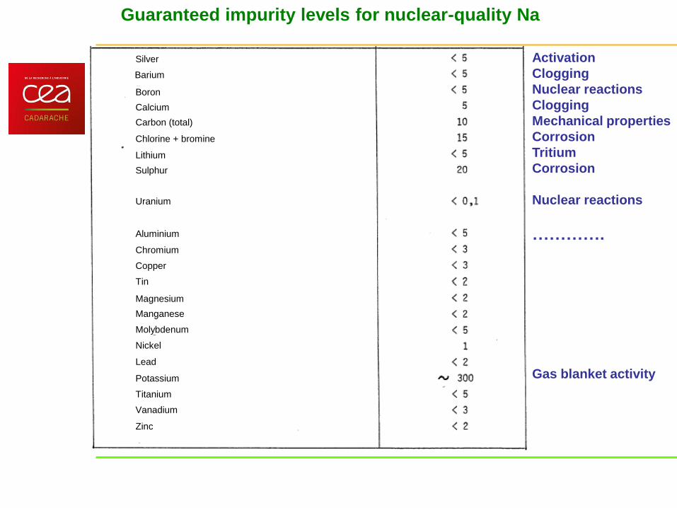
Guaranteed impurity levels for nuclear-quality Na
Activation
Clogging
Nuclear reactions
Clogging
Mechanical properties
Corrosion
Tritium
Corrosion
Nuclear reactions
………….
Gas blanket activity
Silver
Lead
Boron
Calcium
Carbon (total)
Chlorine + bromine
Lithium
Sulphur
Uranium
Chromium
Copper
Tin
Magnesium
Manganese
Molybdenum
Nickel
Barium
Potassium
Titanium
Vanadium
Zinc
Aluminium

Basic principle of Sodium Fast Reactor (Pool concept)
Steam
Generator
Intermediate
pump
Intermediate
Heat
Exchanger
Primary
pump
Slab Control
plug
Hot
plenum
Cold
plenum Energy
Conversion
System

Material for SFR subassemblies
DBTT

Needs of kinetics and knowledge on mechanical behaviour
As exemple: ODS
• Kinetics lower / 316 (weight gain by Ni)
• More sensitive to Carbon transfer ?
• Phase transformation due to Nickel transfer
(heater)
• No change in mechanical properties
• Needs :
– Oxidation data (ODS with very small grains :
lower oxidation rate expected ?)
– Phase transformation
– Long term prediction for normal and transient
operating conditions
(from JL Courouau GEDEPEON 2009 July 6th &7th)

Corrosion in primary Na of SFR
Sound austenite
Depleted Austenite
ferrite Na
Four successive stages are the following:
Stage 1: surface cleaning. This corresponds to the dissolution
of oxides and surface inclusions during the first hours. Mass
transfer during this stage is negligible.
Stage 2: austenite dissolution. At a temperature of 570°C or
more, the following stage is the dissolution of the austenite
layer in contact with the sodium and the diffusion of the steel
elements towards the sodium. If the temperature is lower than
590°C, the following stages are generally too slow and
practically do not occur.
Stage 3: formation of a ferrite layer. During a longer period of
time, at a temperature of more than 590°C, the diffusion of
elements from the external austenite layer leads to a
ferritization of the steel. This layer then dissolves and the steel
elements diffuse to the surface.
Stage 4: steady state behaviour. The ferrite layer reaches a
limit value ; its dissolution and the diffusion of elements to the
sodium is equivalent to stoichiometric corrosion of the basic
austenite. The contents reached et the sodium-steel interface
are of the order of 1 to 2% for nickel, 5 to 7 % for chromium
and less than 0.5% for manganese.
[O]< 5ppm, Pierre Baqué model
R = 0 (T< 817.13 K)
R = a . V 0.435 . [O] . exp(-150.5/(T-817.13))
R = mass loss in kg.m-2 per year
a = alloy-dependent coefficient
V = sodium rate (m/s) (< 10 m.s-1)
[O]= oxygen content in ppm (Eichelberger
law)
[O] > 5ppm, Alan Thorley model (for [O] between 0
ppm and high concentrations, but used in France
above 5 ppm and T>817.13 K)
If V 4 m/s, R = (V/4)0.435.104.724 +
1.106xlog10[O] - 3913/(T)
If V > 4 m/s, R = 104.724 + 1.106xlog10[O]-
3913/(T)
Fe Na-Fe-O
Na[O]
NaCrO2
Cr
Ni
Na[C] Cr23C6
Na[Ni]
Fe Na-Fe-O
sodium

Corrosion in sodium
Corrosion in the SFR: a key point even
if it has been shown that corrosion
rates in liquid sodium are very limited.
• In primary Na: generalized corrosion
(depends on material, temperature, O
content, Na velocity,..) mainly in fuel
cladding
• In intermediate Na: Na-water
interaction: generalized corrosion due
to Na-H2O interaction products.
• In all circuits, stress corrosion
cracking, mainly due to aqueous
NaOH at relatively low temperature….
To-TA
eO nvkr
Empirical models :
Phenomenological model :
)(.).(Re, )()( lsH aadDScShr
To-TA
eO nvkr Use restricted in duration, T, material, Re :
interpolation difficult and experiments required
For generalized corrosion:
Extrapolation possible
Core Fuel clad: A 15/15-25
Ti,
F/M 9-13-18Cr ODS
S. Assembly : F/M 9-
12 Cr
Fixed primary
structures
A 316 LN
Hot primary
structures and
components
(pump, heat ex)
A 316LN
F/M 9-12 Cr
Secondary
structure and SG
A 316 LN
F/M 9-12 Cr
Alternative
coolant or energy
conversion
systems
316L : Na-Ni
T91 : Pb- Bi
ScCO2

• Required data :
– Solubilities in liquid sodium (metallic and non-metallic elements)
– Free energies of formation
– Diffusivities in liquid sodium and materials
• Missing data : (see CRP IAEA next year)
– Solubilities V, Nb, B, W, Al,…
– Apparent solubilities of Fe
• 105 discrepancy assessed Fed+ FeOx + FeOyNat +
FeCz …
• Na4FeO3 =? (FeO)(Na2O)2)
• thermodynamic data (Fe – Na - C – O) system
– Diffusivities (all except Mn [Sudha, 2006])
0.01
0.1
1
10
100
200 300 400 500 600 700 800 900 1000T (°C)
S (
pp
m)
.
FeNiCrMoMn
0.001
0.01
0.1
1
10
100
1000
100 200 300 400 500 600 700T (°C)
S (
pp
m)
.
OHC
Needs of basic data for models
[Gnanasekaran, 1986]
(from JL Courouau GEDEPEON 2009 July 6th &7th)

CORRONa (CORROsion Na) Principle: thermal well with rotating cylinders
and sodium mini-loop for chemistry control - thermal well in gloves box for T control - inert crucible in contact with Na at high T to
avoid any contamination - Na recirculation (mini loop) for chemistry control - rotating cylinders to control hydrodynamics
Constraints : - make sodium fire a negligible risk (double
confinement, leaks detection, very low volume) - thermal control (cooling of the flange)
Corrosion testing device
CEA Saclay - Bat 458 pièce 3
a
b
Purification Purification Cylindre
éprouvette
Recirculation
Moteur
Cylindre
éprouvette
Recirculation
Moteur
LIBS A
Purificat
ion
A
Purificat
ion
1st wall 2nd wall
2 complementarily testing devices Na = 3.1 kg each Operating conditions: T = 500 - 625°C (designed for 750 °C) v = 500 - 10 000 tr/min (Re) [O] = 0,7 à 38 ppm Mini-loop : 1 L/h, 110-250°C with cold trap Crucible : Molybdenum (MLR – 0.7% La2O3) Well : Nickel base alloy 625
A A
(from JL Courouau GEDEPEON 2009 July 6th &7th)

Mass transfer:
•Transport of dissolved species (convective transport) and TH
•transport of particles if necessary(long term)
•Source term
• Use of a model of dissolution-corrosion for release
• Modelling of equilibrium Na liquid/ solid (long term)=> more thermodynamics
• Corrosion (ANACCONDA)
•Baque’s model ([O] below 5 ppm)
•Thorley’s model ([O] above 5 ppm)
Now OSCAR-Na code
•Activation: main sources of radioactivity:
• 58Co (71 days)
• 60Co (1913 days)
• 54Mn (313 days)
•Deposition
• 54Mn, 51Cr are dissolved in Na and mainly
deposited in the pumps and the coldest parts of the reactor (i.e. IHX)
• 60Co: low fraction diffused in hot surfaces
• Use of a model derived from Polley and Skyrme model for deposition
Needs of validation:
-“Contamination witness”
- Feedback from cleaning &
decontamination from SFR
-Basic knowledge (Acropolis,..
Mass brothers,…)
Mass Brothers
Objective : study of mass transfer from steel 316 (Z5 -CND
17 - 13) in PHENIX conditions
Test conditions
«core» : T = 400°C -> 690°C
«I.H.X.» : T = 600°C -> 400°C
[O2] = 0.7 ppm
duration : 23800 h
54Fe (n,p)
54Mn 312 d 834 keV
58Fe (n,)
59Fe 44 d 1099 keV
1291 keV 50
Cr (n,) 51
Cr 27 d 320 keV
58Ni (n,p)
58Co 71 d 811 keV
59Co (n,)
60Co 5 y 1173 keV
1332 keV
Contamination
witness

Process for code development and validation
Requirement analysis
Validation
Simulation of real reactors
Experiments on loop
code
Architecture
Models integration
Code validation
Use
Modelling
Bibliography
- reactors
- description of elementary
chemical and physics
phenomena
- basic data
Phenomenological analysis
(hierarchical ranking)
Experimental caraterization - elementary model validation
- parameters determination
Choice of models to integrate in
OSCAR
release OSCAR V2.X
- code
- Validation dossier

Decontamination process before repairing (SPX process)
• SPm : Sulfo Phosphoric modified
• H2SO4 + H3PO4
• Duration : 6 hours
• Temperature : 60°C
Criteria for decontamination process
selection :
– Good efficiency
- low residual dosimetry
– Process easy to implement and
flexibility for various components
– low cost for effluent treatment,
chemical products
- Easy component requalification
prior to re-use
PHENIX - Intermediate Heat Exchanger I - Dose rate
0
500
1000
1500
2000
2500
elevation
µG
y/h
Before cleaning
After cleaning
After decontaminationPrimary sodium outlet
PHENIX IHX activity (exemple)
IHX contamination mainly
due to 137Cs, 54Mn, 60Co

O control strategy in the primary vessel
5 ppm (maximum acceptable value for the
operation of reactors during a limited period
[0-3 ppm] is generally the operational range
recommanded for SFR.
In case of pollution, in SPX, it was
allowed to operate in [3-5 ppm], during 1
month.
Complex behavior of Fe in Na:
Apparent solubilities of Fe
Fed+ FeOx + FeOyNat +
FeCz …
Na4FeO3 =? (FeO)(Na2O)2)
thermodynamic data (Fe – Na - C – O)
Necessity to :
- validate Na Quality requirements
- investigate metallic elements
(pure or complex) behaviour in
sodium (and obtain basic data ie
diffusivities, solubilities,…)
- develop Instrumentation (O
control)
- assess quality control
methodology

O-measurements
Electrolyte material compatible with sodium
Ternary oxides (NaZrO2…)
Grain boundary corrosion (impurities…)
High quality for electrolyte material
Good mechanical thoughness and tightness
To avoid Na leak and thorium debris
To avoid radioactive gas release
- Electrolyte with high density
- Efficient closing system design
Operating temperature: might be a criteria
for the choice of the reference system
High ionic conduction
yttria 8<x<17 % mol. (7-15%mas.)
(ThO2)1-x(Y2O3)x : Opt. 7,5%
molaire
High purity
High mechanical thoughness to
thermal shock
High density 98% (best 99%)
Small homogeneous grains
High purity
Fine design
High quality brazed connection
chemistry, thermal expansion,
Na compatibility

O-meter designs
Long tubes
Pt/air reference
Westinghouse
Pt/air reference
Oxyfra
Small cup Pellet
In/In2O3
Harwell
Interatom, GE, IGCAR
In/In2O3
Ga/Ga2O3
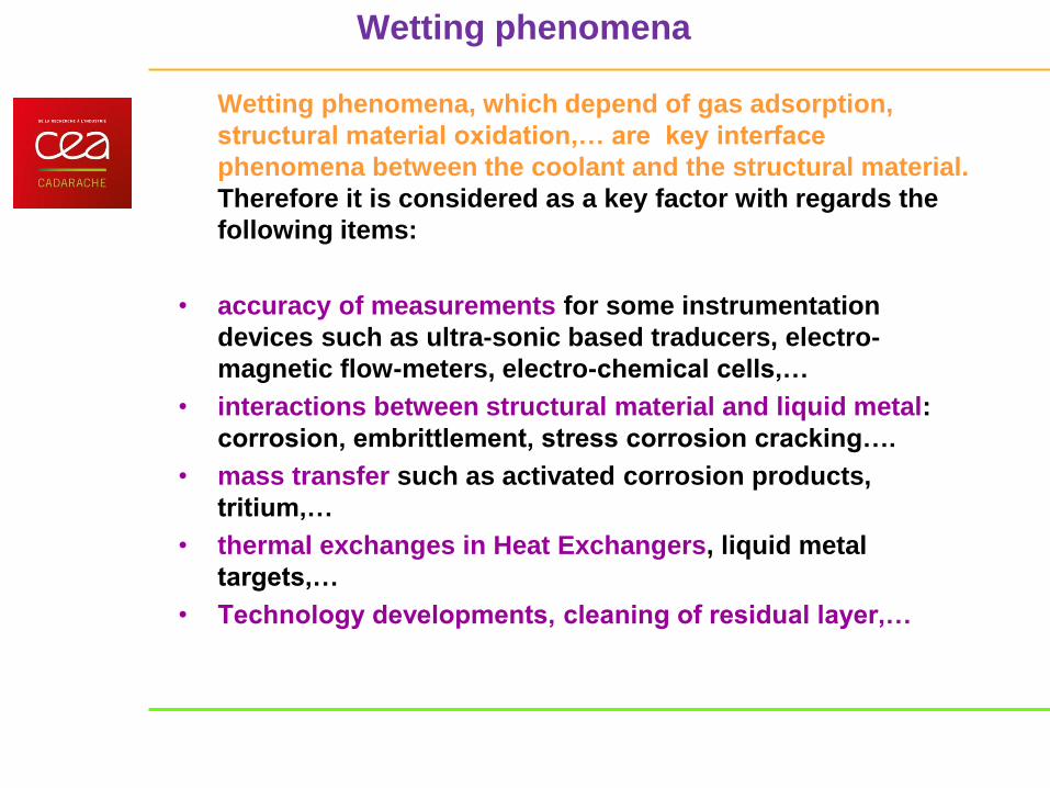
Wetting phenomena
Wetting phenomena, which depend of gas adsorption,
structural material oxidation,… are key interface
phenomena between the coolant and the structural material.
Therefore it is considered as a key factor with regards the
following items:
• accuracy of measurements for some instrumentation
devices such as ultra-sonic based traducers, electro-
magnetic flow-meters, electro-chemical cells,…
• interactions between structural material and liquid metal:
corrosion, embrittlement, stress corrosion cracking….
• mass transfer such as activated corrosion products,
tritium,…
• thermal exchanges in Heat Exchangers, liquid metal
targets,…
• Technology developments, cleaning of residual layer,…

Scientific Council G11 meeting on Wednesday, September 16th, 2009 at CEA/Cadarache
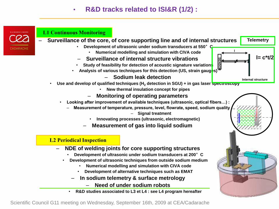
• R&D tracks related to ISI&R (1/2) :
– Surveillance of the core, of core supporting line and of internal structures
• Development of ultrasonic under sodium transducers at 550°C
• Numerical modelling and simulation with CIVA code
– Surveillance of internal structure vibrations
• Study of feasibility for detection of acoustic signature variations
• Analysis of various techniques for this detection (US, strain gauges)
– Sodium leak detection
• Use and develop of qualified techniques (H2 detection in SGU) + in gas laser spectroscopy
• New thermal insulation concept for pipes
– Monitoring of operating parameters
• Looking after improvement of available techniques (ultrasonic, optical fibers…) :
– Measurement of temperature, pressure, level, flowrate, speed, sodium quality …
– Signal treatment
• Innovating processes (ultrasonic, electromagnetic)
– Measurement of gas into liquid sodium
L1 Continuous Monitoring
L2 Periodical Inspection – NDE of welding joints for core supporting structures
• Development of ultrasonic under sodium transducers at 200°C
• Development of ultrasonic techniques from outside sodium medium
• Numerical modelling and simulation with CIVA code
• Development of alternative techniques such as EMAT
– In sodium telemetry & surface metrology
– Need of under sodium robots • R&D studies associated to L3 et L4 : see L4 program hereafter
Internal structure
l
l= c*t/2
Telemetry
SE
NS
OR
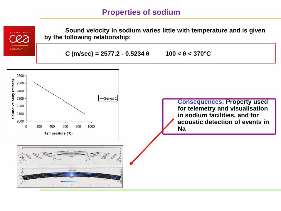
Properties of sodium
Sound velocity in sodium varies little with temperature and is given by the following relationship:
C (m/sec) = 2577.2 - 0.5234 100 < < 370°C
Consequences: Property used for telemetry and visualisation in sodium facilities, and for acoustic detection of events in Na
2000
2100
2200
2300
2400
2500
2600
0 200 400 600 800 1000
Temperature (°C)
So
un
d v
elo
cit
y (
m/s
ec)
Série1Series 1

Trapping gas pockets at the solid-liquid interface if :
Non wetting solid-liquid system
The roughness is such that [Johnson69] :
slope discontinuities exceeding Y
la << lc la : crevices size
lc : capillary length = gLV
Trapping gas pockets at the solid-liquid interface
Non-wetting system :
y > 90°
Rough solid surface
Liquid
Solid Gas

Acoustic coupling of ultrasonic transducers for SFR In-Service Inspection
Sodium temperature and Magnitude of the transmitted signal as a function of time
250
275
300
325
350
375
400
0 5 10 15 20 25 30 35 40 45 50 55 60 65 70 75 80
Time (h)
Te
mp
era
ture
(°C
)
0
10
20
30
40
50
60
70
80
90
Ma
gn
itu
de
pe
ak
-to
-pe
ak
(m
V)
T Na (°C)
Mpp (mV)

Acoustic coupling between two media = Acoustic waves transmission at the interface
Issue : acoustic coupling
During periodic examinations of the reactor at shutdown, TNa
180°C.
However, without special precautions, when a TUSHT is immersed
in sodium for the first time at this temperature, its acoustic
coupling is not achieved. Current solution : gold plating* surcharge, tricky implementation
*Gold plating the active face of the sensor under vacuum makes it possible
to achieve the acoustic coupling of the TUSHT at ~110°C
liquid
sodium
TUSHT
Structure to
be inspected
Acoustic
coupling
Ultrasound
Good acoustic coupling between sodium
and the active face must be achieved.
(TUSHT = Traducteur UltraSonore Haute Température)
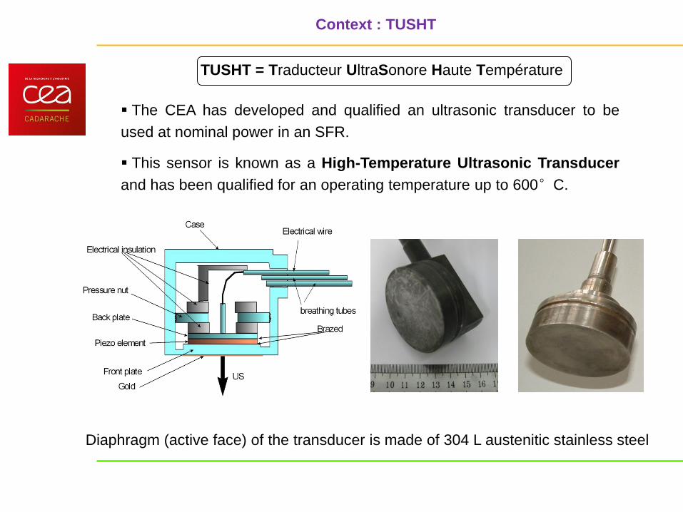
TUSHT = Traducteur UltraSonore Haute Température
The CEA has developed and qualified an ultrasonic transducer to be
used at nominal power in an SFR.
This sensor is known as a High-Temperature Ultrasonic Transducer
and has been qualified for an operating temperature up to 600°C.
Context : TUSHT
Diaphragm (active face) of the transducer is made of 304 L austenitic stainless steel

L3 Special Inspection
L4 Repair
Scientific Council G11 meeting on Wednesday, September 16th, 2009 at CEA/Cadarache
Study of a global intervention, with :
- Defueling : see « Fuel Handling » studies
• Need of in sodium handling with external storage
- Sodium draining of reactor block :
• Analysis of needs ans associated durations
• Need to prevent caustic corrosion
- Televisual and volumetric inspection in radiating environment
- Sodium filling
- Refuelling
- Repair operations are done in gas atmosphere (can induce defueling and sodium draining)
- Study of in sodium tightness (design of under sodium bell)
- Analysis of tools for repair :
• Sodium traces to be swept (gas blowing/brushing/laser...)
• Machining (milling/grinding/laser…)
• Welding (TIG/laser…)
- Need of under sodium robots assuming efforts of repair tools :
• Analysis of available materials
• Definition of specific robots
• R&D tracks related to ISI&R (2/2) :

Other risk: stress corrosion cracking

Overview on materials

Basic principle of Sodium Fast Reactor (Pool concept)
Steam
Generator
Intermediate
pump
Intermediate
Heat
Exchanger
Primary
pump
Slab Control
plug
Hot
plenum
Cold
plenum Energy
Conversion
System

Main issue: Na-H2O mitigation
Na + H2O NaOH + ½ H2 – 141 kJ/molNa
Na
Water
Steam Generator
750 MW

Sodium-water reaction
Na
H2O
SGU Na-H2O : a violent and exothermal chemical reaction
Main reaction
Na + H2O NaOH + ½ H2 + 162 kJ/water mole (at
500°C)
Complete, quasi-instantaneous and non-reversible
reaction
Many secondary reactions
2Na + NaOH 2 1 [O2-]Na + [H-]Na Na2O + NaH
Equilibrium reaction depending on sodium
temperature and hydrogen dissolved and hydrogen
partial pressure equilibrium
Above about 300°C, and with sodium in excess,
hydroxide is decomposed in sodium oxide and
hydride (reaction 1)
Above 410°C, reaction (2) occurs only if PH2
reach Pequilibrium in cover gas; The experimental
conditions doesn’t satisfy this condition; Thus the
decomposition of NaOH is total.
Reaction rates depend on temperature
ORIGINS : Normal operation of steam generator induces
damage of heat exchange tubes
tube corrosion : mainly in welding zones, inducing leaks
due to cracking
thermal chocks : when under-saturated water is injected at
super heater inlet (Phenix), inducing thermal fatigue,when
fluctuation of heat exchange conditions
impossible tube expansion: buckling, inducing
differential expansion with envelope
tube bundle vibrations : hydraulic effect of sodium flow,
inducing tube wear
1200°C Pressure
Temperature
Time (s) Time (s)
Effects: chemical,
mechanical,
thermal
No leak Micro leak small leak evolution

Wastage effect

Sodium-water reaction
Excellent operational feedback from Phenix &
SPX (and also from international feedback)
; nevertheless tracks for improvement:
Reduction of Na transit time
Signal processing
Other (complementary?) solutions to be deeply
analysed
(Acoustic detection, electrochemical H-meter,…)
Electro-chemical H-meter
(Courtesy of IGCAR)

Lead-bismuth properties (55.5% Bi):
- Low melting point (125°C)
- No chemical reaction with water (but it may
violently vaporise depending on conditions )
- Lead oxidised with possible precipitation of PbO
- Significant corrosion, protective coating
necessary: Aluminium coatings, or oxygen
content controlled to maintain a protective
oxide film at the surface (introduction of
steam+H2 or oxygen by an equilibrium
method using PbO pellets)
- Possible interaction with Na: Exothermal formation of BiNa3 (137 kJ/mol LBE)
- Very large operating feedback available on this coolant in ADS, especially with spallation targets (TECLA, MEGAPIE, EUROTRANS, VELLA programmes)
0,010
1E-11
1E-09
1E-07
1E-05
0,001
0,1
10
100 200 300 400 500 600 700
T (°C)
Co
, p
pm
EPB
Contamination
Oxydation Dissolution
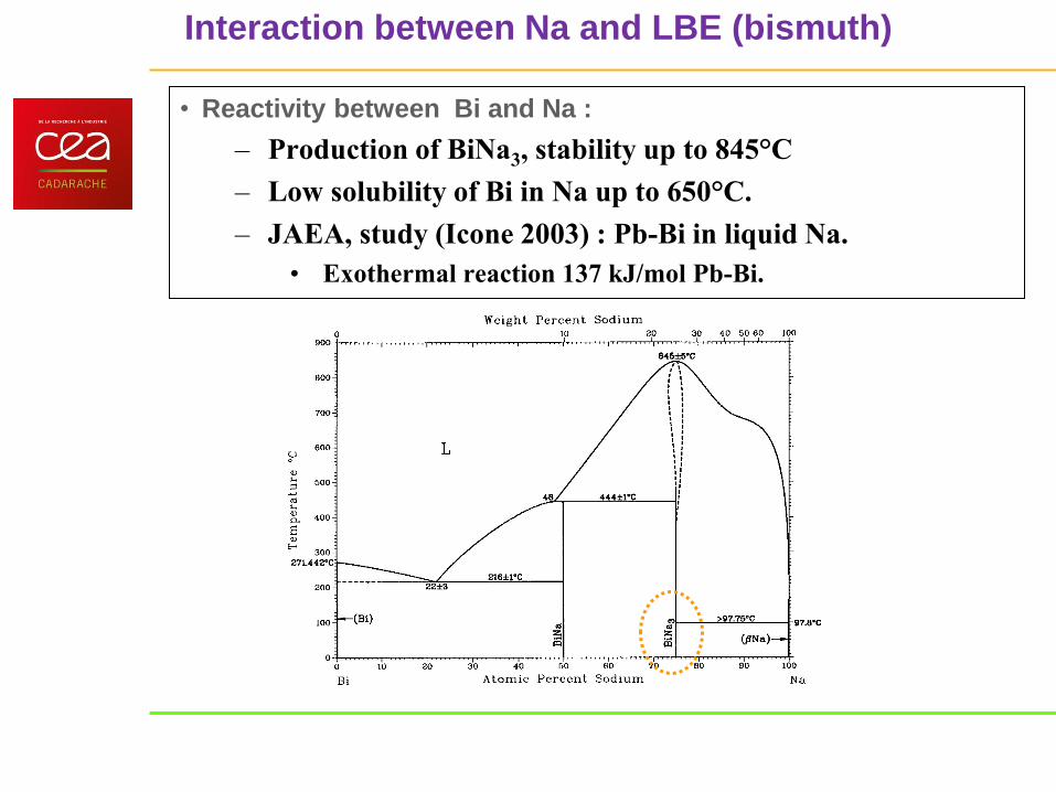
• Reactivity between Bi and Na :
– Production of BiNa3, stability up to 845°C
– Low solubility of Bi in Na up to 650°C.
– JAEA, study (Icone 2003) : Pb-Bi in liquid Na.
• Exothermal reaction 137 kJ/mol Pb-Bi.
Interaction between Na and LBE (bismuth)

Corrosion phenomenology after sodium leak
Impact of the thermal insulation system
Sodium temperature effect :
- at low temperature (350°C) : outside
radial migration (by capillary)
predominates rather than migration to the
wire detector located in the lower 180°
cone distance (BPR and RUR tests)
- at high temperature, the sharper reaction
between sodium and the heat insulation
material creates a shell of reaction
products limiting the rise of sodium by
capillary (RUR tests)

Corrosion studies
Zone 1 : Na almost pur and material without any significant corrosion
Zone 2 : solid magma dark greyish : oxides (Na2SiO2)
Zone 3 : brittle and rather green (presence of metallic ions Fe++, Fe+++, Cr++)
Zone 4 : layer very green with mainly Na2O
The main result is the identification of a typical
corrosion mechanism called « anodic
dissolution », confirmed by other tests (Mod); it is
mainly due to sodium pulverizationduring its
propagation in the insulating material and
subsequent oxidation.
The oxygen content increases near the surface of
the insulating material (at the Na interface) (very
similar to the so-called corrosion phenomena in
wet conditions « Pile of Evans »)
A tool for the designer and manufacturer
Design and Construction Codes for SFR
RCC-MR/RCC-MRx
(from a contribution from Odile Gelineau AREVA
in CP-ESFR Seminar))
CODE = tool providing sets of requirements on materials procurement, design, analysis,
construction qualifications, examinations, surveillance and tests
Rules based on feedback from relevant industrial experience
It provides several advantages :
- Guide for the designer : checklist of all necessary verifications
- Provide an overall consistency to guarantee the structural integrity of a component
- Make easier relationships (and clarify contractual dialog) between Sub-contractors, Manufacturers and Suppliers (and Safety Authorities)
- Reduce costs and improve efficiency through standardisation : simplify the documents, the practices

41 ESFR SP5 - Education &Training - Sodium behaviour and safety – CEA Cadarache 16-11-2010
Intermediate Heat eXchanger :
Tnom : 400°C < 550°C Pnom : 4 bars
Na/Na
Steam Generator :
Tnom (Na) : 345 < 525°C –
Tnom (H2O) : 240 <490°C
Pnom : 190 Bars
Na/H2O
Secondary Circuit :
Tnom : 345<525°C
Pnom : 4 bars
Na
Vessels, internals:
Tnom : 400 < 550°C
Na
SFR specificity and RCC-MR

42 ESFR SP5 - Education &Training - Sodium behaviour and safety – CEA Cadarache 16-11-2010
The RCC-MR code has been developed to take into account
those specificities :
• Significant Creep and associated
damage modes (time-dependent damages)
• Sensitivity to Buckling
• Materials able to sustain high temperatures
• Design rules for particular components
SFR specificity and RCC-MR
Time-dependent fracture
Shear
buckling
It has been presented to French Safety Authorities and used for:
- The design and construction of components for SUPERPHENIX and PHENIX (Heat Exchangers, Pumps, Tanks, pipes,…)
- The design of European Fast Reactor
- The studies for the lifetime extension of PHENIX
- The Indian PFBR
- The SFR project
- The Vacuum Vessel of ITER

43 ESFR SP5 - Education &Training - Sodium behaviour and safety – CEA Cadarache 16-11-2010
Code organization : RCC-MR/RCC-MRx
Sections Contents
Section 1
Equipements
General requirements
Design rules for : Class 1, 2, 3 components and their
supports, for handling mechanisms
Technical Appendices with material databases in
appendix A3
Section 2 Materials
Section 3 Examination and testing methods
Section 4 Welding
Section 5 Fabrication

44 ESFR SP5 - Education &Training - Sodium behaviour and safety – CEA Cadarache 16-11-2010
• Materials (Section 2) :
– Material selection
– Material Reference Specifications taking into account
experience of procurements
• Give process for a part qualification
• Examination and testing methods (Section 3)
– Physical and mechanical testing methods
– Current NDE practices
– Qualification and certification of NDE personnel
• Welding (Section 4) :
– Acceptable filler materials and their procurements
– Acceptance tests
– Reference data sheets
– Acceptable welding procedure and their qualification
• Fabrication (Section 5)
– Forming and tolerances
– Surface treatments, Rules for cleanliness
Code organization - The Other Sections

45 ESFR SP5 - Education &Training - Sodium behaviour and safety – CEA Cadarache 16-11-2010
Code organization
Consistency
of technical
provisions in
each section
of the code

46 ESFR SP5 - Education &Training - Sodium behaviour and safety – CEA Cadarache 16-11-2010
An application : damage modes in a SFR
Shear
Buckling
Buckling
under
Pressure
Excessive
Deformation
Vibration
Fatigue Fatigue under
thermal transients
High cycle
Fatigue
Progressive
deformation
Creep-Fatigue

Thank You very much for your kind attention!

A free level of sodium exits in the main vessel, above the core
and under the upper closure of the vessel.
This provision allows for an easier design and operation of all
the penetrations in the vessel that
are necessary for (either during operation or maintenance):
- fuel handling in the core,
- movement of core control devices
(neutrons absorber rods),
- core monitoring (instrumentation),
- handling of components other than fuel,
that are located in the vessel (core feed pipes,
pumps, heat exchangers, according to the
design of the reactor,
- in service inspection of the vessel and its
internal structures.
It is necessary to have a correct knowledge of key
phenomena in the cover gas:
- Heat transfer, that occurs according to different mechanisms,
mainly: .convection in gas,
.radiation from the sodium surface towards
emerged structures,
-Mass transfer: evaporation / condensation of sodium vapours.
- Sodium deposits.
Shématisation des processus de transfert de l'oxygène :Figure 1 :
Transfert par diffusion au travers de la couche limite
Transfert par diffusion au travers de la pellicule d'oxyde
Transfert par diffusion au travers de la couche limite
Ciel d'Argon
Sodium Liquide
Transfert par convection naturelle
Transfert par convection
Purification par cristallisationd'oxyde de sodium sur piège froid
Injection oxygène
dans le ciel d'argon
dissolution de la pellicule d'oxyde
Réaction chimique
à l'interface pellicule / Na ( l )
Na
Argon
Contamination (ie 137Cs)
Heat and mass transfer in the Upper gas plenum


![Na+[Me3NB12Cl11]−·SO2: a rare example of a sodium–SO2 …](https://img.dokumen.tips/doc/110x75/62610a45e6160445a625631b/name3nb12cl11so2-a-rare-example-of-a-sodiumso2-.jpg)


