Embed Size (px)
Citation preview

JPS Communications’Receiver Voter fami-ly, which includes theSNV-12, is equippedwith a variety ofmeans for problemsolving in receivervoter applications.
SNV-12 Signal-And-Noise VoterLand Mobile
IntroductionThe SNV-12 voter comparator from RaytheonJPS Communications soves radio system talk-in problems. It monitors multiple remotereceivers on a radio channel, and selects thebest signal. The incoming signal with the low-est noise is selected; this is usually from thereceive site closest to the transmitting portableor mobile. The SNV-12 monitors up to twelvereceiver audio inputs per chassis and sends thebest signal to the dispatcher and/or repeats itover the air.
One of the most common receiver voting appli-cation is for a single duplex repeater and multi-ple auxiliary receivers. The voter can also beutilized in simplex applications. Additionally, theSNV-12 can be configured to handle complexapplications controlling multiple repeaters ortransmitters.
The SNV-12 works on 2175Hz pilot tone,1950Hz pilot tone, or E-lead COR (CarrierOperated Relay contact closures) to detectwhen a receiver has unsquelched. It generatesboth EIA keytones and M-Lead PTT (Push ToTalk) outputs for keying transmitters. Examplesare shown of the following typical receiver vot-ing system configurations:
! Figure 1: Pilot tone internally generated inreceiver, EIA keying
! Figure 2: Pilot tone externally generated, EIAkeying
! Figure 3: E-Lead squelch indication, PTT key-ing
! Figure 4: Pilot tone internally generated, RFlinked, hardwired PTT
The SNV-12 voter software resides in the cen-tral processing module and is flashed downinto all other modules. Customers can enable/disable all voter functions via dip switches.
An SNV-12 voter chassis holds up to 12 sitemodules. Each site module is interfaced to anindividual receiver. Up to three chassis can beconnected together, allowing up to 36 sites tobe voted.
This application note illustrates the use of theSNV-12 in conventional (non-trunked) radiosystems.
Voting Remote Receivers whichhave Internal Pilot ToneGeneratorsThe most common installation of theSNV-12 voter is illustrated in Figure 1. In thisinterconnection drawing, a duplex system witha single transmitter and multiple receivers isshown. The additional receivers assist the fieldunits in reaching dispatch and other field units.Since this is a duplex system, portables ormobiles transmit on f1 and receive on f2. Theremote receivers shown are tuned to f1 and arelocated throughout the region for maximumcoverage. Transmissions from the field can berouted to dispatch and/or repeated over thesame high-powered base station transmitter(TX1), that is used for dispatch transmissions.This transmitter should be capable of beingheard by portables and mobiles throughout thedesired coverage area.
Most voting receivers produce pilot tones whennot receiving audio or carrier from a field unit.Each remote receiver shown in Figure 1 gener-ates a 2175 Hz pilot tone. The pilot toneremains on until the receiver senses a carrierwith the correct CTCSS tone, it then removesthe pilot tone and sends the received signal tothe voter. This audio / pilot tone signal can besent back to the SNV-12 from the remote siteover a wide variety of transmission paths.Audio can be sent via a dedicated twisted pair,a telco 4-wire circuit, a microwave link, or anRF link. Audio reaches a DSP (Digital SignalProcessor) in each site voter module (SVM).The DSPs sample the incoming RX audio sig-
A P P L I C ATION NOTES
JPS Communications, Inc.5800 Departure DriveRaleigh, NC 27616
Phone: (919) 790-1011Fax: (919) 790-1456E-Mail: [email protected]: www.jps.com
Specifications subject to change without notice.Copyright © 2004 JPS Communications. All rights reserved.
Ver.1 3/04

A P P L I C ATION NOTESSNV-12 Signal-And-Noise Vo t e r
nals and use sophisticated proprietary algorithms to calculate asignal quality number for each SVM. The signal quality number isfed to the micro-controller in the CPM-1 module, which selectsthe best of these signals and routes it to the console and therepeater.
Refer again to the voting system depicted in Figure 1. The pres-ence of a pilot tone on the incoming audio pair signals that thereceiver is squelched; the SNV-12 votes the best quality RX sig-nal from among all sites that do not have pilot tones. This votedsignal is sent on to the dispatch console, and if the “RepeatMode” feature is enabled in the SNV-12, the voted audio is mixedwith the EIA keying tone sequence and sent to the systemtransmitter.
The pilot tones also provide a means for the voter to detect afailed receiver or broken link to the receiver. If the voter does notreceive a pilot tone from a receiver, it assumes that the receiveris unsquelched; therefore a voice signal should be forthcoming.If the voice signal doesn’t show up after a set time period, it isclear that the receiver or the line to the receiver has failed and
that site is removed from voting consideration. The failed site isindicated by the illumination of the FAULT light on the Site VoterModule’s front panel. The use of identical voting receivers in alllocations is recommended so that the received audio soundssimilar whichever site is voted. This creates a better audio signalto the dispatcher as the voter switches between receiver sites.
Input audio delay is available in each Site Voter Module to com-pensate all incoming audio paths – for example, if one circuit iscoming in on a very compressed microwave link with an addi-tional 120 milliseconds of modulate / demodulate time, then allother channels should be delayed by the same amount soswitching occurs on the same syllable. Potential variations onFigure 1 include the use of a 1950 Hz pilot tone instead of 2175;the use of PTT keying instead of EIA keytones; or to operatewithout the Repeat Mode enabled (in other words, field commu-nications are not retransmitted and are heard only by thedispatcher.).
Figure 1 2175 Hz Pilot Tone
generated in receiver
EIA tone keying
Alternatives 1950 Hz Pilot Tone
PTT keying
RaytheonJPS Communications
SNV-12
ConsoleTx Audio
w/EIA Keytones
Voted Audio
Tx1 Rx1
Rx Audio / 2175 Hz Pilot Tone
Tx Audio with EIA Keytones
f2f1
Rx12 Rx Audio / 2175 Hz Pilot Tone
f1
Rxn Rx Audio / 2175 Hz Pilot Tone
f1
Rx2 Rx Audio / 2175 Hz Pilot Tone
f1
A P P L I C ATION NOTESSNV-12 Signal-And-Noise Vo t e r
Voting Remote Receivers which requireExternal Pilot Tone GeneratorsAnother typical configuration for the SNV-12 voter is illustratedin Figure 2. This is basically identical to Figure 1, except that thevoting receivers did not have the capability to generate pilot toneinternally. The Raytheon JPS Model PTG-10 is shown installed ateach remote receiver site. The PTG-10 injects pilot tone onto theRX audio pair whenever the receiver is squelched. This allowslow cost base stations (or even mobile receivers), to be usedinstead of expensive voting receivers. Variations on Figure 2again include the use of a 1950 Hz pilot tone instead of 2175; theuse of PTT (E&M) keying instead of EIA keytones; or to operatewithout the Repeat Mode enabled.
Voting Remote Receivers and using COR(E-Lead) InputsIn Figure 3, the SNV-12 uses an E-lead input from each remotereceiver to determine when that receiver is unsquelched. Thisconfiguration is typically utilized in microwave or telco T1 config-urations where a customer controlled multiplexer or channelbank passes E&M signaling. The E-lead can be either high goingor low going at multiple voltage levels from remote receivers, inother words, signaling types I, II, III, or V. In this Figure, theCOR from the remote receiver feeds an input on the multiplexerin the remote site, causing an E-lead output at the local site tofeed the SNV-12. As in Figures 1 and 2, if the Repeat Mode isenabled, the voted audio is retransmitted by the system repeaterat site #1.
Figure 22175 Hz Pilot Tone
externally generated
EIA tone keying
Alternatives 1950 Hz Pilot Tone
PTT keying
RaytheonJPS Communications
SNV-12
ConsoleTx Audiow/EIA Keytones
Voted Audio
Tx1 Rx1
Tx Audio with EIA Keytones
f2f1
Rx Audio / 2175 HzRx AudioUnsquelch
CORPTG-10
Rxn
f1Rx Audio / 2175 HzRx Audio
UnsquelchCOR
PTG-10
Rx2
f1Rx Audio / 2175 HzRx Audio
UnsquelchCOR
PTG-10
A P P L I C ATION NOTESSNV-12 Signal-And-Noise Vo t e r
Figure 3E & M COR
PTT keying
Console
PTT
Tx Audio
Voted Audio
Tx1 Rx Audio Unsquelch COR
PTTTx Audio
f2f1
Rx1
f1
Rx Audio Unsquelch COR E LeadMUX MUXRxn
f1
Rx Audio Unsquelch COR E LeadMUX MUXRx2
RaytheonJPS Communications
SNV-12
Figure 4RF Linked System
Tx1 Rx1 Rx Audio / 2175 Hz
Tx Audio with EIA Keytones
f2f1
ConsoleTx Audiow/ EIA Keytones
Voted Audio
RaytheonJPS Communications
SNV-12
Rx Audio /2175 Hz
Rx Audio /2175 Hz
f1
RxnLink Tx Link Rx
Rx Audio /2175 Hz
Rx Audio /2175 Hz
f1
Rx2Link Tx Link Rx
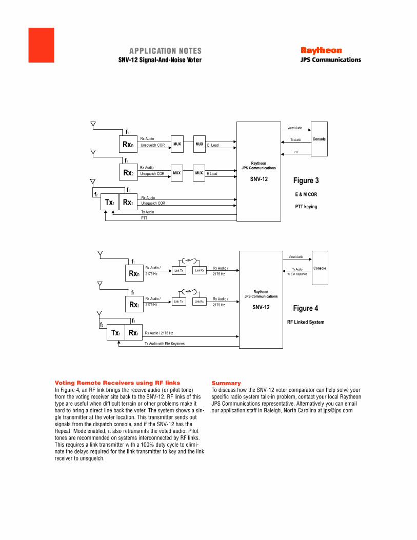
Voting Remote Receivers using RF linksIn Figure 4, an RF link brings the receive audio (or pilot tone)from the voting receiver site back to the SNV-12. RF links of thistype are useful when difficult terrain or other problems make ithard to bring a direct line back the voter. The system shows a sin-gle transmitter at the voter location. This transmitter sends outsignals from the dispatch console, and if the SNV-12 has theRepeat Mode enabled, it also retransmits the voted audio. Pilottones are recommended on systems interconnected by RF links.This requires a link transmitter with a 100% duty cycle to elimi-nate the delays required for the link transmitter to key and the linkreceiver to unsquelch.
SummaryTo discuss how the SNV-12 voter comparator can help solve yourspecific radio system talk-in problem, contact your local RaytheonJPS Communications representative. Alternatively you can emailour application staff in Raleigh, North Carolina at [email protected]