Embed Size (px)
Citation preview

Subject to change – H. Gsoedl, B. Rott 04.07 – 7BM66_0E
Products: R&S®DVM50, R&S®DVM100, R&S®DVM100L, R&S®DVM120, R&S®DVM400
SNMP Example: DVM Management Center Monitoring in a Broadcast Network
Application Note The simple network management protocol (SNMP) can be used in a wide range of applications, as described in Rohde & Schwarz Application Note 7BM65 “The Simple Network Management Protocol: Remote Controlling for Monitoring Devices“ [1]. In particular, the option of centrally managing monitoring sensors – such as the R&S®DVM for RF and baseband signals in digital broadcasting – shows the potential of this technology. However, the protocol alone is not enough to achieve this management functionality. Specialized management applications are needed that carry out the SNMP requests and display the results graphically.
This application note and the associated SNMP example application will show how the R&S®DVM family can be used for this type of application. Rohde & Schwarz customers can use the included source code (programming language: C#) to make the modifications needed for their own situations.
SNMP Example: DVM Management Center
7BM66_0E 2 Rohde & Schwarz
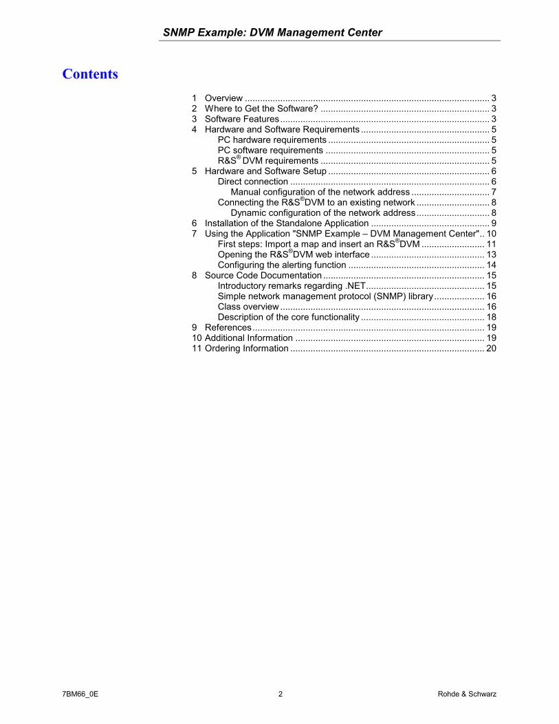
Contents 1 Overview ................................................................................................. 3 2 Where to Get the Software? ................................................................... 3 3 Software Features................................................................................... 3 4 Hardware and Software Requirements ................................................... 5
PC hardware requirements ................................................................ 5 PC software requirements ................................................................. 5 R&S® DVM requirements ................................................................... 5
5 Hardware and Software Setup ................................................................ 6 Direct connection ............................................................................... 6
Manual configuration of the network address ............................... 7 Connecting the R&S®DVM to an existing network ............................. 8
Dynamic configuration of the network address............................. 8 6 Installation of the Standalone Application ............................................... 9 7 Using the Application "SNMP Example – DVM Management Center".. 10
First steps: Import a map and insert an R&S®DVM ......................... 11 Opening the R&S®DVM web interface ............................................. 13 Configuring the alerting function ...................................................... 14
8 Source Code Documentation ................................................................ 15 Introductory remarks regarding .NET............................................... 15 Simple network management protocol (SNMP) library.................... 16 Class overview ................................................................................. 16 Description of the core functionality ................................................. 18
9 References............................................................................................ 19 10 Additional Information ........................................................................... 19 11 Ordering Information ............................................................................. 20

SNMP Example: DVM Management Center
7BM66_0E 3 Rohde & Schwarz
1 Overview The simple network management protocol (SNMP) can be used in a wide range of applications, as described in Rohde & Schwarz Application Note 7BM65 “The Simple Network Management Protocol: Remote Controlling for Monitoring Devices“ [1].
In particular, the option of centrally managing monitoring sensors – such as the R&S®DVM for RF and baseband signals in digital broadcasting – shows the potential of this technology. However, the protocol alone is not enough to achieve this management functionality. Specialized management applications are needed that carry out the SNMP requests and display the results graphically.
This application note and the associated SNMP example application will show how the R&S®DVM family can be used for this type of application. Rohde & Schwarz customers can use the included source code (programming language: C#) to make the modifications needed for their own situations.
2 Where to Get the Software? The example application and the associated source code can be downloaded with this document from the Application Notes area of the Rohde & Schwarz homepage. In addition to the archived project, a standalone installation routine is also available.
3 Software Features The application “SNMP Example: DVM Management Center” polls the connected R&S®DVMs within the network every 7 seconds and checks the alarm states of their RF and baseband inputs. Based on the poll results, the overall alarm state of each R&S®DVM is displayed on a user-defined graphic (e.g. a map). The following states are possible:
• Red: Alarm is present at one of the inputs.
• Yellow: An alarm was present in the past, but currently there is no alarm at
any input.
• Green: No current or past alarm at any of the inputs.
• Connectivity loss: No network connection to the device, or SNMP service
not available.

SNMP Example: DVM Management Center
7BM66_0E 4 Rohde & Schwarz
To illustrate the polling principle at the inputs of an R&S®DVM, three possible
polling examples are shown here:
Fig. 1: Polling principle
As illustrated here, the polling process queries the current state of the inputs. Any "interim states" are not included.
An optional e-mail notification of the alarm states is possible. The user can define the following alert criteria (sorted by alarm level):
1. Connectivity Loss: After X (= number) sequential Connectivity Loss states, an
e-mail is sent.
2. TS Sync Loss: After X (= number) sequential TS Sync Loss states, an alarm is
issued for TS Sync Loss.
3. Continuous Alarm State: After X (= number) sequential Alarm states, an alarm
is issued for Continuous Alarm State.
4. Entry in Alarm Report: If an alarm state is currently detected, or if an alarm
state had been detected in the past, an alarm is immediately issued by making
an entry in the Alarm Report.
Polling result 1: Polling result 2:
Polling result 1:
Polling result 1:
Polling result 3: Polling result 4:
Polling result 2: Polling result 3: Polling result 4:
Polling result 2: Polling result 3: Polling result 4:
No current or past alarm.
An alarm was present in the past, but currently there is no alarm.
Alarm is present.
LED status on device
LED status on device
LED status on device

SNMP Example: DVM Management Center
7BM66_0E 5 Rohde & Schwarz
To prevent multiple notifications about an existing, persistent alarm state, it is possible to set an alarm delay. This means that if one of the above alarm states occurs, a delay is activated for any subsequent notifications based on the critical alerting condition.
Finally, the graphical map display serves as the interface to the web interface of the R&S®DVM. Users can click on the corresponding symbol in the map to open a web display that allows closer observation of the monitoring states of the R&S®DVM.
4 Hardware and Software Requirements
PC hardware requirements
Minimum
CPU Pentium II 450 MHz or better
RAM 128 Mbyte
Hard Disk 50 Mbyte free hard disk space
Monitor SVGA color monitor, resolution 1024 x 768 or better
PC software requirements
Minimum
OS Windows 98 / 2000 / Me / XP
OS add-ons
.NET Framework 2.0 or better
Java 2 Plattform Standard Edition 1.5.0 or better
R&S® DVM requirements Please make sure that R&S® DVM firmware 4.10 or better is installed. Furthermore ensure that the required web server for the web interface is running. For installation instructions, please refer to the documentation for FW 4.10.
SNMP Example: DVM Management Center
7BM66_0E 6 Rohde & Schwarz
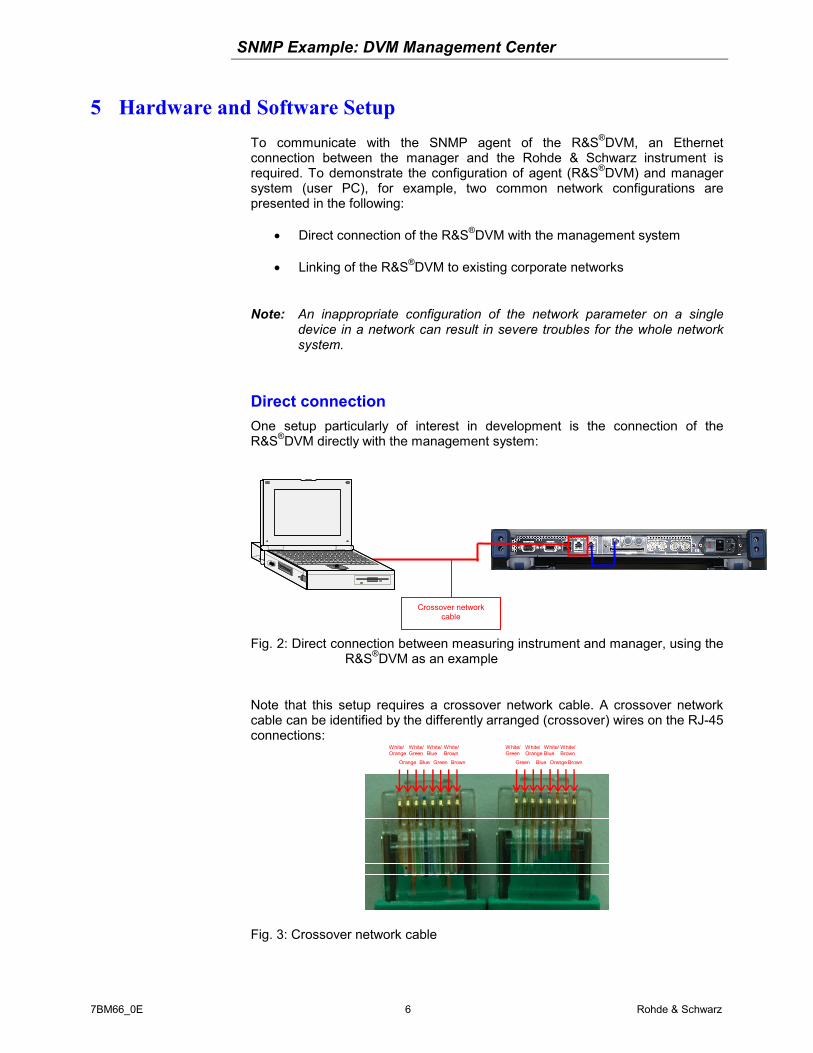
5 Hardware and Software Setup To communicate with the SNMP agent of the R&S®DVM, an Ethernet connection between the manager and the Rohde & Schwarz instrument is required. To demonstrate the configuration of agent (R&S®DVM) and manager system (user PC), for example, two common network configurations are presented in the following:
• Direct connection of the R&S®DVM with the management system
• Linking of the R&S®DVM to existing corporate networks
Note: An inappropriate configuration of the network parameter on a single device in a network can result in severe troubles for the whole network system.
Direct connection One setup particularly of interest in development is the connection of the R&S®DVM directly with the management system:
Fig. 2: Direct connection between measuring instrument and manager, using the R&S®DVM as an example
Note that this setup requires a crossover network cable. A crossover network cable can be identified by the differently arranged (crossover) wires on the RJ-45 connections:
Fig. 3: Crossover network cable
White/ Orange
Crossover network cable
Orange
White/ Green
Blue
White/ Blue
Green
White/ Brown
Brown
White/ Green
Green
White/ Orange
Blue
White/ Blue
Orange
White/ Brown
Brown

SNMP Example: DVM Management Center
7BM66_0E 7 Rohde & Schwarz
Manual configuration of the network address Both the management system and the R&S®DVM must be configured properly with respect to the network address. As discussed in section 3, both instruments must be logically located in one subnet.
For example, the following address configuration may be used:
Manager R&S® DVM
IP address 192.100.10.201 192.100.10.202
Subnet mask 255.255.255.0 255.255.255.0
To obtain the network configuration of a fixed IP address, proceed as follows under Windows:
1. Using the right mouse button, click My Network Places and select Properties.
2. Right-click the required LAN adapter of the system; the properties of this network connection will be accessed.
Note:
In the case of the R&S®DVM, do not change the configuration of the Private Analyzer Network adapter.
3. Access the properties of the Internet Protocol (TCP/IP) entry.
4. Enter the IP address and subnet mask you want by enabling "Use the following IP address".
5. To accept your settings, close all windows with OK.
-
SNMP Example: DVM Management Center
7BM66_0E 8 Rohde & Schwarz
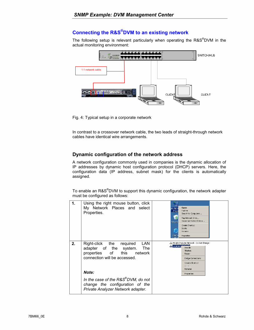
Connecting the R&S®DVM to an existing network The following setup is relevant particularly when operating the R&S®DVM in the actual monitoring environment:
1 2 3 4 5 6
7 8 9101112
AB
12x
6x
8x
2x
9x
3x
10x
4x
11x
5x
7x
1x
Ethe
rnet
A
12x
6x
8x
2x
9x
3x
10x
4x
11x
5x
7x
1x
C
Fig. 4: Typical setup in a corporate network
In contrast to a crossover network cable, the two leads of straight-through network cables have identical wire arrangements.
Dynamic configuration of the network address A network configuration commonly used in companies is the dynamic allocation of IP addresses by dynamic host configuration protocol (DHCP) servers. Here, the configuration data (IP address, subnet mask) for the clients is automatically assigned.
To enable an R&S®DVM to support this dynamic configuration, the network adapter must be configured as follows:
1. Using the right mouse button, click My Network Places and select Properties.
2. Right-click the required LAN adapter of the system. The properties of this network connection will be accessed.
Note:
In the case of the R&S®DVM, do not change the configuration of the Private Analyzer Network adapter.
1:1 network cable

SNMP Example: DVM Management Center
7BM66_0E 9 Rohde & Schwarz
3. Access the properties of the Internet Protocol (TCP/IP) entry.
4. Enable the DHCP configuration by selecting "Obtain an IP address automatically".
5. To accept your settings, close all windows with OK.
-
6 Installation of the Standalone Application 1. Double-click the application setup file to launch it:
2. The application checks whether .NET Framework, Version 2 or later is installed on the computer. If not, this software can be downloaded from the Internet and installed:
Click "Yes" to open the Microsoft download page:
From here, you can download the software at no cost.

SNMP Example: DVM Management Center
7BM66_0E 10 Rohde & Schwarz
3. After .NET Framework has been installed (or if it was already installed), simply follow the installation instructions provided in the setup routine.
4. After installation is complete, a link to the application is available in the Start menu under "Rohde & Schwarz":
7 Using the Application "SNMP Example – DVM Management Center"
This section describes how to use the example application "SNMP Example – DVM Management Center" for central management of various R&S®DVMs and their states, as well as for sending out e-mail alarm notifications as needed.
The following screenshot shows the application's main window:
Figure 5: Main window of the example application
Menu bar
Shortcuts
Managed sites and the available inputs
Status bar
Map view, or alternatively e-mail alert configuration

SNMP Example: DVM Management Center
7BM66_0E 11 Rohde & Schwarz
First steps: Import a map and insert an R&S®DVM 1. Immediately after starting the application, you must create a map. In the "File"
menu, click "New Map":
or, alternatively, click the "New Map" icon in the shortcut menu:
2. In the new window, click "Set" to select a background image:
Note: The image files you will import must have been copied to the "\Img" directory in the software program path beforehand.
3. Next, configure the R&S®DVMs that will be displayed on the map. Click the button:
The Device Configuration window opens.
4. Click "Add DVM" to define in more detail the R&S®DVM to be added to the management application:
Define the device IP address as well as the read and write community.
5. Click "Set Position" to position the corresponding symbol on the map:

SNMP Example: DVM Management Center
7BM66_0E 12 Rohde & Schwarz
6. In the new window, drag & drop the default label to the desired position. Close the window to accept the new position.
7. Now close the configuration window. The main window now displays the map with the R&S®DVM:
8. Click the "Save" shortcut to save the map .
9. To start monitoring, go to the "Config" menu and click "Run".
Or you can use the shortcut to start the monitoring:
SNMP Example: DVM Management Center
7BM66_0E 13 Rohde & Schwarz
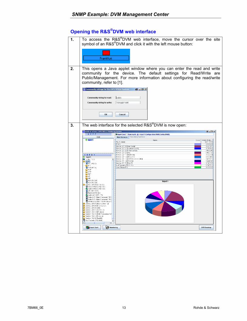
Opening the R&S®DVM web interface 1. To access the R&S®DVM web interface, move the cursor over the site
symbol of an R&S®DVM and click it with the left mouse button:
2. This opens a Java applet window where you can enter the read and write community for the device. The default settings for Read/Write are Public/Management. For more information about configuring the read/write community, refer to [1].
3. The web interface for the selected R&S®DVM is now open:

SNMP Example: DVM Management Center
7BM66_0E 14 Rohde & Schwarz
Configuring the alerting function 1. Open the "Alert View" tab:
2. Click "Config Mail Alert".
3. In the new window, define how errors will be alerted:
4. Close the window to activate the mail alerting function.
5. The e-mail notifications are formatted as follows:
Subject: "DVM mail alert" + IP address of the R&S®DVM with errors
Body: “IP address, site name, and type of error for the R&S®DVM with errors“

SNMP Example: DVM Management Center
7BM66_0E 15 Rohde & Schwarz
8 Source Code Documentation The application was implemented using the Microsoft Studio .NET 2005 development environment. The separate source code archive contains the entire project solution for Studio .NET 2005.
Introductory remarks regarding .NET The common language runtime (CLR) forms the basis of the .NET technology. The CLR is the runtime environment for various high-level languages adapted to .NET.
This virtual machine – which is another term for the runtime environment – runs the standardized intermediate code CIL (common intermediate language). In practice, this means that compilation directly into the machine code does not occur during the development process. Instead, an intermediate code is generated at the end of the development process.
Figure 6: .NET Concept
In addition, the framework class library (FCL) provides the developer with several thousand user classes.These classes allow functions such as text processing and database access, among others. With the size of software projects increasing all the time, one thing is essential: security.
The CLR efficiently ensures that unused memory is released, manages access rights to resources, and traps exceptions.

SNMP Example: DVM Management Center
7BM66_0E 16 Rohde & Schwarz
Simple network management protocol (SNMP) library SNMP++.NET v. 1.21 can be used as the SNMP stack for .NET development:
SNMP++.NET v. 1.21
Copyright (c) 2003-2006 Military Communication Institute, Zegrze, Poland Author: Marek Malowidzki
This software is based on SNMP++ from Jochen Katz, Frank Fock, which is in turn based on SNMP++2.6 from Hewlett Packard:
Copyright (c) 2001-2003 Jochen Katz, Frank Fock
Copyright (c) 1996 Hewlett-Packard Company
The library consists of the following five DLLs:
• Mib.Dll
• SnmpComp.dll
• SNMPDll.dll
• TableReader.dll
• Tools.dll
For additional information regarding this library, as well as how it can be integrated into several applications, refer to Rohde & Schwarz Application Note 7BM65 "Simple Network Management Protocol – Remote Controlling for Monitoring Devices".
Class overview The solution includes the following classes, organized by function:
Figure 7: Class overview

SNMP Example: DVM Management Center
7BM66_0E 17 Rohde & Schwarz
Functionally related classes were assigned a common name space.
DVM_Management_Center.Forms
• About.cs: Help window with contact address.
• ConfigMap.cs: Configuration window for the map graphic.
• ConfigSite.cs: Configuration window for the managed R&S®DVMs.
• MailAlert.cs: Configuration window for managing the e-mail
notification function.
• Main.cs: Main window of the application.
• SetPosition.cs: Window for positioning the R&S®DVMs on the map.
• RegExpressions.cs: Regular expressions class for checking entries
in formulas for validity.
DVM_Management_Center.Objects
• DVM_Object.cs: Class representing the functions and attributes of
an R&S®DVM.
• MAP_Object.cs: Class that manages the map and the objects it
contains.
DVM_Management_Center.SNMP
• DVM_AppFuncs.cs: Contains functions that return values that are
read out via SNMP in a format appropriate for the application.
• DVM_Basics.cs: Contains individual R&S®DVM-specific SNMP
polls.
• SNMP_Basics.cs: Serves as the interface to the SNMP library.
• SNMP_Helper.cs: Functions for converting the returned SNMP
values.

SNMP Example: DVM Management Center
7BM66_0E 18 Rohde & Schwarz
DVM_Management_Center.FileIO
• File_IO.cs: Functions for write and read access to text files.
• Xml_Serializer.cs: Used to create or read XML files.
DVM_Management_Center.Mail
• AlertSettings.cs: Stores the configuration settings for e-mail
notifications.
• SendAlert.cs: Class that generates a specific notification e-mail
within the application.
• SendMail.cs: General class for sending e-mails.
Description of the core functionality Within the main window (Main.cs), a timer initiates the polling of the managed R&S®DVMs every 7 seconds. The class DVM_AppFuncs.cs is then accessed to poll the following information:
• Pro Controller:
Site name and analyzer MAC addresses
• For every input on every analyzer:
Input name, input type, input configuration, folder name, and AnalyzerPort bit field
The polled values are then assigned to an instance of DVM_Object.cs and interpreted. Every DVM object contains all management information, as well as a TreeView node for displaying the site tree and a label/text component of the map display. Each time a new R&S®DVM is added in the GUI, a new DVM object is also created. The management information (e.g. site name, IP address, etc) is stored in an XML file by means of the XML_Serializer.cs class.
As described in the introductory chapters, it is possible to initiate an e-mail notification based on the polling results. The SendMail.cs class sends these notifications via simple mail transfer protocol. Derived from SendMail.cs, the SendAlert.cs class functions as an interface to the application.

SNMP Example: DVM Management Center
7BM66_0E 19 Rohde & Schwarz
9 References [1] Gsoedl, Harald (2007). Application Note 7BM65. Simple Network
Management Protocol. Remote Controlling for Monitoring Devices. Munich: Rohde & Schwarz GmbH & Co. KG website: http://www.rohde-schwarz.com.
10 Additional Information Our Application Notes are regularly revised and updated. Check for any changes at http://www.rohde-schwarz.com.
Please send any comments or suggestions about this Application Note to

SNMP Example: DVM Management Center
7BM66_0E 20 Rohde & Schwarz
11 Ordering Information
ROHDE & SCHWARZ GmbH & Co. KG . Mühldorfstraße 15 . D-81671 Munich. Postfach 80 14 69 . D-81614 München . Tel (089) 4129 -0 . Fax (089) 4129 - 13777 . Internet: http://www.rohde-schwarz.com
This application note and the supplied programs may only be used subject to the conditions of use set forth in the download area of the Rohde & Schwarz website.