Embed Size (px)
Citation preview

1
SmokeShield Fabric Fire and Smoke
Installation Manual

Section 1 – Table of Contents
2
Section 2 - Safety Check List 3
Section 3 - Freight Receiving 4
Section 4 - Pre-Installation 5
Section 5 - Torque Specifications 6
Section 6 - Hardware 7
Section 7 - Installation 9
Face of Wall (FOW) Installation 9
Between Jambs Under Lintel (BJUL) Installation 23
Slip Joint & Saddle Mounting 31
Section 8 - Maintenance Schedule 37
Section 9 - Air Leakage Data 39

Section 2 - Safety Check List
3
Safety Check List
Rolling doors are large, movable objects. They move with the help of electric motors or manual operators (chain, crank, push up, etc), and most have springs under high tension. These items and their components can cause injury. In order to avoid injury to yourself and others, please follow the instructions in this manual.
Review the potential hazards and preventative measures listed below:
Table 2.1 - Potential Hazards and Preventative Measures
Potential Hazard Preventative Measure
Pinned or crushed by closing door.
Keep yourself and others clear of opening while door is in motion.
Do not allow children to play near or operate door.
Do not operate if door becomes jammed or broken.
Struck by adjusting
wheel bar while applying spring
turns.
Be sure bar is adequate in strength and long enough to allow installer to apply the necessary torque.
Make sure bar is fully seated into the adjusting wheel slot before applying pressure.
Use two bars while applying turns to the adjusting wheel.
Electrical shock.
Make sure electrical operator is properly grounded.
Turn off source power completely prior to servicing the motor.
Make sure wires are clear of any moving or potentially moving parts.
Avoid pinching wires when installing the motor cover.
Pinched by moving
components.
Make sure the motor is turned off and unplugged before working with moving parts such as roller chain and sprockets, drop-out mechanisms, adjusting wheels, etc.
Locate the possible pinch-points of the unit (Drive chain, coil area, bottom bar, etc.) Do not operate the door while someone is near these areas.
Check the following during installation and before leaving the job site:
1. If the unit has tension springs, be sure the proper amount of tension is applied to the torsion
springs, in order to properly counterbalance the weight of the curtain.
2. Securely fasten the tension adjusting wheel in place with the appropriate hardware provided.
3. Check that the keys and/or cotter pins have been set in place and fit properly at all sprockets or
gears.
4. Check that the setscrews in each sprocket or gear (one over the key and one offset from the key)
have been tightened properly.
5. Check all fasteners holding the unit to the building structures.
6. Check all fasteners used to assemble the components of the unit together.
7. Instruct owner or representative in the proper method of operating the door.

Section 3 –Freight Receiving
4
Freight Receiving
Upon delivery, check condition of components for damage.
If damage occurred in transit, the installation should not proceed without authorization.
If the installation proceeds, neither the carrier nor the manufacturer will assume responsibility for
replacing the damaged material.
If the installation is stopped due to damage, do the following:
1. Take pictures of the damage.
2. Do not move material from point of delivery to other premises once the damaged components are
discovered.
3. Do not unpack, if the damage is visible prior to removing packaging, until an inspection is made.
4. If the damage is found while removing contents from packaging, the packaging material must be
saved until inspection is made.
5. Container and packaging should be retained by consignee until inspection is made.
6. Have components inspected by carrier’s representative within 15 days from date of delivery.
7. Consignee must obtain a copy of the Inspection Report.
Returning damaged components:
1. Obtain permission from carrier to return.
2. Route the return shipment via the identical carrier(s) involved in the original shipment.
3. Notify the manufacturer when shipment is returned to manufacture plant.
Verify that all components have arrived. Look for the following:
1. Job construction drawings featuring different views (elevation, section, plan, etc.)
2. (2) Guide assemblies (3 x 3 tubes for between jambs applications, 3-1/2 x 1-1/2 tubes for face of
wall to create pack-off if upset is required)
3. Barrel assembly
4. Curtain assembly
5. Bottom bar angles and flat sections
6. Bracket plates
7. Shaft support bracket assemblies with rollers
8. Operator; if not attached to bracket
9. Controller with switch
10. Hood and hood supports
11. Hardware
12. Verify material/finish/color of components matches what is listed on the job construction drawings
and/or what was ordered.
If the delivery is incomplete:
1. Make note on delivery receipt.
2. Note should be verified by driver’s signature.
3. Notify carrier and manufacture

Section 4 – Pre-Installation
5
Pre-Installation
Read entire instruction manual thoroughly. The manufacturer will not be held responsible for any
charges incurred due to improperly installed components.
a. Only trained door systems technicians should perform installation, maintenance, etc.
b. Each unit comes with an individual item number. If the job contains multiple units, be sure to
locate all the components for each item and separate each.
Do not interchange parts from one door to another.
c. Find the job construction drawings for the unit being installed and check the dimensions of the
opening against those on the drawings. See Figure 4.1 below.
d. If the opening dimensions differ from those on the drawings, do not proceed, check with
distributor/manufacturer to be sure the correct door is being installed.
e. Check the jambs of the opening for plumb. Check the head/lintel and floor for level.
Work Area:
a. The key to a smooth installation is a clean and well-prepared work environment. Once the
components have been inspected and the job construction drawings have been reviewed; lay out
the components in the order of installation.
b. The opening for the door should be cleaned and inspected for rough surfaces and construction
debris.
c. Lastly the mounting hardware supplied with the door should correspond with the surface and
construction features of the opening.
d. The basic assembly sequence is as follows: fascia hood plates, shaft support brackets, guides,
barrel assembly (brackets and tube motor), curtain, bottom bar, and hood.
Figure 4.1 – Opening Dimensions and Designations
JAMB
SILL/FLOOR
LINTEL/HEADER
OPENING
HEIGHT
OPENING WIDTH

Section 5 – Torque Specifications
6
Torque Specifications
Table 5.1 – Torque Recommendations for Guide Assembly and Wall Fasteners
Bolt size/type Torque (ft lbs) a
10-32 2.5
1/4-20 6
5/16-18 25
3/8-16 20
1/2-13 Grade 5 steel bolt 75
1/2-13 Grade 8 steel bolt 107
5/8-11 Grade 8 steel bolt 212
3/4-10 Grade 8 steel bolt 376 a The recommended torque for steel bolts is based on a plated bolt that has not been lubricated.
Table 5.2 – Torque Recommendations for Solid Masonry Wall Anchors
Manufacturer/Torque (ft lbs)a
Anchor Size (nominal)
Simpson Wedge-All Hilti-Kwik Bolt 3
3/8 30 20
1/2 60 40
5/8 90 85
3/4 150 150 a Torque values for grout filled block are different, reference bolt manufacturer for these values.

Section 6 – Hardware
7
Hardware
Table 6.1 – Hardware List – Hoods (Masonry substitute in parentheses)
Hoods
#12 x 3” self drilling hex head screw (3/16 x 1-3/4” Hex Washer Head Tapcon)
1/4” flat washer
1/4" fiber washer
1/8” pop rivet
#8 sheet metal screw
Table 6.2 – Hardware List – Guides (Masonry substitute in parentheses)
Guides
1/4” flat washer (3/8 flat washer)
1/4" fiber washer (3/8 fiber washer)
1/4 x 3” self drilling hex head screw (3/8 Simpson Drop In Anchor (DIA),
3/8-16 x 2-1/2” bolt)
1/4-20 hex flange nut
1/4"-20 x 1” hex drive screw (3/8 x 5” Simpson Wedge-All)
1/4 x 1” self threading screw
Table 6.3 – Hardware List – Brackets (Masonry substitute in parentheses)
Brackets
1/4” flat washer
3/16 x 3/4” self tapping screw
3/8-16 x 1 1/4” carriage bolt
3/8-16 hex nut
3/8 flat washer
1/4-20 hex flange nut
1/4 x 1” self threading screw
1/4-20 x 5/8 phillips pan head screw
#12 x 3” self drilling hex head screw (3/8 X 3-3/4” Simpson Wedge-All)
1/4” flat washer (3/8 washer)

Section 6 – Hardware
8
Table 6.4 – Hardware List – Bottom Bar
Bottom Bar
1/4” flat washer
1/4-20 hex flange nut
1/4-20 x 3/4” Phillips pan head screw
3/16 pop rivet
1/4-20 x 5/8 PEM stud
1/4-20 weld nut
3/8-16 x 1/2” truss head screw
3/8-16 weld nut

Section 7 – Installation
9
Installation
Face of Wall (FOW) Installation
Instructions on the following pages refer to installation over gypsum wall with metal or wood studs. Masonry equivalent fasteners/quantities are listed in each section. Different guides and support brackets are required for masonry applications.

Section 7 – Installation
10
Figure 7.1 – Fascia Hood Plate attachment
EVERY 16" ON STUD CENTERS#12 X 3" SELF DRILL SCREW1/4" WASHER, 1/4" FIBER WASHEROR3/16 X 1-3/4" TAPCON1/4" WASHER, 1/4" FIBER WASHER
6 3/4 + SETBACK
OPENING WIDTH
ASSEMBLY HEIGHT
9 1/2
GUIDE FLUSH WITHJAMB UNLESSSETBACK SPECIFIED
Figure 7.2 – Fascia Hood Plate attachment – Isometric View
SMALLER FLANGE WITHSMOKE SEAL ON BOTTOM
Section 7 – Installation
11
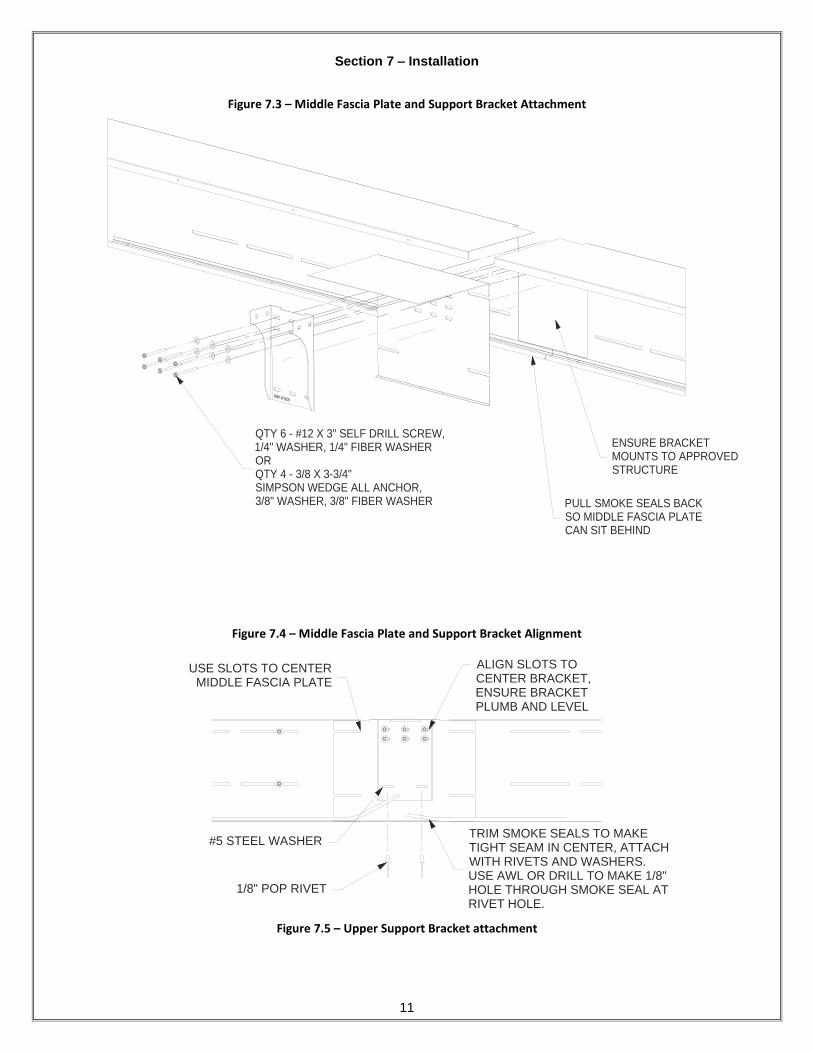
Figure 7.3 – Middle Fascia Plate and Support Bracket Attachment
ENSURE BRACKETMOUNTS TO APPROVEDSTRUCTURE
QTY 6 - #12 X 3" SELF DRILL SCREW,1/4" WASHER, 1/4" FIBER WASHERORQTY 4 - 3/8 X 3-3/4"SIMPSON WEDGE ALL ANCHOR,3/8" WASHER, 3/8" FIBER WASHER PULL SMOKE SEALS BACK
SO MIDDLE FASCIA PLATECAN SIT BEHIND
Figure 7.4 – Middle Fascia Plate and Support Bracket Alignment
Figure 7.5 – Upper Support Bracket attachment
USE SLOTS TO CENTERMIDDLE FASCIA PLATE
ALIGN SLOTS TOCENTER BRACKET,ENSURE BRACKETPLUMB AND LEVEL
1/8" POP RIVET
#5 STEEL WASHERTRIM SMOKE SEALS TO MAKETIGHT SEAM IN CENTER, ATTACHWITH RIVETS AND WASHERS.USE AWL OR DRILL TO MAKE 1/8"HOLE THROUGH SMOKE SEAL ATRIVET HOLE.

Section 7 – Installation
12
3/8-16 X 3/4"SELF TAPPING SCREW
Figure 7.6 – Fascia Side Guide attachment
1/4 X 3" SELF DRILL SCREWOR
3/8 SIMPSON DROP IN ANCHOR3/8-16 X 2-1/2" BOLT
*SET TO 3" EMBEDMENT*
1/4" FIBER WASHER
OR
3/8" FIBER WASHER
1/4" WASHER
OR
3/8" WASHER
3"
TOP OF FASCIA HOOD
HIDDEN IN THIS VIEW
FOR CLARITY
Section 7 – Installation
13
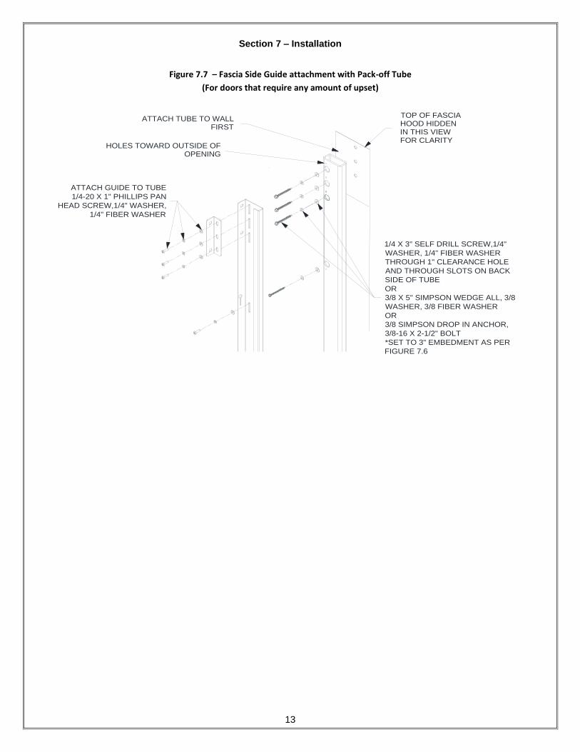
Figure 7.7 – Fascia Side Guide attachment with Pack-off Tube
(For doors that require any amount of upset)
1/4 X 3" SELF DRILL SCREW,1/4"
WASHER, 1/4" FIBER WASHER
THROUGH 1" CLEARANCE HOLE
AND THROUGH SLOTS ON BACK
SIDE OF TUBE
OR
3/8 X 5" SIMPSON WEDGE ALL, 3/8
WASHER, 3/8 FIBER WASHER
OR
3/8 SIMPSON DROP IN ANCHOR,
3/8-16 X 2-1/2" BOLT
*SET TO 3" EMBEDMENT AS PER
FIGURE 7.6
ATTACH TUBE TO WALLFIRST
ATTACH GUIDE TO TUBE
1/4-20 X 1" PHILLIPS PAN
HEAD SCREW,1/4" WASHER,
1/4" FIBER WASHER
HOLES TOWARD OUTSIDE OFOPENING
TOP OF FASCIAHOOD HIDDENIN THIS VIEWFOR CLARITY

Section 7 – Installation
14
Before installing shaft assembly in next step, ensure all electrical connections are made to
operator and controller (see operator user manual). Motor will need to be functional to
complete remaining steps.
Figure 7.8 – Shaft attachment
3/8-16 x 1 1/4CARRIAGE BOLT
3/8 WASHER
3/8-16 NUT
STRAP TO KEEPCURTAIN WRAPPEDCAN BE CUT AFTERMOTOR IS CONNECTED
CURTAIN UNWRAPSTOWARD FASCIA SIDE(END LOCKS FACE COIL SIDE)
TEMPORARILY CONNECT MOTOR CABLES TO CONTROLLER.MOTOR WILL NEED TO BE OPERATIONAL TO COMPLETEINSTALLATION. CABLES WILL NEED TO BE DISCONNECTEDLATER FOR CONDUIT TO BE PASSED THROUGH HOODPROPERLY.
BRACKET ATTACHESTO OUTSIDE FACEOF GUIDES
END LOCKS FACEOPPOSITE OF GUIDE
BOTTOM BAR ENDHARDWAREFACES INTO GUIDE
GUIDE
TOP OF FASCIA
HOOD HIDDEN
IN THIS VIEW
FOR CLARITY
Section 7 – Installation
15
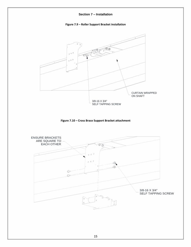
Figure 7.9 – Roller Support Bracket installation
3/8-16 X 3/4"SELF TAPPING SCREW
CURTAIN WRAPPEDON SHAFT
Figure 7.10 – Cross Brace Support Bracket attachment
3/8-16 X 3/4"SELF TAPPING SCREW
ENSURE BRACKETSARE SQUARE TO
EACH OTHER

Section 7 – Installation
16
Assemble coil side guides by aligning PEM studs with hex flange nuts attached to slots in coil
side guide that is already attached to the wall. Align slots with insert stud/nut and drop guide
down until it rests on floor. Use a nut driver to hand tighten all of the hex flange nuts after
guides are in place. Use opening at bottom of guide to insert nut driver.
Figure 7.11 – Coil Side Guide detail
1/4-20 HEX FLANGE NUTAND 1/4 FIBER WASHERONLY 1 - 2 TURNS ON STUDTO ALLOW ROOM FORSLOT ATTACHMENT
Figure 7.12 – Coil Side Guide attachment
COIL SIDE GUIDEWITH STUDS ON
INSIDE FLANGE SLIDEOVER KEY HOLE SLOTSON FASCIA SIDE GUIDE
TOP OF FASCIA HOODHIDDEN IN THIS VIEWFOR CLARITY

Section 7 – Installation
17
Figure 7.13 – Guide gap
ENSURE MINIMUM1/4" GUIDE GAP.
GENTLY PRY WITH FLATPRY-BAR IF NECESSARY
1/4" MIN
3/8" MAX
TOP OF FASCIA HOODHIDDEN IN THIS VIEWFOR CLARITY
Figure 7.14 – Cross Brace attachment
(Curtain not shown for clarity)
1/4-20 X 1 SELF THREADINGPHL SCREW AND 1/4 WASHERTHREAD INTO BRACKET
1/4-20FLANGE NUT
1/4-20 STUDSON BRACKET

Section 7 – Installation
18
Figure 7.15 – Cross Brace assembled isometric views
(Shaft and Curtain removed and top of fascia hood hidden for clarity)
CURTAIN WILL TRAVELOVER CROSS BRACEAND INTO GUIDES

Section 7 – Installation
19
Lower curtain into guides and assemble bottom bar outer angles to bottom of curtain. Curtain
may require some assistance to drop without the weight of the bottom bar angles.
Figure 7.16 – Single Bottom Bar Outer Angle attachment (Door less than 11’ 7 5/8” DBG)
3/8-16 X 1/2 PHLTRUSS HEAD
3/8-16WELD NUT
COIL SIDE
FASCIA SIDE
SMALLER DOORS MAYREQUIRE ADDITIONAL FLAT
SECTIONS FOR NECESSARYWEIGHT TO CLOSE PROPERLY

Section 7 – Installation
20
For doors larger than 11’ 7 5/8” DBG, the bottom bar will be segmented and must be assembled per
Figure 7.17 and
Figure 7.18.
Figure 7.17 – Bottom Bar Outer Angle Assemblies
3/16 RIVET
Figure 7.18 – Segmented Bottom Bar Outer Angle attachment – Larger Doors
(Guides not shown for clarity)
1/4-20 WELD NUT
1/4 WASHER
3/8-16 X 1/2 PHLTRUSS HEAD
3/18-16WELD NUT
1/4-20 X 3/4" PHL
PAN HEAD
COIL SIDE
USE CLAMP TOHOLD ANGLES TOGETHER FORASSEMBLY OF CENTERFASTENERS
CURTAIN
FASCIA SIDE
Section 7 – Installation
21
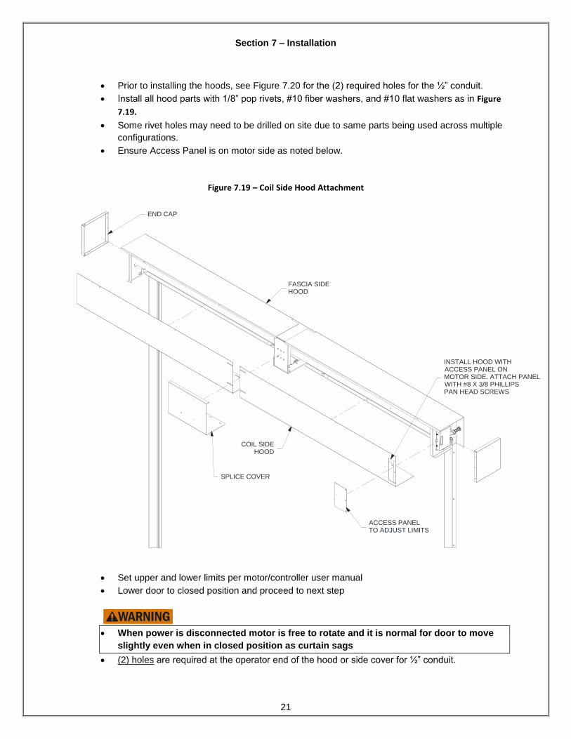
Prior to installing the hoods, see Figure 7.20 for the (2) required holes for the ½” conduit.
Install all hood parts with 1/8” pop rivets, #10 fiber washers, and #10 flat washers as in Figure
7.19.
Some rivet holes may need to be drilled on site due to same parts being used across multiple
configurations.
Ensure Access Panel is on motor side as noted below.
Figure 7.19 – Coil Side Hood Attachment
INSTALL HOOD WITHACCESS PANEL ONMOTOR SIDE. ATTACH PANELWITH #8 X 3/8 PHILLIPSPAN HEAD SCREWS
SPLICE COVER
END CAP
COIL SIDEHOOD
FASCIA SIDEHOOD
ACCESS PANELTO ADJUST LIMITS
Set upper and lower limits per motor/controller user manual
Lower door to closed position and proceed to next step
When power is disconnected motor is free to rotate and it is normal for door to move
slightly even when in closed position as curtain sags
(2) holes are required at the operator end of the hood or side cover for ½” conduit.

Section 7 – Installation
22
See the details below for acceptable hole locations in the hood parts.
Figure 7.20 – Conduit connection and End Cap installation
ACCESS PANEL
FOR LIMITS
CONNECT CABLES FROM
LIMIT BOX TO CONDUIT
CONNECTORS
(COLOR CODED)
ATTACH CONDUIT
FITTINGS TO HOOD
OR SIDE COVER
ATTACH HOOD END CAPS WITH
1/8" RIVETS (EACH SIDE)
CONDUIT TO CONTROLLER
OR JUNCTION BOX WHEN USING EXTENSION
1 7/8" ± 1/4"
(2) HOLES REQUIRED
FOR 1/2" CONDUIT
FOW COIL SIDE HOOD DETAIL
HOLES CAN BE LOCATED ON ANY FACE OF THE
COIL SIDE HOOD OTHER THAN ACCESS PANEL
END OF HOOD
1 7/8" ± 1/4"
BJUL COIL SIDE HOOD DETAIL
HOLES CAN BE LOCATED ON EITHER FACE OF THE
COIL SIDE HOOD
1 7/8" ± 1/4"
(2) HOLES REQUIRED
FOR 1/2" CONDUIT
BJUL FASCIA SIDE HOOD
DETAIL
END OF HOOD
1 3/4" MIN
5 1/2" MAX
(2) HOLES REQUIRED
FOR 1/2" CONDUIT
END OF HOOD

Section 7 – Installation
23
Between Jambs Under Lintel (BJUL) Installation
Instructions on the following pages refer to installation over gypsum wall with metal or wood studs. Masonry equivalent fasteners/quantities are listed in each section. Different guides, 3x3 tube, and support brackets are required for masonry applications.

Section 7 – Installation
24
Figure 7.21 – Hood Channel Installation
Multiple hood configuration is shown in this section. Single hood configuration is similar installation
process but one piece hoods across top and face are used.
ENSURE ADJACENT SECTIONSARE IN LINE
APPLY FIRE RATED CAULKINGALONG ENTIRE LENGTH BEFORE
ATTACHING TO LINTEL
RECTANGULAR CUTOUTFACES JAMB ON EACH SIDE
EDGE FLUSH WITH JAMB
EVERY 16" ON STUD CENTERS#12 X 3" SLF DRILL SCREW1/4" SCREW WASHER, 1/4" FIBER WASHEROR3/16" X 1-3/4" TAPCON1/4" WASHER, 1/4" FIBER WASHER
Section 7 – Installation
25
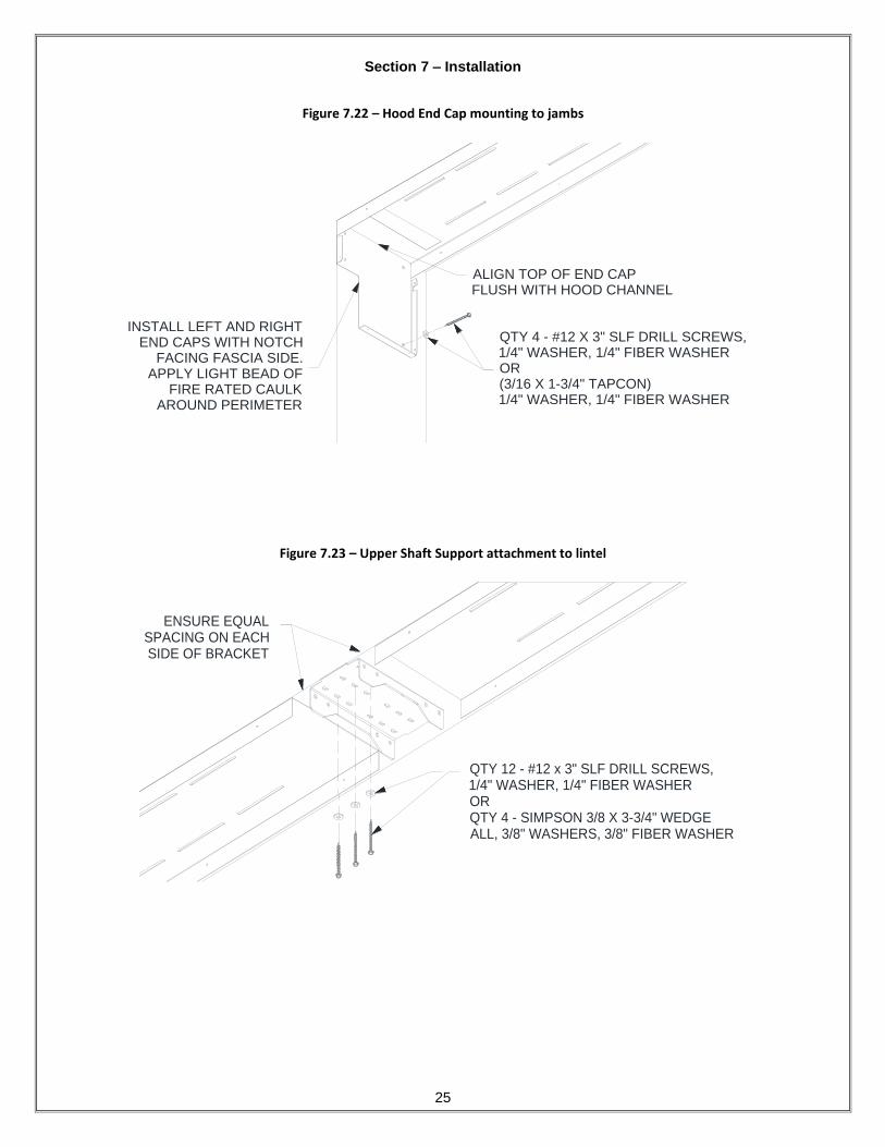
Figure 7.22 – Hood End Cap mounting to jambs
INSTALL LEFT AND RIGHTEND CAPS WITH NOTCH
FACING FASCIA SIDE.APPLY LIGHT BEAD OF
FIRE RATED CAULKAROUND PERIMETER
ALIGN TOP OF END CAPFLUSH WITH HOOD CHANNEL
QTY 4 - #12 X 3" SLF DRILL SCREWS,1/4" WASHER, 1/4" FIBER WASHEROR(3/16 X 1-3/4" TAPCON)1/4" WASHER, 1/4" FIBER WASHER
Figure 7.23 – Upper Shaft Support attachment to lintel
QTY 12 - #12 x 3" SLF DRILL SCREWS,1/4" WASHER, 1/4" FIBER WASHERORQTY 4 - SIMPSON 3/8 X 3-3/4" WEDGEALL, 3/8" WASHERS, 3/8" FIBER WASHER
ENSURE EQUALSPACING ON EACHSIDE OF BRACKET

Section 7 – Installation
26
Figure 7.24 – Upper Shaft Support attachment to lintel (bottom view)
BRACKET EDGE IN LINEWITH HOOD CHANNEL ONEACH SIDE
ENSURE EQUAL SPACINGON EACH SIDE OF BRACKET
6 SCREWS PER SIDEUSE SLOTS THAT
ALIGN WITH STUDS(2 PER SIDE MASONRY)
STUD LOCATIONWILL VARY
Figure 7.25 – Front Shaft Support attachment to Upper Shaft Support
3/8-16 X 3/4"SELF TAPPING SCREW
Section 7 – Installation
27
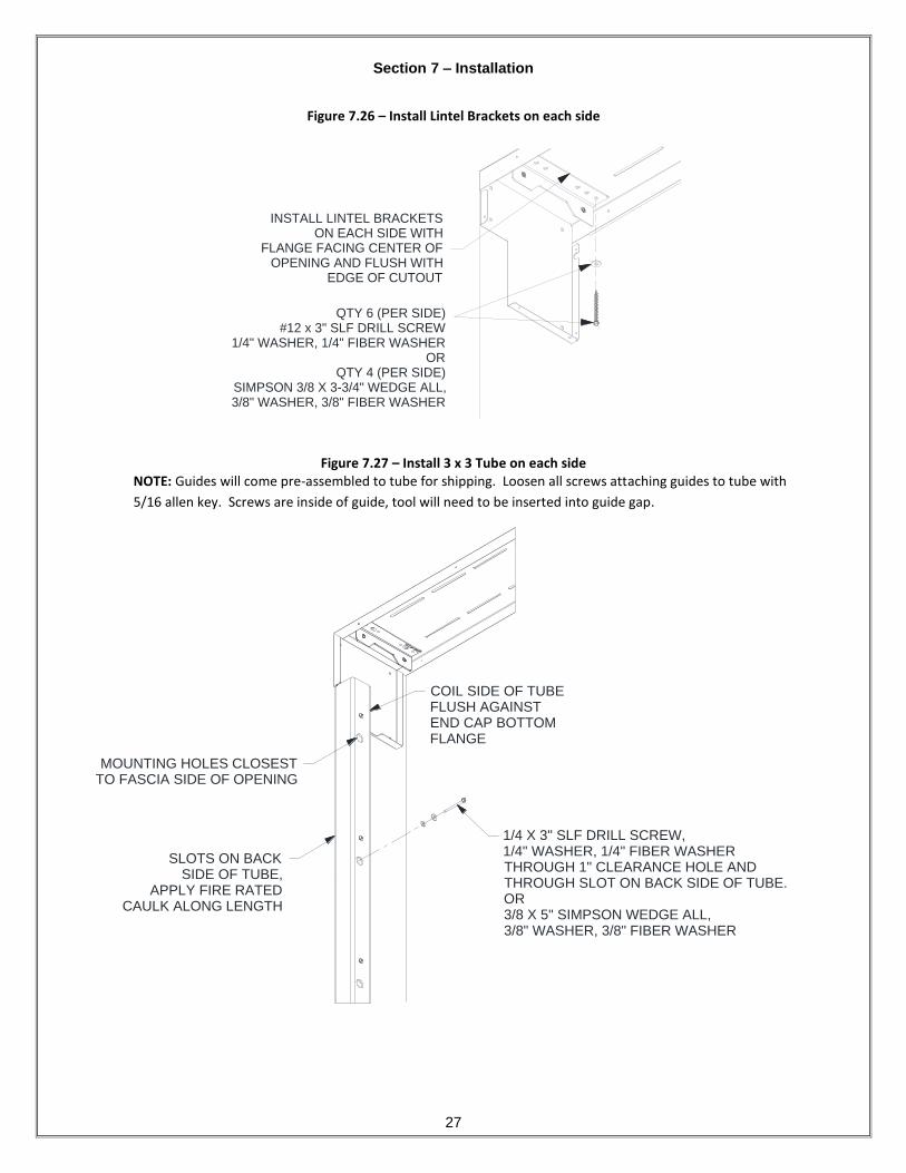
Figure 7.26 – Install Lintel Brackets on each side
INSTALL LINTEL BRACKETSON EACH SIDE WITH
FLANGE FACING CENTER OFOPENING AND FLUSH WITH
EDGE OF CUTOUT
QTY 6 (PER SIDE)#12 x 3" SLF DRILL SCREW
1/4" WASHER, 1/4" FIBER WASHEROR
QTY 4 (PER SIDE)SIMPSON 3/8 X 3-3/4" WEDGE ALL,3/8" WASHER, 3/8" FIBER WASHER
Figure 7.27 – Install 3 x 3 Tube on each side NOTE: Guides will come pre-assembled to tube for shipping. Loosen all screws attaching guides to tube with
5/16 allen key. Screws are inside of guide, tool will need to be inserted into guide gap.
1/4 X 3" SLF DRILL SCREW,1/4" WASHER, 1/4" FIBER WASHERTHROUGH 1" CLEARANCE HOLE ANDTHROUGH SLOT ON BACK SIDE OF TUBE.OR3/8 X 5" SIMPSON WEDGE ALL,3/8" WASHER, 3/8" FIBER WASHER
MOUNTING HOLES CLOSESTTO FASCIA SIDE OF OPENING
SLOTS ON BACKSIDE OF TUBE,
APPLY FIRE RATEDCAULK ALONG LENGTH
COIL SIDE OF TUBEFLUSH AGAINSTEND CAP BOTTOMFLANGE

Section 7 – Installation
28
Before installing shaft assembly in next step, ensure all electrical connections are
made to operator and controller (see operator user manual). Motor will need to be
functional to complete remaining steps.
Figure 7.25 – Shaft Installation
(Curtain not shown for clarity)
BRACKETS FLUSHWITH 3 X 3 TUBE
LOWER BRACKET FLANGEFLUSH WITH COIL
SIDE OF TUBE
QTY 2 (EACH END)3/8-16 X 3/4" BOLT
3/8" WASHER

Section 7 – Installation
29
Figure 7.26 – Guide installation
Install guides onto tube by sliding key slots over 1/4-20 allen head screws and fiber washers
(fiber washer location is not critical).
Note: Ensure minimum 1/4” and maximum 3/8” guide gap when assembly completed. Use
pry bar to gently spread guides apart if necessary.
FASCIA SIDE GUIDEHAS NOTCH ON TOP
SLIDE GUIDE KEYHOLESLOTS OVER SCREWS
ON 3X3 TUBE. TIGHTEN SCREW WITH
ALLEN KEY AFTERBOTH GUIDES INSTALLED
1/4-20 x 1" ALLEN HEADSCREW AND 1/4" FIBERWASHER
Section 7 – Installation
30
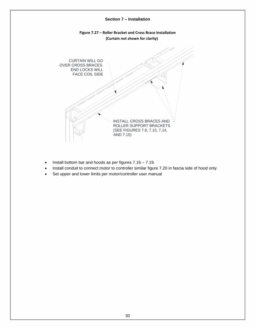
Figure 7.27 – Roller Bracket and Cross Brace Installation
(Curtain not shown for clarity)
INSTALL CROSS BRACES ANDROLLER SUPPORT BRACKETS(SEE FIGURES 7.9, 7.10, 7.14,AND 7.15)
CURTAIN WILL GOOVER CROSS BRACES.
END LOCKS WILLFACE COIL SIDE
Install bottom bar and hoods as per figures 7.16 – 7.19.
Install conduit to connect motor to controller similar figure 7.20 in fascia side of hood only.
Set upper and lower limits per motor/controller user manual
Section 7 – Installation
31
Slip Joint & Saddle Mounting

Section 7 – Installation
32
1. Measure the “Opening Width”, the distance between jambs. Compare with the job construction
drawings provided.
If this distance is not equal to the job construction drawing dimension, do not proceed!! Be sure
the correct unit is being installed. Contact the project manager.
2. The tubes are usually supplied with the inner and outer guides already attached, and can usually
be installed as one unit. For larger units, installing the tubes with the guides attached may prove
difficult. The tubes may need to be installed without the inner and outer angles attached. If you
feel this is the case, remove the inner and outer angles at this time.
3. Determine where the fascia of the door will be located with respect to the header/lintel (if one
exists) and the jamb.
4. If a header/lintel exists, see the elevation view of the job construction drawings to determine if the
door is to be placed against the header. If so, project a plumb line from the header to the floor.
Mark the floor at this location.
5. If a header/lintel does not exist, or if the door is not going to be placed against the header/lintel,
contact the project manager to determine where the door will be located. Mark the floor at this
location.
6. Locate the Saddles (brackets used to constrain the tube at the bottom). There are two types of
saddles: standard saddles and inverted saddles. Both utilize the same steps for installation. The
difference is the mounting flange. Fire doors come with inverted saddles for mounting at the
bottom of the tube.
Figure 7.43 – Tube Saddles Figure 7.44 – Tube Saddle Hole location
REGULAR SADDLE INVERTED SADDLE(MOST COMMON)
MARK ON
FLOOR PLUMB
WITH HEADER
MARK HOLES
FOR SADDLE
THROW OF SLIDE BOLT
7. Use the mark placed on the floor in the previous steps, to locate where the saddle will be and
mark the hole locations by placing the saddle on the floor. See Figure 7.44.
8. Double check the width dimensions provided on the job construction drawings, then drill holes for
the saddle fasteners.
9. Install saddles using the provided hardware.
10. Fire door guides mounting to tubes, require the use of a slip joint. There are (3) mounting styles
for slip joints, as detailed in Figures 7.45, 7.46 and 7.47. Refer to the job information to
determine the correct mounting style for the unit. Locate the Slip Joint Mounting Member(s).
11. Use the job information and the marks made in the previous steps to determine the correct Slip
Joint Mounting Member location. Install using the provided hardware. Use only enough

Section 7 – Installation
33
fasteners to hold the Mounting Members securely in place (2), as they will be removed in a later
step.
12. Determine the required tube length. Refer to Figures 7.45, 7.46 and 7.47, depending on which
configuration you are installing.
a. Measure from the “Floor to Slip Joint Mounting Member” as shown in the corresponding
figure below. Record this measurement.
b. To allow for heat expansion, the steel tube will need to be cut short. To determine the
required “Expansion Allowance”, round the measurement taken in the previous step up to the
nearest foot increment. Multiply the rounded value by 1/8 in/ft. Refer to the table below for
examples:
Table 7.1 – Slip Joint Expansion Allowances
Floor to slip
joint mounting
member (ft)
9 10 11 12 13 14 15 16 17 18 19 20
Expansion
Allowance (in) 1 1/8 1 1/4 1 3/8 1 1/2 1 5/8 1 3/4 1 7/8 2 2 1/8 2 1/4 2 3/8 2 1/2
c. Calculate the Tube Length:
Tube Length = “Floor to Slip Joint Mounting Member” – “Expansion Allowance”
d. Cut the tubes to the calculated “Tube Length”. Make sure you cut the excess tubing from the
top. Otherwise you will cut off necessary mounting holes and/or notches.
Note: If regular saddles are provided, the tube length will have to be adjusted because the tube will
not sit on the saddle flanges instead of the floor. Subtract the thickness of the flanges from the tube
length.
13. Remove the Slip Joint Mounting Member(s). Place the Slip Joint Mounting Members in the tops
of the tubes.
14. Orient the tubes (ensure the guides, mounting holes or notches are facing the correct direction.)
Place the bottom of the tube over the saddle. Stand the tube upright and reattach the slip joint
mounting member using the previously drilled/marked holes to locate. Use all provided fasteners
at this stage. Check that installed tube is plumb.
15. If you removed the inner and outer angles in Step 2, reinstall them at this point.

Section 7 – Installation
34
Figure 7.45 – Slip Joint - Between Floor and Ceiling Mounting Assembly
FASTENERS AT FLOOR
FLOOR (EXISTING)
5 MIN.
EMBEDMENT
FASTENERS
AT CEILING
1/8"/ft. OF HEIGHT
FOR EXPANSION
TUBE LENGTH
(CUT TO LENGTH
INFIELD AS REQ'D)
FLOOR MOUNTING
TUBE SADDLE
FLOOR TO
SLIP JOINT
MOUNTING
MEMBER
Section 7 – Installation
35
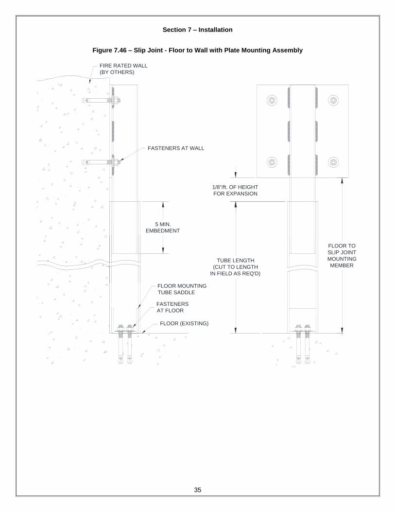
Figure 7.46 – Slip Joint - Floor to Wall with Plate Mounting Assembly
TUBE LENGTH
(CUT TO LENGTH
IN FIELD AS REQ'D)
1/8"/ft. OF HEIGHT
FOR EXPANSION
FASTENERS
AT FLOOR
FLOOR (EXISTING)
5 MIN.
EMBEDMENT
FIRE RATED WALL
(BY OTHERS)
FASTENERS AT WALL
FLOOR MOUNTING
TUBE SADDLE
FLOOR TO
SLIP JOINT
MOUNTING
MEMBER
Section 7 – Installation
36
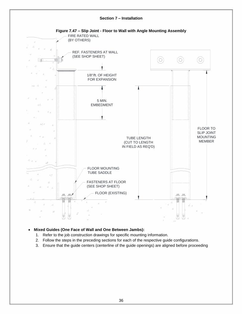
Figure 7.47 – Slip Joint - Floor to Wall with Angle Mounting Assembly
FASTENERS AT FLOOR
(SEE SHOP SHEET)
FLOOR (EXISTING)
1/8"/ft. OF HEIGHT
FOR EXPANSION
5 MIN.
EMBEDMENT
FIRE RATED WALL
(BY OTHERS)
TUBE LENGTH
(CUT TO LENGTH
IN FIELD AS REQ'D)
REF. FASTENERS AT WALL
(SEE SHOP SHEET)
FLOOR MOUNTING
TUBE SADDLE
FLOOR TO
SLIP JOINT
MOUNTING
MEMBER
Mixed Guides (One Face of Wall and One Between Jambs):
1. Refer to the job construction drawings for specific mounting information.
2. Follow the steps in the preceding sections for each of the respective guide configurations.
3. Ensure that the guide centers (centerline of the guide openings) are aligned before proceeding

Section 8 – Maintenance Schedule
37
Maintenance Schedule
Note: If any of the following problems exist, do not operate the door until repaired.
Component What to look for and how often the components must be inspected:
Weekly Monthly Quarterly What to do if problem exists:
Curtain & Bottom Bar
Are any curtain components damaged (slats, endlocks, etc.)?
X
Contact Service about replacing damaged parts.
Is bottom bar damaged? X
Contact Service about replacing damaged parts.
Are bottom bar fasteners in place and properly tightened?
X
Fasteners must be inspected/replaced and properly tightened.
Are fasteners attaching curtain to the barrel in place and properly tightened?
X
Fasteners must be inspected/replaced and properly tightened.
Do you notice any hang-ups, jamming or other problems preventing the door from moving smoothly throughout the
opening?
X
Check for external issues, if none exist, contact Service.
Do you notice any odd or excessive noise when the door is operated?
X
Check for external issues, if none exist, contact Service.
Brackets
Are brackets plumb and perpendicular with wall?
X Contact Service.
Are bracket fasteners in place and properly tightened?
X Fasteners must be inspected/replaced and
properly tightened.
Do you notice signs of excessive wear on the bearings (i.e. binding,
excessive noise, etc.)?
X
If there is a grease fitting, apply grease, if not, contact Service.
Guides
Are wall fasteners in place and properly tightened?
X
Fasteners must be inspected/replaced and properly tightened.
Are guide assembly fasteners in place and properly tightened?
X
Fasteners must be inspected/replaced and properly tightened.
Is guide gap dimension correct?
X
Guide gap must be between 1/4” and 3/8”, adjust if necessary.
Are any of the guide parts bent or damaged?
X
Contact Service.
Hood and Fascia
Is hood/fascia dented or damaged?
X Remove hood/fascia. Repair if possible. If
not leave hood/fascia off and contact Service.
Is curtain rubbing against the hood/fascia?
X
Hood/fascia may have been damaged. Contact Service.
Is hood/fascia level?
X Check fasteners, they may be loose or missing. Replace as soon as possible.
Are guide assembly fasteners in place and properly tightened?
X
Fasteners must be inspected/replaced and properly tightened.
Is hood support level?
X Check fasteners, they may be loose or missing. Replace as soon as possible.
Door operation Does the door require excessive force
to open? X
Check for hang-ups or obstructions. Ensure spring tension is set correctly.
Contact Service.

Section 8 – Maintenance Schedule
38
Component What to look for and how often the components must be inspected:
Weekly Monthly Quarterly What to do if problem exists:
Motor Operator
Are the fasteners attaching the motor-to-the mounting bracket secure?
X Fasteners must be inspected/replaced and
properly tightened. Contact Service for replacement hardware.
Is the door stopping correctly at the open and closed (as soon as the
bottom bar contacts the floor) positions?
X
Limits may have to be adjusted in the motor operator. Refer to the operator owner’s
manual or contact Service.
Is the operator functioning normally?
X
Refer to the Operator Troubleshooting Table on the following page to diagnose the
problem.
Operator Troubleshooting:
Note: If you suspect you are having an issue with your operator, use the following table to determine the potential causes. If the provided solution does not eliminate the issue, or the table does not address your particular problem, contact the Service Department.
Component Problem Potential Cause Solution
Motor Operator
Motor Operator does not run when OPEN or CLOSE button
is pushed
The circuit breaker may be flipped or fuse blown.
Reset breaker or replace fuse. Contact Service if replacement fuse is needed.
The thermal overload may be tripped. Reset thermal overload.
Motor operator runs but the door does not move
Tube motor internal gearing might be damaged.
Contact Service for repair parts. Hoods and shaft will need to be removed to
replace tube motor.
Motor hums but does not run
Door or drive chain may be jamming. Check for hang-ups or obstructions. Try to operate manually. If issue persists,
contact Service.
Brake does not release. Check power to brake solenoid.
Open motor winding. Check that all connections are secure.
Motor operator runs in wrong direction and limits do not
function Polarity is reversed. Interchange any 2 power leads to unit.
Door drifts when motor shuts off
Brake may be improperly adjusted or broken.
Contact Service for repair parts. Hoods and shaft will need to be removed to replace tube motor (brake is internal).
Motor operator does not shut off at full OPEN or at full
CLOSE position
Limits may need adjustment. Refer to the operator owner’s manual to
readjust limits.
Limit switch may be defective. Contact Service.
Limit nut retainer not engaging slots in limit nuts.
Be sure retainer is securely engaged in slots of both limit nuts.
Limit nuts binding on screw threads, allowing them to jump position on
retainer.
Lube screw thread. Check that limit nuts turn freely.

Section 9 – Air Leakage Data
39
Air Leakage Data
Please refer to the following table for specific leakage rates:
Table 9.1 – Air Leakage Data with Artificial Bottom Seal
TEST PRESSURE
(inches of WC)
SILL CONDITIONS** AIR TEMPERATURE DOOR ASSEMBLY LEAKAGE*
(cfm/ft2)
0.1 A Ambient 1.72 <3
0.2 A Ambient 2.84 <3
0.3 A Ambient 3.69 >3
0.1 A Elevated 1.98 <3
0.2 A Elevated 2.93 <3
0.3 A Elevated 3.83 >3
Table 9.2 – Air Leakage Data without Artificial Bottom Seal
TEST PRESSURE
(inches of WC)
SILL CONDITIONS** AIR TEMPERATURE DOOR ASSEMBLY LEAKAGE*
(cfm/ft2)
0.1 B Ambient 2.21 <3
0.2 B Ambient 4.68 >3
0.3 B Ambient ++ >3
0.1 B Elevated 1.92 <3
0.2 B Elevated 4.35 >3
0.3 B Elevated ++ >3
* Maximum Air Leakage Rate allowed is 3 cfm/ft2 at 0.1 inches of WC (water column).
**Sill Condition A – Assembly tested with bottom of door and frame assembly artificially sealed as allowed
by UL 1784 and NFPA 105. Sill Condition B – Assembly tested without artificial bottom seal.