Embed Size (px)
Citation preview

Certificate
This is to certify that the work presented in this project report is a bonafied work of
SUBHAM KUMAR MODI a student of 7th semester B.Tech (mechanical engineering) of
“Academy of Technology” Hooghly, West Bengal has undergone a indutrial training from
01.07.2016 to 30.07.2016 at THE POWER PLANT and THE SINTER PLANT of TATA METALIKS
LIMITED, vill: Mahespur, PO: Samraipur, PS: Kharagpur, Local: Paschim Medinapur, 721301,
WEST BENGAL, INDIA
………………………………….. …………………………………
Mr. A. BANERJEE Mr. D. BANERJEE
(HOD POWER HOUSE) (HOD SINTER PLANT OPERATION)
…………………………………… ……………………………………
Mr. E. A. KUMAR Dr. S. SAHAI
(HOD SINTER PLANT MAINTAINANCE) (HEAD PLANT HR)
Content
I. CERTIFICATE
II. CONTENT
III. ABSTRACT
IV. ACKNOWLEDGEMENT
1) COMPANY PROFILE
2) INTRODUCTION
3) POWER PLANT
A. OVERVIEW
B. THERMODYNAMICAL CONCEPT OF POWER PLANT
C. STEAM AND WATER CYCLE
D. BOILER AND ITS ASSOCIATED COMPONENTS
E. TURBINE AND ITS COMPONENTS
F. CONDENSOR
G. DEAERATOR
H. FANS USED IN POWER PLANT
I. CHIMNEY
J. DM PLANT
4) SINTER PLANT
A. OVERVIEW
B. SINTER AND ITS PROCESS
C. COMMON UNITS OF SINTER PLANT
D. SINTER MACHINE
5) CONCLUSION
6) REFERENCES

Abstract
Refining of iron ore is the most important need of the era, since everywhere various iron products
are used in different forms and structure. Hence the 1st most primary form that we get after
refining the ore is pig iron.
Pig iron is the intermediate product of smelting iron ore. It is
the molten iron from the blast furnace, which is a large and
cylinder-shaped furnace charged with iron ore, coke, and
limestone. Charcoal and anthracite have also been used as
fuel. Pig iron has a very high carbon content, typically 3.5–
4.5%, along with silica and other constituents of dross, which
makes it very brittle and not useful directly as a material
except for limited applications.
The traditional shape of the molds used for pig iron ingots was a branching structure formed
in sand, with many individual ingots at right angles to a central channel or runner,
resembling a litter of piglets being suckled by a sow. When the metal had cooled and
hardened, the smaller ingots (the pigs) were simply broken from the runner (the sow),
hence the name pig iron. As pig iron is intended for remelting, the uneven size of the ingots
and the inclusion of small amounts of sand caused only insignificant problems considering
the ease of casting and handling them.
Sinter plants agglomerate iron ore fines (dust) with other fine materials at high
temperature, to create a product that can be used in a blast furnace. The final product,
a sinter, is a small, irregular nodule of iron mixed with small amounts of other minerals.
Sintering is the process of compacting and forming a solid mass of material by heat and/or pressure without melting it to the point of liquefaction. Sintering happens naturally in mineral deposits or as a manufacturing process used with metals, ceramics, plastics, and other materials. The atoms in the materials diffuse across the boundaries of the particles, fusing the particles together and creating one solid piece.
Acknowledgement
It is to acknowledge that I, a student of mechanical engineering from Academy of
Technology, Hooghly, West Bengal, present this report on the sinter plant and power plant
that runs on blast furnace gas as fuel to support the two blast furnace (MBF I-II) used to
extract the pig iron. This work is based on the industrial training program conducted under
the supervision of various intellectual engineers and officers associated with TATA
METALIKS, during the period of 30 days, i.e 01.07.16 to 30.07.16
With due respect I would like to thank Mr.D.Banerjee, Mr. A.Banerjee, Mr. E.A.Kumar and
all other members associated with the project guidance. A special thanks to Mr. S.Sengupta
and Dr.S.Sahai without whose help the project would have been a abstract.
The practical exposure of the working of a power plant with fuel as blast furnace gas and the
making and use of sinter in the extraction of pig iron has helped us to understand the
academics of mechanical engineering more transparently. I also appreciate TATA group for
establishing such industries and being a pioneer in the growth and development of the
industrial and economic sector of the nation.
Subham kumar modi

Company’s profile
As one of the leading manufacturers of foundry grade pig iron in India, Tata Metaliks Limited
(TML) is committed to deliver excellence. Inspired by the rich Tata heritage, the Company
has grown from strength to strength over the last two decades since its inception in 1990.
A subsidiary of Tata Steel, TML has its manufacturing plant at Kharagpur, West Bengal, India
with an annual production capacity of 345,000 tonnes of pig iron and turnover of Rs. 12.3
billion in 2014-15. With the help of its team of experienced professionals and state-of-the-
art manufacturing facilities, TML produces one of the finest qualities of pig iron in India.
The Company has been fulfilling its vision of "Reaching Tomorrow First" by offering
innovative products to its customers worldwide. In 2012-13, Tata Metaliks introduced its
premium product Tata eFee®, the first branded pig iron that reduces energy consumption in
foundries by 5-15%. Tata Metaliks also manufactures Ductile Iron Pipes through its 100%
subsidiary company, Tata Metaliks DI Pipes Ltd. (TMDIPL). Setting industry benchmarks through quality and service, as a way forward, the Company
has set ambitious targets of manufacturing and
selling higher volumes of pig iron by increasing
the capacity of its plant. As a part of backward
integration, Tata Metaliks has set up a 4,00,000
tpa Sinter Plant to improve its productivity and
cost competitiveness. With latest capacity
expansions and improvement initiatives, the
Company is on a steady growth curve while
focussing on performance excellence.

Introduction
A blast furnace is a smelting furnace in the form of a tower into which a blast of hot
compressed air can be introduced from below. Such furnaces are used chiefly to make iron
from a mixture of iron ore, coke, and limestone. The first blast furnaces appeared in the 14th
Century and produced one ton per day. Blast furnace equipment is in continuous evolution and modern,
giant furnaces produce 13,000 tons per day. Even though equipment is improved and higher production
rates can be achieved, the processes inside the blast furnace remain the same.
Blast furnace gas (BFG) is a by-product of blast furnaces that is generated when the iron ore
is reduced with coke to metallic iron. It has a very low heating value, about 93 BTU/cubic
foot, because it consists of about 60 percent nitrogen and 18-20% carbon dioxide, which are
not flammable.
The total amount of CO and CO2 gases by volume in the BF gas at the furnace top is around
40 % to 45 % of the total gas volume. The CO/CO2 ratio can vary in a blast furnace. Higher
percentage of CO in the gas makes the BF gas more hazardous. Hence for environmental
consequences this gas is used again by the power house to run the turbine and generate
power , used for various operation in the blast furnace and the industry, reducing the
consumption of electricity from the national power grid.
While the purpose of the sinter plant is to process fine grained raw materials into a coarse
grained iron ore sinter, ready to be charged to the blast furnace. Sintering of fine particles
into a porous clinker – sinter – is necessary to improve the permeability of the burden,
making reduction easier. A high quality sinter has high reducing ability, which reduces the
intensity of blast furnace operations and reduces coke demand.

POWER PLANT
CPP (Captive Power Plant)
Overview
At Tata Metaliks Limited, the plant generates most part of the electricity it needs, through
its two power plants i.e. CPP-1 and CPP-1 . Here CPP means Captive Power Plant. There is
one power plant for one of the blast furnaces (and their supporting plants) each, only the
sinter plant runs on grid power.
A Captive Power Plant is a facility that is dedicated to providing a localised source of power
to an energy user. These are typically industrial facilities or large offices. The plants may
operate in grid parallel mode with the ability to export surplus power to the local electricity
distribution network. Alternatively they may have the ability to operate in island mode; i.e.
independently of the local electricity distribution system.
Captive power plants are a form of distributed generation, generating power close to the source of use. Distributed generation facilitates the high fuel efficiency along with minimising losses associated with the transmission of electricity from centralised power plants.
In Tata Metaliks, blast furnace gas is used as a fuel for the captive power plants. It not only reduces the cost of buying electricity from outside but also is environment-friendly as BFG(blast furnace gas) is harmful to the environment and living beings and it is burned as fuel and then emitted in the air rather than emitting it as it is.
A Captive power plant is useful as:-
1) It provides continuous power supply through self generation i.e. the plant is no more dependent on grid power to run it.
2) It makes the plant more environment-friendly as it reduces the pollution significantly
Blast furnace gas here heats the boiler which in turn generates steam and the steam is used to rotate turbines which are connected to alternators which generate 3-phase AC electricity.

FLOW DIAGRAM OF THE POWER PLANT
#2(4 Megawatt)
SD - steam Drum PS - primary superheater
SS - secondary superheater DS - De- Superheater
MSL - main steam line TG - Turbo Generator
CN - Condenser CT - cooling tower
CEP - condensate Extraction pump EJ - Ejector
BFP - Boiler Feed Pump Eco - Economiser’
DMTP - DM Transfer Pump DM - Demineralised

Thermodynamical concept of working
of a power plant
A power plant follows a combination of reheat and regenerative
modification of the Rankine cycle. In this process heat is added
to the saturated water at constant pressure to form saturated
vapour, then it is superheated at constant pressure to a higher
temperature then the steam expands isetropically in an H.P
turbine and does work on its blades as a result the pressure and
temperature of the steam fall. After this a part of the steam is
regenerated to the feed water heater and the rest is reheated
to a higher temperature isobarically. Then again it expands in
the I.P. turbine generating shaft power and simultaneously fall
in pressure and temperature. From the I.P turbine a part of the steam is again regenerated and the
rest is finally expanded in the L.P turbine. After leaving the L.P. turbine the steam is .85 dry and then
it enters the condenser where the steam forms saturated water by constant pressure heat rejection.
After the condenser the saturated water enters the boiler feed pump which pumps the water to a
higher pressure to the boiler drum.
BOILER
A boiler or steam generator is a device used to create steam by applying heat energy to water
Although the definitions are somewhat flexible, it can be said that older steam generators were
commonly termed boilers and worked at low to medium pressure (1–300 psi or 6.895–
2,068.427 kPa) but, at pressures above this, it is more usual to speak of a steam generator
There are two types of boiler namely:
i) Water tube boiler- In the water tube boiler the water is circulated through pipes in the
walls of the boiler and fire is lighted at the middle by spraying pulverized coal.
ii) Fire tube boiler- In the fire tube boiler the fire is run through tubes at the centre of
boiler and the water is circulated around the fire tubes leading to the heat transfer from
the fire to the circulating water.

WATER CYCLE IN POWER GENERATION
OF A POWER PLANT
In the water cycle of a thermal power plant the saturated water of the condenser is extracted from
the condenser using a condensate extraction pump at a stipulated temperature and pressure. The
C.E. pump, pumps this water into the deaerator to relieve the water of all gas molecules, after
preheating it in the L.P heater. The deaeration is done for safe working of the boiler feed pump,
because if air molecules are sucked into the B.F.P then it may lead to its damage or retard its
pumping efficiency. After deaeration of the water it is sucked into the Boiler Feed Pump, the B.F.P.
then pumps this water into the boiler drum through a H.P. heater and then to an economizer where
the water is finally preheated by extracting heat from the outgoing flue gas from the boiler, leading
to its final increase in its enthalpy.
Now in the boiler drum the saturated water is converted to saturated vapour by heat addition at
constant pressure by passing it through the water tubes of the boiler where there is a large increase
in the enthalpy of the fluid and the constant pressure is maintained in the boiler drum due to the
presence of mixture of the water and vapour and it is also fitted with pressure sensitive valves which
extract steam from the boiler as there is an increase in the boiler drum pressure.
STEAM CYCLE IN POWER GENERATION
OF A POWER PLANT
Saturated steam from the boiler drum is superheated at the same pressure to a temperature of
about 540deg Celsius which is the combustion temperature of coal , by passing it through the
superheated tubes of the boiler. Where there is an increase in its enthalpy. Then the steam is
directed to the high pressure turbine
where the steam expands isentropic ally
through the turbine blades making it to
rotate and here the enthalpy of the
steam is converted to mechanical energy
of the turbine shaft, this leads to a drop
in the temperature, pressure, enthalpy
of the steam. Then from the H.P turbine
a part of the steam is regenerated to the
H.P heater and the rest is reheated in
the boiler at constant pressure to a
higher temperature to obtain an increase in its enthalpy. From the reheated the steam is fed to the
Intermediate pressure turbine, where it expands isentropic ally leading to a drop in its enthalpy and
conversion into shaft power. From the I.P. turbine a part of the steam is again regenerated to the

L.P. heater and the rest is again finally expanded in the low pressure turbine for the extraction of the
remaining enthalpy of the steam and partially converting the steam into water with a quality of .85 .
Then the steam enters the condenser where it is converted to saturated water at constant pressure.
The ph of the water circulating in the cycle is constantly monitored as acidic water may damage the
equipments of the plant. Therefore the ph is always kept less than 7. Now if the ph of the water rises
so this water is discarded from the cycle by throwing out the steam. This process is known as blow
down.
ASSOCIATED COMPONENTS OF A
BOILER
Feed Water Pump:
The first step is to get a constant supply of water at high pressure into the boiler. Since the boiler is always at a high pressure. ‘Boiler feed water pump’ pumps the water at high pressure into the boiler from the ‘feed water tank’. The pump is akin to the heart in the human body.
Drum: The drum itself a large cylindrical vessel that functions as the storage and feeding point for water and the collection point for water and steam mixture. This is the largest and most important pressure part in the boiler and weighs in the range 250 Tons for 600 MW power plant.
Water Walls: Boiling takes place in the ‘Water Walls’ which are water filled tubes that form the walls of the furnace. Water Walls get the water from the ‘down comers’ which are large pipes connected to the drum. The down comers and the water wall tubes form the two legs of a water column. As the water heats up in the furnace a part of the water in the water-wall tubes becomes steam. This water steam mixture has a lower density than the water in the down comers. This density difference creates a circulation of water from the drum, through the down comers, water walls and back to the drum. Steam collects at the upper half of the drum. The steam is then sent to the next sections. The temperature in the drum, down comers and water wall is at the saturation temperature.
Economiser: Most of the sensible heat is absorbed in the Economiser. These are a set of coils made from steel tubes located in the tail end of a boiler. The hot gases leaving the boiler furnace heat the water in the coils. The water temperature is slightly less than the saturation temperature. From the economiser the water is fed to the 'drum'.
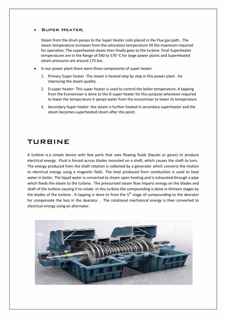
Super Heater:
Steam from the drum passes to the Super Heater coils placed in the Flue gas path.. The steam temperature increases from the saturation temperature till the maximum required for operation. The superheated steam then finally goes to the turbine. Final Superheater temperatures are in the Range of 540 to 570 °C for large power plants and SuperHeated steam pressures are around 175 bar.
In our power plant there were three components of super heater
1. Primary Super heater -The steam is heated step by step in this power plant . for improving the steam quality.
2. D-super heater- This super heater is used to control the boiler temperature. A tapping from the Economiser is done to the D-super heater for this purpose.whenever required to lower the temperature it sprays water from the economiser to lower its temperature
3. Secondary Super heater- the steam is further heated in secondary superheater and the steam becomes superheated steam after this point.
TURBINE
A turbine is a simple device with few parts that uses flowing fluids (liquids or gases) to produce
electrical energy. Fluid is forced across blades mounted on a shaft, which causes the shaft to turn.
The energy produced from the shaft rotation is collected by a generator which converts the motion
to electrical energy using a magnetic field.. The heat produced from combustion is used to heat
water in boiler. The liquid water is converted to steam upon heating and is exhausted through a pipe
which feeds the steam to the turbine. The pressurized steam flow imparts energy on the blades and
shaft of the turbine causing it to rotate. In this turbine the compounding is done in thirteen stages by
the blades of the turbine . A tapping is done to from the 5th stage of compounding to the dearator
for compensate the loss in the dearator . The rotational mechanical energy is then converted to
electrical energy using an alternator.

OIL COOLER There is an oil cooling circuit for the cooling of the turbine . the oil is used for two purposes
1. For the lubrication of the bearings and the gear boxes
2. For cooling of the turbine- the cooled oil is circulated in the front and rear side of the tubine
bearing, in the main gear box, and the front and rear bearings
The oil is circulated in the following parts of the turbine and then it feed back to the heat exchanger
where oil is cooled with the induced cool water from the cooling tower. The cooled water is then
pass through an oil filter where extra particles are removed and then it is distributed to parts of the
turbine.
Trip Circuit- There is an trip circuit for any emergengy purpose. The circuit closes the supply of the
steam from the main steam line
Condenser
A condenser is a commonly used term for a water-
cooled shell and tube heat exchanger installed on the
exhaust steam from a steam turbine in thermal power
stations. These condensers are heat exchangers which
convert steam from its gaseous to its liquid state at a
pressure below atmospheric pressure, Where cooling water
is in short supply, an air-cooled condenser is often used. An
air-cooled condenser is however, significantly more
expensive and cannot achieve as low a steam turbine
exhaust pressure (and temperature) as a water-cooled surface condenser.
Condenser- If the steam coming out from the turbine is released into the atmosphere, it will result in a huge amount of wastage of water. So the steam is condensed to water to feed it to the boiler again. Here the there are two subparts:
1) Cooling Tower: Here the steam is cooled by the means of cooling water 2) CWP: CWP or the condensed water pump is used to pump the condensed
water back to the condenser from the cooling tower.

Mechanical draught cooling tower: these uses a power driven fan motors to force or draw air
through the towers. A mechanical induced draft tower with a fan at the discharge (at the top) which
pulls the air up through tower. The fan induces hot moist air out the discharge. This produces low
entering and high exiting air velocities, reducing the possibility of recirculation in which discharged
air flows back into the air intake.
This process continues as long as the condensed water is not at a particular temperature. The condenser contains a hot-well where the hot water is stored.
CEP- CEP(Condensate extraction pump) is a pump used to circulate condensate water in the feed cycle path up to dearator a specified pressure. It is a multi-stage (8-stage) pump.
deaerator
A deaerator is a device that is widely used for the removal of oxygen and other
dissolved gases from the feed water to steam-generating boilers. In particular,
dissolved oxygen in boiler feed waters will cause serious corrosion damage in steam systems
by attaching to the walls of metal piping and other metallic equipment and
forming oxides (rust). Dissolved carbon dioxide combines with water to form carbonic
acid that causes further corrosion. Most deaerators are designed to remove oxygen down to
levels of 7 ppb by weight (0.005 cm³/L) or less as well as essentially eliminating carbon
dioxide.
There are two basic types of deaerators, the tray-type and the spray-type:
The tray-type (also called the cascade-type) includes a vertical domed deaeration
section mounted on top of a horizontal cylindrical vessel which serves as the deaerated
boiler feedwater storage tank.
The spray-type consists only of a horizontal (or vertical) cylindrical vessel which serves
as both the deaeration section and the boiler feedwater storage tank.

FANS FOR POWER PLANT
Supply air for combustion in the furnace and for evacuation of the flue gases formed from
the combustion.
Maintain balanced draft inside the furnace.
Supply air for cooling of equipments working in hot zones.
Supply air for sealing of gates, feeders & mill bearings ets.
Air used for combustion is divided into two parts.
1. Primary air:
Portion f total air sent through mill to the furnace. This air dries the pulverised coal and
transport it to the furnace for combustion.
2. Secondary air
Large portion of total air sent to furnace to supply necessary oxygen for the combustion.
Types of fan
I. Axial fan with two sub groups i. Impulse ii. Reaction
II. Radial fan or centrifugal fan (single suction or double suction).
Forced Draft (FD) Fan:
Supplies secondary air to the furnace through APF to assist in combustion.
Supply total air flow to the furnace except where an independent atmospheric P.A Fan is
used.
Provides air for sealing requirement and excess air requirement in the furnace
Axial fan-reaction type with blade pitch control is use in the pulverised fired boiler.

Induced Draft (ID) Fan:
Suck the gases out of the furnace and throw them into the stack by creating sufficient
negative pressure in the furnace (5-10mmwc) in the balanced draft units.
Located in between the ESP and chimney in the flue gas path.
Radial fans- double suction backward curved vane with inlet guide vane control and VFD is
use in all boilers.
Handles large volume of hot dust/ash laden flue gases from the furnace and all leakage
occurring in the system till the inlet of the fan.
CHIMNEY
The function of the chimney is to eject flue gas out of the plant. The height of the chimney is kept
sufficiently large so that the flue gas does not fall over the plant and also to create a higher draught
for driving the waste out of the flue gas circuit.
.

Demineralised Plant
Typical flow diagram of a DM plant
What is DM Plant? Why use DM plant?
In power plant water is known as the heart of the plant, so it is most necessary to supply salt free
water for process. The demineralization is the process of removing mineral salts from water by
using ion exchange process. The D.M water reduces the scale formation, Deposition and corrosion
of tubes. It increases the life of pipes and tubes in plant. It prevents the deposition of minerals in
turbine blades. It removes Mineral salts in the form of cations such as sodium, calcium, iron, copper
and anions such as chloride, sulphate , nitrate etc.
SOURCES OF WATER
There are 3 types of sources of water-
1. Surface water - River water,lake water, pond water ect.
2. Ground water - Bore water, well water.
3. Sea water - Sea water.
Rain water is the purist of all sources of water. since the water having unique property of absorbing
everything on the earth that is why water is called universal solution. As the rain water falls on the
earth it will be exposed with several gases present in the atmosphere, after falling on the earth
water will be flows through several salts& minerals on the earth. In this way water is getting
contaminated.
Reservoir:-Reservoir is used for water storage purpose. Water is taken from here for dm
water process work
MULTI GRADE FILTER (MGF):- It consists of vertical or horizontal pressure filters that
contain multiple layer of coarse fine sand.It reduce turbudity and TSS (<5 PPM) from water. water is
passed through multi layers of filter media consisting graded sand, pebbles and gravels layers. The
contaminants in the water are captured in the media bed and filtered water passes into the
discharge manifold at the bottom of the tanks. The next and last step is back washing, a process of
effectively removal of captured contaminants from the media bed. After back-washing the filter is
rinsed with raw water and after the required quality of water is achieved the filter is put back into
service.
Activated carbon filter- It reduces the turbidity, filters totalled dissolved solids, reduces
the smell of water and for dechorinization purpose
Strong Acid cation(H+
)- as the name suggest it absorbs the cation from the the water.
There is a resin which can catch the cations. The H+ are then regenerated by Hydrazine.
Re-H + KCl = Re-K + HCl
Strong Base anion(OH-
)- It absorbs the anions from the water. The resin absorbs the
excess anions from water
Mixed bed- mixed bed contains both H+ and OH- bed resins. If some cations or anions are not
removed it is then removed by mixed bed
Degreaser system- in this system the co2 and other gases are removed

Sinter plant
overview
Sintering plants are normally associated with the production of hot metal in blast furnaces in integrated steel pants. The process of sintering is basically a pre-treatment process step during iron making to produce charge material called sinter for the blast furnace from iron ore fines and also from metallurgical wastes (collected dusts, sludge and mill scale etc.). The sintering technology was originally developed for the purpose of using the iron the metallurgical waste of a steel plant and iron ore fines in the blast furnace. But currently the focus has changed. Now the sintering process aims to produce a high quality burden for the blast furnace. Today sinter is the main metallic burden for a large blast furnace. The Principle of sintering The principle of sintering involves the heating of iron ore fines along with flux and coke fines or coal to produce a semi-molten mass that solidifies into porous pieces of sinter with the size and strength characteristics necessary for feeding into the blast furnace. It is basically an agglomeration process achieved through combustion .
Sintering Plant - TATA METALIKS LTD.
Sinter Project approved by TML Board 31st January 2011 by CAPEX.
40.5 SQM size Linear Sinter Machine and Linear Cooler.
Consortium Partners : China metallurgical Engineering and Project Corporation (MEPC).
SINO India Metallurgical Engineering and Supply (P) LTD.
Karan Construction Company (KCC)
Site Work Started on 4th march 2011.

The Product Sinter
The product of the sintering process is called sinter and is having good following quality characteristics
1. Chemical analysis 2. Grain size distribution 3. Reducibility 4. Sinter strength
Typical properties of sinter
Item Unit Value
Fe % 56.5 to 57.5
Feo % 6.0-8.0
SiO2 % 4.0 to 5.0
Al2O3 % 1.8 to 2.5
CaO % 7.5 to 8.5
MgO % 1.6 to 2.0
Basicity (CaO/SiO2)
1.7 to 2.9
ISO Strength (+6.3mm) % >75
RDI (-3 mm) % 27-31

The Process
The process of sintering begins with the preparation of the raw materials consisting of iron ore fines, fluxes, in-plant metallurgical waste materials, fuel and return fines of the sinter plant. These materials are mixed in a rotating drum and water is added in order to reach proper agglomeration of the raw materials mix. This agglomeration is in the form of micro-pellets. These micro pallets assist in obtaining optimum permeability during the sintering process. These micro pellets are then conveyed to the sintering machine and charged. A layer of controlled size sinter (bedding) is fed to the bottom of the sinter machine grates for the protection of the grates. After this the moistened micro pellets of the raw materials mix is fed and leveled.
After the material is leveled on the sinter machine, the surface of the charged material on the sinter machine is ignited using gas or oil burners. Air is drawn through the moving bed causing the fuel to burn. Sinter machine velocity and gas flow are controlled to ensure that “burn through” (i.e. the point at which the burning fuel layer reaches the base of the strand) occurs just prior to the sinter being discharged. During the machine movement the sintering of the material bed on the grate proceeds downward. Waste gas circuit is to be fully leak proof, not allowing air from atmosphere to be sucked by the system. This results into saving of power in the waste gas circuit.

At the end of the machine the sintered material in the form of cake is discharged into the hot sinter crusher. Here the hot sinter cake is crushed to a pre-determined maximum particle size. From here the sinter is discharged onto sinter cooler which can be either straight line or circular cooler. After cooler the sinter is transferred to the screening section. In the screening section the product sinter, bedding and return fines are separated. Return fines, not suitable for downstream processing, are conveyed to a bin for recycling in the sintering process.

Common units of a sinter plant
1. Raw materials handling system
2. Crushing of fluxes and coke breeze
3. Propositioning of raw materials
4. Mixing and nodulizing
5. Charging of mix on to sintering bed
6. Ignition of charge on sinter bed
7. Sintering process along the sinter bed
8. Cooling of product sinter
9. Screening of cold sinter
10. Conveying of product sinter to BF stock house
raw materials handling systems
A belt conveyer is an iron structure to support the belt used for transporting material
generally at a very small or zero angles to the horizontal from one location to another. The
belt is supported by idlers throughout the way. The idlers are arranged in a trough on the
carrying side and flat on the bottom or return side. The driving unit move one or more
pulleys which, in turn move the belt. The whole conveyor is supported on a steel structure
known as TRANSOM, which supports and keeps the idlers in line as well as supports the
pulleys and the drive cover.
The gravity pulley is tightening the
entire belt so that there should not
be any sagging of belt in the
conveyor system of RMHS (Raw
material handling system).
Belt conveyers are used to carry
economically greater diversity of
bulk materials and for greater
distances. It can be use for material
varying in lump size, moisture
content, chemical composition and
characteristics.

Crushing house
The required material is needed of 3mm size, and
the given material supply is of variable sizes so, the
given materials should be properly crushed to the
required sizes. Each material need a different
crusher, like coke breeze needs a 4 roll crusher and
fluxes like dolomite and limestone needs hammer
mill for crushing, it’s their force withstanding quality.
In the plant there are 2 hammer roll crusher(both forward and reverse motions are
possible)and one four roll crusher
From the hoppers, the raw materials like coke breeze, dolomite and limestone travel
through conveyor belt as a medium. Coke breeze & flux (i.e. fuel and flux) belt and then
separate into F1, F2, F3 and F4 line for fuel and FL1, FL2, FL3, FL4 and FL5 for flux. The fuel
circuit goes to 4 roll crusher and the flux circuit goes to hammer mill.
FOUR ROLLER CRUSHER
Four roll crusher is used to crush coke. The product
coke breeze are then transferred to the bunkers via
conveyer belts the crossectional diagram
Specification of four roll crusher
Maker Henen qurying machine manufacturing
Model 4 P G 900*700
Feeding size 40/100
Discharge size Less than 10
Motor power 24/30
Crushing capacity Less than 18 TPH
SRL number 11105003
Roller diameter 900mm
Roller length 700mm
Upper roller gap 8-10mm
Lower roller gap 3-4mm

HAMMER ROLL CRUSHER
Hammer roll crusher is used to crush to
crush fluxes like dolomite and limestone. There
are two hammer roll crusher one for back up
purpose. The fluxes like dolomite and limestones
are crushed one by one and the size is 3mm
+80% and he send to the bunkers after screening
The specification of hammer roll crusher is
below:
Hammer crushing mill
Feeding size 40mm
Product size 3mm
Rotor speed 1104 rpm
Capacity 35 TPH
Propositioning of raw materials
This is the sector where the raw materials after crushed gets into a line, feed one above the
other. In raw feeder particles plant, there are a total of 14 hoppers,
1- 6 hoppers are for iron ore fines,7 - 8 hopper are for crushed coke breeze and the
9th,10th,11th & 13th are for the fluxes crushed dolomite, limestone alternatively. The 13th
hopper is for quick lime, which is also a kind of flux. These raw materials are layered one by
one using feeder machine. There is a separate machine used for weighing and feeding into
the conveyor belt, that machine is called weigh feeder. This weigh feeder is used to
estimate the output product in terms of tons per hour (TPH).

weigh feeder
This machine, weighs the input raw material and the output material is compressed to the required
quantity and estimated to tons per hour (TPH). This machine is connected to the main control frame
for estimating quantity of output. The techniques used are zeroing and tearing. Zeroing is making
the overall weight of the quantity of the material to zero and tearing is distributing the weight all
throughout.

Mixing and nodulizing drum
The raw materials which are feed from raw feeder
particles chamber and sent to mixing and nodulizing
drum. In this drum, the raw materials are mixed like
churning and a little moisture is added and mixed
throughout and the product is sent out through the
product belt. This mixing an nodulizing should have
proper moisture else the mixture will be damp. So,
there is a moisture detecting machine known as
“moisture probe “This detects the moisture content in
the mixture and alert the unit if the content of
moisture is either high or low.
Mixing and nodulizing
Drum diameter 2800mm
Drum length 9000mm
Inclination 0.9o
Speed 6 RPM
Capacity 150 TPH

Sinter machine
The sinter machine consists of following components
1. Charging of the raw materials
2. Charging of Hearth layer
3. Water jacket
4. Ignition chamber
5. Wind chamber for suction
6. Pallets
7. SRC (single roll crusher)
Specification of sinter machine
Surface area 40.5m2
Effective length 27.0m2
Machine width 1.5 m
Bed height 700mm
Machine speed 0.5 to 2.4 m/min
Charging of raw material
The mixed produced after mixing in MND is placed in the bed of the sinter machine i.e the hearth
layer. The top layer is sprinkled with coke bridge for better ignition.
Drum feeder
drum feeder is used to uniformly distribution of the mix(from MND) to the hearth layer
Charging of the Hearth layer
The product of sinter machine i.e. sinter is been screened just like flux screening. And we know that
our objective from starting was to make a product of less than 5mm. so when the product of sinter
machine i.e. sinter is made, the product is screened well and the product which are above 5mm are
used as hearth layer in the sinter machine. This sinter is needed to be reduced to lower size so this is
sent back to the sinter machine. This is made to be hearth layer because; it’s porous and protects
the suction pipe from getting choked by raw materials.

Water jacket
The water jacket is placed just in front of the ignition chamber so that the heat shouldn’t radiate
from ignition chamber to the other places. This jacket is hollow and is continuously circulated by cold
water.
Ignition chamber
This name indicates ignition i.e. starting of fire or heat. In this chamber the input raw materials and
hearth layer is been heated to the temperature 900-1100oC.This ignition chamber is ignited using
BFG gas. This BFG gas is used as a fuel to start the heat. And this process is continued for a serial
sequence of time. Each pallet gets heat approximately a time of 2-3 minutes. And this upper layer of
the raw materials gets pretty much heated up.
Wind chamber(for suction)
Suction valves are the compressors used to pull the air out of the raw materials layers. The pressure
produced by the suction valve is -1Kg per cm2. That is a huge amount of pressure and “-“ the
negative sign shows the direction of force. This suction takes place just like the smoking of cigarette,
at first the upper layer of the cigarette is burnt, and then slowly when u inhale the flame spreads to
the consecutive layers and at last to the end. Just like that when the upper layer is burnt and the
suction valve applies a negative pressure i.e. the air is sucked in, the heat and temperature spreads
from one layer to another till the bottom layer. This is how it works. And this is the use of suction
valve.
Pallets
Pallets are the covering medium for the raw material or the product. It acts as a box to hold the raw
materials going through this process. This pallets contains a material to protect the raw materials by
giving base, it’s known as Grate bars. These pallets are of various numbers. Each pallet contains raw
materials which later get converted to sinter cake. It just acts as a medium of transport.

Single roller crusher
The sinter cake after coming through pallet cart falls into the single rotor crusher (SRC). In SRC the
sinter cake is further crushed in the required size and then sent through the sinter cooler by the
conveyor belts to the screening house
Single roll crusher
Model size 1500*1720 mm
Capacity 80-160 TPH
Speed of the crusher 6.6 RPM
Total no. of hammers 21(7*3)
Sinter cooler
The hot sinter after crushing in the SRC is
passed through sinter cooler for cooling.
In the sinter cooler the sinter is cooled by
blowing air through it. There are 4
FD(fored draft ) fans for this purpose.
The specipication of sinter cooler
Linear cooler
Effective area of cooling surface 45.6 m2
Trolley running speed 0.6-0.95 m/min
Maximum processing capacity 110 TPH
Effective cooling time 40-70 min
Bed height 1200mm
Cooler inclination 9o
Feeding temperature < 750oC
Discharge temperature < 120oC
Material feeding size 6-200mm
Bulk density 1.7 T/m3

Sinter Screening
Sinter screen is used to separate the product of required size from the outcome size. The sinter
which are less than 5mm are given as a by product and the sinter above 5-10mm goes for hearth
layer and above 10mm sinter goes to Blast furnace for reduction process. This sinter screen works in
elliptical motion rather than in linear motion.
ELECTRSTATIC PRECIPITATOR
An Electrostatic Precipitator (ESP) is a filtration device that removes fine particles, like dust and
smoke, from the flowing gas using the force of an induced electrostatic charge minimally impending
the flow of gases through the unit.
The most basic precipitator contains a row of thin vertical wires, and followed by a stack of large flat
metal plates oriented vertically, with the plates typically spaced about 1 cm to 18 cm apart,
depending on the application. The air or gas stream flows horizontally through the spaces between
the wires, and then passes through the stack of plates.
A negative voltage of several thousand volts is applied between wire and plate. If the applied voltage
is high enough, an electric corona discharge ionizes the gas around the electrodes. Negative ions
flow to the plates and charge the gas-flow particles.
The ionized particles, following the negative electric field created by the power supply, move to the
grounded plates. Particles build up on the collection plates and form a layer. The layer does not
collapse, thanks to electrostatic pressure (due to layer resistivity, electric field, and current flowing
in the collected layer).

The collected particles on the collecting plate is removed by methods such as
Dislodging by raping the collecting particles.
Scraping off with a brush.
Washing off with water.
and then removing from a hopper.
HOPPERS:
These are bins used to collect and temporarily store the particles removed during rapping. They are
located at the bottom of an ESP. A Hopper is a large, pyramidal shaped container used to hold
particulate matter that has been collected from expelled air. Hoppers are installed in groups to allow
a greater collection quantity.
ID FAN
Under the effect of main system fan ,the dust containing gas enters the dust precollection chamber
through inlet and the duct-containing air flow knocking against finder turns to hopper. At the same
speed the flow speed slow down. Parts of heavier particle slow down Induced Draft (ID) fans are
used to create a vacuum or negative air pressure in a system or stack.
Fans that are used to evacuate a space or create negative air pressure in a system are referred to as
induced draft fans. Occasionally, manufacturing spaces are required by specifications to be
maintained at a specific negative pressure. Induced draft is also used to identify the combustion
process used in large boilers. When mechanical ventilation is supplied to these boilers, the heat
transfer rat e increases; the boiler can be reduced in size to produce the same amount of energy as
natural draft. The induced draft fans used in combustion systems are normally high temperature and
extra heavy-duty construction. Induced-draft An induced-draft burner uses a blower to pull air into
the burner, and through the combustion chamber and heat exchanger. The fan then pushes the flue
gases out through the vent. This creates negative pressure in the furnace, and may create positive or
negative pressure in the venting systems. Sidewall-vented, induced-draft furnaces have significant
positive pressure pushing exhaust gases outside. Induced-draft furnaces designed to vent into
chimneys or B-vents, for example, are baffled so the exhaust gases are at atmospheric pressure
(considered negative) when they enter the chimney. These can then be manifold with natural-draft
water heaters, for example. Sidewall-vented systems cannot. Induced-draft fans are also called aunt
blowers, power vents or power venters . Systems with induced or forced draft fans are sometimes
referred to fan-assisted.

CONCLUSION
A month training at TATA METALIKS LTD. has been a enriching experience for me . it has not only
helped me in venturing into the practical aspects, but also had allowed me to broaden our vision and
helped us to co relate our academics with the real work, processes and its application. But still there
is a lot to know and discover. With the passing time and technologies more and more technologies
are developed to generate energy conventionally and efficiently, hence increasing the production
without any wastage of resources.
At the end I Subham kumar modi would take the opportunity to thank the TATA GROUP and its
associates & engineers, under whom i have enriched my knowledge.
Dr. Sikha Sahai
HR PLANT HEAD

Reference
http://ispatguru.com/blast-furnace-gas-its-characteristics-and-safety-requirements/
http://ietd.iipnetwork.org/content/sinter-plant
google.co.in/?gfe_rd=cr&ei=D7XNVuHnEcSL8QeU0rmoDg&gws_rd=ssl
https://en.wikipedia.org/wiki/Power_station
https://en.wikipedia.org/wiki/Sintering
http://www.tatametaliks.com/corporate/company-profile.aspx