Embed Size (px)
Citation preview

Contents
Section 1 – Principle of Operation ................................................................................................................Page 2
Section 2 – Mechanical Installation ..............................................................................................................Page 3
Section 3 – Electrical Installation..................................................................................................................Page 4
Section 4 – Operation.....................................................................................................................................Page 6
Start-Up Procedures.......................................................................................................................................Page 7
General Operating Information .....................................................................................................................Page 7
MANUAL
Installation / Operation ManualGenesis™ Series 2" and 3" Steel Meters
Bulletin MN01046 Issue/Rev 0.2 (4/17)
CautionRead instructions carefully before attempting to operate. Claims for damage caused by air, line contamination, or pressure shock waves during start-up will not be accepted by TechnipFMC FMC Technologies Measurement Solutions, Inc.
Smith Meter® PD Meter

Page 2 • MN01046 Issue/Rev. 0.2 (4/17)
The Smith Meter® Genesis™ Meter is a single-case, straight-through type, rotary vane positive displacement meter. The Genesis Meter is designed with a horizontal shaft so it can easily be installed in either horizontal or vertical piping. The accurately-machined housing con-tains a rotor which revolves on ceramic hybrid bearings and carries two evenly-spaced blades. As liquid flows through the meter, the rotor and blades revolve about a fixed cam causing the blades to reciprocate. The successive movement of the blades forms a measuring chamber of precise volume between the two blades, the rotor, the housing, the bottom, and the top covers. A continuous series of these closed chambers is produced as the rotor revolves. Neither blades nor rotor contact the stationary walls of the measuring chamber.One of the outstanding features of the Smith Meter
Genesis Series Meter principle is that the flow transitions smoothly through the meter while it is being metered. Energy is not wasted by unnecessary hydraulic bending of the liquid.
Figure 1Unmeasured liquid (dotted area) is shown entering and causing the meter rotor and blades to turn counter-clock-wise. Blade paddles B and C are fully retracted while the opposite ends, paddles A and D are fully extended, forming the measuring chamber.
Figure 2
Section 1 – Principle of Operation
The rotor and blades have made one-eighth revolution. Blade A is fully extended; Blade D is partially drawn back, and the opposite end of blade B is starting to extend.
Figure 3A quarter revolution has been made. Paddles A and B are fully extended and paddles C and D are retracted. An exact known volume of new liquid is now in the measuring chamber formed between paddles A and B.
Figure 4One-eighth of a revolution later, the measured liquid will then move out of the meter. Blade A will retract on the outlet side and paddle C will start to extend which will capture the next successive measured volume which will form between paddles B and C as the rotor rotates around the cam.In one-half revolutions, two measuring chambers have formed and the third is forming. This cycle is repeated as long as liquid flows.The rotation of the rotor is converted into electronic pulses by means of a magnet that rotates with the rotor and is sensed by a high-resolution hall-effect sensor located in the cover. The meter pulse output per unit of volume (K-factor) is specified by the customer when the meter is purchased. Once the meter is purchased it is not possible to change the K-factor value.
inlet outlet
inlet outlet
inlet outlet
inlet outlet
C
DA
A
D
C
B
B
B
B
D
D
C
C
A
A

Issue/Rev. 0.2 (4/17) MN01046 • Page 3
Section 2 – Mechanical Installation
1. The meter is a precision instrument and should be treated accordingly. Prior to installation, it should be protected from adverse weather conditions and accidental abuse.
2. Adequate pipe support must be provided close to the meter because the meter is supported by the flanges. Piping must not produce an undue strain on the meter.
Dimensional outline drawings of the meter are avail-able.
3. When installing the meter, a carpenter's level should be used on a flat surface of the meter housing (for example on the cover on the nameplate pad) to ensure the rotor is level.
This is important because the meter shaft must be level.
WARNING!Thermal Pressure
Thermal expansion of liquid in this equipment can cause high pressure damage. A Thermal Pressure Relief Valve may be necessary in the system.
4. When installing the meter, be sure the drain plug is accessible but that the meter cannot be accidentally drained of product.
5. Protect the meter and system against the effects of thermal expansion with a relief valve.
6. Where necessary, a deaerator or air eliminator should be installed to keep air and vapor out of the meter.
7. All piping should be internally cleaned before the meter is put into operation.
Rust, dirt, welding shot, and other foreign material must be removed completely.
Remove the meter and install a spool piece if the system is to be pressure-tested with water or if debris is to be flushed from the system.
The meter should be protected by at least a 40-mesh strainer.
8. Where necessary, a flow-limiting valve should be installed downstream of the meter to protect it from excessive flow rates.
9. Do not calibrate with water or allow water to stand in the meter.
10. Flush the meter with a light lubricating oil if it is left idle or stored.
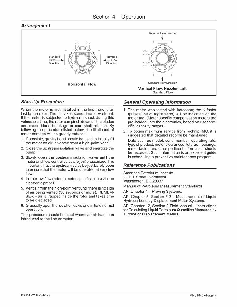
11. The meter can measure flow in either direction (forward and reverse).
For standard and reverse flow directions, see meter arrangements on page 5.

Page 4 • MN01046 Issue/Rev. 0.2 (4/17)
Section 3 – Electrical Installation
The HRE circuit board (Hall Rotary Encoder) utilizes the rotation of the magnetically coupled PD meter rotor and electronically senses the rotation to produce the Quadrature* output pulses. The encoder is completely isolated from the product and meter internals. Because the encoder and rotor rotation are magnetically coupled, no gear train or thrust bearing maintenance is needed.*Quadrature (Dual Output Signal) – Two discrete pulse channels are generated 90 electrical degrees out-of-phase with each other. By monitoring these signals with a pulse sequence comparator, (such as that found in the Smith Meter AccuLoad/microLoad series of equipment), the integrity of the pulse transmission system can be checked for pulse transmission errors (noise), mal-functioning transmitter, and faulty transmission cable. Additionally, reverse flow can be detected.
Terminal Connections: CN1
Terminal 1 + 10 - 30 VdcTerminal 2 "A" Signal (Leading)Terminal 3 "B" Signal (Lagging)Terminal 4 Logic Common (Ground)Terminal 5Terminal 6Terminal 7Terminal 8
No electrical connection on circuit board. These can be used for wiring connections or tie-ins (ex. RTD junction, etc.)
CautionWhen handling the HRE board, ensure that proper grounding and static buildup is not present in order to prevent damage to the board. Improper handling and static discharge will cause failure to the board.
Wire Connections
To ensure proper opera-tion and to avoid damage to the circuitry, check to make sure that all S1 dip switches are locked in the "OFF" position (closest to the terminal block).
Numbering and label for the connections can be located on the PCB and terminal block.
Note: the HRE is factory programmed specifically for the characteris-tics of the meter, and is marked with the serial number of the meter to ensure the link. Consult factory for proper replacement; do not install the HRE from one meter into another as improper measurement may occur. If the HRE circuit board is removed and replaced, be sure that all four screws that hold the HRE board are fully seated and the board is fixed flat and centered on the standoffs in the enclosure.

Issue/Rev. 0.2 (4/17) MN01046 • Page 5
Section 3 – Electrical Installation
Electrical Specifications
Electrical InputsDC Power Range:10 to 30 VdcInput Current:Quiescent Current (No Load): 20 mA @ 10 Vdc, 15 mA @ 24 Vdc, 15 mA @ 30 Vdc
Output Signal10 Vdc Input Power Supply:No Load: 9.7 ± 0.3 Vp-p square wave270 W Load: 7.6 ± 0.3 Vp-p square wave (minimum)24 Vdc Input Power Supply:No Load: 23.7 ± 0.3 Vp-p square wave270 W Load: 16 ± 0.3 Vp-p square wave (minimum)30 Vdc Input Power Supply:No Load: 29.7 ± 0.3 Vp-p square wave270 W Load: 21 ± 0.3 Vp-p square wave (minimum)
Output Source Current (A & B @ 270 Load):70 mA @ 10 Vdc, 130 mA @ 24 Vdc, 160 mA @ 30 Vdc
Output Current per Channel (A & B):Maximum Sink Current: 300 mA @ 30 VdcMaximum Source Current: 80 mA @ 30 Vdc
Electrical Installation
GeneralThe HRE circuit board is mounted in a Flame Proof (Explosion Proof) enclosure. The cable, conduit, and conduit fittings must meet installation requirements, such as hazardous area classifications, humidity, tem-perature, voltage, current, and others.
For ATEX and IEC InstallationsFor systems utilizing cable glands the cable entry must be in accordance to EN/IEC 60079-1 section 13. The gland and/or thread adapter must be Exd certified. The cable end must be securely installed and, depending on the cable type, be properly protected from mechanical damage. Wiring conductors and/or cable gland, if used, must have a temperature rating of at least 90°C.For systems utilizing rigid conduit, the conduit entry must be in accordance to EN/IEC 60079-1 sections 13, and Ex d certified stopping box (sealing device) must be used immediately at the entrance of the enclosure. (i.e.: within 50 mm). It is an end user requirement to ensure that any unused entries must be suitably blocked with an Ex d IIB IP65 certified plug for ATEX and IEC Ex applications.
For North American InstallationConduit connections must be in accordance to:USA – National Electric Code (NFPA 70) Canada – Canadian Electric Code (CSA C22.1)A listed seal off box must be used immediately at the entrance of the enclosure. (i.e.: within 3 inches) Any unused entry must be blocked with a metal listed plug.For North American zone applications, the plug must be listed metal close up type. A listed flexible conduit sec-tion meeting the requirements of the relevant standards for the area classification of at least 12" in length may be used to join the housing to the rigid conduit system. Additionally it is recommended that a listed conduit union be utilized for the connection to allow the removal of the housing for maintenance purposes.

Page 6 • MN01046 Issue/Rev. 0.2 (4/17)
Section 3 – Electrical Installation
All Installation NotesCaution: To prevent ignition of hazardous atmospheres, disconnect from supply circuit before opening. Keep tightly closed when circuits are in operation.Warning: Enclosure contains capacitors, to prevent ignition of hazardous atmospheres. Do not open unless area is known to be non-hazardous.Important: Cut unused shield back to the jacket insula-tion and tape. Terminate shield at receiving instrument only to prevent ground loops.Double check all field wire connections before applica-tion of power and operation. Incorrect wiring may dam-age or destroy circuitry.Do not short circuit or apply power to the pulse output terminals of the HRE or circuit damage could occur.Disconnect terminal plug from HRE before applying diagnostic signals to the cable if required for trouble-shooting purposes of the cabling.Warning: Make sure hazardous area is safe by follow-ing all locally prescribed safety precautions during the troubleshooting exercise.
Recommended Cable16-20 AWG stranded copper shielded cable, compatible with local requirements.Three-wire shielded for single-channel transmission and power.Four-wire shielded for dual-channel transmission and power.Four-wire shielded for temperature probe (if supplied), distances below do not apply, distance should be as short as possible and depends on installation conditions, long distance installations may require a user supplied four wire temperature transmitter.
Cable Size and Distances#20 AWG up to 2,000 ft. (610 m)#18 AWG up to 3,000 ft. (915 m)#16 AWG up to 5,000 ft. (1,525 m)
Note: Resistance between the ground terminal and the powersupply ground must not exceed 2 ohms.
Issue/Rev. 0.2 (4/17) MN01046 • Page 7
Section 4 – OperationArrangement
Start-Up ProcedureWhen the meter is first installed in the line there is air inside the rotor. The air takes some time to work out. If the meter is subjected to hydraulic shock during this vulnerable time, the rotor can pinch down on the blades and cause blade breakage or cam shaft rotation. By following the procedure listed below, the likelihood of meter damage will be greatly reduced.1. If possible, gravity head should be used to initially fill
the meter as air is vented from a high-point vent.2. Close the upstream isolation valve and energize the
pump.3. Slowly open the upstream isolation valve until the
meter and flow control valve are just pressurized. It is important that the upstream valve be just barely open to ensure that the meter will be operated at very low flow.
4. Initiate low flow (refer to meter specifications) via the electronic preset.
5. Vent air from the high-point vent until there is no sign of air being vented (30 seconds or more). REMEM-BER – air is trapped inside the rotor and takes time to be displaced.
6. Gradually open the isolation valve and initiate normal operation.
This procedure should be used whenever air has been introduced to the line or meter.
General Operating Information1. The meter was tested with kerosene; the K-factor
(pulses/unit of registration) will be indicated on the meter tag. (Meter specific compensation factors are pre-loaded into the electronics, based on user spe-cific viscosity ranges).
2. To obtain maximum service from TechnipFMC, it is suggested that detailed records be maintained.
Data such as model, serial number, operating rate, type of product, meter clearances, totalizer readings, meter factor, and other pertinent information should be recorded. Such information is an excellent guide in scheduling a preventive maintenance program.
Reference PublicationsAmerican Petroleum Institute2101 L Street, NorthwestWashington, DC 20037Manual of Petroleum Measurement Standards.API Chapter 4 – Proving Systems.API Chapter 5, Section 5.2 – Measurement of Liquid Hydrocarbons by Displacement Meter Systems.API Chapter 12, Section 2 Field Manual – Instructions for Calculating Liquid Petroleum Quantities Measured by Turbine or Displacement Meters.
Horizontal Flow
Standard Flow Direction
Reverse Flow
Direction
Vertical Flow, Nozzles Left Standard Flow
Reverse Flow Direction
Standard Flow Direction

TechnipFMC.com
FMCTechnologies.com/MeasurementSolutions
© TechnipFMC 2017 All rights reserved. MN01011 Issue/Rev. 1.0 (4/17)
TechnipFMCFMC Technologies Measurement Solutions, Inc.500 North Sam Houston Parkway West,Suite 100Houston, Texas 77067 USAP:+1 281.260.2190
USA Operation 1602 Wagner AvenueErie, Pennsylvania 16510 USAP:+1 814.898.5000
Germany Operation Smith Meter GmbHRegentstrasse 125474 Ellerbek, GermanyP:+49 4101 304.0
Revisions included in MN01046 Issue/Rev. 0.2 (4/17):Installation section split into separate mechanical and electrical installation. The electrical installation section information is a complete revision.The specifications contained herein are subject to change without notice and any user of said specifications should verify from the manufacturer that the specifications are currently in ef-fect. Otherwise, the manufacturer assumes no responsibility for the use of specifications which may have been changed and are no longer in effect.Contact information is subject to change. For the most current contact information, visit our website at TechnipFMC.com and click on the “Contact Us” link.
Contact Information: Field Service Response Center 24/7 Technical Support/Schedule a Technician: 1-844-798-3819 System Installation Supervision, Start-Up, Training, and Commissioning Services Available
Technical Support


![Untitled-4 [] · Standard lamineret (8 meter / *4 meter) Neon lamineret - 5 meter Mat lamineret - 8 meter / **5 meter) Metallic lamineret - 8 meter Ulamineret - 8 meter Fleksibel](https://img.dokumen.tips/doc/110x75/5f3a768af7b8e86a6437cff7/untitled-4-standard-lamineret-8-meter-4-meter-neon-lamineret-5-meter.jpg)