Embed Size (px)
Citation preview
www.zyxel.com
www.zyxel.com
MS-7206Modular Ethernet Switch System
Copyright © 2009 ZyXEL Communications Corporation
Firmware Version 3.85Edition 1, 10/2009
Default Login DetailsIP Address http://192.168.0.1
User Name admin
Password 1234

About This User's Guide
MS-7206 User’s Guide 3
About This User's Guide
Intended Audience
This manual is intended for people who want to configure the MM-7201. You should have at least a basic knowledge of TCP/IP and Ethernet networking concepts and topology.
Note: It is recommended you use the web configurator to configure the MM-7201.
Related Documentation• MS-7206 Hardware Installation Guide
Hardware guide for the MS-7206 system, including the MS-7206S, MI-7248, MI-7248PWR, MI-7248TF, MI-7526F, MF-7201, MP-7201, MPC-7202, MP-7202, and MP-7203.
• Command Line Interface (CLI) Reference Guide
Line commands offer an alternative to the web configurator and in some cases are necessary to configure advanced features.
• Web Configurator Online Help
Embedded web help for descriptions of individual screens and supplementary information.
• Supporting Disc
Refer to the included CD for support documents.
• ZyXEL Web Site
Please refer to www.zyxel.com for additional support documentation and product certifications.
Documentation Feedback
Send your comments, questions or suggestions to: [email protected]
Thank you!
The Technical Writing Team, ZyXEL Communications Corp.,6 Innovation Road II, Science-Based Industrial Park, Hsinchu, 30099, Taiwan.
About This User's Guide
MS-7206 User’s Guide4
Need More Help?
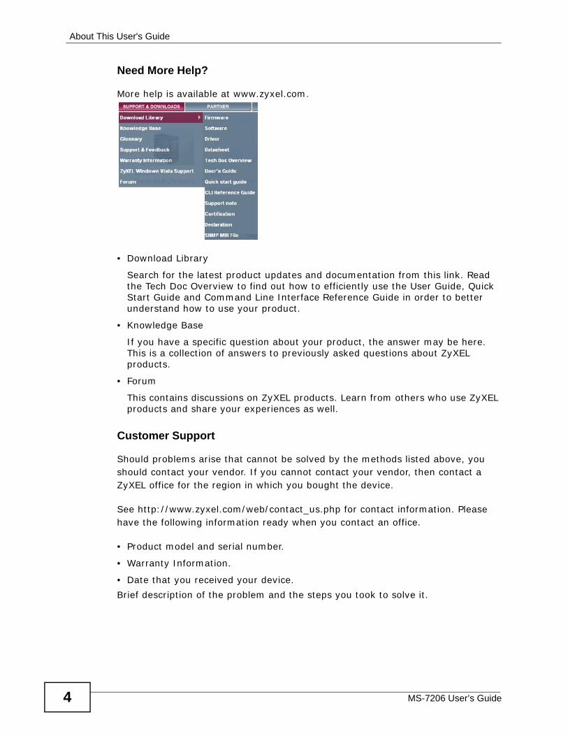
More help is available at www.zyxel.com.
• Download Library
Search for the latest product updates and documentation from this link. Read the Tech Doc Overview to find out how to efficiently use the User Guide, Quick Start Guide and Command Line Interface Reference Guide in order to better understand how to use your product.
• Knowledge Base
If you have a specific question about your product, the answer may be here. This is a collection of answers to previously asked questions about ZyXEL products.
• Forum
This contains discussions on ZyXEL products. Learn from others who use ZyXEL products and share your experiences as well.
Customer Support
Should problems arise that cannot be solved by the methods listed above, you should contact your vendor. If you cannot contact your vendor, then contact a ZyXEL office for the region in which you bought the device.
See http://www.zyxel.com/web/contact_us.php for contact information. Please have the following information ready when you contact an office.
• Product model and serial number.
• Warranty Information.
• Date that you received your device.
Brief description of the problem and the steps you took to solve it.
Document Conventions
MS-7206 User’s Guide 5
Document Conventions
Warnings and Notes
These are how warnings and notes are shown in this User’s Guide.
Warnings tell you about things that could harm you or your device.
Note: Notes tell you other important information (for example, other things you may need to configure or helpful tips) or recommendations.
Syntax Conventions• The MM-7201 may be referred to as the “MM-7201”, the “management card” or
the “product” in this User’s Guide.
• The “MS-7206 system” refers to the MS-7206 chassis and all the modules that are in the MS-7206 chassis. It is also referred to as the “system” or the “switch” in this User’s Guide.
• The “MS-7206 chassis” refers only to the main chassis of the MS-7206 system. It does not include any interface modules or management cards.
• Product labels, screen names, field labels and field choices are all in bold font.
• A key stroke is denoted by square brackets and uppercase text, for example, [ENTER] means the “enter” or “return” key on your keyboard.
• “Enter” means for you to type one or more characters and then press the [ENTER] key. “Select” or “choose” means for you to use one of the predefined choices.
• A right angle bracket ( > ) within a screen name denotes a mouse click. For example, Maintenance > Log > Log Setting means you first click Maintenance in the navigation panel, then the Log sub menu and finally the Log Setting tab to get to that screen.
• Units of measurement may denote the “metric” value or the “scientific” value. For example, “k” for kilo may denote “1000” or “1024”, “M” for mega may denote “1000000” or “1048576” and so on.
• “e.g.,” is a shorthand for “for instance”, and “i.e.,” means “that is” or “in other words”.
Document Conventions
MS-7206 User’s Guide6
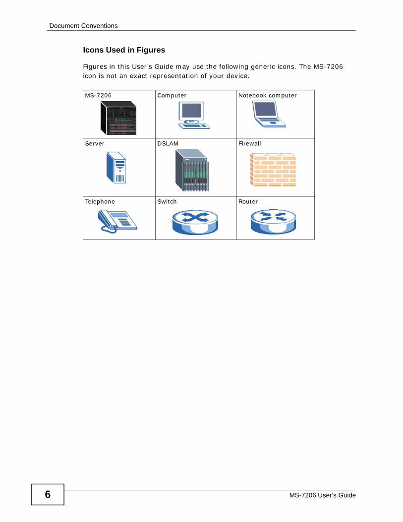
Icons Used in Figures
Figures in this User’s Guide may use the following generic icons. The MS-7206 icon is not an exact representation of your device.
MS-7206 Computer Notebook computer
Server DSLAM Firewall
Telephone Switch Router
Safety Warnings
MS-7206 User’s Guide 7
Safety Warnings
• Do NOT use this product near water, for example, in a wet basement or near a swimming pool.
• Do NOT expose your device to dampness, dust or corrosive liquids.• Do NOT store things on the device.• Do NOT install, use, or service this device during a thunderstorm. There is a remote risk
of electric shock from lightning.• Connect ONLY suitable accessories to the device.• ONLY qualified service personnel should service or disassemble this device.• Make sure to connect the cables to the correct ports.• Place connecting cables carefully so that no one will step on them or stumble over them.• Always disconnect all cables from this device before servicing or disassembling.• Do not use the device outside, and make sure all the connections are indoors. There is a
remote risk of electric shock from lightning.• CAUTION: RISK OF EXPLOSION IF BATTERY (on the motherboard) IS REPLACED BY AN
INCORRECT TYPE. DISPOSE OF USED BATTERIES ACCORDING TO THE INSTRUCTIONS. Dispose them at the applicable collection point for the recycling of electrical and electronic equipment. For detailed information about recycling of this product, please contact your local city office, your household waste disposal service or the store where you purchased the product.
• Do NOT obstruct the device ventilation slots, as insufficient airflow may harm your device.
• The PoE (Power over Ethernet) devices that supply or receive power and their connected Ethernet cables must all be completely indoors.
• Warning! To avoid risk of electric shock, remove only one card at a time and do not place fingers or objects inside the chassis. Cover empty slots with slot covers.
Your product is marked with this symbol, which is known as the WEEE mark.
WEEE stands for Waste Electronics and Electrical Equipment. It means that
used electrical and electronic products should not be mixed with general
waste. Used electrical and electronic equipment should be treated separately.

Safety Warnings
MS-7206 User’s Guide8
Contents Overview
MS-7206 User’s Guide 9
Contents Overview
Introduction ............................................................................................................................ 23
Introducing the MM-7201 ........................................................................................................... 25
Hardware ................................................................................................................................. 29
Front Panel ................................................................................................................................ 31Installing Cards .......................................................................................................................... 33
Basic ....................................................................................................................................... 37
The Web Configurator ............................................................................................................... 39Initial Setup Example ................................................................................................................. 49System Status and Port Statistics .............................................................................................. 55System Info ............................................................................................................................... 61General Setup ........................................................................................................................... 65Switch Setup .............................................................................................................................. 69IP Setup ..................................................................................................................................... 73Slot Setup .................................................................................................................................. 77Port Setup .................................................................................................................................. 79
Advanced ................................................................................................................................ 83
VLAN ......................................................................................................................................... 85Static MAC Forward Setup ...................................................................................................... 101Filtering .................................................................................................................................... 103Spanning Tree Protocol ........................................................................................................... 105Bandwidth Control ................................................................................................................... 127Broadcast Storm Control ......................................................................................................... 131Mirroring .................................................................................................................................. 133Link Aggregation ...................................................................................................................... 135Port Authentication .................................................................................................................. 143Port Security ............................................................................................................................ 149Classifier .................................................................................................................................. 155Policy Rule ............................................................................................................................... 161Queuing Method ...................................................................................................................... 169VLAN Stacking ......................................................................................................................... 173Multicast .................................................................................................................................. 179AAA ......................................................................................................................................... 195IP Source Guard ...................................................................................................................... 207Loop Guard .............................................................................................................................. 233
Contents Overview
MS-7206 User’s Guide10
IP ............................................................................................................................................ 239
Static Route ............................................................................................................................. 241RIP .......................................................................................................................................... 243OSPF ....................................................................................................................................... 245IGMP ....................................................................................................................................... 257DVMRP .................................................................................................................................... 259Differentiated Services ............................................................................................................. 263DHCP ...................................................................................................................................... 271VRRP ....................................................................................................................................... 281
Manage .................................................................................................................................. 291
Maintenance ............................................................................................................................ 293Access Control ........................................................................................................................ 301Diagnostic ................................................................................................................................ 321Syslog ...................................................................................................................................... 323Cluster Management ............................................................................................................... 327MAC Table ............................................................................................................................... 335IP Table .................................................................................................................................... 339ARP Table ................................................................................................................................ 343Routing Table ........................................................................................................................... 345Configure Clone ....................................................................................................................... 347
Troubleshooting and Product Specifications ................................................................... 351
Troubleshooting ....................................................................................................................... 353Product Specifications ............................................................................................................. 357
Appendices and Index ......................................................................................................... 367
Table of Contents
MS-7206 User’s Guide 11
Table of Contents
About This User's Guide ..........................................................................................................3
Document Conventions............................................................................................................5
Safety Warnings........................................................................................................................7
Contents Overview ...................................................................................................................9
Table of Contents.................................................................................................................... 11
Part I: Introduction................................................................................. 23
Chapter 1Introducing the MM-7201........................................................................................................25
1.1 Overview .............................................................................................................................. 251.2 Ways to Manage the MM-7201 ............................................................................................ 261.3 Good Habits for Managing the MM-7201 ............................................................................. 261.4 LEDs .................................................................................................................................... 27
Part II: Hardware .................................................................................... 29
Chapter 2Front Panel .............................................................................................................................. 31
2.1 Front Panel .......................................................................................................................... 312.2 Connections ......................................................................................................................... 31
2.2.1 MGMT Port ................................................................................................................. 312.2.2 CONSOLE Port .......................................................................................................... 322.2.3 ALARM Port ............................................................................................................... 32
Chapter 3Installing Cards ....................................................................................................................... 33
3.1 Management Cards ............................................................................................................. 333.1.1 Add a Management Card (System Is Off) .................................................................. 333.1.2 Add a Management Card (System Is On) .................................................................. 343.1.3 Remove a Management Card .................................................................................... 34
3.2 Interface Modules ................................................................................................................ 343.2.1 Add an Interface Module (System Is Off) ................................................................... 34
Table of Contents
MS-7206 User’s Guide12
3.2.2 Add an Interface Module (System Is On) ................................................................... 343.2.3 Remove an Interface Module ..................................................................................... 36
Part III: Basic .......................................................................................... 37
Chapter 4The Web Configurator ............................................................................................................ 39
4.1 Introduction .......................................................................................................................... 394.2 System Login .................................................................................................................... 394.3 The Status Screen .......................................................................................................... 40
4.3.1 Change Your Password .......................................................................................... 444.4 Saving Your Configuration ................................................................................................... 444.5 Switch Lockout .................................................................................................................... 454.6 Resetting the Switch ......................................................................................................... 454.7 Logging Out of the Web Configurator .................................................................................. 464.8 Help .................................................................................................................................... 47
Chapter 5Initial Setup Example.............................................................................................................. 49
5.1 Configuring an IP Interface .................................................................................................. 495.2 Configuring DHCP Server Settings ..................................................................................... 505.3 Creating a VLAN .................................................................................................................. 515.4 Setting Port VID ................................................................................................................... 525.5 Enabling RIP ........................................................................................................................ 53
Chapter 6System Status and Port Statistics......................................................................................... 55
6.1 Status ................................................................................................................................... 556.1.1 Port Status .................................................................................................................. 566.1.2 Port Details ................................................................................................................. 57
Chapter 7System Info .............................................................................................................................61
7.1 System Info .......................................................................................................................... 617.1.1 Hardware Monitor ....................................................................................................... 63
Chapter 8General Setup.......................................................................................................................... 65
8.1 General Setup .................................................................................................................... 65
Chapter 9Switch Setup ........................................................................................................................... 69
Table of Contents
MS-7206 User’s Guide 13
9.1 Switch Setup ........................................................................................................................ 69
Chapter 10IP Setup.................................................................................................................................... 73
10.1 IP Interfaces ...................................................................................................................... 7310.2 IP Setup ............................................................................................................................. 74
Chapter 11Slot Setup ................................................................................................................................ 77
11.1 Slot Setup .......................................................................................................................... 77
Chapter 12Port Setup................................................................................................................................ 79
12.1 Port Setup .......................................................................................................................... 79
Part IV: Advanced .................................................................................. 83
Chapter 13VLAN ........................................................................................................................................ 85
13.1 Introduction to VLANs ........................................................................................................ 8513.2 Introduction to IEEE 802.1Q Tagged VLANs ................................................................ 85
13.2.1 Forwarding Tagged and Untagged Frames .............................................................. 8613.3 Automatic VLAN Registration ............................................................................................ 86
13.3.1 GARP ....................................................................................................................... 8613.3.2 GVRP ....................................................................................................................... 87
13.4 Port VLAN Trunking ........................................................................................................... 8713.5 Static VLAN ....................................................................................................................... 8813.6 VLAN Status ..................................................................................................................... 89
13.6.1 VLAN Detail .............................................................................................................. 8913.6.2 Static VLAN .......................................................................................................... 9113.6.3 VLAN Port Setting ................................................................................................ 93
13.7 Subnet Based VLANs ....................................................................................................... 9413.8 Configuring Subnet Based VLAN .................................................................................... 9513.9 Protocol Based VLANs ..................................................................................................... 9713.10 Configuring Protocol Based VLAN ................................................................................ 9813.11 Create an IP-based VLAN Example .............................................................................. 100
Chapter 14Static MAC Forward Setup................................................................................................... 101
14.1 Static MAC Forwarding ............................................................................................... 101
Table of Contents
MS-7206 User’s Guide14
Chapter 15Filtering.................................................................................................................................. 103
15.1 Filtering ........................................................................................................................... 103
Chapter 16Spanning Tree Protocol........................................................................................................ 105
16.1 STP/RSTP Overview ...................................................................................................... 10516.1.1 STP Terminology ................................................................................................... 10516.1.2 How STP Works .................................................................................................... 10616.1.3 STP Port States ..................................................................................................... 10716.1.4 Multiple RSTP ....................................................................................................... 10716.1.5 Multiple STP ........................................................................................................... 108
16.2 Spanning Tree Protocol Status Screen .............................................................................11116.3 Spanning Tree Configuration ...........................................................................................11116.4 Rapid Spanning Tree Protocol .......................................................................................11216.5 Rapid Spanning Tree Protocol Status .........................................................................11416.6 Multiple Rapid Spanning Tree Protocol .........................................................................11616.7 Multiple Rapid Spanning Tree Protocol Status ...........................................................11816.8 Configure Multiple Spanning Tree Protocol .................................................................. 12016.9 Multiple Spanning Tree Protocol Status ...................................................................... 123
Chapter 17Bandwidth Control................................................................................................................ 127
17.1 CIR and PIR .................................................................................................................... 12717.2 Bandwidth Control ........................................................................................................... 127
Chapter 18Broadcast Storm Control ..................................................................................................... 131
18.1 Broadcast Storm Control ................................................................................................. 131
Chapter 19Mirroring ................................................................................................................................ 133
19.1 Mirroring .......................................................................................................................... 133
Chapter 20Link Aggregation .................................................................................................................. 135
20.1 Link Aggregation Overview ............................................................................................. 13520.2 Dynamic Link Aggregation .............................................................................................. 135
20.2.1 Link Aggregation ID ............................................................................................... 13620.3 Link Aggregation Status .................................................................................................. 13720.4 Link Aggregation Setting ................................................................................................ 13820.5 Link Aggregation Control Protocol ................................................................................. 140
Table of Contents
MS-7206 User’s Guide 15
Chapter 21Port Authentication............................................................................................................... 143
21.1 Port Authentication Overview ......................................................................................... 14321.1.1 IEEE 802.1x Authentication ................................................................................... 14321.1.2 MAC Authentication ............................................................................................... 144
21.2 Port Authentication .......................................................................................................... 14521.2.1 802.1x ................................................................................................................. 14621.2.2 MAC Authentication .............................................................................................. 147
Chapter 22Port Security.......................................................................................................................... 149
22.1 Port Security ................................................................................................................... 14922.2 VLAN MAC Address Limit .............................................................................................. 152
Chapter 23Classifier................................................................................................................................ 155
23.1 Packet Classifier and QoS ............................................................................................... 15523.2 Classifier ......................................................................................................................... 15523.3 Classifier Example ........................................................................................................... 159
Chapter 24Policy Rule............................................................................................................................. 161
24.1 Policy Rules Overview .................................................................................................... 16124.1.1 DiffServ .................................................................................................................. 16124.1.2 DSCP and Per-Hop Behavior ................................................................................. 161
24.2 Configuring Policy Rules ................................................................................................. 16224.3 Policy Example ................................................................................................................ 166
Chapter 25Queuing Method.................................................................................................................... 169
25.1 Queuing Method Overview ............................................................................................. 16925.1.1 Strictly Priority Queuing .......................................................................................... 16925.1.2 Weighted Round Robin Scheduling (WRR) ........................................................... 16925.1.3 Weighted Fair Queuing .......................................................................................... 170
25.2 Queuing Method .............................................................................................................. 171
Chapter 26VLAN Stacking ...................................................................................................................... 173
26.1 VLAN Stacking Overview ................................................................................................. 17326.1.1 VLAN Stacking Example ........................................................................................ 173
26.2 VLAN Stacking Port Roles ............................................................................................... 17426.3 VLAN Tag Format ............................................................................................................ 175
26.3.1 Frame Format ........................................................................................................ 175
Table of Contents
MS-7206 User’s Guide16
26.4 VLAN Stacking ................................................................................................................. 176
Chapter 27Multicast ................................................................................................................................ 179
27.1 Multicast Overview ......................................................................................................... 17927.1.1 IP Multicast Addresses ........................................................................................... 17927.1.2 IGMP Filtering ........................................................................................................ 17927.1.3 IGMP Snooping ..................................................................................................... 18027.1.4 IGMP Snooping and VLANs ................................................................................... 180
27.2 Multicast Status .............................................................................................................. 18027.3 Multicast Setting ............................................................................................................. 18127.4 IGMP Snooping VLAN .................................................................................................... 18327.5 IGMP Filtering Profile ..................................................................................................... 18527.6 MVR Overview ................................................................................................................. 186
27.6.1 Types of MVR Ports ............................................................................................... 18727.6.2 MVR Modes ........................................................................................................... 18727.6.3 How MVR Works .................................................................................................... 187
27.7 MVR ................................................................................................................................. 18827.8 Group Configuration ....................................................................................................... 190
27.8.1 MVR Configuration Example .................................................................................. 192
Chapter 28AAA ........................................................................................................................................ 195
28.1 Authentication, Authorization and Accounting (AAA) ..................................................... 19528.1.1 Local User Accounts .............................................................................................. 19628.1.2 RADIUS and TACACS+ ........................................................................................ 196
28.2 AAA Screens ................................................................................................................... 19628.2.1 RADIUS Server Setup ........................................................................................ 19728.2.2 TACACS+ Server Setup ..................................................................................... 19928.2.3 AAA Setup ............................................................................................................. 20128.2.4 Vendor Specific Attribute ........................................................................................ 20428.2.5 Tunnel Protocol Attribute ........................................................................................ 205
Chapter 29IP Source Guard.................................................................................................................... 207
29.1 IP Source Guard Overview .............................................................................................. 20729.1.1 DHCP Snooping Overview ..................................................................................... 20829.1.2 ARP Inspection Overview ...................................................................................... 210
29.2 IP Source Guard ...............................................................................................................21129.3 IP Source Guard Static Binding ....................................................................................... 21229.4 DHCP Snooping .............................................................................................................. 21529.5 DHCP Snooping Configure .............................................................................................. 218
29.5.1 DHCP Snooping Port Configure ............................................................................. 220
Table of Contents
MS-7206 User’s Guide 17
29.5.2 DHCP Snooping VLAN Configure .......................................................................... 22129.6 ARP Inspection Status ..................................................................................................... 223
29.6.1 ARP Inspection VLAN Status ................................................................................. 22429.6.2 ARP Inspection Log Status .................................................................................... 225
29.7 ARP Inspection Configure ............................................................................................... 22629.7.1 ARP Inspection Port Configure .............................................................................. 22829.7.2 ARP Inspection VLAN Configure ........................................................................... 230
Chapter 30Loop Guard............................................................................................................................ 233
30.1 Loop Guard Overview ..................................................................................................... 23330.2 Loop Guard Setup ........................................................................................................... 235
Part V: IP ............................................................................................... 239
Chapter 31Static Route ...........................................................................................................................241
31.1 Static Routing ................................................................................................................. 241
Chapter 32RIP ......................................................................................................................................... 243
32.1 RIP ................................................................................................................................... 243
Chapter 33OSPF ...................................................................................................................................... 245
33.1 OSPF Overview .............................................................................................................. 24533.1.1 OSPF Autonomous Systems and Areas ................................................................ 24533.1.2 How OSPF Works .................................................................................................. 24633.1.3 Interfaces and Virtual Links .................................................................................... 24633.1.4 OSPF and Router Elections ................................................................................... 24733.1.5 Configuring OSPF ................................................................................................. 247
33.2 OSPF Status ................................................................................................................. 24833.3 OSPF Configuration ....................................................................................................... 25033.4 OSPF Interface ............................................................................................................... 25233.5 OSPF Virtual-Link ........................................................................................................... 255
Chapter 34IGMP....................................................................................................................................... 257
34.1 IGMP ............................................................................................................................... 257
Chapter 35DVMRP................................................................................................................................... 259
Table of Contents
MS-7206 User’s Guide18
35.1 DVMRP Overview ............................................................................................................ 25935.2 How DVMRP Works ........................................................................................................ 259
35.2.1 DVMRP Terminology ............................................................................................. 26035.3 DVMRP ............................................................................................................................ 260
35.3.1 DVMRP Configuration Error Messages ................................................................ 26135.4 Default DVMRP Timer Values ........................................................................................ 262
Chapter 36Differentiated Services ......................................................................................................... 263
36.1 DiffServ Overview ........................................................................................................... 26336.1.1 DSCP and Per-Hop Behavior ................................................................................ 26336.1.2 DiffServ Network Example .................................................................................... 264
36.2 Two Rate Three Color Marker Traffic Policing ................................................................. 26436.2.1 TRTCM-Color-blind Mode ...................................................................................... 26536.2.2 TRTCM-Color-aware Mode .................................................................................... 265
36.3 DiffServ ............................................................................................................................ 26636.4 2-Rate 3 Color Marker .................................................................................................... 26736.5 DSCP Setting ................................................................................................................. 269
Chapter 37DHCP...................................................................................................................................... 271
37.1 DHCP Overview ............................................................................................................. 27137.1.1 DHCP modes ........................................................................................................ 27137.1.2 DHCP Configuration Options ................................................................................. 271
37.2 DHCP Status ................................................................................................................... 27237.3 DHCP Relay .................................................................................................................... 272
37.3.1 DHCP Relay Agent Information ............................................................................. 27337.3.2 Configuring DHCP Global Relay ............................................................................ 27437.3.3 Global DHCP Relay Configuration Example .......................................................... 275
37.4 Configuring DHCP VLAN Settings ................................................................................ 27637.4.1 DHCP VLAN Setting Example ............................................................................... 278
Chapter 38VRRP...................................................................................................................................... 281
38.1 VRRP Overview .............................................................................................................. 28138.1.1 VRRP Parameters ................................................................................................. 282
38.2 VRRP Status ................................................................................................................... 28338.2.1 VRRP Configuration ............................................................................................... 284
38.3 VRRP Configuration Examples ...................................................................................... 28638.3.1 One Subnet Network Example .............................................................................. 28638.3.2 Two Subnets Example ........................................................................................... 288
Table of Contents
MS-7206 User’s Guide 19
Part VI: Manage .................................................................................... 291
Chapter 39Maintenance .......................................................................................................................... 293
39.1 Maintenance .................................................................................................................... 29339.1.1 Firmware Upgrade ................................................................................................. 29439.1.2 Restore Configuration ............................................................................................ 29639.1.3 Backup Configuration ............................................................................................. 296
39.2 FTP Command Line ........................................................................................................ 29739.2.1 Filename Conventions .......................................................................................... 29739.2.2 FTP Command Line Procedure ............................................................................. 29939.2.3 GUI-based FTP Clients .......................................................................................... 30039.2.4 FTP Restrictions .................................................................................................... 300
Chapter 40Access Control...................................................................................................................... 301
40.1 Access Control ................................................................................................................ 30140.2 SNMP Overview .............................................................................................................. 301
40.2.1 SNMP v3 and Security ........................................................................................... 30340.2.2 Supported MIBs ..................................................................................................... 30340.2.3 SNMP Traps .......................................................................................................... 30340.2.4 SNMP ..................................................................................................................... 30840.2.5 Configuring SNMP Trap Group ........................................................................... 310
40.3 Logins ...............................................................................................................................31140.4 SSH Overview ................................................................................................................. 313
40.4.1 How SSH works ..................................................................................................... 31340.4.2 SSH Implementation on the Switch ........................................................................ 314
40.5 Introduction to HTTPS ..................................................................................................... 31440.5.1 HTTPS Example .................................................................................................... 315
40.6 Service Access Control ................................................................................................... 31940.7 Remote Management ................................................................................................... 320
Chapter 41Diagnostic.............................................................................................................................. 321
41.1 Diagnostic ....................................................................................................................... 321
Chapter 42Syslog .................................................................................................................................... 323
42.1 Syslog Overview .............................................................................................................. 32342.2 Syslog Setup ................................................................................................................... 324
42.2.1 Syslog Server Setup ............................................................................................. 325
Table of Contents
MS-7206 User’s Guide20
Chapter 43Cluster Management.............................................................................................................327
43.1 Cluster Management Status Overview ............................................................................ 32743.2 Clustering Management Status ....................................................................................... 328
43.2.1 Cluster Member Switch Management ................................................................... 32943.2.2 Uploading Firmware to a Cluster Member Switch ................................................ 330
43.3 Clustering Management Configuration ............................................................................ 332
Chapter 44MAC Table.............................................................................................................................. 335
44.1 MAC Table Overview ....................................................................................................... 33544.2 MAC Table ....................................................................................................................... 336
Chapter 45IP Table .................................................................................................................................. 339
45.1 IP Table Overview ............................................................................................................ 33945.2 IP Table ............................................................................................................................ 340
Chapter 46ARP Table .............................................................................................................................. 343
46.1 ARP Table Overview ....................................................................................................... 34346.1.1 How ARP Works .................................................................................................... 343
46.2 ARP Table ........................................................................................................................ 344
Chapter 47Routing Table ........................................................................................................................ 345
47.1 Routing Table Status ........................................................................................................ 345
Chapter 48Configure Clone .................................................................................................................... 347
48.1 Configure Clone ............................................................................................................... 347
Part VII: Troubleshooting and Product Specifications..................... 351
Chapter 49Troubleshooting.................................................................................................................... 353
49.1 Power, Hardware Connections, and LEDs ...................................................................... 35349.2 MM-7201 Access and Login ............................................................................................ 354
Chapter 50Product Specifications .........................................................................................................357
Table of Contents
MS-7206 User’s Guide 21
Part VIII: Appendices and Index ......................................................... 367
Appendix A IP Addresses and Subnetting ........................................................................... 369
Appendix B Legal Information .............................................................................................. 381
Index....................................................................................................................................... 385

Table of Contents
MS-7206 User’s Guide22

23
PART IIntroduction
Introducing the MM-7201 (25)

24
MS-7206 User’s Guide 25
CHAPTER 1 Introducing the MM-7201
This chapter introduces the main applications and features of the MM-7201. It also introduces the ways you can manage the MM-7201.
1.1 OverviewThe MM-7201 is the management card for the MS-7206 Ethernet chassis system. The MM-7201 contains the configuration of the MS-7206 system and makes the interface modules work together as one switch.
Install one or two MM-7201 in each MS-7206 chassis.
• If you install one MM-7201, the MS-7206 system has a switching capability of 96 Gbps full duplex, the equivalent of two MI-7248 interface modules.
• If you install two MM-7201s, the MS-7206 system has a switching capability of 192 Gbps full duplex, the equivalent of four MI-7248 interface modules. In addition, the two MM-7201s provide switching and management redundancy. If one MM-7201 becomes unavailable, the other one takes over.
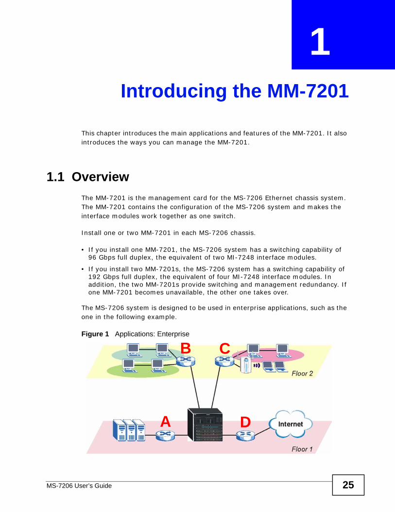
The MS-7206 system is designed to be used in enterprise applications, such as the one in the following example.
Figure 1 Applications: Enterprise
A
B C
D
Chapter 1 Introducing the MM-7201
MS-7206 User’s Guide26
In this example, the MS-7206 system is connected to three Gigabit Ethernet switches A, B, and C and one router D.
• Switch A provides access to the servers in the data center. The MS-7206 system uses link aggregation (trunking) to create a high-speed connection with switch A.
• Switches B and C are connected to users in different departments via wired or wireless networks. The MS-7206 system is connected to these switches using fiber.
• Router D provides secure Internet access for the whole company. The MS-7206 system is connected to router D by a 10/100 Mbps copper connection.
In this configuration, the MS-7206 system provides high switching capacity, high port density, and centralized management for the enterprise network.
1.2 Ways to Manage the MM-7201Use any of the following methods to manage the MM-7201.
• Web Configurator. This is recommended for everyday management of the MM-7201 using a (supported) web browser.
• Command Line Interface. Line commands are mostly used for troubleshooting by service engineers. See the CLI Reference Guide.
• FTP. FTP is used for firmware upgrades and configuration backup/restore. See Chapter 39 on page 293.
• SNMP. The device can be monitored by an SNMP manager. See Chapter 40 on page 301.
1.3 Good Habits for Managing the MM-7201Do the following things regularly to make the MM-7201 more secure and to manage the MM-7201 more effectively.
• Change the password. Use a password that’s not easy to guess and that consists of different types of characters, such as numbers and letters.
• Write down the password and put it in a safe place.
• Back up the configuration (and make sure you know how to restore it). Restoring an earlier working configuration may be useful if the device becomes unstable or even crashes. If you forget your password, you will have to reset the MM-7201 to its factory default settings. If you backed up an earlier configuration file, you would not have to totally re-configure the MM-7201. You could simply restore your last configuration.
Chapter 1 Introducing the MM-7201
MS-7206 User’s Guide 27
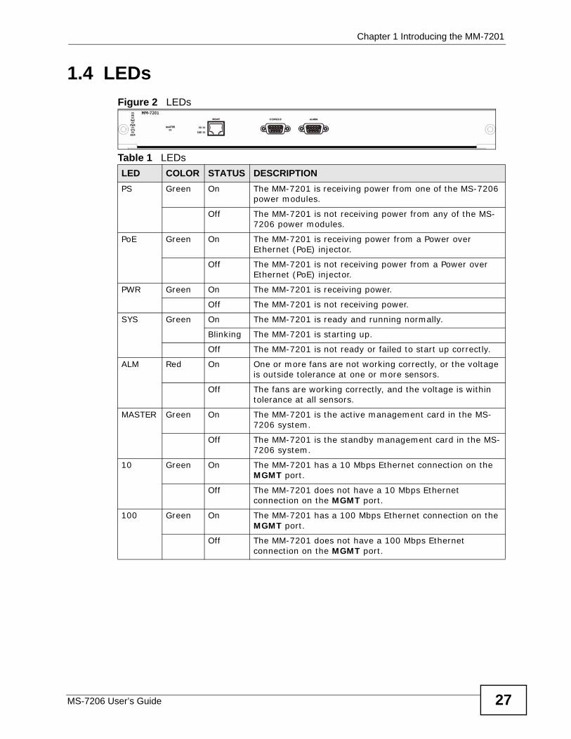
1.4 LEDsFigure 2 LEDs
Table 1 LEDsLED COLOR STATUS DESCRIPTIONPS Green On The MM-7201 is receiving power from one of the MS-7206
power modules.
Off The MM-7201 is not receiving power from any of the MS-7206 power modules.
PoE Green On The MM-7201 is receiving power from a Power over Ethernet (PoE) injector.
Off The MM-7201 is not receiving power from a Power over Ethernet (PoE) injector.
PWR Green On The MM-7201 is receiving power.
Off The MM-7201 is not receiving power.
SYS Green On The MM-7201 is ready and running normally.
Blinking The MM-7201 is starting up.
Off The MM-7201 is not ready or failed to start up correctly.
ALM Red On One or more fans are not working correctly, or the voltage is outside tolerance at one or more sensors.
Off The fans are working correctly, and the voltage is within tolerance at all sensors.
MASTER Green On The MM-7201 is the active management card in the MS-7206 system.
Off The MM-7201 is the standby management card in the MS-7206 system.
10 Green On The MM-7201 has a 10 Mbps Ethernet connection on the MGMT port.
Off The MM-7201 does not have a 10 Mbps Ethernet connection on the MGMT port.
100 Green On The MM-7201 has a 100 Mbps Ethernet connection on the MGMT port.
Off The MM-7201 does not have a 100 Mbps Ethernet connection on the MGMT port.

Chapter 1 Introducing the MM-7201
MS-7206 User’s Guide28

29
PART IIHardware
Front Panel (31)
Installing Cards (33)

30
MS-7206 User’s Guide 31
CHAPTER 2 Front Panel
This chapter describes the front panel of and connections to the MM-7201.
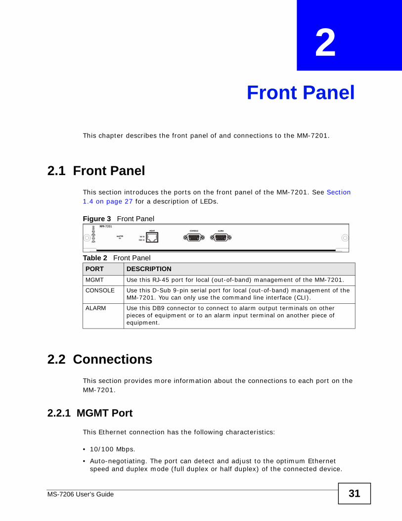
2.1 Front PanelThis section introduces the ports on the front panel of the MM-7201. See Section 1.4 on page 27 for a description of LEDs.
Figure 3 Front Panel
2.2 ConnectionsThis section provides more information about the connections to each port on the MM-7201.
2.2.1 MGMT PortThis Ethernet connection has the following characteristics:
• 10/100 Mbps.
• Auto-negotiating. The port can detect and adjust to the optimum Ethernet speed and duplex mode (full duplex or half duplex) of the connected device.
Table 2 Front PanelPORT DESCRIPTIONMGMT Use this RJ-45 port for local (out-of-band) management of the MM-7201.
CONSOLE Use this D-Sub 9-pin serial port for local (out-of-band) management of the MM-7201. You can only use the command line interface (CLI).
ALARM Use this DB9 connector to connect to alarm output terminals on other pieces of equipment or to an alarm input terminal on another piece of equipment.
Chapter 2 Front Panel
MS-7206 User’s Guide32
• Auto-crossover or auto-MDI/MDI-X. The port automatically works with a straight-through or crossover Ethernet cable.
2.2.2 CONSOLE PortFor local management through the command line interface (CLI), use a computer with terminal emulation software configured to the following parameters:
• VT100 terminal emulation
• 9600 bps
• No parity, 8 data bits, 1 stop bit
• No flow control
Connect the male 9-pin end of the console cable to the CONSOLE port of the MM-7201. Connect the female end to a serial port (COM1, COM2 or other COM port) of your computer.
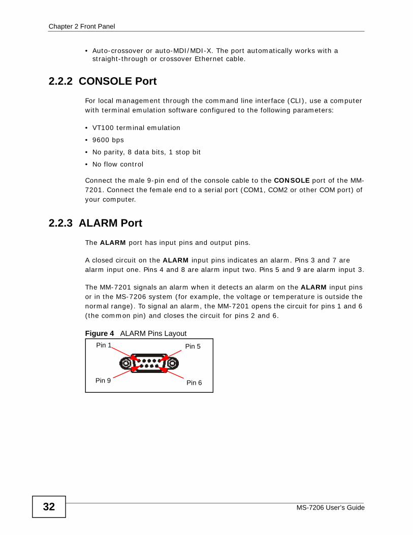
2.2.3 ALARM PortThe ALARM port has input pins and output pins.
A closed circuit on the ALARM input pins indicates an alarm. Pins 3 and 7 are alarm input one. Pins 4 and 8 are alarm input two. Pins 5 and 9 are alarm input 3.
The MM-7201 signals an alarm when it detects an alarm on the ALARM input pins or in the MS-7206 system (for example, the voltage or temperature is outside the normal range). To signal an alarm, the MM-7201 opens the circuit for pins 1 and 6 (the common pin) and closes the circuit for pins 2 and 6.
Figure 4 ALARM Pins Layout
Pin 5
Pin 6
Pin 1
Pin 9
MS-7206 User’s Guide 33
CHAPTER 3 Installing Cards
This chapter describes how to add, remove, and hot-swap management cards and interface modules in the system.
3.1 Management CardsThis section describes the steps required to add and remove management cards. If you want to hot-swap management cards, follow the steps below to remove the existing management card and add the new management card.
Note: Be careful when you remove a management card from one MS-7206 system and install it in a different MS-7206 system because it is possible that the two MS-7206 systems will have the same MAC address.
In the MS-7206 system, the MAC address comes from the management card, not the MS-7206 chassis. Each management card has a different MAC address. The MS-7206 system copies the MAC address from the active management card when the MS-7206 system starts up. The MS-7206 system keeps using this MAC address, even if the standby management card takes over, until the system starts up again. As a result, it is possible for two or more MS-7206 systems to have the same MAC address at the same time if the same management card was active when each of them last started up.
You can install management cards in slot 1 or slot 2.
3.1.1 Add a Management Card (System Is Off)
1 Insert the card in the MS-7206 chassis.
2 Turn on the system.
If you insert the management card in slot 1, it automatically becomes the active management card. If you insert the management card in slot 2, it becomes the standby management card if there is another management card in slot 1.
Chapter 3 Installing Cards
MS-7206 User’s Guide34
3.1.2 Add a Management Card (System Is On)Insert the card in the MS-7206 chassis.
If there is another management card in the system, the new management card automatically becomes the standby management card. If the firmware version of the new management card is different than the firmware version of the existing management card, the new management card does not function in the system.
3.1.3 Remove a Management CardRemove the card from the MS-7206 chassis. If you remove the active management card, the standby management card takes over.
3.2 Interface ModulesThis section describes the steps required to add and remove interface modules. If you want to hot-swap interface modules, follow the steps below to remove the existing interface module and add the new interface module.
You can install interface modules in slot 3, slot 4, slot 5, or slot 6.
3.2.1 Add an Interface Module (System Is Off)
1 Insert the card in the MS-7206 chassis.
2 Turn on the system.
The system automatically detects what type of interface module is installed. You do not have to configure the Slot Setup screen.
3.2.2 Add an Interface Module (System Is On)If the same type of interface module was previously installed in the slot, insert the card in the MS-7206 chassis.
If a different type of interface module was previously installed in the slot or if no interface module was previously installed in the slot, follow these steps.
Chapter 3 Installing Cards
MS-7206 User’s Guide 35
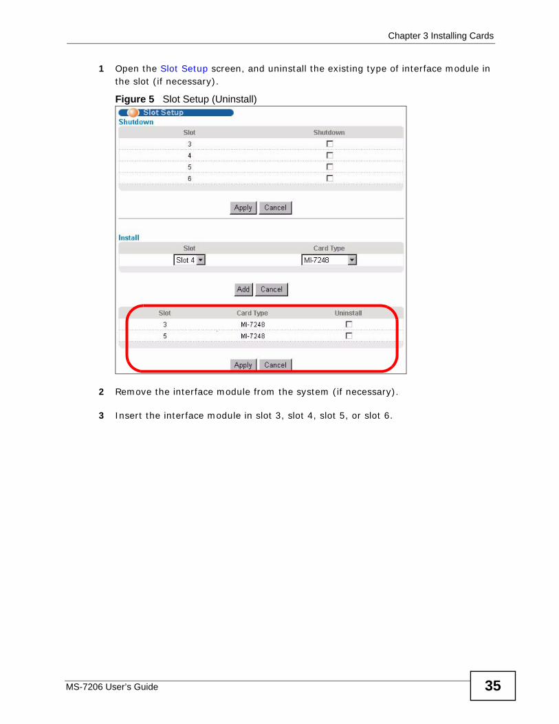
1 Open the Slot Setup screen, and uninstall the existing type of interface module in the slot (if necessary).
Figure 5 Slot Setup (Uninstall)
2 Remove the interface module from the system (if necessary).
3 Insert the interface module in slot 3, slot 4, slot 5, or slot 6.
Chapter 3 Installing Cards
MS-7206 User’s Guide36
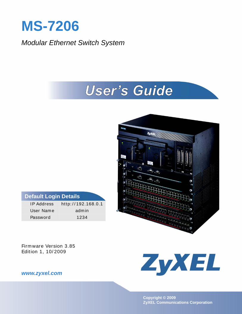
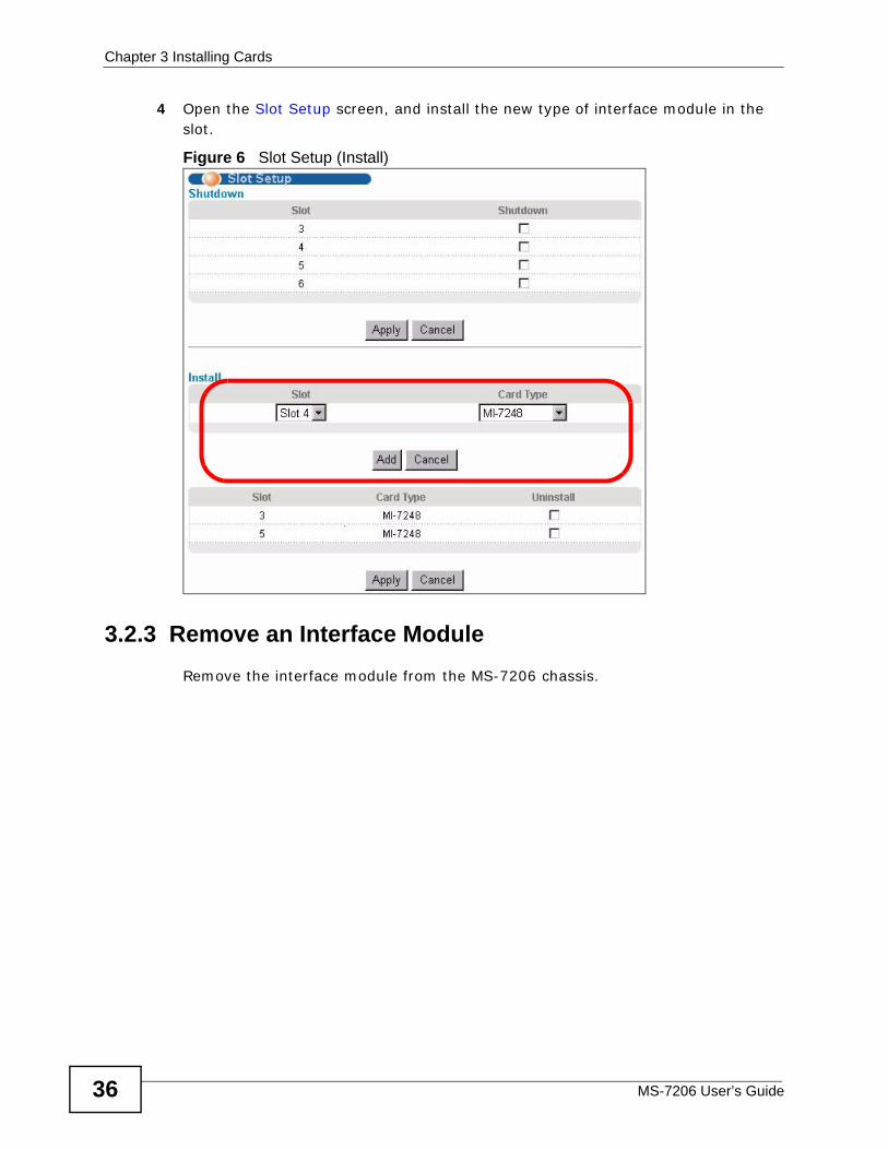
4 Open the Slot Setup screen, and install the new type of interface module in the slot.
Figure 6 Slot Setup (Install)
3.2.3 Remove an Interface ModuleRemove the interface module from the MS-7206 chassis.
37
PART IIIBasic
The Web Configurator (39)
Initial Setup Example (49)
System Status and Port Statistics (55)
System Info (61)
General Setup (65)
Switch Setup (69)
IP Setup (73)
Slot Setup (77)
Port Setup (79)

38
MS-7206 User’s Guide 39
CHAPTER 4 The Web Configurator
This section introduces the configuration and functions of the web configurator.
4.1 IntroductionThe web configurator is an HTML-based management interface that allows easy setup and management via Internet browser. Use Internet Explorer 6.0 and later or Netscape Navigator 7.0 and later versions. The recommended screen resolution is 1024 by 768 pixels.
In order to use the web configurator you need to allow:
• Web browser pop-up windows from the system. Web pop-up blocking is enabled by default in Windows XP SP (Service Pack) 2.
• JavaScript (enabled by default).
• Java permissions (enabled by default).
4.2 System Login
1 Start your web browser.
2 Type “http://” and the IP address of the system (the default management IP address is 192.168.0.1 through the MGMT port) in the Location or Address field. Press [ENTER].
Chapter 4 The Web Configurator
MS-7206 User’s Guide40
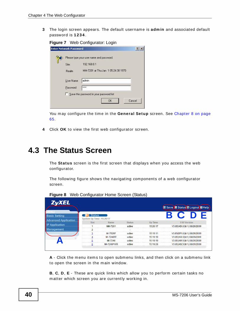
3 The login screen appears. The default username is admin and associated default password is 1234.
Figure 7 Web Configurator: Login
You may configure the time in the General Setup screen. See Chapter 8 on page 65.
4 Click OK to view the first web configurator screen.
4.3 The Status Screen The Status screen is the first screen that displays when you access the web configurator.
The following figure shows the navigating components of a web configurator screen.
Figure 8 Web Configurator Home Screen (Status)
A - Click the menu items to open submenu links, and then click on a submenu link to open the screen in the main window.
B, C, D, E - These are quick links which allow you to perform certain tasks no matter which screen you are currently working in.
A
B C D E
Chapter 4 The Web Configurator
MS-7206 User’s Guide 41
B - Click this link to save your configuration into the MM-7201’s nonvolatile memory. Nonvolatile memory is the configuration of your MM-7201 that stays the same even if the MM-7201’s power is turned off.
C - Click this link to go to the status page of the system.
D - Click this link to log out of the web configurator.
E - Click this link to display web help pages. The help pages provide descriptions for all of the configuration screens.
In the navigation panel, click a main link to reveal a list of submenu links.
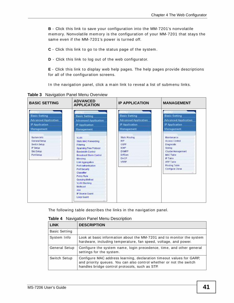
The following table describes the links in the navigation panel.
Table 3 Navigation Panel Menu Overview
BASIC SETTING ADVANCED APPLICATION IP APPLICATION MANAGEMENT
Table 4 Navigation Panel Menu DescriptionLINK DESCRIPTION Basic Setting
System Info Look at basic information about the MM-7201 and to monitor the system hardware, including temperature, fan speed, voltage, and power.
General Setup Configure the system name, login precedence, time, and other general settings for the system.
Switch Setup Configure MAC address learning, declaration timeout values for GARP, and priority queues. You can also control whether or not the switch handles bridge control protocols, such as STP.
Chapter 4 The Web Configurator
MS-7206 User’s Guide42
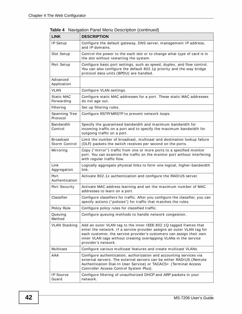
IP Setup Configure the default gateway, DNS server, management IP address, and IP domains.
Slot Setup Control the power to the each slot or to change what type of card is in the slot without restarting the system.
Port Setup Configure basic port settings, such as speed, duplex, and flow control. You can also configure the default 802.1p priority and the way bridge protocol data units (BPDU) are handled.
Advanced Application
VLAN Configure VLAN settings.
Static MAC Forwarding
Configure static MAC addresses for a port. These static MAC addresses do not age out.
Filtering Set up filtering rules.
Spanning Tree Protocol
Configure RSTP/MRSTP to prevent network loops.
Bandwidth Control
Specify the guaranteed bandwidth and maximum bandwidth for incoming traffic on a port and to specify the maximum bandwidth for outgoing traffic on a port.
Broadcast Storm Control
Limit the number of broadcast, multicast and destination lookup failure (DLF) packets the switch receives per second on the ports.
Mirroring Copy (“mirror”) traffic from one or more ports to a specified monitor port. You can examine the traffic on the monitor port without interfering with regular traffic flow.
Link Aggregation
Logically aggregate physical links to form one logical, higher-bandwidth link.
Port Authentication
Activate 802.1x authentication and configure the RADIUS server.
Port Security Activate MAC address learning and set the maximum number of MAC addresses to learn on a port.
Classifier Configure classifiers for traffic. After you configure the classifier, you can specify actions (“policies”) for traffic that matches the rules.
Policy Rule Configure policy rules for classified traffic.
Queuing Method
Configure queuing methods to handle network congestion.
VLAN Stacking Add an outer VLAN tag to the inner IEEE 802.1Q tagged frames that enter the network. If a service provider assigns an outer VLAN tag for each customer, the service provider’s customers can assign their own inner VLAN tags without creating overlapping VLANs in the service provider’s network.
Multicast Configure various multicast features and create multicast VLANs.
AAA Configure authentication, authorization and accounting services via external servers. The external servers can be either RADIUS (Remote Authentication Dial-In User Service) or TACACS+ (Terminal Access Controller Access-Control System Plus).
IP Source Guard
Configure filtering of unauthorized DHCP and ARP packets in your network.
Table 4 Navigation Panel Menu Description (continued)LINK DESCRIPTION
Chapter 4 The Web Configurator
MS-7206 User’s Guide 43
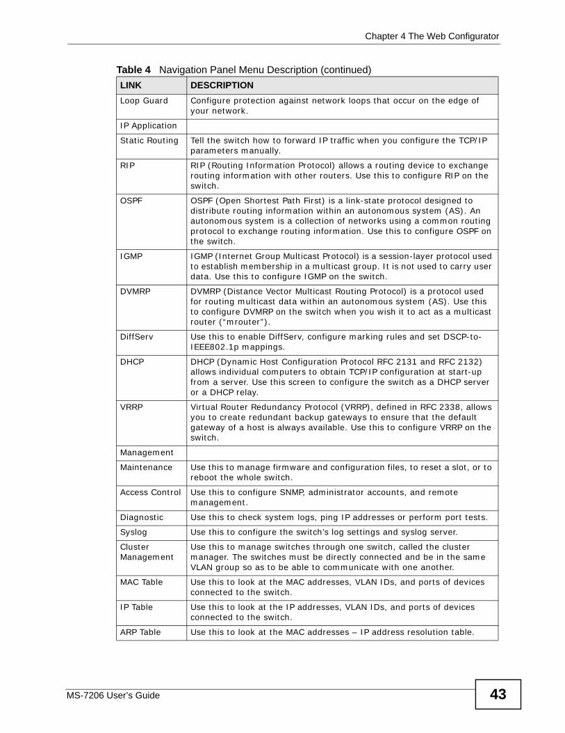
Loop Guard Configure protection against network loops that occur on the edge of your network.
IP Application
Static Routing Tell the switch how to forward IP traffic when you configure the TCP/IP parameters manually.
RIP RIP (Routing Information Protocol) allows a routing device to exchange routing information with other routers. Use this to configure RIP on the switch.
OSPF OSPF (Open Shortest Path First) is a link-state protocol designed to distribute routing information within an autonomous system (AS). An autonomous system is a collection of networks using a common routing protocol to exchange routing information. Use this to configure OSPF on the switch.
IGMP IGMP (Internet Group Multicast Protocol) is a session-layer protocol used to establish membership in a multicast group. It is not used to carry user data. Use this to configure IGMP on the switch.
DVMRP DVMRP (Distance Vector Multicast Routing Protocol) is a protocol used for routing multicast data within an autonomous system (AS). Use this to configure DVMRP on the switch when you wish it to act as a multicast router (“mrouter”).
DiffServ Use this to enable DiffServ, configure marking rules and set DSCP-to-IEEE802.1p mappings.
DHCP DHCP (Dynamic Host Configuration Protocol RFC 2131 and RFC 2132) allows individual computers to obtain TCP/IP configuration at start-up from a server. Use this screen to configure the switch as a DHCP server or a DHCP relay.
VRRP Virtual Router Redundancy Protocol (VRRP), defined in RFC 2338, allows you to create redundant backup gateways to ensure that the default gateway of a host is always available. Use this to configure VRRP on the switch.
Management
Maintenance Use this to manage firmware and configuration files, to reset a slot, or to reboot the whole switch.
Access Control Use this to configure SNMP, administrator accounts, and remote management.
Diagnostic Use this to check system logs, ping IP addresses or perform port tests.
Syslog Use this to configure the switch’s log settings and syslog server.
Cluster Management
Use this to manage switches through one switch, called the cluster manager. The switches must be directly connected and be in the same VLAN group so as to be able to communicate with one another.
MAC Table Use this to look at the MAC addresses, VLAN IDs, and ports of devices connected to the switch.
IP Table Use this to look at the IP addresses, VLAN IDs, and ports of devices connected to the switch.
ARP Table Use this to look at the MAC addresses – IP address resolution table.
Table 4 Navigation Panel Menu Description (continued)LINK DESCRIPTION
Chapter 4 The Web Configurator
MS-7206 User’s Guide44
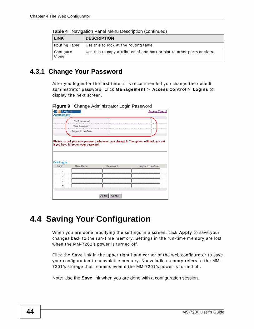
4.3.1 Change Your Password After you log in for the first time, it is recommended you change the default administrator password. Click Management > Access Control > Logins to display the next screen.
Figure 9 Change Administrator Login Password
4.4 Saving Your ConfigurationWhen you are done modifying the settings in a screen, click Apply to save your changes back to the run-time memory. Settings in the run-time memory are lost when the MM-7201’s power is turned off.
Click the Save link in the upper right hand corner of the web configurator to save your configuration to nonvolatile memory. Nonvolatile memory refers to the MM-7201’s storage that remains even if the MM-7201’s power is turned off.
Note: Use the Save link when you are done with a configuration session.
Routing Table Use this to look at the routing table.
Configure Clone
Use this to copy attributes of one port or slot to other ports or slots.
Table 4 Navigation Panel Menu Description (continued)LINK DESCRIPTION
Chapter 4 The Web Configurator
MS-7206 User’s Guide 45
4.5 Switch LockoutYou could block yourself (and all others) from using in-band-management (managing through the data ports on the interface modules) if you do one of the following:
1 Delete the management VLAN (default is VLAN 1).
2 Delete all port-based VLANs with the CPU port as a member. The “CPU port” is the management port of the switch.
3 Filter all traffic to the CPU port.
4 Disable all ports.
5 Misconfigure the text configuration file.
6 Forget the password and/or IP address.
7 Prevent all services from accessing the switch.
8 Change a service port number but forget it.
Note: Be careful not to lock yourself and others out of the switch. If you do lock yourself out, try using out-of-band management (via the management port or console port) to configure the MM-7201.
4.6 Resetting the Switch If you (and others) forget the administrator password or are no longer able to access the MM-7201 (using in-band or out-of-band management), you need to reload the factory-default configuration file.
Uploading the factory-default configuration file replaces the current configuration file with the factory-default configuration file. This means that you will lose all previous configurations and the speed of the console port will be reset to the default values in Section 2.2.2 on page 32. The password will also be reset to “1234” and the IP address to 192.168.0.1.
To upload the configuration file, do the following:
1 Connect to the console port using a computer with terminal emulation software. See Section 2.2.2 on page 32 for details.
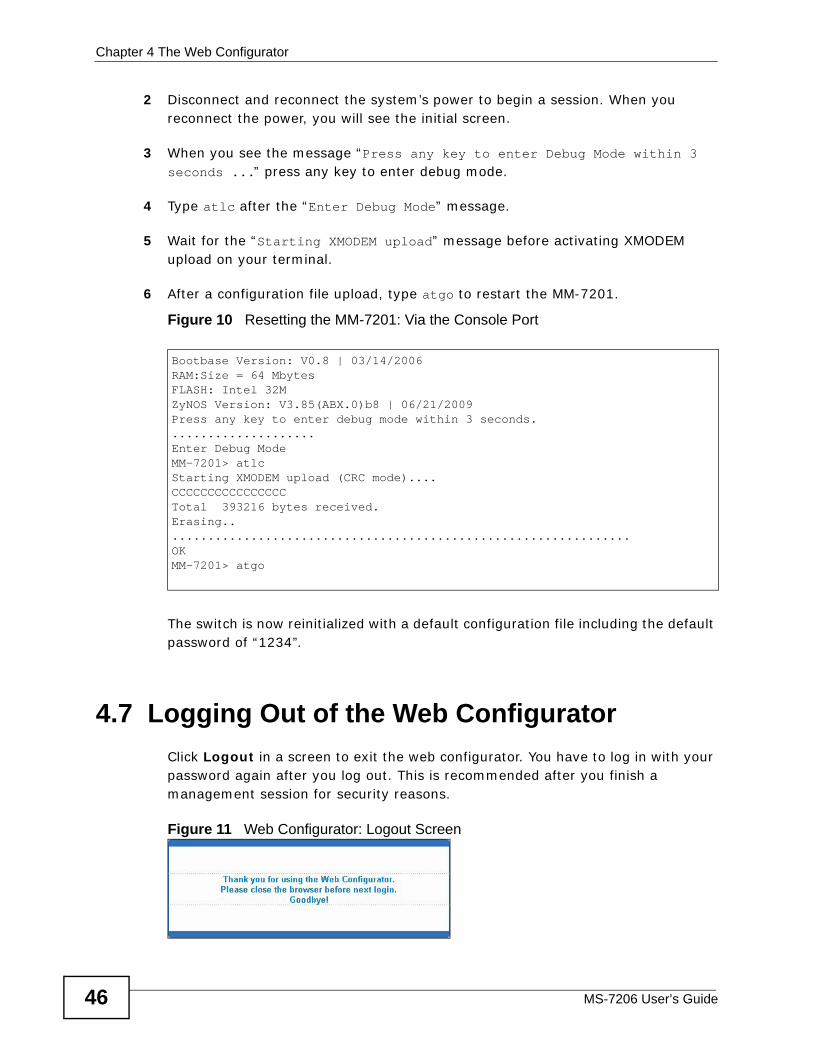
Chapter 4 The Web Configurator
MS-7206 User’s Guide46
2 Disconnect and reconnect the system’s power to begin a session. When you reconnect the power, you will see the initial screen.
3 When you see the message “Press any key to enter Debug Mode within 3 seconds ...” press any key to enter debug mode.
4 Type atlc after the “Enter Debug Mode” message.
5 Wait for the “Starting XMODEM upload” message before activating XMODEM upload on your terminal.
6 After a configuration file upload, type atgo to restart the MM-7201.
Figure 10 Resetting the MM-7201: Via the Console Port
The switch is now reinitialized with a default configuration file including the default password of “1234”.
4.7 Logging Out of the Web ConfiguratorClick Logout in a screen to exit the web configurator. You have to log in with your password again after you log out. This is recommended after you finish a management session for security reasons.
Figure 11 Web Configurator: Logout Screen
Bootbase Version: V0.8 | 03/14/2006RAM:Size = 64 MbytesFLASH: Intel 32MZyNOS Version: V3.85(ABX.0)b8 | 06/21/2009Press any key to enter debug mode within 3 seconds.....................Enter Debug ModeMM-7201> atlcStarting XMODEM upload (CRC mode)....CCCCCCCCCCCCCCCCTotal 393216 bytes received.Erasing..................................................................OKMM-7201> atgo
Chapter 4 The Web Configurator
MS-7206 User’s Guide 47
4.8 Help The web configurator’s online help has descriptions of individual screens and some supplementary information.
Click the Help link from a web configurator screen to view an online help description of that screen.

Chapter 4 The Web Configurator
MS-7206 User’s Guide48
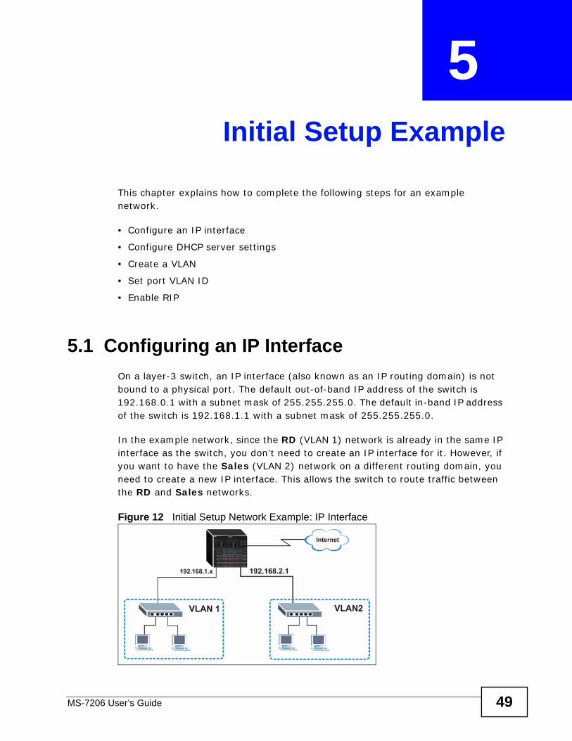
MS-7206 User’s Guide 49
CHAPTER 5 Initial Setup Example
This chapter explains how to complete the following steps for an example network.
• Configure an IP interface
• Configure DHCP server settings
• Create a VLAN
• Set port VLAN ID
• Enable RIP
5.1 Configuring an IP InterfaceOn a layer-3 switch, an IP interface (also known as an IP routing domain) is not bound to a physical port. The default out-of-band IP address of the switch is 192.168.0.1 with a subnet mask of 255.255.255.0. The default in-band IP address of the switch is 192.168.1.1 with a subnet mask of 255.255.255.0.
In the example network, since the RD (VLAN 1) network is already in the same IP interface as the switch, you don’t need to create an IP interface for it. However, if you want to have the Sales (VLAN 2) network on a different routing domain, you need to create a new IP interface. This allows the switch to route traffic between the RD and Sales networks.
Figure 12 Initial Setup Network Example: IP Interface
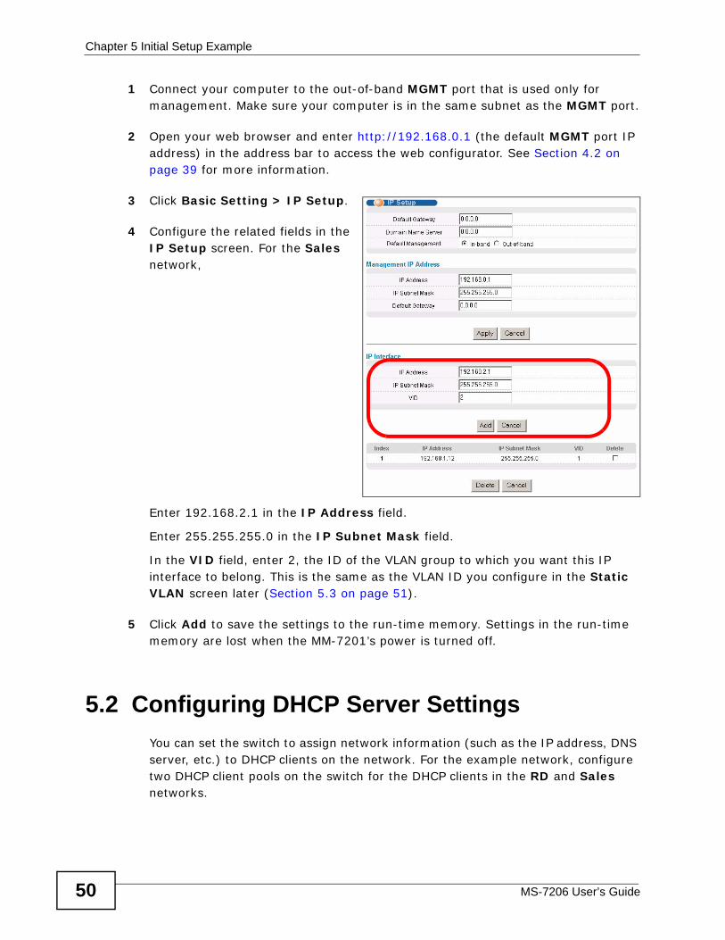
Chapter 5 Initial Setup Example
MS-7206 User’s Guide50
1 Connect your computer to the out-of-band MGMT port that is used only for management. Make sure your computer is in the same subnet as the MGMT port.
2 Open your web browser and enter http://192.168.0.1 (the default MGMT port IP address) in the address bar to access the web configurator. See Section 4.2 on page 39 for more information.
3 Click Basic Setting > IP Setup.
4 Configure the related fields in the IP Setup screen. For the Sales network,
Enter 192.168.2.1 in the IP Address field.
Enter 255.255.255.0 in the IP Subnet Mask field.
In the VID field, enter 2, the ID of the VLAN group to which you want this IP interface to belong. This is the same as the VLAN ID you configure in the Static VLAN screen later (Section 5.3 on page 51).
5 Click Add to save the settings to the run-time memory. Settings in the run-time memory are lost when the MM-7201’s power is turned off.
5.2 Configuring DHCP Server SettingsYou can set the switch to assign network information (such as the IP address, DNS server, etc.) to DHCP clients on the network. For the example network, configure two DHCP client pools on the switch for the DHCP clients in the RD and Sales networks.
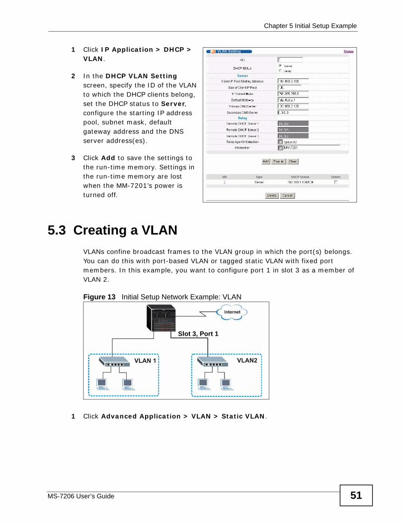
Chapter 5 Initial Setup Example
MS-7206 User’s Guide 51
1 Click IP Application > DHCP > VLAN.
2 In the DHCP VLAN Setting screen, specify the ID of the VLAN to which the DHCP clients belong, set the DHCP status to Server, configure the starting IP address pool, subnet mask, default gateway address and the DNS server address(es).
3 Click Add to save the settings to the run-time memory. Settings in the run-time memory are lost when the MM-7201’s power is turned off.
5.3 Creating a VLAN VLANs confine broadcast frames to the VLAN group in which the port(s) belongs. You can do this with port-based VLAN or tagged static VLAN with fixed port members. In this example, you want to configure port 1 in slot 3 as a member of VLAN 2.
Figure 13 Initial Setup Network Example: VLAN
1 Click Advanced Application > VLAN > Static VLAN.
Slot 3, Port 1
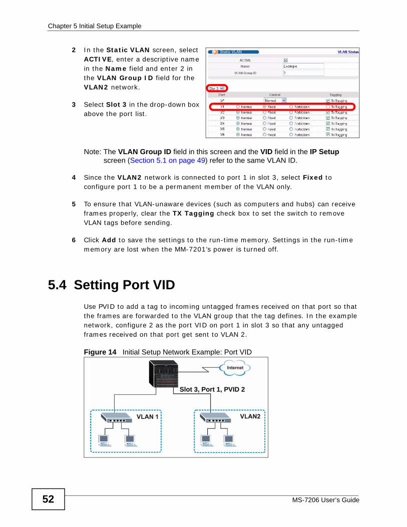
Chapter 5 Initial Setup Example
MS-7206 User’s Guide52
2 In the Static VLAN screen, select ACTIVE, enter a descriptive name in the Name field and enter 2 in the VLAN Group ID field for the VLAN2 network.
3 Select Slot 3 in the drop-down box above the port list.
Note: The VLAN Group ID field in this screen and the VID field in the IP Setup screen (Section 5.1 on page 49) refer to the same VLAN ID.
4 Since the VLAN2 network is connected to port 1 in slot 3, select Fixed to configure port 1 to be a permanent member of the VLAN only.
5 To ensure that VLAN-unaware devices (such as computers and hubs) can receive frames properly, clear the TX Tagging check box to set the switch to remove VLAN tags before sending.
6 Click Add to save the settings to the run-time memory. Settings in the run-time memory are lost when the MM-7201’s power is turned off.
5.4 Setting Port VIDUse PVID to add a tag to incoming untagged frames received on that port so that the frames are forwarded to the VLAN group that the tag defines. In the example network, configure 2 as the port VID on port 1 in slot 3 so that any untagged frames received on that port get sent to VLAN 2.
Figure 14 Initial Setup Network Example: Port VID
Slot 3, Port 1, PVID 2
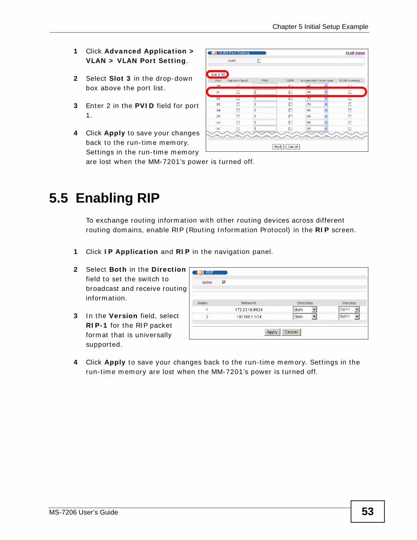
Chapter 5 Initial Setup Example
MS-7206 User’s Guide 53
1 Click Advanced Application > VLAN > VLAN Port Setting.
2 Select Slot 3 in the drop-down box above the port list.
3 Enter 2 in the PVID field for port 1.
4 Click Apply to save your changes back to the run-time memory. Settings in the run-time memory are lost when the MM-7201’s power is turned off.
5.5 Enabling RIPTo exchange routing information with other routing devices across different routing domains, enable RIP (Routing Information Protocol) in the RIP screen.
1 Click IP Application and RIP in the navigation panel.
2 Select Both in the Direction field to set the switch to broadcast and receive routing information.
3 In the Version field, select RIP-1 for the RIP packet format that is universally supported.
4 Click Apply to save your changes back to the run-time memory. Settings in the run-time memory are lost when the MM-7201’s power is turned off.

Chapter 5 Initial Setup Example
MS-7206 User’s Guide54
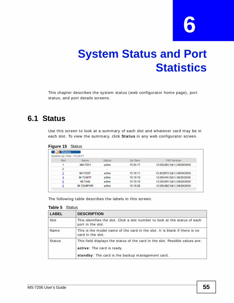
MS-7206 User’s Guide 55
CHAPTER 6 System Status and Port
Statistics
This chapter describes the system status (web configurator home page), port status, and port details screens.
6.1 StatusUse this screen to look at a summary of each slot and whatever card may be in each slot. To view the summary, click Status in any web configurator screen.
Figure 15 Status
The following table describes the labels in this screen.
Table 5 StatusLABEL DESCRIPTIONSlot This identifies the slot. Click a slot number to look at the status of each
port in the slot.
Name This is the model name of the card in the slot. It is blank if there is no card in the slot.
Status This field displays the status of the card in the slot. Possible values are:
active: The card is ready.
standby: The card is the backup management card.
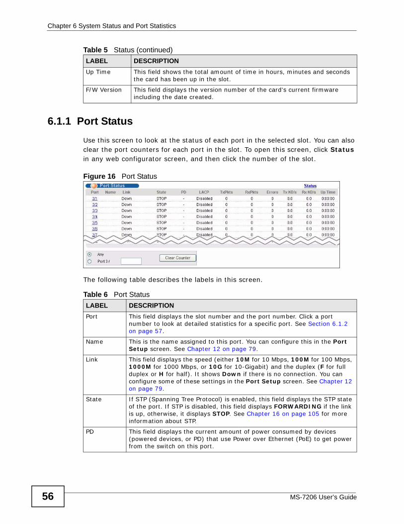
Chapter 6 System Status and Port Statistics
MS-7206 User’s Guide56
6.1.1 Port StatusUse this screen to look at the status of each port in the selected slot. You can also clear the port counters for each port in the slot. To open this screen, click Status in any web configurator screen, and then click the number of the slot.
Figure 16 Port Status
The following table describes the labels in this screen.
Up Time This field shows the total amount of time in hours, minutes and seconds the card has been up in the slot.
F/W Version This field displays the version number of the card's current firmware including the date created.
Table 5 Status (continued)LABEL DESCRIPTION
Table 6 Port Status LABEL DESCRIPTIONPort This field displays the slot number and the port number. Click a port
number to look at detailed statistics for a specific port. See Section 6.1.2 on page 57.
Name This is the name assigned to this port. You can configure this in the Port Setup screen. See Chapter 12 on page 79.
Link This field displays the speed (either 10M for 10 Mbps, 100M for 100 Mbps, 1000M for 1000 Mbps, or 10G for 10-Gigabit) and the duplex (F for full duplex or H for half). It shows Down if there is no connection. You can configure some of these settings in the Port Setup screen. See Chapter 12 on page 79.
State If STP (Spanning Tree Protocol) is enabled, this field displays the STP state of the port. If STP is disabled, this field displays FORWARDING if the link is up, otherwise, it displays STOP. See Chapter 16 on page 105 for more information about STP.
PD This field displays the current amount of power consumed by devices (powered devices, or PD) that use Power over Ethernet (PoE) to get power from the switch on this port.
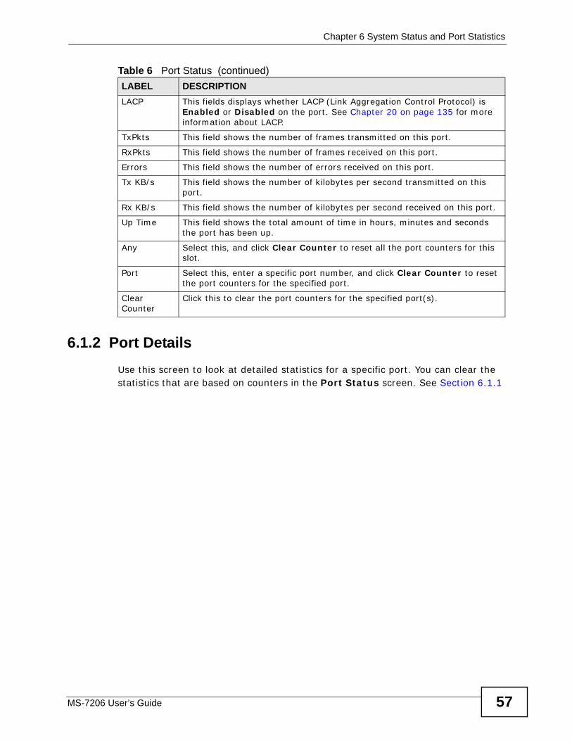
Chapter 6 System Status and Port Statistics
MS-7206 User’s Guide 57
6.1.2 Port DetailsUse this screen to look at detailed statistics for a specific port. You can clear the statistics that are based on counters in the Port Status screen. See Section 6.1.1
LACP This fields displays whether LACP (Link Aggregation Control Protocol) is Enabled or Disabled on the port. See Chapter 20 on page 135 for more information about LACP.
TxPkts This field shows the number of frames transmitted on this port.
RxPkts This field shows the number of frames received on this port.
Errors This field shows the number of errors received on this port.
Tx KB/s This field shows the number of kilobytes per second transmitted on this port.
Rx KB/s This field shows the number of kilobytes per second received on this port.
Up Time This field shows the total amount of time in hours, minutes and seconds the port has been up.
Any Select this, and click Clear Counter to reset all the port counters for this slot.
Port Select this, enter a specific port number, and click Clear Counter to reset the port counters for the specified port.
Clear Counter
Click this to clear the port counters for the specified port(s).
Table 6 Port Status (continued)LABEL DESCRIPTION
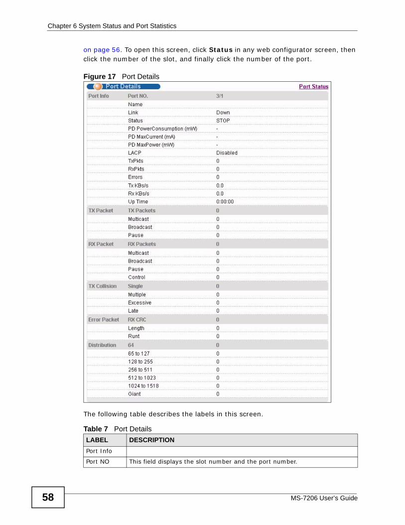
Chapter 6 System Status and Port Statistics
MS-7206 User’s Guide58
on page 56. To open this screen, click Status in any web configurator screen, then click the number of the slot, and finally click the number of the port.
Figure 17 Port Details
The following table describes the labels in this screen.
Table 7 Port DetailsLABEL DESCRIPTIONPort Info
Port NO This field displays the slot number and the port number.
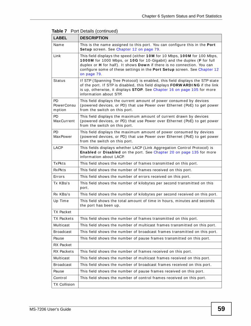
Chapter 6 System Status and Port Statistics
MS-7206 User’s Guide 59
Name This is the name assigned to this port. You can configure this in the Port Setup screen. See Chapter 12 on page 79.
Link This field displays the speed (either 10M for 10 Mbps, 100M for 100 Mbps, 1000M for 1000 Mbps, or 10G for 10-Gigabit) and the duplex (F for full duplex or H for half). It shows Down if there is no connection. You can configure some of these settings in the Port Setup screen. See Chapter 12 on page 79.
Status If STP (Spanning Tree Protocol) is enabled, this field displays the STP state of the port. If STP is disabled, this field displays FORWARDING if the link is up, otherwise, it displays STOP. See Chapter 16 on page 105 for more information about STP.
PD PowerConsumption
This field displays the current amount of power consumed by devices (powered devices, or PD) that use Power over Ethernet (PoE) to get power from the switch on this port.
PD MaxCurrent
This field displays the maximum amount of current drawn by devices (powered devices, or PD) that use Power over Ethernet (PoE) to get power from the switch on this port.
PD MaxPower
This field displays the maximum amount of power consumed by devices (powered devices, or PD) that use Power over Ethernet (PoE) to get power from the switch on this port.
LACP This fields displays whether LACP (Link Aggregation Control Protocol) is Enabled or Disabled on the port. See Chapter 20 on page 135 for more information about LACP.
TxPkts This field shows the number of frames transmitted on this port.
RxPkts This field shows the number of frames received on this port.
Errors This field shows the number of errors received on this port.
Tx KBs/s This field shows the number of kilobytes per second transmitted on this port.
Rx KBs/s This field shows the number of kilobytes per second received on this port.
Up Time This field shows the total amount of time in hours, minutes and seconds the port has been up.
TX Packet
TX Packets This field shows the number of frames transmitted on this port.
Multicast This field shows the number of multicast frames transmitted on this port.
Broadcast This field shows the number of broadcast frames transmitted on this port.
Pause This field shows the number of pause frames transmitted on this port.
RX Packet
RX Packets This field shows the number of frames received on this port.
Multicast This field shows the number of multicast frames received on this port.
Broadcast This field shows the number of broadcast frames received on this port.
Pause This field shows the number of pause frames received on this port.
Control This field shows the number of control frames received on this port.
TX Collision
Table 7 Port Details (continued)LABEL DESCRIPTION
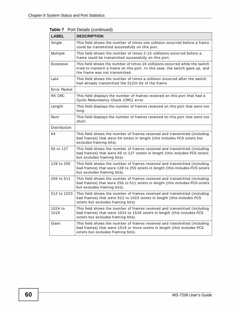
Chapter 6 System Status and Port Statistics
MS-7206 User’s Guide60
Single This field shows the number of times one collision occurred before a frame could be transmitted successfully on this port.
Multiple This field shows the number of times 2-15 collisions occurred before a frame could be transmitted successfully on this port.
Excessive This field shows the number of times 16 collisions occurred while the switch tried to transmit a frame on this port. In this case, the switch gave up, and the frame was not transmitted.
Late This field shows the number of times a collision occurred after the switch had already transmitted the 512th bit of the frame.
Error Packet
RX CRC This field displays the number of frames received on this port that had a Cyclic Redundancy Check (CRC) error.
Length This field displays the number of frames received on this port that were too long.
Runt This field displays the number of frames received on this port that were too short.
Distribution
64 This field shows the number of frames received and transmitted (including bad frames) that were 64 octets in length (this includes FCS octets but excludes framing bits).
65 to 127 This field shows the number of frames received and transmitted (including bad frames) that were 65 to 127 octets in length (this includes FCS octets but excludes framing bits).
128 to 255 This field shows the number of frames received and transmitted (including bad frames) that were 128 to 255 octets in length (this includes FCS octets but excludes framing bits).
256 to 511 This field shows the number of frames received and transmitted (including bad frames) that were 256 to 511 octets in length (this includes FCS octets but excludes framing bits).
512 to 1023 This field shows the number of frames received and transmitted (including bad frames) that were 512 to 1023 octets in length (this includes FCS octets but excludes framing bits).
1024 to 1518
This field shows the number of frames received and transmitted (including bad frames) that were 1024 to 1518 octets in length (this includes FCS octets but excludes framing bits).
Giant This field shows the number of frames received and transmitted (including bad frames) that were 1519 or more octets in length (this includes FCS octets but excludes framing bits).
Table 7 Port Details (continued)LABEL DESCRIPTION
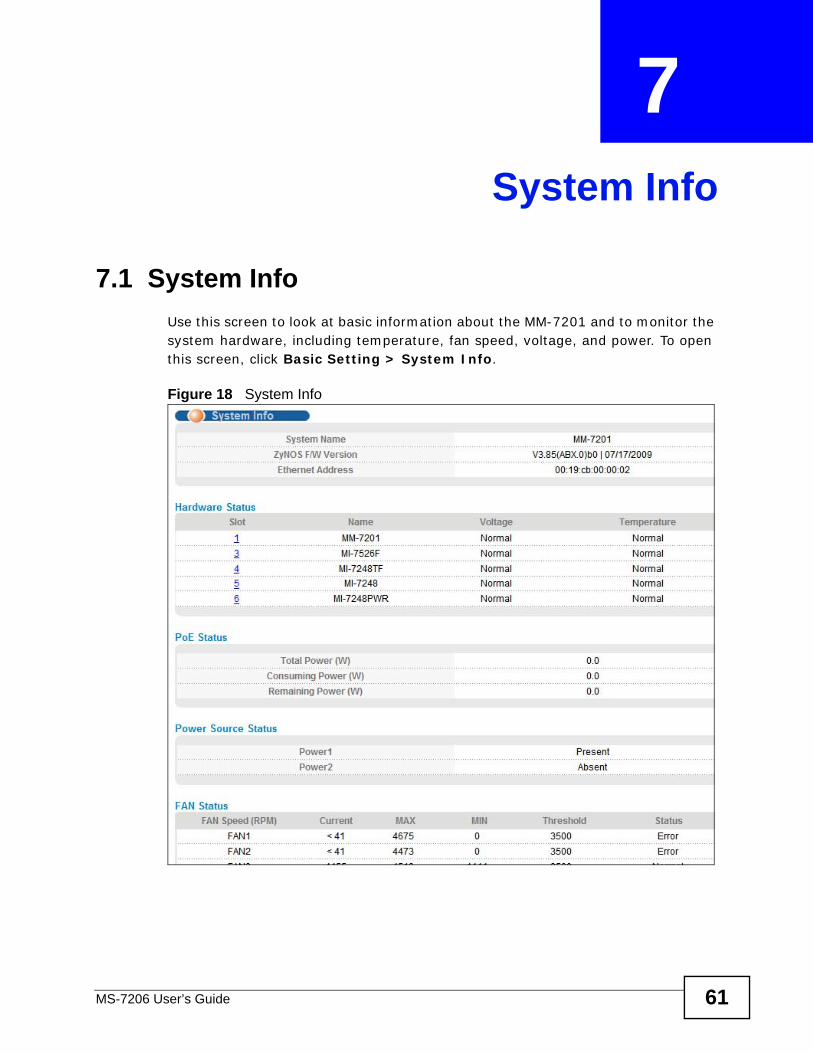
MS-7206 User’s Guide 61
CHAPTER 7 System Info
7.1 System InfoUse this screen to look at basic information about the MM-7201 and to monitor the system hardware, including temperature, fan speed, voltage, and power. To open this screen, click Basic Setting > System Info.
Figure 18 System Info

Chapter 7 System Info
MS-7206 User’s Guide62
The following table describes the labels in this screen.
Table 8 System Info LABEL DESCRIPTIONSystem Name
This field displays the descriptive name of the MM-7201 for identification purposes. Click Basic Setting > General Setup to change this. See Chapter 8 on page 65.
ZyNOS F/W Version
This field displays the version number of the MM-7201's current firmware including the date created. Click Management > Maintenance > Firmware Upgrade to change this. See Chapter 39 on page 293.
Ethernet Address
This field displays the Ethernet MAC (Media Access Control) address of the MS-7206 system. The MS-7206 system copies the MAC address from the active management card when the MS-7206 system starts up. The MS-7206 system keeps using this MAC address, even if the standby management card takes over, until the system starts up again.
Hardware Status
Slot This field displays the slots that have a card installed in them. Click a slot number to look at more detail about the card’s hardware. See Section 7.1.1 on page 63.
Name This field displays the type of card in the slot.
Voltage This field displays the voltage status in the card.
Normal: The voltage is within allowable range.
Error: The voltage is outside the allowable range at one or more sensors.
Temperature This field displays the temperature status in the card.
Normal: The temperature is below the threshold.
Error: The temperature is above the threshold at one or more sensors.
PoE Status
Total Power (W)
This field displays the total amount of power available from a Power over Ethernet (PoE) injector.
Consuming Power (W)
This field displays the amount of power from a PoE injector the system is using.
Remaining Power (W)
This field displays the amount of power from a PoE injector the system is not using.
Power Source Status
Power1
Power2
This field displays the status of each power module in the system.
Present: There is a power module in this slot, and it is working properly.
Absent: There is no power module in this slot, or the power module is not working properly.
FAN Status
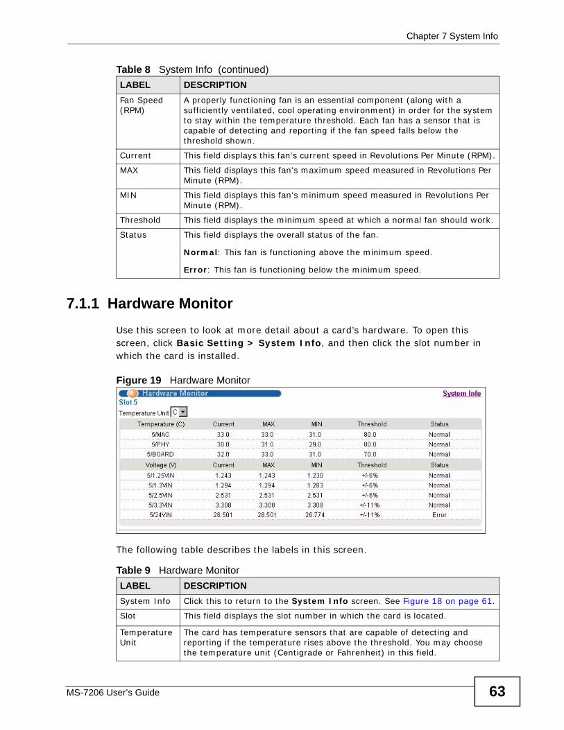
Chapter 7 System Info
MS-7206 User’s Guide 63
7.1.1 Hardware MonitorUse this screen to look at more detail about a card’s hardware. To open this screen, click Basic Setting > System Info, and then click the slot number in which the card is installed.
Figure 19 Hardware Monitor
The following table describes the labels in this screen.
Fan Speed (RPM)
A properly functioning fan is an essential component (along with a sufficiently ventilated, cool operating environment) in order for the system to stay within the temperature threshold. Each fan has a sensor that is capable of detecting and reporting if the fan speed falls below the threshold shown.
Current This field displays this fan's current speed in Revolutions Per Minute (RPM).
MAX This field displays this fan's maximum speed measured in Revolutions Per Minute (RPM).
MIN This field displays this fan's minimum speed measured in Revolutions Per Minute (RPM).
Threshold This field displays the minimum speed at which a normal fan should work.
Status This field displays the overall status of the fan.
Normal: This fan is functioning above the minimum speed.
Error: This fan is functioning below the minimum speed.
Table 8 System Info (continued)LABEL DESCRIPTION
Table 9 Hardware Monitor LABEL DESCRIPTIONSystem Info Click this to return to the System Info screen. See Figure 18 on page 61.
Slot This field displays the slot number in which the card is located.
Temperature Unit
The card has temperature sensors that are capable of detecting and reporting if the temperature rises above the threshold. You may choose the temperature unit (Centigrade or Fahrenheit) in this field.
Chapter 7 System Info
MS-7206 User’s Guide64
Temperature The number is the slot number in which the card is located. MAC, PHY and BOARD refer to the location of the temperature sensors on the card’s printed circuit board.
Current This shows the current temperature in degrees at this sensor.
MAX This field displays the maximum temperature measured at this sensor.
MIN This field displays the minimum temperature measured at this sensor.
Threshold This field displays the upper temperature limit at this sensor.
Status This field displays the status of each sensor.
Normal: The temperature is below the threshold.
Error: The temperature is above the threshold.
Voltage(V) The number is the slot number in which the card is located. The power supply for each voltage has a sensor that is capable of detecting and reporting if the voltage falls out of the tolerance range.
Current This is the current voltage reading.
MAX This field displays the maximum voltage measured at this point.
MIN This field displays the minimum voltage measured at this point.
Threshold This field displays the percentage tolerance of the voltage with which the card still works.
Status This field displays the status of each sensor.
Normal: The voltage is within allowable range.
Error: The voltage is outside the allowable range at one or more sensors.
Table 9 Hardware Monitor (continued)LABEL DESCRIPTION
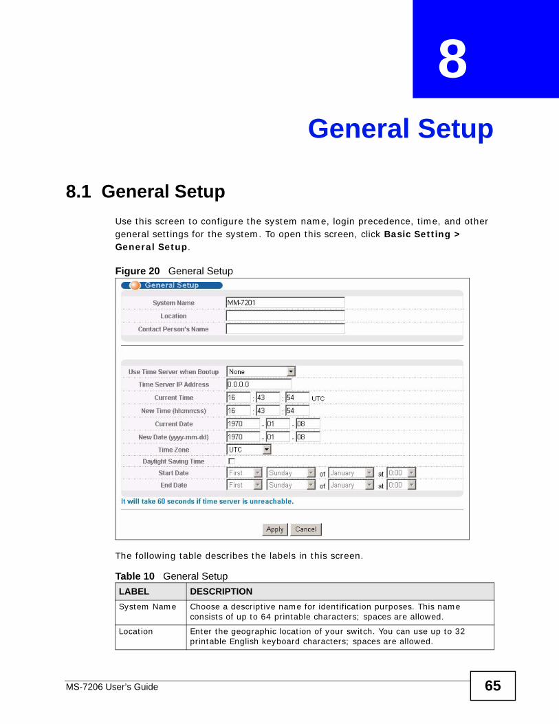
MS-7206 User’s Guide 65
CHAPTER 8 General Setup
8.1 General Setup Use this screen to configure the system name, login precedence, time, and other general settings for the system. To open this screen, click Basic Setting > General Setup.
Figure 20 General Setup
The following table describes the labels in this screen.
Table 10 General Setup LABEL DESCRIPTIONSystem Name Choose a descriptive name for identification purposes. This name
consists of up to 64 printable characters; spaces are allowed.
Location Enter the geographic location of your switch. You can use up to 32 printable English keyboard characters; spaces are allowed.
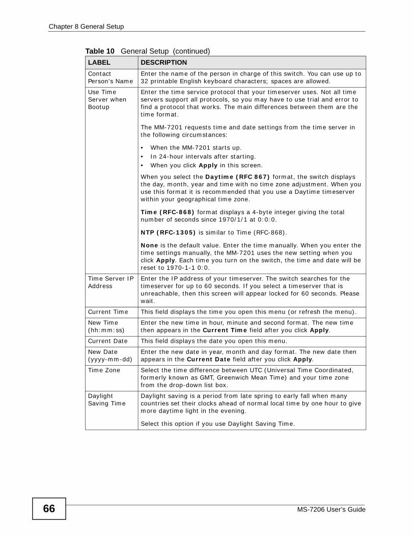
Chapter 8 General Setup
MS-7206 User’s Guide66
Contact Person's Name
Enter the name of the person in charge of this switch. You can use up to 32 printable English keyboard characters; spaces are allowed.
Use Time Server when Bootup
Enter the time service protocol that your timeserver uses. Not all time servers support all protocols, so you may have to use trial and error to find a protocol that works. The main differences between them are the time format.
The MM-7201 requests time and date settings from the time server in the following circumstances:
• When the MM-7201 starts up.• In 24-hour intervals after starting.• When you click Apply in this screen.
When you select the Daytime (RFC 867) format, the switch displays the day, month, year and time with no time zone adjustment. When you use this format it is recommended that you use a Daytime timeserver within your geographical time zone.
Time (RFC-868) format displays a 4-byte integer giving the total number of seconds since 1970/1/1 at 0:0:0.
NTP (RFC-1305) is similar to Time (RFC-868).
None is the default value. Enter the time manually. When you enter the time settings manually, the MM-7201 uses the new setting when you click Apply. Each time you turn on the switch, the time and date will be reset to 1970-1-1 0:0.
Time Server IP Address
Enter the IP address of your timeserver. The switch searches for the timeserver for up to 60 seconds. If you select a timeserver that is unreachable, then this screen will appear locked for 60 seconds. Please wait.
Current Time This field displays the time you open this menu (or refresh the menu).
New Time (hh:mm:ss)
Enter the new time in hour, minute and second format. The new time then appears in the Current Time field after you click Apply.
Current Date This field displays the date you open this menu.
New Date (yyyy-mm-dd)
Enter the new date in year, month and day format. The new date then appears in the Current Date field after you click Apply.
Time Zone Select the time difference between UTC (Universal Time Coordinated, formerly known as GMT, Greenwich Mean Time) and your time zone from the drop-down list box.
Daylight Saving Time
Daylight saving is a period from late spring to early fall when many countries set their clocks ahead of normal local time by one hour to give more daytime light in the evening.
Select this option if you use Daylight Saving Time.
Table 10 General Setup (continued)LABEL DESCRIPTION
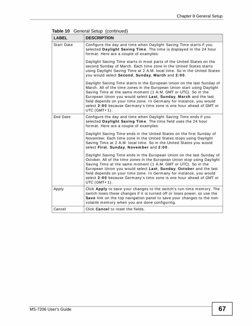
Chapter 8 General Setup
MS-7206 User’s Guide 67
Start Date Configure the day and time when Daylight Saving Time starts if you selected Daylight Saving Time. The time is displayed in the 24 hour format. Here are a couple of examples:
Daylight Saving Time starts in most parts of the United States on the second Sunday of March. Each time zone in the United States starts using Daylight Saving Time at 2 A.M. local time. So in the United States you would select Second, Sunday, March and 2:00.
Daylight Saving Time starts in the European Union on the last Sunday of March. All of the time zones in the European Union start using Daylight Saving Time at the same moment (1 A.M. GMT or UTC). So in the European Union you would select Last, Sunday, March and the last field depends on your time zone. In Germany for instance, you would select 2:00 because Germany's time zone is one hour ahead of GMT or UTC (GMT+1).
End Date Configure the day and time when Daylight Saving Time ends if you selected Daylight Saving Time. The time field uses the 24 hour format. Here are a couple of examples:
Daylight Saving Time ends in the United States on the first Sunday of November. Each time zone in the United States stops using Daylight Saving Time at 2 A.M. local time. So in the United States you would select First, Sunday, November and 2:00.
Daylight Saving Time ends in the European Union on the last Sunday of October. All of the time zones in the European Union stop using Daylight Saving Time at the same moment (1 A.M. GMT or UTC). So in the European Union you would select Last, Sunday, October and the last field depends on your time zone. In Germany for instance, you would select 2:00 because Germany's time zone is one hour ahead of GMT or UTC (GMT+1).
Apply Click Apply to save your changes to the switch’s run-time memory. The switch loses these changes if it is turned off or loses power, so use the Save link on the top navigation panel to save your changes to the non-volatile memory when you are done configuring.
Cancel Click Cancel to reset the fields.
Table 10 General Setup (continued)LABEL DESCRIPTION

Chapter 8 General Setup
MS-7206 User’s Guide68
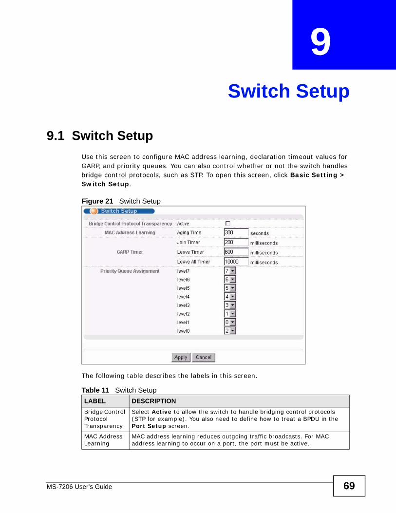
MS-7206 User’s Guide 69
CHAPTER 9 Switch Setup
9.1 Switch SetupUse this screen to configure MAC address learning, declaration timeout values for GARP, and priority queues. You can also control whether or not the switch handles bridge control protocols, such as STP. To open this screen, click Basic Setting > Switch Setup.
Figure 21 Switch Setup
The following table describes the labels in this screen.
Table 11 Switch Setup LABEL DESCRIPTIONBridge Control Protocol Transparency
Select Active to allow the switch to handle bridging control protocols (STP for example). You also need to define how to treat a BPDU in the Port Setup screen.
MAC Address Learning
MAC address learning reduces outgoing traffic broadcasts. For MAC address learning to occur on a port, the port must be active.
Chapter 9 Switch Setup
MS-7206 User’s Guide70
Aging Time Enter a time from 10 to 3000 seconds. This is how long all dynamically learned MAC addresses remain in the MAC address table before they age out (and must be relearned).
GARP Timer: Switches join VLANs by making a declaration. A declaration is made by issuing a Join message using GARP. Declarations are withdrawn by issuing a Leave message. A Leave All message terminates all registrations. GARP timers set declaration timeout values. See Chapter 13 on page 85 for more information.
Join Timer Join Timer sets the duration of the Join Period timer for GVRP in milliseconds. Each port has a Join Period timer. The allowed Join Time range is between 100 and 65535 milliseconds; the default is 200 milliseconds. See the chapter on VLAN setup for more background information.
Leave Timer Leave Time sets the duration of the Leave Period timer for GVRP in milliseconds. Each port has a single Leave Period timer. Leave Time must be two times larger than Join Timer; the default is 600 milliseconds.
Leave All Timer
Leave All Timer sets the duration of the Leave All Period timer for GVRP in milliseconds. Each port has a single Leave All Period timer. Leave All Timer must be larger than Leave Timer.
Priority Queue Assignment
Use this section to configure the priority level-to-physical queue mapping.
IEEE 802.1p defines up to eight separate traffic types by inserting a tag into a MAC-layer frame that contains bits to define class of service. Frames without an explicit priority tag are given the default priority of the ingress port. See Chapter 12 on page 79 to configure the default priority.
The switch has eight physical queues that you can map to the 8 priority levels. On the switch, traffic assigned to higher index queues gets through faster while traffic in lower index queues is dropped if the network is congested.
Priority Level The following descriptions are based on the traffic types defined in the IEEE 802.1d standard (which incorporates the 802.1p).
level7 Typically used for network control traffic such as router configuration messages.
level6 Typically used for voice traffic that is especially sensitive to jitter (jitter is the variations in delay).
level5 Typically used for video that consumes high bandwidth and is sensitive to jitter.
level4 Typically used for controlled load, latency-sensitive traffic such as SNA (Systems Network Architecture) transactions.
level3 Typically used for “excellent effort” or better than best effort and would include important business traffic that can tolerate some delay.
level2 This is for “spare bandwidth”.
level1 This is typically used for non-critical “background” traffic such as bulk transfers that are allowed but that should not affect other applications and users.
level0 Typically used for best-effort traffic.
Table 11 Switch Setup (continued)LABEL DESCRIPTION
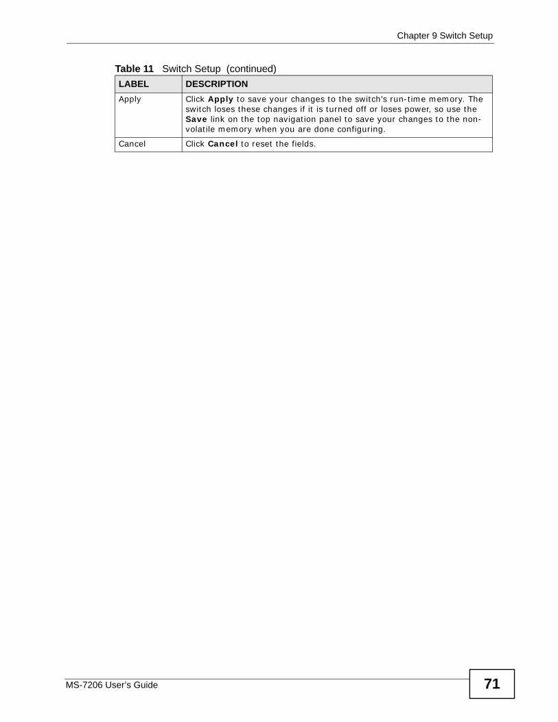
Chapter 9 Switch Setup
MS-7206 User’s Guide 71
Apply Click Apply to save your changes to the switch’s run-time memory. The switch loses these changes if it is turned off or loses power, so use the Save link on the top navigation panel to save your changes to the non-volatile memory when you are done configuring.
Cancel Click Cancel to reset the fields.
Table 11 Switch Setup (continued)LABEL DESCRIPTION

Chapter 9 Switch Setup
MS-7206 User’s Guide72
MS-7206 User’s Guide 73
CHAPTER 10 IP Setup
This chapter introduces IP interfaces and then describes the IP Setup screen.
10.1 IP InterfacesThe switch needs an IP address for it to be managed over the network. The factory default IP address is 192.168.0.1. The subnet mask specifies the network number portion of an IP address. The factory default subnet mask is 255.255.255.0.
On the switch, as a layer-3 device, an IP address is not bound to any physical ports. Since each IP address on the switch must be in a separate subnet, the configured IP address is also known as IP interface (or routing domain). In addition, this allows routing between subnets based on the IP address without additional routers.
You can configure multiple routing domains on the same VLAN as long as the IP address ranges for the domains do not overlap. To change the IP address of the switch in a routing domain, simply add a new routing domain entry with a different IP address in the same subnet.
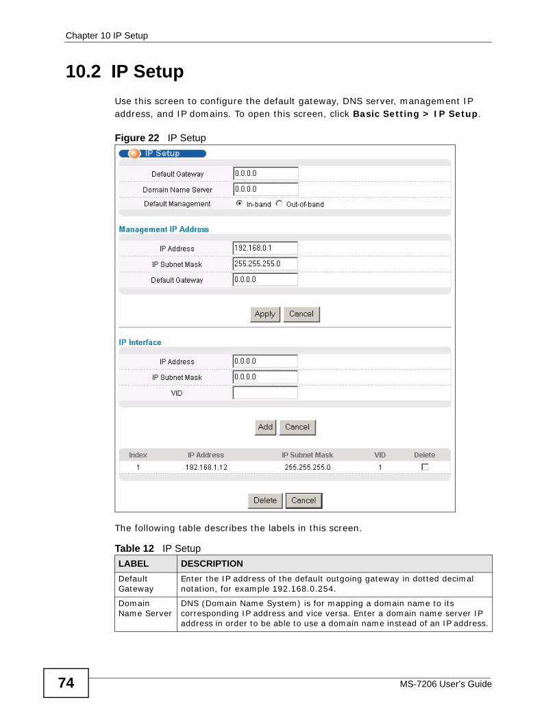
Chapter 10 IP Setup
MS-7206 User’s Guide74
10.2 IP SetupUse this screen to configure the default gateway, DNS server, management IP address, and IP domains. To open this screen, click Basic Setting > IP Setup.
Figure 22 IP Setup
The following table describes the labels in this screen.
Table 12 IP Setup LABEL DESCRIPTIONDefault Gateway
Enter the IP address of the default outgoing gateway in dotted decimal notation, for example 192.168.0.254.
Domain Name Server
DNS (Domain Name System) is for mapping a domain name to its corresponding IP address and vice versa. Enter a domain name server IP address in order to be able to use a domain name instead of an IP address.
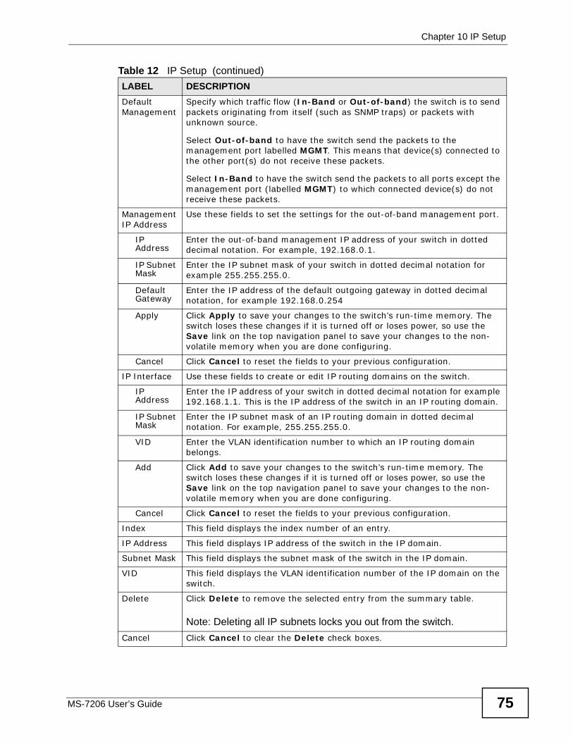
Chapter 10 IP Setup
MS-7206 User’s Guide 75
Default Management
Specify which traffic flow (In-Band or Out-of-band) the switch is to send packets originating from itself (such as SNMP traps) or packets with unknown source.
Select Out-of-band to have the switch send the packets to the management port labelled MGMT. This means that device(s) connected to the other port(s) do not receive these packets.
Select In-Band to have the switch send the packets to all ports except the management port (labelled MGMT) to which connected device(s) do not receive these packets.
Management IP Address
Use these fields to set the settings for the out-of-band management port.
IP Address
Enter the out-of-band management IP address of your switch in dotted decimal notation. For example, 192.168.0.1.
IP Subnet Mask
Enter the IP subnet mask of your switch in dotted decimal notation for example 255.255.255.0.
Default Gateway
Enter the IP address of the default outgoing gateway in dotted decimal notation, for example 192.168.0.254
Apply Click Apply to save your changes to the switch’s run-time memory. The switch loses these changes if it is turned off or loses power, so use the Save link on the top navigation panel to save your changes to the non-volatile memory when you are done configuring.
Cancel Click Cancel to reset the fields to your previous configuration.
IP Interface Use these fields to create or edit IP routing domains on the switch.
IP Address
Enter the IP address of your switch in dotted decimal notation for example 192.168.1.1. This is the IP address of the switch in an IP routing domain.
IP Subnet Mask
Enter the IP subnet mask of an IP routing domain in dotted decimal notation. For example, 255.255.255.0.
VID Enter the VLAN identification number to which an IP routing domain belongs.
Add Click Add to save your changes to the switch’s run-time memory. The switch loses these changes if it is turned off or loses power, so use the Save link on the top navigation panel to save your changes to the non-volatile memory when you are done configuring.
Cancel Click Cancel to reset the fields to your previous configuration.
Index This field displays the index number of an entry.
IP Address This field displays IP address of the switch in the IP domain.
Subnet Mask This field displays the subnet mask of the switch in the IP domain.
VID This field displays the VLAN identification number of the IP domain on the switch.
Delete Click Delete to remove the selected entry from the summary table.
Note: Deleting all IP subnets locks you out from the switch.Cancel Click Cancel to clear the Delete check boxes.
Table 12 IP Setup (continued)LABEL DESCRIPTION

Chapter 10 IP Setup
MS-7206 User’s Guide76
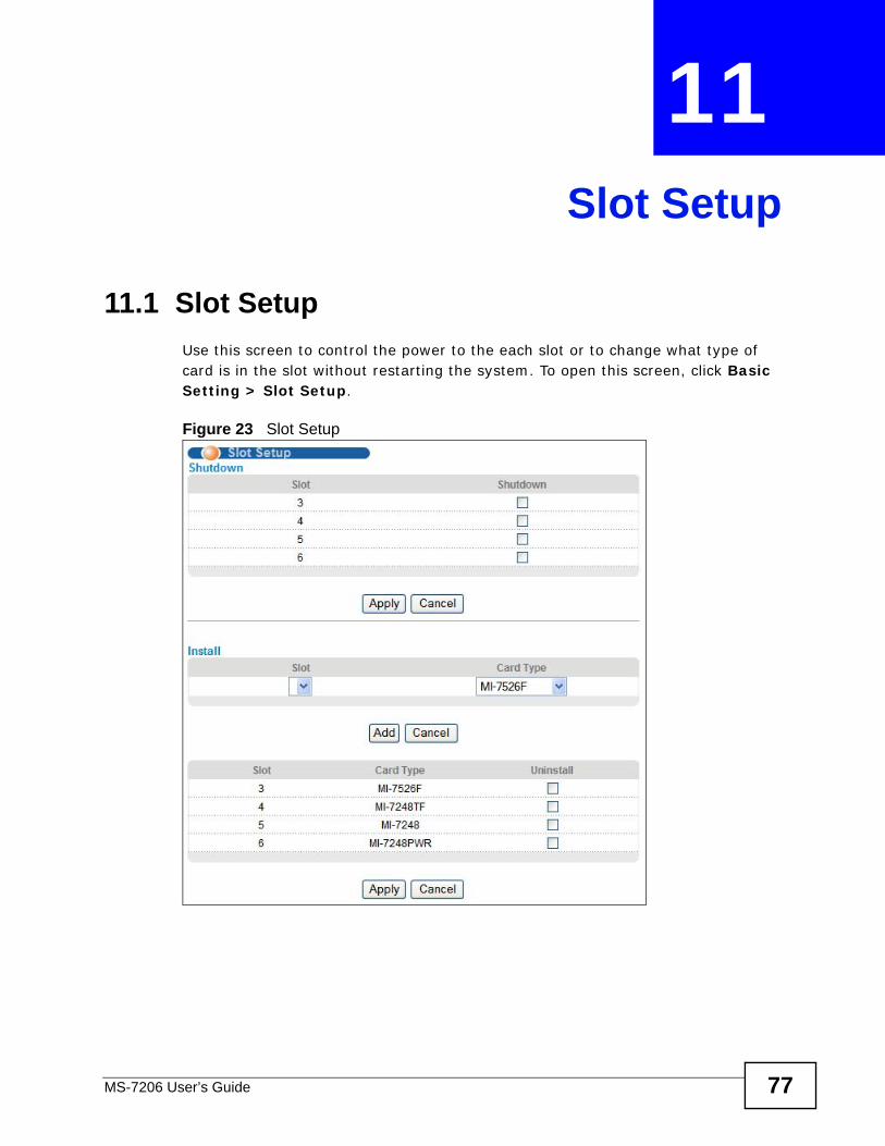
MS-7206 User’s Guide 77
CHAPTER 11 Slot Setup
11.1 Slot SetupUse this screen to control the power to the each slot or to change what type of card is in the slot without restarting the system. To open this screen, click Basic Setting > Slot Setup.
Figure 23 Slot Setup
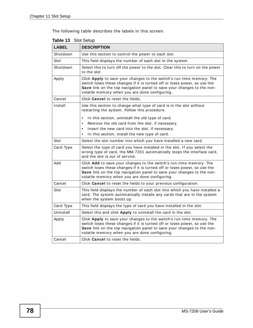
Chapter 11 Slot Setup
MS-7206 User’s Guide78
The following table describes the labels in this screen.
Table 13 Slot SetupLABEL DESCRIPTIONShutdown Use this section to control the power to each slot.
Slot This field displays the number of each slot in the system.
Shutdown Select this to turn off the power to the slot. Clear this to turn on the power to the slot.
Apply Click Apply to save your changes to the switch’s run-time memory. The switch loses these changes if it is turned off or loses power, so use the Save link on the top navigation panel to save your changes to the non-volatile memory when you are done configuring.
Cancel Click Cancel to reset the fields.
Install Use this section to change what type of card is in the slot without restarting the system. Follow this procedure.
• In this section, uninstall the old type of card.• Remove the old card from the slot, if necessary.• Insert the new card into the slot, if necessary.• In this section, install the new type of card.
Slot Select the slot number into which you have installed a new card.
Card Type Select the type of card you have installed in the slot. If you select the wrong type of card, the MM-7201 automatically stops the interface card, and the slot is out of service.
Add Click Add to save your changes to the switch’s run-time memory. The switch loses these changes if it is turned off or loses power, so use the Save link on the top navigation panel to save your changes to the non-volatile memory when you are done configuring.
Cancel Click Cancel to reset the fields to your previous configuration.
Slot This field displays the number of each slot into which you have installed a card. The system automatically installs any cards that are in the system when the system boots up.
Card Type This field displays the type of card you have installed in the slot.
Uninstall Select this and click Apply to uninstall the card in the slot.
Apply Click Apply to save your changes to the switch’s run-time memory. The switch loses these changes if it is turned off or loses power, so use the Save link on the top navigation panel to save your changes to the non-volatile memory when you are done configuring.
Cancel Click Cancel to reset the fields.
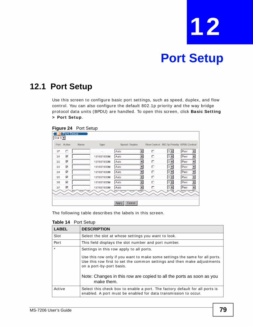
MS-7206 User’s Guide 79
CHAPTER 12 Port Setup
12.1 Port SetupUse this screen to configure basic port settings, such as speed, duplex, and flow control. You can also configure the default 802.1p priority and the way bridge protocol data units (BPDU) are handled. To open this screen, click Basic Setting > Port Setup.
Figure 24 Port Setup
The following table describes the labels in this screen.
Table 14 Port Setup LABEL DESCRIPTIONSlot Select the slot at whose settings you want to look.
Port This field displays the slot number and port number.
* Settings in this row apply to all ports.
Use this row only if you want to make some settings the same for all ports. Use this row first to set the common settings and then make adjustments on a port-by-port basis.
Note: Changes in this row are copied to all the ports as soon as you make them.
Active Select this check box to enable a port. The factory default for all ports is enabled. A port must be enabled for data transmission to occur.
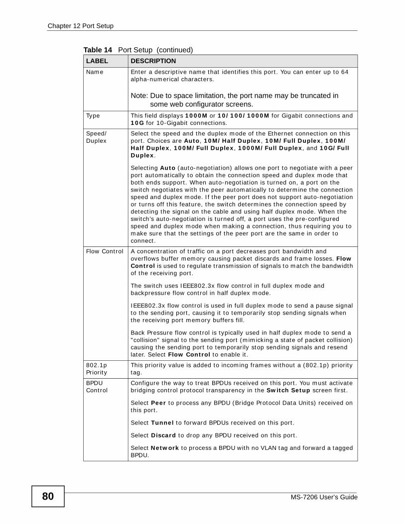
Chapter 12 Port Setup
MS-7206 User’s Guide80
Name Enter a descriptive name that identifies this port. You can enter up to 64 alpha-numerical characters.
Note: Due to space limitation, the port name may be truncated in some web configurator screens.
Type This field displays 1000M or 10/100/1000M for Gigabit connections and 10G for 10-Gigabit connections.
Speed/Duplex
Select the speed and the duplex mode of the Ethernet connection on this port. Choices are Auto, 10M/Half Duplex, 10M/Full Duplex, 100M/Half Duplex, 100M/Full Duplex, 1000M/Full Duplex, and 10G/Full Duplex.
Selecting Auto (auto-negotiation) allows one port to negotiate with a peer port automatically to obtain the connection speed and duplex mode that both ends support. When auto-negotiation is turned on, a port on the switch negotiates with the peer automatically to determine the connection speed and duplex mode. If the peer port does not support auto-negotiation or turns off this feature, the switch determines the connection speed by detecting the signal on the cable and using half duplex mode. When the switch’s auto-negotiation is turned off, a port uses the pre-configured speed and duplex mode when making a connection, thus requiring you to make sure that the settings of the peer port are the same in order to connect.
Flow Control A concentration of traffic on a port decreases port bandwidth and overflows buffer memory causing packet discards and frame losses. Flow Control is used to regulate transmission of signals to match the bandwidth of the receiving port.
The switch uses IEEE802.3x flow control in full duplex mode and backpressure flow control in half duplex mode.
IEEE802.3x flow control is used in full duplex mode to send a pause signal to the sending port, causing it to temporarily stop sending signals when the receiving port memory buffers fill.
Back Pressure flow control is typically used in half duplex mode to send a "collision" signal to the sending port (mimicking a state of packet collision) causing the sending port to temporarily stop sending signals and resend later. Select Flow Control to enable it.
802.1p Priority
This priority value is added to incoming frames without a (802.1p) priority tag.
BPDU Control
Configure the way to treat BPDUs received on this port. You must activate bridging control protocol transparency in the Switch Setup screen first.
Select Peer to process any BPDU (Bridge Protocol Data Units) received on this port.
Select Tunnel to forward BPDUs received on this port.
Select Discard to drop any BPDU received on this port.
Select Network to process a BPDU with no VLAN tag and forward a tagged BPDU.
Table 14 Port Setup (continued)LABEL DESCRIPTION
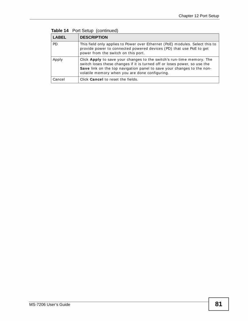
Chapter 12 Port Setup
MS-7206 User’s Guide 81
PD This field only applies to Power over Ethernet (PoE) modules. Select this to provide power to connected powered devices (PD) that use PoE to get power from the switch on this port.
Apply Click Apply to save your changes to the switch’s run-time memory. The switch loses these changes if it is turned off or loses power, so use the Save link on the top navigation panel to save your changes to the non-volatile memory when you are done configuring.
Cancel Click Cancel to reset the fields.
Table 14 Port Setup (continued)LABEL DESCRIPTION

Chapter 12 Port Setup
MS-7206 User’s Guide82
83
PART IVAdvanced
VLAN (85)
Static MAC Forward Setup (101)
Filtering (103)
Spanning Tree Protocol (105)
Bandwidth Control (127)
Broadcast Storm Control (131)
Mirroring (133)
Link Aggregation (135)
Port Authentication (143)
Port Security (149)
Classifier (155)
Policy Rule (161)
Queuing Method (169)
VLAN Stacking (173)
Multicast (179)
AAA (195)
IP Source Guard (207)
Loop Guard (233)

84

MS-7206 User’s Guide 85
CHAPTER 13 VLAN
This chapter introduces VLANs and then describes the screens you use to configure VLAN settings.
13.1 Introduction to VLANsA VLAN (Virtual Local Area Network) allows a physical network to be partitioned into multiple logical networks. Devices on a logical network belong to one group. A device can belong to more than one group. With VLAN, a device cannot directly talk to or hear from devices that are not in the same group(s); the traffic must first go through a router.
In MTU (Multi-Tenant Unit) applications, VLAN is vital in providing isolation and security among the subscribers. When properly configured, VLAN prevents one subscriber from accessing the network resources of another on the same LAN, thus a user will not see the printers and hard disks of another user in the same building.
VLAN also increases network performance by limiting broadcasts to a smaller and more manageable logical broadcast domain. In traditional switched environments, all broadcast packets go to each and every individual port. With VLAN, all broadcasts are confined to a specific broadcast domain.
Note: VLAN is unidirectional; it only governs outgoing traffic.
13.2 Introduction to IEEE 802.1Q Tagged VLANs A tagged VLAN uses an explicit tag (VLAN ID) in the MAC header to identify the VLAN membership of a frame across bridges - they are not confined to the switch on which they were created. The VLANs can be created statically by hand or dynamically through GVRP. The VLAN ID associates a frame with a specific VLAN and provides the information that switches need to process the frame across the network. A tagged frame is four bytes longer than an untagged frame and contains two bytes of TPID (Tag Protocol Identifier, residing within the type/length
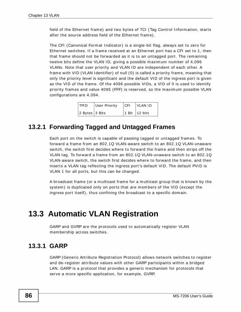
Chapter 13 VLAN
MS-7206 User’s Guide86
field of the Ethernet frame) and two bytes of TCI (Tag Control Information, starts after the source address field of the Ethernet frame).
The CFI (Canonical Format Indicator) is a single-bit flag, always set to zero for Ethernet switches. If a frame received at an Ethernet port has a CFI set to 1, then that frame should not be forwarded as it is to an untagged port. The remaining twelve bits define the VLAN ID, giving a possible maximum number of 4,096 VLANs. Note that user priority and VLAN ID are independent of each other. A frame with VID (VLAN Identifier) of null (0) is called a priority frame, meaning that only the priority level is significant and the default VID of the ingress port is given as the VID of the frame. Of the 4096 possible VIDs, a VID of 0 is used to identify priority frames and value 4095 (FFF) is reserved, so the maximum possible VLAN configurations are 4,094.
13.2.1 Forwarding Tagged and Untagged Frames Each port on the switch is capable of passing tagged or untagged frames. To forward a frame from an 802.1Q VLAN-aware switch to an 802.1Q VLAN-unaware switch, the switch first decides where to forward the frame and then strips off the VLAN tag. To forward a frame from an 802.1Q VLAN-unaware switch to an 802.1Q VLAN-aware switch, the switch first decides where to forward the frame, and then inserts a VLAN tag reflecting the ingress port's default VID. The default PVID is VLAN 1 for all ports, but this can be changed.
A broadcast frame (or a multicast frame for a multicast group that is known by the system) is duplicated only on ports that are members of the VID (except the ingress port itself), thus confining the broadcast to a specific domain.
13.3 Automatic VLAN RegistrationGARP and GVRP are the protocols used to automatically register VLAN membership across switches.
13.3.1 GARP GARP (Generic Attribute Registration Protocol) allows network switches to register and de-register attribute values with other GARP participants within a bridged LAN. GARP is a protocol that provides a generic mechanism for protocols that serve a more specific application, for example, GVRP.
TPID
2 Bytes
User Priority
3 Bits
CFI
1 Bit
VLAN ID
12 bits
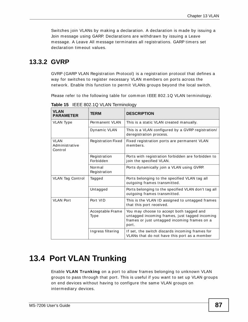
Chapter 13 VLAN
MS-7206 User’s Guide 87
Switches join VLANs by making a declaration. A declaration is made by issuing a Join message using GARP. Declarations are withdrawn by issuing a Leave message. A Leave All message terminates all registrations. GARP timers set declaration timeout values.
13.3.2 GVRPGVRP (GARP VLAN Registration Protocol) is a registration protocol that defines a way for switches to register necessary VLAN members on ports across the network. Enable this function to permit VLANs groups beyond the local switch.
Please refer to the following table for common IEEE 802.1Q VLAN terminology.
13.4 Port VLAN TrunkingEnable VLAN Trunking on a port to allow frames belonging to unknown VLAN groups to pass through that port. This is useful if you want to set up VLAN groups on end devices without having to configure the same VLAN groups on intermediary devices.
Table 15 IEEE 802.1Q VLAN Terminology VLAN PARAMETER TERM DESCRIPTION
VLAN Type Permanent VLAN This is a static VLAN created manually.
Dynamic VLAN This is a VLAN configured by a GVRP registration/deregistration process.
VLAN Administrative Control
Registration Fixed Fixed registration ports are permanent VLAN members.
Registration Forbidden
Ports with registration forbidden are forbidden to join the specified VLAN.
Normal Registration
Ports dynamically join a VLAN using GVRP.
VLAN Tag Control Tagged Ports belonging to the specified VLAN tag all outgoing frames transmitted.
Untagged Ports belonging to the specified VLAN don't tag all outgoing frames transmitted.
VLAN Port Port VID This is the VLAN ID assigned to untagged frames that this port received.
Acceptable Frame Type
You may choose to accept both tagged and untagged incoming frames, just tagged incoming frames or just untagged incoming frames on a port.
Ingress filtering If set, the switch discards incoming frames for VLANs that do not have this port as a member
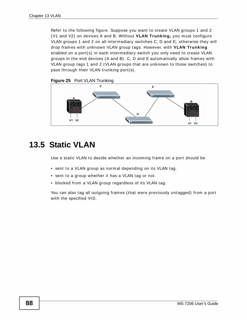
Chapter 13 VLAN
MS-7206 User’s Guide88
Refer to the following figure. Suppose you want to create VLAN groups 1 and 2 (V1 and V2) on devices A and B. Without VLAN Trunking, you must configure VLAN groups 1 and 2 on all intermediary switches C, D and E; otherwise they will drop frames with unknown VLAN group tags. However, with VLAN Trunking enabled on a port(s) in each intermediary switch you only need to create VLAN groups in the end devices (A and B). C, D and E automatically allow frames with VLAN group tags 1 and 2 (VLAN groups that are unknown to those switches) to pass through their VLAN trunking port(s).
Figure 25 Port VLAN Trunking
13.5 Static VLANUse a static VLAN to decide whether an incoming frame on a port should be
• sent to a VLAN group as normal depending on its VLAN tag.
• sent to a group whether it has a VLAN tag or not.
• blocked from a VLAN group regardless of its VLAN tag.
You can also tag all outgoing frames (that were previously untagged) from a port with the specified VID.
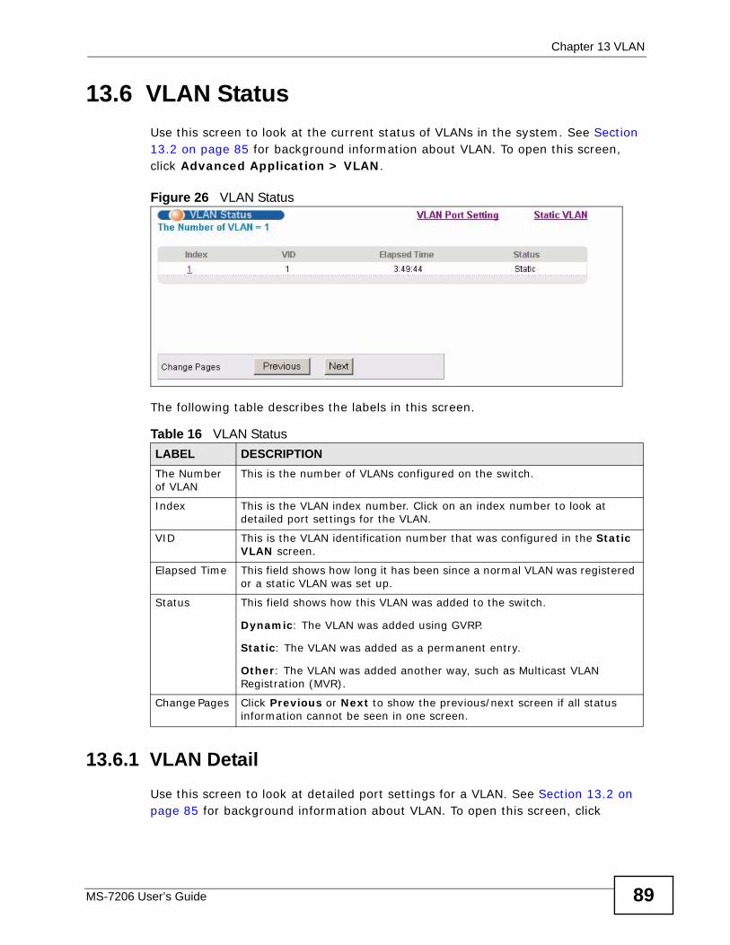
Chapter 13 VLAN
MS-7206 User’s Guide 89
13.6 VLAN Status Use this screen to look at the current status of VLANs in the system. See Section 13.2 on page 85 for background information about VLAN. To open this screen, click Advanced Application > VLAN.
Figure 26 VLAN Status
The following table describes the labels in this screen.
13.6.1 VLAN DetailUse this screen to look at detailed port settings for a VLAN. See Section 13.2 on page 85 for background information about VLAN. To open this screen, click
Table 16 VLAN StatusLABEL DESCRIPTIONThe Number of VLAN
This is the number of VLANs configured on the switch.
Index This is the VLAN index number. Click on an index number to look at detailed port settings for the VLAN.
VID This is the VLAN identification number that was configured in the Static VLAN screen.
Elapsed Time This field shows how long it has been since a normal VLAN was registered or a static VLAN was set up.
Status This field shows how this VLAN was added to the switch.
Dynamic: The VLAN was added using GVRP.
Static: The VLAN was added as a permanent entry.
Other: The VLAN was added another way, such as Multicast VLAN Registration (MVR).
Change Pages Click Previous or Next to show the previous/next screen if all status information cannot be seen in one screen.
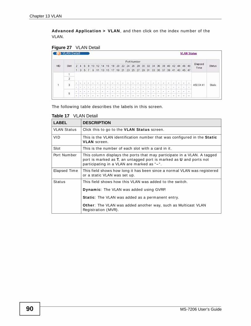
Chapter 13 VLAN
MS-7206 User’s Guide90
Advanced Application > VLAN, and then click on the index number of the VLAN.
Figure 27 VLAN Detail
The following table describes the labels in this screen.
Table 17 VLAN DetailLABEL DESCRIPTIONVLAN Status Click this to go to the VLAN Status screen.
VID This is the VLAN identification number that was configured in the Static VLAN screen.
Slot This is the number of each slot with a card in it.
Port Number This column displays the ports that may participate in a VLAN. A tagged port is marked as T, an untagged port is marked as U and ports not participating in a VLAN are marked as “–“.
Elapsed Time This field shows how long it has been since a normal VLAN was registered or a static VLAN was set up.
Status This field shows how this VLAN was added to the switch.
Dynamic: The VLAN was added using GVRP.
Static: The VLAN was added as a permanent entry.
Other: The VLAN was added another way, such as Multicast VLAN Registration (MVR).
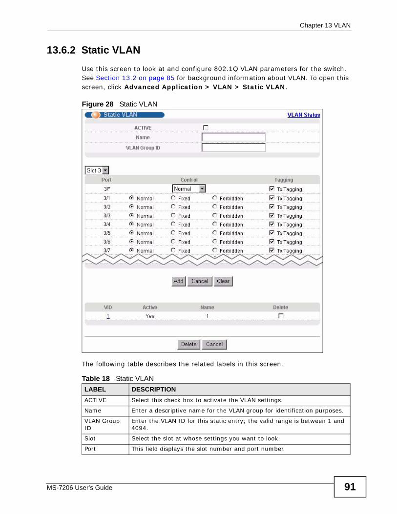
Chapter 13 VLAN
MS-7206 User’s Guide 91
13.6.2 Static VLAN Use this screen to look at and configure 802.1Q VLAN parameters for the switch. See Section 13.2 on page 85 for background information about VLAN. To open this screen, click Advanced Application > VLAN > Static VLAN.
Figure 28 Static VLAN
The following table describes the related labels in this screen.
Table 18 Static VLAN LABEL DESCRIPTIONACTIVE Select this check box to activate the VLAN settings.
Name Enter a descriptive name for the VLAN group for identification purposes.
VLAN Group ID
Enter the VLAN ID for this static entry; the valid range is between 1 and 4094.
Slot Select the slot at whose settings you want to look.
Port This field displays the slot number and port number.
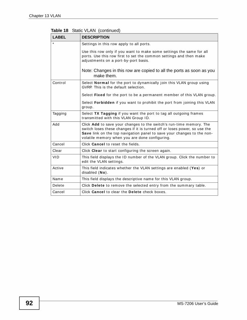
Chapter 13 VLAN
MS-7206 User’s Guide92
* Settings in this row apply to all ports.
Use this row only if you want to make some settings the same for all ports. Use this row first to set the common settings and then make adjustments on a port-by-port basis.
Note: Changes in this row are copied to all the ports as soon as you make them.
Control Select Normal for the port to dynamically join this VLAN group using GVRP. This is the default selection.
Select Fixed for the port to be a permanent member of this VLAN group.
Select Forbidden if you want to prohibit the port from joining this VLAN group.
Tagging Select TX Tagging if you want the port to tag all outgoing frames transmitted with this VLAN Group ID.
Add Click Add to save your changes to the switch’s run-time memory. The switch loses these changes if it is turned off or loses power, so use the Save link on the top navigation panel to save your changes to the non-volatile memory when you are done configuring.
Cancel Click Cancel to reset the fields.
Clear Click Clear to start configuring the screen again.
VID This field displays the ID number of the VLAN group. Click the number to edit the VLAN settings.
Active This field indicates whether the VLAN settings are enabled (Yes) or disabled (No).
Name This field displays the descriptive name for this VLAN group.
Delete Click Delete to remove the selected entry from the summary table.
Cancel Click Cancel to clear the Delete check boxes.
Table 18 Static VLAN (continued)LABEL DESCRIPTION
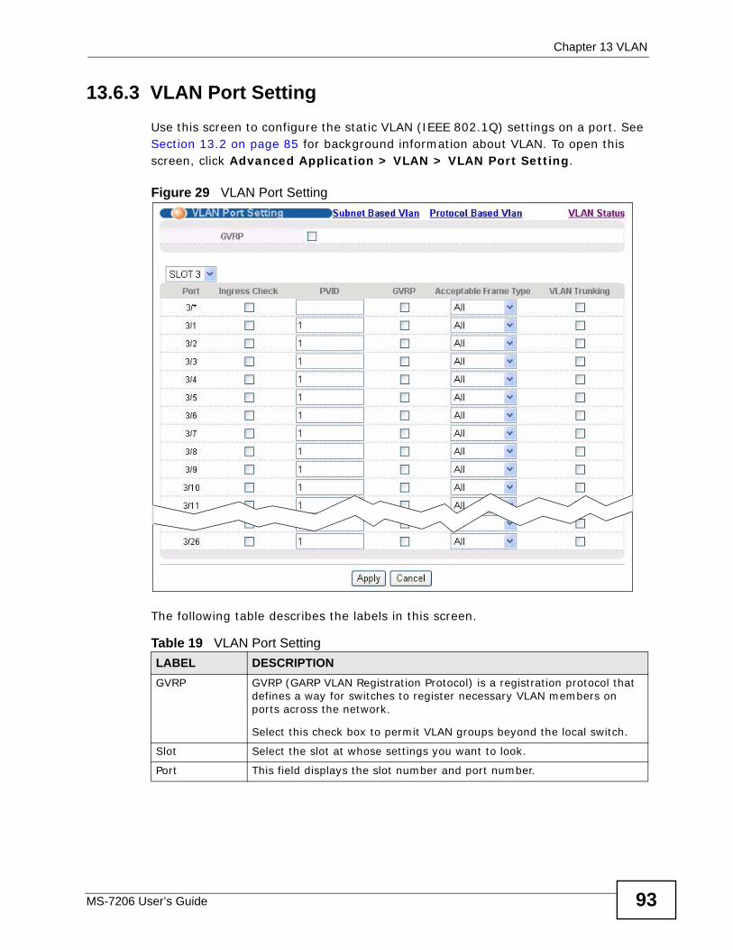
Chapter 13 VLAN
MS-7206 User’s Guide 93
13.6.3 VLAN Port Setting Use this screen to configure the static VLAN (IEEE 802.1Q) settings on a port. See Section 13.2 on page 85 for background information about VLAN. To open this screen, click Advanced Application > VLAN > VLAN Port Setting.
Figure 29 VLAN Port Setting
The following table describes the labels in this screen.
Table 19 VLAN Port Setting LABEL DESCRIPTIONGVRP GVRP (GARP VLAN Registration Protocol) is a registration protocol that
defines a way for switches to register necessary VLAN members on ports across the network.
Select this check box to permit VLAN groups beyond the local switch.
Slot Select the slot at whose settings you want to look.
Port This field displays the slot number and port number.
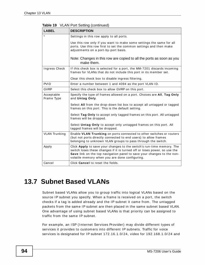
Chapter 13 VLAN
MS-7206 User’s Guide94
13.7 Subnet Based VLANs Subnet based VLANs allow you to group traffic into logical VLANs based on the source IP subnet you specify. When a frame is received on a port, the switch checks if a tag is added already and the IP subnet it came from. The untagged packets from the same IP subnet are then placed in the same subnet based VLAN. One advantage of using subnet based VLANs is that priority can be assigned to traffic from the same IP subnet.
For example, an ISP (Internet Services Provider) may divide different types of services it provides to customers into different IP subnets. Traffic for voice services is designated for IP subnet 172.16.1.0/24, video for 192.168.1.0/24 and
* Settings in this row apply to all ports.
Use this row only if you want to make some settings the same for all ports. Use this row first to set the common settings and then make adjustments on a port-by-port basis.
Note: Changes in this row are copied to all the ports as soon as you make them.
Ingress Check If this check box is selected for a port, the MM-7201 discards incoming frames for VLANs that do not include this port in its member set.
Clear this check box to disable ingress filtering.
PVID Enter a number between 1 and 4094 as the port VLAN ID.
GVRP Select this check box to allow GVRP on this port.
Acceptable Frame Type
Specify the type of frames allowed on a port. Choices are All, Tag Only and Untag Only.
Select All from the drop-down list box to accept all untagged or tagged frames on this port. This is the default setting.
Select Tag Only to accept only tagged frames on this port. All untagged frames will be dropped.
Select Untag Only to accept only untagged frames on this port. All tagged frames will be dropped.
VLAN Trunking Enable VLAN Trunking on ports connected to other switches or routers (but not ports directly connected to end users) to allow frames belonging to unknown VLAN groups to pass through the switch.
Apply Click Apply to save your changes to the switch’s run-time memory. The switch loses these changes if it is turned off or loses power, so use the Save link on the top navigation panel to save your changes to the non-volatile memory when you are done configuring.
Cancel Click Cancel to reset the fields.
Table 19 VLAN Port Setting (continued) LABEL DESCRIPTION
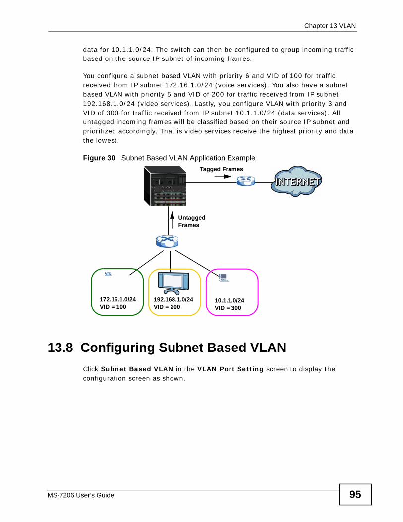
Chapter 13 VLAN
MS-7206 User’s Guide 95
data for 10.1.1.0/24. The switch can then be configured to group incoming traffic based on the source IP subnet of incoming frames.
You configure a subnet based VLAN with priority 6 and VID of 100 for traffic received from IP subnet 172.16.1.0/24 (voice services). You also have a subnet based VLAN with priority 5 and VID of 200 for traffic received from IP subnet 192.168.1.0/24 (video services). Lastly, you configure VLAN with priority 3 and VID of 300 for traffic received from IP subnet 10.1.1.0/24 (data services). All untagged incoming frames will be classified based on their source IP subnet and prioritized accordingly. That is video services receive the highest priority and data the lowest.
Figure 30 Subnet Based VLAN Application Example
13.8 Configuring Subnet Based VLAN Click Subnet Based VLAN in the VLAN Port Setting screen to display the configuration screen as shown.
192.168.1.0/24172.16.1.0/24VID = 100 VID = 200
UntaggedFrames
Tagged Frames
10.1.1.0/24VID = 300
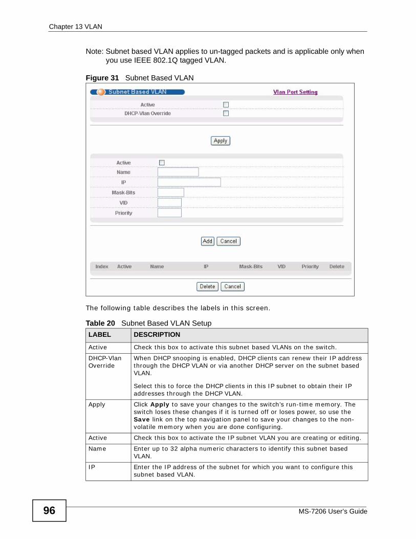
Chapter 13 VLAN
MS-7206 User’s Guide96
Note: Subnet based VLAN applies to un-tagged packets and is applicable only when you use IEEE 802.1Q tagged VLAN.
Figure 31 Subnet Based VLAN
The following table describes the labels in this screen.
Table 20 Subnet Based VLAN Setup LABEL DESCRIPTION
Active Check this box to activate this subnet based VLANs on the switch.
DHCP-Vlan Override
When DHCP snooping is enabled, DHCP clients can renew their IP address through the DHCP VLAN or via another DHCP server on the subnet based VLAN.
Select this to force the DHCP clients in this IP subnet to obtain their IP addresses through the DHCP VLAN.
Apply Click Apply to save your changes to the switch’s run-time memory. The switch loses these changes if it is turned off or loses power, so use the Save link on the top navigation panel to save your changes to the non-volatile memory when you are done configuring.
Active Check this box to activate the IP subnet VLAN you are creating or editing.
Name Enter up to 32 alpha numeric characters to identify this subnet based VLAN.
IP Enter the IP address of the subnet for which you want to configure this subnet based VLAN.
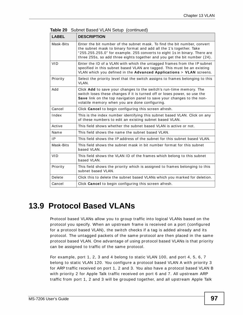
Chapter 13 VLAN
MS-7206 User’s Guide 97
13.9 Protocol Based VLANs Protocol based VLANs allow you to group traffic into logical VLANs based on the protocol you specify. When an upstream frame is received on a port (configured for a protocol based VLAN), the switch checks if a tag is added already and its protocol. The untagged packets of the same protocol are then placed in the same protocol based VLAN. One advantage of using protocol based VLANs is that priority can be assigned to traffic of the same protocol.
For example, port 1, 2, 3 and 4 belong to static VLAN 100, and port 4, 5, 6, 7 belong to static VLAN 120. You configure a protocol based VLAN A with priority 3 for ARP traffic received on port 1, 2 and 3. You also have a protocol based VLAN B with priority 2 for Apple Talk traffic received on port 6 and 7. All upstream ARP traffic from port 1, 2 and 3 will be grouped together, and all upstream Apple Talk
Mask-Bits Enter the bit number of the subnet mask. To find the bit number, convert the subnet mask to binary format and add all the 1’s together. Take “255.255.255.0” for example. 255 converts to eight 1s in binary. There are three 255s, so add three eights together and you get the bit number (24).
VID Enter the ID of a VLAN with which the untagged frames from the IP subnet specified in this subnet based VLAN are tagged. This must be an existing VLAN which you defined in the Advanced Applications > VLAN screens.
Priority Select the priority level that the switch assigns to frames belonging to this VLAN.
Add Click Add to save your changes to the switch’s run-time memory. The switch loses these changes if it is turned off or loses power, so use the Save link on the top navigation panel to save your changes to the non-volatile memory when you are done configuring.
Cancel Click Cancel to begin configuring this screen afresh.
Index This is the index number identifying this subnet based VLAN. Click on any of these numbers to edit an existing subnet based VLAN.
Active This field shows whether the subnet based VLAN is active or not.
Name This field shows the name the subnet based VLAN.
IP This field shows the IP address of the subnet for this subnet based VLAN.
Mask-Bits This field shows the subnet mask in bit number format for this subnet based VLAN.
VID This field shows the VLAN ID of the frames which belong to this subnet based VLAN.
Priority This field shows the priority which is assigned to frames belonging to this subnet based VLAN.
Delete Click this to delete the subnet based VLANs which you marked for deletion.
Cancel Click Cancel to begin configuring this screen afresh.
Table 20 Subnet Based VLAN Setup (continued)LABEL DESCRIPTION
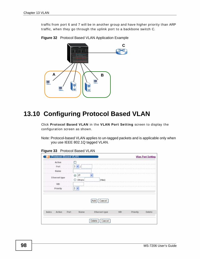
Chapter 13 VLAN
MS-7206 User’s Guide98
traffic from port 6 and 7 will be in another group and have higher priority than ARP traffic, when they go through the uplink port to a backbone switch C.
Figure 32 Protocol Based VLAN Application Example
13.10 Configuring Protocol Based VLAN Click Protocol Based VLAN in the VLAN Port Setting screen to display the configuration screen as shown.
Note: Protocol-based VLAN applies to un-tagged packets and is applicable only when you use IEEE 802.1Q tagged VLAN.
Figure 33 Protocol Based VLAN
A B
C
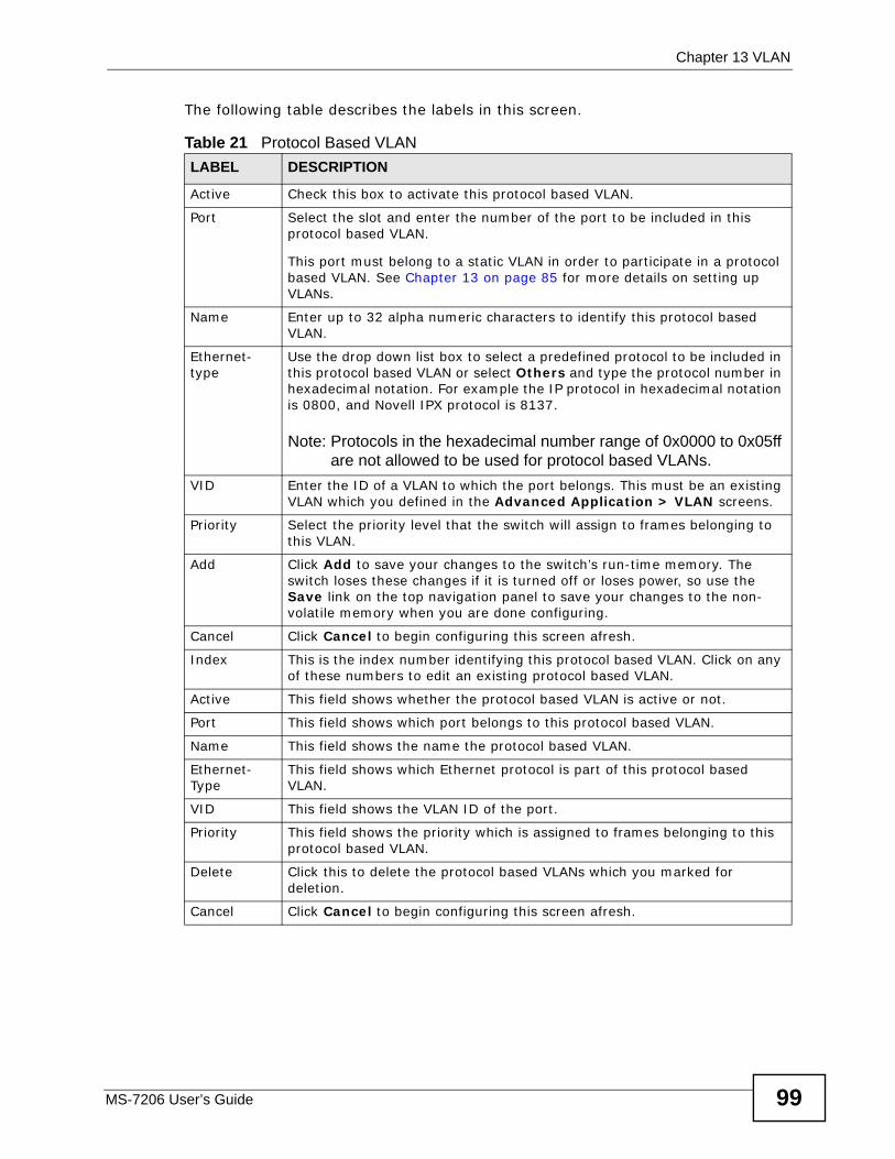
Chapter 13 VLAN
MS-7206 User’s Guide 99
The following table describes the labels in this screen.
Table 21 Protocol Based VLAN LABEL DESCRIPTION
Active Check this box to activate this protocol based VLAN.
Port Select the slot and enter the number of the port to be included in this protocol based VLAN.
This port must belong to a static VLAN in order to participate in a protocol based VLAN. See Chapter 13 on page 85 for more details on setting up VLANs.
Name Enter up to 32 alpha numeric characters to identify this protocol based VLAN.
Ethernet-type
Use the drop down list box to select a predefined protocol to be included in this protocol based VLAN or select Others and type the protocol number in hexadecimal notation. For example the IP protocol in hexadecimal notation is 0800, and Novell IPX protocol is 8137.
Note: Protocols in the hexadecimal number range of 0x0000 to 0x05ff are not allowed to be used for protocol based VLANs.
VID Enter the ID of a VLAN to which the port belongs. This must be an existing VLAN which you defined in the Advanced Application > VLAN screens.
Priority Select the priority level that the switch will assign to frames belonging to this VLAN.
Add Click Add to save your changes to the switch’s run-time memory. The switch loses these changes if it is turned off or loses power, so use the Save link on the top navigation panel to save your changes to the non-volatile memory when you are done configuring.
Cancel Click Cancel to begin configuring this screen afresh.
Index This is the index number identifying this protocol based VLAN. Click on any of these numbers to edit an existing protocol based VLAN.
Active This field shows whether the protocol based VLAN is active or not.
Port This field shows which port belongs to this protocol based VLAN.
Name This field shows the name the protocol based VLAN.
Ethernet-Type
This field shows which Ethernet protocol is part of this protocol based VLAN.
VID This field shows the VLAN ID of the port.
Priority This field shows the priority which is assigned to frames belonging to this protocol based VLAN.
Delete Click this to delete the protocol based VLANs which you marked for deletion.
Cancel Click Cancel to begin configuring this screen afresh.
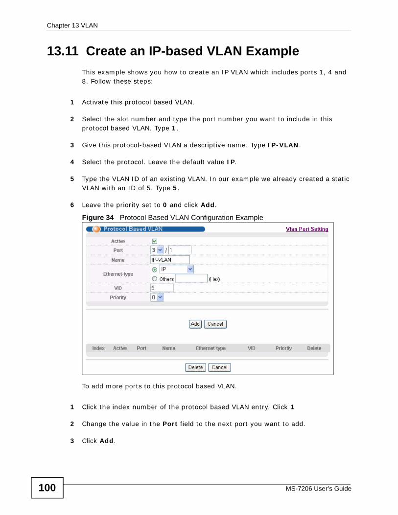
Chapter 13 VLAN
MS-7206 User’s Guide100
13.11 Create an IP-based VLAN ExampleThis example shows you how to create an IP VLAN which includes ports 1, 4 and 8. Follow these steps:
1 Activate this protocol based VLAN.
2 Select the slot number and type the port number you want to include in this protocol based VLAN. Type 1.
3 Give this protocol-based VLAN a descriptive name. Type IP-VLAN.
4 Select the protocol. Leave the default value IP.
5 Type the VLAN ID of an existing VLAN. In our example we already created a static VLAN with an ID of 5. Type 5.
6 Leave the priority set to 0 and click Add.
Figure 34 Protocol Based VLAN Configuration Example
To add more ports to this protocol based VLAN.
1 Click the index number of the protocol based VLAN entry. Click 1
2 Change the value in the Port field to the next port you want to add.
3 Click Add.
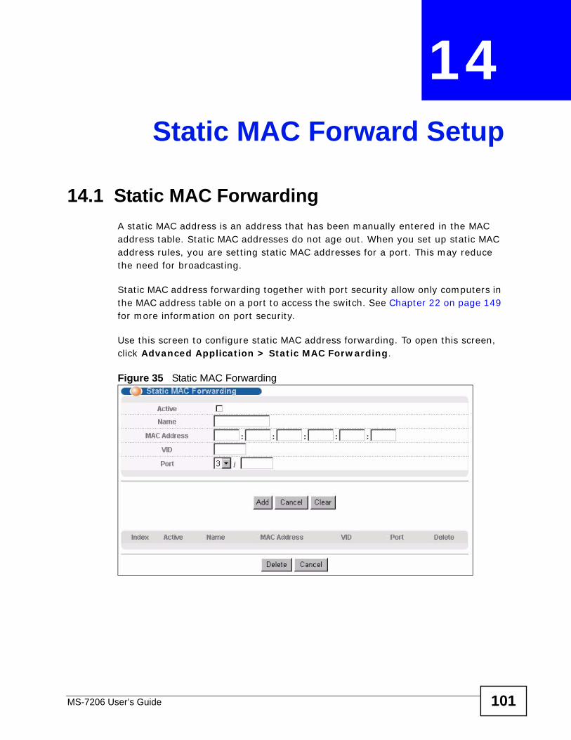
MS-7206 User’s Guide 101
CHAPTER 14 Static MAC Forward Setup
14.1 Static MAC Forwarding A static MAC address is an address that has been manually entered in the MAC address table. Static MAC addresses do not age out. When you set up static MAC address rules, you are setting static MAC addresses for a port. This may reduce the need for broadcasting.
Static MAC address forwarding together with port security allow only computers in the MAC address table on a port to access the switch. See Chapter 22 on page 149 for more information on port security.
Use this screen to configure static MAC address forwarding. To open this screen, click Advanced Application > Static MAC Forwarding.
Figure 35 Static MAC Forwarding
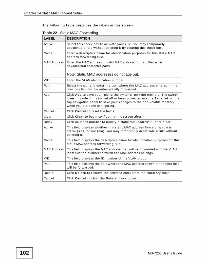
Chapter 14 Static MAC Forward Setup
MS-7206 User’s Guide102
The following table describes the labels in this screen.
Table 22 Static MAC Forwarding LABEL DESCRIPTIONActive Select this check box to activate your rule. You may temporarily
deactivate a rule without deleting it by clearing this check box.
Name Enter a descriptive name for identification purposes for this static MAC address forwarding rule.
MAC Address Enter the MAC address in valid MAC address format, that is, six hexadecimal character pairs.
Note: Static MAC addresses do not age out.VID Enter the VLAN identification number.
Port Select the slot and enter the port where the MAC address entered in the previous field will be automatically forwarded.
Add Click Add to save your rule to the switch’s run-time memory. The switch loses this rule if it is turned off or loses power, so use the Save link on the top navigation panel to save your changes to the non-volatile memory when you are done configuring.
Cancel Click Cancel to reset the fields.
Clear Click Clear to begin configuring this screen afresh.
Index Click an index number to modify a static MAC address rule for a port.
Active This field displays whether this static MAC address forwarding rule is active (Yes) or not (No). You may temporarily deactivate a rule without deleting it.
Name This field displays the descriptive name for identification purposes for this static MAC address-forwarding rule.
MAC Address This field displays the MAC address that will be forwarded and the VLAN identification number to which the MAC address belongs.
VID This field displays the ID number of the VLAN group.
Port This field displays the port where the MAC address shown in the next field will be forwarded.
Delete Click Delete to remove the selected entry from the summary table.
Cancel Click Cancel to clear the Delete check boxes.
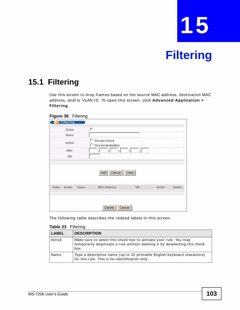
MS-7206 User’s Guide 103
CHAPTER 15 Filtering
15.1 Filtering Use this screen to drop frames based on the source MAC address, destination MAC address, and/or VLAN ID. To open this screen, click Advanced Application > Filtering.
Figure 36 Filtering
The following table describes the related labels in this screen.
Table 23 Filtering LABEL DESCRIPTIONActive Make sure to select this check box to activate your rule. You may
temporarily deactivate a rule without deleting it by deselecting this check box.
Name Type a descriptive name (up to 32 printable English keyboard characters) for this rule. This is for identification only.
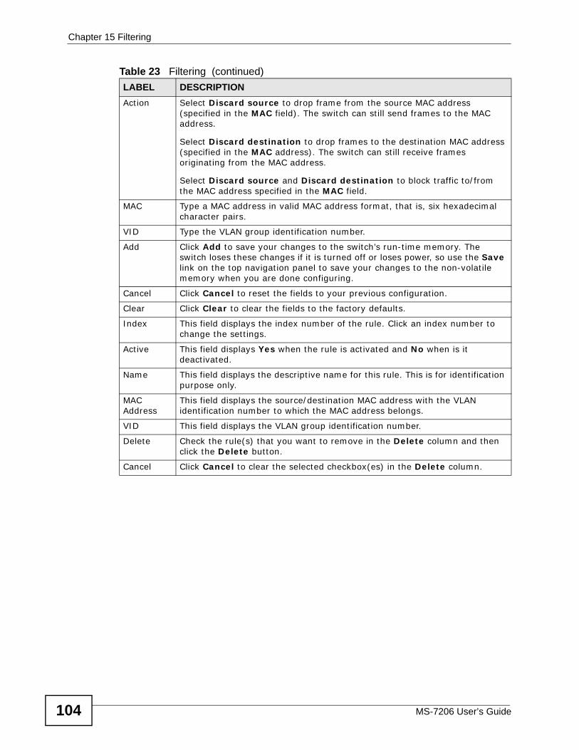
Chapter 15 Filtering
MS-7206 User’s Guide104
Action Select Discard source to drop frame from the source MAC address (specified in the MAC field). The switch can still send frames to the MAC address.
Select Discard destination to drop frames to the destination MAC address (specified in the MAC address). The switch can still receive frames originating from the MAC address.
Select Discard source and Discard destination to block traffic to/from the MAC address specified in the MAC field.
MAC Type a MAC address in valid MAC address format, that is, six hexadecimal character pairs.
VID Type the VLAN group identification number.
Add Click Add to save your changes to the switch’s run-time memory. The switch loses these changes if it is turned off or loses power, so use the Save link on the top navigation panel to save your changes to the non-volatile memory when you are done configuring.
Cancel Click Cancel to reset the fields to your previous configuration.
Clear Click Clear to clear the fields to the factory defaults.
Index This field displays the index number of the rule. Click an index number to change the settings.
Active This field displays Yes when the rule is activated and No when is it deactivated.
Name This field displays the descriptive name for this rule. This is for identification purpose only.
MAC Address
This field displays the source/destination MAC address with the VLAN identification number to which the MAC address belongs.
VID This field displays the VLAN group identification number.
Delete Check the rule(s) that you want to remove in the Delete column and then click the Delete button.
Cancel Click Cancel to clear the selected checkbox(es) in the Delete column.
Table 23 Filtering (continued)LABEL DESCRIPTION
MS-7206 User’s Guide 105
CHAPTER 16 Spanning Tree Protocol
The switch supports Spanning Tree Protocol (STP) and Rapid Spanning Tree Protocol (RSTP) as defined in the following standards.
• IEEE 802.1D Spanning Tree Protocol
• IEEE 802.1w Rapid Spanning Tree Protocol
• IEEE 802.1s Multiple Spanning Tree Protocol
The switch also allows you to set up multiple STP configurations (or trees). Ports can then be assigned to the trees.
16.1 STP/RSTP Overview (R)STP detects and breaks network loops and provides backup links between switches, bridges or routers. It allows a switch to interact with other (R)STP -compliant switches in your network to ensure that only one path exists between any two stations on the network.
The switch uses IEEE 802.1w RSTP (Rapid Spanning Tree Protocol) that allows faster convergence of the spanning tree than STP (while also being backwards compatible with STP-only aware bridges). In RSTP, topology change information is directly propagated throughout the network from the device that generates the topology change. In STP, a longer delay is required as the device that causes a topology change first notifies the root bridge that then notifies the network. Both RSTP and STP flush unwanted learned addresses from the filtering database. In RSTP, the port states are Discarding, Learning, and Forwarding.
Note: In this user’s guide, “STP” refers to both STP and RSTP.
16.1.1 STP Terminology The root bridge is the base of the spanning tree.
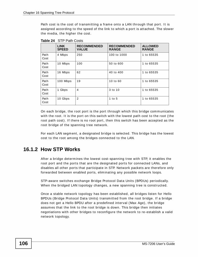
Chapter 16 Spanning Tree Protocol
MS-7206 User’s Guide106
Path cost is the cost of transmitting a frame onto a LAN through that port. It is assigned according to the speed of the link to which a port is attached. The slower the media, the higher the cost.
On each bridge, the root port is the port through which this bridge communicates with the root. It is the port on this switch with the lowest path cost to the root (the root path cost). If there is no root port, then this switch has been accepted as the root bridge of the spanning tree network.
For each LAN segment, a designated bridge is selected. This bridge has the lowest cost to the root among the bridges connected to the LAN.
16.1.2 How STP Works After a bridge determines the lowest cost-spanning tree with STP, it enables the root port and the ports that are the designated ports for connected LANs, and disables all other ports that participate in STP. Network packets are therefore only forwarded between enabled ports, eliminating any possible network loops.
STP-aware switches exchange Bridge Protocol Data Units (BPDUs) periodically. When the bridged LAN topology changes, a new spanning tree is constructed.
Once a stable network topology has been established, all bridges listen for Hello BPDUs (Bridge Protocol Data Units) transmitted from the root bridge. If a bridge does not get a Hello BPDU after a predefined interval (Max Age), the bridge assumes that the link to the root bridge is down. This bridge then initiates negotiations with other bridges to reconfigure the network to re-establish a valid network topology.
Table 24 STP Path CostsLINK SPEED
RECOMMENDED VALUE
RECOMMENDED RANGE
ALLOWED RANGE
Path Cost
4 Mbps 250 100 to 1000 1 to 65535
Path Cost
10 Mbps 100 50 to 600 1 to 65535
Path Cost
16 Mbps 62 40 to 400 1 to 65535
Path Cost
100 Mbps 19 10 to 60 1 to 65535
Path Cost
1 Gbps 4 3 to 10 1 to 65535
Path Cost
10 Gbps 2 1 to 5 1 to 65535
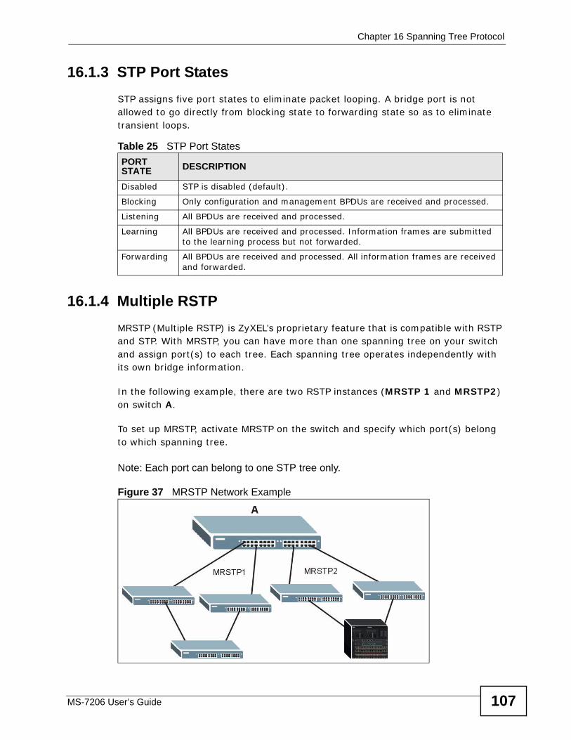
Chapter 16 Spanning Tree Protocol
MS-7206 User’s Guide 107
16.1.3 STP Port States STP assigns five port states to eliminate packet looping. A bridge port is not allowed to go directly from blocking state to forwarding state so as to eliminate transient loops.
16.1.4 Multiple RSTP MRSTP (Multiple RSTP) is ZyXEL’s proprietary feature that is compatible with RSTP and STP. With MRSTP, you can have more than one spanning tree on your switch and assign port(s) to each tree. Each spanning tree operates independently with its own bridge information.
In the following example, there are two RSTP instances (MRSTP 1 and MRSTP2) on switch A.
To set up MRSTP, activate MRSTP on the switch and specify which port(s) belong to which spanning tree.
Note: Each port can belong to one STP tree only.
Figure 37 MRSTP Network Example
Table 25 STP Port StatesPORT STATE DESCRIPTION
Disabled STP is disabled (default).
Blocking Only configuration and management BPDUs are received and processed.
Listening All BPDUs are received and processed.
Learning All BPDUs are received and processed. Information frames are submitted to the learning process but not forwarded.
Forwarding All BPDUs are received and processed. All information frames are received and forwarded.
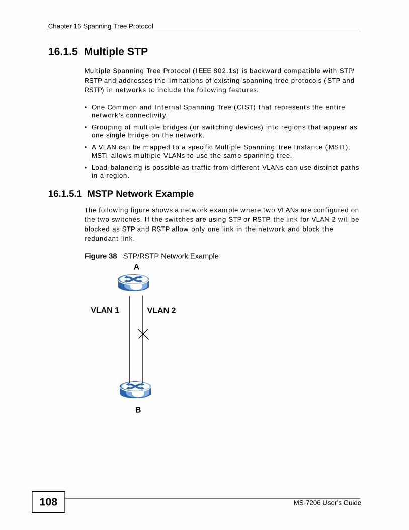
Chapter 16 Spanning Tree Protocol
MS-7206 User’s Guide108
16.1.5 Multiple STP Multiple Spanning Tree Protocol (IEEE 802.1s) is backward compatible with STP/RSTP and addresses the limitations of existing spanning tree protocols (STP and RSTP) in networks to include the following features:
• One Common and Internal Spanning Tree (CIST) that represents the entire network’s connectivity.
• Grouping of multiple bridges (or switching devices) into regions that appear as one single bridge on the network.
• A VLAN can be mapped to a specific Multiple Spanning Tree Instance (MSTI). MSTI allows multiple VLANs to use the same spanning tree.
• Load-balancing is possible as traffic from different VLANs can use distinct paths in a region.
16.1.5.1 MSTP Network ExampleThe following figure shows a network example where two VLANs are configured on the two switches. If the switches are using STP or RSTP, the link for VLAN 2 will be blocked as STP and RSTP allow only one link in the network and block the redundant link.
Figure 38 STP/RSTP Network Example A
B
VLAN 1 VLAN 2
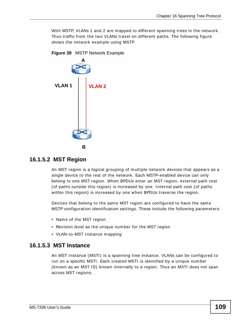
Chapter 16 Spanning Tree Protocol
MS-7206 User’s Guide 109
With MSTP, VLANs 1 and 2 are mapped to different spanning trees in the network. Thus traffic from the two VLANs travel on different paths. The following figure shows the network example using MSTP.
Figure 39 MSTP Network Example
16.1.5.2 MST Region An MST region is a logical grouping of multiple network devices that appears as a single device to the rest of the network. Each MSTP-enabled device can only belong to one MST region. When BPDUs enter an MST region, external path cost (of paths outside this region) is increased by one. Internal path cost (of paths within this region) is increased by one when BPDUs traverse the region.
Devices that belong to the same MST region are configured to have the same MSTP configuration identification settings. These include the following parameters:
• Name of the MST region
• Revision level as the unique number for the MST region
• VLAN-to-MST Instance mapping
16.1.5.3 MST Instance An MST Instance (MSTI) is a spanning tree instance. VLANs can be configured to run on a specific MSTI. Each created MSTI is identified by a unique number (known as an MST ID) known internally to a region. Thus an MSTI does not span across MST regions.
A
B
VLAN 1 VLAN 2
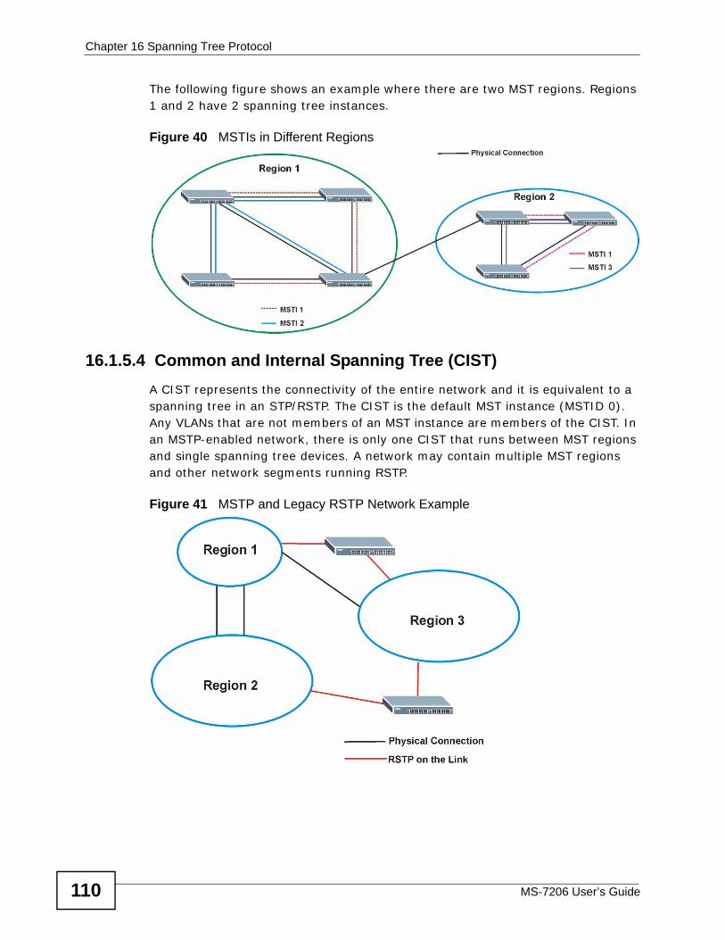
Chapter 16 Spanning Tree Protocol
MS-7206 User’s Guide110
The following figure shows an example where there are two MST regions. Regions 1 and 2 have 2 spanning tree instances.
Figure 40 MSTIs in Different Regions
16.1.5.4 Common and Internal Spanning Tree (CIST) A CIST represents the connectivity of the entire network and it is equivalent to a spanning tree in an STP/RSTP. The CIST is the default MST instance (MSTID 0). Any VLANs that are not members of an MST instance are members of the CIST. In an MSTP-enabled network, there is only one CIST that runs between MST regions and single spanning tree devices. A network may contain multiple MST regions and other network segments running RSTP.
Figure 41 MSTP and Legacy RSTP Network Example
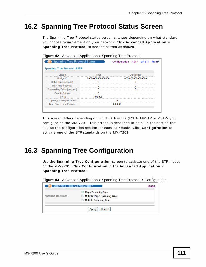
Chapter 16 Spanning Tree Protocol
MS-7206 User’s Guide 111
16.2 Spanning Tree Protocol Status Screen The Spanning Tree Protocol status screen changes depending on what standard you choose to implement on your network. Click Advanced Application > Spanning Tree Protocol to see the screen as shown.
Figure 42 Advanced Application > Spanning Tree Protocol
This screen differs depending on which STP mode (RSTP, MRSTP or MSTP) you configure on the MM-7201. This screen is described in detail in the section that follows the configuration section for each STP mode. Click Configuration to activate one of the STP standards on the MM-7201.
16.3 Spanning Tree Configuration Use the Spanning Tree Configuration screen to activate one of the STP modes on the MM-7201. Click Configuration in the Advanced Application > Spanning Tree Protocol.
Figure 43 Advanced Application > Spanning Tree Protocol > Configuration
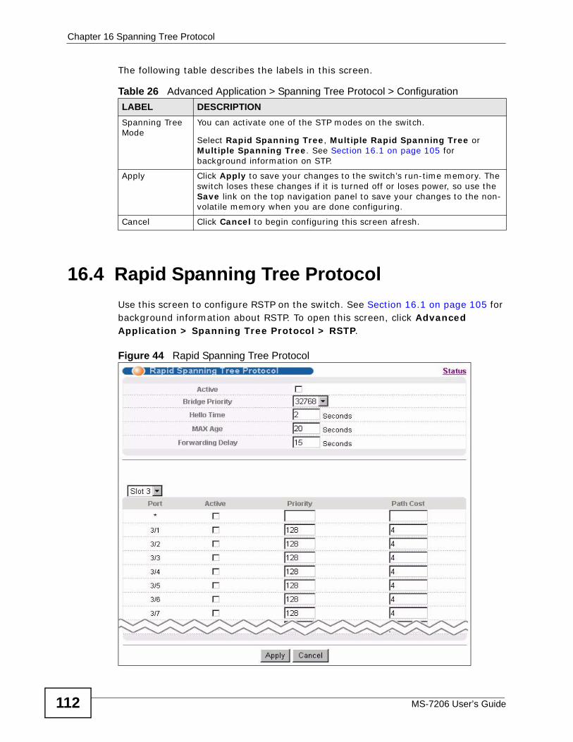
Chapter 16 Spanning Tree Protocol
MS-7206 User’s Guide112
The following table describes the labels in this screen.
16.4 Rapid Spanning Tree Protocol Use this screen to configure RSTP on the switch. See Section 16.1 on page 105 for background information about RSTP. To open this screen, click Advanced Application > Spanning Tree Protocol > RSTP.
Figure 44 Rapid Spanning Tree Protocol
Table 26 Advanced Application > Spanning Tree Protocol > Configuration LABEL DESCRIPTIONSpanning Tree Mode
You can activate one of the STP modes on the switch.
Select Rapid Spanning Tree, Multiple Rapid Spanning Tree or Multiple Spanning Tree. See Section 16.1 on page 105 for background information on STP.
Apply Click Apply to save your changes to the switch’s run-time memory. The switch loses these changes if it is turned off or loses power, so use the Save link on the top navigation panel to save your changes to the non-volatile memory when you are done configuring.
Cancel Click Cancel to begin configuring this screen afresh.
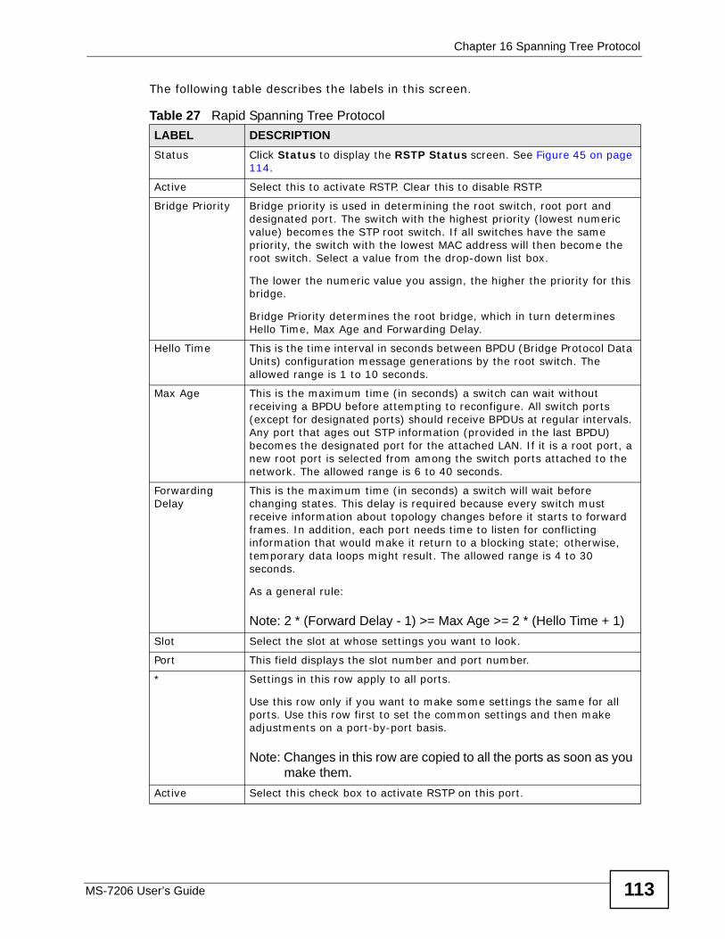
Chapter 16 Spanning Tree Protocol
MS-7206 User’s Guide 113
The following table describes the labels in this screen.
Table 27 Rapid Spanning Tree ProtocolLABEL DESCRIPTIONStatus Click Status to display the RSTP Status screen. See Figure 45 on page
114.
Active Select this to activate RSTP. Clear this to disable RSTP.
Bridge Priority Bridge priority is used in determining the root switch, root port and designated port. The switch with the highest priority (lowest numeric value) becomes the STP root switch. If all switches have the same priority, the switch with the lowest MAC address will then become the root switch. Select a value from the drop-down list box.
The lower the numeric value you assign, the higher the priority for this bridge.
Bridge Priority determines the root bridge, which in turn determines Hello Time, Max Age and Forwarding Delay.
Hello Time This is the time interval in seconds between BPDU (Bridge Protocol Data Units) configuration message generations by the root switch. The allowed range is 1 to 10 seconds.
Max Age This is the maximum time (in seconds) a switch can wait without receiving a BPDU before attempting to reconfigure. All switch ports (except for designated ports) should receive BPDUs at regular intervals. Any port that ages out STP information (provided in the last BPDU) becomes the designated port for the attached LAN. If it is a root port, a new root port is selected from among the switch ports attached to the network. The allowed range is 6 to 40 seconds.
Forwarding Delay
This is the maximum time (in seconds) a switch will wait before changing states. This delay is required because every switch must receive information about topology changes before it starts to forward frames. In addition, each port needs time to listen for conflicting information that would make it return to a blocking state; otherwise, temporary data loops might result. The allowed range is 4 to 30 seconds.
As a general rule:
Note: 2 * (Forward Delay - 1) >= Max Age >= 2 * (Hello Time + 1)Slot Select the slot at whose settings you want to look.
Port This field displays the slot number and port number.
* Settings in this row apply to all ports.
Use this row only if you want to make some settings the same for all ports. Use this row first to set the common settings and then make adjustments on a port-by-port basis.
Note: Changes in this row are copied to all the ports as soon as you make them.
Active Select this check box to activate RSTP on this port.
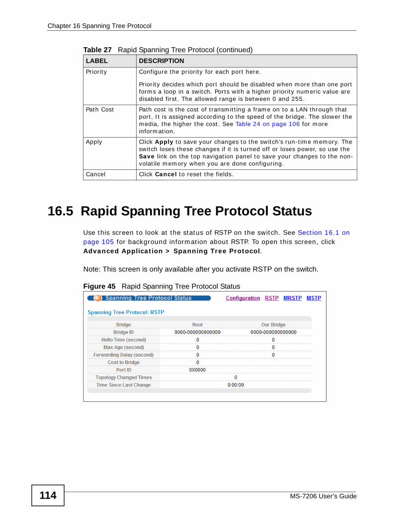
Chapter 16 Spanning Tree Protocol
MS-7206 User’s Guide114
16.5 Rapid Spanning Tree Protocol Status Use this screen to look at the status of RSTP on the switch. See Section 16.1 on page 105 for background information about RSTP. To open this screen, click Advanced Application > Spanning Tree Protocol.
Note: This screen is only available after you activate RSTP on the switch.
Figure 45 Rapid Spanning Tree Protocol Status
Priority Configure the priority for each port here.
Priority decides which port should be disabled when more than one port forms a loop in a switch. Ports with a higher priority numeric value are disabled first. The allowed range is between 0 and 255.
Path Cost Path cost is the cost of transmitting a frame on to a LAN through that port. It is assigned according to the speed of the bridge. The slower the media, the higher the cost. See Table 24 on page 106 for more information.
Apply Click Apply to save your changes to the switch’s run-time memory. The switch loses these changes if it is turned off or loses power, so use the Save link on the top navigation panel to save your changes to the non-volatile memory when you are done configuring.
Cancel Click Cancel to reset the fields.
Table 27 Rapid Spanning Tree Protocol (continued)LABEL DESCRIPTION
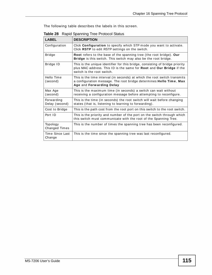
Chapter 16 Spanning Tree Protocol
MS-7206 User’s Guide 115
The following table describes the labels in this screen.
Table 28 Rapid Spanning Tree Protocol Status LABEL DESCRIPTIONConfiguration Click Configuration to specify which STP mode you want to activate.
Click RSTP to edit RSTP settings on the switch.
Bridge Root refers to the base of the spanning tree (the root bridge). Our Bridge is this switch. This switch may also be the root bridge.
Bridge ID This is the unique identifier for this bridge, consisting of bridge priority plus MAC address. This ID is the same for Root and Our Bridge if the switch is the root switch.
Hello Time (second)
This is the time interval (in seconds) at which the root switch transmits a configuration message. The root bridge determines Hello Time, Max Age and Forwarding Delay
Max Age (second)
This is the maximum time (in seconds) a switch can wait without receiving a configuration message before attempting to reconfigure.
Forwarding Delay (second)
This is the time (in seconds) the root switch will wait before changing states (that is, listening to learning to forwarding).
Cost to Bridge This is the path cost from the root port on this switch to the root switch.
Port ID This is the priority and number of the port on the switch through which this switch must communicate with the root of the Spanning Tree.
Topology Changed Times
This is the number of times the spanning tree has been reconfigured.
Time Since Last Change
This is the time since the spanning tree was last reconfigured.
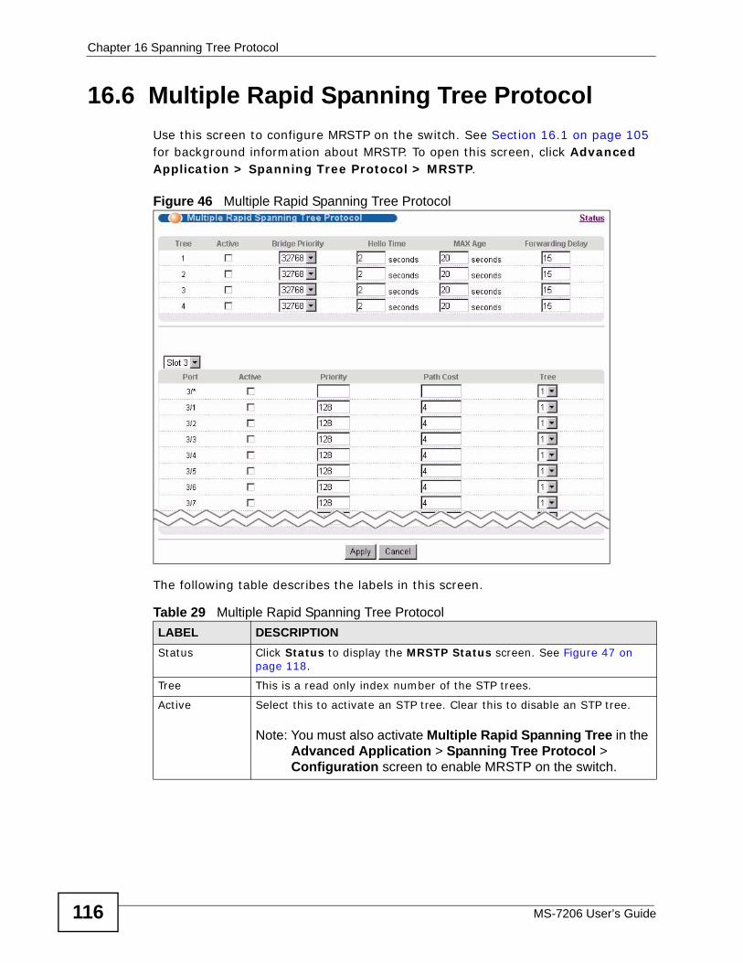
Chapter 16 Spanning Tree Protocol
MS-7206 User’s Guide116
16.6 Multiple Rapid Spanning Tree Protocol Use this screen to configure MRSTP on the switch. See Section 16.1 on page 105 for background information about MRSTP. To open this screen, click Advanced Application > Spanning Tree Protocol > MRSTP.
Figure 46 Multiple Rapid Spanning Tree Protocol
The following table describes the labels in this screen.
Table 29 Multiple Rapid Spanning Tree ProtocolLABEL DESCRIPTIONStatus Click Status to display the MRSTP Status screen. See Figure 47 on
page 118.
Tree This is a read only index number of the STP trees.
Active Select this to activate an STP tree. Clear this to disable an STP tree.
Note: You must also activate Multiple Rapid Spanning Tree in the Advanced Application > Spanning Tree Protocol > Configuration screen to enable MRSTP on the switch.
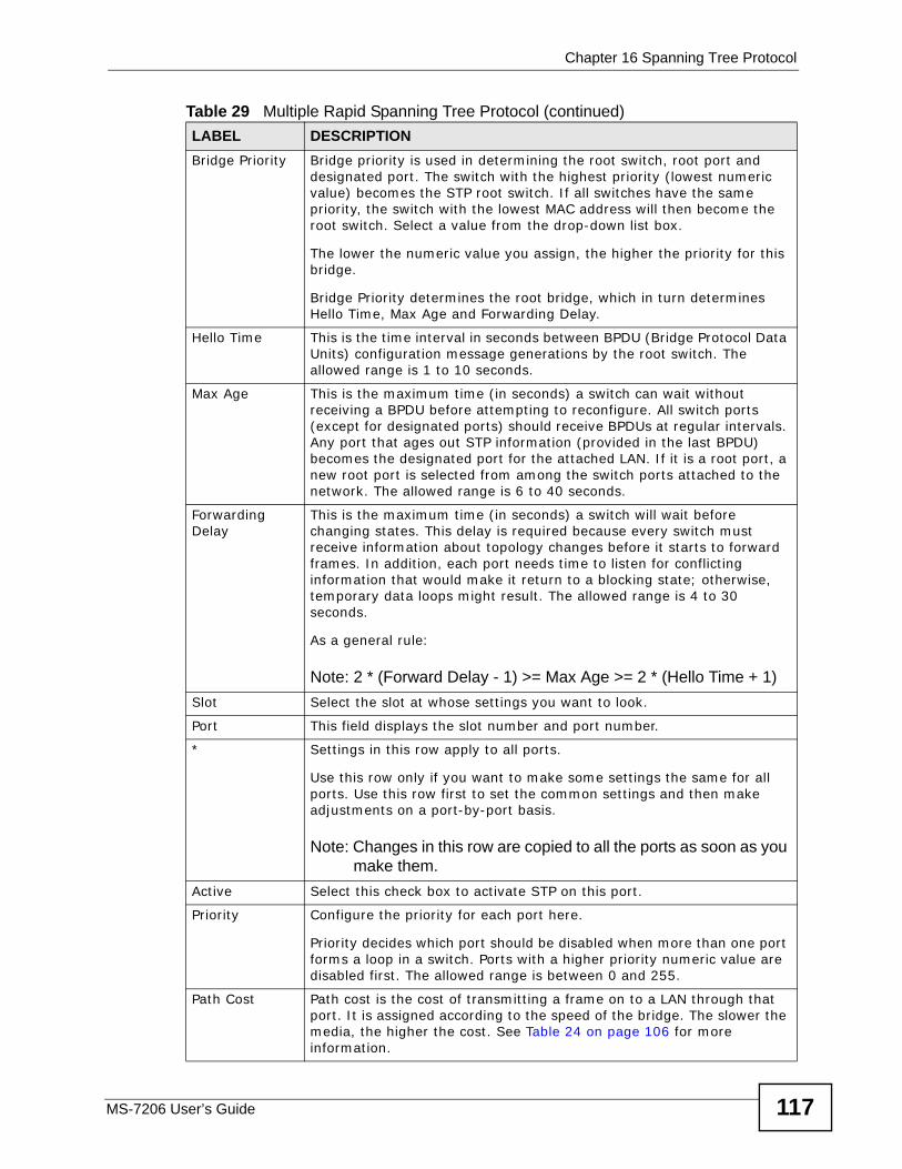
Chapter 16 Spanning Tree Protocol
MS-7206 User’s Guide 117
Bridge Priority Bridge priority is used in determining the root switch, root port and designated port. The switch with the highest priority (lowest numeric value) becomes the STP root switch. If all switches have the same priority, the switch with the lowest MAC address will then become the root switch. Select a value from the drop-down list box.
The lower the numeric value you assign, the higher the priority for this bridge.
Bridge Priority determines the root bridge, which in turn determines Hello Time, Max Age and Forwarding Delay.
Hello Time This is the time interval in seconds between BPDU (Bridge Protocol Data Units) configuration message generations by the root switch. The allowed range is 1 to 10 seconds.
Max Age This is the maximum time (in seconds) a switch can wait without receiving a BPDU before attempting to reconfigure. All switch ports (except for designated ports) should receive BPDUs at regular intervals. Any port that ages out STP information (provided in the last BPDU) becomes the designated port for the attached LAN. If it is a root port, a new root port is selected from among the switch ports attached to the network. The allowed range is 6 to 40 seconds.
Forwarding Delay
This is the maximum time (in seconds) a switch will wait before changing states. This delay is required because every switch must receive information about topology changes before it starts to forward frames. In addition, each port needs time to listen for conflicting information that would make it return to a blocking state; otherwise, temporary data loops might result. The allowed range is 4 to 30 seconds.
As a general rule:
Note: 2 * (Forward Delay - 1) >= Max Age >= 2 * (Hello Time + 1)Slot Select the slot at whose settings you want to look.
Port This field displays the slot number and port number.
* Settings in this row apply to all ports.
Use this row only if you want to make some settings the same for all ports. Use this row first to set the common settings and then make adjustments on a port-by-port basis.
Note: Changes in this row are copied to all the ports as soon as you make them.
Active Select this check box to activate STP on this port.
Priority Configure the priority for each port here.
Priority decides which port should be disabled when more than one port forms a loop in a switch. Ports with a higher priority numeric value are disabled first. The allowed range is between 0 and 255.
Path Cost Path cost is the cost of transmitting a frame on to a LAN through that port. It is assigned according to the speed of the bridge. The slower the media, the higher the cost. See Table 24 on page 106 for more information.
Table 29 Multiple Rapid Spanning Tree Protocol (continued)LABEL DESCRIPTION
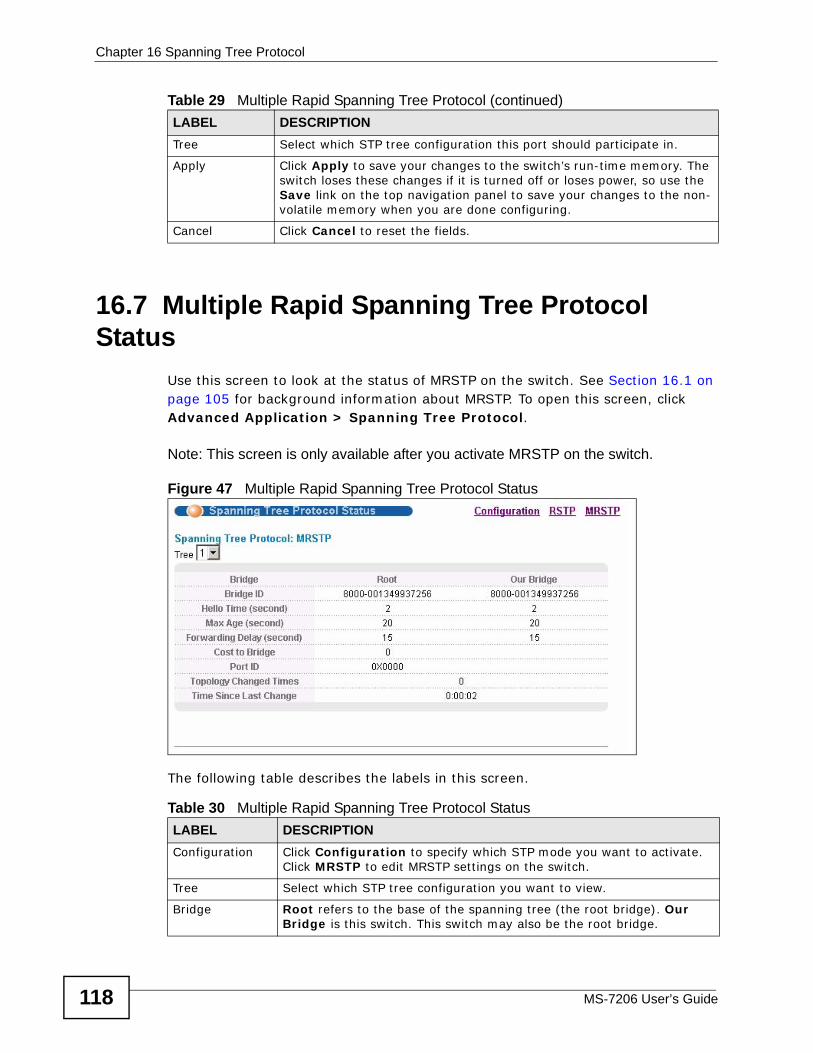
Chapter 16 Spanning Tree Protocol
MS-7206 User’s Guide118
16.7 Multiple Rapid Spanning Tree Protocol Status
Use this screen to look at the status of MRSTP on the switch. See Section 16.1 on page 105 for background information about MRSTP. To open this screen, click Advanced Application > Spanning Tree Protocol.
Note: This screen is only available after you activate MRSTP on the switch.
Figure 47 Multiple Rapid Spanning Tree Protocol Status
The following table describes the labels in this screen.
Tree Select which STP tree configuration this port should participate in.
Apply Click Apply to save your changes to the switch’s run-time memory. The switch loses these changes if it is turned off or loses power, so use the Save link on the top navigation panel to save your changes to the non-volatile memory when you are done configuring.
Cancel Click Cancel to reset the fields.
Table 29 Multiple Rapid Spanning Tree Protocol (continued)LABEL DESCRIPTION
Table 30 Multiple Rapid Spanning Tree Protocol StatusLABEL DESCRIPTIONConfiguration Click Configuration to specify which STP mode you want to activate.
Click MRSTP to edit MRSTP settings on the switch.
Tree Select which STP tree configuration you want to view.
Bridge Root refers to the base of the spanning tree (the root bridge). Our Bridge is this switch. This switch may also be the root bridge.
Chapter 16 Spanning Tree Protocol
MS-7206 User’s Guide 119
Bridge ID This is the unique identifier for this bridge, consisting of bridge priority plus MAC address. This ID is the same for Root and Our Bridge if the switch is the root switch.
Hello Time (second)
This is the time interval (in seconds) at which the root switch transmits a configuration message. The root bridge determines Hello Time, Max Age and Forwarding Delay
Max Age (second)
This is the maximum time (in seconds) a switch can wait without receiving a configuration message before attempting to reconfigure.
Forwarding Delay (second)
This is the time (in seconds) the root switch will wait before changing states (that is, listening to learning to forwarding).
Cost to Bridge This is the path cost from the root port on this switch to the root switch.
Port ID This is the priority and number of the port on the switch through which this switch must communicate with the root of the Spanning Tree.
Topology Changed Times
This is the number of times the spanning tree has been reconfigured.
Time Since Last Change
This is the time since the spanning tree was last reconfigured.
Table 30 Multiple Rapid Spanning Tree Protocol Status (continued)LABEL DESCRIPTION
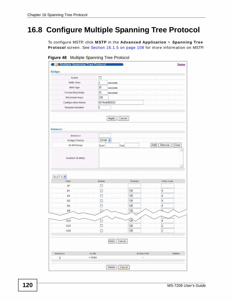
Chapter 16 Spanning Tree Protocol
MS-7206 User’s Guide120
16.8 Configure Multiple Spanning Tree Protocol To configure MSTP, click MSTP in the Advanced Application > Spanning Tree Protocol screen. See Section 16.1.5 on page 108 for more information on MSTP.
Figure 48 Multiple Spanning Tree Protocol
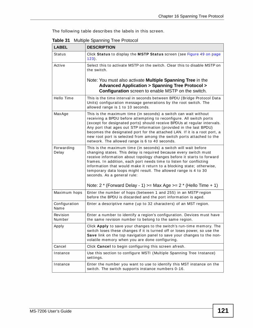
Chapter 16 Spanning Tree Protocol
MS-7206 User’s Guide 121
The following table describes the labels in this screen.
Table 31 Multiple Spanning Tree ProtocolLABEL DESCRIPTIONStatus Click Status to display the MSTP Status screen (see Figure 49 on page
123).
Active Select this to activate MSTP on the switch. Clear this to disable MSTP on the switch.
Note: You must also activate Multiple Spanning Tree in the Advanced Application > Spanning Tree Protocol > Configuration screen to enable MSTP on the switch.
Hello Time This is the time interval in seconds between BPDU (Bridge Protocol Data Units) configuration message generations by the root switch. The allowed range is 1 to 10 seconds.
MaxAge This is the maximum time (in seconds) a switch can wait without receiving a BPDU before attempting to reconfigure. All switch ports (except for designated ports) should receive BPDUs at regular intervals. Any port that ages out STP information (provided in the last BPDU) becomes the designated port for the attached LAN. If it is a root port, a new root port is selected from among the switch ports attached to the network. The allowed range is 6 to 40 seconds.
Forwarding Delay
This is the maximum time (in seconds) a switch will wait before changing states. This delay is required because every switch must receive information about topology changes before it starts to forward frames. In addition, each port needs time to listen for conflicting information that would make it return to a blocking state; otherwise, temporary data loops might result. The allowed range is 4 to 30 seconds. As a general rule:
Note: 2 * (Forward Delay - 1) >= Max Age >= 2 * (Hello Time + 1)Maximum hops Enter the number of hops (between 1 and 255) in an MSTP region
before the BPDU is discarded and the port information is aged.
Configuration Name
Enter a descriptive name (up to 32 characters) of an MST region.
Revision Number
Enter a number to identify a region’s configuration. Devices must have the same revision number to belong to the same region.
Apply Click Apply to save your changes to the switch’s run-time memory. The switch loses these changes if it is turned off or loses power, so use the Save link on the top navigation panel to save your changes to the non-volatile memory when you are done configuring.
Cancel Click Cancel to begin configuring this screen afresh.
Instance Use this section to configure MSTI (Multiple Spanning Tree Instance) settings.
Instance Enter the number you want to use to identify this MST instance on the switch. The switch supports instance numbers 0-16.
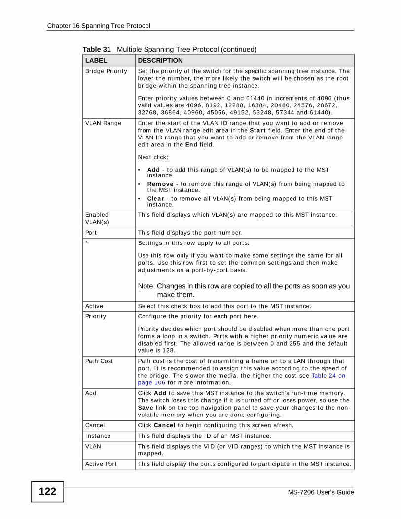
Chapter 16 Spanning Tree Protocol
MS-7206 User’s Guide122
Bridge Priority Set the priority of the switch for the specific spanning tree instance. The lower the number, the more likely the switch will be chosen as the root bridge within the spanning tree instance.
Enter priority values between 0 and 61440 in increments of 4096 (thus valid values are 4096, 8192, 12288, 16384, 20480, 24576, 28672, 32768, 36864, 40960, 45056, 49152, 53248, 57344 and 61440).
VLAN Range Enter the start of the VLAN ID range that you want to add or remove from the VLAN range edit area in the Start field. Enter the end of the VLAN ID range that you want to add or remove from the VLAN range edit area in the End field.
Next click:
• Add - to add this range of VLAN(s) to be mapped to the MST instance.
• Remove - to remove this range of VLAN(s) from being mapped to the MST instance.
• Clear - to remove all VLAN(s) from being mapped to this MST instance.
Enabled VLAN(s)
This field displays which VLAN(s) are mapped to this MST instance.
Port This field displays the port number.
* Settings in this row apply to all ports.
Use this row only if you want to make some settings the same for all ports. Use this row first to set the common settings and then make adjustments on a port-by-port basis.
Note: Changes in this row are copied to all the ports as soon as you make them.
Active Select this check box to add this port to the MST instance.
Priority Configure the priority for each port here.
Priority decides which port should be disabled when more than one port forms a loop in a switch. Ports with a higher priority numeric value are disabled first. The allowed range is between 0 and 255 and the default value is 128.
Path Cost Path cost is the cost of transmitting a frame on to a LAN through that port. It is recommended to assign this value according to the speed of the bridge. The slower the media, the higher the cost-see Table 24 on page 106 for more information.
Add Click Add to save this MST instance to the switch’s run-time memory. The switch loses this change if it is turned off or loses power, so use the Save link on the top navigation panel to save your changes to the non-volatile memory when you are done configuring.
Cancel Click Cancel to begin configuring this screen afresh.
Instance This field displays the ID of an MST instance.
VLAN This field displays the VID (or VID ranges) to which the MST instance is mapped.
Active Port This field display the ports configured to participate in the MST instance.
Table 31 Multiple Spanning Tree Protocol (continued)LABEL DESCRIPTION
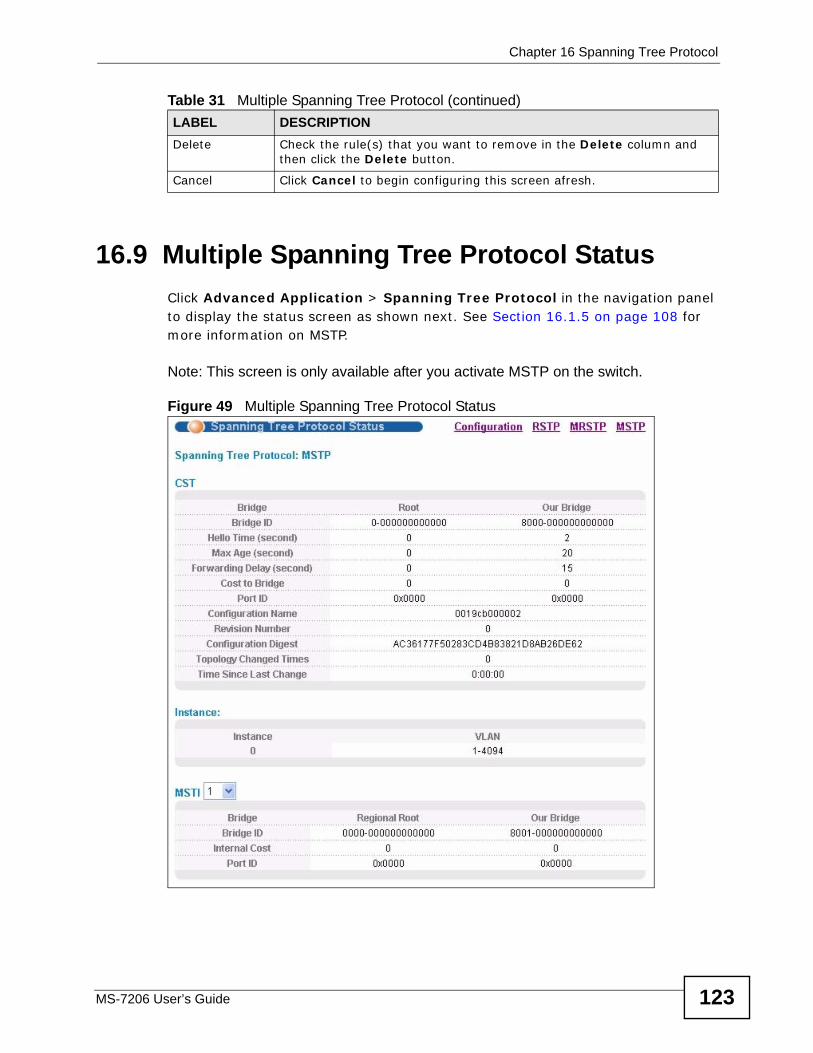
Chapter 16 Spanning Tree Protocol
MS-7206 User’s Guide 123
16.9 Multiple Spanning Tree Protocol Status Click Advanced Application > Spanning Tree Protocol in the navigation panel to display the status screen as shown next. See Section 16.1.5 on page 108 for more information on MSTP.
Note: This screen is only available after you activate MSTP on the switch.
Figure 49 Multiple Spanning Tree Protocol Status
Delete Check the rule(s) that you want to remove in the Delete column and then click the Delete button.
Cancel Click Cancel to begin configuring this screen afresh.
Table 31 Multiple Spanning Tree Protocol (continued)LABEL DESCRIPTION
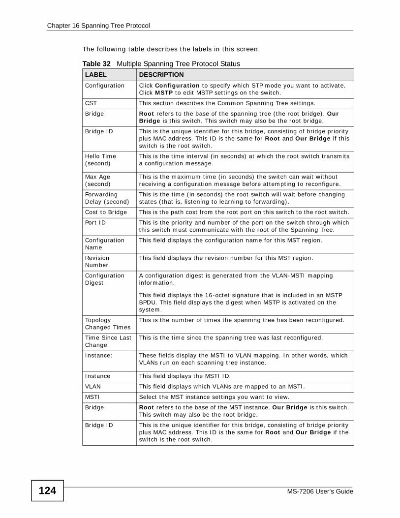
Chapter 16 Spanning Tree Protocol
MS-7206 User’s Guide124
The following table describes the labels in this screen.
Table 32 Multiple Spanning Tree Protocol Status LABEL DESCRIPTIONConfiguration Click Configuration to specify which STP mode you want to activate.
Click MSTP to edit MSTP settings on the switch.
CST This section describes the Common Spanning Tree settings.
Bridge Root refers to the base of the spanning tree (the root bridge). Our Bridge is this switch. This switch may also be the root bridge.
Bridge ID This is the unique identifier for this bridge, consisting of bridge priority plus MAC address. This ID is the same for Root and Our Bridge if this switch is the root switch.
Hello Time (second)
This is the time interval (in seconds) at which the root switch transmits a configuration message.
Max Age (second)
This is the maximum time (in seconds) the switch can wait without receiving a configuration message before attempting to reconfigure.
Forwarding Delay (second)
This is the time (in seconds) the root switch will wait before changing states (that is, listening to learning to forwarding).
Cost to Bridge This is the path cost from the root port on this switch to the root switch.
Port ID This is the priority and number of the port on the switch through which this switch must communicate with the root of the Spanning Tree.
Configuration Name
This field displays the configuration name for this MST region.
Revision Number
This field displays the revision number for this MST region.
Configuration Digest
A configuration digest is generated from the VLAN-MSTI mapping information.
This field displays the 16-octet signature that is included in an MSTP BPDU. This field displays the digest when MSTP is activated on the system.
Topology Changed Times
This is the number of times the spanning tree has been reconfigured.
Time Since Last Change
This is the time since the spanning tree was last reconfigured.
Instance: These fields display the MSTI to VLAN mapping. In other words, which VLANs run on each spanning tree instance.
Instance This field displays the MSTI ID.
VLAN This field displays which VLANs are mapped to an MSTI.
MSTI Select the MST instance settings you want to view.
Bridge Root refers to the base of the MST instance. Our Bridge is this switch. This switch may also be the root bridge.
Bridge ID This is the unique identifier for this bridge, consisting of bridge priority plus MAC address. This ID is the same for Root and Our Bridge if the switch is the root switch.
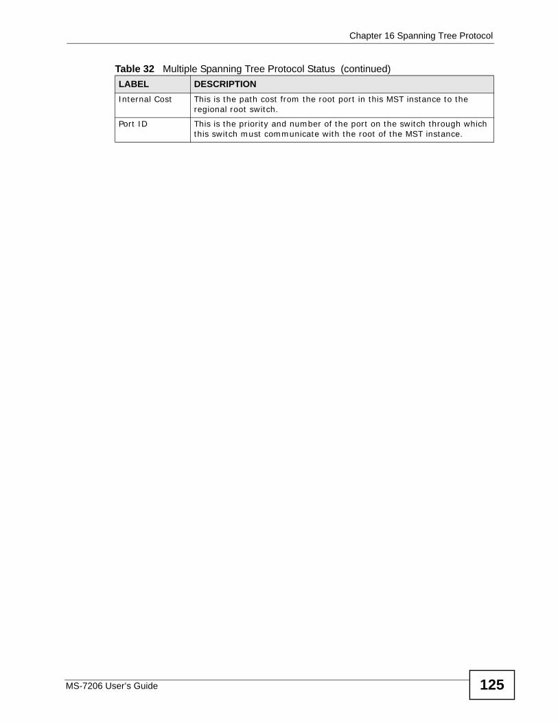
Chapter 16 Spanning Tree Protocol
MS-7206 User’s Guide 125
Internal Cost This is the path cost from the root port in this MST instance to the regional root switch.
Port ID This is the priority and number of the port on the switch through which this switch must communicate with the root of the MST instance.
Table 32 Multiple Spanning Tree Protocol Status (continued)LABEL DESCRIPTION

Chapter 16 Spanning Tree Protocol
MS-7206 User’s Guide126
MS-7206 User’s Guide 127
CHAPTER 17 Bandwidth Control
This chapter introduces Committed Information Rate (CIR) and Peak Information Rate (PIR) and then shows you how to configure the maximum allowable bandwidth for incoming (ingress) and outgoing (egress) traffic flows on a port.
17.1 CIR and PIRThe Committed Information Rate (CIR) is the guaranteed bandwidth for the incoming traffic flow on a port. The Peak Information Rate (PIR) is the maximum bandwidth allowed for the incoming traffic flow on a port when there is no network congestion.
The CIR and PIR should be set for all ports that use the same uplink bandwidth. If the CIR is reached, packets are sent at the rate up to the PIR. When network congestion occurs, packets through the ingress port exceeding the CIR will be marked for drop.
Note: The CIR should be less than the PIR, and the sum of CIRs cannot be greater than or equal to the uplink bandwidth.
17.2 Bandwidth ControlUse this screen to specify the guaranteed bandwidth and maximum bandwidth for incoming (ingress) traffic on a port and to specify the maximum bandwidth for
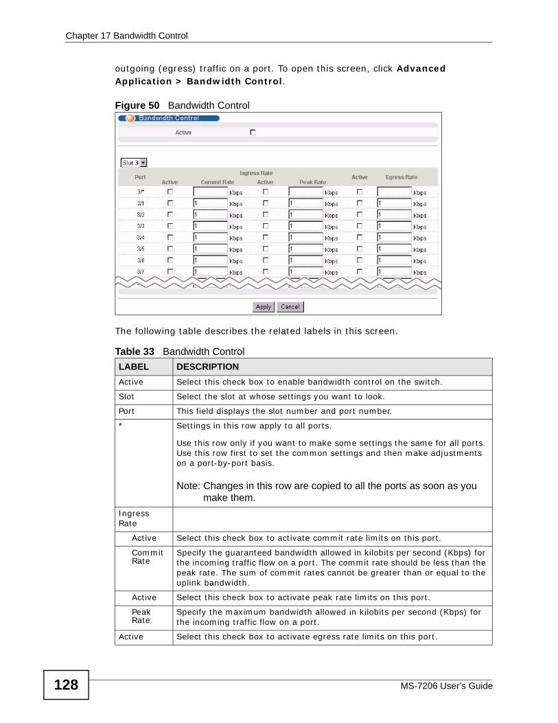
Chapter 17 Bandwidth Control
MS-7206 User’s Guide128
outgoing (egress) traffic on a port. To open this screen, click Advanced Application > Bandwidth Control.
Figure 50 Bandwidth Control
The following table describes the related labels in this screen.
Table 33 Bandwidth ControlLABEL DESCRIPTIONActive Select this check box to enable bandwidth control on the switch.
Slot Select the slot at whose settings you want to look.
Port This field displays the slot number and port number.
* Settings in this row apply to all ports.
Use this row only if you want to make some settings the same for all ports. Use this row first to set the common settings and then make adjustments on a port-by-port basis.
Note: Changes in this row are copied to all the ports as soon as you make them.
Ingress Rate
Active Select this check box to activate commit rate limits on this port.
Commit Rate
Specify the guaranteed bandwidth allowed in kilobits per second (Kbps) for the incoming traffic flow on a port. The commit rate should be less than the peak rate. The sum of commit rates cannot be greater than or equal to the uplink bandwidth.
Active Select this check box to activate peak rate limits on this port.
Peak Rate
Specify the maximum bandwidth allowed in kilobits per second (Kbps) for the incoming traffic flow on a port.
Active Select this check box to activate egress rate limits on this port.
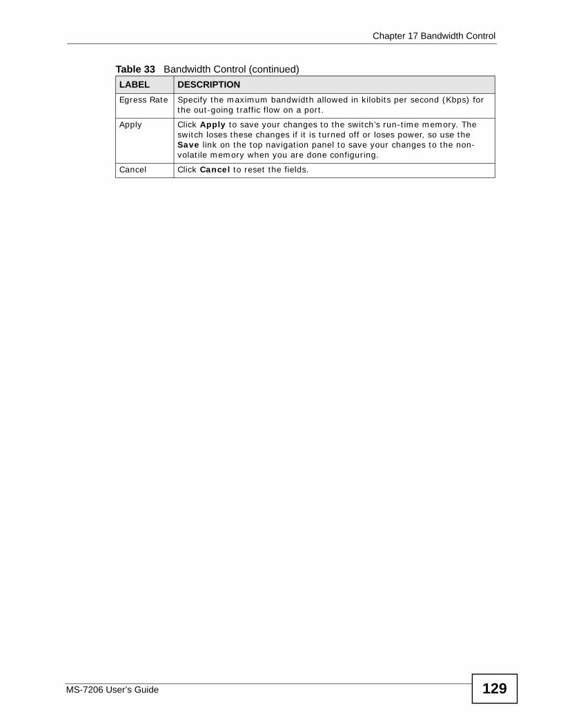
Chapter 17 Bandwidth Control
MS-7206 User’s Guide 129
Egress Rate Specify the maximum bandwidth allowed in kilobits per second (Kbps) for the out-going traffic flow on a port.
Apply Click Apply to save your changes to the switch’s run-time memory. The switch loses these changes if it is turned off or loses power, so use the Save link on the top navigation panel to save your changes to the non-volatile memory when you are done configuring.
Cancel Click Cancel to reset the fields.
Table 33 Bandwidth Control (continued)LABEL DESCRIPTION

Chapter 17 Bandwidth Control
MS-7206 User’s Guide130
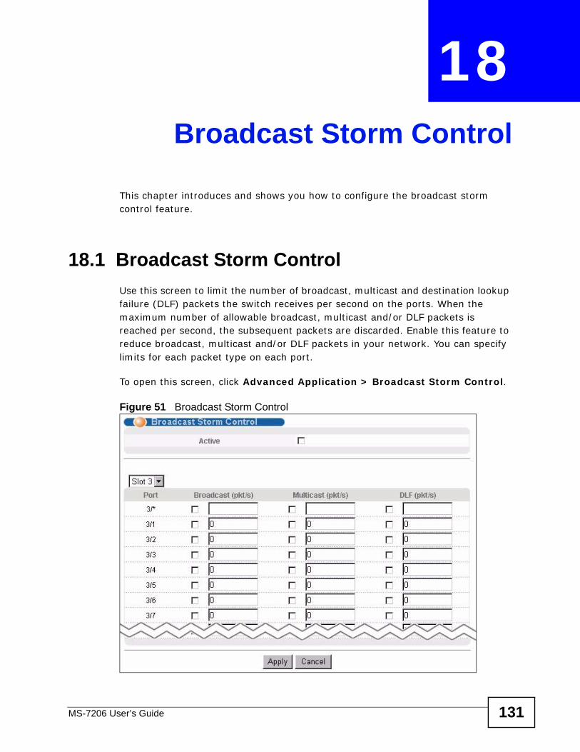
MS-7206 User’s Guide 131
CHAPTER 18 Broadcast Storm Control
This chapter introduces and shows you how to configure the broadcast storm control feature.
18.1 Broadcast Storm ControlUse this screen to limit the number of broadcast, multicast and destination lookup failure (DLF) packets the switch receives per second on the ports. When the maximum number of allowable broadcast, multicast and/or DLF packets is reached per second, the subsequent packets are discarded. Enable this feature to reduce broadcast, multicast and/or DLF packets in your network. You can specify limits for each packet type on each port.
To open this screen, click Advanced Application > Broadcast Storm Control.
Figure 51 Broadcast Storm Control
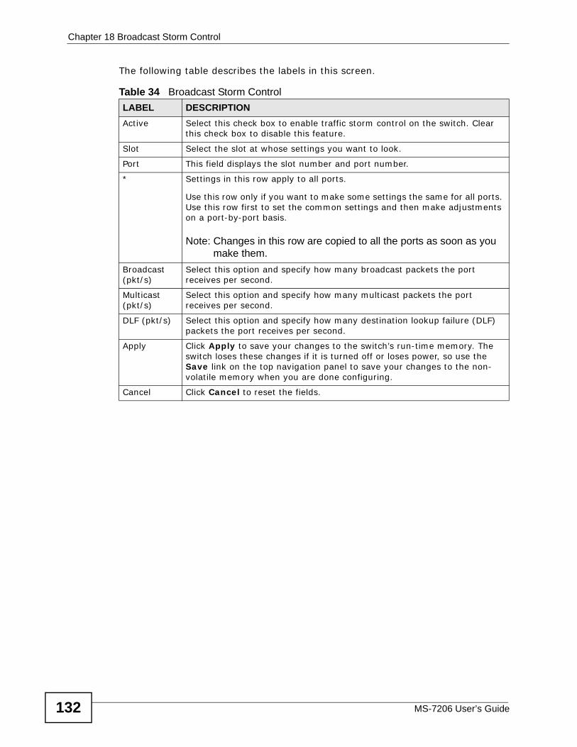
Chapter 18 Broadcast Storm Control
MS-7206 User’s Guide132
The following table describes the labels in this screen.
Table 34 Broadcast Storm Control LABEL DESCRIPTIONActive Select this check box to enable traffic storm control on the switch. Clear
this check box to disable this feature.
Slot Select the slot at whose settings you want to look.
Port This field displays the slot number and port number.
* Settings in this row apply to all ports.
Use this row only if you want to make some settings the same for all ports. Use this row first to set the common settings and then make adjustments on a port-by-port basis.
Note: Changes in this row are copied to all the ports as soon as you make them.
Broadcast (pkt/s)
Select this option and specify how many broadcast packets the port receives per second.
Multicast (pkt/s)
Select this option and specify how many multicast packets the port receives per second.
DLF (pkt/s) Select this option and specify how many destination lookup failure (DLF) packets the port receives per second.
Apply Click Apply to save your changes to the switch’s run-time memory. The switch loses these changes if it is turned off or loses power, so use the Save link on the top navigation panel to save your changes to the non-volatile memory when you are done configuring.
Cancel Click Cancel to reset the fields.
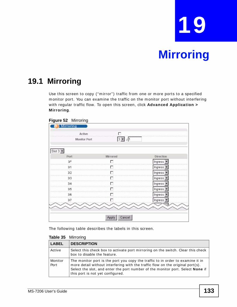
MS-7206 User’s Guide 133
CHAPTER 19 Mirroring
19.1 MirroringUse this screen to copy (“mirror”) traffic from one or more ports to a specified monitor port. You can examine the traffic on the monitor port without interfering with regular traffic flow. To open this screen, click Advanced Application > Mirroring.
Figure 52 Mirroring
The following table describes the labels in this screen.
Table 35 Mirroring LABEL DESCRIPTIONActive Select this check box to activate port mirroring on the switch. Clear this check
box to disable the feature.
Monitor Port
The monitor port is the port you copy the traffic to in order to examine it in more detail without interfering with the traffic flow on the original port(s). Select the slot, and enter the port number of the monitor port. Select None if this port is not yet configured.
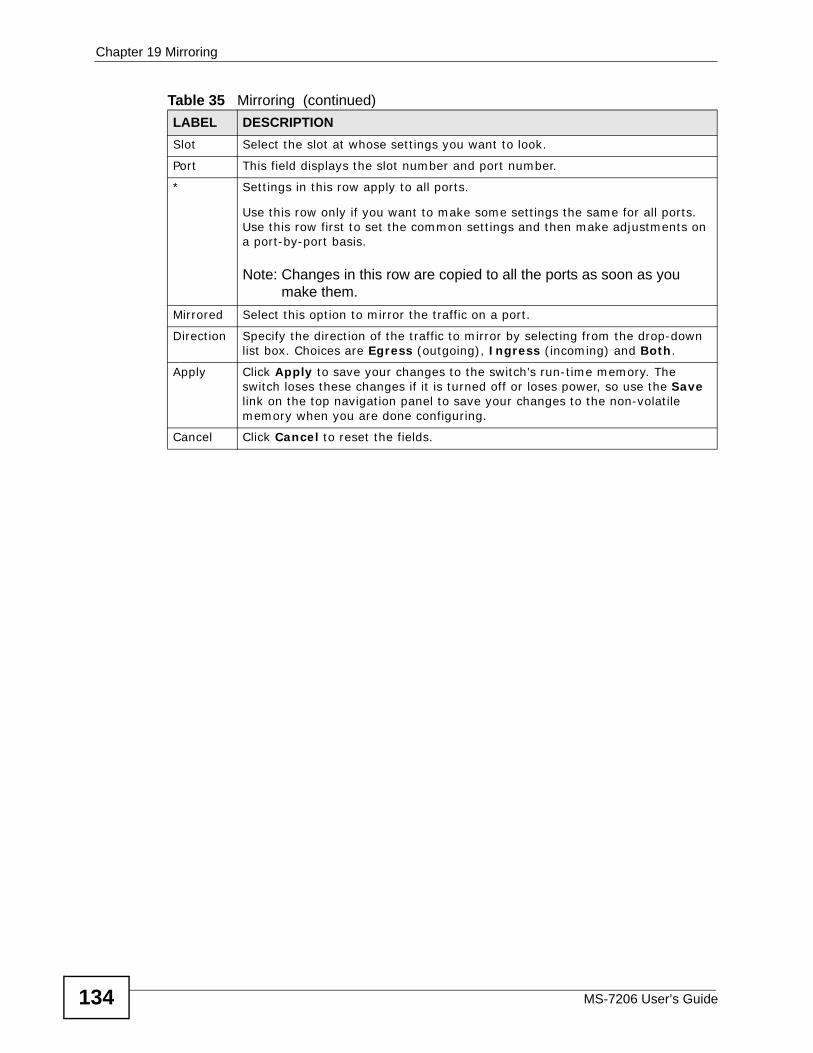
Chapter 19 Mirroring
MS-7206 User’s Guide134
Slot Select the slot at whose settings you want to look.
Port This field displays the slot number and port number.
* Settings in this row apply to all ports.
Use this row only if you want to make some settings the same for all ports. Use this row first to set the common settings and then make adjustments on a port-by-port basis.
Note: Changes in this row are copied to all the ports as soon as you make them.
Mirrored Select this option to mirror the traffic on a port.
Direction Specify the direction of the traffic to mirror by selecting from the drop-down list box. Choices are Egress (outgoing), Ingress (incoming) and Both.
Apply Click Apply to save your changes to the switch’s run-time memory. The switch loses these changes if it is turned off or loses power, so use the Save link on the top navigation panel to save your changes to the non-volatile memory when you are done configuring.
Cancel Click Cancel to reset the fields.
Table 35 Mirroring (continued)LABEL DESCRIPTION
MS-7206 User’s Guide 135
CHAPTER 20 Link Aggregation
This chapter shows you how to logically aggregate physical links to form one logical, higher-bandwidth link.
20.1 Link Aggregation Overview Link aggregation (trunking) is the grouping of physical ports into one logical higher-capacity link. You may want to trunk ports if for example, it is cheaper to use multiple lower-speed links than to under-utilize a high-speed, but more costly, single-port link.
However, the more ports you aggregate then the fewer available ports you have. A trunk group is one logical link containing multiple ports.
The beginning port of each trunk group must be physically connected to form a trunk group.
20.2 Dynamic Link Aggregation The switch adheres to the IEEE 802.3ad standard for static and dynamic (LACP) port trunking.
The switch supports the link aggregation IEEE 802.3ad standard. This standard describes the Link Aggregate Control Protocol (LACP), which is a protocol that dynamically creates and manages trunk groups.
When you enable LACP link aggregation on a port, the port can automatically negotiate with the ports at the remote end of a link to establish trunk groups. LACP also allows port redundancy, that is, if an operational port fails, then one of the “standby” ports become operational without user intervention. Please note that:
• You must connect all ports point-to-point to the same Ethernet switch and configure the ports for LACP trunking.
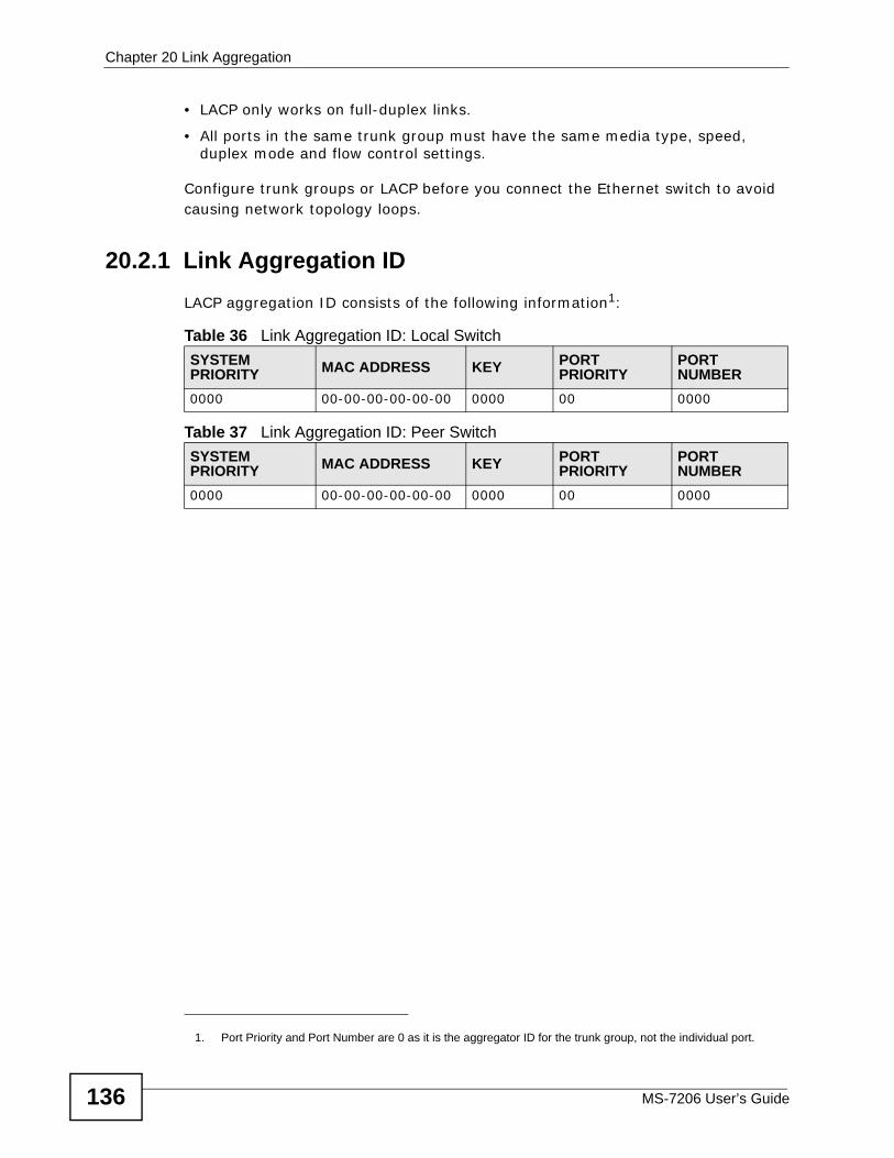
Chapter 20 Link Aggregation
MS-7206 User’s Guide136
• LACP only works on full-duplex links.
• All ports in the same trunk group must have the same media type, speed, duplex mode and flow control settings.
Configure trunk groups or LACP before you connect the Ethernet switch to avoid causing network topology loops.
20.2.1 Link Aggregation ID LACP aggregation ID consists of the following information1:
Table 36 Link Aggregation ID: Local SwitchSYSTEM PRIORITY MAC ADDRESS KEY PORT
PRIORITYPORT NUMBER
0000 00-00-00-00-00-00 0000 00 0000
Table 37 Link Aggregation ID: Peer SwitchSYSTEM PRIORITY MAC ADDRESS KEY PORT
PRIORITYPORT NUMBER
0000 00-00-00-00-00-00 0000 00 0000
1. Port Priority and Port Number are 0 as it is the aggregator ID for the trunk group, not the individual port.
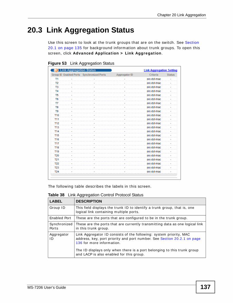
Chapter 20 Link Aggregation
MS-7206 User’s Guide 137
20.3 Link Aggregation Status Use this screen to look at the trunk groups that are on the switch. See Section 20.1 on page 135 for background information about trunk groups. To open this screen, click Advanced Application > Link Aggregation.
Figure 53 Link Aggregation Status
The following table describes the labels in this screen.
Table 38 Link Aggregation Control Protocol StatusLABEL DESCRIPTIONGroup ID This field displays the trunk ID to identify a trunk group, that is, one
logical link containing multiple ports.
Enabled Port These are the ports that are configured to be in the trunk group.
Synchronized Ports
These are the ports that are currently transmitting data as one logical link in this trunk group.
Aggregator ID
Link Aggregator ID consists of the following: system priority, MAC address, key, port priority and port number. See Section 20.2.1 on page 136 for more information.
The ID displays only when there is a port belonging to this trunk group and LACP is also enabled for this group.
Chapter 20 Link Aggregation
MS-7206 User’s Guide138
20.4 Link Aggregation Setting Use this screen to configure trunk groups on the switch. Click Advanced Application > Link Aggregation > Link Aggregation Setting to display the
Criteria This shows the outgoing traffic distribution algorithm used in this trunk group. Packets from the same source and/or to the same destination are sent over the same link within the trunk.
src-mac means the switch distributes traffic based on the packet’s source MAC address.
dst-mac means the switch distributes traffic based on the packet’s destination MAC address.
src-dst-mac means the switch distributes traffic based on a combination of the packet’s source and destination MAC addresses.
src-ip means the switch distributes traffic based on the packet’s source IP address.
dst-ip means the switch distributes traffic based on the packet’s destination IP address.
src-dst-ip means the switch distributes traffic based on a combination of the packet’s source and destination IP addresses.
Status This field displays how these ports were added to the trunk group. It displays:
• Static - if the ports are configured as static members of a trunk group.• LACP - if the ports are configured to join a trunk group via LACP.
Table 38 Link Aggregation Control Protocol Status (continued)LABEL DESCRIPTION
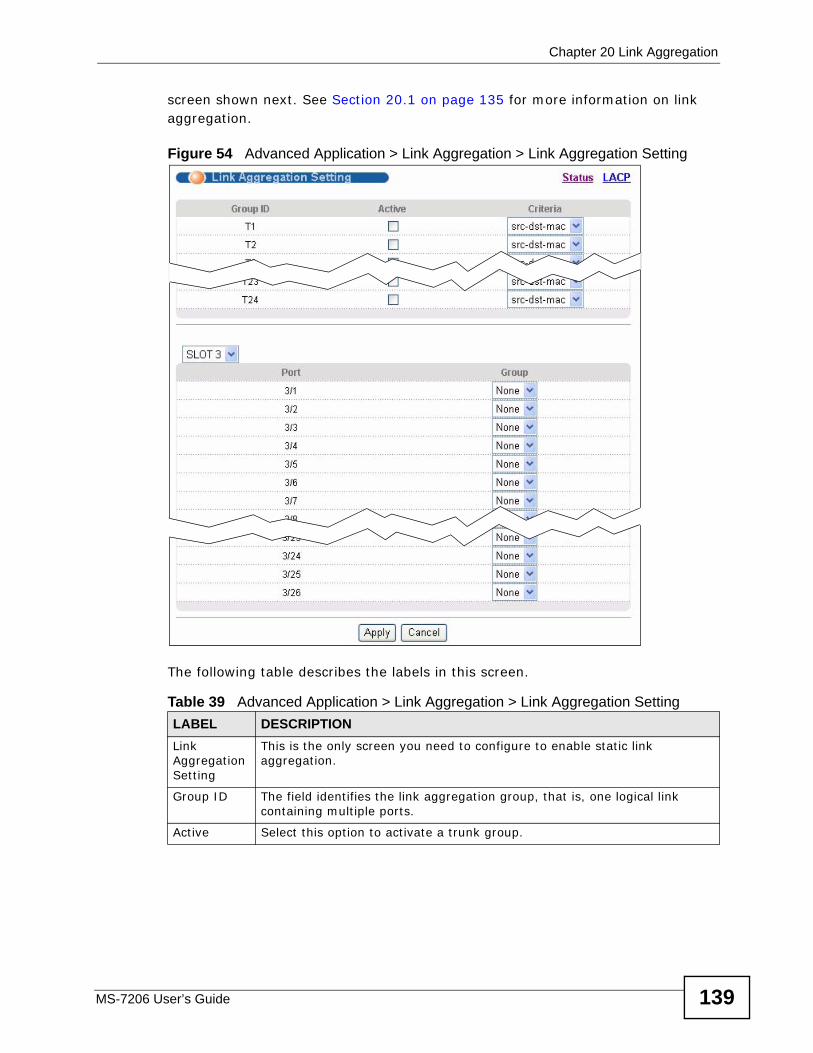
Chapter 20 Link Aggregation
MS-7206 User’s Guide 139
screen shown next. See Section 20.1 on page 135 for more information on link aggregation.
Figure 54 Advanced Application > Link Aggregation > Link Aggregation Setting
The following table describes the labels in this screen.
Table 39 Advanced Application > Link Aggregation > Link Aggregation Setting LABEL DESCRIPTIONLink Aggregation Setting
This is the only screen you need to configure to enable static link aggregation.
Group ID The field identifies the link aggregation group, that is, one logical link containing multiple ports.
Active Select this option to activate a trunk group.
Chapter 20 Link Aggregation
MS-7206 User’s Guide140
20.5 Link Aggregation Control Protocol Use this screen to configure LACP settings on the switch. See Section 20.1 on page 135 for more information on link aggregation. To open this screen, click
Criteria Select the outgoing traffic distribution type. Packets from the same source and/or to the same destination are sent over the same link within the trunk. By default, the switch uses the src-dst-mac distribution type. If the switch is behind a router, the packet’s destination or source MAC address will be changed. In this case, set the switch to distribute traffic based on its IP address to make sure port trunking can work properly.
Select src-mac to distribute traffic based on the packet’s source MAC address.
Select dst-mac to distribute traffic based on the packet’s destination MAC address.
Select src-dst-mac to distribute traffic based on a combination of the packet’s source and destination MAC addresses.
Select src-ip to distribute traffic based on the packet’s source IP address.
Select dst-ip to distribute traffic based on the packet’s destination IP address.
Select src-dst-ip to distribute traffic based on a combination of the packet’s source and destination IP addresses.
Slot Select the slot at whose settings you want to look.
Port This field displays the port number.
Group Select the trunk group to which a port belongs.
Apply Click Apply to save your changes to the switch’s run-time memory. The switch loses these changes if it is turned off or loses power, so use the Save link on the top navigation panel to save your changes to the non-volatile memory when you are done configuring.
Cancel Click Cancel to begin configuring this screen afresh.
Table 39 Advanced Application > Link Aggregation > Link Aggregation Setting LABEL DESCRIPTION
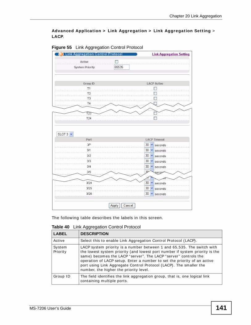
Chapter 20 Link Aggregation
MS-7206 User’s Guide 141
Advanced Application > Link Aggregation > Link Aggregation Setting > LACP.
Figure 55 Link Aggregation Control Protocol
The following table describes the labels in this screen.
Table 40 Link Aggregation Control ProtocolLABEL DESCRIPTIONActive Select this to enable Link Aggregation Control Protocol (LACP).
System Priority
LACP system priority is a number between 1 and 65,535. The switch with the lowest system priority (and lowest port number if system priority is the same) becomes the LACP “server”. The LACP “server” controls the operation of LACP setup. Enter a number to set the priority of an active port using Link Aggregate Control Protocol (LACP). The smaller the number, the higher the priority level.
Group ID The field identifies the link aggregation group, that is, one logical link containing multiple ports.
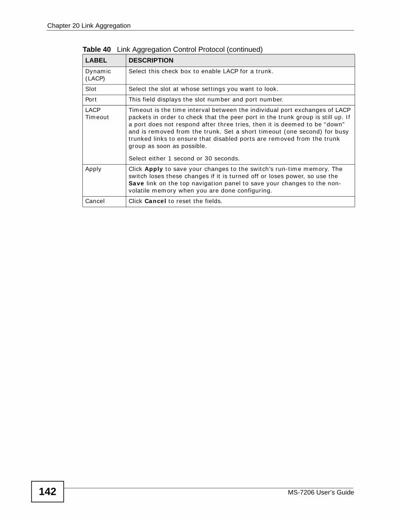
Chapter 20 Link Aggregation
MS-7206 User’s Guide142
Dynamic (LACP)
Select this check box to enable LACP for a trunk.
Slot Select the slot at whose settings you want to look.
Port This field displays the slot number and port number.
LACP Timeout
Timeout is the time interval between the individual port exchanges of LACP packets in order to check that the peer port in the trunk group is still up. If a port does not respond after three tries, then it is deemed to be “down” and is removed from the trunk. Set a short timeout (one second) for busy trunked links to ensure that disabled ports are removed from the trunk group as soon as possible.
Select either 1 second or 30 seconds.
Apply Click Apply to save your changes to the switch’s run-time memory. The switch loses these changes if it is turned off or loses power, so use the Save link on the top navigation panel to save your changes to the non-volatile memory when you are done configuring.
Cancel Click Cancel to reset the fields.
Table 40 Link Aggregation Control Protocol (continued)LABEL DESCRIPTION
MS-7206 User’s Guide 143
CHAPTER 21 Port Authentication
21.1 Port Authentication Overview Port authentication is a way to validate access to ports on the switch to clients based on an external server (authentication server). The switch supports the following methods for port authentication:
• IEEE 802.1x2 - An authentication server validates access to a port based on a username and password provided by the user.
• MAC - An authentication server validates access to a port based on the MAC address and password of the client.
Both types of authentication use the RADIUS (Remote Authentication Dial In User Service, RFC 2138, 2139) protocol to validate users. See Section 28.1.2 on page 196 for more information on configuring your RADIUS server settings.
Note: If you enable IEEE 802.1x authentication and MAC authentication on the same port, the switch performs IEEE 802.1x authentication first. If a user fails to authenticate via the IEEE 802.1x method, then access to the port is denied.
21.1.1 IEEE 802.1x Authentication The following figure illustrates how a client connecting to a IEEE 802.1x authentication enabled port goes through a validation process. The switch prompts the client for login information in the form of a user name and password. When the client provides the login credentials, the switch sends an authentication
2. At the time of writing, IEEE 802.1x is not supported by all operating systems. See your operating system documentation. If your operating system does not support 802.1x, then you may need to install 802.1x client software.
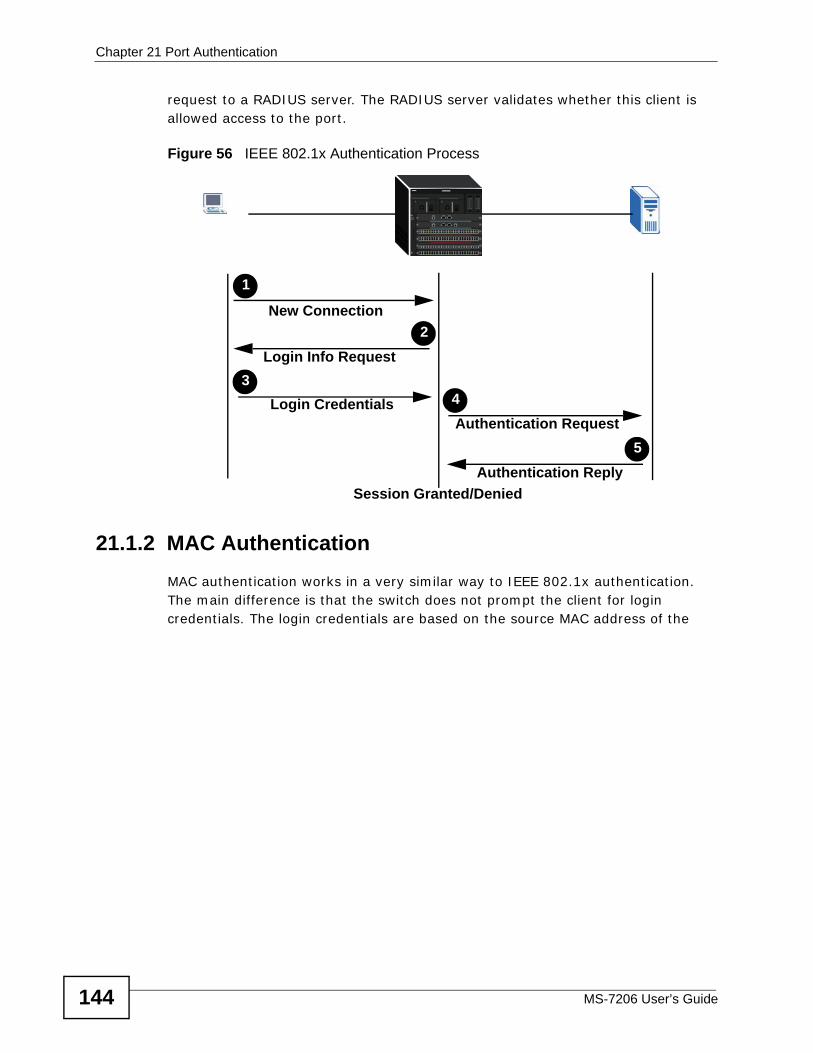
Chapter 21 Port Authentication
MS-7206 User’s Guide144
request to a RADIUS server. The RADIUS server validates whether this client is allowed access to the port.
Figure 56 IEEE 802.1x Authentication Process
21.1.2 MAC Authentication MAC authentication works in a very similar way to IEEE 802.1x authentication. The main difference is that the switch does not prompt the client for login credentials. The login credentials are based on the source MAC address of the
New Connection
Authentication Request
Authentication Reply
1
4
5
Login Credentials
Login Info Request3
2
Session Granted/Denied
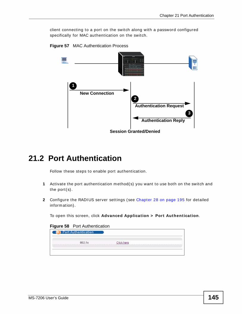
Chapter 21 Port Authentication
MS-7206 User’s Guide 145
client connecting to a port on the switch along with a password configured specifically for MAC authentication on the switch.
Figure 57 MAC Authentication Process
21.2 Port AuthenticationFollow these steps to enable port authentication.
1 Activate the port authentication method(s) you want to use both on the switch and the port(s).
2 Configure the RADIUS server settings (see Chapter 28 on page 195 for detailed information).
To open this screen, click Advanced Application > Port Authentication.
Figure 58 Port Authentication
New Connection
Authentication Request
Authentication Reply
1
2
3
Session Granted/Denied
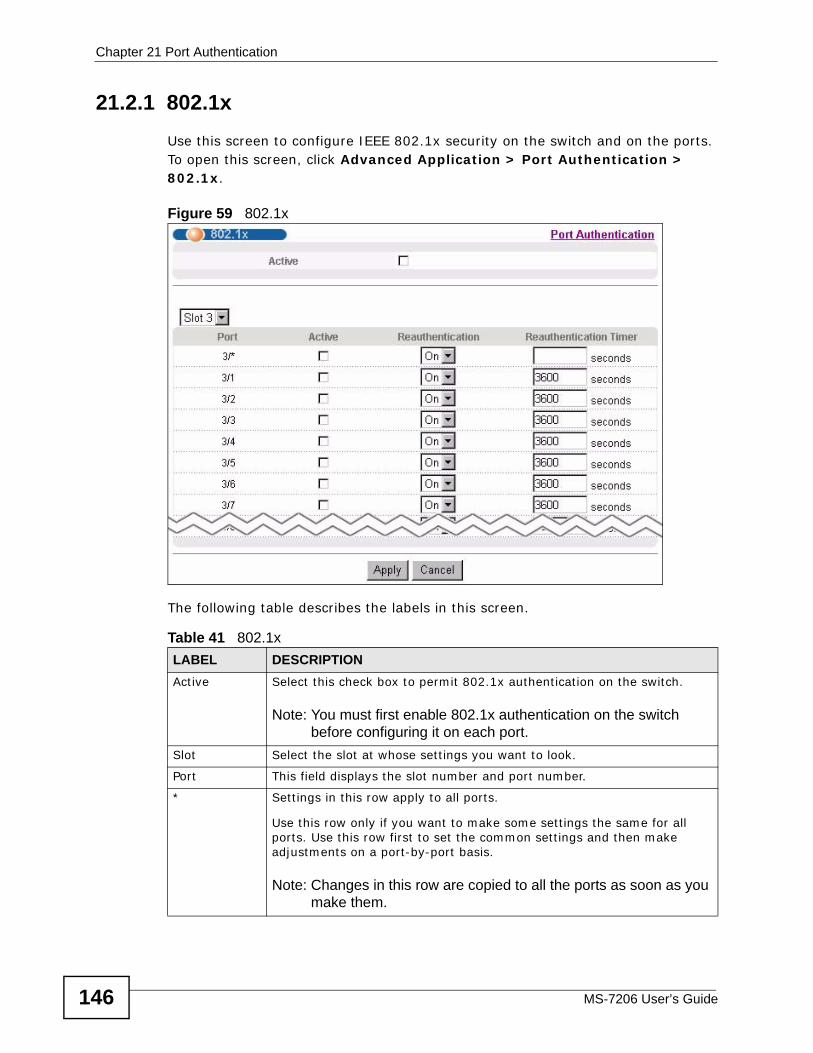
Chapter 21 Port Authentication
MS-7206 User’s Guide146
21.2.1 802.1x Use this screen to configure IEEE 802.1x security on the switch and on the ports. To open this screen, click Advanced Application > Port Authentication > 802.1x.
Figure 59 802.1x
The following table describes the labels in this screen.
Table 41 802.1x LABEL DESCRIPTIONActive Select this check box to permit 802.1x authentication on the switch.
Note: You must first enable 802.1x authentication on the switch before configuring it on each port.
Slot Select the slot at whose settings you want to look.
Port This field displays the slot number and port number.
* Settings in this row apply to all ports.
Use this row only if you want to make some settings the same for all ports. Use this row first to set the common settings and then make adjustments on a port-by-port basis.
Note: Changes in this row are copied to all the ports as soon as you make them.
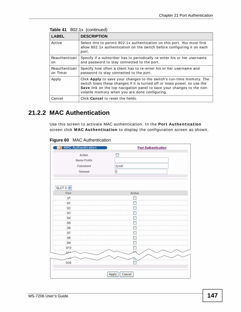
Chapter 21 Port Authentication
MS-7206 User’s Guide 147
21.2.2 MAC Authentication Use this screen to activate MAC authentication. In the Port Authentication screen click MAC Authentication to display the configuration screen as shown.
Figure 60 MAC Authentication
Active Select this to permit 802.1x authentication on this port. You must first allow 802.1x authentication on the switch before configuring it on each port.
Reauthentication
Specify if a subscriber has to periodically re-enter his or her username and password to stay connected to the port.
Reauthentication Timer
Specify how often a client has to re-enter his or her username and password to stay connected to the port.
Apply Click Apply to save your changes to the switch’s run-time memory. The switch loses these changes if it is turned off or loses power, so use the Save link on the top navigation panel to save your changes to the non-volatile memory when you are done configuring.
Cancel Click Cancel to reset the fields.
Table 41 802.1x (continued)LABEL DESCRIPTION
Chapter 21 Port Authentication
MS-7206 User’s Guide148
The following table describes the labels in this screen.
Table 42 MAC Authentication LABEL DESCRIPTIONActive Select this check box to permit MAC authentication on the switch.
Note: You must first enable MAC authentication on the switch before configuring it on each port.
Name Prefix Type the prefix that is appended to all MAC addresses sent to the RADIUS server for authentication. You can enter up to 32 printable ASCII characters.
If you leave this field blank, then only the MAC address of the client is forwarded to the RADIUS server.
Password Type the password the switch sends along with the MAC address of a client for authentication with the RADIUS server. You can enter up to 32 printable ASCII characters.
Timeout Specify the amount of time before the switch allows a client MAC address that fails authentication to try and authenticate again. Maximum time is 3000 seconds.
When a client fails MAC authentication, its MAC address is learned by the MAC address table with a status of denied. The timeout period you specify here is the time the MAC address entry stays in the MAC address table until it is cleared. If you specify 0 for the timeout value, then this entry will not be deleted from the MAC address table.
Note: If the Aging Time in the Switch Setup screen is set to a lower value, then it supersedes this setting. See Section 9.1 on page 69.
Slot Select the slot at whose settings you want to look.
Port This field displays the slot number and port number.
* Use this row to make the setting the same for all ports. Use this row first and then make adjustments on a port-by-port basis.
Note: Changes in this row are copied to all the ports as soon as you make them.
Active Select this to permit MAC authentication on this port. You must first allow MAC authentication on the switch before configuring it on each port.
Apply Click Apply to save your changes to the switch’s run-time memory. The switch loses these changes if it is turned off or loses power, so use the Save link on the top navigation panel to save your changes to the non-volatile memory when you are done configuring.
Cancel Click Cancel to reset the fields.
MS-7206 User’s Guide 149
CHAPTER 22 Port Security
22.1 Port Security Use this screen to allow only packets with dynamically learned MAC addresses and/or configured static MAC addresses to pass through a port on the switch. See Chapter 50 on page 357 for the maximum number of MAC addresses the switch can learn.
For maximum security, enable port security, disable MAC address learning and configure static MAC address(es) for a port. It is not recommended you disable port security together with MAC address learning as this will result in many broadcasts. By default, MAC address learning is still enabled even though the port security is not activated.
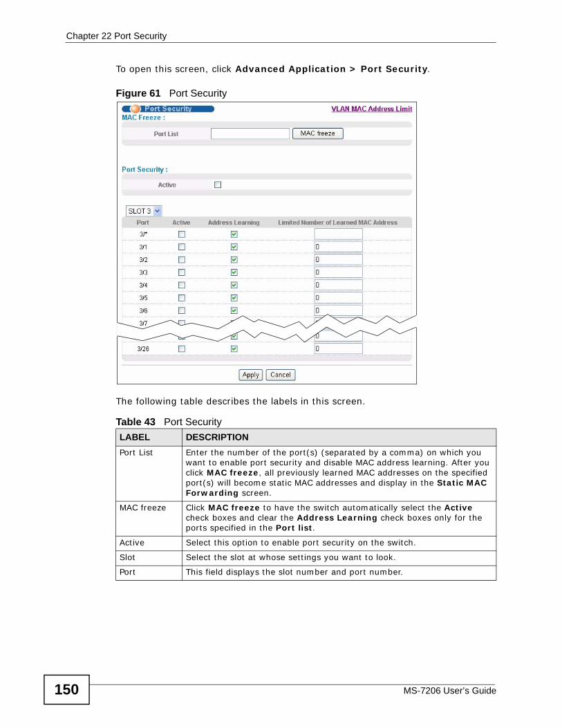
Chapter 22 Port Security
MS-7206 User’s Guide150
To open this screen, click Advanced Application > Port Security.
Figure 61 Port Security
The following table describes the labels in this screen.
Table 43 Port Security LABEL DESCRIPTIONPort List Enter the number of the port(s) (separated by a comma) on which you
want to enable port security and disable MAC address learning. After you click MAC freeze, all previously learned MAC addresses on the specified port(s) will become static MAC addresses and display in the Static MAC Forwarding screen.
MAC freeze Click MAC freeze to have the switch automatically select the Active check boxes and clear the Address Learning check boxes only for the ports specified in the Port list.
Active Select this option to enable port security on the switch.
Slot Select the slot at whose settings you want to look.
Port This field displays the slot number and port number.
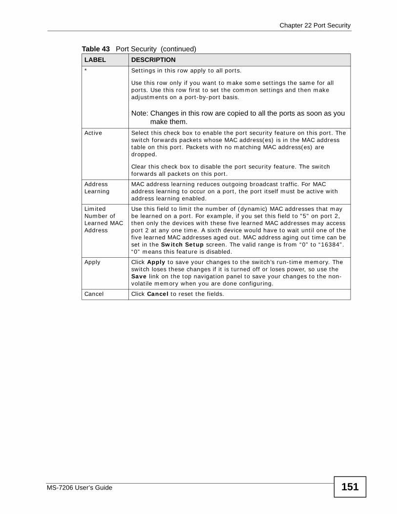
Chapter 22 Port Security
MS-7206 User’s Guide 151
* Settings in this row apply to all ports.
Use this row only if you want to make some settings the same for all ports. Use this row first to set the common settings and then make adjustments on a port-by-port basis.
Note: Changes in this row are copied to all the ports as soon as you make them.
Active Select this check box to enable the port security feature on this port. The switch forwards packets whose MAC address(es) is in the MAC address table on this port. Packets with no matching MAC address(es) are dropped.
Clear this check box to disable the port security feature. The switch forwards all packets on this port.
Address Learning
MAC address learning reduces outgoing broadcast traffic. For MAC address learning to occur on a port, the port itself must be active with address learning enabled.
Limited Number of Learned MAC Address
Use this field to limit the number of (dynamic) MAC addresses that may be learned on a port. For example, if you set this field to "5" on port 2, then only the devices with these five learned MAC addresses may access port 2 at any one time. A sixth device would have to wait until one of the five learned MAC addresses aged out. MAC address aging out time can be set in the Switch Setup screen. The valid range is from “0” to “16384”. “0” means this feature is disabled.
Apply Click Apply to save your changes to the switch’s run-time memory. The switch loses these changes if it is turned off or loses power, so use the Save link on the top navigation panel to save your changes to the non-volatile memory when you are done configuring.
Cancel Click Cancel to reset the fields.
Table 43 Port Security (continued)LABEL DESCRIPTION
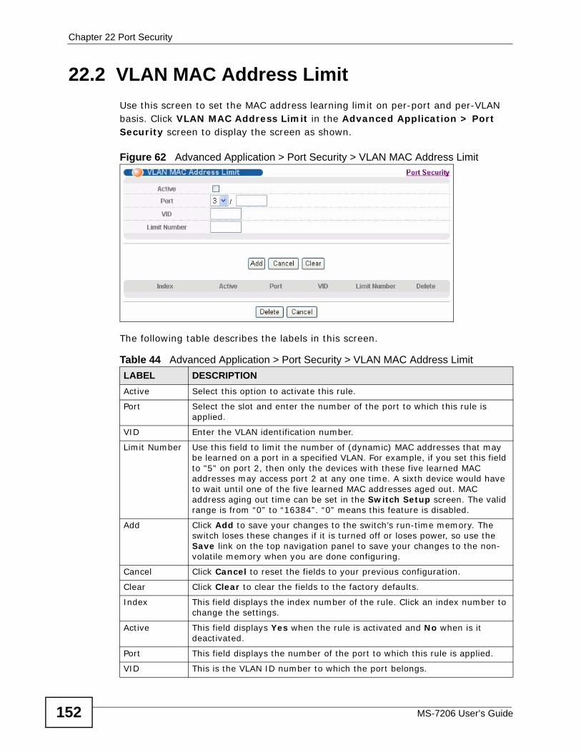
Chapter 22 Port Security
MS-7206 User’s Guide152
22.2 VLAN MAC Address Limit Use this screen to set the MAC address learning limit on per-port and per-VLAN basis. Click VLAN MAC Address Limit in the Advanced Application > Port Security screen to display the screen as shown.
Figure 62 Advanced Application > Port Security > VLAN MAC Address Limit
The following table describes the labels in this screen.
Table 44 Advanced Application > Port Security > VLAN MAC Address Limit LABEL DESCRIPTIONActive Select this option to activate this rule.
Port Select the slot and enter the number of the port to which this rule is applied.
VID Enter the VLAN identification number.
Limit Number Use this field to limit the number of (dynamic) MAC addresses that may be learned on a port in a specified VLAN. For example, if you set this field to "5" on port 2, then only the devices with these five learned MAC addresses may access port 2 at any one time. A sixth device would have to wait until one of the five learned MAC addresses aged out. MAC address aging out time can be set in the Switch Setup screen. The valid range is from “0” to “16384”. “0” means this feature is disabled.
Add Click Add to save your changes to the switch’s run-time memory. The switch loses these changes if it is turned off or loses power, so use the Save link on the top navigation panel to save your changes to the non-volatile memory when you are done configuring.
Cancel Click Cancel to reset the fields to your previous configuration.
Clear Click Clear to clear the fields to the factory defaults.
Index This field displays the index number of the rule. Click an index number to change the settings.
Active This field displays Yes when the rule is activated and No when is it deactivated.
Port This field displays the number of the port to which this rule is applied.
VID This is the VLAN ID number to which the port belongs.
Chapter 22 Port Security
MS-7206 User’s Guide 153
Limit Number This is the maximum number of MAC addresses which a port can learn in a VLAN.
Delete Check the rule(s) that you want to remove in the Delete column and then click the Delete button.
Cancel Click Cancel to clear the selected checkbox(es) in the Delete column.
Table 44 Advanced Application > Port Security > VLAN MAC Address Limit LABEL DESCRIPTION

Chapter 22 Port Security
MS-7206 User’s Guide154
MS-7206 User’s Guide 155
CHAPTER 23 Classifier
This chapter introduces the packet classifier and shows you how to configure it.
23.1 Packet Classifier and QoSQuality of Service (QoS) refers to both a network's ability to deliver data with minimum delay, and the networking methods used to control the use of bandwidth. Without QoS, all traffic data is equally likely to be dropped when the network is congested. This can cause a reduction in network performance and make the network inadequate for time-critical application such as video-on-demand.
A classifier groups traffic into data flows according to specific criteria such as the source address, destination address, source port number, destination port number or incoming port number. For example, you can configure a classifier to select traffic from the same protocol port (such as Telnet) to form a flow.
Configure QoS on the switch to group and prioritize application traffic and fine-tune network performance. Setting up QoS involves two separate steps:
1 Configure classifiers to sort traffic into different flows.
2 Configure policy rules to define actions to be performed for a classified traffic flow (refer to Chapter 24 on page 161 to configure policy rules).
23.2 Classifier Use this screen to configure classifiers for traffic. After you configure the classifier, you can specify actions (“policies”) for traffic that matches the rules. See Chapter 24 on page 161 for more information about policies. To open this screen, click Advanced Application > Classifier.
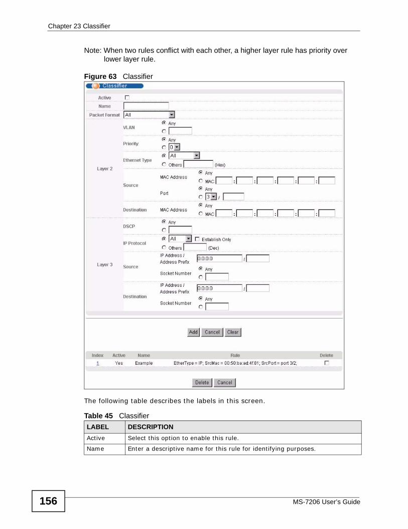
Chapter 23 Classifier
MS-7206 User’s Guide156
Note: When two rules conflict with each other, a higher layer rule has priority over lower layer rule.
Figure 63 Classifier
The following table describes the labels in this screen.
Table 45 Classifier LABEL DESCRIPTIONActive Select this option to enable this rule.
Name Enter a descriptive name for this rule for identifying purposes.
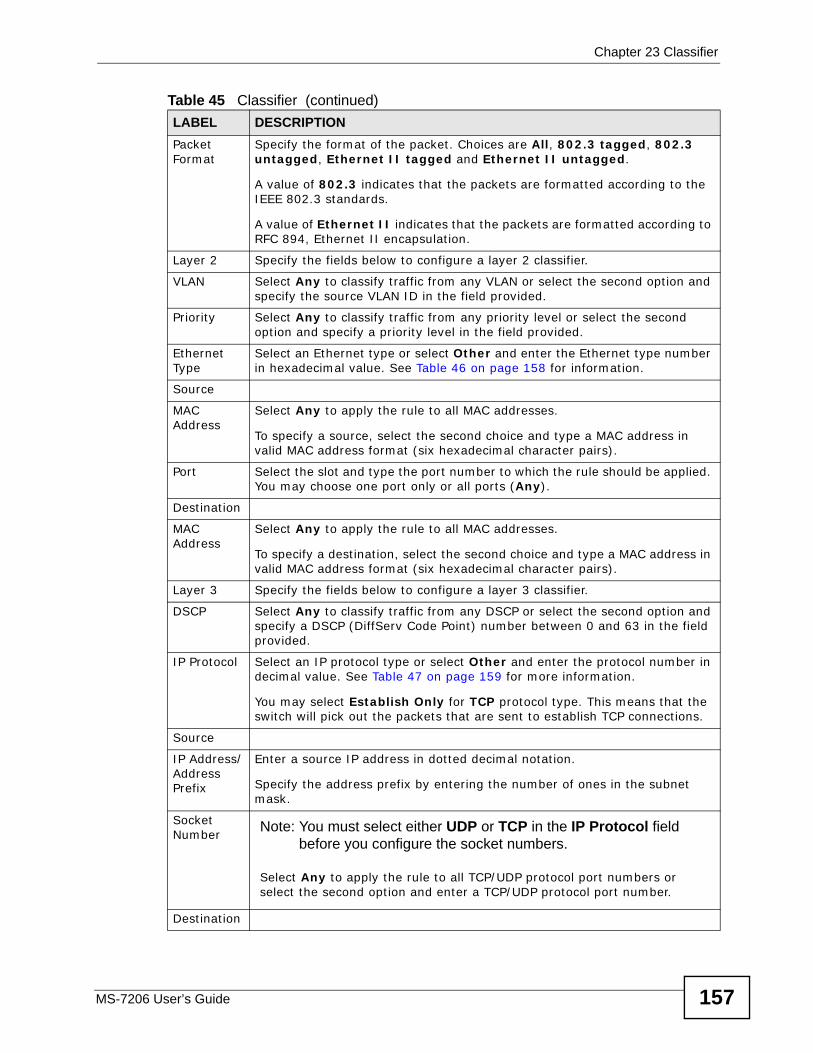
Chapter 23 Classifier
MS-7206 User’s Guide 157
Packet Format
Specify the format of the packet. Choices are All, 802.3 tagged, 802.3 untagged, Ethernet II tagged and Ethernet II untagged.
A value of 802.3 indicates that the packets are formatted according to the IEEE 802.3 standards.
A value of Ethernet II indicates that the packets are formatted according to RFC 894, Ethernet II encapsulation.
Layer 2 Specify the fields below to configure a layer 2 classifier.
VLAN Select Any to classify traffic from any VLAN or select the second option and specify the source VLAN ID in the field provided.
Priority Select Any to classify traffic from any priority level or select the second option and specify a priority level in the field provided.
Ethernet Type
Select an Ethernet type or select Other and enter the Ethernet type number in hexadecimal value. See Table 46 on page 158 for information.
Source
MAC Address
Select Any to apply the rule to all MAC addresses.
To specify a source, select the second choice and type a MAC address in valid MAC address format (six hexadecimal character pairs).
Port Select the slot and type the port number to which the rule should be applied. You may choose one port only or all ports (Any).
Destination
MAC Address
Select Any to apply the rule to all MAC addresses.
To specify a destination, select the second choice and type a MAC address in valid MAC address format (six hexadecimal character pairs).
Layer 3 Specify the fields below to configure a layer 3 classifier.
DSCP Select Any to classify traffic from any DSCP or select the second option and specify a DSCP (DiffServ Code Point) number between 0 and 63 in the field provided.
IP Protocol Select an IP protocol type or select Other and enter the protocol number in decimal value. See Table 47 on page 159 for more information.
You may select Establish Only for TCP protocol type. This means that the switch will pick out the packets that are sent to establish TCP connections.
Source
IP Address/Address Prefix
Enter a source IP address in dotted decimal notation.
Specify the address prefix by entering the number of ones in the subnet mask.
Socket Number
Note: You must select either UDP or TCP in the IP Protocol field before you configure the socket numbers.
Select Any to apply the rule to all TCP/UDP protocol port numbers or select the second option and enter a TCP/UDP protocol port number.
Destination
Table 45 Classifier (continued)LABEL DESCRIPTION
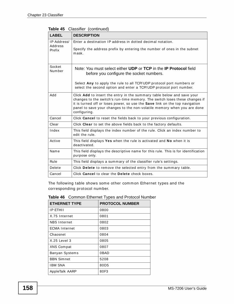
Chapter 23 Classifier
MS-7206 User’s Guide158
The following table shows some other common Ethernet types and the corresponding protocol number.
IP Address/Address Prefix
Enter a destination IP address in dotted decimal notation.
Specify the address prefix by entering the number of ones in the subnet mask.
Socket Number
Note: You must select either UDP or TCP in the IP Protocol field before you configure the socket numbers.
Select Any to apply the rule to all TCP/UDP protocol port numbers or select the second option and enter a TCP/UDP protocol port number.
Add Click Add to insert the entry in the summary table below and save your changes to the switch’s run-time memory. The switch loses these changes if it is turned off or loses power, so use the Save link on the top navigation panel to save your changes to the non-volatile memory when you are done configuring.
Cancel Click Cancel to reset the fields back to your previous configuration.
Clear Click Clear to set the above fields back to the factory defaults.
Index This field displays the index number of the rule. Click an index number to edit the rule.
Active This field displays Yes when the rule is activated and No when it is deactivated.
Name This field displays the descriptive name for this rule. This is for identification purpose only.
Rule This field displays a summary of the classifier rule’s settings.
Delete Click Delete to remove the selected entry from the summary table.
Cancel Click Cancel to clear the Delete check boxes.
Table 46 Common Ethernet Types and Protocol NumberETHERNET TYPE PROTOCOL NUMBERIP ETHII 0800
X.75 Internet 0801
NBS Internet 0802
ECMA Internet 0803
Chaosnet 0804
X.25 Level 3 0805
XNS Compat 0807
Banyan Systems 0BAD
BBN Simnet 5208
IBM SNA 80D5
AppleTalk AARP 80F3
Table 45 Classifier (continued)LABEL DESCRIPTION
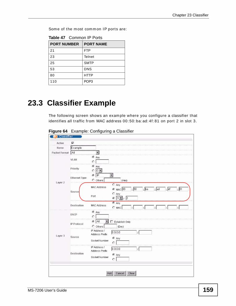
Chapter 23 Classifier
MS-7206 User’s Guide 159
Some of the most common IP ports are:
23.3 Classifier ExampleThe following screen shows an example where you configure a classifier that identifies all traffic from MAC address 00:50:ba:ad:4f:81 on port 2 in slot 3.
Figure 64 Example: Configuring a Classifier
Table 47 Common IP PortsPORT NUMBER PORT NAME21 FTP
23 Telnet
25 SMTP
53 DNS
80 HTTP
110 POP3
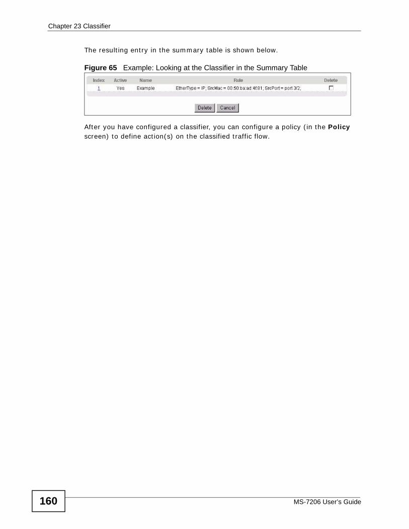
Chapter 23 Classifier
MS-7206 User’s Guide160
The resulting entry in the summary table is shown below.
Figure 65 Example: Looking at the Classifier in the Summary Table
After you have configured a classifier, you can configure a policy (in the Policy screen) to define action(s) on the classified traffic flow.
MS-7206 User’s Guide 161
CHAPTER 24 Policy Rule
This chapter introduces policy rules and shows you how to configure them.
24.1 Policy Rules Overview A classifier distinguishes traffic into flows based on the configured criteria. A policy rule ensures that a traffic flow gets the requested treatment in the network. See Chapter 23 on page 155 for more information about classifiers.
24.1.1 DiffServDiffServ (Differentiated Services) is a class of service (CoS) model that marks packets so that they receive specific per-hop treatment at DiffServ-compliant network devices along the route based on the application types and traffic flow. Packets are marked with DiffServ Code Points (DSCPs) indicating the level of service desired. This allows the intermediary DiffServ-compliant network devices to handle the packets differently depending on the code points without the need to negotiate paths or remember state information for every flow. In addition, applications do not have to request a particular service or give advanced notice of where the traffic is going.
24.1.2 DSCP and Per-Hop Behavior DiffServ defines a new DS (Differentiated Services) field to replace the Type of Service (TOS) field in the IP header. The DS field contains a 2-bit unused field and a 6-bit DSCP field which can define up to 64 service levels. The following figure illustrates the DS field.
DSCP is backward compatible with the three precedence bits in the ToS octet so that non-DiffServ compliant, ToS-enabled network device will not conflict with the DSCP mapping.
DSCP (6 bits) Unused (2 bits)
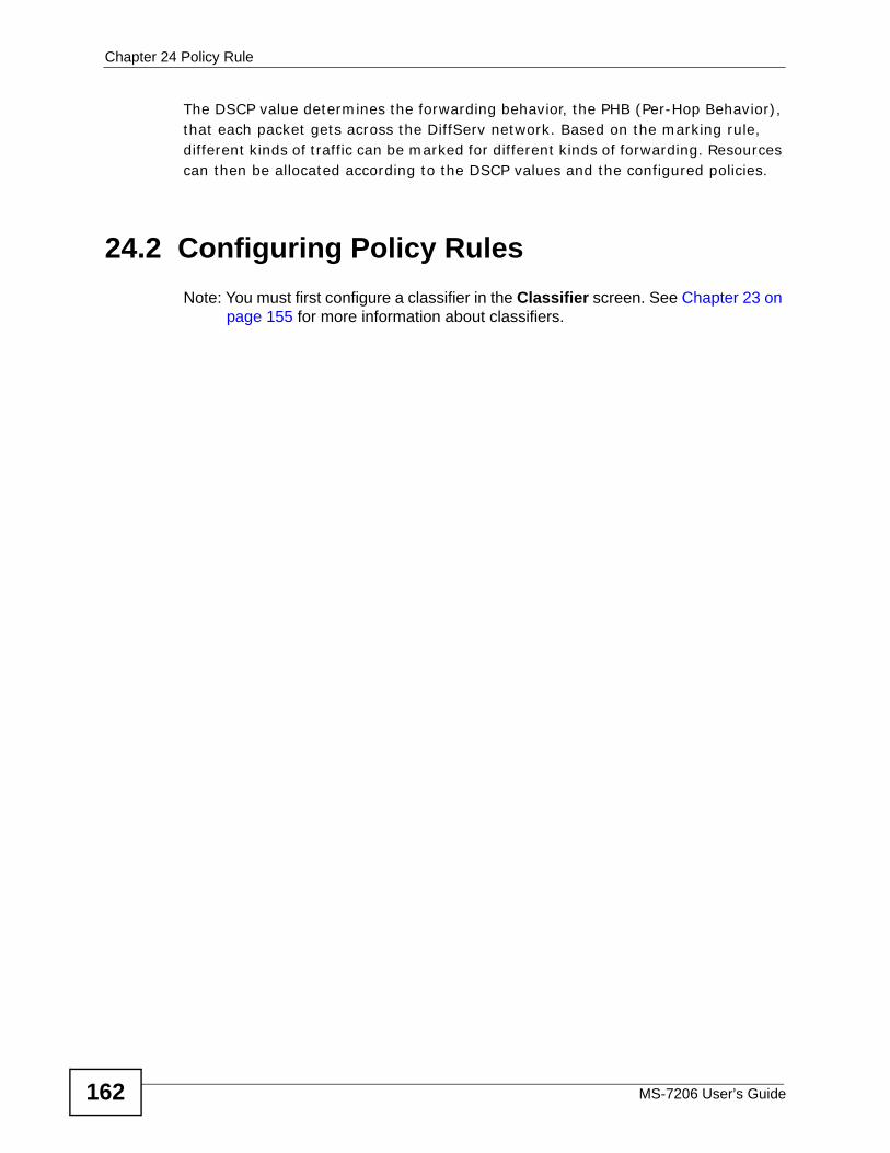
Chapter 24 Policy Rule
MS-7206 User’s Guide162
The DSCP value determines the forwarding behavior, the PHB (Per-Hop Behavior), that each packet gets across the DiffServ network. Based on the marking rule, different kinds of traffic can be marked for different kinds of forwarding. Resources can then be allocated according to the DSCP values and the configured policies.
24.2 Configuring Policy Rules Note: You must first configure a classifier in the Classifier screen. See Chapter 23 on
page 155 for more information about classifiers.
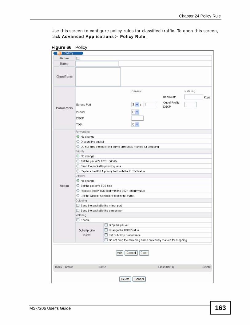
Chapter 24 Policy Rule
MS-7206 User’s Guide 163
Use this screen to configure policy rules for classified traffic. To open this screen, click Advanced Applications > Policy Rule.
Figure 66 Policy
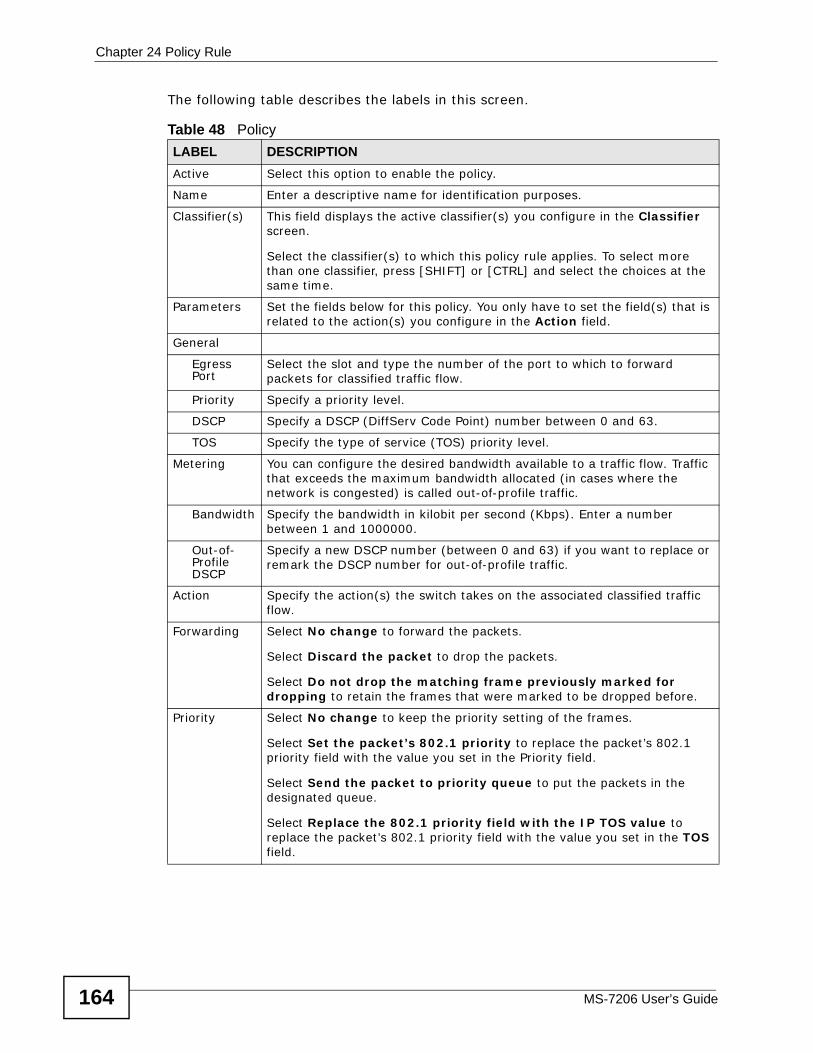
Chapter 24 Policy Rule
MS-7206 User’s Guide164
The following table describes the labels in this screen.
Table 48 Policy LABEL DESCRIPTIONActive Select this option to enable the policy.
Name Enter a descriptive name for identification purposes.
Classifier(s) This field displays the active classifier(s) you configure in the Classifier screen.
Select the classifier(s) to which this policy rule applies. To select more than one classifier, press [SHIFT] or [CTRL] and select the choices at the same time.
Parameters Set the fields below for this policy. You only have to set the field(s) that is related to the action(s) you configure in the Action field.
General
Egress Port
Select the slot and type the number of the port to which to forward packets for classified traffic flow.
Priority Specify a priority level.
DSCP Specify a DSCP (DiffServ Code Point) number between 0 and 63.
TOS Specify the type of service (TOS) priority level.
Metering You can configure the desired bandwidth available to a traffic flow. Traffic that exceeds the maximum bandwidth allocated (in cases where the network is congested) is called out-of-profile traffic.
Bandwidth Specify the bandwidth in kilobit per second (Kbps). Enter a number between 1 and 1000000.
Out-of-Profile DSCP
Specify a new DSCP number (between 0 and 63) if you want to replace or remark the DSCP number for out-of-profile traffic.
Action Specify the action(s) the switch takes on the associated classified traffic flow.
Forwarding Select No change to forward the packets.
Select Discard the packet to drop the packets.
Select Do not drop the matching frame previously marked for dropping to retain the frames that were marked to be dropped before.
Priority Select No change to keep the priority setting of the frames.
Select Set the packet’s 802.1 priority to replace the packet’s 802.1 priority field with the value you set in the Priority field.
Select Send the packet to priority queue to put the packets in the designated queue.
Select Replace the 802.1 priority field with the IP TOS value to replace the packet’s 802.1 priority field with the value you set in the TOS field.
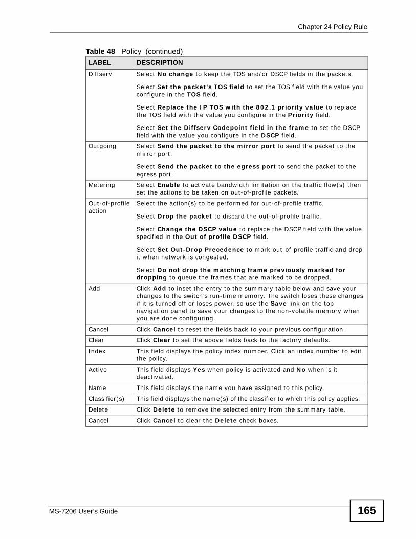
Chapter 24 Policy Rule
MS-7206 User’s Guide 165
Diffserv Select No change to keep the TOS and/or DSCP fields in the packets.
Select Set the packet’s TOS field to set the TOS field with the value you configure in the TOS field.
Select Replace the IP TOS with the 802.1 priority value to replace the TOS field with the value you configure in the Priority field.
Select Set the Diffserv Codepoint field in the frame to set the DSCP field with the value you configure in the DSCP field.
Outgoing Select Send the packet to the mirror port to send the packet to the mirror port.
Select Send the packet to the egress port to send the packet to the egress port.
Metering Select Enable to activate bandwidth limitation on the traffic flow(s) then set the actions to be taken on out-of-profile packets.
Out-of-profile action
Select the action(s) to be performed for out-of-profile traffic.
Select Drop the packet to discard the out-of-profile traffic.
Select Change the DSCP value to replace the DSCP field with the value specified in the Out of profile DSCP field.
Select Set Out-Drop Precedence to mark out-of-profile traffic and drop it when network is congested.
Select Do not drop the matching frame previously marked for dropping to queue the frames that are marked to be dropped.
Add Click Add to inset the entry to the summary table below and save your changes to the switch’s run-time memory. The switch loses these changes if it is turned off or loses power, so use the Save link on the top navigation panel to save your changes to the non-volatile memory when you are done configuring.
Cancel Click Cancel to reset the fields back to your previous configuration.
Clear Click Clear to set the above fields back to the factory defaults.
Index This field displays the policy index number. Click an index number to edit the policy.
Active This field displays Yes when policy is activated and No when is it deactivated.
Name This field displays the name you have assigned to this policy.
Classifier(s) This field displays the name(s) of the classifier to which this policy applies.
Delete Click Delete to remove the selected entry from the summary table.
Cancel Click Cancel to clear the Delete check boxes.
Table 48 Policy (continued)LABEL DESCRIPTION
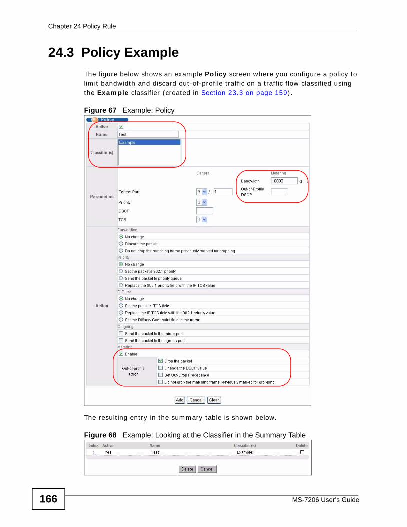
Chapter 24 Policy Rule
MS-7206 User’s Guide166
24.3 Policy ExampleThe figure below shows an example Policy screen where you configure a policy to limit bandwidth and discard out-of-profile traffic on a traffic flow classified using the Example classifier (created in Section 23.3 on page 159).
Figure 67 Example: Policy
The resulting entry in the summary table is shown below.
Figure 68 Example: Looking at the Classifier in the Summary Table

Chapter 24 Policy Rule
MS-7206 User’s Guide 167

Chapter 24 Policy Rule
MS-7206 User’s Guide168
MS-7206 User’s Guide 169
CHAPTER 25 Queuing Method
This chapter introduces the queuing methods supported and then explains the screen for configuring them.
25.1 Queuing Method Overview Queuing is used to help solve performance degradation when there is network congestion. Use the Queuing Method screen to configure queuing algorithms for outgoing traffic. See also Priority Queue Assignment in Switch Setup (Chapter 9 on page 69) and 802.1p Priority in Port Setup (Chapter 12 on page 79) for related information.
Queuing algorithms allow switches to maintain separate queues for packets from each individual source or flow and prevent a source from monopolizing the bandwidth.
25.1.1 Strictly Priority QueuingStrictly Priority Queuing (SPQ) services queues based on priority only. As traffic comes into the switch, traffic on the highest priority queue, Q7 is transmitted first. When that queue empties, traffic on the next highest-priority queue, Q6 is transmitted until Q6 empties, and then traffic is transmitted on Q5 and so on. If higher priority queues never empty, then traffic on lower priority queues never gets sent. SPQ does not automatically adapt to changing network requirements.
25.1.2 Weighted Round Robin Scheduling (WRR) Round Robin Scheduling services queues on a rotating basis and is activated only when a port has more traffic than it can handle. A queue is a given an amount of bandwidth irrespective of the incoming traffic on that port. This queue then moves to the back of the list. The next queue is given an equal amount of bandwidth, and then moves to the end of the list; and so on, depending on the number of queues being used. This works in a looping fashion until a queue is empty.

Chapter 25 Queuing Method
MS-7206 User’s Guide170
Weighted Round Robin Scheduling (WRR) uses the same algorithm as round robin scheduling, but services queues based on their priority and queue weight (the number you configure in the queue Weight field) rather than a fixed amount of bandwidth. WRR is activated only when a port has more traffic than it can handle. Queues with larger weights get more service than queues with smaller weights. This queuing mechanism is highly efficient in that it divides any available bandwidth across the different traffic queues and returns to queues that have not yet emptied.
25.1.3 Weighted Fair QueuingWeighted Fair Queuing (WFQ) is used to guarantee each queue’s minimum bandwidth based on its bandwidth weight (portion) when there is traffic congestion. WFQ is activated only when a port has more traffic than it can handle. Queues with larger weights get more guaranteed bandwidth than queues with smaller weights. This queuing mechanism is highly efficient in that it divides any available bandwidth across the different traffic queues. By default, the weight for Q0 is 1, for Q1 is 2, for Q2 is 3, and so on. Guaranteed bandwidth is calculated as follows:
For example, using the default setting, Q0 on Port 1 gets a guaranteed bandwidth of:
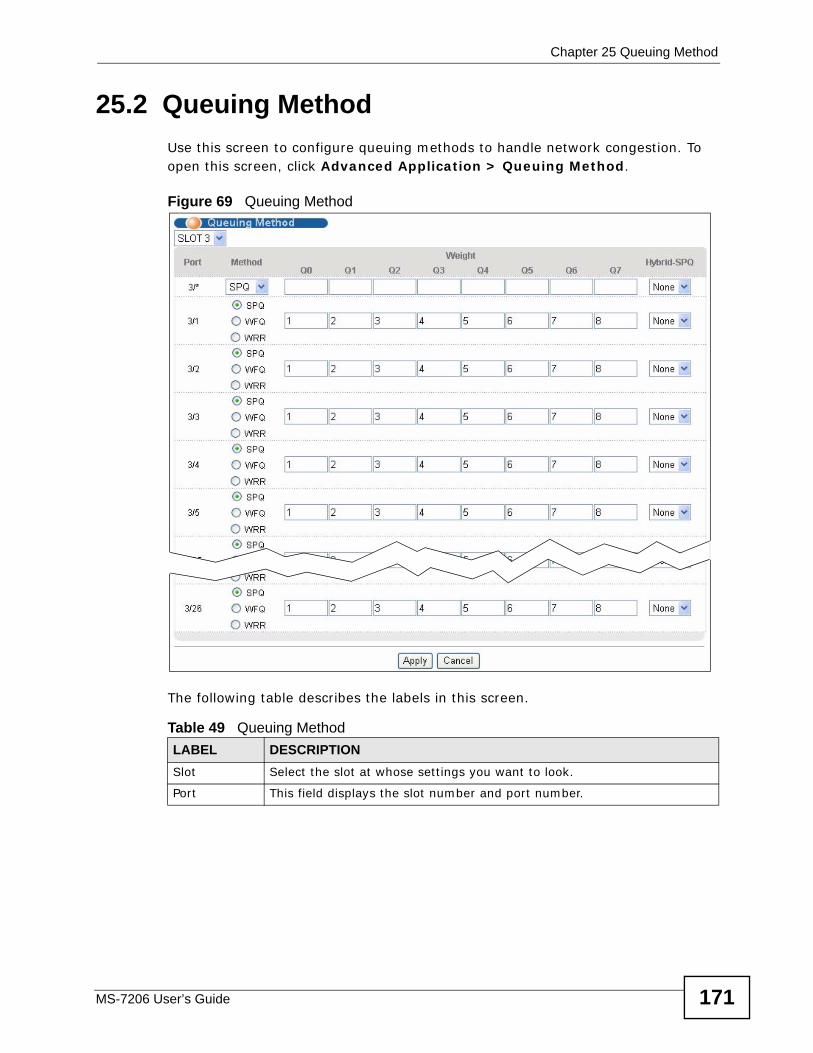
Chapter 25 Queuing Method
MS-7206 User’s Guide 171
25.2 Queuing MethodUse this screen to configure queuing methods to handle network congestion. To open this screen, click Advanced Application > Queuing Method.
Figure 69 Queuing Method
The following table describes the labels in this screen.
Table 49 Queuing Method LABEL DESCRIPTIONSlot Select the slot at whose settings you want to look.
Port This field displays the slot number and port number.
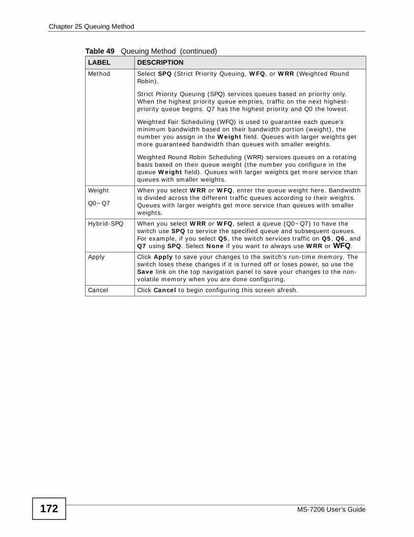
Chapter 25 Queuing Method
MS-7206 User’s Guide172
Method Select SPQ (Strict Priority Queuing, WFQ, or WRR (Weighted Round Robin).
Strict Priority Queuing (SPQ) services queues based on priority only. When the highest priority queue empties, traffic on the next highest-priority queue begins. Q7 has the highest priority and Q0 the lowest.
Weighted Fair Scheduling (WFQ) is used to guarantee each queue’s minimum bandwidth based on their bandwidth portion (weight), the number you assign in the Weight field. Queues with larger weights get more guaranteed bandwidth than queues with smaller weights.
Weighted Round Robin Scheduling (WRR) services queues on a rotating basis based on their queue weight (the number you configure in the queue Weight field). Queues with larger weights get more service than queues with smaller weights.
Weight
Q0~Q7
When you select WRR or WFQ, enter the queue weight here. Bandwidth is divided across the different traffic queues according to their weights. Queues with larger weights get more service than queues with smaller weights.
Hybrid-SPQ When you select WRR or WFQ, select a queue (Q0~Q7) to have the switch use SPQ to service the specified queue and subsequent queues. For example, if you select Q5, the switch services traffic on Q5, Q6, and Q7 using SPQ. Select None if you want to always use WRR or WFQ.
Apply Click Apply to save your changes to the switch’s run-time memory. The switch loses these changes if it is turned off or loses power, so use the Save link on the top navigation panel to save your changes to the non-volatile memory when you are done configuring.
Cancel Click Cancel to begin configuring this screen afresh.
Table 49 Queuing Method (continued)LABEL DESCRIPTION
MS-7206 User’s Guide 173
CHAPTER 26 VLAN Stacking
This chapter shows you how to configure VLAN stacking on your switch. See Chapter 13 on page 85 for background information about VLANs.
26.1 VLAN Stacking OverviewA service provider can use VLAN stacking to allow it to distinguish multiple customers VLANs, even those with the same (customer-assigned) VLAN ID, within its network.
Use VLAN stacking to add an outer VLAN tag to the inner IEEE 802.1Q tagged frames that enter the network. By tagging the tagged frames (“double-tagged” frames), the service provider can manage up to 4,094 VLAN groups with each group containing up to 4,094 customer VLANs. This allows a service provider to provide different service, based on specific VLANs, for many different customers.
A service provider’s customers may require a range of VLANs to handle multiple applications. A service provider’s customers can assign their own inner VLAN tags on ports for these applications. The service provider can assign an outer VLAN tag for each customer. Therefore, there is no VLAN tag overlap among customers, so traffic from different customers is kept separate.
26.1.1 VLAN Stacking ExampleIn the following example figure, both A and B are Service Provider’s Network (SPN) customers with VPN tunnels between their head offices and branch offices respectively. Both have an identical VLAN tag for their VLAN group. The service provider can separate these two VLANs within its network by adding tag 37 to
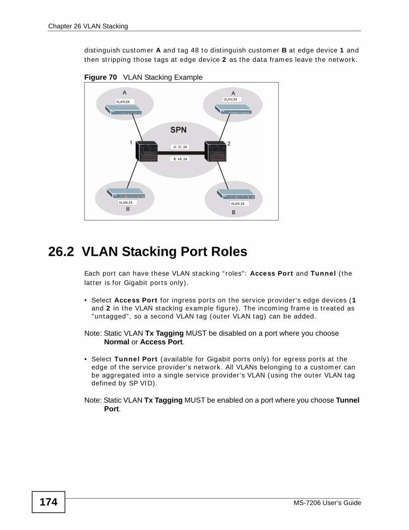
Chapter 26 VLAN Stacking
MS-7206 User’s Guide174
distinguish customer A and tag 48 to distinguish customer B at edge device 1 and then stripping those tags at edge device 2 as the data frames leave the network.
Figure 70 VLAN Stacking Example
26.2 VLAN Stacking Port RolesEach port can have these VLAN stacking “roles”: Access Port and Tunnel (the latter is for Gigabit ports only).
• Select Access Port for ingress ports on the service provider's edge devices (1 and 2 in the VLAN stacking example figure). The incoming frame is treated as "untagged", so a second VLAN tag (outer VLAN tag) can be added.
Note: Static VLAN Tx Tagging MUST be disabled on a port where you choose Normal or Access Port.
• Select Tunnel Port (available for Gigabit ports only) for egress ports at the edge of the service provider's network. All VLANs belonging to a customer can be aggregated into a single service provider's VLAN (using the outer VLAN tag defined by SP VID).
Note: Static VLAN Tx Tagging MUST be enabled on a port where you choose Tunnel Port.
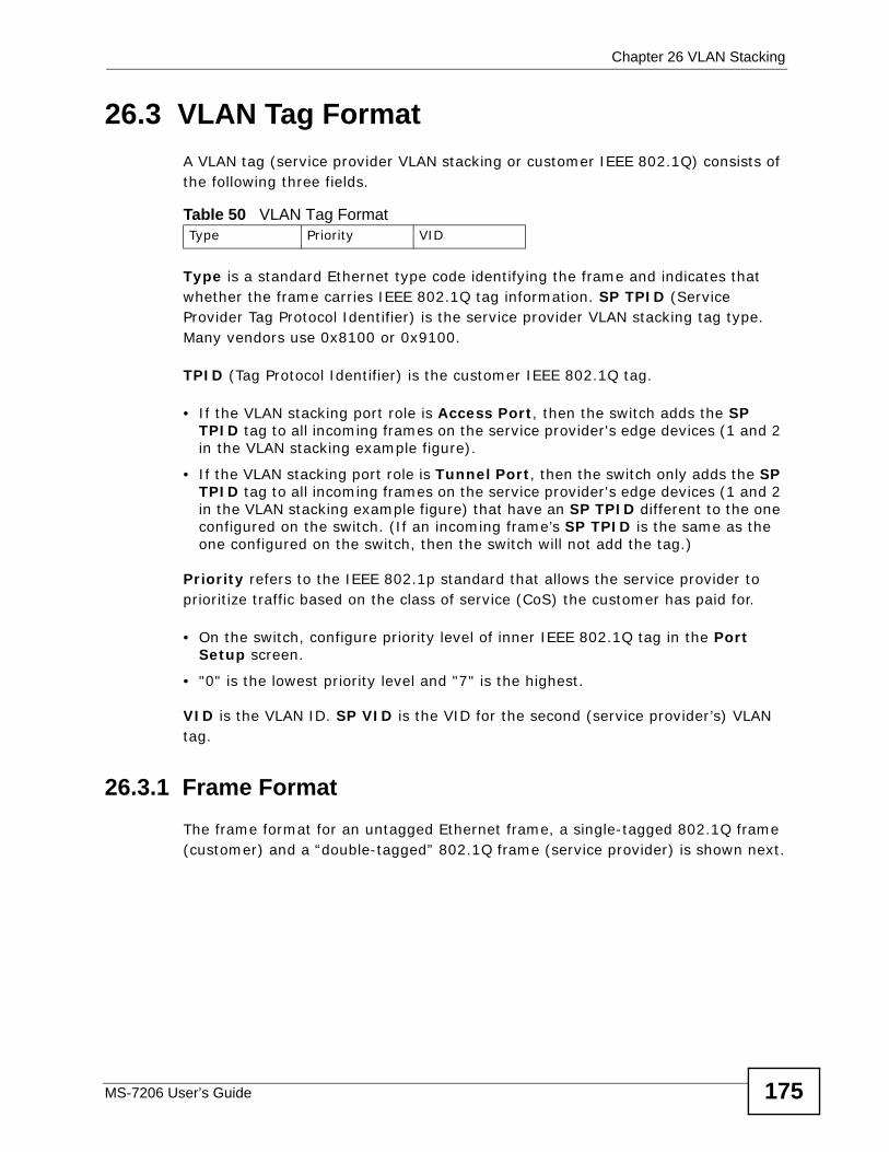
Chapter 26 VLAN Stacking
MS-7206 User’s Guide 175
26.3 VLAN Tag FormatA VLAN tag (service provider VLAN stacking or customer IEEE 802.1Q) consists of the following three fields.
Type is a standard Ethernet type code identifying the frame and indicates that whether the frame carries IEEE 802.1Q tag information. SP TPID (Service Provider Tag Protocol Identifier) is the service provider VLAN stacking tag type. Many vendors use 0x8100 or 0x9100.
TPID (Tag Protocol Identifier) is the customer IEEE 802.1Q tag.
• If the VLAN stacking port role is Access Port, then the switch adds the SP TPID tag to all incoming frames on the service provider's edge devices (1 and 2 in the VLAN stacking example figure).
• If the VLAN stacking port role is Tunnel Port, then the switch only adds the SP TPID tag to all incoming frames on the service provider's edge devices (1 and 2 in the VLAN stacking example figure) that have an SP TPID different to the one configured on the switch. (If an incoming frame’s SP TPID is the same as the one configured on the switch, then the switch will not add the tag.)
Priority refers to the IEEE 802.1p standard that allows the service provider to prioritize traffic based on the class of service (CoS) the customer has paid for.
• On the switch, configure priority level of inner IEEE 802.1Q tag in the Port Setup screen.
• "0" is the lowest priority level and "7" is the highest.
VID is the VLAN ID. SP VID is the VID for the second (service provider’s) VLAN tag.
26.3.1 Frame FormatThe frame format for an untagged Ethernet frame, a single-tagged 802.1Q frame (customer) and a “double-tagged” 802.1Q frame (service provider) is shown next.
Table 50 VLAN Tag FormatType Priority VID
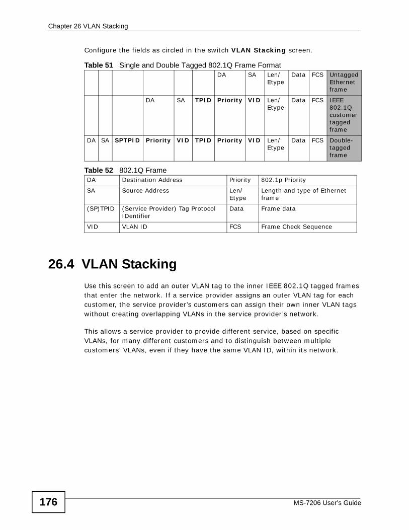
Chapter 26 VLAN Stacking
MS-7206 User’s Guide176
Configure the fields as circled in the switch VLAN Stacking screen.
26.4 VLAN StackingUse this screen to add an outer VLAN tag to the inner IEEE 802.1Q tagged frames that enter the network. If a service provider assigns an outer VLAN tag for each customer, the service provider’s customers can assign their own inner VLAN tags without creating overlapping VLANs in the service provider’s network.
This allows a service provider to provide different service, based on specific VLANs, for many different customers and to distinguish between multiple customers’ VLANs, even if they have the same VLAN ID, within its network.
Table 51 Single and Double Tagged 802.1Q Frame FormatDA SA Len/
EtypeData FCS Untagged
Ethernet frame
DA SA TPID Priority VID Len/Etype
Data FCS IEEE 802.1Q customer tagged frame
DA SA SPTPID Priority VID TPID Priority VID Len/Etype
Data FCS Double-tagged frame
Table 52 802.1Q Frame DA Destination Address Priority 802.1p Priority
SA Source Address Len/Etype
Length and type of Ethernet frame
(SP)TPID (Service Provider) Tag Protocol IDentifier
Data Frame data
VID VLAN ID FCS Frame Check Sequence
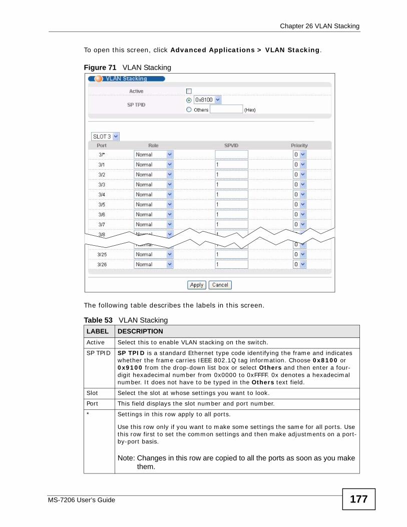
Chapter 26 VLAN Stacking
MS-7206 User’s Guide 177
To open this screen, click Advanced Applications > VLAN Stacking.
Figure 71 VLAN Stacking
The following table describes the labels in this screen.
Table 53 VLAN StackingLABEL DESCRIPTIONActive Select this to enable VLAN stacking on the switch.
SP TPID SP TPID is a standard Ethernet type code identifying the frame and indicates whether the frame carries IEEE 802.1Q tag information. Choose 0x8100 or 0x9100 from the drop-down list box or select Others and then enter a four-digit hexadecimal number from 0x0000 to 0xFFFF. 0x denotes a hexadecimal number. It does not have to be typed in the Others text field.
Slot Select the slot at whose settings you want to look.
Port This field displays the slot number and port number.
* Settings in this row apply to all ports.
Use this row only if you want to make some settings the same for all ports. Use this row first to set the common settings and then make adjustments on a port-by-port basis.
Note: Changes in this row are copied to all the ports as soon as you make them.
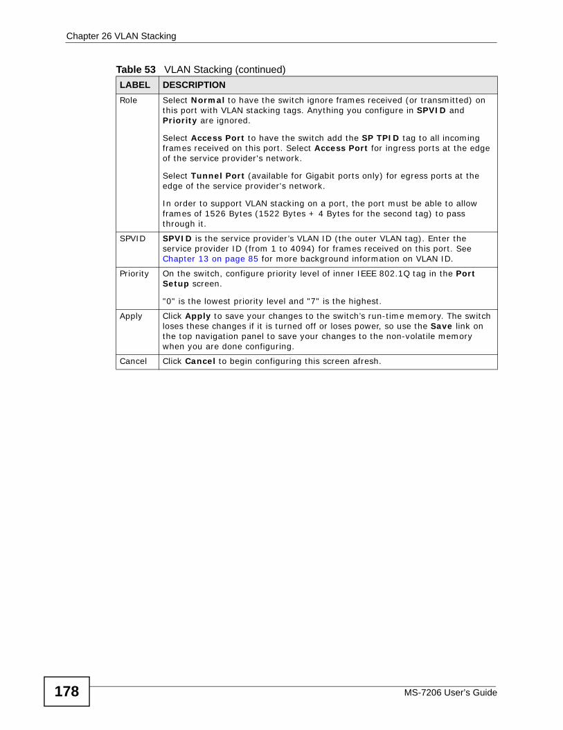
Chapter 26 VLAN Stacking
MS-7206 User’s Guide178
Role Select Normal to have the switch ignore frames received (or transmitted) on this port with VLAN stacking tags. Anything you configure in SPVID and Priority are ignored.
Select Access Port to have the switch add the SP TPID tag to all incoming frames received on this port. Select Access Port for ingress ports at the edge of the service provider's network.
Select Tunnel Port (available for Gigabit ports only) for egress ports at the edge of the service provider's network.
In order to support VLAN stacking on a port, the port must be able to allow frames of 1526 Bytes (1522 Bytes + 4 Bytes for the second tag) to pass through it.
SPVID SPVID is the service provider’s VLAN ID (the outer VLAN tag). Enter the service provider ID (from 1 to 4094) for frames received on this port. See Chapter 13 on page 85 for more background information on VLAN ID.
Priority On the switch, configure priority level of inner IEEE 802.1Q tag in the Port Setup screen.
"0" is the lowest priority level and "7" is the highest.
Apply Click Apply to save your changes to the switch’s run-time memory. The switch loses these changes if it is turned off or loses power, so use the Save link on the top navigation panel to save your changes to the non-volatile memory when you are done configuring.
Cancel Click Cancel to begin configuring this screen afresh.
Table 53 VLAN Stacking (continued)LABEL DESCRIPTION
MS-7206 User’s Guide 179
CHAPTER 27 Multicast
This chapter shows you how to configure various multicast features.
27.1 Multicast Overview Traditionally, IP packets are transmitted in one of either two ways - Unicast (1 sender to 1 recipient) or Broadcast (1 sender to everybody on the network). Multicast delivers IP packets to just a group of hosts on the network.
IGMP (Internet Group Multicast Protocol) is a network-layer protocol used to establish membership in a multicast group - it is not used to carry user data. Refer to RFC 1112 and RFC 2236 for information on IGMP versions 1 and 2 respectively.
27.1.1 IP Multicast AddressesIn IPv4, a multicast address allows a device to send packets to a specific group of hosts (multicast group) in a different subnetwork. A multicast IP address represents a traffic receiving group, not individual receiving devices. IP addresses in the Class D range (224.0.0.0 to 239.255.255.255) are used for IP multicasting. Certain IP multicast numbers are reserved by IANA for special purposes (see the IANA web site for more information).
27.1.2 IGMP FilteringWith the IGMP filtering feature, you can control which IGMP groups a subscriber on a port can join. This allows you to control the distribution of multicast services (such as content information distribution) based on service plans and types of subscription.
You can set the switch to filter the multicast group join reports on a per-port basis by configuring an IGMP filtering profile and associating the profile to a port.
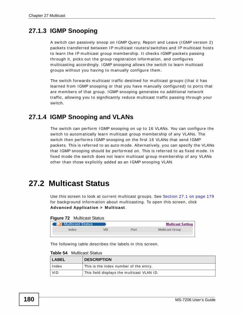
Chapter 27 Multicast
MS-7206 User’s Guide180
27.1.3 IGMP Snooping A switch can passively snoop on IGMP Query, Report and Leave (IGMP version 2) packets transferred between IP multicast routers/switches and IP multicast hosts to learn the IP multicast group membership. It checks IGMP packets passing through it, picks out the group registration information, and configures multicasting accordingly. IGMP snooping allows the switch to learn multicast groups without you having to manually configure them.
The switch forwards multicast traffic destined for multicast groups (that it has learned from IGMP snooping or that you have manually configured) to ports that are members of that group. IGMP snooping generates no additional network traffic, allowing you to significantly reduce multicast traffic passing through your switch.
27.1.4 IGMP Snooping and VLANsThe switch can perform IGMP snooping on up to 16 VLANs. You can configure the switch to automatically learn multicast group membership of any VLANs. The switch then performs IGMP snooping on the first 16 VLANs that send IGMP packets. This is referred to as auto mode. Alternatively, you can specify the VLANs that IGMP snooping should be performed on. This is referred to as fixed mode. In fixed mode the switch does not learn multicast group membership of any VLANs other than those explicitly added as an IGMP snooping VLAN.
27.2 Multicast Status Use this screen to look at current multicast groups. See Section 27.1 on page 179 for background information about multicasting. To open this screen, click Advanced Application > Multicast.
Figure 72 Multicast Status
The following table describes the labels in this screen.
Table 54 Multicast Status LABEL DESCRIPTIONIndex This is the index number of the entry.
VID This field displays the multicast VLAN ID.
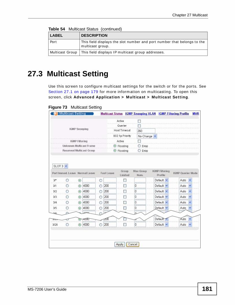
Chapter 27 Multicast
MS-7206 User’s Guide 181
27.3 Multicast Setting Use this screen to configure multicast settings for the switch or for the ports. See Section 27.1 on page 179 for more information on multicasting. To open this screen, click Advanced Application > Multicast > Multicast Setting.
Figure 73 Multicast Setting
Port This field displays the slot number and port number that belongs to the multicast group.
Multicast Group This field displays IP multicast group addresses.
Table 54 Multicast Status (continued)LABEL DESCRIPTION
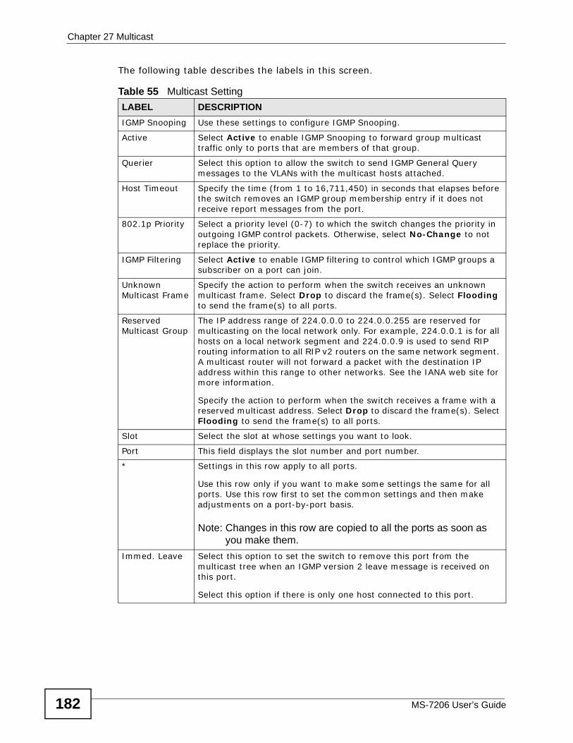
Chapter 27 Multicast
MS-7206 User’s Guide182
The following table describes the labels in this screen.
Table 55 Multicast Setting LABEL DESCRIPTIONIGMP Snooping Use these settings to configure IGMP Snooping.
Active Select Active to enable IGMP Snooping to forward group multicast traffic only to ports that are members of that group.
Querier Select this option to allow the switch to send IGMP General Query messages to the VLANs with the multicast hosts attached.
Host Timeout Specify the time (from 1 to 16,711,450) in seconds that elapses before the switch removes an IGMP group membership entry if it does not receive report messages from the port.
802.1p Priority Select a priority level (0-7) to which the switch changes the priority in outgoing IGMP control packets. Otherwise, select No-Change to not replace the priority.
IGMP Filtering Select Active to enable IGMP filtering to control which IGMP groups a subscriber on a port can join.
Unknown Multicast Frame
Specify the action to perform when the switch receives an unknown multicast frame. Select Drop to discard the frame(s). Select Flooding to send the frame(s) to all ports.
Reserved Multicast Group
The IP address range of 224.0.0.0 to 224.0.0.255 are reserved for multicasting on the local network only. For example, 224.0.0.1 is for all hosts on a local network segment and 224.0.0.9 is used to send RIP routing information to all RIP v2 routers on the same network segment. A multicast router will not forward a packet with the destination IP address within this range to other networks. See the IANA web site for more information.
Specify the action to perform when the switch receives a frame with a reserved multicast address. Select Drop to discard the frame(s). Select Flooding to send the frame(s) to all ports.
Slot Select the slot at whose settings you want to look.
Port This field displays the slot number and port number.
* Settings in this row apply to all ports.
Use this row only if you want to make some settings the same for all ports. Use this row first to set the common settings and then make adjustments on a port-by-port basis.
Note: Changes in this row are copied to all the ports as soon as you make them.
Immed. Leave Select this option to set the switch to remove this port from the multicast tree when an IGMP version 2 leave message is received on this port.
Select this option if there is only one host connected to this port.
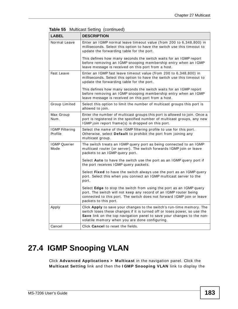
Chapter 27 Multicast
MS-7206 User’s Guide 183
27.4 IGMP Snooping VLAN Click Advanced Applications > Multicast in the navigation panel. Click the Multicast Setting link and then the IGMP Snooping VLAN link to display the
Normal Leave Enter an IGMP normal leave timeout value (from 200 to 6,348,800) in milliseconds. Select this option to have the switch use this timeout to update the forwarding table for the port.
This defines how many seconds the switch waits for an IGMP report before removing an IGMP snooping membership entry when an IGMP leave message is received on this port from a host.
Fast Leave Enter an IGMP fast leave timeout value (from 200 to 6,348,800) in milliseconds. Select this option to have the switch use this timeout to update the forwarding table for the port.
This defines how many seconds the switch waits for an IGMP report before removing an IGMP snooping membership entry when an IGMP leave message is received on this port from a host.
Group Limited Select this option to limit the number of multicast groups this port is allowed to join.
Max Group Num.
Enter the number of multicast groups this port is allowed to join. Once a port is registered in the specified number of multicast groups, any new IGMP join report frame(s) is dropped on this port.
IGMP Filtering Profile
Select the name of the IGMP filtering profile to use for this port. Otherwise, select Default to prohibit the port from joining any multicast group.
IGMP Querier Mode
The switch treats an IGMP query port as being connected to an IGMP multicast router (or server). The switch forwards IGMP join or leave packets to an IGMP query port.
Select Auto to have the switch use the port as an IGMP query port if the port receives IGMP query packets.
Select Fixed to have the switch always use the port as an IGMP query port. Select this when you connect an IGMP multicast server to the port.
Select Edge to stop the switch from using the port as an IGMP query port. The switch will not keep any record of an IGMP router being connected to this port. The switch does not forward IGMP join or leave packets to this port.
Apply Click Apply to save your changes to the switch’s run-time memory. The switch loses these changes if it is turned off or loses power, so use the Save link on the top navigation panel to save your changes to the non-volatile memory when you are done configuring.
Cancel Click Cancel to reset the fields.
Table 55 Multicast Setting (continued)LABEL DESCRIPTION
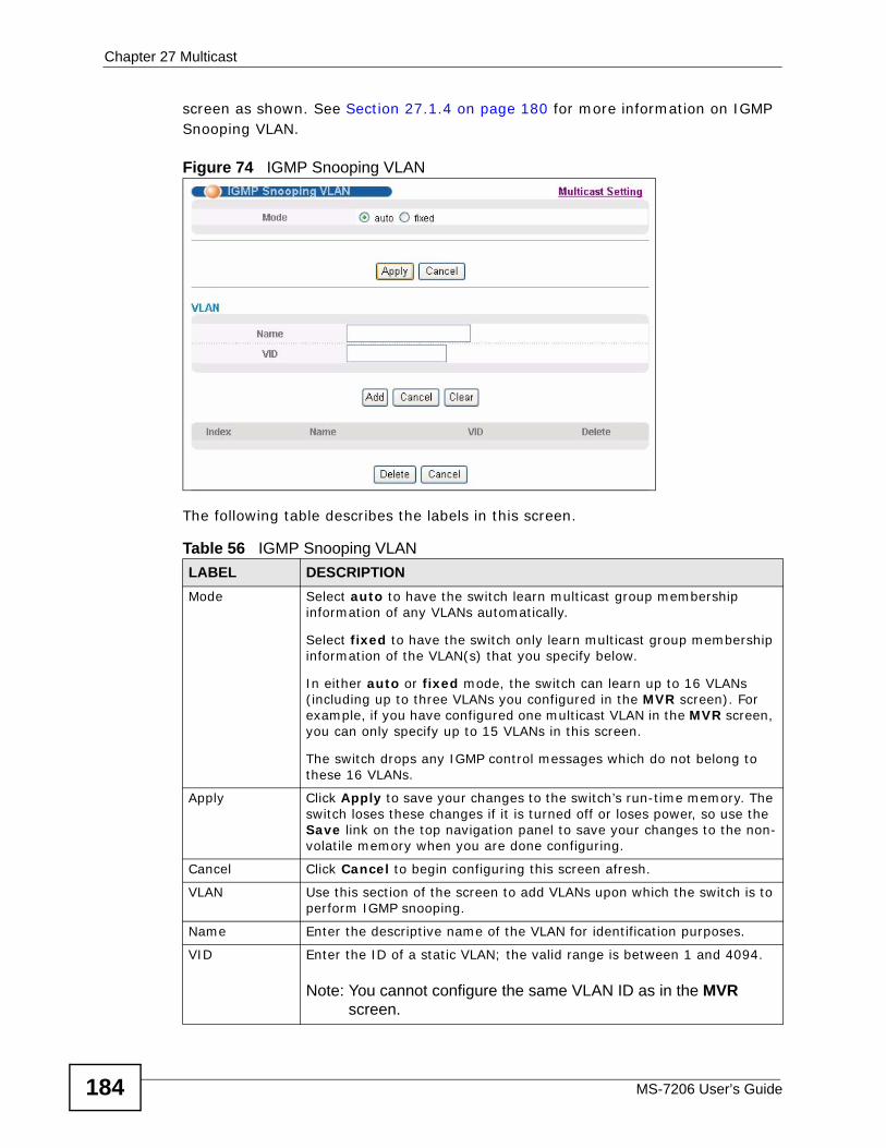
Chapter 27 Multicast
MS-7206 User’s Guide184
screen as shown. See Section 27.1.4 on page 180 for more information on IGMP Snooping VLAN.
Figure 74 IGMP Snooping VLAN
The following table describes the labels in this screen.
Table 56 IGMP Snooping VLANLABEL DESCRIPTIONMode Select auto to have the switch learn multicast group membership
information of any VLANs automatically.
Select fixed to have the switch only learn multicast group membership information of the VLAN(s) that you specify below.
In either auto or fixed mode, the switch can learn up to 16 VLANs (including up to three VLANs you configured in the MVR screen). For example, if you have configured one multicast VLAN in the MVR screen, you can only specify up to 15 VLANs in this screen.
The switch drops any IGMP control messages which do not belong to these 16 VLANs.
Apply Click Apply to save your changes to the switch’s run-time memory. The switch loses these changes if it is turned off or loses power, so use the Save link on the top navigation panel to save your changes to the non-volatile memory when you are done configuring.
Cancel Click Cancel to begin configuring this screen afresh.
VLAN Use this section of the screen to add VLANs upon which the switch is to perform IGMP snooping.
Name Enter the descriptive name of the VLAN for identification purposes.
VID Enter the ID of a static VLAN; the valid range is between 1 and 4094.
Note: You cannot configure the same VLAN ID as in the MVR screen.
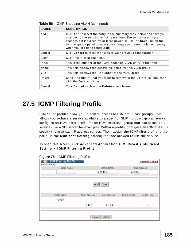
Chapter 27 Multicast
MS-7206 User’s Guide 185
27.5 IGMP Filtering Profile IGMP filter profiles allow you to control access to IGMP multicast groups. This allows you to have a service available to a specific IGMP multicast group. You can configure an IGMP filter profile for an IGMP multicast group that has access to a service (like a SIP server for example). Within a profile, configure an IGMP filter to specify the multicast IP address ranges. Then, assign the IGMP filter profile to the ports (in the Multicast Setting screen) that are allowed to use the service.
To open this screen, click Advanced Application > Multicast > Multicast Setting > IGMP Filtering Profile.
Figure 75 IGMP Filtering Profile
Add Click Add to insert the entry in the summary table below and save your changes to the switch’s run-time memory. The switch loses these changes if it is turned off or loses power, so use the Save link on the top navigation panel to save your changes to the non-volatile memory when you are done configuring.
Cancel Click Cancel to reset the fields to your previous configuration.
Clear Click this to clear the fields.
Index This is the number of the IGMP snooping VLAN entry in the table.
Name This field displays the descriptive name for this VLAN group.
VID This field displays the ID number of the VLAN group.
Delete Check the rule(s) that you want to remove in the Delete column, then click the Delete button.
Cancel Click Cancel to clear the Delete check boxes.
Table 56 IGMP Snooping VLAN (continued)LABEL DESCRIPTION
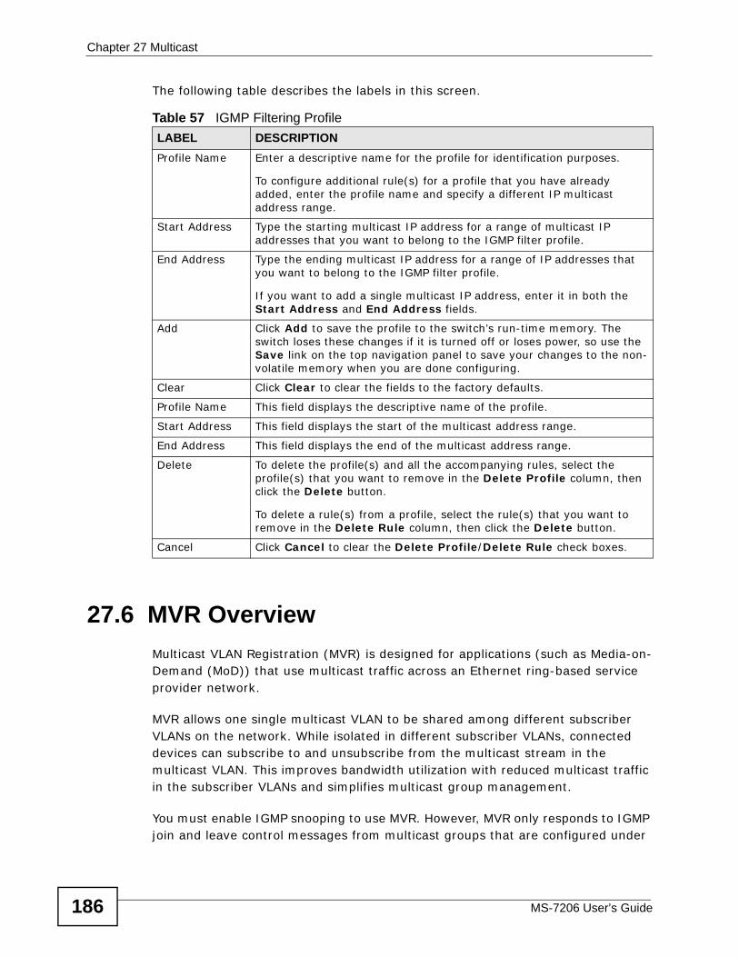
Chapter 27 Multicast
MS-7206 User’s Guide186
The following table describes the labels in this screen.
27.6 MVR OverviewMulticast VLAN Registration (MVR) is designed for applications (such as Media-on-Demand (MoD)) that use multicast traffic across an Ethernet ring-based service provider network.
MVR allows one single multicast VLAN to be shared among different subscriber VLANs on the network. While isolated in different subscriber VLANs, connected devices can subscribe to and unsubscribe from the multicast stream in the multicast VLAN. This improves bandwidth utilization with reduced multicast traffic in the subscriber VLANs and simplifies multicast group management.
You must enable IGMP snooping to use MVR. However, MVR only responds to IGMP join and leave control messages from multicast groups that are configured under
Table 57 IGMP Filtering ProfileLABEL DESCRIPTIONProfile Name Enter a descriptive name for the profile for identification purposes.
To configure additional rule(s) for a profile that you have already added, enter the profile name and specify a different IP multicast address range.
Start Address Type the starting multicast IP address for a range of multicast IP addresses that you want to belong to the IGMP filter profile.
End Address Type the ending multicast IP address for a range of IP addresses that you want to belong to the IGMP filter profile.
If you want to add a single multicast IP address, enter it in both the Start Address and End Address fields.
Add Click Add to save the profile to the switch’s run-time memory. The switch loses these changes if it is turned off or loses power, so use the Save link on the top navigation panel to save your changes to the non-volatile memory when you are done configuring.
Clear Click Clear to clear the fields to the factory defaults.
Profile Name This field displays the descriptive name of the profile.
Start Address This field displays the start of the multicast address range.
End Address This field displays the end of the multicast address range.
Delete To delete the profile(s) and all the accompanying rules, select the profile(s) that you want to remove in the Delete Profile column, then click the Delete button.
To delete a rule(s) from a profile, select the rule(s) that you want to remove in the Delete Rule column, then click the Delete button.
Cancel Click Cancel to clear the Delete Profile/Delete Rule check boxes.
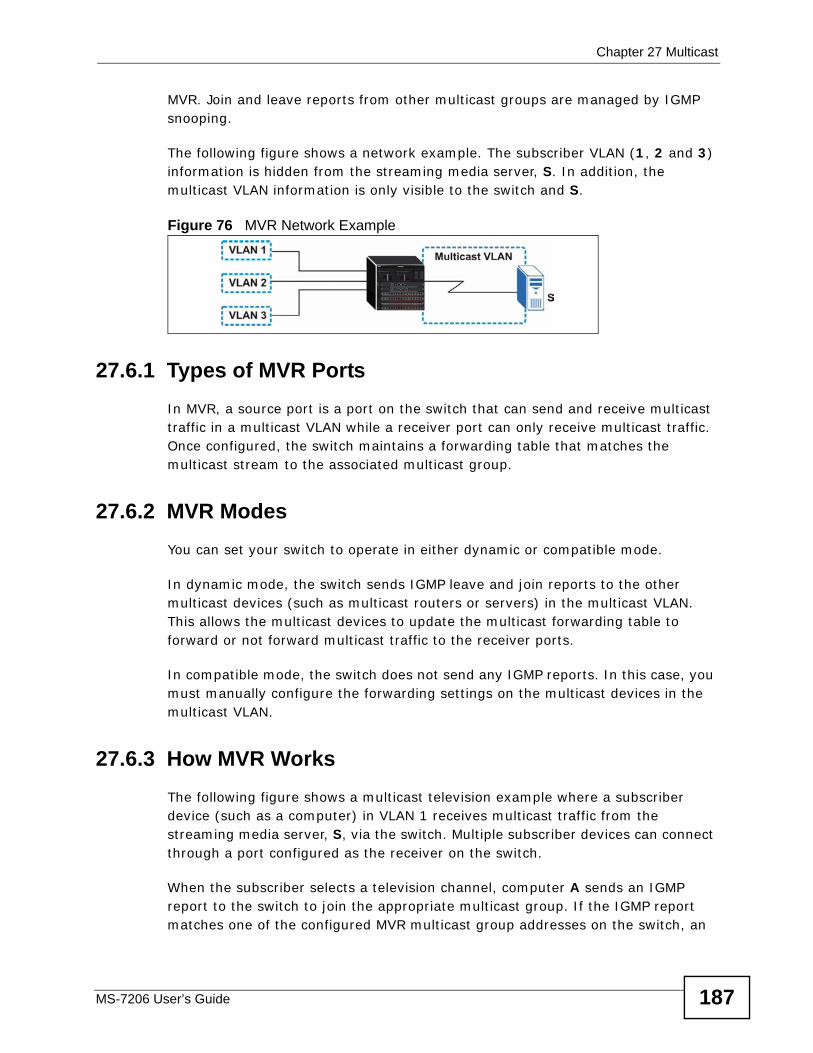
Chapter 27 Multicast
MS-7206 User’s Guide 187
MVR. Join and leave reports from other multicast groups are managed by IGMP snooping.
The following figure shows a network example. The subscriber VLAN (1, 2 and 3) information is hidden from the streaming media server, S. In addition, the multicast VLAN information is only visible to the switch and S.
Figure 76 MVR Network Example
27.6.1 Types of MVR PortsIn MVR, a source port is a port on the switch that can send and receive multicast traffic in a multicast VLAN while a receiver port can only receive multicast traffic. Once configured, the switch maintains a forwarding table that matches the multicast stream to the associated multicast group.
27.6.2 MVR ModesYou can set your switch to operate in either dynamic or compatible mode.
In dynamic mode, the switch sends IGMP leave and join reports to the other multicast devices (such as multicast routers or servers) in the multicast VLAN. This allows the multicast devices to update the multicast forwarding table to forward or not forward multicast traffic to the receiver ports.
In compatible mode, the switch does not send any IGMP reports. In this case, you must manually configure the forwarding settings on the multicast devices in the multicast VLAN.
27.6.3 How MVR WorksThe following figure shows a multicast television example where a subscriber device (such as a computer) in VLAN 1 receives multicast traffic from the streaming media server, S, via the switch. Multiple subscriber devices can connect through a port configured as the receiver on the switch.
When the subscriber selects a television channel, computer A sends an IGMP report to the switch to join the appropriate multicast group. If the IGMP report matches one of the configured MVR multicast group addresses on the switch, an
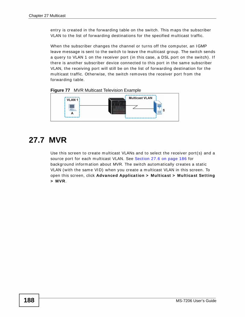
Chapter 27 Multicast
MS-7206 User’s Guide188
entry is created in the forwarding table on the switch. This maps the subscriber VLAN to the list of forwarding destinations for the specified multicast traffic.
When the subscriber changes the channel or turns off the computer, an IGMP leave message is sent to the switch to leave the multicast group. The switch sends a query to VLAN 1 on the receiver port (in this case, a DSL port on the switch). If there is another subscriber device connected to this port in the same subscriber VLAN, the receiving port will still be on the list of forwarding destination for the multicast traffic. Otherwise, the switch removes the receiver port from the forwarding table.
Figure 77 MVR Multicast Television Example
27.7 MVRUse this screen to create multicast VLANs and to select the receiver port(s) and a source port for each multicast VLAN. See Section 27.6 on page 186 for background information about MVR. The switch automatically creates a static VLAN (with the same VID) when you create a multicast VLAN in this screen. To open this screen, click Advanced Application > Multicast > Multicast Setting > MVR.
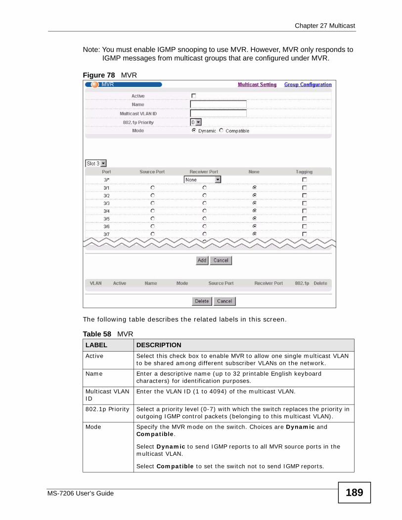
Chapter 27 Multicast
MS-7206 User’s Guide 189
Note: You must enable IGMP snooping to use MVR. However, MVR only responds to IGMP messages from multicast groups that are configured under MVR.
Figure 78 MVR
The following table describes the related labels in this screen.
Table 58 MVRLABEL DESCRIPTIONActive Select this check box to enable MVR to allow one single multicast VLAN
to be shared among different subscriber VLANs on the network.
Name Enter a descriptive name (up to 32 printable English keyboard characters) for identification purposes.
Multicast VLAN ID
Enter the VLAN ID (1 to 4094) of the multicast VLAN.
802.1p Priority Select a priority level (0-7) with which the switch replaces the priority in outgoing IGMP control packets (belonging to this multicast VLAN).
Mode Specify the MVR mode on the switch. Choices are Dynamic and Compatible.
Select Dynamic to send IGMP reports to all MVR source ports in the multicast VLAN.
Select Compatible to set the switch not to send IGMP reports.
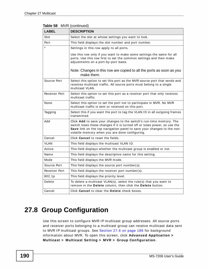
Chapter 27 Multicast
MS-7206 User’s Guide190
27.8 Group Configuration Use this screen to configure MVR IP multicast group addresses. All source ports and receiver ports belonging to a multicast group can receive multicast data sent to MVR IP multicast groups. See Section 27.6 on page 186 for background information about MVR. To open this screen, click Advanced Application > Multicast > Multicast Setting > MVR > Group Configuration.
Slot Select the slot at whose settings you want to look.
Port This field displays the slot number and port number.
* Settings in this row apply to all ports.
Use this row only if you want to make some settings the same for all ports. Use this row first to set the common settings and then make adjustments on a port-by-port basis.
Note: Changes in this row are copied to all the ports as soon as you make them.
Source Port Select this option to set this port as the MVR source port that sends and receives multicast traffic. All source ports must belong to a single multicast VLAN.
Receiver Port Select this option to set this port as a receiver port that only receives multicast traffic.
None Select this option to set the port not to participate in MVR. No MVR multicast traffic is sent or received on this port.
Tagging Select this if you want the port to tag the VLAN ID in all outgoing frames transmitted.
Add Click Add to save your changes to the switch’s run-time memory. The switch loses these changes if it is turned off or loses power, so use the Save link on the top navigation panel to save your changes to the non-volatile memory when you are done configuring.
Cancel Click Cancel to reset the fields.
VLAN This field displays the multicast VLAN ID.
Active This field displays whether the multicast group is enabled or not.
Name This field displays the descriptive name for this setting.
Mode This field displays the MVR mode.
Source Port This field displays the source port number(s).
Receiver Port This field displays the receiver port number(s).
802.1p This field displays the priority level.
Delete To delete a multicast VLAN(s), select the rule(s) that you want to remove in the Delete column, then click the Delete button.
Cancel Click Cancel to clear the Delete check boxes.
Table 58 MVR (continued)LABEL DESCRIPTION
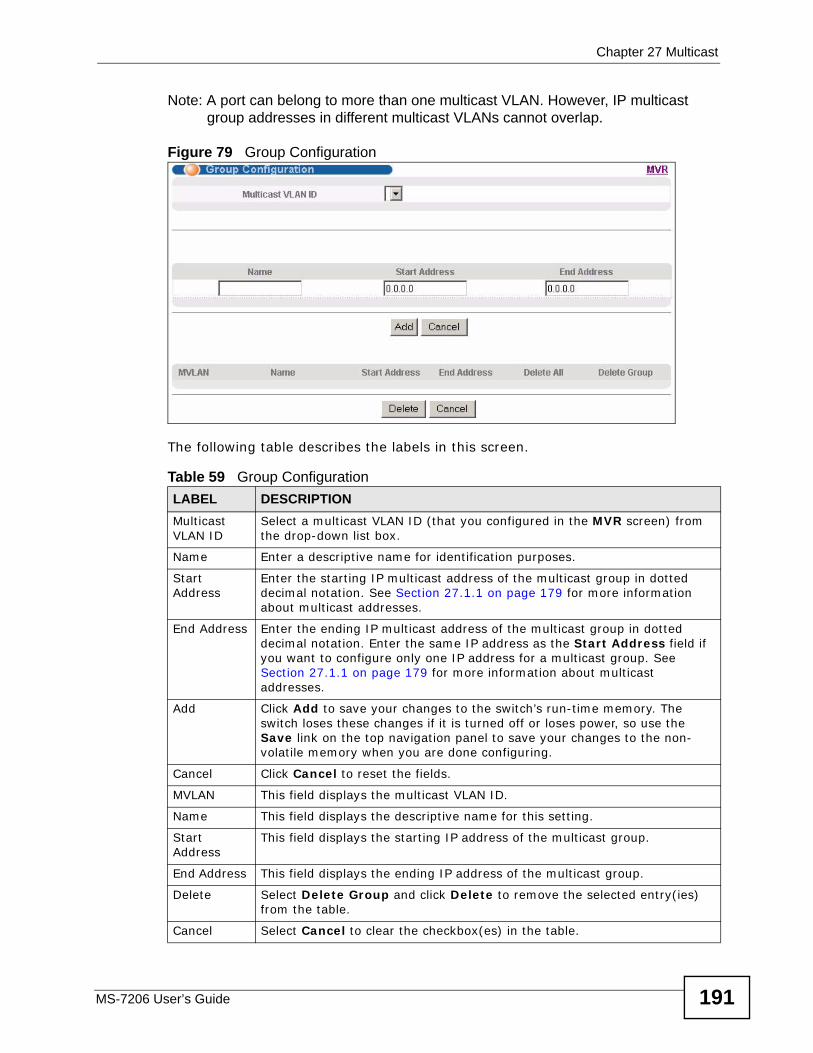
Chapter 27 Multicast
MS-7206 User’s Guide 191
Note: A port can belong to more than one multicast VLAN. However, IP multicast group addresses in different multicast VLANs cannot overlap.
Figure 79 Group Configuration
The following table describes the labels in this screen.
Table 59 Group ConfigurationLABEL DESCRIPTIONMulticast VLAN ID
Select a multicast VLAN ID (that you configured in the MVR screen) from the drop-down list box.
Name Enter a descriptive name for identification purposes.
Start Address
Enter the starting IP multicast address of the multicast group in dotted decimal notation. See Section 27.1.1 on page 179 for more information about multicast addresses.
End Address Enter the ending IP multicast address of the multicast group in dotted decimal notation. Enter the same IP address as the Start Address field if you want to configure only one IP address for a multicast group. See Section 27.1.1 on page 179 for more information about multicast addresses.
Add Click Add to save your changes to the switch’s run-time memory. The switch loses these changes if it is turned off or loses power, so use the Save link on the top navigation panel to save your changes to the non-volatile memory when you are done configuring.
Cancel Click Cancel to reset the fields.
MVLAN This field displays the multicast VLAN ID.
Name This field displays the descriptive name for this setting.
Start Address
This field displays the starting IP address of the multicast group.
End Address This field displays the ending IP address of the multicast group.
Delete Select Delete Group and click Delete to remove the selected entry(ies) from the table.
Cancel Select Cancel to clear the checkbox(es) in the table.
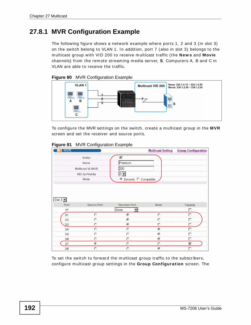
Chapter 27 Multicast
MS-7206 User’s Guide192
27.8.1 MVR Configuration ExampleThe following figure shows a network example where ports 1, 2 and 3 (in slot 3) on the switch belong to VLAN 1. In addition, port 7 (also in slot 3) belongs to the multicast group with VID 200 to receive multicast traffic (the News and Movie channels) from the remote streaming media server, S. Computers A, B and C in VLAN are able to receive the traffic.
Figure 80 MVR Configuration Example
To configure the MVR settings on the switch, create a multicast group in the MVR screen and set the receiver and source ports.
Figure 81 MVR Configuration Example
To set the switch to forward the multicast group traffic to the subscribers, configure multicast group settings in the Group Configuration screen. The
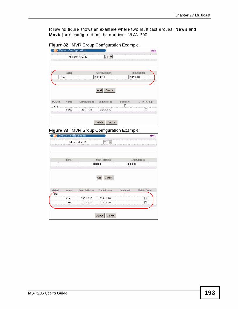
Chapter 27 Multicast
MS-7206 User’s Guide 193
following figure shows an example where two multicast groups (News and Movie) are configured for the multicast VLAN 200.
Figure 82 MVR Group Configuration Example
Figure 83 MVR Group Configuration Example

Chapter 27 Multicast
MS-7206 User’s Guide194
MS-7206 User’s Guide 195
CHAPTER 28 AAA
This chapter describes how to configure authentication, authorization and accounting settings on the switch.
28.1 Authentication, Authorization and Accounting (AAA)
Authentication is the process of determining who a user is and validating access to the switch. The switch can authenticate users who try to log in based on user accounts configured on the switch itself. The switch can also use an external authentication server to authenticate a large number of users
Authorization is the process of determining what a user is allowed to do. Different user accounts may have higher or lower privilege levels associated with them. For example, user A may have the right to create new login accounts on the switch but user B cannot. The switch can authorize users based on user accounts configured on the switch itself or it can use an external server to authorize a large number of users.
Accounting is the process of recording what a user is doing. The switch can use an external server to track when users log in, log out, execute commands and so on. Accounting can also record system related actions such as boot up and shut down times of the switch.
The external servers that perform authentication, authorization and accounting functions are known as AAA servers. The switch supports RADIUS (Remote Authentication Dial-In User Service, see Section 28.1.2 on page 196) and TACACS+ (Terminal Access Controller Access-Control System Plus, see Section
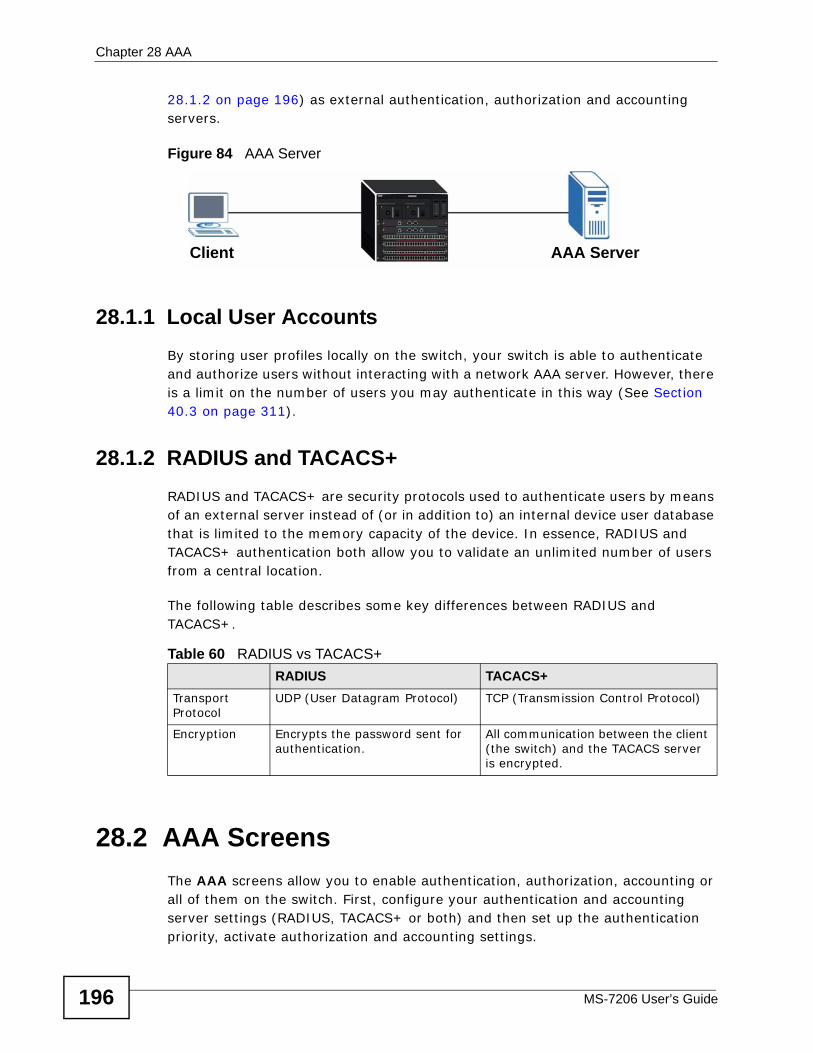
Chapter 28 AAA
MS-7206 User’s Guide196
28.1.2 on page 196) as external authentication, authorization and accounting servers.
Figure 84 AAA Server
28.1.1 Local User AccountsBy storing user profiles locally on the switch, your switch is able to authenticate and authorize users without interacting with a network AAA server. However, there is a limit on the number of users you may authenticate in this way (See Section 40.3 on page 311).
28.1.2 RADIUS and TACACS+ RADIUS and TACACS+ are security protocols used to authenticate users by means of an external server instead of (or in addition to) an internal device user database that is limited to the memory capacity of the device. In essence, RADIUS and TACACS+ authentication both allow you to validate an unlimited number of users from a central location.
The following table describes some key differences between RADIUS and TACACS+.
28.2 AAA Screens The AAA screens allow you to enable authentication, authorization, accounting or all of them on the switch. First, configure your authentication and accounting server settings (RADIUS, TACACS+ or both) and then set up the authentication priority, activate authorization and accounting settings.
Client AAA Server
Table 60 RADIUS vs TACACS+ RADIUS TACACS+
Transport Protocol
UDP (User Datagram Protocol) TCP (Transmission Control Protocol)
Encryption Encrypts the password sent for authentication.
All communication between the client (the switch) and the TACACS server is encrypted.
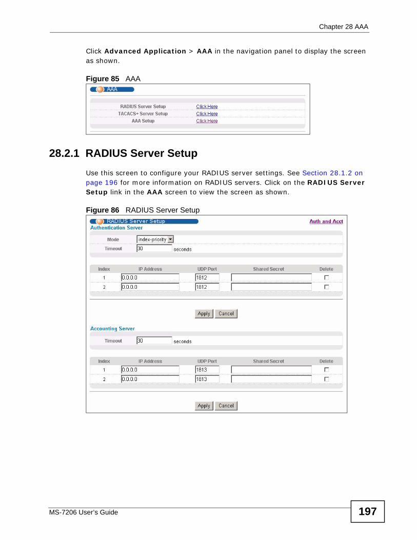
Chapter 28 AAA
MS-7206 User’s Guide 197
Click Advanced Application > AAA in the navigation panel to display the screen as shown.
Figure 85 AAA
28.2.1 RADIUS Server Setup Use this screen to configure your RADIUS server settings. See Section 28.1.2 on page 196 for more information on RADIUS servers. Click on the RADIUS Server Setup link in the AAA screen to view the screen as shown.
Figure 86 RADIUS Server Setup
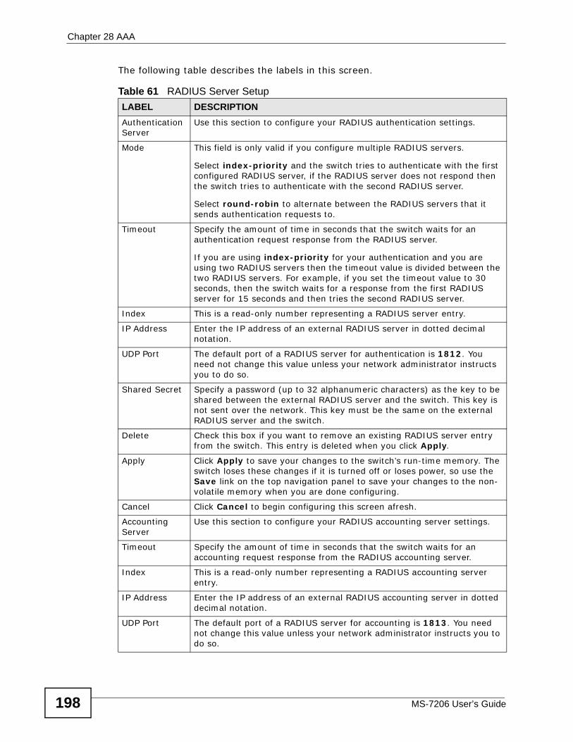
Chapter 28 AAA
MS-7206 User’s Guide198
The following table describes the labels in this screen.
Table 61 RADIUS Server Setup LABEL DESCRIPTIONAuthentication Server
Use this section to configure your RADIUS authentication settings.
Mode This field is only valid if you configure multiple RADIUS servers.
Select index-priority and the switch tries to authenticate with the first configured RADIUS server, if the RADIUS server does not respond then the switch tries to authenticate with the second RADIUS server.
Select round-robin to alternate between the RADIUS servers that it sends authentication requests to.
Timeout Specify the amount of time in seconds that the switch waits for an authentication request response from the RADIUS server.
If you are using index-priority for your authentication and you are using two RADIUS servers then the timeout value is divided between the two RADIUS servers. For example, if you set the timeout value to 30 seconds, then the switch waits for a response from the first RADIUS server for 15 seconds and then tries the second RADIUS server.
Index This is a read-only number representing a RADIUS server entry.
IP Address Enter the IP address of an external RADIUS server in dotted decimal notation.
UDP Port The default port of a RADIUS server for authentication is 1812. You need not change this value unless your network administrator instructs you to do so.
Shared Secret Specify a password (up to 32 alphanumeric characters) as the key to be shared between the external RADIUS server and the switch. This key is not sent over the network. This key must be the same on the external RADIUS server and the switch.
Delete Check this box if you want to remove an existing RADIUS server entry from the switch. This entry is deleted when you click Apply.
Apply Click Apply to save your changes to the switch’s run-time memory. The switch loses these changes if it is turned off or loses power, so use the Save link on the top navigation panel to save your changes to the non-volatile memory when you are done configuring.
Cancel Click Cancel to begin configuring this screen afresh.
Accounting Server
Use this section to configure your RADIUS accounting server settings.
Timeout Specify the amount of time in seconds that the switch waits for an accounting request response from the RADIUS accounting server.
Index This is a read-only number representing a RADIUS accounting server entry.
IP Address Enter the IP address of an external RADIUS accounting server in dotted decimal notation.
UDP Port The default port of a RADIUS server for accounting is 1813. You need not change this value unless your network administrator instructs you to do so.
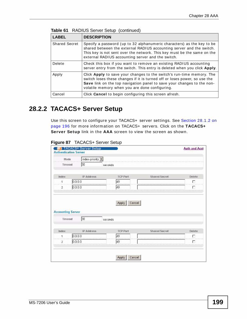
Chapter 28 AAA
MS-7206 User’s Guide 199
28.2.2 TACACS+ Server Setup Use this screen to configure your TACACS+ server settings. See Section 28.1.2 on page 196 for more information on TACACS+ servers. Click on the TACACS+ Server Setup link in the AAA screen to view the screen as shown.
Figure 87 TACACS+ Server Setup
Shared Secret Specify a password (up to 32 alphanumeric characters) as the key to be shared between the external RADIUS accounting server and the switch. This key is not sent over the network. This key must be the same on the external RADIUS accounting server and the switch.
Delete Check this box if you want to remove an existing RADIUS accounting server entry from the switch. This entry is deleted when you click Apply.
Apply Click Apply to save your changes to the switch’s run-time memory. The switch loses these changes if it is turned off or loses power, so use the Save link on the top navigation panel to save your changes to the non-volatile memory when you are done configuring.
Cancel Click Cancel to begin configuring this screen afresh.
Table 61 RADIUS Server Setup (continued)LABEL DESCRIPTION
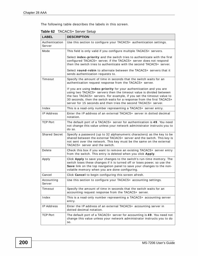
Chapter 28 AAA
MS-7206 User’s Guide200
The following table describes the labels in this screen.
Table 62 TACACS+ Server Setup LABEL DESCRIPTIONAuthentication Server
Use this section to configure your TACACS+ authentication settings.
Mode This field is only valid if you configure multiple TACACS+ servers.
Select index-priority and the switch tries to authenticate with the first configured TACACS+ server, if the TACACS+ server does not respond then the switch tries to authenticate with the second TACACS+ server.
Select round-robin to alternate between the TACACS+ servers that it sends authentication requests to.
Timeout Specify the amount of time in seconds that the switch waits for an authentication request response from the TACACS+ server.
If you are using index-priority for your authentication and you are using two TACACS+ servers then the timeout value is divided between the two TACACS+ servers. For example, if you set the timeout value to 30 seconds, then the switch waits for a response from the first TACACS+ server for 15 seconds and then tries the second TACACS+ server.
Index This is a read-only number representing a TACACS+ server entry.
IP Address Enter the IP address of an external TACACS+ server in dotted decimal notation.
TCP Port The default port of a TACACS+ server for authentication is 49. You need not change this value unless your network administrator instructs you to do so.
Shared Secret Specify a password (up to 32 alphanumeric characters) as the key to be shared between the external TACACS+ server and the switch. This key is not sent over the network. This key must be the same on the external TACACS+ server and the switch.
Delete Check this box if you want to remove an existing TACACS+ server entry from the switch. This entry is deleted when you click Apply.
Apply Click Apply to save your changes to the switch’s run-time memory. The switch loses these changes if it is turned off or loses power, so use the Save link on the top navigation panel to save your changes to the non-volatile memory when you are done configuring.
Cancel Click Cancel to begin configuring this screen afresh.
Accounting Server
Use this section to configure your TACACS+ accounting settings.
Timeout Specify the amount of time in seconds that the switch waits for an accounting request response from the TACACS+ server.
Index This is a read-only number representing a TACACS+ accounting server entry.
IP Address Enter the IP address of an external TACACS+ accounting server in dotted decimal notation.
TCP Port The default port of a TACACS+ server for accounting is 49. You need not change this value unless your network administrator instructs you to do so.
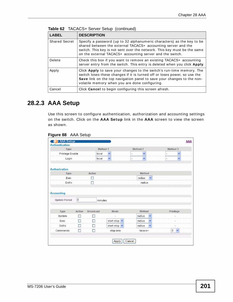
Chapter 28 AAA
MS-7206 User’s Guide 201
28.2.3 AAA Setup Use this screen to configure authentication, authorization and accounting settings on the switch. Click on the AAA Setup link in the AAA screen to view the screen as shown.
Figure 88 AAA Setup
Shared Secret Specify a password (up to 32 alphanumeric characters) as the key to be shared between the external TACACS+ accounting server and the switch. This key is not sent over the network. This key must be the same on the external TACACS+ accounting server and the switch.
Delete Check this box if you want to remove an existing TACACS+ accounting server entry from the switch. This entry is deleted when you click Apply.
Apply Click Apply to save your changes to the switch’s run-time memory. The switch loses these changes if it is turned off or loses power, so use the Save link on the top navigation panel to save your changes to the non-volatile memory when you are done configuring.
Cancel Click Cancel to begin configuring this screen afresh.
Table 62 TACACS+ Server Setup (continued)LABEL DESCRIPTION
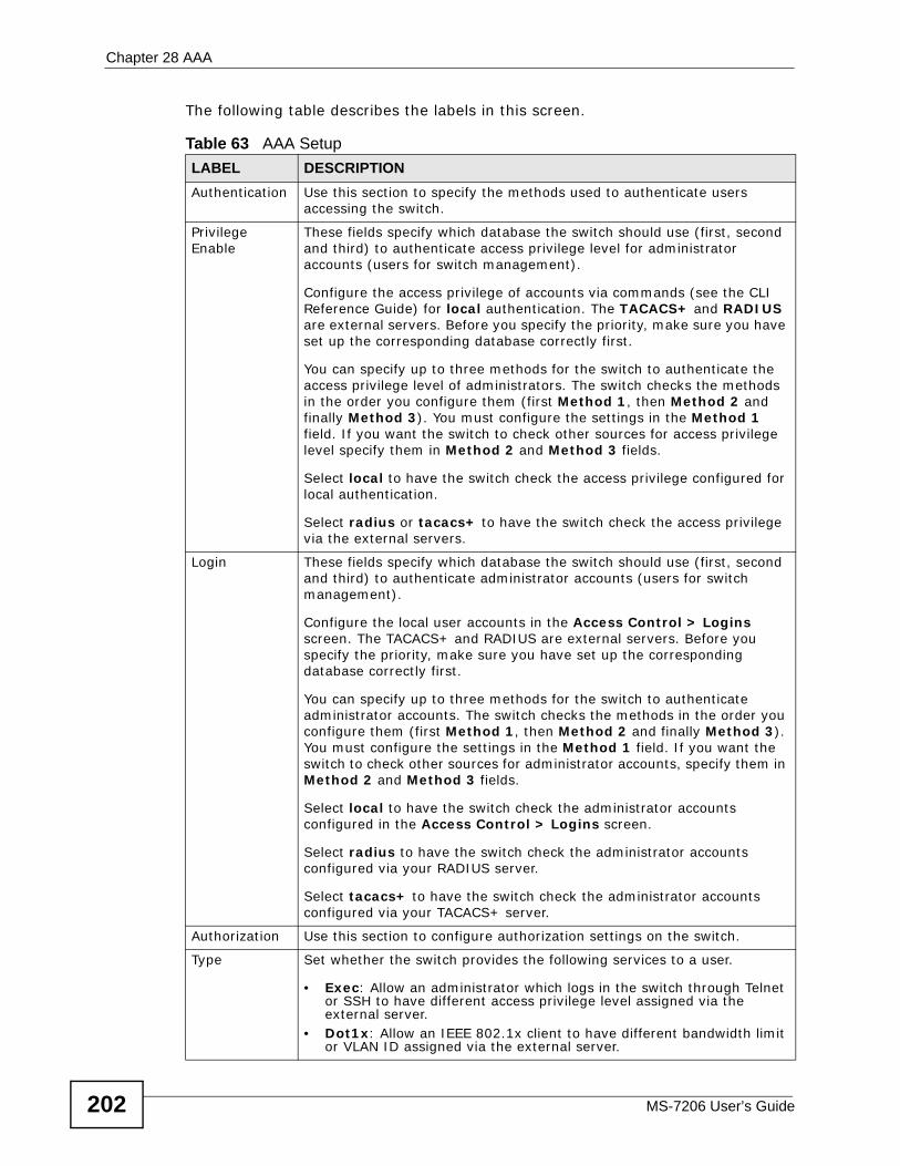
Chapter 28 AAA
MS-7206 User’s Guide202
The following table describes the labels in this screen.
Table 63 AAA Setup LABEL DESCRIPTIONAuthentication Use this section to specify the methods used to authenticate users
accessing the switch.
Privilege Enable
These fields specify which database the switch should use (first, second and third) to authenticate access privilege level for administrator accounts (users for switch management).
Configure the access privilege of accounts via commands (see the CLI Reference Guide) for local authentication. The TACACS+ and RADIUS are external servers. Before you specify the priority, make sure you have set up the corresponding database correctly first.
You can specify up to three methods for the switch to authenticate the access privilege level of administrators. The switch checks the methods in the order you configure them (first Method 1, then Method 2 and finally Method 3). You must configure the settings in the Method 1 field. If you want the switch to check other sources for access privilege level specify them in Method 2 and Method 3 fields.
Select local to have the switch check the access privilege configured for local authentication.
Select radius or tacacs+ to have the switch check the access privilege via the external servers.
Login These fields specify which database the switch should use (first, second and third) to authenticate administrator accounts (users for switch management).
Configure the local user accounts in the Access Control > Logins screen. The TACACS+ and RADIUS are external servers. Before you specify the priority, make sure you have set up the corresponding database correctly first.
You can specify up to three methods for the switch to authenticate administrator accounts. The switch checks the methods in the order you configure them (first Method 1, then Method 2 and finally Method 3). You must configure the settings in the Method 1 field. If you want the switch to check other sources for administrator accounts, specify them in Method 2 and Method 3 fields.
Select local to have the switch check the administrator accounts configured in the Access Control > Logins screen.
Select radius to have the switch check the administrator accounts configured via your RADIUS server.
Select tacacs+ to have the switch check the administrator accounts configured via your TACACS+ server.
Authorization Use this section to configure authorization settings on the switch.
Type Set whether the switch provides the following services to a user.
• Exec: Allow an administrator which logs in the switch through Telnet or SSH to have different access privilege level assigned via the external server.
• Dot1x: Allow an IEEE 802.1x client to have different bandwidth limit or VLAN ID assigned via the external server.
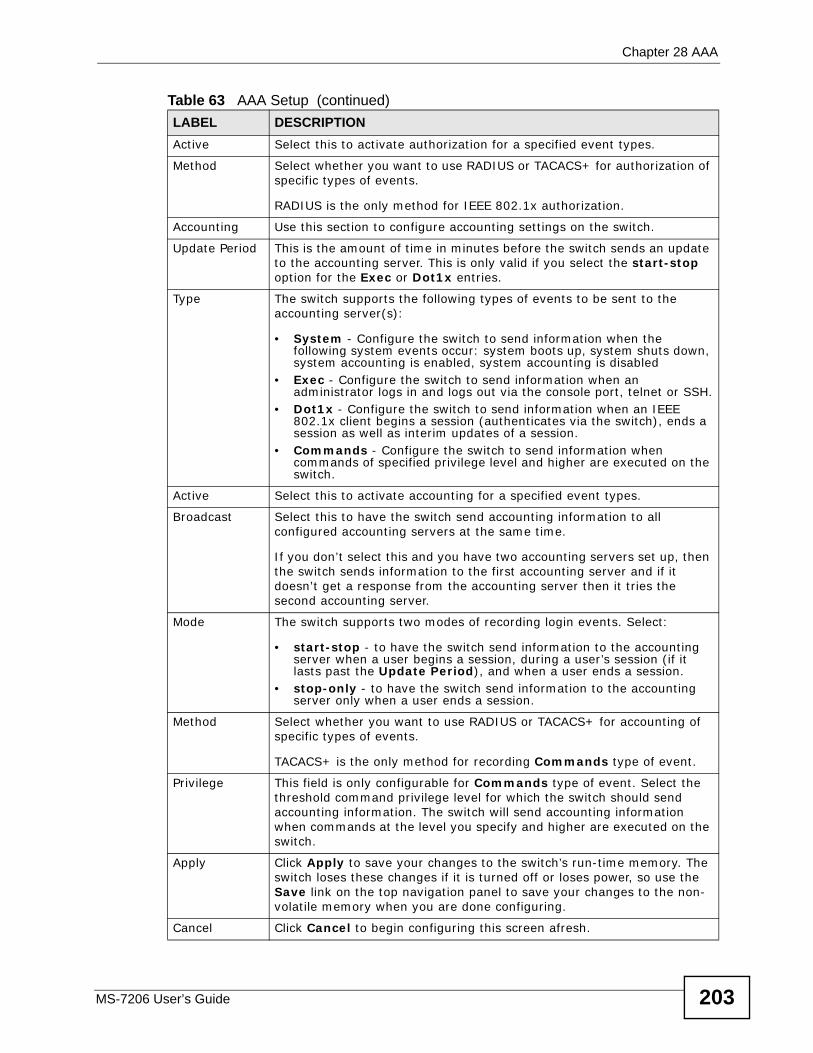
Chapter 28 AAA
MS-7206 User’s Guide 203
Active Select this to activate authorization for a specified event types.
Method Select whether you want to use RADIUS or TACACS+ for authorization of specific types of events.
RADIUS is the only method for IEEE 802.1x authorization.
Accounting Use this section to configure accounting settings on the switch.
Update Period This is the amount of time in minutes before the switch sends an update to the accounting server. This is only valid if you select the start-stop option for the Exec or Dot1x entries.
Type The switch supports the following types of events to be sent to the accounting server(s):
• System - Configure the switch to send information when the following system events occur: system boots up, system shuts down, system accounting is enabled, system accounting is disabled
• Exec - Configure the switch to send information when an administrator logs in and logs out via the console port, telnet or SSH.
• Dot1x - Configure the switch to send information when an IEEE 802.1x client begins a session (authenticates via the switch), ends a session as well as interim updates of a session.
• Commands - Configure the switch to send information when commands of specified privilege level and higher are executed on the switch.
Active Select this to activate accounting for a specified event types.
Broadcast Select this to have the switch send accounting information to all configured accounting servers at the same time.
If you don’t select this and you have two accounting servers set up, then the switch sends information to the first accounting server and if it doesn’t get a response from the accounting server then it tries the second accounting server.
Mode The switch supports two modes of recording login events. Select:
• start-stop - to have the switch send information to the accounting server when a user begins a session, during a user’s session (if it lasts past the Update Period), and when a user ends a session.
• stop-only - to have the switch send information to the accounting server only when a user ends a session.
Method Select whether you want to use RADIUS or TACACS+ for accounting of specific types of events.
TACACS+ is the only method for recording Commands type of event.
Privilege This field is only configurable for Commands type of event. Select the threshold command privilege level for which the switch should send accounting information. The switch will send accounting information when commands at the level you specify and higher are executed on the switch.
Apply Click Apply to save your changes to the switch’s run-time memory. The switch loses these changes if it is turned off or loses power, so use the Save link on the top navigation panel to save your changes to the non-volatile memory when you are done configuring.
Cancel Click Cancel to begin configuring this screen afresh.
Table 63 AAA Setup (continued)LABEL DESCRIPTION
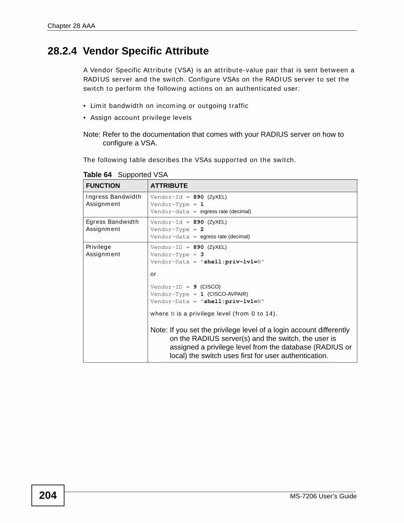
Chapter 28 AAA
MS-7206 User’s Guide204
28.2.4 Vendor Specific AttributeA Vendor Specific Attribute (VSA) is an attribute-value pair that is sent between a RADIUS server and the switch. Configure VSAs on the RADIUS server to set the switch to perform the following actions on an authenticated user:
• Limit bandwidth on incoming or outgoing traffic
• Assign account privilege levels
Note: Refer to the documentation that comes with your RADIUS server on how to configure a VSA.
The following table describes the VSAs supported on the switch.
Table 64 Supported VSA FUNCTION ATTRIBUTEIngress Bandwidth Assignment
Vendor-Id = 890 (ZyXEL)Vendor-Type = 1 Vendor-data = ingress rate (decimal)
Egress Bandwidth Assignment
Vendor-Id = 890 (ZyXEL)Vendor-Type = 2 Vendor-data = egress rate (decimal)
Privilege Assignment
Vendor-ID = 890 (ZyXEL)Vendor-Type = 3 Vendor-Data = "shell:priv-lvl=N" or
Vendor-ID = 9 (CISCO)Vendor-Type = 1 (CISCO-AVPAIR)Vendor-Data = "shell:priv-lvl=N" where N is a privilege level (from 0 to 14).
Note: If you set the privilege level of a login account differently on the RADIUS server(s) and the switch, the user is assigned a privilege level from the database (RADIUS or local) the switch uses first for user authentication.
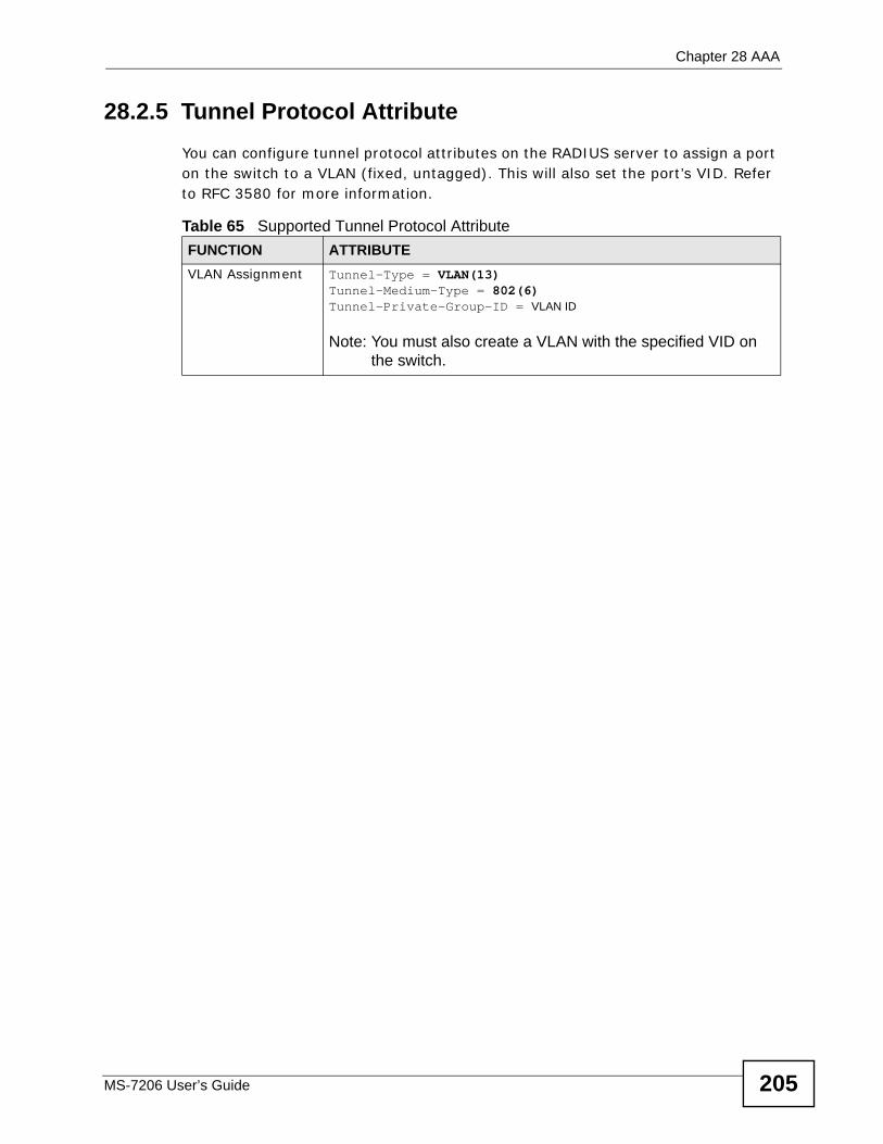
Chapter 28 AAA
MS-7206 User’s Guide 205
28.2.5 Tunnel Protocol Attribute You can configure tunnel protocol attributes on the RADIUS server to assign a port on the switch to a VLAN (fixed, untagged). This will also set the port’s VID. Refer to RFC 3580 for more information.
Table 65 Supported Tunnel Protocol AttributeFUNCTION ATTRIBUTEVLAN Assignment Tunnel-Type = VLAN(13)
Tunnel-Medium-Type = 802(6)Tunnel-Private-Group-ID = VLAN ID
Note: You must also create a VLAN with the specified VID on the switch.

Chapter 28 AAA
MS-7206 User’s Guide206
MS-7206 User’s Guide 207
CHAPTER 29 IP Source Guard
Use IP source guard to filter unauthorized DHCP and ARP packets in your network.
29.1 IP Source Guard OverviewIP source guard uses a binding table to distinguish between authorized and unauthorized DHCP and ARP packets in your network. A binding contains these key attributes:
• MAC address
• VLAN ID
• IP address
• Port number
When the switch receives a DHCP or ARP packet, it looks up the appropriate MAC address, VLAN ID, IP address, and port number in the binding table. If there is a binding, the switch forwards the packet. If there is not a binding, the switch discards the packet.
The switch builds the binding table by snooping DHCP packets (dynamic bindings) and from information provided manually by administrators (static bindings).
IP source guard consists of the following features:
• Static bindings. Use this to create static bindings in the binding table.
• DHCP snooping. Use this to filter unauthorized DHCP packets on the network and to build the binding table dynamically.
• ARP inspection. Use this to filter unauthorized ARP packets on the network.
If you want to use dynamic bindings to filter unauthorized ARP packets (typical implementation), you have to enable DHCP snooping before you enable ARP inspection.
Chapter 29 IP Source Guard
MS-7206 User’s Guide208
29.1.1 DHCP Snooping OverviewUse DHCP snooping to filter unauthorized DHCP packets on the network and to build the binding table dynamically. This can prevent clients from getting IP addresses from unauthorized DHCP servers.
29.1.1.1 Trusted vs. Untrusted PortsEvery port is either a trusted port or an untrusted port for DHCP snooping. This setting is independent of the trusted/untrusted setting for ARP inspection. You can also specify the maximum number for DHCP packets that each port (trusted or untrusted) can receive each second.
Trusted ports are connected to DHCP servers or other switches. The switch discards DHCP packets from trusted ports only if the rate at which DHCP packets arrive is too high. The switch learns dynamic bindings from trusted ports.
Note: If DHCP is enabled and there are no trusted ports, DHCP requests will not succeed.
Untrusted ports are connected to subscribers. The switch discards DHCP packets from untrusted ports in the following situations:
• The packet is a DHCP server packet (for example, OFFER, ACK, or NACK).
• The source MAC address and source IP address in the packet do not match any of the current bindings.
• The packet is a RELEASE or DECLINE packet, and the source MAC address and source port do not match any of the current bindings.
• The rate at which DHCP packets arrive is too high.
29.1.1.2 DHCP Snooping DatabaseThe switch stores the binding table in volatile memory. If the switch restarts, it loads static bindings from permanent memory but loses the dynamic bindings, in which case the devices in the network have to send DHCP requests again. As a result, it is recommended you configure the DHCP snooping database.
The DHCP snooping database maintains the dynamic bindings for DHCP snooping and ARP inspection in a file on an external TFTP server. If you set up the DHCP snooping database, the switch can reload the dynamic bindings from the DHCP snooping database after the switch restarts.
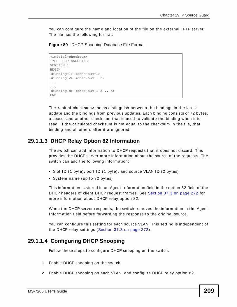
Chapter 29 IP Source Guard
MS-7206 User’s Guide 209
You can configure the name and location of the file on the external TFTP server. The file has the following format:
Figure 89 DHCP Snooping Database File Format
The <initial-checksum> helps distinguish between the bindings in the latest update and the bindings from previous updates. Each binding consists of 72 bytes, a space, and another checksum that is used to validate the binding when it is read. If the calculated checksum is not equal to the checksum in the file, that binding and all others after it are ignored.
29.1.1.3 DHCP Relay Option 82 InformationThe switch can add information to DHCP requests that it does not discard. This provides the DHCP server more information about the source of the requests. The switch can add the following information:
• Slot ID (1 byte), port ID (1 byte), and source VLAN ID (2 bytes)
• System name (up to 32 bytes)
This information is stored in an Agent Information field in the option 82 field of the DHCP headers of client DHCP request frames. See Section 37.3 on page 272 for more information about DHCP relay option 82.
When the DHCP server responds, the switch removes the information in the Agent Information field before forwarding the response to the original source.
You can configure this setting for each source VLAN. This setting is independent of the DHCP relay settings (Section 37.3 on page 272).
29.1.1.4 Configuring DHCP SnoopingFollow these steps to configure DHCP snooping on the switch.
1 Enable DHCP snooping on the switch.
2 Enable DHCP snooping on each VLAN, and configure DHCP relay option 82.
<initial-checksum>TYPE DHCP-SNOOPINGVERSION 1BEGIN<binding-1> <checksum-1><binding-2> <checksum-1-2>......<binding-n> <checksum-1-2-..-n>END
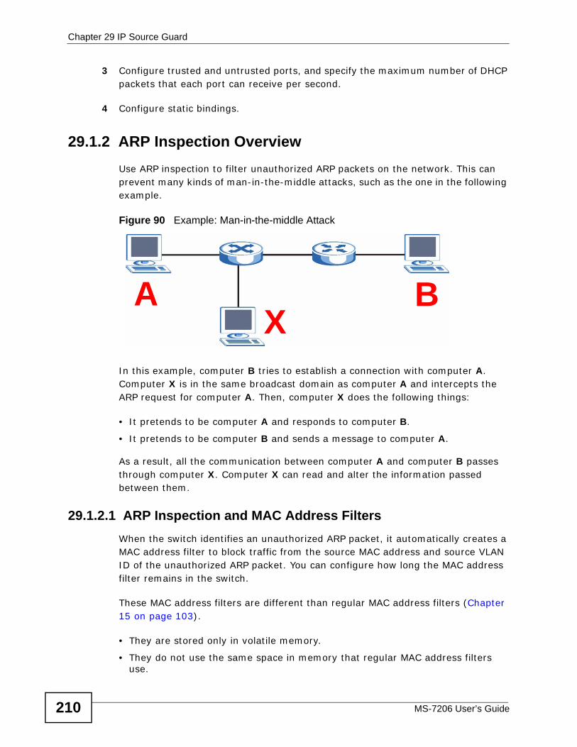
Chapter 29 IP Source Guard
MS-7206 User’s Guide210
3 Configure trusted and untrusted ports, and specify the maximum number of DHCP packets that each port can receive per second.
4 Configure static bindings.
29.1.2 ARP Inspection OverviewUse ARP inspection to filter unauthorized ARP packets on the network. This can prevent many kinds of man-in-the-middle attacks, such as the one in the following example.
Figure 90 Example: Man-in-the-middle Attack
In this example, computer B tries to establish a connection with computer A. Computer X is in the same broadcast domain as computer A and intercepts the ARP request for computer A. Then, computer X does the following things:
• It pretends to be computer A and responds to computer B.
• It pretends to be computer B and sends a message to computer A.
As a result, all the communication between computer A and computer B passes through computer X. Computer X can read and alter the information passed between them.
29.1.2.1 ARP Inspection and MAC Address FiltersWhen the switch identifies an unauthorized ARP packet, it automatically creates a MAC address filter to block traffic from the source MAC address and source VLAN ID of the unauthorized ARP packet. You can configure how long the MAC address filter remains in the switch.
These MAC address filters are different than regular MAC address filters (Chapter 15 on page 103).
• They are stored only in volatile memory.
• They do not use the same space in memory that regular MAC address filters use.
AX
B
Chapter 29 IP Source Guard
MS-7206 User’s Guide 211
• They appear only in the ARP Inspection screens and commands, not in the MAC address filtering screen and commands.
29.1.2.2 Trusted vs. Untrusted PortsEvery port is either a trusted port or an untrusted port for ARP inspection. This setting is independent of the trusted/untrusted setting for DHCP snooping. You can also specify the maximum rate at which the switch receives ARP packets on untrusted ports.
The switch does not discard ARP packets on trusted ports for any reason.
The switch discards ARP packets on untrusted ports in the following situations:
• The sender’s information in the ARP packet does not match any of the current bindings.
• The rate at which ARP packets arrive is too high.
29.1.2.3 SyslogThe switch can send syslog messages to the specified syslog server (Chapter 42 on page 323) when it forwards or discards ARP packets. The switch can consolidate log messages and send log messages in batches to make this mechanism more efficient.
29.1.2.4 Configuring ARP InspectionFollow these steps to configure ARP inspection on the switch.
1 Configure DHCP snooping. See Section 29.1.1.4 on page 209.
Note: It is recommended you enable DHCP snooping at least one day before you enable ARP inspection so that the switch has enough time to build the binding table.
2 Enable ARP inspection on each VLAN.
3 Configure trusted and untrusted ports, and specify the maximum number of ARP packets that each port can receive per second.
29.2 IP Source GuardUse this screen to look at the current bindings for DHCP snooping and ARP inspection. Bindings are used by DHCP snooping and ARP inspection to distinguish between authorized and unauthorized packets in the network. The switch learns
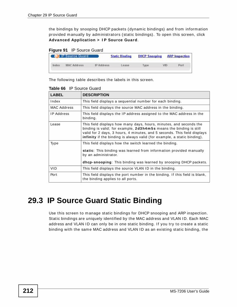
Chapter 29 IP Source Guard
MS-7206 User’s Guide212
the bindings by snooping DHCP packets (dynamic bindings) and from information provided manually by administrators (static bindings). To open this screen, click Advanced Application > IP Source Guard.
Figure 91 IP Source Guard
The following table describes the labels in this screen.
29.3 IP Source Guard Static BindingUse this screen to manage static bindings for DHCP snooping and ARP inspection. Static bindings are uniquely identified by the MAC address and VLAN ID. Each MAC address and VLAN ID can only be in one static binding. If you try to create a static binding with the same MAC address and VLAN ID as an existing static binding, the
Table 66 IP Source GuardLABEL DESCRIPTIONIndex This field displays a sequential number for each binding.
MAC Address This field displays the source MAC address in the binding.
IP Address This field displays the IP address assigned to the MAC address in the binding.
Lease This field displays how many days, hours, minutes, and seconds the binding is valid; for example, 2d3h4m5s means the binding is still valid for 2 days, 3 hours, 4 minutes, and 5 seconds. This field displays infinity if the binding is always valid (for example, a static binding).
Type This field displays how the switch learned the binding.
static: This binding was learned from information provided manually by an administrator.
dhcp-snooping: This binding was learned by snooping DHCP packets.
VID This field displays the source VLAN ID in the binding.
Port This field displays the port number in the binding. If this field is blank, the binding applies to all ports.
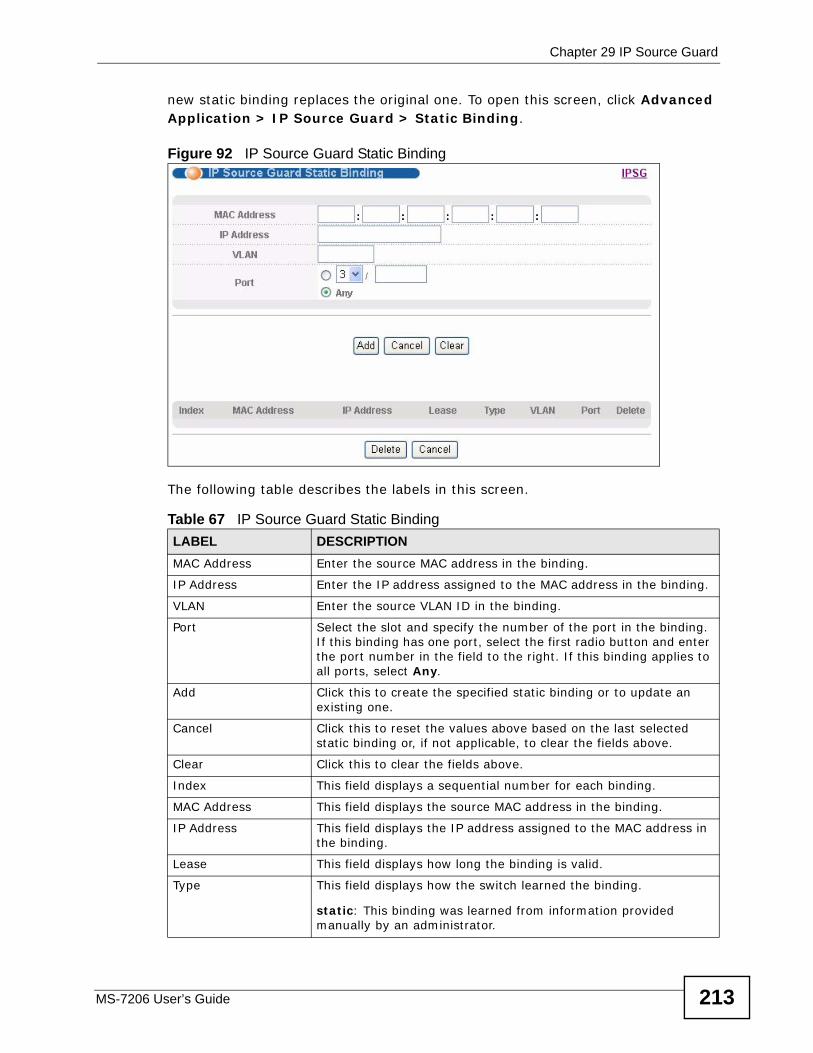
Chapter 29 IP Source Guard
MS-7206 User’s Guide 213
new static binding replaces the original one. To open this screen, click Advanced Application > IP Source Guard > Static Binding.
Figure 92 IP Source Guard Static Binding
The following table describes the labels in this screen.
Table 67 IP Source Guard Static BindingLABEL DESCRIPTIONMAC Address Enter the source MAC address in the binding.
IP Address Enter the IP address assigned to the MAC address in the binding.
VLAN Enter the source VLAN ID in the binding.
Port Select the slot and specify the number of the port in the binding. If this binding has one port, select the first radio button and enter the port number in the field to the right. If this binding applies to all ports, select Any.
Add Click this to create the specified static binding or to update an existing one.
Cancel Click this to reset the values above based on the last selected static binding or, if not applicable, to clear the fields above.
Clear Click this to clear the fields above.
Index This field displays a sequential number for each binding.
MAC Address This field displays the source MAC address in the binding.
IP Address This field displays the IP address assigned to the MAC address in the binding.
Lease This field displays how long the binding is valid.
Type This field displays how the switch learned the binding.
static: This binding was learned from information provided manually by an administrator.
Chapter 29 IP Source Guard
MS-7206 User’s Guide214
VLAN This field displays the source VLAN ID in the binding.
Port This field displays the port number in the binding. If this field is blank, the binding applies to all ports.
Delete Select this, and click Delete to remove the specified entry.
Cancel Click this to clear the Delete check boxes above.
Table 67 IP Source Guard Static Binding (continued)LABEL DESCRIPTION
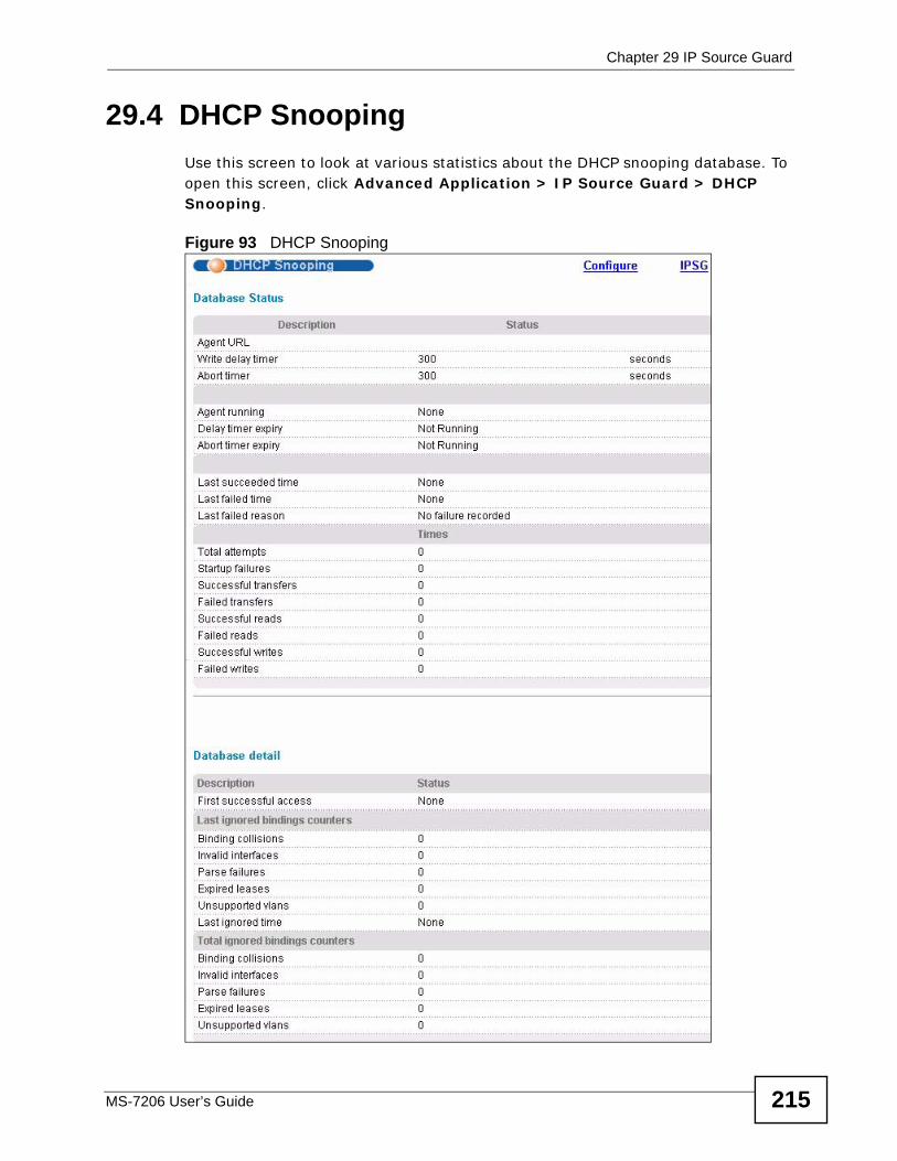
Chapter 29 IP Source Guard
MS-7206 User’s Guide 215
29.4 DHCP SnoopingUse this screen to look at various statistics about the DHCP snooping database. To open this screen, click Advanced Application > IP Source Guard > DHCP Snooping.
Figure 93 DHCP Snooping
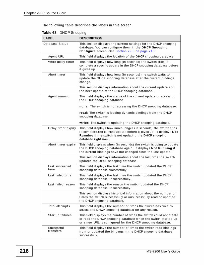
Chapter 29 IP Source Guard
MS-7206 User’s Guide216
The following table describes the labels in this screen.
Table 68 DHCP SnoopingLABEL DESCRIPTIONDatabase Status This section displays the current settings for the DHCP snooping
database. You can configure them in the DHCP Snooping Configure screen. See Section 29.5 on page 218.
Agent URL This field displays the location of the DHCP snooping database.
Write delay timer This field displays how long (in seconds) the switch tries to complete a specific update in the DHCP snooping database before it gives up.
Abort timer This field displays how long (in seconds) the switch waits to update the DHCP snooping database after the current bindings change.
This section displays information about the current update and the next update of the DHCP snooping database.
Agent running This field displays the status of the current update or access of the DHCP snooping database.
none: The switch is not accessing the DHCP snooping database.
read: The switch is loading dynamic bindings from the DHCP snooping database.
write: The switch is updating the DHCP snooping database.
Delay timer expiry This field displays how much longer (in seconds) the switch tries to complete the current update before it gives up. It displays Not Running if the switch is not updating the DHCP snooping database right now.
Abort timer expiry This field displays when (in seconds) the switch is going to update the DHCP snooping database again. It displays Not Running if the current bindings have not changed since the last update.
This section displays information about the last time the switch updated the DHCP snooping database.
Last succeeded time
This field displays the last time the switch updated the DHCP snooping database successfully.
Last failed time This field displays the last time the switch updated the DHCP snooping database unsuccessfully.
Last failed reason This field displays the reason the switch updated the DHCP snooping database unsuccessfully.
This section displays historical information about the number of times the switch successfully or unsuccessfully read or updated the DHCP snooping database.
Total attempts This field displays the number of times the switch has tried to access the DHCP snooping database for any reason.
Startup failures This field displays the number of times the switch could not create or read the DHCP snooping database when the switch started up or a new URL is configured for the DHCP snooping database.
Successful transfers
This field displays the number of times the switch read bindings from or updated the bindings in the DHCP snooping database successfully.
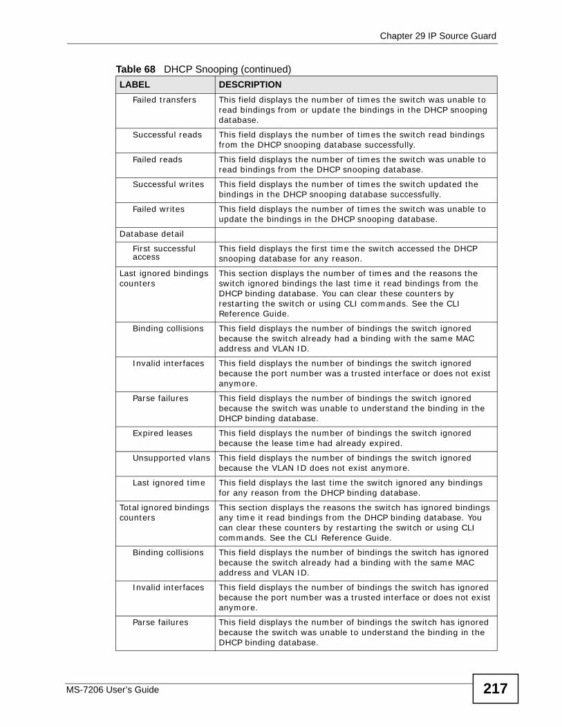
Chapter 29 IP Source Guard
MS-7206 User’s Guide 217
Failed transfers This field displays the number of times the switch was unable to read bindings from or update the bindings in the DHCP snooping database.
Successful reads This field displays the number of times the switch read bindings from the DHCP snooping database successfully.
Failed reads This field displays the number of times the switch was unable to read bindings from the DHCP snooping database.
Successful writes This field displays the number of times the switch updated the bindings in the DHCP snooping database successfully.
Failed writes This field displays the number of times the switch was unable to update the bindings in the DHCP snooping database.
Database detail
First successful access
This field displays the first time the switch accessed the DHCP snooping database for any reason.
Last ignored bindings counters
This section displays the number of times and the reasons the switch ignored bindings the last time it read bindings from the DHCP binding database. You can clear these counters by restarting the switch or using CLI commands. See the CLI Reference Guide.
Binding collisions This field displays the number of bindings the switch ignored because the switch already had a binding with the same MAC address and VLAN ID.
Invalid interfaces This field displays the number of bindings the switch ignored because the port number was a trusted interface or does not exist anymore.
Parse failures This field displays the number of bindings the switch ignored because the switch was unable to understand the binding in the DHCP binding database.
Expired leases This field displays the number of bindings the switch ignored because the lease time had already expired.
Unsupported vlans This field displays the number of bindings the switch ignored because the VLAN ID does not exist anymore.
Last ignored time This field displays the last time the switch ignored any bindings for any reason from the DHCP binding database.
Total ignored bindings counters
This section displays the reasons the switch has ignored bindings any time it read bindings from the DHCP binding database. You can clear these counters by restarting the switch or using CLI commands. See the CLI Reference Guide.
Binding collisions This field displays the number of bindings the switch has ignored because the switch already had a binding with the same MAC address and VLAN ID.
Invalid interfaces This field displays the number of bindings the switch has ignored because the port number was a trusted interface or does not exist anymore.
Parse failures This field displays the number of bindings the switch has ignored because the switch was unable to understand the binding in the DHCP binding database.
Table 68 DHCP Snooping (continued)LABEL DESCRIPTION
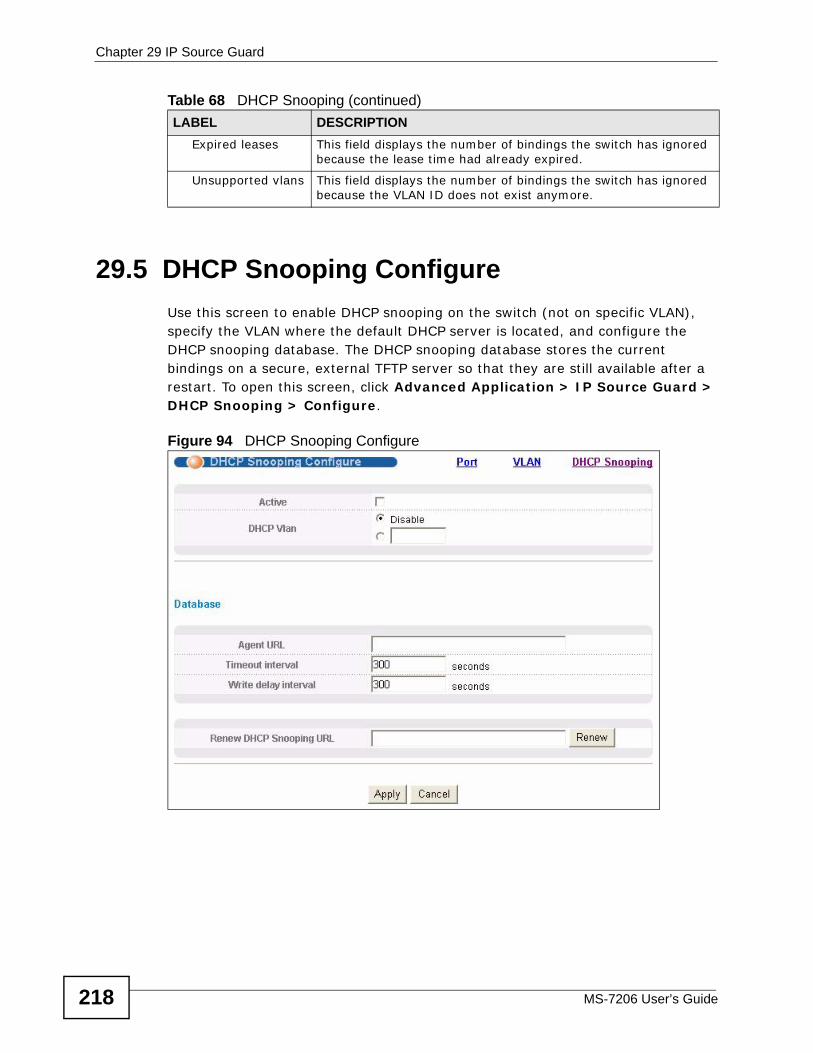
Chapter 29 IP Source Guard
MS-7206 User’s Guide218
29.5 DHCP Snooping ConfigureUse this screen to enable DHCP snooping on the switch (not on specific VLAN), specify the VLAN where the default DHCP server is located, and configure the DHCP snooping database. The DHCP snooping database stores the current bindings on a secure, external TFTP server so that they are still available after a restart. To open this screen, click Advanced Application > IP Source Guard > DHCP Snooping > Configure.
Figure 94 DHCP Snooping Configure
Expired leases This field displays the number of bindings the switch has ignored because the lease time had already expired.
Unsupported vlans This field displays the number of bindings the switch has ignored because the VLAN ID does not exist anymore.
Table 68 DHCP Snooping (continued)LABEL DESCRIPTION
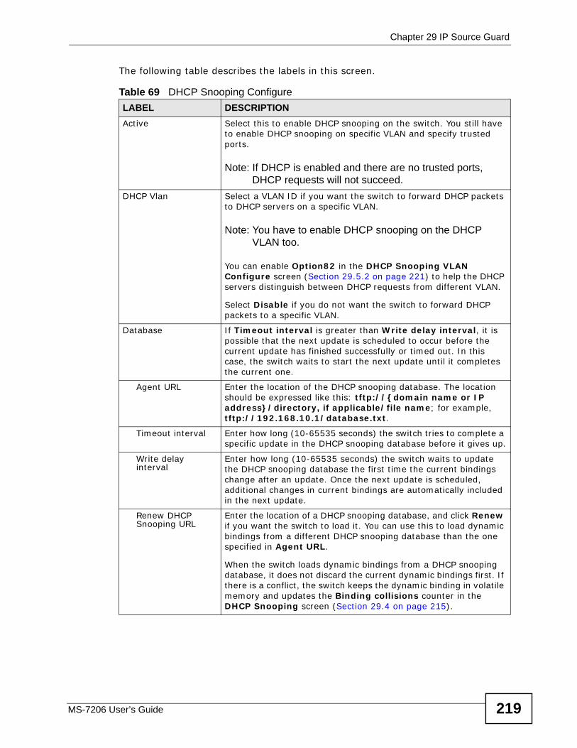
Chapter 29 IP Source Guard
MS-7206 User’s Guide 219
The following table describes the labels in this screen.
Table 69 DHCP Snooping ConfigureLABEL DESCRIPTIONActive Select this to enable DHCP snooping on the switch. You still have
to enable DHCP snooping on specific VLAN and specify trusted ports.
Note: If DHCP is enabled and there are no trusted ports, DHCP requests will not succeed.
DHCP Vlan Select a VLAN ID if you want the switch to forward DHCP packets to DHCP servers on a specific VLAN.
Note: You have to enable DHCP snooping on the DHCP VLAN too.
You can enable Option82 in the DHCP Snooping VLAN Configure screen (Section 29.5.2 on page 221) to help the DHCP servers distinguish between DHCP requests from different VLAN.
Select Disable if you do not want the switch to forward DHCP packets to a specific VLAN.
Database If Timeout interval is greater than Write delay interval, it is possible that the next update is scheduled to occur before the current update has finished successfully or timed out. In this case, the switch waits to start the next update until it completes the current one.
Agent URL Enter the location of the DHCP snooping database. The location should be expressed like this: tftp://{domain name or IP address}/directory, if applicable/file name; for example, tftp://192.168.10.1/database.txt.
Timeout interval Enter how long (10-65535 seconds) the switch tries to complete a specific update in the DHCP snooping database before it gives up.
Write delay interval
Enter how long (10-65535 seconds) the switch waits to update the DHCP snooping database the first time the current bindings change after an update. Once the next update is scheduled, additional changes in current bindings are automatically included in the next update.
Renew DHCP Snooping URL
Enter the location of a DHCP snooping database, and click Renew if you want the switch to load it. You can use this to load dynamic bindings from a different DHCP snooping database than the one specified in Agent URL.
When the switch loads dynamic bindings from a DHCP snooping database, it does not discard the current dynamic bindings first. If there is a conflict, the switch keeps the dynamic binding in volatile memory and updates the Binding collisions counter in the DHCP Snooping screen (Section 29.4 on page 215).
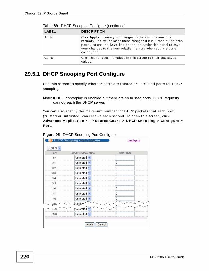
Chapter 29 IP Source Guard
MS-7206 User’s Guide220
29.5.1 DHCP Snooping Port ConfigureUse this screen to specify whether ports are trusted or untrusted ports for DHCP snooping.
Note: If DHCP snooping is enabled but there are no trusted ports, DHCP requests cannot reach the DHCP server.
You can also specify the maximum number for DHCP packets that each port (trusted or untrusted) can receive each second. To open this screen, click Advanced Application > IP Source Guard > DHCP Snooping > Configure > Port.
Figure 95 DHCP Snooping Port Configure
Apply Click Apply to save your changes to the switch’s run-time memory. The switch loses these changes if it is turned off or loses power, so use the Save link on the top navigation panel to save your changes to the non-volatile memory when you are done configuring.
Cancel Click this to reset the values in this screen to their last-saved values.
Table 69 DHCP Snooping Configure (continued)LABEL DESCRIPTION
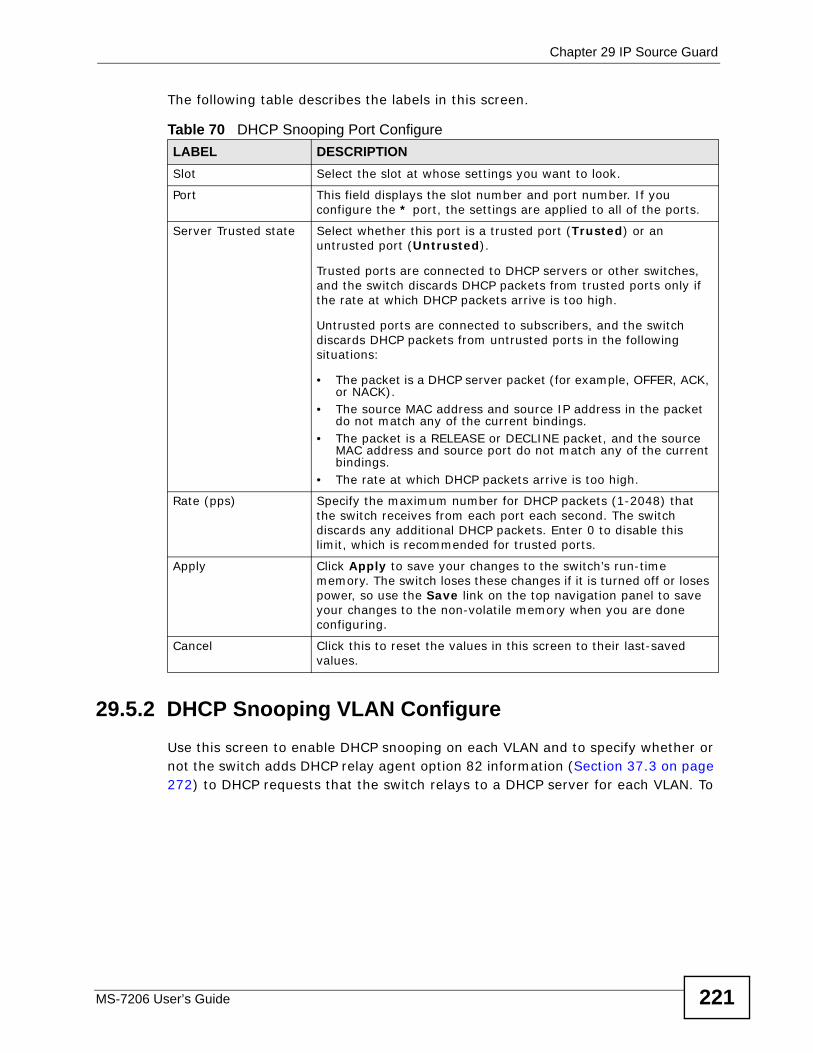
Chapter 29 IP Source Guard
MS-7206 User’s Guide 221
The following table describes the labels in this screen.
29.5.2 DHCP Snooping VLAN ConfigureUse this screen to enable DHCP snooping on each VLAN and to specify whether or not the switch adds DHCP relay agent option 82 information (Section 37.3 on page 272) to DHCP requests that the switch relays to a DHCP server for each VLAN. To
Table 70 DHCP Snooping Port ConfigureLABEL DESCRIPTIONSlot Select the slot at whose settings you want to look.
Port This field displays the slot number and port number. If you configure the * port, the settings are applied to all of the ports.
Server Trusted state Select whether this port is a trusted port (Trusted) or an untrusted port (Untrusted).
Trusted ports are connected to DHCP servers or other switches, and the switch discards DHCP packets from trusted ports only if the rate at which DHCP packets arrive is too high.
Untrusted ports are connected to subscribers, and the switch discards DHCP packets from untrusted ports in the following situations:
• The packet is a DHCP server packet (for example, OFFER, ACK, or NACK).
• The source MAC address and source IP address in the packet do not match any of the current bindings.
• The packet is a RELEASE or DECLINE packet, and the source MAC address and source port do not match any of the current bindings.
• The rate at which DHCP packets arrive is too high.
Rate (pps) Specify the maximum number for DHCP packets (1-2048) that the switch receives from each port each second. The switch discards any additional DHCP packets. Enter 0 to disable this limit, which is recommended for trusted ports.
Apply Click Apply to save your changes to the switch’s run-time memory. The switch loses these changes if it is turned off or loses power, so use the Save link on the top navigation panel to save your changes to the non-volatile memory when you are done configuring.
Cancel Click this to reset the values in this screen to their last-saved values.
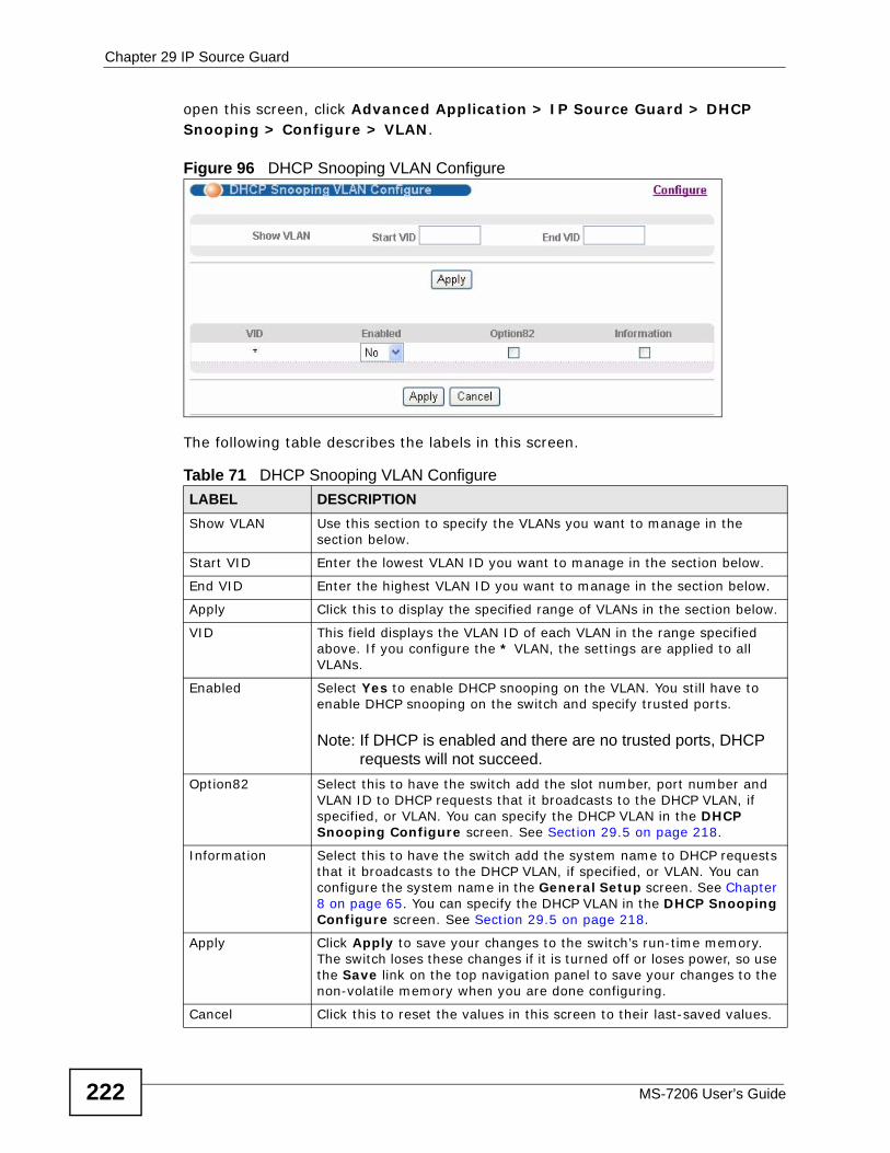
Chapter 29 IP Source Guard
MS-7206 User’s Guide222
open this screen, click Advanced Application > IP Source Guard > DHCP Snooping > Configure > VLAN.
Figure 96 DHCP Snooping VLAN Configure
The following table describes the labels in this screen.
Table 71 DHCP Snooping VLAN ConfigureLABEL DESCRIPTIONShow VLAN Use this section to specify the VLANs you want to manage in the
section below.
Start VID Enter the lowest VLAN ID you want to manage in the section below.
End VID Enter the highest VLAN ID you want to manage in the section below.
Apply Click this to display the specified range of VLANs in the section below.
VID This field displays the VLAN ID of each VLAN in the range specified above. If you configure the * VLAN, the settings are applied to all VLANs.
Enabled Select Yes to enable DHCP snooping on the VLAN. You still have to enable DHCP snooping on the switch and specify trusted ports.
Note: If DHCP is enabled and there are no trusted ports, DHCP requests will not succeed.
Option82 Select this to have the switch add the slot number, port number and VLAN ID to DHCP requests that it broadcasts to the DHCP VLAN, if specified, or VLAN. You can specify the DHCP VLAN in the DHCP Snooping Configure screen. See Section 29.5 on page 218.
Information Select this to have the switch add the system name to DHCP requests that it broadcasts to the DHCP VLAN, if specified, or VLAN. You can configure the system name in the General Setup screen. See Chapter 8 on page 65. You can specify the DHCP VLAN in the DHCP Snooping Configure screen. See Section 29.5 on page 218.
Apply Click Apply to save your changes to the switch’s run-time memory. The switch loses these changes if it is turned off or loses power, so use the Save link on the top navigation panel to save your changes to the non-volatile memory when you are done configuring.
Cancel Click this to reset the values in this screen to their last-saved values.
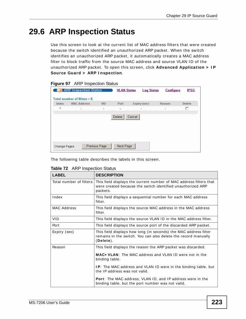
Chapter 29 IP Source Guard
MS-7206 User’s Guide 223
29.6 ARP Inspection StatusUse this screen to look at the current list of MAC address filters that were created because the switch identified an unauthorized ARP packet. When the switch identifies an unauthorized ARP packet, it automatically creates a MAC address filter to block traffic from the source MAC address and source VLAN ID of the unauthorized ARP packet. To open this screen, click Advanced Application > IP Source Guard > ARP Inspection.
Figure 97 ARP Inspection Status
The following table describes the labels in this screen.
Table 72 ARP Inspection StatusLABEL DESCRIPTIONTotal number of filters This field displays the current number of MAC address filters that
were created because the switch identified unauthorized ARP packets.
Index This field displays a sequential number for each MAC address filter.
MAC Address This field displays the source MAC address in the MAC address filter.
VID This field displays the source VLAN ID in the MAC address filter.
Port This field displays the source port of the discarded ARP packet.
Expiry (sec) This field displays how long (in seconds) the MAC address filter remains in the switch. You can also delete the record manually (Delete).
Reason This field displays the reason the ARP packet was discarded.
MAC+VLAN: The MAC address and VLAN ID were not in the binding table.
IP: The MAC address and VLAN ID were in the binding table, but the IP address was not valid.
Port: The MAC address, VLAN ID, and IP address were in the binding table, but the port number was not valid.
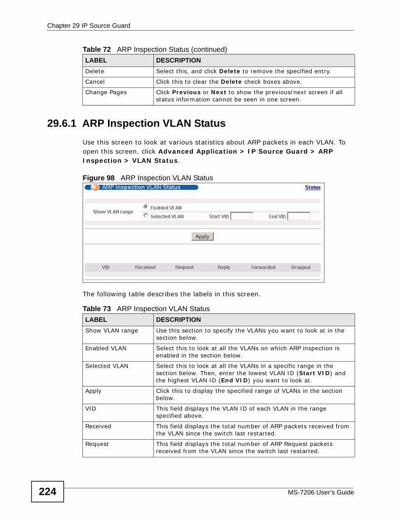
Chapter 29 IP Source Guard
MS-7206 User’s Guide224
29.6.1 ARP Inspection VLAN StatusUse this screen to look at various statistics about ARP packets in each VLAN. To open this screen, click Advanced Application > IP Source Guard > ARP Inspection > VLAN Status.
Figure 98 ARP Inspection VLAN Status
The following table describes the labels in this screen.
Delete Select this, and click Delete to remove the specified entry.
Cancel Click this to clear the Delete check boxes above.
Change Pages Click Previous or Next to show the previous/next screen if all status information cannot be seen in one screen.
Table 72 ARP Inspection Status (continued)LABEL DESCRIPTION
Table 73 ARP Inspection VLAN StatusLABEL DESCRIPTIONShow VLAN range Use this section to specify the VLANs you want to look at in the
section below.
Enabled VLAN Select this to look at all the VLANs on which ARP inspection is enabled in the section below.
Selected VLAN Select this to look at all the VLANs in a specific range in the section below. Then, enter the lowest VLAN ID (Start VID) and the highest VLAN ID (End VID) you want to look at.
Apply Click this to display the specified range of VLANs in the section below.
VID This field displays the VLAN ID of each VLAN in the range specified above.
Received This field displays the total number of ARP packets received from the VLAN since the switch last restarted.
Request This field displays the total number of ARP Request packets received from the VLAN since the switch last restarted.
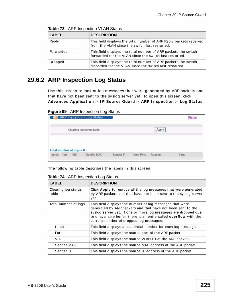
Chapter 29 IP Source Guard
MS-7206 User’s Guide 225
29.6.2 ARP Inspection Log StatusUse this screen to look at log messages that were generated by ARP packets and that have not been sent to the syslog server yet. To open this screen, click Advanced Application > IP Source Guard > ARP Inspection > Log Status.
Figure 99 ARP Inspection Log Status
The following table describes the labels in this screen.
Reply This field displays the total number of ARP Reply packets received from the VLAN since the switch last restarted.
Forwarded This field displays the total number of ARP packets the switch forwarded for the VLAN since the switch last restarted.
Dropped This field displays the total number of ARP packets the switch discarded for the VLAN since the switch last restarted.
Table 73 ARP Inspection VLAN StatusLABEL DESCRIPTION
Table 74 ARP Inspection Log StatusLABEL DESCRIPTIONClearing log status table
Click Apply to remove all the log messages that were generated by ARP packets and that have not been sent to the syslog server yet.
Total number of logs This field displays the number of log messages that were generated by ARP packets and that have not been sent to the syslog server yet. If one or more log messages are dropped due to unavailable buffer, there is an entry called overflow with the current number of dropped log messages.
Index This field displays a sequential number for each log message.
Port This field displays the source port of the ARP packet.
VID This field displays the source VLAN ID of the ARP packet.
Sender MAC This field displays the source MAC address of the ARP packet.
Sender IP This field displays the source IP address of the ARP packet.
Chapter 29 IP Source Guard
MS-7206 User’s Guide226
29.7 ARP Inspection ConfigureUse this screen to enable ARP inspection on the switch. You can also configure the length of time the switch stores records of discarded ARP packets and global
Num Pkts This field displays the number of ARP packets that were consolidated into this log message. The switch consolidates identical log messages generated by ARP packets in the log consolidation interval into one log message. You can configure this interval in the ARP Inspection Configure screen. See Section 29.7 on page 226.
Reason This field displays the reason the log message was generated.
dhcp deny: An ARP packet was discarded because it violated a dynamic binding with the same MAC address and VLAN ID.
static deny: An ARP packet was discarded because it violated a static binding with the same MAC address and VLAN ID.
deny: An ARP packet was discarded because there were no bindings with the same MAC address and VLAN ID.
dhcp permit: An ARP packet was forwarded because it matched a dynamic binding.
static permit: An ARP packet was forwarded because it matched a static binding.
In the ARP Inspection VLAN Configure screen, you can configure the switch to generate log messages when ARP packets are discarded or forwarded based on the VLAN ID of the ARP packet. See Section 29.7.2 on page 230.
Time This field displays when the log message was generated.
Table 74 ARP Inspection Log Status (continued)LABEL DESCRIPTION
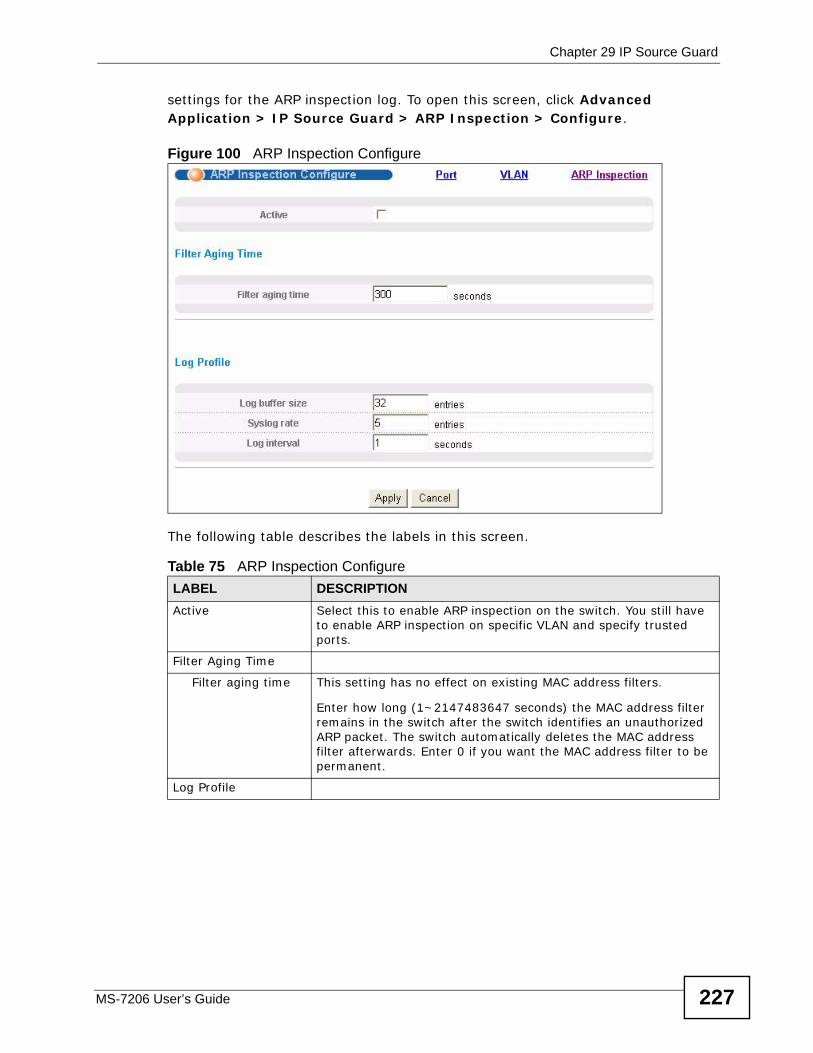
Chapter 29 IP Source Guard
MS-7206 User’s Guide 227
settings for the ARP inspection log. To open this screen, click Advanced Application > IP Source Guard > ARP Inspection > Configure.
Figure 100 ARP Inspection Configure
The following table describes the labels in this screen.
Table 75 ARP Inspection ConfigureLABEL DESCRIPTIONActive Select this to enable ARP inspection on the switch. You still have
to enable ARP inspection on specific VLAN and specify trusted ports.
Filter Aging Time
Filter aging time This setting has no effect on existing MAC address filters.
Enter how long (1~2147483647 seconds) the MAC address filter remains in the switch after the switch identifies an unauthorized ARP packet. The switch automatically deletes the MAC address filter afterwards. Enter 0 if you want the MAC address filter to be permanent.
Log Profile
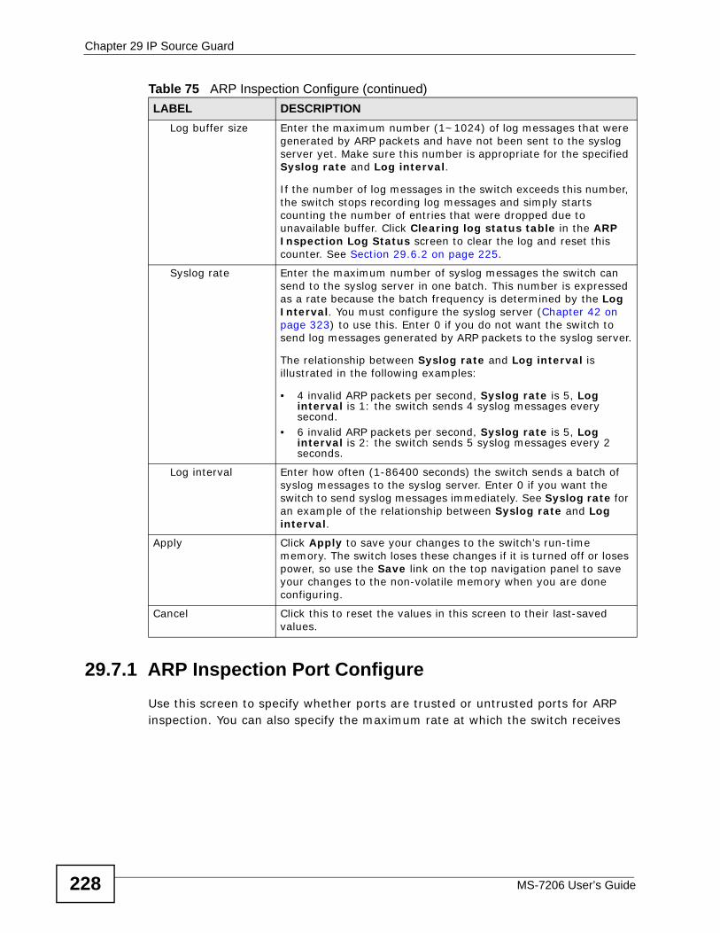
Chapter 29 IP Source Guard
MS-7206 User’s Guide228
29.7.1 ARP Inspection Port ConfigureUse this screen to specify whether ports are trusted or untrusted ports for ARP inspection. You can also specify the maximum rate at which the switch receives
Log buffer size Enter the maximum number (1~1024) of log messages that were generated by ARP packets and have not been sent to the syslog server yet. Make sure this number is appropriate for the specified Syslog rate and Log interval.
If the number of log messages in the switch exceeds this number, the switch stops recording log messages and simply starts counting the number of entries that were dropped due to unavailable buffer. Click Clearing log status table in the ARP Inspection Log Status screen to clear the log and reset this counter. See Section 29.6.2 on page 225.
Syslog rate Enter the maximum number of syslog messages the switch can send to the syslog server in one batch. This number is expressed as a rate because the batch frequency is determined by the Log Interval. You must configure the syslog server (Chapter 42 on page 323) to use this. Enter 0 if you do not want the switch to send log messages generated by ARP packets to the syslog server.
The relationship between Syslog rate and Log interval is illustrated in the following examples:
• 4 invalid ARP packets per second, Syslog rate is 5, Log interval is 1: the switch sends 4 syslog messages every second.
• 6 invalid ARP packets per second, Syslog rate is 5, Log interval is 2: the switch sends 5 syslog messages every 2 seconds.
Log interval Enter how often (1-86400 seconds) the switch sends a batch of syslog messages to the syslog server. Enter 0 if you want the switch to send syslog messages immediately. See Syslog rate for an example of the relationship between Syslog rate and Log interval.
Apply Click Apply to save your changes to the switch’s run-time memory. The switch loses these changes if it is turned off or loses power, so use the Save link on the top navigation panel to save your changes to the non-volatile memory when you are done configuring.
Cancel Click this to reset the values in this screen to their last-saved values.
Table 75 ARP Inspection Configure (continued)LABEL DESCRIPTION
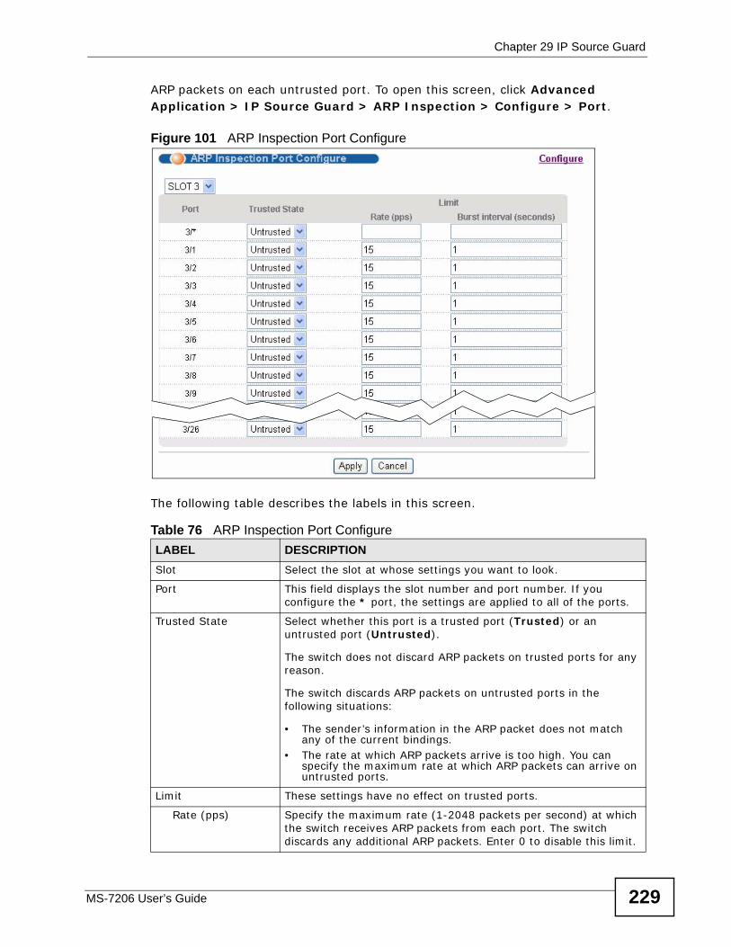
Chapter 29 IP Source Guard
MS-7206 User’s Guide 229
ARP packets on each untrusted port. To open this screen, click Advanced Application > IP Source Guard > ARP Inspection > Configure > Port.
Figure 101 ARP Inspection Port Configure
The following table describes the labels in this screen.
Table 76 ARP Inspection Port ConfigureLABEL DESCRIPTIONSlot Select the slot at whose settings you want to look.
Port This field displays the slot number and port number. If you configure the * port, the settings are applied to all of the ports.
Trusted State Select whether this port is a trusted port (Trusted) or an untrusted port (Untrusted).
The switch does not discard ARP packets on trusted ports for any reason.
The switch discards ARP packets on untrusted ports in the following situations:
• The sender’s information in the ARP packet does not match any of the current bindings.
• The rate at which ARP packets arrive is too high. You can specify the maximum rate at which ARP packets can arrive on untrusted ports.
Limit These settings have no effect on trusted ports.
Rate (pps) Specify the maximum rate (1-2048 packets per second) at which the switch receives ARP packets from each port. The switch discards any additional ARP packets. Enter 0 to disable this limit.
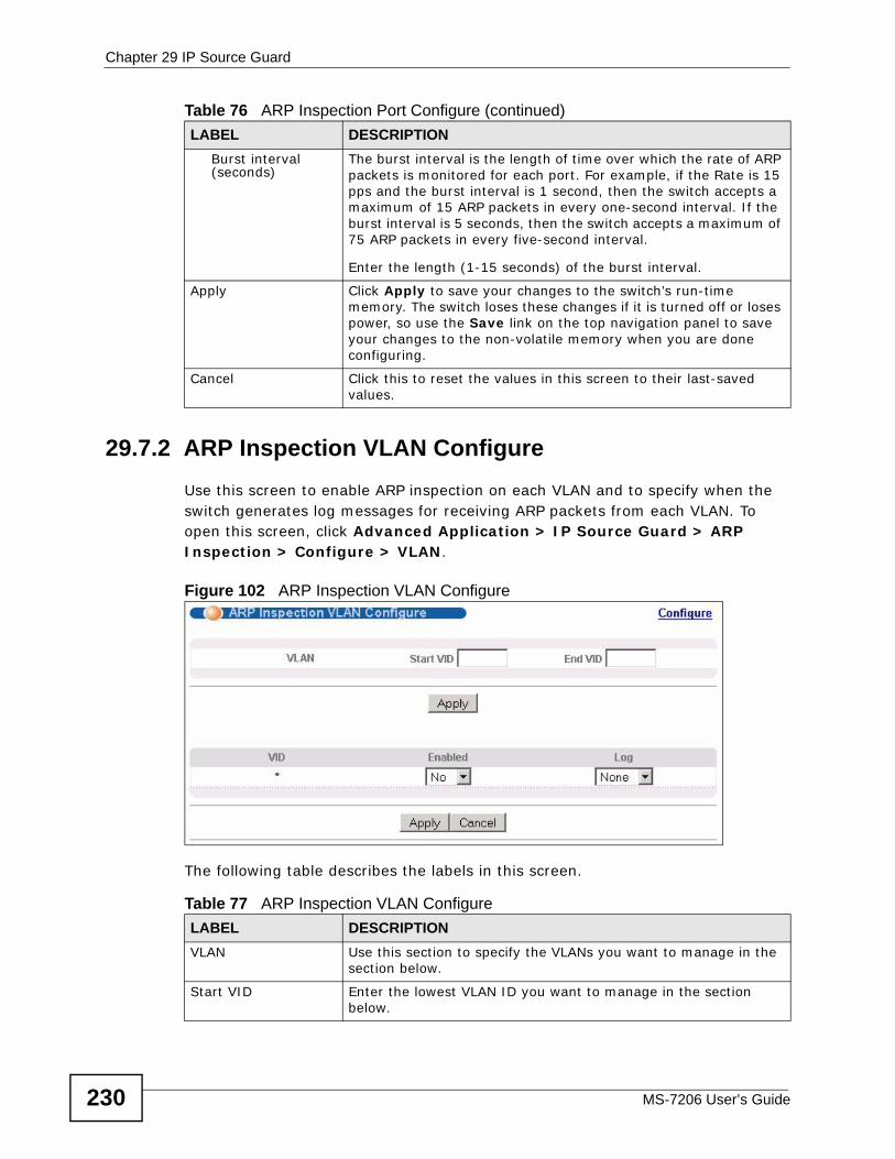
Chapter 29 IP Source Guard
MS-7206 User’s Guide230
29.7.2 ARP Inspection VLAN ConfigureUse this screen to enable ARP inspection on each VLAN and to specify when the switch generates log messages for receiving ARP packets from each VLAN. To open this screen, click Advanced Application > IP Source Guard > ARP Inspection > Configure > VLAN.
Figure 102 ARP Inspection VLAN Configure
The following table describes the labels in this screen.
Burst interval (seconds)
The burst interval is the length of time over which the rate of ARP packets is monitored for each port. For example, if the Rate is 15 pps and the burst interval is 1 second, then the switch accepts a maximum of 15 ARP packets in every one-second interval. If the burst interval is 5 seconds, then the switch accepts a maximum of 75 ARP packets in every five-second interval.
Enter the length (1-15 seconds) of the burst interval.
Apply Click Apply to save your changes to the switch’s run-time memory. The switch loses these changes if it is turned off or loses power, so use the Save link on the top navigation panel to save your changes to the non-volatile memory when you are done configuring.
Cancel Click this to reset the values in this screen to their last-saved values.
Table 76 ARP Inspection Port Configure (continued)LABEL DESCRIPTION
Table 77 ARP Inspection VLAN ConfigureLABEL DESCRIPTIONVLAN Use this section to specify the VLANs you want to manage in the
section below.
Start VID Enter the lowest VLAN ID you want to manage in the section below.
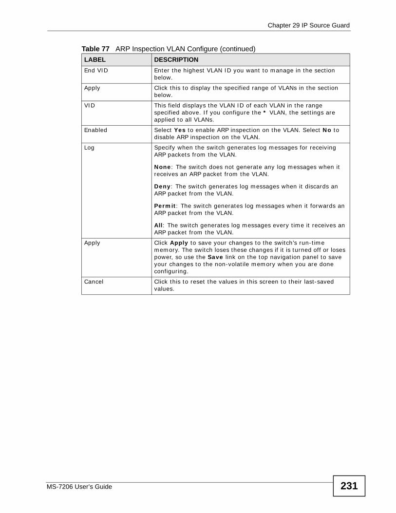
Chapter 29 IP Source Guard
MS-7206 User’s Guide 231
End VID Enter the highest VLAN ID you want to manage in the section below.
Apply Click this to display the specified range of VLANs in the section below.
VID This field displays the VLAN ID of each VLAN in the range specified above. If you configure the * VLAN, the settings are applied to all VLANs.
Enabled Select Yes to enable ARP inspection on the VLAN. Select No to disable ARP inspection on the VLAN.
Log Specify when the switch generates log messages for receiving ARP packets from the VLAN.
None: The switch does not generate any log messages when it receives an ARP packet from the VLAN.
Deny: The switch generates log messages when it discards an ARP packet from the VLAN.
Permit: The switch generates log messages when it forwards an ARP packet from the VLAN.
All: The switch generates log messages every time it receives an ARP packet from the VLAN.
Apply Click Apply to save your changes to the switch’s run-time memory. The switch loses these changes if it is turned off or loses power, so use the Save link on the top navigation panel to save your changes to the non-volatile memory when you are done configuring.
Cancel Click this to reset the values in this screen to their last-saved values.
Table 77 ARP Inspection VLAN Configure (continued)LABEL DESCRIPTION

Chapter 29 IP Source Guard
MS-7206 User’s Guide232
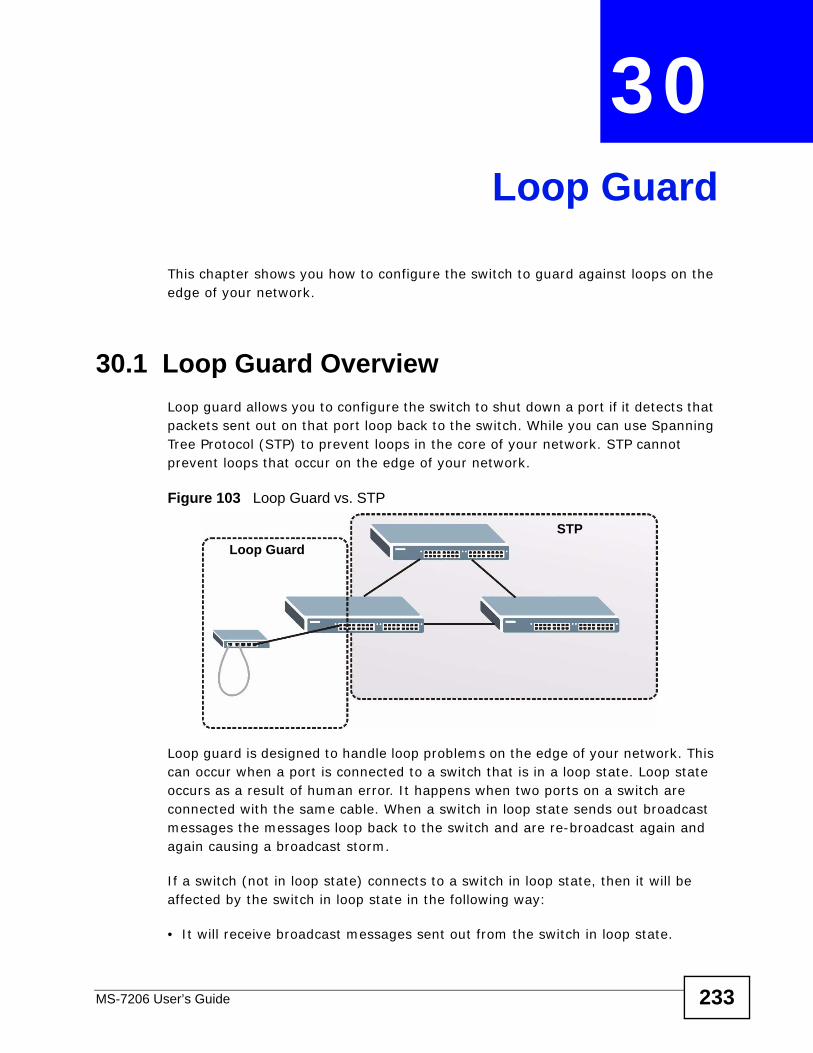
MS-7206 User’s Guide 233
CHAPTER 30 Loop Guard
This chapter shows you how to configure the switch to guard against loops on the edge of your network.
30.1 Loop Guard Overview Loop guard allows you to configure the switch to shut down a port if it detects that packets sent out on that port loop back to the switch. While you can use Spanning Tree Protocol (STP) to prevent loops in the core of your network. STP cannot prevent loops that occur on the edge of your network.
Figure 103 Loop Guard vs. STP
Loop guard is designed to handle loop problems on the edge of your network. This can occur when a port is connected to a switch that is in a loop state. Loop state occurs as a result of human error. It happens when two ports on a switch are connected with the same cable. When a switch in loop state sends out broadcast messages the messages loop back to the switch and are re-broadcast again and again causing a broadcast storm.
If a switch (not in loop state) connects to a switch in loop state, then it will be affected by the switch in loop state in the following way:
• It will receive broadcast messages sent out from the switch in loop state.
STPLoop Guard
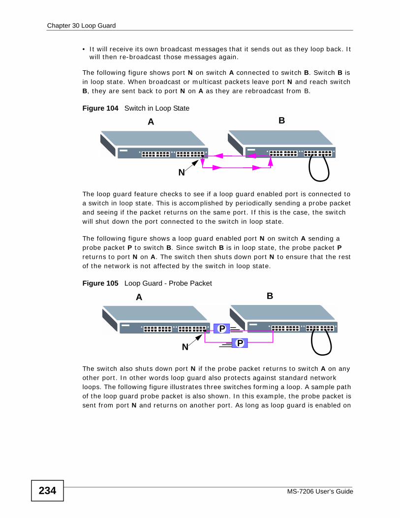
Chapter 30 Loop Guard
MS-7206 User’s Guide234
• It will receive its own broadcast messages that it sends out as they loop back. It will then re-broadcast those messages again.
The following figure shows port N on switch A connected to switch B. Switch B is in loop state. When broadcast or multicast packets leave port N and reach switch B, they are sent back to port N on A as they are rebroadcast from B.
Figure 104 Switch in Loop State
The loop guard feature checks to see if a loop guard enabled port is connected to a switch in loop state. This is accomplished by periodically sending a probe packet and seeing if the packet returns on the same port. If this is the case, the switch will shut down the port connected to the switch in loop state.
The following figure shows a loop guard enabled port N on switch A sending a probe packet P to switch B. Since switch B is in loop state, the probe packet P returns to port N on A. The switch then shuts down port N to ensure that the rest of the network is not affected by the switch in loop state.
Figure 105 Loop Guard - Probe Packet
The switch also shuts down port N if the probe packet returns to switch A on any other port. In other words loop guard also protects against standard network loops. The following figure illustrates three switches forming a loop. A sample path of the loop guard probe packet is also shown. In this example, the probe packet is sent from port N and returns on another port. As long as loop guard is enabled on
A B
N
A B
PP
N
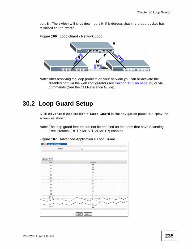
Chapter 30 Loop Guard
MS-7206 User’s Guide 235
port N. The switch will shut down port N if it detects that the probe packet has returned to the switch.
Figure 106 Loop Guard - Network Loop
Note: After resolving the loop problem on your network you can re-activate the disabled port via the web configurator (see Section 12.1 on page 79) or via commands (See the CLI Reference Guide).
30.2 Loop Guard Setup Click Advanced Application > Loop Guard in the navigation panel to display the screen as shown.
Note: The loop guard feature can not be enabled on the ports that have Spanning Tree Protocol (RSTP, MRSTP or MSTP) enabled.
Figure 107 Advanced Application > Loop Guard
A
P
PN
P
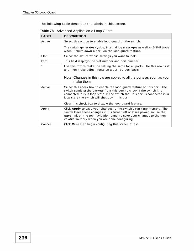
Chapter 30 Loop Guard
MS-7206 User’s Guide236
The following table describes the labels in this screen.
Table 78 Advanced Application > Loop Guard LABEL DESCRIPTIONActive Select this option to enable loop guard on the switch.
The switch generates syslog, internal log messages as well as SNMP traps when it shuts down a port via the loop guard feature.
Slot Select the slot at whose settings you want to look.
Port This field displays the slot number and port number.
* Use this row to make the setting the same for all ports. Use this row first and then make adjustments on a port-by-port basis.
Note: Changes in this row are copied to all the ports as soon as you make them.
Active Select this check box to enable the loop guard feature on this port. The switch sends probe packets from this port to check if the switch it is connected to is in loop state. If the switch that this port is connected is in loop state the switch will shut down this port.
Clear this check box to disable the loop guard feature.
Apply Click Apply to save your changes to the switch’s run-time memory. The switch loses these changes if it is turned off or loses power, so use the Save link on the top navigation panel to save your changes to the non-volatile memory when you are done configuring.
Cancel Click Cancel to begin configuring this screen afresh.

Chapter 30 Loop Guard
MS-7206 User’s Guide 237

Chapter 30 Loop Guard
MS-7206 User’s Guide238
239
PART VIP
Static Route (241)
RIP (243)
OSPF (245)
IGMP (257)
DVMRP (259)
Differentiated Services (263)
DHCP (271)
VRRP (281)

240
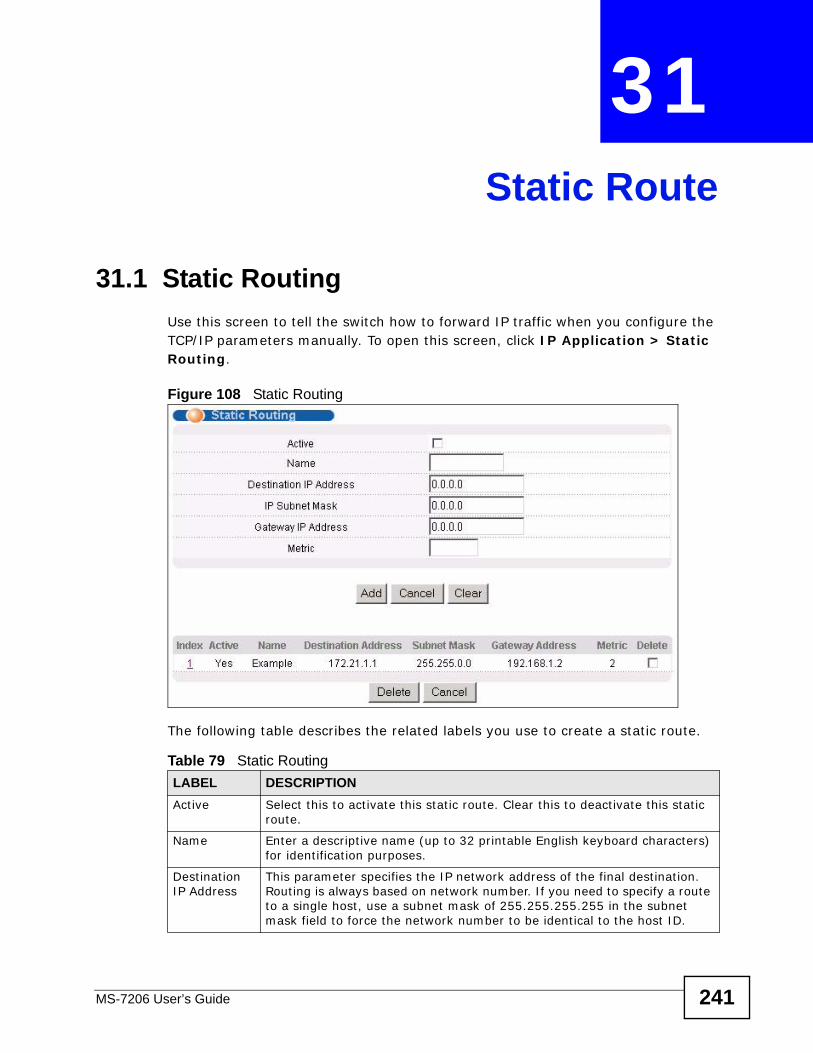
MS-7206 User’s Guide 241
CHAPTER 31 Static Route
31.1 Static Routing Use this screen to tell the switch how to forward IP traffic when you configure the TCP/IP parameters manually. To open this screen, click IP Application > Static Routing.
Figure 108 Static Routing
The following table describes the related labels you use to create a static route.
Table 79 Static RoutingLABEL DESCRIPTIONActive Select this to activate this static route. Clear this to deactivate this static
route.
Name Enter a descriptive name (up to 32 printable English keyboard characters) for identification purposes.
Destination IP Address
This parameter specifies the IP network address of the final destination. Routing is always based on network number. If you need to specify a route to a single host, use a subnet mask of 255.255.255.255 in the subnet mask field to force the network number to be identical to the host ID.
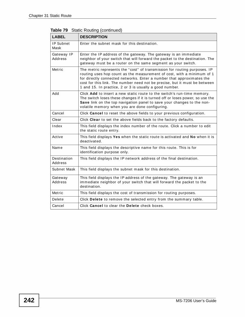
Chapter 31 Static Route
MS-7206 User’s Guide242
IP Subnet Mask
Enter the subnet mask for this destination.
Gateway IP Address
Enter the IP address of the gateway. The gateway is an immediate neighbor of your switch that will forward the packet to the destination. The gateway must be a router on the same segment as your switch.
Metric The metric represents the “cost” of transmission for routing purposes. IP routing uses hop count as the measurement of cost, with a minimum of 1 for directly connected networks. Enter a number that approximates the cost for this link. The number need not be precise, but it must be between 1 and 15. In practice, 2 or 3 is usually a good number.
Add Click Add to insert a new static route to the switch’s run-time memory. The switch loses these changes if it is turned off or loses power, so use the Save link on the top navigation panel to save your changes to the non-volatile memory when you are done configuring.
Cancel Click Cancel to reset the above fields to your previous configuration.
Clear Click Clear to set the above fields back to the factory defaults.
Index This field displays the index number of the route. Click a number to edit the static route entry.
Active This field displays Yes when the static route is activated and No when it is deactivated.
Name This field displays the descriptive name for this route. This is for identification purpose only.
Destination Address
This field displays the IP network address of the final destination.
Subnet Mask This field displays the subnet mask for this destination.
Gateway Address
This field displays the IP address of the gateway. The gateway is an immediate neighbor of your switch that will forward the packet to the destination.
Metric This field displays the cost of transmission for routing purposes.
Delete Click Delete to remove the selected entry from the summary table.
Cancel Click Cancel to clear the Delete check boxes.
Table 79 Static Routing (continued)LABEL DESCRIPTION
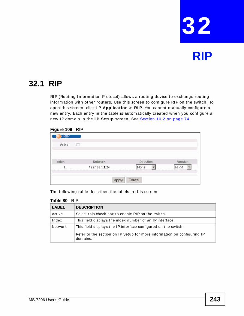
MS-7206 User’s Guide 243
CHAPTER 32 RIP
32.1 RIPRIP (Routing Information Protocol) allows a routing device to exchange routing information with other routers. Use this screen to configure RIP on the switch. To open this screen, click IP Application > RIP. You cannot manually configure a new entry. Each entry in the table is automatically created when you configure a new IP domain in the IP Setup screen. See Section 10.2 on page 74.
Figure 109 RIP
The following table describes the labels in this screen.
Table 80 RIP LABEL DESCRIPTIONActive Select this check box to enable RIP on the switch.
Index This field displays the index number of an IP interface.
Network This field displays the IP interface configured on the switch.
Refer to the section on IP Setup for more information on configuring IP domains.
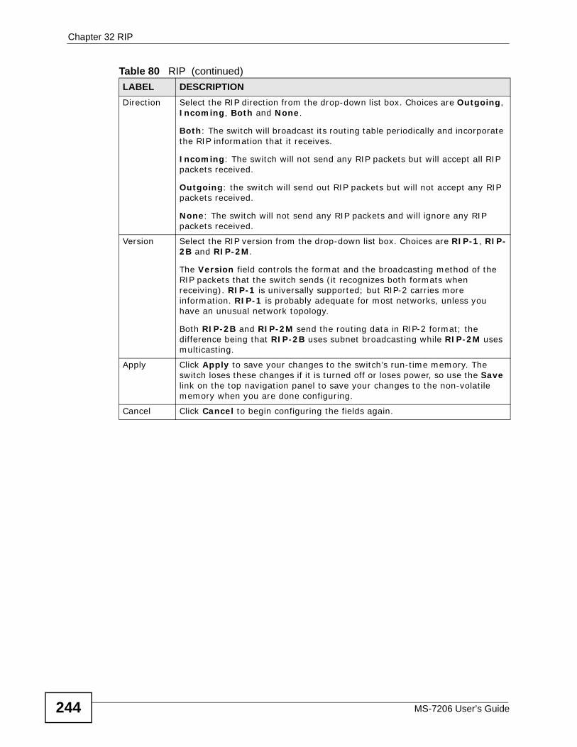
Chapter 32 RIP
MS-7206 User’s Guide244
Direction Select the RIP direction from the drop-down list box. Choices are Outgoing, Incoming, Both and None.
Both: The switch will broadcast its routing table periodically and incorporate the RIP information that it receives.
Incoming: The switch will not send any RIP packets but will accept all RIP packets received.
Outgoing: the switch will send out RIP packets but will not accept any RIP packets received.
None: The switch will not send any RIP packets and will ignore any RIP packets received.
Version Select the RIP version from the drop-down list box. Choices are RIP-1, RIP-2B and RIP-2M.
The Version field controls the format and the broadcasting method of the RIP packets that the switch sends (it recognizes both formats when receiving). RIP-1 is universally supported; but RIP-2 carries more information. RIP-1 is probably adequate for most networks, unless you have an unusual network topology.
Both RIP-2B and RIP-2M send the routing data in RIP-2 format; the difference being that RIP-2B uses subnet broadcasting while RIP-2M uses multicasting.
Apply Click Apply to save your changes to the switch’s run-time memory. The switch loses these changes if it is turned off or loses power, so use the Save link on the top navigation panel to save your changes to the non-volatile memory when you are done configuring.
Cancel Click Cancel to begin configuring the fields again.
Table 80 RIP (continued)LABEL DESCRIPTION
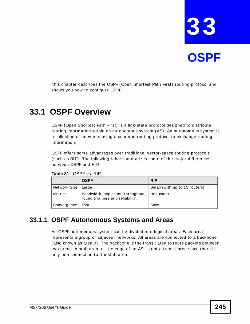
MS-7206 User’s Guide 245
CHAPTER 33 OSPF
This chapter describes the OSPF (Open Shortest Path First) routing protocol and shows you how to configure OSPF.
33.1 OSPF Overview OSPF (Open Shortest Path First) is a link-state protocol designed to distribute routing information within an autonomous system (AS). An autonomous system is a collection of networks using a common routing protocol to exchange routing information.
OSPF offers some advantages over traditional vector-space routing protocols (such as RIP). The following table summarizes some of the major differences between OSPF and RIP.
33.1.1 OSPF Autonomous Systems and AreasAn OSPF autonomous system can be divided into logical areas. Each area represents a group of adjacent networks. All areas are connected to a backbone (also known as area 0). The backbone is the transit area to route packets between two areas. A stub area, at the edge of an AS, is not a transit area since there is only one connection to the stub area.
Table 81 OSPF vs. RIP OSPF RIP
Network Size Large Small (with up to 15 routers)
Metrics Bandwidth, hop count, throughput, round trip time and reliability.
Hop count
Convergence Fast Slow
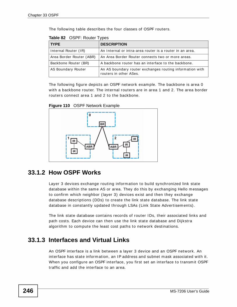
Chapter 33 OSPF
MS-7206 User’s Guide246
The following table describes the four classes of OSPF routers.
The following figure depicts an OSPF network example. The backbone is area 0 with a backbone router. The internal routers are in area 1 and 2. The area border routers connect area 1 and 2 to the backbone.
Figure 110 OSPF Network Example
33.1.2 How OSPF WorksLayer 3 devices exchange routing information to build synchronized link state database within the same AS or area. They do this by exchanging Hello messages to confirm which neighbor (layer 3) devices exist and then they exchange database descriptions (DDs) to create the link state database. The link state database in constantly updated through LSAs (Link State Advertisements).
The link state database contains records of router IDs, their associated links and path costs. Each device can then use the link state database and Dijkstra algorithm to compute the least cost paths to network destinations.
33.1.3 Interfaces and Virtual LinksAn OSPF interface is a link between a layer 3 device and an OSPF network. An interface has state information, an IP address and subnet mask associated with it. When you configure an OSPF interface, you first set an interface to transmit OSPF traffic and add the interface to an area.
Table 82 OSPF: Router Types TYPE DESCRIPTIONInternal Router (IR) An Internal or intra-area router is a router in an area.
Area Border Router (ABR) An Area Border Router connects two or more areas.
Backbone Router (BR) A backbone router has an interface to the backbone.
AS Boundary Router An AS boundary router exchanges routing information with routers in other ASes.
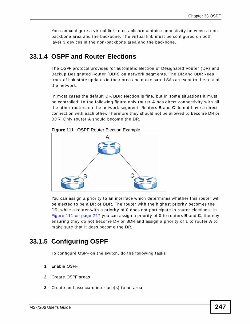
Chapter 33 OSPF
MS-7206 User’s Guide 247
You can configure a virtual link to establish/maintain connectivity between a non-backbone area and the backbone. The virtual link must be configured on both layer 3 devices in the non-backbone area and the backbone.
33.1.4 OSPF and Router ElectionsThe OSPF protocol provides for automatic election of Designated Router (DR) and Backup Designated Router (BDR) on network segments. The DR and BDR keep track of link state updates in their area and make sure LSAs are sent to the rest of the network.
In most cases the default DR/BDR election is fine, but in some situations it must be controlled. In the following figure only router A has direct connectivity with all the other routers on the network segment. Routers B and C do not have a direct connection with each other. Therefore they should not be allowed to become DR or BDR. Only router A should become the DR.
Figure 111 OSPF Router Election Example
You can assign a priority to an interface which determines whether this router will be elected to be a DR or BDR. The router with the highest priority becomes the DR, while a router with a priority of 0 does not participate in router elections. In Figure 111 on page 247 you can assign a priority of 0 to routers B and C, thereby ensuring they do not become DR or BDR and assign a priority of 1 to router A to make sure that it does become the DR.
33.1.5 Configuring OSPF To configure OSPF on the switch, do the following tasks
1 Enable OSPF
2 Create OSPF areas
3 Create and associate interface(s) to an area
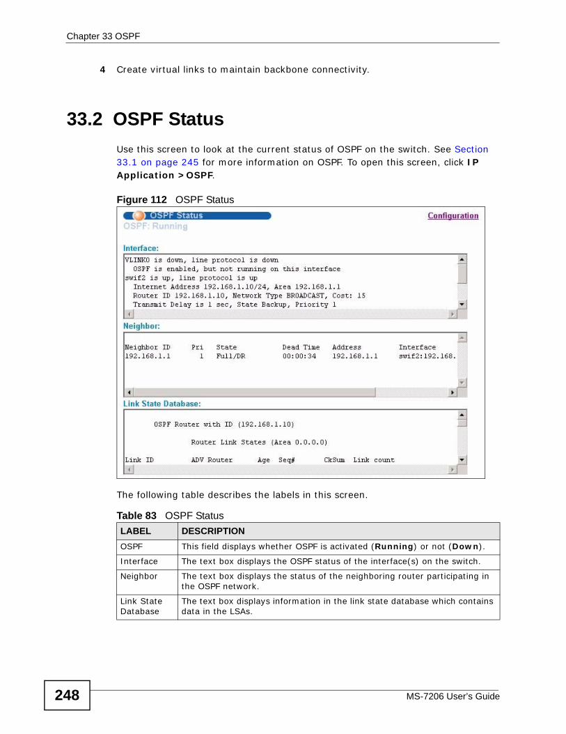
Chapter 33 OSPF
MS-7206 User’s Guide248
4 Create virtual links to maintain backbone connectivity.
33.2 OSPF Status Use this screen to look at the current status of OSPF on the switch. See Section 33.1 on page 245 for more information on OSPF. To open this screen, click IP Application >OSPF.
Figure 112 OSPF Status
The following table describes the labels in this screen.
Table 83 OSPF StatusLABEL DESCRIPTIONOSPF This field displays whether OSPF is activated (Running) or not (Down).
Interface The text box displays the OSPF status of the interface(s) on the switch.
Neighbor The text box displays the status of the neighboring router participating in the OSPF network.
Link State Database
The text box displays information in the link state database which contains data in the LSAs.
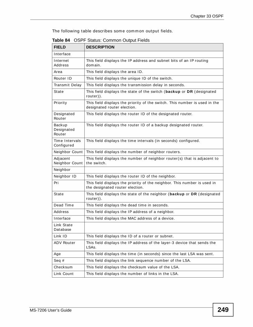
Chapter 33 OSPF
MS-7206 User’s Guide 249
The following table describes some common output fields.
Table 84 OSPF Status: Common Output Fields FIELD DESCRIPTIONInterface
Internet Address
This field displays the IP address and subnet bits of an IP routing domain.
Area This field displays the area ID.
Router ID This field displays the unique ID of the switch.
Transmit Delay This field displays the transmission delay in seconds.
State This field displays the state of the switch (backup or DR (designated router)).
Priority This field displays the priority of the switch. This number is used in the designated router election.
Designated Router
This field displays the router ID of the designated router.
Backup Designated Router
This field displays the router ID of a backup designated router.
Time Intervals Configured
This field displays the time intervals (in seconds) configured.
Neighbor Count This field displays the number of neighbor routers.
Adjacent Neighbor Count
This field displays the number of neighbor router(s) that is adjacent to the switch.
Neighbor
Neighbor ID This field displays the router ID of the neighbor.
Pri This field displays the priority of the neighbor. This number is used in the designated router election.
State This field displays the state of the neighbor (backup or DR (designated router)).
Dead Time This field displays the dead time in seconds.
Address This field displays the IP address of a neighbor.
Interface This field displays the MAC address of a device.
Link State Database
Link ID This field displays the ID of a router or subnet.
ADV Router This field displays the IP address of the layer-3 device that sends the LSAs.
Age This field displays the time (in seconds) since the last LSA was sent.
Seq # This field displays the link sequence number of the LSA.
Checksum This field displays the checksum value of the LSA.
Link Count This field displays the number of links in the LSA.
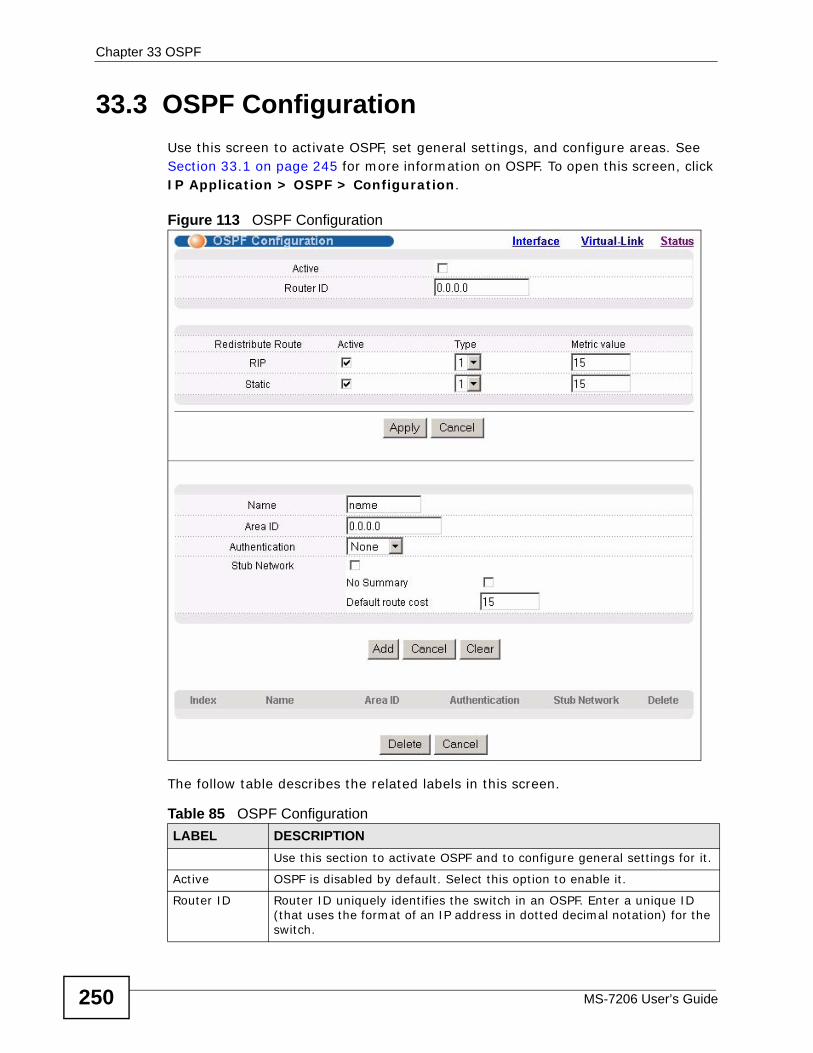
Chapter 33 OSPF
MS-7206 User’s Guide250
33.3 OSPF Configuration Use this screen to activate OSPF, set general settings, and configure areas. See Section 33.1 on page 245 for more information on OSPF. To open this screen, click IP Application > OSPF > Configuration.
Figure 113 OSPF Configuration
The follow table describes the related labels in this screen.
Table 85 OSPF ConfigurationLABEL DESCRIPTION
Use this section to activate OSPF and to configure general settings for it.
Active OSPF is disabled by default. Select this option to enable it.
Router ID Router ID uniquely identifies the switch in an OSPF. Enter a unique ID (that uses the format of an IP address in dotted decimal notation) for the switch.
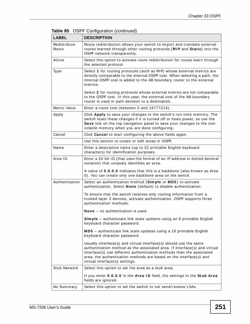
Chapter 33 OSPF
MS-7206 User’s Guide 251
Redistribute Route
Route redistribution allows your switch to import and translate external routes learned through other routing protocols (RIP and Static) into the OSPF network transparently.
Active Select this option to activate route redistribution for routes learn through the selected protocol.
Type Select 1 for routing protocols (such as RIP) whose external metrics are directly comparable to the internal OSPF cost. When selecting a path, the internal OSPF cost is added to the AB boundary router to the external metrics.
Select 2 for routing protocols whose external metrics are not comparable to the OSPF cost. In this case, the external cost of the AB boundary router is used in path decision to a destination.
Metric Value Enter a route cost (between 0 and 16777214).
Apply Click Apply to save your changes to the switch’s run-time memory. The switch loses these changes if it is turned off or loses power, so use the Save link on the top navigation panel to save your changes to the non-volatile memory when you are done configuring.
Cancel Click Cancel to start configuring the above fields again.
Use this section to create or edit areas in OSPF.
Name Enter a descriptive name (up to 32 printable English keyboard characters) for identification purposes.
Area ID Enter a 32-bit ID (that uses the format of an IP address in dotted decimal notation) that uniquely identifies an area.
A value of 0.0.0.0 indicates that this is a backbone (also known as Area 0). You can create only one backbone area on the switch.
Authentication Select an authentication method (Simple or MD5) to activate authentication. Select None (default) to disable authentication.
To ensure that the switch receives only routing information from a trusted layer 3 devices, activate authentication. OSPF supports three authentication methods:
None – no authentication is used.
Simple – authenticate link state updates using an 8 printable English keyboard character password.
MD5 – authenticate link state updates using a 16 printable English keyboard character password.
Usually interface(s) and virtual interface(s) should use the same authentication method as the associated area. If interface(s) and virtual interface(s) use different authentication methods than the associated area, the authentication methods are based on the interface(s) and virtual interface(s) settings.
Stub Network Select this option to set the area as a stub area.
If you enter 0.0.0.0 in the Area ID field, the settings in the Stub Area fields are ignored.
No Summary Select this option to set the switch to not send/receive LSAs.
Table 85 OSPF Configuration (continued)LABEL DESCRIPTION
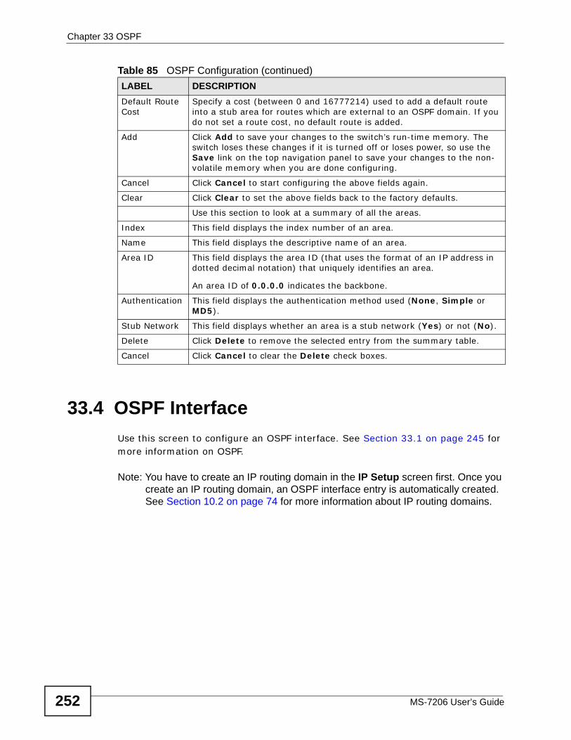
Chapter 33 OSPF
MS-7206 User’s Guide252
33.4 OSPF Interface Use this screen to configure an OSPF interface. See Section 33.1 on page 245 for more information on OSPF.
Note: You have to create an IP routing domain in the IP Setup screen first. Once you create an IP routing domain, an OSPF interface entry is automatically created. See Section 10.2 on page 74 for more information about IP routing domains.
Default Route Cost
Specify a cost (between 0 and 16777214) used to add a default route into a stub area for routes which are external to an OSPF domain. If you do not set a route cost, no default route is added.
Add Click Add to save your changes to the switch’s run-time memory. The switch loses these changes if it is turned off or loses power, so use the Save link on the top navigation panel to save your changes to the non-volatile memory when you are done configuring.
Cancel Click Cancel to start configuring the above fields again.
Clear Click Clear to set the above fields back to the factory defaults.
Use this section to look at a summary of all the areas.
Index This field displays the index number of an area.
Name This field displays the descriptive name of an area.
Area ID This field displays the area ID (that uses the format of an IP address in dotted decimal notation) that uniquely identifies an area.
An area ID of 0.0.0.0 indicates the backbone.
Authentication This field displays the authentication method used (None, Simple or MD5).
Stub Network This field displays whether an area is a stub network (Yes) or not (No).
Delete Click Delete to remove the selected entry from the summary table.
Cancel Click Cancel to clear the Delete check boxes.
Table 85 OSPF Configuration (continued)LABEL DESCRIPTION
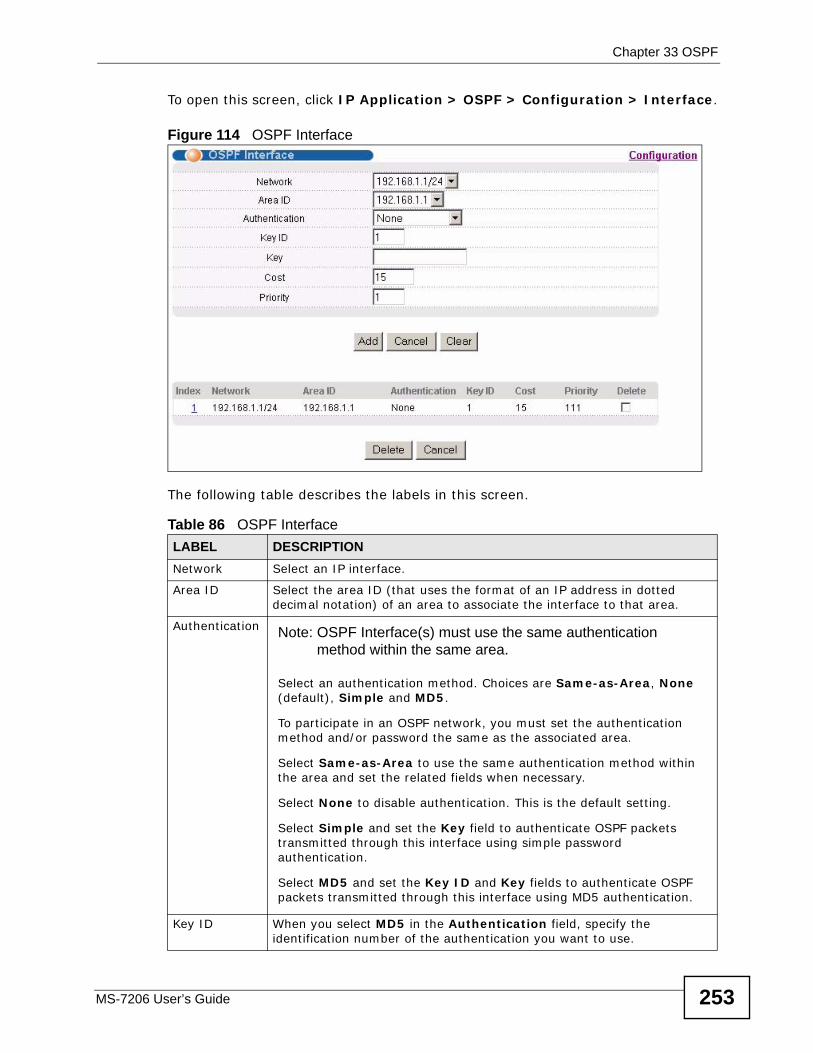
Chapter 33 OSPF
MS-7206 User’s Guide 253
To open this screen, click IP Application > OSPF > Configuration > Interface.
Figure 114 OSPF Interface
The following table describes the labels in this screen.
Table 86 OSPF InterfaceLABEL DESCRIPTIONNetwork Select an IP interface.
Area ID Select the area ID (that uses the format of an IP address in dotted decimal notation) of an area to associate the interface to that area.
Authentication Note: OSPF Interface(s) must use the same authentication method within the same area.
Select an authentication method. Choices are Same-as-Area, None (default), Simple and MD5.
To participate in an OSPF network, you must set the authentication method and/or password the same as the associated area.
Select Same-as-Area to use the same authentication method within the area and set the related fields when necessary.
Select None to disable authentication. This is the default setting.
Select Simple and set the Key field to authenticate OSPF packets transmitted through this interface using simple password authentication.
Select MD5 and set the Key ID and Key fields to authenticate OSPF packets transmitted through this interface using MD5 authentication.
Key ID When you select MD5 in the Authentication field, specify the identification number of the authentication you want to use.
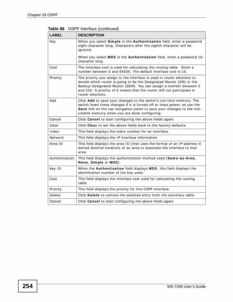
Chapter 33 OSPF
MS-7206 User’s Guide254
Key When you select Simple in the Authentication field, enter a password eight-character long. Characters after the eighth character will be ignored.
When you select MD5 in the Authentication field, enter a password 16-character long.
Cost The interface cost is used for calculating the routing table. Enter a number between 0 and 65535. The default interface cost is 15.
Priority The priority you assign to the interface is used in router elections to decide which router is going to be the Designated Router (DR) or the Backup Designated Router (BDR). You can assign a number between 0 and 255. A priority of 0 means that the router will not participate in router elections.
Add Click Add to save your changes to the switch’s run-time memory. The switch loses these changes if it is turned off or loses power, so use the Save link on the top navigation panel to save your changes to the non-volatile memory when you are done configuring.
Cancel Click Cancel to start configuring the above fields again.
Clear Click Clear to set the above fields back to the factory defaults.
Index This field displays the index number for an interface.
Network This field displays the IP interface information.
Area ID This field displays the area ID (that uses the format of an IP address in dotted decimal notation) of an area to associate the interface to that area.
Authentication This field displays the authentication method used (Same-as-Area, None, Simple or MD5).
Key ID When the Authentication field displays MD5, this field displays the identification number of the key used.
Cost This field displays the interface cost used for calculating the routing table.
Priority This field displays the priority for this OSPF interface.
Delete Click Delete to remove the selected entry from the summary table.
Cancel Click Cancel to start configuring the above fields again.
Table 86 OSPF Interface (continued)LABEL DESCRIPTION
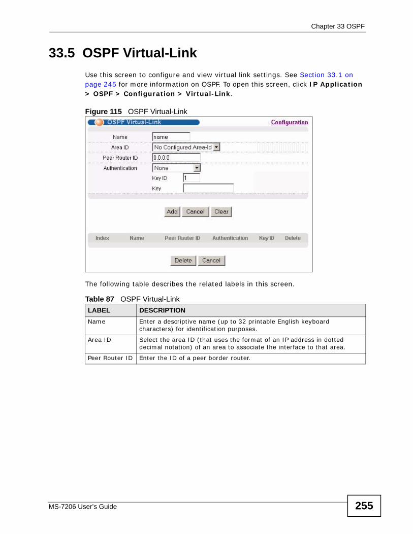
Chapter 33 OSPF
MS-7206 User’s Guide 255
33.5 OSPF Virtual-Link Use this screen to configure and view virtual link settings. See Section 33.1 on page 245 for more information on OSPF. To open this screen, click IP Application > OSPF > Configuration > Virtual-Link.
Figure 115 OSPF Virtual-Link
The following table describes the related labels in this screen.
Table 87 OSPF Virtual-LinkLABEL DESCRIPTIONName Enter a descriptive name (up to 32 printable English keyboard
characters) for identification purposes.
Area ID Select the area ID (that uses the format of an IP address in dotted decimal notation) of an area to associate the interface to that area.
Peer Router ID Enter the ID of a peer border router.
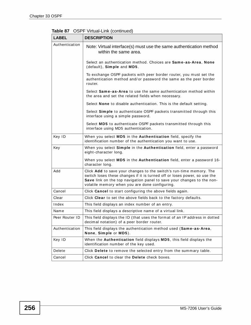
Chapter 33 OSPF
MS-7206 User’s Guide256
Authentication Note: Virtual interface(s) must use the same authentication method within the same area.
Select an authentication method. Choices are Same-as-Area, None (default), Simple and MD5.
To exchange OSPF packets with peer border router, you must set the authentication method and/or password the same as the peer border router.
Select Same-as-Area to use the same authentication method within the area and set the related fields when necessary.
Select None to disable authentication. This is the default setting.
Select Simple to authenticate OSPF packets transmitted through this interface using a simple password.
Select MD5 to authenticate OSPF packets transmitted through this interface using MD5 authentication.
Key ID When you select MD5 in the Authentication field, specify the identification number of the authentication you want to use.
Key When you select Simple in the Authentication field, enter a password eight-character long.
When you select MD5 in the Authentication field, enter a password 16-character long.
Add Click Add to save your changes to the switch’s run-time memory. The switch loses these changes if it is turned off or loses power, so use the Save link on the top navigation panel to save your changes to the non-volatile memory when you are done configuring.
Cancel Click Cancel to start configuring the above fields again.
Clear Click Clear to set the above fields back to the factory defaults.
Index This field displays an index number of an entry.
Name This field displays a descriptive name of a virtual link.
Peer Router ID This field displays the ID (that uses the format of an IP address in dotted decimal notation) of a peer border router.
Authentication This field displays the authentication method used (Same-as-Area, None, Simple or MD5).
Key ID When the Authentication field displays MD5, this field displays the identification number of the key used.
Delete Click Delete to remove the selected entry from the summary table.
Cancel Click Cancel to clear the Delete check boxes.
Table 87 OSPF Virtual-Link (continued)LABEL DESCRIPTION
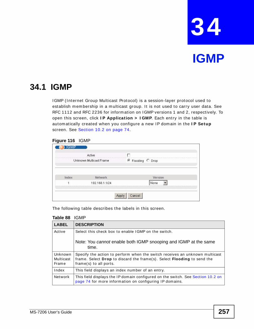
MS-7206 User’s Guide 257
CHAPTER 34 IGMP
34.1 IGMPIGMP (Internet Group Multicast Protocol) is a session-layer protocol used to establish membership in a multicast group. It is not used to carry user data. See RFC 1112 and RFC 2236 for information on IGMP versions 1 and 2, respectively. To open this screen, click IP Application > IGMP. Each entry in the table is automatically created when you configure a new IP domain in the IP Setup screen. See Section 10.2 on page 74.
Figure 116 IGMP
The following table describes the labels in this screen.
Table 88 IGMPLABEL DESCRIPTIONActive Select this check box to enable IGMP on the switch.
Note: You cannot enable both IGMP snooping and IGMP at the same time.
Unknown Multicast Frame
Specify the action to perform when the switch receives an unknown multicast frame. Select Drop to discard the frame(s). Select Flooding to send the frame(s) to all ports.
Index This field displays an index number of an entry.
Network This field displays the IP domain configured on the switch. See Section 10.2 on page 74 for more information on configuring IP domains.
Chapter 34 IGMP
MS-7206 User’s Guide258
Version Select an IGMP version from the drop-down list box. Choices are IGMP-v1, IGMP-v2, IGMP-v3 and None.
The switch supports both IGMP version 1 (IGMP-v1), version 2 (IGMP-v2) and version 3 (IGMP-v3). At start up, the switch queries all directly connected networks to gather group membership. After that, the switch periodically updates this information.
Apply Click Apply to save your changes to the switch’s run-time memory. The switch loses these changes if it is turned off or loses power, so use the Save link on the top navigation panel to save your changes to the non-volatile memory when you are done configuring.
Cancel Click Cancel to begin configuring the fields again.
Table 88 IGMP (continued)LABEL DESCRIPTION
MS-7206 User’s Guide 259
CHAPTER 35 DVMRP
This chapter introduces DVMRP and tells you how to configure it.
35.1 DVMRP OverviewDVMRP (Distance Vector Multicast Routing Protocol) is a protocol used for routing multicast data within an autonomous system (AS). This DVMRP implementation is based on draft-ietf-idmr-dvmrp-v3-10. DVMRP provides multicast forwarding capability to a layer 3 switch that runs both the IPv4 protocol (with IP Multicast support) and the IGMP protocol. The DVMRP metric is a hop count of 32.
IGMP is a protocol used for joining or leaving a multicast group. You must have IGMP enabled when you enable DVMRP; otherwise you see the screen as in Figure 119 on page 261.
35.2 How DVMRP WorksDVMRP uses the Reverse Path Multicasting (RPM) algorithm to generate an IP Multicast delivery tree. Multicast packets are forwarded along these multicast tree branches. DVMRP dynamically learns host membership information using Internet Group Multicast Protocol (IGMP). The trees are updated dynamically to track the membership of individual groups.
1 Initially an advertisement multicast packet is broadcast (“B” in the following figure).
2 DVMRP-enabled Layer 3 devices that do not have any hosts in their networks that belong to this multicast group send back a prune message (“P”).
3 If hosts later join the multicast group, a graft message (“G”) to undo the prune is sent to the parent.
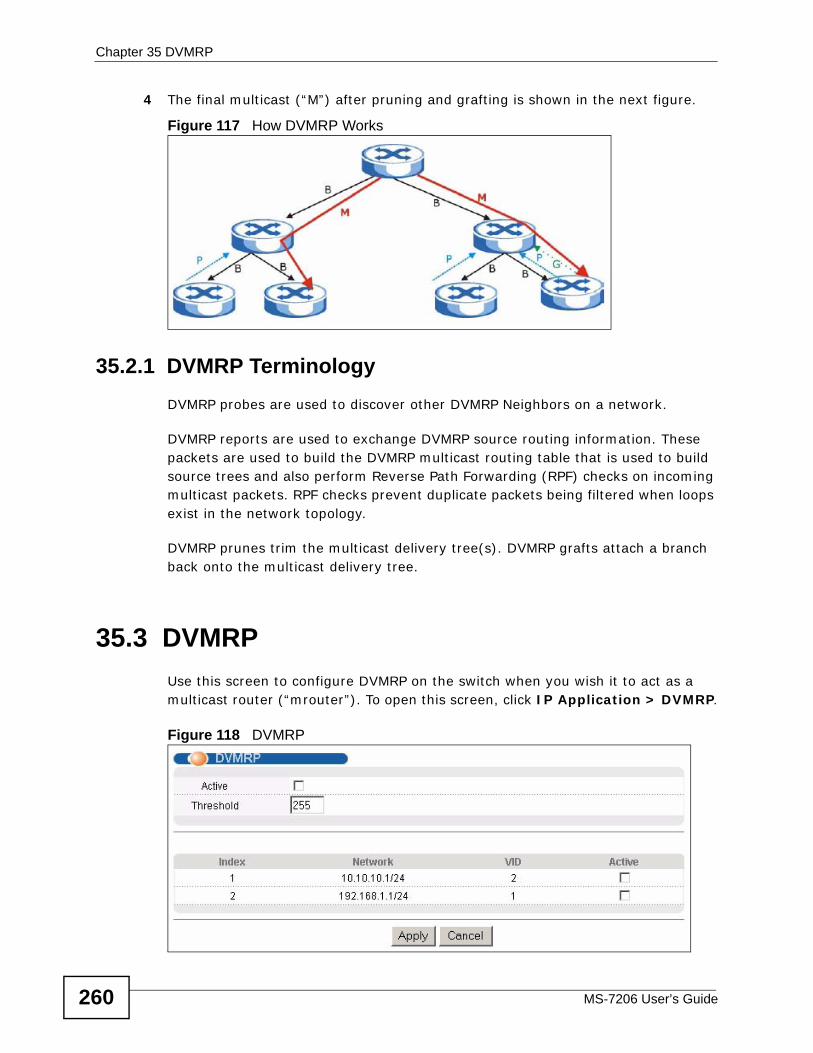
Chapter 35 DVMRP
MS-7206 User’s Guide260
4 The final multicast (“M”) after pruning and grafting is shown in the next figure.
Figure 117 How DVMRP Works
35.2.1 DVMRP Terminology DVMRP probes are used to discover other DVMRP Neighbors on a network.
DVMRP reports are used to exchange DVMRP source routing information. These packets are used to build the DVMRP multicast routing table that is used to build source trees and also perform Reverse Path Forwarding (RPF) checks on incoming multicast packets. RPF checks prevent duplicate packets being filtered when loops exist in the network topology.
DVMRP prunes trim the multicast delivery tree(s). DVMRP grafts attach a branch back onto the multicast delivery tree.
35.3 DVMRPUse this screen to configure DVMRP on the switch when you wish it to act as a multicast router (“mrouter”). To open this screen, click IP Application > DVMRP.
Figure 118 DVMRP
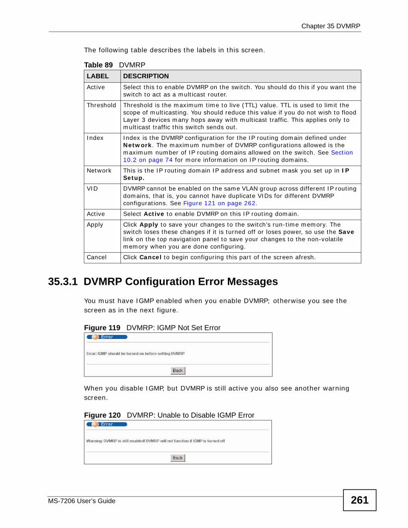
Chapter 35 DVMRP
MS-7206 User’s Guide 261
The following table describes the labels in this screen.
35.3.1 DVMRP Configuration Error Messages You must have IGMP enabled when you enable DVMRP; otherwise you see the screen as in the next figure.
Figure 119 DVMRP: IGMP Not Set Error
When you disable IGMP, but DVMRP is still active you also see another warning screen.
Figure 120 DVMRP: Unable to Disable IGMP Error
Table 89 DVMRPLABEL DESCRIPTIONActive Select this to enable DVMRP on the switch. You should do this if you want the
switch to act as a multicast router.
Threshold Threshold is the maximum time to live (TTL) value. TTL is used to limit the scope of multicasting. You should reduce this value if you do not wish to flood Layer 3 devices many hops away with multicast traffic. This applies only to multicast traffic this switch sends out.
Index Index is the DVMRP configuration for the IP routing domain defined under Network. The maximum number of DVMRP configurations allowed is the maximum number of IP routing domains allowed on the switch. See Section 10.2 on page 74 for more information on IP routing domains.
Network This is the IP routing domain IP address and subnet mask you set up in IP Setup.
VID DVMRP cannot be enabled on the same VLAN group across different IP routing domains, that is, you cannot have duplicate VIDs for different DVMRP configurations. See Figure 121 on page 262.
Active Select Active to enable DVMRP on this IP routing domain.
Apply Click Apply to save your changes to the switch’s run-time memory. The switch loses these changes if it is turned off or loses power, so use the Save link on the top navigation panel to save your changes to the non-volatile memory when you are done configuring.
Cancel Click Cancel to begin configuring this part of the screen afresh.
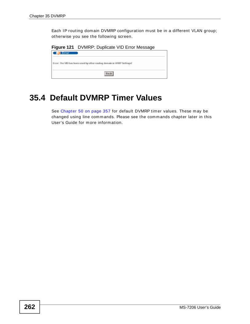
Chapter 35 DVMRP
MS-7206 User’s Guide262
Each IP routing domain DVMRP configuration must be in a different VLAN group; otherwise you see the following screen.
Figure 121 DVMRP: Duplicate VID Error Message
35.4 Default DVMRP Timer Values See Chapter 50 on page 357 for default DVMRP timer values. These may be changed using line commands. Please see the commands chapter later in this User's Guide for more information.
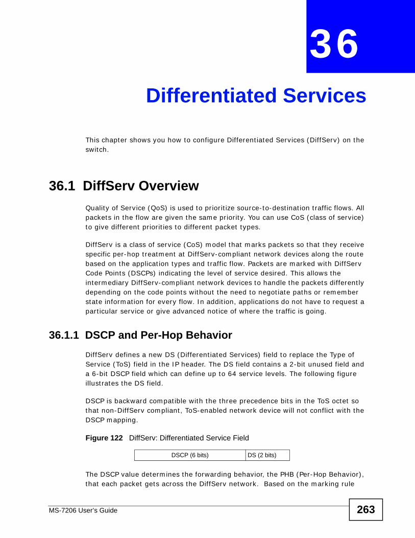
MS-7206 User’s Guide 263
CHAPTER 36 Differentiated Services
This chapter shows you how to configure Differentiated Services (DiffServ) on the switch.
36.1 DiffServ Overview Quality of Service (QoS) is used to prioritize source-to-destination traffic flows. All packets in the flow are given the same priority. You can use CoS (class of service) to give different priorities to different packet types.
DiffServ is a class of service (CoS) model that marks packets so that they receive specific per-hop treatment at DiffServ-compliant network devices along the route based on the application types and traffic flow. Packets are marked with DiffServ Code Points (DSCPs) indicating the level of service desired. This allows the intermediary DiffServ-compliant network devices to handle the packets differently depending on the code points without the need to negotiate paths or remember state information for every flow. In addition, applications do not have to request a particular service or give advanced notice of where the traffic is going.
36.1.1 DSCP and Per-Hop Behavior DiffServ defines a new DS (Differentiated Services) field to replace the Type of Service (ToS) field in the IP header. The DS field contains a 2-bit unused field and a 6-bit DSCP field which can define up to 64 service levels. The following figure illustrates the DS field.
DSCP is backward compatible with the three precedence bits in the ToS octet so that non-DiffServ compliant, ToS-enabled network device will not conflict with the DSCP mapping.
Figure 122 DiffServ: Differentiated Service Field
The DSCP value determines the forwarding behavior, the PHB (Per-Hop Behavior), that each packet gets across the DiffServ network. Based on the marking rule
DSCP (6 bits) DS (2 bits)
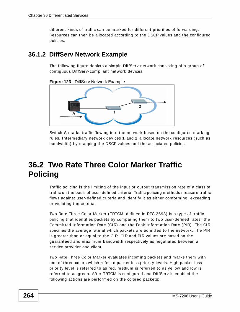
Chapter 36 Differentiated Services
MS-7206 User’s Guide264
different kinds of traffic can be marked for different priorities of forwarding. Resources can then be allocated according to the DSCP values and the configured policies.
36.1.2 DiffServ Network Example The following figure depicts a simple DiffServ network consisting of a group of contiguous DiffServ-compliant network devices.
Figure 123 DiffServ Network Example
Switch A marks traffic flowing into the network based on the configured marking rules. Intermediary network devices 1 and 2 allocate network resources (such as bandwidth) by mapping the DSCP values and the associated policies.
36.2 Two Rate Three Color Marker Traffic Policing
Traffic policing is the limiting of the input or output transmission rate of a class of traffic on the basis of user-defined criteria. Traffic policing methods measure traffic flows against user-defined criteria and identify it as either conforming, exceeding or violating the criteria.
Two Rate Three Color Marker (TRTCM, defined in RFC 2698) is a type of traffic policing that identifies packets by comparing them to two user-defined rates: the Committed Information Rate (CIR) and the Peak Information Rate (PIR). The CIR specifies the average rate at which packets are admitted to the network. The PIR is greater than or equal to the CIR. CIR and PIR values are based on the guaranteed and maximum bandwidth respectively as negotiated between a service provider and client.
Two Rate Three Color Marker evaluates incoming packets and marks them with one of three colors which refer to packet loss priority levels. High packet loss priority level is referred to as red, medium is referred to as yellow and low is referred to as green. After TRTCM is configured and DiffServ is enabled the following actions are performed on the colored packets:
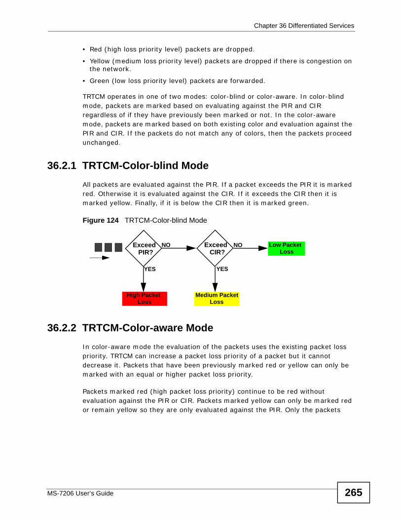
Chapter 36 Differentiated Services
MS-7206 User’s Guide 265
• Red (high loss priority level) packets are dropped.
• Yellow (medium loss priority level) packets are dropped if there is congestion on the network.
• Green (low loss priority level) packets are forwarded.
TRTCM operates in one of two modes: color-blind or color-aware. In color-blind mode, packets are marked based on evaluating against the PIR and CIR regardless of if they have previously been marked or not. In the color-aware mode, packets are marked based on both existing color and evaluation against the PIR and CIR. If the packets do not match any of colors, then the packets proceed unchanged.
36.2.1 TRTCM-Color-blind ModeAll packets are evaluated against the PIR. If a packet exceeds the PIR it is marked red. Otherwise it is evaluated against the CIR. If it exceeds the CIR then it is marked yellow. Finally, if it is below the CIR then it is marked green.
Figure 124 TRTCM-Color-blind Mode
36.2.2 TRTCM-Color-aware ModeIn color-aware mode the evaluation of the packets uses the existing packet loss priority. TRTCM can increase a packet loss priority of a packet but it cannot decrease it. Packets that have been previously marked red or yellow can only be marked with an equal or higher packet loss priority.
Packets marked red (high packet loss priority) continue to be red without evaluation against the PIR or CIR. Packets marked yellow can only be marked red or remain yellow so they are only evaluated against the PIR. Only the packets
Exceed PIR?
High Packet Loss
Exceed CIR?
Medium Packet Loss
NO
YES
NO
YES
Low Packet Loss
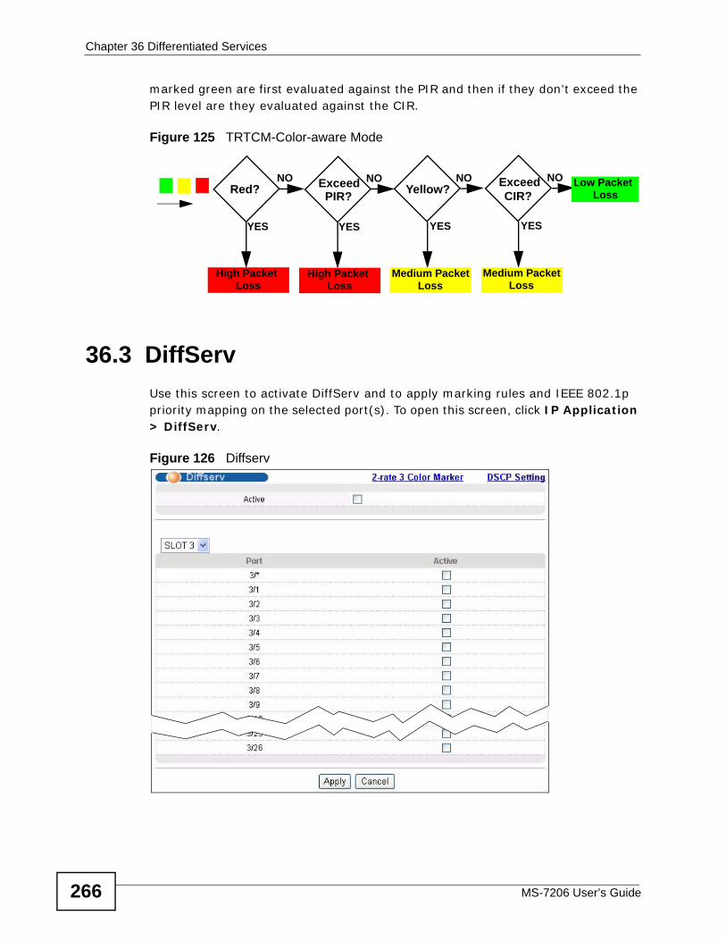
Chapter 36 Differentiated Services
MS-7206 User’s Guide266
marked green are first evaluated against the PIR and then if they don’t exceed the PIR level are they evaluated against the CIR.
Figure 125 TRTCM-Color-aware Mode
36.3 DiffServUse this screen to activate DiffServ and to apply marking rules and IEEE 802.1p priority mapping on the selected port(s). To open this screen, click IP Application > DiffServ.
Figure 126 Diffserv
Exceed PIR?
High Packet Loss
Exceed CIR?
Medium Packet Loss
NO
YES
NO
YES
Low Packet Loss
High Packet Loss
NO
YES
Red? Yellow?
Medium Packet Loss
NO
YES
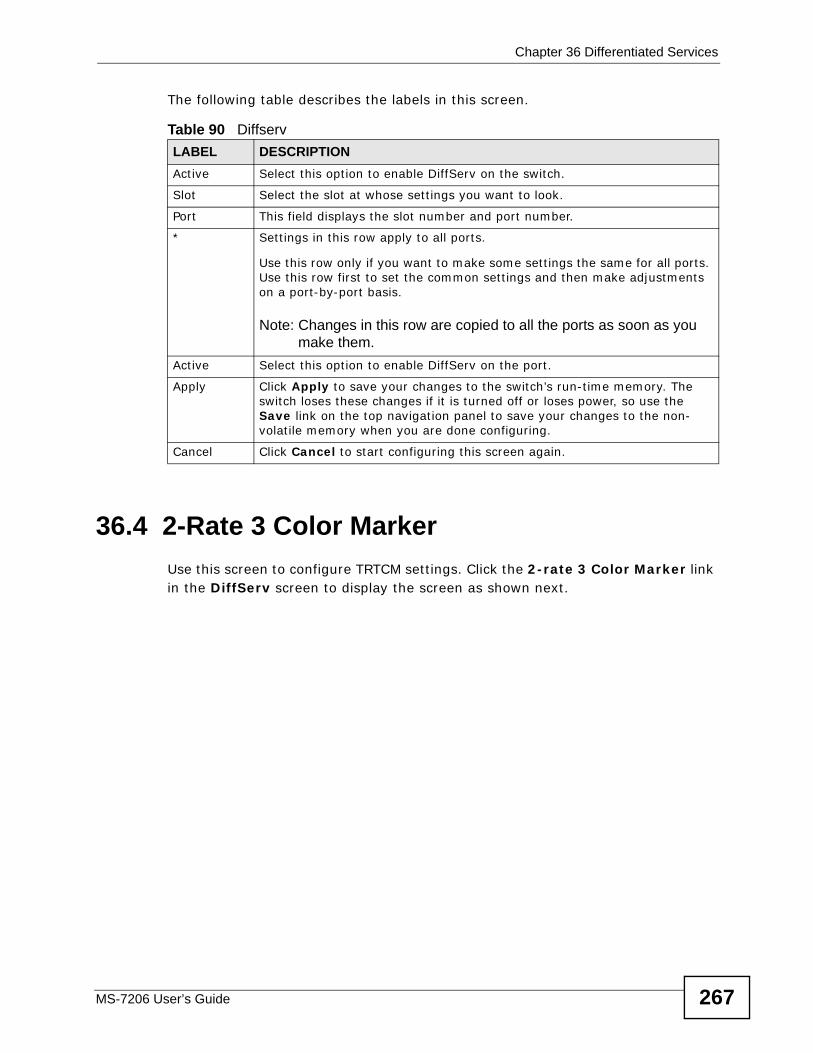
Chapter 36 Differentiated Services
MS-7206 User’s Guide 267
The following table describes the labels in this screen.
36.4 2-Rate 3 Color Marker Use this screen to configure TRTCM settings. Click the 2-rate 3 Color Marker link in the DiffServ screen to display the screen as shown next.
Table 90 Diffserv LABEL DESCRIPTIONActive Select this option to enable DiffServ on the switch.
Slot Select the slot at whose settings you want to look.
Port This field displays the slot number and port number.
* Settings in this row apply to all ports.
Use this row only if you want to make some settings the same for all ports. Use this row first to set the common settings and then make adjustments on a port-by-port basis.
Note: Changes in this row are copied to all the ports as soon as you make them.
Active Select this option to enable DiffServ on the port.
Apply Click Apply to save your changes to the switch’s run-time memory. The switch loses these changes if it is turned off or loses power, so use the Save link on the top navigation panel to save your changes to the non-volatile memory when you are done configuring.
Cancel Click Cancel to start configuring this screen again.
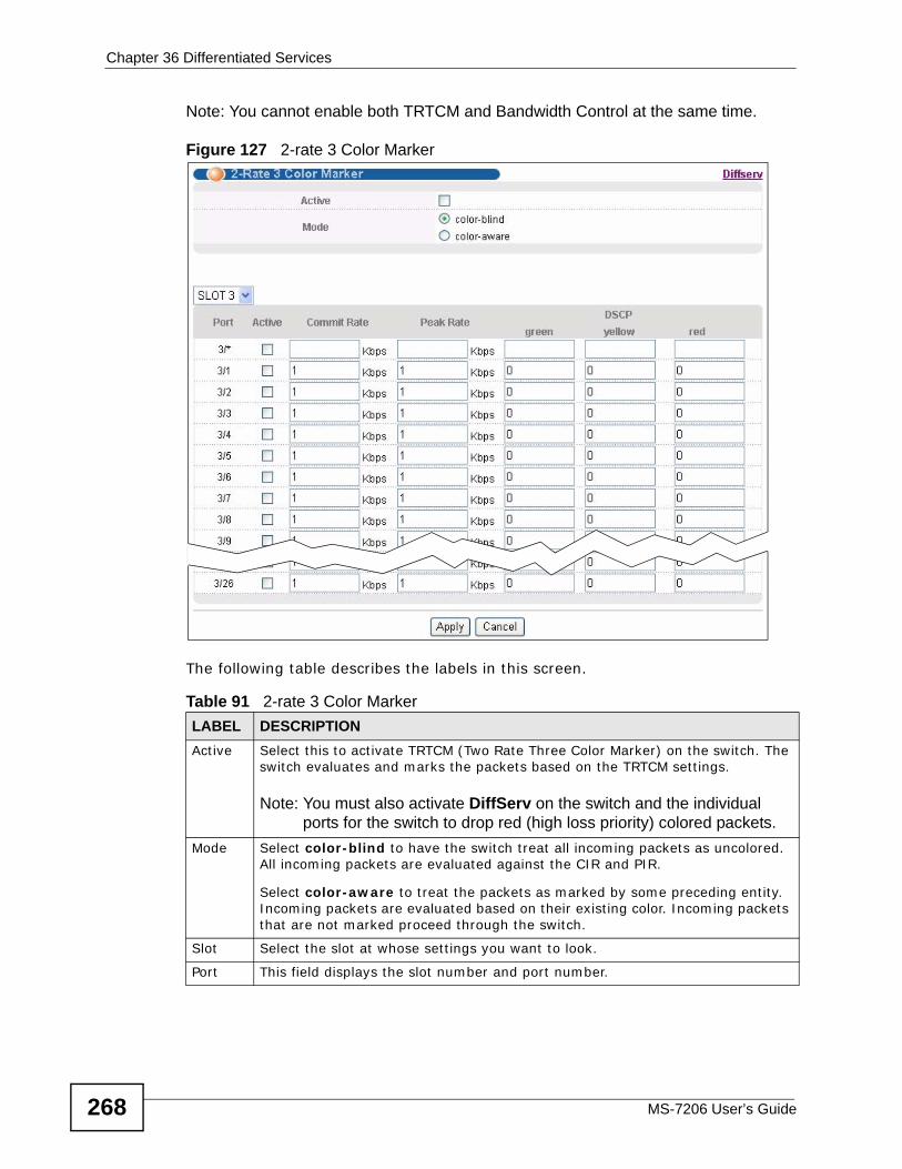
Chapter 36 Differentiated Services
MS-7206 User’s Guide268
Note: You cannot enable both TRTCM and Bandwidth Control at the same time.
Figure 127 2-rate 3 Color Marker
The following table describes the labels in this screen.
Table 91 2-rate 3 Color Marker LABEL DESCRIPTIONActive Select this to activate TRTCM (Two Rate Three Color Marker) on the switch. The
switch evaluates and marks the packets based on the TRTCM settings.
Note: You must also activate DiffServ on the switch and the individual ports for the switch to drop red (high loss priority) colored packets.
Mode Select color-blind to have the switch treat all incoming packets as uncolored. All incoming packets are evaluated against the CIR and PIR.
Select color-aware to treat the packets as marked by some preceding entity. Incoming packets are evaluated based on their existing color. Incoming packets that are not marked proceed through the switch.
Slot Select the slot at whose settings you want to look.
Port This field displays the slot number and port number.
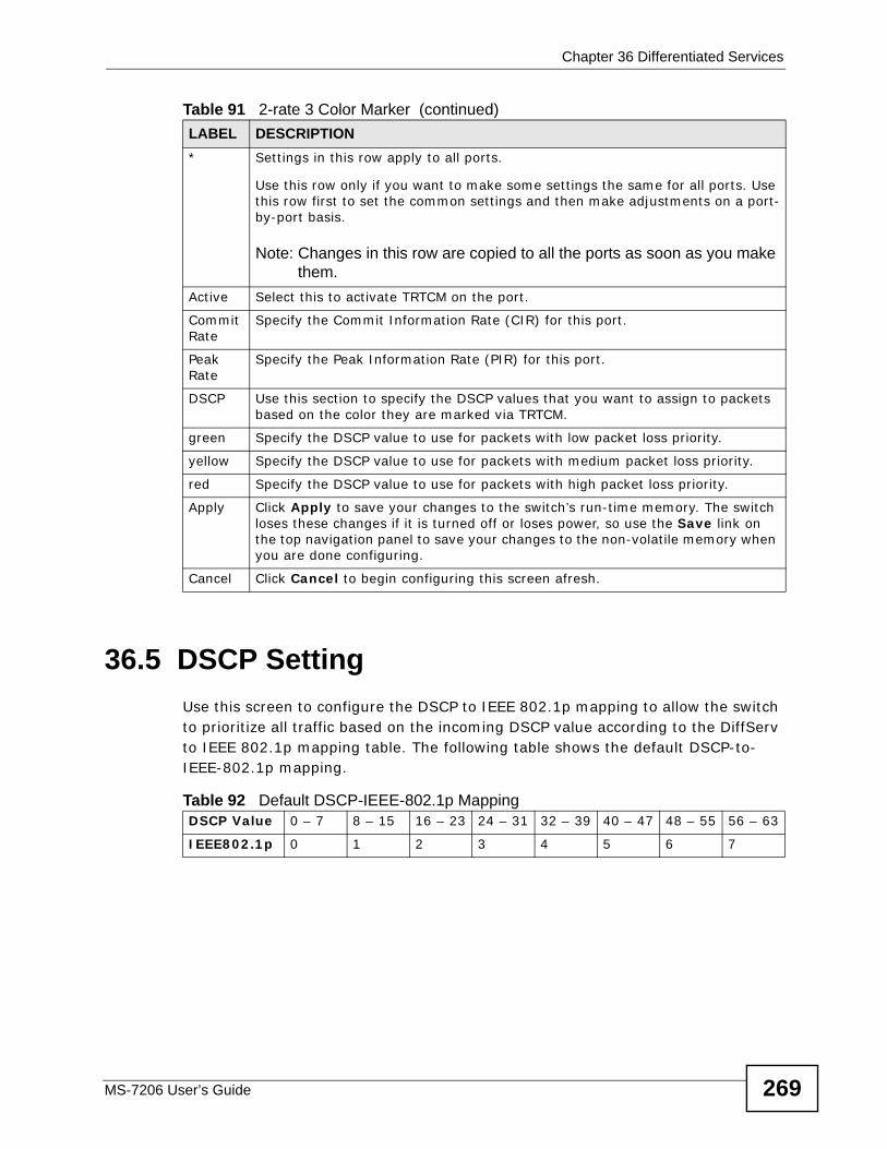
Chapter 36 Differentiated Services
MS-7206 User’s Guide 269
36.5 DSCP Setting Use this screen to configure the DSCP to IEEE 802.1p mapping to allow the switch to prioritize all traffic based on the incoming DSCP value according to the DiffServ to IEEE 802.1p mapping table. The following table shows the default DSCP-to-IEEE-802.1p mapping.
* Settings in this row apply to all ports.
Use this row only if you want to make some settings the same for all ports. Use this row first to set the common settings and then make adjustments on a port-by-port basis.
Note: Changes in this row are copied to all the ports as soon as you make them.
Active Select this to activate TRTCM on the port.
Commit Rate
Specify the Commit Information Rate (CIR) for this port.
Peak Rate
Specify the Peak Information Rate (PIR) for this port.
DSCP Use this section to specify the DSCP values that you want to assign to packets based on the color they are marked via TRTCM.
green Specify the DSCP value to use for packets with low packet loss priority.
yellow Specify the DSCP value to use for packets with medium packet loss priority.
red Specify the DSCP value to use for packets with high packet loss priority.
Apply Click Apply to save your changes to the switch’s run-time memory. The switch loses these changes if it is turned off or loses power, so use the Save link on the top navigation panel to save your changes to the non-volatile memory when you are done configuring.
Cancel Click Cancel to begin configuring this screen afresh.
Table 91 2-rate 3 Color Marker (continued)LABEL DESCRIPTION
Table 92 Default DSCP-IEEE-802.1p MappingDSCP Value 0 – 7 8 – 15 16 – 23 24 – 31 32 – 39 40 – 47 48 – 55 56 – 63
IEEE802.1p 0 1 2 3 4 5 6 7
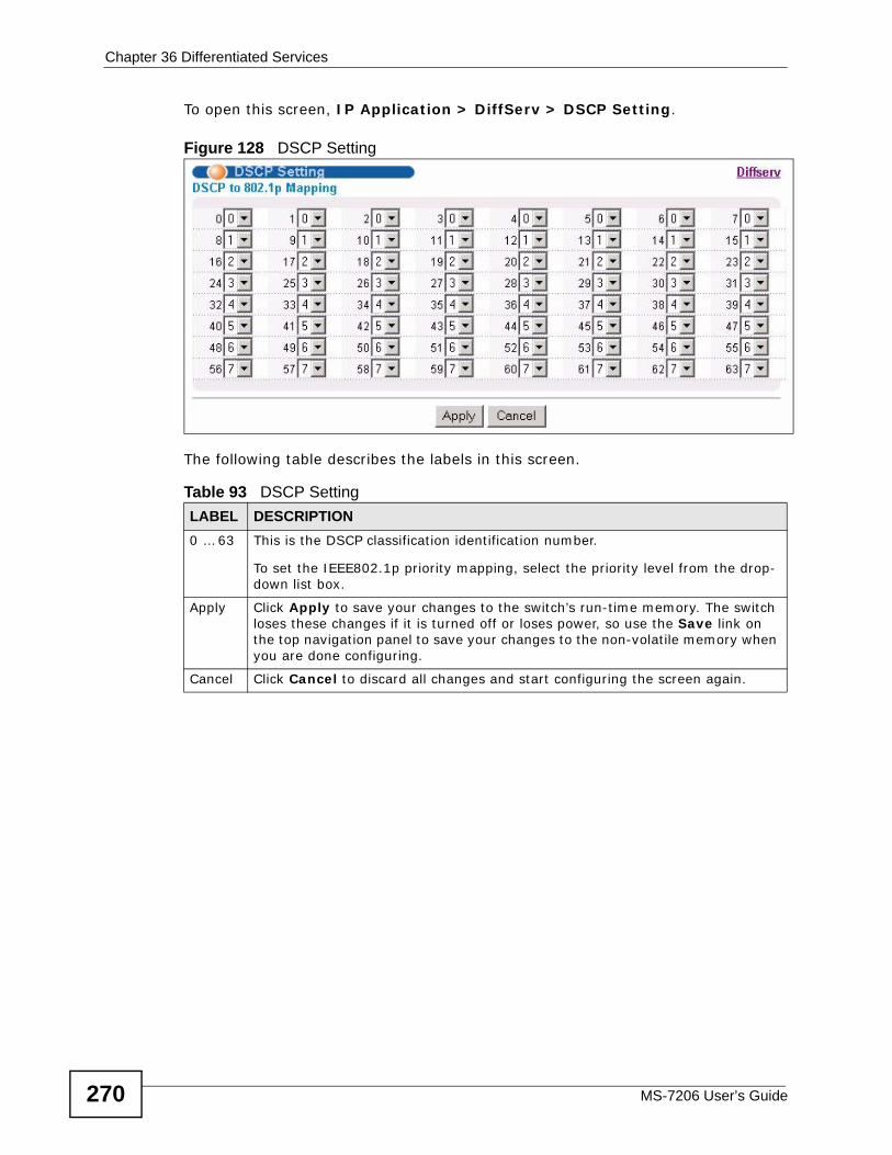
Chapter 36 Differentiated Services
MS-7206 User’s Guide270
To open this screen, IP Application > DiffServ > DSCP Setting.
Figure 128 DSCP Setting
The following table describes the labels in this screen.
Table 93 DSCP SettingLABEL DESCRIPTION0 … 63 This is the DSCP classification identification number.
To set the IEEE802.1p priority mapping, select the priority level from the drop-down list box.
Apply Click Apply to save your changes to the switch’s run-time memory. The switch loses these changes if it is turned off or loses power, so use the Save link on the top navigation panel to save your changes to the non-volatile memory when you are done configuring.
Cancel Click Cancel to discard all changes and start configuring the screen again.
MS-7206 User’s Guide 271
CHAPTER 37 DHCP
This chapter shows you how to configure the DHCP feature.
37.1 DHCP Overview DHCP (Dynamic Host Configuration Protocol RFC 2131 and RFC 2132) allows individual computers to obtain TCP/IP configuration at start-up from a server. You can configure the switch as a DHCP server or disable it. When configured as a server, the switch provides the TCP/IP configuration for the clients. If you disable the DHCP service, you must have another DHCP server on your LAN, or else the computer must be manually configured.
37.1.1 DHCP modes The switch can be configured as a DHCP server or DHCP relay agent.
• If you configure the switch as a DHCP server, it will maintain the pool of addresses and distribute them to your LAN computers.
• If there is an Ethernet device that performs the DHCP server function for your network, then you can configure the switch as a DHCP relay agent. When the switch receives a request from a computer on your network, it contacts the Ethernet device (the DHCP server) for the necessary IP information, and then relays the assigned information back to the computer.
37.1.2 DHCP Configuration OptionsThe DHCP configuration on the switch is divided into Global and VLAN screens. The screen you should use for configuration depends on the DHCP services you want to offer the DHCP clients on your network. Choose the configuration screen based on the following criteria:
• Global - The switch forwards all DHCP requests to the same DHCP server.
• VLAN - The switch is configured on a VLAN by VLAN basis. The switch can be configured as a DHCP server or to relay DHCP requests to different DHCP servers for clients in different VLAN.
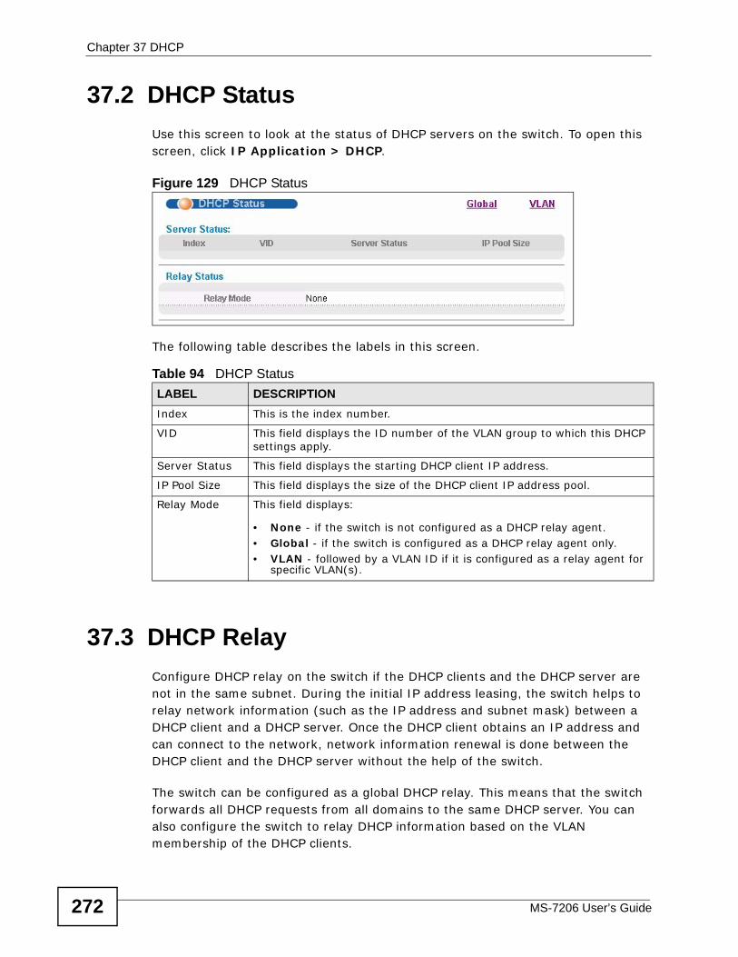
Chapter 37 DHCP
MS-7206 User’s Guide272
37.2 DHCP StatusUse this screen to look at the status of DHCP servers on the switch. To open this screen, click IP Application > DHCP.
Figure 129 DHCP Status
The following table describes the labels in this screen.
37.3 DHCP RelayConfigure DHCP relay on the switch if the DHCP clients and the DHCP server are not in the same subnet. During the initial IP address leasing, the switch helps to relay network information (such as the IP address and subnet mask) between a DHCP client and a DHCP server. Once the DHCP client obtains an IP address and can connect to the network, network information renewal is done between the DHCP client and the DHCP server without the help of the switch.
The switch can be configured as a global DHCP relay. This means that the switch forwards all DHCP requests from all domains to the same DHCP server. You can also configure the switch to relay DHCP information based on the VLAN membership of the DHCP clients.
Table 94 DHCP StatusLABEL DESCRIPTIONIndex This is the index number.
VID This field displays the ID number of the VLAN group to which this DHCP settings apply.
Server Status This field displays the starting DHCP client IP address.
IP Pool Size This field displays the size of the DHCP client IP address pool.
Relay Mode This field displays:
• None - if the switch is not configured as a DHCP relay agent.• Global - if the switch is configured as a DHCP relay agent only.• VLAN - followed by a VLAN ID if it is configured as a relay agent for
specific VLAN(s).
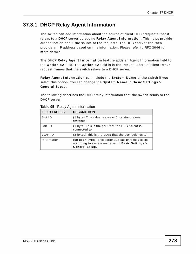
Chapter 37 DHCP
MS-7206 User’s Guide 273
37.3.1 DHCP Relay Agent InformationThe switch can add information about the source of client DHCP requests that it relays to a DHCP server by adding Relay Agent Information. This helps provide authentication about the source of the requests. The DHCP server can then provide an IP address based on this information. Please refer to RFC 3046 for more details.
The DHCP Relay Agent Information feature adds an Agent Information field to the Option 82 field. The Option 82 field is in the DHCP headers of client DHCP request frames that the switch relays to a DHCP server.
Relay Agent Information can include the System Name of the switch if you select this option. You can change the System Name in Basic Settings > General Setup.
The following describes the DHCP relay information that the switch sends to the DHCP server:
Table 95 Relay Agent InformationFIELD LABELS DESCRIPTIONSlot ID (1 byte) This value is always 0 for stand-alone
switches.
Port ID (1 byte) This is the port that the DHCP client is connected to.
VLAN ID (2 bytes) This is the VLAN that the port belongs to.
Information (up to 64 bytes) This optional, read-only field is set according to system name set in Basic Settings > General Setup.
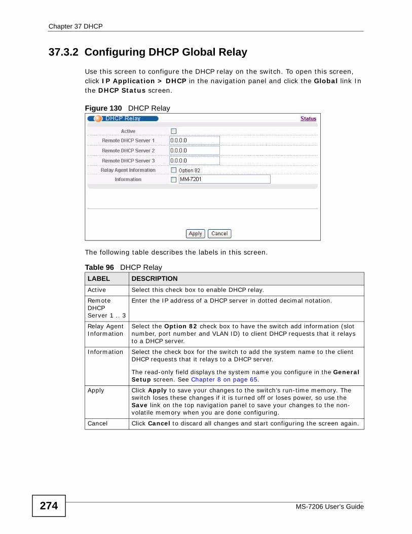
Chapter 37 DHCP
MS-7206 User’s Guide274
37.3.2 Configuring DHCP Global RelayUse this screen to configure the DHCP relay on the switch. To open this screen, click IP Application > DHCP in the navigation panel and click the Global link In the DHCP Status screen.
Figure 130 DHCP Relay
The following table describes the labels in this screen.
Table 96 DHCP RelayLABEL DESCRIPTIONActive Select this check box to enable DHCP relay.
Remote DHCP Server 1 .. 3
Enter the IP address of a DHCP server in dotted decimal notation.
Relay Agent Information
Select the Option 82 check box to have the switch add information (slot number, port number and VLAN ID) to client DHCP requests that it relays to a DHCP server.
Information Select the check box for the switch to add the system name to the client DHCP requests that it relays to a DHCP server.
The read-only field displays the system name you configure in the General Setup screen. See Chapter 8 on page 65.
Apply Click Apply to save your changes to the switch’s run-time memory. The switch loses these changes if it is turned off or loses power, so use the Save link on the top navigation panel to save your changes to the non-volatile memory when you are done configuring.
Cancel Click Cancel to discard all changes and start configuring the screen again.
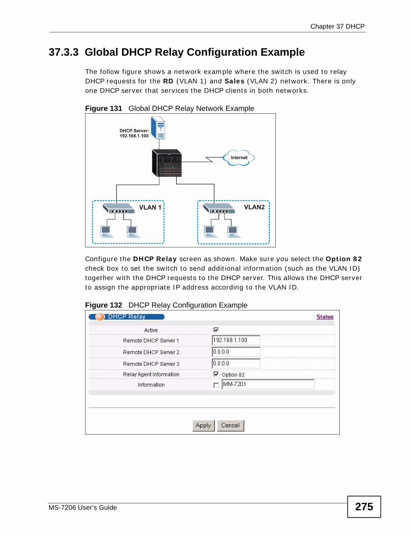
Chapter 37 DHCP
MS-7206 User’s Guide 275
37.3.3 Global DHCP Relay Configuration ExampleThe follow figure shows a network example where the switch is used to relay DHCP requests for the RD (VLAN 1) and Sales (VLAN 2) network. There is only one DHCP server that services the DHCP clients in both networks.
Figure 131 Global DHCP Relay Network Example
Configure the DHCP Relay screen as shown. Make sure you select the Option 82 check box to set the switch to send additional information (such as the VLAN ID) together with the DHCP requests to the DHCP server. This allows the DHCP server to assign the appropriate IP address according to the VLAN ID.
Figure 132 DHCP Relay Configuration Example
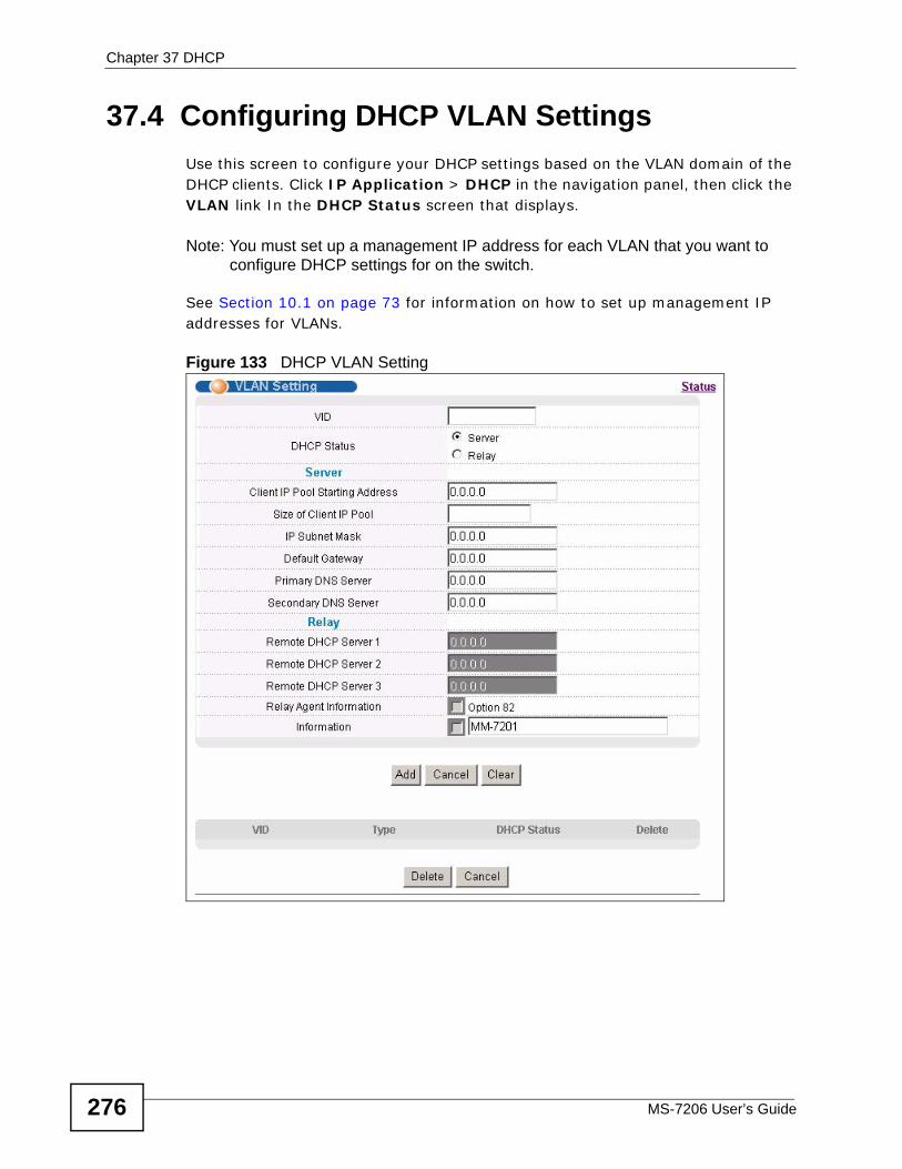
Chapter 37 DHCP
MS-7206 User’s Guide276
37.4 Configuring DHCP VLAN Settings Use this screen to configure your DHCP settings based on the VLAN domain of the DHCP clients. Click IP Application > DHCP in the navigation panel, then click the VLAN link In the DHCP Status screen that displays.
Note: You must set up a management IP address for each VLAN that you want to configure DHCP settings for on the switch.
See Section 10.1 on page 73 for information on how to set up management IP addresses for VLANs.
Figure 133 DHCP VLAN Setting

Chapter 37 DHCP
MS-7206 User’s Guide 277
The following table describes the labels in this screen.
Table 97 DHCP VLAN SettingLABEL DESCRIPTIONVID Enter the ID number of the VLAN group to which this DHCP settings apply.
DHCP Status Select Sever to set the switch to act as a DHCP server.
Select Relay to set the switch to act as a DHCP relay.
Then set the corresponding fields below.
Server
The fields are editable when you select Server in the DHCP Status field.
Client IP Pool Starting Address
Specify the first of the contiguous addresses in the IP address pool.
Size of Client IP Pool
Specify the size, or count of the IP address pool.
IP Subnet Mask
Enter the subnet mask for the client IP pool.
Default Gateway
Enter the IP address of the default gateway.
Primary/ Secondary DNS Server
Enter the IP addresses of the DNS servers. The DNS servers are passed to the DHCP clients along with the IP address and the subnet mask.
Relay
The fields are editable when you select Relay in the DHCP Status field.
Remote DHCP Server 1.. 3
Enter the IP address(es) of the DHCP server(s).
Relay Agent Information
Select the Option 82 check box to have the switch add information (slot number, port number and VLAN ID) to client DHCP requests that it relays to a DHCP server.
Information Select the check box for the switch to add the system name to the client DHCP requests that it relays to a DHCP server.
The read-only field displays the system name you configure in the General Setup screen. See Chapter 8 on page 65.
Add Click Add to save your changes to the switch’s run-time memory. The switch loses these changes if it is turned off or loses power, so use the Save link on the top navigation panel to save your changes to the non-volatile memory when you are done configuring.
Cancel Click Cancel to reset the fields to your previous configurations.
Clear Click Clear to reset the fields back to the factory defaults.
VID This field displays the ID number of the VLAN group to which this DHCP settings apply.
Type This field displays the DHCP mode (Server or Relay).
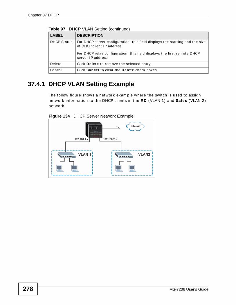
Chapter 37 DHCP
MS-7206 User’s Guide278
37.4.1 DHCP VLAN Setting ExampleThe follow figure shows a network example where the switch is used to assign network information to the DHCP clients in the RD (VLAN 1) and Sales (VLAN 2) network.
Figure 134 DHCP Server Network Example
DHCP Status For DHCP server configuration, this field displays the starting and the size of DHCP client IP address.
For DHCP relay configuration, this field displays the first remote DHCP server IP address.
Delete Click Delete to remove the selected entry.
Cancel Click Cancel to clear the Delete check boxes.
Table 97 DHCP VLAN Setting (continued)LABEL DESCRIPTION
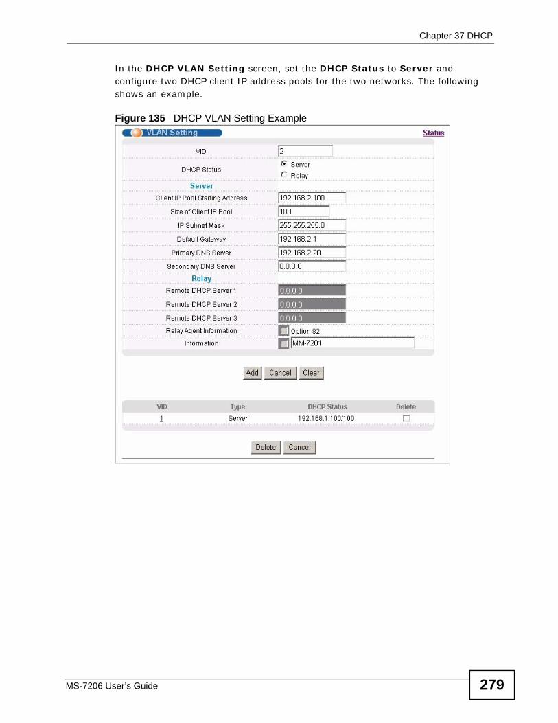
Chapter 37 DHCP
MS-7206 User’s Guide 279
In the DHCP VLAN Setting screen, set the DHCP Status to Server and configure two DHCP client IP address pools for the two networks. The following shows an example.
Figure 135 DHCP VLAN Setting Example

Chapter 37 DHCP
MS-7206 User’s Guide280
MS-7206 User’s Guide 281
CHAPTER 38 VRRP
This chapter shows you how to configure and monitor the Virtual Router Redundancy Protocol (VRRP) on the switch.
38.1 VRRP Overview Each host on a network is configured to send packets to a statically configured default gateway (this switch). The default gateway can become a single point of failure. Virtual Router Redundancy Protocol (VRRP), defined in RFC 2338, allows you to create redundant backup gateways to ensure that the default gateway of a host is always available.
In VRRP, a virtual router (VR) represents a number of physical layer-3 devices. An IP address is associated with the virtual router. A layer-3 device having the same IP address is the preferred master router while the other Layer-3 devices are the backup routers. The master router forwards traffic for the virtual router. When the master router becomes unavailable, a backup router assumes the role of the master router until the master router comes back up and takes over.
The following figure shows a VRRP network example with the switches (A and B) implementing one virtual router VR1 (VRID 1) to ensure the link between the host X and the uplink gateway G. Host X is configured to use VR1 (192.168.1.20) as
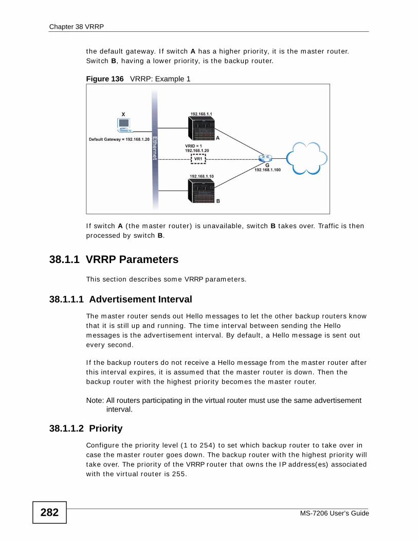
Chapter 38 VRRP
MS-7206 User’s Guide282
the default gateway. If switch A has a higher priority, it is the master router. Switch B, having a lower priority, is the backup router.
Figure 136 VRRP: Example 1
If switch A (the master router) is unavailable, switch B takes over. Traffic is then processed by switch B.
38.1.1 VRRP Parameters This section describes some VRRP parameters.
38.1.1.1 Advertisement Interval The master router sends out Hello messages to let the other backup routers know that it is still up and running. The time interval between sending the Hello messages is the advertisement interval. By default, a Hello message is sent out every second.
If the backup routers do not receive a Hello message from the master router after this interval expires, it is assumed that the master router is down. Then the backup router with the highest priority becomes the master router.
Note: All routers participating in the virtual router must use the same advertisement interval.
38.1.1.2 Priority Configure the priority level (1 to 254) to set which backup router to take over in case the master router goes down. The backup router with the highest priority will take over. The priority of the VRRP router that owns the IP address(es) associated with the virtual router is 255.
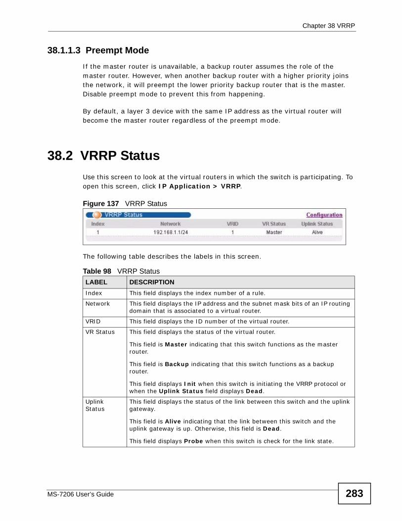
Chapter 38 VRRP
MS-7206 User’s Guide 283
38.1.1.3 Preempt Mode If the master router is unavailable, a backup router assumes the role of the master router. However, when another backup router with a higher priority joins the network, it will preempt the lower priority backup router that is the master. Disable preempt mode to prevent this from happening.
By default, a layer 3 device with the same IP address as the virtual router will become the master router regardless of the preempt mode.
38.2 VRRP Status Use this screen to look at the virtual routers in which the switch is participating. To open this screen, click IP Application > VRRP.
Figure 137 VRRP Status
The following table describes the labels in this screen.
Table 98 VRRP StatusLABEL DESCRIPTIONIndex This field displays the index number of a rule.
Network This field displays the IP address and the subnet mask bits of an IP routing domain that is associated to a virtual router.
VRID This field displays the ID number of the virtual router.
VR Status This field displays the status of the virtual router.
This field is Master indicating that this switch functions as the master router.
This field is Backup indicating that this switch functions as a backup router.
This field displays Init when this switch is initiating the VRRP protocol or when the Uplink Status field displays Dead.
Uplink Status
This field displays the status of the link between this switch and the uplink gateway.
This field is Alive indicating that the link between this switch and the uplink gateway is up. Otherwise, this field is Dead.
This field displays Probe when this switch is check for the link state.
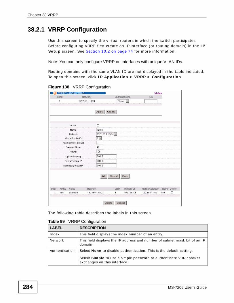
Chapter 38 VRRP
MS-7206 User’s Guide284
38.2.1 VRRP ConfigurationUse this screen to specify the virtual routers in which the switch participates. Before configuring VRRP, first create an IP interface (or routing domain) in the IP Setup screen. See Section 10.2 on page 74 for more information.
Note: You can only configure VRRP on interfaces with unique VLAN IDs.
Routing domains with the same VLAN ID are not displayed in the table indicated. To open this screen, click IP Application > VRRP > Configuration.
Figure 138 VRRP Configuration
The following table describes the labels in this screen.
Table 99 VRRP ConfigurationLABEL DESCRIPTIONIndex This field displays the index number of an entry.
Network This field displays the IP address and number of subnet mask bit of an IP domain.
Authentication Select None to disable authentication. This is the default setting.
Select Simple to use a simple password to authenticate VRRP packet exchanges on this interface.
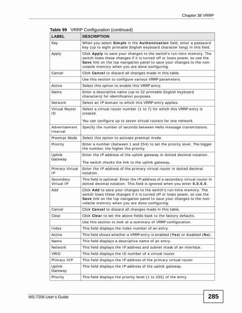
Chapter 38 VRRP
MS-7206 User’s Guide 285
Key When you select Simple in the Authentication field, enter a password key (up to eight printable English keyboard character long) in this field.
Apply Click Apply to save your changes to the switch’s run-time memory. The switch loses these changes if it is turned off or loses power, so use the Save link on the top navigation panel to save your changes to the non-volatile memory when you are done configuring.
Cancel Click Cancel to discard all changes made in this table.
Use this section to configure various VRRP parameters.
Active Select this option to enable this VRRP entry.
Name Enter a descriptive name (up to 32 printable English keyboard characters) for identification purposes.
Network Select an IP domain to which this VRRP entry applies.
Virtual Router ID
Select a virtual router number (1 to 7) for which this VRRP entry is created.
You can configure up to seven virtual routers for one network.
Advertisement Interval
Specify the number of seconds between Hello message transmissions.
Preempt Mode Select this option to activate preempt mode.
Priority Enter a number (between 1 and 254) to set the priority level. The bigger the number, the higher the priority.
Uplink Gateway
Enter the IP address of the uplink gateway in dotted decimal notation.
The switch checks the link to the uplink gateway.
Primary Virtual IP
Enter the IP address of the primary virtual router in dotted decimal notation.
Secondary Virtual IP
This field is optional. Enter the IP address of a secondary virtual router in dotted decimal notation. This field is ignored when you enter 0.0.0.0.
Add Click Add to save your changes to the switch’s run-time memory. The switch loses these changes if it is turned off or loses power, so use the Save link on the top navigation panel to save your changes to the non-volatile memory when you are done configuring.
Cancel Click Cancel to discard all changes made in this table.
Clear Click Clear to set the above fields back to the factory defaults.
Use this section to look at a summary of VRRP configuration.
Index This field displays the index number of an entry.
Active This field shows whether a VRRP entry is enabled (Yes) or disabled (No).
Name This field displays a descriptive name of an entry.
Network This field displays the IP address and subnet mask of an interface.
VRID This field displays the ID number of a virtual router.
Primary VIP This field displays the IP address of the primary virtual router.
Uplink Gateway
This field displays the IP address of the uplink gateway.
Priority This field displays the priority level (1 to 255) of the entry.
Table 99 VRRP Configuration (continued)LABEL DESCRIPTION
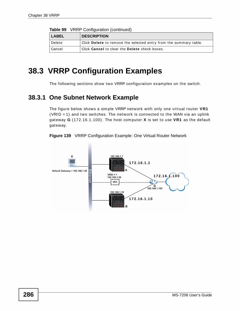
Chapter 38 VRRP
MS-7206 User’s Guide286
38.3 VRRP Configuration Examples The following sections show two VRRP configuration examples on the switch.
38.3.1 One Subnet Network Example The figure below shows a simple VRRP network with only one virtual router VR1 (VRID =1) and two switches. The network is connected to the WAN via an uplink gateway G (172.16.1.100). The host computer X is set to use VR1 as the default gateway.
Figure 139 VRRP Configuration Example: One Virtual Router Network
Delete Click Delete to remove the selected entry from the summary table.
Cancel Click Cancel to clear the Delete check boxes.
Table 99 VRRP Configuration (continued)LABEL DESCRIPTION
172.16.1.1
172.16.1.10
172.16.1.100
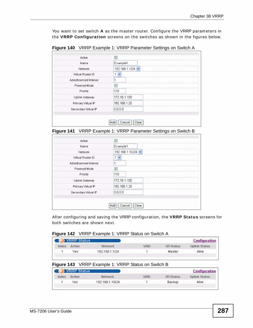
Chapter 38 VRRP
MS-7206 User’s Guide 287
You want to set switch A as the master router. Configure the VRRP parameters in the VRRP Configuration screens on the switches as shown in the figures below.
Figure 140 VRRP Example 1: VRRP Parameter Settings on Switch A
Figure 141 VRRP Example 1: VRRP Parameter Settings on Switch B
After configuring and saving the VRRP configuration, the VRRP Status screens for both switches are shown next.
Figure 142 VRRP Example 1: VRRP Status on Switch A
Figure 143 VRRP Example 1: VRRP Status on Switch B
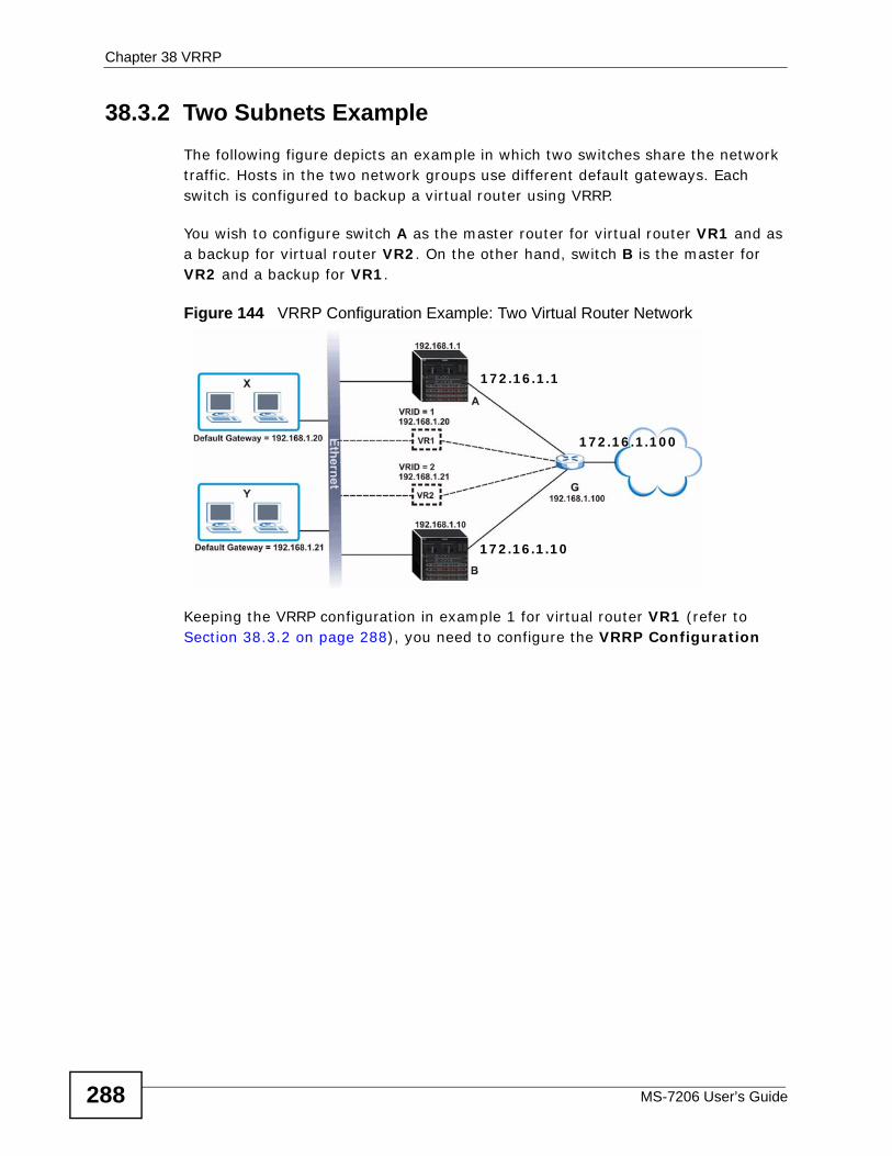
Chapter 38 VRRP
MS-7206 User’s Guide288
38.3.2 Two Subnets ExampleThe following figure depicts an example in which two switches share the network traffic. Hosts in the two network groups use different default gateways. Each switch is configured to backup a virtual router using VRRP.
You wish to configure switch A as the master router for virtual router VR1 and as a backup for virtual router VR2. On the other hand, switch B is the master for VR2 and a backup for VR1.
Figure 144 VRRP Configuration Example: Two Virtual Router Network
Keeping the VRRP configuration in example 1 for virtual router VR1 (refer to Section 38.3.2 on page 288), you need to configure the VRRP Configuration
172.16.1.1
172.16.1.10
172.16.1.100
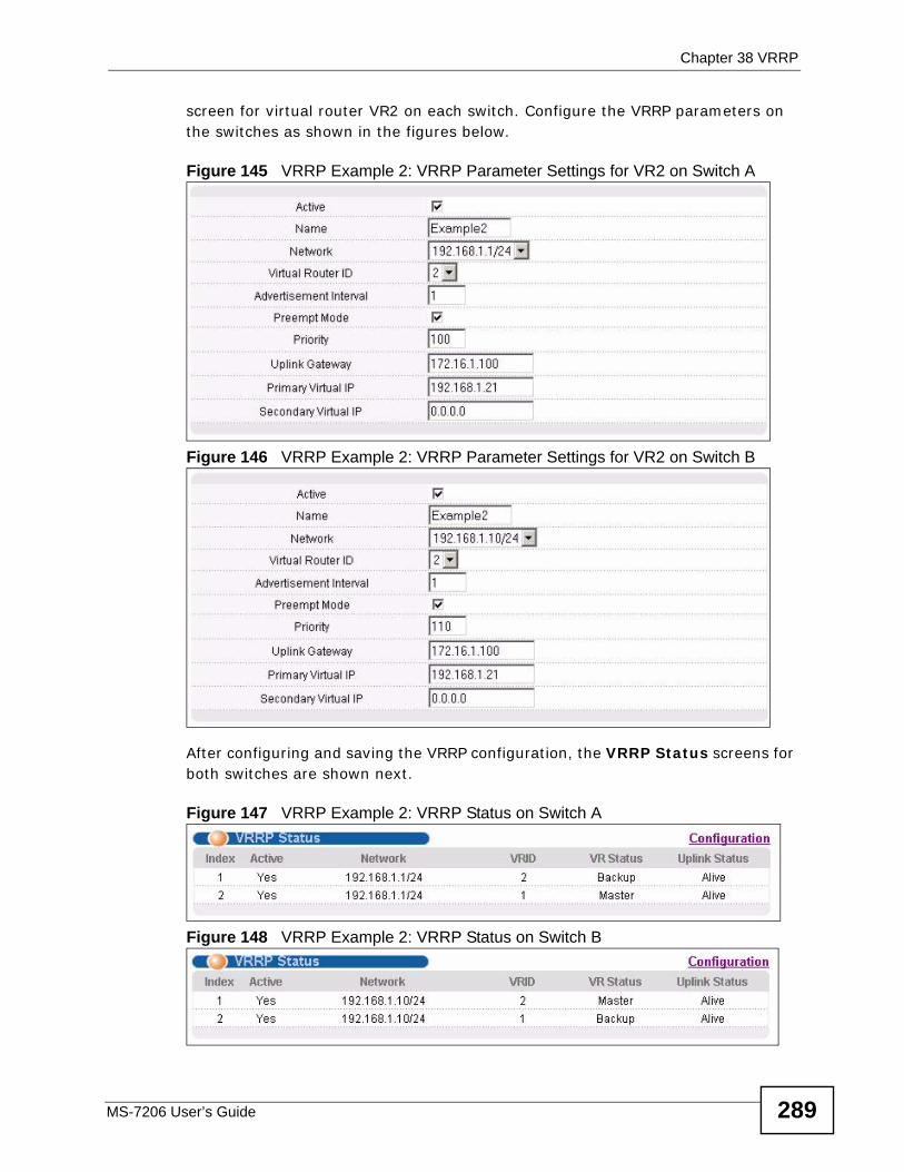
Chapter 38 VRRP
MS-7206 User’s Guide 289
screen for virtual router VR2 on each switch. Configure the VRRP parameters on the switches as shown in the figures below.
Figure 145 VRRP Example 2: VRRP Parameter Settings for VR2 on Switch A
Figure 146 VRRP Example 2: VRRP Parameter Settings for VR2 on Switch B
After configuring and saving the VRRP configuration, the VRRP Status screens for both switches are shown next.
Figure 147 VRRP Example 2: VRRP Status on Switch A
Figure 148 VRRP Example 2: VRRP Status on Switch B

Chapter 38 VRRP
MS-7206 User’s Guide290
291
PART VIManage
Maintenance (293)
Access Control (301)
Diagnostic (321)
Syslog (323)
Cluster Management (327)
MAC Table (335)
IP Table (339)
ARP Table (343)
Routing Table (345)
Configure Clone (347)

292
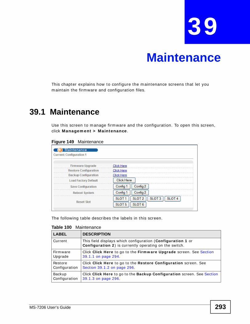
MS-7206 User’s Guide 293
CHAPTER 39 Maintenance
This chapter explains how to configure the maintenance screens that let you maintain the firmware and configuration files.
39.1 MaintenanceUse this screen to manage firmware and the configuration. To open this screen, click Management > Maintenance.
Figure 149 Maintenance
The following table describes the labels in this screen.
Table 100 MaintenanceLABEL DESCRIPTIONCurrent This field displays which configuration (Configuration 1 or
Configuration 2) is currently operating on the switch.
Firmware Upgrade
Click Click Here to go to the Firmware Upgrade screen. See Section 39.1.1 on page 294.
Restore Configuration
Click Click Here to go to the Restore Configuration screen. See Section 39.1.2 on page 296.
Backup Configuration
Click Click Here to go to the Backup Configuration screen. See Section 39.1.3 on page 296.
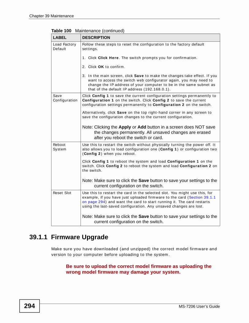
Chapter 39 Maintenance
MS-7206 User’s Guide294
39.1.1 Firmware UpgradeMake sure you have downloaded (and unzipped) the correct model firmware and version to your computer before uploading to the system.
Be sure to upload the correct model firmware as uploading the wrong model firmware may damage your system.
Load Factory Default
Follow these steps to reset the configuration to the factory default settings.
1. Click Click Here. The switch prompts you for confirmation.
2. Click OK to confirm.
3. In the main screen, click Save to make the changes take effect. If you want to access the switch web configurator again, you may need to change the IP address of your computer to be in the same subnet as that of the default IP address (192.168.0.1).
Save Configuration
Click Config 1 to save the current configuration settings permanently to Configuration 1 on the switch. Click Config 2 to save the current configuration settings permanently to Configuration 2 on the switch.
Alternatively, click Save on the top right-hand corner in any screen to save the configuration changes to the current configuration.
Note: Clicking the Apply or Add button in a screen does NOT save the changes permanently. All unsaved changes are erased after you reboot the switch or card.
Reboot System
Use this to restart the switch without physically turning the power off. It also allows you to load configuration one (Config 1) or configuration two (Config 2) when you reboot.
Click Config 1 to reboot the system and load Configuration 1 on the switch. Click Config 2 to reboot the system and load Configuration 2 on the switch.
Note: Make sure to click the Save button to save your settings to the current configuration on the switch.
Reset Slot Use this to restart the card in the selected slot. You might use this, for example, if you have just uploaded firmware to the card (Section 39.1.1 on page 294) and want the card to start running it. The card restarts using the last-saved configuration. Any unsaved changes are lost.
Note: Make sure to click the Save button to save your settings to the current configuration on the switch.
Table 100 Maintenance (continued)LABEL DESCRIPTION
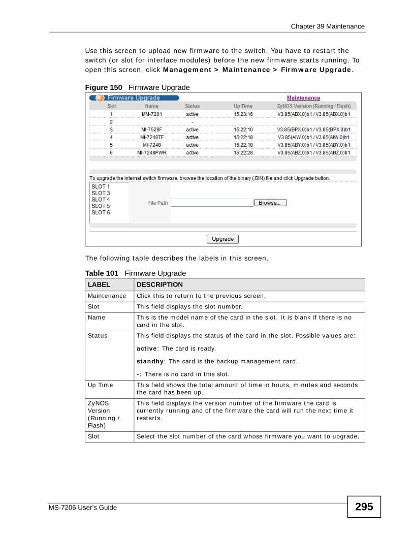
Chapter 39 Maintenance
MS-7206 User’s Guide 295
Use this screen to upload new firmware to the switch. You have to restart the switch (or slot for interface modules) before the new firmware starts running. To open this screen, click Management > Maintenance > Firmware Upgrade.
Figure 150 Firmware Upgrade
The following table describes the labels in this screen.
Table 101 Firmware Upgrade LABEL DESCRIPTIONMaintenance Click this to return to the previous screen.
Slot This field displays the slot number.
Name This is the model name of the card in the slot. It is blank if there is no card in the slot.
Status This field displays the status of the card in the slot. Possible values are:
active: The card is ready.
standby: The card is the backup management card.
-: There is no card in this slot.
Up Time This field shows the total amount of time in hours, minutes and seconds the card has been up.
ZyNOS Version (Running / Flash)
This field displays the version number of the firmware the card is currently running and of the firmware the card will run the next time it restarts.
Slot Select the slot number of the card whose firmware you want to upgrade.
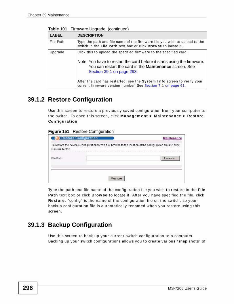
Chapter 39 Maintenance
MS-7206 User’s Guide296
39.1.2 Restore ConfigurationUse this screen to restore a previously saved configuration from your computer to the switch. To open this screen, click Management > Maintenance > Restore Configuration.
Figure 151 Restore Configuration
Type the path and file name of the configuration file you wish to restore in the File Path text box or click Browse to locate it. After you have specified the file, click Restore. "config" is the name of the configuration file on the switch, so your backup configuration file is automatically renamed when you restore using this screen.
39.1.3 Backup ConfigurationUse this screen to back up your current switch configuration to a computer. Backing up your switch configurations allows you to create various “snap shots” of
File Path Type the path and file name of the firmware file you wish to upload to the switch in the File Path text box or click Browse to locate it.
Upgrade Click this to upload the specified firmware to the specified card.
Note: You have to restart the card before it starts using the firmware. You can restart the card in the Maintenance screen. See Section 39.1 on page 293.
After the card has restarted, see the System Info screen to verify your current firmware version number. See Section 7.1 on page 61.
Table 101 Firmware Upgrade (continued)LABEL DESCRIPTION
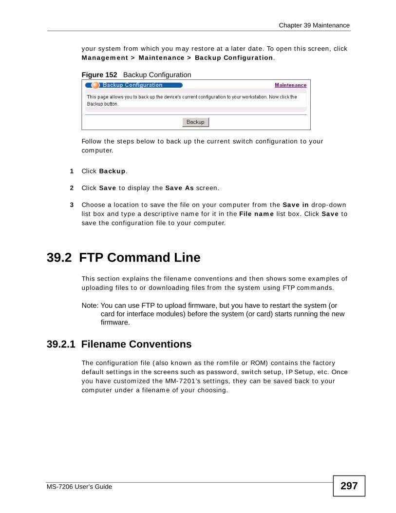
Chapter 39 Maintenance
MS-7206 User’s Guide 297
your system from which you may restore at a later date. To open this screen, click Management > Maintenance > Backup Configuration.
Figure 152 Backup Configuration
Follow the steps below to back up the current switch configuration to your computer.
1 Click Backup.
2 Click Save to display the Save As screen.
3 Choose a location to save the file on your computer from the Save in drop-down list box and type a descriptive name for it in the File name list box. Click Save to save the configuration file to your computer.
39.2 FTP Command LineThis section explains the filename conventions and then shows some examples of uploading files to or downloading files from the system using FTP commands.
Note: You can use FTP to upload firmware, but you have to restart the system (or card for interface modules) before the system (or card) starts running the new firmware.
39.2.1 Filename Conventions The configuration file (also known as the romfile or ROM) contains the factory default settings in the screens such as password, switch setup, IP Setup, etc. Once you have customized the MM-7201’s settings, they can be saved back to your computer under a filename of your choosing.
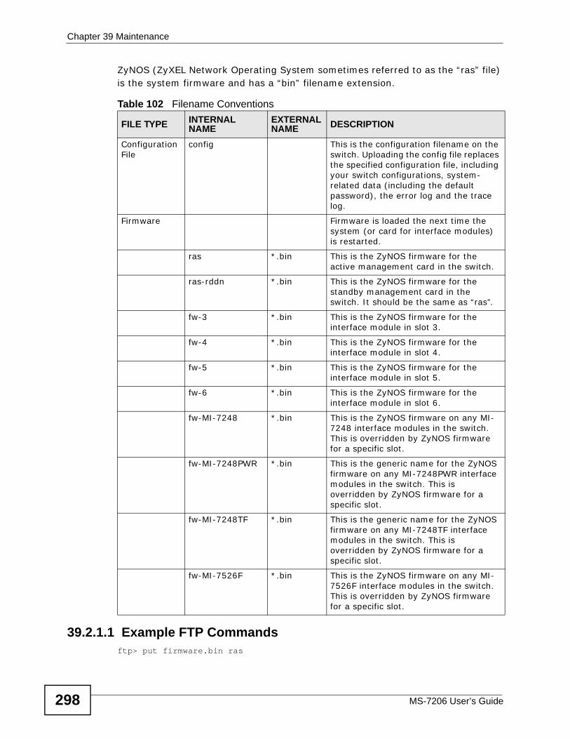
Chapter 39 Maintenance
MS-7206 User’s Guide298
ZyNOS (ZyXEL Network Operating System sometimes referred to as the “ras” file) is the system firmware and has a “bin” filename extension.
39.2.1.1 Example FTP Commandsftp> put firmware.bin ras
Table 102 Filename Conventions
FILE TYPE INTERNAL NAME
EXTERNAL NAME DESCRIPTION
Configuration File
config This is the configuration filename on the switch. Uploading the config file replaces the specified configuration file, including your switch configurations, system-related data (including the default password), the error log and the trace log.
Firmware Firmware is loaded the next time the system (or card for interface modules) is restarted.
ras *.bin This is the ZyNOS firmware for the active management card in the switch.
ras-rddn *.bin This is the ZyNOS firmware for the standby management card in the switch. It should be the same as “ras”.
fw-3 *.bin This is the ZyNOS firmware for the interface module in slot 3.
fw-4 *.bin This is the ZyNOS firmware for the interface module in slot 4.
fw-5 *.bin This is the ZyNOS firmware for the interface module in slot 5.
fw-6 *.bin This is the ZyNOS firmware for the interface module in slot 6.
fw-MI-7248 *.bin This is the ZyNOS firmware on any MI-7248 interface modules in the switch. This is overridden by ZyNOS firmware for a specific slot.
fw-MI-7248PWR *.bin This is the generic name for the ZyNOS firmware on any MI-7248PWR interface modules in the switch. This is overridden by ZyNOS firmware for a specific slot.
fw-MI-7248TF *.bin This is the generic name for the ZyNOS firmware on any MI-7248TF interface modules in the switch. This is overridden by ZyNOS firmware for a specific slot.
fw-MI-7526F *.bin This is the ZyNOS firmware on any MI-7526F interface modules in the switch. This is overridden by ZyNOS firmware for a specific slot.
Chapter 39 Maintenance
MS-7206 User’s Guide 299
This is a sample FTP session showing the transfer of the computer file "firmware.bin" to the switch.
ftp> get config config.cfg
This is a sample FTP session saving the current configuration to a file called “config.cfg” on your computer.
If your (T)FTP client does not allow you to have a destination filename different than the source, you will need to rename them first as the switch only recognizes the names in Table 102 on page 298. Be sure you keep unaltered copies of files for later use.
Be sure to upload the correct model firmware as uploading the wrong model firmware may damage your system.
39.2.2 FTP Command Line Procedure
1 Launch the FTP client on your computer.
2 Enter open, followed by a space and the IP address of your switch.
3 Enter your username as requested (the default is “admin”).
4 Enter your password as requested (the default is “1234”).
5 Enter bin to set transfer mode to binary.
6 Use put to transfer files from the computer to the switch, for example, put firmware.bin ras transfers the firmware on your computer (firmware.bin) to the switch and renames it to “ras”. Similarly, put config.cfg config transfers the configuration file on your computer (config.cfg) to the switch and renames it to “config”. Likewise get config config.cfg transfers the configuration file on the switch to your computer and renames it to “config.cfg”. See Table 102 on page 298 for more information on filename conventions.
7 Enter quit to exit the ftp prompt.
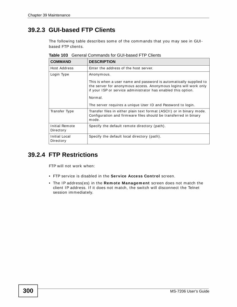
Chapter 39 Maintenance
MS-7206 User’s Guide300
39.2.3 GUI-based FTP ClientsThe following table describes some of the commands that you may see in GUI-based FTP clients.
39.2.4 FTP Restrictions FTP will not work when:
• FTP service is disabled in the Service Access Control screen.
• The IP address(es) in the Remote Management screen does not match the client IP address. If it does not match, the switch will disconnect the Telnet session immediately.
Table 103 General Commands for GUI-based FTP ClientsCOMMAND DESCRIPTIONHost Address Enter the address of the host server.
Login Type Anonymous.
This is when a user name and password is automatically supplied to the server for anonymous access. Anonymous logins will work only if your ISP or service administrator has enabled this option.
Normal.
The server requires a unique User ID and Password to login.
Transfer Type Transfer files in either plain text format (ASCII) or in binary mode. Configuration and firmware files should be transferred in binary mode.
Initial Remote Directory
Specify the default remote directory (path).
Initial Local Directory
Specify the default local directory (path).
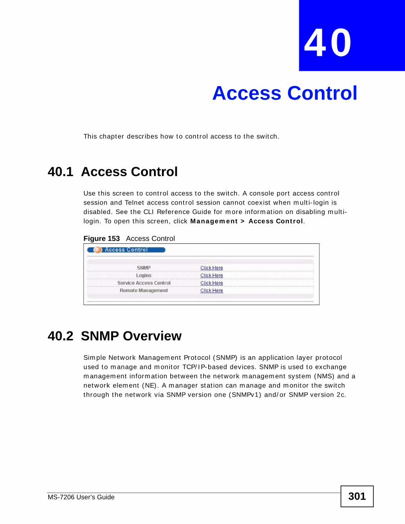
MS-7206 User’s Guide 301
CHAPTER 40 Access Control
This chapter describes how to control access to the switch.
40.1 Access ControlUse this screen to control access to the switch. A console port access control session and Telnet access control session cannot coexist when multi-login is disabled. See the CLI Reference Guide for more information on disabling multi-login. To open this screen, click Management > Access Control.
Figure 153 Access Control
40.2 SNMP OverviewSimple Network Management Protocol (SNMP) is an application layer protocol used to manage and monitor TCP/IP-based devices. SNMP is used to exchange management information between the network management system (NMS) and a network element (NE). A manager station can manage and monitor the switch through the network via SNMP version one (SNMPv1) and/or SNMP version 2c.
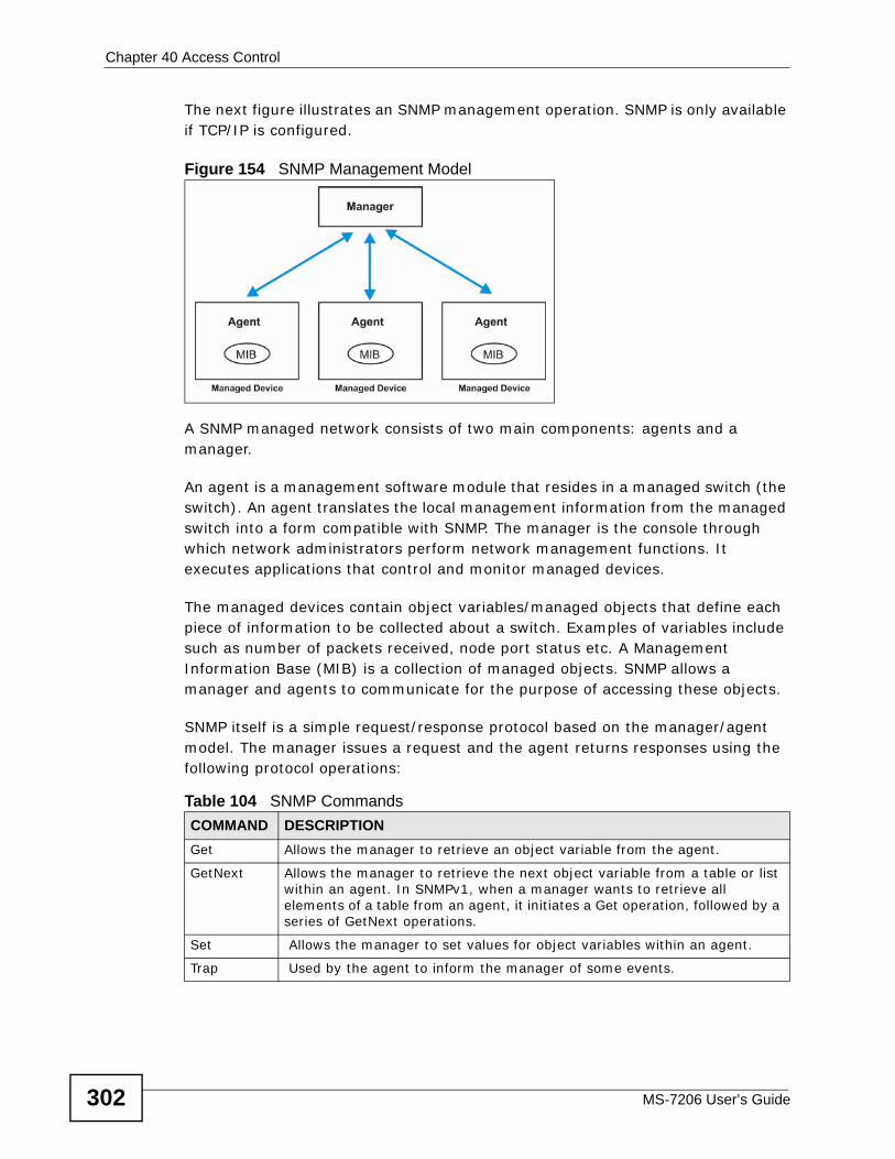
Chapter 40 Access Control
MS-7206 User’s Guide302
The next figure illustrates an SNMP management operation. SNMP is only available if TCP/IP is configured.
Figure 154 SNMP Management Model
A SNMP managed network consists of two main components: agents and a manager.
An agent is a management software module that resides in a managed switch (the switch). An agent translates the local management information from the managed switch into a form compatible with SNMP. The manager is the console through which network administrators perform network management functions. It executes applications that control and monitor managed devices.
The managed devices contain object variables/managed objects that define each piece of information to be collected about a switch. Examples of variables include such as number of packets received, node port status etc. A Management Information Base (MIB) is a collection of managed objects. SNMP allows a manager and agents to communicate for the purpose of accessing these objects.
SNMP itself is a simple request/response protocol based on the manager/agent model. The manager issues a request and the agent returns responses using the following protocol operations:
Table 104 SNMP CommandsCOMMAND DESCRIPTIONGet Allows the manager to retrieve an object variable from the agent.
GetNext Allows the manager to retrieve the next object variable from a table or list within an agent. In SNMPv1, when a manager wants to retrieve all elements of a table from an agent, it initiates a Get operation, followed by a series of GetNext operations.
Set Allows the manager to set values for object variables within an agent.
Trap Used by the agent to inform the manager of some events.
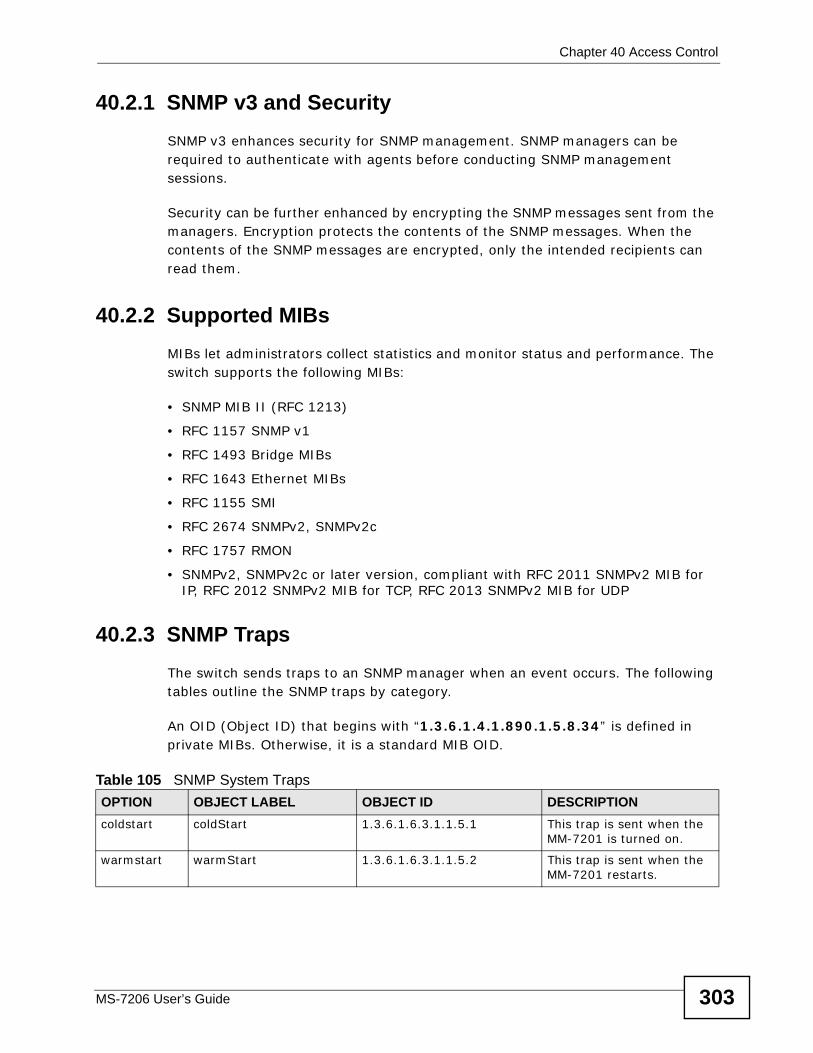
Chapter 40 Access Control
MS-7206 User’s Guide 303
40.2.1 SNMP v3 and SecuritySNMP v3 enhances security for SNMP management. SNMP managers can be required to authenticate with agents before conducting SNMP management sessions.
Security can be further enhanced by encrypting the SNMP messages sent from the managers. Encryption protects the contents of the SNMP messages. When the contents of the SNMP messages are encrypted, only the intended recipients can read them.
40.2.2 Supported MIBsMIBs let administrators collect statistics and monitor status and performance. The switch supports the following MIBs:
• SNMP MIB II (RFC 1213)
• RFC 1157 SNMP v1
• RFC 1493 Bridge MIBs
• RFC 1643 Ethernet MIBs
• RFC 1155 SMI
• RFC 2674 SNMPv2, SNMPv2c
• RFC 1757 RMON
• SNMPv2, SNMPv2c or later version, compliant with RFC 2011 SNMPv2 MIB for IP, RFC 2012 SNMPv2 MIB for TCP, RFC 2013 SNMPv2 MIB for UDP
40.2.3 SNMP Traps The switch sends traps to an SNMP manager when an event occurs. The following tables outline the SNMP traps by category.
An OID (Object ID) that begins with “1.3.6.1.4.1.890.1.5.8.34” is defined in private MIBs. Otherwise, it is a standard MIB OID.
Table 105 SNMP System Traps OPTION OBJECT LABEL OBJECT ID DESCRIPTIONcoldstart coldStart 1.3.6.1.6.3.1.1.5.1 This trap is sent when the
MM-7201 is turned on.
warmstart warmStart 1.3.6.1.6.3.1.1.5.2 This trap is sent when the MM-7201 restarts.
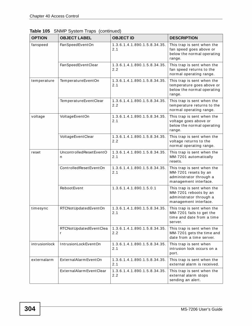
Chapter 40 Access Control
MS-7206 User’s Guide304
fanspeed FanSpeedEventOn 1.3.6.1.4.1.890.1.5.8.34.35.2.1
This trap is sent when the fan speed goes above or below the normal operating range.
FanSpeedEventClear 1.3.6.1.4.1.890.1.5.8.34.35.2.2
This trap is sent when the fan speed returns to the normal operating range.
temperature TemperatureEventOn 1.3.6.1.4.1.890.1.5.8.34.35.2.1
This trap is sent when the temperature goes above or below the normal operating range.
TemperatureEventClear 1.3.6.1.4.1.890.1.5.8.34.35.2.2
This trap is sent when the temperature returns to the normal operating range.
voltage VoltageEventOn 1.3.6.1.4.1.890.1.5.8.34.35.2.1
This trap is sent when the voltage goes above or below the normal operating range.
VoltageEventClear 1.3.6.1.4.1.890.1.5.8.34.35.2.2
This trap is sent when the voltage returns to the normal operating range.
reset UncontrolledResetEventOn
1.3.6.1.4.1.890.1.5.8.34.35.2.1
This trap is sent when the MM-7201 automatically resets.
ControlledResetEventOn 1.3.6.1.4.1.890.1.5.8.34.35.2.1
This trap is sent when the MM-7201 resets by an administrator through a management interface.
RebootEvent 1.3.6.1.4.1.890.1.5.0.1 This trap is sent when the MM-7201 reboots by an administrator through a management interface.
timesync RTCNotUpdatedEventOn 1.3.6.1.4.1.890.1.5.8.34.35.2.1
This trap is sent when the MM-7201 fails to get the time and date from a time server.
RTCNotUpdatedEventClear
1.3.6.1.4.1.890.1.5.8.34.35.2.2
This trap is sent when the MM-7201 gets the time and date from a time server.
intrusionlock IntrusionLockEventOn 1.3.6.1.4.1.890.1.5.8.34.35.2.1
This trap is sent when intrusion lock occurs on a port.
externalarm ExternalAlarmEventOn 1.3.6.1.4.1.890.1.5.8.34.35.2.1
This trap is sent when the external alarm is received.
ExternalAlarmEventClear 1.3.6.1.4.1.890.1.5.8.34.35.2.2
This trap is sent when the external alarm stops sending an alert.
Table 105 SNMP System Traps (continued)OPTION OBJECT LABEL OBJECT ID DESCRIPTION
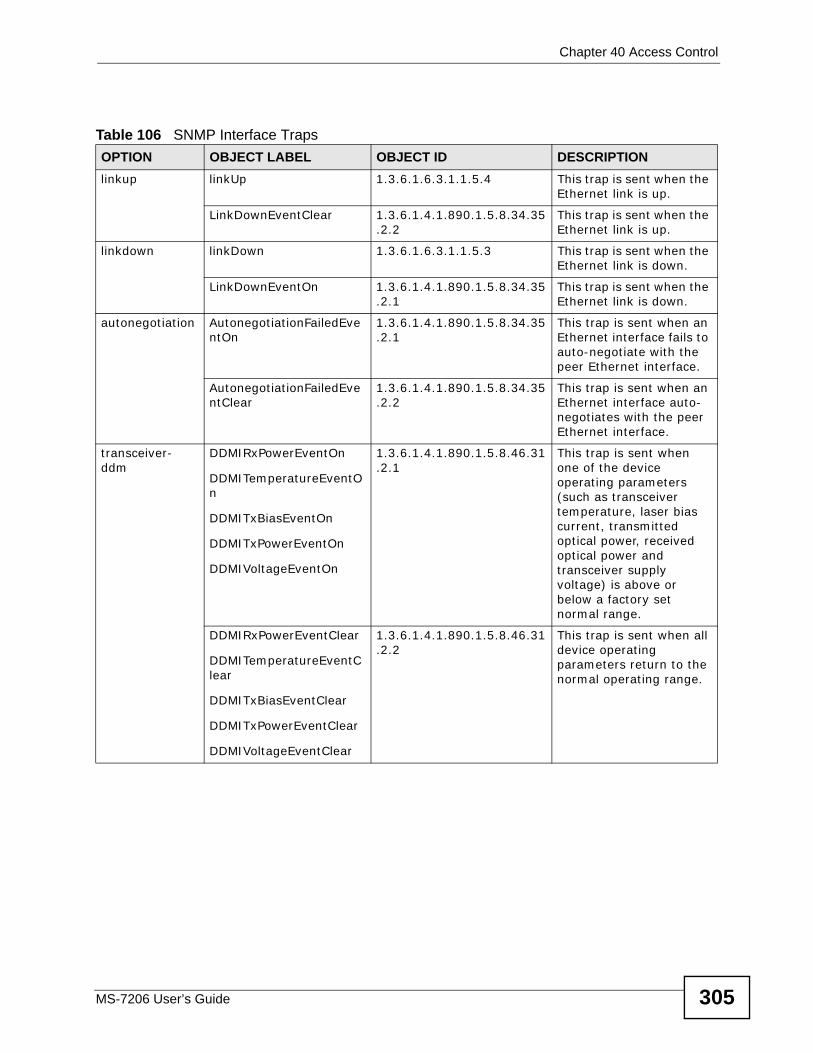
Chapter 40 Access Control
MS-7206 User’s Guide 305
Table 106 SNMP Interface Traps OPTION OBJECT LABEL OBJECT ID DESCRIPTIONlinkup linkUp 1.3.6.1.6.3.1.1.5.4 This trap is sent when the
Ethernet link is up.
LinkDownEventClear 1.3.6.1.4.1.890.1.5.8.34.35.2.2
This trap is sent when the Ethernet link is up.
linkdown linkDown 1.3.6.1.6.3.1.1.5.3 This trap is sent when the Ethernet link is down.
LinkDownEventOn 1.3.6.1.4.1.890.1.5.8.34.35.2.1
This trap is sent when the Ethernet link is down.
autonegotiation AutonegotiationFailedEventOn
1.3.6.1.4.1.890.1.5.8.34.35.2.1
This trap is sent when an Ethernet interface fails to auto-negotiate with the peer Ethernet interface.
AutonegotiationFailedEventClear
1.3.6.1.4.1.890.1.5.8.34.35.2.2
This trap is sent when an Ethernet interface auto-negotiates with the peer Ethernet interface.
transceiver-ddm
DDMIRxPowerEventOn
DDMITemperatureEventOn
DDMITxBiasEventOn
DDMITxPowerEventOn
DDMIVoltageEventOn
1.3.6.1.4.1.890.1.5.8.46.31.2.1
This trap is sent when one of the device operating parameters (such as transceiver temperature, laser bias current, transmitted optical power, received optical power and transceiver supply voltage) is above or below a factory set normal range.
DDMIRxPowerEventClear
DDMITemperatureEventClear
DDMITxBiasEventClear
DDMITxPowerEventClear
DDMIVoltageEventClear
1.3.6.1.4.1.890.1.5.8.46.31.2.2
This trap is sent when all device operating parameters return to the normal operating range.
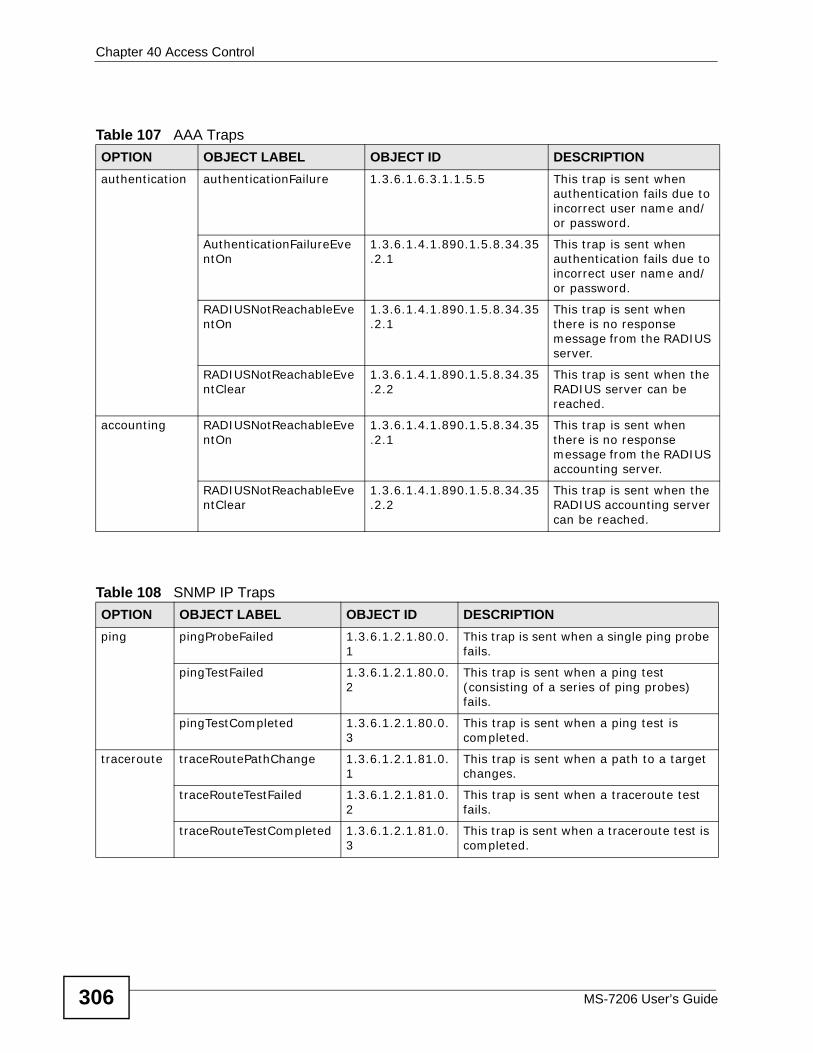
Chapter 40 Access Control
MS-7206 User’s Guide306
Table 107 AAA Traps OPTION OBJECT LABEL OBJECT ID DESCRIPTIONauthentication authenticationFailure 1.3.6.1.6.3.1.1.5.5 This trap is sent when
authentication fails due to incorrect user name and/or password.
AuthenticationFailureEventOn
1.3.6.1.4.1.890.1.5.8.34.35.2.1
This trap is sent when authentication fails due to incorrect user name and/or password.
RADIUSNotReachableEventOn
1.3.6.1.4.1.890.1.5.8.34.35.2.1
This trap is sent when there is no response message from the RADIUS server.
RADIUSNotReachableEventClear
1.3.6.1.4.1.890.1.5.8.34.35.2.2
This trap is sent when the RADIUS server can be reached.
accounting RADIUSNotReachableEventOn
1.3.6.1.4.1.890.1.5.8.34.35.2.1
This trap is sent when there is no response message from the RADIUS accounting server.
RADIUSNotReachableEventClear
1.3.6.1.4.1.890.1.5.8.34.35.2.2
This trap is sent when the RADIUS accounting server can be reached.
Table 108 SNMP IP Traps OPTION OBJECT LABEL OBJECT ID DESCRIPTIONping pingProbeFailed 1.3.6.1.2.1.80.0.
1This trap is sent when a single ping probe fails.
pingTestFailed 1.3.6.1.2.1.80.0.2
This trap is sent when a ping test (consisting of a series of ping probes) fails.
pingTestCompleted 1.3.6.1.2.1.80.0.3
This trap is sent when a ping test is completed.
traceroute traceRoutePathChange 1.3.6.1.2.1.81.0.1
This trap is sent when a path to a target changes.
traceRouteTestFailed 1.3.6.1.2.1.81.0.2
This trap is sent when a traceroute test fails.
traceRouteTestCompleted 1.3.6.1.2.1.81.0.3
This trap is sent when a traceroute test is completed.
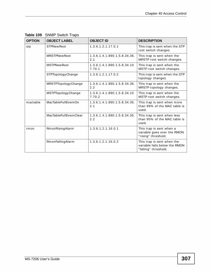
Chapter 40 Access Control
MS-7206 User’s Guide 307
Table 109 SNMP Switch Traps OPTION OBJECT LABEL OBJECT ID DESCRIPTIONstp STPNewRoot 1.3.6.1.2.1.17.0.1 This trap is sent when the STP
root switch changes.
MRSTPNewRoot 1.3.6.1.4.1.890.1.5.8.34.36.2.1
This trap is sent when the MRSTP root switch changes.
MSTPNewRoot 1.3.6.1.4.1.890.1.5.8.34.107.70.1
This trap is sent when the MSTP root switch changes.
STPTopologyChange 1.3.6.1.2.1.17.0.2 This trap is sent when the STP topology changes.
MRSTPTopologyChange 1.3.6.1.4.1.890.1.5.8.34.36.2.2
This trap is sent when the MRSTP topology changes.
MSTPTopologyChange 1.3.6.1.4.1.890.1.5.8.34.107.70.2
This trap is sent when the MSTP root switch changes.
mactable MacTableFullEventOn 1.3.6.1.4.1.890.1.5.8.34.35.2.1
This trap is sent when more than 99% of the MAC table is used.
MacTableFullEventClear 1.3.6.1.4.1.890.1.5.8.34.35.2.2
This trap is sent when less than 95% of the MAC table is used.
rmon RmonRisingAlarm 1.3.6.1.2.1.16.0.1 This trap is sent when a variable goes over the RMON "rising" threshold.
RmonFallingAlarm 1.3.6.1.2.1.16.0.2 This trap is sent when the variable falls below the RMON "falling" threshold.
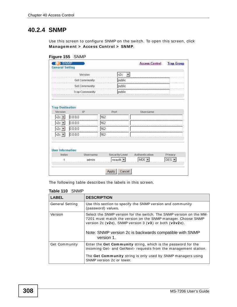
Chapter 40 Access Control
MS-7206 User’s Guide308
40.2.4 SNMPUse this screen to configure SNMP on the switch. To open this screen, click Management > Access Control > SNMP.
Figure 155 SNMP
The following table describes the labels in this screen.
Table 110 SNMP LABEL DESCRIPTIONGeneral Setting Use this section to specify the SNMP version and community
(password) values.
Version Select the SNMP version for the switch. The SNMP version on the MM-7201 must match the version on the SNMP manager. Choose SNMP version 2c (v2c), SNMP version 3 (v3) or both (v3v2c).
Note: SNMP version 2c is backwards compatible with SNMP version 1.
Get Community Enter the Get Community string, which is the password for the incoming Get- and GetNext- requests from the management station.
The Get Community string is only used by SNMP managers using SNMP version 2c or lower.
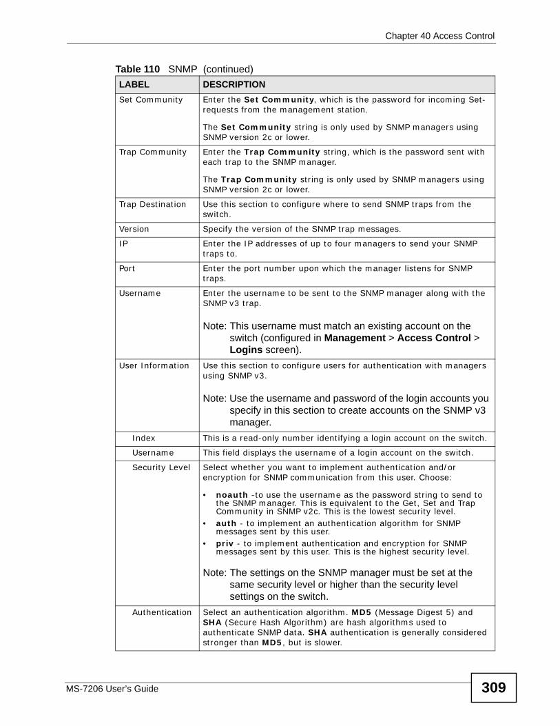
Chapter 40 Access Control
MS-7206 User’s Guide 309
Set Community Enter the Set Community, which is the password for incoming Set- requests from the management station.
The Set Community string is only used by SNMP managers using SNMP version 2c or lower.
Trap Community Enter the Trap Community string, which is the password sent with each trap to the SNMP manager.
The Trap Community string is only used by SNMP managers using SNMP version 2c or lower.
Trap Destination Use this section to configure where to send SNMP traps from the switch.
Version Specify the version of the SNMP trap messages.
IP Enter the IP addresses of up to four managers to send your SNMP traps to.
Port Enter the port number upon which the manager listens for SNMP traps.
Username Enter the username to be sent to the SNMP manager along with the SNMP v3 trap.
Note: This username must match an existing account on the switch (configured in Management > Access Control > Logins screen).
User Information Use this section to configure users for authentication with managers using SNMP v3.
Note: Use the username and password of the login accounts you specify in this section to create accounts on the SNMP v3 manager.
Index This is a read-only number identifying a login account on the switch.
Username This field displays the username of a login account on the switch.
Security Level Select whether you want to implement authentication and/or encryption for SNMP communication from this user. Choose:
• noauth -to use the username as the password string to send to the SNMP manager. This is equivalent to the Get, Set and Trap Community in SNMP v2c. This is the lowest security level.
• auth - to implement an authentication algorithm for SNMP messages sent by this user.
• priv - to implement authentication and encryption for SNMP messages sent by this user. This is the highest security level.
Note: The settings on the SNMP manager must be set at the same security level or higher than the security level settings on the switch.
Authentication Select an authentication algorithm. MD5 (Message Digest 5) and SHA (Secure Hash Algorithm) are hash algorithms used to authenticate SNMP data. SHA authentication is generally considered stronger than MD5, but is slower.
Table 110 SNMP (continued)LABEL DESCRIPTION
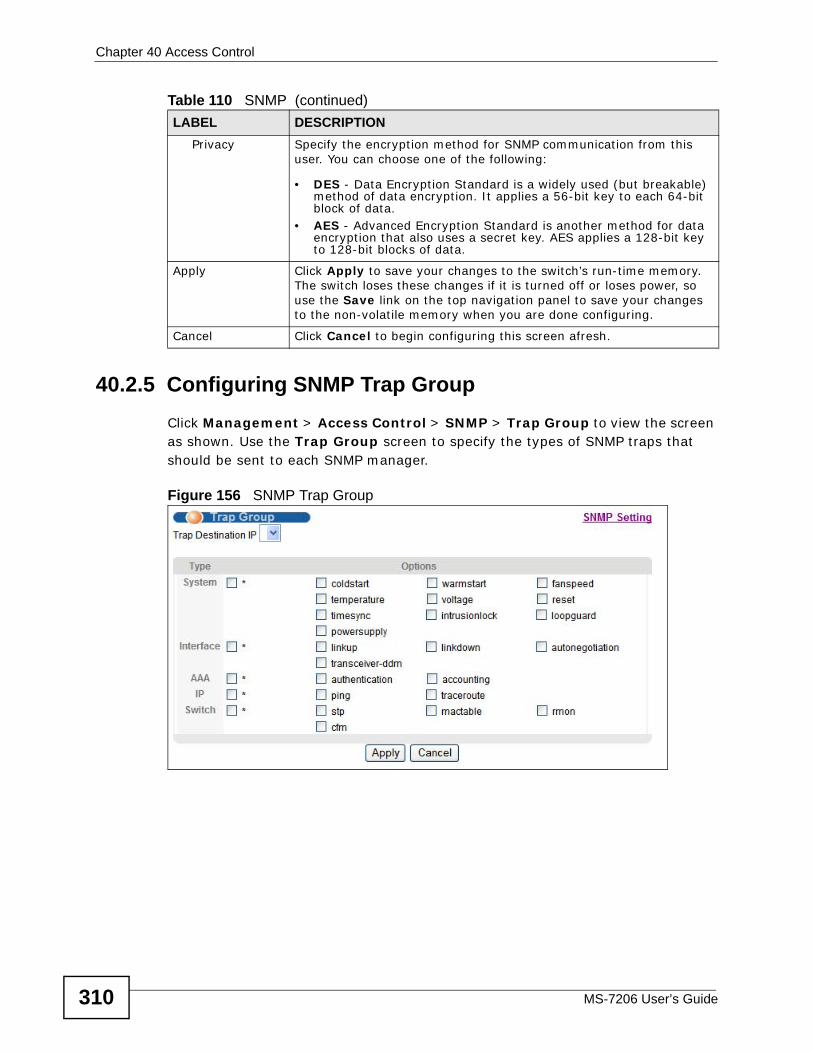
Chapter 40 Access Control
MS-7206 User’s Guide310
40.2.5 Configuring SNMP Trap Group Click Management > Access Control > SNMP > Trap Group to view the screen as shown. Use the Trap Group screen to specify the types of SNMP traps that should be sent to each SNMP manager.
Figure 156 SNMP Trap Group
Privacy Specify the encryption method for SNMP communication from this user. You can choose one of the following:
• DES - Data Encryption Standard is a widely used (but breakable) method of data encryption. It applies a 56-bit key to each 64-bit block of data.
• AES - Advanced Encryption Standard is another method for data encryption that also uses a secret key. AES applies a 128-bit key to 128-bit blocks of data.
Apply Click Apply to save your changes to the switch’s run-time memory. The switch loses these changes if it is turned off or loses power, so use the Save link on the top navigation panel to save your changes to the non-volatile memory when you are done configuring.
Cancel Click Cancel to begin configuring this screen afresh.
Table 110 SNMP (continued)LABEL DESCRIPTION
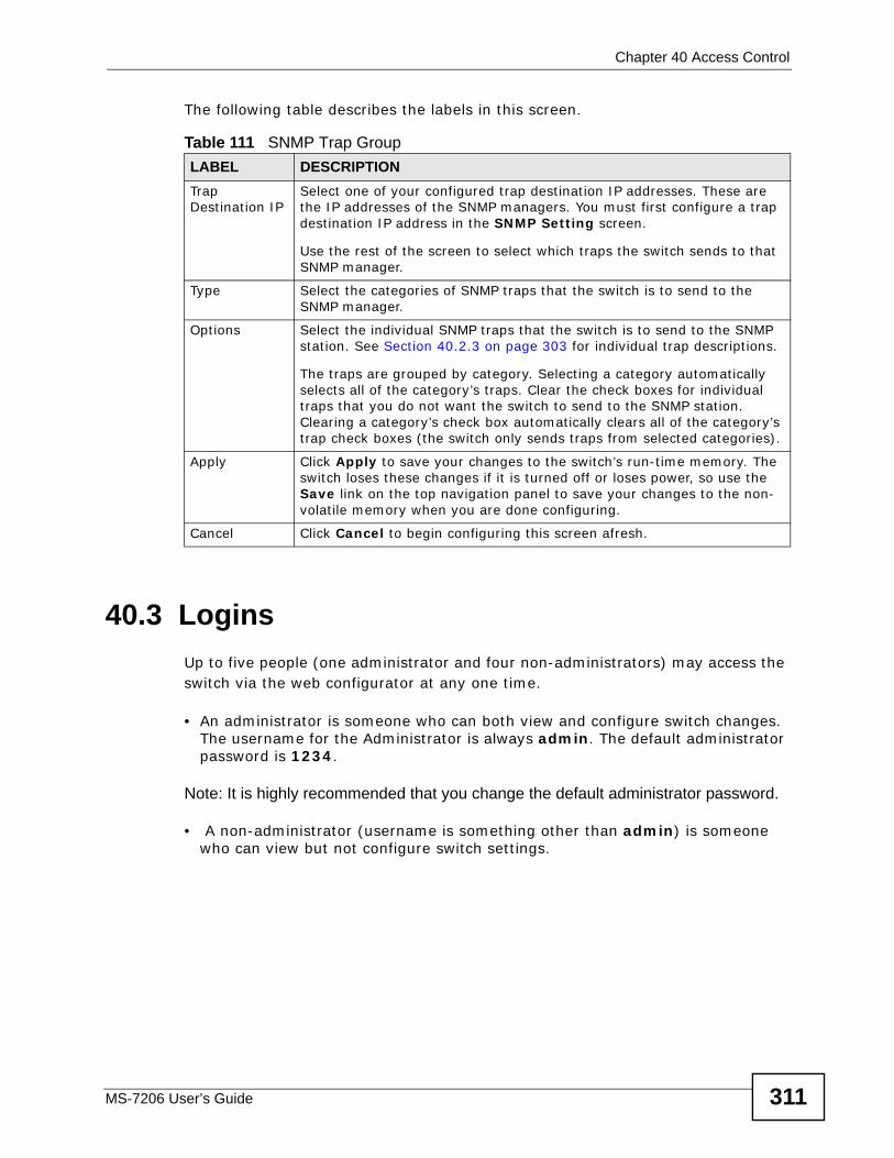
Chapter 40 Access Control
MS-7206 User’s Guide 311
The following table describes the labels in this screen.
40.3 LoginsUp to five people (one administrator and four non-administrators) may access the switch via the web configurator at any one time.
• An administrator is someone who can both view and configure switch changes. The username for the Administrator is always admin. The default administrator password is 1234.
Note: It is highly recommended that you change the default administrator password.
• A non-administrator (username is something other than admin) is someone who can view but not configure switch settings.
Table 111 SNMP Trap Group LABEL DESCRIPTIONTrap Destination IP
Select one of your configured trap destination IP addresses. These are the IP addresses of the SNMP managers. You must first configure a trap destination IP address in the SNMP Setting screen.
Use the rest of the screen to select which traps the switch sends to that SNMP manager.
Type Select the categories of SNMP traps that the switch is to send to the SNMP manager.
Options Select the individual SNMP traps that the switch is to send to the SNMP station. See Section 40.2.3 on page 303 for individual trap descriptions.
The traps are grouped by category. Selecting a category automatically selects all of the category’s traps. Clear the check boxes for individual traps that you do not want the switch to send to the SNMP station. Clearing a category’s check box automatically clears all of the category’s trap check boxes (the switch only sends traps from selected categories).
Apply Click Apply to save your changes to the switch’s run-time memory. The switch loses these changes if it is turned off or loses power, so use the Save link on the top navigation panel to save your changes to the non-volatile memory when you are done configuring.
Cancel Click Cancel to begin configuring this screen afresh.
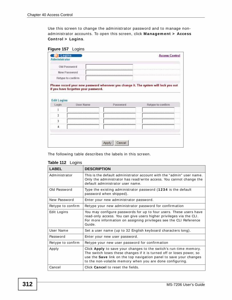
Chapter 40 Access Control
MS-7206 User’s Guide312
Use this screen to change the administrator password and to manage non-administrator accounts. To open this screen, click Management > Access Control > Logins.
Figure 157 Logins
The following table describes the labels in this screen.
Table 112 LoginsLABEL DESCRIPTIONAdministrator This is the default administrator account with the “admin” user name.
Only the administrator has read/write access. You cannot change the default administrator user name.
Old Password Type the existing administrator password (1234 is the default password when shipped).
New Password Enter your new administrator password.
Retype to confirm Retype your new administrator password for confirmation
Edit Logins You may configure passwords for up to four users. These users have read-only access. You can give users higher privileges via the CLI. For more information on assigning privileges see the CLI Reference Guide.
User Name Set a user name (up to 32 English keyboard characters long).
Password Enter your new user password.
Retype to confirm Retype your new user password for confirmation
Apply Click Apply to save your changes to the switch’s run-time memory. The switch loses these changes if it is turned off or loses power, so use the Save link on the top navigation panel to save your changes to the non-volatile memory when you are done configuring.
Cancel Click Cancel to reset the fields.
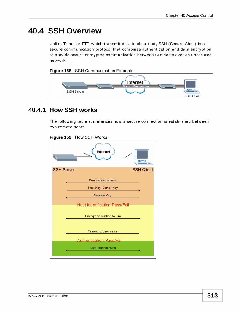
Chapter 40 Access Control
MS-7206 User’s Guide 313
40.4 SSH OverviewUnlike Telnet or FTP, which transmit data in clear text, SSH (Secure Shell) is a secure communication protocol that combines authentication and data encryption to provide secure encrypted communication between two hosts over an unsecured network.
Figure 158 SSH Communication Example
40.4.1 How SSH worksThe following table summarizes how a secure connection is established between two remote hosts.
Figure 159 How SSH Works
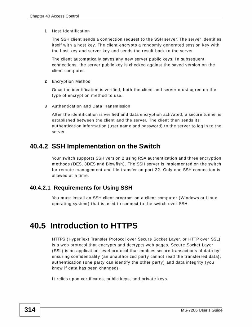
Chapter 40 Access Control
MS-7206 User’s Guide314
1 Host Identification
The SSH client sends a connection request to the SSH server. The server identifies itself with a host key. The client encrypts a randomly generated session key with the host key and server key and sends the result back to the server.
The client automatically saves any new server public keys. In subsequent connections, the server public key is checked against the saved version on the client computer.
2 Encryption Method
Once the identification is verified, both the client and server must agree on the type of encryption method to use.
3 Authentication and Data Transmission
After the identification is verified and data encryption activated, a secure tunnel is established between the client and the server. The client then sends its authentication information (user name and password) to the server to log in to the server.
40.4.2 SSH Implementation on the SwitchYour switch supports SSH version 2 using RSA authentication and three encryption methods (DES, 3DES and Blowfish). The SSH server is implemented on the switch for remote management and file transfer on port 22. Only one SSH connection is allowed at a time.
40.4.2.1 Requirements for Using SSHYou must install an SSH client program on a client computer (Windows or Linux operating system) that is used to connect to the switch over SSH.
40.5 Introduction to HTTPSHTTPS (HyperText Transfer Protocol over Secure Socket Layer, or HTTP over SSL) is a web protocol that encrypts and decrypts web pages. Secure Socket Layer (SSL) is an application-level protocol that enables secure transactions of data by ensuring confidentiality (an unauthorized party cannot read the transferred data), authentication (one party can identify the other party) and data integrity (you know if data has been changed).
It relies upon certificates, public keys, and private keys.
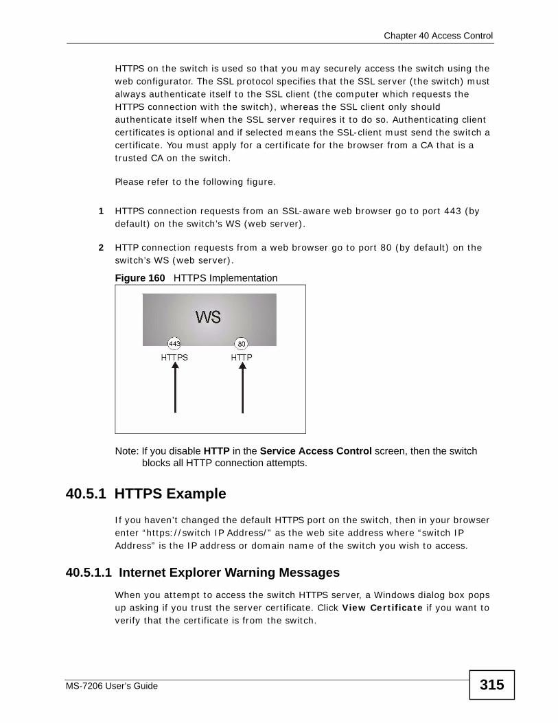
Chapter 40 Access Control
MS-7206 User’s Guide 315
HTTPS on the switch is used so that you may securely access the switch using the web configurator. The SSL protocol specifies that the SSL server (the switch) must always authenticate itself to the SSL client (the computer which requests the HTTPS connection with the switch), whereas the SSL client only should authenticate itself when the SSL server requires it to do so. Authenticating client certificates is optional and if selected means the SSL-client must send the switch a certificate. You must apply for a certificate for the browser from a CA that is a trusted CA on the switch.
Please refer to the following figure.
1 HTTPS connection requests from an SSL-aware web browser go to port 443 (by default) on the switch’s WS (web server).
2 HTTP connection requests from a web browser go to port 80 (by default) on the switch’s WS (web server).
Figure 160 HTTPS Implementation
Note: If you disable HTTP in the Service Access Control screen, then the switch blocks all HTTP connection attempts.
40.5.1 HTTPS ExampleIf you haven’t changed the default HTTPS port on the switch, then in your browser enter “https://switch IP Address/” as the web site address where “switch IP Address” is the IP address or domain name of the switch you wish to access.
40.5.1.1 Internet Explorer Warning MessagesWhen you attempt to access the switch HTTPS server, a Windows dialog box pops up asking if you trust the server certificate. Click View Certificate if you want to verify that the certificate is from the switch.
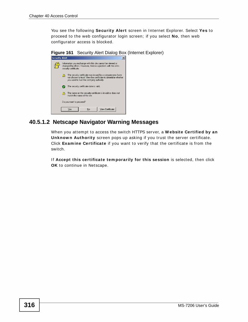
Chapter 40 Access Control
MS-7206 User’s Guide316
You see the following Security Alert screen in Internet Explorer. Select Yes to proceed to the web configurator login screen; if you select No, then web configurator access is blocked.
Figure 161 Security Alert Dialog Box (Internet Explorer)
40.5.1.2 Netscape Navigator Warning MessagesWhen you attempt to access the switch HTTPS server, a Website Certified by an Unknown Authority screen pops up asking if you trust the server certificate. Click Examine Certificate if you want to verify that the certificate is from the switch.
If Accept this certificate temporarily for this session is selected, then click OK to continue in Netscape.
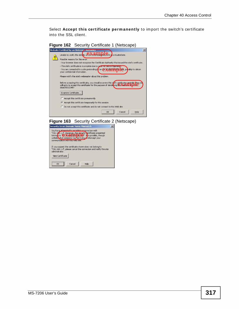
Chapter 40 Access Control
MS-7206 User’s Guide 317
Select Accept this certificate permanently to import the switch’s certificate into the SSL client.
Figure 162 Security Certificate 1 (Netscape)
Figure 163 Security Certificate 2 (Netscape)
example
example
example
example
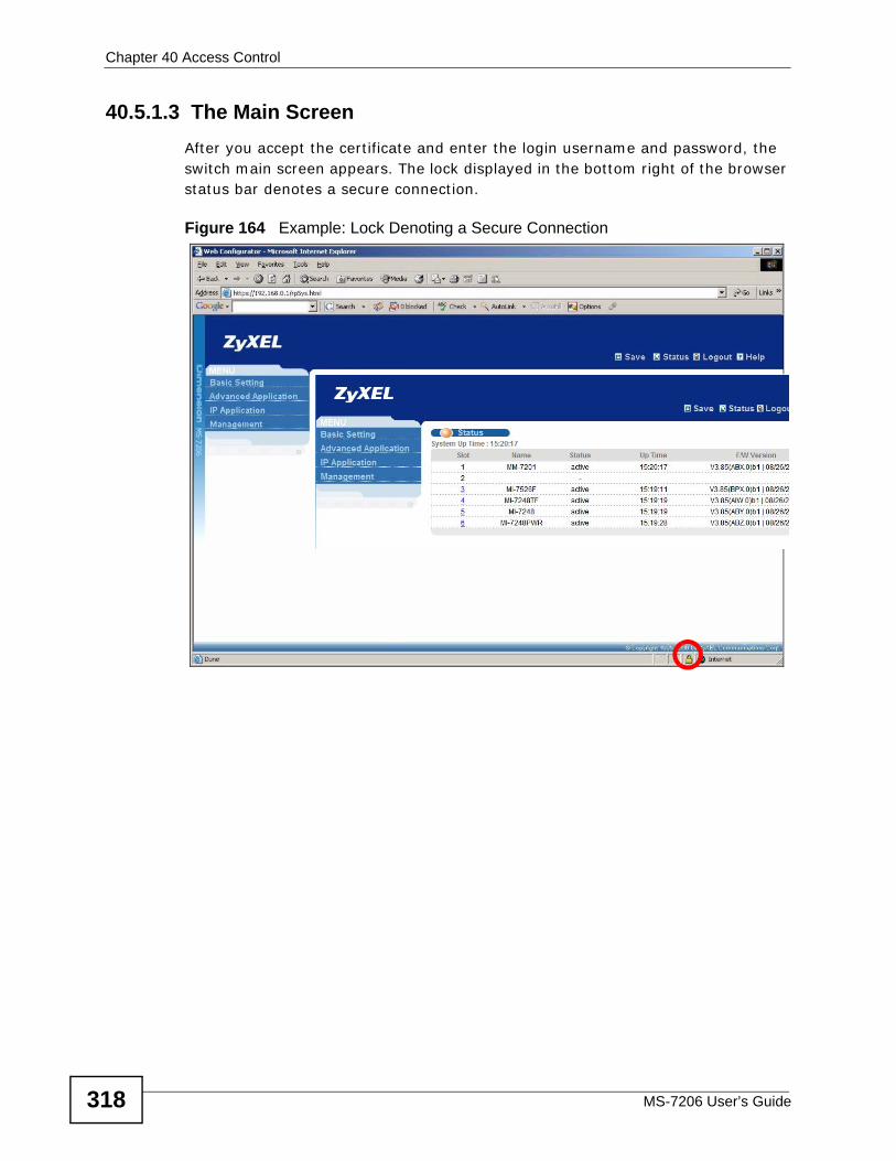
Chapter 40 Access Control
MS-7206 User’s Guide318
40.5.1.3 The Main ScreenAfter you accept the certificate and enter the login username and password, the switch main screen appears. The lock displayed in the bottom right of the browser status bar denotes a secure connection.
Figure 164 Example: Lock Denoting a Secure Connection
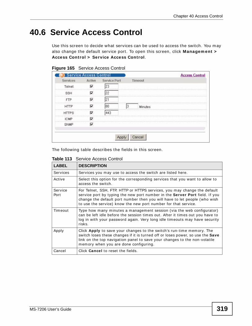
Chapter 40 Access Control
MS-7206 User’s Guide 319
40.6 Service Access ControlUse this screen to decide what services can be used to access the switch. You may also change the default service port. To open this screen, click Management > Access Control > Service Access Control.
Figure 165 Service Access Control
The following table describes the fields in this screen.
Table 113 Service Access Control LABEL DESCRIPTIONServices Services you may use to access the switch are listed here.
Active Select this option for the corresponding services that you want to allow to access the switch.
Service Port
For Telnet, SSH, FTP, HTTP or HTTPS services, you may change the default service port by typing the new port number in the Server Port field. If you change the default port number then you will have to let people (who wish to use the service) know the new port number for that service.
Timeout Type how many minutes a management session (via the web configurator) can be left idle before the session times out. After it times out you have to log in with your password again. Very long idle timeouts may have security risks.
Apply Click Apply to save your changes to the switch’s run-time memory. The switch loses these changes if it is turned off or loses power, so use the Save link on the top navigation panel to save your changes to the non-volatile memory when you are done configuring.
Cancel Click Cancel to reset the fields.
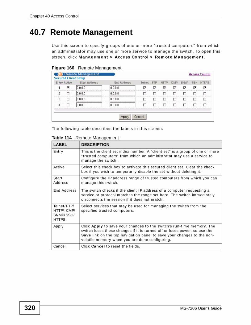
Chapter 40 Access Control
MS-7206 User’s Guide320
40.7 Remote Management Use this screen to specify groups of one or more “trusted computers” from which an administrator may use one or more service to manage the switch. To open this screen, click Management > Access Control > Remote Management.
Figure 166 Remote Management
The following table describes the labels in this screen.
Table 114 Remote ManagementLABEL DESCRIPTIONEntry This is the client set index number. A “client set” is a group of one or more
“trusted computers” from which an administrator may use a service to manage the switch.
Active Select this check box to activate this secured client set. Clear the check box if you wish to temporarily disable the set without deleting it.
Start Address
End Address
Configure the IP address range of trusted computers from which you can manage this switch.
The switch checks if the client IP address of a computer requesting a service or protocol matches the range set here. The switch immediately disconnects the session if it does not match.
Telnet/FTP/HTTP/ICMP/SNMP/SSH/HTTPS
Select services that may be used for managing the switch from the specified trusted computers.
Apply Click Apply to save your changes to the switch’s run-time memory. The switch loses these changes if it is turned off or loses power, so use the Save link on the top navigation panel to save your changes to the non-volatile memory when you are done configuring.
Cancel Click Cancel to reset the fields.
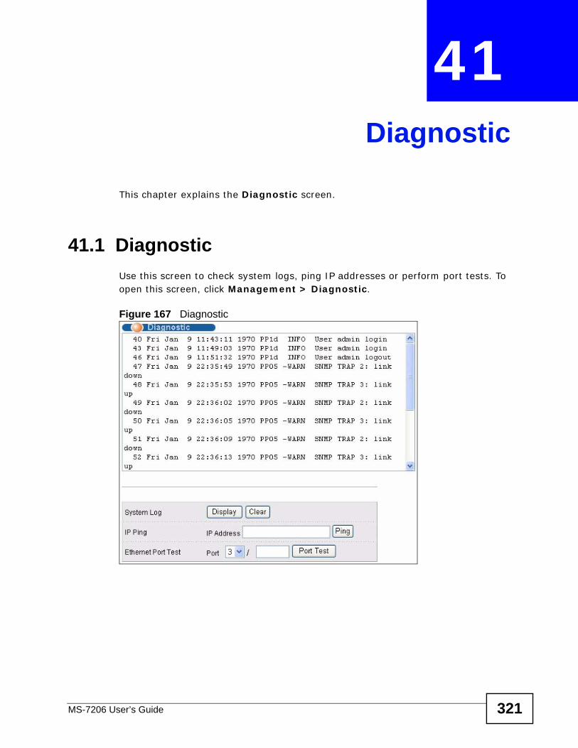
MS-7206 User’s Guide 321
CHAPTER 41 Diagnostic
This chapter explains the Diagnostic screen.
41.1 Diagnostic Use this screen to check system logs, ping IP addresses or perform port tests. To open this screen, click Management > Diagnostic.
Figure 167 Diagnostic
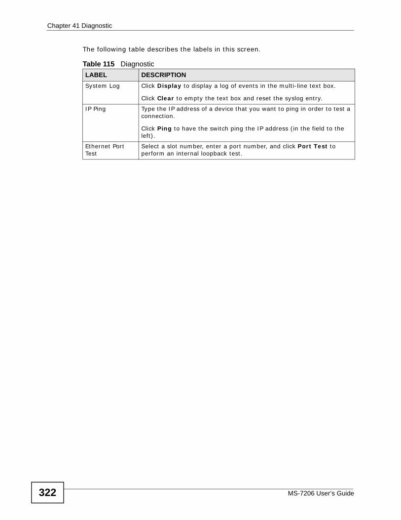
Chapter 41 Diagnostic
MS-7206 User’s Guide322
The following table describes the labels in this screen.
Table 115 DiagnosticLABEL DESCRIPTIONSystem Log Click Display to display a log of events in the multi-line text box.
Click Clear to empty the text box and reset the syslog entry.
IP Ping Type the IP address of a device that you want to ping in order to test a connection.
Click Ping to have the switch ping the IP address (in the field to the left).
Ethernet Port Test
Select a slot number, enter a port number, and click Port Test to perform an internal loopback test.
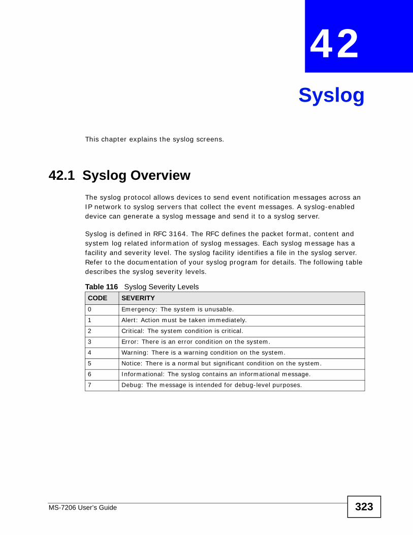
MS-7206 User’s Guide 323
CHAPTER 42 Syslog
This chapter explains the syslog screens.
42.1 Syslog OverviewThe syslog protocol allows devices to send event notification messages across an IP network to syslog servers that collect the event messages. A syslog-enabled device can generate a syslog message and send it to a syslog server.
Syslog is defined in RFC 3164. The RFC defines the packet format, content and system log related information of syslog messages. Each syslog message has a facility and severity level. The syslog facility identifies a file in the syslog server. Refer to the documentation of your syslog program for details. The following table describes the syslog severity levels.
Table 116 Syslog Severity LevelsCODE SEVERITY0 Emergency: The system is unusable.
1 Alert: Action must be taken immediately.
2 Critical: The system condition is critical.
3 Error: There is an error condition on the system.
4 Warning: There is a warning condition on the system.
5 Notice: There is a normal but significant condition on the system.
6 Informational: The syslog contains an informational message.
7 Debug: The message is intended for debug-level purposes.
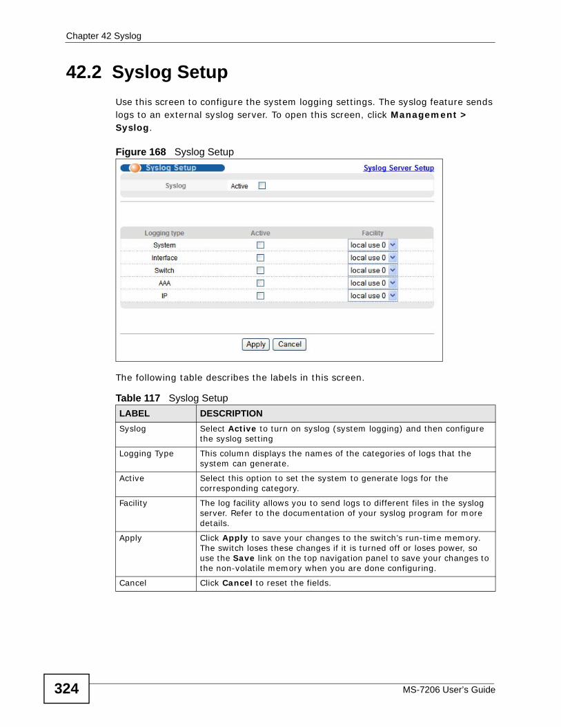
Chapter 42 Syslog
MS-7206 User’s Guide324
42.2 Syslog SetupUse this screen to configure the system logging settings. The syslog feature sends logs to an external syslog server. To open this screen, click Management > Syslog.
Figure 168 Syslog Setup
The following table describes the labels in this screen.
Table 117 Syslog SetupLABEL DESCRIPTIONSyslog Select Active to turn on syslog (system logging) and then configure
the syslog setting
Logging Type This column displays the names of the categories of logs that the system can generate.
Active Select this option to set the system to generate logs for the corresponding category.
Facility The log facility allows you to send logs to different files in the syslog server. Refer to the documentation of your syslog program for more details.
Apply Click Apply to save your changes to the switch’s run-time memory. The switch loses these changes if it is turned off or loses power, so use the Save link on the top navigation panel to save your changes to the non-volatile memory when you are done configuring.
Cancel Click Cancel to reset the fields.
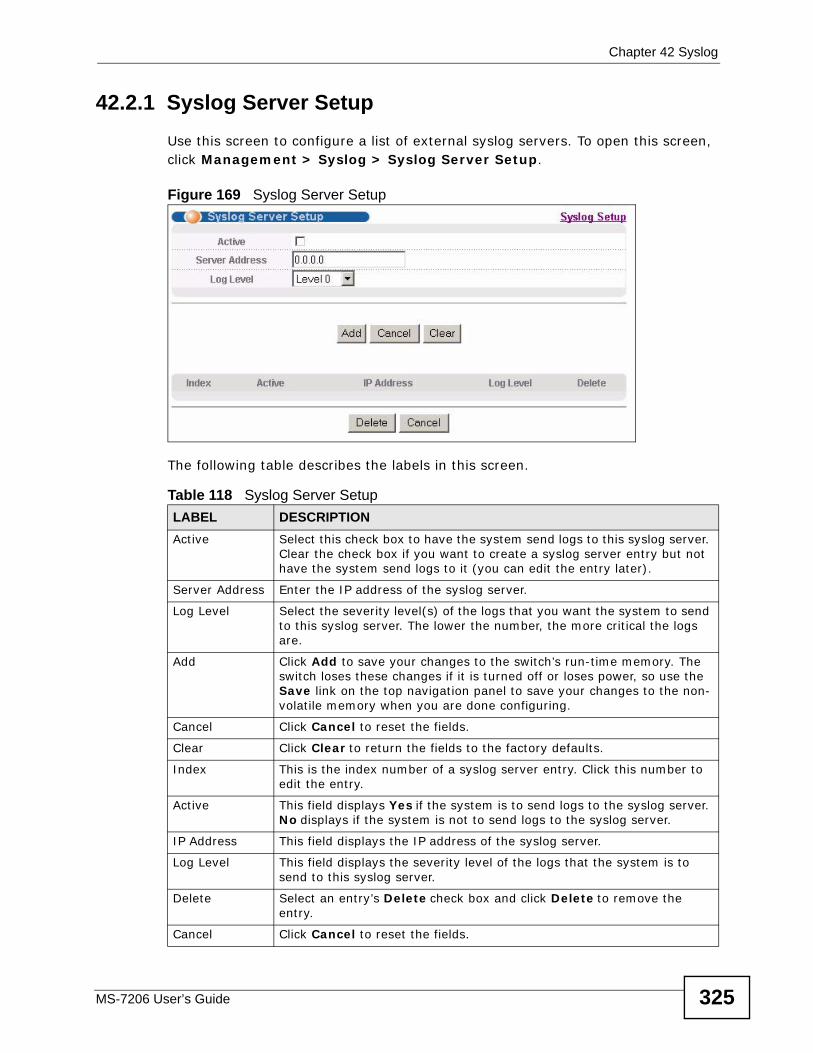
Chapter 42 Syslog
MS-7206 User’s Guide 325
42.2.1 Syslog Server Setup Use this screen to configure a list of external syslog servers. To open this screen, click Management > Syslog > Syslog Server Setup.
Figure 169 Syslog Server Setup
The following table describes the labels in this screen.
Table 118 Syslog Server Setup LABEL DESCRIPTIONActive Select this check box to have the system send logs to this syslog server.
Clear the check box if you want to create a syslog server entry but not have the system send logs to it (you can edit the entry later).
Server Address Enter the IP address of the syslog server.
Log Level Select the severity level(s) of the logs that you want the system to send to this syslog server. The lower the number, the more critical the logs are.
Add Click Add to save your changes to the switch’s run-time memory. The switch loses these changes if it is turned off or loses power, so use the Save link on the top navigation panel to save your changes to the non-volatile memory when you are done configuring.
Cancel Click Cancel to reset the fields.
Clear Click Clear to return the fields to the factory defaults.
Index This is the index number of a syslog server entry. Click this number to edit the entry.
Active This field displays Yes if the system is to send logs to the syslog server. No displays if the system is not to send logs to the syslog server.
IP Address This field displays the IP address of the syslog server.
Log Level This field displays the severity level of the logs that the system is to send to this syslog server.
Delete Select an entry’s Delete check box and click Delete to remove the entry.
Cancel Click Cancel to reset the fields.

Chapter 42 Syslog
MS-7206 User’s Guide326
MS-7206 User’s Guide 327
CHAPTER 43 Cluster Management
This chapter introduces cluster management.
43.1 Cluster Management Status OverviewCluster Management allows you to manage switches through one switch, called the cluster manager. The switches must be directly connected and be in the same VLAN group so as to be able to communicate with one another.
Table 119 Cluster Management SpecificationsCluster Member Models Must be compatible with ZyXEL cluster management
implementation.
Cluster Manager The switch through which you manage the cluster member switches.
Cluster Members The switches being managed by the cluster manager switch.
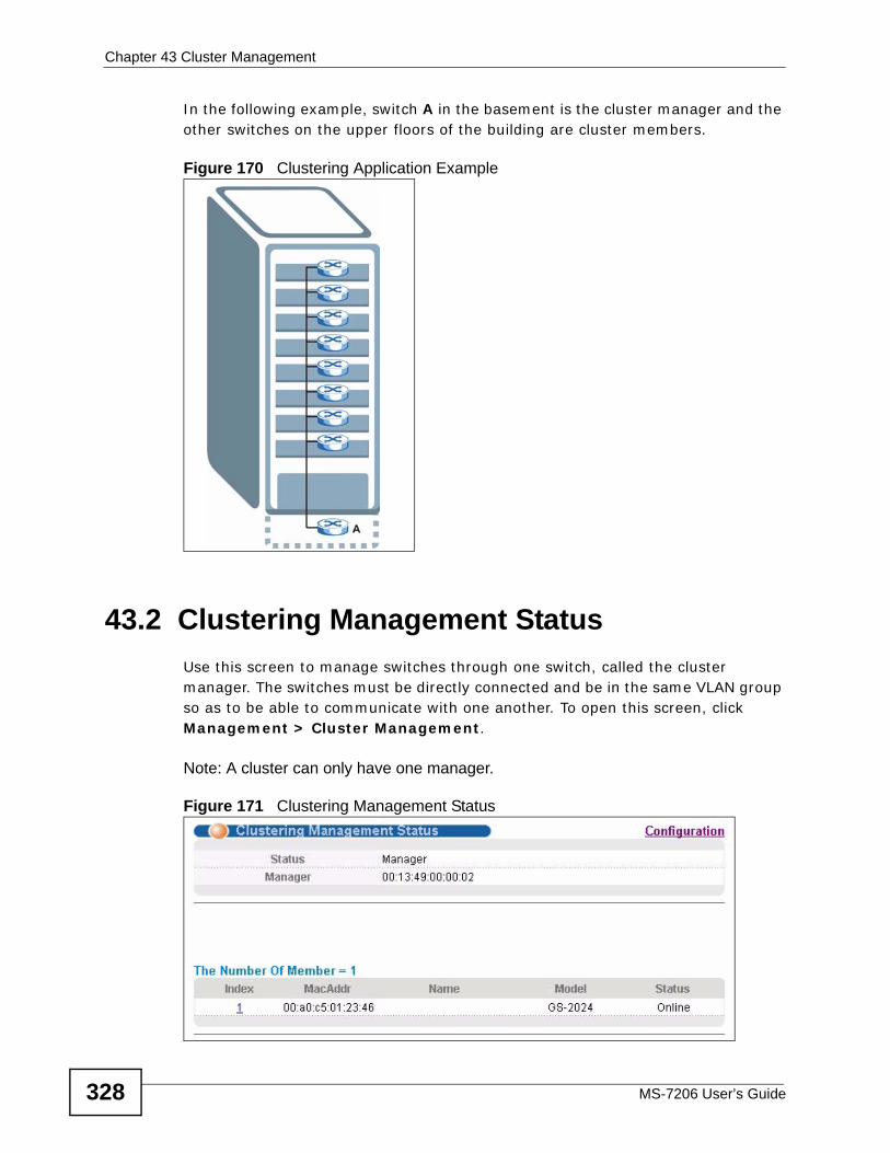
Chapter 43 Cluster Management
MS-7206 User’s Guide328
In the following example, switch A in the basement is the cluster manager and the other switches on the upper floors of the building are cluster members.
Figure 170 Clustering Application Example
43.2 Clustering Management StatusUse this screen to manage switches through one switch, called the cluster manager. The switches must be directly connected and be in the same VLAN group so as to be able to communicate with one another. To open this screen, click Management > Cluster Management.
Note: A cluster can only have one manager.
Figure 171 Clustering Management Status
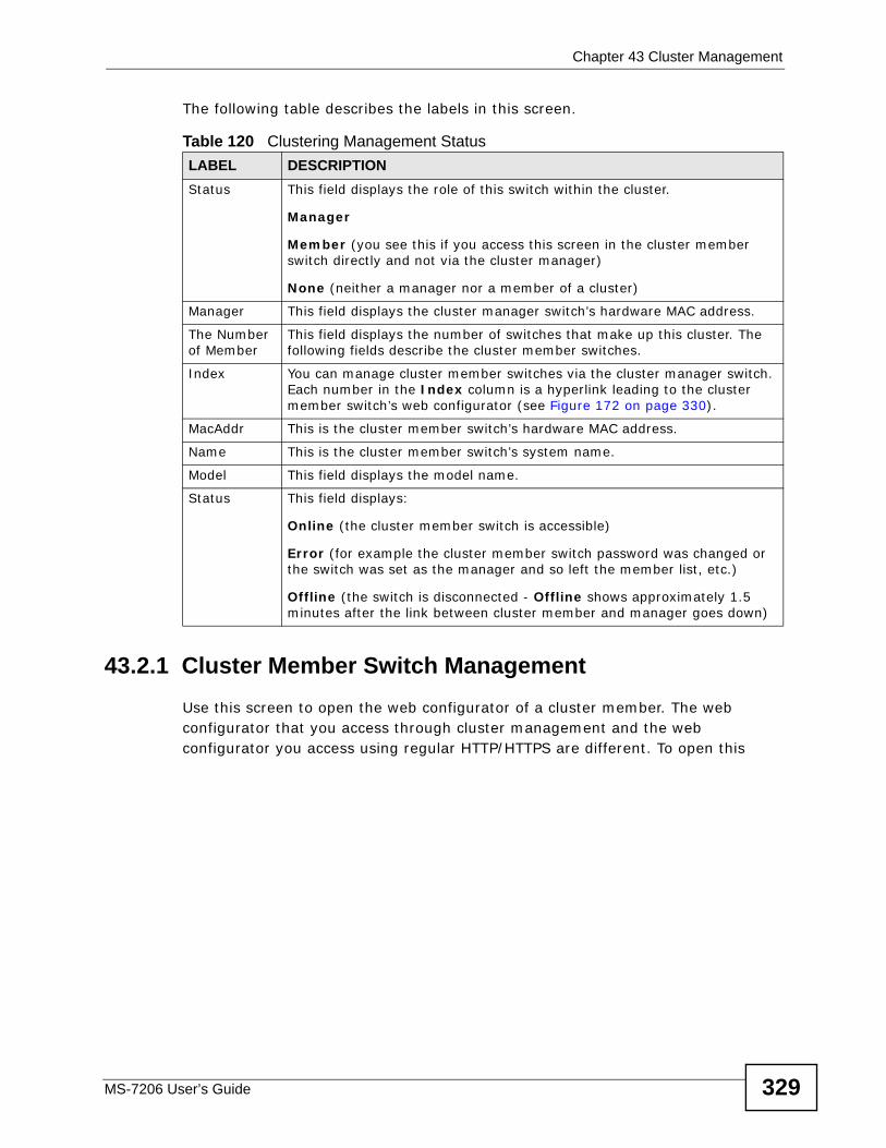
Chapter 43 Cluster Management
MS-7206 User’s Guide 329
The following table describes the labels in this screen.
43.2.1 Cluster Member Switch Management Use this screen to open the web configurator of a cluster member. The web configurator that you access through cluster management and the web configurator you access using regular HTTP/HTTPS are different. To open this
Table 120 Clustering Management StatusLABEL DESCRIPTIONStatus This field displays the role of this switch within the cluster.
Manager
Member (you see this if you access this screen in the cluster member switch directly and not via the cluster manager)
None (neither a manager nor a member of a cluster)
Manager This field displays the cluster manager switch’s hardware MAC address.
The Number of Member
This field displays the number of switches that make up this cluster. The following fields describe the cluster member switches.
Index You can manage cluster member switches via the cluster manager switch. Each number in the Index column is a hyperlink leading to the cluster member switch’s web configurator (see Figure 172 on page 330).
MacAddr This is the cluster member switch’s hardware MAC address.
Name This is the cluster member switch’s system name.
Model This field displays the model name.
Status This field displays:
Online (the cluster member switch is accessible)
Error (for example the cluster member switch password was changed or the switch was set as the manager and so left the member list, etc.)
Offline (the switch is disconnected - Offline shows approximately 1.5 minutes after the link between cluster member and manager goes down)
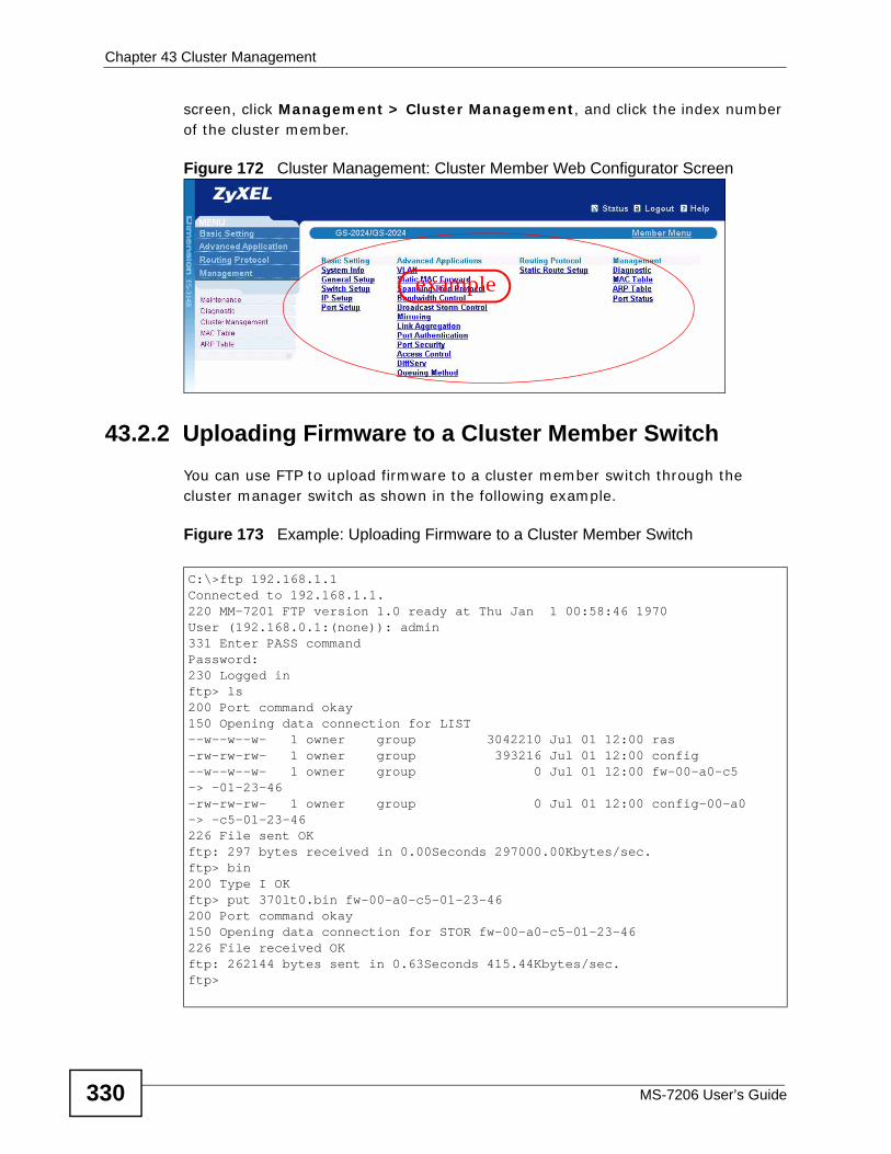
Chapter 43 Cluster Management
MS-7206 User’s Guide330
screen, click Management > Cluster Management, and click the index number of the cluster member.
Figure 172 Cluster Management: Cluster Member Web Configurator Screen
43.2.2 Uploading Firmware to a Cluster Member Switch You can use FTP to upload firmware to a cluster member switch through the cluster manager switch as shown in the following example.
Figure 173 Example: Uploading Firmware to a Cluster Member Switch
example
C:\>ftp 192.168.1.1Connected to 192.168.1.1.220 MM-7201 FTP version 1.0 ready at Thu Jan 1 00:58:46 1970User (192.168.0.1:(none)): admin331 Enter PASS commandPassword:230 Logged inftp> ls200 Port command okay150 Opening data connection for LIST--w--w--w- 1 owner group 3042210 Jul 01 12:00 ras-rw-rw-rw- 1 owner group 393216 Jul 01 12:00 config--w--w--w- 1 owner group 0 Jul 01 12:00 fw-00-a0-c5-> -01-23-46-rw-rw-rw- 1 owner group 0 Jul 01 12:00 config-00-a0-> -c5-01-23-46226 File sent OKftp: 297 bytes received in 0.00Seconds 297000.00Kbytes/sec.ftp> bin200 Type I OKftp> put 370lt0.bin fw-00-a0-c5-01-23-46200 Port command okay150 Opening data connection for STOR fw-00-a0-c5-01-23-46226 File received OKftp: 262144 bytes sent in 0.63Seconds 415.44Kbytes/sec.ftp>
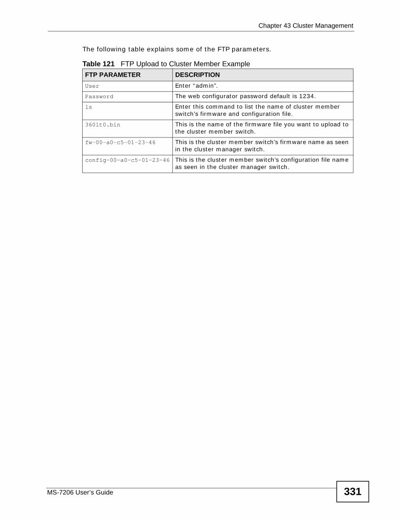
Chapter 43 Cluster Management
MS-7206 User’s Guide 331
The following table explains some of the FTP parameters.
Table 121 FTP Upload to Cluster Member Example FTP PARAMETER DESCRIPTIONUser Enter “admin”.
Password The web configurator password default is 1234.
ls Enter this command to list the name of cluster member switch’s firmware and configuration file.
360lt0.bin This is the name of the firmware file you want to upload to the cluster member switch.
fw-00-a0-c5-01-23-46 This is the cluster member switch’s firmware name as seen in the cluster manager switch.
config-00-a0-c5-01-23-46 This is the cluster member switch’s configuration file name as seen in the cluster manager switch.
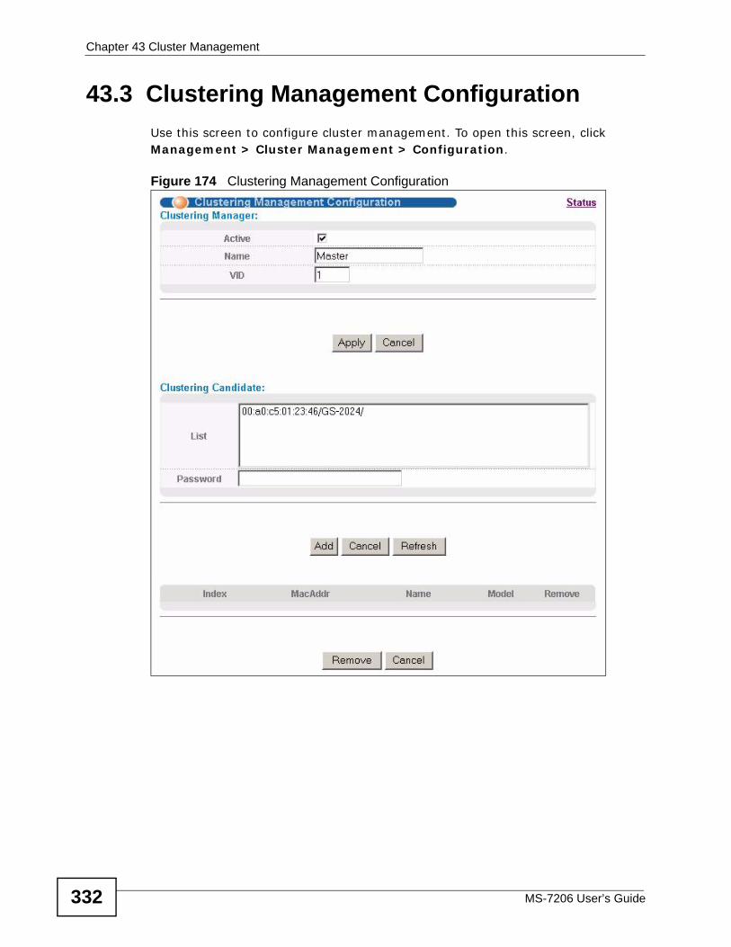
Chapter 43 Cluster Management
MS-7206 User’s Guide332
43.3 Clustering Management ConfigurationUse this screen to configure cluster management. To open this screen, click Management > Cluster Management > Configuration.
Figure 174 Clustering Management Configuration
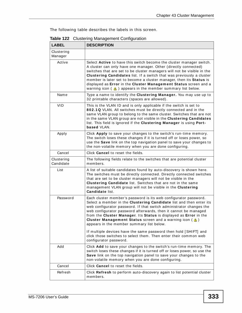
Chapter 43 Cluster Management
MS-7206 User’s Guide 333
The following table describes the labels in this screen.
Table 122 Clustering Management ConfigurationLABEL DESCRIPTIONClustering Manager
Active Select Active to have this switch become the cluster manager switch. A cluster can only have one manager. Other (directly connected) switches that are set to be cluster managers will not be visible in the Clustering Candidates list. If a switch that was previously a cluster member is later set to become a cluster manager, then its Status is displayed as Error in the Cluster Management Status screen and a warning icon ( ) appears in the member summary list below.
Name Type a name to identify the Clustering Manager. You may use up to 32 printable characters (spaces are allowed).
VID This is the VLAN ID and is only applicable if the switch is set to 802.1Q VLAN. All switches must be directly connected and in the same VLAN group to belong to the same cluster. Switches that are not in the same VLAN group are not visible in the Clustering Candidates list. This field is ignored if the Clustering Manager is using Port-based VLAN.
Apply Click Apply to save your changes to the switch’s run-time memory. The switch loses these changes if it is turned off or loses power, so use the Save link on the top navigation panel to save your changes to the non-volatile memory when you are done configuring.
Cancel Click Cancel to reset the fields.
Clustering Candidate
The following fields relate to the switches that are potential cluster members.
List A list of suitable candidates found by auto-discovery is shown here. The switches must be directly connected. Directly connected switches that are set to be cluster managers will not be visible in the Clustering Candidate list. Switches that are not in the same management VLAN group will not be visible in the Clustering Candidate list.
Password Each cluster member’s password is its web configurator password. Select a member in the Clustering Candidate list and then enter its web configurator password. If that switch administrator changes the web configurator password afterwards, then it cannot be managed from the Cluster Manager. Its Status is displayed as Error in the Cluster Management Status screen and a warning icon ( ) appears in the member summary list below.
If multiple devices have the same password then hold [SHIFT] and click those switches to select them. Then enter their common web configurator password.
Add Click Add to save your changes to the switch’s run-time memory. The switch loses these changes if it is turned off or loses power, so use the Save link on the top navigation panel to save your changes to the non-volatile memory when you are done configuring.
Cancel Click Cancel to reset the fields.
Refresh Click Refresh to perform auto-discovery again to list potential cluster members.
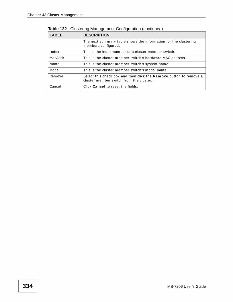
Chapter 43 Cluster Management
MS-7206 User’s Guide334
The next summary table shows the information for the clustering members configured.
Index This is the index number of a cluster member switch.
MacAddr This is the cluster member switch’s hardware MAC address.
Name This is the cluster member switch’s system name.
Model This is the cluster member switch’s model name.
Remove Select this check box and then click the Remove button to remove a cluster member switch from the cluster.
Cancel Click Cancel to reset the fields.
Table 122 Clustering Management Configuration (continued)LABEL DESCRIPTION
MS-7206 User’s Guide 335
CHAPTER 44 MAC Table
This chapter introduces the MAC table in the switch and then explains the MAC table screen.
44.1 MAC Table OverviewThe MAC Table screen (a MAC table is also known as a filtering database) shows how frames are forwarded or filtered across the switch’s ports. It shows what device MAC address, belonging to what VLAN group (if any) is forwarded to which port(s) and whether the MAC address is dynamic (learned by the switch) or static (manually entered in the Static MAC Forwarding screen, see Chapter 14 on page 101).
The switch uses the MAC table to determine how to forward frames. See the following figure.
1 The switch examines a received frame and learns the port on which this source MAC address came.
2 The switch checks to see if the frame's destination MAC address matches a source MAC address already learned in the MAC table.
• If the switch has already learned the port for this MAC address, then it forwards the frame to that port.
• If the switch has not already learned the port for this MAC address, then the frame is flooded to all ports. Too much port flooding leads to network congestion.
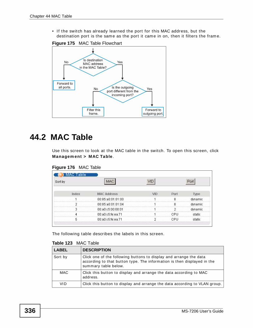
Chapter 44 MAC Table
MS-7206 User’s Guide336
• If the switch has already learned the port for this MAC address, but the destination port is the same as the port it came in on, then it filters the frame.
Figure 175 MAC Table Flowchart
44.2 MAC TableUse this screen to look at the MAC table in the switch. To open this screen, click Management > MAC Table.
Figure 176 MAC Table
The following table describes the labels in this screen.
Table 123 MAC TableLABEL DESCRIPTIONSort by Click one of the following buttons to display and arrange the data
according to that button type. The information is then displayed in the summary table below.
MAC Click this button to display and arrange the data according to MAC address.
VID Click this button to display and arrange the data according to VLAN group.
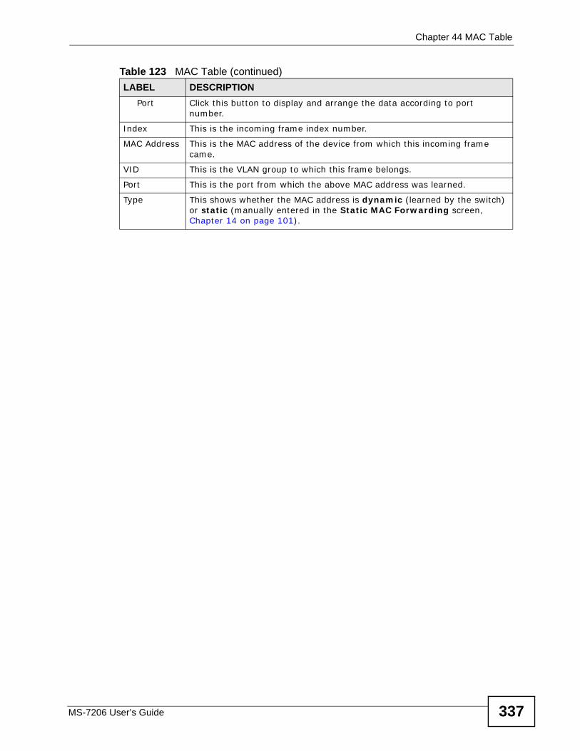
Chapter 44 MAC Table
MS-7206 User’s Guide 337
Port Click this button to display and arrange the data according to port number.
Index This is the incoming frame index number.
MAC Address This is the MAC address of the device from which this incoming frame came.
VID This is the VLAN group to which this frame belongs.
Port This is the port from which the above MAC address was learned.
Type This shows whether the MAC address is dynamic (learned by the switch) or static (manually entered in the Static MAC Forwarding screen, Chapter 14 on page 101).
Table 123 MAC Table (continued)LABEL DESCRIPTION

Chapter 44 MAC Table
MS-7206 User’s Guide338
MS-7206 User’s Guide 339
CHAPTER 45 IP Table
This chapter introduces the IP table in the switch and then explains the IP table screen.
45.1 IP Table OverviewThe IP Table screen shows how packets are forwarded or filtered across the switch’s ports. It shows what device IP address, belonging to what VLAN group (if any) is forwarded to which port(s) and whether the IP address is dynamic (learned by the switch) or static (belonging to the switch).
The switch uses the IP table to determine how to forward packets. See the following figure.
1 The switch examines a received packet and learns the port on which this source IP address came.
2 The switch checks to see if the packet's destination IP address matches a source IP address already learned in the IP table.
• If the switch has already learned the port for this IP address, then it forwards the packet to that port.
• If the switch has not already learned the port for this IP address, then the packet is flooded to all ports. Too much port flooding leads to network congestion.
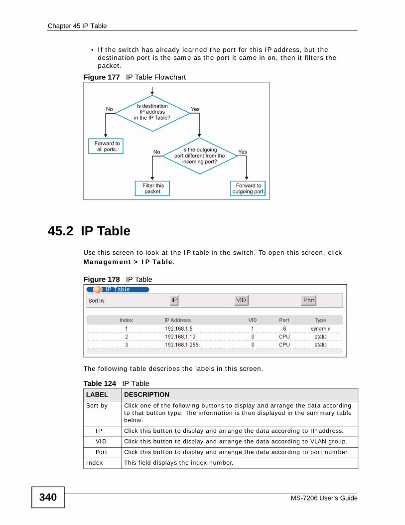
Chapter 45 IP Table
MS-7206 User’s Guide340
• If the switch has already learned the port for this IP address, but the destination port is the same as the port it came in on, then it filters the packet.
Figure 177 IP Table Flowchart
45.2 IP TableUse this screen to look at the IP table in the switch. To open this screen, click Management > IP Table.
Figure 178 IP Table
The following table describes the labels in this screen.
Table 124 IP TableLABEL DESCRIPTIONSort by Click one of the following buttons to display and arrange the data according
to that button type. The information is then displayed in the summary table below.
IP Click this button to display and arrange the data according to IP address.
VID Click this button to display and arrange the data according to VLAN group.
Port Click this button to display and arrange the data according to port number.
Index This field displays the index number.
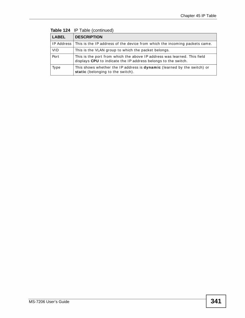
Chapter 45 IP Table
MS-7206 User’s Guide 341
IP Address This is the IP address of the device from which the incoming packets came.
VID This is the VLAN group to which the packet belongs.
Port This is the port from which the above IP address was learned. This field displays CPU to indicate the IP address belongs to the switch.
Type This shows whether the IP address is dynamic (learned by the switch) or static (belonging to the switch).
Table 124 IP Table (continued)LABEL DESCRIPTION

Chapter 45 IP Table
MS-7206 User’s Guide342
MS-7206 User’s Guide 343
CHAPTER 46 ARP Table
This chapter introduces the ARP table in the switch and then explains the ARP table screen.
46.1 ARP Table Overview Address Resolution Protocol (ARP) is a protocol for mapping an Internet Protocol address (IP address) to a physical machine address, also known as a Media Access Control or MAC address, on the local area network.
An IP (version 4) address is 32 bits long. In an Ethernet LAN, MAC addresses are 48 bits long. The ARP Table maintains an association between each MAC address and its corresponding IP address.
46.1.1 How ARP WorksWhen an incoming packet destined for a host device on a local area network arrives at the switch, the switch's ARP program looks in the ARP Table and, if it finds the address, sends it to the device.
If no entry is found for the IP address, ARP broadcasts the request to all the devices on the LAN. The switch fills in its own MAC and IP address in the sender address fields, and puts the known IP address of the target in the target IP address field. In addition, the switch puts all ones in the target MAC field (FF.FF.FF.FF.FF.FF is the Ethernet broadcast address). The replying device (which is either the IP address of the device being sought or the router that knows the way) replaces the broadcast address with the target's MAC address, swaps the sender and target pairs, and unicasts the answer directly back to the requesting machine. ARP updates the ARP Table for future reference and then sends the packet to the MAC address that replied.
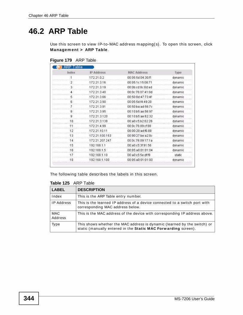
Chapter 46 ARP Table
MS-7206 User’s Guide344
46.2 ARP TableUse this screen to view IP-to-MAC address mapping(s). To open this screen, click Management > ARP Table.
Figure 179 ARP Table
The following table describes the labels in this screen.
Table 125 ARP TableLABEL DESCRIPTIONIndex This is the ARP Table entry number.
IP Address This is the learned IP address of a device connected to a switch port with corresponding MAC address below.
MAC Address
This is the MAC address of the device with corresponding IP address above.
Type This shows whether the MAC address is dynamic (learned by the switch) or static (manually entered in the Static MAC Forwarding screen).
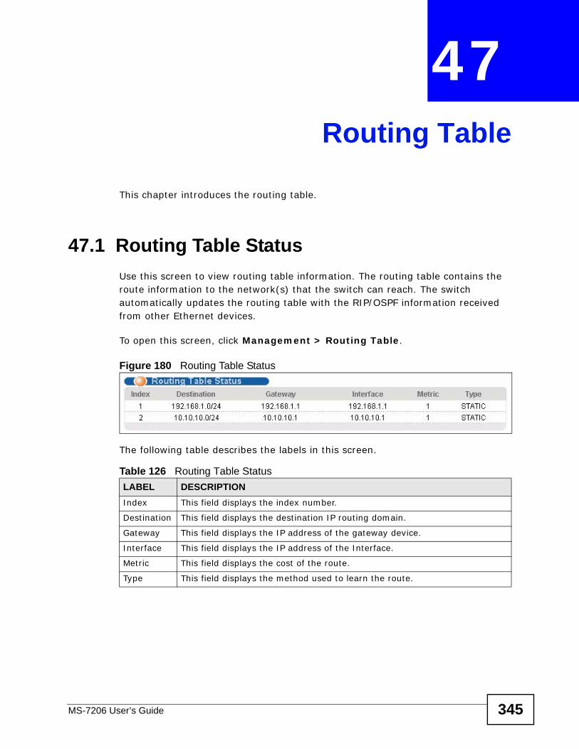
MS-7206 User’s Guide 345
CHAPTER 47 Routing Table
This chapter introduces the routing table.
47.1 Routing Table StatusUse this screen to view routing table information. The routing table contains the route information to the network(s) that the switch can reach. The switch automatically updates the routing table with the RIP/OSPF information received from other Ethernet devices.
To open this screen, click Management > Routing Table.
Figure 180 Routing Table Status
The following table describes the labels in this screen.
Table 126 Routing Table StatusLABEL DESCRIPTIONIndex This field displays the index number.
Destination This field displays the destination IP routing domain.
Gateway This field displays the IP address of the gateway device.
Interface This field displays the IP address of the Interface.
Metric This field displays the cost of the route.
Type This field displays the method used to learn the route.

Chapter 47 Routing Table
MS-7206 User’s Guide346
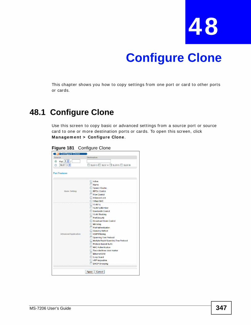
MS-7206 User’s Guide 347
CHAPTER 48 Configure Clone
This chapter shows you how to copy settings from one port or card to other ports or cards.
48.1 Configure CloneUse this screen to copy basic or advanced settings from a source port or source card to one or more destination ports or cards. To open this screen, click Management > Configure Clone.
Figure 181 Configure Clone
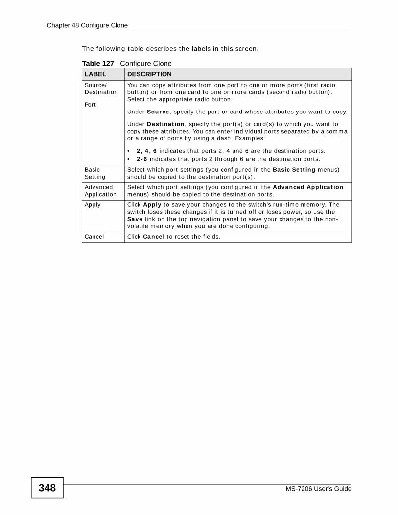
Chapter 48 Configure Clone
MS-7206 User’s Guide348
The following table describes the labels in this screen.
Table 127 Configure CloneLABEL DESCRIPTIONSource/Destination
Port
You can copy attributes from one port to one or more ports (first radio button) or from one card to one or more cards (second radio button). Select the appropriate radio button.
Under Source, specify the port or card whose attributes you want to copy.
Under Destination, specify the port(s) or card(s) to which you want to copy these attributes. You can enter individual ports separated by a comma or a range of ports by using a dash. Examples:
• 2, 4, 6 indicates that ports 2, 4 and 6 are the destination ports.• 2-6 indicates that ports 2 through 6 are the destination ports.
Basic Setting
Select which port settings (you configured in the Basic Setting menus) should be copied to the destination port(s).
Advanced Application
Select which port settings (you configured in the Advanced Application menus) should be copied to the destination ports.
Apply Click Apply to save your changes to the switch’s run-time memory. The switch loses these changes if it is turned off or loses power, so use the Save link on the top navigation panel to save your changes to the non-volatile memory when you are done configuring.
Cancel Click Cancel to reset the fields.

Chapter 48 Configure Clone
MS-7206 User’s Guide 349

Chapter 48 Configure Clone
MS-7206 User’s Guide350
351
PART VIITroubleshooting
and Product Specifications
Troubleshooting (353)
Product Specifications (357)

352
MS-7206 User’s Guide 353
CHAPTER 49 Troubleshooting
This chapter offers some suggestions to solve problems you might encounter. The potential problems are divided into the following categories.
• Power, Hardware Connections, and LEDs
• MM-7201 Access and Login
49.1 Power, Hardware Connections, and LEDs
The MM-7201 does not turn on. None of the LEDs turn on.
1 Make sure the MM-7201 is inserted correctly.
2 Make sure the MS-7206 system is receiving power. If it is not, see the appropriate User’s Guide.
3 Inspect your cables for damage. Contact the vendor to replace any damaged cables.
4 Remove and re-insert the MM-7201 into the MS-7206 chassis.
5 If the problem continues, contact the vendor.
The ALM LED is on.
1 Make sure the fans in the MS-7206 chassis are working. If they are not, see the appropriate User’s Guide.
2 Make sure the MM-7201 is operating within its operating temperature and humidity. If it is not, move the MS-7206 system to a more suitable environment.
Chapter 49 Troubleshooting
MS-7206 User’s Guide354
3 If the problem continues, contact the vendor.
49.2 MM-7201 Access and Login
I forgot the IP address for the MM-7201.
1 The default IP address is 192.168.0.1.
2 Use the console port to log in to the MM-7201.
I forgot the password.
1 The default password is 1234.
2 If this does not work, you have to reset the device to its factory defaults. See Section 4.6 on page 45.
I cannot see or access the Login screen in the web configurator.
1 Make sure you are using the correct IP address.
• The default IP address is 192.168.0.1.
• If you changed the IP address (Section 10.2 on page 74), use the new IP address.
• If you changed the IP address and have forgotten it, see the troubleshooting suggestions for I forgot the IP address for the MM-7201.
2 Make sure the MM-7201 is inserted correctly, and make sure the LEDs are behaving as expected. See Section 1.4 on page 27.
3 Make sure your Internet browser does not block pop-up windows and has JavaScripts and Java enabled.
4 Make sure your computer is in the same subnet as the MM-7201. (If you know that there are routers between your computer and the MM-7201, skip this step.)
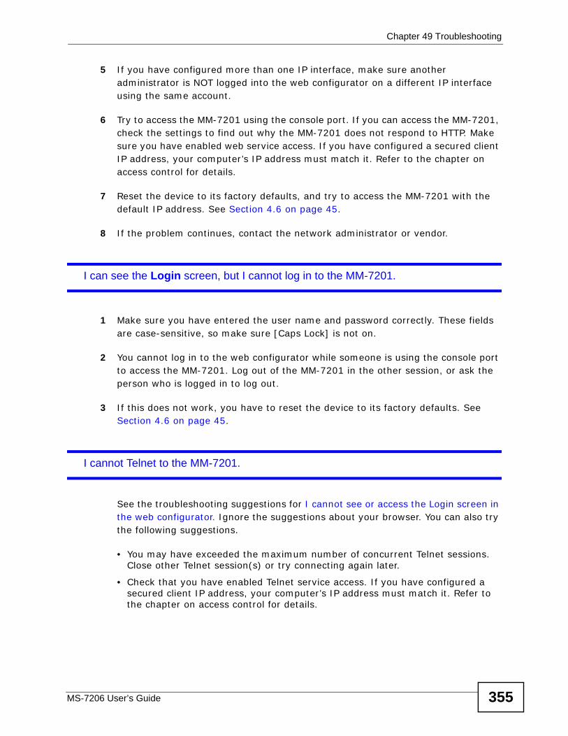
Chapter 49 Troubleshooting
MS-7206 User’s Guide 355
5 If you have configured more than one IP interface, make sure another administrator is NOT logged into the web configurator on a different IP interface using the same account.
6 Try to access the MM-7201 using the console port. If you can access the MM-7201, check the settings to find out why the MM-7201 does not respond to HTTP. Make sure you have enabled web service access. If you have configured a secured client IP address, your computer’s IP address must match it. Refer to the chapter on access control for details.
7 Reset the device to its factory defaults, and try to access the MM-7201 with the default IP address. See Section 4.6 on page 45.
8 If the problem continues, contact the network administrator or vendor.
I can see the Login screen, but I cannot log in to the MM-7201.
1 Make sure you have entered the user name and password correctly. These fields are case-sensitive, so make sure [Caps Lock] is not on.
2 You cannot log in to the web configurator while someone is using the console port to access the MM-7201. Log out of the MM-7201 in the other session, or ask the person who is logged in to log out.
3 If this does not work, you have to reset the device to its factory defaults. See Section 4.6 on page 45.
I cannot Telnet to the MM-7201.
See the troubleshooting suggestions for I cannot see or access the Login screen in the web configurator. Ignore the suggestions about your browser. You can also try the following suggestions.
• You may have exceeded the maximum number of concurrent Telnet sessions. Close other Telnet session(s) or try connecting again later.
• Check that you have enabled Telnet service access. If you have configured a secured client IP address, your computer’s IP address must match it. Refer to the chapter on access control for details.
Chapter 49 Troubleshooting
MS-7206 User’s Guide356
I cannot use FTP to upload / download the configuration file. / I cannot use FTP to upload new firmware.
See the troubleshooting suggestions for I cannot see or access the Login screen in the web configurator. Ignore the suggestions about your browser.
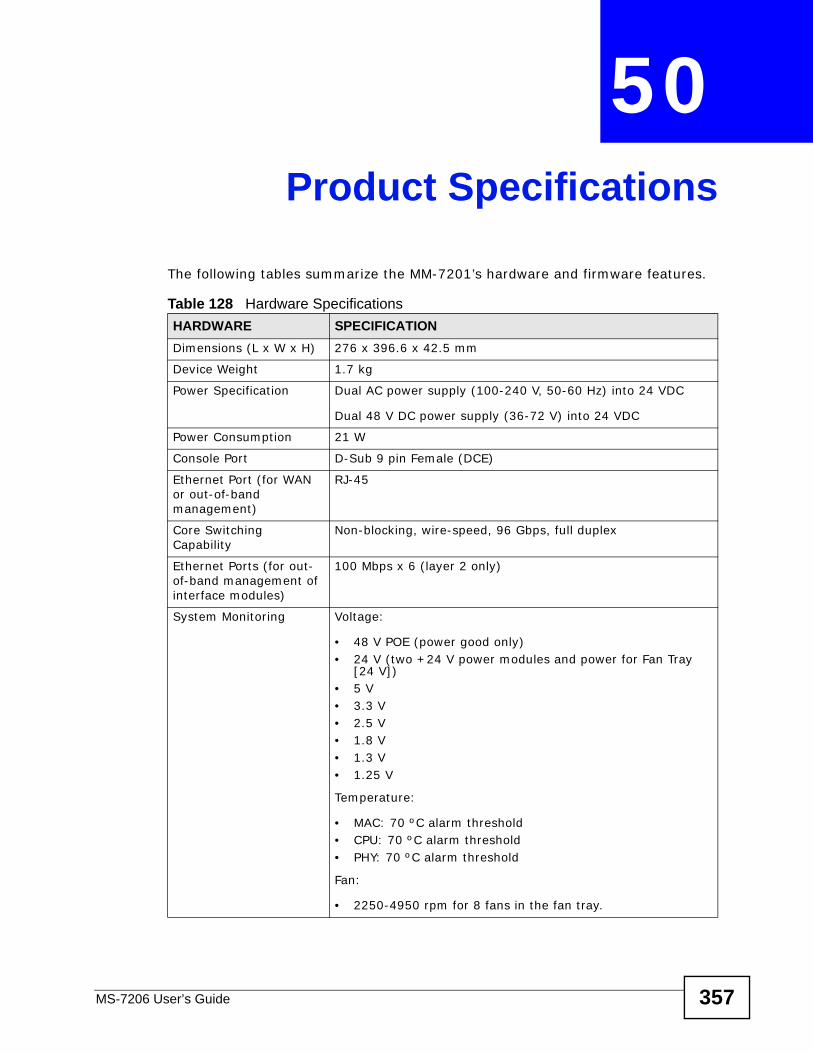
MS-7206 User’s Guide 357
CHAPTER 50 Product Specifications
The following tables summarize the MM-7201’s hardware and firmware features.
Table 128 Hardware SpecificationsHARDWARE SPECIFICATIONDimensions (L x W x H) 276 x 396.6 x 42.5 mm
Device Weight 1.7 kg
Power Specification Dual AC power supply (100-240 V, 50-60 Hz) into 24 VDC
Dual 48 V DC power supply (36-72 V) into 24 VDC
Power Consumption 21 W
Console Port D-Sub 9 pin Female (DCE)
Ethernet Port (for WAN or out-of-band management)
RJ-45
Core Switching Capability
Non-blocking, wire-speed, 96 Gbps, full duplex
Ethernet Ports (for out-of-band management of interface modules)
100 Mbps x 6 (layer 2 only)
System Monitoring Voltage:
• 48 V POE (power good only)• 24 V (two +24 V power modules and power for Fan Tray
[24 V])• 5 V• 3.3 V• 2.5 V• 1.8 V• 1.3 V• 1.25 V
Temperature:
• MAC: 70 ºC alarm threshold• CPU: 70 ºC alarm threshold • PHY: 70 ºC alarm threshold
Fan:
• 2250-4950 rpm for 8 fans in the fan tray.
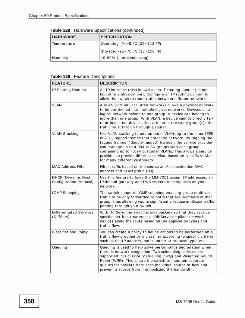
Chapter 50 Product Specifications
MS-7206 User’s Guide358
Temperature Operating: 0~45 ºC (32~113 ºF)
Storage: -25~70 ºC (13~158 ºF)
Humidity 10-90% (non-condensing)
Table 129 Feature DescriptionsFEATURE DESCRIPTIONIP Routing Domain An IP interface (also known as an IP routing domain) is not
bound to a physical port. Configure an IP routing domain to allow the switch to route traffic between different networks.
VLAN A VLAN (Virtual Local Area Network) allows a physical network to be partitioned into multiple logical networks. Devices on a logical network belong to one group. A device can belong to more than one group. With VLAN, a device cannot directly talk to or hear from devices that are not in the same group(s); the traffic must first go through a router.
VLAN Stacking Use VLAN stacking to add an outer VLAN tag to the inner IEEE 802.1Q tagged frames that enter the network. By tagging the tagged frames (“double-tagged” frames), the service provider can manage up to 4,094 VLAN groups with each group containing up to 4,094 customer VLANs. This allows a service provider to provide different service, based on specific VLANs, for many different customers.
MAC Address Filter Filter traffic based on the source and/or destination MAC address and VLAN group (ID).
DHCP (Dynamic Host Configuration Protocol)
Use this feature to have the MM-7201 assign IP addresses, an IP default gateway and DNS servers to computers on your network.
IGMP Snooping The switch supports IGMP snooping enabling group multicast traffic to be only forwarded to ports that are members of that group; thus allowing you to significantly reduce multicast traffic passing through your switch.
Differentiated Services (DiffServ)
With DiffServ, the switch marks packets so that they receive specific per-hop treatment at DiffServ-compliant network devices along the route based on the application types and traffic flow.
Classifier and Policy You can create a policy to define actions to be performed on a traffic flow grouped by a classifier according to specific criteria such as the IP address, port number or protocol type, etc.
Queuing Queuing is used to help solve performance degradation when there is network congestion. Two scheduling services are supported: Strict Priority Queuing (SPQ) and Weighted Round Robin (WRR). This allows the switch to maintain separate queues for packets from each individual source or flow and prevent a source from monopolizing the bandwidth.
Table 128 Hardware Specifications (continued)HARDWARE SPECIFICATION
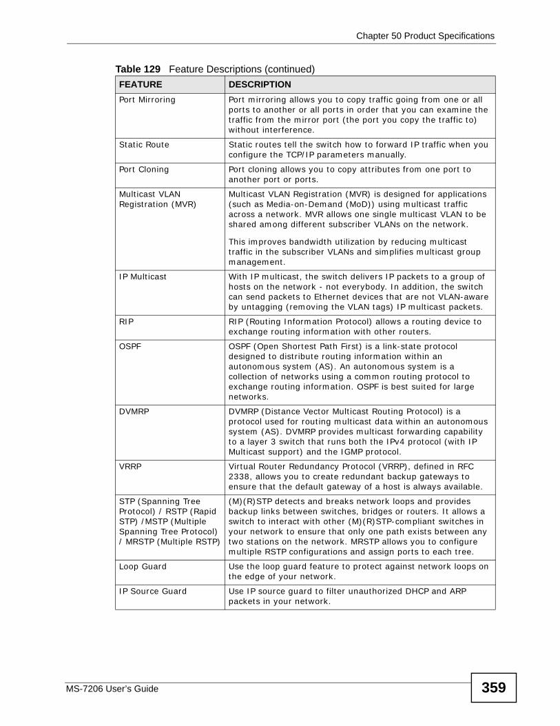
Chapter 50 Product Specifications
MS-7206 User’s Guide 359
Port Mirroring Port mirroring allows you to copy traffic going from one or all ports to another or all ports in order that you can examine the traffic from the mirror port (the port you copy the traffic to) without interference.
Static Route Static routes tell the switch how to forward IP traffic when you configure the TCP/IP parameters manually.
Port Cloning Port cloning allows you to copy attributes from one port to another port or ports.
Multicast VLAN Registration (MVR)
Multicast VLAN Registration (MVR) is designed for applications (such as Media-on-Demand (MoD)) using multicast traffic across a network. MVR allows one single multicast VLAN to be shared among different subscriber VLANs on the network.
This improves bandwidth utilization by reducing multicast traffic in the subscriber VLANs and simplifies multicast group management.
IP Multicast With IP multicast, the switch delivers IP packets to a group of hosts on the network - not everybody. In addition, the switch can send packets to Ethernet devices that are not VLAN-aware by untagging (removing the VLAN tags) IP multicast packets.
RIP RIP (Routing Information Protocol) allows a routing device to exchange routing information with other routers.
OSPF OSPF (Open Shortest Path First) is a link-state protocol designed to distribute routing information within an autonomous system (AS). An autonomous system is a collection of networks using a common routing protocol to exchange routing information. OSPF is best suited for large networks.
DVMRP DVMRP (Distance Vector Multicast Routing Protocol) is a protocol used for routing multicast data within an autonomous system (AS). DVMRP provides multicast forwarding capability to a layer 3 switch that runs both the IPv4 protocol (with IP Multicast support) and the IGMP protocol.
VRRP Virtual Router Redundancy Protocol (VRRP), defined in RFC 2338, allows you to create redundant backup gateways to ensure that the default gateway of a host is always available.
STP (Spanning Tree Protocol) / RSTP (Rapid STP) /MSTP (Multiple Spanning Tree Protocol) / MRSTP (Multiple RSTP)
(M)(R)STP detects and breaks network loops and provides backup links between switches, bridges or routers. It allows a switch to interact with other (M)(R)STP-compliant switches in your network to ensure that only one path exists between any two stations on the network. MRSTP allows you to configure multiple RSTP configurations and assign ports to each tree.
Loop Guard Use the loop guard feature to protect against network loops on the edge of your network.
IP Source Guard Use IP source guard to filter unauthorized DHCP and ARP packets in your network.
Table 129 Feature Descriptions (continued)FEATURE DESCRIPTION
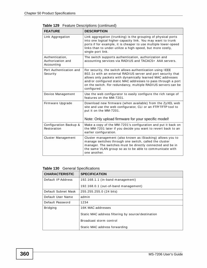
Chapter 50 Product Specifications
MS-7206 User’s Guide360
Link Aggregation Link aggregation (trunking) is the grouping of physical ports into one logical higher-capacity link. You may want to trunk ports if for example, it is cheaper to use multiple lower-speed links than to under-utilize a high-speed, but more costly, single-port link.
Authentication, Authorization and Accounting
The switch supports authentication, authorization and accounting services via RADIUS and TACACS+ AAA servers.
Port Authentication and Security
For security, the switch allows authentication using IEEE 802.1x with an external RADIUS server and port security that allows only packets with dynamically learned MAC addresses and/or configured static MAC addresses to pass through a port on the switch. For redundancy, multiple RADIUS servers can be configured.
Device Management Use the web configurator to easily configure the rich range of features on the MM-7201.
Firmware Upgrade Download new firmware (when available) from the ZyXEL web site and use the web configurator, CLI or an FTP/TFTP tool to put it on the MM-7201.
Note: Only upload firmware for your specific model!Configuration Backup & Restoration
Make a copy of the MM-7201’s configuration and put it back on the MM-7201 later if you decide you want to revert back to an earlier configuration.
Cluster Management Cluster management (also known as iStacking) allows you to manage switches through one switch, called the cluster manager. The switches must be directly connected and be in the same VLAN group so as to be able to communicate with one another.
Table 130 General SpecificationsCHARACTERISTIC SPECIFICATIONDefault IP Address 192.168.1.1 (in-band management)
192.168.0.1 (out-of-band management)
Default Subnet Mask 255.255.255.0 (24 bits)
Default User Name admin
Default Password 1234
Bridging 16K MAC addresses
Static MAC address filtering by source/destination
Broadcast storm control
Static MAC address forwarding
Table 129 Feature Descriptions (continued)FEATURE DESCRIPTION
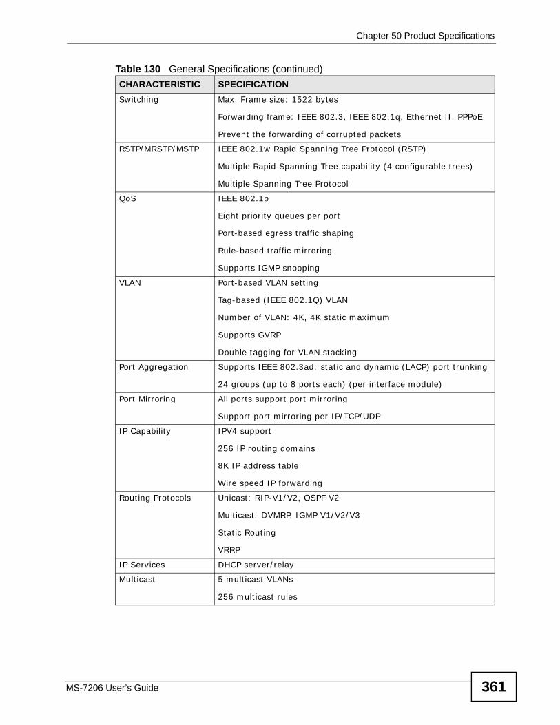
Chapter 50 Product Specifications
MS-7206 User’s Guide 361
Switching Max. Frame size: 1522 bytes
Forwarding frame: IEEE 802.3, IEEE 802.1q, Ethernet II, PPPoE
Prevent the forwarding of corrupted packets
RSTP/MRSTP/MSTP IEEE 802.1w Rapid Spanning Tree Protocol (RSTP)
Multiple Rapid Spanning Tree capability (4 configurable trees)
Multiple Spanning Tree Protocol
QoS IEEE 802.1p
Eight priority queues per port
Port-based egress traffic shaping
Rule-based traffic mirroring
Supports IGMP snooping
VLAN Port-based VLAN setting
Tag-based (IEEE 802.1Q) VLAN
Number of VLAN: 4K, 4K static maximum
Supports GVRP
Double tagging for VLAN stacking
Port Aggregation Supports IEEE 802.3ad; static and dynamic (LACP) port trunking
24 groups (up to 8 ports each) (per interface module)
Port Mirroring All ports support port mirroring
Support port mirroring per IP/TCP/UDP
IP Capability IPV4 support
256 IP routing domains
8K IP address table
Wire speed IP forwarding
Routing Protocols Unicast: RIP-V1/V2, OSPF V2
Multicast: DVMRP, IGMP V1/V2/V3
Static Routing
VRRP
IP Services DHCP server/relay
Multicast 5 multicast VLANs
256 multicast rules
Table 130 General Specifications (continued)CHARACTERISTIC SPECIFICATION
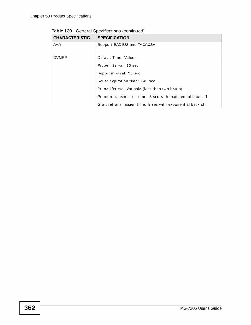
Chapter 50 Product Specifications
MS-7206 User’s Guide362
AAA Support RADIUS and TACACS+
DVMRP Default Timer Values
Probe interval: 10 sec
Report interval: 35 sec
Route expiration time: 140 sec
Prune lifetime: Variable (less than two hours)
Prune retransmission time: 3 sec with exponential back off
Graft retransmission time: 5 sec with exponential back off
Table 130 General Specifications (continued)CHARACTERISTIC SPECIFICATION
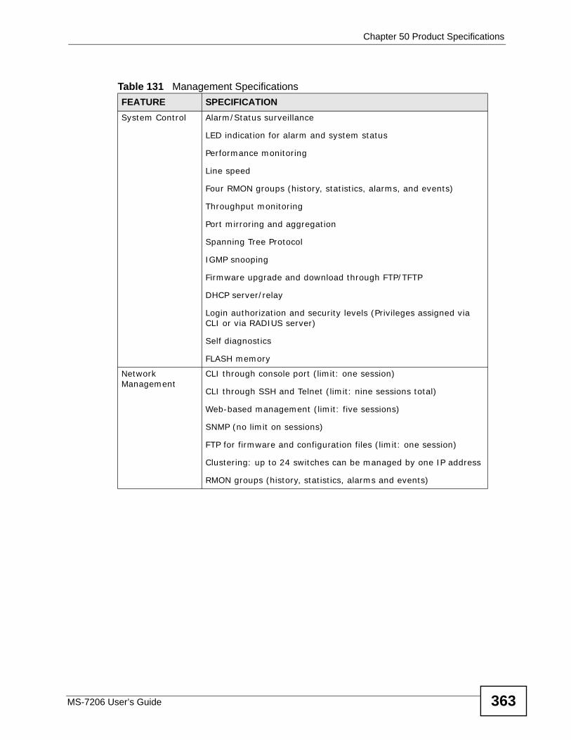
Chapter 50 Product Specifications
MS-7206 User’s Guide 363
Table 131 Management SpecificationsFEATURE SPECIFICATIONSystem Control Alarm/Status surveillance
LED indication for alarm and system status
Performance monitoring
Line speed
Four RMON groups (history, statistics, alarms, and events)
Throughput monitoring
Port mirroring and aggregation
Spanning Tree Protocol
IGMP snooping
Firmware upgrade and download through FTP/TFTP
DHCP server/relay
Login authorization and security levels (Privileges assigned via CLI or via RADIUS server)
Self diagnostics
FLASH memory
Network Management
CLI through console port (limit: one session)
CLI through SSH and Telnet (limit: nine sessions total)
Web-based management (limit: five sessions)
SNMP (no limit on sessions)
FTP for firmware and configuration files (limit: one session)
Clustering: up to 24 switches can be managed by one IP address
RMON groups (history, statistics, alarms and events)
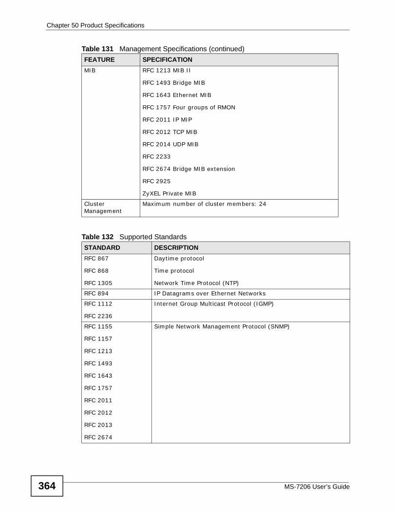
Chapter 50 Product Specifications
MS-7206 User’s Guide364
MIB RFC 1213 MIB II
RFC 1493 Bridge MIB
RFC 1643 Ethernet MIB
RFC 1757 Four groups of RMON
RFC 2011 IP MIP
RFC 2012 TCP MIB
RFC 2014 UDP MIB
RFC 2233
RFC 2674 Bridge MIB extension
RFC 2925
ZyXEL Private MIB
Cluster Management
Maximum number of cluster members: 24
Table 132 Supported StandardsSTANDARD DESCRIPTIONRFC 867
RFC 868
RFC 1305
Daytime protocol
Time protocol
Network Time Protocol (NTP)
RFC 894 IP Datagrams over Ethernet Networks
RFC 1112
RFC 2236
Internet Group Multicast Protocol (IGMP)
RFC 1155
RFC 1157
RFC 1213
RFC 1493
RFC 1643
RFC 1757
RFC 2011
RFC 2012
RFC 2013
RFC 2674
Simple Network Management Protocol (SNMP)
Table 131 Management Specifications (continued)FEATURE SPECIFICATION
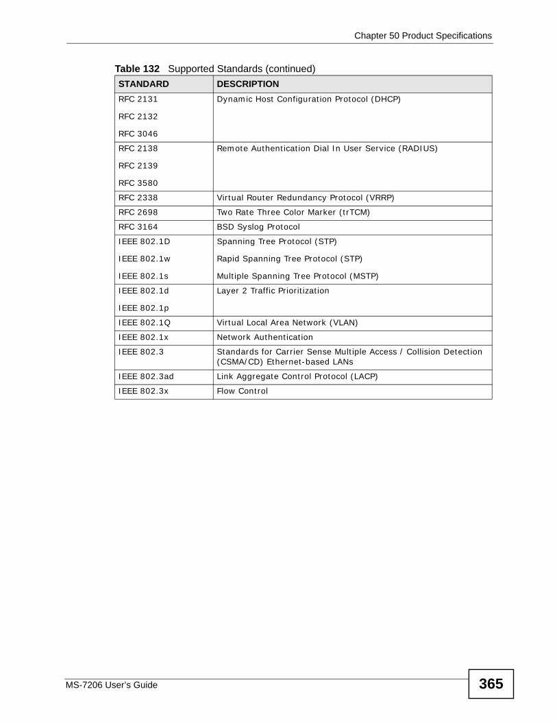
Chapter 50 Product Specifications
MS-7206 User’s Guide 365
RFC 2131
RFC 2132
RFC 3046
Dynamic Host Configuration Protocol (DHCP)
RFC 2138
RFC 2139
RFC 3580
Remote Authentication Dial In User Service (RADIUS)
RFC 2338 Virtual Router Redundancy Protocol (VRRP)
RFC 2698 Two Rate Three Color Marker (trTCM)
RFC 3164 BSD Syslog Protocol
IEEE 802.1D
IEEE 802.1w
IEEE 802.1s
Spanning Tree Protocol (STP)
Rapid Spanning Tree Protocol (STP)
Multiple Spanning Tree Protocol (MSTP)
IEEE 802.1d
IEEE 802.1p
Layer 2 Traffic Prioritization
IEEE 802.1Q Virtual Local Area Network (VLAN)
IEEE 802.1x Network Authentication
IEEE 802.3 Standards for Carrier Sense Multiple Access / Collision Detection (CSMA/CD) Ethernet-based LANs
IEEE 802.3ad Link Aggregate Control Protocol (LACP)
IEEE 802.3x Flow Control
Table 132 Supported Standards (continued)STANDARD DESCRIPTION
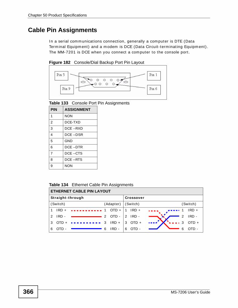
Chapter 50 Product Specifications
MS-7206 User’s Guide366
Cable Pin AssignmentsIn a serial communications connection, generally a computer is DTE (Data Terminal Equipment) and a modem is DCE (Data Circuit-terminating Equipment). The MM-7201 is DCE when you connect a computer to the console port.
Figure 182 Console/Dial Backup Port Pin Layout
Table 133 Console Port Pin AssignmentsPIN ASSIGNMENT1 NON
2 DCE-TXD
3 DCE –RXD
4 DCE –DSR
5 GND
6 DCE –DTR
7 DCE –CTS
8 DCE –RTS
9 NON
Table 134 Ethernet Cable Pin AssignmentsETHERNET CABLE PIN LAYOUTStraight-through Crossover
(Switch) (Adapter) (Switch) (Switch)
1 IRD + 1 OTD + 1 IRD + 1 IRD +
2 IRD - 2 OTD - 2 IRD - 2 IRD -
3 OTD + 3 IRD + 3 OTD + 3 OTD +
6 OTD - 6 IRD - 6 OTD - 6 OTD -

367
PART VIIIAppendices and
IndexIP Addresses and Subnetting (369)
Legal Information (381)
Index (385)

368
MS-7206 User’s Guide 369
APPENDIX A IP Addresses and Subnetting
This appendix introduces IP addresses and subnet masks.
IP addresses identify individual devices on a network. Every networking device (including computers, servers, routers, printers, etc.) needs an IP address to communicate across the network. These networking devices are also known as hosts.
Subnet masks determine the maximum number of possible hosts on a network. You can also use subnet masks to divide one network into multiple sub-networks.
Introduction to IP AddressesOne part of the IP address is the network number, and the other part is the host ID. In the same way that houses on a street share a common street name, the hosts on a network share a common network number. Similarly, as each house has its own house number, each host on the network has its own unique identifying number - the host ID. Routers use the network number to send packets to the correct network, while the host ID determines to which host on the network the packets are delivered.
StructureAn IP address is made up of four parts, written in dotted decimal notation (for example, 192.168.1.1). Each of these four parts is known as an octet. An octet is an eight-digit binary number (for example 11000000, which is 192 in decimal notation).
Therefore, each octet has a possible range of 00000000 to 11111111 in binary, or 0 to 255 in decimal.
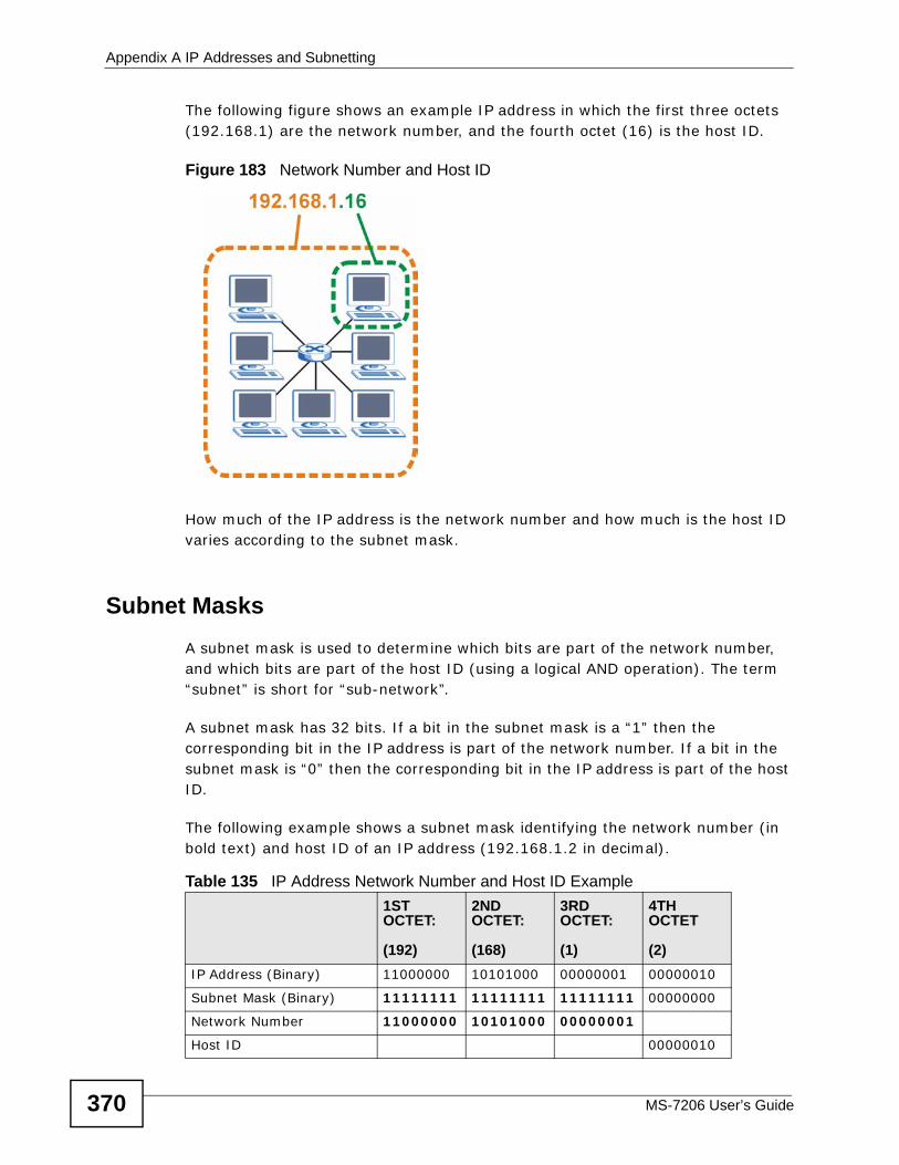
Appendix A IP Addresses and Subnetting
MS-7206 User’s Guide370
The following figure shows an example IP address in which the first three octets (192.168.1) are the network number, and the fourth octet (16) is the host ID.
Figure 183 Network Number and Host ID
How much of the IP address is the network number and how much is the host ID varies according to the subnet mask.
Subnet MasksA subnet mask is used to determine which bits are part of the network number, and which bits are part of the host ID (using a logical AND operation). The term “subnet” is short for “sub-network”.
A subnet mask has 32 bits. If a bit in the subnet mask is a “1” then the corresponding bit in the IP address is part of the network number. If a bit in the subnet mask is “0” then the corresponding bit in the IP address is part of the host ID.
The following example shows a subnet mask identifying the network number (in bold text) and host ID of an IP address (192.168.1.2 in decimal).
Table 135 IP Address Network Number and Host ID Example1ST OCTET:
(192)
2ND OCTET:
(168)
3RD OCTET:
(1)
4TH OCTET
(2)IP Address (Binary) 11000000 10101000 00000001 00000010
Subnet Mask (Binary) 11111111 11111111 11111111 00000000
Network Number 11000000 10101000 00000001
Host ID 00000010
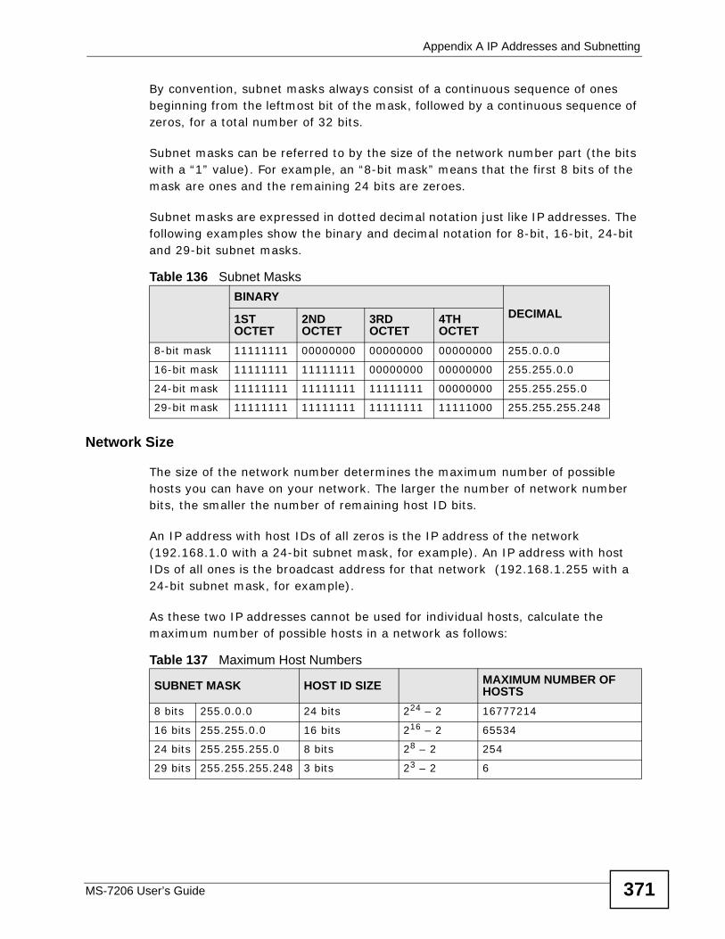
Appendix A IP Addresses and Subnetting
MS-7206 User’s Guide 371
By convention, subnet masks always consist of a continuous sequence of ones beginning from the leftmost bit of the mask, followed by a continuous sequence of zeros, for a total number of 32 bits.
Subnet masks can be referred to by the size of the network number part (the bits with a “1” value). For example, an “8-bit mask” means that the first 8 bits of the mask are ones and the remaining 24 bits are zeroes.
Subnet masks are expressed in dotted decimal notation just like IP addresses. The following examples show the binary and decimal notation for 8-bit, 16-bit, 24-bit and 29-bit subnet masks.
Network Size
The size of the network number determines the maximum number of possible hosts you can have on your network. The larger the number of network number bits, the smaller the number of remaining host ID bits.
An IP address with host IDs of all zeros is the IP address of the network (192.168.1.0 with a 24-bit subnet mask, for example). An IP address with host IDs of all ones is the broadcast address for that network (192.168.1.255 with a 24-bit subnet mask, for example).
As these two IP addresses cannot be used for individual hosts, calculate the maximum number of possible hosts in a network as follows:
Table 136 Subnet MasksBINARY
DECIMAL1ST OCTET
2ND OCTET
3RD OCTET
4TH OCTET
8-bit mask 11111111 00000000 00000000 00000000 255.0.0.0
16-bit mask 11111111 11111111 00000000 00000000 255.255.0.0
24-bit mask 11111111 11111111 11111111 00000000 255.255.255.0
29-bit mask 11111111 11111111 11111111 11111000 255.255.255.248
Table 137 Maximum Host Numbers
SUBNET MASK HOST ID SIZE MAXIMUM NUMBER OF HOSTS
8 bits 255.0.0.0 24 bits 224 – 2 16777214
16 bits 255.255.0.0 16 bits 216 – 2 65534
24 bits 255.255.255.0 8 bits 28 – 2 254
29 bits 255.255.255.248 3 bits 23 – 2 6
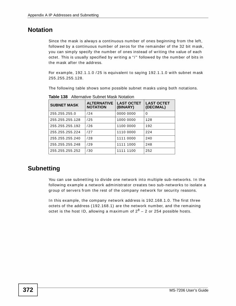
Appendix A IP Addresses and Subnetting
MS-7206 User’s Guide372
NotationSince the mask is always a continuous number of ones beginning from the left, followed by a continuous number of zeros for the remainder of the 32 bit mask, you can simply specify the number of ones instead of writing the value of each octet. This is usually specified by writing a “/” followed by the number of bits in the mask after the address.
For example, 192.1.1.0 /25 is equivalent to saying 192.1.1.0 with subnet mask 255.255.255.128.
The following table shows some possible subnet masks using both notations.
SubnettingYou can use subnetting to divide one network into multiple sub-networks. In the following example a network administrator creates two sub-networks to isolate a group of servers from the rest of the company network for security reasons.
In this example, the company network address is 192.168.1.0. The first three octets of the address (192.168.1) are the network number, and the remaining octet is the host ID, allowing a maximum of 28 – 2 or 254 possible hosts.
Table 138 Alternative Subnet Mask Notation
SUBNET MASK ALTERNATIVE NOTATION
LAST OCTET (BINARY)
LAST OCTET (DECIMAL)
255.255.255.0 /24 0000 0000 0
255.255.255.128 /25 1000 0000 128
255.255.255.192 /26 1100 0000 192
255.255.255.224 /27 1110 0000 224
255.255.255.240 /28 1111 0000 240
255.255.255.248 /29 1111 1000 248
255.255.255.252 /30 1111 1100 252
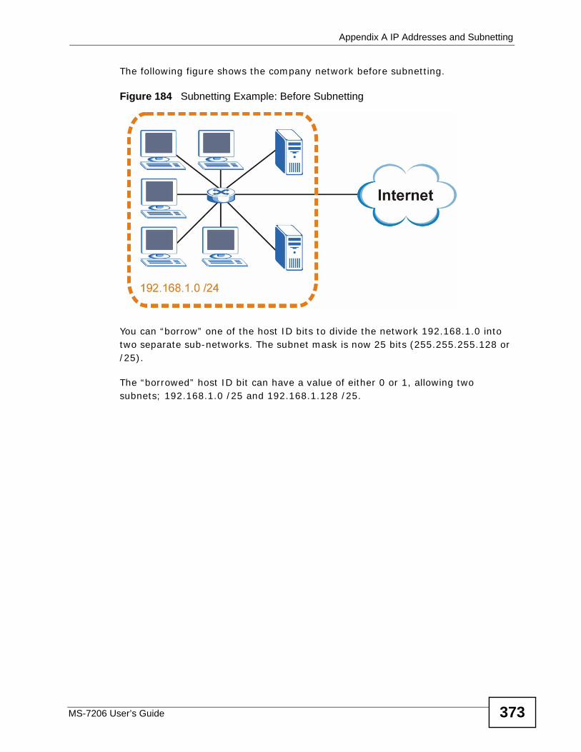
Appendix A IP Addresses and Subnetting
MS-7206 User’s Guide 373
The following figure shows the company network before subnetting.
Figure 184 Subnetting Example: Before Subnetting
You can “borrow” one of the host ID bits to divide the network 192.168.1.0 into two separate sub-networks. The subnet mask is now 25 bits (255.255.255.128 or /25).
The “borrowed” host ID bit can have a value of either 0 or 1, allowing two subnets; 192.168.1.0 /25 and 192.168.1.128 /25.
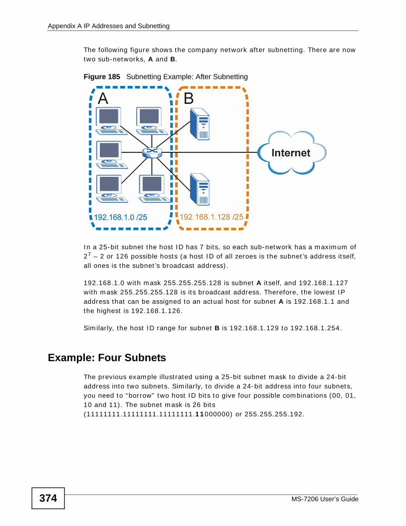
Appendix A IP Addresses and Subnetting
MS-7206 User’s Guide374
The following figure shows the company network after subnetting. There are now two sub-networks, A and B.
Figure 185 Subnetting Example: After Subnetting
In a 25-bit subnet the host ID has 7 bits, so each sub-network has a maximum of 27 – 2 or 126 possible hosts (a host ID of all zeroes is the subnet’s address itself, all ones is the subnet’s broadcast address).
192.168.1.0 with mask 255.255.255.128 is subnet A itself, and 192.168.1.127 with mask 255.255.255.128 is its broadcast address. Therefore, the lowest IP address that can be assigned to an actual host for subnet A is 192.168.1.1 and the highest is 192.168.1.126.
Similarly, the host ID range for subnet B is 192.168.1.129 to 192.168.1.254.
Example: Four Subnets The previous example illustrated using a 25-bit subnet mask to divide a 24-bit address into two subnets. Similarly, to divide a 24-bit address into four subnets, you need to “borrow” two host ID bits to give four possible combinations (00, 01, 10 and 11). The subnet mask is 26 bits (11111111.11111111.11111111.11000000) or 255.255.255.192.
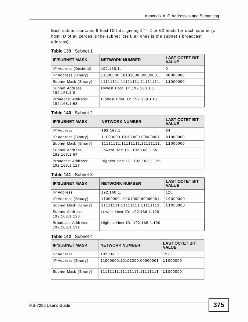
Appendix A IP Addresses and Subnetting
MS-7206 User’s Guide 375
Each subnet contains 6 host ID bits, giving 26 - 2 or 62 hosts for each subnet (a host ID of all zeroes is the subnet itself, all ones is the subnet’s broadcast address).
Table 139 Subnet 1
IP/SUBNET MASK NETWORK NUMBER LAST OCTET BIT VALUE
IP Address (Decimal) 192.168.1. 0
IP Address (Binary) 11000000.10101000.00000001. 00000000
Subnet Mask (Binary) 11111111.11111111.11111111. 11000000
Subnet Address: 192.168.1.0
Lowest Host ID: 192.168.1.1
Broadcast Address: 192.168.1.63
Highest Host ID: 192.168.1.62
Table 140 Subnet 2
IP/SUBNET MASK NETWORK NUMBER LAST OCTET BIT VALUE
IP Address 192.168.1. 64
IP Address (Binary) 11000000.10101000.00000001. 01000000
Subnet Mask (Binary) 11111111.11111111.11111111. 11000000
Subnet Address: 192.168.1.64
Lowest Host ID: 192.168.1.65
Broadcast Address: 192.168.1.127
Highest Host ID: 192.168.1.126
Table 141 Subnet 3
IP/SUBNET MASK NETWORK NUMBER LAST OCTET BIT VALUE
IP Address 192.168.1. 128
IP Address (Binary) 11000000.10101000.00000001. 10000000
Subnet Mask (Binary) 11111111.11111111.11111111. 11000000
Subnet Address: 192.168.1.128
Lowest Host ID: 192.168.1.129
Broadcast Address: 192.168.1.191
Highest Host ID: 192.168.1.190
Table 142 Subnet 4
IP/SUBNET MASK NETWORK NUMBER LAST OCTET BIT VALUE
IP Address 192.168.1. 192
IP Address (Binary) 11000000.10101000.00000001.
11000000
Subnet Mask (Binary) 11111111.11111111.11111111.
11000000
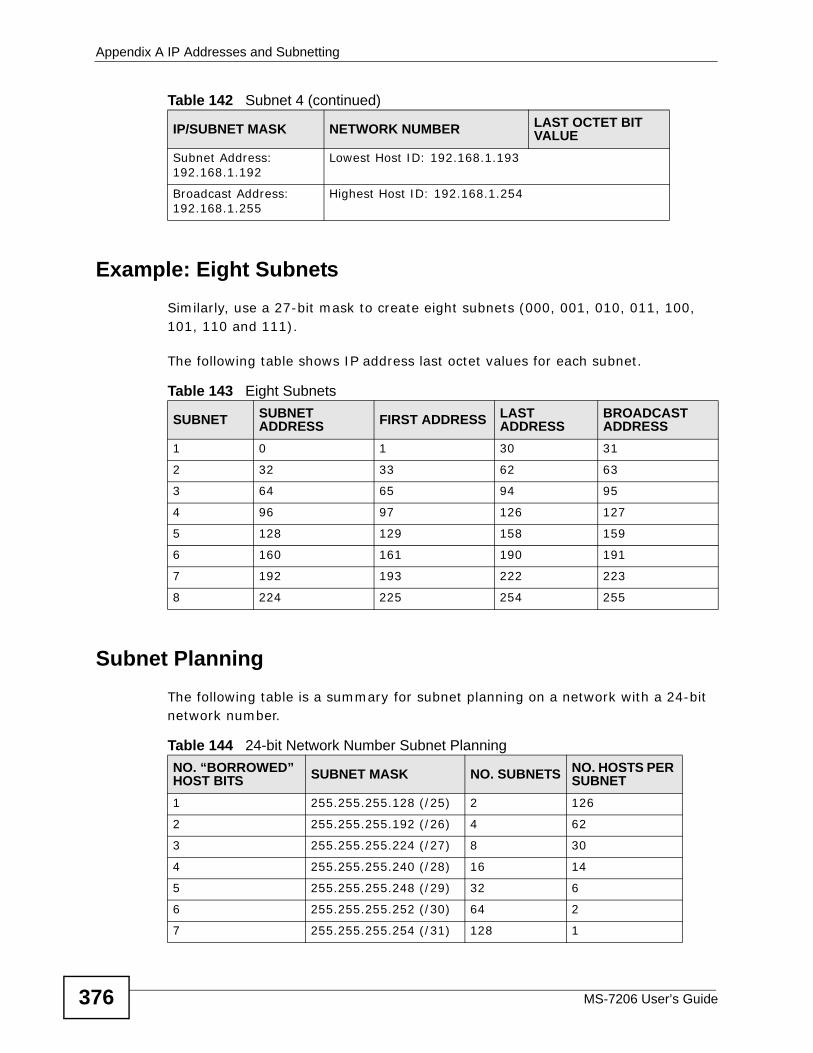
Appendix A IP Addresses and Subnetting
MS-7206 User’s Guide376
Example: Eight SubnetsSimilarly, use a 27-bit mask to create eight subnets (000, 001, 010, 011, 100, 101, 110 and 111).
The following table shows IP address last octet values for each subnet.
Subnet PlanningThe following table is a summary for subnet planning on a network with a 24-bit network number.
Subnet Address: 192.168.1.192
Lowest Host ID: 192.168.1.193
Broadcast Address: 192.168.1.255
Highest Host ID: 192.168.1.254
Table 142 Subnet 4 (continued)
IP/SUBNET MASK NETWORK NUMBER LAST OCTET BIT VALUE
Table 143 Eight Subnets
SUBNET SUBNET ADDRESS FIRST ADDRESS LAST
ADDRESSBROADCAST ADDRESS
1 0 1 30 31
2 32 33 62 63
3 64 65 94 95
4 96 97 126 127
5 128 129 158 159
6 160 161 190 191
7 192 193 222 223
8 224 225 254 255
Table 144 24-bit Network Number Subnet PlanningNO. “BORROWED” HOST BITS SUBNET MASK NO. SUBNETS NO. HOSTS PER
SUBNET1 255.255.255.128 (/25) 2 126
2 255.255.255.192 (/26) 4 62
3 255.255.255.224 (/27) 8 30
4 255.255.255.240 (/28) 16 14
5 255.255.255.248 (/29) 32 6
6 255.255.255.252 (/30) 64 2
7 255.255.255.254 (/31) 128 1
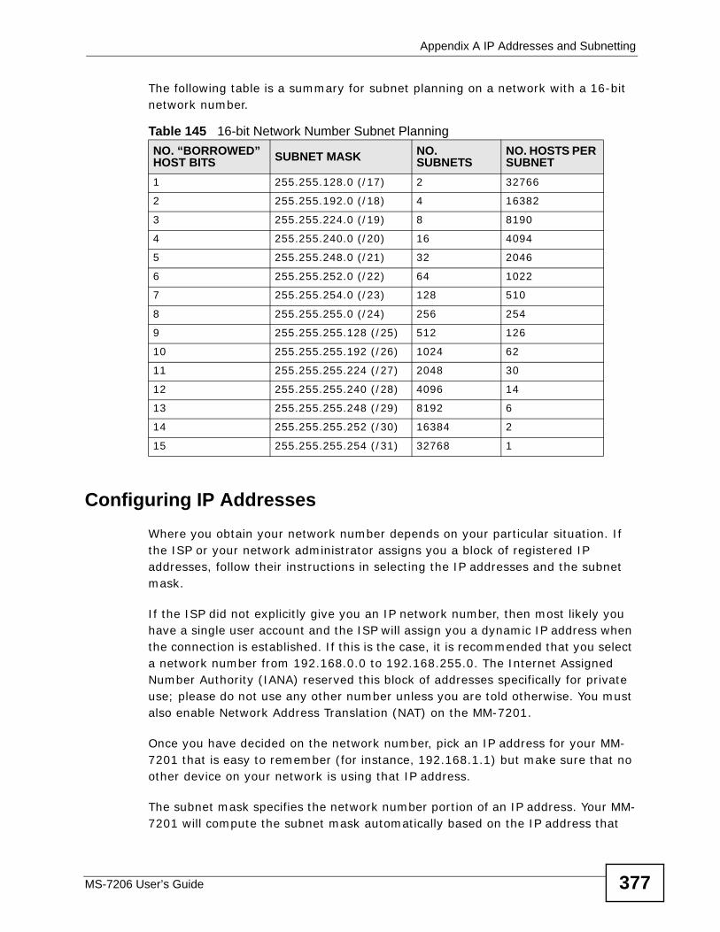
Appendix A IP Addresses and Subnetting
MS-7206 User’s Guide 377
The following table is a summary for subnet planning on a network with a 16-bit network number.
Configuring IP AddressesWhere you obtain your network number depends on your particular situation. If the ISP or your network administrator assigns you a block of registered IP addresses, follow their instructions in selecting the IP addresses and the subnet mask.
If the ISP did not explicitly give you an IP network number, then most likely you have a single user account and the ISP will assign you a dynamic IP address when the connection is established. If this is the case, it is recommended that you select a network number from 192.168.0.0 to 192.168.255.0. The Internet Assigned Number Authority (IANA) reserved this block of addresses specifically for private use; please do not use any other number unless you are told otherwise. You must also enable Network Address Translation (NAT) on the MM-7201.
Once you have decided on the network number, pick an IP address for your MM-7201 that is easy to remember (for instance, 192.168.1.1) but make sure that no other device on your network is using that IP address.
The subnet mask specifies the network number portion of an IP address. Your MM-7201 will compute the subnet mask automatically based on the IP address that
Table 145 16-bit Network Number Subnet PlanningNO. “BORROWED” HOST BITS SUBNET MASK NO.
SUBNETSNO. HOSTS PER SUBNET
1 255.255.128.0 (/17) 2 32766
2 255.255.192.0 (/18) 4 16382
3 255.255.224.0 (/19) 8 8190
4 255.255.240.0 (/20) 16 4094
5 255.255.248.0 (/21) 32 2046
6 255.255.252.0 (/22) 64 1022
7 255.255.254.0 (/23) 128 510
8 255.255.255.0 (/24) 256 254
9 255.255.255.128 (/25) 512 126
10 255.255.255.192 (/26) 1024 62
11 255.255.255.224 (/27) 2048 30
12 255.255.255.240 (/28) 4096 14
13 255.255.255.248 (/29) 8192 6
14 255.255.255.252 (/30) 16384 2
15 255.255.255.254 (/31) 32768 1
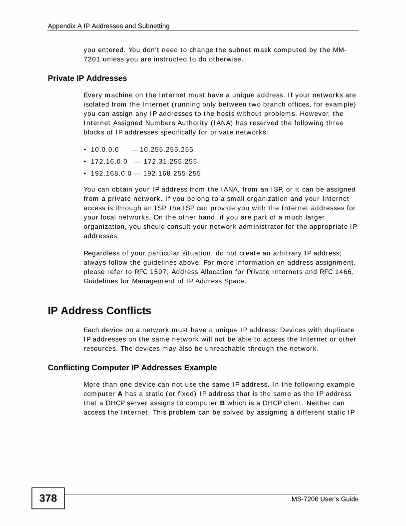
Appendix A IP Addresses and Subnetting
MS-7206 User’s Guide378
you entered. You don't need to change the subnet mask computed by the MM-7201 unless you are instructed to do otherwise.
Private IP Addresses
Every machine on the Internet must have a unique address. If your networks are isolated from the Internet (running only between two branch offices, for example) you can assign any IP addresses to the hosts without problems. However, the Internet Assigned Numbers Authority (IANA) has reserved the following three blocks of IP addresses specifically for private networks:
• 10.0.0.0 — 10.255.255.255
• 172.16.0.0 — 172.31.255.255
• 192.168.0.0 — 192.168.255.255
You can obtain your IP address from the IANA, from an ISP, or it can be assigned from a private network. If you belong to a small organization and your Internet access is through an ISP, the ISP can provide you with the Internet addresses for your local networks. On the other hand, if you are part of a much larger organization, you should consult your network administrator for the appropriate IP addresses.
Regardless of your particular situation, do not create an arbitrary IP address; always follow the guidelines above. For more information on address assignment, please refer to RFC 1597, Address Allocation for Private Internets and RFC 1466, Guidelines for Management of IP Address Space.
IP Address ConflictsEach device on a network must have a unique IP address. Devices with duplicate IP addresses on the same network will not be able to access the Internet or other resources. The devices may also be unreachable through the network.
Conflicting Computer IP Addresses Example
More than one device can not use the same IP address. In the following example computer A has a static (or fixed) IP address that is the same as the IP address that a DHCP server assigns to computer B which is a DHCP client. Neither can access the Internet. This problem can be solved by assigning a different static IP
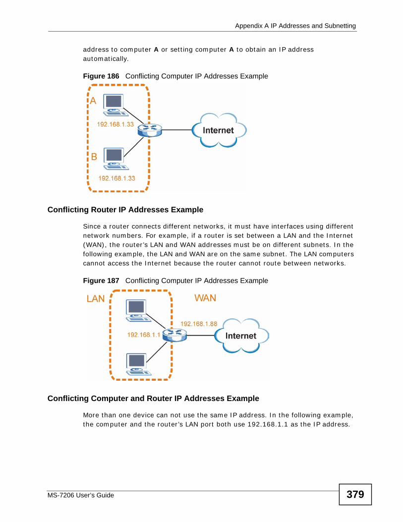
Appendix A IP Addresses and Subnetting
MS-7206 User’s Guide 379
address to computer A or setting computer A to obtain an IP address automatically.
Figure 186 Conflicting Computer IP Addresses Example
Conflicting Router IP Addresses Example
Since a router connects different networks, it must have interfaces using different network numbers. For example, if a router is set between a LAN and the Internet (WAN), the router’s LAN and WAN addresses must be on different subnets. In the following example, the LAN and WAN are on the same subnet. The LAN computers cannot access the Internet because the router cannot route between networks.
Figure 187 Conflicting Computer IP Addresses Example
Conflicting Computer and Router IP Addresses Example
More than one device can not use the same IP address. In the following example, the computer and the router’s LAN port both use 192.168.1.1 as the IP address.
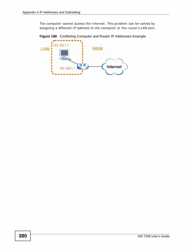
Appendix A IP Addresses and Subnetting
MS-7206 User’s Guide380
The computer cannot access the Internet. This problem can be solved by assigning a different IP address to the computer or the router’s LAN port.
Figure 188 Conflicting Computer and Router IP Addresses Example
MS-7206 User’s Guide 381
APPENDIX B Legal Information
CopyrightCopyright © 2009 by ZyXEL Communications Corporation.
The contents of this publication may not be reproduced in any part or as a whole, transcribed, stored in a retrieval system, translated into any language, or transmitted in any form or by any means, electronic, mechanical, magnetic, optical, chemical, photocopying, manual, or otherwise, without the prior written permission of ZyXEL Communications Corporation.
Published by ZyXEL Communications Corporation. All rights reserved.
Disclaimer
ZyXEL does not assume any liability arising out of the application or use of any products, or software described herein. Neither does it convey any license under its patent rights nor the patent rights of others. ZyXEL further reserves the right to make changes in any products described herein without notice. This publication is subject to change without notice.
Trademarks
ZyNOS (ZyXEL Network Operating System) is a registered trademark of ZyXEL Communications, Inc. Other trademarks mentioned in this publication are used for identification purposes only and may be properties of their respective owners.
Certifications
Federal Communications Commission (FCC) Interference Statement
This device complies with Part 15 of FCC rules. Operation is subject to the following two conditions:
• This device may not cause harmful interference.
Appendix B Legal Information
MS-7206 User’s Guide382
• This device must accept any interference received, including interference that may cause undesired operations.
FCC Warning
This device has been tested and found to comply with the limits for a Class A digital switch, pursuant to Part 15 of the FCC Rules. These limits are designed to provide reasonable protection against harmful interference in a commercial environment. This device generates, uses, and can radiate radio frequency energy and, if not installed and used in accordance with the instruction manual, may cause harmful interference to radio communications. Operation of this device in a residential area is likely to cause harmful interference in which case the user will be required to correct the interference at his own expense.
CE Mark Warning:
This is a class A product. In a domestic environment this product may cause radio interference in which case the user may be required to take adequate measures.
Taiwanese BSMI (Bureau of Standards, Metrology and Inspection) A Warning:
Notices
Changes or modifications not expressly approved by the party responsible for compliance could void the user's authority to operate the equipment.
This Class A digital apparatus complies with Canadian ICES-003.
Cet appareil numérique de la classe A est conforme à la norme NMB-003 du Canada.
Viewing Certifications
1 Go to http://www.zyxel.com.
2 Select your product on the ZyXEL home page to go to that product's page.
3 Select the certification you wish to view from this page.
Appendix B Legal Information
MS-7206 User’s Guide 383
ZyXEL Limited WarrantyZyXEL warrants to the original end user (purchaser) that this product is free from any defects in materials or workmanship for a period of up to two years from the date of purchase. During the warranty period, and upon proof of purchase, should the product have indications of failure due to faulty workmanship and/or materials, ZyXEL will, at its discretion, repair or replace the defective products or components without charge for either parts or labor, and to whatever extent it shall deem necessary to restore the product or components to proper operating condition. Any replacement will consist of a new or re-manufactured functionally equivalent product of equal or higher value, and will be solely at the discretion of ZyXEL. This warranty shall not apply if the product has been modified, misused, tampered with, damaged by an act of God, or subjected to abnormal working conditions.
Note
Repair or replacement, as provided under this warranty, is the exclusive remedy of the purchaser. This warranty is in lieu of all other warranties, express or implied, including any implied warranty of merchantability or fitness for a particular use or purpose. ZyXEL shall in no event be held liable for indirect or consequential damages of any kind to the purchaser.
To obtain the services of this warranty, contact your vendor. You may also refer to the warranty policy for the region in which you bought the device at http://www.zyxel.com/web/support_warranty_info.php.
Registration
Register your product online to receive e-mail notices of firmware upgrades and information at www.zyxel.com.

Appendix B Legal Information
MS-7206 User’s Guide384
Index
MS-7206 User’s Guide 385
Index
Numerics
802.1P priority 80
A
AAA 195ABR 246access control
login account 311remote management 320service port 319SNMP 301
accounting 195setup 201
address learning, MAC 95, 98Address Resolution Protocol, see ARP
administrator password 312age 121aggregator ID 140aging time 70alternative subnet mask notation 372Area Border Router, see ABR
area IDand OSPF 251
ARP 343how it works 343viewing 344
ARP inspection 207, 210and MAC filter 210configuring 211syslog messages 211trusted ports 211
AS 245AS Boundary Router 246authentication 195, 251
OSPF 251setup 201
Authentication, Authorization and Accounting, see AAA
authorization 195privilege levels 202setup 201
automatic VLAN registration 86Autonomous System
and OSPF 245Autonomous System, see AS
B
back up, configuration file 296Backbone Router, see BR
backbone, routing 245Backup Designated Router, see BDR
basic settings 61BDR 247
and OSPF 247binding 207binding table 207
building 207BPDU 106BR 246Bridge Protocol Data Unit, see BPDU
C
Canonical Format Indicator, see CFI
certifications 381notices 382viewing 382
CFI 86changing the password 44CIST 110Class of Service, see CoS
classifier 155, 158and QoS 155
Index
MS-7206 User’s Guide386
example 159overview 155setup 155, 158
cloning a port See port cloning 348cluster management 327, 328
and switch passwords 333cluster manager 327, 333cluster member 327, 333cluster member firmware upgrade 330network example 328setup 332specification 327status 328switch models 327VID 333web configurator 329
cluster manager 327cluster member 327Common and Internal Spanning Tree, See CIST
110configuration 242
configurationfile names 297
configuration file 45backup 296restore 45, 296saving 294
configuration, saving 44copying port settings, See port cloning 348copyright 381CoS 263current date 66current time 66
D
Database Description, see DD
daylight saving time 66DD 246default gateway 277DHCP 271
client IP pool 277configuration options 271modes 271relay agent 271
server 271status 277VLAN setting 276
DHCP relay option 82 209DHCP snooping 207, 208
configuring 209DHCP relay option 82 209trusted ports 208untrusted ports 208
DHCP snooping database 208diagnostics 321
Ethernet port test 322ping 322system log 322
Differentiated Service, see DiffServ
Differentiated Services, see DS
DiffServ 263activate 266and TRTCM 268DS field 263DSCP 263DSCP-to-IEEE802.1p mapping 269network example 264PHB 263
DiffServ Code Point, see DSCP
disclaimer 381Distance Vector Multicast Routing Protocol, see
DVMRP
double-tagged frames 173DR 247
and OSPF Designated Router, see DR
DS 263DSCP 263
DSCP-to-IEEE802.1p mapping 269service level 263what it does 263
DVMRP 259Autonomous System 259default timer setting 262error message 261graft 260how it works 259implementation 259probe 260prune 260report 260setup 260terminology 260
Index
MS-7206 User’s Guide 387
threshold 261Dynamic Host Configuration Protocol, see DHCP
dynamic link aggregation 135
E
Ethernet broadcast address 343Ethernet port test 322external authentication server 196
F
Fair Queuing 170fan speed 63FCC interference statement 381file transfer using FTP
command example 298filename convention 297filtering 103
rules 103filtering database, MAC table 335firmware 56, 62
upgrade 294, 330flow control 80
back pressure 80IEEE 802.3x 80
forwardingdelay 121
FQ (Fair Queuing) 170frames
tagged 94untagged 94
front panel 31FTP 297
file transfer procedure 299restrictions over WAN 300
G
GARP 86GARP terminology 87
GARP timer 70, 87general setup 65Generic Attribute Registration Protocol, see
GARP
getting help 47GMT (Greenwich Mean Time) 66GVRP 87, 93, 94
and port assignment 94GVRP (GARP VLAN Registration Protocol) 87
H
hardware overview 31hello time 121hops 121HTTPS 314
certificates 314implementation 314public keys, private keys 314
HTTPS example 315
I
IANA 378IEEE 802.1p, priority 70IEEE 802.1x 143
activate 146, 199port authentication 143reauthentication 147
IGMP 257setup 257version 179, 258
IGMP (Internet Group Multicast Protocol) 179IGMP filtering 179
profile 185profiles 182
IGMP leave timeoutfast 183normal 183
IGMP snooping 180and VLANs 180MVR 186setup 183
Index
MS-7206 User’s Guide388
interface 248and OSPF 252
interface, and OSPF 246Internal Router, see IR
Internet Assigned Numbers AuthoritySee IANA 378
IPinterface 73, 284routing domain 73setup 74
IP source guard 207ARP inspection 207, 210DHCP snooping 207, 208static bindings 207
IP table 339how it works 339
IR 246
L
LACP 135system priority 141timeout 142
LEDs 27limit MAC address learning 151Link Aggregate Control Protocol, see LACP
link aggregation 135dynamic 135ID information 136setup 140status 137traffic distribution algorithm 138traffic distribution type 140
Link State Advertisement, see LSA
link state database 246, 248lockout 45log 322login 39
password 44login account
Administrator 311non-administrator 311
login accounts 311configuring via web configurator 311multiple 311
number of 311login password 312loop guard 233
examples 234port shut down 235setup 235vs. STP 233
LSA 246
M
MAC (Media Access Control) 62MAC address 62, 343
maximum number per port 151, 152MAC address learning 69, 95, 98, 101, 151
specify limit 151MAC authentication 143
aging time 148example 144
MAC filterand ARP inspection 210
MAC freeze 150MAC table 335
how it works 335maintenance 293
configuration backup 296current configuration 293firmware 294main screen 293restoring configuration 296
Management Information Base (MIB) 302managing the device
good habits 26using FTP. See FTP. 26using HTTP/HTTPS. See web configurator. 26using SNMP. See SNMP. 26using Telnet. See command interface. 26using the command interface. See command
interface. 26man-in-the-middle attacks 210max
age 121hops 121
metric 251MIB
and SNMP 302
Index
MS-7206 User’s Guide 389
supported MIBs 303MIB (Management Information Base) 302mirroring ports 133monitor port 133mrouter 260MST ID 109MST Instance, See MSTI 109MST region 109MSTI 109MSTP 108
bridge ID 124configuration 120configuration digest 124forwarding delay 121Hello Time 124hello time 121Max Age 124max age 121max hops 121path cost 122port priority 122revision level 121status 123
MTU (Multi-Tenant Unit) 85multicast 179
802.1 priority 182and IGMP 179IP addresses 179overview 179setup 181, 182
multicast delivery tree 260multicast group 185multicast router 260multicast VLAN 190Multiple Spanning Tree Protocol 107Multiple Spanning Tree Protocol, See MSTP 108Multiple STP 107, 108MVR 186
configuration 188group configuration 190network example 186
MVR (Multicast VLAN Registration) 186
N
NAT 377network management system (NMS) 301NTP (RFC 1305) 66
O
Open Shortest Path First, see OSPF
OSPF 245advantages 245area 245Area 0 245area ID 251authentication 251autonomous system 245backbone 245configuration steps 247general settings 250how it works 246interface 246, 248, 252link state database 246, 248network example 246priority 247redistribute route 251route cost 252router elections 247router ID 250router types 246status 248stub area 245, 251virtual link 247vs RIP 245
P
password 44administrator 312
Per-Hop Behavior, see PHB
PHB 263ping, test connection 322policy 164
and classifier 164and DiffServ 161configuration 164
Index
MS-7206 User’s Guide390
example 166overview 161rules 161
port authentication 143and RADIUS 196, 197and VSA 205IEEE 802.1x 143, 146IEEE802.1x 199MAC authentication 143
port cloning 347, 348advanced settings 347, 348basic settings 347, 348
port details 57port mirroring 133
direction 134egress 134ingress 134
port redundancy 135port security 149
limit MAC address learning 151MAC address learning 149overview 149setup 150, 235
port setup 79port status 56port VLAN trunking 87ports
diagnostics 322mirroring 133speed/duplex 80standby 135
powervoltage 64
power status 64priority frame 86priority level 70priority, and OSPF 247priority, queue assignment 70product registration 383protocol based VLAN 97
and IEEE 802.1Q tagging 97example 100hexadecimal notation for protocols 99isolate traffic 97priority 99
PVID 86, 94
Q
QoSand classifier 155
Queue priority 172Queue weight 172queue weight 170queuing 169
FQ 170SPQ 169WFQ 170WRR 169
Queuing algorithm 172Queuing method 172queuing method 169
R
RADIUS 195, 196advantages 196and port authentication 196Network example 196server 196settings 197setup 197
Rapid Spanning Tree Protocol (RSTP). See STP 105
redistribute route 251registration
product 383related documentation 3remote management 320
service 320trusted computers 320
resetting 45, 294to factory default settings 294
restoring configuration 45, 296Reverse Path Forwarding, see RPF
Reverse Path Multicasting, see RPM
RFC 3164 323RFC 3580 205RIP
configuration 243version 244vs OSPF 245
Index
MS-7206 User’s Guide 391
Round Robin Scheduling 169router ID 250routing domain 73, 284routing protocols 251routing table 345RPF 260RPM 259RSTP 105
See also STP 105
S
safety warnings 7save configuration 44, 294Secure Shell See SSH 313service access control 319
service port 319Simple Network Management Protocol, See
SNMP 301slot setup 77slot status 55SNMP 301
agent 302and MIB 302and security 303authentication 309communities 308management model 302manager 302MIB 303network components 302object variables 302protocol operations 302security 309setup 310traps 303version 3 303versions supported 301
SNMP traps 303setup 310supported 303, 304, 305, 307
Spanning Tree Protocol (STP) 105SPQ (Strict Priority Queuing) 169SSH
encryption methods 314
how it works 313implementation 314
SSH (Secure Shell) 313SSL (Secure Socket Layer) 314standby ports 135static bindings 207static MAC address 101static MAC forwarding 95, 98, 101static routes 241, 242Static VLAN 91static VLAN
control 92tagging 92
status 40, 55link aggregation 137MSTP 123OSPF 248port details 57port status 56power 64STP 114, 118VLAN 89VRRP 283
STP 105bridge ID 115, 119bridge priority 113, 117configuration 112, 116designated bridge 106forwarding delay 113, 117Hello BPDU 106Hello Time 113, 115, 117, 119how it works 106Max Age 113, 115, 117, 119path cost 106, 114, 117port priority 114, 117port state 107root port 106status 114, 118terminology 105vs. loop guard 233
stub area 245, 251stub area, See also OSPF 251subnet 369subnet based VLAN 96
and DHCP VLAN 96priority 96setup 95

Index
MS-7206 User’s Guide392
subnet based VLANs 94subnet mask 370subnetting 372switch lockout 45switch reset 45switch setup 69syntax conventions 5syslog 211, 323
protocol 323server setup 325settings 324setup 324severity levels 323
system information 61, 63system log 322
T
TACACS+ 195, 196setup 199
tagged VLAN 85temperature indicator 64Terminal Access Controller Access-Control
System Plus, see TACACS+
timecurrent 66time zone 66
Time (RFC 868) 66time server 66time service protocol 66
format 66Time To Live, see TTL
ToS 263trademarks 381traps
destination 309SNMP 303
TRTCMand bandwidth control 268and DiffServ 268color-aware mode 265color-blind mode 265setup 267
trunk group 135
trunking 135trusted ports
ARP inspection 211DHCP snooping 208
TTL 261tunnel protocol attribute 205Two Rate Three Color Marker (TRTCM) 264Type of Service, see ToS
U
untrusted portsARP inspection 211DHCP snooping 208
user profiles 196
V
Vendor Specific Attribute, See VSA 204VID 75, 85, 86, 89, 90, 175
number of possible VIDs 86priority frame 86
virtual links 255virtual links, and OSPF 247Virtual Router
status 283Virtual Router (VR) 281Virtual Router Redundancy Protocol (VRRP) 281VLAN 85
acceptable frame type 94automatic registration 86ID 85IGMP snooping 180ingress filtering 94introduction 85number of VLANs 89port number 90port settings 93static VLAN 91status 89, 90subnet based 94tagged 85trunking 87, 94
VLAN (Virtual Local Area Network) 85
Index
MS-7206 User’s Guide 393
VLAN Identifier, see VID
VLAN number 75VLAN stacking 173, 175
configuration 177example 173frame format 175port roles 174, 178priority 175
VLAN, protocol based, see protocol based VLAN
VRID (Virtual Router ID) 283VRRP 281
advertisement interval 282authentication 284backup router 281configuration example 286Hello message 282how it works 281master router 281network example 281, 286parameters 282preempt mode 283, 285priority 282, 285status 283uplink gateway 285uplink status 283Virtual Router 281Virtual Router ID 285VRID 283
VSA 204, 205and port authentication 205
W
warranty 383note 383
web configurator 39getting help 47home 40login 39logout 46navigation panel 41
weight, queuing 170Weighted Fair Queuing 170Weighted Round Robin Scheduling (WRR) 170WFQ (Weighted Fair Queuing) 170WRR (Weighted Round Robin Scheduling) 169
Z
ZyNOS (ZyXEL Network Operating System) 298

Index
MS-7206 User’s Guide394