Embed Size (px)
Citation preview

Technical Data
SMC™-3 SpecificationsBulletin Number 150
Additional Resources
These documents contain additional information concerning related products from Rockwell Automation.
You can view or download publications at http://www.rockwellautomation.com/literature/. To order paper copies of technical documentation, contact your local Allen-Bradley distributor or Rockwell Automation sales representative.
Topic Page
Product Overview 2
Standards Compliance and Certifications 2
Features 3
Catalog Number Explanation 4
Wiring Diagrams 6
General Specifications 8
Approximate Dimensions 13
Resource Description
Industrial Automation Wiring and Grounding Guidelines, publication 1770-4.1 Provides general guidelines for installing a Rockwell Automation industrial system.
Product Certifications website, http://www.ab.com Provides declarations of conformity, certificates, and other certification details.

2
Product Overview Bulletin 150 SMC™-3 Specifications
Features
SMC™-3
200…600V1…480 A
Soft Start S
Kickstart S
Current Limit S
Soft Stop S
Integrated Bypass Contactor S
Integrated Motor Overload Protection S
Inside Delta Connection S
Standards Compliance:CE Marked per Low Voltage Directive73/23/EEC, 93/68/EECCSA Certified (File No. LR 1234)UL Listed (File No. E96956)
S
S = Standard Feature
Standards ComplianceUL 508CSA C22.2 No.14EN/IEC 60947-1EN/IEC 60947-4-2
CertificationscULus Listed (Open Type) (File No. E96956, Guides NMFT, NMFT7)CSA Certified (File No. LR 1234)CE Marked (Open Type) per EMC and Low Voltage DirectiveCCC Certified
Modes of Operation� Soft Start � Selectable Kickstart� Current Limit Start � Soft Stop
Note: For detailed information about the different modes of operation, see page 3

3
Bulletin 150 SMC™-3 Specifications Features
Description of FeaturesElectronic Motor Overload ProtectionThe SMC-3 controller incorporates, as standard, electronic motoroverload protection. This motor overload protection is accomplishedelectronically with the use of current transformers on each of thethree phases. The controller’s overload protection is programmable,providing the user with flexibility. The overload trip class selectionconsists of either OFF, 10, 15, or 20. The trip current is easilyselected by adjusting the rotary potentiometer to the motor full-loadcurrent rating. Trip reset is selectable to either automatic or manualmode.Note: Trip rating is 120% of dial setting.
Over-temperatureThe SMC-3 monitors the SCR temperature by means of internalthermistors. When the power poles maximum rated temperature isreached, the microcomputer switches off the SMC, a TEMP fault isindicated via LED, and the 97/98 fault contact closes.
Phase Reversal ProtectionWhen enabled via a DIP switch, 3-phase input power will be verifiedbefore starting. If input power phasing is detected to be incorrect,the start will be aborted and a fault indicated.
Phase Loss/Open LoadThe unit will not attempt a start if there is a single-phase conditionon the line. This protects from motor burnout during single-phasestarting.
Phase ImbalanceThe unit monitors for imbalance between phase currents. To preventmotor damage, the unit will trip if the difference between theminimum phase current and the maximum phase current exceeds65% for 3 s, and a fault will be indicated.
Shorted SCRPrior to every start and during starting, the unit will check all SCRsfor shorts and unit load connections to the motor. If there is ashorted SCR in the SMC-3 and/or open load, the start will beaborted and a shorted SCR or open load fault will be indicated. Thisprevents damage from phase imbalance.
Push to TestThe unit with control wiring can be tested for fault conditions byusing the Push to Test function. Hold down the Reset button for 7 sto activate the fault Aux (97, 98) and shut down the SMC-3. To clear,either push the Reset button or cycle control power to the device.
LED Description (Number of Flashes)1. Overload2. Overtemperature3. Phase Reversal4. Phase Loss/Open Load5. Phase Imbalance6. Shorted SCR7. Test

4 Rockwell Automation Publication 150-TD007A-EN-P
Catalog Number Explanation Bulletin 150 SMC™-3 Specifications
Cat. No. ExplanationOpen and Non-Combination
150 – C 30 F B D – 8La b c d e f g
aBulletin Number
Code Description
150 Solid-State Controller
bController Type
Code Description
C SMC-3
cAmpere Ratings
Code Description
3 3 A
9 9 A
16 16 A
19 19 A
25 25 A
30 30 A
37 37 A
43 43 A
60 60 A
85 85 A
108 108 A
135 135 A
201 201 A
251 251 A
317 317 A
361 361 A
480 480 A
dEnclosure Type
Code Description
N Open
F NEMA 4/12 (IP65)
eInput Line Voltage
Open Type
Code Description
B 200…460V AC, 3-Phase, 50/60 Hz
C 200…600V AC, 3-Phase, 50/60 Hz
Non-Combination Enclosed Only
H 200…208V AC, 3-Phase, 50/60 Hz
A 230V AC, 3-Phase, 50/60 Hz
B 400…460V AC, 3-Phase, 50/60 Hz
C 500…575V AC, 3-Phase, 50/60 Hz
fControl Voltage
Code Description
D 100…240V AC
R 24V AC/DC (Open Type only)
gOptions (see page 42 for a full listing)
Code Description
8L Line-Mounted Protective Module
8M Load-Mounted Protective Module
8B Line- and Load-Mounted ProtectiveModules
Load-side MOVs are not available with Pumpand Braking options, or when used with inside-
the-delta connections.

5
Bulletin 150 SMC™-3 Specifications Catalog Number Explanation
Combination
152H – C 30 F BD 43 – 8La b c d e f g
aBulletin Number
Code Description
152H‡ Solid-State Controller with FusibleDisconnect
153H‡ Solid-State Controller with Circuit Breaker
bController Type
Code Description
C SMC-3
cAmpere Ratings
Code Description
3 3 A
9 9 A
16 16 A
19 19 A
25‡ 25 A
30 30 A
37 37 A
43‡ 43 A
60 60 A
85‡ 85 A
108‡ 108 A
135‡ 135 A
201‡ 201 A
251 251 A
317‡ 317 A
361‡ 361 A
480‡ 480 A
dEnclosure Type
Code Description
F NEMA Type 4/12 (IP65)
X‡ NEMA Type 3R (IP44)
eInput Line Voltage
Open Type
Code Description
HD 200…208V AC, 3-Phase, 50/60 Hz
AD 230V AC, 3-Phase, 50/60 Hz
BD‡ 400…460V AC, 3-Phase, 50/60 Hz
CD 500…575V AC, 3-Phase, 50/60 Hz
fHorsepower
Cat.No.
HpRating
Cat.No.
HpRating
Cat.No.
HpRating
Cat.No.
HpRating
Cat.No.
HpRating
33 0.5 39 5 46‡ 40 52‡ 150 60 450
34 0.75 40 7.5 47‡ 50 54 200 61 500
35 1 41‡ 10 48‡ 60 56‡ 250 62 600
36 1.5 42‡ 15 49‡ 75 57‡ 300 63 700
37 2 43‡ 20 50‡ 100 58‡ 350 65 800
38 3 44‡ 25 51‡ 125 59‡ 400 67 1000
— — 45‡ 30 — — — — — —
gOptions (see page 42 for a full listing)
Code Description
8L Line-Mounted Protective Module
8M Load-Mounted Protective Module
8B Line- and Load-Mounted ProtectiveModules
Load-side MOVs are not available with Pumpand Braking options, or when used with inside-
the-delta connections.
‡ Pump Panel only available for highlightedconfiguration. Start push button, external reset,HOA, and transformer are included as standard.

6 Rockwell Automation Publication 150-TD007A-EN-P
Wiring Diagrams Bulletin 150 SMC™-3 Specifications
Two-Wire ConfigurationIEC
SMC-3 Control Terminals
E-Stop
H4H2
H1H3
X1 X2
Trans.
Ground
A2A1 IN1 IN2
OVLD/Fault AUX #1
97 98 13 14
-TC
-SB
Two-WireDevice
-E1
-E1(PowerConnections)
NEMA
Three-Wire ConfigurationIEC
SMC-3 Control Terminals
E-Stop
H4H2
H1H3
X1 X2
Trans.
Ground
A2A1 IN1 IN2
OVLD/Fault AUX #1
97 98 13 14
-TC
-SB1
-E1
-E1(PowerConnections)
Stop Option-SB2
Start-SB3
NEMA

7Rockwell Automation Publication 150-TD007A-EN-P
Bulletin 150 SMC™-3 Specifications Wiring Diagrams
SMC-3 Control Terminals
H4H2
H1H3
X1 X2Trans.
Ground
A2A1 IN1 IN2
OVLD/Fault AUX #1
97 98 13 14
-E1
-TC
-SB1E-Stop
-KM
-E1(PowerConnections)
-SB3Start
-SB2Stop Option
-KM
NEMA
Motor
L3/5
T1/2L1/1
T2/4
T3/6
L2/3
SMC-3(Power connections)
SMC-3 Control Terminals
E-StopH4H2
H1H3
X1 X2Trans. Ground
A2A1 IN1 IN2
OVLD/Fault AUX #1
97 98 13 14
IC
ICStop Option Start
Reversing ConfigurationNote: Minimum Off time equals 1.0 s.
IEC
Isolation Contactor ConfigurationIEC
SMC-3 Control Terminals
H4H2
H1H3
X1 X2
Trans.
Ground
A2A1 IN1 IN2
OVLD/Fault AUX #1
97 98 13 14
-E1(PowerConnections)
-TC
-KM2-KM1
-SBE-Stop
-KM2-KM1
-KM2 -KM1 -KM2 -KM1
-SA
FOR REVOFF
NEMA
Motor
L3/5
T1/2L1/1
T2/4
T3/6
L2/3
SMC-3(Power connections)
SMC-3 Control Terminals
E-Stop H4H2
H1H3
X1 X2
Trans. Ground
A2A1 IN1 IN2
OVLD/Fault AUX #1
97 98 13 14
F
FR
R
F
R
FOR REVOFF
F
R

8 Rockwell Automation Publication 150-TD007A-EN-P
Specifications Bulletin 150 SMC™-3 Specifications
Standard FeaturesSelectable Start Times 2, 5, 10, 15, 20, 25, or 30 sSelectable Initial Torque 0%, 25%, 35%, and 65% of locked rotor torqueSelectable Current Limit 150%, 250%, 350%, and 450% of full load currentSelectable Kick Start — 450% FLA 0, 0.5, 1.0, or 1.5 sSelectable Soft Stop Off, 100%, 200%, or 300% of the start time setting when wired
Electrical RatingsUL/CSA/NEMA IEC
Power Circuit
Rated Operation Voltage 200…480V AC200…600V AC
200…480V~ — 400V~500V~ — 500V~
Rated Insulation Voltage 600V AC 500V~Dielectric Withstand 2200V AC 2500V~
Repetitive Peak 200…480V AC: 1400V200…600V AC: 1600V
200…480V~: 1400V500V~: 1600V
Operating Frequency 50/60 Hz 50/60 Hz
UtilizationCategory
1…37 A ⎯ AC-53b: 3.5-15:358543…60 A ⎯ AC-53b: 4.5-30:1770
85 A ⎯ AC-53b: 4.5-30:3570108 A ⎯ AC-53b: 4.5-30:1770135 A ⎯ AC-53b: 3.5-30: 1770
201…251 A ⎯ AC-53b: 3.5-30: 1770317…480 A ⎯ AC-53b: 3.5-30: 1770
Number of Poles Equipment designed for 3-phase onlyRated Impulse Voltage 6 kVDV/DT Protection 1000V/μsOvervoltage Category III
Short CircuitProtection
SCPD PerformanceType 1♣Δ
Non-Time Delay Thermal Magnetic Circuit Breaker High Capacity Time DelayClass CC/J/L
SCPD List§ Max. StandardAvailable Fault
Max. StandardFuse [A]‡
Max. StandardAvailable Fault
Max. CircuitBreaker [A]
Max. StandardAvailable Fault Max. Fuse [A]
Line DeviceOperationalCurrent Rating[A]
3 5 kA 12 5 kA 15 70 kA 69 5 kA 30 5 kA 30 70 kA 1516 5 kA 60 5 kA 60 70 kA 3019 5 kA 70 5 kA 70 70 kA 4025 5 kA 100 5 kA 100 70 kA 5030 10 kA 110 10 kA 110 70 kA 6037 10 kA 125 10 kA 125 70 kA 6043 10 kA 150 10 kA 150 70 kA 9060 10 kA 225 10 kA 225 70 kA 12585 10 kA 300 10 kA 300 70 kA 175108 10 kA 400 10 kA 300 70 kA 200135 10 kA 500 10 kA 400 70 kA 250201 18 kA 600 18 kA 600 70 kA 350251 18 kA 700 18 kA 700 70 kA 400317 30 kA 800 30 kA 800 69 kA 500361 30 kA 1000 30 kA 1000 69 kA 600480 42 kA 1200 42 kA 1200 69 kA 800
Delta DeviceOperationalCurrent Rating[A]
5.1 5 kA 15 5 kA 15 70 kA 1016 5 kA 60 5 kA 60 70 kA 30
27.6 5 kA 70 5 kA 70 70 kA 6032.8 5 kA 125 5 kA 125 70 kA 7043 5 kA 150 5 kA 150 70 kA 9052 10 kA 200 10 kA 200 70 kA 10064 10 kA 250 10 kA 250 70 kA 10074 10 kA 250 10 kA 250 70 kA 150104 10 kA 400 10 kA 300 70 kA 225147 10 kA 400 10 kA 400 70 kA 300187 10 kA 600 10 kA 500 70 kA 400234 10 kA 700 10 kA 700 70 kA 400348 18 kA 1000 18 kA 1000 70 kA 600435 18 kA 1200 18 kA 1200 69 kA 800549 30 kA 1600 30 kA 1600 69 kA 1000625 30 kA 1600 30 kA 1600 69 kA 1200831 42 kA 1600 30 kA 1600 69 kA 1600831 42 kA 1600 42 kA 1200 69 kA 1600
‡ Non-time delay fuses (K5).§ Consult local codes for proper sizing of short-circuit protection.♣ Type 1 performance/protection indicates that, under a short-circuit condition, the fused or circuit breaker-protected starter shall cause no danger to persons or
installation but may not be suitable for further service without repair or replacement.

9Rockwell Automation Publication 150-TD007A-EN-P
Bulletin 150 SMC™-3 Specifications Specifications
Electrical RatingsUL/CSA/NEMA IEC
Control Circuit
Rated Operational Voltage (+10%, –15%) 100…240V AC, 24V AC/DC 100…240V~, 24V AC/DCRated Insulation Voltage 250V 250V~Rated Impulse Voltage 2.5 kV 4 kVDielectric Withstand 1500V AC 2000V~Overvoltage Category II III�Operating Frequency 50/60 Hz 50/60 HzInput onstate voltage minimum, during start (IN1, IN2) 85V AC, 19.2V DC / 19.2V ACInput onstate current (IN1, IN2) 9.8 mA @120V AC/19.6 mA @ 240V AC, 7.3 mA @ 24V AC/DCInput offstate voltage maximum (IN1, IN2) 40V AC, 17V DC / 12V ACInput offstate current @ input offstate voltage (IN1, IN2) <10 mA, <12 mA
Control Power with Fan, during start
3…37 A 215 mA @ 120V AC / 180 mA @ 240V AC, 800 mA @ 24V DC / 660 mA @24V AC
43…85 A 200 mA @ 120V AC / 100 mA @ 240V AC, 700 mA @ 24V AC/DCFan Power Control Power
108…135 A 20VA200 mA @ 120V AC / 120 mA @ 240V AC, 600 mA @ 24V
AC/DC201…251 A 40VA317…480 A 60VA
Control Power without Fan, during start 3…37 A 205 mA @ 120V AC / 145 mA @ 240V AC, 705 mA @ 24V DC / 580 mA @24V AC
Steady State Heat Dissipation and Overload Current Range
Controller Rating [A] Steady State Heat Dissipation [W] Overload Current Range [A]3 11 1…39 12 3…9
16 14 5.3…1619 15 6.3…1925 17 9.2…27.730 19 10…3037 24 12.3…3743 34 14.3…4360 50 20…6085 82 28.3…85
108 62 27…108135 75 34…135201 129 67…201251 147 84…251317 174 106…317361 194 120…361480 239 160…480
Auxiliary ContactsUL/CSA/NEMA IEC
Rated Operational Voltage 250V AC/30V DC 250V~/30V DCRated Insulation Voltage 250V 250V~Rated Impulse Voltage 2.5 kV 4 kVDielectric Withstand 1500V AC 2000V~Overvoltage Category II III�Operating Frequency 50/60 Hz 50/60 HzUtilization Category D300/D300 AC-15/DC
TB-97, -98 (OVLD/Fault)
Type of Control Circuit Electromagnetic relayNumber of Contacts 1Type of Contacts Normally Open (N.O.)Type of Current AC/DCRated Operational Current (max.) 0.6 A @ 120V~ and 0.3 A @ 240V~Conventional Thermal Current Ith 1 AMake/Break VA 432/72
TB-13, -14 Aux 1(Normal/Up-to-Speed)
Type of Control Circuit Electromagnetic relayNumber of Contacts 1Type of Contacts Normally Open (N.O.)Type of Current AC/DCRated Operational Current (max.) 0.6 A @ 120V~ and 0.3 A @ 240V~Conventional Thermal Current Ith 1 AMake/Break VA 432/72
�Overvoltage category II, when either control or auxiliary circuit is wired to a SELV or PELV circuit.

10 Rockwell Automation Publication 150-TD007A-EN-P
Specifications Bulletin 150 SMC™-3 Specifications
Electrical RatingsSide-Mount Auxiliary Contacts
UL/CSA/NEMA IECRated Operational Voltage 250V AC/30V DC 250V AC/30V DCRated Insulation Voltage 250V 250V ACRated Impulse Voltage 2.5 kV 4 kVDielectric Withstand 1500V AC 2000V ACOvervoltage Category II III�Operating Frequency 50/60 Hz 50/60 Hz
TB-23, -24(Normal/Up-to-Speed)TB-33, -34(Normal/Up-to-Speed)
Utilization Category C300/R150 AC-15/DC-13Type of Control Circuit Electromagnetic relayNumber of Contacts 1Type of Contacts Normally Open (N.O.)Type of Current AC/DCRated Operational Current (max.) 1.5 A @ 120V AC, 0.75A @ 240V AC, 1.17 A @ 24V DCConventional Thermal Current Ith 2.5 AMake/Break VA 1800/180V AC, 28V DC (resistive)
TB-11, -12 (Normal/Up-to-Speed)
Type of Control Circuit B300/R300 AC-15/DC-13Type of Control Circuit Electromagnetic relayNumber of Contacts 1Type of Contacts Normally Closed (N.C.)Type of Current AC/DCRated Operational Current (max.) 3 A @ 120V AC, 1.5A @ 240V AC, 1.17 A @ 24V DCConventional Thermal Current Ith 5 AMake/Break VA 3600/360VA, 28VA (DC resistive)
�Overvoltage category II, when either control or auxiliary circuit is wired to a SELV or PELV circuit.
Environmental
Operating Temperature Range -5…+50 °C (23…122 °F) (open)-5…+40 °C (23…104 °F) (enclosed)
Storage and Transportation Temperature Range -25…+85 °C (-13…+185 °F)Altitude 2000 m (6560 ft)Humidity 5…95% (non-condensing)Pollution Degree 2Type of Protection IP2X
Mechanical Ratings
Resistance to VibrationOperational 1.0 G Peak, 0.15 mm (0.006 in.) displacementNon-Operational 2.5 G Peak, 0.38 mm (0.015 in.) displacement
Resistance to ShockOperational 15 GNon-Operational 30 G
Line Power Terminals Cable SizeTightening Torque
3…37 A 2.5…25 mm2 (14…4 AWG)2.3…2.8 N•m (20…25 in•lbs)
43…85 A 2.5…95 mm2 (14…3/0 AWG)11.3…12.4 N•m (100…110 in•lbs)
108…135 A 23 N•m (200 in•lbs)201…251 A Two M10 x 1.5 diameter holes per power pole317…480 A Two M12 x 1.75 diameter holes per power pole
Load Power Terminals Cable SizeTightening Torque
3…37 A 2.5…16 mm2 (14…6 AWG)2.3…2.5 N•m (20…22.5 in•lbs)
43…85 A 2.5…50 mm2 (14…1 AWG)11.3…12.4 N•m (100…110 in•lbs)
108…135 A 23 N•m (200 in•lbs)201…251 A Two M10 x 1.5 diameter holes per power pole317…480 A Two M12 x 1.75 diameter holes per power pole
Control Terminals Cable SizeTightening Torque All 0.2…2.5 mm2 (24…14 AWG)
0.5…0.9 N•m (4.4…8.0 in•lbs)Other
UL/CSA/NEMA IEC
EMC Emission LevelsConducted Radio Frequency Emissions ⎯ Class ARadiated Emissions ⎯ Class A
EMC Immunity Levels
Electrostatic Discharge 4 kV Contact and 8 kVAir Discharge 8 kV Air Discharge
Radio Frequency Electromagnetic Field ⎯ Per EN/IEC 60947-4-2Fast Transient ⎯ Per EN/IEC 60947-4-2Surge Transient ⎯ Per EN/IEC 60947-4-2

11
Bulletin 150 SMC™-3 Specifications Specificationst (
sec)
Current
Cold Trip
Hot Trip
Trip Class 15
t (se
c)
Current
Cold Trip
Hot Trip
Trip Class 20
t (se
c)
Current
Cold Trip
Hot Trip
SMC-3 Overload Trip CurvesTrip Class 10
12 Rockwell Automation Publication 150-TD007A-EN-P
Specifications Bulletin 150 SMC™-3 Specifications
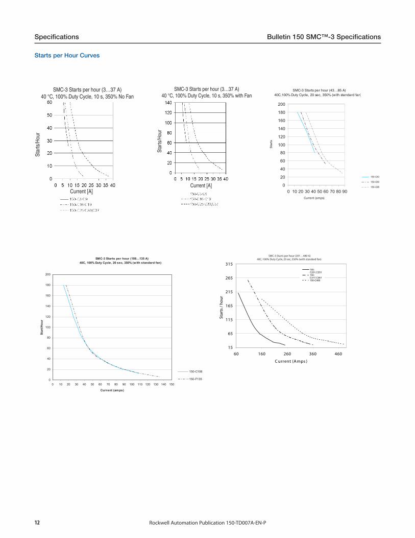
SMC-3 Starts per hour (108…135 A)40C, 100% Duty Cycle, 20 sec, 350% (with standard fan)
0
20
40
60
80
100
120
140
160
180
200
0 10 20 30 40 50 60 70 80 90 100 110 120 130 140 150
Current (amps)
Star
t/Hou
r
150-C108
150-F135
51
56
511
561
512
562
513
06406306206106
)spmA( tnerruC
Star
ts /
ho
ur
-051152C,102C
-051163C,713C
084C-051
SMC-3 Starts per hour (201…480 A)40C, 100% Duty Cycle, 20 sec, 350% (with standard fan)
Starts per Hour Curves
(3…37 A)
Star
ts/H
our
Current [A]
SMC-3 Starts per hour (3…37 A)40 °C, 100% Duty Cycle, 10 s, 350% No Fan
(3…37 A)
Star
ts/H
our
Current [A]
SMC-3 Starts per hour (3…37 A)40 °C, 100% Duty Cycle, 10 s, 350% with Fan
Current (amps)
Starts
SMC-3 Starts per hour (43…85 A) 40C,100% Duty Cycle, 20 sec, 350% (with standard fan)
0
20
40
60
80
100
120
140
160
180
200
0 10 20 30 40 50 60 70 80 90
150-C43
150-C60
150-C85

13Rockwell Automation Publication 150-TD007A-EN-P
Bulletin 150 SMC™-3 Specifications Approximate Dimensions
Approximate DimensionsDimensions in millimeters (inches). Dimensions are not intended to be used for manufacturing purposes. All dimensions are subject tochange.
Open Type
ControllerRating [A] A B C D E F G
MountingHole Size
Weightkg (lbs)
1…37 44.8 (1-49/64) 139.7 (5-1/2) 100 (4-21/64) 35 (1-3/8) 132 (5-13/64) 46.4 (1.81) 2 (1/16) 4.6 (0.18) 0.86 (1.9)
43…85 72 (2.83) 206 (8.11) 130 (5.12) 55 (2.17) 198 (7.8) 102 (4.02) 2 (1/16) 5.3 (0.21) 2.25 (5.0)
108…135 196.4 (7.74) 443.7 (17.47) 205.2 (8.08) 166.6 (6.56) 367 (14.45) ⎯ ⎯ 7.5 (0.295) 15 (33)
201…251 225 (8.86) 560 (22.05) 265.3 (10.45) 150 (5.91) 504.1 (19.85) ⎯ ⎯ 11.5 (0.45) 30.4 (67)
317…480 290 (11.42) 600 (23.62) 298 (11.73) 200 (7.87) 539.2 (21.23) ⎯ ⎯ 11.5 (0.45) 45.8 (101)
Minimum Enclosure Size
ControllerRating [A] B Height A Width C Depth Fan Requirements
1…37 A 305 (12) 224 (9) 152 (6) none
43…85 A 406 (16) 305 (12) 203 (8) none
108…135 A 762 (30) 610 (24) 305 (12) none
201…251 A 965 (38) 762 (30) 356 (14) none
317…480 A 1295 (51) 914 (36) 356 (14) none

14 Rockwell Automation Publication 150-TD007A-EN-P
Approximate Dimensions Bulletin 150 SMC™-3 Specifications
A
B
D
E
F
C
Figure 1 — Wall-Mount
B
ACD E
F
Figure 2 — Wall-Mount
B
A
C
Figure 3 — Floor-Mount
B
A
CLIFTING ANGLE
Figure 4 — Floor-Mount
Enclosed Type Line-Connected ControllersDimensions in millimeters (inches). Dimensions are not intended to be used for manufacturing purposes. All dimensions are subject tochange.
ControllerRating [A] Bulletin With Option
DimensionFigure No.
Dimensions in inches (mm)
A (Width) B (Height) C (Depth) D (Mtg. Dim.) E (Mtg. Dim.) F (Mtg. Dim.)
SMC-3 Non-Combination Controller
3…37 150—
18 (203) 12 (305) 6 (152) 2.44 (62) 10.43 (265) 3.0 (76)
6P 12 (305) 12 (305) 6 (152) 2.41 (61) 10.43 (265) 7.0 (178)
43…85 150—
18 (203) 14 (356) 8 (203) 2.44 (62) 12.40 (315) 3.0 (76)
6P 16 (406) 14 (356) 8 (203) 4.38 (111) 12.40 (315) 7.0 (178)
108…135 150 Any 1 24 (610) 30 (762) 12 (305) 0.75 (19) 28.5 (724) 22.5 (572)
201…251150 —
130 (762) 38 (965) 14 (356) 0.75 (19) 36.5 (927) 28.5 (724)
150, 150B BP,NB,NI,6P 36 (914) 51 (1295) 14 (356) 0.75 (19) 49.5 (1257) 34.5 (876)
317…361
150 Any
1
36 (914) 51 (1295) 14 (356) 0.75 (19) 49.5 (1257) 34.5 (876)
150B
— 36 (914) 51 (1295) 14 (356) 0.75 (19) 49.5 (1257) 34.5 (876)
NI, 6P 36 (914) 51 (1295) 14 (356) 0.75 (19) 49.5 (1257) 34.5 (876)
BP,NI, 6P 36 (914) 60 (1524) 14 (356) 0.75 (19) 58.5 (1486) 34.5 (876)
480150 —
136 (914) 51 (1295) 14 (356) 0.75 (19) 49.5 (1257) 34.5 (876)
150, 150B BP,NB,NI,6P 36 (914) 60 (1524) 14 (356) 0.75 (19) 58.5 (1486) 34.5 (876)

15Rockwell Automation Publication 150-TD007A-EN-P
Bulletin 150 SMC™-3 Specifications Approximate Dimensions
ControllerRating [A] Bulletin With Option
DimensionFigure No.
Dimensions in inches (mm)
A (Width) B (Height) C (Depth) D (Mtg. Dim.) E (Mtg. Dim.) F (Mtg. Dim.)
SMC-3 Combination Controller
3…37 152H,153H Any 1 16 (406) 14 (356) 8 (203) 4.38 (111) 12.40 (315) 7.0 (178)
43152H Any 1 16 (406) 14 (356) 8 (203) 4.38 (111) 12.40 (315) 7.0 (178)
153H Any 1 16 (406) 24 (610) 10 (254) 0.75 (19) 22.5 (572) 14.5 (368)
60152H, 153H Any 1 16 (406) 24 (610) 9 (229) 0.75 (19) 22.5 (572) 14.5 (368)
152H Any 1 24 (610) 30 (762) 12 (305) 0.75 (19) 28.5 (724) 22.5 (572)
85152H
Any 1� 16 (406) 24 (610) 9 (229) 0.75 (19) 22.5 (572) 14.5 (368)
Any 1‡ 24 (610) 30 (762) 12 (305) 0.75 (19) 28.5 (724) 22.5 (572)
153H Any 1 16 (406) 24 (610) 9 (229) 0.75 (19) 22.5 (572) 14.5 (368)
108 152H,153H Any 1 30 (762) 38 (965) 14 (356) 0.75 (19) 36.5 (927) 28.5 (724)
135 152H,153H Any 1 30 (762) 38 (965) 14 (356) 0.75 (19) 36.5 (927) 28.5 (724)
201152H,153H — 1 30 (762) 38 (965) 14 (356) 0.75 (19) 36.5 (927) 28.5 (724)
152H,152B,153H,153B Any 1 36 (914) 51 (1295) 14 (356) 0.75 (19) 49.5 (1257) 34.5 (876)
251152H,153H — 1 30 (762) 38 (965) 14 (356) 0.75 (19) 36.5 (927) 28.5 (724)
152H,152B,153H,153B Any 1 36 (914) 51 (1295) 14 (356) 0.75 (19) 49.5 (1257) 34.5 (876)
317
153H— 1 36 (914) 51 (1295) 14 (356) 0.75 (19) 49.5 (1257) 34.5 (876)
BP,NB 1 36 (914) 60 (1524) 14 (356) 0.75 (19) 58.5 (1486) 34.5 (876)
153B — 1 36 (914) 60 (1524) 14 (356) 0.75 (19) 58.5 (1486) 34.5 (876)
152H,152B — 2 38 (965) 60 (1524) 17 (431) 33.88 (861) 1.75 (45) 61.69 (1567)
152H BP 2 38 (965) 60 (1524) 17 (431) 33.88 (861) 1.75 (45) 61.69 (1567)
152H,152B,153H,153B NB,NI 3 40 (1016) 84 (2134) 18 (457) — — —
361
153H— 1 36 (914) 51 (1295) 14 (356) 0.75 (19) 49.5 (1257) 34.5 (876)
BP,NB 1 36 (914) 60 (1524) 14 (356) 0.75 (19) 58.5 (1486) 34.5 (876)
153B — 1 36 (914) 60 (1524) 14 (356) 0.75 (19) 58.5 (1486) 34.5 (876)
152H,152B — 2 38 (965) 60 (1524) 17 (431) 33.88 (861) 1.75 (45) 61.69 (1567)
152H BP 2 38 (965) 60 (1524) 17 (431) 33.88 (861) 1.75 (45) 61.69 (1567)
152H,152B,153H,153B NB,NI 3 40 (1016) 84 (2134) 18 (457) — — —
480
153H— 1 36 (914) 51 (1295) 14 (356) 0.75 (19) 49.5 (1257) 34.5 (876)
BP 3♣ 40 (1016) 84 (2134) 18 (457) — — —
152H,153B Any 3 40 (1016) 84 (2134) 18 (457) — — —
152H — 4♣ 20 (508) 91.5 (2324) 20 (508) — — —
152H,152B BP,NB 4♣ 35 (889) 91.5 (2324) 20 (508) — — —
�Rating 20 Hp @208V, 25 Hp @240V, 50 Hp @ 480V, 60 Hp @ 600V‡ Rating 25 Hp @208V, 30 Hp @240V, 60 Hp @ 480V, 75 Hp @ 600V♣ 200 Hp @ 240V AC, 400 Hp @480V, 500 Hp @ 600V

Allen-Bradley, Rockwell Software, Rockwell Automation, and LISTEN. THINK. SOLVE are trademarks of Rockwell Automation, Inc.
Trademarks not belonging to Rockwell Automation are property of their respective companies.
Publication 150-TD007A-EN-P - August 2014 Copyright © 2014 Rockwell Automation, Inc. All rights reserved. Printed in the U.S.A.
Important User Information
Read this document and the documents listed in the additional resources section about installation, configuration, and operation of this equipment before you install, configure, operate, or maintain this product. Users are required to familiarize themselves with installation and wiring instructions in addition to requirements of all applicable codes, laws, and standards.
Activities including installation, adjustments, putting into service, use, assembly, disassembly, and maintenance are required to be carried out by suitably trained personnel in accordance with applicable code of practice.
If this equipment is used in a manner not specified by the manufacturer, the protection provided by the equipment may be impaired.
In no event will Rockwell Automation, Inc. be responsible or liable for indirect or consequential damages resulting from the use or application of this equipment.
The examples and diagrams in this manual are included solely for illustrative purposes. Because of the many variables and requirements associated with any particular installation, Rockwell Automation, Inc. cannot assume responsibility or liability for actual use based on the examples and diagrams.
No patent liability is assumed by Rockwell Automation, Inc. with respect to use of information, circuits, equipment, or software described in this manual.
Reproduction of the contents of this manual, in whole or in part, without written permission of Rockwell Automation, Inc., is prohibited.
Documentation Feedback
Your comments will help us serve your documentation needs better. If you have any suggestions on how to improve this document, complete this form, publication RA-DU002, available at http://www.rockwellautomation.com/literature/.
Rockwell Otomasyon Ticaret A.Ş., Kar Plaza İş Merkezi E Blok Kat:6 34752 İçerenköy, İstanbul, Tel: +90 (216) 5698400