Embed Size (px)
Citation preview

This research report is reviewed and sealed by Ryan Dexter, P.E. of DrJ Engineering, LLC, as a specialty engineer.
Given that DrJ is both ISO/IEC 17065 accredited and a professional engineering company, DrJ’s certification is comprehensive and fully compliant with IBC Section 1703. A seal by a professional engineer is typically sufficient for approval, as regulated by the state Board of Professional Engineers. As stated in the building code, where this report is not approved, the building official shall respond in writing, stating the reasons the alternative was not approved. This allows DrJ to understand the code section in question and provide a timely code compliance cure.
For more information, contact DrJ at 608-310-6748 or drjengineering.org/our-team.
3/13/20173/13/2017
DrJ is an ISO/IEC 17065 accredited product certification body through ANSI Accreditation Services.
DrJ provides certified evaluations that are signed and sealed by a P.E.
DrJ’s work is backed up by professional liability insurance.
DrJ is fully compliant with IBC Section 1703.
6300 Enterprise Lane ● Madison WI 53719 ● 608-310-6748 ● drjengineering.org Copyright © 2017
SMARTci™ Exterior Wall Continuous Insulation System
Utilizing GreenGirt™
TER No. 1501-06
A2P LLC.
Issue Date: June 30, 2015
Updated: January 16, 2017
Subject to Renewal: July 1, 2017
959 Industrial Drive Allegan, MI. 49010 269-355-1818 866-858-5568 (fax) [email protected] [email protected] SMARTciSystems.com DIVISION: 07 00 00 – THERMAL AND MOISTURE PROTECTION Section: 07 20 00 – Thermal Insulation Section: 07 21 00 – Thermal Insulation Section: 07 27 23 – Board Product Air Barriers Section: 07 48 00 – Exterior Wall Assemblies
1. Product Evaluated:
1.1. SMARTci™ Exterior Wall Continuous Insulation System
1.2. For the most recent version of this technical evaluation report (TER), visit drjengineering.org. For more detailed state professional engineering and code compliance legal requirements and references, visit drjengineering.org/statelaw. DrJ is fully compliant with all state professional engineering and code compliance laws.

Technical Evaluation Report (TER)
TER No. 1501-06 Page 2 of 17 SMARTci™ Exterior Wall Continuous Insulation System Utilizing GreenGirt™ Copyright © 2017
2. Applicable Codes and Standards:1
2.1. 2009, 2012 and 2015 International Building Code (IBC)
2.2. 2009, 2012 and 2015 International Residential Code (IRC)
2.3. 2009, 2012 and 2015 International Energy Conservation Code (IECC)
2.4. 2013 and 2016 California Building Code (CBC)
2.5. 2010 and 2014 Florida Building Code
2.6. AAMA 501.1 – Standard Test Method for Exterior Windows, Curtain Walls, and Doors for Water Penetration Using Dynamic Pressure
2.7. ANSI/ASHRAE/IES 90.1 – Energy Standard for Buildings Except Low-Rise Residential Buildings
2.8. ASCE 7-10 – Minimum Design Loads for Buildings and Other Structures
2.9. ASTM C1289 – Standard Specification for Faced Rigid Cellular Polyisocyanurate Thermal Insulation Board
2.10. ASTM E72 – Standard Test Methods of Conducting Strength Tests of Panels for Building Construction
2.11. ASTM E84 – Standard Test Method for Surface Burning Characteristics of Building Materials
2.12. ASTM E283 – Standard Test Method for Determining Rate of Air Leakage Through Exterior Windows, Curtain Walls, and Doors
2.13. ASTM E330 – Standard Test Method for Structural Performance of Exterior Windows, Doors, Skylights and Curtain Walls by Uniform Static Air Pressure Difference
2.14. ASTM E331 – Standard Test Method for Water Penetration of Exterior Windows, Skylights, Doors, and Curtain Walls by Uniform Static Air Pressure Difference
2.15. NFPA 285 – Standard Fire Test Method for Evaluation of Fire Propagation Characteristics of Exterior Non-Load-Bearing Wall Assemblies Containing Combustible Components
3. Performance Evaluation:
3.1. The SMARTci™ Exterior Wall Continuous Insulation System was evaluated to determine:
3.1.1. Structural performance under transverse load conditions for wind loading in accordance with IBC Section 1609, specifically Section 1609.4.3 and 1609.6.4.4.1.
3.1.2. Performance for use in exterior walls of buildings of any height and of Type I-V construction in accordance with IBC Section 2603.5 and IRC Section R316.5.12.
3.1.3. Performance for use in exterior walls of buildings as an air barrier in accordance with IECC Section C402.5.1.
3.1.4. Performance for use in exterior walls of buildings as a water-resistive barrier (WRB) in accordance with IBC Section 1404.2 and IRC Section R703.2.
3.1.5. Performance in accordance with ASTM E84 for flame spread and smoke development ratings in accordance with IBC Section 2603.5.4 and IRC Section R316.3.
3.1.6. Thermal performance as a continuous insulation system in accordance with IECC Section C402 and ASHRAE 90.1.
3.1.7. Use as part of NFPA 285 wall assembly designs, in accordance with IBC Section 2603.5.5
3.1.8. Fire resistance rated wall assemblies in accordance with IBC Section 2603.5.1 are outside the scope of this evaluation.
1 Unless otherwise noted, all references in this code compliant technical evaluation report (TER) are from the 2015 version of the codes and the standards referenced therein, including,
but not limited to, ASCE 7, SDPWS and WFCM. This product also complies with the 2000-2012 versions of the IBC and IRC and the standards referenced therein. As required by law, where this TER is not approved, the building official shall respond in writing, stating the reasons this TER was not approved. For variations in state and local codes, if any see Section 8. Unless otherwise noted, IBC/IRC reference numbers are the same as the CBC and the FBC references.

Technical Evaluation Report (TER)
TER No. 1501-06 Page 3 of 17 SMARTci™ Exterior Wall Continuous Insulation System Utilizing GreenGirt™ Copyright © 2017
3.1.9. Use of SMARTci™ with other forms of insulation, including mineral wool, polystyrene, fiberglass and spray foam, is outside the scope of this TER.
3.2. Any code compliance issues not specifically addressed in this section are outside the scope of this evaluation.
4. Product Description and Materials:
4.1. SMARTci™ is a continuous insulation system consisting of a Z girt (GreenGirt™) and Polyisocyanurate (Polyiso) insulation. GreenGirt™ acts as a thermal spacer between exterior cladding and interior framing, which prevents thermal bridging.
Figure 1: GreenGirt™
Figure 2: SMARTci™ System
4.2. Materials
4.2.1. GreenGirt™
4.2.1.1. Fiber reinforced polymer optimized for structural, hygrothermal and fire resistance formed into a structural “Z” shape as shown in Figure 1.
4.2.1.2. Two 16 ga. high-strength steel inserts are slid into the top and bottom flanges of the GreenGirt™ to provide added strength in resisting service loads and to act as retention cleats for fasteners while increasing the pull-out capacities of fasteners, as shown in Figure 2.
4.2.1.3. Material Availability
4.2.1.3.1. Depth: 2", 2½", 3", 3½", 4", 4½", 5" and 6"
4.2.1.3.2. Standard Length: 8'
4.2.2. Insulation
4.2.2.1. Polyisocyanurate
4.2.2.1.1. Rmax TSX 8500 and Hunter XCI Class A

Technical Evaluation Report (TER)
TER No. 1501-06 Page 4 of 17 SMARTci™ Exterior Wall Continuous Insulation System Utilizing GreenGirt™ Copyright © 2017
4.2.2.1.2. Thickness: 2" (50.8 mm) through 4" (101.6 mm)
5. Applications:
5.1. General
5.1.1. SMARTci™ can be installed over substrates including cold-formed steel wall studs, masonry, concrete or roof decks.
5.1.2. SMARTci™ is used in buildings constructed in accordance with IBC/IRC requirements for Type I-V construction.
5.1.3. SMARTci™ provides the following, when used to attach exterior cladding to the building envelope:
5.1.3.1. Transverse load resistance (wind and seismic)
5.1.3.2. Thermal resistance (provides a thermal break between the cladding and wall framing)
5.1.3.3. Resistance to gravity loads induced by the weight of the cladding materials
5.2. Cladding Allowable Loading
5.2.1. The SMARTci™ system GreenGirts™ can be installed horizontally or vertically on the exterior side of stud framed walls at 16", 24", 36" and 48" o.c.
5.2.1.1. For brittle finish exterior cladding, GreenGirts™ can support cladding out of plane lateral loading as shown in Table 1, for the 2" profile. (Contact manufacturer for other profile sizes.)
GreenGirt™ Design Values (psf) Supporting Cladding with Brittle Finish
GreenGirt™ Span (Stud spacing) (in.)
GreenGirt™ Spacing (in.)
Cladding Weight
0 psf 3 psf 5 psf 7 psf 9 psf 10 psf 15 psf
16
16 291 291 291 291 291 291 280
24 194 194 194 194 194 187 180
36 129 - - - - - -
48 97 97 93 90 90 75 65
24
16 207 207 207 207 207 207 207
24 138 138 138 138 138 138 130
36 92 - - - - - -
48 69 69 69 65 57 52 26
36
16 108 108 108 108 108 108 108
24 72 72 72 72 72 72 65
36 48 - - - - - -
48 36 36 36 33 27 22 -
48
16 60 60 60 60 60 60 55
24 40 40 40 40 38 37 30
36 27 - - - - - -
48 20 20 18 15 9 - -
1. Analysis for GreenGirt™ only. Does not include insulation. 2. Design values are based on live load deflections of L/240 and total load deflection of L/120. 3. Deflection limits are based on ASCE 7-10 Components and Cladding loads multiplied by 0.7. 4. Allowable loading is based on allowable stress design with a material stress safety factor > 2.0. 5. Specific project application and details, and the connection design, may limit the allowable loads further.
Table 1: SMARTci™ GreenGirt™ Design Values for Brittle Finish Cladding

Technical Evaluation Report (TER)
TER No. 1501-06 Page 5 of 17 SMARTci™ Exterior Wall Continuous Insulation System Utilizing GreenGirt™ Copyright © 2017
5.2.1.2. For flexible finish exterior cladding, SMARTci™ can resist cladding out of plane lateral loading as shown in Table 2, for the 2" profile. (Contact manufacturer for other profile sizes.)
GreenGirt™ Design Values (psf) Supporting Cladding with Flexible Finish
GreenGirt™ Span (in.)
GreenGirt™ Spacing (in.)
Cladding Weight
0 psf 3 psf 5 psf 7 psf 9 psf 10 psf 15 psf
16
16 420 405 395 385 377 370 345
24 280 265 256 247 237 227 205
36 186 - - - - - -
48 140 126 114 103 95 90 67
24
16 274 271 268 266 264 258 234
24 183 180 177 171 160 155 130
36 122 - - - - - -
48 91 88 78 65 57 52 26
36
16 129 122 120 117 115 114 108
24 86 80 78 75 73 72 66
36 57 - - - - - -
48 43 38 36 33 27 21 -
48
16 72 68 66 64 62 60 55
24 48 44 42 40 38 37 30
36 32 - - - - - -
48 24 21 18 15 8 6 -
1. Analysis for GreenGirt™ only. Does not include insulation. 2. Design values are based on live load deflections of L/120 and total load deflection of L/90. 3. Deflection limits are based on ASCE 7-10 Components and Cladding loads multiplied by 0.7. 4. Allowable loading is based on allowable stress design with a material stress safety factor > 2.0. 5. Specific project application and details, and the connection design, may limit the allowable loads further.
Table 2: Load Capacity for Flexible Finish Cladding
5.3. Transverse Loads
5.3.1. SMARTci™ is permitted to resist transverse wind load forces using the allowable transverse loads (in pounds per linear foot) set forth in Table 3.
SMARTci™ Transverse Loads
Product Name
Test Method
Minimum Insulation Thickness
(in.)
Maximum Stud
Spacing (in.)
Maximum GreenGirt™
Spacing (in.)
Tested Pressure
(psf)
Allowable Pressure
(psf)
Allowable Wind Speed
per ASCE 7-05 (Vasd) (mph)
Allowable Wind Speed
per ASCE 7-10 (Vult) (mph)
Comments
SMARTci™ ASTM E330
2 24 24 50 33.3 120 150 SMARTci™ on open studs.
Panel joints allowed between studs.
1. Allowable wind speed based on Components and Cladding loads for a building with a mean roof height of 30' located in Exposure B. Adjustments for height and exposure shall be in accordance with IRC Table R301.2(3).
Table 3: SMARTci™ Allowable Transverse Loads & Wind Speeds

Technical Evaluation Report (TER)
TER No. 1501-06 Page 6 of 17 SMARTci™ Exterior Wall Continuous Insulation System Utilizing GreenGirt™ Copyright © 2017
5.4. Air Barrier
5.4.1. SMARTci™ meets the requirements of IECC Section C402 for use as an air barrier assembly when used with Hunter Xci Class A or Rmax TSX 8500 foam plastic insulating sheathing (FPIS).
5.4.1.1. FPIS shall be installed in accordance with Advanced Architectural Products’ installation instructions and this TER (see Table 4).
SMARTci™ Air Barrier Properties
Product Name
Test Method
Minimum Insulation Thickness
(in.)
Maximum Stud
Spacing (in.)
Maximum Green Girt™
Spacing (in.)
Pressure (psf)
Result (cfm/ft2)
Comments
SMARTci™ ASTM E283 2 24 24 20 <.04 SMARTci™ on open studs. Panel joint between studs.
Includes perforations and taped seams.
Table 4: SMARTci™ Air Barrier Properties
5.5. Water-Resistive Barrier
5.5.1. SMARTci™ is approved for use as a WRB when installed with Hunter Xci Class A or Rmax TSX 8500 FPIS as prescribed in IBC Section 1404.2 and IRC Section R703.2, when installed on exterior walls as described in this section and shown in Table 5.
5.5.2. Maximum 24"-wide insulation boards shall be installed horizontally over exterior framing spaced a maximum of 24" (610 mm) o.c.
4.1.1. Seams are not required to be taped.
5.5.3. Flashing of all sheathing penetrations is required and shall comply with the applicable code.
SMARTci™ Water-Resistance Properties
Product Name
Test Method
Minimum Insulation Thickness
(in.)
Maximum Stud
Spacing (in.)
Maximum GreenGirt™
Spacing (in.)
Pressure (psf)
Duration of Test (min.)
Result Comments
SMARTci™
ASTM E331
2 24 24 10 15 No Leakage SMARTci™ on open studs. Panel joint between studs.
3" 16 ga. strapping at 24" o.c. No tape on joints.
2 16 24 20 15 No Leakage SMARTci™ on open studs. Panel joint between studs.
No tape at joints.
2 24 24 20 15 No Leakage SMARTci™ on open studs. Panel joint between studs.
Includes perforations and taped seams.
AAMA 501.1 2 24 24 15 15 No Leakage SMARTci™ on open studs. Panel joint between studs.
Table 5: SMARTci™ WRB Properties

Technical Evaluation Report (TER)
TER No. 1501-06 Page 7 of 17 SMARTci™ Exterior Wall Continuous Insulation System Utilizing GreenGirt™ Copyright © 2017
5.6. Fire Safety Performance
5.6.1. Surface Burn Characteristics
5.6.1.1. GreenGirt™, TSX-8500 and Xci Class A were evaluated to assess performance with regard to flame spread and smoke developed indexes in accordance with ASTM E84, as shown in Table 6.
Fire Performance of GreenGirt™ Clip1
Product Name Flame Spread Smoke Developed
GreenGirt™1 ≤ 25 < 200
TSX-85002 ≤ 25 < 450
Xci Class A2 ≤ 25 < 450
1. GreenGirt™ tested in accordance with ASTM E84. 2. Foam core tested in accordance with ASTM E84. 3. Flame spread and smoke developed numbers are shown for comparison purposes only and are not intended to
represent the performance under actual fire conditions.
Table 6: Fire Performance of GreenGirt™
5.7. Thermal Performance
5.7.1. SMARTci™ was evaluated for its thermal properties, as shown in Table 7.
5.7.1.1. Values were derived from 3D modeling using Solidworks Simulation software with a steady state conduction model.
SMARTci™ Thermal Analysis to Determine Effective U-Factors & R-Values with & without Exterior Sheathing
Steel Stud Spacing (in.)
FRP Girt Spacing (in.)
FRP Girt Size/Exterior
Insulation Thickness (in.)
Fastener Spacing (in.)
Sheathing on Exterior Wall
(5/8" DensGlass)
Nominal Effective % Efficiency2
Assembly R-Value
(hr∙ft2∙°F/BTU)
Assembly U-Factor
(BTU/hr∙ft2∙°F)
Assembly R-Value
(hr∙ft2∙°F/BTU) GreenGirt™
16 16 2.0 16 N 15.8 0.069 14.6 92.62
Y 16.3 0.066 15.1 92.71
16 16 2.5 16 N 19.1 0.057 17.7 92.76
Y 19.6 0.055 18.2 92.99
16 16 3.0 16 N 22.3 0.048 20.7 92.75
Y 22.8 0.047 21.2 92.87
16 16 3.5 16 N 25.6 0.042 23.6 92.34
Y 26.1 0.041 24.2 92.75
16 16 4.0 16 N 28.8 0.037 26.7 92.66
Y 29.3 0.037 27.1 92.51
24 24 2.0 24 N 15.8 0.066 15.1 95.37
Y 16.3 0.064 15.6 95.69
24 24 2.5 24 N 19.1 0.055 18.1 95.19
Y 19.6 0.054 18.7 95.40
24 24 3.0 24 N 22.3 0.047 21.2 95.15
Y 22.8 0.046 21.8 95.38
24 24 3.5 24 N 25.6 0.041 24.3 95.11
Y 26.1 0.040 24.8 95.22
24 24 4.0 24 N 28.8 0.037 27.4 95.10
Y 29.3 0.036 27.9 95.32
24 48 2.0 24 N 15.8 0.065 15.5 97.84
Y 16.3 0.062 16.1 98.61

Technical Evaluation Report (TER)
TER No. 1501-06 Page 8 of 17 SMARTci™ Exterior Wall Continuous Insulation System Utilizing GreenGirt™ Copyright © 2017
SMARTci™ Thermal Analysis to Determine Effective U-Factors & R-Values with & without Exterior Sheathing
Steel Stud Spacing (in.)
FRP Girt Spacing (in.)
FRP Girt Size/Exterior
Insulation Thickness (in.)
Fastener Spacing (in.)
Sheathing on Exterior Wall
(5/8" DensGlass)
Nominal Effective % Efficiency2
Assembly R-Value
(hr∙ft2∙°F/BTU)
Assembly U-Factor
(BTU/hr∙ft2∙°F)
Assembly R-Value
(hr∙ft2∙°F/BTU) GreenGirt™
Continued on the next page…
24 48 2.5 24 N 19.1 0.054 18.6 97.74
Y 19.6 0.052 19.2 98.05
24 48 3.0 24 N 22.3 0.046 21.8 97.69
Y 22.8 0.045 22.3 97.94
24 48 3.5 24 N 25.6 0.040 25.0 97.64
Y 26.1 0.039 25.5 97.80
24 48 4.0 24 N 28.8 0.036 28.1 97.61
Y 29.3 0.035 28.6 97.76
16 24 2.0 16 N 15.8 0.067 15.1 95.27
Y 16.3 0.064 15.6 95.51
16 24 2.5 16 N 19.1 0.055 18.2 95.26
Y 19.6 0.054 18.7 95.46
16 24 3.0 16 N 22.3 0.047 21.2 95.21
Y 22.8 0.046 21.8 95.49
16 24 3.5 16 N 25.6 0.041 24.3 95.11
Y 26.1 0.040 24.8 95.28
16 24 4.0 16 N 28.8 0.037 27.4 95.01
Y 29.3 0.036 27.9 95.17
1. Nominal assembly R-values based on ASHRAE 90.1. 2. Computed by dividing the effective R-value of the wall assembly by the nominal R-value of the assembly. 3. Steel studs used in this model are more conductive than other options such as wood studs, concrete walls, masonry walls and large member steel framing. Therefore, the results in
this table may be conservatively extended to those other types of wall substrates.
Table 7: Thermal Performance of SMARTci™
5.8. Vertical and Lateral Fire Propagation
5.8.1. SMARTci™ was tested to assess its performance, with regard to vertical and lateral fire propagation in accordance with NFPA 285 and IBC Section 2603.5.5, in a wall configuration consisting of polyisocyanurate insulation over a metal stud wall without exterior sheathing with ACM cladding (see Figure 3a). Testing with this configuration is considered worst case for two reasons:
a) Testing with ACM is considered by fire experts as a cladding that easily melts and can spread flames, allowing the underlying insulation to ignite and spread flames via the air gap between the insulation and cladding.
b) Testing with no exterior sheathing creates a large air gap that can spread flames worse than a system which uses exterior sheathing.
5.8.2. SMARTci™ was found to not contribute to overall flame spread of a wall assembly.
5.8.3. SMARTci™ was found to withstand fire propagation, allowing the cladding system to remain attached.
5.8.4. SMARTci™ can be used with NFPA 285 approved insulations that include the following manufacturers: Atlas, Rmax, Hunter Xci, Carlisle R2+ and Dow Thermax.
5.8.4.1. Consult the NFPA 285 approvals for these manufacturers to determine if the system is approved for no exterior sheathing or must use exterior sheathing, DRR No. 1404-03 or TER No. 1407-01.

Technical Evaluation Report (TER)
TER No. 1501-06 Page 9 of 17 SMARTci™ Exterior Wall Continuous Insulation System Utilizing GreenGirt™ Copyright © 2017
Figure 3a: SMARTci™ System Detail
5.8.5. SMARTci™ can be used in assemblies incorporating High Pressure Laminate (HPL) claddings only when the window header design is NFPA 285-approved for use with HPL claddings and the SMARTci™ girt is covered by at least 1" of mineral fiber insulation, in accordance with Priest & Associates Consulting, LLC Project No. 10316A Engineering Evaluation (see Figure 3b).
Figure 3b: SMARTci™ System Detail with HPL Cladding
6. Installation:
6.1. General
6.1.1. SMARTci™ shall be installed in accordance with the manufacturer’s published installation instructions and this TER.
6.1.2. SMARTci™ shall only be installed under the direct supervision of an experienced craftsperson, trained in the proper application of its diverse offering of products and services.
6.1.3. If there are any conflicts between the manufacturer’s instructions and this TER, the more restrictive shall govern.
6.1.4. Do not stack other objects on top of SMARTci™ insulation panels or GreenGirt™ packages.
6.1.5. GreenGirt™ may not be cut with plywood or toothed blades. Use only abrasive chop saw/hand saw blades. Do not use actuated fasteners, impact hammers or impact drills.
6.2. Step-by-step instructions
6.2.1. Cut bottom, starting insulation panel to size and shim to level. Allow for ½" gap between the panel and base (if applicable) for approved expandable sealant.

Technical Evaluation Report (TER)
TER No. 1501-06 Page 10 of 17 SMARTci™ Exterior Wall Continuous Insulation System Utilizing GreenGirt™ Copyright © 2017
6.2.2. Ensure the first GreenGirt™ is level and plumb. The height above the top of foundation is determined by project specific factors. In most cases, the first GreenGirt™ will be installed above the first (bottom) row of insulation panels (Figure 4).
Figure 4
6.2.3. Starting at a transition or termination point, install first (bottom) GreenGirt™ by gently tamping it down in place along the (top) length of the panel. Ensure that the air seal rib of the GreenGirt™ aligns with the coordinating channel at the top of the insulation panel to prevent damage, before tamping.
6.2.4. Apply two continuous ¼" min. beads of approved sealant at all transitions and terminations, and onto GreenGirts™, behind insulation panels before installing them (Figure 5).
Figure 5
6.2.5. When fastening GreenGirt™ to substrate, the following steps must be taken:
6.2.5.1. The edge distance of any fastener hole (to the side of the GreenGirt™) shall be a minimum of ½" from the edge of the profile to the closest side of the fastener hole, Figure 6.
6.2.5.2. Minimum clear distance in between holes is 5x the diameter.
6.2.5.3. Minimum end (end of profile to edge of hole) distance in the longitudinal direction is 3x the diameter.
6.2.5.4. Minimum edge (edge of profile to edge of hole) distance in the transverse direction is 2x the diameter.
Figure 6

Technical Evaluation Report (TER)
TER No. 1501-06 Page 11 of 17 SMARTci™ Exterior Wall Continuous Insulation System Utilizing GreenGirt™ Copyright © 2017
6.2.5.5. Slide galvanized metal inserts into backside of GreenGirt™, with ¼" min. continuous bead of approved sealant applied to the adjoining end, with a minimum 3" overlap, Figure 7.
Figure 7
6.2.5.6. Lap metal inserts at least 3", with a continuous bead of approved sealant in the 1/16" gap between, and fasten to stabilize, Figure 8.
Figure 8
6.2.5.7. Fasten GreenGirt™ through the overlapped galvanized metal inserts into the substrate with approved Tek fasteners, and remove any debris or moisture before installing panels.
6.2.5.8. Self-drilling fasteners of sufficient diameter and loading capacity for the application (dependent upon cladding) can be utilized to fasten girt to steel studs. Use pre-drilled holes in retention plates.
6.2.5.9. Threaded concrete fasteners can be used to fasten pre-drilled GreenGirt™ metal substrate insert to concrete substrate.
6.2.6. Continue by installing the second panel to the top track of the first (bottom) GreenGirt™. Apply a ¼" min. continuous bead of approved sealant, at least 2" long in each direction, at all four corners of the panel, inside the pre-formed center profile channel, Figure 9.
Figure 9

Technical Evaluation Report (TER)
TER No. 1501-06 Page 12 of 17 SMARTci™ Exterior Wall Continuous Insulation System Utilizing GreenGirt™ Copyright © 2017
6.2.7. After cleaning debris and moisture from top channel of GreenGirt™, place insulation panel into channel, aligning the air rib into the groove properly. Insert the GreenGirt™ spline into the end vertical channel of the insulation panel with a rubber mallet, gently tamping to ensure a snug fit with the corner sealant beads, Figure 10.
Figure 10
6.2.8. Using a spare cutoff of GreenGirt™ as a buffer, gently tamp down onto the insulation panel with a rubber mallet. Ensure a firm bond and no damage is done to the panel edge, Figure 11.
Figure 11

Technical Evaluation Report (TER)
TER No. 1501-06 Page 13 of 17 SMARTci™ Exterior Wall Continuous Insulation System Utilizing GreenGirt™ Copyright © 2017
6.2.9. When installing the next adjacent panel, DO NOT SLIDE THE PANEL INTO PLACE. Use the spare cutoff of GreenGirt™ to gently tamp it into place along the length of the top. Use the provided notched tamping block to gently tamp the two panels together to create a firm bond with the spline between them. Continue installing panels in this way, bottom to top, ensuring vertical joints are staggered from row to row and adjacent panel joints are fitted tight, Figure 12.
Figure 12
6.2.10. Once one row has been completed, install the next GreenGirt™ by using the provided notched tamping block and rubber mallet, ensuring a firm bond between the bottom channel of the girt and top edge of the insulation panel, Figure 13.
Figure 13
7. Test and Engineering Substantiating Data:
7.1. Test reports and data supporting the following material and structural properties:
7.1.1. Transverse wind load testing witnessed by Chaves Associates, Inc., in accordance with ASTM E330.
7.1.2. Water penetration properties testing witnessed by Chaves Associates, Inc., in accordance with ASTM E331.
7.1.3. Air leakage properties testing witnessed by Chaves Associates, Inc., in accordance with ASTM E283.
7.1.4. Surface burning testing conducted by Commercial Testing Company, in accordance with ASTM E84.
7.1.5. Tensile strength Testing conducted by Ashland Inc., in accordance with ASTM D638.
7.1.6. Vertical and lateral fire propagation testing conducted by Intertek, in accordance with NFPA 285.
Technical Evaluation Report (TER)
TER No. 1501-06 Page 14 of 17 SMARTci™ Exterior Wall Continuous Insulation System Utilizing GreenGirt™ Copyright © 2017
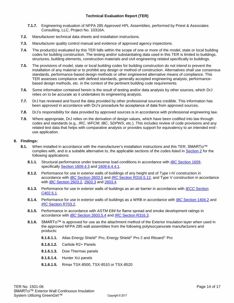
7.1.7. Engineering evaluation of NFPA 285 Approved HPL Assemblies, performed by Priest & Associates Consulting, LLC, Project No. 10316A.
7.2. Manufacturer technical data sheets and installation instructions.
7.3. Manufacturer quality control manual and evidence of approved agency inspections.
7.4. The product(s) evaluated by this TER falls within the scope of one or more of the model, state or local building codes for building construction. The testing and/or substantiating data used in this TER is limited to buildings, structures, building elements, construction materials and civil engineering related specifically to buildings.
7.5. The provisions of model, state or local building codes for building construction do not intend to prevent the installation of any material or to prohibit any design or method of construction. Alternatives shall use consensus standards, performance-based design methods or other engineered alternative means of compliance. This TER assesses compliance with defined standards, generally accepted engineering analysis, performance-based design methods, etc. in the context of the pertinent building code requirements.
7.6. Some information contained herein is the result of testing and/or data analysis by other sources, which DrJ relies on to be accurate as it undertakes its engineering analysis.
7.7. DrJ has reviewed and found the data provided by other professional sources credible. This information has been approved in accordance with DrJ’s procedure for acceptance of data from approved sources.
7.8. DrJ’s responsibility for data provided by approved sources is in accordance with professional engineering law.
7.9. Where appropriate, DrJ relies on the derivation of design values, which have been codified into law through codes and standards (e.g., IRC, WFCM, IBC, SDPWS, etc.). This includes review of code provisions and any related test data that helps with comparative analysis or provides support for equivalency to an intended end-use application.
8. Findings:
8.1. When installed in accordance with the manufacturer's installation instructions and this TER, SMARTci™ complies with, and is a suitable alternative to, the applicable sections of the codes listed in Section 2 for the following applications:
8.1.1. Structural performance under transverse load conditions in accordance with IBC Section 1609, specifically Section 1609.4.3 and 1609.6.4.4.1.
8.1.2. Performance for use in exterior walls of buildings of any height and of Type I-IV construction in accordance with IBC Section 2603.5 and IRC Section R316.5.12, and Type V construction in accordance with IBC Section 2603.2, 2603.3 and 2603.4.
8.1.3. Performance for use in exterior walls of buildings as an air barrier in accordance with IECC Section C402.5.1.
8.1.4. Performance for use in exterior walls of buildings as a WRB in accordance with IBC Section 1404.2 and IRC Section R703.2.
8.1.5. Performance in accordance with ASTM E84 for flame spread and smoke development ratings in accordance with IBC Section 2603.5.4 and IRC Section R316.3.
8.1.6. SMARTci™ is approved for use as the attachment method of the Exterior Insulation layer when used in the approved NFPA 285 wall assemblies from the following polyisocyanurate manufacturers and products:
8.1.6.1.1. Atlas Energy Shield Pro, Energy Shield Pro 2 and Rboard Pro
8.1.6.1.2. Carlisle R2+ Panels
8.1.6.1.3. Dow Thermax panels
8.1.6.1.4. Hunter Xci panels
8.1.6.1.5. Rmax TSX-8500, TSX-8510 or TSX-8520
Technical Evaluation Report (TER)
TER No. 1501-06 Page 15 of 17 SMARTci™ Exterior Wall Continuous Insulation System Utilizing GreenGirt™ Copyright © 2017
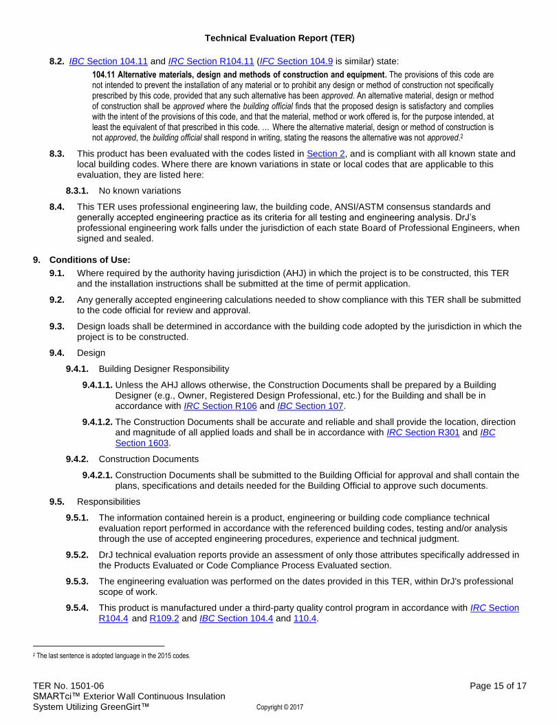
8.2. IBC Section 104.11 and IRC Section R104.11 (IFC Section 104.9 is similar) state:
104.11 Alternative materials, design and methods of construction and equipment. The provisions of this code are not intended to prevent the installation of any material or to prohibit any design or method of construction not specifically prescribed by this code, provided that any such alternative has been approved. An alternative material, design or method of construction shall be approved where the building official finds that the proposed design is satisfactory and complies with the intent of the provisions of this code, and that the material, method or work offered is, for the purpose intended, at least the equivalent of that prescribed in this code. … Where the alternative material, design or method of construction is not approved, the building official shall respond in writing, stating the reasons the alternative was not approved.2
8.3. This product has been evaluated with the codes listed in Section 2, and is compliant with all known state and local building codes. Where there are known variations in state or local codes that are applicable to this evaluation, they are listed here:
8.3.1. No known variations
8.4. This TER uses professional engineering law, the building code, ANSI/ASTM consensus standards and generally accepted engineering practice as its criteria for all testing and engineering analysis. DrJ’s professional engineering work falls under the jurisdiction of each state Board of Professional Engineers, when signed and sealed.
9. Conditions of Use:
9.1. Where required by the authority having jurisdiction (AHJ) in which the project is to be constructed, this TER and the installation instructions shall be submitted at the time of permit application.
9.2. Any generally accepted engineering calculations needed to show compliance with this TER shall be submitted to the code official for review and approval.
9.3. Design loads shall be determined in accordance with the building code adopted by the jurisdiction in which the project is to be constructed.
9.4. Design
9.4.1. Building Designer Responsibility
9.4.1.1. Unless the AHJ allows otherwise, the Construction Documents shall be prepared by a Building Designer (e.g., Owner, Registered Design Professional, etc.) for the Building and shall be in accordance with IRC Section R106 and IBC Section 107.
9.4.1.2. The Construction Documents shall be accurate and reliable and shall provide the location, direction and magnitude of all applied loads and shall be in accordance with IRC Section R301 and IBC Section 1603.
9.4.2. Construction Documents
9.4.2.1. Construction Documents shall be submitted to the Building Official for approval and shall contain the plans, specifications and details needed for the Building Official to approve such documents.
9.5. Responsibilities
9.5.1. The information contained herein is a product, engineering or building code compliance technical evaluation report performed in accordance with the referenced building codes, testing and/or analysis through the use of accepted engineering procedures, experience and technical judgment.
9.5.2. DrJ technical evaluation reports provide an assessment of only those attributes specifically addressed in the Products Evaluated or Code Compliance Process Evaluated section.
9.5.3. The engineering evaluation was performed on the dates provided in this TER, within DrJ's professional scope of work.
9.5.4. This product is manufactured under a third-party quality control program in accordance with IRC Section R104.4 and R109.2 and IBC Section 104.4 and 110.4.
2 The last sentence is adopted language in the 2015 codes.

Technical Evaluation Report (TER)
TER No. 1501-06 Page 16 of 17 SMARTci™ Exterior Wall Continuous Insulation System Utilizing GreenGirt™ Copyright © 2017
9.5.5. The actual design, suitability and use of this technical evaluation report for any particular building is the responsibility of the Owner or the Owner's authorized agent, and this TER shall be reviewed for code compliance by the Building Official.
9.5.6. The use of this TER is dependent on the manufacturer’s in-plant QC, the ISO/IEC 17020 third-party inspection process, proper installation per the manufacturer’s instructions, the Building Official’s inspection and any other code requirements that may apply to assure accurate compliance with the applicable building code.
10. Identification:
10.1. SMARTci™ Exterior Wall Continuous Insulation System described in this TER is identified by a label on the board or packaging material bearing the manufacturer’s name, product name, TER number, and other information to confirm code compliance.
10.2. Additional technical information can be found at SMARTciSystems.com.
11. Review Schedule:
11.1. This TER is subject to periodic review and revision. For the most recent version of this TER, visit drjengineering.org.
11.2. For information on the current status of this TER, contact DrJ Engineering.
Mission and Professional Responsibilities
Product Evaluation Policies
Product Approval – Building Code, Administrative Law and P.E. Law

Technical Evaluation Report (TER)
TER No. 1501-06 Page 17 of 17 SMARTci™ Exterior Wall Continuous Insulation System Utilizing GreenGirt™ Copyright © 2017
CBC Supplement to TER No. 1501-06
Issued: June 30, 2015
Updated: September 28, 2016
DIVISION: 07 00 00 – THERMAL AND MOISTURE PROTECTION Section: 07 20 00 – Thermal Insulation Section: 07 21 00 – Thermal Insulation Section: 07 27 23 – Board Product Air Barriers Section: 07 48 00 – Exterior Wall Assemblies REPORT HOLDER: A2P LLC. 959 Industrial Drive Allegan, MI. 49010 269-355-1818 866-858-5568 (fax) [email protected] [email protected] SMARTciSystems.com
EVALUATION SUBJECT: SMARTCI™ EXTERIOR WALL CONTINUOUS INSULATION SYSTEM SYSTEM UTILIZING GREENGIRT™
1. Report Purpose and Scope
Purpose: The purpose of this technical evaluation report (TER) supplement is to indicate that SMARTci™ Exterior Wall Continuous Insulation System, recognized in TER No. 1501-06, has also been evaluated for compliance with the codes noted below.
Applicable code editions:
2013 and 2016 California Building Code
2. Conclusions
SMARTci™ Exterior Wall Continuous Insulation System, described in Section 1 through 11 of TER No. 1501-06, comply with the California Building Code provided the design and installation are in accordance with the International Building Code® (IBC) provisions noted in the TER. This supplement is subject to renewal concurrently with TER No. 1501-06.