Embed Size (px)
Citation preview

SMART UNLOADING CONTROLLER AND PWM VALVEAPPLICATION GUIDE
1.0 Introduction . . . . . . . . . . . . . . . . . . . . . . . . 3
Functional Overview. . . . . . . . . . . . . . . . . . . . . . . 3Compressor Application . . . . . . . . . . . . . . . . . . . . 3Multiple Compressor Application . . . . . . . . . . . . . 4Specifications . . . . . . . . . . . . . . . . . . . . . . . . . . . . 4Compressor Envelope . . . . . . . . . . . . . . . . . . . . . 4
2.0 Component Description . . . . . . . . . . 5
Controller Input Signal . . . . . . . . . . . . . . . . . . . . . 5Power Supply Input . . . . . . . . . . . . . . . . . . . . . . . 5NC/NC Terminals . . . . . . . . . . . . . . . . . . . . . . . . . 5Discharge Temperature Sensor Input . . . . . . . . . 5Compressor Configuration Input . . . . . . . . . . . . . 6Comp/Alarm . . . . . . . . . . . . . . . . . . . . . . . . . . . . . 6Cylinder Head Fan Lead Wires . . . . . . . . . . . . . . 6AC IN . . . . . . . . . . . . . . . . . . . . . . . . . . . . . . . . . . 6Coil #1, Coil #2. . . . . . . . . . . . . . . . . . . . . . . . . . . 6Liquid Injection . . . . . . . . . . . . . . . . . . . . . . . . . . . 6
3.0 Controller Configuration (DIP Switches). . . . . . . . . . . . . . . . . . . . . . . . . . 6
4.0 Installation . . . . . . . . . . . . . . . . . . . . . . . . . 8
General Notes . . . . . . . . . . . . . . . . . . . . . . . . . . 8Mounting. . . . . . . . . . . . . . . . . . . . . . . . . . . . . . . 8Carlyle Smart Unloading Module Wiring Schematic . . . . . . . . . . . . . . . . . . . . . . . . 9
5.0 New Compressor Models . . . . . . . 11
6.0 Service and LED Tables . . . . . . . . . 13
7.0 Compressor Protection and Control . . . . . . . . . . . . . . . . . . . . . . . . . . . . . . . . 14
Temperature Control . . . . . . . . . . . . . . . . . . . . . 14Discharge Temperature Sensor Installation . . . 15Retrofit . . . . . . . . . . . . . . . . . . . . . . . . . . . . . . . 15
8.0 System Retrofit. . . . . . . . . . . . . . . . . . . 17
9.0 PWM Valve . . . . . . . . . . . . . . . . . . . . . . . . 19
Valve Installation and Operation . . . . . . . . . . . . 19PWM Valve Configuration. . . . . . . . . . . . . . . . . 20Service Table . . . . . . . . . . . . . . . . . . . . . . . . . . 21PWM Dimensions . . . . . . . . . . . . . . . . . . . . . . . 22Solenoid Coil Dimensions. . . . . . . . . . . . . . . . . 22
Contents

3
In refrigeration applications where the thermal load mayvary over a wide range, a means of precise capacity con-trol is always desirable for optimum system performance,while maintaining low energy consumption. In order tomeet these objectives, Carlyle has developed an innova-tive and efficient solution — the smart controller. Thisnew device meets the demand for precise suction pres-sure control by modulating system capacity for all low,medium, and high temperature applications that providesleading edge performance in compressor cycling reduc-tion, compressor life extension, and refrigeration systemenergy usage.
Functional Overview
The smart unloading controller allows continuous modu-lation of the compressor capacity using the steps ofmechanical unloading or Pulse Width Modulation (PWM)valve.
An analog output signal from the system rack controllerprovides a 0 to 10 vdc signal to the smart controller.Based on the signal, the smart controller continuouslymodulates the compressor unloader coils to deliver anequivalent linear change in the compressor capacity out-put to precisely meet the load demand. In addition, thesmart controller will control discharge temperature byoperating the accessory cylinder head fan and liquidinjection valve as required, maintaining safe and reliableoperation. If discharge temperature exceeds allowablelimits, the smart controller will automatically turn the com-pressor off to protect against compressor failure.
The smart controller is designed to operate the compres-sor unloaders or a PWM valve installed in the compres-sor’s suction line using PWM. As it does this, the smartcontroller will cycle the compressor unloader once every30 seconds between the loaded and unloaded positions.The relative duration of the loaded versus unloaded timescreates a time average flow rate from the compressorthat can be continuously varied. In turn, the time averageflow rate from the compressor allows it to more preciselymatch the compressor capacity to the system coolingdemand. For improved system functionality, all 6-cylindercompressors will have two unloader heads and all 4 cyl-inder compressors will have one unloader head. Thesmart controller will “switch” PWM control of the right cyl-inder head to the left cylinder head every 5,000 PWMcycles, and then back again for the 6-cylinder compres-sor models.
Compressor capacity modulation is achieved by energiz-ing the unloader solenoid coil for (t) seconds over a 30-second cycle (T). This PWM cycle (t) can be any durationof time between zero and 30 seconds (see Fig. 1). Forexample, if the smart controller receives a load demandsignal of 1 vdc, per Fig. 2 this will result in a compressorcapacity of 90%. To achieve the 90% compressor capac-ity, the smart controller will energize the unloader coil for9 seconds (t), and then de-energize the unloader coil for21 seconds. This 30 second PWM cycle (T) will notchange unless the system’s vdc demand signal changes.
Compressor Application
The smart controller is designed to operate with 06D,06E, and 06M compressor models for all low, mediumand high temperature applications. If using the smartcontroller in combination with the PWM valve, see addi-tional information in Section 9.0.
Fig. 1 — Pulse Width Modulation Cycle
Fig. 2 — Compressor Capacity at 90%
1.0 Introduction
4
Multiple Compressor Application
The smart controller was designed specifically for rackrefrigeration systems where multiple compressors sharea common suction group and operate in tandem. Follow-ing these simple guidelines will ensure the correct com-pressor is selected for smart unloading for a multiplecompressor application.
• The compressor selected for smart unloading shouldbe designated as the lead compressor for the suctiongroup.
• The compressor selected for smart unloading shouldbe the first compressor on and the last compressoroff. Manual staging of the rack compressors is rec-ommended, ensuring the smart compressor is notturned off out of sequence by the rack controller.
• Apply smart unloading to only one compressor persuction group.
• The smart unloading capacity modulation range canbe applied to cover the capacity gaps between com-pressor steps. Choosing the compressor with thesmallest capacity modulation range that coversthese capacity gaps is recommended.
• A control signal (0 to 10 vdc) from the rack controlleris a required input to the smart controller. Work withthe rack controller manufacturer for implementationwith the manufacturer’s software. See the graphical
profile of compressor capacity versus control signalfor the application shown in Section 3.0.
• A rack controller that has PID capability is recom-mended, providing the best control, but is notrequired.
• Consult your Carlyle Applications Engineer for assis-tance in applying smart unloading.
Specifications
Dimensions: 3.43 in. W x 1.57 in. H x 3.23 in. D (87mm Wx 40mm H x 82mm D)
Supply AC: 24 vac ± 10%, 50/60 Hz, 5 VA
Operating Range: -22 F to 158 F (-30 C to 70 C) Ambient
Enclosure Protection: IP20
Compressor Envelope
The SST/SDT (Saturated Suction Temperature/SaturatedDischarge Temperature) compressor operating envelopefor all smart controller 06D/E compressors are the sameas the standard 06D/E compressor for the applicablerefrigerant. The cylinder head fan, return gas tempera-ture, and oil temperature requirements are the same asthe standard 06D/E compressor.

5
2.0 Component Description
Controller Input Signal
The smart controller (see Fig. 3) receives a 0 to 10 vdcinput signal from the system’s rack controller. This signalis inversely proportional to the capacity demand requiredfrom the compressor. A 0 vdc demand signal representsa 100% capacity output from the compressor. The mini-mum demand voltage signal (compressor fully unloaded),depends on the compressor configuration selected by thesmart controller DIP switches (see Section 3.0).
Power Supply Input
The smart controller requires a 24 vac (±10%), 50/60 Hzsource to power the module. The maximum continuousrating is 5 VA. Control power should be isolated with atransformer from the main power supply.
NC/NC Terminals
The two NC terminals are currently not used and provideno functionality at this time. Do not use.
Discharge Temperature Sensor Input
The smart controller has the capability to monitor andcontrol the compressor’s refrigerant discharge tempera-ture. The thermistor input range is -22 F to 320 F, accu-racy of -3%/+0%, with a maximum allowable sensorcable length of 30 ft. The smart controller will process theinput from the discharge temperature sensor and operatethe compressor’s cylinder head fan and liquid injectionvalve as required to control compressor discharge tem-perature below 230 F. Every smart controller comeswith a 1000 ohm resistor installed. Remove only ifinstalling the Carlyle discharge temperature sensor
ControllerInputSignal
PowerSupplyInput
DischargeTemperature
SensorInput
CompressorConfiguration
Input(Low, Medium,
High Temp)
LiquidInjectionOutputUnloader
CoilOutput
Cylinder HeadFan Lead Wire(208-230/460v)
AC In(115/208-230V)
CompressorStart
Circuit
Fig. 3 — Smart Controller

6
for discharge temperature control; otherwise do notremove the resistor.
Compressor Configuration Input
The smart controller is configurable for all 06D, 06E, and06M compressor models by simply adjusting the onboardDIP switches. The DIP switches configure the compres-sor for Low or Medium/High temperature application andset the compressor’s capacity modulation range profile.See Section 3.0 for configuration details. Controllerpower must be cycled off/on if the configuration switchesare changed during system operation for that change totake effect.
Comp/Alarm
The compressor contactor output is a relay output. Therelay operating voltage is 24 to 240 vac with a maximumcontinuous current of 2.5 amps (600 VA). The compres-sor COMP contactor will open when any of the followingconditions exist:
• Loss of 24 VAC supply power
• Discharge temperature sensor failure, discharge temperature >295 F
• The input demand voltage is > 8.0 vdc.
The Comp/Alarm contactor should be wired into thecompressor’s control power circuit if the Carlyle dis-charge temperature sensor is being used to controlcompressor discharge temperature. This will ensurethe compressor will shut down if discharge tempera-ture exceeds 295 F or sensor fails. The triac output forCoil 1, Coil 2, and the LIV (Liquid Injection Valve) will
open, disabling the unloader valves and liquid injectionvalve if the Comp/Alarm contactor is opened.
Cylinder Head Fan Lead Wires
The smart controller has two 6-in. lead wires for wiring tothe compressor’s cylinder head fan. The smart controllerwill energize/de-energize the internal cylinder head fanrelay as required to maintain discharge temperaturesbelow 220 F. The lead wires are rated for 230/460 vacwith a maximum continuous rating of 2.5 amps.
AC IN
Line voltage input to provide power to the unloader sole-noid coils and the liquid injection solenoid coil. Rated for115/208-230 vac with a maximum continuous rating of 30VA.
Coil #1, Coil #2
The unloader solenoid output is a triac output. The triac israted for 115/208-230 vac with a maximum continuousrating of 30 VA. The smart controller energizes theunloader solenoid coil in an on/off sequence per the 0 to10 vdc analog input signal received by the smart control-ler.
Liquid Injection
The liquid injection solenoid output is a triac output. Thetriac is rated for 115/208-230 vac with a maximum contin-uous rating of 30 VA. The smart controller will energizethe liquid injection solenoid as required to provide com-pressor motor cooling and maintain compressor dis-charge below 230 F.
3.0 Controller Configuration (DIP Switch)The smart controller’s configuration switch is a manualswitch the operator must configure before powering upthe unit. The configuration DIP switch has 4 positions (A,B, C, D) and corresponds to the type of compressor andcompressor modulation range. The table below and Fig.4 and 5 show the DIP switch positions to correctly config-
ure the smart controller to the smart compressor. Theconfiguration switch can be positioned at any time whilethe smart controller is off.
CONFIGURATION DIP SWITCH POSITION
COMPRESSOR MODELS
# OF COMPRESSOR
CYLINDERS# OF UNLOADERS ON COMPRESSOR
MODULATION RANGE
ELECTRICAL SCHEMATIC
A 06D, 06E 6 2 33% - 100% Figure 7
B06D, 06E 6 2 67% - 100% Figure 7
06M 3 1 67% - 100% Figure 8
C06D, 06E 4 1 50% - 100% Figure 8
06D, 06CC, 06M 3, 4, or 6 PWM Valve 20% - 100% Figure 8
D All 3, 4, or 6 None None NA

7
Position A
Position C
1 stage of Unloading
67-100%
PWM Valve 20-100%
1 stage of Unloading 50-100%
No Capacity Modulation Compressor Monitoring
and Protection only
2 stages of Unloading
33-100%
Position B Position DFig. 4 — Smart Controller Configuration (DIP Switches)
4 Cylinder, 1 Stage Unloader
Fig. 5 — Smart Controller Configuration (DIP Switches), Compressor Capacity
8
4.0 InstallationGeneral Notes1. Inspect the smart controller for shipping damage to
the body, electrical connection points, and lead wires.
2. For new compressor production verify the compres-sor chosen for smart unloading has a “Y” in the 13thdigit for 06D models, a “Y” in the 5th digit for 06Emodels, and a “Y” in the 10th digit for 06M models(see Section 5.0). If no “Y” is identified in the com-pressor model nomenclature, contact Carlyle Appli-cation Engineering. The “Y” designation defines thecompressor as a smart compressor.
3. If retrofitting an existing field compressor for SmartUnloading, the compressor will require the installa-tion of two new smart unloading cylinder heads andtwo new unloader solenoid coils. A horizontal line willbe stamped on the face of both unloader cylinderheads to identify that the heads are smart unloadingheads. See Section 8.0 for guidelines and parts list-ing.
4. The smart compressor must have two suction cut-offunloader heads installed on all 06D and 06E 6-cylin-der compressors and one suction cut-off unloaderhead installed on all 06D and 06E 4-cylinder com-pressors.
5. The smart controller will only pulse width modulate(PWM) 1 unloader at a time. Every 5,000 cycles thesmart controller will automatically “switch” PWM con-trol of the right cylinder head to the left cylinder head,then back again for 6-cylinder compressor models.
6. All 06D and 06E 4-cylinder compressor models willhave only 1 unloader cylinder head.
7. The smart controller comes with a 1000-ohm resistorinstalled in the discharge temperature sensor input.Remove only if installing the Carlyle discharge tem-perature sensor for discharge temperature control;otherwise do not remove the resistor.
Mounting
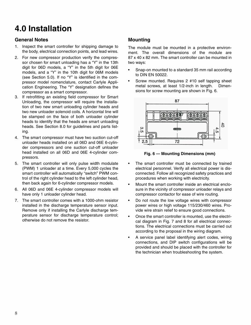
The module must be mounted in a protective environ-ment. The overall dimensions of the module are87 x 40 x 82 mm. The smart controller can be mounted intwo ways:
• Snap-on mounted to a standard 35 mm rail accordingto DIN EN 50022.
• Screw mounted. Requires 2 #10 self tapping sheetmetal screws, at least 1/2-inch in length. Dimen-sions for screw mounting are shown in Fig. 6.
• The smart controller must be connected by trainedelectrical personnel. Verify all electrical power is dis-connected. Follow all recognized safety practices andprocedures when working with electricity.
• Mount the smart controller inside an electrical enclo-sure in the vicinity of compressor unloader relays andcompressor contactor for ease of wire routing.
• Do not route the low voltage wires with compressorpower wires or high voltage 115/230/460 wires. Pro-vide wire strain relief to ensure good connections.
• Once the smart controller is mounted, use the electri-cal diagram in Fig. 7 and 8 for all electrical connec-tions. The electrical connections must be carried outaccording to the proposal in the wiring diagram.
• A service panel label identifying alert codes, wiringconnections, and DIP switch configurations will beprovided and should be placed with the controller forthe technician when troubleshooting the system.
Fig. 6 — Mounting Dimensions (mm)

9
Carlyle Smart Unloading Module Wiring Schematic
MC ylinder H ead F an
230 /460 Vac Input
LiquidInjectionSolenoid
U nloader C oil 1
U nloader C oil 2
S M A R T U n load ing M odu le
T d is c h a r g eSensor
PT 1000 D ischargeGN D T em perature
0 ..10 VD C D em andGN D Signal
24 Vac
C om pressor M otor
24 Vac
F use
C om pressorC ontactor
Protection D evicesInstalled H ere
115 / 230 Vac C ontrol Pow er
L N
2 am p 120 V1 am p 240 V
F use( tim e delay )
Alternate½ am p F use
Alternate½ am p F use
Alternate½ am p F use
C ontrol Voltage
C om p
Injection
C oil 1
C oil 2
W ire Leads
AC in
R ackC ontro ller
C om pressor Alarm Status Input
C om pressor C apacityOutput (0-10 Vdc)
C om pressor Star t /Stop
Isolation R elay
C om pressor Selector
ON
1 2
LED Indicator
Isolation R elay
120 /208 -230 Vac Input
Fig. 7 — Electrical Schematic, Compressors with 2 Unloading Heads
NOTES:
1. The smart controller must be configured based on thetype of compressor it is controlling. See Section 3.0 forconfiguration details.
2. The compressor is loaded when the unloader solenoidcoil is de-energized and unloaded when the solenoid coilis energized.
3. The power for the compressor contactor, unloader coils,and liquid injection solenoid may be either 115 vac or 230vac. All components must be of the same voltage. Fusingfor this should be a 2 amp-120V or 1 amp-240V timedelay fuse. Alternately, the components may be fusedindividually with ½ amp fuses.
4. The compressor COMP contactor will open when any ofthe following conditions exist: loss of 24 vac supply power,discharge temperature sensor failure, discharge tempera-ture >295 F, or the input demand voltage is > 8.0 vdc. TheCOMP contactor should be wired into the compressor’s
control power circuit if the Carlyle discharge temperaturesensor is being used to control compressor dischargetemperature. This will ensure the compressor will shutdown if discharge temperature exceeds 295 F or the sen-sor fails. The triac output for Coil 1, Coil 2, and the LIV willopen, disabling the unloader valves and liquid injectionvalve if the COMP contactor is opened.
5. The smart controller cylinder head fan lead wires may beeither single phase 230 vac or 460 vac. The cylinder headfan relay will open at a loss of 24 vac supply power, dis-charge temperature sensor failure, or input demand volt-age > 8.0 vdc. Upon a compressor discharge temperaturetrip ( > 295 F) the cylinder head fan relay will stay closed.Typically the compressor’s cylinder head fan will shutdown when the compressor is off, but with the smart con-troller the fan will still operate to reduce discharge temper-ature below 230 F so the compressor will auto restartfollowing a 5-minute time delay.
10
MC ylinder H ead F an
230 /460 Vac Input
LiquidInjectionSolenoid
U nloader C oil 1
S M A R T U n load ing M odu le
T d is c h a r g eSensor
PT 1000 D ischargeGN D T em perature
0 ..10 VD C D em andGN D Signal
24 Vac
C om pressor M otor
24 Vac
F use
C om pressorC ontactor
Protection D evicesInstalled H ere
115 / 230 Vac C ontrol Pow er
L N
2 am p 120 V1 am p 240 V
F use( tim e delay )
Alternate½ am p F use
Alternate½ am p F use
C ontrol Voltage
C om p
Injection
C oil 1
C oil 2
W ire Leads
AC in
R ackC ontro ller
C om pressor Alarm Status Input
C om pressor C apacityOutput (0-10 Vdc)
C om pressor Star t /Stop
Isolation R elay
C om pressor Selector
ON
1 2
LED Indicator
Isolation R elay
120 /208 -230 Vac Input
Do not use Coil #2
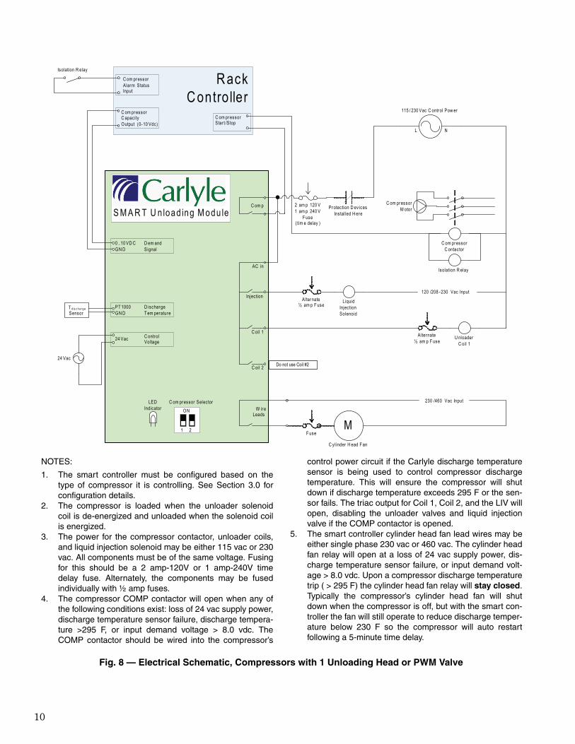
Fig. 8 — Electrical Schematic, Compressors with 1 Unloading Head or PWM Valve
NOTES:
1. The smart controller must be configured based on thetype of compressor it is controlling. See Section 3.0 forconfiguration details.
2. The compressor is loaded when the unloader solenoidcoil is de-energized and unloaded when the solenoid coilis energized.
3. The power for the compressor contactor, unloader coils,and liquid injection solenoid may be either 115 vac or 230vac. All components must be of the same voltage. Fusingfor this should be a 2 amp-120V or 1 amp-240V timedelay fuse. Alternately, the components may be fusedindividually with ½ amp fuses.
4. The compressor COMP contactor will open when any ofthe following conditions exist: loss of 24 vac supply power,discharge temperature sensor failure, discharge tempera-ture >295 F, or input demand voltage > 8.0 vdc. TheCOMP contactor should be wired into the compressor’s
control power circuit if the Carlyle discharge temperaturesensor is being used to control compressor dischargetemperature. This will ensure the compressor will shutdown if discharge temperature exceeds 295 F or the sen-sor fails. The triac output for Coil 1, Coil 2, and the LIV willopen, disabling the unloader valves and liquid injectionvalve if the COMP contactor is opened.
5. The smart controller cylinder head fan lead wires may beeither single phase 230 vac or 460 vac. The cylinder headfan relay will open at a loss of 24 vac supply power, dis-charge temperature sensor failure, or input demand volt-age > 8.0 vdc. Upon a compressor discharge temperaturetrip ( > 295 F) the cylinder head fan relay will stay closed.Typically the compressor’s cylinder head fan will shutdown when the compressor is off, but with the smart con-troller the fan will still operate to reduce discharge temper-ature below 230 F so the compressor will auto restartfollowing a 5-minute time delay.
11
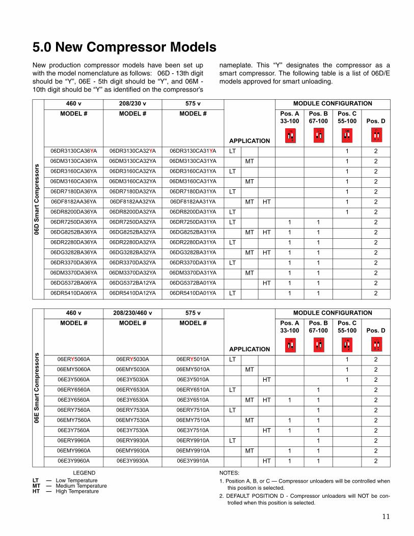
5.0 New Compressor ModelsNew production compressor models have been set upwith the model nomenclature as follows: 06D - 13th digitshould be “Y”, 06E - 5th digit should be “Y”, and 06M -10th digit should be “Y” as identified on the compressor’s
nameplate. This “Y” designates the compressor as asmart compressor. The following table is a list of 06D/Emodels approved for smart unloading.
LEGEND NOTES:
1. Position A, B, or C — Compressor unloaders will be controlled whenthis position is selected.
2. DEFAULT POSITION D - Compressor unloaders will NOT be con-trolled when this position is selected.
06D
Sm
art
Co
mp
res
sors
460 v 208/230 v 575 v
APPLICATION
MODULE CONFIGURATION
MODEL # MODEL # MODEL # Pos. A33-100
Pos. B67-100
Pos. C55-100 Pos. D
06DR3130CA36YA 06DR3130CA32YA 06DR3130CA31YA LT 1 2
06DM3130CA36YA 06DM3130CA32YA 06DM3130CA31YA MT 1 2
06DR3160CA36YA 06DR3160CA32YA 06DR3160CA31YA LT 1 2
06DM3160CA36YA 06DM3160CA32YA 06DM3160CA31YA MT 1 2
06DR7180DA36YA 06DR7180DA32YA 06DR7180DA31YA LT 1 2
06DF8182AA36YA 06DF8182AA32YA 06DF8182AA31YA MT HT 1 2
06DR8200DA36YA 06DR8200DA32YA 06DR8200DA31YA LT 1 2
06DR7250DA36YA 06DR7250DA32YA 06DR7250DA31YA LT 1 1 2
06DG8252BA36YA 06DG8252BA32YA 06DG8252BA31YA MT HT 1 1 2
06DR2280DA36YA 06DR2280DA32YA 06DR2280DA31YA LT 1 1 2
06DG3282BA36YA 06DG3282BA32YA 06DG3282BA31YA MT HT 1 1 2
06DR3370DA36YA 06DR3370DA32YA 06DR3370DA31YA LT 1 1 2
06DM3370DA36YA 06DM3370DA32YA 06DM3370DA31YA MT 1 1 2
06DG5372BA06YA 06DG5372BA12YA 06DG5372BA01YA HT 1 1 2
06DR5410DA06YA 06DR5410DA12YA 06DR5410DA01YA LT 1 1 2
06E
Sm
art
Co
mp
ress
ors
460 v 208/230/460 v 575 v
APPLICATION
MODULE CONFIGURATION
MODEL # MODEL # MODEL # Pos. A33-100
Pos. B67-100
Pos. C55-100 Pos. D
06ERY5060A 06ERY5030A 06ERY5010A LT 1 2
06EMY5060A 06EMY5030A 06EMY5010A MT 1 2
06E3Y5060A 06E3Y5030A 06E3Y5010A HT 1 2
06ERY6560A 06ERY6530A 06ERY6510A LT 1 2
06E3Y6560A 06E3Y6530A 06E3Y6510A MT HT 1 1 2
06ERY7560A 06ERY7530A 06ERY7510A LT 1 2
06EMY7560A 06EMY7530A 06EMY7510A MT 1 1 2
06E3Y7560A 06E3Y7530A 06E3Y7510A HT 1 1 2
06ERY9960A 06ERY9930A 06ERY9910A LT 1 2
06EMY9960A 06EMY9930A 06EMY9910A MT 1 1 2
06E3Y9960A 06E3Y9930A 06E3Y9910A HT 1 1 2
LT — Low TemperatureMT — Medium TemperatureHT — High Temperature

12
LEGEND NOTE: 06MR and 06MM models are not released for production.
06M
Sm
art
Co
mp
ress
ors
460 v 208/230 v 575 v
APPLICATION
MODULE CONFIGURATION
MODEL # MODEL # MODEL # Pos. A33-100
Pos. B67-100
Pos. C55-100 Pos. D
06MR015E0Y42 06MR015E0Y22 06MR015E0Y52 LT 1 2
06MR018E0Y42 06MR018E0Y22 06MR018E0Y52 LT 1 2
06MR021E0Y42 06MR021E0Y22 06MR021E0Y52 LT 1 2
06MR024E0Y42 06MR024E0Y22 06MR024E0Y52 LT 1 2
06MM015E0Y42 06MM015E0Y22 06MM015E0Y52 MT 1 2
06MM018E0Y42 06MM018E0Y22 06MM018E0Y52 MT 1 2
06MM021E0Y42 06MM021E0Y22 06MM021E0Y52 MT 1 2
06MM024E0Y42 06MM024E0Y22 06MM024E0Y52 MT 1 2
06MA015E0Y42 06MA015E0Y22 06MA015E0Y52 MT HT 1 2
06MA018E0Y42 06MA018E0Y22 06MA018E0Y52 MT HT 1 2
06MA021E0Y42 06MA021E0Y22 06MA021E0Y52 MT HT 1 2
06MA024E0Y42 06MA024E0Y22 06MA024E0Y52 MT HT 1 2
LT — Low TemperatureMT — Medium TemperatureHT — High Temperature

13
6.0 Service and LED TablesThe Service and LED tables allow the Installer and/orService Technician the ability to verify the smart control-ler is functioning properly once installation is completeand the refrigeration system is ready for service. Based
on the voltage input signal to the smart controller, thePWM cycle and LED status of the smart compressor canbe checked per the tables.
Service Table
06D/E COMPRESSOR CAPACITY
POSITION A POSITION B POSITION C
6 CYLINDER COMPRESSOR
3 AND 6 CYLINDERCOMPRESSOR
4 CYLINDER COMPRESSOR
DEMAND SIGNAL PERCENTAGE
CAPACITY MODULATION 33 - 100%
CAPACITY MODULATION 67 - 100%
CAPACITY MODULATION 50 - 100%
vdc A B C
SecondsEnergized
Seconds Energized
Seconds Energized
Coil #1 Coil #2 Lead Coil Coil #1
0.00 100 100 100 0.0 0.0 0.0 0.0
0.50 95 95 95 4.5 0.0 4.5 3.0
1.00 90 90 90 9.0 0.0 9.0 6.0
1.50 85 85 85 13.5 0.0 13.5 9.0
2.00 80 80 80 18.0 0.0 18.0 12.0
2.50 75 75 75 22.5 0.0 22.5 15.0
3.00 70 70 70 27.0 0.0 27.0 18.0
3.30 67 67 67 30.0 0.0 30.0 19.7
3.40 66 67 66 0.0 30.0 30.0 21.4
3.50 65 67 65 1.5 30.0 30.0 21.0
4.00 60 67 60 6.0 30.0 30.0 24.0
4.50 55 67 55 10.5 30.0 30.0 27.0
5.00 50 67 50 15.0 30.0 30.0 30.0
5.50 45 67 50 19.5 30.0 30.0 30.0
6.00 40 67 50 24.0 30.0 30.0 30.0
6.50 35 67 50 28.5 30.0 30.0 30.0
6.70 33 67 50 30.0 30.0 30.0 30.0
7.00 33 67 50 30.0 30.0 30.0 30.0
7.50 33 67 50 30.0 30.0 30.0 30.0
8.00 33 67 50 30.0 30.0 30.0 30.0

14
7.0 Compressor Protection and ControlThe smart controller provides improved temperature con-trol and protection. The module is equipped with a dis-charge temperature sensor input allowing on-demandengagement of the liquid injection valve and cylinderhead fan as follows:
Temperature Control
Increasing Discharge Temperature:
220 F — Cylinder Head Fan ON
230 F — Injection Valve OPEN
295 F — Compressor SHUTDOWN alarm
Decreasing Discharge Temperature:
(See Fig. 9)
230 F — Compressor alarm/comp RESET
210 F — Injection Valve CLOSED
175 F — Cylinder Head Fan OFF
Smart Controller LED Indicator Status Lights and Output Status
CONDITION DESCRIPTIONLED
STATUSCOMP
CONTACTORCOIL 1 & 2 OUTPUT
LIQUID INJECTION
VALVE INJECTION
OUTPUT
CYLINDER HEAD FAN CONTROL
Compressor ON. Demand Signal < 8 vdc
Compressor is operating under normal modulation control.
GREEN Constant Blinking
Closed PWM as Required
As Required As Required
Demand signal > 8 vdc There are no active alarm states and the controller assumes compressor is off due to no demand for cooling.
GREEN Solid
Open Disabled. No PWM Control.
Disabled Disabled
High DischargeTemperature > 295 F
Compressor is shut down due to high discharge gas temperature. Will auto reset, compressor ON, in 5 minutes if discharge temperature < 230 F and demand signal < 8 vdc.
RED2 blinks &
pause
Open Disabled. No PWM Control.
Disabled Functional/Operational
Discharge Gas Temperature Sensor Failure
Compressor is shut down under an alarm for discharge gas temperature sensor fail-ure. Manual reset required.
REDLong
blink, two short
blinks & pause
Open Disabled. No PWM Control.
Disabled Disabled
Compressor OFF.Module Failure
Invalid value at the demand input or module internal failure.
REDConstant
Blink
Open Disabled. No PWM Control.
Disabled Disabled
Fig. 9 — Discharge Temperatures
15
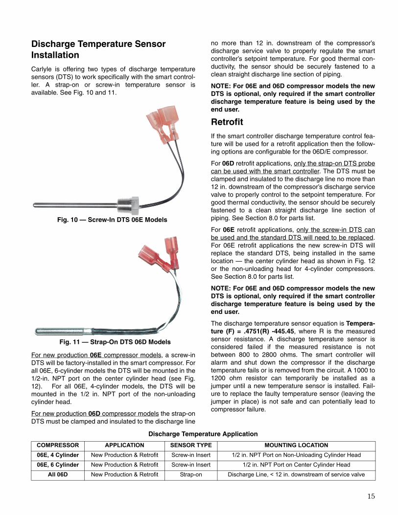
Discharge Temperature Sensor InstallationCarlyle is offering two types of discharge temperaturesensors (DTS) to work specifically with the smart control-ler. A strap-on or screw-in temperature sensor isavailable. See Fig. 10 and 11.
For new production 06E compressor models, a screw-inDTS will be factory-installed in the smart compressor. Forall 06E, 6-cylinder models the DTS will be mounted in the1/2-in. NPT port on the center cylinder head (see Fig.12). For all 06E, 4-cylinder models, the DTS will bemounted in the 1/2 in. NPT port of the non-unloadingcylinder head.
For new production 06D compressor models the strap-onDTS must be clamped and insulated to the discharge line
no more than 12 in. downstream of the compressor’sdischarge service valve to properly regulate the smartcontroller’s setpoint temperature. For good thermal con-ductivity, the sensor should be securely fastened to aclean straight discharge line section of piping.
NOTE: For 06E and 06D compressor models the newDTS is optional, only required if the smart controllerdischarge temperature feature is being used by theend user.
RetrofitIf the smart controller discharge temperature control fea-ture will be used for a retrofit application then the follow-ing options are configurable for the 06D/E compressor.
For 06D retrofit applications, only the strap-on DTS probecan be used with the smart controller. The DTS must beclamped and insulated to the discharge line no more than12 in. downstream of the compressor’s discharge servicevalve to properly control to the setpoint temperature. Forgood thermal conductivity, the sensor should be securelyfastened to a clean straight discharge line section ofpiping. See Section 8.0 for parts list.
For 06E retrofit applications, only the screw-in DTS canbe used and the standard DTS will need to be replaced.For 06E retrofit applications the new screw-in DTS willreplace the standard DTS, being installed in the samelocation — the center cylinder head as shown in Fig. 12or the non-unloading head for 4-cylinder compressors.See Section 8.0 for parts list.
NOTE: For 06E and 06D compressor models the newDTS is optional, only required if the smart controllerdischarge temperature feature is being used by theend user.
The discharge temperature sensor equation is Tempera-ture (F) = .4751(R) -445.45, where R is the measuredsensor resistance. A discharge temperature sensor isconsidered failed if the measured resistance is notbetween 800 to 2800 ohms. The smart controller willalarm and shut down the compressor if the dischargetemperature fails or is removed from the circuit. A 1000 to1200 ohm resistor can temporarily be installed as ajumper until a new temperature sensor is installed. Fail-ure to replace the faulty temperature sensor (leaving thejumper in place) is not safe and can potentially lead tocompressor failure.
Discharge Temperature Application
Fig. 10 — Screw-In DTS 06E Models
Fig. 11 — Strap-On DTS 06D Models
COMPRESSOR APPLICATION SENSOR TYPE MOUNTING LOCATION
06E, 4 Cylinder New Production & Retrofit Screw-in Insert 1/2 in. NPT Port on Non-Unloading Cylinder Head
06E, 6 Cylinder New Production & Retrofit Screw-in Insert 1/2 in. NPT Port on Center Cylinder Head
All 06D New Production & Retrofit Strap-on Discharge Line, < 12 in. downstream of service valve
16
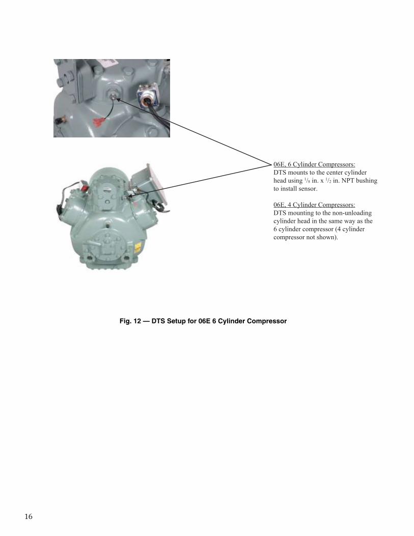
06E, 6 Cylinder Compressors:DTS mounts to the center cylinderhead using 1/8 in. x 1/2 in. NPT bushingto install sensor.
06E, 4 Cylinder Compressors:DTS mounting to the non-unloadingcylinder head in the same way as the 6 cylinder compressor (4 cylindercompressor not shown).
Fig. 12 — DTS Setup for 06E 6 Cylinder Compressor
17
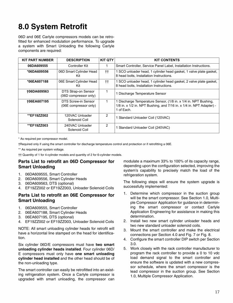
8.0 System Retrofit06D and 06E Carlyle compressors models can be retro-fitted for enhanced modulation performance. To upgradea system with Smart Unloading the following Carlylecomponents are required:
* As required per compressor model.
†Required only if using the smart controller for discharge temperature control and protection or if retrofitting a 06E.
** As required per system voltage.
†† Quantity of 1 for 4-cylinder models and quantity of 2 for 6-cylinder models.
Parts List to retrofit an 06D Compressor forSmart Unloading
1. 06DA609555, Smart Controller2. 06DA609556, Smart Cylinder Heads3. 06DA609563, DTS (optional)4. EF19ZZ002 or EF19ZZ003, Unloader Solenoid Coils
Parts List to retrofit an 06E Compressor forSmart Unloading
1. 06DA609555, Smart Controller2. 06EA607188, Smart Cylinder Heads3. 06EA607195, DTS (optional)4. EF19ZZ002 or EF19ZZ003, Unloader Solenoid Coils
NOTE: All smart unloading cylinder heads for retrofit willhave a horizontal line stamped on the head for identifica-tion.
Six cylinder 06D/E compressors must have two smartunloading cylinder heads installed. Four cylinder 06D/E compressors must only have one smart unloadingcylinder head installed and the other head should be ofthe non-unloading type.
The smart controller can easily be retrofitted into an exist-ing refrigeration system. Once a Carlyle compressor isupgraded with smart unloading, the compressor can
modulate a maximum 33% to 100% of its capacity range,depending upon the configuration selected, improving thesystem’s capability to precisely match the load of therefrigeration system.
The following steps will ensure the system upgrade issuccessfully implemented:
1. Determine which compressor in the suction groupwill be the smart compressor. See Section 1.0, Multi-ple Compressor Application for guidance in determin-ing the smart compressor or contact CarlyleApplication Engineering for assistance in making thisdetermination.
2. Install two new smart cylinder unloader heads andtwo new standard unloader solenoid coils.
3. Mount the smart controller and make the electricalconnections per Section 4.0 and Fig. 7 or Fig. 8.
4. Configure the smart controller DIP switch per Section3.0.
5. Work closely with the rack controller manufacturer toprogram the rack controller to provide a 0 to 10 vdcload demand signal to the smart controller andensure the software is updated with a new compres-sor schedule, where the smart compressor is thelead compressor in the suction group. See Section1.0, Multiple Compressor Application.
KIT PART NUMBER DESCRIPTION KIT QTY KIT CONTENTS
06DA609555 Controller Kit 1 Smart Controller, Service Panel Label, Installation Instructions.
*06DA609556 06D Smart Cylinder Head Kit
†† 1 SCO unloader head, 1 cylinder head gasket, 1 valve plate gasket, 8 head bolts, Installation Instructions.
*06EA607188 06E Smart Cylinder Head Kit
†† 1 SCO unloader head, 1 cylinder head gasket, 2 valve plate gasket, 8 head bolts, Installation Instructions.
†06DA609563 DTS Strap-on Sensor(06D compressor only)
11 Discharge Temperature Sensor
†06EA607195 DTS Screw-in Sensor (06E compressor only)
1 1 Discharge Temperature Sensor, (1/8 in. x 1/4 in. NPT Bushing,1/8 in. x 1/2 in. NPT Bushing, and 7/16 in. x 1/4 in. NPT Adapter) - 1 of Each.
**EF19ZZ002 120VAC Unloader Solenoid Coil
21 Standard Unloader Coil (120VAC)
**EF19ZZ003 240VAC Unloader Solenoid Coil
21 Standard Unloader Coil (240VAC)

18
Replace both the left and right bank standard cylinderheads (6-cylinder only) with new smart Unloading cylin-der heads and new standard solenoid coils as shown inFig. 13.
06E, 6-Cylinder Compressor 06D, 6-Cylinder Compressor
SmartCylinderHeads
SolenoidCoils
SolenoidCoils
SmartCylinderHeads
Fig. 13 — Smart Unloading Cylinder Heads and New Standard Solenoid Coils

19
9.0 PWM ValveThe Carlyle pulse width modulation (PWM) valve is arobust high cycle capacity control valve designed to mod-ulate and control compressor capacity from 20% to 100%of compressor full load. In conjunction with the Carlylesmart controller, the PWM valve can easily be controlledto provide a linear incremental step change to compres-sor capacity. The PWM valve is controlled in the samemanner as the unloader head on a compressor, by usinga 30-second PWM control signal from the smart control-ler (see Functional Overview on page 3).
The Carlyle PWM valve (Fig. 14) is designed to work spe-cifically with the Carlyle 06D, 06CC, and 06M compressormodels for all low, medium, and high temperature appli-cations.
NOTE: When applying the smart controller with the PWMvalve the standard non-unloading compressor modelsshould be used and therefore the compressor will nothave a “Y” in the compressor model number. See thePWM Valve Dimensions section for correct usage.
Valve Installation and Operation• Inspect the PWM valve for any shipping damage and
verify the correct part number is called out on the valve.
• The PWM valve installs in the suction line of the com-pressor. The valve should be installed along a straight tubing run leading to the inlet of the compres-sor's suction service valve.
• The PWM valve must be mounted in a horizontal position so the solenoid coil valve stem is in the verti-cal position. Mounting in any other direction or imposing a tilt angle may result in valve malfunction. See Fig. 15.
• The PWM valve has 1-1/8 ODF connections for brazed installation. Do not braze the valve in-place with the solenoid coil installed, and always wrap the valve in wet rags to prevent any heat damage to the valve during the brazing process.
• The PWM valve has a refrigerant flow directional arrow located on the top of the valve to ensure cor-rect horizontal orientation. See Fig. 16.
• The PWM valve is a normally closed valve and requires a solenoid coil to be energized to open the valve. The PWM valve is equipped with a manual lift-ing stem, when front seated, will force the valve fully open (see page 22 PWM dimensional drawing).
• Once the PWM valve is brazed in-place, the solenoid coil can be installed. Use Carlyle solenoid coil 8ADB000688 or 8ADB000689. These coils have been qualified and life-cycle tested with the PWM valve. The use of any other coil is not approved by Carlyle.
• The PWM valve solenoid coil should wire back to the Smart Control, Coil #1 position as shown in electrical schematic Fig. 8.
• The PWM valve should not be cycled by the smart controller when the compressor is not operating. Power to the PWM valve solenoid coil should be
Fig. 14 — PWM Valve PN 8ADB000690 and 8ADB000907
SOLENOID COILP/N 8ADB000688 (240 vac)P/N 8ADB000689 (120 vac)
PWM VALVEP/N 8ADB000690andP/N 8ADB000907
Fig. 15 — Solenoid Coil Valve and PWM Stem Position
Fig. 16 — Refrigerant Flow Direction
20
interrupted whenever the compressor trips off or is intentionally taken out of service.
• The PWM valve is designed to open/close at a speci-fied rate to modulate compressor capacity. Upon valve closure, the compressor crankcase will pull into a vacuum. The 06D, 06CC, and 06M compressors have all been functionally tested and approved to operate in this manner.
NOTE: If the PWM valve fails in the close position, thecompressor suction line will isolate and the compressorwill pulldown into a continuous vacuum. It is recom-mended that a pressure transducer be installed to thebody of the compressor for monitoring crankcase pres-sure by the system controller and should be set up to tripthe compressor off if in a vacuum for more then 120 sec-onds.
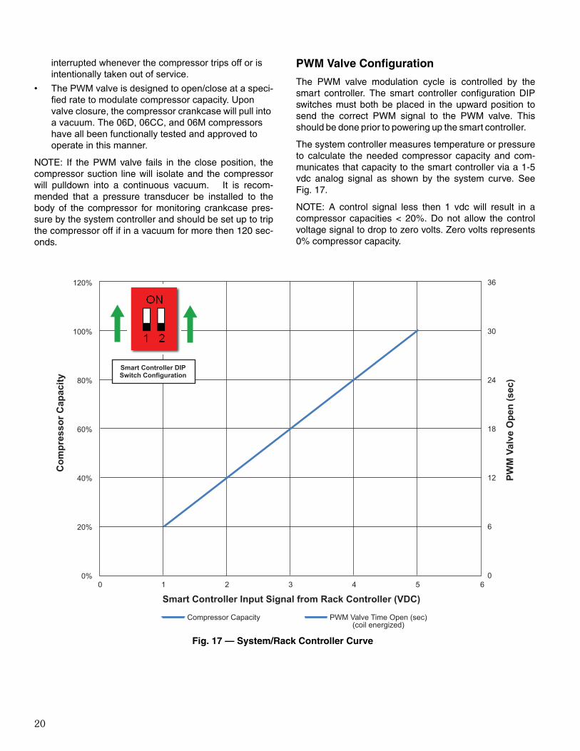
PWM Valve Configuration
The PWM valve modulation cycle is controlled by thesmart controller. The smart controller configuration DIPswitches must both be placed in the upward position tosend the correct PWM signal to the PWM valve. Thisshould be done prior to powering up the smart controller.
The system controller measures temperature or pressureto calculate the needed compressor capacity and com-municates that capacity to the smart controller via a 1-5vdc analog signal as shown by the system curve. SeeFig. 17.
NOTE: A control signal less then 1 vdc will result in acompressor capacities < 20%. Do not allow the controlvoltage signal to drop to zero volts. Zero volts represents0% compressor capacity.
120%
100%
80%
60%
40%
20%
0%
36
30
24
18
12
6
00 1 2 3 4 5 6
Com
pres
sor C
apac
ity
PWM
Val
ve O
pen
(sec
)
Smart Controller Input Signal from Rack Controller (VDC)
Smart Controller DIPSwitch Configuration
Compressor Capacity PWM Valve Time Open (sec)(coil energized)
Fig. 17 — System/Rack Controller Curve

21
Service Table
Use this service table to verify that the PWM valve ismodulating correctly per the applied voltage signal to thesmart controller.
SMART CONTROLLER
06D, 06CC, 06M COMPRESSOR CAPACITY
PWM VALVE
Demand Signal Input (vdc) Percentage Solenoid Coil Energized (sec)
1.0 20% 6
1.5 30% 9
2.0 40% 12
2.5 50% 15
3.0 60% 18
3.5 70% 21
4.0 80% 24
4.5 90% 27
5.0 100% 30
22
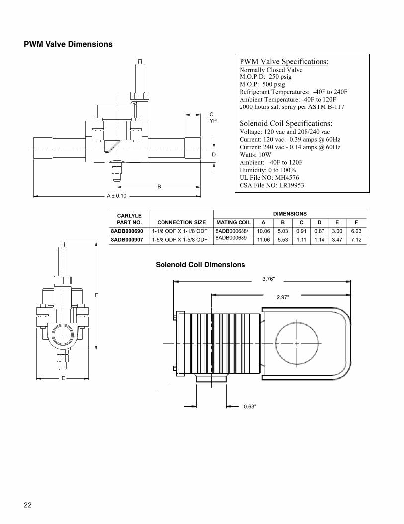
PWM Valve Dimensions
F
E
CTYP
D
B
A ± 0.10
PWM Valve Specifications: Normally Closed Valve M.O.P.D: 250 psig M.O.P: 500 psig Refrigerant Temperatures: -40F to 240F Ambient Temperature: -40F to 120F 2000 hours salt spray per ASTM B-117
Solenoid Coil Specifications: Voltage: 120 vac and 208/240 vac Current: 120 vac - 0.39 amps @ 60Hz Current: 240 vac - 0.14 amps @ 60Hz Watts: 10W Ambient: -40F to 120F Humidity: 0 to 100% UL File NO: MH4576 CSA File NO: LR19953
3.76"
2.97"
0.63"
Solenoid Coil Dimensions
CARLYLE PART NO. CONNECTION SIZE
DIMENSIONS
MATING COIL A B C D E F
8ADB000690 1-1/8 ODF X 1-1/8 ODF 8ADB000688/8ADB000689
10.06 5.03 0.91 0.87 3.00 6.23
8ADB000907 1-5/8 ODF X 1-5/8 ODF 11.06 5.53 1.11 1.14 3.47 7.12


CARLYLE COMPRESSOR DIVISION • © CARRIER CORPORATION 2014P.O. Box 4808 • Syracuse, New York 13221Phone 1-800-532-5031 • Fax 1-315-432-3274In U.S. and Puerto Rico: 1-800-GO-CARLYLE (1-800-462-2759)In Canada: 1-800-258-1123In Mexico: 001-800-GO-CARLYLE (001-800-462-2759) 001-800-GO-CARLYLE (001-800-462-2759)
Manufacturer reserves the right to discontinue, or change at any time, specifications or designs and prices without notice and without incurring obligations.
Lit. No. 574-078(5/15)