Embed Size (px)
Citation preview

Smart Solutions. Powerful Products.
SR-Series Manual
1
Drill Pipe Float Valves // 2012
Smart Solutions. Powerful Products.

TABLE OF CONTENTS
1. Actuator Configuration ........................................................... 2
2. Performance ........................................................................... 3
3. Specification ........................................................................... 4
4. Actuator Partial Configuration ................................................ 5
5. Manual Operation ................................................................... 6
6. Limit Switch Setting ................................................................ 7
7. Mechanical Stop Bolt Limit Setting .......................................... 8
8. Dimension .............................................................................. 9
9. Electrical Wiring .................................................................... 11
10. Wiring ................................................................................ 13
11. Maintenance ....................................................................... 14
12. Warranty Information ......................................................... 14
2
TABLE OF CONTENTS
1. Actuator Configuration ........................................................... 2
2. Performance ........................................................................... 3
3. Specification ........................................................................... 4
4. Actuator Partial Configuration ................................................ 5
5. Manual Operation ................................................................... 6
6. Limit Switch Setting ................................................................ 7
7. Mechanical Stop Bolt Limit Setting .......................................... 8
8. Dimension .............................................................................. 9
9. Electrical Wiring .................................................................... 11
10. Wiring ................................................................................ 13
11. Maintenance ....................................................................... 14
12. Warranty Information ......................................................... 14
Features
SealingStandard enclosure with O-ring sealing is wa-tertight to IEC IP67, NEMA 4, 4x. The actuator is available with an optional explosion proof enclosure as well as IP68, NEMA 6.
MotorThe squirrel caged induction motor is totally enclosed with a high stall torque and low inertia force to suit seating/unseating of valves. Integral thermal protection is included to prevent damage to the single and three phase motors.
WiringElectrical wiring control circuits are standardized and color coded for single and three phase actuators. Additional terminal contacts can be easily added as required for various options.
MountingMounting base configurations are standardized to ISO 5211 and ABZ valve standards. The drive bushing is removable for machining to valve stem dimensions. The actuator position on the valve can be selected for 4 positions by means of 4 bolt holes in the drive bushing.
HeaterA space heater inside the actuator helps to prevent condensation due to temperature and weather changes. Standard 20W heater helps keep all electrical components in the actuator dry.
Limit SwitchesThe limit switch is activated by means of a simple and yet reliable cam mechanism mounted and driven by the center column. The valve position can be accurately and easily set with the simple adjustable switch cam mechanism. The set position is permanent and is not affected by over-travel resulting from manual operation.
1. Actuator Configuration
Spring Body
Window
Worm Gear
Stop Bolt
Handwheel
Base
Planetary Gear
Motor

3
2. PerformanceType ABZ-E430SR ABZ-E860SR ABZ-E1730SR ABZ-E2600SR
Max Output Torque
In. lb. 430 860 1730 2600
Nm 50 100 200 300
Spring Return Time (90°) Sec 1
(Governor Optional: 2 ± 1 sec)1~2
(Governor STD)2 ± 1
(Governor STD)
Operating Time (90°)sec
(Open/Close)
110V 50hz 16/14 18/16 61/56 90/81
120V 60hz 14/12 16/14 51/46 72/68
220V50hz 16/14 20/19 62/57 89/82
60hz 13/12 17/15 51/47 75/68
380V50hz 17/15 21/19 62/57 87/82
60hz 15/13 19/16 52/47 74/68
440V50hz 17/15 21/19 62/57 86/82
60hz 15/13 17/16 52/47 73/67
DC24V 13/10 20/12 56/35 86/56
Motor (W)AC 60 90 90 90
DC 40 40 40 40
Duty (S2) Min 15 15 15 15
Rated Current (A)(Open/Close)
110V 50hz 1.75 / 1.68 2.4 / 2 2.8 / 2.43 2.3 / 1.8
120V 60hz 1.7 / 1 3 / 2.2 3.9 / 2.9 3.15 / 2.3
220V50hz 1 / 0.95 1.06 / 0.98 1.3 / 0.97 1.02 / 0.98
60hz 1.03 / 0.7 1.3 / 0.9 1.8 / 0.43 1.3 / 0.95
380V50hz 0.24 / 0.18 0.4 / 0.33 0.38 / 0.3 0.35 / 0.3
60hz 0.25 / 0.15 0.4 / 0.22 0.35 / 0.3 0.29 / 0.2
440V50hz 0.28 / 0.17 0.5 / 0.5 0.5 / 0.5 0.62 / 0.6
60hz 0.24 / 0.17 0.4 / 0.3 0.36 / 0.31 0.31 / 0.27
DC24V 6.3 / 1.9 8.6 / 1.65 9 / 1.8 7.6 / 1.8
Stall Current (A)
110V 50hz 3.72 4.0 4.78 4.7
120V 60hz 3.55 4.1 5 4.72
220V50hz 1.95 2.55 2.4 2.8
60hz 1.9 2.5 2.5 2.93
380V50hz 0.82 0.8 1.3 0.7
60hz 0.77 1.22 1.3 0.8
440V50hz 0.92 0.83 1.54 0.6
60hz 0.9 1 1.45 0.7
DC24V 15 13 15.7 13.5
Mounting BaseABZ
(ISO5211)3.25” (F07)
3.25”/ 5.0” (F07 / F10)
3.25”/ 5.0” (F10 / F12)
3.25”/ 5.0” F10 / F12)
Handwheel Turns 25 25 75 113
WeightLb
(Kg)
STD 57 (26) STD 77 (35) STD 112 (51) STD 137 (62)
EXP 68 (31) EXP 88 (40) EXP 112 (51) EXP 148 (67)
* Non-Standard (110V/50hz)
*
*
*

4
3. Specification
EnclosureStandard: NEMA 4, 4x Optional: Explosion Proof Ex d II B T4, IP67Optional: Watertight (IP68)
Ambient TemperatureStandard: -20ºC ~ 55ºC (-4°F ~ 131°F) Optional: -40°C ~ 55°C (-40°F ~ 131°F)Optional: -60°C ~ 55°C (-76°F ~ 131°F)
Power SupplyStandard: 120 VAC or 220 VAC 1-PhaseOptional: 380 VAC or 440 VAC 3-PhaseOptional: 24 VDC
Auxillary Limit Switch Open/Close Limit Switch (250VAC 15A)
GovernorStandard: ABZ-E1730SR & ABZ-E2600SROptional: ABZ-E430SR & ABZ-E860SR
Travel Angle 90º ± 5º
Indicator Continuous Position Indicator
Mechanical Stops External Adjustable Screws
Space Heater 20W
Conduit EntriesStandard: 3/4” NPT Optional: 3/4” PF Optional: M20
Lubrication Shell Gadus S2 V220 2
Materials Aluminium Alloy
Surface Treatment Anodizing
Coating Polyester (TGIC - Free)
5
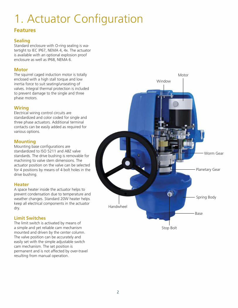
4. Actuator Partial Configuration
Wiring Connector Motor
Micro Switch (Limit)
ABZ-E430SR, ABZ-E860SRABZ-E1730SR, ABZ-E2600SR
:Option:StandardGovernor
Handwheel
Stop Bolt
Indicator
Spring Cover
Earth Earth
Spring Body

6
5-1
5. Manual OperationTurn the lever located on the side of the actuator toward the handwheel. The lever should LOCK in position. Turn the handwheel and the actuator output will rotate.
5-2 If the lever does not LOCK in the upright position, then turn the handwheel halfway and pull lever to the up-right position.
-Turn the handwheel clockwise for CLOSE
-Turn the handwheel counter clockwise for OPEN
Lever
7
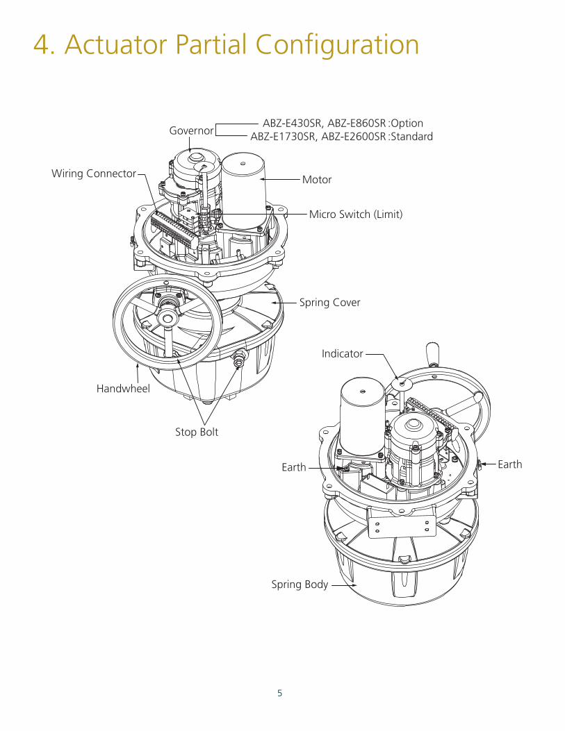
AOLS Dry Contact Open Limit Switch
ACLS Dry Contact Close Limit Switch
OLS Open Limit Switch
CLS Close Limit Switch
6. Limit Switch Setting6-1. Close/Open Switch Adjustment
6-1-1.Confirm that the power is off.Turn lever located on the side of the actuator to engage the manual override handwheel.Rotate the handwheel clockwise to fully close the actuator/valve.
6-1-2.Loosen the CLS and ACLS cam set screws as shown. Rotate cams in the closed/clockwise direction and engage the switch levers to trip the corresponding switch.
6-1-3.Firmly re-tightened the cam set screw.
6-1-4.To set the open limit switch, follow the same procedure as above except that the rotation will be counter-clockwise using the open limit switch cam.
AOLS
ACLS
OLS
CLS

8
7. Mechanical Stop Bolt Limit Setting
7-1
7-2
7-3
Turn the lever located on the side of the actuator toward the handwheel. The lever should LOCK in position. Turn the handwheel and the actuator output will rotate.
As shown below, turn the stop bolt into the body until contact is made between the limit stop and dash pot. After contact is made, then turn the limit stop back out one turn and lock it in place with the nut by tighten-ing the nut against the body.
To set the open limit stop, follow the above instructions except rotate the actuator in the counter-clockwise rotation.
Do not rotate factory set limit stop bolts more than 5 turns from set point. If the mechanical stops are improperly set, motor and gear damage may occur.After setting the limit stops, check for proper function by operating the actuator both manually and electrically. Confirm that the end of travel limit switches shut off power to the motor in both the open and closed positions, and that the motor is not stalled or in an over-torque condition.
In the event of a limit switch malfunction, the stop bolts will prevent the actuator from over traveling and causing damage to the valve. The stop bolts should be reset whenever any adjustment is made to the open and closed limit switches, this will protect the valve in the event of an electrical malfunction.
Stop Plate
View from top
Output Shaft
Stop BoltOpen (CCW) Adjustment
Spring Body
Stop BoltClose (CW) Adjustment
Nut
9
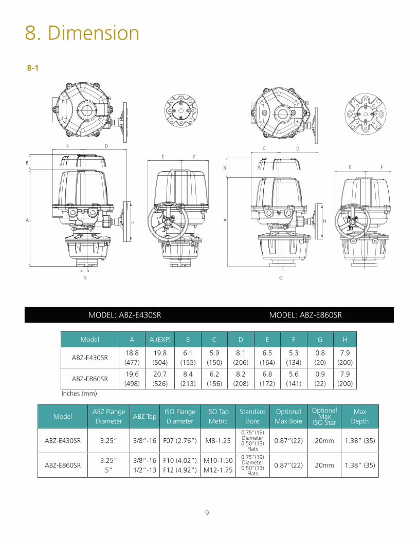
Model A A (EXP) B C D E F G H
ABZ-E430SR18.8 (477)
19.8 (504)
6.1 (155)
5.9 (150)
8.1 (206)
6.5 (164)
5.3 (134)
0.8 (20)
7.9 (200)
ABZ-E860SR19.6 (498)
20.7 (526)
8.4 (213)
6.2 (156)
8.2 (208)
6.8 (172)
5.6 (141)
0.9 (22)
7.9 (200)
ModelABZ FlangeDiameter
ABZ TapISO Flange Diameter
ISO Tap Metric
StandardBore
OptionalMax Bore
OptionalMax
ISO Star
MaxDepth
ABZ-E430SR 3.25” 3/8”-16 F07 (2.76”) M8-1.250.75”(19) Diameter0.50”(13)
Flats0.87”(22) 20mm 1.38” (35)
ABZ-E860SR3.25”
5”3/8”-16 1/2”-13
F10 (4.02”) F12 (4.92”)
M10-1.50 M12-1.75
0.75”(19) Diameter0.50”(13)
Flats0.87”(22) 20mm 1.38” (35)
8. Dimension
8-1
MODEL: ABZ-E860SRMODEL: ABZ-E430SR
Inches (mm)
A A
BB
CCD
D
H H
E
E
F
F
G G
10
8-2
Model A A (EXP) B C D E F G H
ABZ-E1730SR24.2 (615)
24.2 (615)
8.4 (213)
6.2 (156)
8.5 (217)
6.8 (173)
5.6 (141)
0.9 (22)
7.9 (200)
ABZ-E2600SR25.9 (659)
27.1 (687)
8.4 (213)
6.2 (156)
8.4 (214)
6.8 (173)
5.6 (141)
0.9 (22)
7.9 (200)
ModelABZ FlangeDiameter
ABZ TapISO FlangeDiameter
ISO Tap Metric
Standard Bore
OptionalMax Bore
OptionalMax
ISO Star
MaxDepth
ABZ-E1730SR 5” 1/2”-13F10 (4.02”) F12 (4.92”)
M10-1.50 M12-1.75
1.125”(28.6) Diameter0.25”(6)
Key1.26”(32) 26mm 1.65” (42)
ABZ-E2600SR 5” 1/2”-13F10 (4.02”) F12 (4.92”)
M10-1.50 M12-1.75
1.125”(28.6) Diameter0.25”(6)
Key1.26”(32) 26mm 1.65” (42)
MODEL: ABZ-E2600SRMODEL: ABZ-E1730SR
Inches (mm)
A
A
B
BC
C
D
D
H
H
EE
FF
G G

11
9. Electrical Wiring
Cable
Flathead Screw Driver
WAGO Terminal
Push and Set
Wire Preparation
AWG 28 –14 8~9mm
0.08~2.5mm
9-1
9-2
9-3
9-4
9-5
9-7
9-6
9-8
Separate the cover of the actuator by loosening the four cover bolts.
Confirm that the wiring diagram located in the actuator and Wiring No. on the name plate match with each other.
Confirm that the main power and power supply described on the name plate of the actuator match with each other.
SR Series uses a WAGO brand terminal strip to allow easy wiring and to protect against vibration.
Insert a small flathead screwdriver as shown to open the terminal point, then insert the wire.
Be sure to wire and energize the heater that is provided.
Be sure to properly ground the actuator wiring to the grounding terminals provided on the inside and outside of the actuator body.
Each actuator must be powered by their own individual relays to prevent voltage feedback and actuator damage.
Inside & Outside earth terminal

12
9-9
9-10
9-11
9-12
With a 3 Phase (380, 440V) powered actuator, care must be taken to confirm the proper motor rotation when the power and signal are applied. If the actuator rotates in the reverse direction than what is expected, the limit switches will not function correctly and a mis-wire has occured. Corrective action needs to be taken.
After the wiring is completed in the actuator, use wire ties to clean up the actuator and group wires together, and be certain that the wires are secured away from any moving parts, remove any loose debris.
Main power must only be applied when the top cover is re-installed on the actuator body.If the main power is on while wiring the actuator stop work immediately and turn the power off. Only then is it safe to proceed.
When all the work is completed, replace the top cover and secure it using the four cover screws.
Apply the power and do a final check to confirm proper operation.
9-9-1With power disconnected, manually operate the actuator to a mid position.
9-9-2Apply power / signal to rotate the actuator open or closed and confirm the rotation is correct.
9-9-3If the rotation is incorrect, then shut off the actuator and rewire two of the three wires as shown.
Terminal BlockTerminal Block
In the case of a reverse phase
13
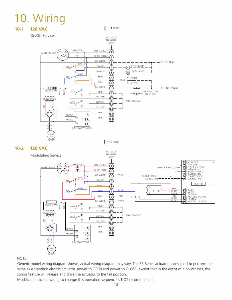
10. Wiring120 VAC
120 VAC
10-1
10-2
On/Off Service
Modulating Service
NOTE:Generic model wiring diagram shown, actual wiring diagram may vary. The SR-Series actuator is designed to perform the same as a standard electric actuator, power to OPEN and power to CLOSE, except that in the event of a power loss, the spring feature will release and drive the actuator to the fail position. Modification to the wiring to change this operation sequence is NOT recommended.
1
2
3
4
5
6
7
8
9
10
11
12
13
14
1
2
3
4
5
6
7
8
9
10
11
12
13
14
(L2) NEUTRAL
CLOSE LAMPC
OOPEN LAMP
OPEN
CLOSESTOP
(L1) LINE (120vac)
SPRING ACTIONFAIL CLOSE
AUX. CONTACT
AUX. CONTACT
WHITE
EARTH
BLUE
RED
RED
RED
WHITE
WHITE
BLACK
BLUEWHITE
(L1) LINE (120vac)(L2) NEUTRAL
DHC-100
(SELECT 1 INPUT) (+)
8 +15V OUT 7 +5V OUT6 1-5, 0-5, 0-10 (+)5 4-20mA (+)4 SIGNAL GND. (–)3 EARTH / GRN2 (L1) HOT / LINE1 (L2) NEUTRAL
6 +2.5V5 WIPER4 GROUND 3 MOTOR 2 OUTPUT2 NEUTRAL1 MOTOR 1 OUTPUT
(–)
J-2
J-13
21
EARTH
RED
BLUE
CAPACITORWHITE / BLACK
MOTOR
TP
WHITE / RED
ACTUATOR TERMINAL
STRIP
E.M READY STATUSAUTO
MANU
AC1
AC2
COMBLACK
WHITE
DC90V
WHITE / BLUE
G/F WHITE
BLACK
ORANGE
BLUE
RED
G/F WHITE
HEATER (20W)
BLA
CK
BLA
CK
RED
RED
BLU
E +
BLU
E –
ACLS
CLS
1
1
1
2
2
2
3
3
3
2
31
AOLS
OLS
TRANSFORMER
BRAKE15W
PINK
YELLOW
BROWN
YELLOW
PINK
PINK
RED
BLUE
CAPACITORWHITE / BLACK
MOTOR
TP
WHITE / RED
ACTUATOR TERMINAL
STRIP
E.M READY STATUSAUTO
MANU
AC1
AC2
COMBLACK
WHITE
DC90V
WHITE / BLUE
G/F WHITE
BLACK
ORANGE
BLUE
RED
G/F WHITE
HEATER (20W)
BLA
CK
BLA
CK
RED
RED
BLU
E +
BLU
E –
ACLS
CLS
1
1
1
2
2
2
3
3
3
2
31
AOLS
OLS
TRANSFORMER
BRAKE15W
PINK
YELLOW
BROWN
YELLOW
PINK
PINK
14
11. Maintenance
12. Warranty Information
11-1
11-2
Lubrication
Regular Check Up
12-1
12-2
12-3
12-4
12-5
12-6
12-7
12-8
Under normal conditions, no additional grease needs to be added to the actuator. However if the ambient temperature is greater than 40ºC and if the humidity is less than 15%, periodic re-greasing is recommended.The recommended grease used in the SR Series actuator is Shell Gadus S2 V220 2.
It is recommended that the actuator be cycled every two weeks after purchase. To minimize the effects of condensation in the actuator it is recommended that the conduit entries are sealed at the actuator and that the heater is energized.
Failure or damage caused by misuse or abuse.
Failure or damage caused by unauthorized modifications or repairs done to the actuator.
Failure caused by the unauthorized modification / change of the wiring.
Failure caused by a reverse phase mis-wire when using three phase power.
Failure caused by water leakage due to the improper sealing of the actuator conduit entries or by failure to install the cover properly.
Failure caused by improperly set limit switches.
Failure caused by fire, flood damage, or other “acts of God.”
Failure occuring 1 year after the shipment date.

ABZ Valve & Controls113 W. MAIN STREETP.O. Box 157MADISON, KS 66860620-437-2440855-803-6786www.f-e-t.com
3/2015
OUR CORE VALUES
No one gets hurt: The safety of our employees and customers is
our first priority coupled with a healthy respect for the environment.
Integrity: In everything we do, in every interaction, both internally and exter-
nally, we strive to operate with the utmost integrity and mutual respect.
Customer focused: Our products enhance our customer’s
performance and we listen to their needs and work with them to
solve their challenges.
Good place to work: We are committed to creating a workplace that fosters
innovation, teamwork and pride. Every team member is integral to our success
and is treated equally and fairly.
Our goal is to become the leading provider of mission critical oilfield products and related services in terms of customer satisfaction, safety and financial performance.
Our experienced management team and employees are dedicated to solving our customers’ problems. We invest in long term relationships and cooperate on product development with our clients, we consider them our partners.