Embed Size (px)
Citation preview

SMART SIGNALS FINAL DESIGN REPORT
Team: Smart Signals
By: Adam Hieb, Dan Miller, Bryan Humphrey, Gabriel DeRuwe, and Kyle Schiepan
April 16, 2007
Gabriel DeRuwe Bryan Humphrey
Daniel Miller Kyle Schiepan
Adam Hieb

Executive Summary
The goal of this project was to implement a system that improves the existing traffic
signal technology in a way that benefits both pedestrians and traffic engineers. This
system allows for two-way communication between the traffic controller and the
components of this system, simplifies the wiring to each of the system devices, and
allows for confirmation when a pedestrian presses the pedestrian button. It also includes a
wireless pedestrian button for disabled pedestrians who might have trouble physically
accessing the regular button. This system also includes a countdown timer for aiding
pedestrians crossing the intersection, a two-way communication bridge between the
traffic controller and the signals, and a system monitor that records any changes to human
observable events generated by the system, i.e. the traffic lights changing. This design
report outlines the processes we used to design the system, and how to operate this
system.

Table of Contents
Background ................................................................................................... 1
Problem Definition ........................................................................................ 2
Concepts Considered ..................................................................................... 4
Concepts Selected .......................................................................................... 7
Product Description ...................................................................................... 10
Product Evaluation ........................................................................................ 13
Economic Analysis ....................................................................................... 20
Conclusions and Recommendations ............................................................. 24
Appendix A.................................................................................................... 27
Appendix B .................................................................................................... 30
Appendix C .................................................................................................... 50
Appendix D.................................................................................................... 58
Appendix E .................................................................................................... 68
Appendix F..................................................................................................... 72
Appendix G.................................................................................................... 77

Background
Pedestrian crosswalks are designed to allow safe passage of pedestrians at road
intersections. Due to the special needs of some pedestrians, many crosswalks are unsafe
to cross. The technology is there to make these crosswalks safe for all pedestrians, it just
requires somebody to design and build it. For this, Dr. Richard Wall proposed a three
year project for designing, testing, and building of a new system, compliant with current
traffic intersection standards, that includes features to increase the safety of non-fully
able-bodied pedestrians. Last years project, designed and built by team Lite Bright,
introduced a countdown timer that updates directly off of the traffic controller for
increased accuracy. This year’s project is based off of the work done by the Lite Bright
team, while adding extra features for pedestrians.

Problem Definition
Countdown Timer
The goal for the countdown timer is to create a countdown timer pedestrian signal that
accurately displays the amount of time left for the pedestrian to cross the street. This
timer should adjust for any outside interruption (such as pre-emption from an ambulance)
and must allow for feedback, or data sent back to the traffic controller. The timer also
needs to conform to the Manual on Uniform Traffic Control Devices (MUTCD) which is
a specification book on how a traffic signal must look, how it must operate, location of
the signals, etc.
In order to most accurately display the countdown signal in all possible cases, a
microcontroller will need to be implemented in place of the I/O expander and load
switches that currently operate the pedestrian signal. Doing so allows also allows for
feedback, which is desirable when implementing this design on a large scale. The
problem will have been solved when a working pedestrian signal operates identical to
current operation, with a microcontroller in place. Future modifications down the road
should then be as simple as writing new code for the microcontroller and plugging it
straight in. Another test to make sure the problem is solved is to force a pre-emption and
check for proper operation in the next phase. As proved by Lite Bright last year, the
current pedestrian signal will display the wrong value for the next phase, where our
design should show the correct value.
Local Pedestrian Button
One of the current goals of the project is to create a smart pedestrian button. The button
must be capable of taking input from the pedestrian, providing feedback to the pedestrian,
and communicate on a power line over Ethernet network. This device must conform to
all of the current standards of traffic signals.

Network
The goal is to create a smart intersection that can respond to the needs of any pedestrian
that decides to use it. Keeping that in mind communication between the parts is a must.
Lite Bright used Ethernet over power for communication between the more distant
devices, particularly the countdown timer, walk/don’t walk signal, and the pedestrian
button. Unfortunately problems cropped up in the design from last semester, some
seeming to stem from a communication error over the Ethernet over Power. Beyond that,
Lite Bright wanted to show that their Plug-n-Play (PnP) master was a separate device
from their translator so they put these two pieces in two different Rabbit Processors and
they communicate via serial cable. Having two physically separate boards is infeasible
for actually deploying this system, so they will be combined into a single board
communicating via master-slave protocols. During the course of developing this master-
slave communication it was decided to change the network protocol from IEEE 1451 to
the standard used for communication in the Traffic signal environment, NTCIP. The
change to this communication standard instituted a massive change to the network
topology. Instead of needing one device to poll the traffic controller and then another
device to send that information to the network, only one device is needed to poll the
traffic controller and rebroadcast that information to the network. This may seem like an
extra step, but it was discovered that the devices used for communicating on the network
were unable to be put in the promiscuous mode which is necessary to view network
traffic not destined for that device that is not broadcast traffic. Due to this hurdle, the
rebroadcast is necessary to allow the nodes to update their view of the intersection data.
Wireless Pedestrian Button
Currently, the intersection is not able to identify special needs users. If a blind person
needs to use the intersection, they must find the pole, press the button, then re-orient
themselves before they can walk. By providing a remote pedestrian button, the user can
maintain heading. Also, the intersection can acknowledge the presence of a special needs

user. Chirps and other forms of feedback can only be enabled for blind people; time can
be extended for people in wheel chairs, etc.
System Monitor
Finally, the timing and response of the new traffic controller system will need to be
verified, so that proper system functionality is shown to be taking place. For this, a
system will be developed that will monitor the inputs and outputs of the system and time-
stamp every relevant event that took place and record that information for analysis. The
purpose of this system monitor is to make sure that the signals being generated by the
system fall within a timing variance that is not noticeable by human observation.
Concepts Considered
Countdown Timer
The countdown timer part of the project did not require quite as many concepts to
consider, because of the necessity to conform to MUTCD standards. These standards rule
out using Lite Bright’s countdown timer and pedestrian signal, because the requirement is
for one head, and Lite Bright’s had two. We realized that we were left with two options:
create our own MUTCD-compliant pedestrian head with both the pedestrian graphic on
one side and a timer on the other, or take an already existing pedestrian head with a
countdown timer already built in, remove the controller and wire in our own
microcontroller. The MUTCD states that in order to be visible across the intersection, the
signals and the timer both have to be at least 9 inches high, so both options would look
very similar. The MUTCD also states that the signal has to follow a strict order of
functions: first, it must display the walk signal for a minimum of 10 seconds, then it must
flash the ”don’t walk” signal for the remainder of the cycle. This means that both options
for our pedestrian head would have to function nearly identically.

Local Pedestrian Button
There are only a few concepts considered for the pedestrian button. One of the concepts
considered was the type of display for the pedestrian feedback. Some of the options
included seven segment displays, liquid crystal displays and light emission diodes. One
of the other concepts considered was replacing the mechanical button with a non
mechanical button such as a capacitive sensor like those found in touch lamps. The
feasibility of the senor was not great enough to replace the mechanical button. Another
considered concept was to include audio capabilities for visually impaired pedestrians.
One of the main concepts of the pedestrian button is that it will conform to all of the
current regulations and restrictions involving traffic signals.
Network
The network protocol was changed from IEEE 1451 to NTCIP, which allows for some
changes in the network topology. Due to the change to NTCIP it simplified the network,
needing only three distinctive types of devices to function. The first device, the
commander, polls specific data structures on the traffic controller for data needed for the
nodes. The nodes are the second type of device; they are passive listening devices that
gather the data that the commander polls. The last device is the Power line-carrier
Ethernet that bridges all the nodes on the network together via the power system. For the
network topology, two possibilities were considered, one using a passive approach for the
nodes, and the other was a less-passive approach. The first approach would involve the
nodes being in promiscuous mode so that the response from the traffic controller to the
commander would be seen by all nodes and the data necessary obtained from that
response. The second approach has the commander resending, via broadcast, the
response received so that the nodes could see the response. This second approach has the
disadvantage of about triple the network overhead of the first approach, but as discovered
the Rabbit microcontrollers have no capability to ‘sniff’ network traffic.

Wireless Pedestrian Button
There are many concepts that have been considered for the remote pedestrian button.
Some ideas include audio feedback to the user, tactile feedback, GPS for location and
heading, magnetic compassing for heading, and RFID for location and failsafe mode.
Audio feedback can be included in the intersection to provide the user with information
such as the number for lanes that need to be crossed (useful for blind pedestrians). Audio
feedback can also be used on the handheld device. The remote button can chirp loudly
when the pedestrian is on course, and chirp quietly when the pedestrian is drifting off
course. Another option is to use headphones. Chirps in both ears can be heard when the
user is on course, and chirps in the left ear when the user needs to change heading to the
left, and chirps in the right ear when the user needs to change heading to the right. Tactile
feedback can be used to inform the user of special events. For example, a short vibration
can be used for acknowledgement, two short vibrations to inform the user to walk, etc.
GPS can be used to locate the user’s position and heading, thus allowing us to trigger the
correct crosswalk for the user. Another method of discovering the users heading is
magnetic compass sensing. Magnetic compass sensing measures the earth magnetic fields
with regards to three axis and measures tilt and roll. Using the given data, a compass
heading can be derived. Finally, RFID is considered. RFID has a short range, thus
allowing us to identify their presence at the intersection. Also, RFID does not require a
battery. If the remote pedestrian button fails, the intersection can acknowledge their
presence and warn the user that the unit needs repair.

System Monitor
The implementation of the system monitor is pretty straight-forward as the needs that it
satisfy are very specific to the project as a whole. The general idea behind the system
monitor is to monitor events generated by this system, including signals generated by the
new system being developed as well as signals coming from the traffic controller to
control events that were not changed, such as the traffic lights themselves. The concepts
behind getting the signals from both the new and old systems were pretty much the only
ones considered as there weren’t many different methods to implement the signal
conversion without affecting the watched system.
Concepts Selected
Countdown Timer
When it came time for selecting the concept, we felt that using an industry standard
countdown timer and pedestrian signal, removing the controller, and putting a
microcontroller of our choice inside was the most practical decision. This ensures
MUTCD compliance, provided that we make it operate identically to how it would
operate with the traffic controller, maintains a sense of pedestrian familiarity, and
eliminates time-consuming designing and fabrication steps.
The microcontroller that will control the signal will be a Rabbit 3000, again, after
minimal alternative consideration. The Rabbit provides all the features we need for
controlling the signal, including easy integration for the remote pedestrian button
receiver, is easier and more familiar to us to implement and program for, and allows for
future expansion if more components are desired down the line. Wiring in the Xbee radio
for the remote pedestrian button is also easy with the Rabbit, as we have already shown
with our remote button prototype.
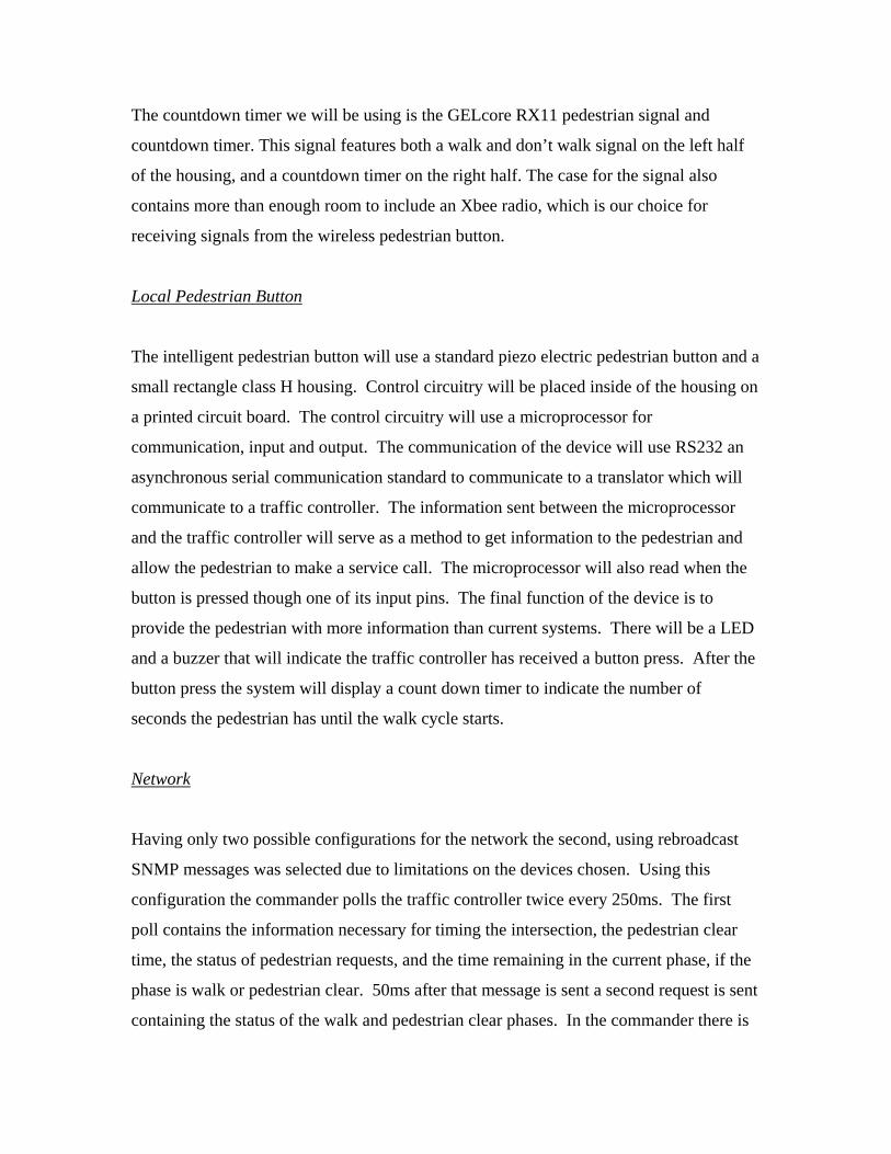
The countdown timer we will be using is the GELcore RX11 pedestrian signal and
countdown timer. This signal features both a walk and don’t walk signal on the left half
of the housing, and a countdown timer on the right half. The case for the signal also
contains more than enough room to include an Xbee radio, which is our choice for
receiving signals from the wireless pedestrian button.
Local Pedestrian Button
The intelligent pedestrian button will use a standard piezo electric pedestrian button and a
small rectangle class H housing. Control circuitry will be placed inside of the housing on
a printed circuit board. The control circuitry will use a microprocessor for
communication, input and output. The communication of the device will use RS232 an
asynchronous serial communication standard to communicate to a translator which will
communicate to a traffic controller. The information sent between the microprocessor
and the traffic controller will serve as a method to get information to the pedestrian and
allow the pedestrian to make a service call. The microprocessor will also read when the
button is pressed though one of its input pins. The final function of the device is to
provide the pedestrian with more information than current systems. There will be a LED
and a buzzer that will indicate the traffic controller has received a button press. After the
button press the system will display a count down timer to indicate the number of
seconds the pedestrian has until the walk cycle starts.
Network
Having only two possible configurations for the network the second, using rebroadcast
SNMP messages was selected due to limitations on the devices chosen. Using this
configuration the commander polls the traffic controller twice every 250ms. The first
poll contains the information necessary for timing the intersection, the pedestrian clear
time, the status of pedestrian requests, and the time remaining in the current phase, if the
phase is walk or pedestrian clear. 50ms after that message is sent a second request is sent
containing the status of the walk and pedestrian clear phases. In the commander there is

a handler function that immediately upon receipt of a message from the traffic controller
resends the received packet with a broadcast address so anything on the local network
hears this message. This resent message is received by the nodes and parsed for the
particular data above as it pertains to the state of their watched phase.
Wireless Pedestrian Button
Audio feedback, tactile feedback, GPS, magnetic compassing, and RFID were considered
for the remote pedestrian button. Audio feedback and magnetic compassing were
selected. Using audio feedback on the remote pedestrian button, we can use chirps to
acknowledge the users request and warn the user that their unit battery may be low.
Magnetic compassing provides us with a low power method of discovering the users
heading. Magnetic compassing is preferred over GPS because GPS requires a large
amount of size, power, and time for boot-up (searching for satellites, cannot find enough
satellites, etc).
System Monitor
For the system monitor, optical sensors were chosen to read the information about the
traffic signal from the load switches. This will have the effect of reading the signal from
the line while minimizing the effects from the monitor on the system. Maxstream radios
will be used to communicate with the pedestrian nodes. A master/slave system will be
implemented with the radios; a RABBIT microcontroller will request information to be
sent from a particular pedestrian node and the system will send the proper status
information from the requested node at that time. This microcontroller will collect
information from the optical sensors and the Maxstream radios and output time stamped
information to a PC in a CSV (Comma Separated Value) format.

Product Description
Countdown Timer
The GELcore RX-11 pedestrian signal is the display we are using in our design, although
we are just using the signal boards and throwing out the onboard controller. This signal
breaks apart the display into two different boards. On the left are the “walk” and “don’t
walk” symbols, in Lunar White and Portland Orange, respectively, with their LED arrays
conveniently intertwined on the board. These symbols are both wired up in a series-
parallel combination for two reasons: voltage requirements and potential for burned out
LEDs. On the right board is the countdown timer, which is a seven-segment display
implemented with Portland Orange LEDs. The segments contain either 10 or 15 LEDs
each, depending on the physical size of the segment, wired up in series-parallel
configurations with 5 LEDs in each branch. With 1.75 volts being the forward voltage
drop across the LED, the total voltage drop for each segment is 8.75 volts. Desired
current for each segment is 35 milliamps, regardless of whether 10 or 15 LEDs are used.
The voltage requirement for the “don’t walk” symbol is 54 VDC, and the “walk” symbol
requires 39 VDC. If the symbols were wired up in series, the voltage requirement would
easily approach 200 volts. With the series-parallel combination, the current draw is a bit
higher, at 85 milliamps for both symbols, but the voltage requirement has been dropped
dramatically. Also, with the series-parallel combination, if a segment of LEDs burns out,
the rest of the signal stays lit. A series combination with a burned-out has the potential of
failing open circuit, and therefore shutting off the entire symbol.
The countdown timer uses a single pin for power, and LED segments are turned on by
applying ground to specific pins. In order to use the timer in this method, we apply 12
volts at the power pin. We then wire the output through a 91-ohm resistor to drop the
remaining 3.25 volts and to limit the current at 35 milliamps. An N-channel MOSFET is
then wired in series, with the drain connected to the resistor and the source grounded. The

gate is tied to a single output pin on the Rabbit. When the Rabbit sets the output to a ‘1’,
the MOSFET is turned on, and the circuit is completed, lighting up the LED segment.
When the Rabbit sets the output to a ‘0’, the MOSFET is turned off, creating an open
circuit, which turns off the LED segment.
The Rabbit inside the pedestrian signal will receive its data from the system using
Ethernet over Power Line technology, as shown in Lite Bright’s countdown timer system
last year. Each pedestrian signal will therefore be added to the system as a new node in
the Plug and Play system, and will be able to be remotely configured using the
configuration tool written by Lite Bright.
Local Pedestrian Button
The pedestrian button will use RS232 communication. All information from the system
will be received and sent through the communication lines. The PSoC will control all
functions inside of the pedestrian button housing. The PSoC will update an LED seven
segment display to display the time to walk when a pedestrian button is pressed. When a
button is pressed the PSoC will also give an audible and a visual display when the
pedestrian button presses the button. The display will be an LED which is built into the
pedestrian button and the audible sound will be a buzzer that is also part of the
manufactured button.
Network
The move from IEEE 1451 to NTCIP simplified the network in such that only one Rabbit
3000-series microprocessor is necessary to poll the traffic controller for the state of the
intersection; this device is called the commander. The commander polls the traffic
controller for five specific Management Information Blocks (MIBs) contained in two
static SNMP messages (breakdown of the byte structure of these SNMP messages in
Appendix X). It would have been easier for the reply to these polls to be read by the
countdown timers themselves (hereafter, nodes), but due to the lack of a promiscuous

mode on the Rabbit microprocessors this data is instead rebroadcast by the commander
immediately upon receipt. The nodes parse the rebroadcast messages for the data
contained within and update the information for their particular phase that they are
watching which is hard-coded into each node during programming.
Wireless Pedestrian Button
The remote pedestrian button has 3 major components: HMC1055 magnetic compassing
kit, Xbee radio, and a PIC microprocessor. The PIC microprocessor will use the
HMC1055 chips to derive compass heading. The HMC1055 chips use analog voltages
and PWM to report the data necessary to calculate a heading. After the PIC calculates the
compass heading, the Xbee radio will be used to transmit the message to the intersection.
The message will include compass heading and user class data. User class identifies the
type of user as temporarily able bodied, blind, wheel chair, etc. All of these devices will
operate off of a common 3.6V battery pack consisting of 3 rechargeable NiMH batteries.
Because everything operates at this voltage, there is no need for a voltage regulator.
System Monitor
The system monitor will read the voltage coming off of the load switches in the traffic
controller cabinet to the signal heads using optical sensors and the information from
optical sensors will be fed into a RABBIT microcontroller via I/O expander chips. Also,
the microcontroller will interface with the pedestrian nodes via Maxstream radio
communication and collect status information about the pedestrian signals being
generated. The microcontroller will output the time stamped information in a CSV format
via a serial connection to a data logging PC every one-hundred milliseconds. The data
logging PC will write the CSV information coming from the microcontroller to files to be
imported into Excel.
Product Evaluation
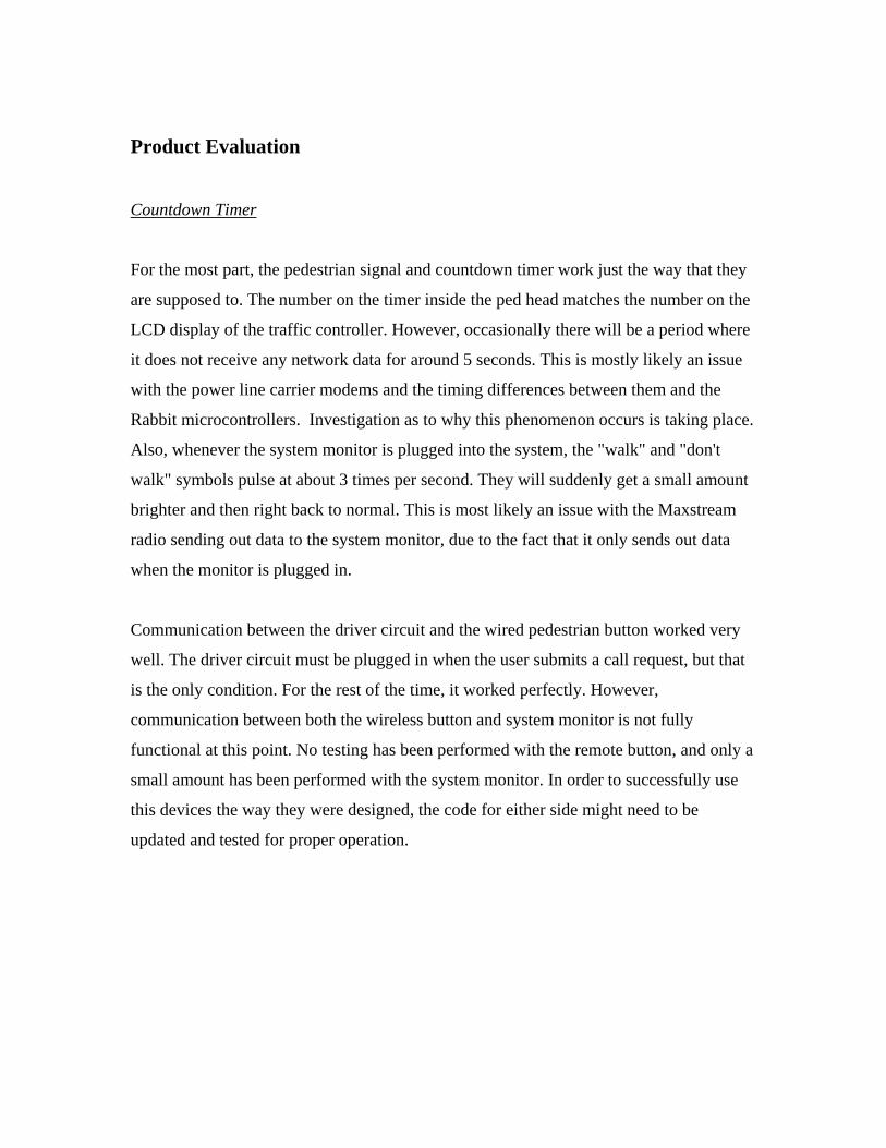
Countdown Timer
For the most part, the pedestrian signal and countdown timer work just the way that they
are supposed to. The number on the timer inside the ped head matches the number on the
LCD display of the traffic controller. However, occasionally there will be a period where
it does not receive any network data for around 5 seconds. This is mostly likely an issue
with the power line carrier modems and the timing differences between them and the
Rabbit microcontrollers. Investigation as to why this phenomenon occurs is taking place.
Also, whenever the system monitor is plugged into the system, the "walk" and "don't
walk" symbols pulse at about 3 times per second. They will suddenly get a small amount
brighter and then right back to normal. This is most likely an issue with the Maxstream
radio sending out data to the system monitor, due to the fact that it only sends out data
when the monitor is plugged in.
Communication between the driver circuit and the wired pedestrian button worked very
well. The driver circuit must be plugged in when the user submits a call request, but that
is the only condition. For the rest of the time, it worked perfectly. However,
communication between both the wireless button and system monitor is not fully
functional at this point. No testing has been performed with the remote button, and only a
small amount has been performed with the system monitor. In order to successfully use
this devices the way they were designed, the code for either side might need to be
updated and tested for proper operation.
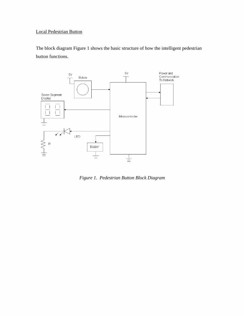
Local Pedestrian Button
The block diagram Figure 1 shows the basic structure of how the intelligent pedestrian
button functions.
Figure 1. Pedestrian Button Block Diagram

The control circuit is shown in Figure 2. This schematic is the basis for the project.
ORCAD, the software used to draft the schematic, was used to generate the bill of
materials and to create the net list for the layout of printed circuit board. This is the final
circuit diagram for the working system.
Figure 2. Schematic
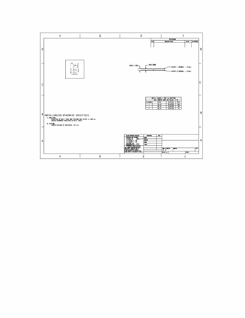
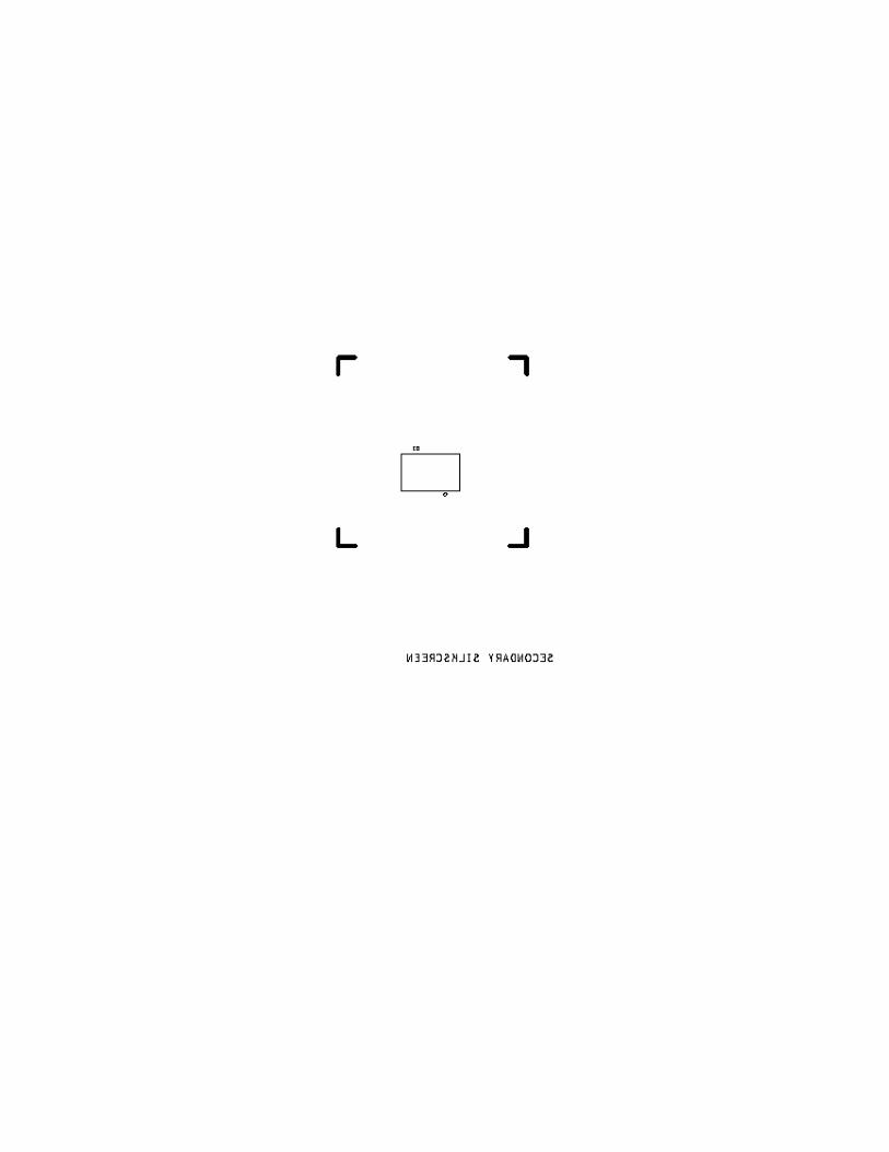
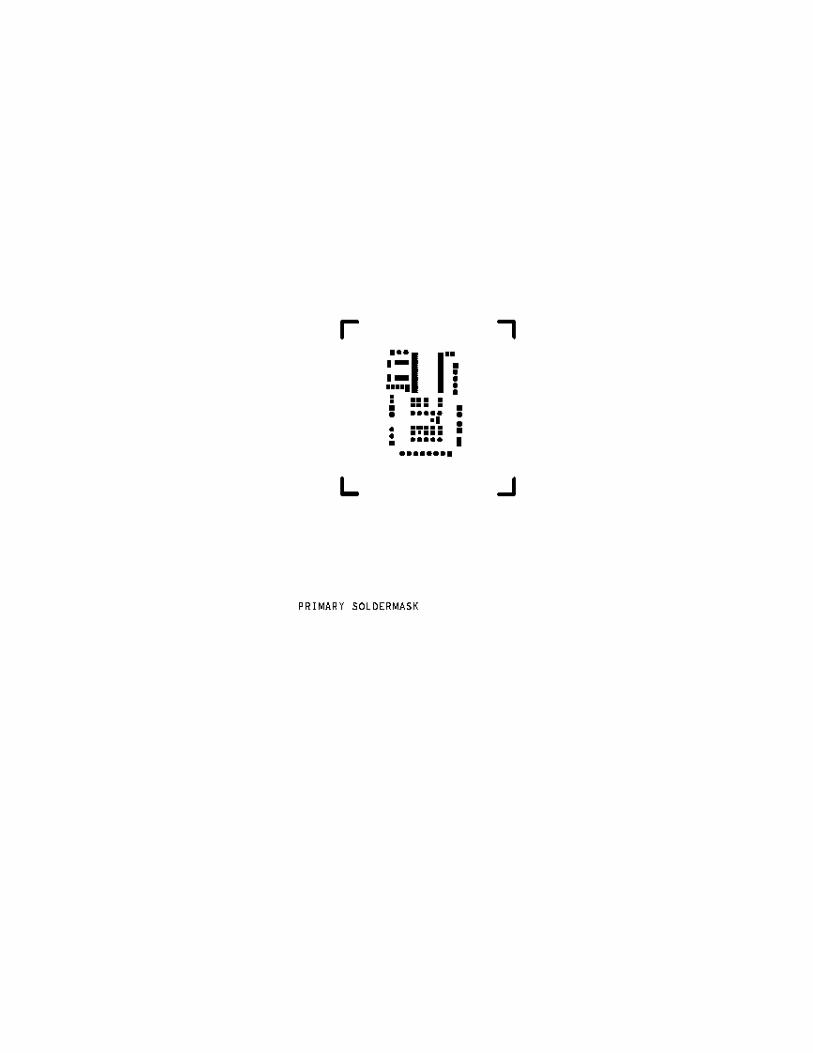
The circuit board design layers are included in Appendix B2 of the report. All layers of
the board are included that was fabricated. These layers include top copper, bottom
copper, primary silkscreen, secondary silkscreen, primary solder mask, secondary solder
mask, and the primary and secondary assembly. All components listed in Table are
placed on the board according to the reference designator associated with the part listed
in Appendix C, Complete Bill of Materials.xls, corresponds to where the part is installed

on the printed circuit board. The button, buzzer, and LED attach to the printed circuit
board according to the schematic description.
There were three incorrect connections on the printed circuit board fabricated. Appendix
B3 contains a new recommended layout for the working board. The three changes made
to make design work correctly include J2 pin 5 was connected to U1 pin 4 and was
reconnected to U1 pin 25. J2 pin 4 was connected to U1 pin 44 and was reconnected to
U1 pin 23. J1 pin 1 was connected to U1 pin 25 and was reconnected to U1 pin 31.
All of the electrical control components are listed in Appendix C including reference
designators to indicate placement on printed circuit board and also references to
schematic components.
The board connects to the count down timer board using the labeled pins on the board.
VCC and ground on J4 connect to JP2 VCC and ground respectively on the countdown
timer board. Second the R1in on J7 connects to T1out JP2 on the count down timer
board and T1out on J7 connects to R1in on JP2 on count down timer board. These
connections are made using a keyed Molex connector and 4 wires. This is shown in
Figure 3 below.
Figure 3. Connection Diagram

All of the components are place inside of the small rectangle class H housing and secured
using screws provided with the housing. The button is secured in the standard location.
The printed circuit board is placed in the opening at the bottom of the housing
The device operates using a C program. The code for the C program is included in the
final project compact disc. The program was written in PSoC designer and programmed
using PSoC programmer. The files for the project will be included on the project
compact disc.
Network
The original design called for a IEEE 1451 compliant network on the node-end and an
NTCIP compliant network on the traffic controller end. As the project progressed there
was much friction in gaining acceptance for the IEEE 1451 standard since NTCIP was
the accepted standard for the traffic controller industry. Due to this friction the network
was changed to entirely NTCIP-based such that all messaging would be taken care of by
SNMP. This has actually increased response on the network. There are some errors that
have been creeping in, specifically it has been seen at times where the countdown timer
will not update every second or sometimes even for as long as 6 seconds. During these
times it was seen that the traffic controller stopped responding to the get requests sent by
the commander, it is not known why at this point testing will need to be done.
Other issues include this system is only built for a 2-phase intersection and at this time
has not been tested with larger amounts of phases. Theoretically the intersection should
work assuming the nodes are updated for the intersections.
Wireless Pedestrian Button
The wireless pedestrian button was not successful due to the 200X OP AMP multiplier
circuit. A smaller error multiplied by 200 generated a large error. However, a proof of
concept design consisting of a factory built digital compass successfully reported user
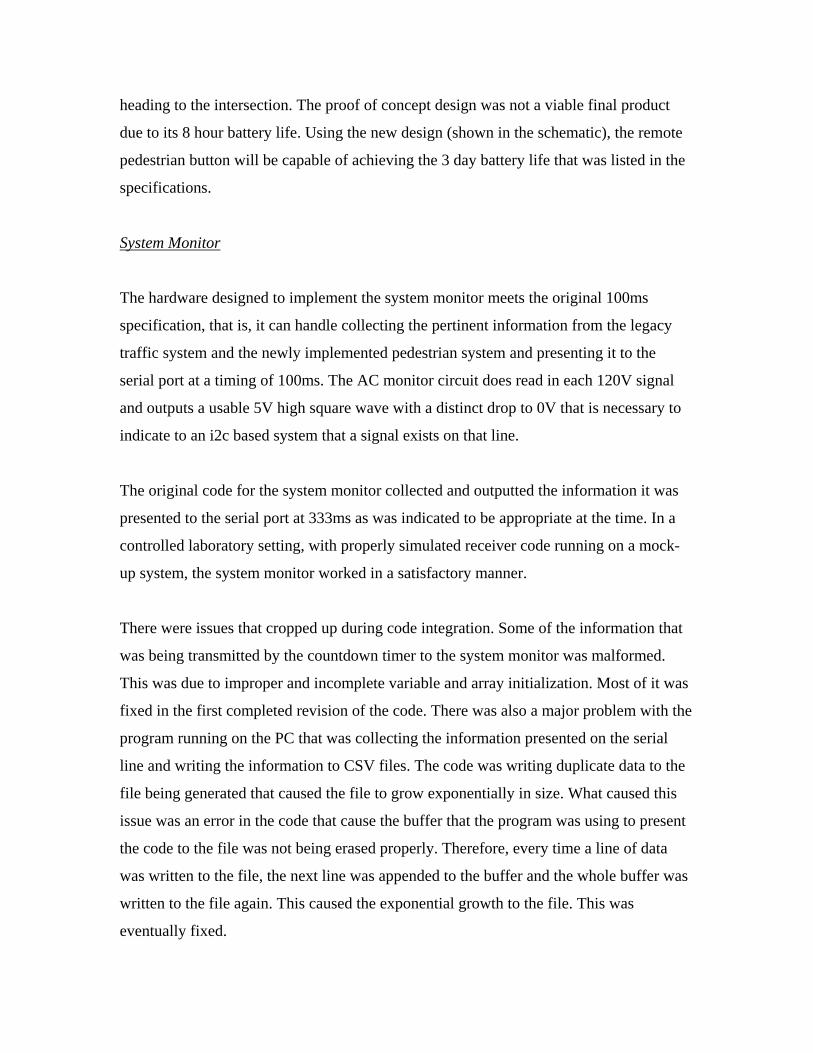
heading to the intersection. The proof of concept design was not a viable final product
due to its 8 hour battery life. Using the new design (shown in the schematic), the remote
pedestrian button will be capable of achieving the 3 day battery life that was listed in the
specifications.
System Monitor
The hardware designed to implement the system monitor meets the original 100ms
specification, that is, it can handle collecting the pertinent information from the legacy
traffic system and the newly implemented pedestrian system and presenting it to the
serial port at a timing of 100ms. The AC monitor circuit does read in each 120V signal
and outputs a usable 5V high square wave with a distinct drop to 0V that is necessary to
indicate to an i2c based system that a signal exists on that line.
The original code for the system monitor collected and outputted the information it was
presented to the serial port at 333ms as was indicated to be appropriate at the time. In a
controlled laboratory setting, with properly simulated receiver code running on a mock-
up system, the system monitor worked in a satisfactory manner.
There were issues that cropped up during code integration. Some of the information that
was being transmitted by the countdown timer to the system monitor was malformed.
This was due to improper and incomplete variable and array initialization. Most of it was
fixed in the first completed revision of the code. There was also a major problem with the
program running on the PC that was collecting the information presented on the serial
line and writing the information to CSV files. The code was writing duplicate data to the
file being generated that caused the file to grow exponentially in size. What caused this
issue was an error in the code that cause the buffer that the program was using to present
the code to the file was not being erased properly. Therefore, every time a line of data
was written to the file, the next line was appended to the buffer and the whole buffer was
written to the file again. This caused the exponential growth to the file. This was
eventually fixed.

Newer specifications that were requested of the system monitor required it to be an event
driven system that monitored the events with an 8ms precision. Physical constraints of
the hardware, including a relatively slow reading of the I/O Expander chips and latency
of the radio communication made this physically impossible. A rewritten version of the
system monitor code attempted to accomplish reading the system as fast as it was
physically possible. It, however, had quite a few issues was wasn’t fully complete. To
make this new specification, new hardware will probably have to be designed with that
kind of resolution in mind.

Economic Analysis
Countdown Timer Part Description Qty Manufacturer Cost/Unit Total
120VAC to 15VDC Wall Wart 1 CUI Inc. 13.63 13.63
LTC3783 LED Drivers 2 Linear Technology 4.07 8.14
26-pin Connector 1 Assmann Electronics 0.83 0.83
BS170 N-channel MOSFETs 16 Fairchild Semi 0.34 5.44
60V N-channel MOSFET 2 STMicroelectronics 0.94 1.88
15m Sense Resistors 4 Ohmite 1.60 6.40
91-ohm 1/4 Watt Resistors 14 Panasonic - ECG 0.17 2.38
2.2K 1/4 Watt Resistors 6 Panasonic - ECG 0.17 1.02
12.4K 1/4 Watt Resistors 2 Yageo Corporation 0.10 0.20
20K 1/4 Watt Resistors 2 Yageo Corporation 0.10 0.20
24.3K 1/4 Watt Resistors 2 Yageo Corporation 0.10 0.20
47K 1/4 Watt Resistors 10 Panasonic - ECG 0.17 1.70
549K 1/4 Watt Resistors 2 Yageo Corporation 0.10 0.20
DC/DC Converter 1 Maxim IC 1.90 1.90
DC/DC Converter 1 Maxim IC 1.90 1.90
DC/DC Converter 1 Maxim IC 1.90 1.90
20K Potentiometer 2 CTS Corporation 0.54 1.08
0.1uF Capacitors 13 BC Components 0.07 0.91
.47uF Capacitors 2 Kemet 0.40 0.80
2.2uF Capacitors 2 BC Components 0.50 1.00
10uF Capacitors 2 BC Components 0.50 1.00
68uF Capacitors 6 BC Components 0.78 4.68
10uH Inductors 2 JW Miller A Bourns 1.00 2.00
100uH Inductor 1 JW Miller A Bourns 1.30 1.30
150uH Inductor 1 JW Miller A Bourns 0.30 0.30
250uH Inductor 1 JW Miller A Bourns 1.40 1.40

B240 Schottky Diode (SMD) 3 Diodes Inc 0.96 2.88
B2100 Schottky Diode (SMD) 2 Diodes Inc 1.16 2.32
16-Pin 0.1" IC Socket 1 Assmann Electronics 0.54 0.54
8-Pin 0.1" IC Socket 3 Assmann Electronics 0.45 1.35
Breakaway Header 0.1" (Strip of 36) 1 Tyco Electronics 1.45 1.45
4-Pin Header 1 FCI 0.80 0.80
Xbee Radio 1 Maxstream Inc. 19.00 19.00
2-Pin Header 3 FCI 0.60 1.80
9XStream OEM RF Module 1 Maxstream Inc. 150.00 150.00
Total: 242.53
Wireless Pedestrian Button Part Description Qty Manufacturer Cost/Unit Total
150pF Ceramic Capacitors 3 Murata Electronics 0.17 0.51
0.1uF Electrolytic Capacitors 2 Panasonic - ECG 0.24 0.48
1uF Electrolytic Capacitor 1 Nichicon 0.22 0.22
0.22uF Electrolytic Capacitor 1 Nichicon 0.20 0.20
15pF 200V Ceramic Capacitors 2 Kemet 0.28 0.56
4.7K 1/6-watt Resistors 6 Yageo Corporation 0.05 0.31
1M 1/6-watt Resistors 6 Yageo Corporation 0.05 0.31
220-ohm 1/6-watt Resistor 1 Yageo Corporation 0.05 0.05
10-ohm 1/6-watt Resistor 1 Yageo Corporation 0.05 0.05
10K 1/6-watt Resistor 2 Yageo Corporation 0.05 0.10
47K 1/6-watt Resistor 1 Yageo Corporation 0.05 0.05
Honeywell Compass Set 1 Honeywell SSEC 45.00 45.00
R-R OP AMP 1 National Semi 0.96 0.96
MOSFET N+P 1 International Rectifier 1.45
1.45
PIC18F452 uC 1 Microchip Tech 10.25 10.25
Xbee Radio 1 Maxstream Inc. 19.00 19.00
CRYSTAL 4.000MHZ 20PF HC-49/US 1 ECS Inc 0.58 0.58
MOSFET P-CH 60V 280MA TO-92 1 Zetex Inc 1.24 1.24
MOSFET N-CH 60V 450MA TO-92 1 Zetex Inc 1.10

1.10
40 pin DIL IC socket 1 Assmann Electronics 0.49 0.49
2mm 10pin Xbee Socket 2 Maxstream Inc. 1.25 2.50
CONN HEADR BRKWAY .100 36POS STR 2 Tyco Electronics 1.45
2.90
Total: 88.32
System Monitor Part Description Qty Manufacturer Cost/Unit Total
IC REMOTE I/O EXPANDER 16-DIP 4 Texas Instruments 1.88 7.52
CAPACITOR .022UF 200V M SERIES 32 Panasonic - ECG 0.17 5.44
DIODE SCHOTTKY 100V 5A DO-204AR 2 Vishay SGI 3.12 6.24
3.3V DC/DC converter 1 Maxim IC 1.90 1.90
5V DC/DC converter 1 Maxim IC 1.90 1.90
9XStream OEM RF Module 1 Maxstream Inc. 150.00 150.00
Total: 173.00
Local Pedestrian Button Part Description Qty Manufacturer Cost/Unit Total
CAP .33UF 16V CERAMIC X7R 0805 1 Panasonic - ECG 0.24 0.24
CAP .1UF 50V CERAMIC Y5V 0603 5 Panasonic - ECG 0.04 0.20
LED 7-SEG .40" 2DGT SUPER RED CC 1 Lite-On Inc 1.20 1.20
CONN HEADER VERT 2POS .100 30AU 2 Tyco 1.26 2.52
CONN HEADER 5POS 0.1 VERT KEYED 1 Molex 0.50 0.50
CONN HEADER VERT 3POS .100 30AU 2 Tyco 0.52 1.04
MOSFET N-CH 50V 200mA SOT-323 2 Diodes Inc 0.55 1.10
RES 330 OHM 1/10W 5% 0805 SMD 8 Panasonic - ECG 0.08 0.64
RES 4.7K OHM 1/10W 5% 0805 SMD 1 Panasonic - ECG 0.08 0.08
IC PROGRAMMABLE SOC SSOP48 1 Cypress Semi ?
IC DVR/RCVR 5V RS232 16 TSSOP 1 STMicroelectronics 2.10 2.10
IC TRANSCEIVER 5V RS232 16 DIP 1 STMicroelectronics 1.95 1.95
Total: 11.57
Miscellaneous

Part Description Qty Manufacturer Cost/Unit Total Econoline ASC/3 Traffic Controller 1 Econolite
Netgear PLC Kit w/ Ethernet Cables 1 Netgear 159.99 159.99
System Monitor PCB #1 3 Quick Turn 36.00 108.00
N.R.E. for System Monitor PCB #1 1 Quick Turn 155.00 155.00
System Monitor PCB #2 3 Quick Turn 31.00 93.00
N.R.E. for System Monitor PCB #2 1 Quick Turn 155.00 155.00
Remote Pedestrian Button PCB 6 Quick Turn 18.00 108.00
N.R.E. for Remote Ped Button PCB 1 Quick Turn 140.00 140.00
Countdown Timer / Driver PCB 6 Quick Turn 50.00 300.00
N.R.E. for Countdown Timer / Driver PCB 1 Quick Turn 155.00 155.00
Local Pedestrian Button PCB 6 Quick Turn 15.00 90.00
N.R.E. for Local Pedestrian Button PCB 1 Quick Turn 155.00 155.00
RabbitCore 3365 Modules 4 Rabbit Semi 105.00 420.00
Total: 2038.99
Total Cost 2554.41
* See Complete Bill of Materials.xls for part numbers and reference designations.

Conclusions and Recommendations
Countdown Timer
Although the countdown timer works correctly as is current implemented, there are a
couple of design issues components currently on the board that should be updated.
The first has to do with the 91-ohm resistors currently in series with the countdown timer
LED segments. As they are implemented right now, these resistors are of the 1/4-watt
style, which is sufficient for proper operation. However, should one of the segments fail,
they will fail short-circuit, which drops all 12 volts across the resistor (assuming the drop
from drain to source on the MOSFET is negligible.) This calculates out to 1.58 watts
being dissipated by a 1/4-watt resistor, which is around six times its physical limit. This
results in burned out resistors as well as burned out LED segments, and possibly a fire
hazard, should anything flammable be around the resistors. Therefore, in future
implementations of this project, a 2-watt 91-ohm resistor should be used in the place of
the 1/4-watt resistor.
Also, the wrong capacitor was used in the driver circuit. On the schematic, a 4.7-
microfarad capacitor is hooked to the INTVCC pin. On the real board, however, a 0.47-
microfarad capacitor was wired in its place. It did not seem to have much effect,
however, it is something to check into.
Assuming that this section of the project is successful in ironing out the bugs from the
previous section there will not be much left to fix on the network end of things until new
devices are added. New devices may bring about new issues that will need to be worked
on, but that would not be something within the scope of our current project.

Local Pedestrian Button
The pedestrian button produced a working smart pedestrian button. The included design
files show a recommended reference design for the wired pedestrian button. Several
changes were made to the printed circuit board developed for the unit. Several changes
were and need to be made to produce a functional board which is described in the product
evaluation. All reference materials used to complete the design are included in Appendix
B. The system needs to be tested in a real pedestrian button environment to validate that
the system will be able to function correctly.
Network
The network is functional, however it is a little bogged down with the constant polling of
the traffic controller. A change to the network messaging that could improve this
situation would be to implement traps on the traffic controller whereby SNMP messages
containing the necessary data will be broadcast to the network without the polling that is
currently necessary. Traps could cut down network communication by up to 66% (one
message rather than three) reducing the network overhead significantly and improving
latency.
Wireless Pedestrian Button
Designing a custom OP AMP circuit with a 200X amplification ratio is not a viable
option. Instead, the HMC6042 should be considered. HMC6042 includes the OP AMP
circuitry inside. Therefore, the amplifier circuit can be mass produced with precision by
the company that builds the compass chip. Also, feed back on the remote should be used
to report the length of the intersection in terms of lanes of traffic and to report when it is
time to cross.

System Monitor
The system monitor hardware is incapable of meeting the tight timing requirements
requested of it in a last minute revision to the specification. The I/O expander chips and
the radio have too great of latency to accomplish this task. The current implementation of
the AC monitoring code sometimes produces false positives. There are occasional times
where it reports, for example, that two traffic lights are on at the same time when it was
visually assessed that it was not the case. This probably has to do with timing issues
when reading from the AC monitor circuit.
To meet these new timing requirements, the hardware will probably have to be re-
evaluated and possibly redesigned. The current I/O expander chips read every 2ms. The
I/O needs to be much quicker. Also, the radio communication has far too much latency in
its current state to meet these requirements.
The code that writes the serial data to files works now, but is quite complex. It can do
more than what is required for it. Something simpler that fit the requirements closer may
have been preferable, but the current code does now do what it is supposed to do.

Appendix A

SNMP get-request Breakdown -- SNMP-Sequence, Length 30 57 -- SNMP-Version: Type (Int), Length, Value 02 01 01 -- Community: Type (String), Length, Value (public) 04 06 70 75 62 6c 69 63 -- Get-Request, length a0 4a -- Request-ID: Type (Int), Length, Value 02 01 01 -- Error Status: Type (Int), Length, Value 02 01 00 -- Error Index: Type (Int), Length, Value 02 01 00 -- Bindings, length 30 3F -- Binding, length of binding 30 13 -- Type (MIB Address), length, Value 06 0f 2b 06 01 04 01 89 36 04 02 01 01 05 01 07 01 -- Variable: Type (NULL), length 05 00 -- Binding, length of binding 30 13 -- Type (MIB Address), length, Value 06 0f 2b 06 01 04 01 89 36 04 02 01 01 02 01 03 02 -- Variable: Type (NULL), length 05 00 -- Binding, length of binding 30 13 -- Type (MIB Address), length, Value 06 0f 2b 06 01 04 01 89 36 03 05 02 01 13 01 03 01 -- Variable: Type (NULL), length 05 00

-- SNMP-Sequence, Length 30 42 -- SNMP-Version: Type (Int), Length, Value 02 01 01 -- Community: Type (String), Length, Value (PUBLIC) 04 06 70 75 62 6c 69 63 -- Get-Request, length a0 4a -- Request-ID: Type (Int), Length, Value 02 01 02 -- Error Status: Type (Int), Length, Value 02 01 00 -- Error Index: Type (Int), Length, Value 02 01 00 -- Bindings, length 30 2a -- Binding, length of binding 30 13 -- Type (MIB Address), length, Value 06 0f 2b 06 01 04 01 89 36 04 02 01 01 04 01 06 01 -- Variable: Type (NULL), length 05 00 -- Binding, length of binding 30 13 -- Type (MIB Address), length, Value 06 0f 2b 06 01 04 01 89 36 04 02 01 01 04 01 07 01 -- Variable: Type (NULL), length 05 00

Appendix B

Appendix B1
Ped Button Printed Circuit Board First Revision


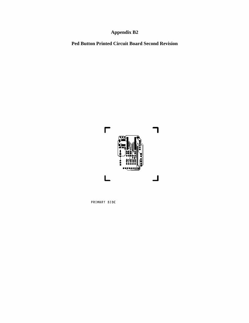
Appendix B2
Ped Button Printed Circuit Board Second Revision


Appendix B3
How to Use Allegro
Refer to
CREATING A BASIC PCB LAYOUT SING THE CADENCE DESIGN SUITE Chris Canine University of Idaho Dept. of Electrical and Computer Engineering Which is included on the smart signals project CD.

Appendix C


Countdown Timer
Part Description Qty Reference on Schematic Vendor Manufacturer Vendor Part # Manufacturer Part # Cost/Unit Total
120VAC to 15VDC Wall Wart 1 15V www.digikey.com CUI Inc. T943-P5P-ND DPS150100U-P5P-TK 13.63 13.63
LTC3783 LED Drivers 2 IC1, IC4 www.linear.com Linear Technology LTC3783EFE LTC3783EFE 4.07 8.14
26-pin Connector 1 SV1 www.digikey.com Assmann Electronics HRP26H-ND AWHW26-G-0202-T-R 0.83
0.83
BS170 N-channel MOSFETs 16 Q1, Q2, Q17-30 www.digikey.com Fairchild Semi BS170-ND BS170 0.34 5.44
60V N-channel MOSFET 2 T1-T2 www.digikey.com STMicroelectronics 497-2765-5-ND STP16NF06L 0.94 1.88
15m Sense Resistors 4 R20, R27, R28 R41 www.digikey.com Ohmite 12FR015E-ND 12FR015E 1.60 6.40
91-ohm 1/4 Watt Resistors 14 R1-R14 www.digikey.com Panasonic - ECG P91.0CACT-ND ERO-S2PHF91R0 0.17 2.38
2.2K 1/4 Watt Resistors 6 R33-R38 www.digikey.com Panasonic - ECG P2.20KCACT-ND ERO-S2PHF2201 0.17 1.02
12.4K 1/4 Watt Resistors 2 R19, R42 www.digikey.com Yageo Corporation 12.4KXBK-ND MFR-25FBF-12K4 0.10 0.20
20K 1/4 Watt Resistors 2 R17, R25 www.digikey.com Yageo Corporation 20.0KXBK-ND MFR-25FBF-20K0 0.10 0.20
24.3K 1/4 Watt Resistors 2 R15, R22 www.digikey.com Yageo Corporation 24.3KXBK-ND MFR-25FBF-24K3 0.10 0.20
47K 1/4 Watt Resistors 10 R16, R24 www.digikey.com Panasonic - ECG P47.0KCACT-ND ERO-S2PHF4702 0.17 1.70
549K 1/4 Watt Resistors 2 R18, R21 www.digikey.com Yageo Corporation 549KXBK-ND MFR-25FBF-549K 0.10 0.20
DC/DC Converter 1 MAX5035A www.maxim-ic.com Maxim IC MAX5035AUPA MAX5035A 1.90 1.90
DC/DC Converter 1 MAX5035B www.maxim-ic.com Maxim IC MAX5035BUPA MAX5035B 1.90 1.90
DC/DC Converter 1 MAX5035C www.maxim-ic.com Maxim IC MAX5035CUPA MAX5035C 1.90 1.90
20K Potentiometer 2 R23, R30 www.digikey.com CTS Corporation 306JC203B-ND 306JC203B 0.54 1.08
0.1uF Capacitors 13 C1-C13 www.digikey.com BC Components BC1148CT-ND K104Z15Y5VE5TL2 0.07 0.91
.47uF Capacitors 2 C14-C15 www.digikey.com Kemet 399-4309-ND C320C474M5U5TA 0.40 0.80
2.2uF Capacitors 2 C16-C17 www.digikey.com BC Components 4085PHCT-ND 2222 021 39228 0.50 1.00

10uF Capacitors 2 C18-19 www.digikey.com BC Components 4066PHCT-ND 2222 021 38109 0.50 1.00
68uF Capacitors 6 C20-C25 www.digikey.com BC Components 4073PHCT-ND 2222 021 38689 0.78 4.68
10uH Inductors 2 L1, L3 www.digikey.com JW Miller A Bourns M8616-ND 6000-100K-RC 1.00 2.00
100uH Inductor 1 L5 www.digikey.com JW Miller A Bourns M9946-ND RL824-101K-RC 1.30 1.30
150uH Inductor 1 L6 www.digikey.com JW Miller A Bourns M8148-ND 79F151K-RC 0.30 0.30
250uH Inductor 1 L7 www.digikey.com JW Miller A Bourns M8273-ND 5254-RC 1.40 1.40
B240 Schottky Diode (SMD) 3 D9-D11 www.digikey.com Diodes Inc B240-FDICT-ND B240-13-F 0.96 2.88
B2100 Schottky Diode (SMD) 2 D7-D8 www.digikey.com Diodes Inc B2100-FDICT-ND B2100-13-F 1.16
2.32
16-Pin 0.1" IC Socket 1 IC2 www.digikey.com Assmann Electronics AE9994-ND A16-LC-TR-R 0.54
0.54
8-Pin 0.1" IC Socket 3 MAX5035A, B, C www.digikey.com Assmann Electronics AE9988-ND A08-LC-TR-R 0.45
1.35
Breakaway Header 0.1" (Strip of 36) 1 U$1, MOD2 www.digikey.com Tyco Electronics A26514-36-ND 4-103327-0-36 1.45
1.45
4-Pin Header 1 JP2 www.digikey.com FCI 609-1319-ND 76384-404LF 0.80 0.80
Xbee Radio 1 U$1 www.digikey.com Maxstream Inc. XB24-AWI-001-ND XB24-AWI-001 19.00 19.00
2-Pin Header 3 JP1, JP3-JP4 www.digikey.com FCI 609-1317-ND 76384-402LF 0.60 1.80
9XStream OEM RF Module 1 MOD2 www.digikey.com Maxstream Inc. X09-009NSC-ND X09-009NSC 150.00 150.00 Total: 242.53 Wireless Pedestrian Button
Part Description Qty Reference on Schematic Vendor Manufacturer Vendor Part # Manufacturer Part # Cost/Unit Total
150pF Ceramic Capacitors 3 C1,C2,C3 www.digikey.com Murata Electronics 490-4259-ND DEBB33A151KC1B 0.17 0.51
0.1uF Electrolytic Capacitors 2 C4,C5 www.digikey.com Panasonic - ECG P5559-ND ECA-1HHG0R1 0.24 0.48
1uF Electrolytic Capacitor 1 C6 www.digikey.com Nichicon 493-1333-ND UVZ1H010MDD 0.22 0.22
0.22uF Electrolytic Capacitor 1 C7 www.digikey.com Nichicon 493-1096-ND UVR1HR22MDD 0.20 0.20
15pF 200V Ceramic 2 C23,C26 www.digikey.com Kemet 399-1889-ND C315C150J2G5CA 0.28

Capacitors 0.56
4.7K 1/6-watt Resistors 6 R1-R5,R7,R8 www.digikey.com Yageo Corporation 4.7KEBK-ND CFR-12JB-4K7 0.05 0.31
1M 1/6-watt Resistors 6 R3,R6,R9,R12-R14 www.digikey.com Yageo Corporation 1.0MEBK-ND CFR-12JB-1M0 0.05 0.31
220-ohm 1/6-watt Resistor 1 R16 www.digikey.com Yageo Corporation 220EBK-ND CFR-12JB-220R 0.05 0.05
10-ohm 1/6-watt Resistor 1 R15 www.digikey.com Yageo Corporation 10EBK-ND CFR-12JB-10R 0.05 0.05
10K 1/6-watt Resistor 2 R10,R11 www.digikey.com Yageo Corporation 10KEBK-ND CFR-12JB-10K 0.05 0.10
47K 1/6-watt Resistor 1 R17 www.digikey.com Yageo Corporation 47KEBK-ND CFR-12JB-47K 0.05 0.05
Honeywell Compass Set 1 U$3,U$4,U$5 www.digikey.com Honeywell SSEC 342-1036-ND HMC1055 45.00 45.00
R-R OP AMP 1 U$6 www.digikey.com National Semi LMV324M-ND LMV324M/NOPB 0.96 0.96
MOSFET N+P 1 U$7 www.digikey.com International Rectifier IRF7509CT-ND IRF7509TR 1.45
1.45
PIC18F452 uC 1 U$1 www.digikey.com Microchip Tech PIC18F452-I/P-ND PIC18F452-I/P 10.25 10.25 Xbee Radio 1 U$2 www.digikey.com Maxstream Inc. XB24-AWI-001-ND XB24-AWI-001 19.00 19.00 CRYSTAL 4.000MHZ 20PF HC-49/US 1 X1 www.digikey.com ECS Inc X405-ND ECS-40-20-4 0.58
0.58
MOSFET P-CH 60V 280MA TO-92 1 Q3 www.digikey.com Zetex Inc ZVP2106A-ND ZVP2106A 1.24
1.24
MOSFET N-CH 60V 450MA TO-92 1 Q2 www.digikey.com Zetex Inc ZVN2106A-ND ZVN2106A 1.10
1.10
40 pin DIL IC socket 1 U$1 www.digikey.com Assmann Electronics AE8940-ND A40-LC-TT 0.49
0.49
2mm 10pin Xbee Socket 2 U$2 www.sparkfun.com Maxstream Inc. PRT-08272 PRT-08272 1.25 2.50
CONN HEADR BRKWAY .100 36POS STR 2 JP1-JP6 www.digikey.com Tyco Electronics A26514-36-ND 4-103327-0-36 1.45
2.90
Total: 88.32 System Monitor
Part Description Qty Reference on Schematic Vendor Manufacturer Vendor Part # Manufacturer Part # Cost/Unit Total
IC REMOTE I/O EXPANDER 16-DIP 4 U$1 - U$4 www.digikey.com Texas Instruments 296-13106-5-ND PCF8574AN 1.88
7.52
10KOhm Resistor 2 R1, R2 www.digikey.com Yageo Corporation 10KEBK-ND CFR-12JB0220R 0.05 0.10
DIODE SCHOTTKY 100V 2 D1, D2 www.digikey.com Vishay SGI 50SQ100-ND 50SQ100 3.12

5A DO-204AR 6.24
3.3V DC/DC converter 1 U$5 maxim-ic.com Maxim IC MAX5035AUPA MAX5035AUPA 1.90 1.90
5V DC/DC converter 1 U$6 maxim-ic.com Maxim IC MAX5035BUPA MAX5035BUPA 1.90 1.90
9XStream OEM RF Module 1 MOD2 www.digikey.com Maxstream Inc. X09-009NSC-ND X09-009NSC 150.00 150.00 RABBITCORE RCM3200 Module 1 MOD1 www.digikey.com Rabbit Semi 316-1097-ND 20-101-0520 89.00 89.00
MAX232AEPE IC 1 IC1 www.digikey.com Maxim IC MAX232AEPE-ND MAX232AEPE 3.51 3.51
1uF 200V Capacitor 4 C1 - C4 www.digikey.com Kemet 399-4521-1-ND C440C105M5U5TA7200 0.84 3.36
CONN DB9 FMALE TIN PLASTIC SHELL 2 X1, X2 www.digikey.com CW Industries CFP09T-ND CWR-181-09-0003 3.60
7.20
47uF 50V Capacitor 4 C5, C8, C9, C12 www.mouser.com TDK 810-FK26Y5V0J476Z FK26Y5V0J476Z 0.24
0.96
1M Ohm Resistor 2 R3, R5 www.digikey.com Yageo Corporation 1.0MEBK-ND CFR-12JB-10R 0.05 0.10
390K Ohm Resistor 2 R4, R6 www.digikey.com Yageo Corporation 390KQBK-ND CFR-25JB-390K 0.05 0.10
0.1uF 50V Capacitor 4 C6, C7, C10, C11 www.mouser.com AVX 581-SA301C104KAR SA301C104KAR 0.12
0.48
100uH Choke 2 L1, L2 www.digikey.com J.W. Miller 542-77F101J-RC 77F101J-RC 0.54 1.08
Total: 273.45 AC Monitor
Part Description Qty Reference on Schematic Vendor Manufacturer Vendor Part # Manufacturer Part # Cost/Unit Total
OPTOCOUPLER 4CH TRANS 16DIP 8 U$1 - U$8 www.digikey.com NEC PS2501-4A-ND PS2501-4-A 1.95 15.60 CAPACITOR .022UF 200V M SERIES 32 C1-C32 www.digikey.com Panasonic - ECG P1045-ND ECQ-M2223KZ 0.17
5.44
DIODE 1N4004 32 D1-D34 www.digikey.com Vishay SGI 1N4004-E3/54GITR-ND 1N4004-E3/54 0.28
8.96
10K Ohm Resistor 32 R1-R32 www.digikey.com Yageo Corporation 10KEBK-ND CFR-12JB0220R 0.05 1.60
Total: 31.60

Wired Pedestrian Button
Part Description Qty Reference on Schematic Vendor Manufacturer Vendor Part # Manufacturer Part # Cost/Unit Total
CAP .33UF 16V CERAMIC X7R 0805 1 C1 www.digikey.com Panasonic - ECG ECJ-2YB1C334K ECJ-2YB1C334K 0.24
0.24
CAP .1UF 50V CERAMIC Y5V 0603 5 C2-C6 www.digikey.com Panasonic - ECG PCC2153CT-ND ECJ-1VF1H104Z 0.04
0.20
LED 7-SEG .40" 2DGT SUPER RED CC 1 D1 www.digikey.com Lite-On Inc 160-1539-5-ND LTD-4708JR 1.20
1.20
CONN HEADER VERT 2POS .100 30AU 2 J1,J5 www.digikey.com Tyco A26564-ND 1-87215-0 1.26
2.52
CONN HEADER 5POS 0.1 VERT KEYED 1 J2 www.digikey.com Molex WM4203-ND 22-23-2051 0.50
0.50
CONN HEADER VERT 3POS .100 30AU 2 J4,J6 www.digikey.com Tyco A30787-ND 3-641215-3 0.52
1.04
MOSFET N-CH 50V 200mA SOT-323 2 Q2,Q1 www.digikey.com Diodes Inc
BSS138W-FDICT-ND BSS138W-7-F 0.55
1.10
RES 330 OHM 1/10W 5% 0805 SMD 8 R3-R10 www.digikey.com Panasonic - ECG P330ACT-ND ERJ-6GEYJ331V 0.08
0.64
RES 4.7K OHM 1/10W 5% 0805 SMD 1 R11 www.digikey.com Panasonic - ECG P4.7KACT-ND ERJ-6GEYJ472V 0.08
0.08
IC PROGRAMMABLE SOC SSOP48 1 U1 www.digikey.com Cypress Semi 428-1521-5-ND CY8C27643-24PVI ? IC DVR/RCVR 5V RS232 16 TSSOP 1 U2 www.digikey.com STMicroelectronics 497-2057-1-ND ST232BTR 2.10
2.10
IC TRANSCEIVER 5V RS232 16 DIP 1 On Dans Board www.digikey.com STMicroelectronics 497-2059-5-ND 497-2059-5-ND 1.95
1.95
Total: 11.57 Miscellaneous
Part Description Qty Reference on Schematic Vendor Manufacturer Vendor Part # Manufacturer Part # Cost/Unit Total
Econoline ASC/3 Traffic Controller 1 None Econolite Econolite ASC/3 ASC/3 Netgear PLC Kit w/ Ethernet Cables 1 None www.newegg.com Netgear N82E16833122168 HDXB101 159.99 159.99 System Monitor PCB #1 3 None www.qtcircuits.com Quick Turn None None 36.00 108.00 N.R.E. for System Monitor PCB #1 1 None www.qtcircuits.com Quick Turn None None 155.00 155.00 System Monitor PCB #2 3 None www.qtcircuits.com Quick Turn None None 31.00 93.00 N.R.E. for System Monitor PCB #2 1 None www.qtcircuits.com Quick Turn None None 155.00 155.00

Remote Pedestrian Button PCB 6 None www.qtcircuits.com Quick Turn None None 18.00 108.00 N.R.E. for Remote Ped Button PCB 1 None www.qtcircuits.com Quick Turn None None 140.00 140.00 Countdown Timer / Driver PCB 6 None www.qtcircuits.com Quick Turn None None 50.00 300.00 N.R.E. for Countdown Timer / Driver PCB 1 None www.qtcircuits.com Quick Turn None None 155.00 155.00 Local Pedestrian Button PCB 6 None www.qtcircuits.com Quick Turn None None 15.00 90.00 N.R.E. for Local Pedestrian Button PCB 1 None www.qtcircuits.com Quick Turn None None 155.00 155.00 RabbitCore 3365 Modules 4 MOD1 Rabbit Semi Rabbit Semi RCM3365 RCM3365 105.00 420.00 Total: 2038.99 Total Cost 2,686.46

Appendix D

Appendix D1
Count Down Timer Flow Diagram
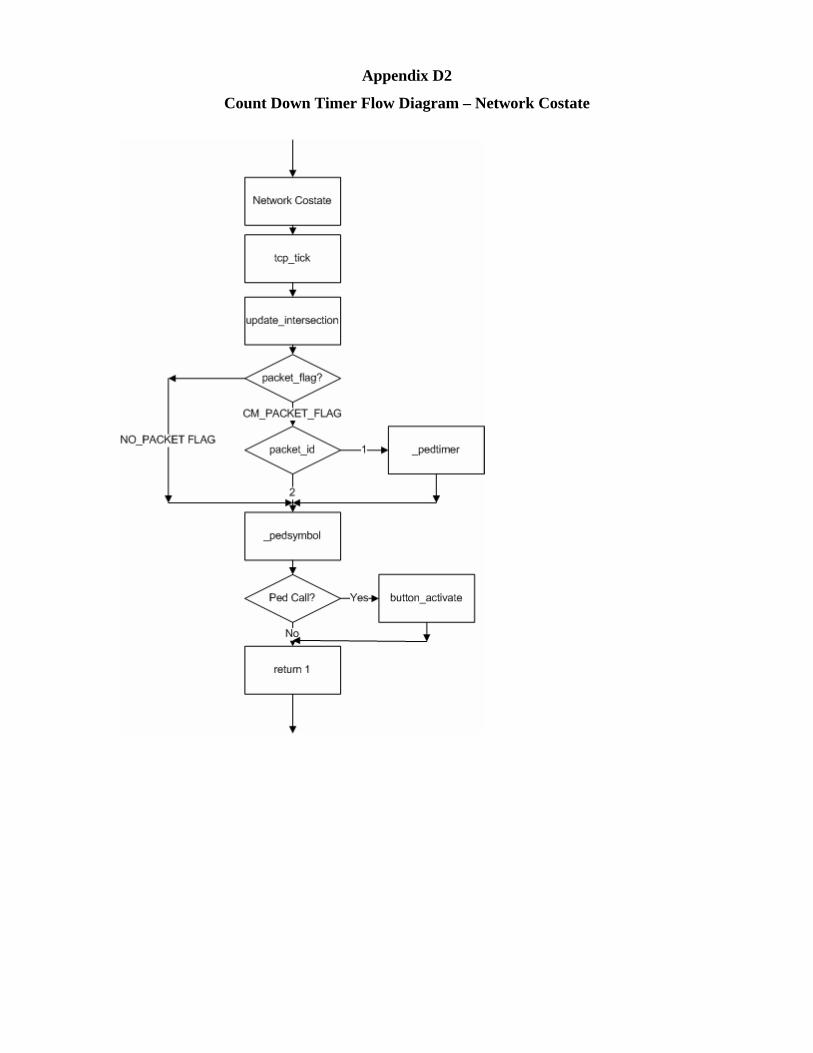
Appendix D2
Count Down Timer Flow Diagram – Network Costate

Appendix D3
Count Down Timer Flow Diagram – Countdown Costate

Appendix D4
Count Down Timer Flow Diagram – Digit Display Costate

Appendix D5
Count Down Timer Flow Diagram – Remote PED Costate

Appendix D6
Count Down Timer Flow Diagram – Observer Costate

Appendix D7
Count Down Timer Flow Diagram – Local PED Receive Costate

Appendix D8
Count Down Timer Flow Diagram – Local PED Send Costate
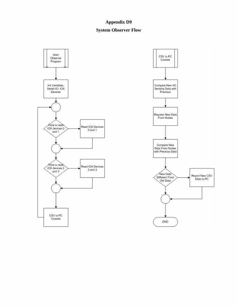
Appendix D9
System Observer Flow

Appendix E

Appendix E1
System Observer Connections

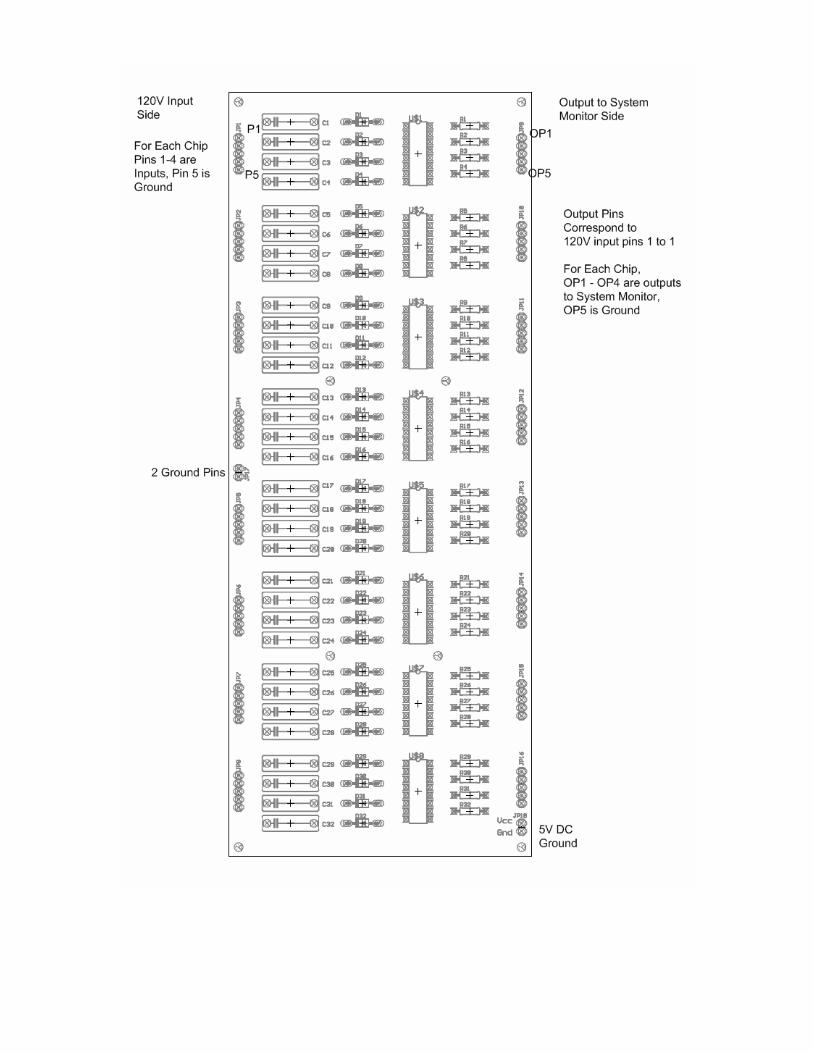
Appendix E2
AC Monitor Connections

Appendix F

Appendix F1
System Collaboration Diagram


Appendix F2
Observer Collaboration Diagram

Appendix G

Appendix G1
Local PED Schematic

Appendix G2
Remote PED Schematic

Appendix G3
Countdown Schematic

Appendix G4
Observer Schematic

Appendix G5
AC Sensing Schematic