Embed Size (px)
Citation preview

SMART-LIFTTM Electric Ceiling Lifts
BEFORE YOU BEGIN .....
• CAUTION: To prevent damage to the ceiling lift, which could affect or void the factory warranty, thor-oughly study all instructions and illustrations before you begin to install or operate the lift. Pay particular attention to the “Important Precautions” on Page 1.
• Because of the size and weight of the lift, Chief Manufacturing recommends that at least two people be available when installing the lift.
• If the lift is to be installed in a plenum rated ceiling, it must be hard wired through the strain relief, control wiring must be Class II, and all open holes in the housing (except joist tabs) must be sealed using foil tape.
• If the lift is to be suspended from the ceiling using a 1-1/2-in. pipe, it must be ordered with a CMA-150 mount bracket that includes a pipe coupler.
• If it is to be installed in a non inverted position (raising up), it must be ordered with an SLB mounting bracket that is custom-designed for the specific projector model referenced on your order.
• If it is to be installed in a suspended ceiling, it must be ordered with a CMA-240 Suspended Ceiling Installation Kit.
• The lift is supplied with a separate controller that can be attached to the frame of the lift, mounted nearby, or placed in a remote location.
• The Model RC-10 Radio Frequency Remote Control or the Model IR-10 Infrared Remote Control is available as an accessory from Chief Manufacturing. The controller is also compatible with many 24V controls from other manu-facturers.
• If you have any questions about this installation, contact Chief Manufacturing at 1-800-582-6480.
I N S T R U C T I O N M A N U A L
The Model SL-100 and SL-150 SMART-LIFT Electric Ceiling Lifts are reliable, heavy-duty, affordably priced video lift mechanisms for LCD/DLP projectors. They are designed for home-theater, conference room, or school applications.
The ceiling lift provides an attractive solution to recess a projector in the ceiling. Or, they can be flush-mounted to a finished ceiling to protect and secure the projector, as in a classroom situation.
Your projector can be securely mounted in an inverted position (shown) or be set in the tray.
Plenum Rating requires use of Class II control wiring, electrically hard wiring the unit, and all open holes in the housing (except joist tabs) must be sealed using foil tape
LOGO
CHIEF MANUFACTURING INC.1-800-582-6480 952-894-6280 FAX 952-894-69188401 EAGLE CREEK PARKWAY, STE. 700SAVAGE, MINNESOTA 55378 USA
PART NO. 8820-000001 (Rev. C)©2000 Chief Manufacturing
www.chiefmfg.comPrinted in USA 06-02

Instruction Manual SMART-LIFT Electric Ceiling Lifts
1
IMPORTANT WARNINGS and CAUTIONS!
WARNING: A WARNING alerts you to the possibility of serious injury or death if you do not follow the instructions.
CAUTION: A CAUTION alerts you to the possibility of damage or destruction of equipment if you do not follow the corre-sponding instructions.
• WARNING: Improper installation can result in serious personal injury! Make sure that the ceiling structural mem-bers can support a redundant weight factor five times the total weight of the equipment. If the ceiling can not support this weight, reinforce the ceiling before installing the lift.
• WARNING: Be aware during the installation that this is a motorized device, and there are pinch points for people and for electrical wiring.
• WARNING: Be aware of the potential for personal injury or damage to the lift if it is not adequately mounted. The lift (without a projector) weighs about 65 lbs (30 kg).
• WARNING: Plenum rating requires the unit to be hard wired through the provided strain relief, use of Class II control wiring, and all open holes in housing (except joist tabs) must be sealed using foil tape.
• WARNING: Be sure the lift is installed square and parallel in all dimensions to avoid personal injury or damage to the lift. Avoid stressing the lift at any time during installation.
• WARNING: Electrical outlets must be installed by a qualified electrician. Follow all electrical codes.
• CAUTION: Test the lift for shipping damage. See “Pretest the lift Before Installing,” on page 3.
• CAUTION: Never close lift while projector is running or while projector is in “cool down” operation.
TOOLS REQUIRED FOR INSTALLATION
• Phillips screwdrivers, No. 1 and No. 2• Electric drill and bit set• Pliers (heavy-duty)• Electrical wire cutter/stripper• If suspended from threaded rods: Socket set with extension
NOTE: Other tools may be required depending on the method of installing the lift in the ceiling.
CONTENTS
DIMENSIONAL DRAWING......................................... 2INSTALLATION .......................................................... 3
Pretest the Lift Before Installing............................ 3Prepare the Ceiling Opening and Install the Lift ... 4Install the Projector on the Lift .............................. 9Adjustments.......................................................... 10Install the Controller.............................................. 11Connect the Control Wiring .................................. 11Connect the Lift to the Power Supply ................... 12
OUTSIDE TERMINAL WIRING EXAMPLES .............. 13INSIDE TERMINAL WIRING EXAMPLES .................. 19TROUBLESHOOTING................................................ 25

2
Instruction Manual SMART-LIFT Electric Ceiling Lifts
F
10.50 9.01 3.742.25
%%c.25
2.89
12.74 4.51
2.39
10.95
4.50
%%c.25
4.00 10.75
10.88
19.50
17.75
3.00
2.00
25.50
8.88
2.00
3X .39
4X3.00
4X.38
21.75TOP
FRONT
SIDE
Joist Tab
Joist Tab

Instruction Manual SMART-LIFT Electric Ceiling Lifts
3
PRETEST THE LIFT BEFORE INSTALLING
IMPORTANT: Before mounting the lift in the ceiling, make the following tests to be sure that it operates properly and has not been damaged in shipping.
1. Carefully inspect the lift for shipping damage. If any damage is apparent, call your carrier claims agent and do not continue with the installation until the carrier has reviewed the damage.
2. Set the lift upside down on a clean, level surface.
NOTE: The lift is supplied with a momentary push button on the end of a cable to help you pretest the operation.
3. Connect the momentary push button cable’s leads to ter-minals #6 and #1 and add a jumper wire (electrical wire about 4 in. long with 1/4 in. stripped at each end) between terminals #2 and #5 on the same terminal block (see Fig. 1, Item P).
4. Plug the lift’s power cord into a 110V 60 Hz or 220V 50 Hz (as appropriate) 15-amp outlet.
NOTE: The lift draws approximately 1.5 amps.
5. Operate the lift much like a garage-door opener: press the button when the lift is at its “top” position and it will move “down”; press again when it is at its “bottom” posi-tion and it will move “up”; press while moving and it will stop.
Use the push button to check that the lift runs to the top and bottom of its travel without any interference that might indicate damage during shipment.
6. Unplug the lift’s power cord.
A. Lift Housing — Mounting AssemblyB. Cradle — Yaw/Pitch/Roll AssemblyC. Drop Carriage — Ceiling Pan AssemblyD. Carriage Guide RodE. Drive Motor AssemblyF. Drive Motor Support BracketsG. Drive ChainH. Idler SprocketsJ. Drive Axle AssemblyK. Support ChainsL. Sprocket Support — Chain Tightener
Bracket AssemblyM. ControllerN. Controller HousingP. External Control Terminal BlockQ. Internal Control Terminal BlockR. Power Input, 110VS. Internal Power Junction, 110V
A
B
C
D
EF
G
H
J
K
L
M, N
P R
S
Figure 1. Smart Lift Parts
Q

4
Instruction Manual SMART-LIFT Electric Ceiling Lifts
PREPARE THE CEILING OPENING AND INSTALL THE LIFT
NOTE: If the lift is to be installed in a non inverted position (raising up from a surface instead of suspended from the ceiling), refer to the instructions supplied with the custom-designed SLB Bracket that is shipped with the lift.
Because of the wide variety of possible mounting situations, Chief Manufacturing can only provide general guidelines for preparing the location where the Smart-Lift will be installed. Study the following information carefully, and adapt it as necessary to fit your specific installation.
• WARNING: Be especially aware of the weight of the lift, and the potential for personal injury or of damage to the lift if it is not adequately mounted. The lift (without a projector) weighs about 65 lbs (30 kg).
The “General Guidelines” below, and the information on the following pages, covers the most common mounting situa-tions:
• Suspended from a pipe that is secured to a structural cross brace in the ceiling
• Suspended from threaded rods that are secured to the structural cross brace
• Side-mounted to the ceiling joists, or secured to a wood framework that is mounted to the joists.
If the lift is to be installed in a suspended ceiling, a CMA-240 Suspended Ceiling Installation Kit is is available as an accessory to fill gap(s) in the ceiling.
General Guidelines• Carefully determine the position of the ceiling opening, and its distance from and orientation toward the screen.
• Prepare a plenum (above the ceiling) that is sufficiently larger than the lift. Be sure to provide adequate space for access to the lift on all sides for installation and for any future maintenance or repair.
WARNING: Improper installation can result in serious personal injury! To avoid such injury, make sure that the ceil-ing structural members can support a redundant weight factor five times the total weight of the equipment you intend to support overhead. If they cannot, the ceiling must be reinforced before you install the lift.
WARNING: Improper installation can result in serious injury! Plenum rated installations require electrically hard wiring the unit through the provided strain relief, the use of Class 2 control wiring, and all open holes in the housing (except joist tabs) must be sealed using foil tape. You must adhere to a all local codes.
WARNING: Have the outlets installed by a qualified electrician. Follow all electrical codes.
• Bring in electrical power for the lift before beginning the installation. Provide a 15-amp service (115V 60 Hz or 230V 50 Hz, as appropriate) above the ceiling. The lift has an 8-ft. power cord with a standard 3-prong receptacle for testing, this cord cannot be used for plenum rated applications. Include an additional outlet if the controller will be mounted inside the ceiling plenum.
NOTE: Additional electrical outlets for portable lighting and electrical tools may be helpful during installation, main-tenance, or repair.
• Preplan where the controller will be installed, and how the control wiring will be routed to the controller.

Instruction Manual SMART-LIFT Electric Ceiling Lifts
5
Installation in a Suspended Ceiling (using threaded rods)WARNING: Plenum rating requires hardwiring through the provided strain relief, use of Class II control wiring, and all open holes in housing (except joist tabs) must be sealed using foil tape. See wiring instructions in this manual and follow all local building and electrical codes.
The lift housing can be suspended from three 3/8-in.-dia. threaded rods (not supplied by Chief Manufacturing) that are secured to a structural cross brace in the ceiling. Insert the rods through the three holes on the top side of the lift hous-ing, and secure them to the housing with two jam nuts (one inside, one outside). See Fig. 2 and Fig. 3.
CAUTION: For smooth and reliable operation, the lift must be installed square and parallel in all dimensions. Avoid stressing the lift at any time during installation.
NOTE: Installing turnbuckles on the threaded rod will make it easier to level the unit.
After installing the lift, use the test push button to carefully operate the lift all the way up and down to be sure the clear-ances are adequate.
Figure 2. Threaded Rod Installation
Jam Nuts
4.00 10.75
10.88
19.50
17.75
3.00
2.00
25.50
8.88
2.00
3X .39
4X3.00
4X.38
21.75
Figure 3. Top View Dimensions

6
Instruction Manual SMART-LIFT Electric Ceiling Lifts
Installation in a Suspended Ceiling (using pipe coupler)An optional pipe coupler (Model CMA-150) is available for suspending the lift housing from a 1-1/2 NPT pipe (Fig. 4).
WARNING: Plenum rating requires hardwiring through the provided strain relief, use of Class II control wiring, and all open holes in housing (except joist tabs) must be sealed using foil tape. See wiring instructions in this manual and follow all local building and electrical codes.
CAUTION: For smooth and reliable operation, the lift must be installed square and parallel in all dimensions. Avoid stressing the lift at any time during installation.
After installing the lift, use the test push button to carefully operate the lift all the way up and down to be sure the clear-ances are adequate.
Coupler CMA150
1 1/2” NPT Pipe
Figure 4. Pipe Coupler Installation

Instruction Manual SMART-LIFT Electric Ceiling Lifts
7
Installation in a Wood Framework (or Side-Mounted to Joists)The lift housing has joist tabs to assist in side-mounting the lift to the ceiling joists or otherwise securing it to a wood framework.
For this method, you should first construct any framework and secure it to the joists, then install the lift as outlined below:
1. Using the same jumper wire and push button used for pretesting (page 2), cycle the lift to its “open” position. This allows access to the inside of the housing and exposes the mounting tabs.
WARNING: Plenum rating requires hardwiring through the provided strain relief, use of Class II control wiring, and all open holes in housing (except joist tabs) must be sealed using foil tape. See wiring instructions in this manual and follow all local building and electrical codes.
2. If you need more space for access to the mounting tabs, remove the ceiling pan:
a. Remove the four plugs, one at each corner of the pan (See Fig. 5), to reveal four small screws.
b. Using a #1 Phillips screwdriver, remove the four screws and remove the ceiling pan.
NOTE: The ceiling-pan screws are primarily used only for removing the pan if there is an electrical problem and the lift can’t be cycled open.
3. Secure the lift to the joists or wood framework. At least six 1/4 x1-1/4-in. lag screws must be driven through the mounting tabs around the inside of the lift housing. There are 10 tab locations, three in each side and two in each end. Refer to Fig. 5 and Fig. 6. The lift only requires support on two opposing sides.
4. Install the ceiling pan and secure the ceiling pan using four screws.
CAUTION: For smooth and reliable operation, the lift must be installed square and parallel in all dimensions. Avoid stressing the lift at any time during installation.
After installing the lift, use the test push button to carefully operate the lift all the way up and down to be sure the clear-ances are adequate.
See Fig. 7 for finishing to match the drywall ceiling,
Figure 5. Joist Mounted Installation
Ceiling Pan
Plugs
Joist Tab

8
Instruction Manual SMART-LIFT Electric Ceiling Lifts
Sheetrock
1/4 Dia. Lag Screw
Lift HousingJoist
Bead Flange Finish Ceiling Compound
NOTE: Bead flange setback allowsfinish compound to hidelift housing seam.
Alternate 1/4 DiaBolt Thru
Figure 7. Drywall Finishing
F
10.50 9.01 3.742.25
%%c.25
2.89
12.74 4.51
2.39
10.95
4.50
%%c.25
Figure 6. Joist Mounting Dimensions
Joist Tab
Joist Tab

Instruction Manual SMART-LIFT Electric Ceiling Lifts
9
INSTALL THE PROJECTOR ON THE LIFT
NOTE: If desired, the projector can also set directly on the bottom plate of the lift and not be secured by the bracket. Maximum projector weight for this application is 35 pounds.
1. If the lift is installed in an inverted position (suspended from the ceiling), attach the SLB adapter bracket (see Fig. 8) to the projector by aligning the threaded holes on the projector with the slots on the bracket and secure it using the screws provided (refer your individual bracket instructions).
2. If you need more space for access to the mounting tabs, remove the ceiling pan as follows:
a. Remove the four plugs (one at each corner of the pan), to reveal four small screws.
b. With a #1 Phillips screwdriver, remove the four screws. The ceiling pan will release.
3. Using the six 10-24 x 1/2-in. studs on the top side of the SLB adapter bracket, align the studs with the holes on the underside of the lift cradle.
4. While holding the projector in place, secure the projector using six nuts.
CAUTION: If cradles adjusted, cradle must be level (matching set of holes must be used on the right and left side of the cradle).
5. Select the appropriate mounting holes for the cradle within the housing:
• On the sides of the lift housing, there are five 3/16-in.-dia. holes in a vertical line that allow for alternate vertical positions of the cradle within the housing.
• There are also three sets of holes 1-3/4 in. apart on each side to accommodate three positions forward-and-back.
6. if necessary, change the position of the cradle
Plugs
Nut
Figure 8. Projector Installation
SLB AdapterBracket

10
Instruction Manual SMART-LIFT Electric Ceiling Lifts
ADJUSTMENTS
To Adjust the Aim of the ProjectorThe aim of the projector can be adjusted in all directions, as shown:
1. Yaw. See Fig. 9. Move the lift to its “down” position. There are four 10-32 x 1/2-in. pan-head screws (two on each side) inside the bottom of the cradle, that secure the left and right horizontal positions. Loosen these screws slightly, move the cradle to the desired position, and retighten the screws.
CAUTION: The pan-head screws MUST be relocated in the matching holes on both sides if you shift positions.
2. Pitch. See Fig. 10. There are four 10-32 x 1/2-in. pan-head screws (two on each side) on the outside of the car-riage. Loosen these screws slightly, tip the carriage in the slotted holes to the desired angle, and retighten the screws.
3. Roll. See Fig. 11. There are four 10-32 x 1/2-in. pan-head screws in U-slots at the upper outside corners of the cradle assembly. Slightly loosen these screws, gently rock the cradle to the desired position, and retighten the screws.
5. Plug the projector’s power cord into the outlet into one of the two outlets inside the lift. One outlet is switched and the other is continuously live.
Adjust the position of the projector for optimum projected image alignment.
Loosen Screw 4 Places
PP
N
Figure 9. Yaw Adjustment
Figure 10. Pitch Adjustment
Figure 11. Roll Adjustment
Roll adjustment screws
Pitch adjustment screws

Instruction Manual SMART-LIFT Electric Ceiling Lifts
11
INSTALL THE CONTROLLER
WARNING: Plenum rating requires hardwiring through the provided strain relief, use of Class II control wiring, and all open holes in housing (except joist tabs) must be sealed using foil tape. See wiring instructions in this manual and follow all local building and electrical codes.
Select the desired location for mounting the controller:
• Attached to the top of the lift,
• Mounted inside the plenum in the ceiling, or
• Remote-mounted.
Refer to the instructions supplied with the controller.
CONNECT THE CONTROL WIRING
Unplug the lift’s power cord. Remove the jumper and push button from the external terminal block that you installed when pretesting the lift (page 2).
WARNING: Plenum rating requires hardwiring through the provided strain relief, use of Class II control wiring, and all open holes in housing (except joist tabs) must be sealed using foil tape. See wiring instructions in this manual and follow all local building and electrical codes.
Connect the control wiring according to the instructions supplied with the controller. Refer also to the wiring examples and terminal function tables on the following pages.
Feed the video and/or communication cable through the 1-3/8-in. dia. hole on the rear of the lift housing, and connect it to the projector. Leave enough slack in the cabling to allow for up and down travel.
If necessary, install a manual push button to control the opening and closing of the lift.
Refer to the controller instructions for connection options. You can use either the internal or external terminal block to control the SMART-LIFT.
NOTE: On the Model 100, both plugs of the internal receptacle are on continuously. On the Model 150, one plug turns on or off per position and one plug stays on continuously.

12
Instruction Manual SMART-LIFT Electric Ceiling Lifts
CONNECT THE LIFT TO THE POWER SUPPLY
WARNING: Plenum rating requires hardwiring through the provided strain relief, use of Class II control wiring, and all open holes in housing (except joist tabs) must be sealed using foil tape. See wiring instructions in this manual and follow all local building and electrical codes.
NOTE: If the lift is cycled up and down repeatedly, the ther-mal overload on the motor will stop operation. Operation will resume when the thermal overload resets (3 to 5 minutes).
Non Plenum Rated Installation1. Plug the lift’s power cord (supplied) into the electrical out-
let in the ceiling plenum.
Plenum Rated InstallationWARNING: A licensed electrician should disconnect and terminate the leads to the power cord receptacle and, using the access holes provided for a strain relief, hard wire the unit to a power source.
WARNING: Failure to disconnect and terminate power leads properly may result in equipment damage or personal injury.
1. Disconnect and terminate the electrical leads from the power cord receptacle at the interior junction box (see Figure 45).
2. Remove the electrical knockout and install the strain relief (provided).
2. Hardwire the unit to a 110V 60 Hz or 230V 50 Hz (as appropriate) 15-amp power source.
Terminate Power Leads
Electrical Junction Boxinside Smartlift
Figure 12. Disconnect and TerminatePower Cord Leads
Instruction Manual SMART-LIFT Electric Ceiling Lifts
13
OUTSIDE TERMINAL WIRING EXAMPLES
The information on the following pages cover the most common wiring options:
• Pushbutton
• Extend/Retract for momentary or latching contacts
• Remote (RC-10)
• 12 Volt out supply
• 24 Volt out supply
• Two dry contact closures
CAUTION: Closing the unit while the projector is running or in the cooling mode will cause premature bulb failure and may dam-age electrical components.
PushbuttonWire for pushbutton operation (Figure 13) as follows:
10
6Use Category II Wiring
5 9
Figure 13. Pushbutton Wiring

14
Instruction Manual SMART-LIFT Electric Ceiling Lifts
1. Install a wire between terminal 5 (extend/retract common) and the ground/common of a power source (5-30 volts). See Figure 14.
Example: Use 12 volt internal power supply terminal #9 as shown in Figure 15.
2. Connect wires from pushbutton to power supply source (5-30 volts) and terminal #6 (extend/retract). See Figure 16.
3. Connect power source.
4. Push the button once and the unit should extend. Push the but-ton during travel and the unit will stop at that location. Push the button after the unit is extended or stopped in mid-travel and the unit will retract.
Figure 16. Pushbutton Connection
Figure 15. 12 Volt Internal Supply Jumper
Figure 14. Extend/Retract Common

Instruction Manual SMART-LIFT Electric Ceiling Lifts
15
Extend/Retract for Momentary or Latching ContactsThese terminals can be used with any latching contacts, momentary contacts, or a wall switch
NOTE: The connection between the ground (#9) and any other ter-minal connection must be broken (open) before completing the next circuit.
Wire for contact operation (Figure 17) as follows:
1. Install a wire between terminal #9 (shown) and contacts or switch (see Figure 18).
2. Connect power source
3. For extend, complete the circuit to terminal #4 (see Figure 19).
4. Make sure circuit to terminal #4 is open and, for service extend, complete the circuit to terminal #11.
5. Make sure circuit to terminal #11 is open and, for retract, com-plete the circuit to terminal #3.
Figure 19. Contacts Connection
Figure 18. Contacts Connection
Use Category II Wiring
Figure 17. Contacts Wiring

16
Instruction Manual SMART-LIFT Electric Ceiling Lifts
Remote (RC-10)
Wire for remote (RC-10) (Figure 20) operation as follows:
1. Install a jumper wire between terminals #2 and terminal #5 (see Figure 21).
2. Connect the white wire of the RC-10 controller unit toterminal #1 (see Figure 22).
3. Connect the red wire of the RC-10 controller unit to terminal #2.
4. Connect the black wire of the RC-10 controller unit to terminal #5.
5. Connect the power source to the lift.
NOTE: If the unit does not activate, check to make sure the 9 volt battery is working and make sure the dip switches in the send-ing unit match the dip switch settings in the controller unit (see Figure 23).
Figure 21. Jumper Connection
White Wire Black Wire
Red Wire
Use Category II Wiring
Figure 20. Remote Wiring Connections
White lead
Black lead
Red lead
Figure 22. Contacts Connection
Figure 23. Dip Switches

Instruction Manual SMART-LIFT Electric Ceiling Lifts
17
12 Volt Out SupplyThis internal power supply can be used to power external devices &/or to initiate specific functions (see Pushbutton operation and Figure 24).
1. Connect one lead to 12 VOLT GROUND (terminal #9).
2. Connect one lead to 12 VOLTS OUT (terminal #10).
24 Volt Out SupplyThis internal power supply can be used to power external devices & remote controllers (see Figure 25).
1. Connect one lead to 24 VOLT COMMON (terminal #2).
2. Connect one lead to 24 VOLTS OUT (terminal #1).
Two Dry Contact ClosuresNOTE: Dry contacts are rated for 1 Amp @ 24 volts.
These contacts can be used to complete circuits to external devices (see Figure 26).
1. Connect one lead to terminal #12 (common).
2. Connect one lead to terminal #14 (closes when unit reaches full extension).
3. Connect one lead to terminal #13 (closes when unit is fully retracted).
Figure 24. 12 Volts
Figure 25. 24 Volts
Figure 26. Dry Contacts

18
Instruction Manual SMART-LIFT Electric Ceiling Lifts
THIS PAGE INTENTIONALLY BLANK

Instruction Manual SMART-LIFT Electric Ceiling Lifts
19
INSIDE TERMINAL WIRING EXAMPLES
The information on the following pages cover the most common wiring options:
• Pushbutton
• Extend and Retract for Switch or Contacts
• Remote (RC-10)
• 12 Volt out supply
• 24 Volt out supply
• Two dry contact closures
• Voltage Sensing
CAUTION: Closing the unit while the projector is running or in the cooling mode will cause premature bulb failure and may dam-age electrical components.
Pushbutton
Wire for pushbutton operation as follows:
1. Install a wire between terminal 5 (extend/retract common) and ground terminal 3 (see Figure 27).
2. Connect one wire from pushbutton to terminal #4 (12 VDC power supply) and the other wire from the pushbut-ton to terminal #6 (extend/retract) (see Figure 28).
With the unit plugged in, push the button once and the unit should extend. Push the button during travel and the unit will stop at that location. Push the button after the unit is extended or stopped in mid-travel and the unit will retract.
Extend and Retract Terminals to be Triggered By Separate Dry ContactsThese terminals can be used with a wall switch or a separate set of dry contacts for dedicated extend and dedicated retract. Momentary contacts are preferable.
NOTE: The connection between the ground (#13) and any other terminal connection must be broken (open) before completing the next circuit.
1. Connect the common to terminal #13 (see Figure 29).
2. Connect the extend to terminal #11 (see Figure 30).
3. Connect the retract to terminal #12 (see Figure 31).
Figure 27. 12 Volt Supply Jumper
Figure 28. Pushbutton Wires
Figure 29. Common for Extend and Retract Contacts
Common
Extend
Figure 30. Extend Contact Wiring
Retract
Figure 31. Retract Contact Wiring

20
Instruction Manual SMART-LIFT Electric Ceiling Lifts
THIS PAGE INTENTIONALLY BLANK
Instruction Manual SMART-LIFT Electric Ceiling Lifts
21
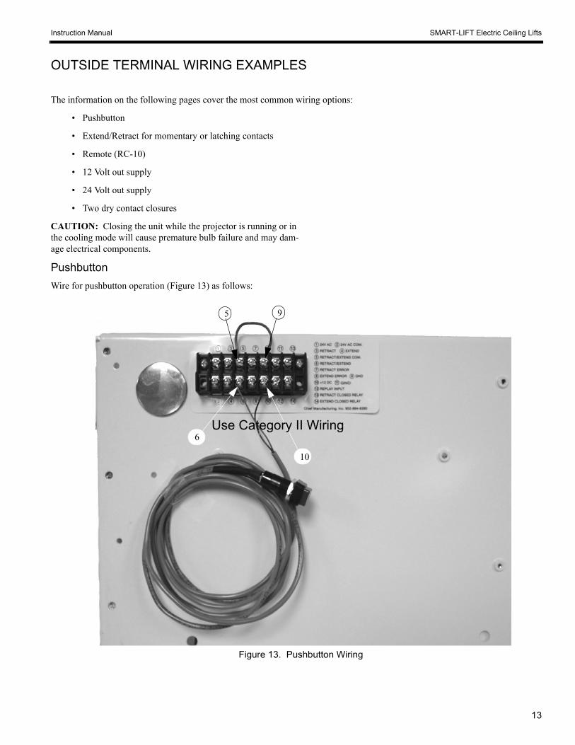
Remote (RC-10)
Wire for remote (RC-10) operation as follows (see Figure 32):
1. Install a jumper wire between terminals #6 and terminal #2 (see Figure 33).
2. Connect the white wire of the RC-10 controller unit toterminal #1 (see Figure 34).
3. Connect the red wire of the RC-10 controller unit to terminal #2.
4. Connect the black wire of the RC-10 controller unit to terminal #5.
5. Connect the power source to the lift.
NOTE: If the unit does not activate, check to make sure the 9 volt battery is working and make sure the dip switches in the send-ing unit match the dip switch settings in the controller unit (see Figure 35).
Figure 33. Contacts Connection
Figure 34. Contacts Connection
Black leadRed lead
RC-10 Controller
Circuit Board Box Assembly
RC-10 Remote
Figure 32. Contacts Connection
Figure 35. Dip Switches

22
Instruction Manual SMART-LIFT Electric Ceiling Lifts
THIS PAGE INTENTIONALLY BLANK

Instruction Manual SMART-LIFT Electric Ceiling Lifts
23
12 Volt Out SupplyThis internal power supply can be used to power external devices &/or to initiate specific functions (see Pushbutton operation and Figure 36).
1. Connect one lead to 12 VOLT GROUND (terminal #3).
2. Connect one lead to 12 VOLTS OUT (terminal #4).
24 Volt Out SupplyThis internal power supply can be used to power external devices & remote controllers (see Figure 37).
1. Connect one lead to 24 VOLT COMMON (terminal #2).
2. Connect one lead to 24 VOLTS OUT (terminal #1).
Two Dry Contact ClosuresNOTE: Dry contacts are rated for 1 Amp @ 24 volts.
These contacts can be used to complete circuits to external devices (see Figure 38 and Figure 39).
1. Connect one lead to terminal #17 (extend limit common).
2. Connect one lead to terminal #16 (closes when unit reaches full extension).
3. Connect one lead to terminal #19 (retract limit common).
4. Connect one lead to terminal #18 (closes when unit is fully retracted).
Low Voltage Sensing1. Connect positive lead (5 - 30 volts AC/DC) to terminal #7
and ground of switching device to terminal #8 (see Figure 40). Unit extends when voltage is sensed, retracts when voltage ceases.
Example using internal 12 volt DC supply (Figure 41):
Service ExtendNOTE: If using latching switch, switch must be disengaged
before initiating any other function.
1. Connect momentary or latching contacts to ground terminal (terminal #3, #10, #13 or #20) and terminal #9 (see Figure 42).
Figure 36. 12 Volts
Figure 37. 24 Volts
Figure 38. Extend Dry Contacts
Figure 39. Retract Dry Contacts
Figure 40. Low Voltage Sensing
1 2 3 4 5 6 7 8
Figure 42. Service Extend
Figure 41. 12 Volt DC Supply

24
Instruction Manual SMART-LIFT Electric Ceiling Lifts
THIS PAGE INTENTIONALLY BLANK

Instruction Manual SMART-LIFT Electric Ceiling Lifts
25
SMART LIFT INTERIOR BOARD BOXTERMINAL FUNCTION DEFINITIONS
TERMINALNUMBER FUNCTION DESCRIPTION WIRING OPTIONS NOTES
1 24 VOLT AC 24 volt AC output
2 24 VOLT ACCOMMON 24 volt AC common
This is an internal power supply forpowering external devices & RemoteControllers.
Chief Mfg. offers the RC-10 RadioFrequency Remote Controller which runsoff of this power supply.
3 GROUND Ground
4 12 VOLT DC 12 volt DC
This is an internal power supply forpowering external devices &/or used forinitiating specific functions(Extend/Retract 5 or Voltage Sensor 7).
5 EXTEND/RETRACT
Initiates movement if lift is static, orstops movement if lift is in motion.Direction of travel will be opposite
of last direction of travel.
Function operates on momentary switchonly.
Operating range is 5 – 30 Volts AC or DC
6EXTEND/RETRACTCOMMON
Used in conjunction withExtend/Retract when using an
external power source to initiatemovement.
To Operate using Internal PowerSourceConnect terminals 3 & 6 withJumper Wire. ConnectMomentary Switch to terminal 4.Connect other line of MomentarySwitch to terminal 5.
To Operate using External PowerSourceConnect External Power Supply’sCommon to terminal 6. Connectinitiating signal to terminal 5.
NOT TO BE USED AS GROUND FORFUNCTION OTHER THANEXTEND/RETRACT TERMINAL 5.
7 VOLTAGESENSOR
When terminal senses voltage, unitwill extend.
When terminal senses cessation ofvoltage, unit will retract.
Operating range is 5 – 30 Volts AC or DC
8VOLTAGESENSOR
COMMON
Used in conjunction with VoltageSensor when using an external
power source to initiate movement.
Voltage SensingConnect positive lead to terminal7. Connect Ground of switchingdevice to terminal 8.
Single-Pull/Throw LatchingSwitchConnect terminals 3 & 8 withJumper Wire. Connect firstSwitch Terminal to terminal 4.Connect other Switch Terminal toterminal 7.
NOT TO BE USED AS GROUND FORFUNCTION OTHER THAN VOLTAGESENSOR TERMINAL 7.
9 SERVICEEXTEND
Extends unit to maximum limit,bypassing normal-use travel setting.
Often used for servicing projectorsin ceiling lifts.
Momentary or Latching contact toGround terminals 3, 10, 13, or 20.
Feature not available on all models.
If using Latching Switch, be sure todisengage Switch prior to initiating anyother function.
10 GROUND Ground
26
Instruction Manual SMART-LIFT Electric Ceiling Lifts
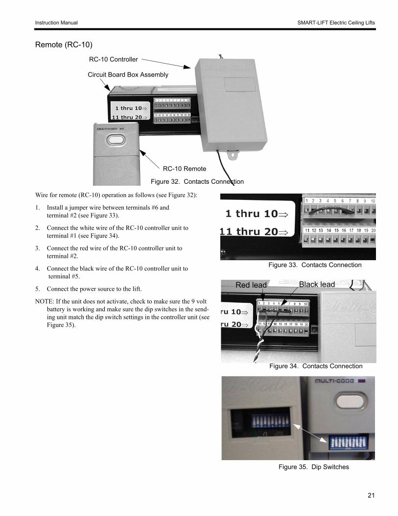
11 EXTEND Extends unit to preset travel limit.If using Latching Switch, be sure todisengage Switch prior to initiating anyother function.
12 RETRACT Retracts unit to preset travel limit.
Momentary or Latching contact toGround terminals 3, 10, 13, or 20. If using Latching Switch, be sure to
disengage Switch prior to initiating anyother function.
13 GROUND Ground
14 EXTENDERROR
Immediately reverses direction oftravel when triggered while unit is
extending.
15 RETRACTERROR
Immediately reverses direction oftravel when triggered while unit is
retracting.
Momentary contact to Groundterminals 3, 10, 13, or 20.
Chief Mfg. offers the SS-10 PressureSensitive Safety Strip to provide thisfunction.Please specify how many inches requiredspanning entire pinch zone.The SS-10 must be ordered with the ST-15Terminals.
16EXTEND
LIMITRELAY
17EXTEND
LIMITRELAY
COMMON
Closes set of internal dry contactswhen unit reaches full extension. RATED FOR 1 AMP @ 24 VOLTS
18RETRACT
LIMITRELAY
19RETRACT
LIMITRELAY
COMMON
Closes set of internal dry contactswhen unit reaches full retraction.
RATED FOR 1 AMP @ 24 VOLTS
20 GROUND Ground
WIRING THE RC-10 Connect white lead to terminal 1, red lead to terminal 2, and black lead toterminal 5. Place jumper wire from terminal 2 to terminal 6
WIRING A MOMENTARY PUSH BUTTON Connect terminals 3 & 6 with Jumper Wire. Connect Momentary Switchto terminal 4. Connect other line of Momentary Switch to terminal 5.

Instruction Manual SMART-LIFT Electric Ceiling Lifts
27
This Page Intentionally Blank

28
Instruction Manual SMART-LIFT Electric Ceiling Lifts
SMART LIFT EXTERIOR 14 PIN TERMINAL FUNCTION DEFINITION
TERMINALNUMBER FUNCTION DESCRIPTION WIRING OPTIONS NOTES
1 24 VOLT AC 24 volt AC output
2 24 VOLT ACCOMMON 24 volt AC common
This is an internal power supply forpowering external devices & RemoteControllers.
Chief Mfg. offers the RC-10 RadioFrequency Remote Controller which runsoff of this power supply.
3 RETRACT Retracts unit to preset travel limit.
If using Latching Switch, be sure todisengage Switch prior to initiating anyother function.
4 EXTEND Extends unit to preset travel limit.
Momentary or Latching contact toGround terminals 9, or 11. If using Latching Switch, be sure to
disengage Switch prior to initiating anyother function.
5EXTEND/RETRACTCOMMON
Used in conjunction withExtend/Retract when using an
external power source to initiatemovement.
NOT TO BE USED AS GROUND FORFUNCTION OTHER THANEXTEND/RETRACT TERMINAL 5.
6 EXTEND/RETRACT
Initiates movement if lift is static, orstops movement if lift is in motion.Direction of travel will be opposite
of last direction of travel.
To Operate using Internal Power Source Connect terminals 9 & 5 withJumper Wire. ConnectMomentary Switch to terminal10. Connect other line ofMomentary Switch to terminal 6.
To Operate using External Power Source Connect External Power Supply’sCommon to terminal 5. Connectinitiating signal to terminal 6.
Function operates on momentary switchonly.
Operating range is 5 – 30 Volts AC or DC
7 RETRACTERROR
Immediately reverses direction oftravel when triggered while unit is
retracting.
8 EXTENDERROR
Immediately reverses direction oftravel when triggered while unit is
extending.
Momentary contact to Groundterminals 9, or 11.
Chief Mfg. offers the SS-10 PressureSensitive Safety Strip to provide thisfunction.Please specify how many inches requiredto span entire pinch zone.The SS-10 must be ordered with the ST-15Terminals.
9 GROUND Ground
10 12 VOLT DC 12 volt DC
This is an internal power supply forpowering external devices &/or used forinitiating specific functions(Extend/Retract 6).
11 GROUND Ground

Instruction Manual SMART-LIFT Electric Ceiling Lifts
29
12LIMIT
RELAYCOMMON
13RETRACT
LIMITRELAY
Closes set of internal dry contactswhen unit reaches full retraction.
14EXTEND
LIMITRELAY
Closes set of internal dry contactswhen unit reaches full extension.
RATED FOR 1 AMP @ 24 VOLTS
WIRING THE RC-10Connect white lead to terminal 1, red lead to terminal 2, and black lead to terminal 6.Place jumper wire from terminal 2 to terminal 5
WIRING A MOMENTARY PUSH BUTTONConnect terminals 9 & 5 with Jumper Wire. Connect Momentary Switch to terminal10. Connect other line of Momentary Switch to terminal 6.

30
Instruction Manual SMART-LIFT Electric Ceiling Lifts
TROUBLESHOOTING
If the lift is installed according to these instructions, it should operate trouble-free indefinitely. If you do encounter a problem, and it isn’t covered by the troubleshooting suggestions below, call the Technical Services Department at Chief Manufacturing:
1-800-582-6480
952-894-6280
Symptom(s)PossibleCauses Suggested ActionNo Power 1. Check power to unit (supply, cord, activation
control, and connections).No power: Provide power, repair cord, tighten
connections or repair activation control.Power: Check fuse on circuit board. If fuse is OK,
proceed to next step.
No Movement and NoSound
Faulty Circuit Board 2. Check circuit board as follows:Make three jumper wires with ends stripped.Install one jumper wire on terminal 11.Install one jumper wire on terminal 12.Install one jumper wire on terminal 13.Momentarily touch jumper wire from terminal 11 toterminal 13. Unit should extend.Momentarily touch jumper wire from terminal 12 toterminal 13. Unit should retract.
ActivatesIn bothDirections: Circuit board OK, faulty activation
interface. Check remote switch, circuit, orbatteries in remote control.
UnitFailsBoth/EitherDirection: Call Chief Manufacturing.
Unit Operates Noisily(Squeeling or grinding)
Track Misalignment 1. Check for noise and/or metal shavings in trackNoise orShavings: Check and adjust track and/or shelf as
necessary.No TrackNoise: Possible brake problem, call Chief
Manufacturing