Embed Size (px)
Citation preview

135
SMART IDS: An Enhanced Network Security Model in IP-MPLS Based
Virtual Private Network
1K.C. Okafor, 2C.C. Okezie, 3C.C. Udeze, 4N. Okwuelu 1,3&4Electronics and Computer Engineering Department
Nnamdi Azikiwe University
Awka, Nigeria
2R & D Department
Electronics Development Institute (FMST-NASENI)
Awka, Nigeria
[email protected], [email protected],[email protected], [email protected]
1Corresponding author
ABSTRACT Contemporary, global cyber terrorism via the internet have changed the landscape of security implementations in cooperate organizations.
This paper discusses analyses and develops novel security architecture for secure transactions in Virtual Private Network (VPN)
environments. Open standard VPN has been in use for a long time without addressing the security holes in VPN wired and wireless
networks. Several proposals have been made in the context of enhanced intrusion detection system (IDS) and reliable VPN design which is
presumed to provide an in depth solution that guarantees secure operations of the enterprise network. However, this work presents SMART
Network Security System (SNSS) which is shown to be very reliable and supports multiple functionalities for both LAN and WLAN VPN
setups. The SNSS models have a Multilayer Access Point Intrusion Detection System (MAPIDS) sensor for monitoring traffic and network
behavior. Also, cryptographic security features viz: authentication, confidentiality, integrity and auto-replay characterize the model. As
such, the system is developed for multiple integration and cost effectiveness in its deployment. Performance parameters such IP VPN
tunnel delay, packet traffic throughput effects, and ping response times (ICMP) were analyzed. The modeling and simulation was executed
with OPNET IT Guru application while generating our validation plots in the network model.
Keywords: VPN, Novel, IDS, cryptographic, security, L2VPNS, MPLS, SNSS
African Journal of Computing & ICT Reference Format: K.C. Okafor, C.C. Okezie, C.C. Udeze, N. Okwuelu (2013). SMART IDS: An Enhanced Network Security Model in IP-MPLS Based Virtual Private
Network. Afr J. of Comp & ICTs. Vol 6, No. 3. Pp135-146
1. INTRODUCTION
This research develops an enhanced security model for
enterprise VPN known as Self Monitoring, Analysis and
Reporting Technology Intrusion Detection System (SMART
IDS). The model leverages on enhanced IP/MPLS internet
backbone for data tunneling. According to [1], Intrusion
detection is the act of detecting unwanted traffic on a network or
a device. An IDS can be a piece of installed software or a
physical appliance that monitors network traffic in order to
detect unwanted activity and events such as illegal and
malicious traffic, traffic that violates security policy, and traffic
that violates acceptable use policies. Many IDS tools will store a
detected event in a log to be reviewed at a later date or will
combine events with other data to make decisions regarding
policies or damage control [1]. As organizations are in dear need
of scalable and secure communication path for their business
processes, virtual private network (VPN) on-site or off-site
(collocation facility) offers a viable solution. A VPN is a virtual
network, built on top of existing physical networks that can
provide a secure communications mechanism for data and other
information transmitted between two endpoints [2]. Because a
VPN can be used over existing networks such as the Internet, it
can facilitate the secure transfer of sensitive data across public
networks (internet) [2]. VPN maintains data privacy through the
use of a tunneling protocol and security procedures.
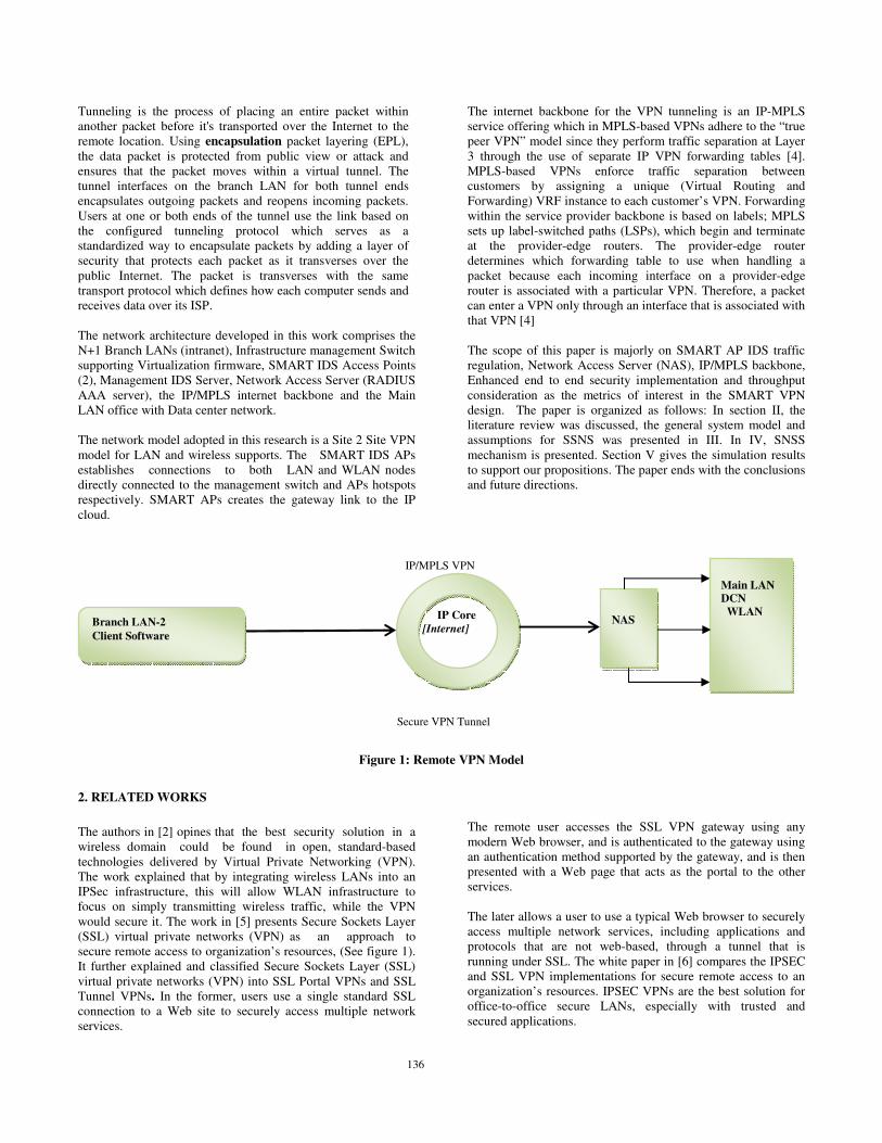
This work focused on the two most common types to develop
our model viz: Remote access VPN and site-to-site VPN. The
Remote Access VPN configuration is used to allow VPN
software clients such as mobile users to securely access
centralized network resources that reside behind a VPN server
[3], as shown in figure 1. The site-to-site VPN allows creating
dedicated, secure connections between locations across the open
Internet or public connection. They can be either Intranet-based
or Extranet-based. In its simplest form, by encrypting data while
it is sent and decrypting it at the receiver, the data is effectively
sent through a tunnel that cannot be entered by data that is not
properly encrypted in the communications process [2]. It
involves placing a packet within another packet and sending it
over a network. The protocol of the outer packet is understood
by the network at both points, called tunnel interfaces, where the
packet enters and exits the network [3]. Figure 2 shows the site-
to-site VPN model.
Basically, this work models a SMART VPN for secure
transaction that rely on tunneling to create a private network
that reaches remote locations via the Internet. Data file from
branch LAN is broken into a series of packets to be sent and
received by computers connected via Internet.
136
Tunneling is the process of placing an entire packet within
another packet before it's transported over the Internet to the
remote location. Using encapsulation packet layering (EPL),
the data packet is protected from public view or attack and
ensures that the packet moves within a virtual tunnel. The
tunnel interfaces on the branch LAN for both tunnel ends
encapsulates outgoing packets and reopens incoming packets.
Users at one or both ends of the tunnel use the link based on
the configured tunneling protocol which serves as a
standardized way to encapsulate packets by adding a layer of
security that protects each packet as it transverses over the
public Internet. The packet is transverses with the same
transport protocol which defines how each computer sends and
receives data over its ISP.
The network architecture developed in this work comprises the
N+1 Branch LANs (intranet), Infrastructure management Switch
supporting Virtualization firmware, SMART IDS Access Points
(2), Management IDS Server, Network Access Server (RADIUS
AAA server), the IP/MPLS internet backbone and the Main
LAN office with Data center network.
The network model adopted in this research is a Site 2 Site VPN
model for LAN and wireless supports. The SMART IDS APs
establishes connections to both LAN and WLAN nodes
directly connected to the management switch and APs hotspots
respectively. SMART APs creates the gateway link to the IP
cloud.
The internet backbone for the VPN tunneling is an IP-MPLS
service offering which in MPLS-based VPNs adhere to the “true
peer VPN” model since they perform traffic separation at Layer
3 through the use of separate IP VPN forwarding tables [4].
MPLS-based VPNs enforce traffic separation between
customers by assigning a unique (Virtual Routing and
Forwarding) VRF instance to each customer’s VPN. Forwarding
within the service provider backbone is based on labels; MPLS
sets up label-switched paths (LSPs), which begin and terminate
at the provider-edge routers. The provider-edge router
determines which forwarding table to use when handling a
packet because each incoming interface on a provider-edge
router is associated with a particular VPN. Therefore, a packet
can enter a VPN only through an interface that is associated with
that VPN [4]
The scope of this paper is majorly on SMART AP IDS traffic
regulation, Network Access Server (NAS), IP/MPLS backbone,
Enhanced end to end security implementation and throughput
consideration as the metrics of interest in the SMART VPN
design. The paper is organized as follows: In section II, the
literature review was discussed, the general system model and
assumptions for SSNS was presented in III. In IV, SNSS
mechanism is presented. Section V gives the simulation results
to support our propositions. The paper ends with the conclusions
and future directions.
Figure 1: Remote VPN Model
2. RELATED WORKS
The authors in [2] opines that the best security solution in a
wireless domain could be found in open, standard-based
technologies delivered by Virtual Private Networking (VPN).
The work explained that by integrating wireless LANs into an
IPSec infrastructure, this will allow WLAN infrastructure to
focus on simply transmitting wireless traffic, while the VPN
would secure it. The work in [5] presents Secure Sockets Layer
(SSL) virtual private networks (VPN) as an approach to
secure remote access to organization’s resources, (See figure 1).
It further explained and classified Secure Sockets Layer (SSL)
virtual private networks (VPN) into SSL Portal VPNs and SSL
Tunnel VPNs. In the former, users use a single standard SSL
connection to a Web site to securely access multiple network
services.
The remote user accesses the SSL VPN gateway using any
modern Web browser, and is authenticated to the gateway using
an authentication method supported by the gateway, and is then
presented with a Web page that acts as the portal to the other
services.
The later allows a user to use a typical Web browser to securely
access multiple network services, including applications and
protocols that are not web-based, through a tunnel that is
running under SSL. The white paper in [6] compares the IPSEC
and SSL VPN implementations for secure remote access to an
organization’s resources. IPSEC VPNs are the best solution for
office-to-office secure LANs, especially with trusted and
secured applications.
Secure VPN Tunnel
IP/MPLS VPN
NAS
IP Core
[Internet]
Main LAN
DCN
WLAN
Branch LAN-2
Client Software

137
The authors in this work agrees with the views of [6] since in a
site to site VPN, this allows the greatest flexibility while
maintaining high security. The sampled literature in [7]
discusses VPN in the context of economics of communications
and communications privacy at large. In a VPN setup, intrusion
detection system (IDS) model can be host-based IDS (HIDS) or
network-based IDS (NIDS) [8]. HIDS is installed at a host to
periodically monitor specific system logs for patterns of
intrusions. In contrast, an NIDS sniffs the traffic to analyze
suspicious behaviors. A signature-based NIDS (SNIDS)
examines the traffic for patterns of known intrusions. SNIDS
can quickly and reliably diagnose the attacking techniques and
security holes without generating an over-whelming number of
false alarms because SNIDS relies on known signatures.
However, anomaly-based NIDS (ANIDS) detects unusual
behaviors based on statistical methods. ANIDS could detect
symptoms of attacks without specific knowledge of details [8].
The authors in [9] discusses how the integrated security gateway
can be implemented using the open source packages. Ron Gula
[10] presents the vulnerability correlation with the IDS alerts
and specifies two methods of correlating the vulnerability with
the IDS alerts
From our sample surveys, this paper argues that a VPN model
with an enhanced security specification can establish secured
virtual links among different organizations via an IP/MPLS
internet backbone. Packet Tunneling facilitates the virtual
lease line while cryptographic technologies prevent private
information passing through the public Internet from being
hijacked. However, when complex cryptographic algorithms
are adapted for encryption and decryption within VPN
tunnels, it creates a cost overhead for such design models.
Consequently, this paper presents a SMART IDS model over
an IP/MPLS backbone to enhance security, maximize
throughput, minimize the latency and reduce deployment cost
as shown in figure 3. Modern VPN technologies such as
PPTP, L2TP, and IPSec PPTP and L2TP work at the data link
layer and are suitable for secure remote access between
mobile users and enterprises and it’s integrated into modern
AP routers. In contrast, IPSec works at the network layer.
3. SYSTEM DESIGN AND ASSUMPTIONS
A. System Model The high performance SMART IDS VPN model in this
research takes cognizance of throughput effects, latency, IP
tunnel delay and ping response times for each branch LAN and
WLAN for tunnel interfaces shown in Fig. 3. It assumed that
the management switch supports virtualization partitioning for
all interfaces. Also the SMART AP is a composite powerful
intelligent monitoring device combined with radio which acts
as a sensor, traffic analyzer/optimizer with user interface
authentication. The throughput model developed by [11]
provides an accurate and simple analytical model for a finite
number of terminals and ideal channel conditions. The
probability that each node in the branch LAN transmits is
given by
Where, p is the conditional collision probability and m is
maximum backoff stage, also b0,0 is expressed as:
b0,0 =
Where W is the contention window.
An infinite population model was assumed in this work for our
terminal LANs, but not stated outrightly. New data packets were
generated according to a Poisson process with rate λ packets.
Hence, the following performance indices were derived for all
the tunnel interfaces.
The total throughput of channel is given as:
1
/M
o i i
i
S T S T=
= ∑
Where, oT = time needed to transmit a packet on a single
broadcast channel
M = parallel broadcast channels, i
i oS Tλ=
Ti = time needed to transmit a packet on an i broadcast channel
Where, λ = packets/s according to Poisson process
Throughput of non-persistent branch tunnel interface is given
viz:
/
/1 1 3
i
i
aG M
ii
aG Mo oi i
o o
GeS S
a aG e G
M MT M MT
σ σ
−
−
= =
+ − − + +
(5)
Where, iG = offered traffic in the ith channel, M = numbers of
parallel link channels, σ = length of jammed time after
collision, oa = normalized propagation delay
oT = time needed to transmit a packet on a single broadcast
channel with bandwidth Wi.
Throughput of a random choice carrier sense multiple access
with collision detection CSMA-CD-RC
(3)
(4)

138
/
/1 1 3
aG M
i
aG Mo o
o o
GeS S
a aG e G
M MT M MT
σ σ
−
−
= =
+ − − + +
(6)
( )1 2 1o ii o o o ii o o
G GD P M X a P X M a
S Sτ
= − + + + + − + +
(7)
Where, Do = average packet delay normalized tooT ,
G = offered traffic in the ith channel
S = throughput, iiP = the probability that a station senses
the chosen channel idle, M = numbers of parallel link
channels, oX = average transmission delay normalized to
To
oτ = acknowledgement time normalized to To,
oa = normalized propagation delay
The branch LANs were assumed to be a continuous
time CSMA/CD (carrier sense multiple access with
collision detection) system with a finite number of
homogeneous Stations, each possessing an infinite buffer.
The system was decomposed and approximately treats each
LAN as an independent M/G/1 queuing system. With this
analysis, the mean traffic delay can be numerically
obtained.
Conclusively, the stability of the system becomes more
sensitive to the retransmission interval as the number of
LAN nodes increases, [12].
B. Queue Stability
The M/G/1 queuing system model was adopted to perform
this task and consequently, the expression was illustrated
thus:
)(11
DT +−≤λγ
(8)
Where, γ = exponential distribution parameter, λ =
Poisson process parameter, T + D = service time
The Laplace-Stieltjes transform (LST) of service time
distribution function *
1G (S) = b1 exp [-S (T + D)] + (1 – b1) G*(s) (9)
Where, b1 = the probability that a node senses an idle
tunnel interface and succeeds in transmission
T = transmission time of a data packet
D = maximum propagation delay
The probability generating function of the stationary queue
length distribution at arbitrary constant is given as:
L (z) = P0
)(
)()(*
2
*
2
*
1
zGz
zGzzG
λλ
λλλλ
−−
−−− (10)
Where, P0 = probability of passive node in the system model
at traffic arrival instant, Hence,
R = L / λ (11)
Where, R = mean response time, L = mean queue length.
Figure 3: Proposed SNSS Model For IP/MPLS VPN
2
IDS
MANG
T
Server
Pix
Firewall
NAS
IP Core
[Internet]
Mai
n
LAN
Branch
LAN-1
Branch
LAN-2
Branch
LAN-3
T
U
N
N
E
L
L
ManGT
Switch
SMART
IDS-AP
SMART
IDS-AP
FTP/WEB
SERVER
Branch
LAN-n+1
1
3
4
RADIUS
AAA
VPN
Sites/Clients
IP/MPLS
139
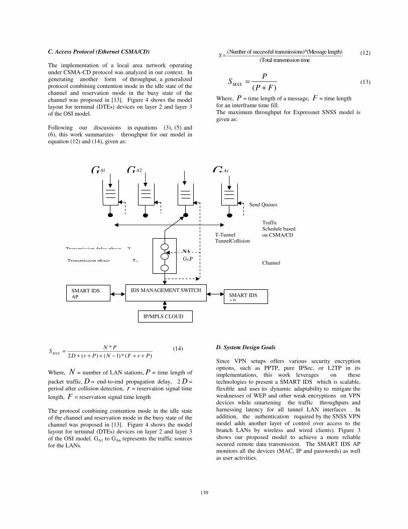
C. Access Protocol (Ethernet CSMA/CD)
The implementation of a local area network operating
under CSMA-CD protocol was analyzed in our context. In
generating another form of throughput, a generalized
protocol combining contention mode in the idle state of the
channel and reservation mode in the busy state of the
channel was proposed in [13]. Figure 4 shows the model
layout for terminal (DTEs) devices on layer 2 and layer 3
of the OSI model.
Following our discussions in equations (3), (5) and
(6), this work summarizes throughput for our model in
equation (12) and (14), given as:
(Number of successful transmissions)*(Message length)
(Total transmission timeS = (12)
( )
MAX
PS
P F=
+ (13)
Where, P = time length of a message, F = time length
for an interframe time fill.
The maximum throughput for Expressnet SNSS model is
given as:
*
2 ( ) ( 1) * ( )MAX
N PS
D r P N F r P=
+ + + − + +
(14)
Where, N = number of LAN stations, P = time length of
packet traffic, D = end-to-end propagation delay, 2 D =
period after collision detection, r = reservation signal time
length, F = reservation signal time length
The protocol combining contention mode in the idle state
of the channel and reservation mode in the busy state of the
channel was proposed in [13]. Figure 4 shows the model
layout for terminal (DTEs) devices on layer 2 and layer 3
of the OSI model. GA1 to GAn represents the traffic sources
for the LANs.
D. System Design Goals
Since VPN setups offers various security encryption
options, such as PPTP, pure IPSec, or L2TP in its
implementations, this work leverages on these
technologies to present a SMART IDS which is scalable,
flexible and uses its dynamic adaptability to mitigate the
weaknesses of WEP and other weak encryptions on VPN
devices while smartening the traffic throughputs and
harnessing latency for all tunnel LAN interfaces . In
addition, the authentication required by the SNSS VPN
model adds another layer of control over access to the
branch LANs by wireless and wired clients). Figure 3
shows our proposed model to achieve a more reliable
secured remote data transmission. The SMART IDS AP
monitors all the devices (MAC, IP and passwords) as well
as user activities.
SMART IDS
AP
SMART IDS
AP
IP/MPLS CLOUD
IDS MANAGEMENT SWITCH
GA11
λ G A22
λ
GAi
NA
GTiP
T-Tunnel
TunnelCollision
Transmission delay phase TDi
Transmission phase TTi
Send Queues
Traffic
Schedule based
on CSMA/CD
Channel

140
*
2 ( ) ( 1) * ( )MAX
N PS
D r P N F r P=
+ + + − + +
(14)
Where, N = number of LAN stations, P = time length of
packet traffic, D = end-to-end propagation delay, 2 D =
period after collision detection, r = reservation signal time
length, F = reservation signal time length. The protocol
combining contention mode in the idle state of the channel
and reservation mode in the busy state of the channel was
proposed in [13]. Figure 4 shows the model layout for
terminal (DTEs) devices on layer 2 and layer 3 of the OSI
model. GA1 to GAn represents the traffic sources for the
LANs.
E. System Design Goals
Since VPN setups offers various security encryption
options, such as PPTP, pure IPSec, or L2TP in its
implementations, this work leverages on these
technologies to present a SMART IDS which is scalable,
flexible and uses its dynamic adaptability to mitigate the
weaknesses of WEP and other weak encryptions on VPN
devices while smartening the traffic throughputs and
harnessing latency for all tunnel LAN interfaces . In
addition, the authentication required by the SNSS VPN
model adds another layer of control over access to the
branch LANs by wireless and wired clients).
Figure 3 shows our proposed model to achieve a more
reliable secured remote data transmission. The SMART
IDS AP monitors all the devices (MAC, IP and passwords)
as well as user activities.
Figure 4: SNSS Conceptual layout for Ethernet DTE
devices on layer 2 and layer 3 of the OSI model.
4. TESTBED FRAMEWORK
In our testbed, we assume that a collocation data center will
house all our VPN components for scalable access. The
infrastructure components adopted in our model include:
i. Three Active Sites (Branch LANs) with WLAN
and LAN Supports (250 Nodes each)
ii. A Management Switch with virtualization
support.
iii. 2-SMART IDS APs for traffic screening,
optimization, and accreditation of tunnel
interfaces.
iv. IDS Management Server (Enterprise Red hart
Server)
v. VPN-enabled Firewall -- This is a conventional
firewall protecting traffic between tunnel
interfaces with added feature of managing
traffic using protocols specific to VPNs.
vi. Network Access Server (NAS) with back office
Applications (For Network Monitoring,
SMART IDS AP SMART IDS AP
IP/MPLS CLOUD
IDS MANAGEMENT SWITCH
G A11
λ G A
22
λ
G
iAiλ
Gn
Anλ
NAK
GTiPi
T-Tunnel
TunnelCollision
Transmission delay phase TDi
Transmission phase TTi
Send Queues
Traffic Schedule
based on
CSMA/CD
Channel
141
Configuration, Authentication, Authorization and
Accounting (AAA Server)). NAS or VPN
Concentrator replaces an AAA server installed on
a generic server. The hardware and software
work together to establish VPN tunnels and
handle large numbers of simultaneous
connections.
vii. VPN-enabled/VPN-optimized Router -- This is a
typical router that delegates traffic on a network,
but with the added feature of routing traffic using
protocols specific to VPNs.
viii. VPN Client – This is software running on a
dedicated device on branch LANs that acts as the
tunnel interface for multiple connections.
From figure 3, the SMART IDS is an integrated module
that monitors and takes input from various sources,
including network packets, log files, and system call traces.
Input is collected, organized, and then forwarded to one or
more analyzers which then determine if an intrusion has
actually occurred. Output from the analyzers will include
an evidence supporting the intrusion report as well as
providing recommendations and guidance on mitigation
steps.
The user interface component of the SMART IDS provides
the end user a view and way to interact with the system.
Through the interface the user can control and configure
some authentication credentials. It can also generate reports
as well.
Finally, the SMART IDS management server which acts as
an analyzer is deployed for mapping with the sensors. IDS
Management server connects to sensors via a management
network and makes decisions based on what the sensor
reports. Besides, it can correlate information from several
sensors and make decisions based on specific traffic in
different locations on the network and execute some
security policy and controls. It has a management logging
databases, and consoles which are unique in that they can
be run in centralized or decentralized modes. In centralized
systems, the data is correlated at a central location and
decisions and actions are made based on that data. In
decentralized systems, decisions are made at the sensors
only.
In our context, our SNNS model satisfies the following
essential metrics viz:
• Robust Security – The SNSS VPN model protect
data while traversing via the public network. Hence, it
optimizes traffic and deploys SMART encryption based on
permanent key integrity protocol (PKIP).
• Reliability- Remote users can connect to the VPN
model at any time and it provides same quality of
connection for each user even when it is handling its
maximum number of simultaneous connections.
Essentially, it has high quality of service guarantee class.
• Scalability – It supports enterprise scalability
with legacy technology.
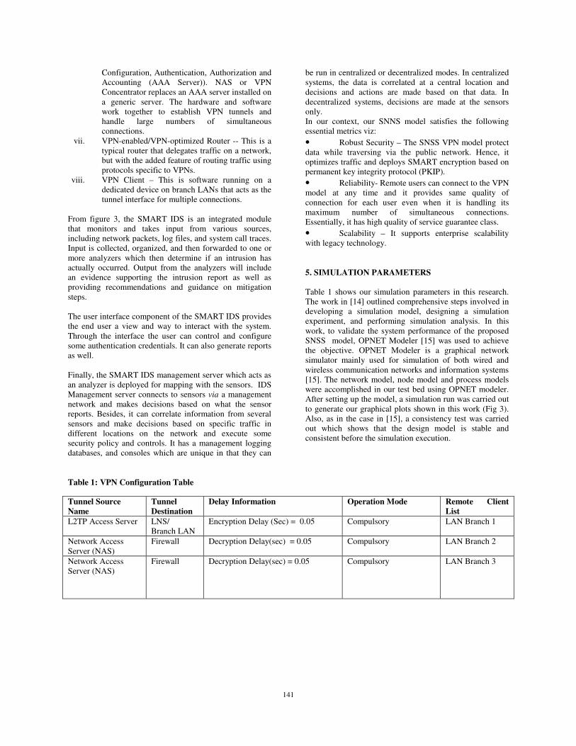
5. SIMULATION PARAMETERS
Table 1 shows our simulation parameters in this research.
The work in [14] outlined comprehensive steps involved in
developing a simulation model, designing a simulation
experiment, and performing simulation analysis. In this
work, to validate the system performance of the proposed
SNSS model, OPNET Modeler [15] was used to achieve
the objective. OPNET Modeler is a graphical network
simulator mainly used for simulation of both wired and
wireless communication networks and information systems
[15]. The network model, node model and process models
were accomplished in our test bed using OPNET modeler.
After setting up the model, a simulation run was carried out
to generate our graphical plots shown in this work (Fig 3).
Also, as in the case in [15], a consistency test was carried
out which shows that the design model is stable and
consistent before the simulation execution.
Table 1: VPN Configuration Table
Tunnel Source
Name
Tunnel
Destination
Delay Information Operation Mode Remote Client
List
L2TP Access Server LNS/
Branch LAN
Encryption Delay (Sec) = 0.05 Compulsory LAN Branch 1
Network Access
Server (NAS)
Firewall Decryption Delay(sec) = 0.05 Compulsory LAN Branch 2
Network Access
Server (NAS)
Firewall Decryption Delay(sec) = 0.05 Compulsory LAN Branch 3

142
6. SIMULATION RESULTS AND DISCUSSION
The results shown from figures 7 to figure 13 validates
performance improvement and stability of SNSS model.
Figure 5a depicts the network model developed in this
work. Also, figure 5b shows th SNSS initialiazation as
well.
Figure 5a: SNSS OPNET Network Model
The IP mapping, MPLS configurations and parameter
characterization were injected into the system
workload; however with our remote client list without
considering stochastic perturbations, the simulation
convergence presents a stable SNSS as shown in
figure 5b.
Table 2: SNMP/Logging Configuration Table
Parameters Values
Queue Length 10
Packet Size (MTU) 1500
Timeout 30secs
Source interface Outgoing
SNMP Reload Enabled
SNMP manger Enabled
Location Information Promoted
Contact Information Promoted
Nabled traps MPLS-Traffic Engineering
Console Login Debugging(7)
Internal buffer Size 4096
Logging Notification(5)
Link Port a L2TPNAS.PPP
Link Port b Internet.PPP
Table 2 shows a logging configuration table for our model.
The branch LAN sources have tunnel interfaces which
peridoically
Sends out 256kb data encrypted over the IP/MPLS backbone
while allowing the multilayer SMART IDS AP to monitor and
analyse the entire end to end devices. All packets have a
maxium translation unit (MTU) of 1500 bytes.
Figure 5b: SNSS OPNET initialization characterization
Fig. 6 shows the completed network simulation
representation used in OPNET for our experiments. Two
separate scenarios were used. The first is used for the VPN
experiment, and the second for the SNSS FTP session.
Both representations contained the same elements as shown
in our testbed in section IV; with the difference that the
former was created from custom process model to simulate
more accurately the exact characteristics of the VPN
testbed and the latter uses the standard and a custom tuned
version of VPN traffic flows.
Figure 6: SNSS Completed Simulation

143
Figs. 7 and 8 show higher throughput for the network testbed. Essentially, the end to architecture that allows IP/MPLS internet
backbone to tunnel data creates an efficient traffic flow via the tunnel interfaces. This justifies a reliable system model since the
link latency is very insignificant in our case.
Figure 7: SNSS branch LAN Node throughput behaviour
Figure 8: SNSS branch LAN throughput behavior

144
Figure 9: SNSS TCP Traffic behavior
The integration of SNSS VPN definitely affects the way the TCP services flow through the tunnels. The SMART IDS
(monitors) at the edge of the network (end to end) smartens http requests and acknowledgements by the remote active users.
Security implementation with our testbed infrastructure creates terminal tunnel confidence at different times as shown in fig. 9.
Hence, the proposed model in this work is envisaged to be very secure from any form of traffic. Also a number of security
parameters are affected whenever a change is made on the NAS server.
Figure 10: SNSS Site 2 site throughput behavior
145
From fig 10, to assess and justify the link throughput in
our model, we first used the Ethereal wireshack tool[16]
to analyze real packet flow policies in a typical site 2 site
VPN model as well as in some local production networks
in an area. In many cases, the ethereal protocol analyzer has
shown to be effective by discovering many packet conflicts
from a source to a destination that cannot discovered by
human visual inspection. We made an attempt to
quantitatively evaluate the practical consequences of
unverified packets from sources on the network throughput.
The Ethereal tool provides a wide range of network
statistics which ranges from general information about the
loaded capture file (like the number of captured packets), to
statistics about specific protocols (e.g. statistics about the
number of HTTP requests and responses captured). The
link throughput is the area analyzed from the global and
object palette of the OPNET simulator, which indicates the
receiving and sending of data packets. The utilized point to
point link at the simulated scenarios between the IDS APs,
NAS and management switch (MLS) (see figure 3) shows
the results of efficient link utilization. In this work, we
observed site 2 site throughputs can be as high as 100%
owing to bandwidth optimizing feature of the remote
gateways and device platforms.
REFERENCES
1. Whitepaper: Information Assurance Tools
Report”, Tools Sixth Edition September 25, 2009
2. H. Bourdoucen, A. Al Naamany and A. Al
Kalbani W: Impact of Implementing VPN to
Secure Wireless LAN”International Journal of
Computer and Information Engineering 3:1
2009,17.
3. N. Edde, Security Complete, Second Edition,
2002.
4. J. Pultz and N. Richard, Gartner Research (Cisco
White Paper): “Analysis of MPLS-Based IP VPN
Security: Comparison To Traditional L2VPNs
Such As ATM And Frame Relay, And
Deployment Guidelines” 1992–2004.
5. Sheila Frankel,Paul Hoffman Angela, Orebaugh
Richard Park,”Guide to SSL VPNs:
Recommendations of the National Institute of
Standards and Technology, July 2008
6. Frederick M. Avolio, “Security Review: SSL
VPNs” Online: [http://www.avolio.com]
7. Paul Ferguson,” What is a VPN” April 1998,
Revision 1 (unpublished)
8. Yudhvir Singh, Dr. Yogesh Chaba, Prabha Rani,
“Integrating – VPN and IDS – An approach to
Networks Security, (unpublished)
9. Ying-Dar Lin, Huan-Yunwei, and ShaoTangYu,
Building an Integrated Security Gateway:
Mechanisms performance Evaluations,
Implementations and Research Issues, EEE
communications Survey, the electronic Magazine
of original peer reviewed survey articles.
http://www.comsoc.org/pubs/surveys.
10. Ron Gula, Correlating IDS Alerts with
Vulnerability
Information, Tenable Network Security”
http://www.tenablesecurity.com, (December
2002).
11. G. Bianchi, “Performance Analysis of the IEEE
802.11 Distributed Coordination Function,” IEEE
Journal on Selected Areas in Communications,
Vol. 18, No. 3, pp. 535–547, Mar. 2000.
12. Wikhard M. Kiesel, Paul J. Kuehn, ‘A New
CSMA-CD Protocol for Local Area Networks
with Dynamic Priorities and Low Collision
Probability’ IEEE Journal on Selected Areas in
Communications, Vol. SAC-1, No.5, November
1983, p 869-876.
13. Akihiro Takagi, Shinichi Yamada, Shohei
Sugawara, ‘CSMA/CD with Deterministic
Contention Resolution’ IEEE Journal on
Selected Areas in Communications, Vol.
SAC-1, No.5, November 1983, p 877-884.
14. Prof. H. C. Inyiama, Udeze Chidiebele .C, Dr. C.
C. Okezie, Okafor Kennedy .C, MATLAB
SimEvent: A Process Model Approach to Event-
Based Communication Network Design (A Case
for Reengineered DCN), Journal of Basic and
Applied Scientific Research (JBASR), Volume 2
Number 5 (2012), pp 5070-5080.
15. C.-H. Ng, J. Chow, and Lj. Trajkovic,
“Performance evaluation of the TCP over WLAN
802.11 with the snoop performance enhancing
proxy,” OPNETWORK 2002, Washington, DC,
Aug. 2002.
16. Ethereal User's Guide: 18189 for Ethereal
0.10.14, 2004-2005
Author’s Profile
Okafor Kennedy C. is a Systems
Architect and R&D Consultant. He
holds B.Eng in Electrical
Electronics Engineering, (ESUT),
M.Eng in Digital Electronics and
Computer Engineering, (UNN)
while currently pursuing his PhD in
Electronics Engineering at
University of Nigeria Nsukka. He
works with Electronic Development Institute, Awka under
National Agency for Science and Engineering
Infrastructure, Nigeria as an R&D Engineer. He has various
vendor certifications including Cisco Certified Network
Associate, A+, etc. He is a member of NSE, IEEE, NCS,
and IAENG. His areas of interest include Network Design
& Cloud Management, Middleware Technologies, VLSI,
Enterprise-Wide Systems, Database Technologies,
Application Development, Security, WSN Technologies,
and Project Management. He can be reached through via E-
mail: [email protected].

146
Okezie Christiana .C is an associate
professor in Electronic and Computer
Engineering Department of Nnamdi
Azikiwe University Awka. She
received her B. Eng, from Anambra
State University of Technology
(ASUTECH), her M. Eng, and Ph.D
from Enugu State University of
Science and Technology, Enugu, Nigeria. She majors in
digital systems, e-governance, e-learning and control
engineering and has many publications to her credit.
Email- [email protected].
Udeze Chidiebele C. received his
B.Eng, M.Sc and PhD in Electronics
and Computer Engineering from
Nnamdi Azikwe University, Awka,
Nigeria. He holds his PhD in
computer and control systems
engineering. He is a Senior R & D
Engineer with Electronics
development Institute Awka, Nigeria. He works with
Electronic Development Institute, Awka under National
Agency for Science and Engineering Infrastructure, Nigeria
as an R&D Engineer. He is a member of Nigerian Society
of Engineers and has his COREN registration. His current
research interest is on DataCenter networks, Cloud
Computing and Applications, WSN Technologies, and
Control Systems Engineering. Email:
Okwuelu Nnaemeka got his B.Eng in
Electrical Electronics Engineering
from University of Agriculture,
Makurdi, Nigeria. He is a Research &
Development Engineer with
Electronics Development Institute
Awka, Nigeria. His current area of research interest is on
Electronic System Engineering and Power Electronics.
Phone Number: +2348037730844, Email: