Embed Size (px)
Citation preview
Journal of Engineering Science and Technology Vol. 7, No. 2 (2012) 156 - 168 © School of Engineering, Taylor’s University
156
SMALL-SCALE FILAMENT WINDING MACHINE FOR PRODUCING FIBER COMPOSITE PRODUCTS
SAAD MUTASHER*, NAZIM MIR-NASIRI, LEE CHAI LIN
School of Engineering and Sciences, Swinburne University of Technology
(Sarawak Campus) Jalan Simpang Tiga, 93350, Kuching, Sarawak, Malaysia
*Corresponding Author: [email protected]
Abstract
Over the years, filament winding has been recognized as a cost effective
technique to produce composite products with superior properties. In this paper,
small-scale automated filament winding machine was designed and fabricated. In
filament winding process, the fiber is impregnated with resin and wrapped on a
cylindrical shape mandrel. The designed machine integrates mechanical, electrical
and electronics components all controlled by a single PIC 18F452 micro-
controller. The paper presents series of algorithms that control the entire winding
processes. The machine generates helical winding patterns with various angles.
The winding patterns are achieved by controlling separately rotational speed of
mandrel and translational speed of carriage block on the lead screw. Testing of the
prototype shows that it is capable of producing winding angles in the range from
40 to 80 degrees. This machine can use for training the new students as a part
from their study of fabrication of long fiber composite materials.
Keywords: Winding machine, Composite material, Control systems, Helical winding.
1. Introduction
Composite fiber is recognized by the industry as an engineered material that is
capable to replace conventional material in producing durable and cost effective
products that are able to perform in adverse conditions. In general, composite
fiber winding machines are developed due to technological advances in various
industries including aerospace, marine, electrical, chemical, transportation, as
well piping system. The first filament winding machine was developed in 1950 in
accordance to the revolutions of filament winding applications [1]. The machines
had limited capabilities with the operating parts being gears, pulleys, belts, and
chain. Starting from 1990s, computer control systems were introduced to winding
Small-scale Filament Winding Machine for Producing Fiber Composite Products 157
Journal of Engineering Science and Technology April 2012, Vol. 7(2)
Nomenclatures
b Bandwidth of fiber, mm
degps Degree per step of stepper motor, deg.
K Spring stiffness, N mm/rad.
L Screw lead, mm/rev.
Nm Mandrel rotational speed, rpm
n Number of steps of stepper motor
P Number of turns
r Winding radius, mm
Greek Symbols
θ Winding angle, deg.
ω Motor speed, step-1
machine in order to form a control and servo system that can track position and
velocity with precise accuracy [2].
Modern filament winding machines are now operating under the control of
software such ad EasyWinder™, FiberGrafiX™, and CADWIND™ which are
capable to generate different pattern for winding purposes [3]. Still the cost of the
software as well as the cost heavy filament winding machines in the market is
quite high. In the filament winding process, winding machine is used to wrap
resin impregnated roving or monofilaments onto a rotating mandrel specimen
under controlled tension in a predetermined geometrical pattern. For this
purposes, a carriage is translating back and forth, positioning and laying the fiber
band onto the mandrel at an appropriate speed determined by the winding angle.
Fiber tension may be controlled by roller guides, comb or scissor bar. In the
industry, fiber materials that are commonly found are E-class, S- class, carbon,
glass and aramid type. For two degree of freedom filament winding machine, the
mandrels are usually cylindrical in shape. Resin formulation can be varied to
produce different mechanical, structural or electrical properties [4]. When the
resin cures, a solid outer casing with significant strength will be formed [1].
Properties of the finish composite products are dependent on the type of winding
pattern. Typical winding patterns are hoop winding, helical winding as well as
polar winding.
In this paper, a low cost small-scale automated composite fiber machine is
introduced with the capability to produce helical winding patterns, in the range
from 40o to 80
o winding angles. This is normally done by simultaneously
controlling rotary speed of the mandrel and linear speed of the carriage. In order
to simplify control algorithms in this design, mandrel’s speed is maintained at a
constant speed of 4.2 rpm. The speed of the carriage motor is varied according to
the desired winding angle. In addition, the tension gadget was designed to ensure
a uniform filament tension forces throughout the winding process, especially at
the edges of mandrel cylinders.
2. Mechanical and Electrical Setup of Winding Machine
The designed automated composite fiber winding machine is an integration of
mechanical, electrical, and electronics components. The machine is controlled by
158 S. Mutasher et al.
Journal of Engineering Science and Technology April 2012, Vol. 7(2)
PIC 18F452 microcontroller. This section discusses the details of designs of
mechanical, electrical and electronic subsystem.
2.1. Mechanical system design
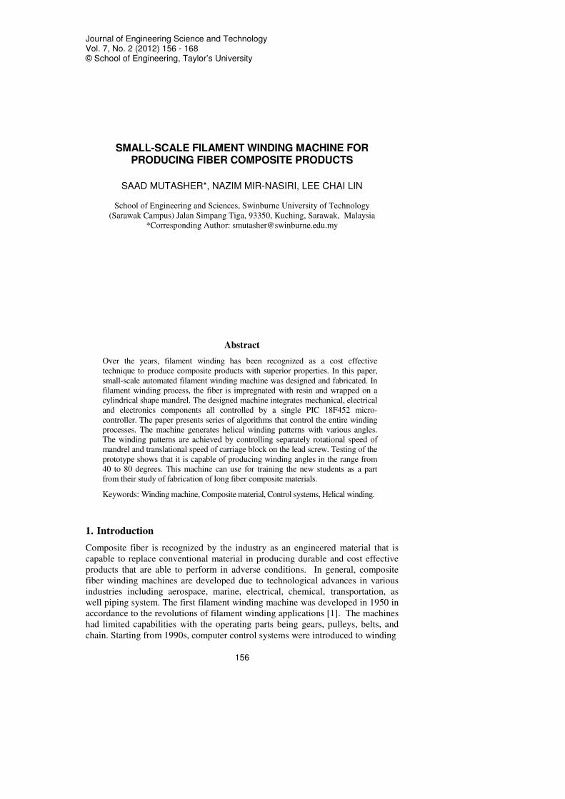
Computer-generated layout of the hardware configuration for automated
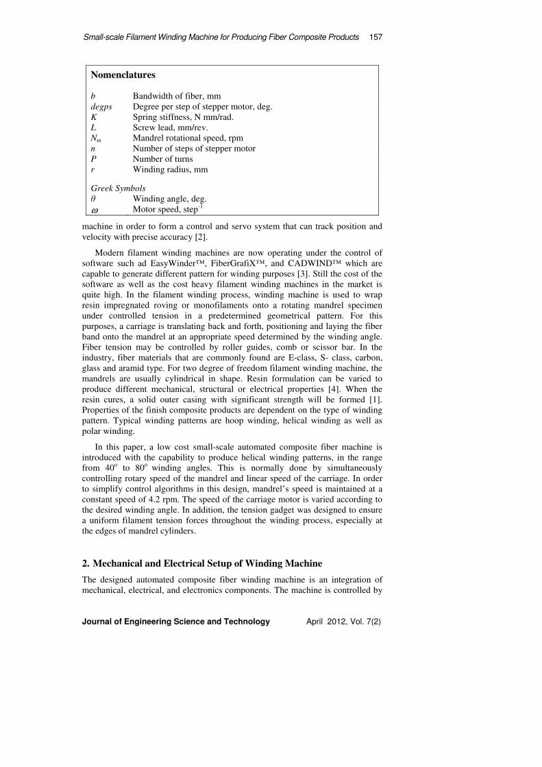
composite fiber filament-winding machine is shown in Fig. 1. Snap shot of the
actual machine is as shown in Fig. 2. In general, mechanical designs of the
machine can be categorized into two parts: delivery unit and rotary unit. Control
unit is an integral part of the machine.
The delivery unit is the most important module that consists of fiber holder,
tensional device, rollers guide, resin bath (with three rollers), carriage, lead screw,
lead screw holders and a stepper motor. Fiber holder is used to store fiber roving.
For the automated fiber winding machine, wet winding method is used. Hence, fiber
will pass through a resin bath before it is fed onto the mandrel through the carriage.
The carriage was made from low friction polymer. It consists of a roller and two
polished screw eyes which are used as a means to guide as well as to provide
tension to the wetted fiber before reaching the mandrel. Lead screw generates
rotary-to-linear motion transmission [5] after actuated by the stepper motor to move
the carriage linearly. Apart from that, the eyes are used to smear off excess resin
from the wetted fiber after passing through the rollers of the resin bath.
The resin bath was made from a steel container with three rollers and one eye.
In the winding process, resin bath is attached to the carriage in order to simplify
the tension controlling mechanism. Resin bath was used to store the polyester or
epoxy resin mixture. The eye was used as a way to guide the fiber to the resin
bath besides smearing off excess resin from the wetted fibers after going through
rollers of the resin bath.
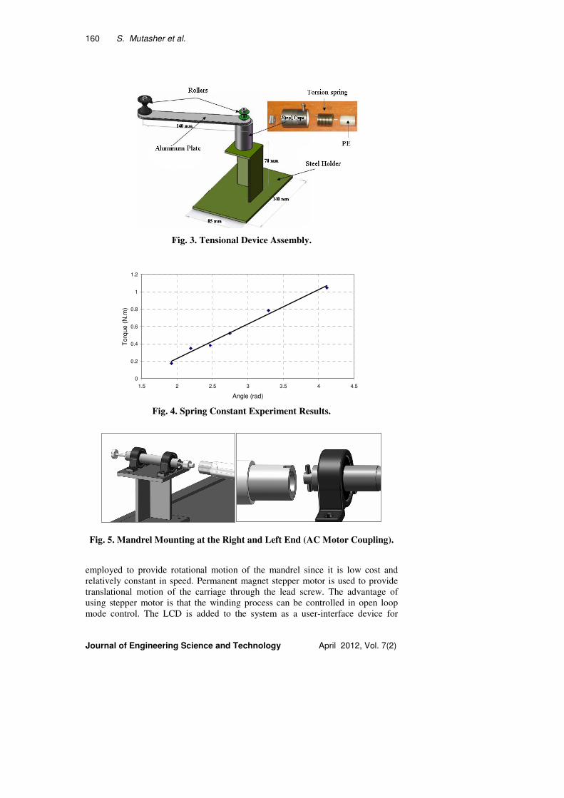
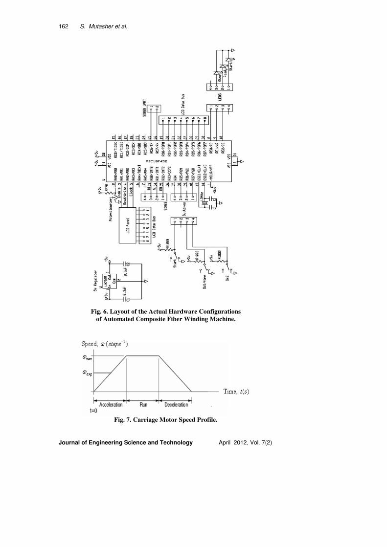
Tensional device as shown in Fig. 3 is used to generate constant tension force
in the fiber throughout the winding process. This tensional device was designed
with two rollers (to guide the fiber), steel holder, aluminum plate, steel cup and a
torsional spring. The spring constant K=0.3962 Nm/rad was found experimentally
as shown in Fig. 4.
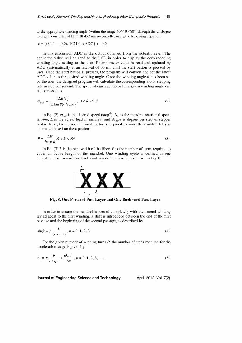
The rotary assembly unit consists of three pillar blocks which are held onto
the horizontal frame, a mandrel with rotating shaft and a small AC motor, as
shown in Fig. 5. All of the three pillar blocks are fixed in place. The shaft of the
mandrel is mounted onto the machine by pulling and pushing mechanism of the
PE shaft on the freely rotating shaft. At the other end of the mandrel, a steel shaft
is attached for AC motor coupling purposes.
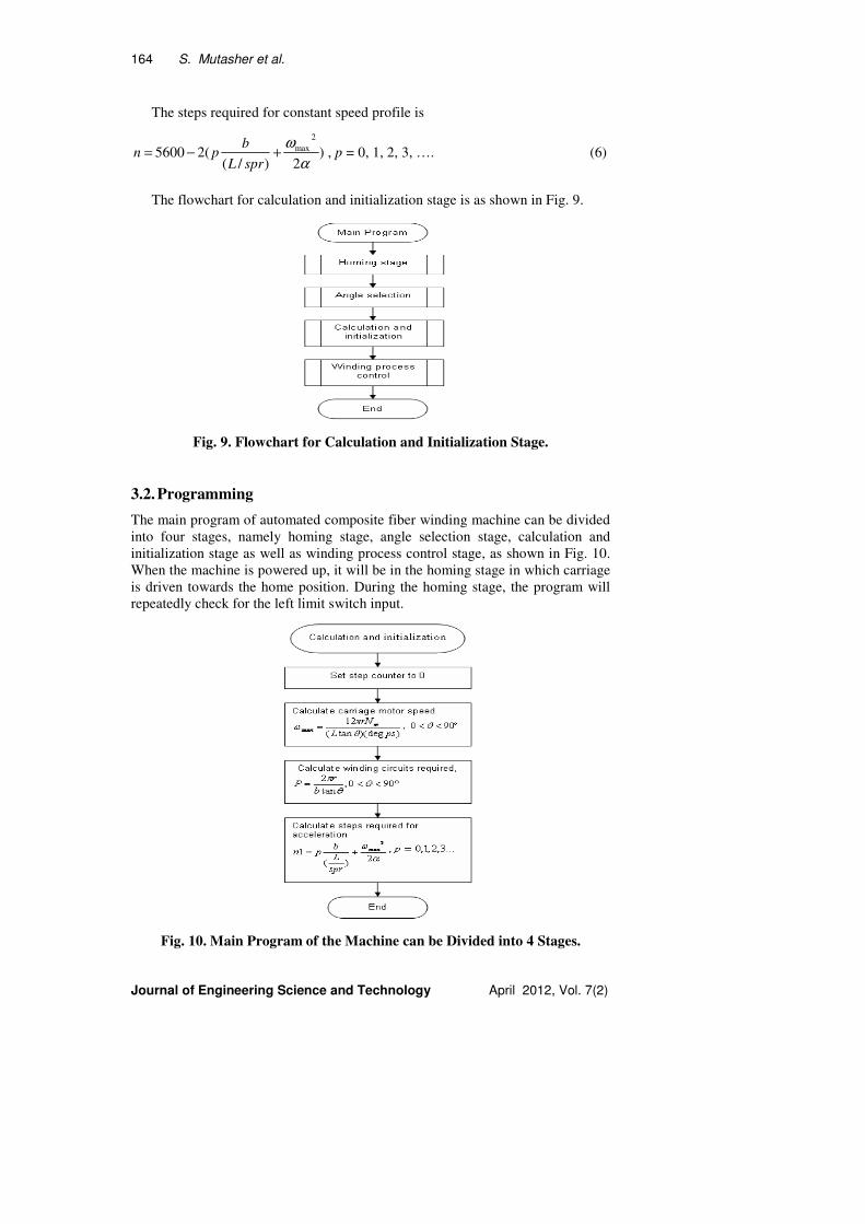
2.2. Electrical and electronic system design
Electronics system of the machine consists of a control box, an ac motor, a
permanent magnet stepper motor with driver, two limit switches and a power
supply. Control box houses the printed circuit board which is connected to the
control panel. Control panel consists of a LCD, a potentiometer, two push
buttons, three different colors LED pilot lights, and a power switch. Schematic
diagram of the overall circuit construction is as shown in Fig. 6. An AC motor is
Small-scale Filament Winding Machine for Producing Fiber Composite Products 159
Journal of Engineering Science and Technology April 2012, Vol. 7(2)
Fig. 1. Layout of the Hardware Configurations of Automated Composite
Fiber Machine and the Specifications of the Models and Test Conditions.
Fig. 2. Snapshot of the Composite Fiber Winding Machine.
160 S. Mutasher et al.
Journal of Engineering Science and Technology April 2012, Vol. 7(2)
Fig. 3. Tensional Device Assembly.
0
0.2
0.4
0.6
0.8
1
1.2
1.5 2 2.5 3 3.5 4 4.5
Angle (rad)
To
rqu
e (
N.m
)
Fig. 4. Spring Constant Experiment Results.
Fig. 5. Mandrel Mounting at the Right and Left End (AC Motor Coupling).
employed to provide rotational motion of the mandrel since it is low cost and
relatively constant in speed. Permanent magnet stepper motor is used to provide
translational motion of the carriage through the lead screw. The advantage of
using stepper motor is that the winding process can be controlled in open loop
mode control. The LCD is added to the system as a user-interface device for

Small-scale Filament Winding Machine for Producing Fiber Composite Products 161
Journal of Engineering Science and Technology April 2012, Vol. 7(2)
system monitoring. Three LED pilot lights are fixed on the panel of the control
box. Green light indicates the system is running. Red light shows the system is
halted or stopped. Amber light symbolizes the machine is ready for angle
selecting. The potentiometer is used as an interfacing device for user to input the
desired winding angle. This is to be accomplished by turning the potentiometer
knob. Analogue output from the potentiometer is connected to the ADC pin of the
microcontroller. Final conversion of the signal is in the range from 40 to 80
degree and it is displayed on the LCD panel. Apart from that, there are push
buttons to start and stop the machine respectively
3. System Control and Programming
3.1. Control method and algorithms
In terms of control, the main objective is to control speed of the mandrel and
carriage according to the known relationship [6]
θ
π
tan
2
L
NrN m
s = (1)
where r is the winding radius in mm, Nm is the mandrel’s rotational speed in
rpm, L is the screw lead in mm/rev and θ is the desired winding angle. For
simplicity, the mandrel speed is maintained constant and equal to 4.2 rpm during
the winding process. On the other hand, the speed of carriage is varied according
to the angle input from the user. The stepper motor is selected to drive carriage
due to its ability to be controlled in open loop mode with a sufficient accuracy.
Thus each winding turn can be controlled and shifted properly after the
appropriate motor rotary steps have been determined. In most cases, stepper
motors cannot instantly go from a stationary state directly to their maximum
speed due to the slip [7-8]. Rather, they must "ramp up" in speed to attain the
maximum speed. In order to accommodate this, the designed control algorithm
will speed up motor slowly, building up the drive current until it reaches the
required speed, as shown in Fig. 7. Let n1 are the required steps to accelerate the
motor from 0 to ωmax, n2 are the required steps to decelerate the motor from ωmax
to 0, and n are the total steps for constant speed. Due to the trapezoidal speed
profile, the steps required for the acceleration stage will be equal to the steps
required for the deceleration stage. The lead screw has pitch 6 mm/rev. It causes
the carriage to travel at 6mm per revolution. 48 steps of the stepper motor rotor
rotation are equal to one full revolution of the shaft. Hence, distance traveled per
step is (6/48) and this equal to 0.125 mm/step. Since the active winding length of
mandrel is set to 700 mm, bump switch is installed to control the carriage motion
only for 700 mm of length. The steps required for the carriage to travel along 700
mm distance is then equal
5600125.0
700==totn steps.
Since n1 = n2, then n = ntot - 2n1. The total steps required for constant speed
profile is, n = 5600 - 2n1.
The winding angle for the machine is set by the user. The user sets it through the
potentiometer control knob. The analogue value from the potentiometer is converted
162 S. Mutasher et al.
Journal of Engineering Science and Technology April 2012, Vol. 7(2)
Fig. 6. Layout of the Actual Hardware Configurations
of Automated Composite Fiber Winding Machine.
Fig. 7. Carriage Motor Speed Profile.
Small-scale Filament Winding Machine for Producing Fiber Composite Products 163
Journal of Engineering Science and Technology April 2012, Vol. 7(2)
to the appropriate winding angle (within the range 40o≤ θ ≤80
o) through the analogue
to digital converter of PIC 18F452 microcontroller using the following equation:
θ = {(80.0 – 40.0)/ 1024.0 × ADC} + 40.0
In this expression ADC is the output obtained from the potentiometer. The
converted value will be send to the LCD in order to display the corresponding
winding angle setting to the user. Potentiometer value is read and updated by
ADC systematically at an interval of 30 ms until the start button is pressed by
user. Once the start button is presses, the program will convert and set the latest
ADC value as the desired winding angle. Once the winding angle θ has been set
by the user, the designed program will calculate the corresponding motor stepping
rate in step per second. The speed of carriage motor for a given winding angle can
be expressed as
))(tan(
12max
psdegL
rNm
θ
πω = , °<< 900 θ (2)
In Eq. (2) ωmax is the desired speed (step-1
), Nm is the mandrel rotational speed
in rpm, L is the screw lead in mm/rev, and degps is degree per step of stepper
motor. Next, the number of winding turns required to wind the mandrel fully is
computed based on the equation
°<<= 900,tan
2θ
θ
π
b
rP (3)
In Eq. (3) b is the bandwidth of the fiber, P is the number of turns required to
cover all active length of the mandrel. One winding cycle is defined as one
complete pass forward and backward layer on a mandrel, as shown in Fig. 8.
Fig. 8. One Forward Pass Layer and One Backward Pass Layer.
In order to ensure the mandrel is wound completely with the second winding
lay adjacent to the first winding, a shift is introduced between the end of the first
passage and the beginning of the second passage, as described by
)/( sprL
bpshift = , p = 0, 1, 2, 3 (4)
For the given number of winding turns P, the number of steps required for the
acceleration stage is given by
α
ω
2/
2
max1 +=
sprL
bpn , p = 0, 1, 2, 3, . . . . (5)
164 S. Mutasher et al.
Journal of Engineering Science and Technology April 2012, Vol. 7(2)
The steps required for constant speed profile is
)2)/(
(25600
2
max
α
ω+−=
sprL
bpn , p = 0, 1, 2, 3, …. (6)
The flowchart for calculation and initialization stage is as shown in Fig. 9.
Fig. 9. Flowchart for Calculation and Initialization Stage.
3.2. Programming
The main program of automated composite fiber winding machine can be divided
into four stages, namely homing stage, angle selection stage, calculation and
initialization stage as well as winding process control stage, as shown in Fig. 10.
When the machine is powered up, it will be in the homing stage in which carriage
is driven towards the home position. During the homing stage, the program will
repeatedly check for the left limit switch input.
Fig. 10. Main Program of the Machine can be Divided into 4 Stages.
Small-scale Filament Winding Machine for Producing Fiber Composite Products 165
Journal of Engineering Science and Technology April 2012, Vol. 7(2)
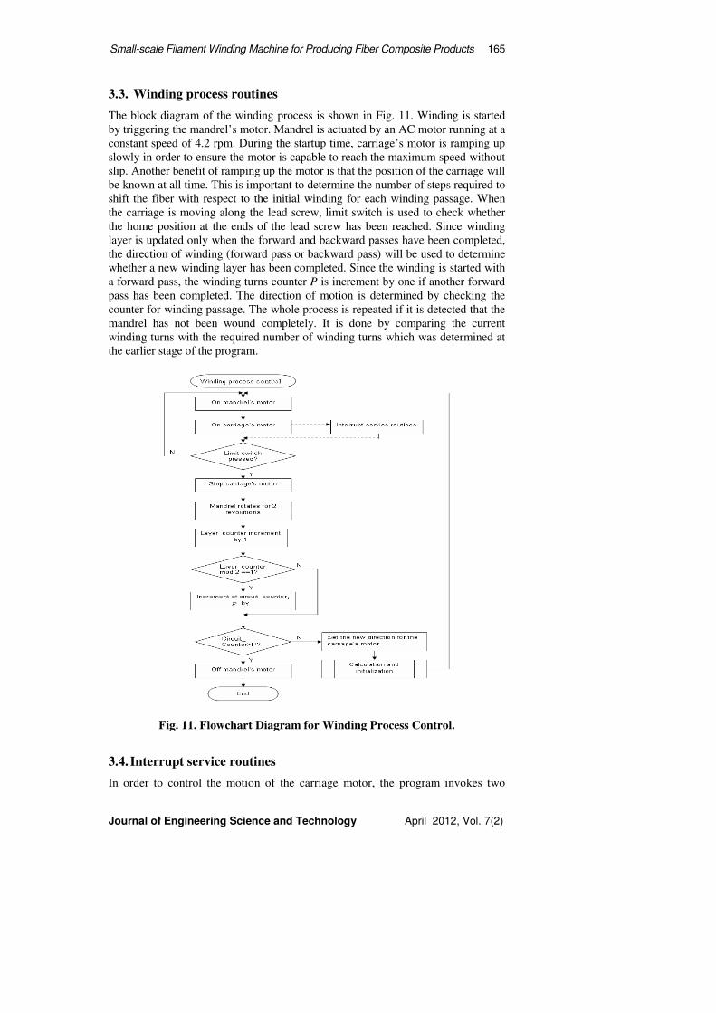
3.3. Winding process routines
The block diagram of the winding process is shown in Fig. 11. Winding is started
by triggering the mandrel’s motor. Mandrel is actuated by an AC motor running at a
constant speed of 4.2 rpm. During the startup time, carriage’s motor is ramping up
slowly in order to ensure the motor is capable to reach the maximum speed without
slip. Another benefit of ramping up the motor is that the position of the carriage will
be known at all time. This is important to determine the number of steps required to
shift the fiber with respect to the initial winding for each winding passage. When
the carriage is moving along the lead screw, limit switch is used to check whether
the home position at the ends of the lead screw has been reached. Since winding
layer is updated only when the forward and backward passes have been completed,
the direction of winding (forward pass or backward pass) will be used to determine
whether a new winding layer has been completed. Since the winding is started with
a forward pass, the winding turns counter P is increment by one if another forward
pass has been completed. The direction of motion is determined by checking the
counter for winding passage. The whole process is repeated if it is detected that the
mandrel has not been wound completely. It is done by comparing the current
winding turns with the required number of winding turns which was determined at
the earlier stage of the program.
Fig. 11. Flowchart Diagram for Winding Process Control.
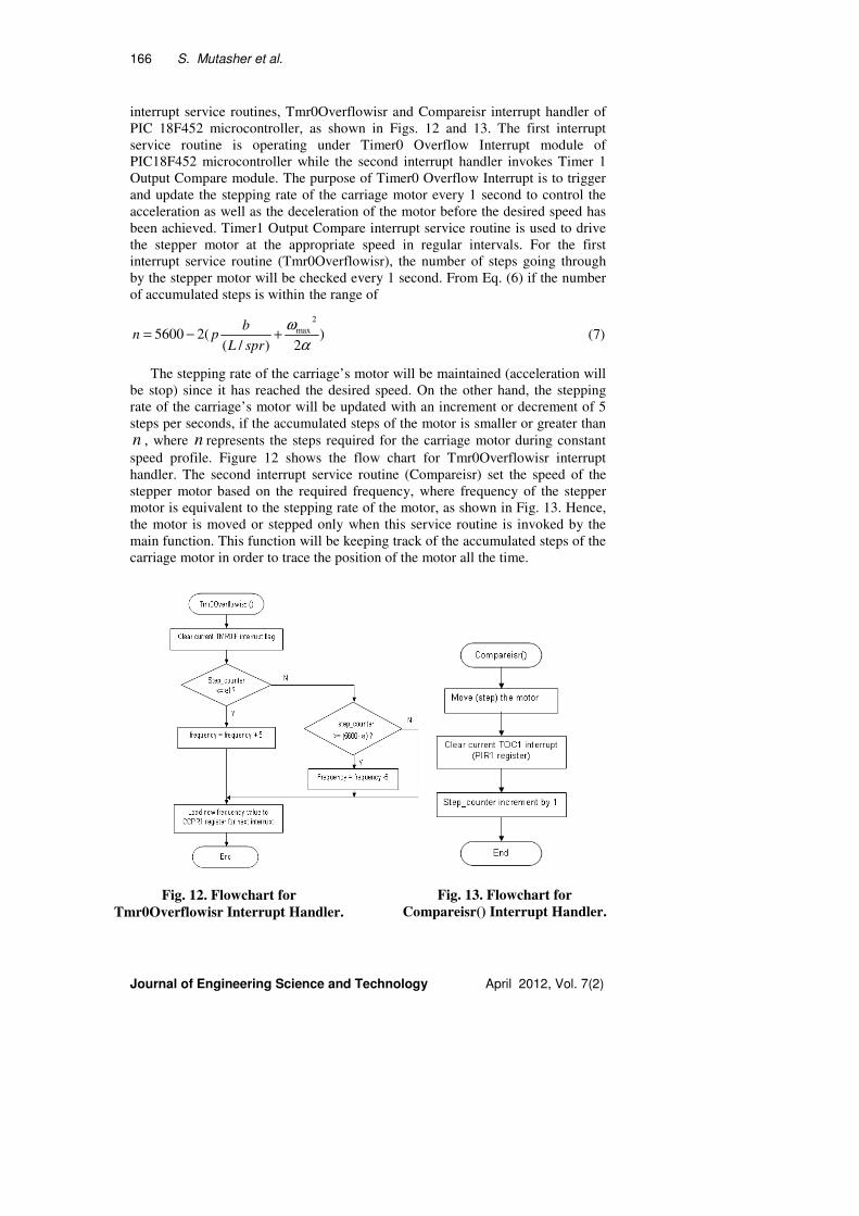
3.4. Interrupt service routines
In order to control the motion of the carriage motor, the program invokes two
166 S. Mutasher et al.
Journal of Engineering Science and Technology April 2012, Vol. 7(2)
interrupt service routines, Tmr0Overflowisr and Compareisr interrupt handler of
PIC 18F452 microcontroller, as shown in Figs. 12 and 13. The first interrupt
service routine is operating under Timer0 Overflow Interrupt module of
PIC18F452 microcontroller while the second interrupt handler invokes Timer 1
Output Compare module. The purpose of Timer0 Overflow Interrupt is to trigger
and update the stepping rate of the carriage motor every 1 second to control the
acceleration as well as the deceleration of the motor before the desired speed has
been achieved. Timer1 Output Compare interrupt service routine is used to drive
the stepper motor at the appropriate speed in regular intervals. For the first
interrupt service routine (Tmr0Overflowisr), the number of steps going through
by the stepper motor will be checked every 1 second. From Eq. (6) if the number
of accumulated steps is within the range of
)2)/(
(25600
2
max
α
ω+−=
sprL
bpn (7)
The stepping rate of the carriage’s motor will be maintained (acceleration will
be stop) since it has reached the desired speed. On the other hand, the stepping
rate of the carriage’s motor will be updated with an increment or decrement of 5
steps per seconds, if the accumulated steps of the motor is smaller or greater than
n , where n represents the steps required for the carriage motor during constant
speed profile. Figure 12 shows the flow chart for Tmr0Overflowisr interrupt
handler. The second interrupt service routine (Compareisr) set the speed of the
stepper motor based on the required frequency, where frequency of the stepper
motor is equivalent to the stepping rate of the motor, as shown in Fig. 13. Hence,
the motor is moved or stepped only when this service routine is invoked by the
main function. This function will be keeping track of the accumulated steps of the
carriage motor in order to trace the position of the motor all the time.
Fig. 12. Flowchart for
Tmr0Overflowisr Interrupt Handler. Fig. 13. Flowchart for
Compareisr() Interrupt Handler.
Small-scale Filament Winding Machine for Producing Fiber Composite Products 167
Journal of Engineering Science and Technology April 2012, Vol. 7(2)
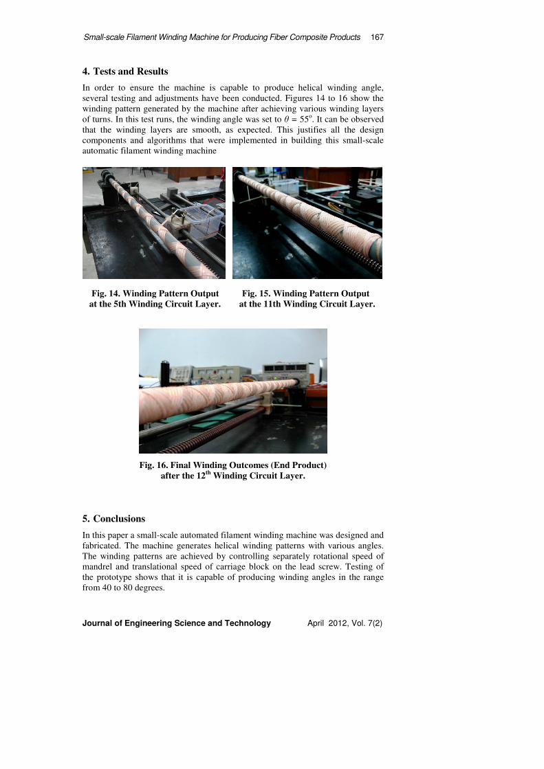
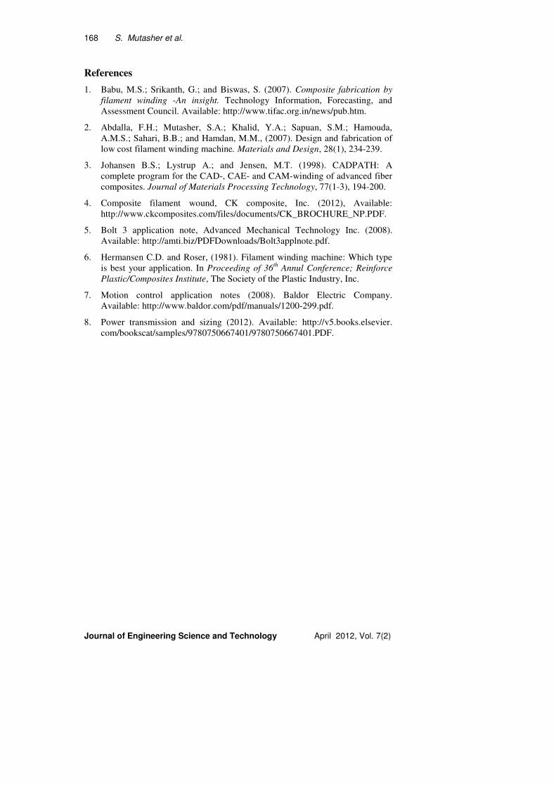
4. Tests and Results
In order to ensure the machine is capable to produce helical winding angle,
several testing and adjustments have been conducted. Figures 14 to 16 show the
winding pattern generated by the machine after achieving various winding layers
of turns. In this test runs, the winding angle was set to θ = 55o. It can be observed
that the winding layers are smooth, as expected. This justifies all the design
components and algorithms that were implemented in building this small-scale
automatic filament winding machine
Fig. 14. Winding Pattern Output Fig. 15. Winding Pattern Output
at the 5th Winding Circuit Layer. at the 11th Winding Circuit Layer.
Fig. 16. Final Winding Outcomes (End Product)
after the 12th
Winding Circuit Layer.
5. Conclusions
In this paper a small-scale automated filament winding machine was designed and
fabricated. The machine generates helical winding patterns with various angles.
The winding patterns are achieved by controlling separately rotational speed of
mandrel and translational speed of carriage block on the lead screw. Testing of
the prototype shows that it is capable of producing winding angles in the range
from 40 to 80 degrees.
168 S. Mutasher et al.
Journal of Engineering Science and Technology April 2012, Vol. 7(2)
References
1. Babu, M.S.; Srikanth, G.; and Biswas, S. (2007). Composite fabrication by
filament winding -An insight. Technology Information, Forecasting, and
Assessment Council. Available: http://www.tifac.org.in/news/pub.htm.
2. Abdalla, F.H.; Mutasher, S.A.; Khalid, Y.A.; Sapuan, S.M.; Hamouda,
A.M.S.; Sahari, B.B.; and Hamdan, M.M., (2007). Design and fabrication of
low cost filament winding machine. Materials and Design, 28(1), 234-239.
3. Johansen B.S.; Lystrup A.; and Jensen, M.T. (1998). CADPATH: A
complete program for the CAD-, CAE- and CAM-winding of advanced fiber
composites. Journal of Materials Processing Technology, 77(1-3), 194-200.
4. Composite filament wound, CK composite, Inc. (2012), Available:
http://www.ckcomposites.com/files/documents/CK_BROCHURE_NP.PDF.
5. Bolt 3 application note, Advanced Mechanical Technology Inc. (2008).
Available: http://amti.biz/PDFDownloads/Bolt3applnote.pdf.
6. Hermansen C.D. and Roser, (1981). Filament winding machine: Which type
is best your application. In Proceeding of 36th Annul Conference; Reinforce
Plastic/Composites Institute, The Society of the Plastic Industry, Inc.
7. Motion control application notes (2008). Baldor Electric Company.
Available: http://www.baldor.com/pdf/manuals/1200-299.pdf.
8. Power transmission and sizing (2012). Available: http://v5.books.elsevier.
com/bookscat/samples/9780750667401/9780750667401.PDF.