Embed Size (px)
Citation preview
SMALL SATELLITE APPLICATIONS OF COMMERCIAL OFF THE SHELF
RADIO FREQUENCY INTEGRATED CIRCUITS
A Thesis
by
JOHN THOMAS GRAVES
Submitted to the Office of Graduate Studies of Texas A&M University
in partial fulfillment of the requirements for the degree of
MASTER OF SCIENCE
December 2011
Major Subject: Aerospace Engineering

Small Satellite Applications of Commercial Off the Shelf Radio Frequency Integrated Circuits
Copyright 2011 John Thomas Graves
SMALL SATELLITE APPLICATIONS OF COMMERCIAL OFF THE SHELF
RADIO FREQUENCY INTEGRATED CIRCUITS
A Thesis
by
JOHN THOMAS GRAVES
Submitted to the Office of Graduate Studies of Texas A&M University
in partial fulfillment of the requirements for the degree of
MASTER OF SCIENCE
Approved by:
Chair of Committee, Helen Reed Committee Members, Alan Palazzolo Ana Goulart Head of Department, Dimitris Lagoudas
December 2011
Major Subject: Aerospace Engineering
iii
ABSTRACT
Small Satellite Applications of Commercial Off the Shelf Radio Frequency Integrated Circuits.
(December 2011)
John Thomas Graves, B.S. Aerospace Engineering, Texas A&M University
Chair of Advisory Committee: Dr. Helen Reed
Within the first decade of the 21st century, the aerospace community has seen many more
opportunities to launch small spacecraft in the 10 to 100 kg mass class. Coupled with this has been
consistent interest from the government in developing small-spacecraft platforms to expand civil and
military mission possibilities. Small spacecraft have also given small organizations such as universities an
increased access to space.
Because small satellites are limited in size, power, and mass, new and often nontraditional capabilities
must be explored and developed to make them viable and attractive when compared with larger and more
proven spacecraft. Moreover, small organizations that wish to contribute technically are often limited by
the small size of their teams and available resources, and need creative solutions for meeting mission
requirements.
A key need is in space-to-ground communications. Complex missions typically require large amounts
of data transfer to the ground and in a timely fashion. Available options trade hardware cost, available
ground stations or networks, available operating-frequency range, data-rate performance, and ease of use.
A system for small spacecraft will be presented based upon Radio Frequency Integrated Circuits
(RFIC) that minimizes development effort and maximizes interface control to meet typical small-
spacecraft communications requirements. RFICs are low-cost components that feature pre-built radio
hardware on a chip that can be expanded easily by developers with little or no radio experience. These
devices are widespread in domestic applications for short-range connectivity.

iv
A preliminary design and prototype is presented that meets basic spaceflight requirements, offers data
rates in the 55 to 85 kbps range, and has completed basic proof-of-concept testing. While there are higher-
data-rate alternatives in existence, the solution presented here strikes a useful balance among data rate,
parts cost, and ease of use for non experts, and gives the user operational control necessary to make air-to-
ground communications time effective.

v
DEDICATION
To my parents for getting me to this point and to my wife who supported me through it all

vi
ACKNOWLEDGEMENTS
I would like to thank the services and advice of my committee members Dr. Palazzolo and Dr.
Goulart throughout the thesis development and defense process.
I owe a great deal to Colleen Leatherman and Karen Knabe for support from within the Aerospace
Department to navigate all matters of business and administration during this thesis process. They have
always brought common sense, effort, and clever solutions to any difficulty I have had in the process.
All engineering and practical matters relating to this thesis development could not have been
completed without the help of Joseph Perez, who brought years of experience working on spacecraft of all
shapes and sizes to bear. His mentorship taught me how to leap from paper development and into real
hardware. I doubt very much I could have made any of my efforts and plans functional without his
tutelage and focus on discipline, careful and deliberate methodology when working in the laboratory, and
extensive advice on any practical matters I happened to be unfamiliar with.
Finally, and most importantly, I would like to thank my committee chair, graduate advisor, colleague,
and friend, Dr. Helen Reed. She has been the prime force behind my work since I was a sophomore
working on my Bachelor’s degree. She came to Texas A&M in 2004, with a desire to establish a student
satellite laboratory based upon her successful work at Arizona State University. I met her in December of
2004 asking how I could be involved, and she was able to take my interest at the time, and transform it
into an amazing set of experiences, work, learning, and partnerships. During this time I have been allowed
to contribute to help put Texas A&M at the forefront of space engineering through its own indigenous
spacecraft programs, grow as a leader, take on a graduate education, and add amazing depth and
dimension to my experiences at Texas A&M.
She is a tireless champion and supporter of her student’s dreams and ideas, and none of what I have
accomplished would have been possible without her.
vii
TABLE OF CONTENTS
Page
ABSTRACT ........................................................................................................................................ iii
DEDICATION .................................................................................................................................... v
ACKNOWLEDGEMENTS ................................................................................................................ vi
TABLE OF CONTENTS .................................................................................................................... vii
LIST OF FIGURES ............................................................................................................................. ix
LIST OF TABLES .............................................................................................................................. xi
I. INTRODUCTION ....................................................................................................................... 1
A. University Programs ................................................................................................... 2 B. AggieSat Lab .............................................................................................................. 2 C. The Goal: Improvement in Communications Subsystems ......................................... 4 D. Current Alternatives ................................................................................................... 5 E. The Proposed Solution: Radio Frequency Integrated Circuits ................................... 7
II. EXISTING SYSTEMS AND ALTERNATIVES ........................................................................ 10
A. Amateur Radio Systems ............................................................................................. 14 B. Custom Systems ......................................................................................................... 15 C. Commercial Wireless Modem Systems ..................................................................... 20 D. The RFIC Thesis Project ............................................................................................ 25
III. SYSTEM OBJECTIVES AND REQUIREMENTS DEFINITION ............................................. 26
A. System Objectives ...................................................................................................... 26 B. System Requirements ................................................................................................. 28 IV. SYSTEM CONCEPT DEFINITION ........................................................................................... 30
A. RFIC Device Trade Space and Selection ................................................................... 30 B. The Texas Instruments CC1101 Radio Frequency Integrated Circuit ........................ 34 C. System Concept .......................................................................................................... 37 D. Microcontroller Selection ........................................................................................... 44
V. PRELIMINARY DESIGN DESCRIPTION ................................................................................ 47
A. Hardware Design ........................................................................................................ 47 B. Software Design ......................................................................................................... 49 C. Development Summary .............................................................................................. 53
viii
Page
VI. VERIFICATION PLAN .............................................................................................................. 57
A. Link Budget Description ............................................................................................ 59 B. Data Rate Budget Description .................................................................................... 59 C. Frequency Error Analysis Description ....................................................................... 59 D. Basic Functional Testing Description ........................................................................ 60
E. Oscilloscope Testing Description ............................................................................... 60 F. Packet Loss Rate Testing Description ........................................................................ 61 G. Phase 3 Testing Description ....................................................................................... 65
VII. VERIFICATION ANALYSIS ..................................................................................................... 66
A. Link Analysis ............................................................................................................. 66 B. Data Rate Analysis ..................................................................................................... 72 C. Frequency Error Analysis........................................................................................... 77 VIII. OSCILLOSCOPE TESTING RESULTS ................................................................................... 83
A. Scope of Results ......................................................................................................... 83 B. Signal Structure Measurement ................................................................................... 84 C. Looped Packet Structure Measurement ...................................................................... 86 D. Summary .................................................................................................................... 90 IX. PACKET LOSS RATE TESTING RESULTS ............................................................................ 92
A. Scope of Results ......................................................................................................... 92 B. Noise Power Issues .................................................................................................... 93 C. Signal Level Test Results ........................................................................................... 94 D. Data Rate Calculation ................................................................................................ 99
E. Offset Test Results ..................................................................................................... 100 F. Summary .................................................................................................................... 103
X. PROXIMITY OPERATIONS ...................................................................................................... 105
XI. MINIMUM SHIFT KEYING VERSUS FREQUENCY SHIFT KEYING ................................. 107
XII. CONCLUSION ............................................................................................................................ 110
A. Requirements Evaluation ........................................................................................... 111 B. Verification Plan and Future Work ............................................................................ 115 C. Lessons Learned ......................................................................................................... 116 D. Final Evaluation ......................................................................................................... 117
REFERENCES .................................................................................................................................... 119
APPENDIX A ..................................................................................................................................... 132
APPENDIX B ..................................................................................................................................... 137
VITA .................................................................................................................................................. 141
ix
LIST OF FIGURES
. Page Figure 1 Typical RFIC chip examples ............................................................................................ 8 Figure 2 Major functional blocks and interfaces of the CC1101 RFIC transceiver [111] .............. 35 Figure 3 High data rate downlink system concept. ......................................................................... 38 Figure 4 Baseline proximity operations configuration. .................................................................. 41 Figure 5 CC1101EMK module....................................................................................................... 47 Figure 6 RFIC control unit board ................................................................................................... 48 Figure 7 RFIC control unit TX state machine ................................................................................ 50 Figure 8 RFIC control unit RX state machine. ............................................................................... 51 Figure 9 RFIC control unit TX breadboard with CC1101EMK ..................................................... 54 Figure 10 Work in progress RFIC breadboard receiver (foreground) and RFIC breadboard transmitter (background). .................................................................................................. 55 Figure 11 Completed preliminary design RFIC unit ........................................................................ 56 Figure 12 Basic oscilloscope testing arrangement ............................................................................ 61 Figure 13 Packet Loss Rate (PLR) testing arrangement ................................................................... 62 Figure 14 Packet Loss Rate (PLR) testing arrangement implementation ......................................... 63 Figure 15 RFIC unit with aluminum box for PLR test. .................................................................... 63 Figure 16 Concept of closed loop downlink data operations. ........................................................... 74 Figure 17 Satellite relative velocity geometry .................................................................................. 81 Figure 18 End to end packet transmission cycle from start of transmitter USART operations to the end of receiver USART operations.............................................................................. 84 Figure 19 End to end packet transmission cycle from start of transmitter interrupt operations to the end of receiver interrupt operations. ............................................................................ 85 Figure 20 Packet loop timing structures for long range and short range cases ................................. 86 Figure 21 LabVIEW packet loop timing structures .......................................................................... 89 Figure 22 Docklight packet loop timing structures for the long range case ..................................... 90

x
. Page Figure 23 Docklight packet loop timing structures for the short range case. .................................... 90 Figure 24 Packet loss rates over expected signal level ranges with the original LabVIEW based test system ........................................................................................................................ 95 Figure 25 Packet loss rates over expected signal level ranges with the Docklight system compared to the original LabVIEW based test system ...................................................................... 96 Figure 26 Packet loss rates over expected signal level ranges with the Docklight system compared to the original LabVIEW based test system and new focused LabVIEW results run after the first test period ............................................................................................................. 97 Figure 27 Packet loss rates over expected signal level ranges with the Docklight system short delay compared to the Docklight system with the long transit delay. ............................... 98 Figure 28 RFIC transmitter signal output shown on the spectrum analyzer at a signal level of -92.39 dBm ........................................................................................................................ 101 Figure 29 RFIC transmitter offset packet loss rate results at approximately -92 dBm signal power .............................................................................................................................. 102 Figure 30 Spectrum analyzer output of a CC1101 using FSK modulation ...................................... 108 Figure 31 Spectrum analyzer output of a CC1101 using MSK modulation ..................................... 109
xi
LIST OF TABLES
Page
Table 1 University class and research organization missions since 2009 ..................................... 13
Table 2 RFIC project system requirements ................................................................................... 29
Table 3 Modulation scheme definitions ........................................................................................ 31
Table 4 Candidate RFIC devices ................................................................................................... 32
Table 5 High data rate downlink configuration space segment conceptual specifications ............ 39
Table 6 High data rate downlink configuration conceptual link budget ....................................... 40
Table 7 Baseline proximity operations configuration space segment conceptual specifications .. 42
Table 8 Proximity operations configuration conceptual link budget ............................................. 43
Table 9 Preliminary design RFIC control unit command listing ................................................... 52
Table 10 Summary of preliminary verification plan ....................................................................... 58
Table 11 Estimated received carrier power for 4 Watts transmitter power ..................................... 68 Table 12 Noise figure estimates for the receiver system ................................................................. 69
Table 13 Noise figure estimates from SMAD and DOC models .................................................... 70 Table 14 Estimated FSK noise power for various noise models with estimated system noise added ................................................................................................................................ 71
Table 15 Estimated FSK signal to noise natio and margin at 10 degrees elevation for a 350 km orbit .................................................................................................................................. 72
Table 16 RFIC system service and process speeds ......................................................................... 75
Table 17 Estimated payload data rates ............................................................................................ 77

1
I. INTRODUCTION
The aerospace community at large has a high interest in developing small-spacecraft platforms to
expand civil and military mission possibilities. Per the definitions of Sweeting [1], micro-satellites and
nano-satellites have masses less than 100 kg and 10 kg, respectively. A study by Futron Corporation [2] on
behalf of AFRL in 2008 identified six major markets ranging from military technology development to
Earth observation that could feature high demand of small spacecraft. This report also pointed to new
funding for small satellite technology development that had been included as a line item in NASA’s 2011
budget. This work went on to report that a 100 to 200 kg spacecraft in the range of $5-10 million cost,
with up to two years lifetime would fit the bill for the demand categories.
Bille et al. [3] also indicates strong interest in small spacecraft innovation and development by large
agencies other than NASA, including the Defense Advanced Research Projects Agency (DARPA) and The
National Reconnaissance Office (NRO), all who continued to invest in small spacecraft during 2011.
Likewise, since 1981, many small spacecraft have been developed by students at universities to
promote engineering education. These satellites have also carried payloads in general technology research
and science investigations, but have been primarily concerned with training the future workforce [4].
Small satellites are limited in size, power, and mass, and new and often nontraditional capabilities
must be explored and developed to make them viable and attractive when compared with larger and more
proven spacecraft. Limited budgets are well established as a trend in modern aerospace engineering
projects and there can be benefits to small replaceable systems [5]. In some cases small size can directly
translate into reduced hardware cost and launch mass. It can also translate into fundamental changes in the
way spacecraft systems are developed and operated. Smaller spacecraft not only promise benefits of cost
and alternative styles of mission development and execution, but have also given small organizations such
as university developers increased access to space.
____________ This thesis follows the style of the AIAA Journal of Spacecraft and Rockets
2
These systems have enjoyed continued development and miniaturization for the past 20 years [3], and
further improvements are being vigorously pursued by the community to capitalize on the benefits. As
Bille et al. points out, the key question is one of application. What is the best use of the small platforms
[3]? How then can these uses be expanded or improved?
A. University Programs
Swartwout’s listing of spacecraft missions indicates a significant increase in the flight rates of
spacecraft at the university level in the past decade [4]. Most recent university-level launch opportunities
have featured clutches of “CubeSats” based on the 4” standard pioneered by Stanford and California
Polytechnic State University [6, 4, 5]. More capable 10-100kg satellites have been flown. These missions,
such as ASUSat1, Three Corner Sat, and FASTRAC, have more ambitious mission goals, but have been
flown in far fewer numbers [7, 8, 9, 4].
Capability needs to be expanded within all of these spacecraft platforms at the university level to
enable more effective contributions in science and engineering. It has been argued by Swartwout [10] that
in spite of the number of small spacecraft flown, very little innovation has been demonstrated and these
missions are serving educational needs above all others. Small organizations such as universities that wish
to contribute technically are often limited by the small size of their teams and available resources.
Hunyadi, et al. [11] argue that the constraints imposed by small spacecraft foster innovation by their
very nature and that the end goal for university programs could be to exercise freedom to develop
nontraditional solutions. Creative low-cost solutions supporting mission requirements would be most
welcome contributions to the community.
B. AggieSat Lab
AggieSat Lab was founded at Texas A&M University (TAMU) in 2005 by Dr. Helen Reed to
“demonstrate and develop modern technologies by utilizing small-satellite platforms while educating
students and enriching the undergraduate experience” [12].

3
While educational impact is core to AggieSat Lab and a very important part of university small
satellite missions, AggieSat Lab also wishes to advance the state of the art in spacecraft design.
Dr. Reed brought the satellite laboratory to Texas A&M from Arizona State University (ASU). At
ASU, the ASUSat1 and Three Corner Satellite (3CS) spacecraft were completed and flown by students
[12].
Currently AggieSat Lab is pursuing a four mission campaign called LONESTAR with NASA Johnson
Space Center (JSC) and the University of Texas at Austin (UT) to develop novel solutions for
Autonomous Rendezvous and Docking (ARD). The lab designed, developed, and flew the AggieSat2
spacecraft in 2009 onboard Space Shuttle Endeavour on the STS-127 mission. This was the lab’s first
flight experience and the first phase of the LONESTAR campaign.
AggieSat2 was operational for 230 days before re-entering the Earth’s atmosphere in March of 2010.
This mission carried a Global Positioning System (GPS) receiver developed by NASA for space
navigation. Since then AggieSat Lab has continued with the JSC campaign and other parallel projects in
partnership with both government and commercial partners. [13]
The proposed size and cost of spacecraft defined by the Futron corporation study is similar to the
spacecraft class proposed for subsequent missions in the AggieSat Lab LONESTAR campaign. AggieSat
has been working on an expandable bus of 50-100kg in size to support and enable university class research
including missions beyond the ARD campaign [14].
The Lab has recognized a key development area in space-to-ground communications. Complex
missions typically require large amounts of data transfer to the ground and in a timely fashion. Data rate,
control of the system, and robustness of the communications link need to be increased so that large
amounts of data can be downloaded from small spacecraft quickly and reliably.
As will be explored, the capability of small organizations to provide high-speed and reliable
communications has been limited in the past. A low-cost alternative that would allow university
organizations to balance implementation control and performance is desired. An alternative of this nature
would allow more data to flow from space to ground. This would in turn allow more utility to be obtained
4
from other enhanced subsystems and payloads, thus increasing general capabilities without increasing
overall mass.
C. The Goal: Improvement in Communications Subsystems
The current majority of operational small satellite missions use communication data rates below
19,200 bps [6]. As of 2003 approximately 70% of digital amateur satellite operators (ham radio
community specifically) operated at 9,600 bps and the rest operated at 1,200 bps [15]. A quick survey of
non-amateur radio community university class spacecraft since 2000 (including the CubeSats, Arizona
State’s ASUSat1 and 3CS, the United States Naval Academy RAFT mission, and University of Texas’
FASTRAC) shows repeated use of amateur type data rates, frequency bands, and radios suggesting that
this type of accessible, off the shelf equipment is still dominating university satellite communications
systems [16, 6, 7, 8, 9]. The field appears stagnant considering that the first amateur 9,600 bps packet
capable small satellite, Orbiting Satellite Carrying Amateur Radio (OSCAR) UO-14, was launched in
1990 [15].
While these amateur radio speeds may be sufficient for requirements of the aforementioned missions,
they do very little towards expanding future small spacecraft capabilities. A good example of this comes
from the projected mission data download needs for AggieSat4, now under development at AggieSat Lab.
AggieSat4 is intended to fulfill the second flight in the LONESTAR ARD campaign. AggieSat4 will
be conducting relative GPS navigation measurements between itself and a University of Texas partner
spacecraft, taking photographs of the partner spacecraft separation, and handling basic engineering health
and attitude control information during the course of the flight. A modest mission success data load of 24
hours of attitude control data post launch vehicle deployment, 30 1024x768 images of partner satellite
separation, 3 orbits of relative GPS data, and partner separation attitude control data is estimated to be
about 600 Megabits (see Appendix A).
At 9,600 bps, with AggieSat Lab’s ground station assumptions, this could take up to 7 months! If the
currently planned, but untested, high data rate radio for AggieSat4 is flown at 38,400 bps the time to
download drops to 1.5 months. If the same volume of data could be downloaded through a system in the

5
range of 50,000 to 150,000 bps the same payload could be brought down in 2-4 weeks! Even modest gains
in robustness, download rate, or both can have significant impact on the speed at which mission success
could be achieved.
D. Current Alternatives
A limited number of missions have used large ground segments furnished by commercial partners or
the government to assist in mission completion. This includes the GeneSat-1 mission flown by Santa Clara
University which used an 18 meter dish leased from SRI International to close their link budget, and the
Naval Academy RAFT mission which used Department of Defense assets to provide a wide area of
coverage for a RADAR experiment [17, 16]. These capabilities are unique among small satellite programs.
The government itself has very mature and capable ground and space networks for civil and defense
related spacecraft [18, 19, 20], but these have proven unavailable because of high demand. Even with
NASA partners, AggieSat Lab has been unable to leverage assets such as the NASA’s ground based S-
Band system or the space borne Tracking and Data Relay Satellite System (TDRSS) for the up and coming
ARD campaign flights.
Wireless Local Area Network (WLAN) utility modems such as those offered by Microhard Systems
and Digi International have been popular solutions for recent mission because they promise to offer data
rates approaching 230,000 bps [21, 22]. This option was first popularized by Santa Clara University and
the GeneSat-1 mission which used these modems in conjunction with a large ground segment, and has
since been promoted by included standard interfaces for these modems among the 4” CubeSat community
[23, 17].
AggieSat2 attempted to use the MHX-425 variant of the Microhard products during its flight in 2009
and 2010. These radio types are built to ground based network requirements and are Frequency Hopping
Spread Spectrum (FHSS), meaning they statistically jump from frequency to frequency to maximize
bandwidth to many users. This prevents conventional channel tuning and sets up many problems for space
based operations relating to frequency control and Doppler shift. Because of this, AggieSat2 did not have

6
robust radio control during its flight. It is thought that this contributed to significant communications
problems that were experienced during the flight. [13]
Modems of this type are “black box” solutions and the protocols and logic which govern the spread
spectrum control are not public domain. AggieSat was not able to get support to modify this type of radio
to address space related control needs from the manufacturer. From a business perspective this is
understandable because requests from small spacecraft projects are usually low volume, but it prevents
these radios from being adequately controlled, documented, and understood for space engineering
purposes.
Defense contractors such as L-3 communications offer high performance military class systems [24].
Other developers such as Comtech AeroAstro and Surrey are offering smaller systems compatible with the
NASA and government networks that have rates in the Megabit range [25, 26]. These solutions are very
attractive and would make a discussion about 50,000 to 150,000 bps moot.
It still should be considered that these systems must be weighed against cost. The contractor options
are low volume, space qualified products that can challenge the resource capability of university programs.
AggieSat often finds it hard to obtain quotes or basic information on such systems.
Regardless of any other developments, the space qualified offerings from major manufacturers will
always be available to those with resources.
Near term developments that add value to the small spacecraft community will come from alternatives
built from more fundamental elements that can be configured within the small organizations themselves,
while still offering performance improvements over the low end radio systems.
An alternative system like this would be a fantastic cost saving proposition for missions like
AggieSat4 which struggle with the performance offered by traditional amateur systems, but do not have
budgets of the same order of magnitude as NASA and military small science and research missions.
A further question to consider is whether or not a more fundamental development can be initiated
without having to design and build a complete radio system from scratch. This opposite extreme requires
an extensive set of tools and Radio Frequency (RF) expertise beyond that of most undergraduate
7
engineers. If a program is not careful the resulting cost of test equipment and resources to perform detailed
radio work can be equally prohibitive.
E. The Proposed Solution: Radio Frequency Integrated Circuits
A way to add design control to the system and potentially limit the development overhead would be to
use one of the wide varieties of RFICs available from manufacturers today. These chips are compact
integrated circuits (IC) that feature combined data interface, RF oscillator, mixing, and amplification
circuits. RFIC radio hardware is typically used in cell phone and wireless device applications as part of a
larger solution [27].
This thesis then proposes that commercially available Radio Frequency Integrated Circuits (RFIC) be
utilized as a solution. Because all digital to analog and radio processing components are self contained on
the chip these Radio Frequency (RF) components represent a large portion of the development overhead
for a radio system.
Each RFIC chip leaves a significant portion of the interface development to the user. It is hoped that
the self-contained radio components will reduce development time for engineers with little radio-
engineering experience, while giving enough control over the interfaces to help improve performance and
give engineers flexibility to meet small-spacecraft communication requirements.
This thesis specifically wishes to answer the following questions:
Can a useful spacecraft communications building block be constructed from commercially available
Radio Frequency Integrated Circuits and improve upon overall data rate performance, control, and
robustness for downlink and proximity operations applications?
Can this system be designed, built and captured using and improving upon student satellite design and
engineering capabilities?
8
Typical chips do not include antenna hardware or power services. These aspects of the design are left
to the control of the developer. RFICs also can be configured by external clocks, hardware, and internal
registers to further customize their frequency allocation and data rates. Use of these ICs as building blocks
would allow a satellite design engineer the ability to design RF systems at one physical level below the
“black box” abstraction of a purchased radio. A given RFIC chip can be mated with an off the shelf
microcontroller or other computing device to develop a simple and customizable interface. This promises
to offer far more leverage to a spacecraft engineer trying to meet specific requirements.
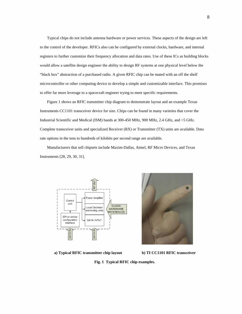
Figure 1 shows an RFIC transmitter chip diagram to demonstrate layout and an example Texas
Instruments CC1101 transceiver device for size. Chips can be found in many varieties that cover the
Industrial Scientific and Medical (ISM) bands at 300-450 MHz, 900 MHz, 2.4 GHz, and >5 GHz.
Complete transceiver units and specialized Receiver (RX) or Transmitter (TX) units are available. Data
rate options in the tens to hundreds of kilobits per second range are available.
Manufacturers that sell chipsets include Maxim-Dallas, Atmel, RF Micro Devices, and Texas
Instruments [28, 29, 30, 31].
a) Typical RFIC transmitter chip layout b) TI CC1101 RFIC transceiver
Fig. 1 Typical RFIC chip examples.

9
It is hoped that data rate performance for small spacecraft can be improved directly which will
increase utility and expand general capabilities. A system will be presented capable of rates in the 50,000
to 150,000 bps range. This system will be developed at the component level to maximize control over
requirements and performance, and engage the developer and users in radio frequency design at a deeper
level than can be achieved with a purchased “black box” solution. This system will be developed and
documented fully with the tools and capabilities at the university engineering level and captured by
configuration management practices to benefit future missions and programs.
Section II will review current alternatives to low performance radio systems and explore
developments in progress. Section III will define specific objectives and requirements for the RFIC
development. A system concept and associated trade studies will be developed in Section IV. Section V
details the preliminary design developed for the thesis. A verification plan and supporting analyses are
outlined in Sections VI and VII. Testing of the preliminary design is captured by Sections VIII and IX.
Proximity operations are discussed in Section X and modulation schemes are addressed in Section XI. A
conclusion featuring future work and lessons learned completes the thesis development in Section XII.

10
II. EXISTING SYSTEMS AND ALTERNATIVES
The RFIC project intends to increase downlink capability and robustness for small spacecraft
communications systems for microsatellites and nanosatellites. Sweeting defines the accepted
classification based on mass for satellites ranging from large satellites at over 1000 kg down to
microsatellites and nanosatellites at less than 100 kg and 10 kg respectively [1].
Kramer and Cracknell provide a comprehensive survey of small satellites from the beginning of the
space age to 2008 that includes all manner of spacecraft from both government agencies and universities
in the United States and abroad [32]. Swartwout provides an equally comprehensive survey that focuses on
“university class spacecraft,” defined as programs including training of university students as part of the
mission objectives [4]. Further spacecraft can be found in the Radio Amateur Satellite Corporation
(AMSAT) database [33]. Spacecraft listed by AMSAT are developed in support of, or are participating
secondarily in amateur radio activities. There is overlap between all three sources and a wide variety of
missions in the microsatellite and nanosatellite classes have been flown.
Generally speaking, the surveyed spacecraft can be split into two major categories that will be defined
here:
Government and Contractor Developed Missions: These missions are sponsored by governments and
militaries and built by the agencies themselves or by contractors of those agencies. These missions are
dominated by small spacecraft of all classifications that are delivered as either “one-off” products, or
as “turn-key” product lines of the same agencies and contractors. The full resources and well
developed capabilities of those entities are brought to bear to develop the spacecraft and associated
subsystems. Many of the United States missions of this type use the sophisticated NASA and Air
Force ground networks, and the NASA TDRSS relay network [18, 19, 20].
“University Class” and Research Organization Missions: These missions may be sponsored by
governments or militaries to meet specific mission goals, but are developed in house by individual

11
organizations regardless of the principal investigator or sponsor. These missions are dominated by
Swartwout’s “university class spacecraft,” and are characterized by the use of off the shelf and in-
house designs to accomplish mission goals. Many, but not all of these missions belong to the
“CubeSat” standard of spacecraft started by Cal Poly [6].
The second category is the target of the RFIC project. Organizations that do not have the resources of
a government or mature aerospace contractor require low-cost, novel, solutions to expand upon mission
capabilities.
Kramer and Cracknell’s history of spacecraft is dominated by mature spacecraft of the first category.
Communications systems in the space missions included in this history are continually moving towards the
use of increasing frequency bands from S through Ka band. [32]
With a few exceptions that will be covered shortly, the spacecraft with high speed data performance
feature systems designed and sold by the aerospace contractor community. Some of these are purchasable
outside of the context of “one off” missions such as those offered by SpaceQuest, AeroAstro, Surrey, or
other organizations [34, 25, 26]. These systems can provide over 1 Megabit/sec of downlink capability to a
spacecraft. Any program with sufficient resources can buy modules of this type that are space qualified
and add greatly to the capability of a given mission. For AggieSat Lab, purchase of this type of system is a
significant drain on program resources that could be spent solving the engineering problems associated
with mission objectives and research tasks.

12
Among the university class and research organization missions there are three more categories of
system types used as alternatives to the advanced systems. The most common category is amateur based
units that use off the shelf, low performance ham radio equipment that typically operate from 1,200 to
9,600 bps, with a few exceptions operating at higher rates. The second category features a fewer number
of custom systems that are developed in house by re-purposing miscellaneous hardware or designing radio
systems from scratch. The performance of some of these systems can compete with advanced contractor
developed units. In most of these cases the units eventually spin off as their own aerospace industry
products. These various exceptions will be examined later in this section.
Since 2005 a third category has been formed by organizations flying wireless modem modules
designed for ground based internet networks. They are intended to be a low cost solution that cannot
compete with advanced radio modules, but still improve upon the amateur category data rates by an order
of magnitude (>100,000 bps vs. 9,600 bps). The wireless modem solution was popularized by Santa Clara
University and the GeneSat-1 mission and promises data rates up to 172,000 bps [35].
The RFIC system is being developed as another alternative promising performance between 50,000 to
150,000 bps, and as will be explained later, seeks to improve upon drawbacks inherent to the wireless
modem solution.
Since cited histories end in 2008, recent flights that fit in with the stated definition for “University
Class” and Research Organization Missions that have occurred since then are featured in Table 1 for
context. All aforementioned categories of university class missions are represented.
13
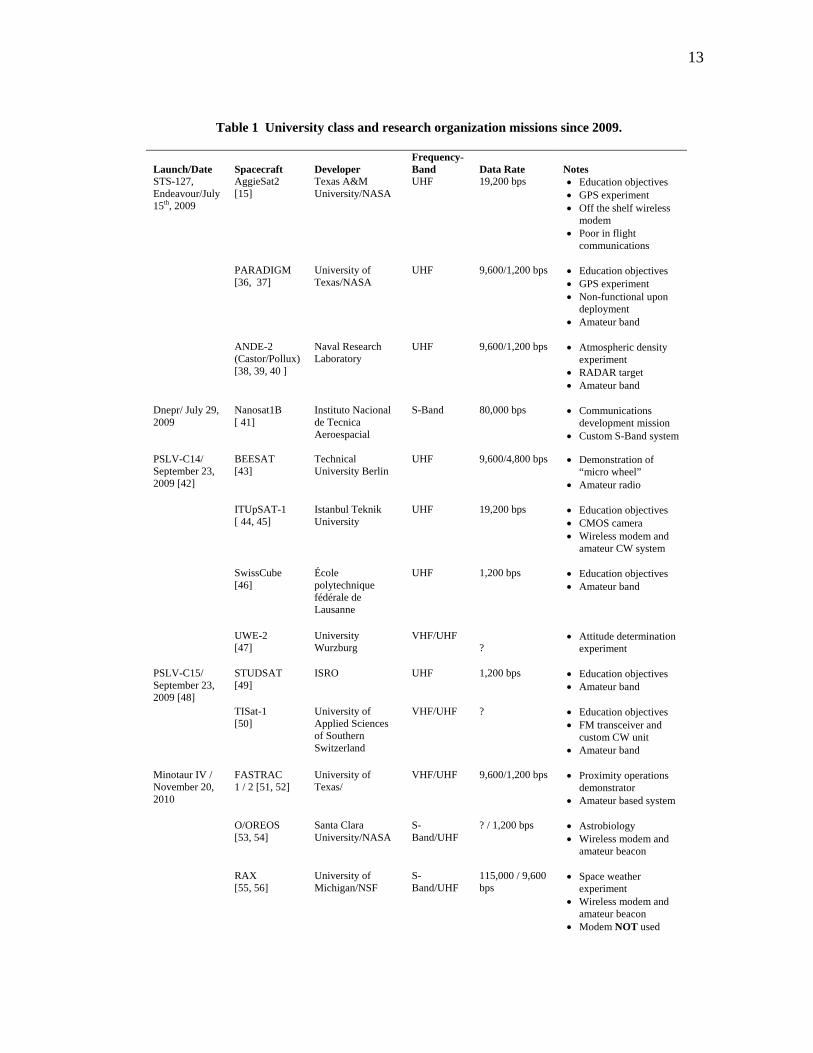
Table 1 University class and research organization missions since 2009.
Launch/Date
Spacecraft
Developer
Frequency- Band
Data Rate
Notes
STS-127, Endeavour/July 15th, 2009
AggieSat2 [15]
Texas A&M University/NASA
UHF 19,200 bps • Education objectives • GPS experiment • Off the shelf wireless
modem • Poor in flight
communications
PARADIGM [36, 37]
University of Texas/NASA
UHF 9,600/1,200 bps • Education objectives • GPS experiment • Non-functional upon
deployment • Amateur band
ANDE-2 (Castor/Pollux) [38, 39, 40 ]
Naval Research Laboratory
UHF 9,600/1,200 bps • Atmospheric density experiment
• RADAR target • Amateur band
Dnepr/ July 29, 2009
Nanosat1B [ 41]
Instituto Nacional de Tecnica Aeroespacial
S-Band 80,000 bps • Communications development mission
• Custom S-Band system
PSLV-C14/ September 23, 2009 [42]
BEESAT [43]
Technical University Berlin
UHF 9,600/4,800 bps • Demonstration of “micro wheel”
• Amateur radio
ITUpSAT-1 [ 44, 45]
Istanbul Teknik University
UHF 19,200 bps • Education objectives • CMOS camera • Wireless modem and
amateur CW system
SwissCube [46]
École polytechnique fédérale de Lausanne
UHF 1,200 bps • Education objectives • Amateur band
UWE-2 [47]
University Wurzburg
VHF/UHF ?
• Attitude determination experiment
PSLV-C15/ September 23, 2009 [48]
STUDSAT [49]
ISRO UHF 1,200 bps • Education objectives • Amateur band
TISat-1 [50]
University of Applied Sciences of Southern Switzerland
VHF/UHF ? • Education objectives • FM transceiver and
custom CW unit • Amateur band
Minotaur IV / November 20, 2010
FASTRAC 1 / 2 [51, 52]
University of Texas/
VHF/UHF 9,600/1,200 bps • Proximity operations demonstrator
• Amateur based system
O/OREOS [53, 54]
Santa Clara University/NASA
S-Band/UHF
? / 1,200 bps • Astrobiology • Wireless modem and
amateur beacon RAX [55, 56]
University of Michigan/NSF
S-Band/UHF
115,000 / 9,600 bps
• Space weather
experiment • Wireless modem and
amateur beacon • Modem NOT used

14
The majority of these flights feature amateur radio systems. Four of the thirteen missions are utilizing
off the shelf wireless radio modems, and only one is using a customized S-Band system.
A. Amateur Radio Systems
Amateur systems will be considered any satellite radio system configured by re-purposing voice and
data radio devices originally designed for operation in the licensed amateur radio service [57]. This type of
modem system is used for establishing packet networks that share data using amateur radios and Terminal
Node Controllers (TNC) [58]. TNC’s are modems with protocols specifically designed for licensed
amateur operation to convert digitized information into analog RF signals and back again. Most amateur
radio equipment is based on the AX.25 protocol.
The current standards for amateur packet radio originated in 1981 out of the Tucson Chapter of the
IEEE Computer Society and were established by the Tucson Amateur Packet Radio Corporation (TAPR)
[59]. The same performance, and in many cases the AX.25 protocol, is prevalent in the spacecraft listed in
Table 1 as well as in missions utilizing amateur radio listed by Kramer, Cracknell and Swartwout. The
majority of the data rates for these missions on into the 21st century have not exceeded 9,600 bps.
Amateur radio operator John Ackermann (N8UR, a former president of the Tucson Amateur Packet
Radio corporation from 2000-2005) suggests why 9,600 bps and higher rate systems have not matured in
amateur radio in his own essay [59]. He explains that 1,200 and 9,600 baud systems work well with
frequency modulated voice radios (which is what most store bought amateur radios are) and modification
is needed to increase speeds through this equipment. Modification and development from the amateur
radio community has not been forthcoming. Ackermann hints that this lack of development comes from
difficulty many amateurs have with this sort of modification and the fact that modern web based
communications and programs are competing with amateur radio and deflate efforts to improve the state
of the art (as Ackermann puts it “doesn’t provide the same experience that people have become
accustomed to with their Windows-based web browsers,”).
This is corroborated by Bedell who notes that the developments of TAPR are key achievements that
led to the development of other data protocols and the merging of wireless and data communications [58].
15
Indeed, the timeframe after the 1980’s is marked by a rapid growth in personal communications over
personal computers and mobile devices. The mobile devices that most are accustomed to are an entirely
different class of hardware apart from amateur radio equipment.
Even still, a few instances of 19,200, 38,400 and 56,000 bps equipment are mentioned by Ackermann
and can be found available from specialty companies [60, 61, 59]. Equivalent systems have not been
noticed among the university class and research organization spacecraft.
Even with a lack of development, amateur radio systems are well understood and established so the
prevalence among university and research organization missions is not surprising. Amateur radio
equipment is relatively inexpensive and accessible to hobbyists.
The history and legacy of amateur radio systems are also well established. The first non-government
satellites were the OSCAR spacecraft that served as beacons and repeaters for amateur radio
communications [62]. At 4.5 kg, OSCAR-1 was a nanosatellite in 1961 before Sweeting’s classifications
had been coined [32]. The amateur radio service has continued to design, integrate, and launch spacecraft
into the present day and has had decades to demonstrate flight results. The amateur community is large
and there are lots of resources available to assist hobbyists in participating in amateur satellite operations
[63, 64, 65]. AggieSat Lab’s own experience demonstrates that student engineers embrace this large
assemblage of collective information to grasp the basic problems of radio communication.
Amateur based systems have great flight heritage spanning many decades. Amateur radio systems can
be bought cheaply and there is an extensive support base and community to help with configuration of
these systems for flight. If a small satellite mission does not have great data download requirements then
these systems can be made to work well. Unfortunately there has been little or no progress in this area
since the 1980’s. This type of system does not facilitate improvements to small spacecraft capabilities.
B. Custom Systems
A custom system, built from scratch, is ideal for developing a specific tool to meet a set of
performance requirements. A small number of examples of custom development that are not part of an
effort by a major contractor or government agency have been attempted. Most of these efforts require a lot

16
of radio engineering expertise and end up spinning off into business units that join the aerospace
contractor community.
1. Systems Translated into Business Developments
The first efforts in this regard were attempted by the University of Surrey in England. The University
of Surrey has been experimenting with small spacecraft and focused on cost effective systems as far back
as 1979 with the UoSAT program [1].
UoSAT-1 through 5 were all amateur OSCAR spacecraft and featured 1,200 and 9,600 bps
communications [32]. This capability continued with spacecraft built in support of international
partnerships and technology transfer programs through 1992. From 1992-1998 Surrey was able to expand
this capability to 38,400 bps. A unique development was the UoSAT-12 spacecraft which featured the first
internet node in space using standardized internet protocols [66]. This system itself operated through an
existing 38,400 bps system onboard UoSAT-12 and replaced the AX.25 amateur system software
originally installed in the spacecraft. A spacecraft built by Surrey for the Chilean government flew with a
76,800 bps S-Band system in 1995 [32].
The S-Band unit was based upon a Field Programmable Gate Array (FPGA) processor and controller
area network interface with S-Band analog radio and amplifier components. Data rate is selectable as
38,400 or 76,800 bps [67].
Surrey itself has rolled these developments, along with others in many areas of spacecraft subsystem
design, into an aerospace company providing for small spacecraft specifically. Surrey formed the Surrey
Satellite Technology Ltd. Company to transfer developments to industry [1]. Surrey now offers turn key
satellite buses, payloads, and even S-Band, and X-Band transmitter systems that can provide data rates in
the hundreds of Megabits per second for missions that fit in our definition for government and contractor
developed missions [68].
Other organizations have followed a similar path to Surrey. The Technical University (TU) of Berlin
developed a 125,000 bps S-Band system for the transmission of analog and digital earth resources
television frames that flew on their DLR-TUBSAT and LAPAN-TUBSAT missions [69, 70, 32]. The
17
Korea Advanced Institute of Science and Technology flew a 38,400 bps S-Band system on KITSAT-3 in
1999 [71]. Since these efforts, both TU Berlin and Korea Advanced Institute of Science and Technology
have rolled developments into business units that offer products similar to Surrey’s [72, 73].
The Nanosat1B mission in Table 1 was developed by the Instituto Nacional de Tecnica Aeroespacial
of Spain and flew with an 80,000 bps system [41]. The institute developed this system with a company
called AD Telecom and they are currently working on a 2 Mbps system.
Unfortunately, all of these efforts have led to, or been closely tied to the development of business
units to market the radio systems. While these have been very good research and development efforts, the
end product has diverged into the realm of government and contractor developed missions.
2. The Kansas State University RFIC Effort
An RFIC effort for Mars mission applications has been developed by William Kuhn at Kansas State
University (KSU) [74, 75]. Kuhn’s team has been working with NASA Jet Propulsion Laboratory (JPL) to
implement a low power, volume and mass UHF radio for planetary exploration. This development takes
place at the Integrated Circuit design and fabrication level, which is an entire level of complexity above
that planned for the RFIC project.
This design is intended for deep space operations. It can tolerate temperatures up to minus 100
degrees C and uses a special process developed by a company called Peregrine Semiconductor for
radiation hardness [74].
While this radio unit is quite advanced by nature of precautions taken for environmental factors, it
only transmits at 8,000 bps [74]. The design tradeoffs favor deep space operations and do not suit small
spacecraft for Low Earth Orbit (LEO) that require high data rate capability. Since the RFIC chip is
designed and fabricated from scratch, it requires sophisticated radio design capabilities. The development
has been shared between KSU and JPL and oversight has been given by Peregrine Semiconductor
Corporation [76].
The RFIC project proposed for this thesis utilizes higher speed, off the shelf RFIC’s rather than
undertaking a chip level design effort. The commercial chips are to be low cost and re-purposed from
18
ground based applications and do not feature advanced processes for radiation hardness and other deep
space environmental requirements.
3.CANX-2
The University of Toronto Institute for Aerospace Studies Space Flight Laboratory (UTIAS/SFL)
flew a spacecraft named CANX-2 in 2008 based on the 3U variant of the CubeSat standard [77].
The spacecraft included a custom experimental S-Band communications system capable of rates
between 8,000 bps and 1 Mbps. This system was tested in flight at rates between 32,000 and 256,000 bps
[78]. The custom radio interfaces with a ground station utilizing a controller on a single board computer
with custom software, and a commercially available S-Band modem unit [79].
This system works at the target data rates of the RFIC project and appears to be based largely on in
house programming and hardware work. With continued success it can be a useful addition to the field of
available radio systems. The unit was flown again at rates between 32,000 and 256,000 bps as part of the
AISSat-1 maritime surveillance spacecraft built by UTIAS/SFL on behalf of the Norwegian government
[80].
4. ISIS S-Band System
The AggieSat4 team at Texas A&M has specified a S-Band radio unit developed by the Innovative
Solutions In Space (ISIS) company, operating at 38,400 bps for “high speed” downlink [81]. ISIS was
formed in 2006 by team members from the Delfi-C3 nanosatellite project by the Delft University of
Technology (TU Delft) and offers nanosatellite subsystems for sale [82].
Delfi-C3 was launched in 2008 to test a new type of thin film solar cells and sun sensors. Delfi-C3
used 1,200 bps, AX.25, amateur radio equipment [83].
No flight history has been found for the new S-Band radio developed by the TU Delft/ISIS team. The
radio is priced at approximately U.S. $12,300 [81]. It is expected the proposed RFIC solution can
outperform 38,400 bps data rates, while maintaining development control and understanding of design at
the organization’s own level.

19
5. SwRI Reconfigurable S-Band Software Defined Radio for Small Satellite Applications
A very promising alternative is offered by the Southwest Research Institute (SwRI) of San Antonio,
Texas. SwRI has worked for years developing spacecraft and instruments for NASA, the military, and the
European Space Agency [84]. They are unique in that as of 2011 they are beginning to publicize a new S-
Band system that is being developed from the beginning with the small satellite market, in particular the
CubeSat market, in mind.
In this rare instance a larger player in the aerospace field is bringing to bear the resources of a mature
organization accustomed delivering for government contracts upon a problem for smaller space vehicles.
Objectives for this project are to deliver a reconfigurable RF system that can support multiple
frequency bands, to implement a system using the PC/104 computer standard form factor to make it
compatible with CubeSats, and to build a system that is radiation tolerant to expand operational altitude
ranges out into Medium Earth Orbit (MEO) [84]. The reported data rates for the transceiver are 2 kbps and
3 Mbps between two separate radio service blocks. Both services are controlled through a Software
Defined Radio (SDR) operated on a Field Programmable Gate Array (FPGA) system.
In many ways this radio could offer the ideal solution to what many in the small satellite community
have been looking for. The objectives for the radio are very similar to those offered here for the RFIC
thesis project. SwRI’s focus on this sector of the market itself is noble. If this unit is successfully
completed, marketed, and flown it will surpass the capabilities of the RFIC solution proposed here.
The S-Band system by SwRI was presented in August of 2011 at the 25th AIAA/USU Conference on
Small Satellites and has yet to be flight tested and marketed. Time will allow functionality to be tested, the
product to be developed, and for the community to see what cost this capability can be made available for.
20
C. Commercial Wireless Modem Systems
General wireless, WLAN and “radio” modems shall be considered any commercially available data
modems that are intended for establishing licensed or unlicensed private radio networks that aren’t
specifically intended for the amateur radio service. In general, these modems operate in specific frequency
allocations (such as the ISM bands) that do no require stringent licensing. Four of the missions in Table 1
utilized these modems. [85]
Despite recent popularity, these modems present challenges to space operations. They are designed
for use with ground networks and use spread spectrum methods to maximize the allowable number of
users on a given band [85]. This requires a radio to either spread signal energy over the band or requires
the radio to change frequency rapidly according to proprietary handshaking and logic. Spread energy
systems have lower output power relative to noise bandwidth and frequency hopping systems require
synchronization and coding to understand the “hops” making frequency control in the face of
environmental factors a challenge [86]. The manufacturer for AggieSat2’s radio controlled the sequence
making it impossible for AggieSat2 to control the pattern or compensate. A spread energy scheme would
undoubtedly have problems with range due to noise.
The MEPSI spacecraft series, built by the Aerospace Corporation, is the earliest instance found of
commercial wireless modems in spaceflight. The MEPSI spacecraft are designed as demonstrators for
small satellite based inspector spacecraft [87]. Two pairs of MEPSI spacecraft flew each in 2002 and 2006
on STS-113 and STS-116 respectively. Both sets of spacecraft utilized a modified version of the Freewave
FGRM 915 MHz wireless modem and large 60 foot antenna site provided by SRI International at Menlo
Park, California [88, 89]. The first pair, deployed from Space Shuttle Endeavour, successfully beaconed,
but did not operate successfully due to an untested gain issue with the radios.
The second set deployed from Space Shuttle Discovery in 2006. Proper radio attenuation testing was
performed and the pair successfully returned photographs of the Shuttle Orbiter to the ground. [87]
In 2006 Santa Clara University flew the GeneSat-1 spacecraft to demonstrate in-situ biological
research and processing on a small spacecraft [90]. Santa Clara was the first university class mission to
attempt this method. The spacecraft used a radio system based upon the Microhard MHX2400 wireless
21
modem to investigate use of these types of modems to improve small spacecraft capabilities. The
MHX2400 operates on the 2.4 GHz ISM band [91]. The Microhard radios offer high output power (1
Watt) but are frequency hopping.
In preparation for flight, the GeneSat-1 team performed qualification tests to demonstrate resilience to
expected Doppler shift, delays induced by range that could interfere with synchronization and spread
spectrum logic, and environmental stresses. The team also utilized the large 60 foot parabolic ground site
antenna provided by SRI International adding approximately 40-50 dB gain to their link budget. The
GeneSat-1 team was able to successfully use approximately 80% of their predicted satellite access time
during operations with a useable 83,000 bps of data rate [35].
Based upon this success, the AggieSat2 team at Texas A&M University selected the MHX425 modem
for use on the AggieSat2 spacecraft in 2009. AggieSat2 was a 5” cubic satellite designed and built in
house at Texas A&M to carry a GPS receiver built by NASA JSC for use in space navigation. This
objective is part of the multi-mission campaign now underway by NASA JSC, AggieSat Lab, and the
University of Texas to advance ARD technologies. The AggieSat team intended to use the MHX425 radio
at a data rate of 19,200 bps and rely on its compact size (~ 3.5” x 2”) to fit within the extreme constraints
of the 5” satellite bus.
AggieSat team members had similar concerns about Doppler shift and timing as the GeneSat team,
but far less experience. Attempts were made at first to work with Microhard Corporation to modify the
unit’s software to offer tuning control, but these were unsuccessful. The company was unable to spare the
resources for the software changes for such a low volume project. As a stopgap measure, a feature was
incorporated into the ground station software to allow a user defined table to be changed quickly on the
ground station MHX unit. This table specified the hopping sequence of the MHX425. The idea was to re-
write the table to feature a common frequency throughout so the radio would continually hop to one
channel. If a tuning adjustment was needed, the command could be sent and the table rapidly re-written.
In practice the table feature was successful in fixing the receive frequency, but operators did not have
enough feedback on the spacecraft signal to tune successfully. Early on the AggieSat team could receive
spacecraft beacons, but not affect commands. Eventually, the AggieSat team was able to add amplifiers

22
and perform modifications on the ground segment which allowed AggieSat2 to be contacted routinely, but
only for about a quarter of expected pass durations. All operations continued to take place on a fixed
frequency without tuning control. AggieSat also could not leverage other amateur operators to assist
because they did not have MHX425 units that could interface with the proprietary handshaking protocols.
It is thought that the inability to tune contributed greatly to the inconsistent communications, but the
extent at which this contributed is unknown. AggieSat2 had also suffered a separation failure from its
counterpart satellite, Bevo-1, upon separation from Space Shuttle Endeavour. While the spacecraft was
able to function, the failure placed the MHX425’s antenna in an unknown state [13].
The separation failure adds another variable to the situation, but Doppler shift problems cannot be
completely ruled out. At GeneSat-1’s operational orbit and data rate the expected Doppler shift is reported
as ~55 kHz, while the channel bandwidth of the radio system is ~400 kHz [35]. This means that the
Doppler shift on GeneSat-1 can cause the signal energy to shift out of band by as much as 14% of the
channel width. For AggieSat2, the approximate Doppler shift can be a maximum of ~10 kHz and the
channel width was ~38 kHz. AggieSat2 could potentially suffer from shifting the signal energy by as much
as 26% of the channel width. GeneSat-1 also featured a large ground segment with a ~40 dB, 60 foot
antenna to offset signal loss, while AggieSat2 only featured a ~18 dB ground antenna. In both cases, signal
energy is shifting out of band partially due to Doppler shift. This shift occurs on a higher percentage of
channel bandwidth on AggieSat2, while gain margins are much lower due to a smaller ground segment,
resulting in a fear that Doppler effects on received carrier power could been significant.
This initial flight history demonstrates the complex nature of adopting these systems for spaceflight.
Users must accept these radios as built from manufacturers and work around the limited interfaces and
controls. GeneSat-1’s success can be attributed to the diligent testing and development they were able to
complete in addition to large margins built into the system. MEPSI utilized the same SRI ground segment
and also included large margins in the downlink system. AggieSat Lab struggled through the entire
process independently and had very poor flight results.
Since MEPSI, GeneSat-1, and AggieSat2 more missions have used these modem types for
spaceflight. In September of 2009 the Istanbul Technical University’s (ITU) Space Systems Design and
23
Test Laboratory flew a CubeSat called ITUpSAT 1 featuring an MHX425 modem like AggieSat2’s. The
spacecraft was designed to provide satellite construction experience to the students and faculty at ITU and
feature a low resolution camera. [44]
Very little information on ITUpSAT 1’s performance is available. Amateur radio operator Wouter
Weggelaar, PA3WEG (amateur radio operator, RF engineer, and contributor to the Delfi-C3 spacecraft
effort at the Delft University of Technology in the Netherlands) was among the operators who attempted
to assist ITU in operations soon after launch [92, 93]. He posted information to his own satellite blog in
November of 2009 about this effort. This post asserts that ITU itself was unable to connect to the
spacecraft. PA3WEG mentions that ITU was attempting to add amplification to the ground system to
overcome this and that PA3WEG was working with a member of the ITU team and a second Microhard
radio to attempt communications of their own [94]. No further updates on this effort were found.
PA3WEG’s short summary sounds similar to the experience with AggieSat2 and since that time, no
evidence of mission data or imagery has been found posted or in literature. As of September of 2010, ITU
was celebrating the first year anniversary of ITUpSAT 1’s launch and called for radio amateurs to
continue to report beacons [95]. This indicated general aliveness of ITUpSAT 1, but does not show
evidence of other mission data results.
Since GeneSat-1, the Santa Clara team has continued to refine their success with the MHX2400
modems. For future missions the Santa Clara team developed smaller, 3 meter dish antenna ground
systems to see if the MHX2400 based satellite radio could be used by smaller ground segments. They
tested this new ground segment and the latest generation of MHX 2.4 GHz modems, the MHX2420, with
GeneSat-1. It is not reported how much data or access time has been achieved, but it is reported that link
margins between 0 and 19 dB over antenna elevations from 10 to 78 degrees have been obtained [96]. This
suggests communications could be maintained with the smaller systems.
In November of 2010 the Santa Clara team launched the O/OREOS spacecraft as the first mission of
the NASA Astrobiology Small-Payloads Program. This mission is a technology demonstrator and is
carrying a MHX2420 radio unit and utilizing the smaller ground station setup in addition to a UHF/VHF
beacon system [53, 54].
24
As of June of 2011, the O/OREOS operations page lists the S-Band system as “operational”, but it is
unknown how much data is being successfully processed by this system [97]. O/OREOS also features an
“operational” UHF beacon that may or may not be part of general data operations for the spacecraft.
Finally, the University of Michigan is currently flying an MHX2400 unit at 115,000 bps along with a
UHF transceiver onboard the RAX spacecraft. RAX is designed to study plasma in the ionosphere by
measuring ground based RADAR scatter. RAX is being supported by SRI international which partnered
with Santa Clara and lent the large ground station for use with the original MHX2400 system onboard
GeneSat-1 [55, 56].
Dr. Cutler at the University of Michigan confirmed* that the MHX2400 system has not been used on
RAX. This was on the basis that the UHF system consumes less power (there had been a solar panel
problem in flight), and that it is easier to coordinate with ground stations using the UHF system [98].
The stated flight history and success with MHX type modems is mixed. Santa Clara’s results with the
MHX2400 and 2420 units show promise and suggests off the shelf modems are a worthwhile path of
development.
Alternatively, AggieSat Lab and ITU encountered difficulty in making contacts and the proprietary
protocols used on the radios prevented widespread help from the amateur radio community. The RAX
team, in part, opted not to use their system to make ground station coordination easier. In all cases the
radio modems have been used without modification and the default interfaces have contributed to
difficulties in implementation.
Santa Clara has been making efforts to ultimately prove whether or not large ground segments and the
added link margin are required to make these links effective. A smaller ground segment could be
implemented by a wider range of organizations for mission operations to increase the effective time
available to download data. Since that effort has started, the O/OREOS spacecraft has been operated by
Santa Clara with a smaller scale ground segment, but more information is needed to see if this has been
successful.
____________ *Private correspondence with Dr. James Cutler of the University of Michigan from Jan 25th-June 15th 2011.
25
Further flight demonstrations of other devices in this class would also add value to efforts to expand
the downlink capabilities of small spacecraft. However, since all commercial radio modems are designed
to operate in ground networks as per the stated definitions, there is a distinct possibility that other modem
systems will feature similar challenges to the MHX series.
The RFIC based system is offered as a “third way” among continued development of the MHX2400
path which has enjoyed repeated flight history, and alternative wireless radio modems which to date
remain unexplored outside of Aerospace Corporation’s experience with MEPSI. Radio modems that meet
the referenced definitions will continue to feature sub-optimal interfaces and protocols relative to small
spacecraft mission requirements.
D. The RFIC Thesis Project
A preferable communications system would offer similar performance to wireless modems but feature
an interface and controls tailored to the needs of spaceflight operations. Ideally such a system would be
low cost, and allow the user responsibility in construction and configuration of the device to maximize
understanding of operation and performance.
The RFIC based system proposed in this thesis seeks to do this by starting development at the
component level, rather than starting with a “black box” featuring fixed interfaces designed for unrelated
ground networks.

26
III. SYSTEM OBJECTIVES AND REQUIREMENTS DEFINITION
The RFIC based radio solution shall be developed through a top down systems engineering approach.
The RFIC system will be defined by specific performance and documentation requirements. The thesis
will encompass conceptualization, design, proof of concept prototype development, and the beginning of
the verification process.
A. System Objectives
From Section I our problem statement is as follows:
Can a useful spacecraft communications building block be built from commercially available Radio
Frequency Integrated Circuits and improve upon overall data rate performance, control, and robustness
for downlink and proximity operations applications?
Can this system be designed, built and captured using and improving upon student satellite design and
engineering capabilities?
Our design focus is directed towards improving data rate performance, control, and robustness of
small satellite communications systems. To address data rate performance we wish to improve upon
current lab capabilities without involving expensive government and contractor based solutions. The
history of contemporary systems demonstrates that a significant number of systems operate at or below
9,600 bps. We wish to exceed this performance to compete with many of the custom or modem based
systems described in Section II.
Furthermore, AggieSat4 has specified a commercial S-Band system developed by the Innovative
Solutions In Space (ISIS) CubeSat components vendor. This unit does not have a flight history, but is
quoted at typical data rates of 38,400 bps [81]. Our improved system should at least exceed this

27
performance to affect near term developments at AggieSat Lab. The proposed system detailed later is
expected to be able to achieve rates between 50,000 and 150,000 bps which will compete with alternatives
listed in Section II. We can use the lower bound of 38,400 to establish a minimum data rate performance
target.
The link for the proposed system should also close with signal power margin in a typical Low Earth
Orbit (LEO) for small spacecraft. AggieSat Lab spacecraft have been limited to orbits similar to the
International Space Station near 300 km surface altitude. A 350 km orbit, or lower, will meet the current
range of planned missions at AggieSat. This link should be closed between 10 degrees above the horizon
and zenith to provide good ground station coverage to ensure usable downlink.
It is also important to include frequency agility as a goal for the design. Frequency agility is defined
here as the capability to tune and have knowledge of the radio’s main carrier frequency(ies) operationally
without severely impacting time spent communicating data payload. This is to avoid problems inherent in
with Doppler shift and Frequency Hopping Spread Spectrum (FHSS) designs as mentioned in Section II.
Finally, it is important for the system design to be captured and reported to improve small spacecraft
design capabilities for the future. This thesis, associated design documentation and test results will satisfy
this need.
28
Upon this overall premise we define the following objectives:
1. Develop a university class radio system building block using RFICs and evaluate performance for
small spacecraft applications.
• Characterize usefulness in a downlink application with the intent on overcoming existing
solution problems. e.g. frequency agility and error tolerance to counteract Doppler shift and
other center frequency errors, a data rate >38,400 bps, and signal performance to allow
downlink segments to close link at 10 degree elevation for a 350 km orbit.
• Characterize usefulness in a proximity operations application. e.g. range performance and
two way, half duplex, data transfer capability.
• Characterize the building block in relation to small satellite specific issues including, but not
limited to, mass, power, volume, and if possible thermal and radiation performance.
2. Capture the requirements, design, results, and lessons learned for further RF component
development to improve satellite design capabilities.
Objective 1 includes characterization of the system in relation to proximity operations (close range
communications for tandem spacecraft operations), and for space environment concerns. Proximity
operations performance will be briefly examined later. The proposed RFIC system has advantages in size
and power which could make it useful for such operations. This is useful to near term AggieSat Lab goals.
Space environment concerns will largely be addressed by using standard practices for the construction of
space electronics. The thesis is focused on establishing a proof of concept design.
B. System Requirements
Table 2 lists the system level requirements based upon the objectives for this development.

29
Table 2 RFIC project system requirements.
Requirement Description Source RF-1 Develop a university class radio system building block
using RFICs. Objective 1
RF-2 The radio system must utilize bands that are legally available to AggieSat Lab or can be licensed for use and comply with regulations pertaining to those bands.
AggieSat Lab
RF-3 Characterize the building block in relation to mass, power, volume, and, if possible, thermal vacuum, and radiation performance.
Objective 1
RF-4 Capture the requirements, design, results, and lessons learned for further RF component development to improve lab satellite design capabilities.
Objective 2
RF-5 The developed system must be designed to operate in a low earth orbit (LEO) environment for at least 6 months (thermal, vacuum, radiation).
AggieSat Lab
RF-6 The developed radio system must be capable of being frequency agile as defined by objective 1 as to address problems related to space operations.
Objective 1
RF-7 The developed radio system must have an average throughput of 38,400 bps or better.
Objective 1
RF-8 The developed radio system must have a broadcast power to allow downlink segments to close link at 10 degree elevation for a 350 km orbit.
Objective 1
RF-9 The developed radio system must be capable of communicating to a minimum range of 0 to 1 km.
Objective 1, AggieSat Lab
RF-10 The developed radio system must be capable of two way, half duplex, data operations in proximity operations applications.
Objective 1
All requirements directly apply to objectives 1 and 2 with the exception of RF-2, 5, and 9. RF-2 is
was added to enforce compatibility of the designed system with communication laws levied by the Federal
Communications Commission and international regulatory bodies while RF-5 and 9 are present to fit in
with AggieSat Lab development efforts for AggieSat4.
30
IV. SYSTEM CONCEPT DEFINITION
The selected system concept is based on a commercially available RFIC chip and microcontroller
pairing. An array of commercial RFIC chips must be traded against the requirements stated in Section III.
A shorter trade study of available microcontrollers must also be conducted and focused on finding an
acceptable microcontroller unit that is easy to develop, has likelihood of surviving the space environment,
and can allow a user to develop a proper interface.
A. RFIC Device Trade Space and Selection
The following criteria, based upon the mission requirements, are used to narrow chip selection in the
order of importance:
• Licensing – The considered chipsets must be capable of broadcasting in either unlicensed bands or
bands that have licensing that can be obtained by AggieSat Lab to satisfy RF-2. AggieSat Lab has
experience with amateur and ISM licensing in particular. This is set as the first criteria as there is no
point in using equipment that AggieSat Lab cannot implement legally.
• Frequency Agility/Tuning – The selected chipset must be able to be tuned operationally to combat
Doppler shift and make the carrier signal frequency predictable to satisfy RF-6. While both
downlink and proximity applications are being considered in this project, the downlink
requirements drive the overall design as the fundamental problems in small satellite
communications are space to ground link issues.
• Downlink Performance – The selected chipset must be shown to have a high likelihood of meeting
downlink power and data rate requirements to close the link for LEO operations and satisfy RF-7
and 8. The link performance will be analytically estimated by considering power output,
modulation, data rate and bandwidth, and sensitivity.
• Proximity Link Performance – The selected chipset must be shown to have good performance,
primarily in range, for proximity link applications as per RF-9 and 10. This is considered to be the
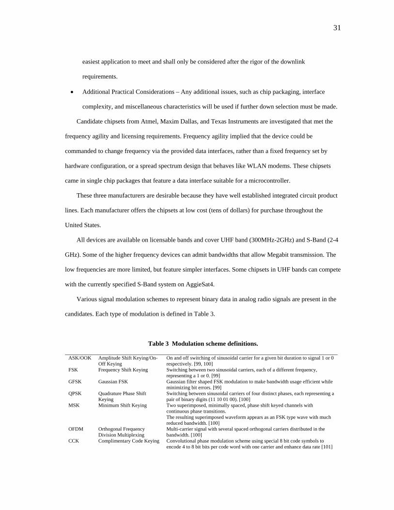
31
easiest application to meet and shall only be considered after the rigor of the downlink
requirements.
• Additional Practical Considerations – Any additional issues, such as chip packaging, interface
complexity, and miscellaneous characteristics will be used if further down selection must be made.
Candidate chipsets from Atmel, Maxim Dallas, and Texas Instruments are investigated that met the
frequency agility and licensing requirements. Frequency agility implied that the device could be
commanded to change frequency via the provided data interfaces, rather than a fixed frequency set by
hardware configuration, or a spread spectrum design that behaves like WLAN modems. These chipsets
came in single chip packages that feature a data interface suitable for a microcontroller.
These three manufacturers are desirable because they have well established integrated circuit product
lines. Each manufacturer offers the chipsets at low cost (tens of dollars) for purchase throughout the
United States.
All devices are available on licensable bands and cover UHF band (300MHz-2GHz) and S-Band (2-4
GHz). Some of the higher frequency devices can admit bandwidths that allow Megabit transmission. The
low frequencies are more limited, but feature simpler interfaces. Some chipsets in UHF bands can compete
with the currently specified S-Band system on AggieSat4.
Various signal modulation schemes to represent binary data in analog radio signals are present in the
candidates. Each type of modulation is defined in Table 3.
Table 3 Modulation scheme definitions.
ASK/OOK Amplitude Shift Keying/On-Off Keying
On and off switching of sinusoidal carrier for a given bit duration to signal 1 or 0 respectively. [99, 100]
FSK Frequency Shift Keying Switching between two sinusoidal carriers, each of a different frequency, representing a 1 or 0. [99]
GFSK Gaussian FSK Gaussian filter shaped FSK modulation to make bandwidth usage efficient while minimizing bit errors. [99]
QPSK Quadrature Phase Shift Keying
Switching between sinusoidal carriers of four distinct phases, each representing a pair of binary digits (11 10 01 00). [100]
MSK Minimum Shift Keying Two superimposed, minimally spaced, phase shift keyed channels with continuous phase transitions. The resulting superimposed waveform appears as an FSK type wave with much reduced bandwidth. [100]
OFDM Orthogonal Frequency Division Multiplexing
Multi-carrier signal with several spaced orthogonal carriers distributed in the bandwidth. [100]
CCK Complimentary Code Keying Convolutional phase modulation scheme using special 8 bit code symbols to encode 4 to 8 bit bits per code word with one carrier and enhance data rate [101]
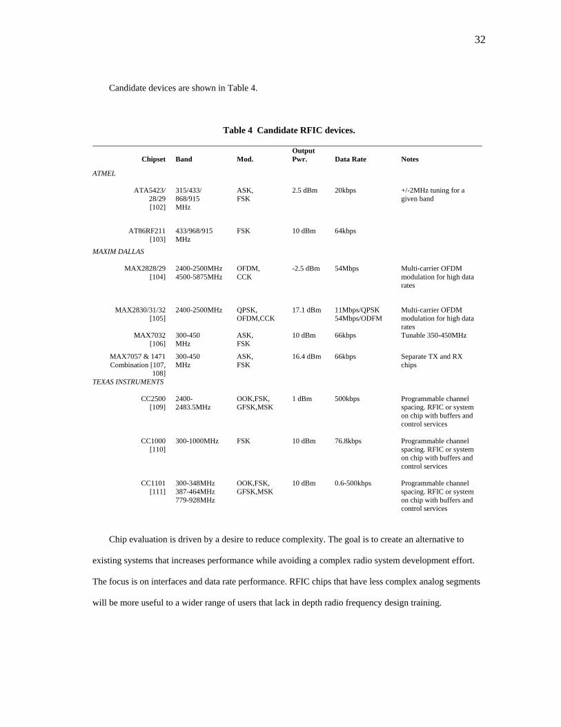
32
Candidate devices are shown in Table 4.
Table 4 Candidate RFIC devices.
Chipset
Band
Mod.
Output Pwr.
Data Rate
Notes
ATMEL
ATA5423/ 28/29 [102]
315/433/ 868/915 MHz
ASK, FSK
2.5 dBm 20kbps +/-2MHz tuning for a given band
AT86RF211 [103]
433/968/915 MHz
FSK 10 dBm 64kbps
MAXIM DALLAS
MAX2828/29 [104]
2400-2500MHz 4500-5875MHz
OFDM, CCK
-2.5 dBm 54Mbps Multi-carrier OFDM modulation for high data rates
MAX2830/31/32 [105]
2400-2500MHz QPSK, OFDM,CCK
17.1 dBm 11Mbps/QPSK 54Mbps/ODFM
Multi-carrier OFDM modulation for high data rates
MAX7032 [106]
300-450 MHz
ASK, FSK
10 dBm 66kbps Tunable 350-450MHz
MAX7057 & 1471 Combination [107,
108]
300-450 MHz
ASK, FSK
16.4 dBm 66kbps Separate TX and RX chips
TEXAS INSTRUMENTS
CC2500 [109]
2400-2483.5MHz
OOK,FSK, GFSK,MSK
1 dBm 500kbps Programmable channel spacing. RFIC or system on chip with buffers and control services
CC1000 [110]
300-1000MHz FSK 10 dBm 76.8kbps Programmable channel spacing. RFIC or system on chip with buffers and control services
CC1101 [111]
300-348MHz 387-464MHz 779-928MHz
OOK,FSK, GFSK,MSK
10 dBm 0.6-500kbps Programmable channel spacing. RFIC or system on chip with buffers and control services
Chip evaluation is driven by a desire to reduce complexity. The goal is to create an alternative to
existing systems that increases performance while avoiding a complex radio system development effort.
The focus is on interfaces and data rate performance. RFIC chips that have less complex analog segments
will be more useful to a wider range of users that lack in depth radio frequency design training.

33
The Maxim Dallas MAX 2828, 29, 30, 31, and 32 offer excellent data rates in the tens of Mbps range.
This is achieved by utilizing OFDM carriers that feature multiple signals spread in the bandwidth. Each of
the carriers can transmit a separate portion of the data in parallel. These Maxim chips are also optimized
for 802.1 Wireless LAN Applications. [104, 105]
The Maxim 28XX series chipsets were rejected on the basis of complexity. The eventual evolution of
the RFIC system should feature custom matching networks built from capacitors and inductors to optimize
output for antenna systems. These matching networks adjust the “electrical length” of signals to minimize
voltage reflections. The multiple inputs and outputs on the analog side of the circuit could potentially
complicate matching work for users that do not have extensive RF experience. While not selected for this
development effort, these chips may be useful devices for future iterations of the overall concept to push
performance beyond that achieved here.
Introductory text on OFDM signals also indicates that OFDM signals are particularly susceptible to
frequency shifts and phase noise over single carrier methods [100]. Tuning and Doppler shift
compensation are key parts of this design development and the possibility of complications with frequency
shifting is undesirable for proof of concept development.
Remaining chips include the Atmel 5423 family, Atmel AT86RF211, Maxim Dallas 7032, Maxim
7057 and 1471 combination, and Texas Instruments CC1000, 1101, and 2500 series of chips.
Among these, the Atmel 5423 family performed at 20,000 bps data rate. It was rejected outright based
on requirement RF-7 to be greater than 38,400 bps.
The Maxim Dallas 7057 and 1471 combination was rejected due to complexity and performance. This
system needs individual chips for TX and RX which requires separate interface work. It also means that
individual pairs of chips are incapable of two way communications for proximity operations. The
combination is also limited by the 66,000 bps data rate of the 1471 receiver. Other transceiver chips in the
trade space feature higher raw data rates and two way capability on one chip.
The AT86RF211, MAX7032, and Texas Instruments chips all featured similar interfaces suited to
quick development with a microcontroller. All feature a synchronous Serial Peripheral Interface (SPI) that
features a coordinating clock signal and separate transmit and receive lines for full duplex controller to
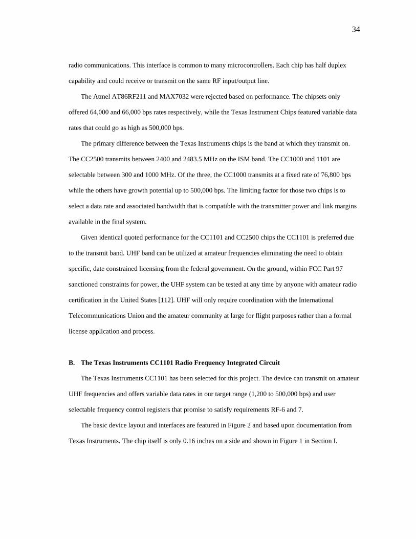
34
radio communications. This interface is common to many microcontrollers. Each chip has half duplex
capability and could receive or transmit on the same RF input/output line.
The Atmel AT86RF211 and MAX7032 were rejected based on performance. The chipsets only
offered 64,000 and 66,000 bps rates respectively, while the Texas Instrument Chips featured variable data
rates that could go as high as 500,000 bps.
The primary difference between the Texas Instruments chips is the band at which they transmit on.
The CC2500 transmits between 2400 and 2483.5 MHz on the ISM band. The CC1000 and 1101 are
selectable between 300 and 1000 MHz. Of the three, the CC1000 transmits at a fixed rate of 76,800 bps
while the others have growth potential up to 500,000 bps. The limiting factor for those two chips is to
select a data rate and associated bandwidth that is compatible with the transmitter power and link margins
available in the final system.
Given identical quoted performance for the CC1101 and CC2500 chips the CC1101 is preferred due
to the transmit band. UHF band can be utilized at amateur frequencies eliminating the need to obtain
specific, date constrained licensing from the federal government. On the ground, within FCC Part 97
sanctioned constraints for power, the UHF system can be tested at any time by anyone with amateur radio
certification in the United States [112]. UHF will only require coordination with the International
Telecommunications Union and the amateur community at large for flight purposes rather than a formal
license application and process.
B. The Texas Instruments CC1101 Radio Frequency Integrated Circuit
The Texas Instruments CC1101 has been selected for this project. The device can transmit on amateur
UHF frequencies and offers variable data rates in our target range (1,200 to 500,000 bps) and user
selectable frequency control registers that promise to satisfy requirements RF-6 and 7.
The basic device layout and interfaces are featured in Figure 2 and based upon documentation from
Texas Instruments. The chip itself is only 0.16 inches on a side and shown in Figure 1 in Section I.
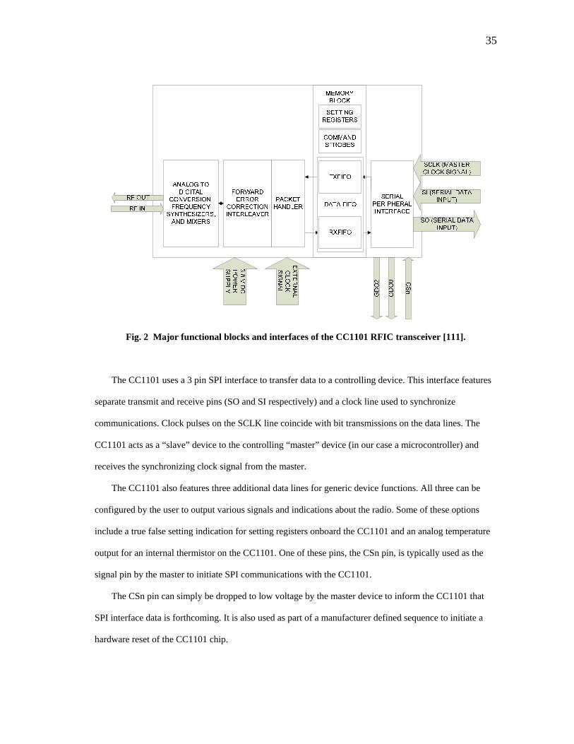
35
Fig. 2 Major functional blocks and interfaces of the CC1101 RFIC transceiver [111].
The CC1101 uses a 3 pin SPI interface to transfer data to a controlling device. This interface features
separate transmit and receive pins (SO and SI respectively) and a clock line used to synchronize
communications. Clock pulses on the SCLK line coincide with bit transmissions on the data lines. The
CC1101 acts as a “slave” device to the controlling “master” device (in our case a microcontroller) and
receives the synchronizing clock signal from the master.
The CC1101 also features three additional data lines for generic device functions. All three can be
configured by the user to output various signals and indications about the radio. Some of these options
include a true false setting indication for setting registers onboard the CC1101 and an analog temperature
output for an internal thermistor on the CC1101. One of these pins, the CSn pin, is typically used as the
signal pin by the master to initiate SPI communications with the CC1101.
The CSn pin can simply be dropped to low voltage by the master device to inform the CC1101 that
SPI interface data is forthcoming. It is also used as part of a manufacturer defined sequence to initiate a
hardware reset of the CC1101 chip.
36
Data going to and from the CC1101 is processed and distributed through the onboard memory
featured in the CC1101. The memory is subdivided into addresses for settings, command strobes, and the
data First In First Out (FIFO) buffer.
Device control memory is divided into settings and command strobes. The setting registers each hold
a byte value representing a particular setting for the chip’s operation. The command strobes are stored byte
blocks that can be quickly sent by the master device to the CC1101 and instantly recognized to cause
major mode events. These major events include reset and calibration actions and activation of transmit and
receive operations when desired.
The data FIFO acts as a buffer for all incoming and outgoing radio payload data. The FIFO itself is 64
bytes long. The 64 bytes can be allocated in increments of 4 bytes for transmit and receive buffer space.
For a downlink application the transmit unit can be configured to provide all 64 bytes to the transmitter
buffer and the receive unit all to the receive buffer to maximize the continuous data block size that one can
send. For other operations the buffer can be allocated in various proportions to each function. The settings
for the buffer can be controlled via the SPI interface by the user.
Outgoing and incoming data for the FIFOs is handled by an internal packet handler built into the chip.
The packet handler is capable of routing continuous packets of up to 64 bytes without intervention of the
master device. If larger packets are desired up to 255 bytes, the master device controlling the transmitter
must inform the CC1101 how many bytes to expect with a length byte and manage partitioning of data to
refill spent memory blocks. This must be done until all additional bytes over the first 64 are handled.
Similarly, the master device for the receiver must interpret the length byte, sent end to end, and
manage an appropriate number of FIFO memory reads to obtain all data. As long as the FIFO memory is
being transmitted a byte ahead of additional backfilling writes a continuous packet transmission over 64
bytes can be maintained.
The CC1101 also features an optional Forward Error Correction (FEC) block and checksum packet
suffix options to improve data integrity. The FEC system onboard can be used to make the signal more
tolerant to bit errors at the expense of one half the data rate. The benefits of such coding must be weighed
against link margins and data budgets.
37
The final packet is passed between radios via an analog portion of the CC1101 chip containing analog
to digital conversion hardware, signal synthesizer, and mixing blocks. The RF output and input is fed to
and from an external matching circuit that can be created by the user to match the impedance of the radio
signal to any given antenna or amplifier.
The user must also provide a 3.8 V DC power source and an external clock that sets the timing of the
internal processes of the CC1101. The external clock used is a quartz crystal oscillator and also scales
frequency tuning resolution and data rate speeds for all interfaces.
C. System Concept
The CC1101 chip is paired with a microcontroller interface for use either as a high data rate downlink
system or a proximity operations link. The system will require a microcontroller featuring a SPI interface
for communication with the CC1101 and an additional interface of some kind to allow a user or user
spacecraft to interface with the radio unit.
1. High Data Rate Downlink System Concept
The downlink concept system is configured as a one way data transmission system to maximize data
download volume. Since high data rates are required at long distances of hundreds of kilometers, a one
way system allows incorporation of amplifier blocks to improve signal power output and receive
sensitivity. The overall configuration of the system is shown in Figure 3.

38
Fig. 3 High data rate downlink system concept.
The baseline downlink configuration includes a Stealth Microwave SM04093-36HS Power Amplifier
on the space segment and an Amplitech 00250050-0810-D4 Low Noise Amplifier (LNA) in the ground
segment to close the link [113, 114].
These amplifier blocks are example systems. The Stealth Microwave system offers 4 W output to
close our conceptual link budget. The Amplitech LNA block is an amplifier AggieSat Lab has in house
and is representative of LNA’s available that can quiet electrical noise in the receiver segment.
A microcontroller capable of supporting a 4 wire SPI interface (the fourth wire consisting of the CSn
pin described in Section IV. B.), 2 General Purpose Input Output (GPIO) lines, and packet buffer capacity
in onboard memory must be included on both link segments. The addition of the general purpose IO pins
allows the user to incorporate optional signaling from the CC1101 for user defined tasks. The buffer
memory will allow greater freedom in packet handling by letting the microcontroller manage larger
packets over 64 bytes in length.
Table 5 shows the basic specifications for this conceptual design space segment with a 4 W amplifier.
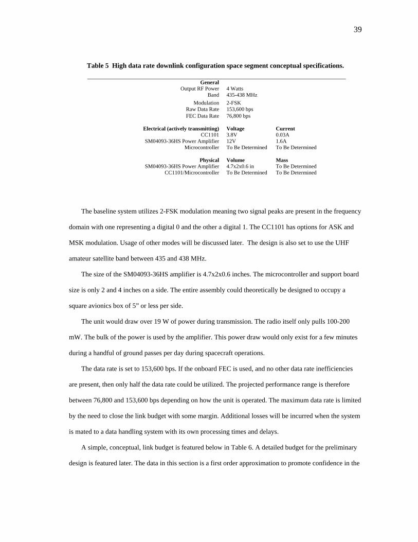
39
Table 5 High data rate downlink configuration space segment conceptual specifications.
General Output RF Power 4 Watts
Band 435-438 MHz Modulation 2-FSK
Raw Data Rate 153,600 bps FEC Data Rate 76,800 bps
Electrical (actively transmitting) Voltage Current
CC1101 3.8V 0.03A SM04093-36HS Power Amplifier 12V 1.6A
Microcontroller To Be Determined To Be Determined
Physical Volume Mass SM04093-36HS Power Amplifier 4.7x2x0.6 in To Be Determined
CC1101/Microcontroller To Be Determined To Be Determined
The baseline system utilizes 2-FSK modulation meaning two signal peaks are present in the frequency
domain with one representing a digital 0 and the other a digital 1. The CC1101 has options for ASK and
MSK modulation. Usage of other modes will be discussed later. The design is also set to use the UHF
amateur satellite band between 435 and 438 MHz.
The size of the SM04093-36HS amplifier is 4.7x2x0.6 inches. The microcontroller and support board
size is only 2 and 4 inches on a side. The entire assembly could theoretically be designed to occupy a
square avionics box of 5” or less per side.
The unit would draw over 19 W of power during transmission. The radio itself only pulls 100-200
mW. The bulk of the power is used by the amplifier. This power draw would only exist for a few minutes
during a handful of ground passes per day during spacecraft operations.
The data rate is set to 153,600 bps. If the onboard FEC is used, and no other data rate inefficiencies
are present, then only half the data rate could be utilized. The projected performance range is therefore
between 76,800 and 153,600 bps depending on how the unit is operated. The maximum data rate is limited
by the need to close the link budget with some margin. Additional losses will be incurred when the system
is mated to a data handling system with its own processing times and delays.
A simple, conceptual, link budget is featured below in Table 6. A detailed budget for the preliminary
design is featured later. The data in this section is a first order approximation to promote confidence in the
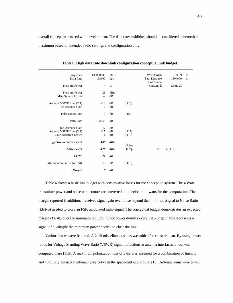
40
overall concept to proceed with development. The data rates exhibited should be considered a theoretical
maximum based on intended radio settings and configuration only.
Table 6 High data rate downlink configuration conceptual link budget.
Frequency 435000000 MHz Wavelength 0.69 m Data Rate 153600 bps Path Distance 1304000 m
Transmit Power 4 W Boltzmann constant k 1.38E-23
Transmit Power 36 dBm
Misc System Losses -2 dB
Antenna VSWR Loss (2:1) -0.5 dB [115] TX Antenna Gain 2 dB
Polarization Loss -3 dB [15]
Path Loss -147.5 dB
RX Antenna Gain 17 dB
Antenna VSWR Loss (2:1) -0.5 dB [115] LNA Insertion Losses -1 dB [116]
Effective Received Power -100 dBm
Noise Power -120 dBm Noise Temp 221 K [116]
Eb/No 21 dB
Minimum Required for FSK 15 dB [116]
Margin 6 dB
Table 6 shows a basic link budget with conservative losses for the conceptual system. The 4 Watt
transmitter power and noise temperature are converted into decibel milliwatts for the computation. The
margin reported is additional received signal gain over noise beyond the minimum Signal to Noise Ratio
(Eb/No) needed to close an FSK modulated radio signal. The conceptual budget demonstrates an expected
margin of 6 dB over the minimum required. Since power doubles every 3 dB of gain, this represents a
signal of quadruple the minimum power needed to close the link.
Various losses were featured. A 2 dB miscellaneous loss was added for conservatism. By using power
ratios for Voltage Standing Wave Ratio (VSWR) signal reflections at antenna interfaces, a loss was
computed there [115]. A maximum polarization loss of 3 dB was assumed for a combination of linearly
and circularly polarized antenna types between the spacecraft and ground [15]. Antenna gains were based
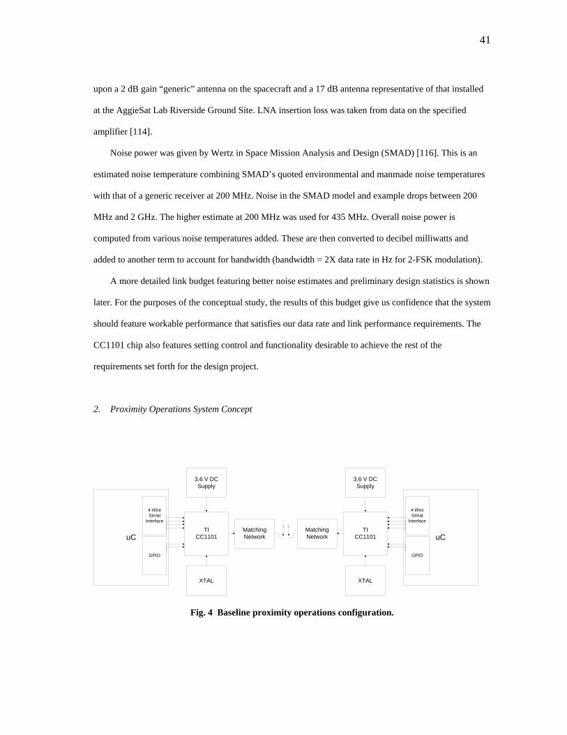
41
upon a 2 dB gain “generic” antenna on the spacecraft and a 17 dB antenna representative of that installed
at the AggieSat Lab Riverside Ground Site. LNA insertion loss was taken from data on the specified
amplifier [114].
Noise power was given by Wertz in Space Mission Analysis and Design (SMAD) [116]. This is an
estimated noise temperature combining SMAD’s quoted environmental and manmade noise temperatures
with that of a generic receiver at 200 MHz. Noise in the SMAD model and example drops between 200
MHz and 2 GHz. The higher estimate at 200 MHz was used for 435 MHz. Overall noise power is
computed from various noise temperatures added. These are then converted to decibel milliwatts and
added to another term to account for bandwidth (bandwidth = 2X data rate in Hz for 2-FSK modulation).
A more detailed link budget featuring better noise estimates and preliminary design statistics is shown
later. For the purposes of the conceptual study, the results of this budget give us confidence that the system
should feature workable performance that satisfies our data rate and link performance requirements. The
CC1101 chip also features setting control and functionality desirable to achieve the rest of the
requirements set forth for the design project.
2. Proximity Operations System Concept
uCTI
CC1101
3.6 V DC Supply
4 Wire Serial
Interface
GPIO
XTAL
Matching Network uC
TICC1101
3.6 V DC Supply
4 Wire Serial
Interface
GPIO
XTAL
Matching Network
Fig. 4 Baseline proximity operations configuration.
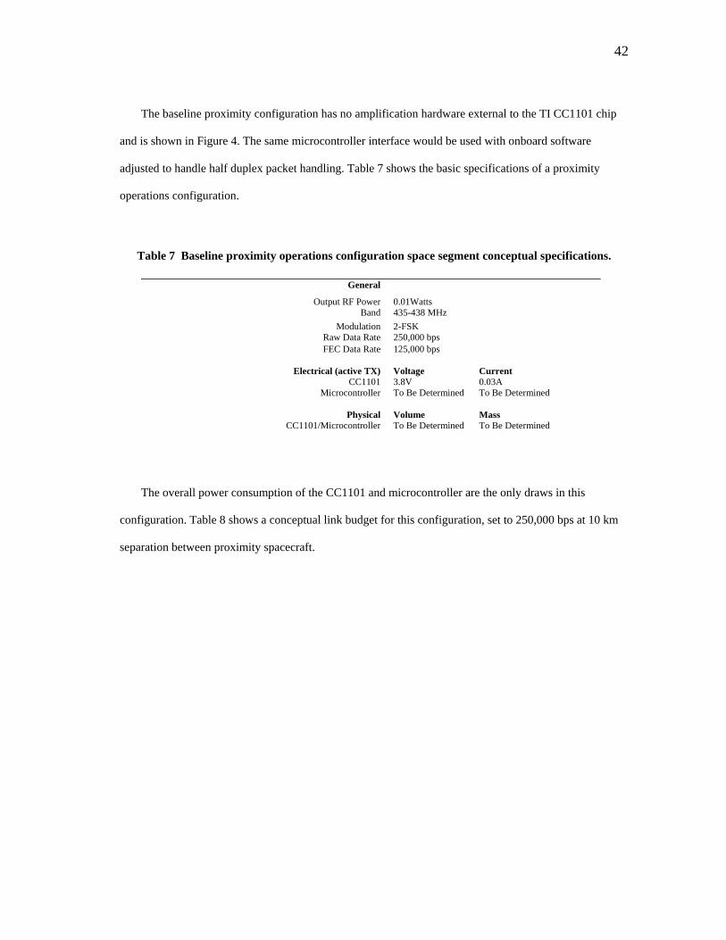
42
The baseline proximity configuration has no amplification hardware external to the TI CC1101 chip
and is shown in Figure 4. The same microcontroller interface would be used with onboard software
adjusted to handle half duplex packet handling. Table 7 shows the basic specifications of a proximity
operations configuration.
Table 7 Baseline proximity operations configuration space segment conceptual specifications.
General
Output RF Power 0.01Watts Band 435-438 MHz
Modulation 2-FSK Raw Data Rate 250,000 bps FEC Data Rate 125,000 bps
Electrical (active TX) Voltage Current
CC1101 3.8V 0.03A Microcontroller To Be Determined To Be Determined
Physical Volume Mass
CC1101/Microcontroller To Be Determined To Be Determined
The overall power consumption of the CC1101 and microcontroller are the only draws in this
configuration. Table 8 shows a conceptual link budget for this configuration, set to 250,000 bps at 10 km
separation between proximity spacecraft.
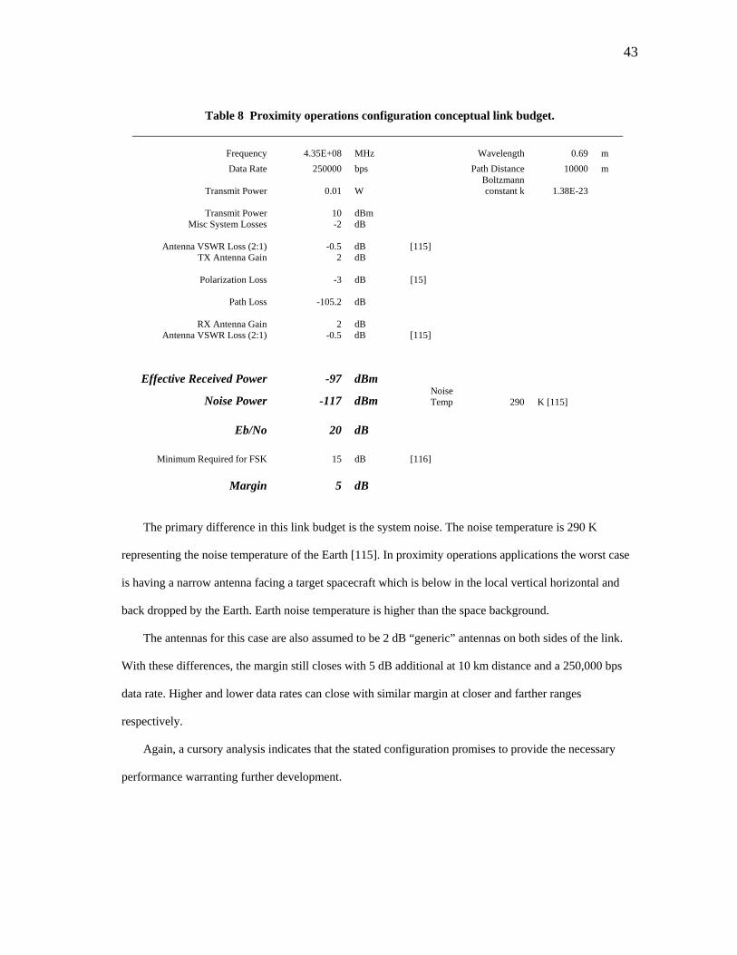
43
Table 8 Proximity operations configuration conceptual link budget.
Frequency 4.35E+08 MHz Wavelength 0.69 m Data Rate 250000 bps Path Distance 10000 m
Transmit Power 0.01 W Boltzmann constant k 1.38E-23
Transmit Power 10 dBm
Misc System Losses -2 dB
Antenna VSWR Loss (2:1) -0.5 dB [115] TX Antenna Gain 2 dB
Polarization Loss -3 dB [15]
Path Loss -105.2 dB
RX Antenna Gain 2 dB
Antenna VSWR Loss (2:1) -0.5 dB [115]
Effective Received Power -97 dBm
Noise Power -117 dBm Noise Temp 290 K [115]
Eb/No 20 dB
Minimum Required for FSK 15 dB [116]
Margin 5 dB
The primary difference in this link budget is the system noise. The noise temperature is 290 K
representing the noise temperature of the Earth [115]. In proximity operations applications the worst case
is having a narrow antenna facing a target spacecraft which is below in the local vertical horizontal and
back dropped by the Earth. Earth noise temperature is higher than the space background.
The antennas for this case are also assumed to be 2 dB “generic” antennas on both sides of the link.
With these differences, the margin still closes with 5 dB additional at 10 km distance and a 250,000 bps
data rate. Higher and lower data rates can close with similar margin at closer and farther ranges
respectively.
Again, a cursory analysis indicates that the stated configuration promises to provide the necessary
performance warranting further development.
44
D. Microcontroller Selection
A suitable microcontroller must be incorporated into the design that provides a SPI interface for
communication with CC1101 chips and an additional interface to allow users and spacecraft to
communicate with the completed radio device. The PIC18F4520 by Microchip Corporation was selected
for the thesis development.
The PIC18F4520 is part of a family of 8 bit microcontroller chips by Microchip featuring a mix of
peripheral and interface options [117]. The PIC18F4520 specifically features a separate SPI interface and
RS-232 Universal Synchronous/Asynchronous Transmitter (USART) interface. These devices are
inexpensive off the shelf components much like the CC1101 RFIC chip by Texas Instruments. The
USART interface can be configured as a synchronous or asynchronous interface. For the thesis design, an
asynchronous interface will be implemented. USART based serial communications are well established
and understood and featured as COM ports on most personal computers. This type of interface maximizes
the potential users of the device making the interface compatible with a wide variety of hardware.
The PIC18F4520 provides the required interfaces for the application and could be developed and
configured quickly because AggieSat Lab possesses the development tools required to work with it. This
decision was based on expediency since our focus is on a proof of concept for interfacing and utilizing the
RFIC chip. While expedient, the decision was made with confidence that the PIC18F4520 can perform in
a flight application.
The PIC18F4550, a closely related sibling of the PIC184520, formed the basis of the flight computer
on AggieSat2 flown in 2009 and 2010. That PIC18F4550 chip operated successfully for 230 days in the
LEO environment.
Besides thermal control, the primary concern for electronics operating in the LEO environment is
radiation tolerance. Radiation tolerance is the hardest to quantify and prepare for. The three primary
problems caused by radiation are Single Event Upsets (SEU), Single Event Latchups (SEL), and Single
Event Burnouts (SEB) [116]. Each occurs when an energetic particle passes through an electronic device
and deposits charge onboard.

45
SEU’s and SEL’s can be fixed on orbit. SEU’s are typically caused by a flipped bit in a logic device
caused by interaction with semiconductor material onboard. They usually do not cause operational
problems. The greatest problem they can cause is to corrupt stored information such as a program in
onboard memory because bits are changed. This can be combated by logic checks to determine if
corruption has occurred and reloading code from a separate memory location.
SEL’s occur when the interaction causes a change in the device that hangs up or freezes the electrical
operation [116]. SEL’s can be solved by resetting power to a device. It is possible that AggieSat2’s flight
computer experienced this type of malfunction since the computer was typically reset automatically on a
daily basis. SEL’s would be subsequently flushed. Since satellite downlink radio operation occurs for a
few minutes at a time one to two times per day per ground site, and since transmit operation with an
amplifier is power intensive, an RFIC radio unit would be power cycled frequently for standard
operational concerns. As an added benefit these resets would mitigate SEL effects to the microcontroller.
The most dangerous event upset is the SEB where physical damage occurs to the device because of
the interaction with environmental radiation [116]. Often times a short and subsequent burnout of the
device can occur when interacting with high energy particles. The PIC18F4550 onboard AggieSat2 did not
encounter this kind of failure during its 230-day flight. During AggieSat2 the flight computer was
contained inside of two stainless steel plates that served as mounting “racks” for the onboard electronics,
and the overall aluminum exterior structure. The spacecraft flew through orbital altitudes from 332 km
down to atmospheric interface during the 230-day flight.
While more investigation will be needed for the CC1101 RFIC chip itself, the PIC18 series chips are
usable in a LEO environment and radiation performance was not considered detrimental for proof of
concept work on the RFIC system.
While considering microcontroller solutions it was found that Intel 8051 architecture based
microcontrollers are prolific in space applications and a have a large information base on radiation
performance [118]. The 8051 architecture is available from many commercial vendors, development tools
are available, and the chipset has been developed into enhanced radiation tolerant versions [119].
46
Atmel, who also manufactures some of the alternative RFIC chips studied, also offers a line of
aerospace grade, radiation tolerant controller, processor, and memory components [120].
Atmel’s specific microcontroller offering is the Atmel 80C32E 8 bit device [121]. In many ways this
device is similar in scale and capability to the PIC microcontrollers. One disadvantage is that the Atmel
80C32E does not feature onboard Read Only Memory (ROM). A radiation tolerant ROM IC would have
to be added to the design by anyone attempting to use it.
User’s that are interested can incorporate these devices into the RFIC design if radiation robustness
was desired for the interface and control segment of the radio. Information on the Intel 8051 and Atmel
chips is easily found and commercially available.
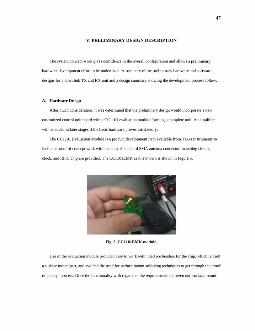
47
V. PRELIMINARY DESIGN DESCRIPTION
The system concept work gives confidence in the overall configuration and allows a preliminary
hardware development effort to be undertaken. A summary of the preliminary hardware and software
designs for a downlink TX and RX unit and a design summary showing the development process follow.
A. Hardware Design
After much consideration, it was determined that the preliminary design would incorporate a new
customized control unit board with a CC1101 evaluation module forming a complete unit. An amplifier
will be added in later stages if the basic hardware proves satisfactory.
The CC1101 Evaluation Module is a product development item available from Texas Instruments to
facilitate proof of concept work with the chip. A standard SMA antenna connector, matching circuit,
clock, and RFIC chip are provided. The CC1101EMK as it is known is shown in Figure 5.
Fig. 5 CC1101EMK module.
Use of the evaluation module provided easy to work with interface headers for the chip, which is itself
a surface mount part, and avoided the need for surface mount soldering techniques to get through the proof
of concept process. Once the functionality with regards to the requirements is proven out, surface mount
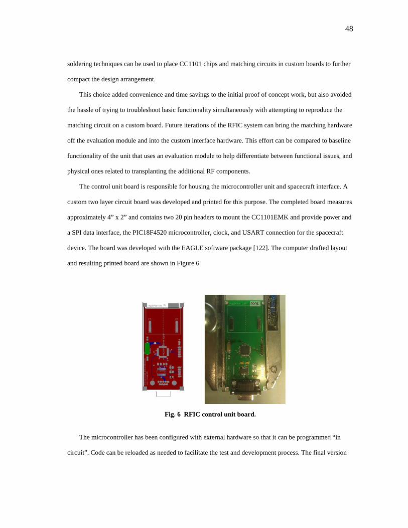
48
soldering techniques can be used to place CC1101 chips and matching circuits in custom boards to further
compact the design arrangement.
This choice added convenience and time savings to the initial proof of concept work, but also avoided
the hassle of trying to troubleshoot basic functionality simultaneously with attempting to reproduce the
matching circuit on a custom board. Future iterations of the RFIC system can bring the matching hardware
off the evaluation module and into the custom interface hardware. This effort can be compared to baseline
functionality of the unit that uses an evaluation module to help differentiate between functional issues, and
physical ones related to transplanting the additional RF components.
The control unit board is responsible for housing the microcontroller unit and spacecraft interface. A
custom two layer circuit board was developed and printed for this purpose. The completed board measures
approximately 4” x 2” and contains two 20 pin headers to mount the CC1101EMK and provide power and
a SPI data interface, the PIC18F4520 microcontroller, clock, and USART connection for the spacecraft
device. The board was developed with the EAGLE software package [122]. The computer drafted layout
and resulting printed board are shown in Figure 6.
Fig. 6 RFIC control unit board.
The microcontroller has been configured with external hardware so that it can be programmed “in
circuit”. Code can be reloaded as needed to facilitate the test and development process. The final version
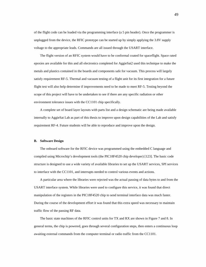
49
of the flight code can be loaded via the programming interface (a 5 pin header). Once the programmer is
unplugged from the device, the RFIC prototype can be started up by simply applying the 3.8V supply
voltage to the appropriate leads. Commands are all issued through the USART interface.
The flight version of an RFIC system would have to be conformal coated for spaceflight. Space rated
epoxies are available for this and all electronics completed for AggieSat2 used this technique to make the
metals and plastics contained in the boards and components safe for vacuum. This process will largely
satisfy requirement RF-5. Thermal and vacuum testing of a flight unit for its first integration for a future
flight test will also help determine if improvements need to be made to meet RF-5. Testing beyond the
scope of this project will have to be undertaken to see if there are any specific radiation or other
environment tolerance issues with the CC1101 chip specifically.
A complete set of board layer layouts with parts list and a design schematic are being made available
internally to AggieSat Lab as part of this thesis to improve upon design capabilities of the Lab and satisfy
requirement RF-4. Future students will be able to reproduce and improve upon the design.
B. Software Design
The onboard software for the RFIC device was programmed using the embedded C language and
compiled using Microchip’s development tools (the PIC18F4520 chip developer) [123]. The basic code
structure is designed to use a wide variety of available libraries to set up the USART services, SPI services
to interface with the CC1101, and interrupts needed to control various events and actions.
A particular area where the libraries were rejected was the actual passing of data bytes to and from the
USART interface system. While libraries were used to configure this service, it was found that direct
manipulation of the registers in the PIC18F4520 chip to send terminal interface data was much faster.
During the course of the development effort it was found that this extra speed was necessary to maintain
traffic flow of the passing RF data.
The basic state machines of the RFIC control units for TX and RX are shown in Figure 7 and 8. In
general terms, the chip is powered, goes through several configuration steps, then enters a continuous loop
awaiting external commands from the computer terminal or radio traffic from the CC1101.
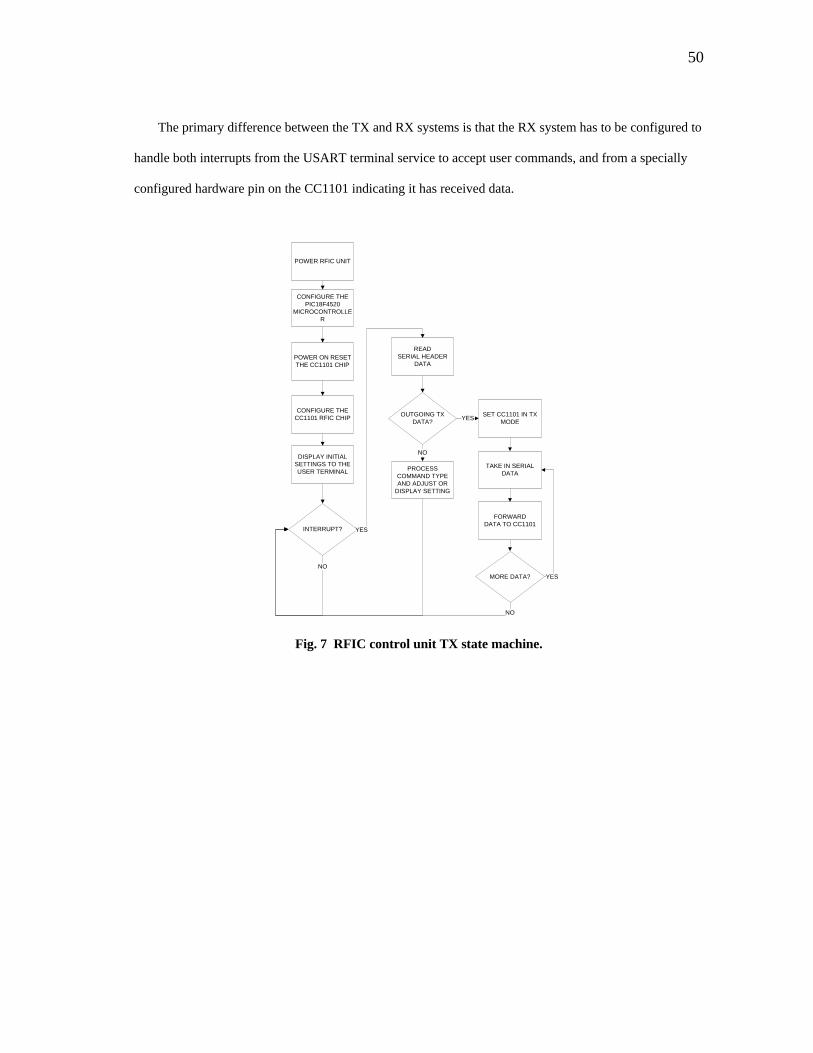
50
The primary difference between the TX and RX systems is that the RX system has to be configured to
handle both interrupts from the USART terminal service to accept user commands, and from a specially
configured hardware pin on the CC1101 indicating it has received data.
POWER RFIC UNIT
CONFIGURE THE PIC18F4520
MICROCONTROLLER
CONFIGURE THE CC1101 RFIC CHIP
POWER ON RESET THE CC1101 CHIP
DISPLAY INITIAL SETTINGS TO THE USER TERMINAL
INTERRUPT?
NO
READSERIAL HEADER
DATA
OUTGOING TX DATA?
PROCESS COMMAND TYPE AND ADJUST OR
DISPLAY SETTING
NO
YES
TAKE IN SERIAL DATA
FORWARDDATA TO CC1101
YES
MORE DATA? YES
NO
SET CC1101 IN TX MODE
Fig. 7 RFIC control unit TX state machine.
51
Fig. 8 RFIC control unit RX state machine.
The interrupt handler system onboard the microcontroller is governed by its own subroutine. This
subroutine manages data flow in and out of the CC1101 data buffers when called upon to forward or
receive data.
As explained before, the CC1101 can only handle a maximum of 64 bytes in its onboard memory
buffers. A series of logical checks and processes are used to manage the traffic flow and refill or empty
additional bytes from the CC1101 as able to prevent traffic jams. Refilling or emptying tasks are
programmed into the system depending on if the system is configured for TX or RX respectively. It is
important to note that in all cases, the CC1101 supporting hardware and control unit are comprised of
exactly the same physical hardware regardless of if the unit is to act as a transmitter, receiver, or half
duplex proximity operations system. The deciding factor in functionality is simply which software build
has been loaded into the microcontroller.
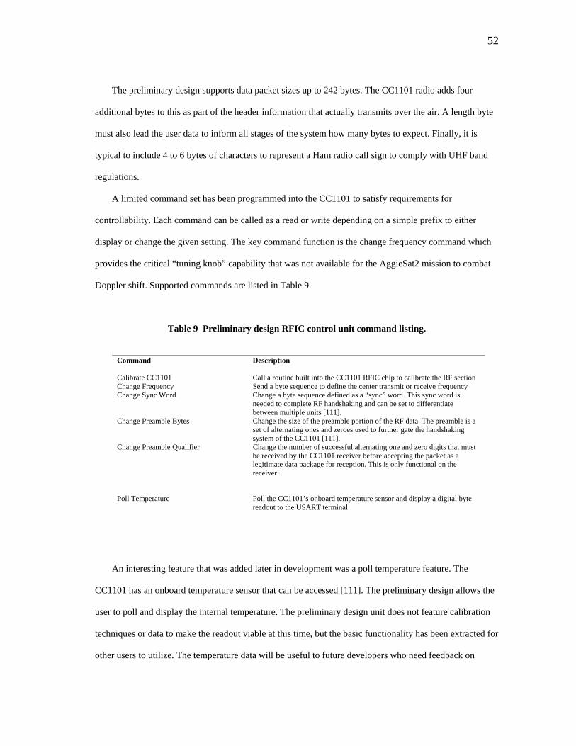
52
The preliminary design supports data packet sizes up to 242 bytes. The CC1101 radio adds four
additional bytes to this as part of the header information that actually transmits over the air. A length byte
must also lead the user data to inform all stages of the system how many bytes to expect. Finally, it is
typical to include 4 to 6 bytes of characters to represent a Ham radio call sign to comply with UHF band
regulations.
A limited command set has been programmed into the CC1101 to satisfy requirements for
controllability. Each command can be called as a read or write depending on a simple prefix to either
display or change the given setting. The key command function is the change frequency command which
provides the critical “tuning knob” capability that was not available for the AggieSat2 mission to combat
Doppler shift. Supported commands are listed in Table 9.
Table 9 Preliminary design RFIC control unit command listing.
Command Description Calibrate CC1101 Call a routine built into the CC1101 RFIC chip to calibrate the RF section Change Frequency Send a byte sequence to define the center transmit or receive frequency Change Sync Word Change a byte sequence defined as a “sync” word. This sync word is
needed to complete RF handshaking and can be set to differentiate between multiple units [111].
Change Preamble Bytes Change the size of the preamble portion of the RF data. The preamble is a set of alternating ones and zeroes used to further gate the handshaking system of the CC1101 [111].
Change Preamble Qualifier Change the number of successful alternating one and zero digits that must be received by the CC1101 receiver before accepting the packet as a legitimate data package for reception. This is only functional on the receiver.
Poll Temperature Poll the CC1101’s onboard temperature sensor and display a digital byte readout to the USART terminal
An interesting feature that was added later in development was a poll temperature feature. The
CC1101 has an onboard temperature sensor that can be accessed [111]. The preliminary design allows the
user to poll and display the internal temperature. The preliminary design unit does not feature calibration
techniques or data to make the readout viable at this time, but the basic functionality has been extracted for
other users to utilize. The temperature data will be useful to future developers who need feedback on

53
temperature for environmental factors that are affecting operation, or for general state of health data
collection on a spacecraft.
Other commands and functionality could easily be added to this system or another RFIC system with
a sufficiently capable microcontroller chassis. The functionality that has been included is intended to meet
the basic requirements needed to prove the concept and demonstrate the utility of the system. More
detailed options are left to users with specific operational needs.
The clocks and timing settings onboard the entire system have been set to provide a 256 kbps USART
data rate and a 153.6 kbps over the air transmission rate for the RF section. The higher interface rate was
selected to ensure the USART data arrives fast enough to allow the PIC18F4520 chip to sample at a rate
much faster than the CC1101 to help with detection of packets and changes in radio state.
Analysis in later sections will evaluate the useful data rate and performance based upon both
analytical analysis and test data taking into account additional overhead present in the data stream.
C. Development Summary
The conceptual trade studies, design and initial background research were completed between
September and November of 2010. The majority of hardware development for the unit described in
Section V took place between November 2010 and May 2011.
The first step taken was to order development kits for the CC1101 from Texas Instruments. These
development kits accept the CC1101EMK modules and provide an exploratory interface for new users.
The board and accompanying software was used to quickly learn and operate the CC1101’s basic memory
registers that controlled all settings and buffers.
A parallel effort was undertaken in November of 2010 to learn PIC microcontroller programming.
Simple tutorials and basic programs were developed to learn how to compile and run project code,
manipulate signal pins, and eventually use the interface services for SPI and USART. The first successful
PIC code of any kind was successfully programmed on November 16th.
A basic breadboard was initially developed to run tutorial programs. This breadboard was built up
over time into the first RFIC project transmitter between November and December. The breadboard in the
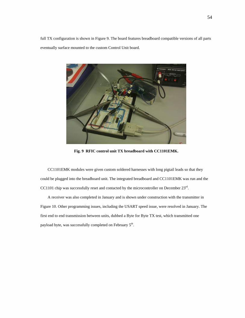
54
full TX configuration is shown in Figure 9. The board features breadboard compatible versions of all parts
eventually surface mounted to the custom Control Unit board.
Fig. 9 RFIC control unit TX breadboard with CC1101EMK.
CC1101EMK modules were given custom soldered harnesses with long pigtail leads so that they
could be plugged into the breadboard unit. The integrated breadboard and CC1101EMK was run and the
CC1101 chip was successfully reset and contacted by the microcontroller on December 23rd.
A receiver was also completed in January and is shown under construction with the transmitter in
Figure 10. Other programming issues, including the USART speed issue, were resolved in January. The
first end to end transmission between units, dubbed a Byte for Byte TX test, which transmitted one
payload byte, was successfully completed on February 5th.

55
Fig. 10 Work in progress RFIC breadboard receiver (foreground) and RFIC breadboard
transmitter (background).
An expanded packet handler code was the priority in February 2011. A 64 byte packet handler code
was operational on February 20th, and the current 243 byte handler was finished on March 12th. This
milestone and the functionality demonstrated previously by the breadboard units justified development of
a printed board for the control unit.
The EAGLE layout was completed in early April and the first two complete test units were fully
integrated with CC1101EMK modules by April 23rd and May 7th for the transmitter and receiver
respectively. An example of a completed unit with a CC1101EMK module is shown in Figure 11.
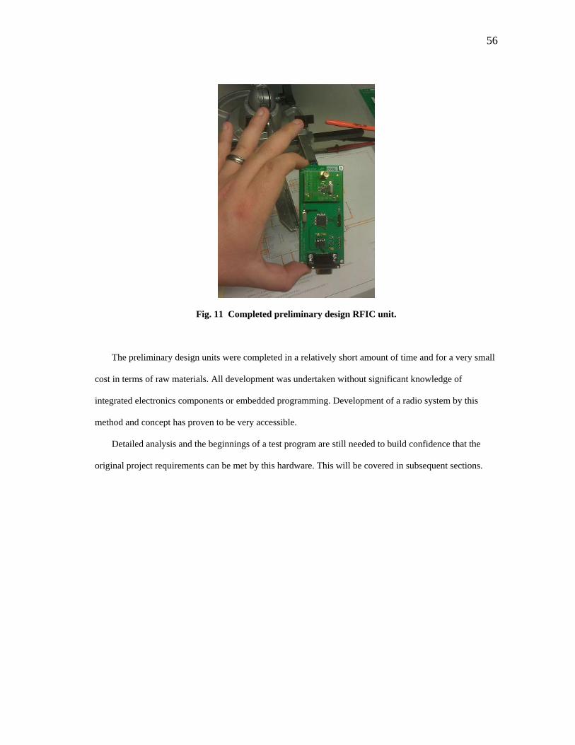
56
Fig. 11 Completed preliminary design RFIC unit.
The preliminary design units were completed in a relatively short amount of time and for a very small
cost in terms of raw materials. All development was undertaken without significant knowledge of
integrated electronics components or embedded programming. Development of a radio system by this
method and concept has proven to be very accessible.
Detailed analysis and the beginnings of a test program are still needed to build confidence that the
original project requirements can be met by this hardware. This will be covered in subsequent sections.

57
VI. VERIFICATION PLAN
A verification plan is presented to define analysis and testing tasks that are both part of this thesis and
future work. An overall hardware design has been implemented and shown to be functional on a basic
level. All requirements regarding the basic goals for the thesis, including the documentation and design
capture goals have some representation.
Key performance requirements are described by RF-6 through RF-9. Frequency agility, data through
put and signal power considerations must be verified against requirements. These requirements represent
the primary motivation of this work. This will be done in three phases.
Phase 1 is analysis verification. A more detailed link analysis, data rate analysis, and frequency
control analysis will be conducted to help define some testing parameters and serve as a first initial
performance estimate. This exercise will also give some additional confidence in expected performance
based on standard analysis methods and assumptions about radio links.
Phase 2 is the initial test verification. Tests will be defined to understand the basic signaling and
timing of the device both for the user terminal interface and the RF interface, as well as statistical testing.
Statistical testing will allow data to be taken on data success rates versus both signal powers and frequency
offsets. This basic testing is fundamental to understanding the device, its expected performance, and will
give good indications as to whether or not the RFIC concept is worth pursuing. This phase will be the
focus of the results featured in the thesis itself.
Phase 3 will feature future work intended for preparing a prototype unit for a flight test, meeting
environmental requirements, and additional testing needed based on preliminary thesis results. The
suggestions for these tests are featured here, but the execution and results of these tests will be part of
future development.
Table 10 summarizes the preliminary verification plan. Each of the verification phases is shown in
relation to both the original requirements and “design verification” steps that were addressed either by a
specific design choice or documentation action. Each relevant testing item will be summarized.
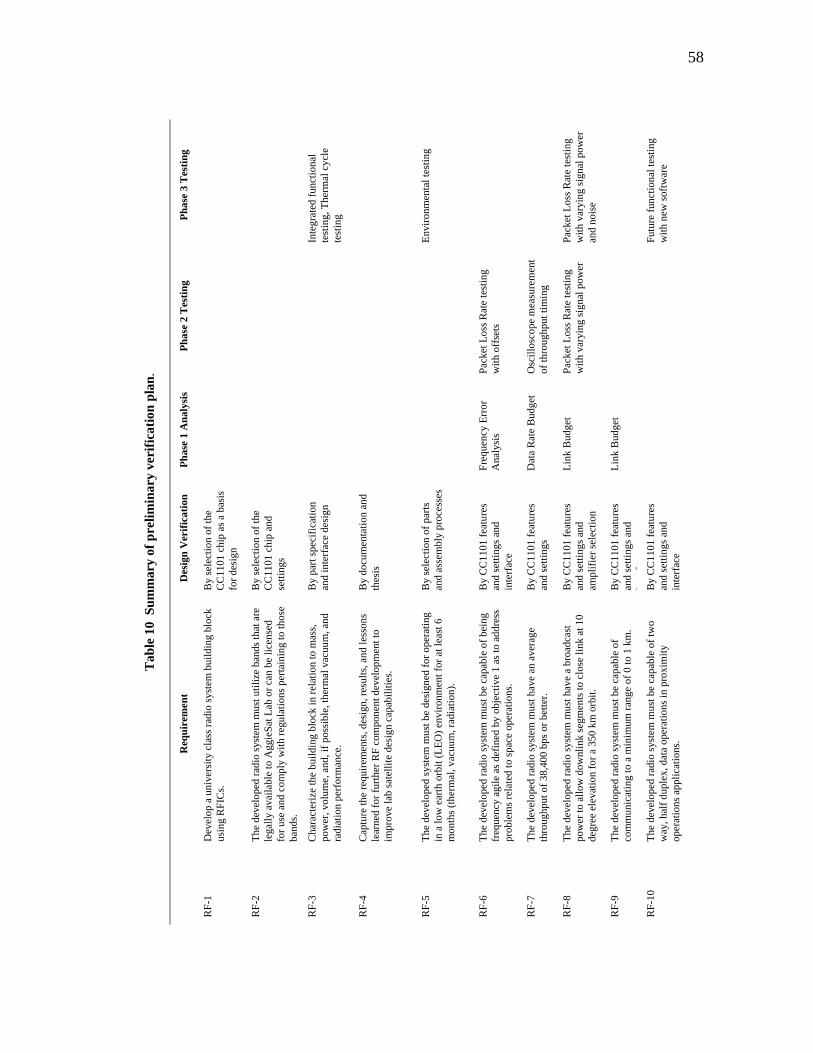
58
Tab
le 1
0 S
umm
ary
of p
relim
inar
y ve
rific
atio
n pl
an.
Ph
ase
3 T
estin
g
Inte
grat
ed fu
nctio
nal
test
ing,
The
rmal
cyc
le
test
ing
Envi
ronm
enta
l tes
ting
Pack
et L
oss R
ate
test
ing
with
var
ying
sign
al p
ower
an
d no
ise
Futu
re fu
nctio
nal t
estin
g w
ith n
ew so
ftwar
e
Phas
e 2
Tes
ting
Pack
et L
oss R
ate
test
ing
with
off
sets
Osc
illos
cope
mea
sure
men
t of
thro
ughp
ut ti
min
g
Pack
et L
oss R
ate
test
ing
with
var
ying
sign
al p
ower
Phas
e 1
Ana
lysi
s
Freq
uenc
y Er
ror
Ana
lysi
s
Dat
a R
ate
Bud
get
Link
Bud
get
Link
Bud
get
Des
ign
Ver
ifica
tion
By
sele
ctio
n of
the
CC
1101
chi
p as
a b
asis
fo
r des
ign
By
sele
ctio
n of
the
CC
1101
chi
p an
d se
tting
s
By
part
spec
ifica
tion
and
inte
rfac
e de
sign
By
docu
men
tatio
n an
d th
esis
By
sele
ctio
n of
par
ts
and
asse
mbl
y pr
oces
ses
By
CC
1101
feat
ures
an
d se
tting
s and
in
terf
ace
By
CC
1101
feat
ures
an
d se
tting
s B
y C
C11
01 fe
atur
es
and
setti
ngs a
nd
ampl
ifier
sele
ctio
n
By
CC
1101
feat
ures
an
d se
tting
s and
i
fB
y C
C11
01 fe
atur
es
and
setti
ngs a
nd
inte
rfac
e
Req
uire
men
t
Dev
elop
a u
nive
rsity
cla
ss ra
dio
syst
em b
uild
ing
bloc
k us
ing
RFI
Cs.
The
deve
lope
d ra
dio
syst
em m
ust u
tiliz
e ba
nds t
hat a
re
lega
lly a
vaila
ble
to A
ggie
Sat L
ab o
r can
be
licen
sed
for u
se a
nd c
ompl
y w
ith re
gula
tions
per
tain
ing
to th
ose
band
s. C
hara
cter
ize
the
build
ing
bloc
k in
rela
tion
to m
ass,
pow
er, v
olum
e, a
nd, i
f pos
sibl
e, th
erm
al v
acuu
m, a
nd
radi
atio
n pe
rfor
man
ce.
Cap
ture
the
requ
irem
ents
, des
ign,
resu
lts, a
nd le
sson
s le
arne
d fo
r fur
ther
RF
com
pone
nt d
evel
opm
ent t
o im
prov
e la
b sa
telli
te d
esig
n ca
pabi
litie
s.
The
deve
lope
d sy
stem
mus
t be
desi
gned
for o
pera
ting
in a
low
ear
th o
rbit
(LEO
) env
ironm
ent f
or a
t lea
st 6
m
onth
s (th
erm
al, v
acuu
m, r
adia
tion)
.
The
deve
lope
d ra
dio
syst
em m
ust b
e ca
pabl
e of
bei
ng
freq
uenc
y ag
ile a
s def
ined
by
obje
ctiv
e 1
as to
add
ress
pr
oble
ms r
elat
ed to
spac
e op
erat
ions
. Th
e de
velo
ped
radi
o sy
stem
mus
t hav
e an
ave
rage
th
roug
hput
of 3
8,40
0 bp
s or b
ette
r. Th
e de
velo
ped
radi
o sy
stem
mus
t hav
e a
broa
dcas
t po
wer
to a
llow
dow
nlin
k se
gmen
ts to
clo
se li
nk a
t 10
degr
ee e
leva
tion
for a
350
km
orb
it.
The
deve
lope
d ra
dio
syst
em m
ust b
e ca
pabl
e of
co
mm
unic
atin
g to
a m
inim
um ra
nge
of 0
to 1
km
. Th
e de
velo
ped
radi
o sy
stem
mus
t be
capa
ble
of tw
o w
ay, h
alf d
uple
x, d
ata
oper
atio
ns in
pro
xim
ity
oper
atio
ns a
pplic
atio
ns.
RF-
1
RF-
2
RF-
3
RF-
4
RF-
5
RF-
6
RF-
7
RF-
8
RF-
9
RF-
10
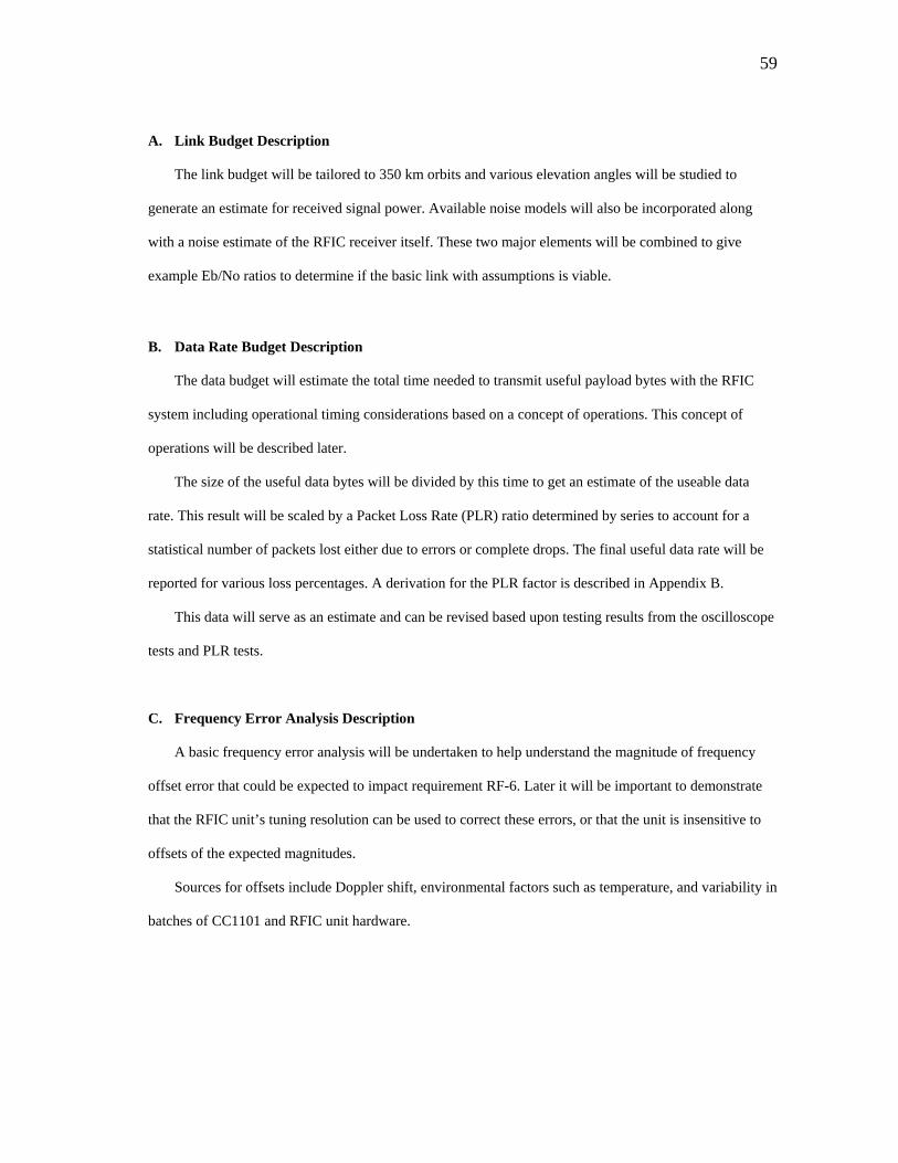
59
A. Link Budget Description
The link budget will be tailored to 350 km orbits and various elevation angles will be studied to
generate an estimate for received signal power. Available noise models will also be incorporated along
with a noise estimate of the RFIC receiver itself. These two major elements will be combined to give
example Eb/No ratios to determine if the basic link with assumptions is viable.
B. Data Rate Budget Description
The data budget will estimate the total time needed to transmit useful payload bytes with the RFIC
system including operational timing considerations based on a concept of operations. This concept of
operations will be described later.
The size of the useful data bytes will be divided by this time to get an estimate of the useable data
rate. This result will be scaled by a Packet Loss Rate (PLR) ratio determined by series to account for a
statistical number of packets lost either due to errors or complete drops. The final useful data rate will be
reported for various loss percentages. A derivation for the PLR factor is described in Appendix B.
This data will serve as an estimate and can be revised based upon testing results from the oscilloscope
tests and PLR tests.
C. Frequency Error Analysis Description
A basic frequency error analysis will be undertaken to help understand the magnitude of frequency
offset error that could be expected to impact requirement RF-6. Later it will be important to demonstrate
that the RFIC unit’s tuning resolution can be used to correct these errors, or that the unit is insensitive to
offsets of the expected magnitudes.
Sources for offsets include Doppler shift, environmental factors such as temperature, and variability in
batches of CC1101 and RFIC unit hardware.
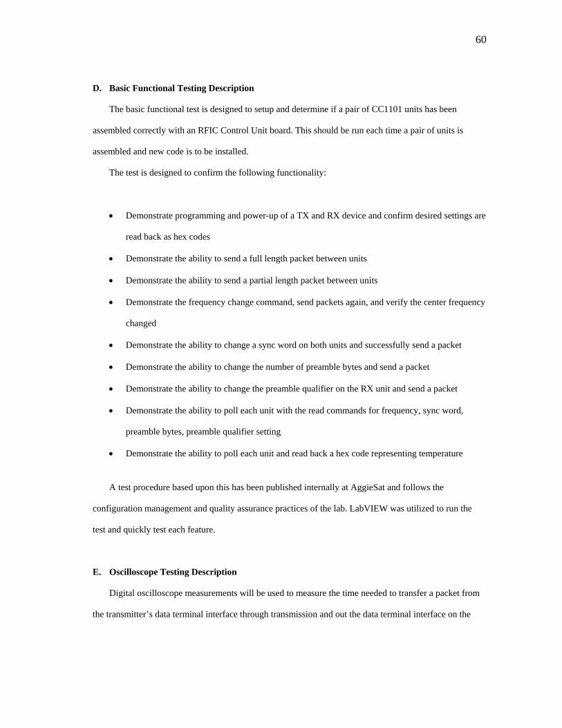
60
D. Basic Functional Testing Description
The basic functional test is designed to setup and determine if a pair of CC1101 units has been
assembled correctly with an RFIC Control Unit board. This should be run each time a pair of units is
assembled and new code is to be installed.
The test is designed to confirm the following functionality:
• Demonstrate programming and power-up of a TX and RX device and confirm desired settings are
read back as hex codes
• Demonstrate the ability to send a full length packet between units
• Demonstrate the ability to send a partial length packet between units
• Demonstrate the frequency change command, send packets again, and verify the center frequency
changed
• Demonstrate the ability to change a sync word on both units and successfully send a packet
• Demonstrate the ability to change the number of preamble bytes and send a packet
• Demonstrate the ability to change the preamble qualifier on the RX unit and send a packet
• Demonstrate the ability to poll each unit with the read commands for frequency, sync word,
preamble bytes, preamble qualifier setting
• Demonstrate the ability to poll each unit and read back a hex code representing temperature
A test procedure based upon this has been published internally at AggieSat and follows the
configuration management and quality assurance practices of the lab. LabVIEW was utilized to run the
test and quickly test each feature.
E. Oscilloscope Testing Description
Digital oscilloscope measurements will be used to measure the time needed to transfer a packet from
the transmitter’s data terminal interface through transmission and out the data terminal interface on the

61
receiver. This time information can be used to improve the data rate budget for the designed system and
will represent the basic throughput per packet of the system.
For each run the transmitter and receiver should be configured to operate normally with full size
packets being transferred.
The scope can measure data in the time domain between the transmitter data terminal and the receiver
data terminal. Figure 12 shows this arrangement and an example scope output for breadboard prototype
units.
TX CONROL UNIT RX CONROL UNIT
CC1101 MODULE
CC1101 MODULE
TRANSMITTER DATA TERMINAL
DEVICERS232 INPUT
RECEIVERDATA TERMINAL
DEVICERS232 OUTPUT
DIGITAL OSCILLOSCOPE
CHANNEL 1 CHANNEL 2
CARRIERSIGNAL
Fig. 12 Basic oscilloscope testing arrangement.
F. Packet Loss Rate Testing Description
PLR testing is designed to show data rate performance for given conditions. Each type of test involves
sending many generated packets, end to end, from the transmitter to the receiver and counting total packets
sent, total received, and total number of received that feature bit errors for a given time. The test will be
repeated for various conditions to build some basic statistical data.
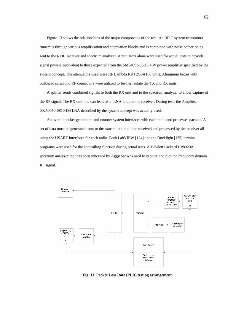
62
Figure 13 shows the relationships of the major components of the test. An RFIC system transmitter
transmits through various amplification and attenuation blocks and is combined with noise before being
sent to the RFIC receiver and spectrum analyzer. Attenuators alone were used for actual tests to provide
signal powers equivalent to those expected from the SM04093-36HS 4 W power amplifier specified by the
system concept. The attenuators used were RF Lambda RKT2G3A100 units. Aluminum boxes with
bulkhead serial and RF connectors were utilized to further isolate the TX and RX units.
A splitter sends combined signals to both the RX unit and to the spectrum analyzer to allow capture of
the RF signal. The RX unit line can feature an LNA to quiet the receiver. During tests the Amplitech
00250050-0810-D4 LNA described by the system concept was actually used.
An overall packet generation and counter system interfaces with each radio and processes packets. A
set of data must be generated, sent to the transmitter, and then received and processed by the receiver all
using the USART interfaces for each radio. Both LabVIEW [124] and the Docklight [125] terminal
programs were used for the controlling function during actual tests. A Hewlett Packard HP8920A
spectrum analyzer that has been inherited by AggieSat was used to capture and plot the frequency domain
RF signal.
Fig. 13 Packet Loss Rate (PLR) testing arrangement.
63
Fig. 14 Packet Loss Rate (PLR) testing arrangement implementation.
Figure 14 shows the actual implementation of the PLR test. In Figure 14, starting on the top shelf left
to right is the HP8920A spectrum analyzer. On the table in the background left to right is an NS-3 noise
generator by Applied Instruments, the RX unit in an aluminum box, the RX and LNA DC power supplies,
the TX unit in an aluminum box, and the TX power supply. In the foreground on the white support board
are the two RFLT2W0002GS signal combiner/splitters by RF Lambda, and both attenuators with the
associated RF cables needed to connect the devices. The LNA itself is not pictured.
Figure 15 shows detail of an RFIC unit with the aluminum boxes for testing.
a) Prior to integration b) Integrated unit
Fig. 15 RFIC unit with aluminum box for PLR test.
64
Two major PLR test categories are desired.
1. Signal Level PLR Tests
Signal level PLR tests will be performed at various attenuator settings to show determine if the
receiver unit is sensitive to transmissions from the TX unit, and what the packet loss statistics are. Desired
signal levels are those expected to be received from the RFIC unit and SM04093-36HS amplifier from
space in a 350 km orbit between 10 and 90 degrees elevation above the horizon. The link budget will help
determine a range of signal levels to simulate this.
Other settings of interest are the preamble qualifier setting of the CC1101 units and whether or not an
LNA is used on the receiver.
The preamble qualifier settings can be set so that the entire preamble or part of the preamble must be
received successfully to let in a new packet. Any incoming packets are still gated by the sync word. It was
determined during early functional testing that requiring a full reception of the preamble prevented a lot of
otherwise useful packets from getting through. The original qualifier required 8 successful alternating
preamble bit transitions to make it through, this was cut to 4 bits in the final design. This configuration
was tested throughout the results in the thesis. Further variation on this parameter may be desirable in
future testing, but setting the qualifier to zero is not recommended, as this was observed to allow many
false packet receptions.
Early on it was also found that reception at the expected signal levels was not possible without an
LNA similar to the Amplitech 00250050-0810-D4. This LNA has 25 dB of gain [114]. A similar amplifier
would need to be part of standard ground station equipment for an operational system. This is not
considered to be a problem since amplifier stages are common in ground sites. The drastic difference in
quieting of the RX unit electronics by the amplifier meant that all result cases feature the amplifier.
2. Offset PLR Tests
A second major set PLR tests must vary the programmed center band of the RFIC transmitter while
holding the setting of the receiver constant to determine if and when the signal is degraded or lost in the

65
presence of a frequency mismatch. This shall be done in kilohertz steps on the order of magnitude of
Doppler and other shifts to see first if the frequency can be controlled, and second if the unit is tolerant to
the effect.
The frequency analysis will help bound range and steps desired for this test. Functionally the rest of
the PLR test will be the same as that for the signal level tests. The units will be cycled in the new
frequency state and packet receptions and drops will be recorded.
G. Phase 3 Testing Description
Phase 3 features expanded testing with intent to eventually fly the device. This includes
environmental testing (thermal and vacuum) typical to spacecraft hardware preparation, additional thermal
cycle testing if more resolution is desired on frequency controllability, and integrated functional testing
with some future spacecraft Command and Data Handling (CDH) system to refine the first application.
Phase 3 can also capture future work required based on the experiences of the Phase 2 testing. One
particular area identified is to complete PLR tests with the simulated noise in the system. It was found that
while the capability to create noise was available, the low signal levels required prevented measurement to
confirm noise was set properly with the available testing equipment. Spectrum analysis equipment with
better sensitivity and resolution for very low power signals is desired and is being sought with AggieSat’s
NASA partners. This will be re-visited later.
The analysis and testing planned for the RFIC thesis project covers the major functional requirements
that motivate the development of the concept. The existing testing will give a good idea to any potential
user if this type of radio system is even worth developing. The tests planned for future development fit in
well with the detailed work that will be required when an organization is ready to commit to proving that
an RFIC system can be made ready for an actual flight test and integrated with a partner CDH system.

66
VII. VERIFICATION ANALYSIS
A. Link Analysis
The link analysis is divided into a received carrier power segment and a noise power segment. The
received carrier power segment will evaluate the transmitted signal power and summation of losses as the
radio wave travels from space to ground. The noise segment will compare noise models and add in an
estimate for the internal noise power at the receiver. Both will be compared to judge estimated link
performance.
All signal powers are treated in decibel milliwatts (dBm). Losses and gains at intermediate steps that
simply represent the ratio of the output to the input are represented by decibels (dB). They apply to any
value that they are added against. If a 3 dB loss occurs to an original signal of 6 dBm power the result will
be 6 dBm – 3 dB, resulting in a final signal power of 3 dBm.
All analyses are based on the assumption of a spacecraft in a 350 km circular orbit above the Earth.
1. Received Carrier Power
Due to the low output power of the CC1101 RF chip an external amplifier is needed. Powers from 1
to 4 Watts have been considered. A SM04093-36HS 4 Watt amplifier from Stealth Microwave has been
assumed for the system [113].
A Voltage Standing Wave Ratios (VSWR) of 2 is assumed at reflection points for antennas in the
system. This is a conservative estimate assuming that antennas are not perfectly matched (VSWR of 1).
0.5 dB loss is assumed due to each antenna because of this reflection [115].
A 2 dB gain antenna is assumed on the spacecraft.
A 3 dB polarization loss is assumed to represent the maximum possible loss between a circularly
polarized and linearly polarized antenna. One circularly polarized antenna in the link in combination with
a linearly polarized one guarantees a finite maximum loss of 3 dB [15].
Path loss is given by the Equation (1) [116]:

67
2
4⎟⎠⎞
⎜⎝⎛=
SLPath π
λ (1)
λ is the wavelength of the signal (~70cm in this case for transmit frequencies between 435 and 438 MHz
on the amateur satellite band). S is the range of the spacecraft. This value is the slant range to the
spacecraft at a given elevation for a 350 km orbit.
A receiver antenna gain of 17 dB is used and based on the M-2 436CP42/UG UHF antenna installed
at Riverside Campus ground site [126].
A 1 dB insertion loss is assumed for a Low Noise Amplifier (LNA). This emulates a VSWR of 2 for
the input and output of an Amplitech APT2-00250050-0810-D4 LNA which is available to the lab [114].
2 dB of additional system losses are assumed as a conservative measure for unknown component
problems, line losses, adapters, etc..
Table 11 gives overall received power as a function of the factors above in decibel milliwatts for a 4
Watt broadcast power from the spacecraft at 10 degrees elevation above the horizon for a 350 km orbit.
Also included are the received powers for a 20, 45, and 90 degree elevation at the same altitude (the only
variable parameter is path distance).
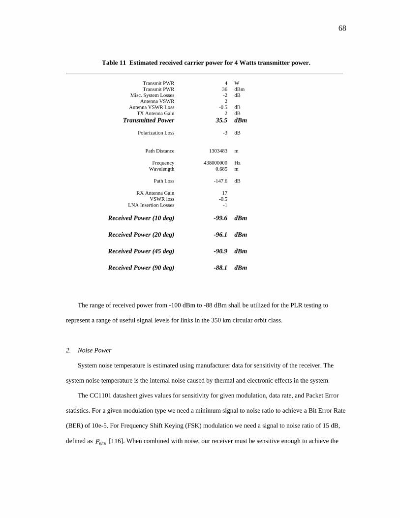
68
Table 11 Estimated received carrier power for 4 Watts transmitter power.
Transmit PWR 4 W Transmit PWR 36 dBm
Misc. System Losses -2 dB Antenna VSWR 2
Antenna VSWR Loss -0.5 dB TX Antenna Gain 2 dB
Transmitted Power 35.5 dBm
Polarization Loss -3 dB
Path Distance 1303483 m
Frequency 438000000 Hz Wavelength 0.685 m
Path Loss -147.6 dB
RX Antenna Gain 17
VSWR loss -0.5 LNA Insertion Losses -1
Received Power (10 deg) -99.6 dBm
Received Power (20 deg) -96.1 dBm
Received Power (45 deg) -90.9 dBm
Received Power (90 deg) -88.1 dBm
The range of received power from -100 dBm to -88 dBm shall be utilized for the PLR testing to
represent a range of useful signal levels for links in the 350 km circular orbit class.
2. Noise Power
System noise temperature is estimated using manufacturer data for sensitivity of the receiver. The
system noise temperature is the internal noise caused by thermal and electronic effects in the system.
The CC1101 datasheet gives values for sensitivity for given modulation, data rate, and Packet Error
statistics. For a given modulation type we need a minimum signal to noise ratio to achieve a Bit Error Rate
(BER) of 10e-5. For Frequency Shift Keying (FSK) modulation we need a signal to noise ratio of 15 dB,
defined as [116]. When combined with noise, our receiver must be sensitive enough to achieve the BERP
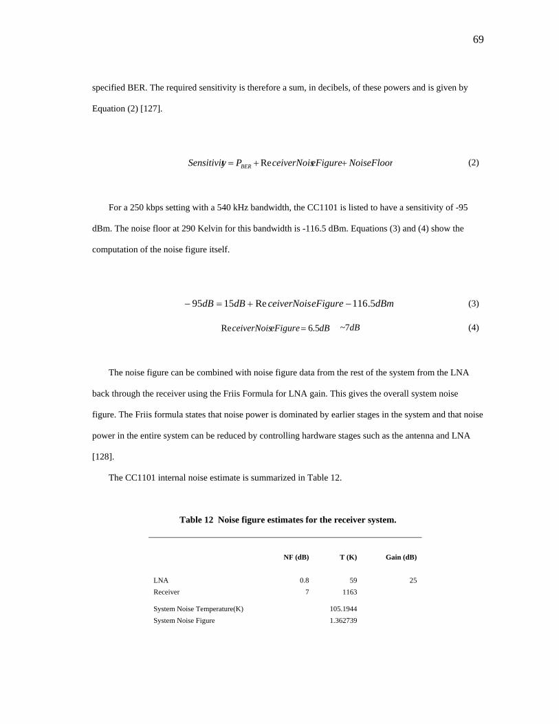
69
specified BER. The required sensitivity is therefore a sum, in decibels, of these powers and is given by
Equation (2) [127].
NoiseFlooreFigureceiverNoisPySensitivit BER ++= Re (2)
For a 250 kbps setting with a 540 kHz bandwidth, the CC1101 is listed to have a sensitivity of -95
dBm. The noise floor at 290 Kelvin for this bandwidth is -116.5 dBm. Equations (3) and (4) show the
computation of the noise figure itself.
dBmeFigureceiverNoisdBdB 5.116Re1595 + −=−
dBeFigureceiverNois 5.6Re
(3)
= ~7dB (4)
The noise figure can be combined with noise figure data from the rest of the system from the LNA
back through the receiver using the Friis Formula for LNA gain. This gives the overall system noise
figure. The Friis formula states that noise power is dominated by earlier stages in the system and that noise
power in the entire system can be reduced by controlling hardware stages such as the antenna and LNA
[128].
The CC1101 internal noise estimate is summarized in Table 12.
Table 12 Noise figure estimates for the receiver system.
NF (dB) T (K) Gain (dB) LNA 0.8 59 25 Receiver 7 1163 System Noise Temperature(K) 105.1944 System Noise Figure 1.362739
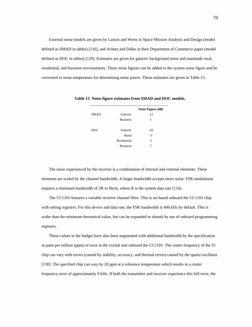
70
External noise models are given by Larson and Wertz in Space Mission Analysis and Design (model
defined as SMAD in tables) [116], and Achatz and Dalke in their Department of Commerce paper (model
defined as DOC in tables) [129]. Estimates are given for galactic background noise and manmade rural,
residential, and business environments. These noise figures can be added to the system noise figure and be
converted to noise temperature for determining noise power. These estimates are given in Table 13.
Table 13 Noise figure estimates from SMAD and DOC models.
Noise Figure (dB) SMAD Galactic -12 Business 1 DOC Galactic -10 Rural -3 Residential 3 Business 7
The noise experienced by the receiver is a combination of internal and external elements. These
elements are scaled by the channel bandwidth. A larger bandwidth accepts more noise. FSK modulation
requires a minimum bandwidth of 2R in Hertz, where R is the system data rate [116].
The CC1101 features a variable receiver channel filter. This is set based onboard the CC1101 chip
with setting registers. For this device and data rate, the FSK bandwidth is 406 kHz by default. This is
wider than the minimum theoretical value, but can be expanded or shrunk by use of onboard programming
registers.
These values in the budget have also been augmented with additional bandwidth by the specification
in parts per million (ppm) of error in the crystal unit onboard the CC1101. The center frequency of the TI
chip can vary with errors (caused by stability, accuracy, and thermal errors) caused by the quartz oscillator
[130]. The specified chip can vary by 20 ppm at a reference temperature which results in a center
frequency error of approximately 9 kHz. If both the transmitter and receiver experience this full error, the
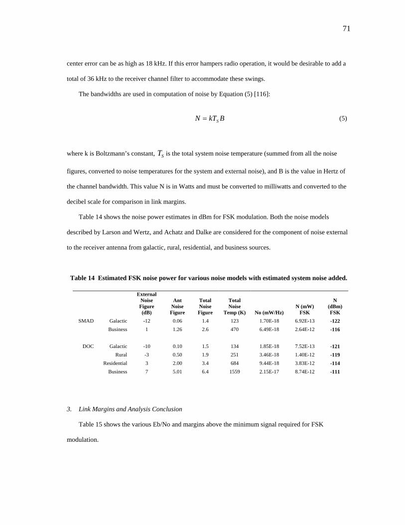
71
center error can be as high as 18 kHz. If this error hampers radio operation, it would be desirable to add a
total of 36 kHz to the receiver channel filter to accommodate these swings.
The bandwidths are used in computation of noise by Equation (5) [116]:
BkTN S= (5)
where k is Boltzmann’s constant, is the total system noise temperature (summed from all the noise
figures, converted to noise temperatures for the system and external noise), and B is the value in Hertz of
the channel bandwidth. This value N is in Watts and must be converted to milliwatts and converted to the
decibel scale for comparison in link margins.
ST
Table 14 shows the noise power estimates in dBm for FSK modulation. Both the noise models
described by Larson and Wertz, and Achatz and Dalke are considered for the component of noise external
to the receiver antenna from galactic, rural, residential, and business sources.
Table 14 Estimated FSK noise power for various noise models with estimated system noise added.
External Noise Figure (dB)
Ant Noise Figure
Total Noise
Figure
Total Noise
Temp (K) No (mW/Hz) N (mW)
FSK
N (dBm) FSK
SMAD Galactic -12 0.06 1.4 123 1.70E-18 6.92E-13 -122 Business 1 1.26 2.6 470 6.49E-18 2.64E-12 -116
DOC Galactic -10 0.10 1.5 134 1.85E-18 7.52E-13 -121 Rural -3 0.50 1.9 251 3.46E-18 1.40E-12 -119 Residential 3 2.00 3.4 684 9.44E-18 3.83E-12 -114 Business 7 5.01 6.4 1559 2.15E-17 8.74E-12 -111
3. Link Margins and Analysis Conclusion
Table 15 shows the various Eb/No and margins above the minimum signal required for FSK
modulation.
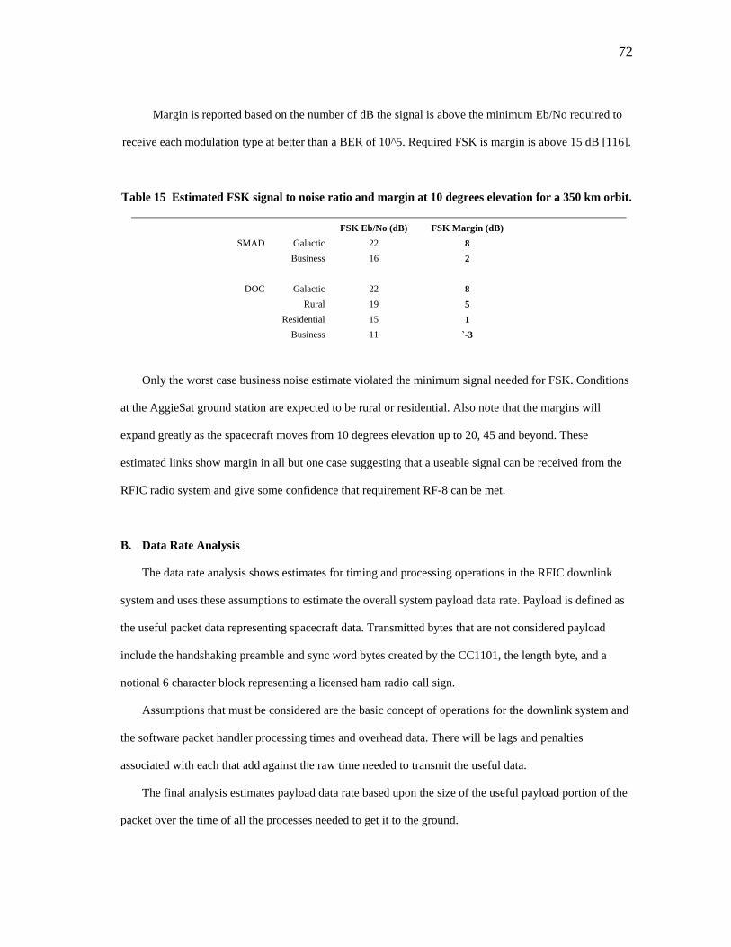
72
Margin is reported based on the number of dB the signal is above the minimum Eb/No required to
receive each modulation type at better than a BER of 10^5. Required FSK is margin is above 15 dB [116].
Table 15 Estimated FSK signal to noise ratio and margin at 10 degrees elevation for a 350 km orbit.
FSK Eb/No (dB) FSK Margin (dB) SMAD Galactic 22 8
Business 16 2
DOC Galactic 22 8 Rural 19 5 Residential 15 1 Business 11 `-3
Only the worst case business noise estimate violated the minimum signal needed for FSK. Conditions
at the AggieSat ground station are expected to be rural or residential. Also note that the margins will
expand greatly as the spacecraft moves from 10 degrees elevation up to 20, 45 and beyond. These
estimated links show margin in all but one case suggesting that a useable signal can be received from the
RFIC radio system and give some confidence that requirement RF-8 can be met.
B. Data Rate Analysis
The data rate analysis shows estimates for timing and processing operations in the RFIC downlink
system and uses these assumptions to estimate the overall system payload data rate. Payload is defined as
the useful packet data representing spacecraft data. Transmitted bytes that are not considered payload
include the handshaking preamble and sync word bytes created by the CC1101, the length byte, and a
notional 6 character block representing a licensed ham radio call sign.
Assumptions that must be considered are the basic concept of operations for the downlink system and
the software packet handler processing times and overhead data. There will be lags and penalties
associated with each that add against the raw time needed to transmit the useful data.
The final analysis estimates payload data rate based upon the size of the useful payload portion of the
packet over the time of all the processes needed to get it to the ground.
73
The ultimate rate is reported after finally considering various percentages of lost packets and re-sends
for those packets. Loss rates of 0, 25, and 50 % are reported to give a range of expected data rate
performance. The derivation for the PLR penalty on data rate is given in Appendix B.
1. RFIC System Concept of Operations
The preliminary design of the RFIC downlink system assumes that packets are to be sent closed loop
with the spacecraft requiring responses from the ground to indicate whether or not to re-send the current
packet or to send the next one.
This is the simplest concept and gives a user maximum control over the packet send process. This is
very inefficient from a time perspective because it requires the spacecraft to wait for a response and incur
light transit time of radio signals two ways. The system does require a simple checksum (assumed here to
be an extra byte) to give the ground system a means to detect if a packet is corrupted or not and make a
processing decision. It is assumed that the ground segment will make a decision about the current packet,
either by reception of the checksum or a timeout as to whether or not to request a re-send or shift to the
next packet.
The alternative is to stream the data with proper checksums that not only indicate if bit errors have
occurred in a given packet, but can be used mathematically to recover lost data. This requires more
sophistication in the actual packet format. The key challenge is using an algorithm to detect and correct
errors that minimizes additional byte overhead and can correct enough bad bytes per packet to keep pace
with the bit error statistics.
The basic closed loop system is shown in Figure 16. An independent uplink segment is assumed to
allow for usage of amplification equipment on the RFIC system segment. The packet responses and
requests flow through this independent uplink. AggieSat4, the next AggieSat Lab spacecraft, is already
carrying a low data rate system for this purpose as well as for redundancy.
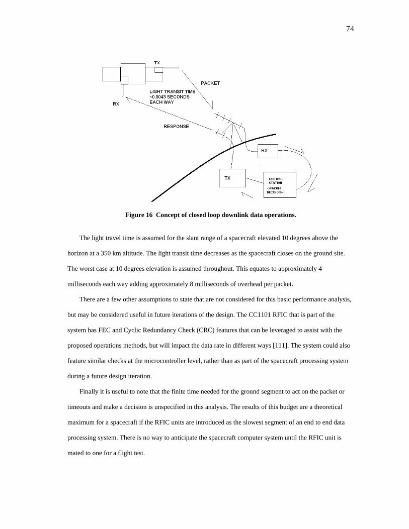
74
Figure 16 Concept of closed loop downlink data operations.
The light travel time is assumed for the slant range of a spacecraft elevated 10 degrees above the
horizon at a 350 km altitude. The light transit time decreases as the spacecraft closes on the ground site.
The worst case at 10 degrees elevation is assumed throughout. This equates to approximately 4
milliseconds each way adding approximately 8 milliseconds of overhead per packet.
There are a few other assumptions to state that are not considered for this basic performance analysis,
but may be considered useful in future iterations of the design. The CC1101 RFIC that is part of the
system has FEC and Cyclic Redundancy Check (CRC) features that can be leveraged to assist with the
proposed operations methods, but will impact the data rate in different ways [111]. The system could also
feature similar checks at the microcontroller level, rather than as part of the spacecraft processing system
during a future design iteration.
Finally it is useful to note that the finite time needed for the ground segment to act on the packet or
timeouts and make a decision is unspecified in this analysis. The results of this budget are a theoretical
maximum for a spacecraft if the RFIC units are introduced as the slowest segment of an end to end data
processing system. There is no way to anticipate the spacecraft computer system until the RFIC unit is
mated to one for a flight test.
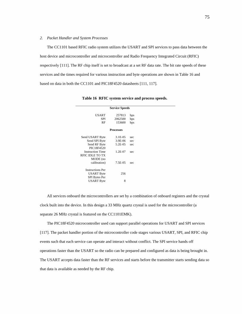
75
2. Packet Handler and System Processes
The CC1101 based RFIC radio system utilizes the USART and SPI services to pass data between the
host device and microcontroller and microcontroller and Radio Frequency Integrated Circuit (RFIC)
respectively [111]. The RF chip itself is set to broadcast at a set RF data rate. The bit rate speeds of these
services and the times required for various instruction and byte operations are shown in Table 16 and
based on data in both the CC1101 and PIC18F4520 datasheets [111, 117].
Table 16 RFIC system service and process speeds.
Service Speeds
USART 257813 bps SPI 2062500 bps RF 153600 bps
Processes
Send USART Byte 3.1E-05 sec Send SPI Byte 3.9E-06 sec Send RF Byte 5.2E-05 sec PIC18F4520
Instruction Time 1.2E-07 sec RFIC IDLE TO TX
MODE (no calibration) 7.5E-05 sec
Instructions Per
USART Byte 256 SPI Bytes Per USART Byte 8
All services onboard the microcontrollers are set by a combination of onboard registers and the crystal
clock built into the device. In this design a 33 MHz quartz crystal is used for the microcontroller (a
separate 26 MHz crystal is featured on the CC1101EMK).
The PIC18F4520 microcontroller used can support parallel operations for USART and SPI services
[117]. The packet handler portion of the microcontroller code stages various USART, SPI, and RFIC chip
events such that each service can operate and interact without conflict. The SPI service hands off
operations faster than the USART so the radio can be prepared and configured as data is being brought in.
The USART accepts data faster than the RF services and starts before the transmitter starts sending data so
that data is available as needed by the RF chip.
76
Approximately 70 microseconds is required before the transmitter begins sending meaningful data.
This is taken up by extra instruction and configuration time needed to get the CC1101 transmitting and
counts against the overall data rate.
Each packet is initiated in the microcontroller by sending the microcontroller a prefix byte that
instructs the controller if an outgoing data packet or commands follow. If outgoing data is coming this is
followed by a length byte that travels end to end with the packet to inform all devices in the system the
length of data expected. The packets are variable in length of data from 1 to 243 bytes.
During the writing of these two bytes several instructions and a SPI byte are handled by the
microcontroller. The actual commanding of the RFIC to start occurs in parallel with the third USART byte
sent, which represents the first data payload byte. The microcontroller handles a read instruction to grab
the length byte and sends three SPI bytes to pass the length byte to the radio before the start transmit
command is sent.
At this point all microcontroller instructions, USART operations, and SPI operations lead the RFIC
transmit operations. All remaining time is therefore paced by the time it takes for the RFIC to handle the
RF transmission.
When transmitting the payload bytes are accompanied by the aforementioned length byte and a 2 byte
preamble and 2 byte sync word. These additional bytes are included in the RF transmission overhead.
3. System Data Rate Estimate
Table 17 shows estimated data rates for a system with the aforementioned assumptions. Three
scenarios are shown. Each is penalized by a different PLR. The time required to re-send each of these
dropped packets once is penalized against the overall transmit time of the useful payload data to determine
the theoretical maximum payload data rate.
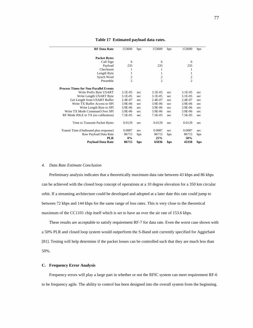
77
Table 17 Estimated payload data rates.
RF Data Rate 153600 bps 153600 bps 153600 bps
Packet Bytes Call Sign 6 6 6
Payload 235 235 235 Checksum 1 1 1
Length Byte 1 1 1 Synch Word 2 2 2
Preamble 2 2 2
Process Times for Non Parallel Events Write Prefix Byte USART 3.1E-05 sec 3.1E-05 sec 3.1E-05 sec
Write Length USART Byte 3.1E-05 sec 3.1E-05 sec 3.1E-05 sec Get Length from USART Buffer 2.4E-07 sec 2.4E-07 sec 2.4E-07 sec
Write TX Buffer Access to SPI 3.9E-06 sec 3.9E-06 sec 3.9E-06 sec Write Length Byte to SPI 3.9E-06 sec 3.9E-06 sec 3.9E-06 sec
Write TX Mode Command Over SPI 3.9E-06 sec 3.9E-06 sec 3.9E-06 sec RF Mode IDLE to TX (no calibration) 7.5E-05 sec 7.5E-05 sec 7.5E-05 sec
Time to Transmit Packet Bytes 0.0129 sec 0.0129 sec 0.0129 sec
Transit Time (Outbound plus response) 0.0087 sec 0.0087 sec 0.0087 sec
Raw Payload Data Rate 86715 bps 86715 bps 86715 bps PLR 0% 25% 50%
Payload Data Rate 86715 bps 65036 bps 43358 bps
4. Data Rate Estimate Conclusion
Preliminary analysis indicates that a theoretically maximum data rate between 43 kbps and 86 kbps
can be achieved with the closed loop concept of operations at a 10 degree elevation for a 350 km circular
orbit. If a streaming architecture could be developed and adopted at a later date this rate could jump to
between 72 kbps and 144 kbps for the same range of loss rates. This is very close to the theoretical
maximum of the CC1101 chip itself which is set to have an over the air rate of 153.6 kbps.
These results are acceptable to satisfy requirement RF-7 for data rate. Even the worst case shown with
a 50% PLR and closed loop system would outperform the S-Band unit currently specified for AggieSat4
[81]. Testing will help determine if the packet losses can be controlled such that they are much less than
50%.
C. Frequency Error Analysis
Frequency errors will play a large part in whether or not the RFIC system can meet requirement RF-6
to be frequency agile. The ability to control has been designed into the overall system from the beginning.
78
This capability must be effective in combating errors in center frequency or the unit itself must be tolerant
of such errors.
There will be errors in frequency caused by unknown variations in the hardware (specifically in the
CC1101 unit and its crystal oscillator), temperature changes, and most expectedly by Doppler shift during
satellite ground passes. Each will be examined to help define offset PLR testing.
1. Internal vs. Externally Stressed Errors
Both thermal effects and Doppler shift shall be considered externally stressed errors because they are
caused by the environmental effects of temperature conditions and spacecraft orbital motion. The offset
PLR tests will be designed to simulate these two effects by artificially tuning the transmitter out of band
by the expected magnitudes.
Any unknown internal errors inherent in the hardware will remain unknown except by observation of
the RFIC unit’s center band at some reference. These errors will also be present in the as built system
regardless of external conditions real or simulated. Each pairing of RFIC transmitter and receiver units
will come with a set of these conditions once final assembly is complete. Variation in the hardware itself
can result from variability in materials to the manufacturing process itself.
The crystal oscillator unit used to time the CC1101 circuitry is expected to be especially susceptible to
such effects. This is because crystal oscillator accuracy and stability is commonly referred to in literature
and Texas Instruments has specifically allocated an entire design note on the CC1101 stating that errors in
the crystal oscillator unit translate directly into errors of the center band [131, 132, 130].
Testing data taken for this thesis on behalf of the test objectives outlined in the verification plan
includes data on the center frequencies of the FSK modulated peaks. The center of the two peaks can be
calculated from this test data and a rough measurement of true center frequency versus programmed can
be obtained.
While not tracked, AggieSat Lab room temperatures usually vary between 21 and 26 C so most
testing has occurred near 25C, which is the reference temperature for the NDK AT-41CD2 AT crystal
associated with the device [133]. Data for 156 runs in this environment featured an average error between
79
true center and programmed center (436.2498 MHz) of approximately 10.5 kHz. The CC1101 and
associated RFIC systems have been operating normally with this inherent error.
2. Crystal Oscillator Accuracy, Stability, and Thermal Effects
The frequency tolerance of a crystal oscillator is defined as the initial deviation from the nominal
frequency expressed in parts per million (ppm) at a reference temperature (in this case 25 C). The
frequency stability tolerance over temperature is the deviation of the frequency from the initial measured
deviation at 25 C over the crystal’s operating range [131].
Additive tolerances and errors in materials and construction of the device will result in an overall
frequency tolerance of the device at the reference temperature.
The CC1101EMK uses a 26 MHz variant of the NDK AT-41CD2 AT quartz crystal device [133]. The
frequency tolerance is specified as +/- 20 ppm. The stability tolerance over temperature (quoted as
frequency versus temperature characteristic) is +/-30ppm. The specified operating temperature range of
the device is -10 to 70 C.
Texas Instruments states in the crystal accuracy design note that when using a given crystal that a
given ppm error in the reference crystal will cause the same ppm error in the CC1101 device output [130].
For an operational frequency of 436.25 MHz (as in our preliminary design) a 20 ppm reference error
would result in an estimated +/-9 kHz error. This is demonstrated by Equation 6.
kHzMHzMHz 9/087.0/25.436*000020.0/ −+≅−+=−+ (6)
This result is very similar to the average 10.5 kHz observed operating the RFIC units in the laboratory
and suggests, just like available documentation, that crystal effects translate directly into frequency control
errors.
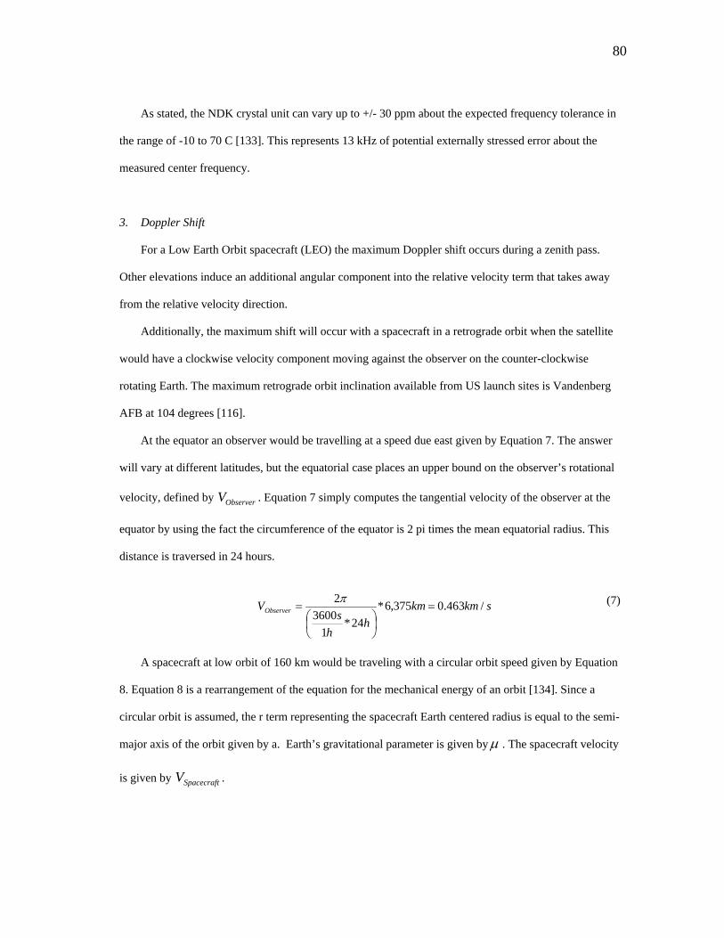
80
As stated, the NDK crystal unit can vary up to +/- 30 ppm about the expected frequency tolerance in
the range of -10 to 70 C [133]. This represents 13 kHz of potential externally stressed error about the
measured center frequency.
3. Doppler Shift
For a Low Earth Orbit spacecraft (LEO) the maximum Doppler shift occurs during a zenith pass.
Other elevations induce an additional angular component into the relative velocity term that takes away
from the relative velocity direction.
Additionally, the maximum shift will occur with a spacecraft in a retrograde orbit when the satellite
would have a clockwise velocity component moving against the observer on the counter-clockwise
rotating Earth. The maximum retrograde orbit inclination available from US launch sites is Vandenberg
AFB at 104 degrees [116].
At the equator an observer would be travelling at a speed due east given by Equation 7. The answer
will vary at different latitudes, but the equatorial case places an upper bound on the observer’s rotational
velocity, defined by . Equation 7 simply computes the tangential velocity of the observer at the
equator by using the fact the circumference of the equator is 2 pi times the mean equatorial radius. This
distance is traversed in 24 hours.
ObserverV
skmkmh
hs
VObserver /463.0375,6*24*
13600
2=
⎟⎠⎞
⎜⎝⎛
=π (7)
A spacecraft at low orbit of 160 km would be traveling with a circular orbit speed given by Equation
8. Equation 8 is a rearrangement of the equation for the mechanical energy of an orbit [134]. Since a
circular orbit is assumed, the r term representing the spacecraft Earth centered radius is equal to the semi-
major axis of the orbit given by a. Earth’s gravitational parameter is given byμ . The spacecraft velocity
is given by . SpacecraftV
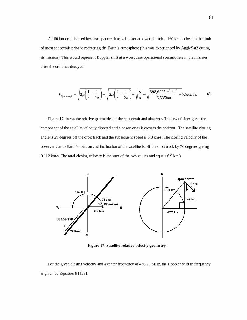
81
A 160 km orbit is used because spacecraft travel faster at lower altitudes. 160 km is close to the limit
of most spacecraft prior to reentering the Earth’s atmosphere (this was experienced by AggieSat2 during
its mission). This would represent Doppler shift at a worst case operational scenario late in the mission
after the orbit has decayed.
skmkm
skmaaaar
VSpacecraft /8.7535,6
/600,3982112
2112
23
===⎟⎠⎞
⎜⎝⎛ −=⎟
⎠⎞
⎜⎝⎛ −=
μμμ (8)
Figure 17 shows the relative geometries of the spacecraft and observer. The law of sines gives the
component of the satellite velocity directed at the observer as it crosses the horizon. The satellite closing
angle is 29 degrees off the orbit track and the subsequent speed is 6.8 km/s. The closing velocity of the
observer due to Earth’s rotation and inclination of the satellite is off the orbit track by 76 degrees giving
0.112 km/s. The total closing velocity is the sum of the two values and equals 6.9 km/s.
Figure 17 Satellite relative velocity geometry.
For the given closing velocity and a center frequency of 436.25 MHz, the Doppler shift in frequency
is given by Equation 9 [128].
82
MHzMHzsm
smfc
Vf o
relative 010.025.436/000,000,300
/900,6−=−=−=Δ (9)
The change in frequency is given by fΔ , is the carrier frequency, is the relative velocity
between the spacecraft and the observer, and c is the speed of light. Doppler shift would be approximately
-10 kHz closing at the horizon. The Doppler shift would drop to zero at zenith, and then back to +10 kHz
receding from the observer.
of relativeV
4. Frequency Error Conclusion
Major external perturbations in center frequency are expected to be thermally induced up to 13 kHz
over the -10 to 70 C range, and Doppler shift induced up to an additional 10 kHz. A total of 23 kHz
variance on either side of the center frequency is expected.
The estimated magnitudes of these external perturbations can be used to manually offset a test
transmitter and determine if the RFIC units are tolerant to frequency errors in this range. The internal
errors will not be replicated in testing because they would duplicate the errors already present in an as built
unit. A statistical analysis of these internal properties would require sample data from multiple units
constructed by the same processes. The CC1101 and RFIC system have been operated functionally with
the inherent 10.5 kHz error in the commanded frequency that correlates in magnitude to the expected
frequency tolerance of the onboard quartz crystal.
Based upon setting capabilities of the CC1101 chip, the expected tuning resolution is approximately
0.4 kHz. It is also important to see what the actual tuning resolution of the CC1101 chip and support
hardware is in testing.
The data in this analysis will help support testing and verification of requirement RF-6.

83
VIII. OSCILLOSCOPE TESTING RESULTS
A. Scope of Results
Oscilloscope results can be used to directly verify the timing operation of the RFIC units and
determine actual numbers valuable to data rate computation. The other half of this picture is the Packet
Loss Rate test which will be evaluated later to see how successful the actual data transmission is during
each duty cycle. It is expected that some to be measured percentage of packets working on typical duty
cycles will be lost.
Each RFIC unit submitted to this and all other testing outlined in the thesis successfully passed the
basic functional test outlined earlier. The pass fail results of the basic functional tests are recorded along
with certification logs and other internal documentation at AggieSat Lab on the RFIC units.
The structure of a packet duty cycle is evaluated two ways. First is at the USART interface level.
Each of two oscilloscope channels will be monitoring the outgoing USART data from the simulated
spacecraft data terminal and the incoming USART data entering the simulated ground terminal. The time
bounded by these services captures the total time required between data leaving a command and data
handling system, through RF transmission, and into a ground terminal arrangement.
A second method will monitor an auxiliary pin set up to fire only when the interrupt services of the
RFIC control units are in play. It is expected that this should take slightly longer than the duty cycle
between the USART services because the interrupt handler has a few finite instructions that occur between
an interrupt event and the start of USART and RF communications.
A second line of evaluation involves the structure of repeated packet sequences. The packet send
events will be cycled and delays will be produced in between each set of packets. Timing of repeated
packet sequences will be evaluated for both long and short range light travel times. These light travel delay
times will represent the closed loop concept of operations that has been described. These times force the
packet handlers and RFIC units to rest as if the system is waiting for responses from the ground site to
travel.
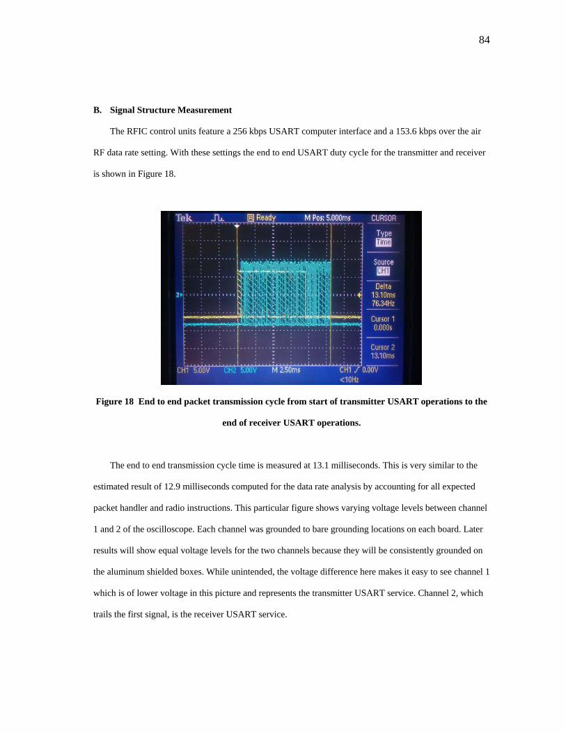
84
B. Signal Structure Measurement
The RFIC control units feature a 256 kbps USART computer interface and a 153.6 kbps over the air
RF data rate setting. With these settings the end to end USART duty cycle for the transmitter and receiver
is shown in Figure 18.
Figure 18 End to end packet transmission cycle from start of transmitter USART operations to the
end of receiver USART operations.
The end to end transmission cycle time is measured at 13.1 milliseconds. This is very similar to the
estimated result of 12.9 milliseconds computed for the data rate analysis by accounting for all expected
packet handler and radio instructions. This particular figure shows varying voltage levels between channel
1 and 2 of the oscilloscope. Each channel was grounded to bare grounding locations on each board. Later
results will show equal voltage levels for the two channels because they will be consistently grounded on
the aluminum shielded boxes. While unintended, the voltage difference here makes it easy to see channel 1
which is of lower voltage in this picture and represents the transmitter USART service. Channel 2, which
trails the first signal, is the receiver USART service.
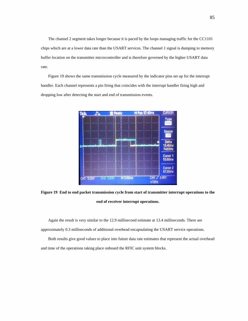
85
The channel 2 segment takes longer because it is paced by the loops managing traffic for the CC1101
chips which are at a lower data rate than the USART services. The channel 1 signal is dumping to memory
buffer location on the transmitter microcontroller and is therefore governed by the higher USART data
rate.
Figure 19 shows the same transmission cycle measured by the indicator pins set up for the interrupt
handler. Each channel represents a pin firing that coincides with the interrupt handler firing high and
dropping low after detecting the start and end of transmission events.
Figure 19 End to end packet transmission cycle from start of transmitter interrupt operations to the
end of receiver interrupt operations.
Again the result is very similar to the 12.9 millisecond estimate at 13.4 milliseconds. There are
approximately 0.3 milliseconds of additional overhead encapsulating the USART service operations.
Both results give good values to place into future data rate estimates that represent the actual overhead
and time of the operations taking place onboard the RFIC unit system blocks.
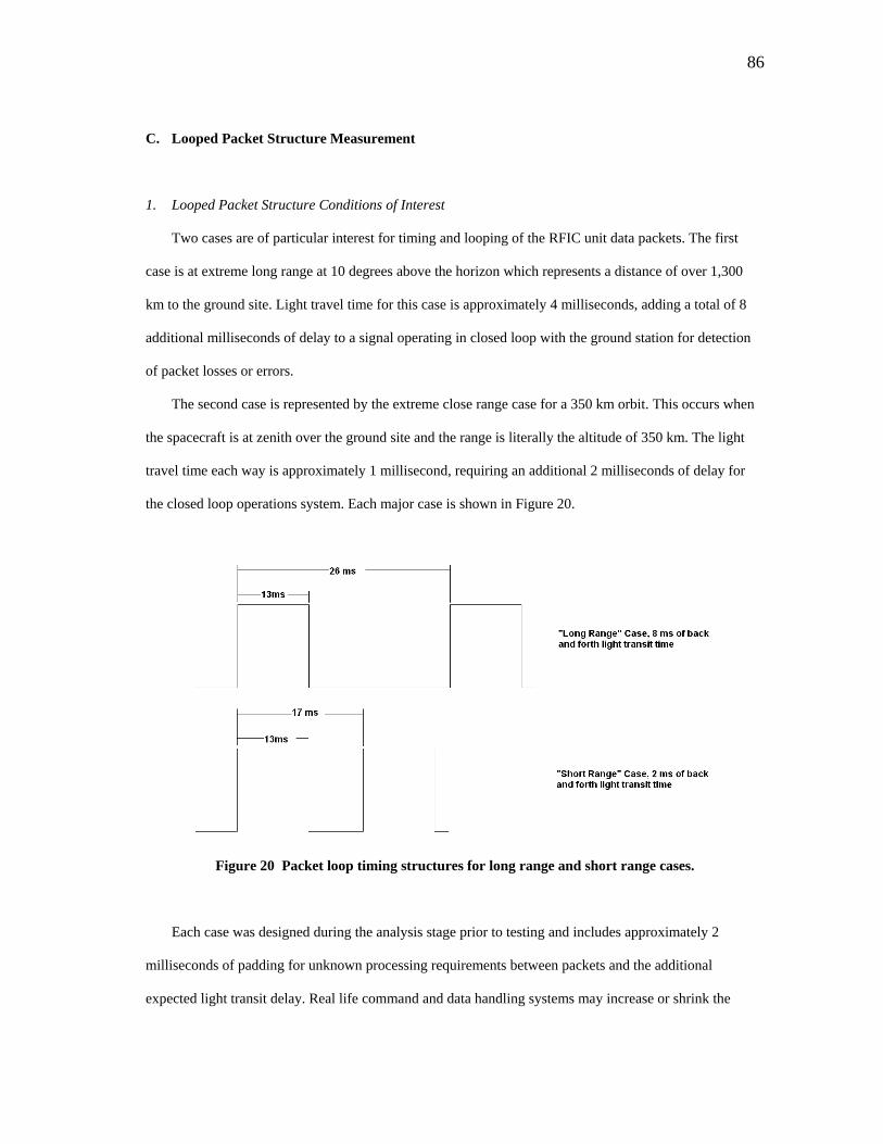
86
C. Looped Packet Structure Measurement
1. Looped Packet Structure Conditions of Interest
Two cases are of particular interest for timing and looping of the RFIC unit data packets. The first
case is at extreme long range at 10 degrees above the horizon which represents a distance of over 1,300
km to the ground site. Light travel time for this case is approximately 4 milliseconds, adding a total of 8
additional milliseconds of delay to a signal operating in closed loop with the ground station for detection
of packet losses or errors.
The second case is represented by the extreme close range case for a 350 km orbit. This occurs when
the spacecraft is at zenith over the ground site and the range is literally the altitude of 350 km. The light
travel time each way is approximately 1 millisecond, requiring an additional 2 milliseconds of delay for
the closed loop operations system. Each major case is shown in Figure 20.
Figure 20 Packet loop timing structures for long range and short range cases.
Each case was designed during the analysis stage prior to testing and includes approximately 2
milliseconds of padding for unknown processing requirements between packets and the additional
expected light transit delay. Real life command and data handling systems may increase or shrink the
87
requirements for the additional padding. The cases shown are the simulation targets for testing and
intended to demonstrate the basic functionality of the system.
Another area of difference between these simulated cases and real life cases is that the delay occurs
after the entire packet transmission event. In real life the light transit delays will occur between the
transmit and the receive portion of the transmission events. This cannot be duplicated without a
complicated store and forward system located in the test loop and this has not been implemented. The
represented delays are still included because, while out of order, they force the RFIC units and associated
components and memories to rest the appropriate amount of time between packet events. This preserves
the proper duty cycle from an electrical standpoint.
Furthermore, the packet handling events are also designed to occur in linear fashion without any
feedback from the receiver to transmitter before the end of the packet transmission cycle. Any feedback
that occurs after transmission is external to the RFIC units in the context of the first generation closed loop
system. The difference in placement of the delay between the testing and flight is not expected to be
significant because of this fact.
2. Timing Problems and Solutions with Computer Testing Terminals
An interesting development that occurred during testing that had to be resolved was a timing problem
using the original packet generator and counting system developed in LabVIEW.
Originally LabVIEW was utilized to generate fully randomized byte data, attach a properly formatted
header with command structure and call sign, send this packet over the USART, receive over the USART,
and compare the data for errors and drops. Iterations of this system could not achieve a packet duty cycle
of less than 28 milliseconds. This is similar to the 26 millisecond long range case defined previously, but
prevented anything resembling the short range duty cycle case from being tested.
Initially it was discovered that the random number generator system itself took too much time (on the
order of 15 milliseconds) to execute for each packet loop. Even if fully randomized data could not be
achieved in a timely manner, this had to be replaced in a way that still forced all the associated memories
and buffers throughout the system to cycle from packet to packet. This would ensure that data already

88
recorded was not being resubmitted to the packet drop and error counter system even if the RF segment
was losing data.
A two packet system was created where two previously written text files would be alternated through
the system forcing the buffer system throughout to be overwritten from packet cycle to packet cycle. Pre-
written text files are more representative of real operations anyway because a real spacecraft is not
generating data as it is being transmitted. A real spacecraft simply pulls existing data from stored memory
locations.
This system was implemented, but it was found that another parallel process was still occurring in the
LabVIEW control system that prevented the duty cycle from being shortened properly.
The RFIC units were then replaced by a simple crossover cable system that forced the data to travel
directly from transmit to receive terminals on the test computer. This level of testing would help determine
if the delays were occurring on the RFIC unit side or the test terminal side.
Again the delay was the same. Up to this point both transmit and receive test functions were being
handled by one LabVIEW program on one computer. This required the program and the computer to
juggle two serial port objects simultaneously. Subsequent crossover runs were conducted with the transmit
and receive portions split first between two different LabVIEW programs and then split and run on two
different workstations.
In both new cases the delay remained. Use of the digital oscilloscope on the transmitter terminal
confirmed that the transmit function was occurring in the expected amount of time. It was at this point
determined that the delay existed on the receive terminal side. Variations of artificial delays and ordering
changes on the receiver side could not eliminate the delay effect.
Two weeks of significant development effort were expended on troubleshooting LabVIEW. After this
time a new terminal system was tested to handle the receive portion.
Docklight V1.9 which is a purpose built serial interface terminal program was used to handle the
receive portions. The modified testing arrangement used the LabVIEW transmitter system to send the
alternating packets and Docklight was used to receive and count packets. Docklight scripting can be set to
detect unique byte patterns in a serial data stream and send a character string “flag” response when these
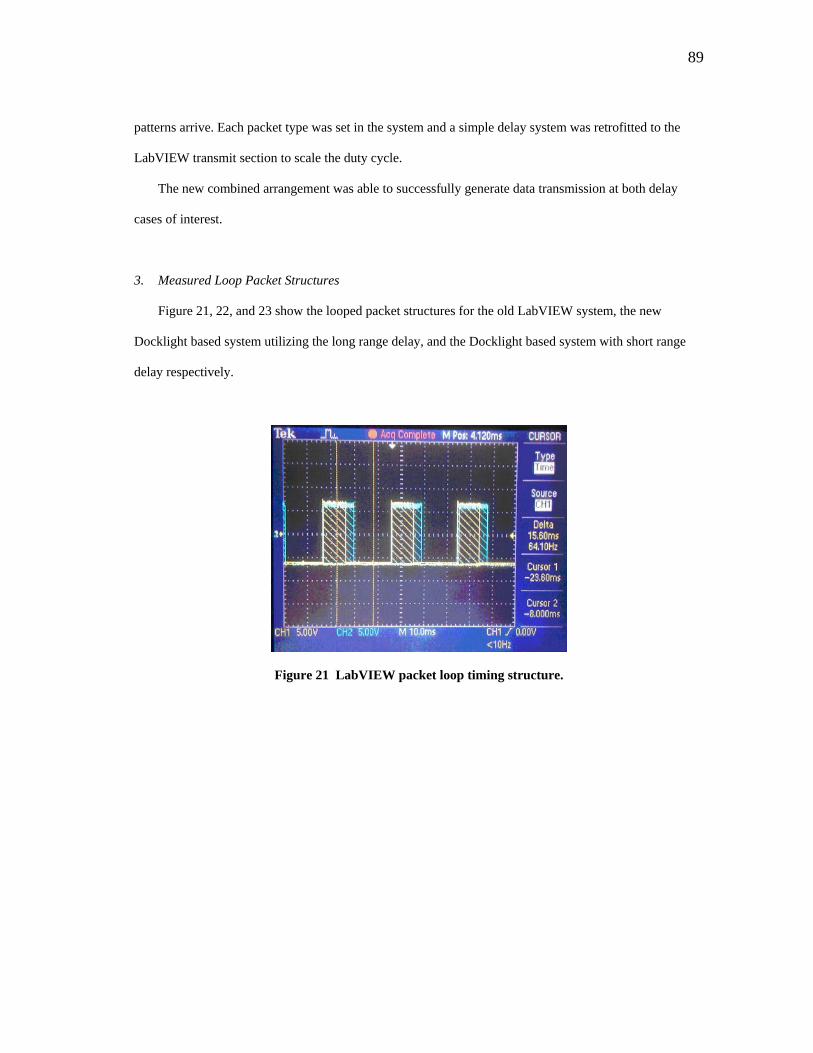
89
patterns arrive. Each packet type was set in the system and a simple delay system was retrofitted to the
LabVIEW transmit section to scale the duty cycle.
The new combined arrangement was able to successfully generate data transmission at both delay
cases of interest.
3. Measured Loop Packet Structures
Figure 21, 22, and 23 show the looped packet structures for the old LabVIEW system, the new
Docklight based system utilizing the long range delay, and the Docklight based system with short range
delay respectively.
Figure 21 LabVIEW packet loop timing structure.
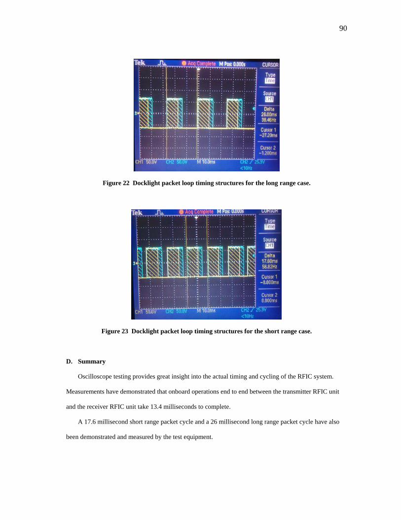
90
Figure 22 Docklight packet loop timing structures for the long range case.
Figure 23 Docklight packet loop timing structures for the short range case.
D. Summary
Oscilloscope testing provides great insight into the actual timing and cycling of the RFIC system.
Measurements have demonstrated that onboard operations end to end between the transmitter RFIC unit
and the receiver RFIC unit take 13.4 milliseconds to complete.
A 17.6 millisecond short range packet cycle and a 26 millisecond long range packet cycle have also
been demonstrated and measured by the test equipment.

91
Each packet cycle consists of 236 payload bytes, 6 call sign bytes, 1 length byte, 2 preamble bytes,
and 2 synch word bytes for a total of 247 over the air bytes (1976 bits). With long and short range transit
delays this equates to a raw data rate of 112 kbps and 76 kbps respectively. The useful data payload is 236
bytes, or 1888 bytes. The useful data rates with transit delays are 107 kbps to 72 kbps respectively.
Subsequent PLR test results will indicate what percentages of packets are successfully being
transmitted and will give us the final useful data rate of the system.
92
IX. PACKET LOSS RATE TESTING RESULTS
A. Scope of Results
Packet Loss Rate tests are designed to generate statistical information on packet throughput. The
original test setup as described in the Verification Plan Section is designed to provide an isolated RF
connection between the RFIC transmitter and receiver, attenuation to simulate spaceflight like signal
levels, and add white Gaussian noise to the overall arrangement.
The packet handling and statistics system has evolved during test experiences. An initial LabVIEW
based system was replaced by a combination LabVIEW and Docklight terminal systems that features
proper delays and generates radio payload by alternating between two possible data packets, affecting a
transmission event between the transmitter and receiver, and then compares the arriving data to the
intended message. If the data matches the signal is considered received and if it does not, or a timeout
passes, the packet is considered lost.
At the proof of concept level no distinction is made between packets with error and those dropped.
The initial LabVIEW setup was capable of this distinction, but it was not used when the old setup was in
operation. The reported statistics are a raw loss rate that indicates the lower bound of the systems data
throughput capability. It is possible that at some future date the packets with error can be leveraged by
correction schemes and the basic data rate result improved.
The intent within the scope of the thesis is to simply prove whether or not the basic rates and
performance meet the stated requirements and if the RFIC based system is worth further time expenditure
and development effort for small spacecraft applications.
The system loss statistics will be tested first against signal level variations, and then by frequency
offsets at some constant signal level. This will provide statistical information about the throughput
capability at flight like signal power levels and in the presence of perturbations on the center transmit
frequency.

93
Signal levels will be varied between -88 dBm and -100 dBm representing the range of flight signal
levels predicted by the previous link budget verification analysis. Offset tests will occur over a range of
positive to negative 25 kHz about a commanded center frequency of 436.2498 MHz.
Each test run using the PLR system loops 1,000 packets in succession on a duty cycle driven by the
desired transit delays for a scenario. Attenuation blocks in the test setup that absorb radio power are set for
each run according to the desired signal level. Signal levels are tested at roughly 2 dBm intervals and
1,000 packet cycles are run five times at each power level setting. Some variance of output levels for each
setting produces a spread about each power level and the actual measured levels are reported.
For each run the percentage of the 1,000 packets per run lost is plotted against either signal power
level or offset frequency to see how performance varies.
B. Noise Power Issues
The original test design featured simulated external noise. The total noise power entering the radio
receiver is a combination of external and internal elements. In a test scenario the internal noise is naturally
produced by the receiver electronics and is present no matter the conditions. The external noise must be
simulated in a test environment. A Gaussian white noise generator was acquired for this purpose.
Unfortunately the noise powers predicted by the link budget are significantly smaller than the signal
power. According to link budget approximations the combined noise effects of both the receiver and the
external elements is no greater than 14 dBm weaker than signal power. This means that even in our worst
case business noise model the total noise effect has nearly 1/32nd the power magnitude of the received
signal levels. The external component is even smaller than this because the predicted power is a
combination of internal and external noise.
These signal levels are outside of the resolution of the signal measurement capability of the on hand
spectrum analyzers available to AggieSat Lab. Signal levels between -100 and -105 dBm were already at
the noise floor of the HP8920A analyzer used for the major tests. It is thought that the noise generator and
attenuators used could easily produce the required simulated external noise power, but there was no way to
verify this for the tests themselves.
94
Tests that only feature internal noise power and varied signal levels will still build confidence in the
performance capability of the RFIC system because the internal noise is the largest noise component in
rural settings where our ground station is expected to operate. Furthermore, all predicted noise powers,
even those business environments, are extremely low compared to the received powers expected from the
space borne transmitter and specified amplifier. Reception of the space signal at the appropriate power
level will be an important first test of the system.
AggieSat Lab has already started discussing the problem with partners at NASA Johnson Space
Center to see if better, more sensitive test equipment can be used to complete test scenarios with an
external noise component. Our partners that are involved with GPS objectives for the next AggieSat flight
have already stated they believe they have equipment that can do the job and AggieSat Lab intends to
pursue this avenue through the fall.
Unfortunately this complication pushes the most complete version of signal power testing outside of
the time available scope of this thesis manuscript. This particular issue, which is based upon test
equipment limitations, highlights the difficulty of doing this kind of work outside of the government and
contractor realm. Unless the equipment is donated or inherited, it is hard to come by.
External noise power testing will be a part of the immediate future work for this concept. Link
analysis suggests that based upon signal power level magnitudes that the external noise should be a
relatively small component of a flight scenario. This research has highlighted the need to put this analysis
question to rest and AggieSat Lab will use its current partnerships to provide an answer in the near future.
A definitive answer settled with the help of our partners can be used to help other users and operators
develop similar RFIC systems.
C. Signal Level Test Results
The first batch of signal level results was completed using the original LabVIEW system with the
aforementioned timing problems unresolved. These results are shown in Figure 24.
These initial results are very promising. The data represents 30 1,000 packet runs over the range.
Packet Loss Rates are less than 10% from -96 dBm to -88 dBm. The grouping of 3 data sets in the upper
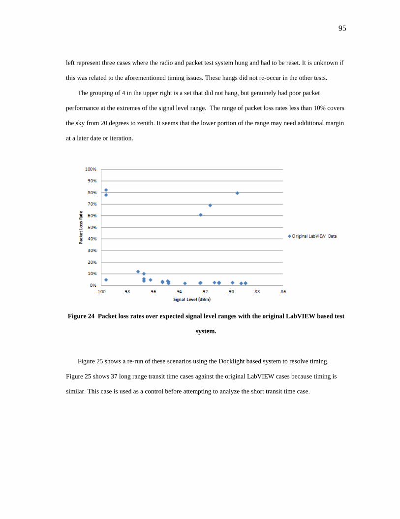
95
left represent three cases where the radio and packet test system hung and had to be reset. It is unknown if
this was related to the aforementioned timing issues. These hangs did not re-occur in the other tests.
The grouping of 4 in the upper right is a set that did not hang, but genuinely had poor packet
performance at the extremes of the signal level range. The range of packet loss rates less than 10% covers
the sky from 20 degrees to zenith. It seems that the lower portion of the range may need additional margin
at a later date or iteration.
Figure 24 Packet loss rates over expected signal level ranges with the original LabVIEW based test
system.
Figure 25 shows a re-run of these scenarios using the Docklight based system to resolve timing.
Figure 25 shows 37 long range transit time cases against the original LabVIEW cases because timing is
similar. This case is used as a control before attempting to analyze the short transit time case.
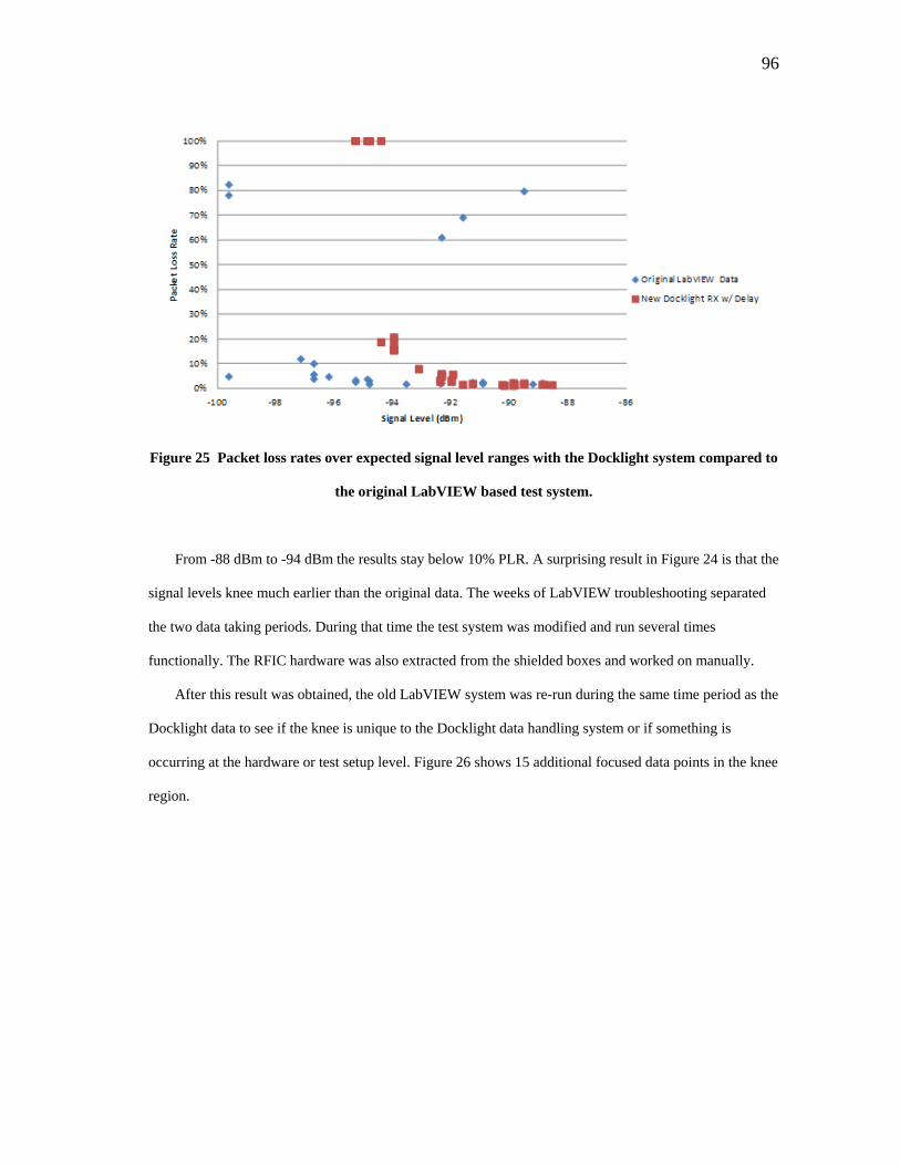
96
Figure 25 Packet loss rates over expected signal level ranges with the Docklight system compared to
the original LabVIEW based test system.
From -88 dBm to -94 dBm the results stay below 10% PLR. A surprising result in Figure 24 is that the
signal levels knee much earlier than the original data. The weeks of LabVIEW troubleshooting separated
the two data taking periods. During that time the test system was modified and run several times
functionally. The RFIC hardware was also extracted from the shielded boxes and worked on manually.
After this result was obtained, the old LabVIEW system was re-run during the same time period as the
Docklight data to see if the knee is unique to the Docklight data handling system or if something is
occurring at the hardware or test setup level. Figure 26 shows 15 additional focused data points in the knee
region.
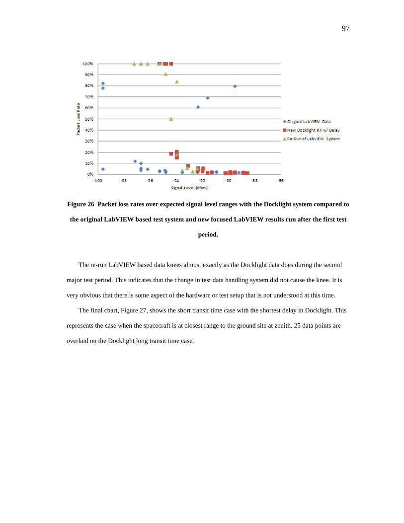
97
Figure 26 Packet loss rates over expected signal level ranges with the Docklight system compared to
the original LabVIEW based test system and new focused LabVIEW results run after the first test
period.
The re-run LabVIEW based data knees almost exactly as the Docklight data does during the second
major test period. This indicates that the change in test data handling system did not cause the knee. It is
very obvious that there is some aspect of the hardware or test setup that is not understood at this time.
The final chart, Figure 27, shows the short transit time case with the shortest delay in Docklight. This
represents the case when the spacecraft is at closest range to the ground site at zenith. 25 data points are
overlaid on the Docklight long transit time case.
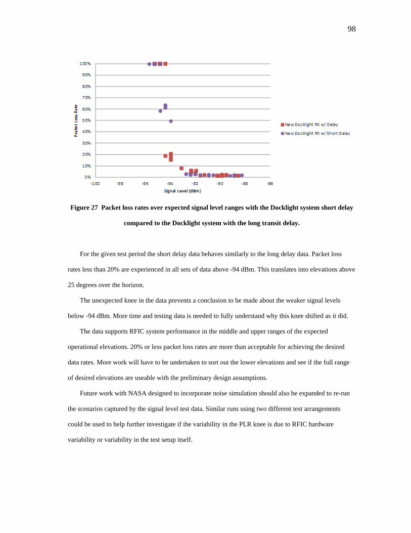
98
Figure 27 Packet loss rates over expected signal level ranges with the Docklight system short delay
compared to the Docklight system with the long transit delay.
For the given test period the short delay data behaves similarly to the long delay data. Packet loss
rates less than 20% are experienced in all sets of data above -94 dBm. This translates into elevations above
25 degrees over the horizon.
The unexpected knee in the data prevents a conclusion to be made about the weaker signal levels
below -94 dBm. More time and testing data is needed to fully understand why this knee shifted as it did.
The data supports RFIC system performance in the middle and upper ranges of the expected
operational elevations. 20% or less packet loss rates are more than acceptable for achieving the desired
data rates. More work will have to be undertaken to sort out the lower elevations and see if the full range
of desired elevations are useable with the preliminary design assumptions.
Future work with NASA designed to incorporate noise simulation should also be expanded to re-run
the scenarios captured by the signal level test data. Similar runs using two different test arrangements
could be used to help further investigate if the variability in the PLR knee is due to RFIC hardware
variability or variability in the test setup itself.
99
The end result of the signal level tests indicates that a workable system has been developed. It remains
to be seen if requirement RF-8, which stipulates that links are closed down to 10 degrees elevation, can be
met in its entirety. Several options still exist.
One possibility is that further test data taken in the future in conjunction with NASA could shore up
understanding of the variability in the test data and it prove that is it not an issue. Another possibility is
that the variability remains an issue after more is learned, but future iterations of the design tap into a wide
array of options in amplification, design arrangement, and ground station configuration that could add
margins to expand operational elevations down to 10 degrees.
One final thought to consider is that if the future flight version of this system is shown to work
operationally between zenith and 25 degrees, it is still a very useful radio system and can provide
improved data rate capacity for a lot of operational ground pass opportunities.
Iterations on this work are required to shore up performance and complete verification, positively or
negatively, for requirement RF-8. In the meantime, the results obtained to date show that the RFIC system
can provide capable data rates, with a high level of success, at signal power levels that are representative
of a large portion of estimated flight conditions.
D. Data Rate Calculation
Oscilloscope and PLR test results provide the information required to determine realistic data rate
expectations for the RFIC design. Two sets of performance will be quoted. The first is the streaming data
rate. This is the over the air system data rate if all packets were to stream one after the other based on the
time it takes for the RFIC system block to complete all functional instructions and tasks to send packets.
The second data rate performance will be a range over the light transit times from 10 degrees
elevation to zenith representative of a first generation operations concept that requires the ground station
to feed back packet confirmations.
Each performance determination is penalized by the 20% loss rate for signal powers of -94 dBm and
higher. This penalty is derived directly from the signal power results. Computation of the multiplying

100
factor for the PLR is explained by series in Appendix B. All data rates are the useful data rates of the
actual payload data of 236 bytes per packet.
The streaming data rate is given by Equation 10. This is the maximum supportable data rate based
upon the current design. This could only be achieved if an operations and data handling system can
eliminate light transit time losses without incurring additional penalties.
( ) bpss
bytebitsbytestime
bitsizePLR 716,1120134.0
/8*23680.01 ==− (10)
Raw streaming performance is approximately 112 kbps.
The data rate performance based upon the operations concept of a close loop packet response system
can be obtained from the ranges discovered by oscilloscope testing of the major test cases. The raw range
was 107 kbps to 72 kbps without the PLR taken into account but still including light transit times. The
values are multiplied by 1 minus the PLR to give a range of 85.6 kbps to 57.6 kbps useful data rate with
the operational assumptions.
More work is required to verify performance at all elevation ranges specified for requirement RF-8,
but the data rates based on measured statistical data and timing do meet and exceed requirement RF-7
when taken by itself.
E. Offset Test Results
Offset test results will provide information related to frequency tuning controllability and the RFIC
unit tolerance to frequency errors. Frequency error analysis predicts that up to 23 kHz of combined
Doppler shift and temperature related errors could build up about the RFIC unit center frequency.
A signal level of approximately -92 dBm was selected for offset testing. This is a low signal power in
the range of the signal level PLR tests and is above the performance knee observed in that data set.
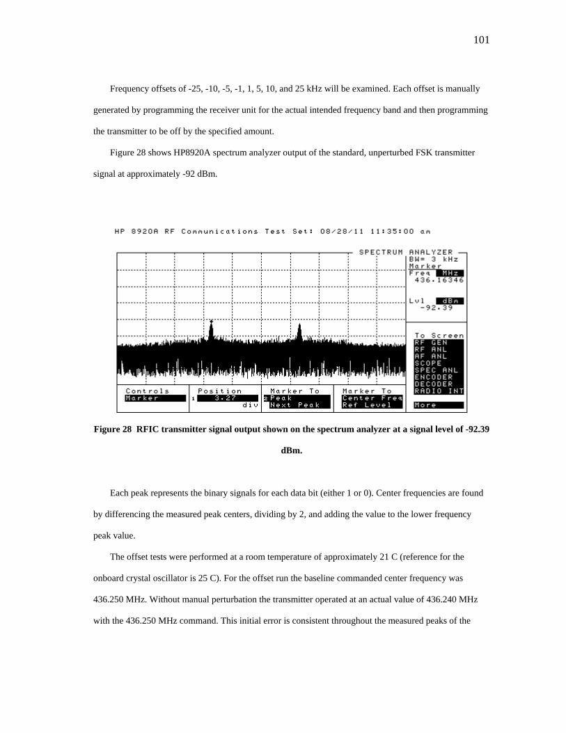
101
Frequency offsets of -25, -10, -5, -1, 1, 5, 10, and 25 kHz will be examined. Each offset is manually
generated by programming the receiver unit for the actual intended frequency band and then programming
the transmitter to be off by the specified amount.
Figure 28 shows HP8920A spectrum analyzer output of the standard, unperturbed FSK transmitter
signal at approximately -92 dBm.
Figure 28 RFIC transmitter signal output shown on the spectrum analyzer at a signal level of -92.39
dBm.
Each peak represents the binary signals for each data bit (either 1 or 0). Center frequencies are found
by differencing the measured peak centers, dividing by 2, and adding the value to the lower frequency
peak value.
The offset tests were performed at a room temperature of approximately 21 C (reference for the
onboard crystal oscillator is 25 C). For the offset run the baseline commanded center frequency was
436.250 MHz. Without manual perturbation the transmitter operated at an actual value of 436.240 MHz
with the 436.250 MHz command. This initial error is consistent throughout the measured peaks of the
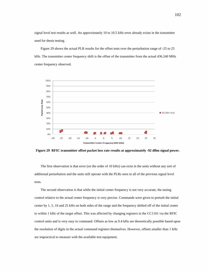
102
signal level test results as well. An approximately 10 to 10.5 kHz error already exists in the transmitter
used for thesis testing.
Figure 29 shows the actual PLR results for the offset tests over the perturbation range of -25 to 25
kHz. The transmitter center frequency shift is the offset of the transmitter from the actual 436.240 MHz
center frequency observed.
Figure 29 RFIC transmitter offset packet loss rate results at approximately -92 dBm signal power.
The first observation is that error (on the order of 10 kHz) can exist in the units without any sort of
additional perturbation and the units still operate with the PLRs seen in all of the previous signal level
tests.
The second observation is that while the initial center frequency is not very accurate, the tuning
control relative to the actual center frequency is very precise. Commands were given to perturb the initial
center by 1, 5, 10 and 25 kHz on both sides of the range and the frequency shifted off of the initial center
to within 1 kHz of the target offset. This was affected by changing registers in the CC1101 via the RFIC
control units and is very easy to command. Offsets as low as 0.4 kHz are theoretically possible based upon
the resolution of digits in the actual command registers themselves. However, offsets smaller than 1 kHz
are impractical to measure with the available test equipment.

103
The third observation is that the PLR response over the entire 50 kHz range is very flat and very low
(less than 10% loss rate). For a given signal power the RFIC units are very tolerant of transmitter center
frequency offsets. The 50 kHz range shown encompasses the same magnitude of a combined predicted
Doppler and temperature effects on a transmitter. For all intensive purposes the packet statistics are
unaffected by the tested shifts.
It appears that it would unlikely that an RFIC unit operating in FSK mode with the channel bandwidth
programmed (approximately 406 kHz) would have to be tuned for Doppler shift aft all, provided that the
host spacecraft is thermally balanced. By this result the spirit of requirement RF-6 has been met.
To the letter of the law, however, frequency control must be established. The results demonstrate that
it has been. Given an understanding of the true unperturbed transmitter center frequency, the transmitter
center has been controlled down to 1 kHz of tuning. The control capability is functionally present and
available if offset errors were to build up.
The combination of tuning control and wide tolerance makes for a very robust result because the
anticipated frequency tolerance (at least 25 kHz to either side of a center band, perhaps more) is
significantly larger than the available control steps. This provides a very large amount of flexibility to
catch signal even if additional, unanticipated errors occur.
F. Summary
The array of PLR tests show that signal levels approximating those expected at elevations from zenith
to ~25 degrees above the horizon can be transmitted with loss rates of 20% or less for a 350 km orbit.
Given a first generation operational concept with packet feedback and transit times, data rates of 57 to
85 kbps appear possible to achieve with the RFIC units. A mature system with sophisticated error checks
and minimized overhead could theoretically achieve rates approaching 112 kbps.
From a standpoint of frequency control the unit has demonstrated tolerance of transmitter center
frequency errors of up to +/-25 kHz. Tuning resolution up to 1 kHz has also been demonstrated.
104
The RFIC radios exhibit wide tolerance and relatively narrow frequency control. The results give
confidence that Doppler shift, thermal and tuning errors can be effectively overcome and in some cases
ignored operationally with the given preliminary design.
Weaknesses were identified in measurement capability and test setup understanding. Noise powers are
not expected to be strong enough to impair link estimates, but a full test featuring a verifiable noise
simulation is highly desired. Such a test should be implemented to promote full confidence in the system.
Similarly, unexpected variations in PLR performance were observed during tests taken during
different weeks. Tests do indicate that the test data handling system is likely not at fault. However,
something remains unknown in the RFIC system itself or the associated test and simulation hardware.
There is a risk that the lower ranges of elevation required to meet RF-8 cannot be met with the current
design. There are options to mitigate this, but more definitive testing must be undertaken to understand
and account for the variance.
It is hoped that AggieSat Lab’s NASA partnerships can be leveraged to complete noise testing and to
help understand performance variation in the RFIC system and test arrangement. Discussions are
underway and AggieSat Lab’s partners think they have equipment available to answer these questions.
This development has been undertaken without extensive RF engineering experience and with
borrowed and inherited test equipment. These limitations have been highlighted by the gaps remaining in
the original test plan and questions remaining in the verification process. Despite this, a great deal of
positive data has been obtained that does indicate the RFIC system can be capable of the intended
operations.
The data rates of the unit are in desired ranges, the unit is very controllable, and very well understood
from a design standpoint. The major high level question that remains from this PLR testing is if and how
much additional margin must be added to the preliminary design to definitively close the link at all
elevation ranges. Even if some margin is determined to be required, there is no indication that the iteration
process needed to add said margin is outside of the realm of possibility.
105
X. PROXIMITY OPERATIONS
The balance of this thesis has been devoted to the problems and specifics of downlink operations.
From the beginning the problems of downlink operations have provided the motivation for the hardware
development. The genesis of the project itself derives from the lackluster performance of the downlink
system onboard AggieSat2. The most basic goal underlying the requirements is a strong personal desire to
attack everything that was wrong with AggieSat2’s communications system.
To date there has not been a significant development effort spent upon a proximity operations version
of the system. A proximity operations version of the RFIC system would be designed to operate from
meters to tens of kilometers to transmit data between formation flying spacecraft. This is particularly
useful for the ARD objectives at AggieSat Lab.
Proximity operations were included in requirements RF-8 and RF-9 because significant utility can be
extracted from the basic hardware. A proximity operations variant does not require an amplifier to obtain
useful ranges. The concept work featured here specifies 250 kbps performance at 10 km without an
external amplifier.
Without an amplifier the hardware is incredibly compact. The initial downlink design without
amplification equipment is barely 4” x 2”. Time and practice with surface mount soldering techniques and
packaging can reduce this significantly, especially if the CC1101 chip itself is migrated from the
CC1101EMK to the control unit board.
The real development question that remains is how to develop a half duplex packet handler than can
accept packet traffic in two directions. The efforts to develop, implement, and test the downlink portion of
the hardware have simply taken the available research time from efforts to develop an alternate packet
system for proximity operations.
The packet handler for the downlink system can be improved, but itself was not difficult to develop
for the first time. It is not anticipated that a herculean effort will be required to spin off a proximity
operations data system.

106
AggieSat Lab will continue to develop the RFIC system and is already pursuing capabilities with
partners to answer remaining questions from downlink system testing. Any lab members or future
developers interested in the proximity operations application will have the wealth of experience, design
documentation, and test data from the downlink system to start with. The CC1101 and PIC18F4520 chip
systems have been easy to work with in development and have not provided insurmountable functional
challenges.
107
XI. MINIMUM SHIFT KEYING VERSUS FREQUENCY SHIFT KEYING
The preliminary design presented utilizes Frequency Shift Keying modulation to create radio signals.
Two closely spaced carriers are implemented that modulate a zero or a one. Minimum Shift Keying is an
alternative method, previously defined, that uses multiple carrier phases to send pairs of bits in a much
smaller bandwidth on one narrow signal peak.
It was suggested at the committee level that MSK modulation could be a beneficial alternative to
FSK.
Minimum shift keying for the CC1101 is a variant of Quadriphased Phase Shift Keying (QPSK)
shaped by a sinusoid [111]. QPSK itself is a variant of Binary Phase Shift Keying (BPSK). In BPSK,
rather than using two frequencies, the phase of the signal is shifted by 180 degrees to differentiate between
a 1 or 0 in the data [128]. In QPSK the modulator takes advantage of the fact that waveforms can be
decomposed into completely orthogonal components. Each component is modulated by binary phase
changes and combined into one carrier signal resulting in four phase combinations. Each variation
represents a symbol pair of 00, 11, 10, or 01. The symbol rate is half the data rate because pairs of bits are
transmitted simultaneously for each component combination. [128]. MSK shapes the result by combining
a sinusoidal waveform and can achieve more efficient band usage by controlling side lobes of transmission
[128].
MSK offers the promise of smaller bandwidth which makes coordination with amateur radio operators
on UHF easier. The savings in symbol rate may also reduce the required signal to noise ratio required to
achieve the same Bit Error Rate (BER). Wertz suggests MSK only requires ~11dB of gain over noise as
opposed to nearly 15 to achieve a BER of 10^-7 [116]. Sklar suggests that MSK BER’s of 10^-7 can be
achieved by only 12 dB of gain over noise [128]. Sklar only quotes BER rates for BPSK but demonstrates
how QPSK and BPSK share the same Bit Error Probability because a QPSK signal contains two
orthogonal BPSK signals at half the rate and half the power of the single BPSK signal [128]. MSK, as
stated before, is a shaped QPSK signal and also shares the same BER performance [128].

108
The potential bandwidth and noise performance savings can be useful, but it is not known if the
savings are required. There are other simpler margin alternatives, but this could also be considered a way
to obtain more link margin at lower elevations.
Despite the benefits, one should consider that the frequency error tolerance of the current design using
FSK may be a function of the wide bandwidth of the receiver filter. The filter is approximately 406 kHz
wide, meaning anticipated Doppler effects can only shift signal by 2% of the bandwidth.
An MSK variant of the RFIC system transmitter has been run, but the required settings have not been
fully determined to complete successful packet transmissions. Figure 30 shows an early FSK transmission
on the spectrum analyzer scope (at much higher signal power than previous examples for testing) and
Figure 31 shows the same for an MSK modulation run. The MSK is a narrower signal overall. If the
development is of future interest a starting code for MSK using the PIC18F4520 microcontroller is
available.
Figure 30 Spectrum analyzer output of a CC1101 using FSK modulation.
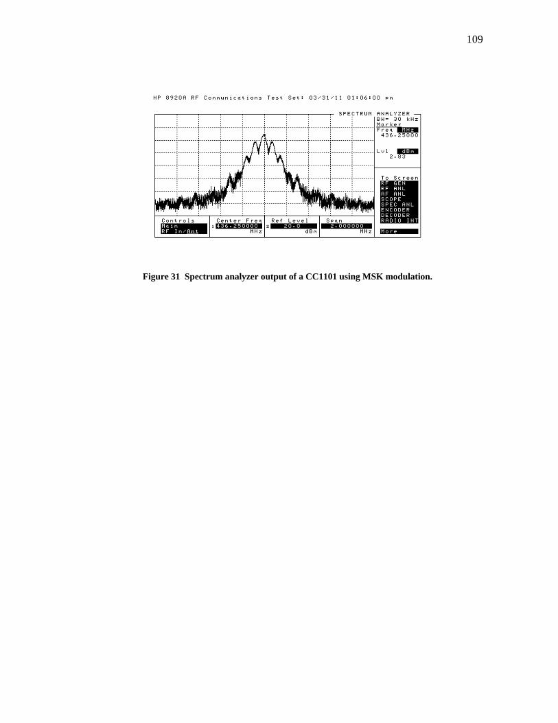
109
Figure 31 Spectrum analyzer output of a CC1101 using MSK modulation.

110
XII. CONCLUSION
In the coming months and years AggieSat Lab will be undertaking ambitious missions that will stretch
commercial off the shelf hardware, student engineers, and resources beyond experiences of the past. A
wealth of data including imagery, navigation data, and others will have to be captured and downloaded to
verify all the objectives for ARD demonstrations as outlined by AggieSat, the University of Texas, and
NASA partners.
Other organizations and missions will require improved data download capability as well. Ever
expanding capability itself will also help spawn other missions that have not yet been imagined for small
spacecraft. The community needs alternatives to low performance amateur equipment and high
performance, but high expense commercial solutions that are available and in use today.
Promising alternatives are being developed by other organizations. Progress made by the original
GeneSat-1 team with wireless data modems has generated a short, but intense flight history and many of
the early problems with this method may yet be solved. Another particularly promising alternative is the
software defined radio in development at Southwest Research Institute in San Antonio, Texas. SwRI’s
efforts will be welcome if the radio performs well in flight test and can be offered for relatively low cost to
small organizations with small satellite missions.
Time will tell if these alternatives can come to full fruition. In the mean time the RFIC based system
presented promises to be an equally useful alternative. The RFIC system is not the highest performing
alternative available, but the RFIC system offers control and accessibility to small organizations without
well developed radio engineering experience.
Ideally, the best solution would be incredibly robust and fast. In some cases a fast solution exists, but
does not prove to be reliable operationally. This was the case with AggiSat2’s modem based system. The
speed could not be leveraged because operational problems were not solved and the useful communication
time was very low. In other cases a low performance system that can be operated every day can get a lot of
111
data down. In that flight experience even a 1,200 bps or 9,600 bps amateur radio system could have gotten
more data down if it could have been operated reliably over the course of the 230 day mission.
The RFIC solution bridges this gap. The demonstrated performance is approximately 55 to 85 kbps in
its basic form, with potential to expand this over 100 kbps. With a little bit of development the system can
offer speeds ten times greater than the run of the mill 9,600 bps amateur packet system. All of this was
developed in a year’s time, by a developer with no practical electrical or software engineering experience,
and features a very approachable interface that is simple to use. The ease of interface control, in particular
tuning capability, stands a great chance of tackling the operational problems that AggieSat has
experienced in the past.
This thesis follows the structure of a small, but orderly systems engineering effort. A set of
requirements based on institutional experiences on a previous spacecraft mission has led to a concept
development, prototype hardware, analysis, and a head start in verification testing. It is hoped that this
thesis can be used as an example by other student engineers to help develop other hardware for other
applications. It is also hoped that the internal documentation submitted to the AggieSat configuration
management system can be used to press forward with the RFIC radio development and prepare it for a
flight test and usage.
A. Requirements Evaluation
Each requirement will be evaluated in turn at the conclusion of the thesis.
1. RF-1: Develop a University Class Radio System Building Block Using RFICs.
RF-1 has been met. A radio system building block has been completed and functionally tested that
uses RFIC hardware to meet the proposed applications.
112
2. RF-2: The Radio System Must Utilize Bands That are Legally Available to AggieSat or Can Be
Licensed for Use and Comply With Regulations Pertaining To Those Bands.
RF-2 has been met. The preliminary RFIC unit design operates on the UHF band in the amateur
portion of that band. All testing has been conducted by a licensed control operator and call sign
information has been embedded in the test data.
3. RF-3: Characterize the Building Block in Relation to Mass, Power, Volume, Thermal, Vacuum, and
Radiation Performance.
RF-3 has not been fully met. Information is available in the concept section for mass and power
estimates. RFIC hardware exists in the lab that can be measured as well, but the specified amplifier unit
has not been acquired to determine total mass and system power draw. Thermal and vacuum testing has
been deferred until a unit is being prepared along with a flight spacecraft. AggieSat programs typically
perform this type of testing with a fully integrated spacecraft system because of time and cost constraints
of this testing. Radiation testing may or may not be an option during future flight integration.
4. RF-4: Capture the Requirements, Design, Results, and Lessons Learned for Further RF Component
Development to Improve Lab Satellite Design Capabilities.
RF-4 has been met. A draft set of full design documentation is available for the AggieSat Lab
configuration management process. The thesis manuscript captures the history of the development effort
and discussion of lessons learned. All test data including packet error rate data, oscilloscope charts,
spectrum analyzer charts, and functional test milestones are part of the AggieSat Lab’s resources.
Example hardware is also available, along with the documentation, to provide a starting point for
continued development.

113
5. RF-5: The System Must be Designed to Operate in a Low Earth Orbit (LEO) Environment for at Least
6 Months (Thermal, Vacuum, Radiation).
RF-5 has not been met. Most concerns relating to space environment issues will be handled by
standard practices and controls when an RFIC flight unit is integrated for a flight test or use. These
practices include, but are not limited to material control, coatings, and treatments to prepare electronics for
flight. As mentioned before thermal and vacuum testing has been deferred until a unit is being prepared
along with a flight spacecraft and an integrated set of tests can be performed.
6. RF-6: The Developed Radio System Must Be Capable of Being Frequency Agile as Defined by
Objective 1 to Address Problems Related to Space Operations.
RF-6 has been met. Objective 1 requires that agility and error tolerance be implemented with the
intent of counteracting Doppler shift and other frequency errors. The RFIC preliminary design has been
shown in initial testing to have a frequency error tolerance at least as wide as the predicted magnitude of
frequency errors in analysis (approximately 25 kHz on either side of center). The RFIC preliminary design
also features frequency tuning as part of the as built interface that can control the center band of the radio
units at a resolution well within the tolerance band.
7. RF-7: The Developed Radio System Must Have an Average Throughput of 38,400 bps or Better.
RF-7 has been met. The as built RFIC preliminary design has been shown to be capable of
approximately 55,000 -85,000 bps. This performance has been achieved within the limitations of the
packet loss statistics of the hardware and timing and delays associated with the packet handler system and
proposed operations concept for downlink.
With time and effort a system capable of operations between 85,000 and 112,000 bps should be
possible.
114
8. RF-8: The Developed Radio System Must Have a Broadcast Power to Allow Downlink Segments to
Close Link at 10 Degree Elevation for a 350 km Orbit.
RF-8 has not been fully met. Signal levels have been tested approximating elevations down to 25
degrees with packet loss rates less than 20%. Variations discovered in the preliminary testing captured
here have not yet been understood. There is no reason to believe RF-8 cannot be met after further data is
collected, but the data must be obtained, processed, and the preliminary design and possibly the test setup
itself must be iterated. Discussions are underway with NASA to collect better test data.
9. RF-9: The Developed Radio System Must Be Capable of Communication to a Minimum Range of 0 to
1 km.
RF-9 has not been met. The link budgets give confidence that this range can easily be met since it is
so short comparted to downlink ranges. The proximity operations system should be prototyped to fully
meet this requirement.
10. RF-10: The Developed Radio System Must Be Capable of Two Way, Half Duplex, Data Operations in
Proximity Operations Applications.
RF-9 has not been met. The proximity operations variant of the preliminary design has been studied at
the concept level only. Signal level requirements are less constraining for this application and the Doppler
shift and tuning requirements are not applicable. For this reason it is expected this application can be
developed at less risk than the downlink system. The only remaining action item for this requirement is to
formally develop a packet handler system for this application.
11. Future Requirement Work
The pending requirements that remain to be met require additional system testing (RF-3, 5), better
radio frequency measurement (RF-8), and more time to complete development (RF-9, 10). None of the
pending requirements have failed outright and there are no indications that these additional requirements
cannot be met with further development.
115
The completed requirements and available test data suggest that the RFIC preliminary design can
offer the desired performance and controllability for future spacecraft applications.
B. Verification Plan and Future Work
1. Verification Plan Status
The preliminary design and all design verification steps outlined in Table 10 of the Verification Plan
section have been completed. This is captured by the thesis and associated internal documentation.
Phase 1 analysis has also been completed and is captured in this manuscript. The results from the
analysis have assisted greatly with planning and execution of the prescribed verification testing.
A majority of Phase 2 testing has been completed. Basic functional testing for the first batch of units
is completed successfully and filed with internal documentation. Packet loss rate testing with offsets has
been completed and there is high confidence in frequency controllability and tolerance.
Oscilloscope test data is available and the timing of the preliminary design unit is well understood.
Initial packet loss testing featuring signal level sweeps has only been partially completed. The
variance in performance on the lower end of the desired test range is not understood at this time. The data
collected at the higher end of the signal level range is positive and indicates that the system can be made to
work at the lower ranges with modification if the variance is attributed to the RFIC hardware itself. There
is a possibility this variance is contained to the test setup rather than the R FIC system. This will be
explored with focused testing prescribed as part of the next immediate development phase.
The initial signal level tests also did not feature an external noise simulation. This was because the
generated noise could not be measured and verified for the tests with the available equipment.
2. Future Noise Testing
The future work plan will include noise testing performed in conjunction with NASA partners and
equipment. This plan is already under discussion. Tests should be conducted as planned, but include
NASA capabilities to verify the noise generation for the test.
116
3. Focused Re-testing of the Initial Signal Level Tests
It is recommended that the immediate body of future work also include a focused re-test of the signal
level results using NASA partner expertise and equipment. This effort should replicate the testing featured
in the Master’s thesis in an attempt to isolate the origin and cause of the performance variance.
Determination of the root cause of this variance will assist other groups without access to alternatives
for testing equipment to proceed with their own RFIC development efforts. If the answer lies in the
hardware itself, margin must be added to the system. If it lies in the test equipment, lessons learned can be
added to the body of knowledge to assist future developments.
4. Verification Phase 3
Phase 3 testing includes integrated functional testing and future environmental testing in addition to
the re-tests for discoveries made during this research.
Integrated functional testing requires a candidate spacecraft and associated command and data
handling system so that final interface issues can be worked out and a preliminary flight test can be
conducted. All of these tests should be pursued proactively if and when a plan for a flight test of the RFIC
system can be arranged.
C. Lessons Learned
A few high level lessons learned have been obtained that are outside of the realm of the detail analysis
and re-testing that has been suggested.
The first major lesson is for other students, especially those studying aerospace and mechanical
engineering. They should understand that processes common to computer scientists, computer engineers,
and electrical engineers are not nearly as difficult as they can sometimes seem. The problems of software
and electronic hardware development are by no means trivial, but the RFIC project itself is an example of
a relatively fast development of an electrical and software spacecraft system by a non-expert in the related
fields.
117
The second major lesson learned is that the RFIC component field is very large and diverse. The trade
studies exhibited by the thesis only scratch the surface of possibilities in the hardware offered by
manufacturers. Strategic decisions based on requirements were made to control the scope of the project
throughout its development. Other developers and engineers should take this thesis as an example and feel
free to explore devices that were not covered here.
Many of the more exotic modulation schemes, software options, and frequency bands could offer
more performance gains. There are a great many RFIC chips in production at low cost.
Finally, the difficulty of RF measurement and test should not be underestimated. The first round of
RFIC preliminary design testing ran into a distinct problem measuring low noise levels, and found
variance in signal level test results that are not yet understood. These are areas where a combination of
experience and quality test equipment would be very applicable. This highlights the difficulty that small
organizations have had with radio system development in the past.
A closing thought is that the next major effort in spacecraft communications design for small satellites
should not be focused on flight hardware, but on measurement equipment. A breakthrough in high quality
but affordable radio test equipment would be a very welcome addition to the field.
D. Final Evaluation
The initial project questions remain. Can a useful spacecraft communications building block be
constructed from commercially available Radio Frequency Integrated Circuits and improve upon overall
data rate performance, control, and robustness for downlink and proximity operations applications?
The answer is yes. In a years time a radio system that meets most of the original performance targets
has been constructed by a non-expert and tested. Lingering questions in performance can be tested and
will be soon through the available partnerships to AggieSat. None of the problems experienced indicate
that the final questions will not be answered, addressed, and the unit made available for small satellite
operations in the near future.
Can this system be designed, built and captured using and improving upon student satellite design and
engineering capabilities?

118
The answer is also yes. The entire effort captured by this thesis has been undertaken with the tools and
methods available and taught at AggieSat Lab. Real hardware has been made available with all the
associated design documentation for use on small spacecraft at the student design level. The available
hardware, test information, control of design, and understanding is an order of magnitude more complete
than that of the communications system that was implemented on AggieSat2.

119
REFERENCES
[1] Sweeting, M.N., “UoSAT microsatellite missions,” Electronics and Communications Engineering
Journal, Vol. 4, No. 3, June 1992, pp. 141-142.
[2] Foust, J., “Emerging Opportunities for Low-Cost Small Satellites in Civil and Commercial Space,”
24th Annual USU Conference on Small Satellites, Logan, UT, AIAA Paper SSC10-IV-4, Aug. 2010,
pp. 1-2.
[3] Bille, M., Kolodziejski, P., and Hunsaker, T., “Distant Horizons: Smallsat Evolution in the Mid-to-far
Term,” 25th Annual USU Conference on Small Satellites, Logan, UT, AIAA Paper SSC11-IV-1, Aug.
2011, pp. 1-4.
[4] Swartwout, M., “The First One Hundred University-class Spacecraft, 1981-2008,” IEEE A&E
Systems Magazine, Vol. 24, No. 3, March 2009, pp. A-1 – A-4, A-9.
doi: 10.1109/MAES.2009.4811089
[5] Puig-Suari, J., Turner, C., and Twiggs, R., “CubeSat: The Development and Launch Support
Infrastructure for Eighteen Different Satellite Customers on One Launch,” 15th Annual USU
Conference on Small Satellites, Logan, UT, AIAA Paper SSC01-VIIIb-5, Aug. 2001.
[6] “Information about the Cubesat Program,” Cubesat Information [online database], URL:
http://www.amsat.org/amsat-new/satellites/cubesats.php [cited 28 May 2011].
[7] Friedman, A., et al., “ASUSat1: Low-cost, Student-designed Nanosatellite,” AIAA Journal of
Spacecraft and Rockets, Vol. 39, No. 5, 2002, pp. 740-748.
[8] “Subsystems,” FASTRAC: Formation Autonomy Spacecraft with Thrust, Relnav, Attitude, &
Crosslink [project webpage], URL: http://fastrac.ae.utexas.edu/our_satellites/subsystems.php [cited 31
May 2011].
[9] Horan, S., and Alvarez, L., “Preparing a COTS Radio for Flight – Lessons Learned from the 3 Corner
Satellite Project,” 16th Annual USU Conference on Small Satellites, Logan, UT, AIAA Paper SSC02-
X-4, Aug. 2002, pp. 1-4.

120
[10] Swartwout, M., “The promise of innovation from university space systems: are we meeting it?,” The
Space Review Essays and CommentaryAbout the Final Frontier [online periodical], URL:
http://www.thespacere0view.com/article/1490/1 [cited 28 May 2011].
[11] Hunyadi, G., Ganley, J., Peffer, A., and Kumashiro, M., “The University Nanosatellite Program: An
Adaptable, Responsive, and Realistic Capability Demonstration Vehicle,” 2004 IEEE Aerospace
Conference, IEEE, Big Sky, MT, 2004, pp. 2850, 2855, 2856.
doi: 10.1109/AERO.2004.1368091
[12] Reed, H., et al., “AggieSat Lab: Nanosats and Cubesats,” Proceedings of the 32nd Annual AAS Rocky
Mountain Guidance and Control Conference, AAS 09-081, Vol. 133, For AAS by Univelt, San
Diego, 2009, p. 547.
[13] Graves, J.T., and Reed, H., “The AggieSat2 Student Satellite Mission,” 50th AIAA Aerospace
Sciences Meeting, AIAA, Nashville, TN, 2012. (to be published)
[14] Graves, J.T., et al., “The Role of Responsive Architectures in Educating Students,” 8th Responsive
Space Conference, Los Angeles, CA, AIAA Paper AIAA-RS8-2010-1003, Mar. 2010, p. 5.
[15] Davidoff, M., The Radio Amateur’s Satellite Handbook, The American Radio Relay League,
Newington, CT, 2003, Chaps. 5, 9.
[16] Bruninga, B., Orloff, B., Kinzbrumer, E., Rose, J., and Schwarzer, S., “RAFT Radar Fence
Transponder Critical Design Review,” RAFT Satellite Project [online presentation], URL:
http://www.usna.edu/Users/aero/bruninga/craft/RAFT_USNA_CDR_ver6.ppt [cited 31 May 2011].
[17] Lee, E.P., et al., “The *.Sat CubeSat Bus: When Three Cubes Meet,” Space Systems Development
Laboratory, Stanford University, AIAA SSC05-VI-4, Stanford, CA, 2005, p. 17.
[18] Clason, R., Matalavage, J., and Tsuji, L., “NASA Ground Network Overview and Interoperability
Opportunities,” Near Earth Networks Conference 2003 [online presentation], URL:
http://rapweb.jpl.nasa.gov/NASA_NOAA_JPL/GN%20Wallops%20Conference%20presentation%20
V2%202003%200626.pdf [cited 10 October 2011].
[19] “Three Newly Designed Tracking and Data Relay Satellites To Help Replenish Existing On-Orbit
Fleet,” NASA FS-2001-9-025-GSFC, 2001.

121
[20] Hodges, L., and Woll, R., “Air Force Satellite Control Network (AFSCN) Support for Operational
Responsive Space (ORS),” 6th Responsive Space Conference, Los Angeles, CA, AIAA Paper RS6-
2008-1006, Apr. 2008.
[21] “Spread Spectrum,” Microhard Systems Inc.; Design and Manufacture of Long Range Robust
Wireless Data Equipment [online product page], URL: http://www.microhardcorp.com/license-free-
spread-spectrum.php [cited 31 May 2011].
[22] “ZigBee and RF Modules,” Digi Making Wireless M2M Easy [online product page], URL:
http://www.digi.com/products/wireless-wired-embedded-solutions/zigbee-rf-modules/ [cited 31 May
2011].
[23] “Wireless and Wired Communications Built-in,” CubeSat Kit – Communications [online product
page], URL: http://www.cubesatkit.com/content/electronics/comms.html [cited 28 May 2011].
[24] “L-3 Communication Systems – West,” L-3 Communications Holdings, Inc. [online product page],
URL: http://www.l-3com.com/csw/ [cited 28 May 2011].
[25] “S-Band Transceiver,” Comtech AeroAstro [online product page], URL:
http://www.aeroastro.com/index.php/space-products-2/s-band-radio [cited 31 May 2011].
[26] “S-Band Downlink Transmitter,” Surrey Satellite Technologies LTD [online product datasheet], URL:
http://www.sstl.co.uk/Downloads/Datasheets/S_Band-Transmitter_0013577_603 [cited 1 June 2011].
[27] “radio frequency integrated circuit,” Encyclopedia Britannica [online encyclopedia], URL:
http://www.britannica.com/EBchecked/topic/1069068/radio-frequency-integrated-circuit [cited 1 June
2011].
[28] “Wireless and RF,” Maxim Integrated Products [online product page], URL: http://www.maxim-
ic.com/products/wireless/ [cited 18 September 2010].
[29] “Smart RF,” Atmel Corporation [online product page], URL:
http://www.atmel.com/products/smartRF/default.asp?family_id=651&source=global_nav [cited 18
September 2010].

122
[30] “ISM Band Transceivers,” RF Micro Devices [online product page], URL:
https://estore.rfmd.com/RFMD_OnlineStore/Browse.aspx?Family=ISM%20Band%20Transceivers
[cited 18 September 2010].
[31] “RF/IF and ZigBee Solutions,” Texas Instruments Incorporated [online product page], URL:
http://focus.ti.com/paramsearch/docs/parametricsearch.tsp?family=analog&familyId=935&uiTemplat
eId=NODE_STRY_PGE_T [cited 18 September 2010].
[32] Kramer, H.J., and Cracknell, A.P., “An overview of small satellites in remote sensing,” International
Journal of Remote Sensing, Vol. 29, No. 15, 10 Aug. 2008, pp. 4286-4337.
[33] “The Radio Amateur Satellite Corporation,” AMSAT [organization webpage], URL:
http://www.amsat.org/amsat-new/ [cited 23 June 2011].
[34] “The Next-Generation of Spacecraft Products is Here Now,” SpaceQuest, Ltd. [product webpage],
URL: http://www.spacequest.com/product.php [cited 17 June 2011].
[35] Mas, I.A., and Kitts, C.A., “A Flight-Proven 2.4GHz ISM Band COTS Communications System for
Small Satellites,” 21st Annual AIAA/USU Conference on Small Satellites, Logan, UT, AIAA Paper
SSC07-XI-11, Aug. 2007.
[36] “PARADIGM,” Satellite Detail-PARADIGM [online database], URL: http://www.amsat.org/amsat-
new/satellites/satInfo.php?satID=125&retURL=satellites/all_oscars.php [cited 22 June 2011].
[37] “PARADIGM,” PARADIGM [project website], URL:http://paradigm.ae.utexas.edu/ [cited 22 June
2011].
[38] “NRL’s ANDE-2 Launches Aboard STS-127,” NRL Press Release [online press release], URL:
http://www.nrl.navy.mil/pao/pressRelease.php?Y=2009&R=39-09r [cited 22 June 2011].
[39] “Castor,” Satellite Detail-Castor [online database], URL: http://www.amsat.org/amsat-
new/satellites/satInfo.php?satID=122&retURL=satellites/all_oscars.php [cited 18 June 2011].
[40] “Pollux,” Satellite Detail-Pollux [online database], URL: http://www.amsat.org/amsat-
new/satellites/satInfo.php?satID=123&retURL=satellites/all_oscars.php [cited 18 June 2011].
[41] Angulo, M., et al., “Development of the MicroSat Programme at INTA,” Small Satellites for Earth
Observation, edited by R. Sandau et al., Springer Science+Busness Media B.V., 2008, pp. 41, 50-51.

123
[42] Subramanian, T.S., “Launch campaign apace for lift-off of PSLV-C14,” The Hindu [online
periodical], URL: http://www.hindu.com/2009/09/13/stories/2009091356431800.htm [cited 22 June
2011].
[43] Kayal, H., Baumann, F. Briess, K., and Montenegro, S., “BEESAT: A Pico Satellite for the On Orbit
Verification of Micro Wheels,” 3rd International Conference on Recent Advances in Space
Technologies, IEEE, Istanbul, 2007. pp. 497-502.
doi: 10.1109/RAST.2007.4284041
[44] “ITUpSAT1 Project,” Projects – ITU Space Systems Design and Test Laboratory [project website],
URL: http://usl.itu.edu.tr/tr/projeler.php [cited 15 June 2011].
[45] “ITUpSAT1,” Satellite Detail-ITUpSAT1 [online database], URL: http://www.amsat.org/amsat-
new/satellites/satInfo.php?satID=127&retURL=satellites/all_oscars.php [cited 18 June 2011].
[46] “SwissCube,” Swiss Cube | The First Swiss Satellite [project webpage], URL:
http://swisscube.epfl.ch/ [cited 18 June 2011].
[47] Schmidt, M., Karthik, R., Kurz, O., Buseh, S., and Schilling, K., “Attitude Determination for the
Pico-Satellite UWE-2,” Proceedings of the 17th World Congress, The International Federation of
Automatic Control, Seoul, 2008, pp. 14036-14037.
[48] “PSLV-C15,” Indian Space Research Organization [online datasheet], URL:
http://www.isro.org/pslv-c15/pdf/CARTOSAT-2B-brochure.pdf#PSLV-C15 [cited 22 June 2011].
[49] “Team STUDSAT,” Team STUDSAT [project webpage], URL: http://www.teamstudsat.com/index-
2.html [cited 23 June 2011].
[50] “TIsat-1,” Project TIsat-1 Index [project webpage], URL:
http://www.spacelab.dti.supsi.ch/tiSat1Indice.html [cited 23 June 2011].
[51] “FASTRAC 1,” Satellite Detail-FASTRAC 1 [online database], The Radio Amateur Satellite
Corporation, URL: http://www.amsat.org/amsat-
new/satellites/satInfo.php?satID=131&retURL=satellites/all_oscars.php [cited 9 June 2011].

124
[52] “FASTRAC 2,” Satellite Detail-FASTRAC 2 [online database], The Radio Amateur Satellite
Corporation, URL: http://www.amsat.org/amsat-
new/satellites/satInfo.php?satID=132&retURL=satellites/all_oscars.php [cited 9 June 2011].
[53] Minelli, G., et al., “O/OREOS Nanosatellite: A Multi-Payload Technology Demonstration,” 24th
Annual AIAA/USU Conference on Small Satellites, Logan, UT, AIAA Paper SSC10-VI-1, Aug.
2010.
[54] “O/OREOS,” Satellite Detail-O/OREOS [online database], URL: http://www.amsat.org/amsat-
new/satellites/satInfo.php?satID=134&retURL=satellites/all_oscars.php [cited 28 May 2011].
[55] “Mission Overview,” Radio Aurora Explorer Bold Science, Bold Flight [project website], URL:
http://rad.engin.umich.edu/?page_id=291 [cited 16 June 2011].
[56] “Spacecraft Specifications,” RAX [project website], URL: http://rax.engin.umich.edu/wp-
content/uploads/2010/09/SpacecraftSpecifications.pdf [cited 23 June 2011].
[57] “About Amateur Radio Services,” FCC: Wireless Services, URL:
http://wireless.fcc.gov/services/index.htm?job=about&id=amateur [cited 6 June 2011].
[58] Bedell, P., Wireless Crash Course, McGraw-Hill, Blacklick, OH, 2001, Chap. 24.
[59] Ackermann, J., “Why We’re Stuck at 1200 Baud,” Febo [personal website], URL:
http://www.febo.com/packet/cheap-9k6/why.html [cited 31 May 2011].
[60] “KWM-9612+ Wireless Modem,” Kantronics Digital Data Radio Communications GPS Tracking
[product webpage], URL: http://www.kantronics.com/products/kwm9612.html [cited 23 June 2011].
[61] “The NEW WA4DSY 56kb RF Modem,” PacComm [project webpage], URL:
http://paccomm.com/56kb.html [cited 23 June 2011].
[62] Baker, K., and Jansson, D., “Space Satellites from the World’s Garage – The Story of AMSAT,”
Proceedings of the IEEE 1994 National Aerospace and Electronics Conference, Vol. 2, IEEE,
Dayton, 1994, pp. 1174, 1181.
doi: 10.1109/NAECON.1994.332909
[63] Ford, S., “An Amateur Satellite Primer,” QST, Vol. 84, No. 4, 2000, pp. 36-41.
[64] Wolfgang, L.D. (ed.), Now You’re Talking,, 5th ed., ARRL, Newington, CT, 2004, Chap. 9.

125
[65] Seguin, M., “The Amateur Satellite Resource Guide,” AMSAT [organization webpage], URL:
http://www.amsat.org/amsat-new/information/faqs/resguide.pdf [cited 24 June 2011].
[66] Rash, J., Parise, R., Hogie, K., Criscuolo, E., and Langston, J., “Internet Technology on Spacecraft,”
NASA Goddard Spaceflight Center, AIAA-2000-5295, 2000, pp. 1, 7-8.
[67] Wahl, Z.A., Walker, K.L., and Ward, J., “Modular and Reusable Miniature Subsystems for Small
Satellites: An Example Describing Surrey’s Nanosatellite S-Band Downlink,” 14th Annual
AIAA/USU Conference on Small Satellites, Logan, UT, AIAA Paper SSC00-X-4, Aug. 2000, pp. 2-3,
6.
[68] “Surrey Satellite Technology Ltd. (SSTL),” Surrey Satellite Technology Ltd. [company webpage],
URL: http://www.sstl.co.uk/ [cited 24 June 2011].
[69] Triharjanto, R.H., Hasbi, W., Widipaminto, A., Mukhayadi, M., and Renner, U., “LAPAN-
TUBSAT: Micro-Satellite Platform for Surveillance & Remote Sensing,” Proceedings of the 4S
Symposium: Small Satellites, Systems and Services, ESA SP-571, La Rochelle, 2004, pp. 4-5.
[70] Schulz, S., and Renner, U., “DLR-TUBSAT: A Microsatellite for Interactive Earth Observation,”
Technical University of Berlin, Institute of Aerospace, Berlin, Germany, 2000.
[71] Kim, H., Chung, T.J., Sung, N.H., and Lee, H.K., “Design Concept for Autonomous Operation of
KITSAT-3, an Experimental LEO Microsatellite,” Aerospace Conference Proceedings, Vol. 2, IEEE,
Big Sky, MT, 2000, p. 460.
[72] “BST: Home,” BST Berlin Space Technologies [company webpage], URL: http://www.berlin-space-
technologies.com/ [cited 19 June 2011].
[73] “SI Satrec Initiative,” Satrec Initiative [company webpage], URL: http://www.satreci.com/eng/ [cited
24 June 2011].
[74] Kuhn, W., Jeon, J., and Wong, K., “A Low-power, Radiation-tolerant, RFIC Micro-transceiver for
Space Applications,” Kansas State University Department of Electrical and Computer Engineering,
Manhattan, KS, 2007, pp. 1-2.

126
[75] Kuhn, W., Lay, N., and Grigorian, E., “A UHF Proximity Micro-Transceiver for Mars Exploration,”
Kansas State University, Manhattan, KS, 2006.
doi: 10.1109/AERO.2006.1655779
[76] Kuhn, W., Lay, N., and Grigorian, E.,“A Low-volume, Low-mass, Low-power UHF Proximity
Micro-Transceiver for Mars Exploration,” Kansas State University, Manhattan, KS, 2005.
[77] Rankin, D., and Kekez, D.D., “The CANX-2 Nanosatellite: Expanding the Science Abilities of
Nanosatellites,” 55th International Astronautical Congress 2004, Vancouver, BC, International
Astronautical Conference Paper IAC-04-IAA.4.11.6.04, Oct. 2004.
[78] Sarda, K., et al., “Canadian Advanced Nanospace Experiment 2 Orbit Operations: One Year of
Pushing the Nanosatellite Performance Envelope,” 23rd Annual AIAA/USU Conference on Small
Satellites, Logan, UT, AIAA Paper SSC09-IV-6, Aug. 2009, p. 5.
[79] Tuli, T.S., Orr, N.G., and Zee, R.E., “Low Cost Ground Station Design for Nanosatellite Missions,”
2006 AMSAT North American Space Symposium, San Francisco, CA, Oct. 2006.
[80] Narheim, B.T., et al., “A Norwegian Satellite for Space-based Observations of AIS in the High
North,” 21st Annual AIAA/USU Conference on Small Satellites, Logan, UT, AIAA Paper SSC08-III-
3, Aug. 2007, pp. 1-6.
[81] “S-Band Transmitter,” CubeSatShop [product webpage], URL:
http://www.cubesatshop.com/index.php?page=shop.product_details&flypage=flypage.tpl&product_id
=9&category_id=5&option=com_virtuemart&Itemid=67 [cited 1 July 2011].
[82] “Company Profile,” Innovative Solutions in Space [company website], URL:
http://www.isispace.nl/index.php?option=com_content&task=view&id=17&Itemid=32 [cited 1 July
2011].
[83] Ubbels, W.J., Verhoeven, C.J.M, Hamann, R.J., Gill, E., and Bouwmeester, J., “First Flight Results of
the Delfi-C3 Satellite Mission,” 22nd Annual AIAA/USU Conference on Small Satellites, Logan, UT,
AIAA Paper SSC08-X-7, Aug. 2008, pp. 1, 3.

127
[84] Sauer, C.D., Alvarez, J.L, Dickinson, J.R., Epperly, M.E., and Lecocke, M.B., “Reconfigurable,
Radiation Tolerant S-Band transponder for Small Satellite Applications,” 25th Annual AIAA/USU
Conference on Small Satellites, Logan, UT, AIAA Paper SSC11-XI-5, Aug. 2011, pp. 1-7.
[85] Tourrilhes, J., “Wireless LAN resources for Linux,” Wireless LAN Resources for Linux [company
webpage], URL: http://www.hpl.hp.com/personal/Jean_Tourrilhes/Linux/Linux.Wireless.modem.html
[cited 8 June 2011].
[86] Lathi, B.P., Modern Digital and Analog Communications Systems, 3rd ed., Oxford University Press,
Inc., New York, 1998, Chap. 9.
[87] “Space Test Program-H2-Microelectromechanical System-Based (MEMS) PICOSAT Inspector
(STP-H2-MEPSI),” NASA International Space Station [project webpage], URL:
http://www.nasa.gov/mission_pages/station/research/experiments/STP-H2-MEPSI.html [cited 22 June
2011].
[88] Helvajian, H., and Janson, S., Small Satellites: Past, Present, and Future, Aerospace Press, Los
Angeles, 2009, Chap. 20.
[89] “FGR-Series FGRM 900 MHz Industrial Radio,” Freewave Technologies [online datasheet], URL:
http://www.freewave.com/files/datasheets/FGRM%209.14.10.pdf [cited 29 June 2011].
[90] Kitts, C., et al., “Flight Results from the GeneSat-1 Biological Microsatellite Mission,” 21st Annual
AIAA/USU Conference on Small Satellites, Logan, UT, AIAA Paper SSC07-XI-1, Aug. 2007, pp. 1,
4, 5.
[91] “MHX 2400 Spread Spectrum,” Microhard Systems Inc. [online product page], URL:
http://www.microhardcorp.com/MHX2400.php [cited 23 June 2011].
[92] “Wouter Weggelaar,” PA3WEG Satellite Blog [personal blog], URL: http://www.pa3weg.nl [cited 15
June 2011].
[93] “About TU Delft,” Delft University of Technology [university webpage], URL:
http://home.tudelft.nl/over-tu-delft/ [cited 15 June 2011].
[94] “Latest News, 6 November 2009, ITUpSAT 1,” PA3WEG Satellite Blog [personal blog], URL:
http://www.pa3weg.nl/?id=news [cited 29 June 2011].

128
[95] “ITUpSAT1 On Orbit For 612 Days 5 Hours 19 Minutes 20 Seconds,” ITU Space Systems Design
and Testing Laboratory [project website], URL: http://usl.itu.edu.tr/en/ [cited 25 May 2011].
[96] Minelli, G., et al., “Extended Life Flight Results from the GeneSat-1 Biological Microsatellite
Mission,” 22nd Annual AIAA/USU Conference on Small Satellites, Logan, UT, AIAA Paper SSC08-
II-4, Aug. 2008, pp. 5-8.
[97] “O/OREOS Mission Dashboard,” O/OREOS [project webpage], URL:
http://ooreos.engr.scu.edu/dashboard.htm [cited 15 June 2011].
[98] “Amateur Radio Beacon Info,” Radio Aurora Explorer [project webpage], URL:
http://rax.engin.umich.edu/?page_id=311 [cited 29 June 2011].
[99] Wesolowski, K., Introduction to Digital Communication Systems, Wiley, West Sussex, 2009, Chap.
4.
[100] Xiong, F., Digital Modulation Techniques, 2nd ed., Artech House, Boston, 2006, Chaps. 1, 4, 5, 12,
14.
[101] Gast, M.S., 802.11 Wireless Networks: The Definitive Guide, 2nd ed., O’Reilly Media, Inc.,
Sebastopol, CA, 2005, Chap. 12.
[102] “UHF ASK/FSK Transceiver ATA5423 ATA5425 ATA5428 ATA5429,” Atmel 4841D-WIRE-
10/07, San Jose, CA, 2007.
[103] “FSK Transceiver for ISM Radio Applications AT86RF211 (aka: TRX01),” Atmel 1942C-WIRE-
06/02, San Jose, CA, 2002.
[104] “Single-/Dual-Band 802.11a/b/g World-Band Transceiver ICs MAX2828/MAX2829,” Maxim 19-
3455 Rev 0, Sunnyvale, CA, 2004.
[105] “2.4 GHz to 2.5GHz 802.11g/b RF Transceiver, PA, and Rx/Tx/Antenna Diversity Switch MAX
2830,” Maxim 19-0774 Rev 2, Sunnyvale, CA, 2011.
[106] “Low-Cost, Crystal-Based, Programmable, ASK/FSK Transceiver with Fractional-N PLL MAX
7032,” Maxim 19-3685 Rev 1, Sunnyvale, CA, 2009.
[107] “300MHz to 450MHz Frequency-Programmable ASK/FSK Transmitter MAX 7057,” Maxim 19-
4093 Rev 0, Sunnyvale, CA, 2008.

129
[108] “315MHz/434MHz Low-Power, 3V/5V ASK/FSK Superheterodyne Receiver MAX1471,” Maxim
19-3272 Rev 1, Sunnyvale, CA, 2005.
[109] “CC2500 Low-Cost Low-Power 2.4 GHz RF Transceiver,” Texas Instruments SWRS040C, Dallas,
TX, 2010.
[110] “CC1000 Single Chip Very Low Power RF Transceiver,” Texas Instruments SWRS048A, Dallas,
TX, 2009.
[111] “CC1101 Low-Power Sub-1 GHz RF Transceiver (Enhanced CC1100),” Texas Instruments
SWRS061F, Dallas, TX, 2011.
[112] “Part 97 – Amateur Radio,” ARRL [online database], URL: http://www.arrl.org/part-97-amateur-
radio [cited September 2011].
[113] “Model SM04093-36HS 400-925 MHz 4 Watt Linear Power Amplifier,” Stealth Microwave
Incorporated [online datasheet], URL: http://www.stealthmicrowave.com/products/SM04093-
36HS.pdf [cited 11 July 2011].
[114] “Octave Band Amplifiers,” Amplitech Incorporated [product webpage], URL:
http://www.amplitechinc.com/prodslistdata/jan28rev1/octave.htm [cited 11 July 2011].
[115] Walraven, D., “Understanding SWR by Example,” QST, Vol. 90, No. 11, 2006, pp. 37-41.
[116] Larson, W.J. (ed.), and Wertz, J.R. (ed.), Space Mission Analysis and Design, 3rd ed., Space
Technology Library, Microcosm Press, El Segundo, CA, 1999, Chaps. 8, 13.
[117] “PIC18F2420/2520/4420/4520 Data Sheet 28/40/44-Pin Enhanced Flash Microcontrollers with 10-
Bit A/D and nanoWatt Technology,” Microchip DS39631E, Chandler, AZ, 2008.
[118] de Lima, F.G., et al., “Designing a Radiation Hardened 8051-like Micro-controller,” Proceedings of
the 13th Symposium on Integrated Circuits and Systems Design, IEEE, Manaus, 2000, pp. 255-260.
doi: 10.1109/SBCCI.2000.876039
[119] Howard, J.W., et al., “Validation and Testing of Design Hardening for Single event Effects Using
the 8051 Microcontroller,” Radiation Effects and Data Workshop, IEEE, Greenbelt, MD, 2005, pp.
85-92.
doi: 10.1109/REDW.2005.1532671

130
[120] “Space Rad-Hard Integrated Circuits Customized and Standard Products,” Aerospace ICs Atmel
Corporation [product webpage], URL:
http://www.atmel.com/dyn/resources/prod_documents/doc4015.pdf [cited 11 July 2011].
[121] “Rad. Tolerant 8-bit ROMless Microcontroller 80C32E,” Atmel 4149N-AERO-04/07, San Jose, CA,
2007.
[122] EAGLE, Easily Applicable Graphical Layout Editor, Software Package, Ver. 5.10, CadSoft USA,
2011.
[123] MPLAB IDE, Microchip Integrated Development Environment, Software Package, Ver. 8.20,
Microchip Technology Incorporated, 2009.
[124] LabVIEW 2010 SP1, Measurement and Test Programming Language, Software Package, Ver.
10.0.1, National Instruments, Austin, TX, 2011.
[125] Docklight, RS232 Terminal/RS232 Monitor, Software Package, Ver. 1.9, Flachmann and
Heggelbacher, Neuried, Germany, 2011.
[126] “436CP42 U/G Circular Polarized Yagi,” M2 Antennas rev.8-24-04, Fresno, CA, 2004.
[127] “CC2500 Noise Figure,” TI E2E Community, Low Power RF & Wireless Connectivity [online
forum], URL: http://e2e.ti.com/support/low_power_rf/f/155/t/49413.aspx [cited 5 September 2011].
[128] Sklar, B., Digital Communications Fundamentals and Applications, 2nd ed., Prentice Hall PTR,
Upper Saddle River, NJ, 2001, Chaps. 4, 5, 9, 10.
[129] Achatz, R.J., and Dalke, R.A., “Man-Made Noise Power Measurements at VHF and UHF
Frequencies,” U.S. Department of Commerce NTIA Report 02-390, 2001.
[130] Hellan, S., “Design Note DN005 CC11xx Sensitivity versus Frequency Offset and Crystal
Accuracy,” Texas Instruments SWRA122C, Dallas, TX, 2009.
[131] “Frequency Tolerance / Stability Over Temperature,” Definitions, Oscilent Corporation [technical
dictionary] URL: http://www.oscilent.com/spec_pages/PNDescrpt/Tol_over_Temp.htm [cited 5
September 2011].
131
[132] Filler, R.L., Rosati, V.J., Schodowski, S.S., and Vig, J.R., “Specification and Measurement of the
Frequency versus Temperature Characteristics of Crystal Oscillators,” Proceedings of the 43rd Annual
Symposium on Frequency Control, IEEE, Denver, 1989, pp. 253-254.
doi: 10.1109/FREQ.1989.68874
[133] “At-41CD2 (for OA / AV),” Nihon Dempa Kogyo Co., LTD., [online datasheet] URL:
http://www.ndk.com/en/products/search/crystal/1187820_1494.html [cited 5 September 2011].
[134] Bate, R.R., Mueller, D.D., and White, J.E., Fundamentals of Astrodynamics, Dover, New York,
1971, Chap. 1.

132
APPENDIX A
DATA BUDGET ESTIMATE FOR THE AGGIESAT4 CONCEPT
To demonstrate the size of near term “expanded capability” data needs for small spacecraft, the needs
for AggieSat Lab’s next mission, AggieSat 4, are examined. AggieSat4 is an ambitious small spacecraft
mission that will involve taking photography, GPS data, and detailed attitude control data to prove out
technologies for future Autonomous Rendezvous and Docking demonstrations. The AggieSat4 conceptual
design is a 50 kg spacecraft that carries a CubeSat spacecraft built by the University of Texas at Austin.
AggieSat4 will be required to activate, stabilize, release the UT partner spacecraft, take approximately
30 photo frames of the deployment, and take and crosslink relative GPS navigation data. Table A.1
showcases the expected sizes and data for this mission success data payload. This data is considered the
one time payload data that must be brought down.
A second category of “continual” data is tabulated in Table A.2. This is general health status data that
is required by AggieSat Lab to be taken continually. This data volume must be counted against the daily
download capability for mission success data.
In Table A.1, the DRAGON data comes from the NASA provided GPS unit planned for AggieSat4.
The accumulation rate of data is internally specified at the lab. The Attitude Determination and Control
(ADC) data is speculative and features key 16, 32, and 64 bit numbers required to capture the orientation
and rate vectors desired for that systems recording at certain maximum values and resolutions, both signed
and unsigned when required.
Five orbits are assumed for the time needed to conduct joint operations with the UT spacecraft. These
joint operations include cross linking GPS data, attitude control data, and images. Both sets of GPS data at
the 1 second sample rate from both spacecraft are downloaded. The sample rate is multiplied by two in
addition to the time needed for 5 orbits. 30 1024x768 256 color depth photos of the separation event will
be downloaded along with 330 64x64 thumbnails used to select the best 30 frames.
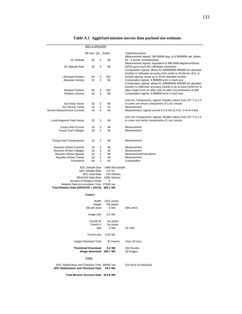
133
Table A.1 AggieSat4 mission success data payload size estimate.
ADC & DRAGON
Bit Size Qty. Subtot Type/Assumption
SC Attitude 32 3 96Measurement signed, 399.99999 deg, or 6.9999999 rad, allows for ~1 arcsec resolution/axis
SC Attitude Rate 32 3 96Measurement signed, equivalent to 999.9999 deg/second/axis (ADIS gyros have 80 LSB/deg/s resolution)
Absolute Position 64 3 192
Computation signed, allows for 999999999.999999 km absolute position to milimeter accuracy (min useful is 40 bits for LEO, to include signing, bump up to 64 bit standard number
Absolute Velocity 32 3 96 Computation signed, 9.999999 km/s in each axis
Relative Position 64 3 192
Computation signed, allows for 999999999.999999 km absolute position to millimeter accuracy (needs to be at least 41000 km to allow target to be on other side of earth (circumference at 300
Relative Velocity 32 3 96 Computation signed, 9.999999 km/s in each axis
Sun Body Vector 32 3 96Unit Vec Components, signed, handles values from 10^-7 to 1.0 to cover unit vector components of 1 arc minute
Sun Sensor Temp 16 1 16 Measurement Sensor Measurement Currents 16 4 64 Measurement, signed current 0-3.5 mA (3.XYZ, 2+4+4+4 bits
Local Magnetic Field Vector 32 3 96Unit Vec Components, signed, handles values from 10^-7 to 1.0 to cover unit vector components of 1 arc minute
Torque Rod Current 16 3 48 MeasurementTorque Rod Voltages 16 3 48 Measurement
Torque Rod Temperatures 16 3 48 Measurement
Reaction Wheel Currents 16 3 48 MeasurementReaction Wheel Voltages 16 3 48 MeasurementReaction Wheel Speeds 32 3 96 Measurement/CalculationReaction Wheel Temps 16 3 48 Measurement
Timestamp 64 1 64 Computation
ADC Sample Size 1488 bits/sampleADC Sample Rate 0.5 Hz
ADC Data Rate 744 bits/secDRAGON Data Rate 6296 bits/sec
Number of Relative Orbits 5Relative Data Accumulation Time 27000 sec
Total Relative Data (DRAGON + ADCS) 360.1 Mb
Imagery
Width 1024 pixelsHeight 768 pixels
bits per pixel 8 bits 256 colors
Image size 6.3 Mb
Thumb W 64 pixelsThumb H 64 pixels
bpp 4 bits 16 color
Thumb size 0.02 Mb
Image Download Total 30 frames 1/sec 30 secs
Thumbnail Download 0.5 Mb 330 thumbsImage download 188.7 Mb 30 images
Totals
ADC Stabilization and Checkout Time 86400 sec (24 hours of checkout)ADC Stabilization and Checkout Data 64.3 Mb
Total Mission Success Data 613.6 Mb
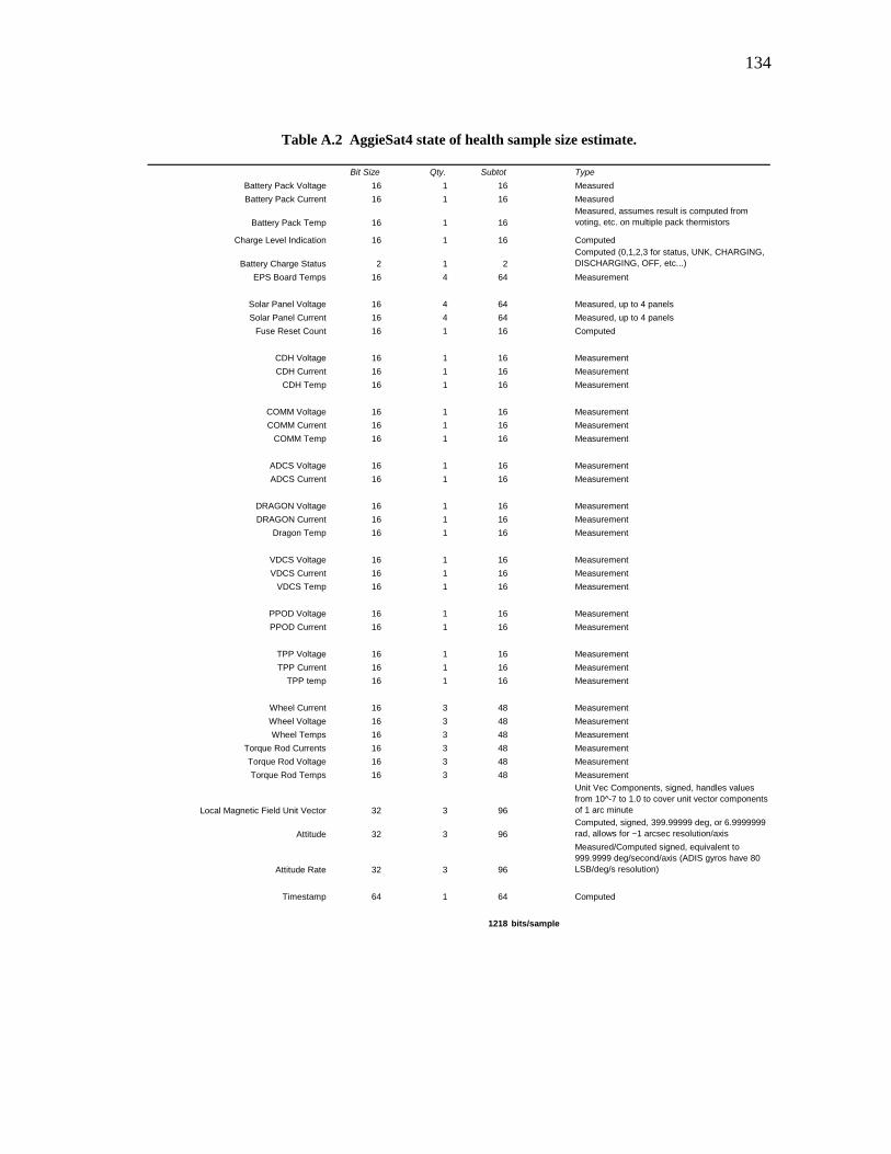
134
Table A.2 AggieSat4 state of health sample size estimate.
Bit Size Qty. Subtot TypeBattery Pack Voltage 16 1 16 MeasuredBattery Pack Current 16 1 16 Measured
Battery Pack Temp 16 1 16Measured, assumes result is computed from voting, etc. on multiple pack thermistors
Charge Level Indication 16 1 16 Computed
Battery Charge Status 2 1 2Computed (0,1,2,3 for status, UNK, CHARGING, DISCHARGING, OFF, etc...)
EPS Board Temps 16 4 64 Measurement
Solar Panel Voltage 16 4 64 Measured, up to 4 panelsSolar Panel Current 16 4 64 Measured, up to 4 panels
Fuse Reset Count 16 1 16 Computed
CDH Voltage 16 1 16 MeasurementCDH Current 16 1 16 Measurement
CDH Temp 16 1 16 Measurement
COMM Voltage 16 1 16 MeasurementCOMM Current 16 1 16 Measurement
COMM Temp 16 1 16 Measurement
ADCS Voltage 16 1 16 MeasurementADCS Current 16 1 16 Measurement
DRAGON Voltage 16 1 16 MeasurementDRAGON Current 16 1 16 Measurement
Dragon Temp 16 1 16 Measurement
VDCS Voltage 16 1 16 MeasurementVDCS Current 16 1 16 Measurement
VDCS Temp 16 1 16 Measurement
PPOD Voltage 16 1 16 MeasurementPPOD Current 16 1 16 Measurement
TPP Voltage 16 1 16 MeasurementTPP Current 16 1 16 Measurement
TPP temp 16 1 16 Measurement
Wheel Current 16 3 48 MeasurementWheel Voltage 16 3 48 MeasurementWheel Temps 16 3 48 Measurement
Torque Rod Currents 16 3 48 MeasurementTorque Rod Voltage 16 3 48 MeasurementTorque Rod Temps 16 3 48 Measurement
Local Magnetic Field Unit Vector 32 3 96
Unit Vec Components, signed, handles values from 10^-7 to 1.0 to cover unit vector components of 1 arc minute
Attitude 32 3 96Computed, signed, 399.99999 deg, or 6.9999999 rad, allows for ~1 arcsec resolution/axis
Attitude Rate 32 3 96
Measured/Computed signed, equivalent to 999.9999 deg/second/axis (ADIS gyros have 80 LSB/deg/s resolution)
Timestamp 64 1 64 Computed
1218 bits/sample
135
The state of health data is more general and assumed to be sampled at a low rate during the entire
mission and shown in A.2. The data is primarily voltages and currents from various systems, with some
temperature and attitude control data added to give a general picture of spacecraft status.
Access time is estimated by determining the average number of minutes AggieSat4 could be in
communications with a ground site at a 51.6 degree inclination space station orbit at 300 km altitude. This
is similar to the orbit that AggieSat4 is expected to be in. Over an average week, using tracking software
and a simulated orbit, this result provides about 663 seconds per day of communications time while the
spacecraft is 10 degrees above the horizon.
A single High Data Rate (HDR) ground site is assumed using a thesis radio unit, or another high rate
unit. AggieSat4 is also being designed to carry a standard amateur based system operating at 1,200 to
9,600 bps defined as a Low Data Rate (LDR) system. The LDR system can be accessed by amateur radio
operators globally. In a nominal situation it will be used to take load off the primary system. In a
contingency operation, it could be used to slowly retrieve all data.
A 50% penalty on time is applied to the primary ground site to take into account weather, anomalies,
and other general complications that could arise at a student run ground site. This is a very conservative
penalty. Two additional LDR ground sites are assumed that are available 100% of the time assuming that
on any given day AggieSat Lab could expect to find at least two amateur stations willing to send in contact
and data reports.
Table A.3 shows the download capacity results for the 9,600, 38,400, 50,000 and 150,000 bps
systems. Daily state of health data is sampled at a rate of once per minute.

136
Table A.3 AggieSat4 download capability estimates.
Time Per Day per G/S 663 secs 663 secs 663 secs 663 secs
HDR Data Rate 9600 bps 38400 bps 50000 bps 150000 bpsPass Efficiency 50% 50% 50% 50%
# G/S HDR 1 1 1 1
LDR Data Rate 1200 bps 1200 bps 1200 bps 1200 bps# G/S LDR 2 2 2 2
Raw Download Capacity 4.8 Mb/day 14.3 Mb/day 18.2 Mb/day 51.3 Mb/dayState of Health Data Sample Rate 1/60 Hz 1/60 Hz 1/60 Hz 1/60 Hz
State of Health Rate 2 Mb/day 2 Mb/day 0 Mb/day 0 Mb/dayNet Download Capacity 3.0 Mb/day 12.6 Mb/day 18.2 Mb/day 51.3 Mb/day
Mission Success Data Download Time 203 days 49 days 34 days 12 days
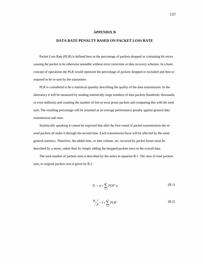
137
APPENDIX B
DATA RATE PENALTY BASED ON PACKET LOSS RATE
Packet Loss Rate (PLR) is defined here as the percentage of packets dropped or containing bit errors
causing the packet to be otherwise unusable without error correction or data recovery schemes. In a basic
concept of operations the PLR would represent the percentage of packets dropped or excluded and then to
required to be re-sent by the transmitter.
PLR is considered to be a statistical quantity describing the quality of the data transmission. In the
laboratory it will be measured by sending statistically large numbers of data packets (hundreds, thousands,
or even millions) and counting the number of lost or error prone packets and comparing this with the total
sent. The resulting percentage will be assumed as an average performance penalty against general data
transmission and rates.
Statistically speaking it cannot be expected that after the first round of packet transmissions the re-
send packets all make it through the second time. Each transmission burst will be affected by the same
general statistics. Therefore, the added time, or data volume, etc. incurred by packet losses must be
described by a series, rather than by simply adding the dropped packets once to the overall data.
The total number of packets sent is described by the series in equation B.1. The ratio of total packets
sent, to original packets sent is given by B.2.
(B.1) ∑=
+=i
n
nT pPLRpP
1
∑=
+=n
nT PLRp1
1iP (B.2)
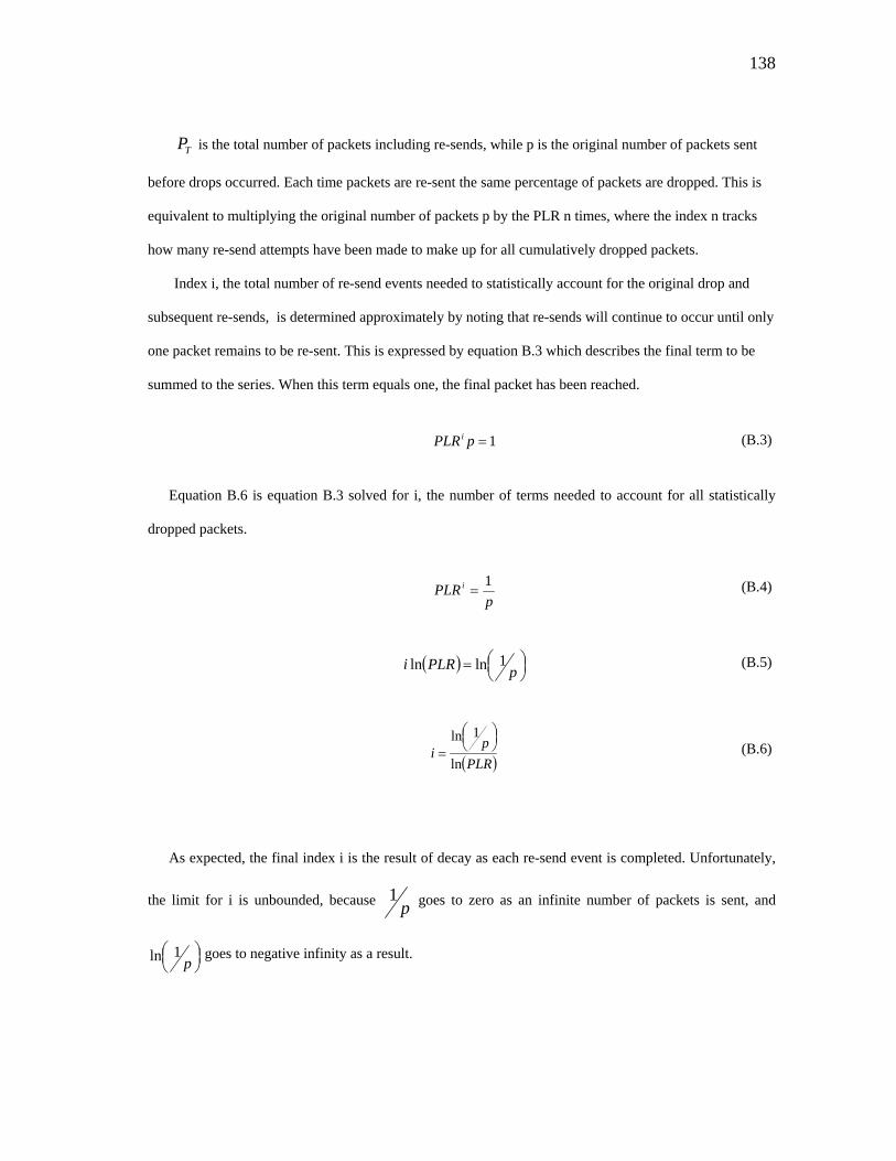
138
TP is the total number of packets including re-sends, while p is the original number of packets sent
before drops occurred. Each time packets are re-sent the same percentage of packets are dropped. This is
equivalent to multiplying the original number of packets p by the PLR n times, where the index n tracks
how many re-send attempts have been made to make up for all cumulatively dropped packets.
Index i, the total number of re-send events needed to statistically account for the original drop and
subsequent re-sends, is determined approximately by noting that re-sends will continue to occur until only
one packet remains to be re-sent. This is expressed by equation B.3 which describes the final term to be
summed to the series. When this term equals one, the final packet has been reached.
(B.3) 1=pPLRi
Equation B.6 is equation B.3 solved for i, the number of terms needed to account for all statistically
dropped packets.
p
PLRi 1= (B.4)
( ) ⎟⎠
⎜⎝
= pPLRi 1lnln ⎞⎛ (B.5)
( )PLR
pi
ln
1ln ⎟⎠
⎜⎝=
⎞⎛ (B.6)
As expected, the final index i is the result of decay as each re-send event is completed. Unfortunately,
the limit for i is unbounded, because p1 goes to zero as an infinite number of packets is sent, and
⎟⎠⎞⎜
⎝⎛
p1ln goes to negative infinity as a result.

139
By observation one can see that ratio of total packets sent, , vs. the original number of packets sent,
p, does not change dramatically as the order of magnitude of the number of packets sent is increased. This
is demonstrated by B.7, B.8, and B.9 showing /p for a PLR of 25% for 100 packets, 1,000,000 packets,
and 1,000,000,000 packets respectively.
TP
TP
( )( ) 32.3
386.1605.4
25.0ln100
1ln=
−−
==i , 32.125.011
=+= ∑=
i
n
iT
pP (B.7)
( ) 97.9
386.1816.13
25.0ln000,000,1
1ln=
−−
=⎟⎠
⎜⎝=i
⎞⎛, 333332.125.01
1=+= ∑
=
i
n
iT
pP (B.8)
( ) 95.14
386.1723.20
25.0ln000,000,000,1
1ln=
−−
=⎟⎠⎞⎜
⎝⎛
=i , 333333.125.011
=+= ∑=
i
n
iT
pP (B.9)
B.6 through B.8 show that approximately 33% more packets over the original number have to be re-
sent for a 25% PLR regardless of if the transmitter sends a hundred, million, or billion packets
successively. This percentage can be used to penalize the data budget and determine the resulting
throughput of the device based on PLR.
The data rate is effectively penalized by the extra time needed to transmit all packets for the same
given useful data payload p. Given raw transmitter data rate, R, in bits PLR second, the number of original
packets p, the total packets given by B.1 and B.6, and the bit size PLR packet, B, in bits, the real data
rate, , in bits PLR second is given by B.10 and B.11.
TP
TP
TR
RBPt T
PT= (B.10)
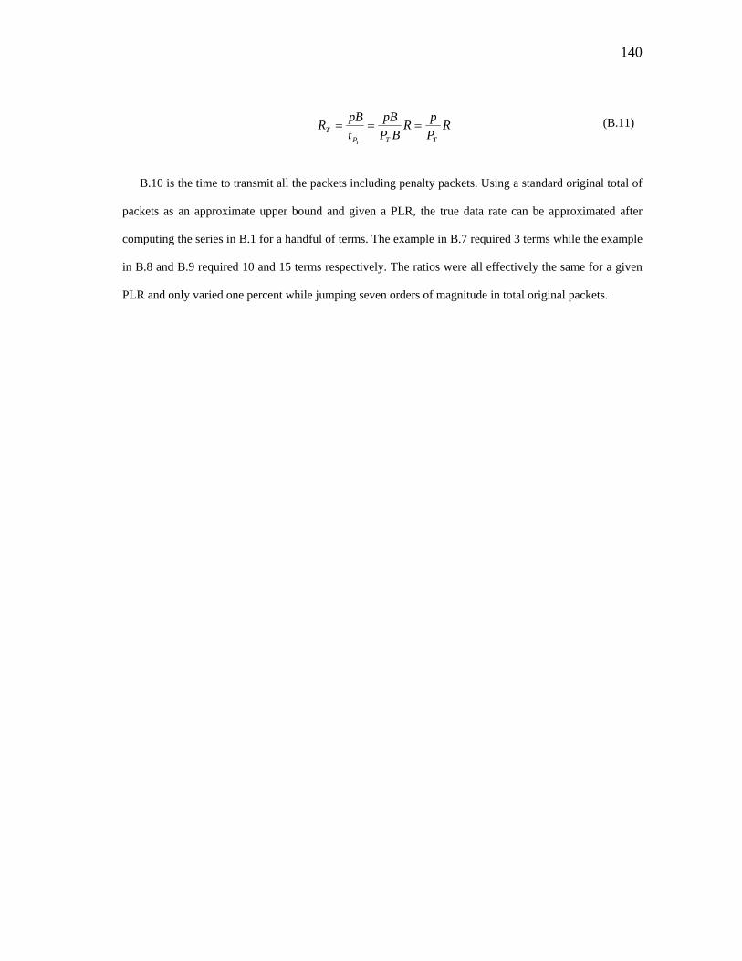
140
RP
RBPt
RTTP
TT
===ppBpB (B.11)
B.10 is the time to transmit all the packets including penalty packets. Using a standard original total of
packets as an approximate upper bound and given a PLR, the true data rate can be approximated after
computing the series in B.1 for a handful of terms. The example in B.7 required 3 terms while the example
in B.8 and B.9 required 10 and 15 terms respectively. The ratios were all effectively the same for a given
PLR and only varied one percent while jumping seven orders of magnitude in total original packets.

141
VITA
Name: John Thomas Graves
Address: 701 H.R. Bright Building, Texas A&M University, College Station, TX 77843-3141 Email Address: [email protected] Education: B.S., Aerospace Engineering, Texas A&M University, 2007 M.S., Aerospace Engineering, Texas A&M University, 2011 Professional Experience:
Graduate Lab Manager, AggieSat Lab, Texas A&M University 2008-Present Communications and Operations Lead, AggieSat2 Satellite Project 2007-2009 Project Manager, AggieSat3 Satellite Concept Development 2007
Publications and Honors:
Graduate Student Representative, Brazos Valley Shuttle Project Committee 2010-2011
Graves, J.T., et al., “The Role of Responsive Architectures in Educating Students,” 8th Responsive Space Conference, Los Angeles, CA, AIAA Paper AIAA-RS8-2010-1003, Mar. 2010, p. 5. 2010 TAMU Aerospace Department Larry Anderson Senior Achievement Award 2007 Member, Aerospace Student Undergraduate Advisory Council 2007 Distinguished Student Award, Dwight Look College of Engineering 2003