Embed Size (px)
Citation preview
DC POWER SUPPLIESDELTA ELEKTRONIKA B.V. Vissersdijk 4, 4301 ND
Zierikzee, the Netherlands
www.DeltaPowerSupplies.com
Tel. +31 111 413656
SM3000-se ries
PROD UCT MAN UALCon tents:1 - Datasheet2 - Safety Instructions3 - Descriptions4 - Operating,Trouble Shooting, Calibration5 - EC Declaration of Conformity
• SM 15 - 200 D• SM 30 - 100 D• SM 45 - 70 D• SM 70 - 45 D• SM 120 - 25 D• SM 300 - 10 D
Distribution:

SM3000 SAFETY INSTRUCTIONS
rev. February 2018 DELTA ELEKTRONIKA B.V. Page 2 - 1
2 SAFETY INSTRUCTIONS - SM3000-series
1 CautionThe following safety precautions must be observed during all phases of operation, service and repair of this equipment.Failure to comply with the safety precautions or warnings in this document violates safety standards of design,manufacture and intended use of this equipment and may impair the built-in protections. Delta Elektronika shall not beliable for user’s failure to comply with these requirements.
2 Installation CategoryThe Delta Elektronika power supplies have been evaluated to installation category II (Over voltage category II).
3 Grounding of Mains Terminals (AC Power Terminals)This product is a safety Class 1 unit. To minimize shock hazard, the unit must be connected to the AC Power Supplymains through a four conductor power cable, with the ground wire firmly connected to an electrical ground (safetyground) at the power outlet.
For units designed to be hard-wired to the mains supply , the protective earth terminal must be connected to the safetyelectrical ground before another connection is made. Any interruption of the protective ground conductor, ordisconnection of the protective earth terminal will cause a potential shock hazard that might cause personal injury.
4 Grounding of DC Power TerminalsIf the DC power terminal of a unit is specified to sink or source to a maximum of 60VDC, and either the negative orpositive DC power terminal is grounded, the voltage on the DC power terminals and sense connections can beconsidered safe.
Caution 1: If a low voltage unit has both DC power terminals floating, or if the DC terminals are in series with anexternal high AC or DC voltage, the lower DC power terminal can exceed the safe value in respect to ground asspecified in the above warning! Caution 2: Although a high voltage unit is set to a safe voltage below 60VDC, for safety it must always be considered as a high voltage unit! Wrong operation, a programming error or an external defect can result in an unsafe high DC output voltage.Caution 3: When programming a high voltage unit directly via a PC or via a network connection, either ground thenegative power output or use a safety isolated interface!For more information and schematics regards Grounding and Safety, see the special application note "Safe operation ofa power supply" on the Delta Elektronika website.
5 Danger of electrical shockTouching the contacts of the mains plug or wires directly after disconnecting from the mains can cause an electricalshock. See next paragraph "Connection to the mains supply".
6 Connection to mains supplyEither connect to the mains supply permanently or via an industrial type plug, complying with IEC 60309."Permanently connected equipment" or "Pluggable equipment type B".
7 FusesFuses must be changed by authorized Delta Elektronika service personnel only, for continued protection against risk offire.
8 AC Input RatingsDo not use an AC Supply which exceeds the AC input voltage and frequency rating of this unit. The AC input voltageand frequency rating of the Delta Elektronika power supply series are stated in the accompanying datasheet.
9 Live CircuitsOperating personnel should not remove the unit covers. No internal adjustment or component replacement is allowed by non Delta Elektronika qualified personnel. Never replace components with the power cable connected. To avoid injuries, always disconnect power, remove external voltage sources and discharge circuits before touching components.
10 Parts Substitutions & ModificationsParts substitutions and modifications are allowed by authorized Delta Elektronika service personnel only. For repairs ormodifications the unit must be returned to a Delta Elektronika service facility.
Warning: When the positive DC power terminal can exceed 60VDC in respect to the negative DC power terminal, additionalexternal measures must be taken to ensure safety isolation of the DC power terminals and sense connections.
Warning:When the negative power output of the unit can exceed 60Vdc / 42.4Vpk in respect to ground, additional externalmeasures must be taken to ensure safety isolation of the following:- power outputs and sense connections- programming/monitor/status-signals, Interlock, Master/Slave-connections, ACF/DCF-relay- interfaces with operational isolation- non-isolated interfaces.

SAFETY INSTRUCTIONS SM3000
Page 2 - 2 DELTA ELEKTRONIKA B.V. rev. February 2018
Cau tion risk of elec tri cal Shock
! Instruction manual symbol. The unit will be marked with this symbol when it isnecessary for the user to refer to the instruction manual
Pro tec tive ground con duc tor ter mi nal
o Off (sup ply)
I On (sup ply)
WEEE (Waste Electrical & Electronic Equipment)
1 Correct Disposal of this ProductApplicable in the European Union.
This marking shown on the product, its packing or its literature indicates thatit should not be disposed with other wastes at the end of its working life, butshould be collected separately to recycle it responsibly to promote thesustainable reuse of material resources.
11 Removal of (safety) covers Safety cover(s) are used to cover potentially hazardous voltages.Observe the following when removing safety cover(s):• Switch off the unit.• Disconnect the unit from the mains supply or power outlet.• Wait for 5 minutes to allow internal capacitors to discharge.• Unscrew the screws and remove the cover(s).• Always place the cover(s) back before connecting the unit to the mains supply again.
12 Environmental ConditionsThe Delta Elektronika power supplies safety approval applies to the following operating conditions:
• Indoor use• Ambient temperature : −20 to 50 °C• Maximum relative humidity : 95%, non condensing, up to 40 °C
: 75%, non condensing, up to 50 °C• Altitude : up to 2000 m• Pollution degree : 2
SM3000 DESCRIPTIONS
rev. February 2018 DELTA ELEKTRONIKA B.V. Page 3 - 1
3 DESCRIPTIONS
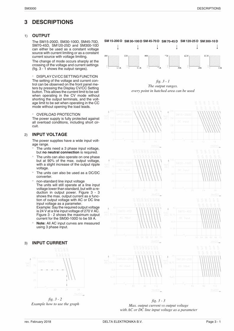
1) OUT PUTThe SM15-200D, SM30-100D, SM45-70D,SM70-45D, SM120-25D and SM300-10Dcan ei ther be used as a con stant volt agesource with cur rent lim it ing or as a con stantcur rent source with volt age lim it ing.The change of mode oc curs sharply at thecross ing of the volt age and cur rent set tings (fig. 3 - 1 shows the out put ranges).
° DIS PLAY CV/CC SETTING FUNCTIONThe set ting of the volt age and cur rent con -trol can be ob served on the front panel me -ters by press ing the Dis play CV/CC Set tingbut ton. This al lows the cur rent limit to be setwhen op er at ing in the CV mode with outshort ing the out put ter mi nals, and the volt -age limit to be set when op er at ing in the CCmode with out open ing the load leads.
° OVER LOAD PRO TEC TIONThe power sup ply is fully pro tected againstall over load con di tions, in clud ing short cir -cuit.
2) IN PUT VOLT AGEThe power sup plies have a wide in put volt -age range.° The units need a 3 phase in put volt age,
but no neu tral con nec tion is re quired.° The units can also op er ate on one phase
but at 90% of the max. out put volt age,with a slight in crease of the out put rip plevolt age.
° The units can also be used as a DC/DCcon verter.
° non-standard line in put volt ageThe units will still op er ate at a line in putvolt age lower than stan dard, but with a re -duc tion in out put power. Figure 3 - 3shows the max. out put cur rent as a func -tion of out put volt age with AC or DC linein put volt age as a pa ram e ter.Ex am ple: Say the re quired out put volt age is 24 V at a line in put volt age of 270 V AC.Figure 3 - 2 shows the max i mum out putcur rent for the SM30-100D to be 59 A.
° Note: All AC in put curves are mea suredus ing 3 phase in put.
3) IN PUT CUR RENT
SM 300-10 DSM 120-25 DSM 70-45 DSM 30-100 D SM 45-70 DSM 15-200 D
fig. 3 - 1The out put ranges.
ev ery point in hatched area can be used
fig. 3 - 2Ex am ple how to use the graph
fig. 3 - 3Max. out put cur rent vs out put volt age
with AC or DC line in put volt age as a pa ram e ter

DESCRIPTIONS SM3000
Page 3 - 2 DELTA ELEKTRONIKA B.V. rev. February 2018
The in put cir cuit has a large se ries choke to im prove the wave form. The re -sult is: a lower rms in put cur rent, less mains dis tor tion and no large peak cur -rents.The units also have an in rush cur rent lim iter and a soft start cir cuit, forsmooth switch on.° FUSES 16 A Slow blow.
4) STANDBY IN PUT POWERThe unit con sumes very lit tle power when in standby. This makes it pos si bleto leave the in put power on and use the Re mote Shut Down in put (pin 5 onprog. connector rear panel) to dis able the out put.
5) EFFICIENCYThe ef fi ciency is very high and con stant over a wide out put cur rent range(see fig. 3 - 4). High ef fi ciency also means low power loss and low heat gen -er a tion.
6) REG U LA TIONThe load reg u la tion should be mea sured di rectly on the out put ter mi nals. A few cm of ca ble can have a volt age drop of sev eral mV (at high cur rent!).
7) RIP PLE & NOISEThe out put rip ple is very low with al most no spikes.The rip ple volt age has to be mea sured di rectly on the out put ter mi nals us inga probe with very short con nec tions (to avoid pick up of mag netic fields) (seefig. 3 - 5 and fig. 3 - 6).At low tem per a tures like -20°C the rip ple in creases. By us ing high qual ityelec tro lytic ca pac i tors the in crease is rel a tively low.
8) PRO GRAMMING IN PUTSThe out put volt age and cur rent can be pro grammed by an ex ter nal an a logvolt age. This pro gram ming is very ac cu rate and lin ear, (non-lin ear ity<0.15%). The lev els are all stan dard ized on 5V. Al ways use a shielded ca -ble for pro gram ming.The in puts have a pro tec tion cir cuit formed by a se ries re sis tor and a par al lelzener (see fig. 3 - 7). The ca pac i tor lim its the speed to a safe value. Note thatthe an a log in puts (and out puts) are not float ing, but the com mon is con -nected to the neg a tive out put ter mi nal. Wrong con nec tion of Ø can cause earth loops which can trip the fuse. Af ter re mov ing the fault, the fuse will re -set (PTC-fuse). To pre vent earth loops, use iso lated pro gram ming with theISO AMP CARD in ter nal in ter face op tion P145(δ-prod uct).The pro gram ming mode (pro gram and man ual) can be se lected by means of the prog. switches which are sit u ated be low the pro gram ming con nec tor(see fig. 3- 9).
9) IEEE488 / RS232 PRO GRAMMINGFor pro gram ming use the ex ter nal in ter face PSC-488 mod ule or in ter nal in -ter face PSC-232 (both δ-prod ucts). Volt age and cur rent can eas ily be pro grammed and read back. Also the CCand OVP sta tus can be read by the com puter. Al ways use a shielded ca blefor pro gram ming.
10) MON I TORING OUT PUTSThe mon i tor out puts give a volt age 0 - 5 V pro por tional to the out put cur rentor volt age. The out put cur rent can eas ily be mea sured with out an ex ter nalshunt us ing the I-mon i tor (see fig. 3 - 8). The mon i tor out puts are buf fered byop-amp’s and pro tected by se ries re sis tors and par al lel zeners (see fig. 3 -10). The ta ble 3 - 1 shows the im ped ance lev els of the mon i tor ing out puts.For us ing Imon on a pul sat ing load, see para graph 17) of this chapter.
fig. 3 - 4Ef fi ciency vs out put cur rent, SM30-100D
DC in put , Vout = 30 V
fig. 3 - 5Mea sur ing rip ple volt age
WRONG !
fig. 3 - 6Mea sur ing rip ple volt age
RIGHT !
fig. 3 - 7Pro gram ming in puts
(in ter nal cir cuit)
V
A
Imon0-5V
Vmon0-5V
Return ofref, prog, mon.
fig. 3 - 8Ex ter nal me ters
us ing mon i tor out puts

SM3000 DESCRIPTIONS
rev. February 2018 DELTA ELEKTRONIKA B.V. Page 3 - 3
fig. 3 - 9Lo ca tion of out put ter mi nals and an a log prog. con nec tor on rear panel
fig. 3 - 10Buf fered mon i tor out puts (in ter nal cir cuit)
Out put pin Ro Io max
Vref 9 15 Ohm 10 mA
Vmon 10 20 Ohm 10 mA
Imon 2 20 Ohm 10 mA
+12V 7 500 Ohm 25 mA
Ø 1 1.2 Ohm
ta ble 3 - 1 Out puts on pro gram ming con nec tor
11) STATUS OUT PUTSThe sta tus out puts have an open out put volt age of 5 V and a short cir -cuit cur rent of 10 mA. This makes it pos si ble to drive di rectly: anopto-coupler, a TTL gate or a CMOS gate (put leak age re sis tor to Ø).
12) RE MOTE SHUT DOWNA volt age of +5V on the Re mote Shut Down in put on the pro gram mingcon nec tor will switch off the power cir cuit of the unit. In standby modethe power sup ply con sumes very lit tle power.It is also pos si ble to use a re lay con tact or a switch to shut down theunit: con nect a switch be tween Vref and Rem. Shut Down (pin 9 and 5).Note: The Re mote Shut Down will also cause the OVP-led to burn andthe OVP-sta tus will be high.
13) PRO GRAMMING SPEEDThe re sponse time is mea sured with a step wave form at the CV prog.in put. Pro gramming from a low to a high out put volt age is nearly loadin de pend ent, but pro gram ming down to a low volt age takes more timeon lighter loads. This is caused by the out put ca pac i tors, which canonly be dis charged by the load be cause the power sup ply can not sinkcur rent.When hav ing a sup ply with a fast pro gram ming op tion, the re sponse is 5 to 25 times faster (see datasheet). When us ing fast pro gram ming it is gen er ally not rec om mended to use re mote sens ing or se rial / par al lel op er a tion. Con sult fac tory for ad vice. Also the output rip ple is higher.
fig. 3 - 11 External potmeters
pin de scrip tion
1 Ø, re turn of ref er ence, prog. in puts andmon i tor out puts.
2 cur rent mon i tor out put (0 - 5V)
3 cur rent pro gram ming in put (0 - 5V)
4 CC sta tus out put, logic 1 = CC mode(5 V / 10 mA)
5 Re mote ShutDown
6 PSOL sta tus out put (op tional)
7 +12 V out put (Ri = 500 Ohm)
8 Ø, re turn of sta tus out puts, +12 V andre mote ShutDown
9 ref er ence volt age 5.1 V
10 volt age mon i tor out put (0 - 5V)
11 volt age pro gram ming in put(0 - 5V)
12 NC
13 OVP sta tus out put, logic 1 = OVP mode(5 V / 10 mA)
14 Ø, re turn of PSOL (op tional)
15 NC
fig. 3 - 12Con nec tions AN A LOG PROG. CONN.

DESCRIPTIONS SM3000
Page 3 - 4 DELTA ELEKTRONIKA B.V. rev. February 2018
14) PRO GRAMMING BAND WIDTHFor small sig nals the band width is 50 Hz, but for large sig nalsthere is a lim i ta tion in the max i mum am pli tude of the out put wave -form. The out put ca pac i tors limit the max. slew rate. Fig ure 3 - 13shows the max i mum peak to peak out put volt age swing as afunc tion of fre quency, with the load as a pa ram e ter. The higherthe load re sis tance the lower the max. am pli tude. The mea sure -ments were car ried out us ing a sine wave. The DC level of theout put is 50 % of the max. out put volt age.
15) RE COVERY TIMEFig ure 3 - 14 shows the re cov ery time for the SM30-100D at25 °C, set at 30 V out put volt age, with a 50 – 100% load step.
16) NOISE SUP PRES SION (in put / out put)The in put / out put noise sup pres sion is mea sured with a pulsegen er a tor (a) in se ries with the line in put or (b) be tween in put andcase (earth). The gen er a tor should pro duce a high en ergy pulseof about 300 V. If there is an elec tri cal con nec tion be tween theout put and the in put through the os cil lo scope, you will get a falseread ing. The sup pres sion for the SM120-25D is lower, but therel a tive dis tur bance on the out put is com pa ra ble to theSM30-100D.
17) PUL SATING LOADTo avoid over heat ing the out put ca pac i tors, the AC com po nentof the load cur rent should be lim ited (see fig. 3 - 15).One method of de creas ing the AC cur rent through the out put ca -pac i tor is by us ing a large ex ter nal elec tro lytic ca pac i tor in par al -lel with the load. Care must be taken so that the ca pac i tor incom bi na tion with the lead in duc tance will not form a se ries res o -nant cir cuit!When us ing re mote sens ing on a pul sat ing load (for in stance aDC-mo tor), use a ca pac i tor in se ries with a re sis tor over the load(see fig. 3 - 16). Like this the AC-com po nent caused by the pul -sat ing of the load is fil tered.With pul sat ing loads the I-monitor out put should not be used.
fig. 3 - 13Max. peak to peak out put volt age swing vs fre quency
fig. 3 - 14Re cov ery time SM30-100D
50 - 100 % load step, Vo=30 V
fig. 3 - 15Pul sating load current

SM3000 DESCRIPTIONS
rev. February 2018 DELTA ELEKTRONIKA B.V. Page 3 - 5
18) IN SU LA TIONFor safety the in su la tion of the sep a rat ing com po nents (trans -form ers) be tween in put and out put is tested at 3750 Vrms dur ing 1 min ute. This is tested be fore as sem bling.Warn ing! The 3750 Vrms can not be tested af ter wards on theas sem bled unit be cause the in su la tion be tween the com po -nents on the in put side to the case (like the bridge rec ti fier) isspec i fied at 2500 Vrms. Since the in su la tion out put - case is low(only 600 V DC) the in su la tion of the pri mary com po nents tocase will break down when 3750 Vrms is ap plied be tween in putand out put (2500 Vrms + 600 V DC < 3750 Vrms) (see also fig. 3- 17).Note: when test ing the in su la tion, take care to charge and dis -charge the ca pac i tors be tween in put - case and out put - caseslowly (e.g. in one sec ond). This to prevent high peak cur rents,which could de stroy the power sup ply. Make sure to have dis -charged the ca pac i tors com pletely be fore us ing it again.
19) RFI SUP PRES SIONBoth the in put and out put have RFI fil ters, re sult ing in very lowcon ducted RFI to the line and load. Due to the out put fil ter theout put volt age is very clean, hav ing al most no spikes.
20) OP ER ATING TEMPAt full power the op er at ing tem per a ture range is –20 to +50 °C.From 50 to 60 °C the out put cur rent has to be de rated lin early to75 % at 60 °C (see fig. 3 - 18). These tem per a tures hold for nor -mal use, i.e. the ven ti la tion open ings on the left and right sidemust be free.
21) THER MAL PRO TEC TIONA ther mal switch shuts down the out put in case of in suf fi cientcool ing. Af ter cool ing down the unit will start work ing again.The ther mal pro tec tion cir cuit pro tects 2 parts sep a rately in theunit: the switch ing tran sis tors on the pri mary side and the out putcir cuit.A trip ped ther mal pro tec tion can have the fol low ing ef fects:1) When the pro tec tion on the switch ing tran sis tors has trip ped, no led in di ca tor or dig i tal me ter will burn on the front panel.2) When the pro tec tion on the out put cir cuit has trip ped, theOVP led on the front panel will burn, and the OVP sta tus out putwill be high.
22) HOLD - UP TIMEThe hold - up time de pends on the load, out put volt age and linein put volt age. A lighter load, a lower out put volt age or a higherline in put volt age all re sult in a lon ger hold - up time (see fig.3 - 19).
23) TURN ON DE LAYThe out put volt age is avail able 0.5 sec af ter mains switch on.
24) IN RUSH CUR RENTThe in rush cur rent is lim ited by a 90 Ohm re sis tor, re sult ing in avery low cur rent dur ing switch on. The in put cur rent dur ingswitch on will be lower than dur ing op er a tion at full load.
25) PHASE LOSSPhase loss means that there is only one phase avail able in stead of three.The unit will con tinue to op er ate on one phase but at 90% of themax. out put volt age. Ex.: a SM30-100D on one phase 380 V can de liver 90% x 30 = 27 V @ 100 A. So if the out put volt age is notset higher than 27 V no drop in the out put volt age will be noteddur ing phase loss. How ever the out put rip ple volt age will beslightly higher when the in put is on one phase.
fig. 3 - 16Re mote sens ing on a pul sat ing load
fig. 3 - 17In su la tion test voltages
fig. 3 - 18Op er ating tem per a ture ranges
fig. 3 - 19Hold-up time vs Vout with Vin as a parameter

DESCRIPTIONS SM3000
Page 3 - 6 DELTA ELEKTRONIKA B.V. rev. February 2018
26) SERIES OP ER A TIONSe ries op er a tion is al lowed up to 600 V to tal volt age. The power sup pliescan be con nected in se ries with out spe cial pre cau tions.For eas ier con trol, Mas ter / Slave op er a tion is rec om mended (see fig. 3 -20). By us ing the Mas ter / Slave Se ries fea ture a dual track ing power sup -ply can be made with one unit as mas ter and one as slave.For se ries op er a tion in com bi na tion with Power Sink op tion, all units musthave a Power Sink built in side oth er wise no power can be ab sorbed.
27) PAR AL LEL OP ER A TIONPar al leling of the units has no lim i ta tions. The power sup plies can be con -nected in par al lel with out spe cial pre cau tions. For eas ier con trol, Mas ter /Slave op er a tion is rec om mended (see fig. 3 - 20 and fig. 3 - 21).Nor mal par al lel op er a tion of Fast Pro gram ming units can give prob lems,each com bi na tion has to be tested first, in com bi na tion with the load ! For par al lel op er a tion in com bi na tion with Power Sink op tion, only one unitcan have a Power Sink. Re fer to Power Sink man ual for de tails and re stric -tions.
28) MASTER / SLAVE OP ER A TIONThe Mas ter / Slave fea ture makes it pos si ble to use the power sup plies asbuild ing blocks to form one large unit (see fig. 3 - 21). The re sult ing com bi na tion of units be haves like one power sup ply and canbe pro grammed on the mas ter. Fig ure 3 - 23 shows a com puter con trolled M/S par al lel com bi na tion.Mixed par al lel - se ries op er a tion is also pos si ble (see fig. 3 - 22), to a max i -mum of 600 V. Here the MAS TER / SLAVE SE RIES ADAPTER (δ-prod uct)must be used. For par al lel op er a tion con nec tions can eas ily be made onthe an a log pro gram ming con nec tor.In se ries mode the mas ter con trols one slave, which in turn con trols thesec ond slave and so on. In par al lel mode the mas ter con trols all the slaves. The re sult is true cur rent or volt age shar ing in the par al lel or se ries modere spec tively.Note: Mas ter / Slave par al lel op er a tion is not rec om mended for morethan 3 units or in com bi na tion with Fast Pro gram ming op tion. Con sult fac tory for a so lu tion.
29) RE MOTE SENSINGThe volt age at the load can be kept con stant by re mote sens ing. This fea -ture is not rec om mended for nor mal use but only when the load volt age isnot al lowed to vary a few mil li volts. Al ways use a shielded ca ble for sens -ing.In or der to com pen sate for the volt age drop across the load leads, the unitwill have to sup ply a higher volt age: Uout = (volt age drop across each lead)+ (volt age across the load) (see fig. 3 - 24). The OVP reads the volt age di -rectly at the out put and the set ting must be in creased by the to tal volt agedrop across the load leads.The volt me ter is con nected to the sense leads and there fore reads the volt -age across the load and not the volt age on the out put ter mi nals.The sense leads are pro tected for ac ci den tal in ter rup tion, in which casethe out put volt age will go to a max. of 115% of the set value.Warn ing: Do not in ter rupt the mi nus lead while the S– lead is still con -nected to the load, dur ing op er a tion.For sens ing on a pul sat ing load, see pre vi ous paragraph 17).
30) OVPThe Over Volt age Pro tec tor will pro tect your cir cuit from un wanted highvolt ages. A high out put volt age could be caused by ac ci den tal in ter rup tion of leads,ac ci den tally turn ing up the volt age potmeter or a de fect in the power sup -ply. The OVP cir cuit uses a sep a rate volt age di vider con nected di rectly tothe out put ter mi nals.The OVP lim its the out put volt age to a value which can be set by the OVPpotmeter on the front panel. While do ing this, press the DIS PLAY OVPSETTING but ton to read the limit value in the left dis play. The led on thefront panel will in di cate whether the OVP has reached the limit. The OVPsta tus out put will give a logic 1 (+5 V).
Note: The Ther mal ShutDown and Re mote ShutDown will also cause theOVP-led to burn and the OVP-status will be high.
fig. 3 - 20Mas ter / Slave ser ies operation
fig. 3 - 21Mas ter / Slave parallel operation
fig. 3 - 22Mas ter / Slave mixed se ries-parallel
fig. 3 - 23The Mas ter / Slave com bi na tion can also
be pro grammed with the in ter facesPSC-488 or the PSC-232

SM3000 DESCRIPTIONS
rev. February 2018 DELTA ELEKTRONIKA B.V. Page 3 - 7
When the OVP sta tus out put is used as an in di ca tion for ac ci den tal in ter -rup tion of leads, a de fect in the power sup ply etc., it is rec om mended to setthe limit well above the work ing out put volt age to avoid ac ci den tal lim it ing. The rec om mended OVP set volt ages can be read from the fol low ing ta ble:
SM 15-200 D SM 30-100 D SM 45-70 D SM 70-45 D SM 120-25 D SM 300-10 DVovpset Vout + 2 V Vout + 3 V Vout + 5 V Vout + 5 V Vout + 10 V Vout + 25 V
Ex am ple: For a SM30-100D set at 24 V out put volt age it is rec om mended to set the OVP on 24 + 3 = 27 V.
31) PO TEN TI OM E TERS° Stan dard: - CV and CC po ten ti om eters with knobs at front panel,
OVP po ten ti om e ter with screw driver ad just ment atthe front panel.
° Op tion P001: - Screw driver ad just ment for CV, CC and OVP at thefront panel (see fig. 3 - 25).
° Op tion P002: - Screw driver ad just ment for CV, CC and OVP at therear panel (no po ten ti om eters at front panel),(see fig. 3 - 26).
32) COOLINGA low noise blower cools the unit. The speed of the fan de pends on the tem -per a ture of the in ter nal heatsink. At room tem per a ture and full load the fanwill run at a very low speed. The fan does not op er ate on no load. Normallyat 50 °C am bi ent and full load the fan will not work at full speed. Since thefan is over-rated it will still have enough ca pac ity to cool the unit when dustpar tially ob structs the fins of the heatsinks.A spe cial fea ture is that the fan blows through a tun nel where the heatsinksare sit u ated, the del i cate con trol cir cuitry is sep a rated and will not be in theair flow path (see fig. 3 - 27).Be cause the air en ters at the left and ex its at the right side it is pos si ble tostack the power sup plies, no dis tance be tween the units is re quired. Onlythe ven ti la tion open ings at the left and right side should be free.For long life the tem per a ture of the air en ter ing on the left side, should bebe low 35 °C un der nor mal con di tions. Un der ex treme conditions it shouldbe be low 50 °C.Note: The con trol cir cuit makes the fan start in a pul sat ing mode, dur ingwhich pe riod it nor mally pro duces a high pitched sound. This is nor mal.
33) DI MEN SIONS
fig. 3 - 24Re mote sens ing, volt age drop in load
leads sub tracts from max. out put
fig. 3 - 25Screw driver ad just ment at front panel
fig. 3 - 26Screw driver ad just ment at rear panel
fig. 3 - 27The fan blows through a tun nel,where the heatsinks are sit u ated

DESCRIPTIONS SM3000
Page 3 - 8 DELTA ELEKTRONIKA B.V. rev. February 2018
CIRCUIT DESCRIPTION
The 380 V AC line volt age is rec ti fied by a bridgerec ti fier and smoothed by a large elec tro lytic ca pac i -tor. The 50 Hz choke in the in put cir cuit im proves thewave form of the in put, so that no low fre quency dis -tor tion is pro duced on the line volt age.
Care fully de signed RFI fil ters pro tect the line and the load from the high fre quency in ter fer ence pro -duced in side the power sup ply.
When the unit is switched on, the elec tro lytic ca -pac i tor is charged via the re sis tor of the IN RUSHCUR RENT LIMITER cir cuit, so no large in rush cur -rent will flow. As soon as the volt age is suf fi cientlyhigh the power sup ply starts work ing and the se riesre sis tor is by passed by a re lay con tact.
The op er at ing switch ing fre quency of 200 kHz has many ad van tageslike small size, re duced weight, low rip ple and fast reg u la tion.
The rec ti fied 380 V (500 V DC) is chopped by the tran sis tors andtrans formed to a lower volt age. This 200 kHz power con verter is of thefeed for ward type. The reg u la tion is achieved by pulse width mod u la tion.
Care ful de sign, over-rating of vi tal com po nents, sev eral built-inprotections and cool op er a tion (be cause of the very high ef fi ciency)make the SM-se ries very re li able power sup plies which can be used con -tin u ously at max i mum rat ing.
fig. 3 - 28Sim pli fied func tional di a gram

SM3000 OPERATING - TROUBLE SHOOTING - CALIBRATING
rev. February 2018 DELTA ELEKTRONIKA B.V. Page 4 - 1
4 OPERATING MANUAL
1) OP ER ATING THE UNIT FOR THE FIRST TIME• Check that there is no con den sa tion on the unit. If there is, al low
some time to dry.• Set the pro gram switches on the rear panel on MAN UAL.• Check that there is a link be tween + and S+ and be tween – and
S– on the SENSE BLOCK (on rear panel)• Set OVP po ten ti om e ter (on front panel) to max i mum (fully clock -
wise), Use a screw driver to set the OVP volt age.• With high out put cur rent make sure to use low re sis tive con -
nec tions be tween the power sup ply and the load:- Mount the ca ble lugs di rectly on the tinned out put strips
fol lowed by a washer and a nut (see fig. 4 - 1). Al ways inthis or der!
- Never place ex tra wash ers be tween the lugs and the strips!- Only use nuts and wash ers sup plied with the unit.
• Switch on unit.• Turn both the CV and CC po ten ti om e ter a few turns clock wise. A
volt age should now be pres ent on the out put.• By press ing the DIS PLAY CV/CC SETTING but ton the me ters
will show the set ting of the CV and CC po ten ti om e ter.• By press ing the DIS PLAY OVP SETTING but ton the volt me ter
will show the set ting of the OVP po ten ti om e ter.• When the power sup ply is used on a fixed out put volt age it is
highly rec om mended to set the Over Volt age Pro tec tor. As setout in the fol low ing ta ble:
SM15-200D SM30-100D SM45-70D SM70-45D SM120-25D SM300-10DVout + 2 V Vout + 3 V Vout + 5 V Vout + 5 V Vout + 10 V Vout + 25 V
Ex am ple: For a SM30-100D set at 24 V out put volt age it is rec om -mended to set the OVP on 24 + 3 = 27 V.
• Check that the cool ing of the unit is not ob structed.
2) AN A LOG PRO GRAMMING• Put the ap pro pri ate switch(es) in the po si tion PRO GRAM.• Con nect the pro gram ming volt age source(s) (0 - 5 V) to the AN A -
LOG PROG. CON NEC TOR on the rear panel (see fig. 4 - 2 andfig. 4 - 3). Al ways use a shielded ca ble for pro gram ming.
• If only the volt age is pro grammed, the max i mum cur rent can stillbe set with the CC po ten ti om e ter and vice versa. If this is not de -sir able the CC or CV can be set with an ex ter nal po ten ti om e ter, in or der to have a fixed set ting.
• CAU TION: The an a log in puts are not iso lated from the out put.The Ø of the prog. in put (pin 1) is in ter nally con nected to the S–,the S– is con nected to the neg a tive out put. To pro tect the in ter nal wir ing a 650 mA self-re set ting fuse is con nected in se ries (F600on P432) (see fig. 3 - 10).
• For iso lated an a log pro gram ming the ISO AMP CARD (δ-prod -uct) is rec om mended to avoid earth loops.
• To avoid hum or noise, the pro gram ming ca ble may have to betwisted in some cases.
• To pro gram the unit by cur rent in stead of volt age, sim ply use apar al lel re sis tor as a cur rent to volt age con verter.
3) IEEE488 / RS232 PRO GRAMMING• Set both prog. switches to the po si tion pro gram.• Both CV and CC can be pro grammed and read back. The CC and
OVP sta tus can also be read by the com puter.
4) MON I TORING OUT PUTS• The 5 V level is com pat i ble with most in ter faces.• The mon i tor ing out puts can drive a me ter di rectly (see fig. 4 - 4).
fig. 4 - 1Low re sis tive ca ble con nec tion by mount ing the
ca bles di rectly on the tinned out put strips
fig. 4 - 2Pro gram ming by volt age:
left volt age -, right cur rent pro gram ming
fig. 4 - 3Pro gram ming by cur rent
left volt age -, right cur rent pro gram ming
fig. 4 - 4Re mote con trol

OPERATING - TROUBLE SHOOTING - CALIBRATING SM3000
Page 4 - 2 DELTA ELEKTRONIKA B.V. rev. February 2018
5) STATUS OUT PUTS• The sta tus out puts have a sep a rate Ø con nec tion (pin 8) to
avoid un wanted off sets in the pro gram ming. This pin is pro -tected with a 650 mA fuse (F601 on P432).
6) RE MOTE SENSING• Re move the links on the SENSE BLOCK (on rear panel) and
con nect sense leads (thin shielded mea sur ing wires) to S+and S– (see fig 4 - 5 and fig. 4 - 6).
• With re mote sens ing the volt age on the load can be kept con -stant. The volt age drop in the load leads will be com pen sated.This fea ture is not rec om mended for nor mal use, be cause itcan eas ily give prob lems.
• Max. 2 V per load lead can be com pen sated. Note that thevolt age drop in the leads de creases the max. out put volt agerat ing. In fig. 4 - 7 can be seen that on a 15 V power sup plyonly 11 V will be avail able on the load when 2x 2 V com pen sa -tion is used.
• In or der to pre vent in ter fer ence it is ad vis able to twist thesense leads. To min i mize the in duc tance in the load leadskeep the leads close to each other. The in duc tance of theloads leads could give a prob lem with pul sat ing loads. In thiscase a large elec tro lytic ca pac i tor (Cd) in se ries with a damp -ing re sis tor (Rd) both in par al lel with the load will help (see fig.4 - 6). Check that the ca pac i tor Cd in com bi na tion with the load leads and re sis tor Rd forms a well damped cir cuit.
• Since the volt me ter is in ter nally con nected to the sens ing ter -mi nals, it will au to mat i cally in di cate the volt age on the load.Note that the volt age mea sured on the load will be lower thanon the out put ter mi nals.
• The Over Volt age Pro tec tor mea sures the volt age on the out -put ter mi nals, so the OVP set ting should be in creased by theto tal volt age drop in the load leads.
7) BAT TERY CHARGER• The CV / CC reg u lated power sup plies are ideal bat tery charg -
ers. Once the out put is set at the cor rect volt age the bat terywill charge con stantly with out over charg ing. This can be use -ful for emer gency power sys tems.
• Pro tec tive mea suresUse a CIR CUIT BREAKER in se ries in or der to pro tect thepower sup ply from ac ci den tal re verse con nec tion (seefig. 4 - 8). The cir cuit breaker should have a DC volt age rat ing2x the bat tery volt age. Use the very fast type (Z), a type meant for pro tect ing semi con duc tors.The unit has a re verse di ode in par al lel with the out put, this di -ode and the wir ing can not with stand the thou sands of am -peres sup plied by a wrongly con nected bat tery.
Sug gested cir cuit break ers for pro tec tion power sup ply
Model Type num bercir cuit breaker
Brand Re marks
SM 15-200 D HTI102 B 100 GE 2 poles par al lel
SM 30-100 D HTI102 B 100 GE
SM 45-70 D HTI102 B 100 GE
SM 70-45 D S281 UC-Z 50 ABB
SM 120-25 D S281 UC-Z 25 ABB
SM 300-10 D S282 UC-Z 10 ABB 2 poles in se ries,ex tra par al leldi ode onout put needed=OP TION P023
• Re mote sens ing can not be rec om mended, be cause it eas ilycauses de fects in side the power sup ply in case of wrong con -nec tion.If you re ally need re mote sens ing, please use the cir cuit (see fig. 4 - 9). The in ter nal cir cuit can be pro tected by rel a tivelysmall anti-parallel di odes. To pro tect the anti-parallel di odes,please con nect the fuses in se ries as in di cated in fig. 3 - 9 . Aprac ti cal choice for the fuses is 250 mA, the di odes can be any nor mal 3 or 5 A type.
fig. 4 - 5Lo cal sens ing
fig. 4 - 6Re mote sens ing with shielded wires
fig. 4 - 7Re mote sens ing, volt age drop in load leads sub -
tracts from max. out put
fig. 4 - 8Charg ing bat tery with a cir cuit breaker in se ries
fig. 4 - 9Pro tect ing sense wires with di odes

SM3000 OPERATING - TROUBLE SHOOTING - CALIBRATING
rev. February 2018 DELTA ELEKTRONIKA B.V. Page 4 - 3
• Note: The SM300-10D needs an ex tra par al lel di ode on theout put, with out this di ode the in ter nal di ode will still blow. Forthis di ode 2 par al leled BYT261-PIV-400 from ST can be used. The SM300-10D with op tion P023 has an ex tra di ode built-in.
8) RE MOTE SHUT DOWN / OVER CUR RENT TRIP• The Remote ShutDown can be op er ated with +5 V or a re lay
con tact (see fig. 4 - 10).• Using the Remote ShutDown in put, an Over Cur rent Trip
could be made (see fig. 4 - 10).
9) MASTER / SLAVE SERIES OP ER A TION• For se ries op er a tion the MAS TER / SLAVE SE RIES ADAP-
TER (δ-prod uct) must be used (see fig. 4 - 11).• First, con nect out put ter mi nals and test sys tem in nor mal se -
ries op er a tion. En sure that all (out put) power con nec tions arere li able. An in ter rup tion of one of the power leads can cause afuse to blow in the unit, see ''trou ble shoot ing''.
• The volt age drop in the con nect ing leads be tween the unitsshould be kept < 10 mV.
• Sec ond, switch off all units. Con nect units as shown in fig. 4 -12. Use stan dard 15 pole (1:1) shielded ca bles.
• The max. num ber of slaves is only lim ited by the max. to tal volt -age of 600 V.
10) MASTER / SLAVE PAR AL LEL OP ER A TION• Note: Mas ter / Slave par al lel is not rec om mended for more
than 4 units, con sult fac tory for us ing more than 4 powersup plies in par al lel.
• First con nect out put ter mi nals and test sys tem in nor mal par al -lel op er a tion. En sure that all power con nec tions are re li able. An in ter rup tion of one of the (out put) power leads can cause a fuseto blow in the unit, see “trou ble shoot ing”.
• Sec ond, switch off all units. Plug in prog. connectors with thecon nec tions ac cord ing to fig. 4 - 13 (buss bar to pol ogy). Al waysuse a shielded ca ble. The shield ing must be con nected to thecase of the supply.Dis con nect the links be tween the S– and – of the slaves only.If not re moved the cur rent shar ing will not be pro por tional.Both prog. switches of the slaves should be in the po si tion PRO -GRAM.
• The pur pose of the link be tween pin 9 and 11 is to set the volt -age limit of the slaves at max i mum.
• Keep the load close to the mas ter. Keep wir ing be tween mas terand slaves short. The volt age drop be tween a unit and the bussbar should be kept < 10 mV.
• Ac ci den tal in ter rup tion of a neg a tive load lead of a unit dur ingop er a tion will cause fuse F600 to blow, see sec tion ‘trou bleshoot ing’.
• The S− and S+ could be con nected to the load if de sired, but this is not rec om mended be cause of the com plex ity.
fig. 4 - 10Left: Remote ShutDown with switch.
Right: Over Cur rent Tripfig 4 - 11
The Mas ter / Slave Ser ies Adapter,sup plied by Delta Elektronika
fig. 4 - 12Mas ter / Slave Ser ies Connection with
two MASTER / SLAVE SE RIES ADAPTERS

OPERATING - TROUBLE SHOOTING - CALIBRATING SM3000
Page 4 - 4 DELTA ELEKTRONIKA B.V. rev. February 2018
11) PAR AL LEL OP ER A TION OF FAST PRO -GRAMMING VER SIONS:• Mas ter / Slave op er a tion is not rec om mended.• Nor mal par al lel op er a tion can give prob lems, each com bi na -
tion has to be tested first in com bi na tion with the load.
12) MASTER / SLAVE MIXED SERIES / PAR AL LELOP ER A TION• For com plex com bi na tions as mixed se ries - par al lel al ways
use the MASTER / SLAVE SERIES ADAPTER (δ-prod uct).• See fig. 4 - 14 for an ex am ple of how to con nect 2 units in se -
ries in par al lel with 2 units in se ries, con trolled by 1 mas ter.• On the par al lel slave1, fully open the CV-potmeter. • Note: A Mas ter / Slave com bi na tion can al ways be pro -
grammed, also with the IEEE488 / RS232 con trol ler(PSC-488 mod ule / PSC-232 (both δ-prod ucts)).
fig. 4 - 13Mas ter / Slave par al lel connections
fig. 4 - 14Mas ter / Slave mixed se ries - par al lel con nec tions with
two MAS TER / SLAVE SE RIES ADAPT ERS

SM3000 OPERATING - TROUBLE SHOOTING - CALIBRATING
rev. February 2018 DELTA ELEKTRONIKA B.V. Page 4 - 5
OPERATING AND STORAGE CONDITIONS
1) TEM PER A TURE• The op er at ing tem per a ture range at full load is –20 to +50 °C.
But this tem per a ture range only holds when the AIR-IN TAKE andAIR-OUT LET are un ob structed and the tem per a ture of theAIR-IN TAKE is not higher than +50 °C.
• Please note: a lower tem per a ture ex tends the life of thepower sup ply.
• When the power sup ply is mounted in a cab i net please note thatthe tem per a ture of the AIR-INTAKE should be kept low and avoida short cir cuit in the air flow i.e. the hot air leav ing the AIR-OUTLET en ter ing the AIR-INTAKE again.
• The stor age tem per a ture range is –40 to +85 °C.
2) HU MID ITY• Dur ing nor mal op er a tion hu mid ity will not harm the power sup ply,
pro vided the air is not ag gres sive. The heat nor mally pro duced inthe power sup ply will keep it dry.
• Con den sa tion.Avoid con den sa tion in side the power sup ply, break-down couldbe the re sult.Con den sa tion can oc cur dur ing a pe riod the power sup ply isswitched off (or op er at ing at no load) and the am bi ent tem per a ture is in creas ing .Al ways al low the power sup ply to dry be fore switch ing it on again.
3) GAL VANIC IN DUS TRY• For us ing the power sup plies in the gal vanic in dus try it is strongly
rec om mended to take pre cau tions against an ag gres sive en vi ron -ment.
• An ag gres sive en vi ron ment with acid, salt, etc. can harm the elec -tronic com po nents. Some times even the cop per traces of thepc-boards dis solve.
• To avoid prob lems the power sup plies should be mounted in a rel -a tive clean room, or mounted in a cab i net re ceiv ing clean air withover pres sure. Or a cab i net with a heat exchanger.
MAINTENANCE
1) GEN ERAL• The SM-series power sup plies nor mally need no main te nance or
cal i bra tion. Only care must be taken that the cool ing of the unit isnot ob structed.
2) COOLING FAN• The built up of dust on the im pel ler of the fan and the heat sink fins
de pends on the en vi ron ment. Since the fan has over-capacitydust will not pres ent a prob lem very quickly.
• The in ter nal con struc tion of the power sup ply is such that no dustwill reach the sen si tive con trol cir cuitry, only the heat sinks in atun nel will be cooled by forced air (see fig. 4 - 15).
• The ther mal pro tec tion will shut down the out put in case of over -heat ing, so no dam age will be done to the power sup ply.
• It is ad vis able to in spect the fan and the heat sinks reg u larly.
fig. 4 - 15The fan blows through an in ter nal tun nel,
where the heatsinks are sit u ated

OPERATING - TROUBLE SHOOTING - CALIBRATING SM3000
Page 4 - 6 DELTA ELEKTRONIKA B.V. rev. February 2018
TROUBLE SHOOTING
1) GEN ERAL• In case you need as sis tance for re pair ing a unit, please con tact
our en gi neers us ing the ad dress "[email protected]".• In case you want us to re pair the unit, please first fill out the
RMA-form be fore send ing the unit to us. Add ing a de tailed faultde scrip tion will help us to re pair the unit as soon as pos si ble.On our website www.DeltaPowerSupplies.com the RMA-formcan be found un der 'Sup port'.
2) NO OUT PUT (nor mal op er a tion)• Check in put fuses.• Check po si tion of prog. switches at the rear panel, they should be
on MAN UAL.• Check the con nec tions on the SENSE BLOCK (at rear panel),
there should be a link be tween + and S+ and be tween – and S–.• Set OVP po ten ti om e ter (at front panel) at max i mum (fully clock
wise).• Switch on unit.• Turn both the CV and CC po ten ti om e ter a few turns clock-wise. A
volt age should be pres ent on the out put.
3) PRO GRAMMING DOES NOT WORK OK• Check po si tion of prog. switches at rear panel.• The unit works OK in man ual con trol, but in pro gram ming
mode the out put volt age / cur rent has a large er ror.Prob a bly the fuse in se ries with Ø (pin 1) of prog. connector trip -ped, the fuse (F600 = 650 mA) is a self-resetting type (seefig. 4 - 16).
• To check the fuse (F600) mea sure the volt age be tween Ø and themi nus out put, dur ing the fault con di tion. The volt age should onlybe a few mV, a high volt age means that an un wanted cur rent isflow ing through pin 1 of the prog. con nec tor.Please check why cur rent is flow ing through pin 1 (see also nextpara graph 4) and fig. 4 - 17).
4) PRO GRAMMING OFF SETS• Un wanted off sets in the pro gram ming can be caused by
earth loops.Fig ure 4 - 17 shows a typ i cal earthing prob lem. In case the loadhas a con nec tion to earth and the pro gram ming source as well,prob lems could oc cur. Im proper choice of the earthing point of the load can give a volt age drop of ∆V1. Con necting the mi nus or zero to a sep a rate earth con nec tion can give a volt age drop of ∆V2. Be -cause the in ter nal wires of the pro gram ming in put are thin, thevolt age drops ∆V1 and ∆V2 will be across the in ter nal wir ing aswell. Re sulting in a er ror volt age in se ries with the pro gram mingvolt age.
• The best so lu tion for this is us ing a float ing pro gram ming sourcewith the help of the ISO AMP CARD (δ-prod uct) or a float ing load.
5) STATUS OUTPUTS FAIL• Check fuse F601 in se ries with Ø (pin 8) (see fig. 4 - 16). To check
the fuse (F601) mea sure the re sis tance be tween Ø and the mi nusout put, an open cir cuit means a blown fuse. F601 = 650 mA.
6) MASTER / SLAVE PAR AL LEL PROB LEMS• Ac ci den tal in ter rup tion of a mi nus lead of a unit dur ing op er a tion
will cause fuse F600 to blow (see fig. 4 - 16). To check the fuse(F600) mea sure the re sis tance be tween Ø (pin 1 of prog. conn.)and the mi nus out put, the fuse is a self re set ting type.F600 = 650 mA
• Check link be tween pin 9 and 11 on the prog. con nec tor of theslaves
• Cur rent shar ing is not ok. Prob a bly the links be tween S– and – ofthe slaves are not re moved.
fig. 4 - 16Lo ca tion of pro gram ming fuses on P432
P432 is sit u ated on the rear panel
fig. 4 - 17Un wanted pro gram ming off sets

SM3000 OPERATING - TROUBLE SHOOTING - CALIBRATING
rev. February 2018 DELTA ELEKTRONIKA B.V. Page 4 - 7
7) OUT PUT VOLT AGE IS HIGHER THAN SET VALUE• Check con nec tions on SENSE BLOCK (on rear panel), For nor -
mal op er a tion there should be a link be tween + and S+ and be -tween – and S– (see also fig. 4 - 18). When re mote sens ing isused, check the wires of the sens ing.
8) OVP LED on.• Check OVP set ting.• Over heating also causes the OVP led to be on, cool ing down will
re set the ther mal pro tec tion.• You are us ing Re mote Sensing.
Even a short volt age pulse >3V be tween – and S – causes theOVP cir cuit to limit the out put volt age.
• Re mote ShutDown volt age is ap plied to the prog. con nec tor.
9) NO LEDS on.• Over heating can be the cause, cool ing down will re set the ther mal
pro tec tion.• Check in put power and in put fuses (on rear panel)• Check fuses F400 and F401 on P430, a blown fuse can be
caused by a de fec tive rec ti fier bridge D400 or D401. Note: Thefuses are of a spe cial 500 V type.
• The aux il iary power sup ply (board P430) is de fect. Do not try to re -pair P430 (ex cept for D400, D401, F400 and F401), but sendP430 for re pair or ask for re place ment.
10) CHECK POINTS IN CASE OF A SE RI OUS FAIL URE
• Check out put di odes.De fec tive di odes give a short.
SM 15-200 D Check di odes D300 - D315SM 30-100 D Check di odes D300 - D309SM 70-45 D Check di odes D300 - D303 on P457SM 120-25 D Check di odes D300 - D303 on P458Re place de fec tive parts.
• Fuse F200 and / or F201 on P428 are blown.
Prob a bly there is a de fect on one of the two boards P433.First check out put di odes, see above.
WARNING: Do not re place F200 or F201until the unit is re paired.Re placing fuse F200 and F201 while P433 is still de fect will causeR104 till R109 to blow, this will dam age the board P428.
Note: Do not try to re pair P433, but send the sub unit with 2x P433for re pair or ask for re place ment.Pref er a bly con sult fac tory when you dis cover a de fect in P433.
Check fuses on rear panel
No Out put
No LED on
Re place P430,see 8)
One or moreLEDs on
Check fuse F200,F201 on P428
Pro ceed withsec tion: FuseF200, F201 isblown see 9).
Pro ceed withsec tion: Checkout put di odes
BlownO.K.
The unit is notover heated
fig. 4 - 18For nor mal op er a tion links should be con nected
be tween S+ and + and be tween S– and –

OPERATING - TROUBLE SHOOTING - CALIBRATING SM3000
Page 4 - 8 DELTA ELEKTRONIKA B.V. rev. February 2018
CALIBRATION
1) GEN ERAL• The power sup plies are fac tory cal i brated
and nor mally need no fur ther cal i bra tion.
2) METER CAL I BRA TION• DIG I TAL ME TERS
The zero in di ca tion can be cal i brated withR712 and R716, the full scale in di ca tion canbe cal i brated with R706 and R708 on P388(see fig. 4 - 19).
3) SPE CIAL CAL I BRA TIONS• The fol low ing cal i bra tions must be done by
qual i fied per son nel only. Wrong cal i bra tioncauses mal func tion. These cal i bra tions areonly needed af ter spe cial re pairs. Warn ing !Dam age caused by wrong cal i bra tion is notwar ranted.
• CAL I BRATING MAX. CUR RENT RANGEor CAL I BRATING CC MON I TOR FULLSCALE.The max. out put cur rent can be cal i bratedwith R686. R686 is lo cated on P432 (seefig. 4 - 20).Pro gram CC in put with ex actly 5.00 V. Setout put volt age to a low value, en sur ing thepower sup ply is in CC mode. Mea sure theout put cur rent with an ac cu rate shunt. Cal i -brate the cur rent with R686 ex actly on therated max. cur rent.Warn ing! Wrong cal i bra tion can dam agethe unit.
• CAL I BRATING THE CC MON I TOR OFF -SET.With R652 on P384 the off set of the CC mon -i tor volt age can be cal i brated (see fig. 4 - 21). The unit has to be un loaded, the out put volt -age set on a low value. Mea sure the off setvolt age of the CC mon i tor on the prog. con -nec tor. Cal i brate the off set on a neg a tivevalue be tween –10 mV and zero mV.Warn ing! wrong cal i bra tion can dam age the unit.
4) SPARE PARTS
• When or der ing spare parts please state:Model, Se rial num ber, Com po nent num berand Com po nent de scrip tion.
Ex am ple:- Model .............SM 30-100 D- Se rial no. ........Sn821701900017- BSU no...........Bs816802900036- Com po nent.....D300- Description. ....BYV52-PI-200
fig. 4 - 19 Me ter cal i bra tion with 25-turn potmeters on P388
fig. 4 - 20 Cal i brating max. cur rent on P432
fig. 4 - 21 On P384, CC mon i tor can be cal i brated

rev. February 2018 DELTA ELEKTRONIKA B.V. Page 5 - 1
SM3000 EC DECLARATION
We
Delta ElektronikaVissersdijk 44301 ND ZIERIKZEEThe Neth er lands
De clare un der sole re spon si bil ity that the fol low ing Power Sup plies:
SM 15-200 DSM 30-100 DSM 45-70 DSM 70-45 DSM 120-25 DSM 300-10 D
Meet the in tent of Di rec tives 2014/30/EC for Elec tro mag netic Com pat i bil ity andDi rec tives 2014/35/EC re gard ing Elec tri cal Safety. (Low Volt age Di rec tive)Com pli ance was dem on strated to the fol low ing spec i fi ca tion as listed in the of fi cial Jour nalof the Eu ro pean Com mu ni ties:
EN 61000-6-3 Ge neric Emis sions: (res i den tial, light in dus trial)
EN 55022 Ra di ated and con ducted, Class BEN 61000-3-3 Volt age fluc tu a tion and flicker
EN 61000-6-1 Ge neric Im mu nity: (res i den tial, light in dus trial)
EN 61000-6-2 Ge neric Im mu nity: (in dus trial en vi ron ment)
EN 61000-4-2 Elec tro static Dis chargeEN 61000-4-3 Ra di ated elec tro mag netic fieldsEN 61000-4-4 Elec tri cal Fast Tran sients / BurstsEN 61000-4-5 Surge on DC out putEN 61000-4-5 Surge on line in putEN 61000-4-6 RF com mon mode, con ductedEN 61000-4-11 Volt age vari a tions and dips
EN 60950 Safety of IT equip ment
EN 61010 Safety of elec tri cal equip ment for mea sure ment, con trol and lab o ra tory use
EC Dec la ra tion of Con for mity - SM3000-series
Man ag ing di rec torZierikzee, Feb ru ary 2018
DC POWER SUPPLIESDELTA ELEKTRONIKA B.V. Vissersdijk 4, 4301 ND
Zierikzee, the Netherlands
www.DeltaPowerSupplies.com
Tel. +31 111 413656