Embed Size (px)
Citation preview

J Electr Eng Technol.2018; 13(?): 1921-718 http://doi.org/10.???/JEET.2018.13.2.1921
1921Copyright The Korean Institute of Electrical Engineers
This is an Open-Access article distributed under the terms of the Creative Commons Attribution Non-Commercial License (http://creativecommons.org/ licenses/by-nc/3.0/) which permits unrestricted non-commercial use, distribution, and reproduction in any medium, provided the original work is properly cited.
Sliding Mode Control Based DTC of Sensorless Parallel-Connected Two Five-Phase PMSM Drive System
Tounsi Kamel*, Djahbar Abdelkader*, Barkat Said**, M. Al-Hitmi*** and Atif Iqbal†
Abstract – This paper presents a sensorless direct torque control (DTC) combined with sliding mode approach (SM) and space vector modulation (SVM) to achieve mainly a high performance and reduce torque and flux ripples of a parallel-connected two five-phase permanent magnet synchronous machine (PMSM) drive system. In order to increase the proposed drive robustness and decrease its complexity and cost, the rotor speeds, rotor positions, fluxes as well as torques are estimated by using a sliding mode observer (SMO) scheme. The effectiveness of the proposed sliding mode observer in conjunction with the sliding mode control based DTC is confirmed through the application of different load torques for wide speed range operation. Comparison between sliding mode control and proportional integral (PI) control based DTC of the proposed two-motor drive is provided. The obtained speeds, torques and fluxes responses follow their references; even in low and reverse speed operations, load torques changes, and machines parameters variations. Simulation results confirm also that, the ripples of the torques and fluxes are reduced more than 3.33% and 16.66 %, respectively, and the speed overshoots and speed drops are reduced about 99.85% and 92.24%, respectively.
Keywords: Five-phase permanent magnet synchronous machine; Direct torque control; Sliding mode control; Sliding mode observer
1. Introduction
Recently, the use of high power semiconductor devices has opened the door to new scopes in electrical drives. The five-phase PMSM may be is one of the newest ideas in this field. This has led to an increasing interest in multiphase (greater than three phases) drives. Here and now, in some industrial applications such as high power ship propulsion, electric aircraft, electric traction, the use of this kind of drives is very suitable due to their tangible benefits over the conventional three-phase drives. Their advantages include reducing the amplitude of torque and current pulsations, increasing the frequency of torque pulsations, reducing the stator current per phase without increasing the stator voltage per phase, lowering the DC link current harmonics, higher reliability, and fault tolerance capability [1-3].
Different control algorithms of the PMSM were proposed in the literature [4-8]. Among all these control methods, the DTC is one of the effective control techniques adopted to control torque and flux linkage. The DTC is considered particularly interesting being less parameters dependency; making the system more robust, fast dynamic response,
and a pretty simple control [9]. Furthermore, the DTC avoids the need to the internal current loops, coordinate transformations, and the modulator block; hence the delay caused by current regulator is eliminated. It directly selects voltage vectors according to the error between the reference and the estimated values of the torque and flux [10]. However, the main disadvantages of using hysteresis controllers are: difficulty to control flux and torque at low speed, unfixed switching frequency which changes with rotor speed and load torque [9], a high sampling frequency needed for digital implementation of hysteresis controllers, and high torque ripple responsible for noises and vibrations generation [11]. In order to handle the above-mentioned problems, several researchers have proposed many approaches to overcome the drawbacks of the basic DTC. A space vector modulation was implemented to replace the switching table and provide a constant inverter switching frequency [12-13]. The resulting DTC-SVM approach substitutes the hysteresis controllers by two PI controllers to generate the direct and quadrature voltage components in synchronous frame. This scheme reduces torque and flux ripples as stated in [14-15].
However, some factors such as neglected dynamics, parameter variations, friction forces, and load disturbances are the main disturbances and uncertainties that can affect the effective functioning of the drive system. So, it will be very difficult to limit these disturbances effectively if linear control methods like PI controllers are adopted [11, 16]. To overcome this problems, especially to enhance stability and robustness of the DTC scheme other advanced
† Corresponding Author: Dept. of Electrical Engineering, Qatar University, Qatar. ([email protected])
* Dept. of Electrical Engineering, Chlef University, Algeria.([email protected], [email protected])
** Dept. of Electrical Engineering, M’sila University, Algeria. ([email protected])
*** Dept. of Electrical Engineering, Qatar University, Qatar ([email protected])
Received: January 20, 2016; Accepted: November 4, 2017
ISSN(Print) 1975-0102 ISSN(Online) 2093-7423
Proofreading
Sliding Mode Control Based DTC of Sensorless Parallel-Connected Two Five-Phase PMSM Drive System
1922 J Electr Eng Technol.2018; 13(2): 1921-718
methods have been proposed [4, 15, 17-18]. These approaches include among others the sliding mode control. The SMC is a nonlinear control method known to have robust control characteristics under restricted disturbance conditions or when there are limited internal parameter modeling errors as well as when there are some nonlinear behaviors [10, 11, 20-21]. The robustness of the SMC is guaranteed usually by using a switching control law. Unfortunately, this switching strategy often leads to a chattering phenomenon. In order to mitigate the chattering phenomenon, a common method is to use the smooth function instead of the switching function [16, 22-23].
The parallel/series-connected multi-machine systems fed by a single supply become strongly suggested due to the following benefits: low cost drive, compactness, and lightness [24-25]. In the series-connected system, both beginnings and ending of each phase should be brought out to the terminal box of each multiphase machine, these results in system complexity and poor efficiency due to higher losses. As a suitable alternative, the parallel connection of multiphase machines has been suggested in [26]. In multiphase machine there are more than direct and quadrature current components. Actually, to control the torque and flux of any multiphase only direct and quadrature current components are used, the remaining components can be used to control the others machines which are fed by a single multi-leg inverter [27].
It is well established that the PMSM can be efficiently controlled only if the position of the rotor is accurately known. Generally, the rotor position is obtained using some sensors types such as an optical encoder or resolver connected to the rotor shaft [24, 28]. However, the use of these sensors will increase the cost and reduce the reliability of the drive, and may suffer from some restrictions such as temperature, humidity, and vibration. These problems can be solved by using the well-known sensorless control technology. Various methods of sensorless control have been proposed by several researchers [29-31]. These estimation techniques are based mainly on the measurement of the machine currents and voltages. However, few applications deal with sensorless control of multiphase machines such as, model reference system [32], Kalman filtering technique [33] and sliding mode observer of five-phase PMSM [34,35]. Unlike the other approaches, the SMO is more attractive due to its robustness against the system parameters variations, disturbances, and noises [36]. This type of observer is based on the system model and the use of a high frequency switch to force the estimated variables trajectories to remain on the sliding surface. A low pass filter is used to reduce the chattering caused by sign function. However, the adding of this filter generates phase delay. Thus, the resulting SMO cannot improve the control in high performance applications [37]. Indeed, there were several researches that proposed another SMO as alternative to remove low-pass filter and phase delay in
[34, 36]. In conventional sensorless DTC scheme, one possible
solution is to combine a current observer and flux estimator [8, 12, 29] to perform the sensorless task, which increases the system complexity and reduce the accuracy of the estimation. To solve this problem, a SMO is proposed in this paper to improve the sensorless control of each five-phase PMSM by using its flux model in the stationary reference frame. Similar to the SMC, in the SMO algorithm the conventional switch function is replaced also by a smooth function to reduce the chattering phenomenon.
Most of the previous works on parallel connected multi-phase was done on induction motor drive systems using indirect vector control based on PI controllers to control each motor independently [24, 26]. However, the uncertainties and parameters disturbances can strongly influence the decoupling between the two motor [4]. In addition, all of these research works used sensors to measure the rotors positions, which increase the cost and the complexity of the system.
The purpose of this paper is to study a sensorless DTC sliding mode control scheme (DTC-SMC) equipped with a sliding mode observer for parallel connected two five-phase PMSMs fed by a single five-leg inverter. To obtain the desired characteristics, the SMC is implemented for speeds, fluxes and electromagnetic torques control and the SMO is used for sensorless operation purposes. The developed control scheme combines the features of the robust control and the robust estimation to enhance the performances of the proposed two-machine drive. So, the proposed nonlinear sensorless DTC-SMC based on SMO is attended to minimize the torque and stator flux ripples which are the main disadvantage of the classical DTC.
The performance of the estimation and control scheme is tested with challenging variations of the load torque and speed reference. The obtained results prove that the two machines are totally decoupled under large speeds and loads variations, although they are connected in parallel and supplied by a single inverter. In addition to that, a comparison between SMC, the traditional PI based DTC, and conventional DTC for sensorless operation is also provided.
2. Drive System Description and Modeling The two-machine drive system under consideration is
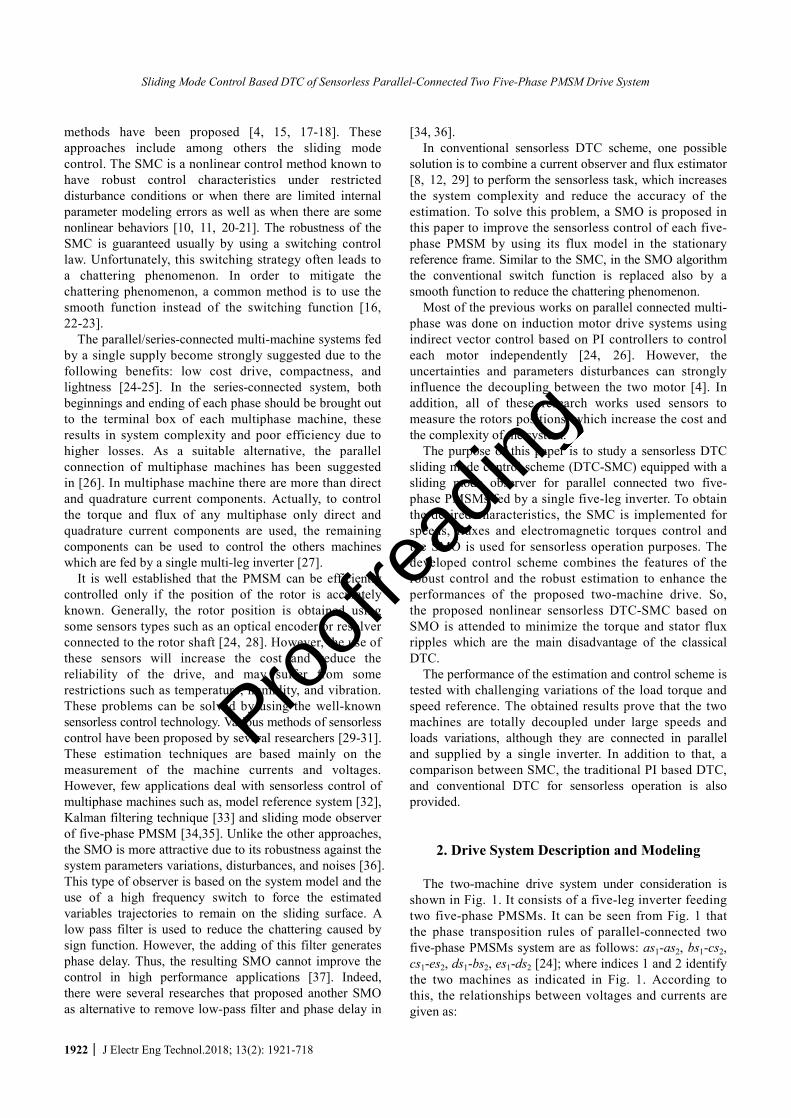
shown in Fig. 1. It consists of a five-leg inverter feeding two five-phase PMSMs. It can be seen from Fig. 1 that the phase transposition rules of parallel-connected two five-phase PMSMs system are as follows: as1-as2, bs1-cs2, cs1-es2, ds1-bs2, es1-ds2 [24]; where indices 1 and 2 identify the two machines as indicated in Fig. 1. According to this, the relationships between voltages and currents are given as:
Proofreading
Tounsi Kamel, Djahbar Abdelkader, Barkat Said, M. Al-Hitmi and Atif Iqbal
http://www.jeet.or.kr 1923
Stator of PMSM1
Stator of PMSM2
Fig. 1. A parallel connected five-phase two-motor drive
1 2 1 2
1 2 1 2
1 2 1 2
1 2 1 2
1 2 1
;
inv inva aas as as asinv invb bbs cs bs csinv inv
abcde c cs es abcde c cs esinv inv
ds bs ds bsd dinv inves ds ese e
v iv v i iv iv v i i
v v v v i i i iv v i iv iv v i iv i
é ù é ù= +é ùê ú ê úê ú= +ê ú ê úê úê ú ê ú= = = = = +ê úê ú ê ú= +ê úê ú ê úê ú= +ê ú ê úë û
ë û ë û2ds
é ùê úê úê úê úê úë û
(1)
where , , , ,inv inv inv inv inva b c d ev v v v v and , , , ,inv inv inv inv inv
a b c d ei i i i i are the inverter voltages and currents, 1,2 1,2 1,2, , ,as bs csv v v 1,2 ,dsv
1,2esv and 1,2 1,2 1,2 1,2 1,2, , , ,as bs cs ds esi i i i i are the voltages and currents of the two machines.
The main five dimensional systems can be decomposed into five dimensional uncoupled subsystems (α-β-x-y-0). The correlation between the original phase variables and the new (α-β -x- y-0) variables is given by xyo abcdef Cfab = , where C is the following transformation matrix [24]:
1 cos(2 5) cos(4 5) cos(6 5) cos(8 5)0 sin(2 5) sin(4 5) sin(6 5) sin(8 5)
2[ ] 1 cos(6 5) cos(2 5) cos(8 5) cos(4 5)5 0 sin(6 5) sin(2 5) sin(8 5) sin(4 5)
1/ 2 1/ 2 1/ 2 1/ 2 1/ 2
C
p p p pp p p pp p p pp p p p
é ùê úê ú
= ê úê úê úë û
(2) By applying the transformation matrix (2) on equation
(1), the voltage and current components of the five-phase inverter become:
1 2
1 2
1 2
1 2
0
1 2
1 2
1 2
1
0
[ ] ,
0
[ ]
invs xsinvs ys
inv invx abcde xs sinv
ys syinv
invs xsinvs ys
inv invx abcde xs sinv
ysyinv
v v vv v vv C v v v
v vvv
i i ii i ii C i i i
i iii
a ab b
a
b
a ab b
a
é ù =é ùê úê ú= -ê úê úê ú = = =ê úê ú
=ê úê úê úê ú ë ûê úë û
é ù +ê ú+ê ú
ê ú = = +ê ú
+ê úê úê úë û
20
sb
é ùê úê úê úê úê úë û
(3)
where Lsj, Llsj are the inductances in the rotating frame and rsj is the stator resistance; fjF is the magnet flux; jw and
jq are electrical speed and rotor position, respectively. Where 0, , , ,inv inv inv inv inv
x yv v v v va b and 0, , , ,inv inv inv inv invx yi i i i ia b
are the inverter voltages and currents in the α, β, x, y, 0 axes, respectively. , , ,sj sj xsj ysjv v v va b and , , ,sj sj xsj ysji i i ia b (j=1,2) are the stator voltages and currents in the α, β, x, y axes, respectively.
The model of each five-phase PMSM (j=1, 2) is presented in a rotating α-β -x-y frame is given as:
( sin( ) ) /
( cos( ) ) /
( ) /
( ) /
sjsj sj j fj j sj sj
sjsj sj j fj j sj sj
xsjsj xsj xsj lsj
ysjsj ysj ysj lsj
dir i v L
dtdi
r i v Ldt
dir i v L
dtdi
r i v Ldt
aa a
bb b
w q
w q
= - + F +
= - - F +
= - +
= - +
(4)
The stator flux linkage components of each machine are
given by:
sjsj sj sj
sjsj sj sj
xsjsj xsj xsj
ysjsj xsj xsj
dr i v
dtd
r i vdt
dr i v
dtd
r i vdt
aa a
bb b
F= - +
F=- +
F= - +
F= - +
(5)
where , , ,sj sj xsj ysja bF F F F are the flux linkage in the αβxy frame.
The torques equations for the first and the second machines are given by:
11
22
5( )
25
( )2
em s s s s
em xs ys ys xs
pT i i
pT i i
a b b a= F -F
= F -F (6)
where p1, p2 are the pole pairs.
The proposed sensorless DTC-SMC of the parallel-connected two five-phase permanent magnet synchronous machines is presented in Fig. 2, where the two main parts SMC and SMO are considered. The SMO has been proved being strong robust and accurate with a fast convergence and having a good estimation performance over full speed rang [34, 37]. The SMO is designed to estimate the rotor position, speed, torque and flux of each machine by using voltages and currents measurements. The actual speed, estimated speed and load torques are the inputs of the
Proofreading

Sliding Mode Control Based DTC of Sensorless Parallel-Connected Two Five-Phase PMSM Drive System
1924 J Electr Eng Technol.2018; 13(2): 1921-718
speeds SMCs to determine the torques references. The estimated flux and torque are processed in DTC-SMCs to obtain as outputs the α-β-x-y axes reference voltages components. These reference voltages become the input signals to the SVM blocks. The SVM transmits the gating signals to the five-leg inverter to drive the two five-phase PMSMs connected in parallel.
3. Sliding Mode Control The design of a sliding mode controller requires mainly
two stages. The first stage is choosing an appropriate sliding surface. The second stage is designing a control law, which will drive the state variables to the sliding surface and will keep them there.
3.1 Sliding surfaces choice
In order to prescribe the desired dynamic characteristics
of the controlled system, the following general form of sliding surface can be adopted [38].
1( ) ( ) ( )rdS x e xdt
l -= + (7)
with ( ) refe x x x= - , l is a positive coefficient, and r is the relative degree, which is the number of times required to differentiate the surface before the input appears explicitly. 3.2 Controller design
In order to drive the state variables to the sliding surface,
the following control law is adopted:
eqc dicu u u= + (8) The equivalent control eqcu is capable to keep the state
variables on the switching surface, once they reach it, and to achieve the desired performance under nominal model. It is derived as the solution of the following equation:
( ) ( ) 0S x S x= =& (9)
Switching Signals Slection
SVM
SVM
SMC
abcdeto
αβxySMO1
PMSM1
PMSM2
abcdeto
αβxy
SMC
SMO2
DTC-
SMC2
DTC-
SMC1
SVM of five-phase parallel-connected two-motor drive
Fig. 2. Sensorless DTC-SMC of a parallel-connected two five-phase PMSMs drive system
Proofreading

Tounsi Kamel, Djahbar Abdelkader, Barkat Said, M. Al-Hitmi and Atif Iqbal
http://www.jeet.or.kr 1925
The discontinuous control dicu is needed to assure the convergence of the system states to sliding surfaces in nite time, and it should be designed to eliminate the effect of any unpredictable perturbation. The discontinuous control input can be determined with the help of the following Lyapunov function candidate:
21 ( )2
V S x= (10)
The control stability is ensured under the following two
conditions: - The Lyapunov function V is positive definite. - The derivative of the Lyapunov function should be negative ( ) ( ) 0 ( )TV S x S x S= < "&& .
The so-called reaching stability condition . .
( 0)V S S= < is fulfilled using the following discontinuous control:
( ( ))dicu k sign S x= (11)
where k is a control gain.
In order to reduce the chattering phenomenon, a saturation function instead of the switching one can be used. The saturation function is expressed as follows:
sgn( ( )) ( )
( ( )) ( ) ( )
S x if S xsat S x S x if S x
d
dd
ì >ï= í<ïî
(12)
with d is the boundary layer width.
4. Sliding Mode Control of the Five-Phase Two-
Machine Drive
4.1 Speed SMC design The sliding mode speed controller for each five-phase
PMSM is designed by selecting the suitable sliding surfaces ( )jS W . Since the relative degree is one, the following sliding surfaces are adopted:
( ) , 1, 2j refj jS jW = W -W = (13)
By taking the derivative of the sliding surfaces given by
(13) with respect to time and using the machines motion equations, it yields:
1
2
1 1 1 11 1 1
1 1 1
2 2 2 22 2 2
2 2 2
5( )
25
( )2
f lref qs
f lref ys
p T fS iJ J J
p T fS iJ J J
F WW = W - + +
F WW = W - + +
& &
& & (14)
where , andj j ljJ f T are the moment of inertia, damping
coefficient, and load torque of each machine, respectively. The currents controls 1qsi and 2ysi are defined by:
1 1 1
2 2 2
qs qseqc qsdic
ys yseqc ysdic
i i ii i i
= += + (15)
where:
1 1 1 1 11 1 1 1
1 1
2 2 2 2 22 2 2 2
2 2
, and ( ( ))52
, and ( ( ))52
ref lqseqc qsdic
f
ref lyseqc ysdic
f
J T fi i k sat S
p
J T fi i k sat S
p
W
W
W + + W= - = W
F
W + + W= - = W
F
&
&
1kW and 2kW are positive constants. The reference torques are computed as:
11 1 1
22 2 2
52
52
emref f qs
emref f ys
pT i
pT i
= F
= F (16)
4.2 Stability analysis
During the convergence mode, the condition ( ) ( ) ( ) 0 ( ( ))TV x S x S x S x= < "&& must be verified. Indeed,
by replacing (15) into (14), one gets:
1
2
11 1 1
1
22 2 2
2
5( ) ( ) 0
25
( ) ( ) 02
fT
fT
pV S k sat
Jp
V S k satJ
W
W
FW = - W <
FW = - W <
&
& (17)
From (17) the derivatives are negative, which means that
the stability condition is ensured.
4.3 Torques and fluxes SMCs design The DTC-SMC is designed to generate the stator voltage
command from the torque and flux errors to track the electromagnetic torque and flux by controlling the input voltage of the motor.
The electromagnetic torque and stator flux linkage squared are given by:
2 2 2
5( )
2j
emj sj sj sj sj
sj sj sj
pT i ia b b a
a b
= F -F
F = F +F (18)
The control objectives are to track the desired torques
and fluxes trajectories. So, the sliding surfaces can be
Proofreading

Sliding Mode Control Based DTC of Sensorless Parallel-Connected Two Five-Phase PMSM Drive System
1926 J Electr Eng Technol.2018; 13(2): 1921-718
calculated as follows:
*
*2 2
( )( )
emj emj emj
sjsj sj
T T S TS
Sé ù- é ùê ú= = ê úFF +Fê ú ë ûë û
(19)
Using (4) and (5), the time derivative of (19) can be
rewritten as:
1 2 2 1
1 1 2 2
2 12 1 1
21 2
5 5( ) ( sin( )) ( cos( ))2 2
( ) 2 2
5 5( ) ( )
2 2
2 2
j jemj sj h s j fj j h s sj h s j fj j h s
sj sj h s h s sj h sj h s
j h sj j h sh s h s h s
sj sjh s
h s h s
p pS T r i r iS r i r i
p pi i v
L Lv
w q w q- -é ùé ù - F F + F Fê úê ú = ê úê úF - F - Fë û ê úë û
- F -é ùF- - é ùê ú
+ ê úê úë ûê ú- F - Fë û
&
&
(20)
with h1=α, x and h2=β, y. So, the equation (20) can be expressed in the following
matrix form:
S F DU= +& (21)
with:
( )( )
emj
sj
S TS
S
é ù= ê ú
Fê úë û
&&
&
1 2 2 1
1 1 2 2
5 5( sin( )) ( cos( ))
2 22 2
j jsj h s j fj j h s sj h s j fj j h s
sj h s h s sj h s h s
p pr i r iF
r i r i
w q w q- -é ù
- F F + F Fê ú= ê ú- F - Fê úë û
2 12 1
1 2
1
2
5 5( ) ( )
2 22 2
j jh s h sh s h s
sj sj
h s h s
h s
h s
p pi i
D L L
vU
v
- -é ùF F- -ê ú= ê ú
ê ú- F - Fë ûé ù= ê úë û
So, it is possible to choose the control laws for stator
voltages as follows:
1 1 1
2 2 2
h s h seqc h sdic
h s h seqc h sdic
v v vv v v
= += + (22)
where
1 1 1
2 2
FF
h seqc
h seqc
vD
v-é ù é ù= -ê ú ê úë ûë û
11
2
k sat(T )k sat( )
Temj emjh sdic
h sdic j sj
vD
v-
F
é ùé ù = - ê úê ú Fë û ë û
with kTemj, k sjF are positive gains.
4.4 Stability analysis During the convergence mode, the condition ( )V x =& ( ) ( ) 0 ( ( ))TS x S x S x< "& must be verified. Indeed, by
replacing (22) into (21), one gets:
k (T )
( ) 0sat( )j
sj
Tem emjT
sj
satV S S
k F
é ù= - <ê úFê úë û
& (23)
From (23) it is obvious that the system is globally stable,
S and S& will be forced to zero in a definite period, which also means that the torque and flux of the five-phase PMSM will follow their reference values.
5. SVM Technique Based DTC-SMC Hysteresis controllers used in the conventional DTC
generate a variable switching frequency, causing electro-magnetic torque ripples [2, 15]. In order to overcome this problem, the adopted solution consists in replacing the hysteresis controllers and the switching table by two SMC controllers and a space vector modulator.
The five-phase inverter has totally thirty-two space voltage vectors, thirty non-zero voltage vectors and two zero voltage vectors. Each voltage vector can be mapped by (24) onto the α-β subspace and x-y subspace as shown in
9v 16v 25v26v
29v24v
20v13v
10v
22v
5v11v 18v
21v27v
1v23v
2v
15v
4v30v 8v
6v
7v
3v 19v
17v
28v12v
14v
v b
v a
0v
31v
6v 16v 22v19v
30v18v
24v14v
3v
25v12v
7v 17v28v
23v
4v29v
1v
15v
8v27v 2v
9v
13v
5v 21v
20v
26v10v
11v
xv
yv
0v
31v
Fig. 3. Space vectors of a five-phase inverter in two 2-D
subspaces
Proofreading

Tounsi Kamel, Djahbar Abdelkader, Barkat Said, M. Al-Hitmi and Atif Iqbal
http://www.jeet.or.kr 1927
Fig. 3. [27]:
2 3 4
2 4 6 8
2 ( )52 ( )5
inv inv inv j inv j inv j inv ja b c d e
inv inv inv j inv j inv j inv jxy a b c d e
v v v e v e v e v e
v v v e v e v e v e
a a a aab
a a a a
= + + + +
= + + + + (24)
where 2
5pa = .
From Fig. 3 the space vectors are divided into three groups in accordance with their magnitudes: small, medium and large space vector groups. The magnitudes are identified with indices s, m, and l, and are given as:
( ) 4 5cos 2 5s dcV vp= , 2 5m dcV v= , and ( ) 4 5cos 5l dcV vp= , respectively [27, 39]. It can be
observed from Fig. 3 that medium length space vectors of the α-β plane are mapped into medium length vectors in the x-y plane, and large vectors of the α-β plane are mapped into small vectors in the x-y plane, and vice-versa.
The reference voltage can be obtained by averaging a certain number of active space vectors for adequate time intervals, without saturating the VSI. Four active space vectors are required to reconstruct the reference voltage vector [27, 40].
6. Sliding Mode Observer Based Speed Estimator for Parallel-Connected Two-Motor Drive
Normally, speed observers used for three-phase machines
can be easily extended to multi-phase multi-machine drives. For each machine the speed estimator requires only stator voltages and currents components. In the five-phase PMSM control case, α, β, x, y currents and voltages are measured.
In this section, a sliding mode observer based on flux model is presented to estimate directly the flux and speed as well as the electromagnetic torque by using stator voltages and currents as inputs. Using the flux model of the five-phase PMSM and based on the sliding-mode variable structure theory, the proposed sliding mode observer for each five-phase PMSM is designed as:
ˆ
ˆˆ( / ) cos( ) ( )
ˆˆˆ( / ) sin( ) ( )
ˆˆ( / ) ( )
ˆˆ( / ) ( )
ˆ 52
sjsj sj sj sj sj fj j sj
sjsj sj sj sj sj fj j sj
xsjxsj sj lsj xsj xsj
ysjysj sj lsj ysj ysj
j j
dv r L r ksat
dtd
v r L r ksatdt
dv r L ksat
dtd
v r L ksatdt
d pdt J
aa a a
bb b b
q
q
F= - F + F + F
F= - F - F + F
F= - F + F
F= - F + F
W= ˆ ˆˆ ˆ( )[ cos( ) sin( )]fj
sj j sj jj sjL b aq qF
F -F
1 11ˆ ( ) ( )lj sj sj
j j
f T k sat k satJ J a b- W- + F + F
ˆˆj
jddtq
= W (25)
with ˆ
sj sj sja a aF = F -F , ˆsj sj sjb b bF = F -F , xsjF =
ˆxsj xsjF -F and ˆ
sj ysj ysjbF = F -F are the sliding surfaces, and k, k1 are the observer gains. ˆ ˆ ˆ ˆ
sj sj xsj ysja bF F F F are the estimated stator flux linkage components. ˆ
jW and ˆjq are
the estimated mechanical speed and rotor position, respectively.
The actual flux components can be obtained from:
ˆcos( )ˆsin( )
sj sj sj fj j
sj sj sj fj j
xsj lsj xsj
ysj lsj xsj
L i
L iL iL i
a a
b b
q
q
F = +F
F = +FF =F =
(26)
6.1 Stability analysis
The estimation errors dynamics are:
( / )
ˆ( / ) (cos( ) cos( )) ( )
( / )
ˆ( / ) (sin( ) sin( )) ( )
( / ) ( )
( / ) ( )
sjsj sj sj
sj sj fj j j sj
sjsj sj sj
sj sj fj j j sj
xsjsj lsj xsj xsj
ysjsj lsj ysj ysj
j
dr L
dtr L ksat
dr L
dtr L ksat
dr L ksat
dtd
r L ksatdt
dd
aa
a
bb
b
q q
q q
F= - F
+ F - - F
F= - F
+ F - - F
F= - F - F
F= - F - F
W
1 1
5 ˆˆ( ) [ cos( ) cos( ))2
ˆˆ( sin( ) sin( ))]1ˆ ( ) ( )
j fjsj j sj j
j sj
sj j sj j
lj sj sjj j
pt J L
f T k sat k satJ J
b b
a a
a b
q q
q q
F= F -F
- F -F
- W- - F - F
jj
ddtq
= W (27)
with ˆ
j j jW = W -W and ˆj j jq q q= - .
In order to demonstrate the stability of the proposed sliding mode observer, the following Lyapunov function candidate is adopted:
2 2 2 2 2 21 ( )2 sj sj xsj ysj j jV a b q= F +F +F +F +W + (28)
Its time derivative is:
Proofreading
Sliding Mode Control Based DTC of Sensorless Parallel-Connected Two Five-Phase PMSM Drive System
1928 J Electr Eng Technol.2018; 13(2): 1921-718
. ..
... .
.2
2
2
ˆ( / ) ( / ) (cos( ) cos( ))
( ) ( / )ˆ( / ) (sin( ) sin( )) ( )
( / )
sj sjsj sj
xsj ysjxsj ysj
sj sj sj sj sj sj fj j j
sj sj sj sj sj
sj sj sj fj j j sj sj
sj lsj xsj
V
V r L r L
ksat r L
r L ksat
r L
a ba b
a a
a a b
b b b
q q
q q
q q
= F F +F F
+F F +F F +W W+
= - F +F F -
-F F - F
+F F - -F F
- F -2
( )
( / ) ( )5 ˆˆ( )[ cos( ) cos( ))2
1ˆˆ( sin( ) sin( ))]
xsj xsj
sj lsj ysj ysj ysj
j fjsj j sj j
j sj
sj j sj j j j lj j
ksat
r L ksatpJ L
f TJ J
b b
a a
q q
q q
F F
- F -F FF
F -F
- F -F W - W - W
1 1( ) ( ) 0j sj j sj j jk sat k sata b q-W F -W F +W < (29) To force the observer to converge to its sliding surfaces,
the observer gains must be chosen to fulfill the following conditions:
max
1 max max
2
2
s fjj
sj
fjj
j sj
rk p
L
k pJ L
F> W
F> F W
(30)
7. Simulation Results
In order to verify the feasibility of the proposed control
scheme for the two-machine drive system presented in Fig. 2, a series of simulations is performed using two identical five-phase PMSM. The parameters of each machine are listed in Table 1. The performance of the SMC controller is compared with that of the PI controller and conventional DTC. The tuning parameters for the SMC and SMO are also given in Table 2. The switching frequency of the five-phase inverter is set at 10 kHz.
Simulations results are obtained for both controllers under the same conditions (same DC-link voltage, same switching frequency). Different operation modes of the proposed multiphase drive have been presented such as no
load starting up, load torque application, speed direction reversing, low-speed operation and robustness test. In every test, speeds, estimation errors, torques, stator fluxes and their circular trajectories will be presented.
Case 1: Two motors operating in the same direction
Fig. 4 shows the operation of the two-machine drive
system for many different speeds references with no load at starting up phase. At steady state condition, the two machines are loaded simultaneously or not by their nominal loads. At the beginning, the first machine is running at 60 rad/s; at t=0.25 s, it is accelerated to 100 rad/s, after that, its direction of rotation is reversed to -80 rad/s at t=0.5 s and then to -40 at t=0.75 s. For the second machine the speed reference is set at 40 rad/s, 80 rad/s, -100 rad/s, and -60 rad/s at t=0 s, 0.25 s, 0.5 s, 0.75 s, respectively. From Figs. 4(a), it can be seen that using DTC-SMC approach the two machines reach their speed references rapidly at starting phase without overshoots compared to the DTC-PI and conventional DTC approach. The load variations have not any tangible effects on the speeds responses contrary to DTC-PI and conventional DTC where drops and rises are observed during the same variations instants. Furthermore, faster dynamic and better reference tracking during the speed reversing operation are observed when the proposed DTC-SMC is used.
The estimations errors are illustrated in Figs. 4(b). From these figures, the speed estimation errors converge toward zero in steady state, which means that the SMO shows good speed estimation, and the load does not have a significant effect on the tracking performance. Indeed, the maximum speeds estimation errors in DTC-SMC scheme are less than 0.08% (Fig. 4(b) (DTC-SMC)), but for the DTC-PI and conventional DTC schemes, they are less than 0.11%, Fig. 4(b) (DTC-PI) with noticeable ripples in case of conventional DTC.
The electromagnetic torques, generated by the two machines during the simulated speed step response, are shown in Figs. 4(c). Compared to DTC-PI and conventional DTC controllers, the proposed DTC-SMC controller shows a significant improvement in torque response time as well as in the overshoots and undershoots magnitudes. It can also be seen that DTC-SMC has a better dynamic and faster torque response during the startup and direction reversing states. In addition, it can be seen that the torque ripple in conventional DTC is greater than DTC-PI and DTC-CMC.
Figs. 4(d) show the stator flux magnitudes using the proposed DTC-SMC, DTC-PI, and conventional DTC, respectively. In case of DTC-SMC controller, it can be observed that the stator flux ripples in steady state are less than those obtained by DTC-PI and conventional DTC.
Figs. 4(e) describe the stator flux trajectories in αβ and xy plane. The αβ trajectories are almost circular but the xy trajectories are closed to zero. In these figures, it can be
Table 1. Five-phase PMSM parameters
pj Lsj fjF
Jj rsj fj srefjF
2 5.6mH 0.2444 Wb 0.00174 kg.m2 1.4 W 0 0.3 Wb
Table 2. SMC and SMO parameters
Speed controller
Torque controller
Flux controller SMC
4jkW = 9000Temjk = 9000jGF = SMO k=99000, k1=300
Proofreading

Tounsi Kamel, Djahbar Abdelkader, Barkat Said, M. Al-Hitmi and Atif Iqbal
http://www.jeet.or.kr 1929
seen again that DTC-SMC controller offers the better and fast response without overshoot and less ripple compared to the DTC-PI and conventional DTC.
Case 2: Two motors operating in the opposite directions
The effect of the speed rotation reversion of one
machine on the other machine performance is investigated in Fig. 5. In the stating phase, the first machine is rotating
at +100 rad/s; the other is running at the opposite speed. After that
Ω1 is kept at standstill, while Ω2 is reversed from -100 to +100 rad/s at t=0.4 s, and it is returned to zero at t=0.6 s. At the subsequent test, the speed Ω2 is held at zero, while Ω1 is set at -100 rad/s at 0.7s.
Compared with DTC-PI and conventional DTC, the DTC-SMC shows again no overshoots and no significant influence of the load application. Furthermore the results
a
b
c
d
e
a
b
c
d
e
0 0.2 0.4 0.6 0.8 1-100
-50
0
50
100
Time (s)
Spee
ds (r
ad/s
)
W1W1estW1refW2W2estW2ref
0.01 0.02 0.03 0.040
20
40
60
0 0.2 0.4 0.6 0.8 1-0.1
-0.05
0
0.05
0.1
Time (s)
Spee
ds e
rror
(rad
/s)
estimation error1estimation error2
0 0.2 0.4 0.6 0.8 1-40
-20
0
20
40
Time (s)
Torq
ues
(N.m
)
Tem1Tem2
0.05 0.1 0.15
-1
0
1
0 0.2 0.4 0.6 0.8 1
-0.1
-0.05
0
0.05
Time (s)
Spee
ds e
rror
(rad
/s)
estimation error1estimation error2
0 0.2 0.4 0.6 0.8 1-40
-20
0
20
40
Time (s)
Torq
ues
(N.m
)
Tem1Tem2
0.05 0.1 0.15
-1
0
1
0 0.2 0.4 0.6 0.8 10
0.1
0.2
0.3
0.4
Time (s)
Fs1
,2 (W
b)
Fs1Fs2
-0.4 -0.2 0 0.2 0.4-0.4
-0.2
0
0.2
0.4
Fa (Wb)
Fb (W
b)
Fab1
Fab2
Fxy 1,2
0 0.2 0.4 0.6 0.8 10
0.1
0.2
0.3
0.4
Time (s)
Fs1
,2 (W
b)
Fs1Fs2
-0.4 -0.2 0 0.2 0.4-0.4
-0.2
0
0.2
0.4
Fa (Wb)
Fb (W
b)
Fab1
Fab2
Fxy 1,2
0 0.2 0.4 0.6 0.8 1-0.1
-0.05
0
0.05
0.1
Time(s)
Spee
ds e
rror
(rad
/s)
estimation error1estimation error2
-0.4 -0.2 0 0.2 0.4-0.4
-0.2
0
0.2
0.4
Fa (Wb)
Fb (
Wb)
Fab1
Fab2
21,Fxy
0 0.2 0.4 0.6 0.8 10
0.1
0.2
0.3
0.4
Time(s)
Fs F
s1,2
(Wb)
(Wb)
Fs1Fs2
0 0.2 0.4 0.6 0.8 1-150
-100
-50
0
50
100
Time(s)
Spee
ds (r
ad/s
)
W1West1W ref1W2West2W ref2
0 0.02 0.040
204060
0 0.2 0.4 0.6 0.8 1-40
-20
0
20
40
Time(s)To
rque
s (N
.m)
0.05 0.1 0.15
-202
Tem1Tem2
0 0.2 0.4 0.6 0.8 1-200
-100
0
100
200
Time (s)
Spee
ds (r
ad/s
)
0 0.02 0.040
20
40
60
W1West1W ref1W2West2W ref2
a
b
c
d
e
(DTC-SMC) (DTC-PI) ( DTC-switching up-table)
Fig. 4. Dynamic responses of parallel-connected two five-phase PMSMs system controlled by SMC, PI based DTC, and conventional DTC and operating at different reference speeds values: (a) Reference, actual and estimated speeds, (b) Speed estimation errors, (c) Electromagnetic torques, (d) Stator fluxes magnitudes, (e) Stator fluxes trajectories
Proofreading

Sliding Mode Control Based DTC of Sensorless Parallel-Connected Two Five-Phase PMSM Drive System
1930 J Electr Eng Technol.2018; 13(2): 1921-718
illustrated in Fig. 5 show once more that the control of the two machines is completely decoupled. Indeed, the speed of one machine and its electromagnetic torque remain completely undisturbed during the reversion of the other machine, indicating a complete decoupling of the control.
So, there is hardly any evidence of torque disturbance of one machine during the reversal of the other one. As shown from Figs. 5(a), the starting and reversing transients of one machine do not have any tangible consequence on the operation of the second machine. The decoupled control is
a
b
c
d
e
a
b
c
d
e
0 0.2 0.4 0.6 0.8 1-200
-100
0
100
200
Time (s)
Spee
ds (r
ad/s
)
W1West1W ref1W2West2W ref2
0 0.2 0.4 0.6 0.8 1-40
-20
0
20
40
Time (s)
Torq
ues
(N.m
)
Tem1Tem2
0 0.2 0.4 0.6 0.8 1-100
-50
0
50
100
Time (s)
Spee
ds (r
ad/s
)
W1West1W ref1W2West2W ref2
0 0.2 0.4 0.6 0.8 1-0.1
-0.05
0
0.05
0.1
Time (s)
Spee
ds e
rror
(rad
/s)
estimation error1estimation error2
0 0.2 0.4 0.6 0.8 1
-20
-10
0
10
20
Time (s)
Torq
ues
(N.m
)
Tem1Tem2
0 0.2 0.4 0.6 0.8 10
0.1
0.2
0.3
0.4
Time (s)
Fs1
,2 (W
b)
F
s1F
s2
-0.4 -0.2 0 0.2 0.4-0.4
-0.2
0
0.2
0.4
Fa (Wb)
Fb (W
b)
Fab1
Fab2
Fxy 1,2
0 0.2 0.4 0.6 0.8 10
0.1
0.2
0.3
0.4
Time (s)
Fs1
,2 (W
b)
Fs1Fs2
-0.4 -0.2 0 0.2 0.4-0.4
-0.2
0
0.2
0.4
Fa (Wb)
Fb (W
b)
Fab1
Fab2
Fxy 1,2
0 0.2 0.4 0.6 0.8 1
-100
0
100
200
Time (s)
Spee
ds (r
ad/s
)
W1West1W ref1W2West2W ref2
0 0.2 0.4 0.6 0.8 1-0.1
-0.05
0
0.05
0.1
Time(s)
Spee
ds e
rror
(rad
/s)
estimation error1
estimation error2
0 0.2 0.4 0.6 0.8 1-40
-20
0
20
40
Time(s)
Torq
ues
(N.m
)
Tem1
Tem2
0 0.2 0.4 0.6 0.8 10
0.1
0.2
0.3
0.4
Time(s)
Fs1
2(Wb)
Fs1Fs2
-0.4 -0.2 0 0.2 0.4-0.4
-0.2
0
0.2
0.4
Fa(Wb)
Fb (W
b)
Fab1
Fab2
2Fxy 1,
a
b
c
d
e
0 0.2 0.4 0.6 0.8 1-0.15
-0.1
-0.05
0
0.05
0.1
Time (s)
Spee
ds e
rror
(rad
/s)
estimation error1
estimation error2
(DTC-SMC) (DTC-PI) ( DTC-switching up-table)
Fig. 5. Dynamic responses of parallel-connected two five-phase PMSMs system controlled by SMC, PI based DTC, and conventional DTC: when the two motors are operating in the opposite directions: (a) Reference, actual and estimated speeds, (b) Speed estimation errors, (c) Electromagnetic torques, (d) Stator fluxes magnitudes, (e) Stator fluxes trajectories
Proofreading

Tounsi Kamel, Djahbar Abdelkader, Barkat Said, M. Al-Hitmi and Atif Iqbal
http://www.jeet.or.kr 1931
preserved and the characteristics of both machines are unaffected.
Case 3: Operation at different loading conditions
Fig. 6 shows the performance of the two-machine drive
controlled by DTC-SMC, DTC-PI, and conventional DTC
controllers under load torques variations condition. The reference of the first speed is set at 100 rad/s, while the speed reference of the second machine is set at 50 rad/s. A set of load torques from 5 Nm to 2.5 Nm are applied on the two machines shafts in different times. It is clear from Fig. 6 that when one machine is either loaded or unloaded, the
a
b
c
d
e
a
b
c
d
e
0 0.2 0.4 0.6 0.8 10
20
40
60
80
100
Time (s)
Spee
ds (r
ad/s
)
W 1 W est1 W ref1 W 2 W est2 W ref2
0 0.2 0.4 0.6 0.8 1-0.04
-0.02
0
0.02
0.04
0.06
Time (s)
Spe
eds
erro
e (r
ad/s
)
estimation error1estimation error2
0 0.2 0.4 0.6 0.8 1
0
5
10
15
20
Time (s)
Torq
ues
(N.m
)
Tem1Tem2
0 0.2 0.4 0.6 0.8 10
20
40
60
80
100
120
Time (s)
Spee
ds (r
ad/s
)
W 1 W est1 W ref1 W 2 W est2 W ref2
0 0.2 0.4 0.6 0.8 1-0.05
0
0.05
0.1
0.15
Time (s)
Spee
ds e
rror
(rad
/s)
estimation error1estimation error2
0 0.2 0.4 0.6 0.8 1-10
0
10
20
30
40
Time (s)
Torq
ues
(N.m
)
Tem1Tem2
0 0.2 0.4 0.6 0.8 10
0.1
0.2
0.3
0.4
Time (s)
Fs1
,2 (W
b)
F
s1F
s2
-0.4 -0.2 0 0.2 0.4-0.4
-0.2
0
0.2
0.4
Fa (Wb)
Fb (W
b)
Fab1
Fab2
Fxy 1,2
0 0.2 0.4 0.6 0.8 10
0.1
0.2
0.3
0.4
Time (s)
Fs1
,2 (W
b)
Fs1Fs2
-0.4 -0.2 0 0.2 0.4-0.4
-0.2
0
0.2
0.4
Fa(Wb)
Fb (W
b)
Fab1
Fab2
Fxy 1,2
0 0.2 0.4 0.6 0.8 1-0.05
0
0.05
0.1
0.15
Time(s)
Spee
ds e
rror
(rad
/s)
estimation error1estimation error2
0 0.2 0.4 0.6 0.8 1-10
0
10
20
30
Time(s)
Torq
ues
(N.m
)
Tem1Tem2
0 0.2 0.4 0.6 0.8 10
0.1
0.2
0.3
0.4
Time (s)
Fs1
2 (Wb)
Fs1Fs2
-0.4 -0.2 0 0.2 0.4-0.4
-0.2
0
0.2
0.4
Fa (Wb)
Fb (W
b)
Fxy1,2
Fab1
Fab2
0 0.2 0.4 0.6 0.8 10
20
40
60
80
100
120
Time(s)
Spee
ds(r
ad/s
)
W 1 W est1 W ref1 W 2 W est2 W ref2
a
b
c
d
e
(DTC-SMC) (DTC-PI) (DTC-switching up-table) Fig. 6. Dynamic responses of parallel-connected two five-phase PMSMs system controlled by SMC, PI based DTC ,and
conventional DTC and operating at different loading conditions: (a) Reference, actual and estimated speeds, (b) Speed estimation errors, (c) Electromagnetic torques, (d) Stator fluxes magnitudes, (e) Stator fluxes trajectories
Proofreading

Sliding Mode Control Based DTC of Sensorless Parallel-Connected Two Five-Phase PMSM Drive System
1932 J Electr Eng Technol.2018; 13(2): 1921-718
second machine performance is unaffected; which proves once again that both motors connected in parallel are totally decoupled. In case of sliding mode control, no variation whatsoever can be observed in the speeds responses of the both machines during these transients. It is
worth noticing that there is no impact on the speed and electromagnetic torque of one machine when the speed or the load of the other machine in parallel-connected system changes. Thus, through proper phase transformation rules, the decoupled control of two five-phase PMSMs connected
a
b
c
d
e
a
b
c
d
e
0 0.2 0.4 0.6 0.8 1-10
-5
0
5
10
Time (s)
Spe
eds
(rad
/s)
W
1
West1
Wref1
W2
West2
Wref2
0 0.2 0.4 0.6 0.8 1-0.1
-0.05
0
0.05
0.1
Time (s)
Spe
eds
erro
r (r
ad/s
)
estimation error
1estimation error
2
0 0.2 0.4 0.6 0.8 1-10
-5
0
5
10
Time (s)
Spe
eds
(rad
/s)
W
1
West1
Wref1
W2
West2
Wref2
0 0.2 0.4 0.6 0.8 1-0.03
-0.02
-0.01
0
0.01
Time (s)
Spee
ds e
rror
(rad
/s)
estimation error
1estimation error
2
0 0.2 0.4 0.6 0.8 1-5
0
5
10
Time (s)
Torq
ues
(N.m
)
T
em1T
em2
0 0.2 0.4 0.6 0.8 1-20
-10
0
10
20
Time (s)
Torq
ues
(N.m
)
T
em1T
em2
0 0.2 0.4 0.6 0.8 10
0.1
0.2
0.3
0.4
Time (s)
Fs1
,2 (W
b)
Fs1
Fs2
-0.4 -0.2 0 0.2 0.4-0.4
-0.2
0
0.2
0.4
Fa (Wb)
Fb (W
b)
Fab1
Fab2
Fxy 1,2
0 0.2 0.4 0.6 0.8 10
0.1
0.2
0.3
0.4
Time (s)
Fs1
,2 (W
b)
Fs1
Fs2
-0.4 -0.2 0 0.2 0.4-0.4
-0.2
0
0.2
0.4
Fa (Wb)
Fb (W
b)
Fab1
Fab2
Fxy 1,2
0 0.2 0.4 0.6 0.8 1-10
-5
0
5
10
Time (s)
Spe
eds
(rad
/s)
W1
West1
Wref1
W2
West2
Wref2
0 0.2 0.4 0.6 0.8 1-0.03
-0.02
-0.01
0
0.01
Time(s)
Spe
eds
erro
r (r
ad/s
)
estimation error
1estimation error
2
0 0.2 0.4 0.6 0.8 1-5
0
5
10
Time(s)
Torq
ues
(N.m
)
T
em1T
em2
0 0.2 0.4 0.6 0.8 10
0.1
0.2
0.3
0.4
Time(s)
Fs1
2(Wb)
F
s1F
s2
-0.4 -0.2 0 0.2 0.4-0.4
-0.2
0
0.2
0.4
Fa (Wb)
Fb (W
b)
1,2Fxy
Fab1
Fab2
a
b
c
d
e
(DTC-SMC) (DTC-PI) DTC-switching up-table)
Fig. 7. Dynamic responses of parallel-connected two five-phase PMSMs system controlled by SMC, PI based DTC, and conventional DTC and operating at low speed conditions: (a) Reference, actual and estimated speeds, (b) Speed estimation errors, (c) Electromagnetic torques, (d) Stator fluxes magnitudes, (e) Stator fluxes trajectories
Proofreading

Tounsi Kamel, Djahbar Abdelkader, Barkat Said, M. Al-Hitmi and Atif Iqbal
http://www.jeet.or.kr 1933
in parallel can be achieved with a single supply from a five-phase voltage source inverter. Furthermore, measured and estimated speeds are in excellent agreement in both steady state and transient operations.
Case 4: Low speed operation
Fig. 7 shows the performance of the senseorless feedback control under low speed condition. The speed reference of the first machine is set to 7 rad/s, -3 rad/s, 4
a
b
c
d
e
a
b
c
d
e
0 0.2 0.4 0.6 0.8 1-100
-50
0
50
100
Time (s)
Spe
eds
(rad
/s)
W
1W
est1W
ref1W
2W
est2W
ref2
0 0.2 0.4 0.6 0.8 1-0.1
-0.05
0
0.05
0.1
Time (s)
Spe
eds
erro
r (r
ad/s
)
estamation error
1estamation error
2
0 0.2 0.4 0.6 0.8 1-20
-10
0
10
20
30
Time (s)
Torq
ues
(N.m
)
T
em1T
em2
0 0.2 0.4 0.6 0.8 1-200
-100
0
100
200
Time (s)
Spe
eds
(rad
/s)
W
1W
est1W
ref1W
2W
est2W
ref2
0 0.2 0.4 0.6 0.8 1-0.15
-0.1
-0.05
0
0.05
0.1
Time (s)
Spe
eds
erro
r (r
ad/s
)
estimation error
1estimation error
2
0 0.2 0.4 0.6 0.8 1-40
-20
0
20
40
Time (s)
Torq
ues
(N.m
)
T
em1T
em2
0 0.2 0.4 0.6 0.8 10
0.1
0.2
0.3
0.4
Time(s)
Fs1,
2 (W
b)
F
s1F
s2
-0.4 -0.2 0 0.2 0.4-0.4
-0.2
0
0.2
0.4
Fa (Wb)
Fb (W
b)
Fab1
Fab2
Fxy 1,2
0 0.2 0.4 0.6 0.8 10
0.1
0.2
0.3
0.4
Time (s)
Fs1
,2 (W
b)
F
s1F
s2
-0.4 -0.2 0 0.2 0.4-0.4
-0.2
0
0.2
0.4
Fa(Wb)
Fb (W
b)
Fab1
Fab2
Fxy 1,2
0 0.2 0.4 0.6 0.8 1-200
-100
0
100
200
Time (s)
Spe
eds
(rad
/s)
W
1W
est1W
ref1W
2W
est2W
ref2
0 0.2 0.4 0.6 0.8 1-0.1
-0.05
0
0.05
0.1
Time(s)
Spe
eds
erro
r (r
ad/s
)
estimation error
1estimation error
2
0 0.2 0.4 0.6 0.8 1-40
-20
0
20
40
Time(s)
Torq
ues
(N.m
)
T
em1T
em2
0 0.2 0.4 0.6 0.8 10
0.1
0.2
0.3
0.4
Time (s)
Fs1
,2 (W
b)
F
s1F
s2
-0.4 -0.2 0 0.2 0.4-0.4
-0.2
0
0.2
0.4
Fa (Wb)
Fb (W
b)
Fxy 21,
Fab1
Fab2
a
b
c
d
e
(DTC-SMC) (DTC-PI) (DTC-switching up-table)
Fig. 8. Dynamic responses of parallel-connected two five-phase PMSMs system controlled by SMC, PI based DTC, and conventional DTC and operating at stator resistance variations: (a) Reference, actual and estimated speeds, (b) Speed estimation errors, (c) Electromagnetic torques, (d) Stator fluxes magnitudes, (e) Stator fluxes trajectories
Proofreading

Sliding Mode Control Based DTC of Sensorless Parallel-Connected Two Five-Phase PMSM Drive System
1934 J Electr Eng Technol.2018; 13(2): 1921-718
rad/s and -5 rad/s at t=0s, 0.3s, 0.55s, 0.8s, respectively. For the second machine, the speed reference is set to 5 rad/s, -4 rad/s, 5 rad/s, and-7 rad/s at the same times as previous one. A torque of 5 Nm was applied on the shafts of the first and second machines at the instants t = 0.1 s and 0.2 s, respectively. In case of the DTC-PI and conventional DTC controls, the application of the load torque causes a noticeable speed drop up to -5 rad/s. The speed controller compensates this drop after a necessary recovery time, and it is clear that the conventional DTC suffers during low speed operation. However, with the DTC-SMC control, this influence is reduced and better reference tracking during the speed reversing are observed. Furthermore, it can be seen that in case of DTC-SMC control the estimation using the SMO is more robust during low speed operations.
Case 5: Parameters variations
In this test, the influence of the variation of the stator
resistance on the decoupling between the flux and the torque and the speed regulation performance is studied. For that end, the resistance of the first machine is increased by +100% at t=0.2 s, whereas the resistance of the second machine is increased by the same rate at 0.3 s.
Fig. 8 shows the responses of the five-phase machines under a sudden change in load torque from 0 Nm to 5 Nm at t = 0.2 s and 0.3s, respectively. In this test, the reference speed is step changed from 100 rad/s to -90 rad/s at t=0.5 s for the first machine and from 70 rad/s to -100 rad/s at t=0.6 s for the second one. From this figure, this parameter variation has no influence on the decoupling between the flux and the torque, but its influence on the decoupling between the two machines and the estimation errors is not so considerable and has been recovered quickly thanks to of the robustness of the SMO.
A general comparison between DTC-SMC, DTC-PI and conventional DTC is given in Table 3. Compared to the DTC-PI and conventional DTC controllers, the DTC-SMC shows superiority in terms of settling time and overshoot magnitude.
8. Conclusion In this paper, a sliding mode control and sliding mode
observer are combined to enhance the direct torque control of a parallel-connected two five-phase PMSMs drive system fed by a single five-leg inverter. The resulting control system has been developed using Lyapunov theory in order to guarantee the system stability. The SMC is adopted to control torques, fluxes and speeds, due its inherent advantages such as, robustness, high precision, stability and simplicity. The same quantities are estimated by using a sliding mode observer based on a flux model of the five-phase PMSM. The effectiveness of the proposed control approach has been verified through extensive computer simulations and compared with PI controller and conventional DTC as well.
Simulation results have demonstrated not only truly decoupled operation between the two machines but also many improvements on the dynamic response as well as the steady state performance, in terms of speed response, accuracy, and ripple reduction. The main improvements brought by the proposed DTC-SMC compared to the DTC-PI and conventional DTC have been summarized in Table 3, and they are listed below:
- Faster rise time. - Good speed tracking without overshoots or drops. - Reduction in the torque and flux ripples. The added value of the SMO based sensorless control is
the amelioration in the system dynamics through the accuracy in speeds, fluxes, and torques estimation. Indeed, the obtained simulation results show better speed tracking performance at both dynamic and steady state, acceptable estimations errors, robustness in different tests including speed variation, load application, low speed operation, and stator resistance variation. So, these results affirm the ability of the proposed observer to guarantee good estimations in steady state and transients as well.
However, the lack of load torque estimator and more developed technique dealing with chattering phenomenon is the main drawback of the proposed control approach.
Table 3. Comparison between SMC and PI based DTC
Reduction rate (%) Controlled variable Comparison criterion DTC-SMC DTC-PI Conventional
DTC DTC-PI Conventional DTC
Rotor speed
Settling time (s) Overshoot (rad/s) Speeds drops (%)
Recovery time (at abrupt load) (s) Overshoot in reversal mode (%)
The maximum speed estimation error (%)
0.01 0.02 0.9
0.01 0
0.04
0.09 13.63 11.6 0.08 48 0.1
0.09 13.63 11.6 0.08 61
0.09
88.88 99.85 92.24 87.5 100 60
88.88 99.85 92.24 87.5 100
55.55
Electromagnetic torque
Settling time (s) Overshoot (rad/s)
Ripple (N.m)
0.009 2.5
1.16
0.07 1.6 1.2
0.07 10.9 3.5
87.71 36(increase)
3.33
87.71 77.06 66.85
Stator flux Settling time (s)
Overshoot (rad/s) Overshoot in reversal mode (%)
Ripple (N.m)
0.002 0 0
0.007
0.0046 0.034 0.016
0.0084
0.004 0 0
0.28
56.52 100 100
16.66
50 0 0
97.5
Proofreading

Tounsi Kamel, Djahbar Abdelkader, Barkat Said, M. Al-Hitmi and Atif Iqbal
http://www.jeet.or.kr 1935
References
[1] M. Bermudez, I. Gonzalez-Prieto, F. Barrero, H. Guzman, M. J. Duran, and X. Kestelyn, “Open-Phase Fault-Tolerant Direct Torque Control Technique for Five-Phase Induction Motor Drives,” IEEE Transactions on Industrial Electronics, vol. 64, no. 2, pp. 902-911, 2017.
[2] S. Payami, R. K. Behera, X. Yu, and M. Gao, “An Improved DTC Technique for Low Speed Operation of a Five-Phase Induction Motor,” IEEE Transactions on Industrial Electronics, vol. 64, no. 5, pp. 3513-3523, 2017.
[3] B. Tian, Q.-T. An, J.-D. Duan, D.-Y. Sun, L. Sun, and D. Semenov, “Decoupled Modeling and Nonlinear Speed Control for Five-Phase PM Motor under Single Phase Open Fault,” IEEE Transactions on Industrial Electronics, vol. 32, no. 7, pp. 5473-5486, 2017.
[4] N. R. Abjadi, “Sliding-Mode Control of a Six-phase Series/Parallel Connected Two Induction Motors Drive,” ISA Transactions, vol. 53, no. 6, pp. 1847-1856, 2014.
[5] H. H. Chen and C.-X. Su, “Current Control for Single-Inverter Fed Series-Connected Five-Phase PMSMS,” IEEE International Symposium on Industrial Electronics, Taipei, Taiwan, pp.1-6, 28-31May, 2013.
[6 ] L. Gao and J. E. Fletcher, “A Space Vector Switching Strategy for Three-Level Five-Phase Inverter Drives, “IEEE Transactions on Industrial Electronics, vol. 57, no. 7, pp. 2332-2343, July 2010.
[7] L. Yuan, M.-L. Chen, J.-Q. Shen, and F. Xiao, “Current Harmonics Elimination Control Method for Six-Phase PM Synchronous Motor Drives,” ISA Transactions, vol. 59, pp. 443-449, November 2015.
[8] L. Parsa and H. A. Toliyat, “Sensorless Direct Torque Control of Five-Phase Interior Permanent-Magnet Motor Drives,” IEEE Transactions on Industry Applications, vol. 43, no. 4, pp. 952-959, July/August 2007.
[9] Y. N. Tatte and M. V. Aware, “Torque Ripple and Harmonic Current Reduction in Three-Level Inverter Fed Direct Torque Controlled Five-Phase Induction Motor,” IEEE Transactions on Industrial Electronics, vol. 64, no. 7, pp. 5265-5275, 2017.
[10] A. Ammar, A. Bourek, and A. Benakcha, “Robust SVM-Direct Torque Control of Induction Motor Based on Sliding Mode Controller and Sliding Mode Observer,” Frontiers in Energy, pp. 1-14, 2017.
[11] B. Ning, S. Cheng and Y. Qin, “Direct Torque Control of PMSM Using Sliding Mode Backstepping Control with Extended State Observer,” Journal of Vibration and Control, pp. 1-14, 2016.
[12] B. S. Khaldi, H. Abu-Rub, A. Iqba, R. Kennel, O. Mahmoudi, and D. Boukhetala,”Sensorless Direct
Torque Control of Five-Phase Induction Motors Drives,” IECON 2011, 37th Annual Conference on IEEE Industrial Electronics Society, Melbourne, VIC, pp. 3501-3506, 7-10 November 2011.
[13] M. H. Vafaie, B. M. Dehkordi, P. Moallem, and A. Kiyoumarsi, “A New Predictive Direct Torque Control Method for Improving Both Steady-State and Transient-State Operations of the PMSM,” IEEE Transactions on Power Electronics, vol. 31, no. 5, pp. 3738-3753, May 2016.
[14] F. Ben Salem and N. Derbel, “Second-Order Sliding-mode Control Approaches to Improve Low-speed Operation of Induction Machine under Direct Torque Control,” Electric Power Components and Systems, vol. 44, no. 17, pp. 1969-1980, June 2016.
[15] A. Ammar, A. Bourek, and A. Benakcha, “Nonlinear SVM-DTC for Induction Motor Drive Using Input-Output Feedback Linearization and High Order Sliding Mode Control,” ISA Transactions, vol. 67, pp. 428-442, 2017.
[16] X. Zhang, L. Sun, K. Zhao, and L. Sun, “Nonlinear Speed Control for PMSM System Using Sliding-Mode Control and Disturbance Compensation Techniques,” IEEE Transactions on Power Elec-tronics, vol. 28, no. 3, pp. 1358-1365, March 2013.
[17] S. M. J. R. Fatemi, N. R. Abjadi, J. Soltani, and S. Abazari, “Speed Sensorless Control of a Six-Phase Induction Motor Drive Using Backstepping Control,” IET Power Electron., vol. 7, no. 1, pp. 114-123, January 2014.
[18] A. Hosseyni, R. Trabelsi, A. Iqbal, and M. F. Mimouni, “Backstepping Control for a Five-Phase Permanent Magnet Synchronous Motor Drive,” International Journal of Power Electronics and Drive System(IJPEDS), vol. 6, no. 4, pp. 842-852, December 2015.
[19] M. Ahmed, F. M. Karim, M. Abdelkader, and B. Abdelber, “Input Output Linearization and Sliding Mode Control of a Permanent Magnet Synchronous Machine Fed by a Three Levels Inverter,” Journal of Electrical Engineering, vol. 57, no. 4, pp. 205-210, 2006.
[20] L.-B. Li, L.-L. Sun, S.-Z. Zhang, and Q.-Q. Yang, “PMSM Speed Tracking and Synchronization of Multiple Motors Using Ring Coupling Control and Adaptive Sliding Mode Control,” ISA Transactions, vol. 58, pp. 635-649, September 2015.
[21] C. Lascu and A. M. Trzynadlowski, “Combining the Principles of Sliding Mode, Direct Torque Control and Space-Vector Modulation in a High-Performance Sensorless AC Drive,” IEEE Transactions on Industry Applications, vol. 40, no. 1, January/ February 2004.
[22] S F.-J. Lin, Y.-C. Hung, and M.-T. Tsai, “Fault-Tolerant Control for Six-Phase PMSM Drive System Via Intelligent Complementary Sliding Mode
Proofreading

Sliding Mode Control Based DTC of Sensorless Parallel-Connected Two Five-Phase PMSM Drive System
1936 J Electr Eng Technol.2018; 13(2): 1921-718
Control Using TSKFNN-AMF,” IEEE Transactions on Industrial Electronics, vol. 60, no. 12, pp. 5747-5762, December 2013.
[23] S. Chen, Y. Luo, and Y. Pi, “PMSM Sensorless Control with Separate Control Strategies and Smooth Switch From Low Speed to High Speed,” ISA Transactions, vol. 58, pp. 650-658, September 2015.
[24] M. Jones, S. N. Vukosavic, and E. Levi, “Parallel-Connected Multiphase Multidrive Systems with Single Inverter Supply,” IEEE Transactions on Industrial Electronics, vol. 56, no. 6, pp. 2047-2057, June 2009.
[25] H. Zhang, S. Luo, Y. Yu, and L. Liu, “Study on Series Control Method for Dual Three-Phase PMSM Based on Space Vector Pulse Width Modulation,” International Journal of Control and Automation, vol. 8, no. 1, pp. 197-210, 2015.
[26] M. Jones, E. Levi, and S. N. Vukosavic, “Independent Control of Two Five-Phase Induction Machines Connected in Parallel to a Single Inverter Supply,” IEEE Industrial Electronics Conference, Paris, France, pp. 1257-1262, 6-10 November 2006.
[27] D. Dujic, G. Grandi, M. Jones, and E. Levi, “A Space Vector PWM Scheme for Multi Frequency Output Voltage Generation With Multiphase Voltage-Source Inverters,” IEEE Transactions on Industrial Electronics, vol. 55, no. 5, pp. 1943-1955, May 2008.
[28] N. K. Quang, N. T. Hieu, and Q. P. Ha, “FPGA-Based Sensorless PMSM Speed Control Using Reduced-Order Extended Kalman Filters,” IEEE Transactions on Industrial Electronics, vol. 61, no. 12, pp. 6574-6582, December 2014.
[29] Z. Xu and M. F. Rahman, “Comparison of a Sliding Observer and a Kalman Filter for Direct-Torque-Controlled IPM Synchronous Motor Drives,” IEEE Transactions on Industrial Electronics, vol. 59, no. 11, pp. 4179-4188, November 2012.
[30] D. Xu, S. Zhang, and J. Liu, “Very-Low Speed Control of PMSM Based on EKF Estimation with Closed Loop Optimized Parameters,” ISA Trans-actions, vol. 52, no. 6, pp. 835-843, November 2013.
[31] A. Najjar-Khodabakhsh and J. Soltani, “MTPA Control of Mechanical Sensorless IPMSM Based on Adaptive Nonlinear Control,” ISA Transactions, vol. 61, pp. 348-356, March 2016.
[32] M. R. Khan and A. Iqbal, “MRAS Based Sensorless Control of a Series-Connected Five-Phase Two-Motor Drive System,” Journal of Electrical Engineering & Technology, vol. 3, no. 2, pp. 224-234, 2008.
[33] M. R. Khan and A. Iqbal, “Extended Kalman Filter Based Speeds Estimation of Series-Connected Five-Phase Two-Motor Drive System,” Simulation Modelling Practice And Theory, vol. 17, no. 7, pp. 1346-1360, August 2009.
[34] A. Hosseyni, R. Trabelsi, M. F. Mimouni, A. Iqbal, and R. Alammari, “Sensorless Sliding Mode
Observer for a Five-Phase Permanent Magnet Synchronous Motor Drive,” ISA Transactions, vol. 58, pp. 462-473, September 2015.
[35] A. Hosseyni, R. Trabelsi, S. Kumar, M. F. Mimouni, and A. Iqbal, “New Sensorless Sliding Mode Control of a Five-Phase Permanent Magnet Synchronous Motor Drive Based on Sliding Mode Observer,” International Journal of Power Electronics and Drive System (IJPEDS), vol. 8, no. 1, pp. 184-203, March 2017.
[36] W. K. Wibowo1and S.-K. Jeong, “Improved Estimation of Rotor Position for Sensorless Control of a PMSM Based on a Sliding Mode Observer,” Journal of Central South University, vol. 23, no. 07, pp. 1643-1656, July 2016.
[37] Z. Qiao, T. Shi, Y. Wang, Y. Yan, C. Xia, and X. He, “New Sliding-Mode Observer for Position Sensorless Control of Permanent-Magnet Synchronous Motor,” IEEE Transactions on Industrial Electronics, vol. 60, no. 2, February 2013.
[38] J. J. E. Slotine and W. Li, Applied Nonlinear Control, Prentice Hall, Englewood Cliffs, New Jersey, 1991.
[39] M. Jones, O. Dordevic, N. Bodo, and E. Levi, “PWM Algorithms for Multilevel Inverter Supplied Multiphase Variable-Speed Drives,” Electronics, vol. 16, no. 1, pp.22-31, June 2012.
[40] D. Dujic, M. Jones, and E. Levi, “Generalized Space Vector PWM for Sinusoidal Output Voltage Generation with Multiphase Voltage Source Inverters,” Int. J. Industrial Electronics and Drives, vol. 1, no. 1, pp. 1-13, 2009.
Tounsi Kamel was born in Bousaada, Algeria in 1990. He received the Licence degree in Electrical Engin-eering from M’sila University, Algeria in 2012, his Master degree from M’sila University in 2014. He is currently working towards his PhD degree in Electrical Engineering from Chlef
University, Algeria. His areas of interest are multi machine and Process Control, wind energy conversion.
Abdelkader Djahbar was born in Chlef, Algeria, in February 1970. He received the Eng. And M.Sc. degrees in electrical engineering from the National Polytechnic school of Algiers, Algeria, in 1995 and 1998, respectively, and the Ph.D. degree in electrical engineering from the Mohamed
Boudiaf University of Science and Technology of Oran (USTO), Algeria, in 2008 and the Habilitation to lead
Proofreading

Tounsi Kamel, Djahbar Abdelkader, Barkat Said, M. Al-Hitmi and Atif Iqbal
http://www.jeet.or.kr 1937
Researches in 2012 at the USTO University, Algeria. In December 2002, he joined the electrical engineering department of Hassiba Ben Bouali Univesity of Chlef, Algeria. Since August 2012, he is Associate Professor in the same department. He is associate researcher in the LMOPS laboratory of the Université de Lorraine and Centrale Supélec since April 2014 and researcher at the GEER laboratory of UHBC since 2013. His scientific work is related to electrical machines and drives and Power Electronics. His present research interests include multi machine drives, matrix converter and power quality.
Said Barkat received the Engineer, Magister, and Ph.D. degrees, all in electrical engineering, from the National Polytechnic School of Algiers, Algeria, in 1994, 1997, and 2008, respectively. In 2000, he joined the Department of Electrical Engineering, Faculty of Technology at University of
M'sila, Algeria. His research interests include renewable energy conversion, power electronics, and advanced control theory and applications.
Atif Iqbal Senior Member IEEE, PhD (UK), Fellow IE (India)- Associate Editor IEEE Tran. On Industry Appli-cation, Associate Professor at Electrical Engineering, Qatar University and Former Full Professor at Electrical Engineering, Aligarh Muslim University (AMU), Aligarh, India. Recipient of
Outstanding Faculty Merit Award AY 2014-2015 and Research excellence award at Qatar University, Doha, Qatar. He received his B.Sc. (Gold Medal) and M.Sc. Engineering (Power System & Drives) degrees in 1991 and 1996, respectively, from the Aligarh Muslim University (AMU), Aligarh, India and PhD in 2006 from Liverpool John Moores University, Liverpool, UK. He has been employed as a Lecturer in the Department of Electrical Engineering, AMU, Aligarh since 1991 where he served as Full Professor until Aug. 2016. He is recipient of Maulana Tufail Ahmad Gold Medal for standing first at B.Sc. Engg. Exams in 1991 from AMU. He has received best research papers awards at IEEE ICIT-2013 and IET-SESICON-2013. He has published widely in International Journals and Conferences his research findings related to Power Electronics and Renewable Energy Sources. Dr. Iqbal has authored/coauthored more than 280 research papers and one book and two chapters in two other books. He has supervised several large R&D projects. His principal area of research interest is modeling and simulation of power electronic converters, control of multi-phase motor drives and renewable energy sources.
Proofreading