Embed Size (px)
Citation preview

Published in International Journal of Solids and Structures (2015) 69-70 491-497doi: http://dx.doi.org/10.1016/j.ijsolstr.2015.05.004
The deformation of an elastic rod with a clamp
sliding along a smooth and curved profile
D. Misseroni1, G. Noselli2, D. Zaccaria3 and D. Bigoni∗1
1DICAM, University of Trento, via Mesiano 77, I-38123 Trento, Italy.2SISSA–International School for Advanced Studies, via Bonomea 265, I-34136 Trieste, Italy.
3DICAr, University of Trieste, piazzale Europa 1, I-34127 Trieste, Italy.
Abstract
The design of compliant mechanisms is crucial in several technologies and relies on theavailability of solutions for nonlinear structural problems. One of these solutions is givenand experimentally validated in the present article for a compliant mechanism moving alonga smooth curved profile. In particular, a deformable elastic rod is held by two clamps, one ateach end. The first clamp is constrained to slide without friction along a curved profile, whilethe second clamp moves in a straight line transmitting its motion through the elastic rodto the first clamp. For this system it is shown that the clamp sliding on the profile imposesnontrivial boundary conditions (derived via a variational and an asymptotic approach),which strongly influence buckling and nonlinear structural behaviour. Investigation of thisbehaviour shows that a compliant mechanism can be designed, which gives an almost neutralresponse in compression. This behavior could easily be exploited to make a force limitingdevice. Finally a proof-of-concept device was constructed and tested showing that theanalyzed mechanical system can be realized in practice and it behaves tightly to the model,so that it can now be used in the design of machines that use compliant mechanisms.
Keywords: tensile buckling, constrained elastica, constraint’s curvature.
1 Introduction
Compliant mechanisms are going through a paradigm change. Where once they were part ofthe fixtures and fittings of mechanisms they are becoming the mechanisms themselves. Thisis especially true in nano- and micro- mechanics where joints, linkages and their associatedbearings are difficult to make and assemble. They are also important in bioinspired systems, asbiological systems are often composed of soft elements working over a large range of displace-ments. Advances in this field are heavily reliant on the available solutions for the non linearbehaviour of structural elements as well as physical proof that the theoretical models can berealized in practice. The purpose of the present article is to investigate, both theoretically andexperimentally, the planar elastica with a ‘non-standard constraint’ applied at one of its ends,namely, a clamp that is constrained to follow a curved and frictionless profile. The influence ofconstraints of this type on elastic rods has been recently highlighted by Zaccaria et al. (2011),
∗Corresponding author. Phone: +39 0461 282507; E-mail: [email protected]; Fax: +39 0461 282599.
1
arX
iv:1
509.
0659
8v1
[ph
ysic
s.cl
ass-
ph]
18
Sep
2015

Published in International Journal of Solids and Structures (2015) 69-70 491-497doi: http://dx.doi.org/10.1016/j.ijsolstr.2015.05.004
showing that a slider can introduce tensile buckling in an elastic system1, and by Bigoni et al.(2012, 2013), demonstrating the strong influence of constraint curvature on buckling (which,by ‘playing’ with the sign of the curvature, may be turned from compressive to tensile) andpostcritical behaviour.
To illustrate the effect of a ‘non-standard constraint’ on structural systems, let us considerthe two simple structures of length l shown in Fig. 1, both subjected to a distributed transverseload of magnitude q and simply supported at the left end (the rods are assumed inextensibleand solved in the small deflection approximation). The difference between the two structureslies in the constraint applied on their right end: figure A shows a clamp that is free to slidealong a vertical line while figure B shows a clamp that is constrained to follow a curve, whichfor simplicity is circular with Rc = l/2. It can be appreciated from the diagrams of the bending
A)
l, B
qB)
l, B
q
S.F.
B.M.
ql
ql
z z
ql!
S.F.
B.M.
R!
2ql!
2
Fig. 1: Two elastic structures (the rods have a length l and are subject to a vertical, distributed load q) differingonly in the curvature of the profile along which the clamp on the right end can slide (a vertical line on the left,a circle of radius Rc = l/2 on the right) exhibit a completely different mechanical behaviour, so that, while thestructure on the left is equivalent to one half of a simply-supported beam, that on the right is equivalent to abeam simply clamped on the right and free at the other end. ‘S.F.’ and ‘B.M.’ stand for ‘shear force’ and ‘bendingmoment’, respectively.
moment (B.M.) and of the shear force (S.F.) shown in the figure that the two elastic solutionsare totally different, a fact that demonstrates the strong influence of the constraint’s curvature.
In order to derive the natural boundary condition that emerges from the presence of thecurved constraint, it suffices to write the total potential energy of the elastic system shown in
1 Bifurcation for tensile loads was also addressed by Ziegler (1977), but a compressed element responsible ofbuckling is present in his example, and by Gajewski and Palej (1974), as a result of a live load. Zyczkowski (1991)concludes that under dead loading buckling is impossible when all structural elements are subject to tension.Biezeno and Grammel (1955) fail to notice that one structure considered by them as an example of multipleloadings displays tensile buckling, when subjected to a certain load. The example reported by Zaccaria et al.(2011) shows that tensile buckling of a system in which all elements are subject to tension is possible under adead load. To the best of the authors’ knowledge, and excluding a situation analyzed by Timoshenko and Gere(1936), the effect of constraint curvature on buckling load was only considered by Bigoni et al. (2012, 2013).
2

Published in International Journal of Solids and Structures (2015) 69-70 491-497doi: http://dx.doi.org/10.1016/j.ijsolstr.2015.05.004
Fig. 1, expressed as a function of the transverse displacement v(z),
V(v) =1
2B
l∫0
(d2v(z)
dz2
)2
dz − ql∫
0
v(z) dz, (1)
and to take variations (subscript ‘var’) of the equilibrium configuration (subscript ‘eq’) in theform
v(z) = veq(z) + ε vvar(z), (2)
subject to the following kinematic boundary conditions at the extremities of the rod,
veq(0) = 0,dveq(z)
dz
∣∣∣∣z=l
+ χ veq(l) = 0 and vvar(0) = 0,dvvar(z)
dz
∣∣∣∣z=l
+ χ vvar(l) = 0, (3)
where χ is the signed curvature of the constraint, assumed to be constant. The first variationof the functional (1) is readily obtained as
δεV(v) =
l∫0
[Bd4veq(z)
dz4− q]vvar(z) dz +B
d2veq(z)
dz2dvvar(z)
dz
∣∣∣∣z=lz=0
−Bd3veq(z)
dz3vvar(z)
∣∣∣∣z=lz=0
, (4)
such that, taking into account the restrictions imposed by Eqs. (3), the vanishing of δεV(v)for any admissible displacement field vvar(z) leads to the differential equation of the linearizedelastica (not reported for brevity) and to the non-trivial boundary condition at the right endof the structure, namely,
d2v(z)
dz2
∣∣∣∣z=l
+1
χ
d3v(z)
dz3
∣∣∣∣z=l
= 0, or M(l) +1
χT (l) = 0, (5)
so that the force T (l), tangential to the moving clamp (and coincident now with the shear forcetransmitted by the elastic rod2), is in general not null, but related to the bending momentM(l) through the curvature χ of the profile along which the clamp may slide. The fact that areaction is present, tangential to a perfectly smooth constraint is an unexpected and noticeableeffect sharing similarities with the Eshelby-like force discovered by Bigoni et al. (2014 a; 2014 b;2015), see also Bosi et al.(2014). This reaction (which is completely unexpected at first glance)passed unnoticed by Bigoni et al. (2012) (because they did not experiment a sliding clamp,but only a sliding pin), so that it is the purpose of this article to reconsider the sliding clampcondition, providing for this constraint a full theoretical and experimental validation.
The scope of the present study is: (i.) to generalize the boundary condition at the curvedconstraint, that is Eq. (5), showing that it holds true for a profile with variable curvature andwhen the rod is subject to large displacements, (ii.) to solve the nonlinear equations of theelastica for a rod with a clamped end movable on a circular constraint, and (iii.) to experi-mentally show, through the realization of a proof-of-concept device, that a sliding clamp canbe realized in practice to tightly follow the theory. In particular, the presented experimentsrefer to the case of a rectilinear elastic rod with one clamped end constrained to slide along abi-circular ‘S-shaped’ profile, the same system considered by Bigoni et al. (2012), but from apurely theoretical point of view and with a no-shear assumption at the sliding profile, which is
2This coincidence is not verified if the clamp is connected to the end of the elastic rod through an elastichinge.
3

Published in International Journal of Solids and Structures (2015) 69-70 491-497doi: http://dx.doi.org/10.1016/j.ijsolstr.2015.05.004
correct only for a movable pin, as shown in the present study. The influence of the constraint’scurvature is shown both on the critical loads and on the post-critical behaviour, obtained bydirect integration of the nonlinear equation of the elastica. An interesting finding is that thepostcritical response in compression is ‘almost neutral’, in the sense that the load changes verylittle with increasing displacement of the clamped end, a feature that could be exploited in therealization of a force limiter device, which could for instance be employed in the design of shockabsorbers or security belts.
2 The elastica with a sliding clamp at one end: derivation of boundary conditions
The boundary condition (5), relating shear force, bending moment and curvature at the slidingconstraint can be obtained both with a variational approach and with an asymptotic approach.In fact, the clamp can be replaced by two rollers, close to each other and joined by a rigid bar,in the limit when the length of the bar (and therefore the distance between the two rollers)tends to zero. The boundary condition naturally emerges in the former approach, while thelatter represents the key for applications, since it will be experimentally proven that a movingclamp can be realized with two rollers rigidly joined at a small distance from each other.
2.1 Variational approach
Consider an elastic inextensible rod of length l and bending stiffness B that is clamped atits left end, while the other end is constrained by another clamp which is free to slide alonga frictionless and curved profile parametrically described through ξ as xc(ξ), see Fig. 2 for asketch of the structure.
l, B
x!( )!x
!
"
x"
x#F#s
Fig. 2: The planar elastica problem of an inextensible rod of length l and bending stiffness B that is clamped atits left end, and constrained with a clamp at the other end, free of sliding without friction along a curved profile.Note that there is a jump in the curvature of the profile at ξ = 0, where the tangent to the constraint is vertical.
The equations governing the planar elastica problem sketched in Fig. 2 can be derived bymeans of a variational approach. In particular, the total potential energy V(θ, ξ) of the systemis
V(θ, ξ) =1
2B
l∫0
(dθ(s)
ds
)2
ds− F
l∫0
cos θ(s) ds− xc1(ξ)
+ λ
l∫0
sin θ(s) ds− xc2(ξ)
, (6)
4

Published in International Journal of Solids and Structures (2015) 69-70 491-497doi: http://dx.doi.org/10.1016/j.ijsolstr.2015.05.004
in which s denotes the arc-length of the rod and λ is a Lagrange multiplier, enforcing a kinematiccompatibility condition at the right end of the system,
x2(l) =
l∫0
sin θ(s) ds = xc2(ξ). (7)
Variations (subscript ‘var’) from the equilibrium configuration (subscript ‘eq’) are consideredin the form
θ(s, ε) = θeq(s) + ε θvar(s), ξ(ε) = ξeq + ε ξvar, (8)
subject to the following restrictions at the clamp on the left end of the structure
θeq(0) = 0, θvar(0) = 0. (9)
A substitution of Eq. (8) into Eq. (6) yields, through integration by parts and taking intoaccount the boundary conditions of Eq. (9), the first variation of the functional V(θ, ξ)
δεV(θ, ξ) =
l∫0
[−B d2θeq(s)
ds2+ F sin θeq(s) + λ cos θeq(s)
]θvar(s) ds+ (10)
+B θvar(l)dθeq(s)
ds
∣∣∣∣s=l
+
[Fdxc1(ξ)
dξ
∣∣∣∣ξ=ξeq
− λ dxc2(ξ)
dξ
∣∣∣∣ξ=ξeq
]ξvar. (11)
Upon noting that the signed curvature of the constraint can be expressed as
χ(ξeq) = −θvar(l)ξvar
, (12)
and thatdxc1(ξ)
dξ
∣∣∣∣ξ=ξeq
= − sin θeq(l),dxc2(ξ)
dξ
∣∣∣∣ξ=ξeq
= cos θeq(l), (13)
the vanishing of the first variation δεV(θ, ξ) for every admissible field θvar(s) yields the differ-ential equation of the elastica (Love, 1927; Audoly and Pomeau, 2010)
Bd2θeq(s)
ds2− F sin θeq(s)− λ cos θeq(s) = 0, (14)
where now the Lagrange multiplier can be identified with the vertical reaction V acting atthe left end of the rod (positive when directed upwards along the x2-axis), and an equationexpressing the rotational equilibrium of the sliding clamp moving along the curved profile
Bdθeq(s)
ds
∣∣∣∣s=l
− 1
χ(ξeq)
[Fdxc1(ξ)
dξ
∣∣∣∣ξ=ξeq
− V dxc2(ξ)
dξ
∣∣∣∣ξ=ξeq
]= 0, (15)
which, using Eqs. (13), becomes
Bdθeq(s)
ds
∣∣∣∣s=l
+1
χ(ξeq)[F sin θeq(l) + V cos θeq(l)] = 0, (16)
a condition showing that the bending moment and the shear force at the moving clamp relatesas through Eq. (5), but now χ(ξeq) is the curvature of the profile where the clamp is located.
5

Published in International Journal of Solids and Structures (2015) 69-70 491-497doi: http://dx.doi.org/10.1016/j.ijsolstr.2015.05.004
2.2 Asymptotic approach
Consider a generic profile of co-ordinates xc(ξ), parametrized by the arc-length ξ, along whichtwo rollers, joined by a rigid bar, may freely slide without friction. It is assumed that an axialforce N , a shear force T , and a bending moment M are applied on the rigid bar (corresponding tothe internal actions transmitted by the elastic rod), together with the two reactions transmittedby the rollers, R1 and R2, acting along the normal n to the profile, see Fig. 3.
C
d!
d"
R! t(- )!"t
n(- )!"n
n( )"n t( )"t
R"
h
x#(- )!"x
x#(0)x
x#( )"x
M
T
N
"
x!
x"
Fig. 3: An elastic rod transmits the internal actions N , T , and M to a rigid bar connecting two rollers that aresubject to the reactions R1 and R2 from a rigid and perfectly smooth profile of co-ordinates xc(ξ).
Initially, the rigid bar is considered of finite length, but eventually this length will be shrunkto zero. This rigid bar is characterized by the vector x(ξ, γ) = xc(ξ) − xc(−γ ξ), in which γ isa positive scalar, so that its equilibrium requires
R1x(ξ, γ)
|x(ξ, γ)|· t(−γ ξ) +R2
x(ξ, γ)
|x(ξ, γ)|· t(ξ) = N,
R1x(ξ, γ)
|x(ξ, γ)|·n(−γ ξ) +R2
x(ξ, γ)
|x(ξ, γ)|· n(ξ) = T,
h =M
T,
(17)
where the unit vector tangent to the profile is denoted by t, whereas h is the distance betweenthe intersection point of the two normals, C , and the rigid bar. Notice that |x(ξ, γ)| correspondsto the length of the bar, while solution of Eq. (17) immediately yields explicit formulae for thetwo reactions R1 and R2 between the rollers and the curved profile
R1 =|x(ξ, γ)|[N x(ξ, γ) · n(ξ)− T x(ξ, γ) · t(ξ)]
[x(ξ, γ) · n(ξ)][x(ξ, γ) · t(−γ ξ)]− [x(ξ, γ) ·n(−γ ξ)][x(ξ, γ) · t(ξ)],
R2 =|x(ξ, γ)|[N x(ξ, γ) ·n(−γ ξ)− T x(ξ, γ) · t(−γ ξ)]
[x(ξ, γ) · n(−γ ξ)][x(ξ, γ) · t(ξ)]− [x(ξ, γ) ·n(ξ)][x(ξ, γ) · t(−γ ξ)].
(18)
To proceed, we notice from Fig. 3 that xc(−γ ξ) + d1 n(−γ ξ) = xc(ξ) + d2 n(ξ), such that,taking the scalar product with t(ξ), an expression is obtained for the distance d1, namely
d1 =x(ξ, γ) · t(ξ)
n(−γ ξ) · t(ξ), (19)
6

Published in International Journal of Solids and Structures (2015) 69-70 491-497doi: http://dx.doi.org/10.1016/j.ijsolstr.2015.05.004
and, in turn, for the distance h that relates bending moment M and shear force T ,
h = d1x(ξ, γ)
|x(ξ, γ)|· t(−γ ξ). (20)
Finally, in the limit of vanishing distance |x(ξ, γ)| the two reactions R1 and R2 blow up toinfinity, whereas the distance h converges to
limξ→0
h =1
|t′(0)|, (21)
where a prime denotes differentiation with respect to ξ. Noting that |t′(0)| corresponds to thecurvature of the profile evaluated at ξ = 0, we recover with the asymptotic analysis Eq. (5) andEq. (16) relating bending moment and shear force.
In an experimental setting, a sliding clamp can be realized with two rollers joined witha short and rigid bar. In this case, the distance h may be calculated through Eq. (20), sothat the condition (17)3 provides an estimate of the real boundary condition obtained in theexperiment. For the experimental tests that will be described later, two rollers were joined ata distance of 30 mm and these slide on a circle of radius 150 mm. Therefore, the real boundarycondition is M/T = 149.2 mm, to be compared with the ideal boundary condition of M/T =150 mm, showing that the behaviour of the physical model of the clamp follows very closely themathematical model.
3 Bifurcation and post-critical behaviour of an elastic rod with a sliding clamp
An inextensible elastic rod, rectilinear in the undeformed configuration, has a moving clamp onits right end, constrained to slide without friction along an ‘S-shaped’ bi-circular profile, Fig. 4.The straight configuration is the trivial equilibrium solution, in which the structure is subjectto an axial tensile (positive) or compressive (negative) dead force F . The buckling and thepostcritical behavior of the structure is examined in detail below.
3.1 Bifurcation loads
Denoting by v(z) the transverse displacement, the linearized differential equation governingequilibrium of an elastic rod subject to an axial force F is
d4v(z)
dz4− α2 sgn(F )
d2v(z)
dz2= 0, (22)
where α2 = |F |/B and ‘sgn’ indicates the sign function. The boundary conditions at the twoends of the rod read
v(0) = 0,dv(z)
dz
∣∣∣∣z=0
= 0, − d3v(z)
dz3
∣∣∣∣z=l
= χd2v(z)
dz2
∣∣∣∣z=l
,dv(z)
dz
∣∣∣∣z=l
= −χ v(l), (23)
involving the signed curvature χ = ±1/Rc of the circle. Note that Bigoni et al. (2012) havereferred to a rotational spring of stiffness kr at the right end of the rod, but they did not considera shear force acting on that end. Consideration of the elastic hinge connecting the rod to themoving clamp implies that (5)1 and (16) do not hold, although (5)2 and (15) still continue tohold, so that the Eq. (15)2 of Bigoni et al. (2012) has to be modified by multiplying the termon the right hand side by [−1− sgn(F )krχ/(Blα
2)].
7

Published in International Journal of Solids and Structures (2015) 69-70 491-497doi: http://dx.doi.org/10.1016/j.ijsolstr.2015.05.004
l, B
!
x!F
x"
" R#
x"
x!
MR
#
$
$
"
s
R#
Fig. 4: Bifurcation and post-bifurcation problem for an inextensible elastic rod with two moving clamps at theends: one can slide horizontally at the left end, while the other slides along a frictionless, bi-circular profile. Thetrivial equilibrium configuration is sketched in gray.
A substitution of the general solution of Eq. (22) into the boundary conditions (23) yieldsthe condition for the critical loads3, that is
αl sgn(F ) cosh(√
sgn(F )αl) +√
sgn(F )[− 1 + sgn(F )(1 + χ)
α2l2
χ2
]sinh(
√sgn(F )αl) = 0. (24)
Buckling loads, made dimensionless through multiplication by l2/(π2B), and effective lengthfactors l0/l = π/l
√B/Fcr are reported in Fig. 5 and in Tables 1 and 2 as functions of the
dimensionless signed curvature of the constraint χ = lχ. Note that this figure and the tablesreplace data reported by Bigoni et al. (2012) in their Fig. 9 (right) and Table 2, which refer to azero-shear force assumption, which has been proved to be incorrect in the present article. Thecorrect results reported in Fig. 5 show a symmetry of the tensile buckling loads about χ = 2,which was absent with the incorrect assumption of zero-shear force.
χ−1 = −Rc/l -∞ -2 -1 -0.75 -0.5 -0.25 negative curvature
l0l
- - - 0.784 1.309 0.784 tensile buckling
1 0.956 0.699 0.581 0.561 0.581 compressive buckling
Fcrl2
π2B
- - + ∞ +1.625 +0.583 +1.625 tensile buckling
-1 -1.094 -2.046 -2.959 -3.174 -2.959 compressive buckling
Table 1: Dimensionless buckling loads Fcrl2/(π2B) and effective length factors l0/l for negative curvature.
3In the case of an elastic hinge connecting the rod to the moving clamp considered by Bigoni et al. (2012),their Eq. (17) has to be modified by replacing the quantity multiplying the rotational spring stiffness kr with the
term at the left hand side of Eq. (24) multiplied by |χ|sgn(F )/(Blα2).
8

Published in International Journal of Solids and Structures (2015) 69-70 491-497doi: http://dx.doi.org/10.1016/j.ijsolstr.2015.05.004
2 3-2 -1 0 1
! !"
-3-20
-10
0
10
20
Fl
/(B
)!"
##
"
#$%F>0 !<0 !>0 T
ensi
on
Com
pre
ssio
n
Fig. 5: Dimensionless bifurcation load Fcr (a negative sign denotes compression), reported for the first five modes,of the structure sketched in the inset as a function of the signed dimensionless curvature χ of the circular profile.
χ−1 = Rc/l +0.25 +0.5 +0.75 +1 +2 +∞ positive curvature
l0l
- - - - - - tensile buckling
0.838 0.904 0.937 0.956 0.984 1 compressive buckling
Fcrl2
π2B
- - - - - - tensile buckling
-1.424 -1.223 -1.138 -1.094 -1.033 -1 compressive buckling
Table 2: Dimensionless buckling loads Fcrl2/(π2B) and effective length factors l0/l for positive curvature.
From the reported results, we can note that tensile buckling is always excluded for positivecurvature, while this becomes possible for negative.
3.2 The elastica for a ‘S-shaped’ bi-circular profile
Write R as the resultant force acting on the rod and, in turn, write φ as its inclination withrespect to the horizontal axis x1, see Fig. 4. For the solution of the problem, it is now expedientto introduce the following change of variables, namely s = l − s and θ(s) = φ− θ(s), such thatthe non-linear equation of the elastica (14) now becomes
d2θ(s)
ds2− R
Bsin θ(s) = 0, (25)
where for simplicity the subscript ‘eq ’ has been dropped. Notice that Eq. (25) corresponds tothe elastica of a inextensible rod written in a local reference system (x1, x2), such that the angleθ(s) measures the rotation of the normal to the rod with respect to the axis x1 at a distance sfrom the sliding clamp, see Fig. 4, in which the local reference system has also been reported.The elastic line problem can now be solved upon noting that:
9

Published in International Journal of Solids and Structures (2015) 69-70 491-497doi: http://dx.doi.org/10.1016/j.ijsolstr.2015.05.004
i.) a condition of kinematic compatibility can be obtained by observing from Fig. 4 that thecoordinates of the elastica evaluated at s = l, namely, x1(l) and x2(l), are related to thetwo angles φ and ψ reported in the figure, and to the radius Rc of the constraint via
[x1(l)∓Rc cosψ] tanφ∓Rc sinψ − x2(l) = 0, (26)
where φ and ψ are assumed positive as shown in the figure. Note that in Eq. (26) the upper(lower) sign holds for the case of the sliding clamp lying on the left (right) half-circle;
ii.) the curved constraint transmits to the rod a bending moment M and a force R, parallel tox1 and assumed positive when opposite to the direction of that axis, so that for 0 ≤ φ < π/2(π/2 < φ ≤ π) this corresponds to a positive tensile (negative compressive) dead force Fapplied to the structure defined by
F = R cosφ; (27)
iii.) with the symbols introduced in Fig. 4, the following condition holds between the angle θevaluated at s = l and the angle φ
θ(l) = φ, (28)
and similarly, the following condition holds between the angle θ evaluated at s = 0 andthe angle ψ
θ(0) = −ψ; (29)
iv.) as demonstrated in Section 2, equilibrium of the constraint sliding on the circular profileof radius Rc requires that
M = Rc |R| sinψ, (30)
so that Eqs. (29)-(30) immediately provide the boundary condition
θ(0) = − arcsin
(B
Rc |R|dθ(s)
ds
∣∣∣∣s=0
). (31)
Integration of Eq. (25) from 0 to s, after multiplication by dθ(s)/ds, leads to(dθ(s)
ds
)2
= 2 α2
[2
k2− 1− sgn(R) cos θ(s)
], (32)
where α2 = |R|/B and
k2 =4α2
(Rc |R| sinψ/B)2 + 2α2[sgn(R) cos θ(0) + 1
] , (33)
in which Eq. (30) has been used to express the signed curvature of the rod at s = 0. Theintroduction of the change of variable
β(s) = [θ(s)−H(R)π]/2, (34)
where H denotes the Heaviside step function, allows to re-write Eq. (32) as(dβ(s)
ds
)2
=α2
k2(1− k2 sin2 β(s)
), (35)
10

Published in International Journal of Solids and Structures (2015) 69-70 491-497doi: http://dx.doi.org/10.1016/j.ijsolstr.2015.05.004
such that a second change of variable u = s α/k yields
dβ(u)
du= ±
√1− k2 sin2 β(u) . (36)
Restricting for conciseness the treatment to the case ‘+’, Eq. (36) provides the followingsolution for β(u),
β(u) = am [u+ F [β(0), k] , k] , (37)
where am and F are the Jacobi elliptic function amplitude and the incomplete elliptic integral ofthe first kind of modulus k, respectively (Byrd and Friedman, 1971). Keeping now into accountthat dx1/ds = cos θ(s) and that dx2/ds = sin θ(s), an integration provides the two coordinatesx1 and x2 of the elastica expressed in terms of the arc-length u, namely
x1(u) = sgn(R)2
kα{(1− k2/2)u+ E [β(0), k]− E [am [u+ F [β(0), k] , k] , k]},
x2(u) = sgn(R)2
kα{dn [u+ F [β(0), k] , k]− dn [F [β(0), k] , k]},
(38)
in which the constants of integration are chosen so that x1 and x2 vanish at s = 0. In Eqs. (38)dn is the Jacobi elliptic function delta-amplitude of modulus k, while E is the incomplete ellipticintegral of the second kind (Byrd and Friedman, 1971).
The horizontal displacement δ of the clamp on the left-hand side of the structure (assumedpositive for a lengthening of the system) is given in the form
δ =x1(l)∓Rc cosψ
cosφ±Rc − l, (39)
where, similarly to Eq. (26), the upper (lower) sign holds for the case of the sliding clamp lyingon the left (right) half-circle.
On the basis of the equations reported above, the axial dead load F can be computed as afunction of the end displacement δ through the following steps:
i.) a value is fixed for the signed curvature of the rod at the sliding clamp, i.e. dθ(s)/ds|s=0,such that the modulus k can be expressed using Eq. (31) as a function of the unknown R;
ii.) consequently, the expressions (38) for the coordinates of the elastica and Eq. (37) becomefunctions of R only, when evaluated at s = l;
iii.) the angle φ is provided by Eq. (28), so that the kinematic compatibility condition (26)becomes a nonlinear equation in the variable R, which can be numerically solved (we haveused the function FindRoot of MathematicaR© 6.0);
iv.) once R is numerically determined, the external dead load F and the displacement δ canbe obtained from Eq. (27) and Eq. (39), respectively.
An example of integration of the elastica is reported together with experimental results inthe next Section, see Fig. 7 for a detailed comparison. In conclusion, notice that the presenttreatment remains almost unchanged when the sliding clamp is replaced with a pin equippedwith a rotational spring of stiffness kr. This constraint was analyzed by Bigoni et al. (2012)
11
Published in International Journal of Solids and Structures (2015) 69-70 491-497doi: http://dx.doi.org/10.1016/j.ijsolstr.2015.05.004
under the incorrect zero-shear assumption and simply requires the replacement of the boundarycondition (29) with
θ(0) =M
kr− ψ, (40)
such that in this case Eq. (31) becomes
θ(0) =M
kr− arcsin
(B
Rc |R|dθ(s)
ds
∣∣∣∣s=0
). (41)
4 The realization and testing of the proof-of-concept compliant mechanism
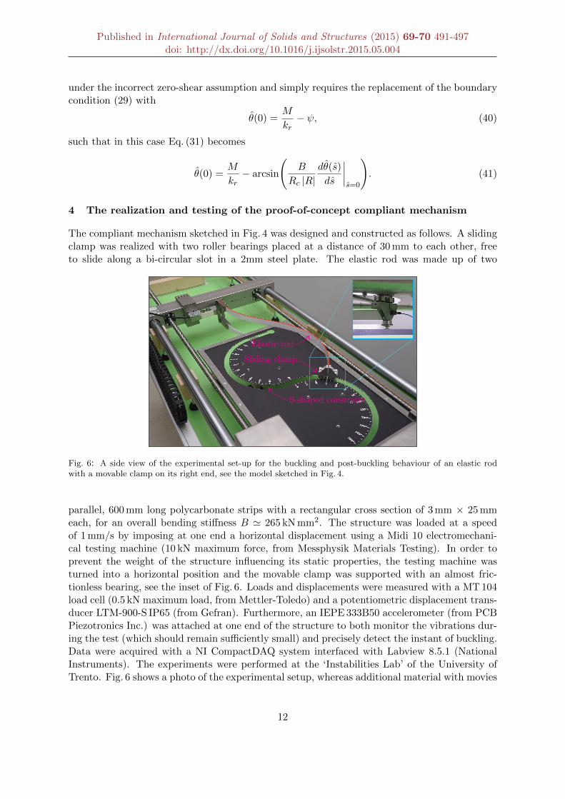
The compliant mechanism sketched in Fig. 4 was designed and constructed as follows. A slidingclamp was realized with two roller bearings placed at a distance of 30 mm to each other, freeto slide along a bi-circular slot in a 2mm steel plate. The elastic rod was made up of two
Sliding clamp
Elastic rod
S-shaped constraint
Fig. 6: A side view of the experimental set-up for the buckling and post-buckling behaviour of an elastic rodwith a movable clamp on its right end, see the model sketched in Fig. 4.
parallel, 600 mm long polycarbonate strips with a rectangular cross section of 3 mm × 25 mmeach, for an overall bending stiffness B ' 265 kN mm2. The structure was loaded at a speedof 1 mm/s by imposing at one end a horizontal displacement using a Midi 10 electromechani-cal testing machine (10 kN maximum force, from Messphysik Materials Testing). In order toprevent the weight of the structure influencing its static properties, the testing machine wasturned into a horizontal position and the movable clamp was supported with an almost fric-tionless bearing, see the inset of Fig. 6. Loads and displacements were measured with a MT 104load cell (0.5 kN maximum load, from Mettler-Toledo) and a potentiometric displacement trans-ducer LTM-900-S IP65 (from Gefran). Furthermore, an IEPE 333B50 accelerometer (from PCBPiezotronics Inc.) was attached at one end of the structure to both monitor the vibrations dur-ing the test (which should remain sufficiently small) and precisely detect the instant of buckling.Data were acquired with a NI CompactDAQ system interfaced with Labview 8.5.1 (NationalInstruments). The experiments were performed at the ‘Instabilities Lab’ of the University ofTrento. Fig. 6 shows a photo of the experimental setup, whereas additional material with movies
12

Published in International Journal of Solids and Structures (2015) 69-70 491-497doi: http://dx.doi.org/10.1016/j.ijsolstr.2015.05.004
of the experiments is provided in the electronic supplementary material and can be found athttp://ssmg.unitn.it/.
F [
N]
20
40
60
0
-20
theoryexperiment
Ten
sion
! [m]-0.1-0.2-0.3 0 0.1
Com
pre
ssio
n
!"#F>0
R!
Fig. 7: The postcritical behaviour of the compliant mechanism sketched in Fig. 4, corresponding to the first modeunder tensile and compressive loads. In particular, the applied axial load F is shown versus the end displacementof the system δ. Note the flat, ‘almost neutral’ postcritical response in compression. The theoretical solution(reported dashed) has been calculated with Eq. (26), through steps (i.)-(iv.).
Results of tension/compression experiments are reported in Figs. 7, 8, and 9. In partic-ular, the applied load F versus end displacement δ relation is shown in Fig. 7. Here, besidethe remarkable agreement with the theoretical results (reported with a dashed line), we maynote that the structure stiffens during the postcritical behaviour in tension, but displays an‘almost neutral’ behaviour in compression. With ‘almost neutral’ it is meant that the externalload increases very weakly during compression, so that it remains almost constant while thedisplacement increases. For this reason, the mechanical system is very stiff up to the bucklingload in compression, but the load does not vary after this even if the displacement progresses bya large amount. We can therefore notice that the compliant system operates as a force limiter.
Deformed shapes of the elastica (photos taken during tension and compression) at differentloadings are reported in Fig. 8, while a comparison with theoretical results, denoted with adashed line, is shown in Fig. 9. Note the large displacements regime in which the compliant,elastic system operates and the excellent agreement between theory and experiments.
Conclusions
A proof-of-concept compliant mechanism has been designed, constructed and tested, in whichan elastic rod is constrained at one end with a clamp sliding along a curved and frictionlessprofile and loaded at the other end. The analyzed constraint introduces nontrivial boundaryconditions that strongly affects the elastica, which has been explicitly solved for the mechanicalsystem investigated. Experiments on this system have shown a remarkable agreement withmodelling and have opened the possibility of realizing an almost neutral mechanical device,
13

Published in International Journal of Solids and Structures (2015) 69-70 491-497doi: http://dx.doi.org/10.1016/j.ijsolstr.2015.05.004
30° 90°
120°90°
B)A) C) D)
Fig. 8: The deformed elastica during a compression (A and B) and a tension (C and D) test performed on thestructure sketched in Fig. 4.
60°
60°
A) B)
Fig. 9: The deformed shape predicted by the elastica (yellow/dashed line) superimposed on the experimentaldeformed shapes of the structure (red/solid line). Case (A) refers to compression, while (B) to tension.
that could be employed as a force limiter.
Acknowledgments
D.B., D.M. and D.Z. gratefully acknowledge financial support from the ERC Advanced Grant‘Instabilities and nonlocal multiscale modelling of materials’ FP7-PEOPLE-IDEAS-ERC-2013-AdG (2014-2019). G.N. acknowledges financial support from SISSA through the excellenceprogram NOFYSAS 2012.
References
[1] Audoly, B., Pomeau, B. 2010. Elasticity and geometry, Oxford University Press, Oxford.
[2] Biezeno, C.B., Grammel, R., 1955. Engineering dynamics. Blackie & Sons, London and Glasgow.
[3] Bigoni, D., Misseroni, D., Noselli, G., Zaccaria, D., 2012. Effects of the constraint’s curvature onstructural instability: tensile buckling and multiple bifurcations. Proc. R. Soc. A. 468, 2191-2209.(DOI: 10.1098/rspa.2011.0732)
14

Published in International Journal of Solids and Structures (2015) 69-70 491-497doi: http://dx.doi.org/10.1016/j.ijsolstr.2015.05.004
[4] Bigoni, D., Misseroni, D., Noselli, G., Zaccaria, D., 2013. Surprising instabilities of simple elastic structures,in: Kirillov, O.N., Pelinovsky, D.E. (Eds.), ‘Nonlinear Physical Systems - Spectral Analysis, Stability andBifurcations’. Wiley-ISTE, London, pp. 1-14. (ISBN: 978-1-84821-420-0).
[5] Bigoni, D., Bosi, F., Dal Corso, F., Misseroni, D., 2014 a. Instability of a penetrating blade. J. Mech. Phys.Solids, 64, 411-425. (DOI: 10.1016/j.jmps.2013.12.008)
[6] Bigoni, D., Dal Corso, F., Misseroni, D., Bosi, F., 2014 b. Torsional locomotion. Proc. R. Soc. A., 470,20140599. (DOI: 10.1098/rspa.2014.0599)
[7] Bigoni, D., Dal Corso, F., Bosi, F., Misseroni, D., 2015. Eshelby-like forces acting on elastic structures:theoretical and experimental proof. Mech. Materials, 80, 368-374. (DOI: 10.1016/j.mechmat.2013.10.009)
[8] Bosi, F., Misseroni, D., Dal Corso, F., Bigoni, D., 2014. An elastica arm scale. Proc. R. Soc. A., 470,20140232. (DOI: 10.1098/rspa.2014.0232)
[9] Byrd, P.F., Friedman, M.D., 1971. Handbook of elliptic integrals for engineers and scientists, second ed.Springer-Verlag, Berlin Heidelberg. (ISBN: 978-3-642-65140-3)
[10] Gajewski, A., Palej, R. 1974. Stability and shape optimization of an elastically clamped bar under tension(in Polish). Rozprawy Inzynierskie - Engineering Transactions, 22, 265-279.
[11] Love, A.E.H. (1927) A treatise on the mathematical theory of elasticity. Cambridge University Press.
[12] Timoshenko S.P. and Gere, J.M. (1936) Theory of elastic stability. McGraw-Hill.
[13] Zaccaria, D., Bigoni, D., Noselli, G., Misseroni, D., 2011. Structures buckling under tensile dead load. Proc.R. Soc. A. 467, 1686-1700. (DOI: 10.1098/rspa.2010.0505)
[14] Ziegler, H., 1977. Principles of structural stability. Birkauser Verlag.
[15] Zyczkowski, M. (1991) Strength of structural elements. Elsevier.
15