Embed Size (px)
Citation preview

Slide 12.1
© The McGraw-Hill Companies, 2007
Object-Oriented andClassical Software
Engineering
Seventh Edition, WCB/McGraw-Hill, 2007
Stephen R. [email protected]

Slide 12.2
© The McGraw-Hill Companies, 2007
CHAPTER 12
OBJECT-ORIENTEDANALYSIS

Slide 12.3
© The McGraw-Hill Companies, 2007
Overview
The analysis workflow Extracting the entity classes Object-oriented analysis: The elevator problem
case study Functional modeling: The elevator problem case
study Entity class modeling: The elevator problem case
study Dynamic modeling: The elevator problem case
study The test workflow: Object-oriented analysis

Slide 12.4
© The McGraw-Hill Companies, 2007
Overview (contd)
Extracting the boundary and control classes The initial functional model: The MSG Foundation
case study The initial class diagram: The MSG Foundation
case study The initial dynamic model: The MSG Foundation
case study Extracting the boundary classes: The MSG
Foundation case study Extracting the boundary classes: The MSG
Foundation case study

Slide 12.5
© The McGraw-Hill Companies, 2007
Overview (contd)
Refining the use cases: The MSG Foundationcase study
Use-case realization: The MSG Foundation casestudy
Incrementing the class diagram: The MSGFoundation case study
The specification document in the Unified Process More on actors and use cases CASE tools for the object-oriented analysis
workflow Challenges of the object-oriented analysis
workflow

Slide 12.6
© The McGraw-Hill Companies, 2007
Object-Oriented Analysis
OOA is a semiformal analysis technique for theobject-oriented paradigmThere are over 60 equivalent techniquesToday, the Unified Process is the only viable
alternative
During this workflowThe classes are extracted
RemarkThe Unified Process assumes knowledge of class
extraction

Slide 12.7
© The McGraw-Hill Companies, 2007
12.1 The Analysis Workflow
The analysis workflow has two aimsObtain a deeper understanding of the requirementsDescribe them in a way that will result in a maintainable
design and implementation

Slide 12.8
© The McGraw-Hill Companies, 2007
The Analysis Workflow (contd)
There are three types of classes:
Entity classes
Boundary classes
Control classes

Slide 12.9
© The McGraw-Hill Companies, 2007
The Analysis Workflow (contd)
Entity classModels long-lived information
Examples: Account Class Investment Class

Slide 12.10
© The McGraw-Hill Companies, 2007
The Analysis Workflow (contd)
Boundary classModels the interaction between the product and the
environmentA boundary class is generally associated with input or
output
Examples: Investments Report ClassMortgages Report Class

Slide 12.11
© The McGraw-Hill Companies, 2007
The Analysis Workflow (contd)
Control classModels complex computations and algorithms
Example:Estimate Funds for Week Class

Slide 12.12
© The McGraw-Hill Companies, 2007
UML Notation for These Three Class Types
Stereotypes (extensions of UML)
Figure 12.1

Slide 12.13
© The McGraw-Hill Companies, 2007
12.2 Extracting the Entity Classes
Perform the following three steps incrementallyand iterativelyFunctional modeling
Present scenarios of all the use cases (a scenario is an instanceof a use case)
Class modeling Determine the entity classes and their attributes Determine the interrelationships and interactions between the
entity classes Present this information in the form of a class diagram
Dynamic modeling Determine the operations performed by or to each entity class Present this information in the form of a statechart

Slide 12.14
© The McGraw-Hill Companies, 2007
12.3 Object-Oriented Analysis: The Elevator Problem Case Study
A product is to be installed to control n elevators in a buildingwith m floors. The problem concerns the logic required tomove elevators between floors according to the followingconstraints:1. Each elevator has a set of m buttons, one for each floor.These illuminate when pressed and cause the elevator to visitthe corresponding floor. The illumination is canceled whenthe corresponding floor is visited by the elevator2. Each floor, except the first and the top floor, has twobuttons, one to request an up-elevator, one to request adown-elevator. These buttons illuminate when pressed. Theillumination is canceled when an elevator visits the floor, thenmoves in the desired direction3. If an elevator has no requests, it remains at its currentfloor with its doors closed

Slide 12.15
© The McGraw-Hill Companies, 2007
12.4 Functional Modeling: The Elevator Problem Case Study
A use case describes the interaction betweenThe product, andThe actors (external users)

Slide 12.16
© The McGraw-Hill Companies, 2007
Use Cases
For the elevator problem, there are only twopossible use cases Press an Elevator Button, and Press a Floor Button
Figure 12.2

Slide 12.17
© The McGraw-Hill Companies, 2007
Scenarios
A use case provides a generic description of theoverall functionality
A scenario is an instance of a use case
Sufficient scenarios need to be studied to get acomprehensive insight into the target productbeing modeled

Slide 12.18
© The McGraw-Hill Companies, 2007
Normal Scenario: Elevator Problem
Figure 12.3

Slide 12.19
© The McGraw-Hill Companies, 2007
Exception Scenario: Elevator Problem
Figure 12.4

Slide 12.20
© The McGraw-Hill Companies, 2007
12.5 Entity Class Modeling : The Elevator Problem Case Study
Extract classes and their attributesRepresent them using a UML diagram
One alternative: Deduce the classes from usecases and their scenariosPossible danger: Often there are many scenarios, and
henceToo many candidate classes
Other alternatives:CRC cards (if you have domain knowledge)Noun extraction

Slide 12.21
© The McGraw-Hill Companies, 2007
12.5.1 Noun Extraction
A two-stage process
Stage 1. Concise problem definitionDescribe the software product in single paragraphButtons in elevators and on the floors control the
movement of n elevators in a building with m floors.Buttons illuminate when pressed to request the elevatorto stop at a specific floor; the illumination is canceledwhen the request has been satisfied. When an elevatorhas no requests, it remains at its current floor with itsdoors closed

Slide 12.22
© The McGraw-Hill Companies, 2007
Noun Extraction (contd)
Stage 2. Identify the nounsIdentify the nouns in the informal strategyButtons in elevators and on the floors control the
movement of n elevators in a building with m floors.Buttons illuminate when pressed to request the elevatorto stop at a specific floor; the illumination is canceledwhen the request has been satisfied. When an elevatorhas no requests, it remains at its current floor with itsdoors closed
Use the nouns as candidate classes

Slide 12.23
© The McGraw-Hill Companies, 2007
Noun Extraction (contd)
Nounsbutton, elevator, floor, movement, building, illumination, request,
door
floor, building, door are outside the problem boundary —exclude
movement, illumination, request are abstract nouns —exclude (they may become attributes)
Candidate classes:Elevator Class and Button Class
Subclasses:Elevator Button Class and Floor Button Class

Slide 12.24
© The McGraw-Hill Companies, 2007
First Iteration of Class Diagram
ProblemButtons do not communicate directly with elevatorsWe need an additional class: Elevator Controller Class
Figure 12.5

Slide 12.25
© The McGraw-Hill Companies, 2007
Second Iteration of Class Diagram
All relationshipsare now 1-to-nThis makes
design andimplementationeasier
Figure 12.6

Slide 12.26
© The McGraw-Hill Companies, 2007
12.5.2 CRC Cards
Used since 1989 for OOA
For each class, fill in a card showingName of ClassFunctionality (Responsibility)List of classes it invokes (Collaboration)
Now CRC cards are automated (CASE toolcomponent)

Slide 12.27
© The McGraw-Hill Companies, 2007
CRC Cards (contd)
StrengthWhen acted out by team members, CRC cards are a
powerful tool for highlighting missing or incorrect items
WeaknessIf CRC cards are used to identify entity classes, domain
expertise is needed

Slide 12.28
© The McGraw-Hill Companies, 2007
12.6 Dynamic Modeling: The Elevator Problem Case Study
Produce aUMLstatechart
State,event, andpredicatearedistributedover thestatechart
Figure 12.7

Slide 12.29
© The McGraw-Hill Companies, 2007
Dynamic Modeling: Elevator Problem (contd)
This UML statechart is equivalent to the statetransition diagram of Figures 11.15 through 11.17
This is shown by considering specific scenarios
In fact, a statechart is constructed by modeling theevents of the scenarios

Slide 12.30
© The McGraw-Hill Companies, 2007
12.7 The Test Workflow: Object-Oriented Analysis
CRC cards arean excellenttesting technique
Figure 12.8

Slide 12.31
© The McGraw-Hill Companies, 2007
CRC Cards
Consider responsibility1. Turn on elevator button
This is totally inappropriate for the object-orientedparadigmResponsibility-driven design has been ignoredInformation hiding has been ignored
Responsibility1. Turn on elevator button
should be1. Send message to Elevator Button Class to turn itself on

Slide 12.32
© The McGraw-Hill Companies, 2007
CRC Cards (contd)
Also, a class has been overlooked
The elevator doors have a state that changesduring execution (class characteristic)Add class Elevator Doors ClassSafety considerations
Modify the CRC card

Slide 12.33
© The McGraw-Hill Companies, 2007
Second Iteration of the CRC Card
Figure 12.9

Slide 12.34
© The McGraw-Hill Companies, 2007
CRC Cards (contd)
Having modified the class diagram, reconsider theUse-case diagram (no change)Class diagram (see the next slide)StatechartsScenarios (see the slide after the next slide)

Slide 12.35
© The McGraw-Hill Companies, 2007
Third Iteration of Class Diagram
Figure 12.10

Slide 12.36
© The McGraw-Hill Companies, 2007
Second Iteration of the Normal Scenario:
Figure 12.11

Slide 12.37
© The McGraw-Hill Companies, 2007
OOA: Elevator Problem (contd)
The object-oriented analysis is now fine
We should rather say:The object-oriented analysis is fine for now
We may need to return to the object-orientedanalysis workflow during the object-orienteddesign workflow

Slide 12.38
© The McGraw-Hill Companies, 2007
12.8 Extracting the Boundary and Control Classes
EachInput screen,Output screen, andReport
is modeled by its own boundary class
Each nontrivial computation is modeled by acontrol class

Slide 12.39
© The McGraw-Hill Companies, 2007
12.9 The Initial Functional Model: MSG Foundation
l Recall the seventh iteration of the use-case diagram
Figure 12.12

Slide 12.40
© The McGraw-Hill Companies, 2007
Use Case Manage a Mortgage
One possible extended scenario
Figure 12.13

Slide 12.41
© The McGraw-Hill Companies, 2007
Use Case Manage a Mortgage (contd)
A second extended scenario
Figure 12.14

Slide 12.42
© The McGraw-Hill Companies, 2007
Use Case Estimate Funds Available for Week
One possible scenario
Figure 12.15

Slide 12.43
© The McGraw-Hill Companies, 2007
Use Case Produce a Report
One possible scenario
Figure 12.16

Slide 12.44
© The McGraw-Hill Companies, 2007
Use Case Produce a Report (contd)
Another possible scenario
Figure 12.17

Slide 12.45
© The McGraw-Hill Companies, 2007
12.10 The Initial Class Diagram: MSG Foundation
The aim of entity modeling step is to extract theentity classes, determine their interrelationships,and find their attributes
Usually, the best way to begin this step is to usethe two-stage noun extraction method

Slide 12.46
© The McGraw-Hill Companies, 2007
Noun Extraction: MSG Foundation
Stage 1: Describe the information system in asingle paragraphWeekly reports are to be printed showing how much
money is available for mortgages. In addition, lists ofinvestments and mortgages must be printed ondemand.

Slide 12.47
© The McGraw-Hill Companies, 2007
Noun Extraction: MSG Foundation (contd)
Stage 2: Identify the nouns in this paragraphWeekly reports are to be printed showing how much
money is available for mortgages. In addition, lists ofinvestments and mortgages must be printed ondemand.
The nouns are report, money, mortgage, list, andinvestment

Slide 12.48
© The McGraw-Hill Companies, 2007
Noun Extraction: MSG Foundation (contd)
Nouns report and list are not long lived, so they areunlikely to be entity classes (report will surely turnout to be a boundary class)
money is an abstract noun
This leaves two candidate entity classesMortgage Class and Investment Class

Slide 12.49
© The McGraw-Hill Companies, 2007
First Iteration of the Initial Class Diagram
Figure 12.18

Slide 12.50
© The McGraw-Hill Companies, 2007
Second Iteration of the Initial Class Diagram
Operations performed on the two entity classesare likely to be very similarInsertions, deletions, and modificationsAll members of both entity classes have to be printed on
demand
Mortgage Class and Investment Class should besubclasses of a superclass called Asset Class

Slide 12.51
© The McGraw-Hill Companies, 2007
Second Iteration of Initial Class Diagram (contd)
Figure 12.19

Slide 12.52
© The McGraw-Hill Companies, 2007
Back to the Requirements Workflow
The current five use cases include Manage a Mortgageand Manage an Investment
These two can now be combined into a single usecase, Manage an Asset

Slide 12.53
© The McGraw-Hill Companies, 2007
Eighth Iteration of the Use-Case Diagram
The new use case is shaded
Figure 12.20

Slide 12.54
© The McGraw-Hill Companies, 2007
Initial Class Diagram: MSG Foundation (contd)
Finally, we add the attributes of each class to theclass diagramFor the MSG Foundation case study, the result is shown
on the next slide
The empty rectangle at the bottom of each box willlater be filled with the operations of that class

Slide 12.55
© The McGraw-Hill Companies, 2007
Second Iteration of Initial Class Diagram (contd)
Figure 12.21

Slide 12.56
© The McGraw-Hill Companies, 2007
Iteration and Incrementation
The phrase “iterate and increment” also includesthe possibility of having to decrement what hasbeen developed to dateA mistake may have been made, and backtracking is
neededAs a consequence of reorganizing the UML models,
one or more artifacts may have become superfluous

Slide 12.57
© The McGraw-Hill Companies, 2007
12.11 The Initial Dynamic Model: MSG Foundation
Dynamic modeling is the third step in extractingthe entity classes
A statechart is constructed that reflects all theoperations performed by or to the software product
The operations are determined from the scenarios

Slide 12.58
© The McGraw-Hill Companies, 2007
Initial Dynamic Model: MSG Foundation (contd)
Figure 12.22

Slide 12.59
© The McGraw-Hill Companies, 2007
Initial Dynamic Model: MSG Foundation (contd)
The statechart reflects the operations of thecomplete MSG Foundation information systemThe solid circle on the top left represents the initial
state, the starting point of the statechartThe white circle containing the small black circle on the
top right represents the final stateStates other than the initial and final states are
represented by rectangles with rounded cornersThe arrows represent possible transitions from state to
state

Slide 12.60
© The McGraw-Hill Companies, 2007
Initial Dynamic Model: MSG Foundation (contd)
In state MSG Foundation Information SystemLoop, one of five events can occur
An MSG staff member can issue one of fivecommands:estimate funds for the weekmanage an assetupdate estimated annual operating expensesproduce a report, orquit

Slide 12.61
© The McGraw-Hill Companies, 2007
Initial Dynamic Model: MSG Foundation (contd)
These possibilities are indicated by the five eventsestimate funds for the week selectedmanage an asset selectedupdate estimated annual operating expenses selectedproduce a report selected, andquit selected
An event causes a transition between states

Slide 12.62
© The McGraw-Hill Companies, 2007
Initial Dynamic Model: MSG Foundation (contd)
An MSG staff member selects an option byclicking on the menu
This graphical user interface (GUI) requiresspecial software
Figure 12.23

Slide 12.63
© The McGraw-Hill Companies, 2007
Initial Dynamic Model: MSG Foundation (contd)
Equivalent textual user interface that can run onany computer
Figure 12.24

Slide 12.64
© The McGraw-Hill Companies, 2007
12.12 Revising the Entity Classes: MSG Foundation
The initial functional model, the initial classdiagram, and the initial dynamic model arecompletedChecking them reveals a fault
In the initial statechart, consider state UpdateEstimated Annual Operating Expenses withoperation Update the estimated annual operating expenses
This operation has to be performed on the current valueof the estimated annual operating expense

Slide 12.65
© The McGraw-Hill Companies, 2007
Revising the Entity Classes: MSG Foundation (contd)
But where is the value of the estimated annualoperating expenses to be found?
Currently there is only one class (Asset Class)and its two subclassesNeither is appropriate for storing the estimated annual
operating expenses

Slide 12.66
© The McGraw-Hill Companies, 2007
Revising the Entity Classes: MSG Foundation (contd)
The only way a value can be stored on a long-termbasis is as an attribute of an instance of that classor its subclasses
Another entity class is needed for storing theestimated annual operating expensesMSG Application Class

Slide 12.67
© The McGraw-Hill Companies, 2007
Third Iteration of the Initial Class Diagram: MSG Foundation
MSGApplicationClasshas otherattributes aswellAttributes
that do notappertain tothe assets
Figure 12.25

Slide 12.68
© The McGraw-Hill Companies, 2007
Third Iteration of the Initial Class Diagram: MSG Foundation
l The class diagram redrawn to show the prototypes
Figure 12.26

Slide 12.69
© The McGraw-Hill Companies, 2007
12.13 Extracting the Boundary Classes: MSG Foundation
It is usually easy to extract boundary classesEach input screen, output screen, and printed report is
generally modeled by a boundary class
One screen should be adequate for all four MSGFoundation use cases
Estimate Funds Available for Week
Manage an Asset
Update Estimated Annual Operating Expenses
Produce a Report
Accordingly there is one initial boundary classUser Interface Class

Slide 12.70
© The McGraw-Hill Companies, 2007
Extracting Boundary Classes: MSG Foundation (contd)
Three reports have to be printedThe estimated funds for the week reportThe listing of all mortgagesThe listing of all investments
Each of these has to be modeled by a separateboundary classEstimated Funds Report ClassMortgages Report ClassInvestments Report Class

Slide 12.71
© The McGraw-Hill Companies, 2007
Extracting Boundary Classes: MSG (contd)
Here are the four initial boundary classes
Figure 12.27

Slide 12.72
© The McGraw-Hill Companies, 2007
Initial Boundary Classes: MSG Foundation (contd)
There are three reports:The purchases reportThe sales reportThe future trends report
The content of each report is differentEach report therefore has to be modeled by a separate
boundary class

Slide 12.73
© The McGraw-Hill Companies, 2007
12.14 Extracting the Control Classes: MSG Foundation
Each computation is usually modeled by a controlclass
The MSG Foundation case study has just oneEstimate the funds available for the week
There is one initial control class
Figure 12.28

Slide 12.74
© The McGraw-Hill Companies, 2007
The description of class extraction is complete
We now therefore return to the Unified Process
Class Extraction (contd)

Slide 12.75
© The McGraw-Hill Companies, 2007
12.15 Use-Case Realization: The MSG Foundation Case Study
The process of extending and refining use cases iscalled use-case realization

Slide 12.76
© The McGraw-Hill Companies, 2007
Use-Case Realization (contd)
The verb “realize” is used at least 3 different ways:Understand (“Harvey slowly began to realize that he
was in the wrong classroom”);Receive (“Ingrid will realize a profit of $45,000 on the
stock transaction”); andAccomplish (“Janet hopes to realize her dream of
starting a computer company”)
In the phrase “realize a use case,” the word“realize” is used in this last sense

Slide 12.77
© The McGraw-Hill Companies, 2007
Use-Case Realization (contd)
The realization of a specific scenario of a use caseis depicted using an interaction diagramEither a sequence diagram or collaboration diagram
Consider use case Estimate Funds Available forWeek
We have previously seenThe use caseThe description of the use case
Slide 12.78
© The McGraw-Hill Companies, 2007
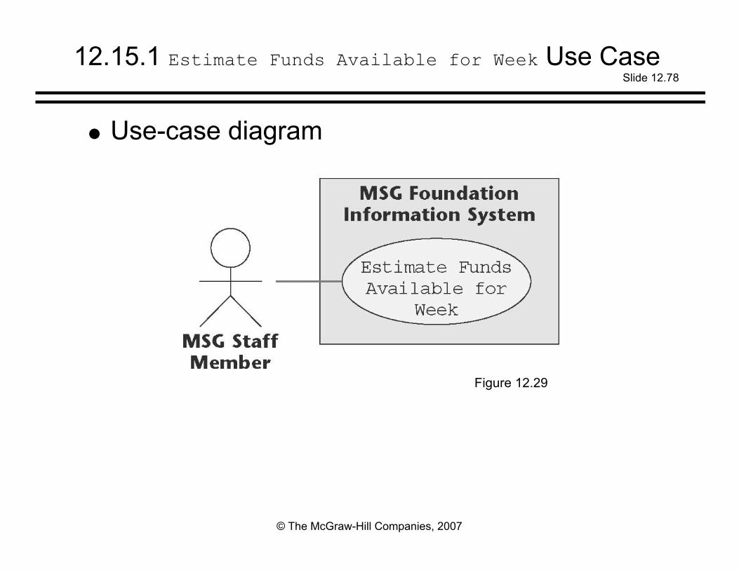
12.15.1 Estimate Funds Available for Week Use Case
Use-case diagram
Figure 12.29

Slide 12.79
© The McGraw-Hill Companies, 2007
Estimate Funds Available for Week Use Case (contd)
Descriptionof use case
Figure 12.30

Slide 12.80
© The McGraw-Hill Companies, 2007
Estimate Funds Available for Week Use Case (contd)
Class diagram (classes that enter into the usecase)
Figure 12.31

Slide 12.81
© The McGraw-Hill Companies, 2007
Estimate Funds Available for Week Use Case (contd)
The six classes that enter into this use case are:User Interface Class
This class models the user interface
Estimate Funds for Week Class This control class models the computation of the estimate of the
funds that are available to fund mortgages during that week
Mortgage Class This class models the estimated grants and payments for the week
Investment Class This class models the estimated return on investments for the
week
MSG Application Class This class models the estimated return on investments for the
week
Estimated Funds Report Class This class models the printing of the report

Slide 12.82
© The McGraw-Hill Companies, 2007
Estimate Funds Available for Week Use Case (contd)
Scenario (one possible instance of the use case)
Figure 12.32

Slide 12.83
© The McGraw-Hill Companies, 2007
Estimate Funds Available for Week Use Case (contd)
A working information system uses objects, notclassesExample: A specific mortgage cannot be represented
by Mortgage Class but rather by an object, a specificinstance of Mortgage Class
Such an object is denoted by : Mortgage Class

Slide 12.84
© The McGraw-Hill Companies, 2007
Estimate Funds Available for Week Use Case (contd)
A class diagram shows the classes in the use caseand their relationshipsIt does not show the objects nor the sequence of
messages as they are sent from object to object
Something more is needed

Slide 12.85
© The McGraw-Hill Companies, 2007
Estimate Funds Available for Week Use Case (contd)
Collaboration diagram (of the realization of thescenario of the use case)
Figure 12.33

Slide 12.86
© The McGraw-Hill Companies, 2007
Estimate Funds Available for Week Use Case (contd)
The collaboration diagram shows the objects aswell as the messages, numbered in the order inwhich they are sent in the specific scenario

Slide 12.87
© The McGraw-Hill Companies, 2007
Estimate Funds Available for Week Use Case (contd)
Item 1:The staff member wants to compute the funds available
for the weekIn the collaboration diagram, this is modeled by
message 1: Request estimate of funds available for week
from MSG Staff Member to : User Interface Class, aninstance of User Interface Class

Slide 12.88
© The McGraw-Hill Companies, 2007
Estimate Funds Available for Week Use Case (contd)
Item 2This request is passed on to : Estimate Funds for
Week Class, an instance of the control class thatactually performs the calculation
This is modeled by message 2: Transfer request
Four separate financial estimates are nowdetermined by : Estimate Funds for Week Class

Slide 12.89
© The McGraw-Hill Companies, 2007
Estimate Funds Available for Week Use Case (contd)
Item 3In Step 1 of the scenario, the estimated annual return
on investments is summed for each investment and theresult divided by 52
This extraction of the estimated weekly return ismodeled by message 3: Request estimated return on investments for week
from : Estimate Funds for Week Class to: Investment Class followed by message 4: Return estimated weekly return on investments
in the other direction

Slide 12.90
© The McGraw-Hill Companies, 2007
Estimate Funds Available for Week Use Case (contd)
Item 4In Step 2 of the scenario, the weekly operating
expenses are estimated by taking the estimated annualoperating expenses and dividing by 52
This extraction of the weekly expenses is modeled bymessage 5: Request estimated operating expenses for week
from : Estimate Funds for Week Class to : MSGApplication Class followed by message 6: Return estimated operating expenses for week
in the other direction

Slide 12.91
© The McGraw-Hill Companies, 2007
Estimate Funds Available for Week Use Case (contd)
Item 5In Steps 3, 4, and 5 of the scenario, two estimates are
determined the estimated grants for the week, and the estimated payments for the week
This is modeled by message 7: Request estimated grants and payments for week
from : Estimate Funds for Week Class to : MortgageClass, and by message 8: Return estimated grants and payments for week
in the other direction

Slide 12.92
© The McGraw-Hill Companies, 2007
Estimate Funds Available for Week Use Case (contd)
Item 6Now the arithmetic computation of Step 6 of the
scenario is performedThis is modeled by message
9: Compute estimated amount available for week
This is a self call: Estimate Funds for Week Class tells itself to perform
the calculationThe result of the computation is stored in : MSG
Application Class by message 10: Transfer estimated amount available for week

Slide 12.93
© The McGraw-Hill Companies, 2007
Estimate Funds Available for Week Use Case (contd)
Item 7The result is printed in Step 7 of the scenarioThis is modeled by message
11: Print estimated amount available
from : MSG Application Class to : Estimated FundsReport Class

Slide 12.94
© The McGraw-Hill Companies, 2007
Estimate Funds Available for Week Use Case (contd)
Item 8Finally, an acknowledgment is sent to the MSG staff
member that the task has been successfully completedThis is modeled by messages
12: Send successful completion message 13: Send successful completion message 14: Transfer successful completion message, and 15: Display successful completion message

Slide 12.95
© The McGraw-Hill Companies, 2007
Estimate Funds Available for Week Use Case (contd)
No client will approve the specification documentwithout understanding it
Accordingly, a written description of thecollaboration diagram is needed, the flow of events

Slide 12.96
© The McGraw-Hill Companies, 2007
Estimate Funds Available for Week Use Case (contd)
The flow of events of the collaboration diagram ofthe realization of the scenario of the use case
Figure 12.34
Slide 12.97
© The McGraw-Hill Companies, 2007
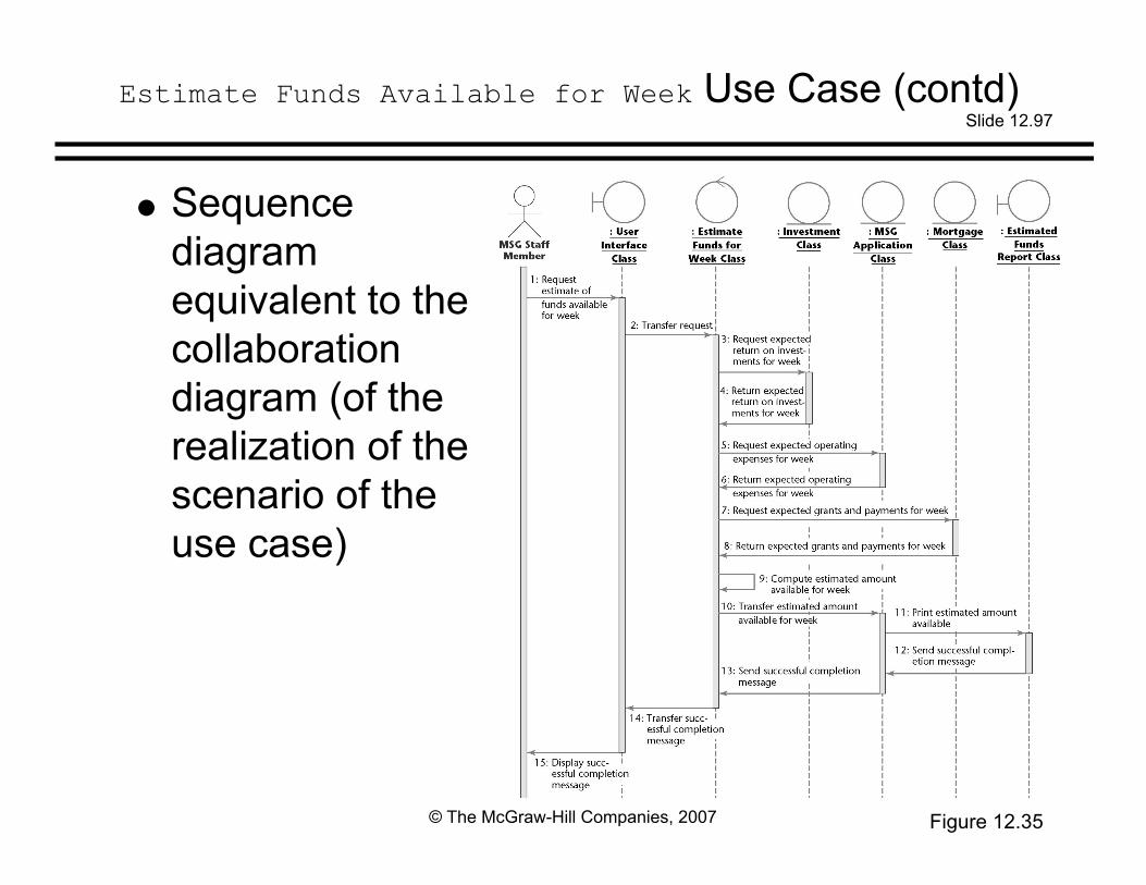
Estimate Funds Available for Week Use Case (contd)
Sequencediagramequivalent to thecollaborationdiagram (of therealization of thescenario of theuse case)
Figure 12.35

Slide 12.98
© The McGraw-Hill Companies, 2007
Interaction Diagrams
The strength of a sequence diagram is that itshows the flow of messages and their orderunambiguouslyWhen transfer of information is the focus of attention, a
sequence diagram is superior to a collaboration diagram
A collaboration diagram is similar to a classdiagramWhen the developers are concentrating on the classes,
a collaboration diagram is more useful than theequivalent sequence diagram

Slide 12.99
© The McGraw-Hill Companies, 2007
Estimate Funds Available for Week Use Case (contd)
Figures 12.29 through 12.35 do not depict arandom collection of UML artifacts
Instead, these figures depict a use case andartifacts derived from that use case
In more detail (see next slide):

Slide 12.100
© The McGraw-Hill Companies, 2007
Estimate Funds Available for Week Use Case (contd)
Figure 12.29 depicts the use case Estimate FundsAvailable for Week
The figure modelsAll possible sets of interactionsBetween the actor MSG Staff Member (external to the
software product) and the MSG Foundation softwareproduct itself
That relate to the action of estimating funds available forthe week

Slide 12.101
© The McGraw-Hill Companies, 2007
Estimate Funds Available for Week Use Case (contd)
Figure 12.30 is the description of that use case
The figure provides a written account of the detailsof the Estimate Funds Available for Week use case ofFigure 12.29

Slide 12.102
© The McGraw-Hill Companies, 2007
Estimate Funds Available for Week Use Case (contd)
Figure 12.31 is a class diagram showing theclasses that realize the Estimate Funds Available forWeek use case
The figure depictsThe classes that are needed to model all possible
scenarios of the use caseTogether with their interactions

Slide 12.103
© The McGraw-Hill Companies, 2007
Estimate Funds Available for Week Use Case (contd)
Figure 12.32 is a scenario
It depicts one specific instance of the use case ofFigure 12.29

Slide 12.104
© The McGraw-Hill Companies, 2007
Estimate Funds Available for Week Use Case (contd)
Figure 12.33 is a collaboration diagram of therealization of the scenario of Figure 12.32
The figure depicts the objects and the messagessent between them in the realization of that onespecific scenario

Slide 12.105
© The McGraw-Hill Companies, 2007
Estimate Funds Available for Week Use Case (contd)
Figure 12.34 is the flow of events of thecollaboration diagram of the realization of thescenario of Figure 12.32
Figure 12.34 is a written description of therealization of the scenario of Figure 12.32
(Compare: Figure 12.30 is a written description of theEstimate Funds Available for Week use case of Figure12.29)

Slide 12.106
© The McGraw-Hill Companies, 2007
Estimate Funds Available for Week Use Case (contd)
Figure 12.35 is the sequence diagram that is fullyequivalent to the collaboration diagram of Figure12.33
The sequence diagram depicts the objects and themessages sent between them in the realization ofthe scenario of Figure 12.32
Its flow of events is therefore also shown in Figure12.34

Slide 12.107
© The McGraw-Hill Companies, 2007
12.5.2 Manage an Asset Use Case
Use case
Figure 12.36

Slide 12.108
© The McGraw-Hill Companies, 2007
Description of use case
Manage an Asset Use Case (contd)
Figure 12.37

Slide 12.109
© The McGraw-Hill Companies, 2007
Manage an Asset Use Case (contd)
Class diagram showing the classes that realize theuse case
Figure 12.38

Slide 12.110
© The McGraw-Hill Companies, 2007
Manage an Asset Use Case (contd)
One scenario of the use case
Figure 12.39

Slide 12.111
© The McGraw-Hill Companies, 2007
Manage an Asset Use Case (contd)
Collaboration diagram of the realization of thescenario of the use case
Figure 12.40
Slide 12.112
© The McGraw-Hill Companies, 2007
Manage an Asset Use Case (contd)
Object : Investment Class does not play an activerole in this collaboration diagramThis scenario does not involve an investment, only a
mortgage
Actor Borrowers does not play a role in this usecase, either

Slide 12.113
© The McGraw-Hill Companies, 2007
Manage an Asset Use Case (contd)
l Sequence diagram equivalent to the collaborationdiagram (of the realization of the scenario of the usecase)
Figure 12.41

Slide 12.114
© The McGraw-Hill Companies, 2007
Manage an Asset Use Case (contd)
A different scenario of the use case
Figure 12.42

Slide 12.115
© The McGraw-Hill Companies, 2007
Manage an Asset Use Case (contd)
Collaboration diagram of the realization of thescenario of the use case
Figure 12.43

Slide 12.116
© The McGraw-Hill Companies, 2007
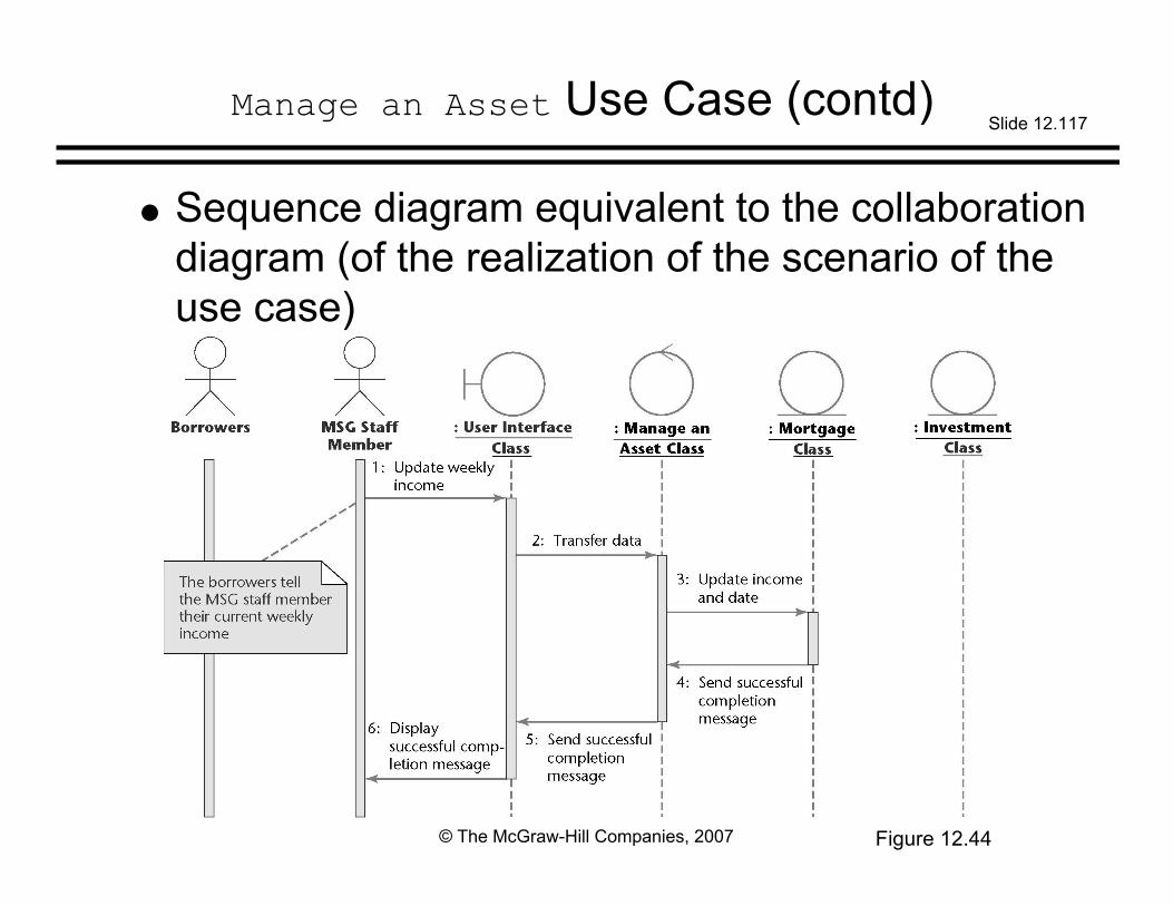
Manage an Asset Use Case (contd)
At the request of the borrowers, the MSG staffmember updates the weekly income of a couple
The scenario is initiated by the Borrowers
Their data are entered into the software product bythe MSG Staff MemberThis is stated in the note in the collaboration diagram
Slide 12.117
© The McGraw-Hill Companies, 2007
Manage an Asset Use Case (contd)
Sequence diagram equivalent to the collaborationdiagram (of the realization of the scenario of theuse case)
Figure 12.44

Slide 12.118
© The McGraw-Hill Companies, 2007
Manage an Asset Use Case (contd)
Two different scenarios of the same use casehave been presented
The use case is the sameThe class diagram is therefore the same
However, the collaboration (and sequence)diagrams reflect the differences between the twoscenarios

Slide 12.119
© The McGraw-Hill Companies, 2007
Manage an Asset Use Case (contd)
Boundary class User Interface Class appears inall the realizationsThe same screen will be used for all commands of the
information system
Revised menu
Figure 12.45

Slide 12.120
© The McGraw-Hill Companies, 2007
Manage an Asset Use Case (contd)
Corresponding textual interface
Figure 12.46

Slide 12.121
© The McGraw-Hill Companies, 2007
Update Annual Operating Expenses Use Case
Class diagram
Figure 12.47

Slide 12.122
© The McGraw-Hill Companies, 2007
Update Annual Operating Expenses Use Case (contd)
Collaboration diagram of a realization of ascenario of the use case
Figure 12.48

Slide 12.123
© The McGraw-Hill Companies, 2007
Update Annual Operating Expenses Use Case (contd)
Equivalent sequence diagram
Figure 12.49

Slide 12.124
© The McGraw-Hill Companies, 2007
12.15.4 Produce a Report Use Case
Use case
Figure 12.50

Slide 12.125
© The McGraw-Hill Companies, 2007
Produce a Report Use Case (contd)
Description of use case
Figure 12.51

Slide 12.126
© The McGraw-Hill Companies, 2007
Produce a Report Use Case (contd)
Class diagram
Figure 12.52

Slide 12.127
© The McGraw-Hill Companies, 2007
Produce a Report Use Case (contd)
One scenario of the use case
Figure 12.53

Slide 12.128
© The McGraw-Hill Companies, 2007
Produce a Report Use Case (contd)
CollaborationdiagramMortgages
(but notinvestments)are involved
Figure 12.54

Slide 12.129
© The McGraw-Hill Companies, 2007
Produce a Report Use Case (contd)
Sequence diagram
Figure 12.55

Slide 12.130
© The McGraw-Hill Companies, 2007
Produce a Report Use Case (contd)
A second scenario (listing all investments) of theuse case
Figure 12.56

Slide 12.131
© The McGraw-Hill Companies, 2007
Produce a Report Use Case (contd)
Collaborationdiagram forsecondscenarioThis time,
investments(but notmortgages)are involved
Figure 12.57

Slide 12.132
© The McGraw-Hill Companies, 2007
Produce a Report Use Case (contd)
Sequence diagram for second scenario
Figure 12.58

Slide 12.133
© The McGraw-Hill Companies, 2007
12.16 Incrementing the Class Diagram: The MSG Foundation
In the course of realizing the various use casesInterrelationships between classes become apparent
Accordingly, we now combine the realization classdiagrams

Slide 12.134
© The McGraw-Hill Companies, 2007
Combining the Realization Class Diagrams
Figure 12.59

Slide 12.135
© The McGraw-Hill Companies, 2007
Fifth iteration + realization class diagram
Fourth Iteration of the Class Diagram
Figure 12.60

Slide 12.136
© The McGraw-Hill Companies, 2007
As with the classical paradigm, the SPMP is drawnup at this pointIt appears in Appendix FThe plan conforms to the IEEE SPMP format
Software Project Management Plan

Slide 12.137
© The McGraw-Hill Companies, 2007
CRC cards are used to check the entity classes
All the artifacts are then inspected
12.17 The Test Workflow: MSG Foundation

Slide 12.138
© The McGraw-Hill Companies, 2007
12.18 The Specification Document in the Unified Process
The Unified Process is use-case drivenThe use cases and the artifacts derived from them
replace the traditional textual specification document
The client must be shown each use case andassociated artifacts, both diagrammatic and textualThese UML diagrams convey to the client more
information more accurately than the traditionalspecification document
The set of UML diagrams can also play the samecontractual role as the traditional specification document

Slide 12.139
© The McGraw-Hill Companies, 2007
The Specification Document (contd)
A scenario is a specific execution sequence
The client can therefore appreciate how theproduct works equally well fromA use case together with its scenarios, orA rapid prototype
The difference isThe use cases are successively refined, with more
information added each time, whereasThe rapid prototype is discarded

Slide 12.140
© The McGraw-Hill Companies, 2007
The Specification Document (contd)
However, a rapid prototype of the user interface isrequiredSpecimen screens and reports are needed (not a
complete rapid prototype)

Slide 12.141
© The McGraw-Hill Companies, 2007
12.19 More on Actors and Use Cases
To find the actors, consider every role in which anindividual can interact with the software productExample: Applicants, Borrowers
Actors are not individualsThey are roles played by those individuals
Find all the different roles played by each userFrom the list of roles, extract the actors

Slide 12.142
© The McGraw-Hill Companies, 2007
More on Actors and Use Cases (contd)
In the Unified ProcessThe term worker is used to denote a role played by an
individualIn the Unified Process, Applicants and Borrowers are
two different workers
In common parlanceThe word “worker” usually refers to an employee
In this book, the word “role” is used in place of“worker”

Slide 12.143
© The McGraw-Hill Companies, 2007
More on Actors and Use Cases (contd)
Within a business context, finding the roles is easyThey are displayed within the use-case business model
To find the actorsFind the subset of the use-case business model that
corresponds to the use-case model of the requirements

Slide 12.144
© The McGraw-Hill Companies, 2007
More on Actors and Use Cases (contd)
To find the actors (in more detail):Construct the use-case business modelConsider only those parts of the business model that
correspond to the proposed software productThe actors in this subset are the actors we seek

Slide 12.145
© The McGraw-Hill Companies, 2007
More on Actors and Use Cases (contd)
Within a business context, finding use cases iseasy
For each role, there will be one or more use casesFind the actors (see previous slide)The use cases then follow

Slide 12.146
© The McGraw-Hill Companies, 2007
12.20 CASE Tools for the Object-Oriented Analysis Workflow
Diagrams play a major role in object-orientedanalysis
Diagrams often changeWe need a diagramming toolMany tools go further
All modern tools support UMLCommercial examples
IBM Rational Rose Together
Open-source example ArgoUML

Slide 12.147
© The McGraw-Hill Companies, 2007
12.21 Challenges of the Object-Oriented Analysis Workflow
Do not cross the boundary into object-orienteddesign
Do not allocate methods to classes yetReallocating methods to classes during stepwise
refinement is wasted effort