Embed Size (px)
Citation preview

Slide 1
Computers for the Post-PC Era
Aaron Brown, Jim Beck, Kimberly Keeton, Rich Martin, David
Oppenheimer, Randi Thomas, John Kubiatowicz, Kathy Yelick, and
David Patterson
http://iram.cs.berkeley.edu/istore
1999 Sun CTO Conference
Slide 2
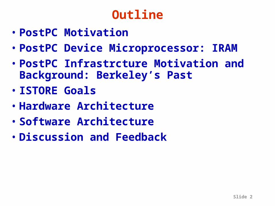
Outline• PostPC Motivation• PostPC Device Microprocessor: IRAM• PostPC Infrastrcture Motivation and
Background: Berkeley’s Past• ISTORE Goals • Hardware Architecture• Software Architecture• Discussion and Feedback

Slide 3
Motivation• Next generation fixes problems of last gen.• 1960s: batch processing + slow turnaround
Timesharing– 15-20 years of performance improvement, cost
reduction (minicomputers, semiconductor memory)
• 1980s: Time sharing + inconsistent response times Workstations/Personal Computers– 15-20 years of performance improvement, cost
reduction (microprocessors, DRAM memory, disk)
• 2000s: PCs + difficulty of use/high cost of ownership ???

Slide 4
Perspective on Post-PC Era• PostPC Era Divides built on two
technologies:1) Mobile Consumer Electronic Devices
– e.g., successor to PDA, Cell phone, wearable computers
2) Infrastructure to Support such Devices– e.g., successor to Big Fat Web Servers,
Databases

Slide 5
Intelligent PDA ( 2003?)
Pilot PDA+ gameboy, cell phone,
radio, timer, camera, TV remote, am/fm radio, garage door opener, ...
+ Wireless data (WWW)+ Speech, vision recog.
+ Voice output for conversations Speech control
+Vision to see, scan documents, read bar code, ...

Slide 6
New Architecture Directions
• “…media processing will become the dominant force in computer arch. & MPU design.”
• “... new media-rich applications... involve significant real-time processing of continuous media streams, & make heavy use of vectors of packed 8-, 16-, and 32-bit integer and Fl.Pt.”
• Needs include real-time response, continuous media data types, fine grain parallelism, coarse grain parallelism, memory BW– “How Multimedia Workloads Will Change Processor
Design”, Diefendorff & Dubey, IEEE Computer(9/97)
Slide 7
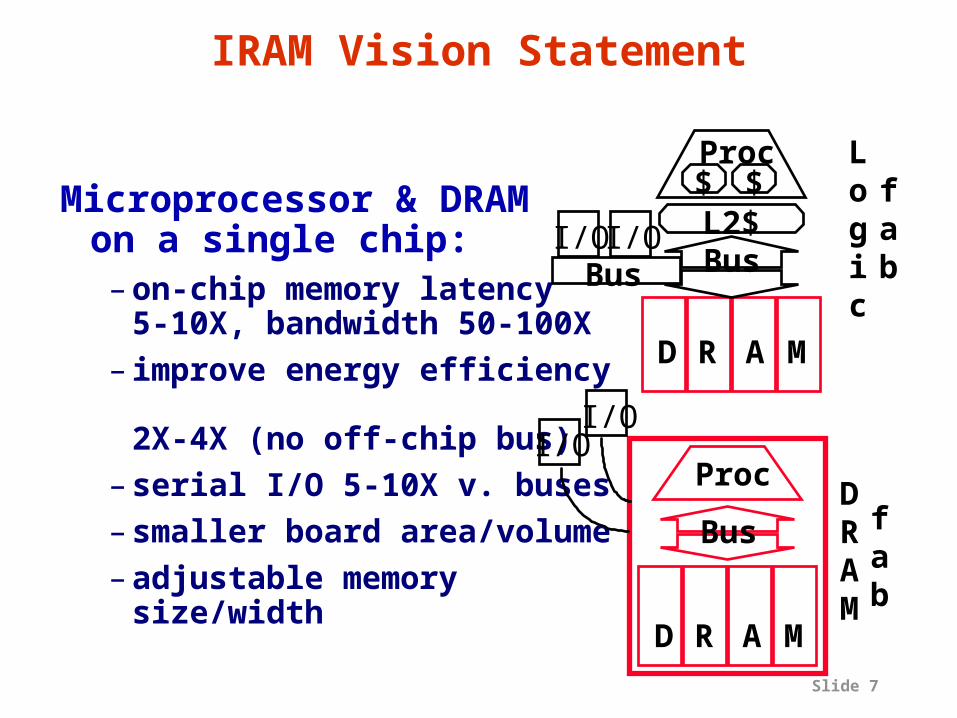
IRAM Vision Statement
Microprocessor & DRAM on a single chip:– on-chip memory latency
5-10X, bandwidth 50-100X– improve energy efficiency
2X-4X (no off-chip bus)– serial I/O 5-10X v. buses– smaller board
area/volume– adjustable memory
size/width
DRAM
fab
Proc
Bus
D R A M
$ $Proc
L2$
Logic
fabBus
D R A M
I/OI/O
I/OI/O
Bus

Slide 8
V-IRAM1: 0.25 µm, Fast Logic, 200 MHz
1.6 GFLOPS(64b)/6.4 GOPS(16b)/32MB
Memory Crossbar Switch
M
M
…
M
M
M
…
M
M
M
…
M
M
M
…
M
M
M
…
M
M
M
…
M
…
M
M
…
M
M
M
…
M
M
M
…
M
M
M
…
M
+
Vector Registers
x
÷
Load/Store
16K I cache 16K D cache
2-way Superscalar
VectorProcessor
4 x 64 4 x 64 4 x 64 4 x 64 4 x 64
4 x 64or
8 x 32or
16 x 16
4 x 644 x 64
QueueInstruction
I/OI/O
I/OI/O
SerialI/O

Slide 9
Outline• PostPC Motivation• PostPC Device Microprocessor: IRAM• PostPC Infrastrcture Motivation and
Background: Berkeley’s Past• ISTORE Goals • Hardware Architecture• Software Architecture• Discussion and Feedback

Slide 10
Ring-basedSwitch
CPU+$
Tentative VIRAM-1 Floorplan
I/O
0.18 µm DRAM32 MB in 16 banks x 256b, 128 subbanks
0.25 µm, 5 Metal Logic
≈ 200 MHz CPU, 8K I$, 8K D$
4 ≈ 200 MHz FP/int. vector units
die: ≈ 16 x16 mm xtors: ≈ 270M power: ≈2 Watts
4 Vector Pipes/Lanes
Memory (128 Mbits / 16 MBytes)
Memory (128 Mbits / 16 MBytes)

Slide 11
Background for ISTORE: RAID-I• RAID-I (1989)
– consisted of a Sun 4/280 workstation with 128 MB of DRAM, four dual-string SCSI controllers, 28 5.25-inch SCSI disks and specialized disk striping software

Slide 12
Background for ISTORE: RAID-II• RAID-II (1993)
– A network attached storage device. 2 outer racks contained 144 disks (3.5” IBM 320 MB SCSI) & power supplies. Center rack in 3 parts: top chassis holds VME disk controller boards, center chassis contains custom crossbar switch and HIPPI network (1Gb/s) interface boards; bottom chassis contains the Sun 4/280 workstation.

Slide 13
Background: Tertiary Disk• Tertiary Disk
(1997) – cluster of 20 PCs
hosting 364 3.5” IBM disks (8.4 GB) in 7 7’x19” racks, or 3 TB. The 200MHz, 96 MB P6 PCs run FreeBSD and a switched 100Mb/s Ethernet connects the hosts. Also 4 UPS units. – Hosts world’s largest art
database:72,000 images in cooperation with San Francisco Fine Arts Museum:Try www.thinker.org

Slide 14
Tertiary Disk HW Failure Experience
Reliability of hardware components (20 months)7 IBM SCSI disk failures (out of 364, or 2%)
6 IDE (internal) disk failures (out of 20, or 30%)
1 SCSI controller failure (out of 44, or 2%)
1 SCSI Cable (out of 39, or 3%)
1 Ethernet card failure (out of 20, or 5%)
1 Ethernet switch (out of 2, or 50%)
3 enclosure power supplies (out of 92, or 3%)
1 short power outage (covered by UPS)
Did not match expectations:SCSI disks more reliable than cables!

Slide 15
Saw 2 Error Messages per Day• SCSI Error Messages:
– Time Outs: Response: a BUS RESET command
– Parity: Cause of an aborted request
• Data Disk Error Messages:– Hardware Error: The command unsuccessfully
terminated due to a non-recoverable HW failure.
– Medium Error: The operation was unsuccessful due to a flaw in the medium (try reassigning sectors)
– Recovered Error: The last command completed with the help of some error recovery at the target
– Not Ready: The drive cannot be accessed

Slide 16
SCSI Time Outs+Recovered Errors (m0)
SCSI Bus 0

Slide 17
Zoom In: Disk Recovered Errors
0
246
81012
1416
10/16/98
12:28
10/16/98
12:43
10/16/98
12:57
10/16/98
13:12
10/16/98
13:26
10/16/98
13:40
10/16/98
13:55
10/16/98
14:09
10/16/98
14:24
SCSI Bus 0 Disks
Disk Recovered ErrorsSCSI Time Outs
SCSI Bus 0

Slide 18
Can we predict a disk failure?
•Yes, we can look for Recovered Error messages on 10-16-98:–There were 433 Recovered Error Messages
–These messages lasted for slightly over an hour between: 12:43 and 14:10
•On 11-24-98: Disk 5 on m0 was “fired”, i.e. it appeared to operator it was about to fail, so it was swapped
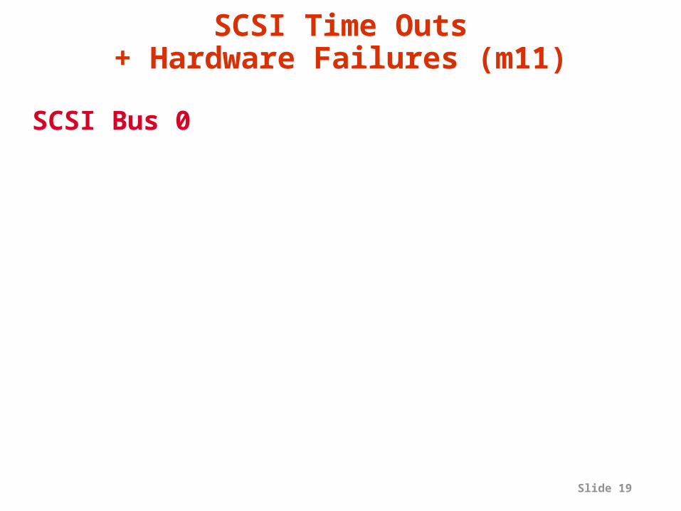
Slide 19
SCSI Time Outs+ Hardware Failures (m11)
SCSI Bus 0

Slide 20
Can we predict a disk failure?•Yes, look for Hardware Error
messages–These messages lasted for 8 days between:
»8-17-98 and 8-25-98
–On disk 9 there were:»1763 Hardware Error Messages, and»297 SCSI Timed Out Messages
•On 8-28-98: Disk 9 on SCSI Bus 0 of m11 was “fired”, i.e. appeared it was about to fail, so it was swapped
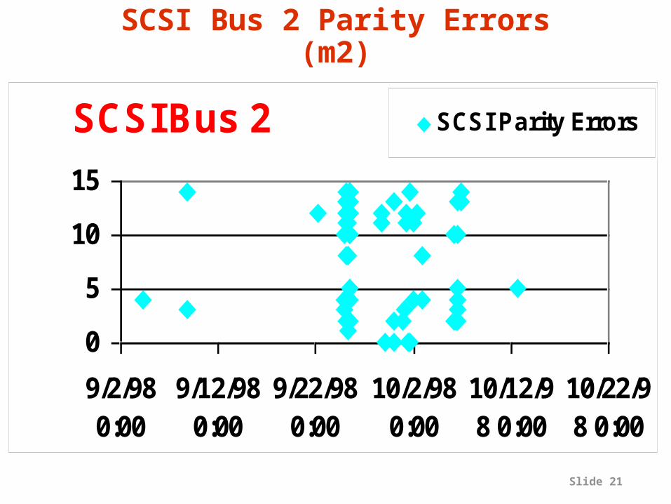
Slide 21
SCSI Bus 2
0
5
10
15
9/2/980:00
9/12/980:00
9/22/980:00
10/2/980:00
10/12/98 0:00
10/22/98 0:00
SCSI Bus 2 Disks
SCSI Parity Errors
SCSI Bus 2 Parity Errors (m2)

Slide 22
Can We Predict Other Kinds of Failures?
•Yes, the flurry of parity errors on m2 occurred between:– 1-1-98 and 2-3-98, as well as – 9-3-98 and 10-12-98
•On 11-24-98–m2 had a bad enclosure cables or connections defective
–The enclosure was then replaced

Slide 23
Lessons from Tertiary Disk Project
• Maintenance is hard on current systems– Hard to know what is going on, who is to
blame
• Everything can break– Its not what you expect in advance– Follow rule of no single point of failure
• Nothing fails fast– Eventually behaves bad enough that
operator fires poor performer, but it doesn’t quit
• Many failures may be predicted

Slide 24
Outline• PostPC Motivation• PostPC Device Microprocessor: IRAM• PostPC Infrastrcture Motivation and
Background: Berkeley’s Past• ISTORE Goals • Hardware Architecture• Software Architecture• Discussion and Feedback

Slide 25
Storage Priorities: Research v. Users
Current Research Priorities
1) Performance1’) Cost 3) Scalability4) Availability5) Maintainability
Current Server Customer
Priorities1) Availability2) Maintainability3) Scalability4) Performance5) Cost(From Sun marketing presentation, 2/99)

Slide 26
Intelligent Storage Project Goals• ISTORE: a hardware/software
architecture for building scaleable, self-maintaining storage– An introspective system: it monitors itself
and acts on its observations
• Self-maintenance: does not rely on administrators to configure, monitor, or tune system

Slide 27
Self-maintenance• Failure management
– devices must fail fast without interrupting service
– predict failures and initiate replacement
– failures immediate human intervention
• System upgrades and scaling– new hardware automatically incorporated
without interruption – new devices immediately improve
performance or repair failures
• Performance management– system must adapt to changes in workload or
access patterns

Slide 28
ISTORE-I Hardware
• ISTORE uses “intelligent” hardware
Intelligent Chassis: scaleable, redundant,
fast network +
UPSDevice
CPU, memory, NI
Intelligent Disk “Brick”: a disk, plus a fast embedded CPU, memory, and redundant network interfaces

Slide 29
ISTORE-I: Summer 99?• Intelligent disk
– Portable PC Hardware: Pentium II, DRAM– Low Profile SCSI Disk (9 to 18 GB)– 4 100-Mbit/s Ethernet links per Idisk– Placed inside Half-height canister– Monitor Processor/path to power off
components?
• Intelligent Chassis– 64 IDisks: 8 enclosures, 8 IDisks/enclosure
» 64 x 4 or 256 Ethernet ports
– 2 levels of Ethernet switches: 14 small, 2 large » Small: 20 100-Mbit/s + 2 1-Gbit; Large: 25 1-Gbit
– Enclosure sensing, UPS, redundant PS, fans, ...
Slide 30
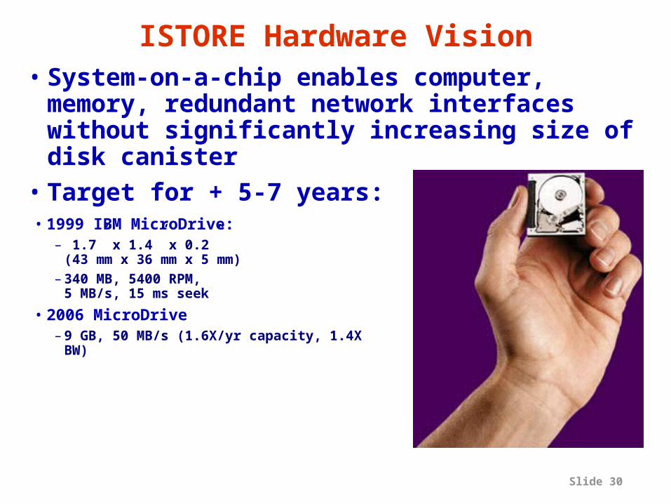
ISTORE Hardware Vision• System-on-a-chip enables computer,
memory, redundant network interfaces without significantly increasing size of disk canister
• Target for + 5-7 years:• 1999 IBM MicroDrive:
– 1.7” x 1.4” x 0.2” (43 mm x 36 mm x 5 mm)
– 340 MB, 5400 RPM, 5 MB/s, 15 ms seek
• 2006 MicroDrive– 9 GB, 50 MB/s (1.6X/yr capacity, 1.4X
BW)

Slide 31
2006 ISTORE• ISTORE node
– Add 20% pad to size for packaging, connectors– Then double thickness to add IRAM– 2.0” x 1.7” x 0.5”
• Crossbar switches growing by Moore’s Law– 2x/1.5 yrs 4X transistors/3yrs– Crossbars grow N2 2X switch/3yrs– 16 x 16 in 1999 64 x 64 in 2005
• ISTORE Rack (19” x 33” x 84”) – 1 tray 16 x 32 512 ISTORE nodes– 20 trays+switches+UPS 10,000 ISTORE
nodes(!)

Slide 32
Outline• PostPC Motivation• PostPC Device Microprocessor: IRAM• PostPC Infrastrcture Motivation and
Background: Berkeley’s Past• ISTORE Goals • Hardware Architecture• Software Architecture• Discussion and Feedback

Slide 33
Software Motivation• Data-intensive network-based services
are becoming the most important application for high-end computing
• But servers for them are too hard to manage!
• We need single-purpose, introspective storage appliances– single-purpose: customized for one application– introspective: self-monitoring and adaptive
» with respect to component failures, addition of new hardware resources, load imbalance, workload changes, ...
• But introspective systems are hard to build!

Slide 34
ISTORE Makes it Easy!• ISTORE = Introspective Storage
platform– Software: toolkit for defining and implementing
application-specific monitoring and adaptation» base layer supplies repository for monitoring
data, mechanisms for invoking reaction code» for common adaptation goals, appliance
designer’s policy statements guide automatic generation of adaptation algorithms
– Hardware: intelligent devices with integrated self-monitoring

Slide 35
Base Layer: Views and Triggers
• Monitoring data is stored in a dynamic system database– device status, access patterns, perf. stats, ...
• System supports views over the data ...– applications select and aggregate data of
interest– defined using SQL-like declarative language
• ... as well as application-defined triggers that specify interesting situations as predicates over these views– triggers invoke application-specific reaction
code when the predicate is satisfied– defined using SQL-like declarative language

Slide 36
From Policy Statements to Adaptation Algorithms
• For common adaptation goals, designer can write simple policy statements– runtime invariants expressed as integrity
constraints over data stored in the DB– system automatically generates appropriate
views, triggers, and adaptation code templates
– claim: doable for common adaptation mechanisms needed by data-intensive network services
» component failure, data hot-spots, integration of new hardware resources, ...

Slide 37
Example• Invariant: system must maintain 3
replicas of all data objects– view: disks’ health status– trigger: a disk’s health status changes to “dead”
» invoke adaptation code, supplying• identities of objects that were stored on dead disk•view of utilization of all disks in the system
– adaptation code template: lock object, perform byte copy to least utilized disk, unlock object, update index
– adaptation code can be customized to exploit application semantic information
» e.g. application-specific selection of new disk(s) to hold replicated objects, data layout on disk, locking policy

Slide 38
How Does the Hardware Help?• “Intelligent” hardware gathers monitoring
data– implements views and triggers by filtering and
reacting to data as it’s gathered
• Highly redundant, scalable, and customizable
IntelligentChassis:switching
andpower
IntelligentDevice Brick
Device
CPU, memory, NI

Slide 39
Conclusion and Status• ISTORE provides a hardware/software
architecture that allows appliance designers to build introspective storage appliances
• Based on – intelligent, self-monitoring hardware– a virtual database of system status and
statistics– a software toolkit that uses a domain-
specific declarative language to specify integrity constraints
• Still just a vision• Prototype being constructed

Slide 40
ISTORE Conclusion• Qualitative Change for every 10X
Quantitative Change; 100X?• Systems no longer “Binary”
(1 perfect, 0 broken)• Real systems never perfect, never
broken• Based on Probablility Theory, not Logic
Theory?• Look to Biology for useful models?

Slide 41
Interested in Participating?• Project just getting formed• Contact us if you’re interested:http://iram.cs.berkeley.edu/istoreemail: [email protected]
• Thanks for support: DARPA• Thanks for advice/inspiration:
Dave Anderson (Seagate), Greg Papadopolous (Sun), Mike Ziegler (HP)

Slide 42
Backup Slides

Slide 43
ISTORE Cluster?
• 8 -12 disks / enclosure
• 12 enclosures / rack= 96-144 disks/rack
Cluster of PCs?• 2 disks / PC• 10 PCs /rack
= 20 disks/rack• Reliability?• Ease of Repair?• System
Admin.?• Cost only plus?
Slide 44
ISTORE and IRAM• ISTORE relies on intelligent devices• IRAM is an easy way to add intelligence
to a device– embedded, low-power CPU meets size and
power constraints– integrated DRAM reduces chip count– fast network interface (serial lines) meets
connectivity needs
• Initial ISTORE prototype won’t use IRAM– will use collection of commodity
components that approximate IRAM functionality, not size/power

Slide 45
ISTORE-I Software Plan• Modify Database (e.g., Predator) to send
log to mirrored Idisk– Since 1 processor per disk, continuously replay
the log on mirrored system
• Insert faults in original Idisk to get fail over
• Add monitoring, maintenance, fault insertion
• Run **ix OS– By running Linix binaries, can get multiple OS
with same API: Linix, Free BSD Unix, ...– Increase genetic base of OS software to reduce
chances of simulatenous software bugs– Periodic reboot to “refresh” system

Slide 46
Benefits of ISTORE• Decentralized processing (shared-nothing)
– system can withstand partial failure
• Monitor their own “health,” test themselves, manage failures, collect application-specified performance data, and execute applications– fault insertion to test availability– provides the foundation for self-maintenance and
self-tuning
• Plug & play, hot-swappable bricks ease configuration, scaling– hardware maybe specialized by selecting an
collection of devices: DRAMs, WAN/LAN interfaces

Slide 47
Other (Potential) Benefits of ISTORE
• Scalability: add processing power, memory, network bandwidth as add disks
• Smaller footprint vs. traditional server/disk
• Less power– embedded processors vs. servers– spin down idle disks?
• For decision-support or web-service applications, potentially better performance than traditional servers

Slide 48
Related Work• ISTORE adds several recent research
efforts– Active Disks, NASD (UCSB, CMU)– Network service appliances (NetApp, Snap!,
Qube, ...)– High availability systems (Compaq/Tandem, ...)– Adaptive systems (HP AutoRAID, M/S
AutoAdmin, M/S Millennium)– Plug-and-play system construction (Jini, PC
Plug&Play, ...)