Embed Size (px)
Citation preview
Slide 1
5th LHC RADIATION WORKSHOP, CERN, 2005-11-29, Jochen Kuhnhenn, Fraunhofer INT
2005-11-29
Radiation tolerant fibres for LHC controls and communications
Jochen Kuhnhenn
Fraunhofer INTAppelsgarten 2D-53879 EuskirchenGermany

Slide 2
5th LHC RADIATION WORKSHOP, CERN, 2005-11-29, Jochen Kuhnhenn, Fraunhofer INT
2005-11-29
Outline
Introduction
Project overview: "Radiation tolerant fibres for LHC"
Results
Conclusions
Slide 3
5th LHC RADIATION WORKSHOP, CERN, 2005-11-29, Jochen Kuhnhenn, Fraunhofer INT
2005-11-29
Introduction
Introduction
Motivation
The Fraunhofer Institute at a glance
Radiation effects on optical fibres
Project overview
Results
Conclusions

Slide 4
5th LHC RADIATION WORKSHOP, CERN, 2005-11-29, Jochen Kuhnhenn, Fraunhofer INT
2005-11-29
Motivation
More than 1 500 km of optical cables needed for LHC
Control and communication
Beam instrumentation
Advantages of optical communication
Extreme noise immunity and ground potential independence
Lower attenuation (no repeater needed)
Higher flexibility (additional links on demand without tunnel access)
In LHC cleaning insertions IR3 and IR7 high radiation levels expected from day 1
First tests of installed fibres led to concerns if continuous transmission will be possible (Wijnands et al.: LHC Project Note 351, Presentation at 4th LHC radiation workshop)

Slide 5
5th LHC RADIATION WORKSHOP, CERN, 2005-11-29, Jochen Kuhnhenn, Fraunhofer INT
2005-11-29
The Fraunhofer INT
Experience of more than 30 years on effects of nuclear radiation on electronics and opto-electronics
The institute operates several irradiation facilities(Co-60, 14 MeV neutrons, flash X-Rays, access to 35 MeV protons)
Offering irradiation services to governmental, scientific, and industrial customers including planning and interpretation
Full range of measurement equipment for characterisation and analysis of radiation effects in electronics and opto-electronics
One focus: Radiation effects on optical fibres
Tested several 1 000 fibres of all types and manufacturers
Close contacts to fibre manufacturers and research institutions

Slide 6
5th LHC RADIATION WORKSHOP, CERN, 2005-11-29, Jochen Kuhnhenn, Fraunhofer INT
2005-11-29
Radiation effects on optical fibres
Ionising radiation changes every property of an optical fibre
Refractive index
Bandwidth
Mechanical properties (e.g., tensile strength)
Additional: Generation of luminescence light
These effects show up typically only at relatively high doses or dose rates
Most obvious and disturbing effect is the increase of attenuation

Slide 7
5th LHC RADIATION WORKSHOP, CERN, 2005-11-29, Jochen Kuhnhenn, Fraunhofer INT
2005-11-29
Parameter dependencies of RIA
Manufacturing influences
Fibre type (Single mode, graded index, step index)
Doping of core, doping of cladding (for SM fibres)
Preform manufacturer and used processes
Core material manufacturer
OH Content
Cladding core diameter ratio (CCDR)
Coating material
Drawing conditions
Operation conditions
Wavelength
Light power
Launch conditions
Environment
Total dose
Dose rate
Annealing periods
Temperature

Slide 8
5th LHC RADIATION WORKSHOP, CERN, 2005-11-29, Jochen Kuhnhenn, Fraunhofer INT
2005-11-29
"Radiation tolerant fibres for LHC": Project overview
Introduction
Project overview
Aims
Approach
Experimental details
Results
Conclusions

Slide 9
5th LHC RADIATION WORKSHOP, CERN, 2005-11-29, Jochen Kuhnhenn, Fraunhofer INT
2005-11-29
Project aims
Verification of previous irradiation tests of currently installed optical fibres by Draka
Full characterisation of radiation effects in used Ge-doped Draka fibre
Identification of optical fibres with better radiation resistance
Modelling of radiation induced loss at different dose rates

Slide 10
5th LHC RADIATION WORKSHOP, CERN, 2005-11-29, Jochen Kuhnhenn, Fraunhofer INT
2005-11-29
Project steps
Acquisition of possible alternative optical fibres
Screening test of all samples under identical conditions
Fixed dose, dose rate, temperature, light power, wavelength
Detailed testing of current Draka fibre and best two candidates
Variation of dose rate & dose, wavelength, light power
Accelerated simulation of LHC radiation environment
Slide 11
5th LHC RADIATION WORKSHOP, CERN, 2005-11-29, Jochen Kuhnhenn, Fraunhofer INT
2005-11-29
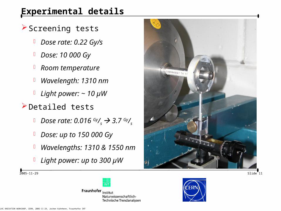
Experimental details
Screening tests
Dose rate: 0.22 Gy/s
Dose: 10 000 Gy
Room temperature
Wavelength: 1310 nm
Light power: ~ 10 µW
Detailed tests
Dose rate: 0.016 Gy/s 3.7 Gy/s
Dose: up to 150 000 Gy
Wavelengths: 1310 & 1550 nm
Light power: up to 300 µW
Slide 12
5th LHC RADIATION WORKSHOP, CERN, 2005-11-29, Jochen Kuhnhenn, Fraunhofer INT
2005-11-29
Results
Introduction
Project overview
Results
Identification of alternative products
Screening tests of candidates
Detailed testing of now used fibre and best candidates
Modelling of dose rate dependence
Conclusions

Slide 13
5th LHC RADIATION WORKSHOP, CERN, 2005-11-29, Jochen Kuhnhenn, Fraunhofer INT
2005-11-29
Identification of other products
Fraunhofer INT contacted 10 manufacturers known for radiation resistant optical fibres
Of those 6 provided samples
• Draka developed new fibre: "Draka New"
• Heraeus
• Fujikura
• Corning
• Manufacturer X
• Manufacturer Y
Additional sample of current Ge-doped fibre "Draka #445755"

Slide 14
5th LHC RADIATION WORKSHOP, CERN, 2005-11-29, Jochen Kuhnhenn, Fraunhofer INT
2005-11-29
Results of candidate screening test
Logarithmic scale
1 10 100 1000 10000
1
10
Ind
uce
d L
oss
[d
B/k
m]
Dose [Gy(SiO2)]
X
Fu jik ura
Heraeu s
Drak a 4457 55
Drak a N ew
Y
Corn ing
=1 31 0 n m , D =1 04 G y , D =0 .2 2 5 G y /s,
T =28 °C , l=10 0 m , P =1 0/4 0 µ W
0 2000 4000 6000 8000 10000
0
5
10
15
20
25
30
35
40
Ind
uce
d L
oss
[d
B/k
m]
Dose [Gy(SiO2)]
X
Fu jik ura
Heraeu s
Drak a 4457 55
Drak a N ew
Y
Corn ing
=1 31 0 n m , D=1 04 G y , D=0 .2 2 5 G y /s,
T =28 °C , l=10 0 m , P =1 0/4 0 µW
Linear scale

Slide 15
5th LHC RADIATION WORKSHOP, CERN, 2005-11-29, Jochen Kuhnhenn, Fraunhofer INT
2005-11-29
Detailed tests of Draka #445755: Wavelength dependence
0 1000 2000 3000 4000 5000 6000 7000 8000 9000 10000
0
5
10
15
20
25
Ind
uc
ed
Lo
ss
[dB
/km
]
Dose [Gy(SiO2)]
Drak a 44 5755
Drak a 44 5755 (15 50 nm )
=1 3 10 /15 50 nm , D =104 G y, D= 0.2 25 G y/s ,
T =2 8°C , l=1 00 m , P=1 0 µW

Slide 16
5th LHC RADIATION WORKSHOP, CERN, 2005-11-29, Jochen Kuhnhenn, Fraunhofer INT
2005-11-29
Detailed tests of Draka #445755: Dose rate dependence
0.1 1 10 100 1000 10000 100000
0.1
1
10
100
Ind
uc
ed
Lo
ss
[dB
/km
]
Dose [Gy(SiO2)]
Drak a 44 5755
Drak a 44 5755 (3.7 Gy /s)
Drak a 44 5755 (1.6 Gy /s)
Drak a 44 5755 (0.02 G y/s)
=1 3 10 nm , D =103, 1 0
4, 10
5 G y,
T =2 8°C , l=1 00 m , P=1 0 µW
Slide 17
5th LHC RADIATION WORKSHOP, CERN, 2005-11-29, Jochen Kuhnhenn, Fraunhofer INT
2005-11-29
0.1 1 10 100 1000 10000 100000
0.1
1
10
100
Ind
uc
ed
Lo
ss
[dB
/km
]
Dose [Gy(SiO2)]
0.02 Gy/s
0.22 Gy/s
3.7 Gy/s
1.6 Gy/s
0.1 1 10 100 1000 10000 100000
0.1
1
10
100
Ind
uc
ed
Lo
ss
[dB
/km
]
Dose [Gy(SiO2)]
0.02 Gy/s
0.22 Gy/s
3.7 Gy/s
1.6 Gy/s
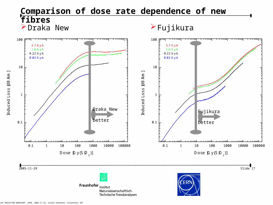
Comparison of dose rate dependence of new fibres
Draka New Fujikura
0.1 1 10 100 1000 10000 100000
0.1
1
10
100
Ind
uc
ed
Lo
ss
[dB
/km
]
Dose [Gy(SiO2)]
0.02 Gy/s
0.22 Gy/s
3.7 Gy/s1.6 Gy/s
0.1 1 10 100 1000 10000 100000
0.1
1
10
100
Ind
uc
ed
Lo
ss
[dB
/km
]
Dose [Gy(SiO2)]
0.02 Gy/s
0.22 Gy/s
3.7 Gy/s1.6 Gy/s
Draka New
better
Fujikura
better

Slide 18
5th LHC RADIATION WORKSHOP, CERN, 2005-11-29, Jochen Kuhnhenn, Fraunhofer INT
2005-11-29
Radiation induced loss of used and new fibres: Summary
Results for currently installed Ge-doped fibre by Draka
It is one of the best tested fibres of this type
1310 nm has advantages for doses higher than 6000 Gy
Increased light power does not improve radiation resistance (not shown in slides)
Two new candidates characterised with focus on dose rate dependence
Both candidates show better radiation tolerance for higher doses
• Draka New better at least by a factor of 2 for highest doses
• Fujikura better above 10 Gy with best performance (by a factor of 10) between 100 and 1000 Gy

Slide 19
5th LHC RADIATION WORKSHOP, CERN, 2005-11-29, Jochen Kuhnhenn, Fraunhofer INT
2005-11-29
LHC operation conditions assumed for loss modelling
LHC Project Note 375
One LHC year: 140 days of physics
Assumptions
• “Nominal” physics
• Fill length + Turn around: 8 + 3 hours
• 2.3×10¹⁶ total beam loss per year in IR7
• Dose in fibres ~ 10 000 Gy per 1016 protons(private communication: Wijnands, Kurochkin)
Expected radiation environment for optical fibres in IR7
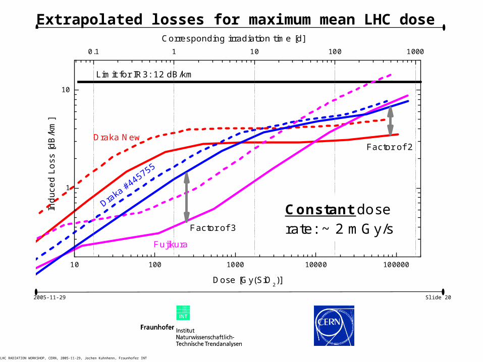
Maximum averaged dose per year: ~ 23 000 Gy
Maximum mean dose rate: 2 mGy/s
Peak dose rates expected to be much higher
Slide 20
5th LHC RADIATION WORKSHOP, CERN, 2005-11-29, Jochen Kuhnhenn, Fraunhofer INT
2005-11-29
Extrapolated losses for maximum mean LHC dose rate
10 100 1000 10000 100000
1
10
0.1 1 10 100 1000
Ind
uc
ed
Lo
ss
[dB
/km
]
Dose [Gy(SiO2)]
Fujikura
Draka #445755
Draka New
Constant doserate: ~ 2 mGy/sFactor of 3
Factor of 2
Limit for IR3: 12 dB/km
Corresponding irradiation time [d]

Slide 21
5th LHC RADIATION WORKSHOP, CERN, 2005-11-29, Jochen Kuhnhenn, Fraunhofer INT
2005-11-29
Accelerated simulation of LHC conditions
Acceleration by factor 10 for 20+10 operation:
Irradiation for 2 hours at ~ 20 mG/s
Annealing for 1 hour
Repeating 10 times
Same dose per cycle (~ 150 Gy) as expected for LHC
Simulates nearly two weeks of LHC operation
Comparison of cyclic irradiation with results of continuous irradiation at corresponding mean dose rate

Slide 22
5th LHC RADIATION WORKSHOP, CERN, 2005-11-29, Jochen Kuhnhenn, Fraunhofer INT
2005-11-29
Cyclic irradiation compared with continuous irradiation
1 10 100 1000
0.1
1
Ind
uc
ed
Lo
ss
[d
B/k
m]
Dose [Gy]
Continuous irradiation:Dose rate 16 mG y/s
Cyclic irradiation:Dose rate 24 mGy/s
Duty cycle 2+1 hoursAverage dose rate 16 mGy/s
Fujikura

Slide 23
5th LHC RADIATION WORKSHOP, CERN, 2005-11-29, Jochen Kuhnhenn, Fraunhofer INT
2005-11-29
Cyclic irradiation compared with continuous irradiation
10 100 10001
2
3
4
5
6
7
8
9
Draka New
Continuous irradiation:Dose rate 16 mGy/s
Cyclic irradiation:Dose rate 24 mGy/sDuty cycle 2+1 hoursAverage dose rate 16 mGy/s
Ind
uce
d L
oss
[d
B/k
m]
Dose [Gy]

Slide 24
5th LHC RADIATION WORKSHOP, CERN, 2005-11-29, Jochen Kuhnhenn, Fraunhofer INT
2005-11-29
Conclusions
Introduction
Project overview
Results
Conclusions

Slide 25
5th LHC RADIATION WORKSHOP, CERN, 2005-11-29, Jochen Kuhnhenn, Fraunhofer INT
2005-11-29
Conclusions
Currently installed Ge-doped Draka fibre can be operated for extended time(If average mean dose rate scaling is appropriate)
Both new candidates show better radiation tolerance(Extend depending on dose range)
Cyclic irradiations with annealing periods do not lead to a attenuation increase as the corresponding continuous irradiation
Better understanding of realistic conditions at LHC needs time-dependent dose rate data and further investigations

Slide 26
5th LHC RADIATION WORKSHOP, CERN, 2005-11-29, Jochen Kuhnhenn, Fraunhofer INT
2005-11-29
Thank you very much for your attention
I’m looking forward to your questions …
Contact:Dr. Jochen Kuhnhenn
Fraunhofer INTAppelgarten 2D-53879 EurkichenGermany
Tel.: +49(2251)18200
Fax: +49(2251)18378
Email: [email protected]