Embed Size (px)
Citation preview
AOPD3AA2
UL File Number: E215245
SLCS* and SLCS*/35 safety
light curtains
Original Instructions

With regard to the supply of products, the current issue of the following document is applicable: The General Terms of Delivery for Products and Services of the Electrical Industry, published by the Central Association of the Electrical Industry (Zentralverband Elektrotechnik und Elektroindustrie (ZVEI) e.V.) in its most recent version as well as the supplementary clause: "Expanded reservation of proprietor-ship"
Worldwide
Pepperl+Fuchs Group
Lilienthalstr. 200
68307 Mannheim
Germany
Phone: +49 621 776 - 0
E-mail: [email protected]
North American Headquarters
Pepperl+Fuchs Inc.
1600 Enterprise Parkway
Twinsburg, Ohio 44087
USA
Phone: +1 330 425-3555
E-mail: [email protected]
Asia Headquarters
Pepperl+Fuchs Pte. Ltd.
P+F Building
18 Ayer Rajah Crescent
Singapore 139942
Phone: +65 6779-9091
E-mail: [email protected]
https://www.pepperl-fuchs.com
3
SLCS* and SLCS*/35 safety light curtainsContents
271
694
20
20-0
2
1 Introduction................................................................................................................ 5
1.1 Content of this Document............................................................................. 5
1.2 Symbols Used ................................................................................................ 5
2 Safety information ..................................................................................................... 7
3 Product Description .................................................................................................. 9
3.1 Use and Application ...................................................................................... 9
3.2 Indicators and Operating Controls ............................................................ 10
3.3 Interfaces and Connections ....................................................................... 11
3.4 Scope of Delivery......................................................................................... 12
4 Installation................................................................................................................ 13
4.1 Planning and preparation ........................................................................... 13
4.2 Mounting....................................................................................................... 16
4.3 Reflection...................................................................................................... 18
4.4 Connection and Operating Mode Setting.................................................. 19
4.4.1 Signal outputs on the receiver unit ................................................... 204.4.2 Signal Inputs on the Transmitter Unit................................................ 204.4.3 Signal inputs on the receiver unit ..................................................... 214.4.4 Typical circuits.................................................................................. 23
5 Commissioning........................................................................................................ 24
5.1 Functional Testing........................................................................................ 24
5.2 Multiple Positions ........................................................................................ 24
6 Maintenance and Repair ......................................................................................... 27
6.1 Maintenance................................................................................................. 27
6.2 Periodic Checks ........................................................................................... 27
6.3 Repairs.......................................................................................................... 28
7 Troubleshooting....................................................................................................... 29
7.1 Troubleshooting........................................................................................... 29
8 Appendix .................................................................................................................. 31
8.1 Technical Data.............................................................................................. 31
8.1.1 Functional Safety Standards and Parameters .................................. 33
8.2 Safety Light Curtains - Profile Lengths and Weight ................................. 35

SLCS* and SLCS*/35 safety light curtainsContents
4
271
694
20
20-0
2
8.3 Dimension drawings....................................................................................36
8.4 Type code......................................................................................................37
8.5 Application Checklist ..................................................................................41
8.6 Accessories..................................................................................................43
8.6.1 Mounting Aid OMH-SLCT-01............................................................ 468.6.2 Mounting Aid OMH-SLCT-02............................................................ 478.6.3 Mounting brackets OMH-SLCT-03 and OMH-SLCT-04 .................... 478.6.4 Mounting Aid OMH-SLCT-05........................................................... 478.6.5 OMH-SLCT-12 -500 Muting arm with round rod ............................... 488.6.6 OMH-07-01 Mounting bracket for circular profiles ............................ 488.6.7 OMH-SLCT-100-xxxx Mounting profile for floor mounting ................ 488.6.8 OMH-SLCT-110-xxxx Mounting profile with decorative cover (front) 488.6.9 OMH-SLCT-120-xxx Lateral protective covers for mounting profile .. 488.6.10 OMH-SLCT-200 Floor mount for soil column/mounting profile.......... 498.6.11 SLCT-M-01-xxxx inclined mirror for 90° deflection ................................ 49
8.6.12 Alignment aid ................................................................................... 498.6.13 Test rod ............................................................................................ 508.6.14 Connection Cables........................................................................... 50
SLCS* and SLCS*/35 safety light curtainsIntroduction
271
694
20
20-0
2
5
1 Introduction
1.1 Content of this Document
This document contains safety-relevant information for usage of the device. You need this infor-mation to use your product throughout the applicable stages of the product life cycle. These can include the following:
■ Product identification
■ Delivery, transport, and storage
■ Mounting and installation
■ Commissioning and operation
■ Maintenance and repair
■ Troubleshooting
■ Dismounting
■ Disposal
The documentation consists of the following parts:
■ Original instructions (present document)
■ EU declaration of conformity
■ Datasheet
For more information about Pepperl+Fuchs products with functional safety, see www.pepperl-fuchs.com/sil.
1.2 Symbols Used
This document contains symbols for the identification of warning messages and of informative messages.
Warning Messages
You will find warning messages, whenever dangers may arise from your actions. It is mandatory that you observe these warning messages for your personal safety and in order to avoid prop-erty damage.
Depending on the risk level, the warning messages are displayed in descending order as fol-lows:
Note
For full information on the product, refer to the further documentation on the Internet at www.pepperl-fuchs.com.
Danger!
This symbol indicates an imminent danger.
Non-observance will result in personal injury or death.
Warning!
This symbol indicates a possible fault or danger.
Non-observance may cause personal injury or serious property damage.

271
694
20
20-0
2
6
SLCS* and SLCS*/35 safety light curtainsIntroduction
Informative Symbols
Action
This symbol indicates a paragraph with instructions. You are prompted to perform an action or a sequence of actions.
Caution!
This symbol indicates a possible fault.
Non-observance could interrupt the device and any connected systems and plants, or result in their complete failure.
Note
This symbol brings important information to your attention.

SLCS* and SLCS*/35 safety light curtainsSafety information
271
694
20
20-0
2
7
2 Safety information
Read the following information carefully and follow this information when working with the device. Failure to observe the safety information and warning messages in this documentation can lead to malfunctions of the safety devices of the machines or plants in which they are fitted.
This can result in serious personal injury or death.
Target Group, Personnel
Responsibility for planning, assembly, commissioning, operation, maintenance, and dismount-ing lies with the plant operator.
The personnel must be appropriately trained and qualified in order to carry out mounting, installation, commissioning, operation, maintenance, and dismounting of the device. The trained and qualified personnel must have read and understood the instruction manual.
Prior to using the product make yourself familiar with it. Read the instruction manual carefully.
Reference to Further Documentation
Observe laws, standards, and directives applicable to the intended use and the operating loca-tion.
If you use the device in safety-related applications, observe the requirements for functional safety. You can find these requirements in the functional safety documentation under www.pep-perl-fuchs.com.
Intended Use
The device is only approved for appropriate and intended use. Ignoring these instructions will void any warranty and absolve the manufacturer from any liability.
If you use the device in safety-related applications, observe the information for safety function and safe state.
The safety light curtain may only be used in accordance with its intended purpose as noncon-tact electro-sensitive protective equipment (ESPE) for securing sources of danger and hazard-ous areas on machines and plants.
Ensure that this device is used only in accordance with the technical specification described in these instructions. The device must not be used outdoors or in an explosion-hazardous area.
Plant design
Before selecting and using the product, an assessment must be made to determine whether this product is suitable for the intended application. Pepperl+Fuchs has no influence on the selection and use of this product. The warranty therefore only covers the consistent quality of the product.
Mounting and installation
If you install the device in safety-related applications, observe the requirements for functional safety.
Operation, maintenance, repair
If you are operating the device in applications related to safety, note the requirements for func-tional safety.
Do not remove the nameplate.
Do not remove the warning markings.
Record the results of inspections and maintenance carefully.
Do not repair, modify, or manipulate the device.
If there is a defect, always replace the device with an original device.
Only use accessories specified by the manufacturer.

271
694
20
20-0
2
8
SLCS* and SLCS*/35 safety light curtainsSafety information
Delivery, Transport, Disposal
Keep the original packaging. Always store and transport the device in the original packaging.
The device, built-in components, packaging, and any batteries contained within must be dis-posed in compliance with the applicable laws and guidelines of the respective country.

SLCS* and SLCS*/35 safety light curtainsProduct Description
271
694
20
20-0
2
9
3 Product Description
3.1 Use and Application
Product description
The SLCS safety light curtain is noncontact electro-sensitive protective equipment (ESPE) for securing sources of danger and hazardous areas.
The SLCS consists of a transmitter and a receiver unit. The protection field is formed by infra-red light beams sent from the transmitter to the receiver. The offset between the individual light beams determines the minimum obstruction size (14, 30, 60, or 90 mm) that can be reliably detected in the entire protection field range.
The transmitter unit contains a certain number of transmitter diodes that emit protective beams. The number of transmitter diodes is determined by the protection field height and size of the obstacle. The function mode A/B enables the use of 2 adjacent safety light curtains.
The receiver unit detects the transmission beams, controls the two protective OSSD (Output Signal Switching Devices) safety outputs and carries out tests to ensure safety.
In addition to the displays behind the front panel of the receiver unit, there is also a PNP output, which indicates operational readiness, a dirty lens, or fault states. If an internal fault occurs in the receiver unit, this output switches on and off at a frequency of 5 Hz. If an external fault occurs, this output switches on and off at a frequency of 1 Hz. If the received signal is too weak (e.g., due to a dirty lens), the output switches on and off at a frequency of 2.5 Hz.
The test input on the transmitter initiates a test sequence. Activate the input by applying 24 VDC to the input for a defined time span.
The relay monitor (RM) and restart (RI) inputs allow monitoring of the switching elements con-nected externally to the OSSDs and activation of the startup/restart interlock function.
Figure 3.1 Schematic diagram of a detection device
Product Features
■ Type 4 ESPE in accordance with IEC/EN 61496-1
■ Self-testing
■ Obstacle size, depending on type, 14 mm, 30 mm, 60 mm, 90 mm
Transmitter unit
24 V supply 24 V supply
OSSDs
Status / Select RI-RM
Restart Interlock (RI)
Relay Monitor (RM)
Beam Code A/B
Protection
Receiver unit
Test
Beam Code A/B

271
694
20
20-0
2
10
SLCS* and SLCS*/35 safety light curtainsProduct Description
■ Protection field heights up to 1200 mm (SCLS14)
■ Protection field heights up to 2400 mm (SLCS30, SLCS60, SLCS90)
■ Protection field grid, 100 mm (SLCS14, SLCS30)
■ Protection field grid, 300 mm (SLCS60, SLCS90)
■ Selectable startup/restart interlock
■ Selectable relay monitor
■ Simple layout
■ Two OSSDs
Further information about the product
The following information about the SLCS series is provided in the appendix at the end of this document:
Technical data: see chapter 8.1.
Available profile lengths/dimensions: see chapter 8.2.
Dimensional drawings: see chapter 8.3.
Product characteristics by type code: see chapter 8.4.
Available accessories: see chapter 8.6.
3.2 Indicators and Operating Controls
The transmitter has two LEDs to display its operating status.
The receiver has five LEDs to display its operating status.
Figure 3.2 Displays on the transmitter and receiver units
No. Designation LED Color Meaning
1 Power LED Green Transmitter and receiver units operating
2 A/B mode, status Yellow Indicator flashing at 1 Hz: testing time exceededor A/B mode input level change
Indicator flashing at 5 Hz: internal fault
3 OSSD OFF Red OSSDs switched off
4 OSSD ON Green OSSDs switched on
1 Power green
2 Mode A/B, Status yellow
3 OSSD OFF red
4 OSSD ON green
5 Restart/Status yellow
6 Mode A/B yellow
Transmitter Receiver
1
2
3
5
4
6
1

SLCS* and SLCS*/35 safety light curtainsProduct Description
271
694
20
20-0
2
11
3.3 Interfaces and Connections
The electrical connections of the safety light curtain are made using M12 plug-in connectors. The transmitter has a 4-pin connector and the receiver an 8-pin plug-in connector.
Connect the power supply and, depending on the application, the test signal to the transmitter unit. The mode can also be selected via the A/B mode input.
Connect the power supply, the fail-safe outputs (OSSD), the status/select output and the inputs for the startup enable, relay monitor and A/B mode to the receiver unit.
The housing profile is connected internally with approx. 2.3 MOhm// 33 nF each at +24 V and 0 V. Internal varistors limit any surges that occur at approx. 85 V. A separate grounding or con-nection between the housing and functional ground is not required.
Transmitter
Figure 3.3 Pin assignment transmitter unit
Receiver
Figure 3.4 Pin assignment receiver unit
5 Restart/status Yellow On: protection field free: system ready to start Indicator flashing at 1 Hz: external fault Indicator flashing at 2.5 Hz: insufficient func-tional reserve Indicator flashing at 5 Hz: internal fault
6 Mode A/B Yellow Off: mode A On: mode B
No. Designation LED Color Meaning
1 24 V DC
2 Mode A/B
3 0 V DC
4 Test
1 Restart Interlock (RI)
2 24 V DC
3 Relaismonitor (RM)
4 Status / Select RI-RM
5 OSSD 1
6 OSSD 2
7 0 V DC
8 Mode A/B
1
3
42
1
4
6
78
53
2

271
694
20
20-0
2
12
SLCS* and SLCS*/35 safety light curtainsProduct Description
3.4 Scope of Delivery
The scope of delivery includes:
Scope of delivery: transmitter
■ Transmitter
Scope of delivery: receiver
■ Receiver
■ I/O Manual
■ Test rod
Bracket and cable are not included in the scope of delivery. Visit www.pepperl-fuchs.com for a selection of compatible fixing brackets and recommended cables.
0 V
24 V
OSSD 1/2

SLCS* and SLCS*/35 safety light curtainsInstallation
271
694
20
20-0
2
13
4 Installation
4.1 Planning and preparation
Safety distance
A minimum distance must be maintained between the protection field and the hazardous area to ensure potentially dangerous movements are brought to a stop before contact with a person is possible.
Figure 4.1 Minimum distance between protection field and hazardous area
This distance is calculated from the lag time of the machine, the response time of the safety system, and the speed of movement of the person entering the hazardous area (ISO/EN 13855).
To comply with the necessary distances in the event that the protection field spreads, please refer to Table 1 of ISO/EN 13855 to check the minimum distance for a vertically positioned pro-tection field. If you read the value 0 from the table, you can determine the minimum distance with the following formula: S = K x T + C
Where, for a protection field aligned vertically to the hazardous area:
Warning!
Danger to life due to ineffective protective equipment
Improper or incorrect alignment, fixing, and connection to machine control can impair the effec-tiveness of the protective function.
■ Note the applicable standards, guidelines, and legal regulations for the equipment of machine and plants with protective equipment.
■ Position the protective equipment to prevent persons from being able to reach or walk behind it, climb over or under, or otherwise bypass the equipment in any way.
■ Use appropriate safety distances to take into account the response times and lag times of the components in the safety chain.
■ Secure the protective equipment against manipulation or deliberate deactivation.
S Minimum safety distance in mm, i.e. the distance between hazardous area and pro-tection field
K Constant in mm/s for the speed of approach, based on the detection capacity of the sensor
T Total response time of the protective device in s (T = t1 +t2)
Danger zone
Minimum interval S
Sending unit
Protective field
Receiving unit
271
694
20
20-0
2
14
SLCS* and SLCS*/35 safety light curtainsInstallation
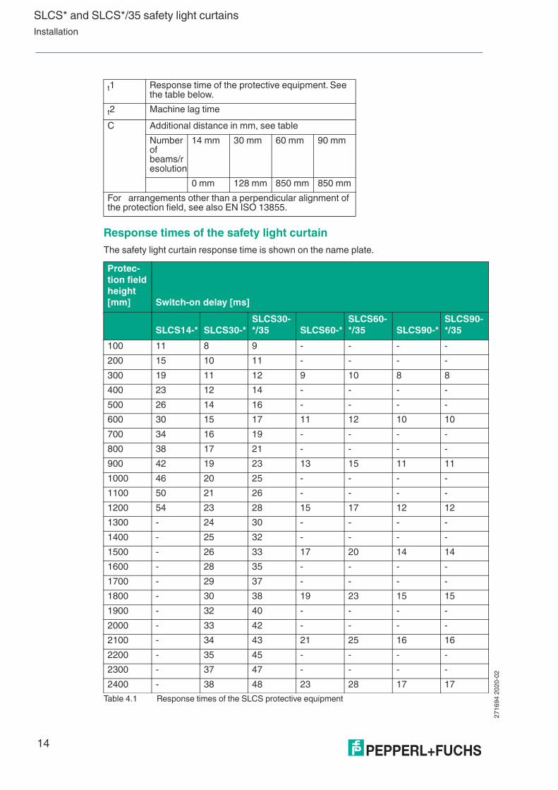
Response times of the safety light curtain
The safety light curtain response time is shown on the name plate.
t1 Response time of the protective equipment. See the table below.
t2 Machine lag time
C Additional distance in mm, see table
Number of beams/resolution
14 mm 30 mm 60 mm 90 mm
0 mm 128 mm 850 mm 850 mm
For arrangements other than a perpendicular alignment of the protection field, see also EN ISO 13855.
Protec-
tion field
height
[mm] Switch-on delay [ms]
SLCS14-* SLCS30-*
SLCS30-
*/35 SLCS60-*
SLCS60-
*/35 SLCS90-*
SLCS90-
*/35
100 11 8 9 - - - -
200 15 10 11 - - - -
300 19 11 12 9 10 8 8
400 23 12 14 - - - -
500 26 14 16 - - - -
600 30 15 17 11 12 10 10
700 34 16 19 - - - -
800 38 17 21 - - - -
900 42 19 23 13 15 11 11
1000 46 20 25 - - - -
1100 50 21 26 - - - -
1200 54 23 28 15 17 12 12
1300 - 24 30 - - - -
1400 - 25 32 - - - -
1500 - 26 33 17 20 14 14
1600 - 28 35 - - - -
1700 - 29 37 - - - -
1800 - 30 38 19 23 15 15
1900 - 32 40 - - - -
2000 - 33 42 - - - -
2100 - 34 43 21 25 16 16
2200 - 35 45 - - - -
2300 - 37 47 - - - -
2400 - 38 48 23 28 17 17
Table 4.1 Response times of the SLCS protective equipment

SLCS* and SLCS*/35 safety light curtainsInstallation
271
694
20
20-0
2
15
The switch-on time after beam interruption without a restart function is between 80 ms ... 200 ms. The switch-on time depends on the number of protective beams.
Notes on setting up safety light curtains
The protective equipment must be arranged in such a manner that it is impossible to reach over, reach under, or walk behind the protection field. If the distance from the safety device is too great, additional safety equipment must be put in place (see illustration below).
Reaching over
The user must not be able to reach over the protection field and into the hazardous area (A: protection field, B: mechanical protection).
Walking behind
The machine operator must not be able to walk between the light curtain and into the hazard-ous area (A: protection field, B: mechanical protection).

271
694
20
20-0
2
16
SLCS* and SLCS*/35 safety light curtainsInstallation
4.2 Mounting
Various mounting materials for mounting on machines or in the field are available for securing the safety light curtain. See chapter 8.6.
If you are planning to mount a safety light curtain with an increased detection range, we recom-mend that you use assembly profiles for floor mounting from our range of accessories. See chapter 8.6.7.
Mounting
1. Align the transmitter and receiver so that they are parallel with one another with both units at the same height.
2. Align the transmitters and receivers parallel with one another.
3. The stability alarm indicator helps with correct alignment.
When installing the safety light curtain in a source of danger, a minimum distance must be maintained between the protection field and the hazardous zone. This distance will guarantee that movements that pose a danger to a person can be brought to a stop before that person comes in contact with the source of danger.
The distance is calculated from the lag time of the machine, the response time of the safety light curtain, and the speed of movement of the person entering the hazardous area (EN ISO/EB 13855, ISO/EN 13857).
Vertical approach
Figure 4.2 Explanation of the safety distance in a vertical arrangement of the protective field
Warning!
Danger to life due to ineffective protective equipment
Improper or incorrect alignment, fixing, and connection to machine control can impair the effec-tiveness of the protective function.
■ Check the positioning of the protective equipment and ensure that it is not possible for persons to reach or walk behind it, climb over, under or otherwise bypass the protective equipment.
■ Check the safety distances and the lag times of the components in the safety chain.
■ Check that the protective equipment cannot be easily manipulated or disabled.
Distance S
Protective field
Danger
zone
SLCS* and SLCS*/35 safety light curtainsInstallation
271
694
20
20-0
2
17
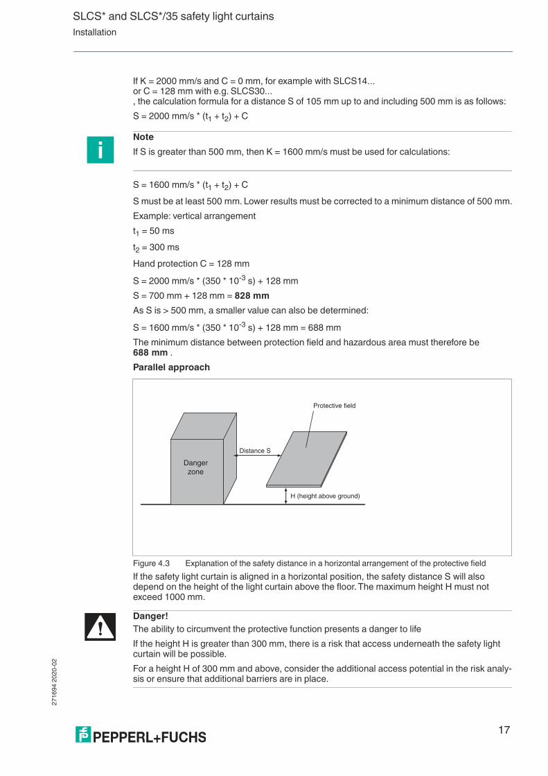
If K = 2000 mm/s and C = 0 mm, for example with SLCS14... or C = 128 mm with e.g. SLCS30... , the calculation formula for a distance S of 105 mm up to and including 500 mm is as follows:
S = 2000 mm/s * (t1 + t2) + C
S = 1600 mm/s * (t1 + t2) + C
S must be at least 500 mm. Lower results must be corrected to a minimum distance of 500 mm.
Example: vertical arrangement
t1 = 50 ms
t2 = 300 ms
Hand protection C = 128 mm
S = 2000 mm/s * (350 * 10-3 s) + 128 mm
S = 700 mm + 128 mm = 828 mm
As S is > 500 mm, a smaller value can also be determined:
S = 1600 mm/s * (350 * 10-3 s) + 128 mm = 688 mm
The minimum distance between protection field and hazardous area must therefore be 688 mm .
Parallel approach
Figure 4.3 Explanation of the safety distance in a horizontal arrangement of the protective field
If the safety light curtain is aligned in a horizontal position, the safety distance S will also depend on the height of the light curtain above the floor. The maximum height H must not exceed 1000 mm.
Note
If S is greater than 500 mm, then K = 1600 mm/s must be used for calculations:
Distance S
H (height above ground)
Protective field
Danger
zone
Danger!
The ability to circumvent the protective function presents a danger to life
If the height H is greater than 300 mm, there is a risk that access underneath the safety light curtain will be possible.
For a height H of 300 mm and above, consider the additional access potential in the risk analy-sis or ensure that additional barriers are in place.

271
694
20
20-0
2
18
SLCS* and SLCS*/35 safety light curtainsInstallation
The safety distance is calculated as follows:
S = 1600 mm/s * (t1 + t2) + (1200 mm - 0.4 H)
Therefore (1200 mm - 0.4 H) ≥ 850 mm is required.
4.3 Reflection
Ensure that there are no reflective objects within the transmitter or receiver path that could deflect the beams around an obstruction (EN 61496-2).
Figure 4.4 Explanation to the risk of radiation protection of remirroring
Minimum distance between protection field and reflective surfaces
Danger!
Danger to life due to reflection
If you do not comply with the minimum distances, objects or persons cannot be safely detected in the beams of the protective equipment.
■ When aligning the protective equipment, ensure that the minimum distance to reflective objects or surfaces on all sides of the protection field is observed. The required minimum distances are listed in the table in this documentation.
■ Do not operate the protective equipment if diffuse dispersive media are present.
■ Perform test rod tests throughout the whole area of the protection field. See chapter 5. See chapter 6.2.
Protection field width [m] Minimum distance [mm]
0.2 ... 3.0 135
4.0 175
5.0 220
6.0 265
8.0 350
10 450
15 660
20 880
Reflecting object outside beam area
Obstacle
Sending unit Receiving unit
Minimum interval a ≥ 135 mm

SLCS* and SLCS*/35 safety light curtainsInstallation
271
694
20
20-0
2
19
4.4 Connection and Operating Mode Setting
The supply voltage and the system settings can be switched on the transmitter unit and the receiver unit. The following operating mode settings are also available:
■ Startup interlock operating mode
■ Relay monitor operating mode
■ A/B operating mode
Startup interlock operating mode
The startup/restart interlock ensures that after the power supply has been turned on, or after an interruption in the protection field, the operational readiness state is indicated when the protec-tion field is free. The startup release must then be activated so that the safety light curtain acti-vates the OSSDs.
The function can be activated or deactivated at the 8-pin plug-in connector of the receiver SLCS.
An NC contact between the restart and +24 VDC input is required to trigger the startup/restart interlock. The startup/restart interlock function does not work if the restart input is bridged with the status/select output. If the input is not connected, the startup/restart interlock is activated (see chapter 4.4.4).
Relay monitor operating mode
The relay monitor input monitors the switching positions of the downstream relays. If the switching position of the relay does not match the signal from the OSSDs, the system switches to safe mode. The status LED indicates that safe mode is active.
The function can be activated or deactivated at the 8-pin plug-in connector of the receiver SLCS.
The two feedback contacts on the external switching elements must be placed between 24 VDC and the relay monitor input in order to activate the relay monitor. The relay monitor function is deactivated if the relay monitor input is bridged with to the status/select output.
Danger!
Danger to life due to indirect dispersion of light during operation below the specific minimum range
If you operate the protective equipment below its specified minimum range, this can lead to reflection caused by reflective or dispersive objects outside the specified minimum distances. The resulting malfunction can cause a failure to detect persons or objects.
■ Observe the minimum range of the protective equipment that you are using.
■ Never operate the protective equipment below this specified minimum range!
■ During mounting, also note that the conditions for light beam dispersion may change during operation, e.g. due to moving machine parts or optically dispersive media.
Note
When the input is open, the startup/restart interlock is activated.
Note
An open relay monitor input results in a fault. The yellow indicator LED flashes at a frequency of 1 Hz in the event of a fault.

271
694
20
20-0
2
20
SLCS* and SLCS*/35 safety light curtainsInstallation
A/B operating mode
Operating mode A or operating mode B must be configured on both the transmitter and on the receiver. The modes are used to prevent cross-talk from adjacent SLCS safety light curtains.
4.4.1 Signal outputs on the receiver unit
Status/Select RI-RM output
The output indicates the same states as the restart/status indicator.
This signal output indicates operational readiness and is active when the protection field is free and startup enable can be activated in order to switch on the OSSD. Internal or external faults and a dirty lens, are also signaled at this output.
If an external fault occurs, the output switches on and off at a frequency of 1 Hz. The following faults may be the cause:
■ Relay monitor faulty
■ Low supply voltage
■ Short or crossed circuits at the OSSD outputs and
■ Level change at the mode input during operation
Internal faults cause the output to switch on and off at a frequency of 5 Hz.
If the safety light curtain is not adjusted correctly or the front lenses are not clean, the output switches on and off at a frequency of 2.5 Hz.
The output is also used to define the preset operating mode during startup. Bypassing this out-put to the restart and/or relay monitor inputs deactivates the relevant operating mode.
OSSDs
The receiver has two safe outputs, which are short circuit and cross circuit proof. The OSSDs switch off as soon as a light beam is interrupted. Switching times, .
4.4.2 Signal Inputs on the Transmitter Unit
Test input
Connect the test input to 24 VDC via an NC contact. The test function is triggered by opening the contact.
The test input is used to start a complete test of the safety light curtain. During this process, the OSSDs are switched off and all system components are checked.
Fault messages from the transmitter unit are acknowledged by initiating a test.
The time constraints of the test signal must be maintained for a test to be successful ( see Figure 4.5 on page 21). On an SLCS30-600 safety light curtain, for example, the time between the test requirement and the response to the OSSDs is a minimum of 6 ms and a maximum of 18 ms. A test input actuation time of less than 0.02 s or more than 2.4 s switches the transmitter to an error state.
Note
During operation without a startup/restart interlock, the test time must be limited to 150 ms.
Note
A complete test is also carried out when the operating voltage is switched on. This also applies to the receiver unit, which does not have a test input.

SLCS* and SLCS*/35 safety light curtainsInstallation
271
694
20
20-0
2
21
Figure 4.5 Graphs of the OSSD switching states when initiating a test or reset
A/B mode input
If the input is open or connected to 0 V, the safety light curtain operates in mode A. The inputs must be connected to the supply voltage 24 VDC to switch to mode B.
After the supply voltage is switched on, the transmitter or receiver selects mode A or mode B, depending on the applied voltage.
If the level at the input changes during operation, this is identified as a fault and the system switches to safe mode.
4.4.3 Signal inputs on the receiver unit
Connect the restart (RI) and relay monitor inputs to the receiver unit with NC contacts that switch 24 VDC. The function is triggered if the external control contact is open for a defined period.
Restart (RI), startup/restart interlock input
The startup/restart interlock prevents the OSSDs from switching to ON after the protection field is cleared or after the supply voltage is turned on when the protection field is free. The safety function is only activated once the startup enable button has been pressed.
An NC contact that switches the supply voltage must be connected to the input to activate the safety function. If the start/restart interlock should be deactivated, the input must be bridged with the status/select output. An open input also activates the startup/restart interlock.
The input signal time is monitored and the actuation time should be active for between 0.2 s to 1.2 s.
Note
In the case of a fault, the fault can be reset by activating the input once more for between 1.2 s and 2.4 s.
Min. 0,4 x response time
Max. 0,8 x response time
Min. 0,4 x response time
Max. 1,2 x response time
min. 20 ms / max. 2,4 s
high
low
ON
OFF
OSSDs
Test
Note
Make sure that the transmitter and receiver are operating in the same mode.
Note
In the case of a fault, the fault can be reset by pressing and holding the startup enable button for between 1.2 s and 2.4 s.

271
694
20
20-0
2
22
SLCS* and SLCS*/35 safety light curtainsInstallation
Relay monitor input
Auxiliary contacts on switching elements connected downstream of the OSSDs can be con-nected to the relay monitor input. This allows these elements to be monitored. Use NC contacts (see chapter 4.4.4). All monitored switching elements must be connected in series. One end of this series connection must be connected to the positive power supply and the other end to the relay monitor input.
The feedback contacts on the external switching elements must guarantee a reliable contact at a voltage of 20 VDC and a current of 5 mA.
If the external switching element is not activated within 200 ms, this is identified as a fault and safe mode is activated.
To disable the function, the input must be bridged with the status/select output. An open input also activates the relay monitor function.
A/B mode input
If the input is open or connected to 0 V, the safety light curtain operates in mode A. The inputs must be connected to the supply voltage 24 VDC to switch to mode B.
After the supply voltage is switched on, the transmitter or receiver selects mode A or mode B, depending on the applied voltage. Make sure that the transmitter and receiver are operating in the same mode.
If the level at the input changes during operation, this is identified as a fault and the system switches to safe mode.
Danger!
Danger to life due to incorrectly positioned startup enable
If you install the button for the startup enable within the hazardous area or in a position from which the hazardous area is not visible, this may result in the button being pressed although personnel or objects are still located within the hazardous area.
■ Mount the startup enable button in front of the hazardous area as follows:
• It must not be possible to activate the startup enable from within the hazardous area, or to trigger a function that would mean the protection field is interrupted by pressing the button.
• The hazardous area must be clearly visible from the location in which the button is pressed.
Danger!
Danger to life due to electric shock
Insufficient separation distances can negate the safe separation of a SELV/PELV supply of the protective equipment. This can lead to a particularly high voltage on the device and present a danger to life.
The protection class III of the protective equipment and the necessary safe separation distance must be taken into account when designing the insulation coordination of the electrical installa-tion or machine. For more information, also see IEC 60204, IEC 60664 and IEC 61140 and the relevant national regulations.

SLCS* and SLCS*/35 safety light curtainsInstallation
271
694
20
20-0
2
23
4.4.4 Typical circuits
Figure 4.6 Connection example with relay monitor and restart in Mode A
Figure 4.7 Connection example without relay monitor and without restart in Mode A
24 V
0 V
Te
st
Transmitter unit Receiver
unit
Re
sta
rt
Re
lay m
on
ito
r
Restart
24 V
Relay monitor
Status / Select
OSSD1
OSSD2
0 V
Mode A/B
24 V
Mode A/B
0 V
Test
K1 K2
K2.1
K1.11
2
3
4
5
6
7
8
1
2
3
4
Transmitter unit Receiver
unitRestart
24 V
Relaismonitor
Status / Select
OSSD1
OSSD2
0 V
Mode A/B
24 V
Mode A/B
0 V
Test
24 V
0 V
Te
st
Re
se
t
Err
or
op
tio
na
l
1
2
3
4
5
6
7
8
1
2
3
4
K1 K2

271
694
20
20-0
2
24
SLCS* and SLCS*/35 safety light curtainsCommissioning
5 Commissioning
5.1 Functional Testing
Check the function of the transmitter and receiver
1. Check whether the transmitter and receiver are aligned parallel to one another and are at the same height.
2. Switch on the safety light curtain when the protection field is clear.
3. Adjust the transmitter and receiver so that the reception signal exceeds the functional reserve.
If the reception signal falls below the functional reserve, the yellow restart/status LED on the receiver flashes.
4. Check whether the two OSSD outputs are switching on correctly. The Ready to start message appears unless this operating mode is deactivated by an external circuit.
5. Use the supplied test rod to test the detection capability of the safety light curtain to identify any detection gaps caused by reflective surfaces. (see chapter 8.6.13).
6. Check the effectiveness of the switch-off function of the safety light curtain and the response time of the safety function when a beam is interrupted.
7. If you are using the startup/restart interlock operating mode, test whether the lock is enabled when the power is turned on and after the protection field is interrupted.
8. Check the function of the test input when the protection field is clear by applying 24 V to the test input.
The OSSDs switch off and switch the OSSDs back on again after the test has been com-pleted successfully. If the function "Relay monitor" is activated, the monitored switching elements following the OSSDs accordingly.
5.2 Multiple Positions
The illustration below shows a preferred layout.
Warning!
Danger to life due to unexpected machine startup if the startup/restart interlock is incorrectly set up
If the startup/restart interlock does not function correctly when the power is switched on and after the protection field is interrupted, this can lead to an unexpected dangerous startup of the machine.
Before commissioning the machine, check whether the startup/restart interlock is functioning correctly when the power is connected and following interruption of the protection field.
Note
If several safety light curtains/safety light grids are operating close to each other, care must be taken to prevent any cross-talk. You can use the operating modes "A" and "B" to prevent cross-talk.

SLCS* and SLCS*/35 safety light curtainsCommissioning
271
694
20
20-0
2
25
Figure 5.1 Multiple assignment
When operating two safety light curtains with different modes A and B, another arrangement is possible by positioning the transmitters and receivers directly on top of each other. The con-nector plugs extend outwards in the opposite direction. The SLCS30 therefore provides a con-tinuous protection field that is divided as a special feature into two security areas. Suitable devices for head-to-head mounting: standard detection range, resolution 30 mm, 60 mm, or 90 mm and protection field height of maximum 1200 mm per strip. The height of the continuous protection field can therefore reach a maximum of 2400 mm.
R1 T1 T2 R2
Warning!
Danger to life due to interference from multiple photoelectric protective devices
If you use several pieces of photoelectric protective equipment in your plant, these may inter-fere with each other if positioned too close together. The resulting malfunction may result in a failure to detect persons or objects, or in OSSDs switching off unintentionally.
■ When using multiple items of photoelectric protective equipment, ensure during the planning stage and before commissioning that cross-talk is prevented.
■ Optically shield the protective equipment devices from each other, if necessary using structural methods.
■ Prevent optically active objects such as lenses or filters from entering the beam path.
■ Ensure that structural methods cannot subsequently become ineffective.
Note
This layout is not available for the device option with increased detection range (SLCS*/35).

271
694
20
20-0
2
26
SLCS* and SLCS*/35 safety light curtainsCommissioning
Figure 5.2 Head-to-head layout
Mode A
Mode B
R1 T1
T2R2

SLCS* and SLCS*/35 safety light curtainsMaintenance and Repair
271
694
20
20-0
2
27
6 Maintenance and Repair
6.1 Maintenance
The prescribed periodic checks must be carried out and documented. See chapter 6.2.
Optical surfaces must be clean and free from mechanical damages such as scratches and scoring. Check the optical surfaces of the device in dependence of the operating environment at regular intervals.
If cleaning is required, observe following instructions:
Cleaning
1. Remove dust and other particle adhesion with a soft brush or oil-free compressed air.
2. Only if necessary, then clean the surfaces with a damp cloth. Use a soft, lint-free cloth, which is moistened with clear water or alcohol.
3. After cleaning check protective equipment for efficacy.
6.2 Periodic Checks
The test intervals and scope of the periodic checks are determined according to requirements.
Record the results of periodic check in accordance with the applicable regulations.
Daily Check
1. Secure the machine or plant against unintentional startup before and during the checks.
2. Make sure the protection field is clear.
3. Activate the startup enable.
4. Interrupt the protection field inside the protection field range using the test rod. A test rod with a suitable obstacle size must be used.
5. Check the entire protection field at several points parallel to the transmitter or receiver, in particular in front of the transmitter and receiver and in the center between the transmitter and receiver, to find any detection gaps caused by reflective surfaces.
The OSSD outputs switch off.
6. Slowly move the test rod through the protection field while watching the displays on the receiver:
If the startup/restart interlock is activated: the yellow startup readiness display does not light up. If the startup/restart interlock is deactivated: the green status indicator of the OSSD display does not light up.
Caution!
Damage to optical surfaces!
The use of unsuitable cleaning cloths and cleaning fluids can damage the opti-cal surfaces.
■ Use a soft, lint-free cloth to clean the surfaces and the cover of the lenses.
■ Only use alcohol or clear water as cleaning fluids.
■ Avoid the use of any other cleaning agents, as they may damage or impair the lens surfaces.
271
694
20
20-0
2
28
SLCS* and SLCS*/35 safety light curtainsMaintenance and Repair
7. Remove the test rod from the protection field while watching the displays on the receiver:
If the startup/restart indicator is activated: the yellow startup readiness indicator lights up. If the startup/restart interlock is deactivated: the green status display of the OSSD display lights up.
8. When the startup/restart interlock is activated, press the startup enable.
The green OSSD display lights up.
6.3 Repairs
The device must not be repaired, changed, or manipulated. In case of failure, always replace the device with an original device.
Warning!
Danger to life due to missing safety functions
If the protective equipment is not taken into account when checking the safety functions of the whole plant, it is possible that it may no longer function safely together with the other compo-nents.
■ The protective equipment must be included in any general checks on machine safety functions.
■ This includes checking for proper alignment and installation.
■ In addition, adherence to the required response times must be tested.
Danger!
Danger to life from using damaged or repaired devices.
Using a defective or repaired device can compromise its function and its electrical safety.
■ Do not use a damaged or polluted device.
■ The device must not be repaired, changed or manipulated.
■ If there is a defect, always replace the device with an original device from Pepperl+Fuchs.

SLCS* and SLCS*/35 safety light curtainsTroubleshooting
271
694
20
20-0
2
29
7 Troubleshooting
7.1 Troubleshooting
If a fault occurs, press the test contact (Reset). The receiver clears the fault state by performing a system reset.
If this process does not correct the fault, attempt to return to normal mode by switching off the power supply for at least 1 second, then switching it back on again.
Eliminating Interference
Warning!
Danger to life due to an absence of safety functions in the event of dangerous failure
If a device has failed so dangerously that one or more safety functions can no longer be guar-anteed, the operational safety of the affected machine or plant is impaired as a consequence.
■ Decommission the affected machine or plant and the sensor system and secure them to prevent recommissioning.
■ Replace the defective device with an original device from Pepperl+Fuchs.
■ Send the defective device to Pepperl+Fuchs with a description of the fault.
Warning!
Danger to life as the result of an absence of functional inspections
If you resolve a fault and do not subsequently check whether the device and the protective function it enables are functioning correctly, this can prevent the protective equipment from working.
■ After resolving the error, carry out a functional inspection to ensure that the protective equipment is functioning again correctly.
■ Repeat the test steps described for commissioning. See chapter 5.
Source of fault Cause Action
Transmitter: Status indicator flashes at 1 Hz
External fault: a) Test signal faulty b) A/B mode input error
a) Check test sequence b) Check wiring A/B input mode
Transmitter: Status indicator flashes at 5 Hz
Internal error Briefly interrupt power supply or press the restart button. If the error occurs again, send for repair.
Receiver: Status indicator flashes at 5 Hz
Internal error Briefly interrupt power supply or press the restart button for approx. 1.5 s. If the error occurs again, send for repair.
Receiver: Status indicator flashes at 2.5 Hz
insufficient functional reserve Clean the front panels; adjust the transmitter and receiver.
Receiver: Status indicator flashes at 1 Hz
External error: a) Relay monitor error b) Low voltage c) A/B mode input error d) OSSD error
a) Check relay monitor con-nection b) Check the supply voltage c) Check A/B input mode wir-ing d) Check the OSSDs for crossed or short circuits

271
694
20
20-0
2
30
SLCS* and SLCS*/35 safety light curtainsTroubleshooting
Receiver: OSSD status LED lights up red
Beam interrupted or adjust-ment error
Remove object from protec-tion field or adjust transmitters and receivers.
Receiver: "Ready to start" status indica-tor cannot be acknowledged
Faulty restart button connec-tion
Check restart connection
Source of fault Cause Action

SLCS* and SLCS*/35 safety light curtainsAppendix
271
694
20
20-0
2
31
8 Appendix
8.1 Technical Data
General data
Indicators/operating controls
Electrical data
SLCS*
Standard sensing range
SLCS*/35
Increased sensing range
Effective operating distance 0.4 m ... 8 m 5 m ... 20 m
Light source IRED IRED
Light type Infrared, modulated light, 850 nm
Infrared, modulated light, 850 nm
LED risk group designation Free group in accordance with DIN EN 62471
Free group in accordance with DIN EN 62471
Protection field height See chapter 8.2 See chapter 8.2
Operating mode Start/restart interlock, can be disabled
Start/restart interlock, can be disabled
Detectable obstacle size (res-olution)
SLCS14:14 mm; SLCS30: 30 mm; SLCS60: 60 mm; SLCS90: 90 mm
SLCS30: 30 mm; SLCS60: 60 mm; SLCS90: 90 mm
Opening angle < 5 ° < 5 °
Ambient light limit Immune to ambient light, con-forming to EN 61496-2
Immune to ambient light, con-forming to EN 61496-2
SLCS*
Standard sensing range
SLCS*/35
Increased sensing range
Operating indicator Green: power on Green: power on
Function indicator Green: OSSD ON, red: OSSD OFF
Green: OSSD ON, red: OSSD OFF
Status indicator Transmitter: LED yellow: mode, test or fault Receiver: LED yellow: ready to start, functional reserve or fault
Transmitter: LED yellow: mode, test or fault Receiver: LED yellow: ready to start, functional reserve or fault
SLCS*
Standard sensing range
SLCS*/35
Increased sensing range
Operating voltage 24 VDC (-20%, +30%); power supply with safe isolation: 24 VDCThe upstream power supply for a safety light curtain must be capable of withstanding power failures of up to 20 ms.
24 VDC (-20%, +30%); power supply with safe isolation: 24 VDCThe upstream power supply for a safety light curtain must be capable of withstanding power failures of up to 20 ms.
No-load current Transmitter: ≤ 150 mA Receiver: ≤ 150 mA (without outputs)
Transmitter: ≤ 150 mA Receiver: ≤ 150 mA (without outputs)
Power consumption Transmitter: 5 W receiver: 15 W
Transmitter: 5 W receiver: 15 W
Protection class III, IEC 61140 III, IEC 61140

271
694
20
20-0
2
32
SLCS* and SLCS*/35 safety light curtainsAppendix
Inputs on the transmitter
Inputs on the receiver unit
Outputs on the receiver
SLCS*
Standard sensing range
SLCS*/35
Increased sensing range
Emitter test
Input format NC contact NC contact
Switching voltage 24 VDC (acting on the con-tact)
24 VDC (acting on the con-tact)
Input current 5 mA 5 mA
Actuation time 0.02 s ... 2.4 s 0.02 s ... 2.4 s
A/B emitter mode
Function Mode A: open or 0 V Mode B: 24 VDC, 5 mA
Mode A: open or 0 V Mode B: 24 VDC, 5 mA
SLCS*
Standard sensing range
SLCS*/35
Increased sensing range
Relay monitor receiver unit
Input format NC contact NC contact
Switching voltage 24 VDC (acting on the con-tact)
24 VDC (acting on the con-tact)
Input current 5 mA 5 mA
Actuation time < 200 ms < 200 ms
Startup enable receiver unit
Input format NC contact NC contact
Switching voltage 24 VDC (acting on the con-tact)
24 VDC (acting on the con-tact)
Input current 5 mA 5 mA
Actuation time 0.2 s... 1.2 s 0.2 s... 1.2 s
A/B mode receiver unit (see emitter mode A/B)
Function Mode B: 24 VDC, 5 mA Mode B: 24 VDC, 5 mA
SLCS*
Standard sensing range
SLCS*/35
Increased sensing range
OSSD output
Output format PNP semiconductor, moni-tored for short circuit and crossed circuit
PNP semiconductor, moni-tored for short circuit and crossed circuit
Switching voltage ON: UB - 2 VOFF: < 1 V
ON: UB - 2 VOFF: < 1 V
Switching current (max.) ON: max. 0.1 AOFF: < 5 µA
ON: max. 0.1 AOFF: < 5 µA
Load inductance (max.) 1.0 H 1.0 H
Load capacitance (max.) 220 nF 220 nF

SLCS* and SLCS*/35 safety light curtainsAppendix
271
694
20
20-0
2
33
Ambient Conditions
Mechanical specifications
8.1.1 Functional Safety Standards and Parameters
Functional safety related parameters
Note The outputs are permanently monitored by short (max. 120 µs) sampling pulses. You must ensure that this has no effect on the downstream cir-cuit.
The outputs are permanently monitored by short (max. 120 µs) sampling pulses. You must ensure that this has no effect on the downstream cir-cuit.
Signal output
Output format PNP, short-circuit proof PNP, short-circuit proof
Switching current 0.1 A 0.1 A
SLCS*
Standard sensing range
SLCS*/35
Increased sensing range
Ambient temperature -35 °C ... 60 °C (-31 °F ... 140 °F)
-35 °C ... 60 °C (-31 °F ... 140 °F)
Storage temperature -35 °C ... 70 °C (-31 °F ... 158 °F)
-35 °C ... 70 °C (-31 °F ... 158 °F)
Relative humidity Max. 95 %, not condensing Max. 95 %, not condensing
SLCS*
Standard sensing range
SLCS*/35
Increased sensing range
Housing length L
Connection Transmitter: connector plug M12 x 1, 4-pin Receiver: connector plug; M12 x 1, 8-pin cable cross section min. 0.25 mm2
cable length max. 50 m
Transmitter: connector plug M12 x 1, 4-pin Receiver: connector plug; M12 x 1, 8-pin cable cross section min. 0.25 mm2
cable length max. 50 m
Material
Housing Extruded aluminum profile, gold anodized
Extruded aluminum profile, gold anodized
Optical face Plastic disk, clear polycarbon-ate
Plastic disk, clear polycarbon-ate
Weight See chapter 8.2 See chapter 8.2
SLCS*
Standard sensing range
SLCS*/35
Increased sensing range
Note
For unlisted versions with the same resolution of the PFHd value, the next largest protection field height specified in the table applies.
SLCS*
Standard sensing range
SLCS*/35
Increased sensing range
Safety Integrity Level (SIL) SIL 3 SIL 3
Performance Level (PL) PL e PL e
Category Cat. 4 Cat. 4

271
694
20
20-0
2
34
SLCS* and SLCS*/35 safety light curtainsAppendix
Conformity
Approvals and certificates
Life time (TM) 20 a 20 a
Type 4 4
PFHd
SLCS14-300 1.36E-8 -
SLCS14-600 1.65E-8 -
SLCS14-900 1.94E-8 -
SLCS14-1200 2.23E-8 -
SLCS30-600 1.31E-8 1.37E-8
SLCS30-900 1.43E-8 1.52E-8
SLCS30-1200 1.55E-8 1.67E-8
SLCS30-1800 1.80E-8 1.97E-8
SLCS30-2400 2.04E-8 2.27E-8
SLCS60-1200 1.38E-8 1.44E-8
SLCS60-2400 1.70E-8 1.81E-8
SLCS90-1200 1.33E-8 1.33E-8
SLCS90-2400 1.59E-8 1.59E-8
The PFHd values specified apply up to the maximum ambient temperature.For unlisted versions with the same resolution of the PFHd value, the next largest protection field height specified in the table applies.
Functional safety ISO 13849-1 ; EN 61508 part1-4
Product standard EN 61496-1 ; IEC 61496-2
CE conformity CE
UL approval cULus Listed
UL File NumberE215245
CCC approval Products with a maximum operating voltage of ≤ 36 V are not subject to approval and are therefore not assigned a CCC mark.
TÜV approval TÜV
SLCS*
Standard sensing range
SLCS*/35
Increased sensing range

SLCS* and SLCS*/35 safety light curtainsAppendix
271
694
20
20-0
2
35
8.2 Safety Light Curtains - Profile Lengths and Weight
Protection field height [mm]
Overall length of the trans-
mitter / receiver unit [mm]
Weight of transmitter /
receiver unit [g]
100 219 140
200 319 200
300 419 250
400 519 310
500 619 370
600 719 430
700 819 480
800 919 540
900 1019 600
1000 1119 650
1100 1219 710
1200 1319 760
1300 1425 820
1400 1525 880
1500 1625 940
1600 1725 990
1700 1825 1050
1800 1925 1100
1900 2025 1160
2000 2125 1210
2100 2225 1270
2200 2325 1320
2300 2425 1380
2400 2525 1440

271
694
20
20-0
2
36
SLCS* and SLCS*/35 safety light curtainsAppendix
8.3 Dimension drawings
SLCS14* for protection field height ≤ 1200 mm and SLCS30*/35, SLCS60*/35, SLCS90*/35 for protection field heights ≤ 2400 mm
Figure 8.1 Dimensions of the safety light curtain with protection field height ≤ 1200 mm and ≤ 2400 mm
SLCS30*, SLCS60*, SLCS90* for protection field heights ≤ 1200 mm
Figure 8.2 Dimensions of the safety light curtain with protection field height ≤ 1200 mm
SLCS30*, SLCS60*, SLCS90* for protection field heights ≥ 1300 mm
Figure 8.3 Dimensions of the safety light curtain with protection field height ≥ 1300 mm

SLCS* and SLCS*/35 safety light curtainsAppendix
271
694
20
20-0
2
37
8.4 Type code
Safety light curtains from the SLCS series are designated by a code according to the following format:
S L C S XX - YYYY - Z - AAAA /35
Here, XX represents the obstacle size, YYYY the protection field height, Z the device type, i.e. transmitter (T) or receiver (R) and AAAA a building regulation which applies in individual cases.
"/35" identifies the "increased detection range" option.
Type code "SCLS14-* (obstruction size 14 mm)
Type code "SCLS30-* (obstruction size 30 mm) - standard detection range
Obstacle size
Protection field
height Device type
Design specifi-
cation Detection range
XX [mm] YYYY [mm] Z AAAA
14 100, 200, 300, … 1200
T, R No specification Standard
30 100, 200, 300, … 2400
T, R No specification StandardIncreased detec-tion range "/35"
60 300, 600, 900, … 2400
T, R No specification StandardIncreased detec-tion range "/35"
90 300, 600, 900, … 2400
T, R No specification StandardIncreased detec-tion range "/35"
Protection field
height [mm] Complete Transmitter(-T) Receiver(-R)
100 SLCS14-100 SLCS14-100 -T SLCS14-100 -R
200 SLCS14-200 SLCS14-200 -T SLCS14-200 -R
300 SLCS14-300 SLCS14-300 -T SLCS14-300 -R
400 SLCS14-400 SLCS14-400 -T SLCS14-400 -R
500 SLCS14-500 SLCS14-500 -T SLCS14-500 -R
600 SLCS14-600 SLCS14-600 -T SLCS14-600 -R
700 SLCS14-700 SLCS14-700 -T SLCS14-700 -R
800 SLCS14-800 SLCS14-800 -T SLCS14-800 -R
900 SLCS14-900 SLCS14-900 -T SLCS14-900 -R
1000 SLCS14-1000 SLCS14-1000 -T SLCS14-1000 -R
1100 SLCS14-1100 SLCS14-1100 -T SLCS14-1100 -R
1200 SLCS14-1200 SLCS14-1200 -T SLCS14-1200 -R
Protection field
height [mm] Complete Transmitter(-T) Receiver(-R)
100 SLCS30-100 SLCS30-100 -T SLCS30-100 -R
200 SLCS30-200 SLCS30-200 -T SLCS30-200 -R
300 SLCS30-300 SLCS30-300 -T SLCS30-300 -R
400 SLCS30-400 SLCS30-400 -T SLCS30-400 -R
500 SLCS30-500 SLCS30-500 -T SLCS30-500 -R

271
694
20
20-0
2
38
SLCS* and SLCS*/35 safety light curtainsAppendix
Type code "SCLS30-* (obstruction size 30 mm) - increased detection range
600 SLCS30-600 SLCS30-600 -T SLCS30-600 -R
700 SLCS30-700 SLCS30-700 -T SLCS30-700 -R
800 SLCS30-800 SLCS30-800 -T SLCS30-800 -R
900 SLCS30-900 SLCS30-900 -T SLCS30-900 -R
1000 SLCS30-1000 SLCS30-1000 -T SLCS30-1000 -R
1100 SLCS30-1100 SLCS30-1100 -T SLCS30-1100 -R
1200 SLCS30-1200 SLCS30-1200 -T SLCS30-1200 -R
1300 SLCS30-1300 SLCS30-1300 -T SLCS30-1300 -R
1400 SLCS30-1400 SLCS30-1400 -T SLCS30-1400 -R
1500 SLCS30-1500 SLCS30-1500 -T SLCS30-1500 -R
1600 SLCS30-1600 SLCS30-1600 -T SLCS30-1600 -R
1700 SLCS30-1700 SLCS30-1700 -T SLCS30-1700 -R
1800 SLCS30-1800 SLCS30-1800 -T SLCS30-1800 -R
1900 SLCS30-1900 SLCS30-1900 -T SLCS30-1900 -R
2000 SLCS30-2000 SLCS30-2000 -T SLCS30-2000 -R
2100 SLCS30-2100 SLCS30-2100 -T SLCS30-2100 -R
2200 SLCS30-2200 SLCS30-2200 -T SLCS30-2200 -R
2300 SLCS30-2300 SLCS30-2300 -T SLCS30-2300 -R
2400 SLCS30-2400 SLCS30-2400 -T SLCS30-2400 -R
Protection field
height [mm] Complete Transmitter(-T) Receiver(-R)
100 SLCS30-100/35 SLCS30-100-T/35 SLCS30-100-R/35
200 SLCS30-200/35 SLCS30-200-T/35 SLCS30-200-R/35
300 SLCS30-300/35 SLCS30-300-T/35 SLCS30-300-R/35
400 SLCS30-400/35 SLCS30-400-T/35 SLCS30-400-R/35
500 SLCS30-500/35 SLCS30-500-T/35 SLCS30-500-R/35
600 SLCS30-600/35 SLCS30-600-T/35 SLCS30-600-R/35
700 SLCS30-700/35 SLCS30-700-T/35 SLCS30-700-R/35
800 SLCS30-800/35 SLCS30-800-T/35 SLCS30-800-R/35
900 SLCS30-900/35 SLCS30-900-T/35 SLCS30-900-R/35
1000 SLCS30-1000/35 SLCS30-1000-T/35 SLCS30-1000-R/35
1100 SLCS30-1100/35 SLCS30-1100-T/35 SLCS30-1100-R/35
1200 SLCS30-1200/35 SLCS30-1200-T/35 SLCS30-1200-R/35
1300 SLCS30-1300/35 SLCS30-1300-T/35 SLCS30-1300-R/35
1400 SLCS30-1400/35 SLCS30-1400-T/35 SLCS30-1400-R/35
1500 SLCS30-1500/35 SLCS30-1500-T/35 SLCS30-1500-R/35
1600 SLCS30-1600/35 SLCS30-1600-T/35 SLCS30-1600-R/35
1700 SLCS30-1700/35 SLCS30-1700-T/35 SLCS30-1700-R/35
1800 SLCS30-1800/35 SLCS30-1800-T/35 SLCS30-1800-R/35
Protection field
height [mm] Complete Transmitter(-T) Receiver(-R)
SLCS* and SLCS*/35 safety light curtainsAppendix
271
694
20
20-0
2
39
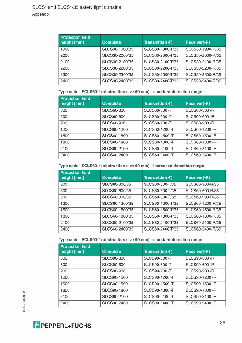
Type code "SCLS60-* (obstruction size 60 mm) - standard detection range
Type code "SCLS60-* (obstruction size 60 mm) - increased detection range
Type code "SCLS90-* (obstruction size 90 mm) - standard detection range
1900 SLCS30-1900/35 SLCS30-1900-T/35 SLCS30-1900-R/35
2000 SLCS30-2000/35 SLCS30-2000-T/35 SLCS30-2000-R/35
2100 SLCS30-2100/35 SLCS30-2100-T/35 SLCS30-2100-R/35
2200 SLCS30-2200/35 SLCS30-2200-T/35 SLCS30-2200-R/35
2300 SLCS30-2300/35 SLCS30-2300-T/35 SLCS30-2300-R/35
2400 SLCS30-2400/35 SLCS30-2400-T/35 SLCS30-2400-R/35
Protection field
height [mm] Complete Transmitter(-T) Receiver(-R)
300 SLCS60-300 SLCS60-300 -T SLCS60-300 -R
600 SLCS60-600 SLCS60-600 -T SLCS60-600 -R
900 SLCS60-900 SLCS60-900 -T SLCS60-900 -R
1200 SLCS60-1200 SLCS60-1200 -T SLCS60-1200 -R
1500 SLCS60-1500 SLCS60-1500 -T SLCS60-1500 -R
1800 SLCS60-1800 SLCS60-1800 -T SLCS60-1800 -R
2100 SLCS60-2100 SLCS60-2100 -T SLCS60-2100 -R
2400 SLCS60-2400 SLCS60-2400 -T SLCS60-2400 -R
Protection field
height [mm] Complete Transmitter(-T) Receiver(-R)
300 SLCS60-300/35 SLCS60-300-T/35 SLCS60-300-R/35
600 SLCS60-600/35 SLCS60-600-T/35 SLCS60-600-R/35
900 SLCS60-900/35 SLCS60-900-T/35 SLCS60-900-R/35
1200 SLCS60-1200/35 SLCS60-1200-T/35 SLCS60-1200-R/35
1500 SLCS60-1500/35 SLCS60-1500-T/35 SLCS60-1500-R/35
1800 SLCS60-1800/35 SLCS60-1800-T/35 SLCS60-1800-R/35
2100 SLCS60-2100/35 SLCS60-2100-T/35 SLCS60-2100-R/35
2400 SLCS60-2400/35 SLCS60-2400-T/35 SLCS60-2400-R/35
Protection field
height [mm] Complete Transmitter(-T) Receiver(-R)
300 SLCS90-300 SLCS90-300 -T SLCS90-300 -R
600 SLCS90-600 SLCS90-600 -T SLCS90-600 -R
900 SLCS90-900 SLCS90-900 -T SLCS90-900 -R
1200 SLCS90-1200 SLCS90-1200 -T SLCS90-1200 -R
1500 SLCS90-1500 SLCS90-1500 -T SLCS90-1500 -R
1800 SLCS90-1800 SLCS90-1800 -T SLCS90-1800 -R
2100 SLCS90-2100 SLCS90-2100 -T SLCS90-2100 -R
2400 SLCS90-2400 SLCS90-2400 -T SLCS90-2400 -R
Protection field
height [mm] Complete Transmitter(-T) Receiver(-R)

271
694
20
20-0
2
40
SLCS* and SLCS*/35 safety light curtainsAppendix
Type code "SCLS90-* (obstruction size 90 mm) - increased detection range
Protection field
height [mm] Complete Transmitter(-T) Receiver(-R)
300 SLCS90-300/35 SLCS90-300-T/35 SLCS90-300-R/35
600 SLCS90-600/35 SLCS90-600-T/35 SLCS90-600-R/35
900 SLCS90-900/35 SLCS90-900-T/35 SLCS90-900-R/35
1200 SLCS90-1200/35 SLCS90-1200-T/35 SLCS90-1200-R/35
1500 SLCS90-1500/35 SLCS90-1500-T/35 SLCS90-1500-R/35
1800 SLCS90-1800/35 SLCS90-1800-T/35 SLCS90-1800-R/35
2100 SLCS90-2100/35 SLCS90-2100-T/35 SLCS90-2100-R/35
2400 SLCS90-2400/35 SLCS90-2400-T/35 SLCS90-2400-R/35

SLCS* and SLCS*/35 safety light curtainsAppendix
271
694
20
20-0
2
41
8.5 Application Checklist
A list of important points should help you avoid errors when planning, setting up, and using the protective device. This application checklist is not complete and must be modified to suit each specific application.
Before Installation
■ Have all the applicable standards and regulations been observed?
■ Does the technical data of the SLCS meet the requirements of the application? This especially applies to detection capability, the protection field height, and the operating voltage.
■ Is the overvoltage category required by EN 50178 or EN 60947-1 met at the connections?
■ Is the electrical equipment, the wiring and the overcurrent protection designed in accordance with IEC 60204-1:2009?
■ Is there enough space for fitting and dismounting components?
■ Are the distances between the protection field and the hazardous area as well as the reflective surfaces maintained as required?
■ Is the SLCS used indoors?
After Installation
■ Is the startup enable input connected when the startup/restart interlock is activated?
■ Is the ready to start signal lamp connected?
■ Is the test input connected?
■ Is the red/green indicator for signaling the status of the OSSD outputs in a visible location?
■ Are all components correctly connected?
■ Has the SLCS been positioned so that the protection field cannot be bypassed and people cannot enter the hazardous area undetected?
■ Is the SLCS aligned?
■ Have the necessary safety distances been maintained?
Commissioning
■ Has the detection capability of the SLCS been tested over the entire protection field height using the test rod? This test should take place at multiple locations and at least once in front of the transmitter and receiver as well as at the central point between the transmitter and receiver.
■ Do the OSSD switch outputs trigger the requisite stop?
■ Has the response time of the overall protective device been checked?
Note
Observing Applicable Standards and Laws
The relevant laws and standards that apply to the use of opto-electronic safety devices must be followed. There are differences depending on the area of use.

271
694
20
20-0
2
42
SLCS* and SLCS*/35 safety light curtainsAppendix
Periodic Inspection
■ Have the requisite tests and test intervals been determined?
■ Is the detection capability of the SLCS tested regularly over the entire protection field height using the test rod?
■ Are the response times checked at regular intervals?
■ Is all machine safety equipment inspected at the required intervals?
■ Are all inspections documented?

SLCS* and SLCS*/35 safety light curtainsAppendix
271
694
20
20-0
2
43
8.6 Accessories
The following products are available as accessories:
Matching accessories for safety light curtains
No. Designation Illustration Description
1 OMH-SLCT-01 Mounting Aid
2 OMH-SLCT-02 Mounting Aid
3 OMH-SLCT-03 Mounting Aid
4 OMH-SLCT-04 Mounting Aid
5 OMH-SLCT-05 Mounting Aid
6 OMH-SLCT-10 Mounting Aid
7 OMH-SLCT-11 Mounting Aid

271
694
20
20-0
2
44
SLCS* and SLCS*/35 safety light curtainsAppendix
8 OMH-SLCT-12-500 Muting arm with round rod
9 OMH-07-01 Light barrier holder for muting round rod
10 OMH-SLCT-100-1200 Mounting profile for floor mounting
OMH-SLCT-100-1500
OMH-SLCT-100-2100
OMH-SLCT-100-2500
No. Designation Illustration Description

SLCS* and SLCS*/35 safety light curtainsAppendix
271
694
20
20-0
2
45
11 OMH-SLCT-110-1200 Mounting profile with decorative cover (front)OMH-SLCT-110-1500
OMH-SLCT-110-2100
OMH-SLCT-110-2500
12 OMH-SLCT-120-1200 Two lateral protective covers for mounting profileOMH-SLCT-120-1500
OMH-SLCT-120-2100
OMH-SLCT-120-2500
13 OMH-SLCT-200 Floor mount for soil column/mounting pro-file
No. Designation Illustration Description

271
694
20
20-0
2
46
SLCS* and SLCS*/35 safety light curtainsAppendix
Available Mounting Brackets
The mounting brackets enable light curtains and accessories to be mounted. A complete mounting bracket is required to mount a transmitter and a receiver. The mounting brackets are also suitable as a corner profile if two independently acting light curtains are to be installed. For compatible mounting brackets, use the search term SLCT-M*. on www.pepperl+fuchs.com.
8.6.1 Mounting Aid OMH-SLCT-01
Model number: OMH-SLCT-01
The emitters/receivers can be secured using mounting aids that grip the dovetail guide. There are dovetail guides on three sides of the profile. When mounting and aligning the unit, avoid subjecting the profile to mechanical tension.
A minimum of two mounting aids must be used to secure the emitter or receiver. If vibrations or shocks are expected, we recommend attaching mounting aids at intervals of 500 mm.
14 SLCT-M-01-1200 Inclined mirror for 90° deflection
SLCT-M-01-1500
SLCT-M-01-2100
SLCT-M-01-2500
15 AA SLCT-01 Profile alignment aid
16 TR 14/30/50/60 Test rod
No. Designation Illustration Description

SLCS* and SLCS*/35 safety light curtainsAppendix
271
694
20
20-0
2
47
8.6.2 Mounting Aid OMH-SLCT-02
Model number: OMH-SLCT-02
Figure 8.4 Dimensional drawing and assembly of the mounting aids OMH-SLCT-01 and OMH-SLCT-02
The OMH-SLCT-02 mounting aid is used as a fixed bearing and secures the position of the light curtain in the event of thermal expansion, vibration, or shock.
8.6.3 Mounting brackets OMH-SLCT-03 and OMH-SLCT-04
Model number (fixed bearing): OMH-SLCT-03
Model number (movable bearing): OMH-SLCT-04
The longer mounting aid OMH-SLCT-03 has a higher clamping force than the shorter mounting aid OMH-SLCT-04 and is therefore the preferred option for assuming the function of the fixed bearing. A minimum of one fixed bearing and one movable bearing is required to mount the device. If more than two mounting aids are required for reasons of stability, the use of additional movable bearings is recommended. If vibrations or shocks are expected, we recommend attaching mounting aids at intervals of 500 mm.
The mounting aid OMH-SLCT-03 can also be used to connect 2 safety light curtains or safety light grids. If the mounting aid is to be used for this application, the metal bracket should be removed.
8.6.4 Mounting Aid OMH-SLCT-05
Model number: OMH-SLCT-05
The OMH-SLCT-05 mounting aid is a robust, swiveling holder with very large pivoting range. The integrated dovetail groove terminal device enables the mounting of profiles from the SLCS or SLCT series without any additional accessories.
ø 4.3
8.3
16
ø 4
.3
61
.12
8
OMH-SLCT-02
OMH-SLCT-01
OMH-SLCT-02
OMH-SLCT-01
37
42.81
7.1

271
694
20
20-0
2
48
SLCS* and SLCS*/35 safety light curtainsAppendix
Features
■ Large pivoting range from -7° .. +110°
■ Very robust
■ Easily accessible screws
■ Integrated dovetail groove for mounting SLCS or SLCT
8.6.5 OMH-SLCT-12 -500 Muting arm with round rod
Mounting bracket, muting arm with round rod d=12 mm
■ Can be attached to groove in two directions
■ Fast assembly
8.6.6 OMH-07-01 Mounting bracket for circular profiles
Mounting bracket for circular profiles ø 12 mm or flat profiles 1.5 mm ... 3 mm
8.6.7 OMH-SLCT-100-xxxx Mounting profile for floor mounting
■ Eight grooves for mounting photoelectric sensors or accessories, three on the inside and five on the outside
■ Corner mounting of photoelectric sensors with a directional difference of 90°
■ Cover prepared for indicator light mounting
Figure 8.5 Example of mounting a mounting aid OMH-SLCT-01 to a mounting column
8.6.8 OMH-SLCT-110-xxxx Mounting profile with decorative cover (front)
Mounting base for floor mounting with rear panel and cover plate
■ Eight grooves for mounting photoelectric sensors or accessories, three on the inside and five on the outside
■ Corner mounting of photoelectric sensors with a directional difference of 90°
■ Cover prepared for indicator light mounting
■ Rear panel prepared for 3 sensors and 6 cable glands
8.6.9 OMH-SLCT-120-xxx Lateral protective covers for mounting profile
Lateral protection for the OMH-SLCT-100 and OMHSLCT- 110 mounting bases

SLCS* and SLCS*/35 safety light curtainsAppendix
271
694
20
20-0
2
49
8.6.10 OMH-SLCT-200 Floor mount for soil column/mounting profile
Features
■ Rotation of the SLCT-M- 01 inclined mirror around the physically preferred rotational axis
■ Vertical adjustment decoupled from rotation
■ Mounting on ground anchors
■ Lead-away of lines in floor via hole for NW29 coupling nut and corrugated hose
■ Base plate to compensate for uneven ground, particularly for brittle surfaces
■ Only approx. 20 mm in height from bottom edge of base plate to top edge of ground plate
8.6.11 SLCT-M-01-xxxx inclined mirror for 90° deflection
Features
■ Rotation-invariant deflection of a light beam by 90° in the plane of incidence, making it highly vibration-resistant
■ Translation-free deflection with no lateral beam shift with OMH-SLCT-200 floor mount
■ Silver-coated mirror glass
■ Mirror glass with low light absorption
■ Up to Ø 48 mm pencil of rays in the plane of incidence
8.6.12 Alignment aid
Order code: AA-SLCT-01
The transmitter and receiver should always be aligned at the same height in parallel to one another. The AA-SLCT-01 alignment aid with bubble level assists the perpendicular alignment of the profile. The AA-SLCT-01 alignment aid is simply clipped into the groove on the side of the profile.
Figure 8.6 Dimensional drawing and assembly of the alignment AA-SLCT-01
ø 21 24.5
11.1 ø 5.5
20
13
9
14
23.421.5
PU
SH
PU
SH
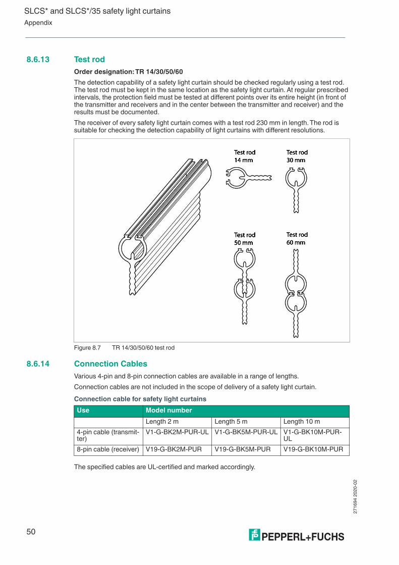
271
694
20
20-0
2
50
SLCS* and SLCS*/35 safety light curtainsAppendix
8.6.13 Test rod
Order designation: TR 14/30/50/60
The detection capability of a safety light curtain should be checked regularly using a test rod. The test rod must be kept in the same location as the safety light curtain. At regular prescribed intervals, the protection field must be tested at different points over its entire height (in front of the transmitter and receivers and in the center between the transmitter and receiver) and the results must be documented.
The receiver of every safety light curtain comes with a test rod 230 mm in length. The rod is suitable for checking the detection capability of light curtains with different resolutions.
Figure 8.7 TR 14/30/50/60 test rod
8.6.14 Connection Cables
Various 4-pin and 8-pin connection cables are available in a range of lengths.
Connection cables are not included in the scope of delivery of a safety light curtain.
Connection cable for safety light curtains
The specified cables are UL-certified and marked accordingly.
Use Model number
Length 2 m Length 5 m Length 10 m
4-pin cable (transmit-ter)
V1-G-BK2M-PUR-UL V1-G-BK5M-PUR-UL V1-G-BK10M-PUR-UL
8-pin cable (receiver) V19-G-BK2M-PUR V19-G-BK5M-PUR V19-G-BK10M-PUR

Pepperl+Fuchs Quality
Download our latest policy here:
www.pepperl-fuchs.com/quality
www.pepperl-fuchs.com
© Pepperl+Fuchs · Subject to modifications
Printed in Germany 271694 / DOCT-3847C