Embed Size (px)
Citation preview

1
The SLA5800 Series mass flow meters and mass flow controllers have gained broad acceptanceas the standard for accuracy, stability and reliability. These products have a wide flowmeasurement range and are suitable for a broad range of temperature and pressure conditionsmaking them well suite for applications in chemical and petrochemical research, laboratory,analytical, fuel cell and life science among others.
Highlights of the SLA5800 Series mass flow products include: industry leading long termstability, accuracy backed by superior metrology systems and methods using primary calibrationsystems directly traceable to international standards, and a broad range of analog and digitalI/O options to suite virtually any application. An independent diagnostic/service port permitsusers to troubleshoot or change flow conditions without removing the mass flow controllerfrom service.
The SLA5800 Series provides a highly configurable platform based on a simple modulararchitecture. The SLA5800 Series feature set was carefully selected to enable drop-inreplacement and upgrade of many brands of mass flow controllers. With the wide range ofoptions and features available, the SLA5800 Series provides users with a single platform tosupport a broad range of applications.
Data Sheet
SLA5800 SeriesThermal Mass Flow
OverviewOverviewOverviewOverviewOverview
PrPrPrPrProduct Descriptionoduct Descriptionoduct Descriptionoduct Descriptionoduct Description
Elastomer Sealed, Digital,Thermal Mass Flow Meters and Controllers
Model SLA5850
FeaturFeaturFeaturFeaturFeatures and Benefitses and Benefitses and Benefitses and Benefitses and Benefits
FeaturFeaturFeaturFeaturFeatureseseseses BenefitsBenefitsBenefitsBenefitsBenefits
Industry leading long term sensor stability Increased system uptime and reduced cost of ownership by reducing maintenance and eliminatingperiodic recipe adjustments and/or recalibrations
User accessible service port Simplified installation, start-up, troubleshooting and access to diagnostics provides maximum uptime
Advanced diagnostics Ensures device is operating within user specified limits for high process yield uptime
Superior valve technology Minimum leak-by, wide turndown, fast response and superior corrosion resistant materials reduces overallgas panel cost and increases throughput
Adaptable mechanical configurations Easily retrofit to existing systems
Primary standard calibration systems Ensures measurement accuracy is traceable to international standards
Simple modular design Easy-to-service elastomer sealed design provides for factory or field service maximizing uptime andreducing total cost of ownership
DS-TMF-SLA5800-Series-RevB-MFC-engJune, 2014

2
PrPrPrPrProduct Descriptionoduct Descriptionoduct Descriptionoduct Descriptionoduct Description
Advanced Thermal Flow Measurement SensorAdvanced Thermal Flow Measurement SensorAdvanced Thermal Flow Measurement SensorAdvanced Thermal Flow Measurement SensorAdvanced Thermal Flow Measurement SensorBrooks' sensor technology combines:• Excellent signal to noise performance for improved accuracy
at low setpoints• Superior long-term stability through enhanced sensor
manufacturing and burn in process• Isothermal packaging to reduce sensitivity to external
temperature changes
Advanced DiagnosticsAdvanced DiagnosticsAdvanced DiagnosticsAdvanced DiagnosticsAdvanced DiagnosticsThe mass flow controller remains the most complex and criticalcomponent in gas delivery systems. When dealing with highlytoxic or corrosive gases, removing the mass flow controller todetermine if it is faulty should be the last resort. In responseto this, Brooks pioneered smarter mass flow controllers withembedded self test routines and introduced an independentdiagnostic/service port to provide the user with a simpleinterface, for troubleshooting without disturbing flowcontroller operation.
Wide Flow RangeWide Flow RangeWide Flow RangeWide Flow RangeWide Flow RangeThe SLA5800 Series covers an extremely broad range of flowrates. Model SLA5850 can have a full scale flow as low as 3ccm. With a high turndown ratio of 100:1 for any full scalerange from 1-50 lpm N2 equivalent and 50:1 turndown for allother flow rates, accurate gas flow can be measured orcontrolled down to 0.06 ccm! Model SLA5853 can monitor orcontrol gas flows up to 2500 lpm.
Fast Response PerformanceFast Response PerformanceFast Response PerformanceFast Response PerformanceFast Response PerformanceThe all-digital electronics and superior mechanicalconfiguration in the SLA5800 Series provide for ultra fastresponse characteristics.
Broad Array of Communication OptionsBroad Array of Communication OptionsBroad Array of Communication OptionsBroad Array of Communication OptionsBroad Array of Communication OptionsBrooks offers traditional 0-5 volt and 4-20mA analog optionsas well as RS-485 digital communications (“S-protocol”, basedon HART) Brooks also offers control interfaces via digitalnetwork protocols like DeviceNet, a high speed (up to 500kbaud) digital communication network, and Profibus. Brooks'communication capabilities and device-profiles have beencertified by the ODVA (Open DeviceNet Vendor's Association)and the ITK (Interoperability Test Kit). Other network protocolsare in development. Talk to your Brooks representative aboutyour specific needs.
Multi-gas/Multi-range CapabilitiesMulti-gas/Multi-range CapabilitiesMulti-gas/Multi-range CapabilitiesMulti-gas/Multi-range CapabilitiesMulti-gas/Multi-range CapabilitiesThe SLA5800 Series multi-gas and multi-range capabilitiesreduce inventory. Storage and pre-programming of up to 6gas calibrations easily permits users to switch betweendifferent gasses and ranges on a single device.
3
PrPrPrPrProduct oduct oduct oduct oduct ApplicationsApplicationsApplicationsApplicationsApplications
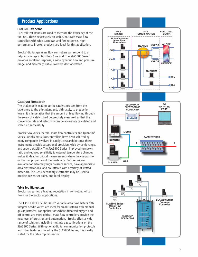
Fuel Cell Test StandFuel Cell Test StandFuel Cell Test StandFuel Cell Test StandFuel Cell Test StandFuel cell test stands are used to measure the efficiency of thefuel cell. These devices rely on stable, accurate mass flowcontrollers with wide turndown and fast response. High-performance Brooks' products are ideal for this application.
Brooks' digital gas mass flow controllers can respond to asetpoint change in less than 1 second. The SLA5800 Seriesprovides excellent response, a wide dynamic flow and pressurerange, and extremely stable, low zero drift operation.
Catalyst ResearchThe challenge is scaling up the catalyst process from thelaboratory to the pilot plant and, ultimately, to productionlevels. It is imperative that the amount of feed flowing throughthe research catalyst bed be precisely measured so that theconversion rate and selectivity can be accurately calculated andscaled up successfully.
Brooks' SLA Series thermal mass flow controllers and Quantim®
Series Coriolis mass flow controllers have been selected bymany companies involved in catalyst research because theseinstruments provide exceptional precision, wide dynamic range,and superb stability. The SLA5800 Series' improved turndownratio and reduced sensitivity to external temperature changesmakes it ideal for critical measurements where the compositionor thermal properties of the feeds vary. Both series areavailable for extremely high pressure service, have appropriatearea classifications, and are offered with a variety of wettedmaterials. The 0254 secondary electronics may be used toprovide power, set point, and local display.
TTTTTable able able able able TTTTTop Biorop Biorop Biorop Biorop BioreactorseactorseactorseactorseactorsBrooks has earned a leading reputation in controlling of gasflows for bioreactor applications.
The 1350 and 1355 Sho-RateTM variable area flow meters withintegral needle valves are ideal for small systems with manualgas adjustment. For applications where dissolved oxygen andpH control are more critical, mass flow controllers provide thenext level of precision and automation. Brooks offers a widerange of solutions including multiple gas calibrations on theSLA5800 Series. With optional digital communication protocolsand other features offered by the SLA5800 Series, it is ideallysuited for the table top bioreactor.
Brooks Instrument
TM
PRECISION MASS FLOW

4
PrPrPrPrProduct Specificationsoduct Specificationsoduct Specificationsoduct Specificationsoduct Specifications
SLA5850/60SLA5850/60SLA5850/60SLA5850/60SLA5850/60 SLA5851/61SLA5851/61SLA5851/61SLA5851/61SLA5851/61 SLA5853/63SLA5853/63SLA5853/63SLA5853/63SLA5853/63
* Response time can be improved upon request
PerformancePerformancePerformancePerformancePerformanceFlow AccuracyFlow AccuracyFlow AccuracyFlow AccuracyFlow Accuracy +0.9% of S.P. (20-100% F.S.), ±0.9% of S.P. (20-100% F.S.),
+0.18% of F.S. (2-20% F.S., 1-20% F.S. from 1-50 lpm) ±0.18% of F.S. (2-20% F.S.) up to 1100 lpm±1.0% of F.S. from 1100 lpm
up to 2500 lpm
Control RangeControl RangeControl RangeControl RangeControl Range 100:1 for F.S. from 1-50 lpm (50:1 for all other F.S. flows)
Repeatability & ReproducibilityRepeatability & ReproducibilityRepeatability & ReproducibilityRepeatability & ReproducibilityRepeatability & Reproducibility 0.20% S.P.
LinearityLinearityLinearityLinearityLinearity Included in accuracy
Response Time (Response Time (Response Time (Response Time (Response Time (Settling Time withinSettling Time withinSettling Time withinSettling Time withinSettling Time within < 1 second < 3 seconds±2% F.S. for 0-100% command step)*±2% F.S. for 0-100% command step)*±2% F.S. for 0-100% command step)*±2% F.S. for 0-100% command step)*±2% F.S. for 0-100% command step)*
Zero StabilityZero StabilityZero StabilityZero StabilityZero Stability < + 0.2% F.S. per year
Temperature CoefficientTemperature CoefficientTemperature CoefficientTemperature CoefficientTemperature Coefficient Zero: <0.05% of F.S. per °C. Span: <0.1% of S.P. per °C
Pressure CoefficientPressure CoefficientPressure CoefficientPressure CoefficientPressure Coefficient ±0.03% per psi (0-200 psi N2)
Attitude SensitivityAttitude SensitivityAttitude SensitivityAttitude SensitivityAttitude Sensitivity <0.2% F.S. maximum deviation from specified accuracy after re-zeroing
RatingsRatingsRatingsRatingsRatingsOperating Temperature RangeOperating Temperature RangeOperating Temperature RangeOperating Temperature RangeOperating Temperature Range 0-65oC (32-149oF)
Minimum Pressure DifferentialMinimum Pressure DifferentialMinimum Pressure DifferentialMinimum Pressure DifferentialMinimum Pressure Differential 5 psi/0.35 bar 10 psi/0.69 bar Min.: 7.5 psi/0.52 bar at 500 lpm(Controllers)(Controllers)(Controllers)(Controllers)(Controllers) Min.: 14.5 psi/1.00 bar at 1000 lpm
Min.: 35.0 psi/2.41 bar at 2500 lpm
Maximum Pressure DifferentialMaximum Pressure DifferentialMaximum Pressure DifferentialMaximum Pressure DifferentialMaximum Pressure Differential Application specific up to 50 psi/3.45 bar 300 psi/20.0 bar(Controllers)(Controllers)(Controllers)(Controllers)(Controllers) 1500 psi/103.4 bar
Leak Integrity (external)Leak Integrity (external)Leak Integrity (external)Leak Integrity (external)Leak Integrity (external) 1x10⁻⁹ atm. cc/sec He
MechanicalMechanicalMechanicalMechanicalMechanicalValve TypeValve TypeValve TypeValve TypeValve Type Normally Closed, Normally Open, Meter
Primary Wetted MaterialsPrimary Wetted MaterialsPrimary Wetted MaterialsPrimary Wetted MaterialsPrimary Wetted Materials 316L Stainless Steel, High Alloy Stainless Steel, Viton® fluoroelastomers, Buna-N, Kalrez®, Teflon®/Kalrez®, and EPDM
CertificationsCertificationsCertificationsCertificationsCertificationsMarkMarkMarkMarkMark AgencyAgencyAgencyAgencyAgency CertificationCertificationCertificationCertificationCertification Applicable StandardApplicable StandardApplicable StandardApplicable StandardApplicable Standard StatusStatusStatusStatusStatus
CE EMC Directive 2004/108/EC EN:61326-1:2006 Pass
UL (Recognized) Class I, Div 2, Group A, B, C, D CSA C22.2 NO. 213-M1987 Pending
ATEX II 3 G Ex nA IIC T4 Gc EN 60079-0:2012 Pending
EN 60079-15:2010
IECEx II 3 G Ex nA IIC T4 Gc IEC 60079-0:2011 Pending
IEC 60079-15:2010
Flow Ranges and PrFlow Ranges and PrFlow Ranges and PrFlow Ranges and PrFlow Ranges and Pressuressuressuressuressure Ratings:e Ratings:e Ratings:e Ratings:e Ratings:Mass FlowMass FlowMass FlowMass FlowMass Flow Mass FlowMass FlowMass FlowMass FlowMass Flow Flow RangesFlow RangesFlow RangesFlow RangesFlow Ranges Pressure UnitPressure UnitPressure UnitPressure UnitPressure Unit PED Module HPED Module HPED Module HPED Module HPED Module HControllerControllerControllerControllerController MeterMeterMeterMeterMeter N2 Eq. RatingsN2 Eq. RatingsN2 Eq. RatingsN2 Eq. RatingsN2 Eq. Ratings psi/barpsi/barpsi/barpsi/barpsi/bar CategoryCategoryCategoryCategoryCategory
ModelModelModelModelModel ModelModelModelModelModel Min. F.S.Min. F.S.Min. F.S.Min. F.S.Min. F.S. Max. F.S.Max. F.S.Max. F.S.Max. F.S.Max. F.S. StandardStandardStandardStandardStandard OptionalOptionalOptionalOptionalOptional
SLA5850 SLA5860 0.003 50 lpm 1500 psi/100 bar 4500 psi/310 bar SEP
SLA5851 SLA5861 15 100 lpm* 1500 psi/100 bar NA** SEP
SLA5853 SLA5863 100 2500 lpm 1000 psi/70 bar NA 1 for all 150 lb flanges2 for all other connections
* 200 lpm of H2 possible, 600 lpm of H2 possible with decreased accuracy** 4500 psi/310 bar available as a special on the SLA5861 only
* Alarm modes are dependent on the communications interface. These are described in the corresponding digital communication interface manual.
DiagnosticsDiagnosticsDiagnosticsDiagnosticsDiagnosticsStatus LightsStatus LightsStatus LightsStatus LightsStatus Lights MFC Health, Network Status
Alarms*Alarms*Alarms*Alarms*Alarms* Sensor Output, Control Valve Output, Over Temperature, Power Surge/Sag, Network Interruption
Diagnostic/Service PortDiagnostic/Service PortDiagnostic/Service PortDiagnostic/Service PortDiagnostic/Service Port RS485 via 2.5mm jack

5
Electrical SpecificationsElectrical SpecificationsElectrical SpecificationsElectrical SpecificationsElectrical Specifications
Communication ProtocolCommunication ProtocolCommunication ProtocolCommunication ProtocolCommunication Protocol RS485RS485RS485RS485RS485 ProfibusProfibusProfibusProfibusProfibus®®®®® DeviceNetDeviceNetDeviceNetDeviceNetDeviceNetTMTMTMTMTM
Electrical ConnectionElectrical ConnectionElectrical ConnectionElectrical ConnectionElectrical Connection 1 x 15-pin Male Sub-D, 1 x 15-pin Male Sub-D/ 1 x M12 with(A) 1 x 9-pin Female threaded coupling nut
Sub-D (B)
Analog I/OAnalog I/OAnalog I/OAnalog I/OAnalog I/O 0-5 V, 1-5 V, 0-10 V, N/A0-20 mA, 4-20 mA
Power Max./PurgePower Max./PurgePower Max./PurgePower Max./PurgePower Max./Purge From +13.5 Vdc to From +11 Vdc to+27 Vdc +25 Vdc
Power Requirements Watts, Max.Power Requirements Watts, Max.Power Requirements Watts, Max.Power Requirements Watts, Max.Power Requirements Watts, Max. Valve Orifice > 0.032”: 8 W Valve Orifice > 0.032”: 10 WValve Orifice ≤ 0.032”: 5 W Valve Orifice ≤ 0.032”: 7 W
Without Valve: 2 W Without Valve: 4 W
Voltage Set Point Input SpecificationsVoltage Set Point Input SpecificationsVoltage Set Point Input SpecificationsVoltage Set Point Input SpecificationsVoltage Set Point Input Specifications
Nominal RangeNominal RangeNominal RangeNominal RangeNominal Range 0-5 Vdc, 1-5 Vdc or 0-10 Vdc N/A
Full RangeFull RangeFull RangeFull RangeFull Range (-0.5)-11 Vdc N/A
Absolute Max.Absolute Max.Absolute Max.Absolute Max.Absolute Max. 18 V (without damage) N/A
Input ImpedenceInput ImpedenceInput ImpedenceInput ImpedenceInput Impedence >990 kOhms N/A
Required Max. Sink CurrentRequired Max. Sink CurrentRequired Max. Sink CurrentRequired Max. Sink CurrentRequired Max. Sink Current 0.002 mA N/A
Current Set Point Input SpecificationsCurrent Set Point Input SpecificationsCurrent Set Point Input SpecificationsCurrent Set Point Input SpecificationsCurrent Set Point Input Specifications
Nominal RangeNominal RangeNominal RangeNominal RangeNominal Range 4-20 mA or 0-20 mA N/A
Full RangeFull RangeFull RangeFull RangeFull Range 0-22 mA N/A
Absolute Max.Absolute Max.Absolute Max.Absolute Max.Absolute Max. 24 mA (without damage) N/A
Input ImpedenceInput ImpedenceInput ImpedenceInput ImpedenceInput Impedence 100 Ohms N/A
Flow Output (Voltage) SpecificationsFlow Output (Voltage) SpecificationsFlow Output (Voltage) SpecificationsFlow Output (Voltage) SpecificationsFlow Output (Voltage) Specifications
Nominal RangeNominal RangeNominal RangeNominal RangeNominal Range 0-5 Vdc, 1-5 Vdc or 0-10 Vdc N/A
Full RangeFull RangeFull RangeFull RangeFull Range (-1)-11 Vdc N/A
Min Load ResistanceMin Load ResistanceMin Load ResistanceMin Load ResistanceMin Load Resistance 2 kOhms N/A
Flow Output (Current) SpecificationsFlow Output (Current) SpecificationsFlow Output (Current) SpecificationsFlow Output (Current) SpecificationsFlow Output (Current) Specifications
Nominal RangeNominal RangeNominal RangeNominal RangeNominal Range 0-20 mA or 4-20 mA N/A
Full RangeFull RangeFull RangeFull RangeFull Range 0-22 mA (@ 0-20 mA); 3.8-22 mA (@ 4-20 mA) N/A
Max. LoadMax. LoadMax. LoadMax. LoadMax. Load 380 Ohms (for supply voltage: < 16 Vdc) N/A 580 Ohms (for supply voltage: ≥ 16 Vdc)
Analog I/O Alarm Ouput*Analog I/O Alarm Ouput*Analog I/O Alarm Ouput*Analog I/O Alarm Ouput*Analog I/O Alarm Ouput*
TypeTypeTypeTypeType Open Collector N/A
Max. Closed (On) CurrentMax. Closed (On) CurrentMax. Closed (On) CurrentMax. Closed (On) CurrentMax. Closed (On) Current 25 mA N/A
Max. Open (Off) LeakageMax. Open (Off) LeakageMax. Open (Off) LeakageMax. Open (Off) LeakageMax. Open (Off) Leakage 1μA N/A
Max. Open (Off) VoltageMax. Open (Off) VoltageMax. Open (Off) VoltageMax. Open (Off) VoltageMax. Open (Off) Voltage 30 Vdc N/A
Analog I/O Valve Override Signal Specifications**Analog I/O Valve Override Signal Specifications**Analog I/O Valve Override Signal Specifications**Analog I/O Valve Override Signal Specifications**Analog I/O Valve Override Signal Specifications**
Floating/UnconnectedFloating/UnconnectedFloating/UnconnectedFloating/UnconnectedFloating/Unconnected Instrument controls valve to command set point N/A
VOR < 0.3 VdcVOR < 0.3 VdcVOR < 0.3 VdcVOR < 0.3 VdcVOR < 0.3 Vdc Valve Closed N/A
1 Vdc < VOR < 4 Vdc1 Vdc < VOR < 4 Vdc1 Vdc < VOR < 4 Vdc1 Vdc < VOR < 4 Vdc1 Vdc < VOR < 4 Vdc Valve Normal N/A
VOR > 4.8 VdcVOR > 4.8 VdcVOR > 4.8 VdcVOR > 4.8 VdcVOR > 4.8 Vdc Valve Open N/A
Input ImpedenceInput ImpedenceInput ImpedenceInput ImpedenceInput Impedence 800 kOhms N/A
Absolute Max. InputAbsolute Max. InputAbsolute Max. InputAbsolute Max. InputAbsolute Max. Input (-25 Vdc) < VOR < 25 Vdc (without damage) N/A*The Alarm Output is an open collector or "contact type" that is CLOSED (on) whenever an alarm is active.
The Alarm Output may be set to indicate any one of various alarm conditions.** The Valve Override Signal (VOR) is implemented as an analog input which measures the voltage at the input and controls the
valve based upon the measured reading as shown in this section.

6
PrPrPrPrProduct Dimensionsoduct Dimensionsoduct Dimensionsoduct Dimensionsoduct Dimensions
SLA5850, Thru-Flow, RS485
SLA5850, Downport, RS485

7
PrPrPrPrProduct Dimensions (conoduct Dimensions (conoduct Dimensions (conoduct Dimensions (conoduct Dimensions (continued)tinued)tinued)tinued)tinued)
SLA5860, Thru-Flow, RS485
SLA5860, Thru-Flow, Profibus

8
PrPrPrPrProduct Dimensions (conoduct Dimensions (conoduct Dimensions (conoduct Dimensions (conoduct Dimensions (continued)tinued)tinued)tinued)tinued)
SLA5851, Thru-Flow, DeviceNet
SLA5861, Thru-Flow, RS485

9
PrPrPrPrProduct Dimensions (conoduct Dimensions (conoduct Dimensions (conoduct Dimensions (conoduct Dimensions (continued)tinued)tinued)tinued)tinued)
SLA5853, Thru-Flow, Profibus
SLA5863, Thru-Flow, DeviceNet

10
Model CodeModel CodeModel CodeModel CodeModel CodeCode DescriptionCode DescriptionCode DescriptionCode DescriptionCode Description Code OptionCode OptionCode OptionCode OptionCode Option Option DescriptionOption DescriptionOption DescriptionOption DescriptionOption Description
I.I.I.I.I. Base Model Numbers SLASLASLASLASLA Smart Link Advantage
II.II.II.II.II. Package / Finish Specifications 5858585858 Standard Elastomer Series
III.III.III.III.III. Function 55555 Mass Flow Controller66666 Mass Flow Meter
IV.IV.IV.IV.IV. Gas or Range 00000 3 ccm - 50 lpm11111 20 - 100 lpm33333 100 - 2500 lpm
V.V.V.V.V. Digital I/O Communication AAAAA None (select applicable analog I/O)DDDDD DeviceNet I/O (with 5-pin micro connector)PPPPP Profibus (2x sub-D)SSSSS RS485 (select applicable analog I/O)
VI.VI.VI.VI.VI. Mechanical Connection 1A1A1A1A1A Without adapters, 9/16” - 18 UNF(Body size 0 & 1 only) 1B1B1B1B1B 1/4” tube compression
1C1C1C1C1C 1/8” tube compression1D1D1D1D1D 3/8” tube compression1E1E1E1E1E 1/4” VCR1F1F1F1F1F 1/4” VCO1G1G1G1G1G 1/4” NPT1H1H1H1H1H 6mm tube compression1J1J1J1J1J 10mm tube compression1L1L1L1L1L 3/8”-1/2” VCR1M1M1M1M1M 3/8”-1/2” VCO1P1P1P1P1P 1/2” tube compression1S1S1S1S1S Elastomer downport1T1T1T1T1T 1/4” RC (BSP)1Y1Y1Y1Y1Y 3mm tube compressionB1B1B1B1B1 1/4” tube compression w/FilterC1C1C1C1C1 1/8” tube compression w/FilterD1D1D1D1D1 3/8” tube compression w/FilterE1E1E1E1E1 1/4” VCR w/FilterF1F1F1F1F1 1/4” VCO w/FilterG1G1G1G1G1 1/4” NPT w/FilterH1H1H1H1H1 6mm tube compression w/FilterJ1J1J1J1J1 10mm tube compression w/FilterL1L1L1L1L1 3/8”-1/2” VCR w/FilterM1M1M1M1M1 3/8”-1/2” VCO w/FilterP1P1P1P1P1 1/2” tube compression w/FilterT1T1T1T1T1 1/4” RC (BSP) w/FilterY1Y1Y1Y1Y1 3mm tube compression w/Filter
VI.VI.VI.VI.VI. Mechanical Connection 2A2A2A2A2A Without adapters, 9/16” - 18 UNF(Body size 3 only) 2B2B2B2B2B 1-1/16”-12 SAE/MS
2C2C2C2C2C 3/8” tube compression2D2D2D2D2D 1/2” tube compression2E2E2E2E2E 3/4” tube compression2F2F2F2F2F 1” tube compression2G2G2G2G2G 1/2” NPT (F)2H2H2H2H2H 1” NPT (F)2J2J2J2J2J 1-1/2” NPT (F)2K2K2K2K2K 1/2” VCO2L2L2L2L2L 3/4” VCO2M2M2M2M2M 1/2” VCR2N2N2N2N2N 1/2” RC (BSP)2P2P2P2P2P 1” RC (BSP)2R2R2R2R2R 1-5/16”-12 SAE/MS2S2S2S2S2S 1” VCO2T2T2T2T2T 3/4” VCR2U2U2U2U2U 1” VCR3A3A3A3A3A DIN DN15 PN40 Flange3B3B3B3B3B DIN DN25 PN40 Flange3C3C3C3C3C DIN DN40 PN40 Flange3D3D3D3D3D DIN DN15 PN40 Flange3E3E3E3E3E ANSI 1/2” 150# RF Flange3F3F3F3F3F ANSI 1/2” 300# RF Flange3G3G3G3G3G ANSI 1” 150# RF Flange3H3H3H3H3H ANSI 1” 300# RF Flange3J3J3J3J3J ANSI 1-1/2” 150# RF Flange3K3K3K3K3K ANSI 1-1/2” 300# RF Flange

11
Model Code (conModel Code (conModel Code (conModel Code (conModel Code (continued)tinued)tinued)tinued)tinued)
Sample Standard Model CodeSample Standard Model CodeSample Standard Model CodeSample Standard Model CodeSample Standard Model CodeIIIII IIIIIIIIII IIIIIIIIIIIIIII IVIVIVIVIV VVVVV VIVIVIVIVI VIIVIIVIIVIIVII VIIIVIIIVIIIVIIIVIII IXIXIXIXIX XXXXX XIXIXIXIXI XIIXIIXIIXIIXII XIIIXIIIXIIIXIIIXIII
SLASLASLASLASLA 5858585858 55555 00000 AAAAA 1A1A1A1A1A AAAAA BBBBB 11111 BBBBB 11111 AAAAA 11111
Code DescriptionCode DescriptionCode DescriptionCode DescriptionCode Description Code OptionCode OptionCode OptionCode OptionCode Option Option DescriptionOption DescriptionOption DescriptionOption DescriptionOption DescriptionVII.VII.VII.VII.VII. O-ring Material AAAAA Viton
BBBBB BunaCCCCC PTFEDDDDD KalrezEEEEE EPDMJJJJJ FDA/USP Class VI - VitonLLLLL FDA/USP Class VI - EPDM
VIII.VIII.VIII.VIII.VIII. Valve Seat AAAAA None (Sensor only)BBBBB Viton (for body size 3, diaphragm material = PTFE)CCCCC Buna (for body size 3, diaphragm material = PTFE)DDDDD Kalrez (for body size 3, diaphragm material = PTFE)EEEEE EPDM (for body size 3, diaphragm material = PTFE)FFFFF PTFEGGGGG Metal (for body size 3, diaphragm material = PTFE)
IX.IX.IX.IX.IX. Valve Type 00000 None (Sensor only)11111 Normally closed22222 Normally closed (Pressure diff. >30 psig (2 bar))33333 Normally closed (Pressure diff.<30 psig (2 bar))44444 Normally closed - high pressure55555 Normally open
X.X.X.X.X. Analog I/O AAAAA None - Digital Communications onlyCommunications BBBBB 0-5 Volt 0-5 Volt 15-pin D-conn
CCCCC 4-20 mA 4-20 mA 15-pin D-connLLLLL 1-5 Volt 1-5 Volt 15-pin D-connMMMMM 0-20 mA 0-20 mA 15-pin D-conn00000 0-10 Volt 0-10 Volt 15-pin D-conn11111 0-5 Volt 4-20 mA 15-pin D-conn22222 0-5 Volt 0-20 mA 15-pin D-conn33333 4-20 mA 0-5 Volt 15-pin D-conn44444 0-20 mA 0-5 Volt 15-pin D-conn99999 0-10 Volt 0-5 Volt 15-pin D-conn
XI.XI.XI.XI.XI. Power Supply Inputs 11111 ±15 Vdc22222 24 Vdc
XII.XII.XII.XII.XII. Output Enhancements AAAAA Standard response
BBBBB Fast response
XIII.XIII.XIII.XIII.XIII. Certification 11111 Safe Area

Brooks is committed to assuring all of our customers receive the ideal flow solution for their application, along with outstandingservice and support to back it up. We operate first class repair facilities located around the world to provide rapid response andsupport. Each location utilizes primary standard calibration equipment to ensure accuracy and reliability for repairs andrecalibration and is certified by our local Weights and Measures Authorities and traceable to the relevant International Standards.
Visit www.BrooksInstrument.com to locate the service location nearest to you.
STSTSTSTSTARARARARARTTTTT-UP SERVICE -UP SERVICE -UP SERVICE -UP SERVICE -UP SERVICE AND IN-SITU CALIBRAAND IN-SITU CALIBRAAND IN-SITU CALIBRAAND IN-SITU CALIBRAAND IN-SITU CALIBRATIONTIONTIONTIONTION
Brooks Instrument can provide start-up service prior to operation when required. For some process applications, where ISO-9001Quality Certification is important, it is mandatory to verify and/or (re)calibrate the products periodically. In many cases this servicecan be provided under in-situ conditions, and the results will be traceable to the relevant international quality standards.
CUSTCUSTCUSTCUSTCUSTOMER SEMINARS OMER SEMINARS OMER SEMINARS OMER SEMINARS OMER SEMINARS AND AND AND AND AND TRAININGTRAININGTRAININGTRAININGTRAINING
Brooks Instrument can provide customer seminars and dedicated training to engineers, end users, and maintenance persons.
Please contact your nearest sales representative for more details.
HELP DESKHELP DESKHELP DESKHELP DESKHELP DESKIn case you need technical assistance:
USA
+6297 9741
Due to Brooks Instrument's commitment to continuous improvement of our products, all specifications are subject to change without notice.
BrBrBrBrBrooks Service and Supportooks Service and Supportooks Service and Supportooks Service and Supportooks Service and Support
TRADEMARKSAera ............................................................... Advanced Energy Industries, Inc.Brooks ........................................................................... Brooks Instrument, LLCCelerity .......................................................................... Brooks Instrument, LLCDeviceNet ......................................... Open DeviceNet Vendors Association, Inc.EtherCAT ................................................................ EtherCat Technology GroupHART ........................................................... HART Communications FoundationHastelloy .......................................................................... Haynes InternationalKalrez .............................................................. DuPont Performance ElastomersMultiFlo ......................................................................... Brooks Instrument, LLCProfibus .......................................................................... Profibus InternationalUnit ............................................................................... Brooks Instrument, LLCVCR .................................................................................... Swagelok CompanyViton ............................................................... DuPont Performance ElastomersXacTorr .......................................................................... Brooks Instrument, LLC
Votre contact Brooks Instrument : Serv’Instrumentation
Z.I Broteau Nord 69540 Irigny
France Tél : +33 (0)4 78 51 47 50 Fax : +33 (0)4 78 51 59 96
Email : [email protected] Web : www.servinstrumentation.fr


![J org Pretz arXiv:2005.12203v1 [physics.class-ph] 25 May 2020 › pdf › 2005.12203.pdf · (t)/ m mass 1 mass 2 mass 3 mass 4 mass 5 mass 6 mass 7 mass 8 mass 9 mass 10 Figure 2](https://img.dokumen.tips/doc/110x75/5f1ec529f26656179f60ee75/j-org-pretz-arxiv200512203v1-25-may-2020-a-pdf-a-200512203pdf-t.jpg)