Embed Size (px)
Citation preview
SKYSCREENAssembly, Tensioning & Installation InstructionsParts Diagram
Roller Surface 2
Page 2 of 8
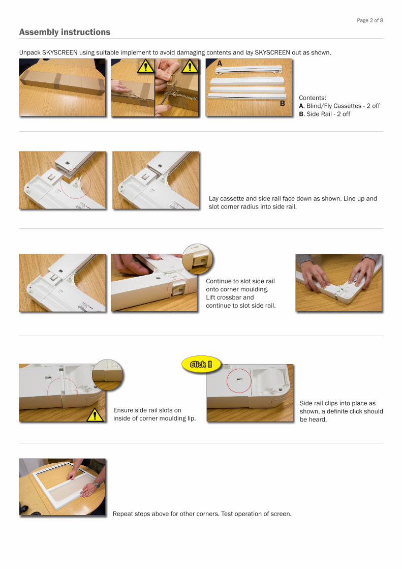
Unpack SKYSCREEN using suitable implement to avoid damaging contents and lay SKYSCREEN out as shown.
A
BContents:A. Blind/Fly Cassettes - 2 offB. Side Rail - 2 off
Lay cassette and side rail face down as shown. Line up and slot corner radius into side rail.
Continue to slot side rail onto corner moulding.Lift crossbar and continue to slot side rail.
Ensure side rail slots on inside of corner moulding lip.
Side rail clips into place as shown, a definite click should be heard.
Click !!
Repeat steps above for other corners. Test operation of screen.
Assembly instructions
Page 3 of 8
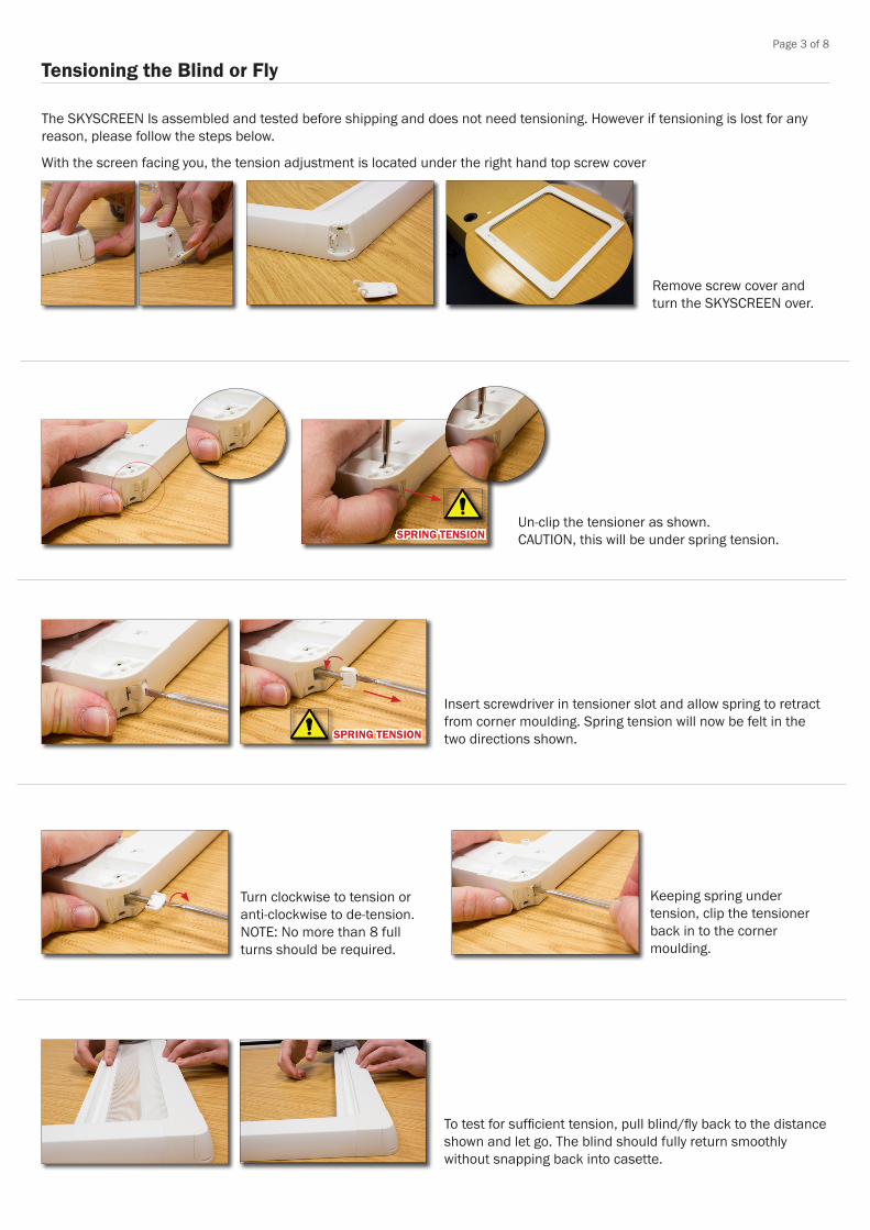
Tensioning the Blind or Fly
With the screen facing you, the tension adjustment is located under the right hand top screw cover
Remove screw cover and turn the SKYSCREEN over.
SPRING TENSIONUn-clip the tensioner as shown. CAUTION, this will be under spring tension.
SPRING TENSION
Insert screwdriver in tensioner slot and allow spring to retract from corner moulding. Spring tension will now be felt in the two directions shown.
Keeping spring under tension, clip the tensioner back in to the corner moulding.
Turn clockwise to tension or anti-clockwise to de-tension.NOTE: No more than 8 full turns should be required.
To test for sufficient tension, pull blind/fly back to the distance shown and let go. The blind should fully return smoothly without snapping back into casette.
The SKYSCREEN Is assembled and tested before shipping and does not need tensioning. However if tensioning is lost for any reason, please follow the steps below.

Page 4 of 8
1
2
x 4
Open screw covers as shown.
Insert and tighten screws in each corner using screwdriver, do not use electric screwdriver.Note:If the screen is to be fitted on to a soft headlining, we recommend the use of M4 plastic washers (not supplied) to shim between the screen and headlining. This will help to avoid distortion of the frame and over compressing the headlining material.
1
2
x 4
3
Installing the SKYSCREEN
Turn over and remove protective covers from adhesive pads in each corner.
Ensuring mounting surfaces are free form dust or grease, use the adhesive pads to hold the SKYCREEN in position and drill pilot holes. Ensure that the thickness of the boat structure at the proposed mounting position is deep enough to prevent the fixing screws from breaking through. Oceanair recommend No6 x 16mm [5/8”] PANHEAD Screws (not provided). However if necessary, use shorter fixing screws and use masking tape on the drill bit as a depth guide to avoid drilling too deep.
x 4
1
2
x 4
4
1
2
5
Close screw covers.
6Check operation of SKYSCREEN.
Before installation• Measure the SKYSCREEN and make sure it is the correct size.• Make sure the unit is fitted to a flat surface to avoid forcing the unit out of shape when fixing.• If SKYSCREEN is large; ensure a minimum of two people undertake the installation. • Ensure that the SKYSCREEN is the correct way up and in the desired orientation.• Make sure that the SKYSCREEN is not twisted; distortion will damage the blind and affect operation.
Page 5 of 8
Oceanair Marine Ltd Chichester PO20 0AY Englandt +44 (0)1243 606909 f +44 (0)1243 608300 www.oceanair.co.uk e [email protected]
© Oceanair marine Ltd 2014 OAT00421 Rev1 ECN 11739 November 2014
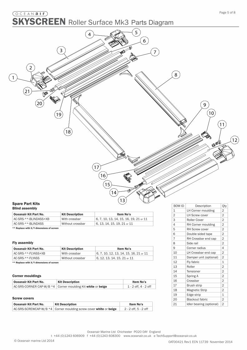
SKYSCREEN Roller Surface Mk3 Parts Diagram
1
17
5
3
64
7
2
19
20
21
8
18
9
10
11
12
16
13
15
14
1
17
5
3
64
7
2
19
20
21
8
18
9
10
11
12
16
13
15
14
Corner mouldings
Oceanair Kit Part No. Kit Description Item No’sAC-SRS-CORNER CAP-W/B *4 Corner moulding Kit white or beige 1 - 2 off, 4 - 2 off
Spare Part KitsBlind assembly
Oceanair Kit Part No. Kit Description Item No’sAC-SRS-**-BLINDASS+XB With crossbar 6, 7, 10, 13, 14, 15, 16, 19, 21 or 11AC-SRS-**-BLINDASS Without crossbar 6, 13, 14, 15, 19, 21 or 11
** Replace with X/Y dimensions of screen
BOM ID Description Qty1 LH Corner moulding 22 LH Screw cover 23 Roller Cover 24 RH Corner moulding 25 RH Screw cover 26 Double sided tape 27 RH Crossbar end cap 28 Side rail 29 Corner radius 410 LH Crossbar end cap 211 Damper unit (optional) 212 Fly fabric 113 Roller 214 Tensioner 215 Spring A 216 Crossbar 217 Brush strip 218 Magnetic Strip 219 Edge strip 120 Blackout fabric 221 Idler bearing (optional) 2
Fly assembly
Oceanair Kit Part No. Kit Description Item No’sAC-SRS-**-FLYASS+XB With crossbar 6, 7, 10, 12, 13, 14, 15, 16, 21 or 11AC-SRS-**-FLYASS Without crossbar 6, 12, 13, 14, 15, 21 or 11
** Replace with X/Y dimensions of screen
Screw covers
Oceanair Kit Part No. Kit Description Item No’sAC-SRS-SCREWCAP-W/B *4 Corner moulding screw cover white or beige 2 - 2 off, 5 - 2 off

Page 6 of 8
Notes

Page 7 of 8
Notes

Oceanair Marine Ltd.Atlantic House, 1 Ellis Square, Selsey, Chichester PO20 0AY United Kingdom.Tel: +44 1243 606909 Fax: +44 1243 608300 www.oceanair.co.uk
Registered OfficeAtlantic House, 1 Ellis Square, Selsey, Chichester PO20 0AYRegistered in England No. 2504633A member of the British Marine Federation
© Oceanair Marine Ltd 2013 Certificate No. SP240137 Registration No. 0044/1
ISO 9001Registered Firm
InternationalAccreditation Board
Part No. 700000288 Rev 2 ECN 11753 November 2014