Embed Size (px)
Citation preview
Skyrmion based microwave detectors and harvesting
G. Finocchio,1 M. Ricci,2 R. Tomasello,3 A. Giordano,1 M. Lanuzza,3 V. Puliafito,4
P. Burrascano,2 B. Azzerboni,4 and M. Carpentieri51Department of Mathematical and Computer Sciences, Physical Sciences and Earth Sciences, Universityof Messina, Viale F. Stagno d’Alcontres 31, 98166 Messina, Italy2Department of Engineering, Polo Scientifico Didattico di Terni, University of Perugia, Terni, TR I-50100,Italy3Department of Computer Science, Modelling, Electronics and System Science, University of Calabria,via P. Bucci 41C, I-87036 Rende (CS), Italy4Department of Engineering, University of Messina, c.da di Dio, I-98166 Messina, Italy5Department of Electrical and Information Engineering, Politecnico di Bari, via E. Orabona 4, I-70125 Bari,Italy
(Received 29 September 2015; accepted 11 December 2015; published online 28 December 2015)
Magnetic skyrmions are topologically protected states that are very promising for the design of the
next generation of ultra-low-power electronic devices. In this letter, we propose a magnetic tunnel
junction based spin-transfer torque diode with a magnetic skyrmion as ground state and a perpen-
dicular polarizer patterned as nano-contact for a local injection of the current. The key result is the
possibility to achieve sensitivities (i.e., detection voltage over input microwave power) larger than
2000 V/W for optimized contact diameters. We also pointed out that large enough voltage con-
trolled magnetocrystalline anisotropy could significantly improve the sensitivity. Our results can be
very useful for the identification of a class of spin-torque diodes with a non-uniform ground state
and to understand the fundamental physics of the skyrmion dynamical properties. VC 2015AIP Publishing LLC. [http://dx.doi.org/10.1063/1.4938539]
The spin-transfer torque diode (STD) effect is a rectifi-
cation effect that converts a microwave current in a dc volt-
age.1 The physics at the basis of the STD effect is linked to
the excitation of the ferromagnetic resonance (FMR). In par-
ticular, for a fixed input frequency, the detection voltage Vdc
is proportional to the amplitude of the microwave current Iac,
to the oscillating magneto-resistance DRs, and to the cosine
of the phase difference between the two previous signals Us,
Vdc ¼ 12
IacDRs cosðUsÞ. Since its discovery in 2005,1 due to
the low sensitivity equal to 1.4 V/W (rectified voltage over
input microwave power), this effect has been used only to
estimate the torques in magnetic tunnel junctions (MTJs),2,3
although specific calculations from Ref. 4 suggested that
optimized MTJs should reach sensitivities exceeding
10 000 V/W.
From an experimental point of view, the STD sensitivity
has been improved by the simultaneous application of a
microwave together with a bias current.5–7 In this case, an
additional component proportional to the dc current can con-
tribute to increase the detection voltage.8,9 Considering the
advances in the design of the MTJs, in terms of tunneling
magnetoresistive (TMR) effect and voltage controlled mag-
netocrystalline anisotropy (VCMA),10 and the understanding
of strong non-linear effects, such as stochastic resonance,9
non-linear resonance,6 and injection locking,7 the sensitivity
performance of biased STD has reached values as large as
75 000 V/W.7 Those results on biased STDs open a path for
the design of a generation of high sensitivity microwave
detectors. On the other hand, unbiased STDs could be also
designed to rectify the microwave power from different
energy sources, such as satellite, sound, television, and Wi-
Fi signals. The resulting dc voltage could charge a cell phone
battery, or supply self-powered sensors as well as other small
electronic devices. Therefore, the unbiased STDs can be
used for both passive microwave detection and power har-
vesting functionality. Up to now, unbiased STDs have been
designed with a uniform ground state and, thanks to the use
of both VCMA and spin-transfer torque, a sensitivity of
900 V/W has been measured.7,10
Very recently, the stabilization of N�eel skyrmions at
room temperature has been demonstrated by several groups
independently.11,12 This experimental milestone in the devel-
opment of ultralow-power devices has motivated the study
presented in this letter. We report the results of micromag-
netic simulations of STDs where a N�eel skyrmion is the
magnetic ground state of the free layer. We have considered
the diode effect of the skyrmion based STD as response to a
microwave current locally injected into the ferromagnet via
a nano-contact.
The key quantitative result of this letter is the prediction
of sensitivities reaching 2000 V/W at zero field, zero bias
current, and low input microwave power (<1.0 lW). Our
findings are interesting from a technological point of view,
in fact skyrmion based STD can be the basis for the design
of passive nano-contact microwave detectors and resonant
energy harvesting.13,14 The last part of this work shows the
effect of VCMA on the dynamical response of the skyrmion.
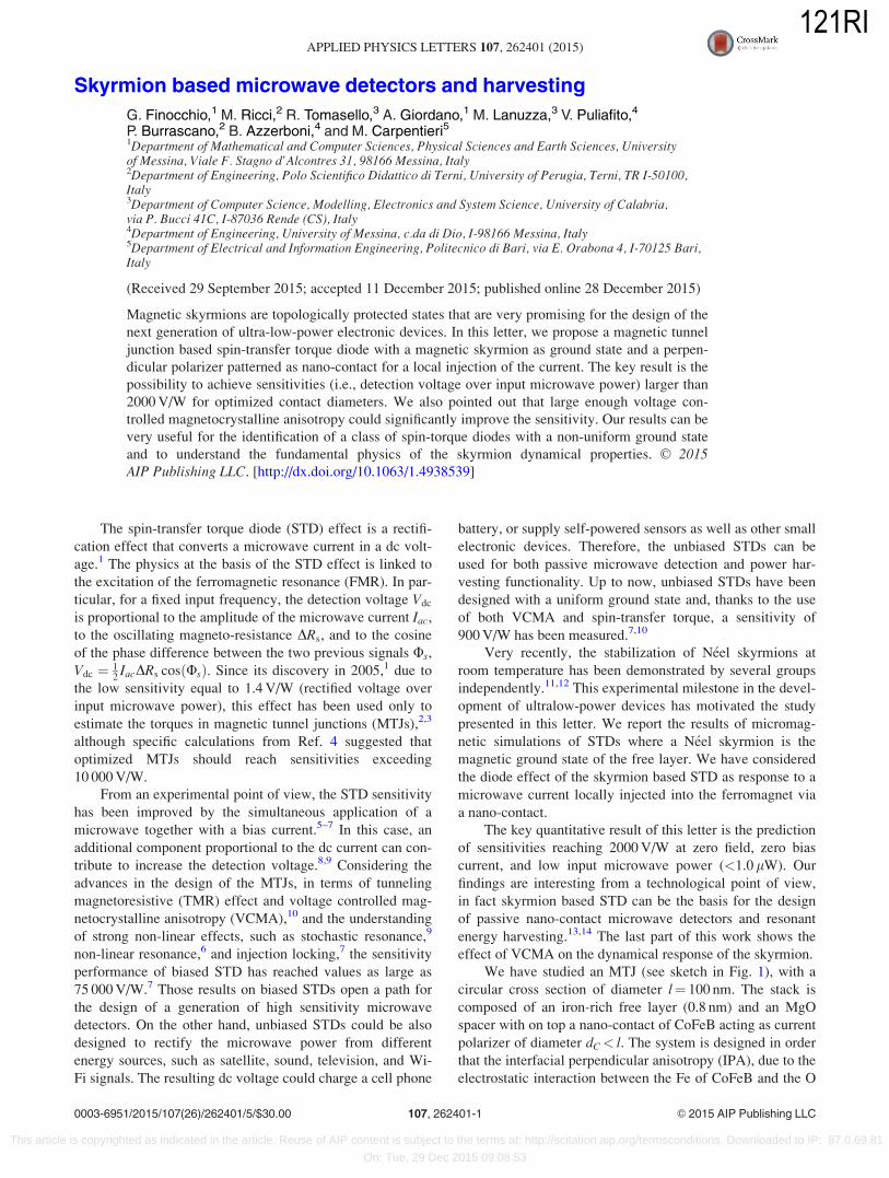
We have studied an MTJ (see sketch in Fig. 1), with a
circular cross section of diameter l¼ 100 nm. The stack is
composed of an iron-rich free layer (0.8 nm) and an MgO
spacer with on top a nano-contact of CoFeB acting as current
polarizer of diameter dC< l. The system is designed in order
that the interfacial perpendicular anisotropy (IPA), due to the
electrostatic interaction between the Fe of CoFeB and the O
0003-6951/2015/107(26)/262401/5/$30.00 VC 2015 AIP Publishing LLC107, 262401-1
APPLIED PHYSICS LETTERS 107, 262401 (2015)
This article is copyrighted as indicated in the article. Reuse of AIP content is subject to the terms at: http://scitation.aip.org/termsconditions. Downloaded to IP: 87.0.69.81
On: Tue, 29 Dec 2015 09:08:53
121RI
of MgO, is large enough to induce an out of plane easy axis
(z-axis) in both ferromagnets.15 Furthermore, the free layer
is coupled to a Pt layer to introduce in its energy landscape
an additional degree of freedom due to the interfacial
Dzyaloshinskii-Moriya Interaction (i-DMI) given by
eDMI ¼ 2D½mzr �m� ðm � rÞmz�; (1)
where m is the normalized magnetization vector of the free
layer and mz is its z-component.16 Basically, the effective
field of the free layer takes into account, together with the
standard micromagnetic contributions of the exchange and
the self-magnetostatic fields, the IPA and the i-DMI fields.
All the results discussed in this letter are achieved at zero
external field. The main simulation parameters are saturation
magnetization MS¼ 0.9 MA/m, Gilbert damping aG¼ 0.03,
and exchange constant A¼ 20 pJ/m. We have performed
micromagnetic simulations based on the Landau-Lifshitz-
Gilbert (LLG) equation to study the stability and the dynami-
cal response of a single N�eel skyrmion as a function of the
IPA (kU represents the IPA constant) and of the i-DMI pa-
rameter D (see Refs. 17 and 18 for a complete numerical
description of the model).
The inset of Fig. 2(a) shows a snapshot of a skyrmion (the
arrows refer to the in-plane component of the magnetization,
while the color is linked to its out-of-plane component—blue
negative and red positive) as ground state of the free layer,
where also its diameter dSK is indicated (the radius is calcu-
lated as the distance from the geometrical center of the sky-
rmion, where the out-of-plane component of the magnetization
mZ is �1, to the region where mZ¼ 0). The main panel of Fig.
2(a) shows the profile of mZ as computed by considering the
section AA0. The negative region coincides with the skyrmion
core, while the non-monotonic behavior near the edges is due
to the boundary conditions in presence of the i-DMI dmdn ¼
1n z � nð Þ �m (where n ¼ 2A
D is a characteristic length in pres-
ence of DMI and n is the direction normal to the surface).19
For the nucleation of the skyrmion, we apply a localized dc
spin-polarized current following the same procedure described
in Ref. 20, finding that the nucleation in a time smaller than
5 ns is achieved with bias current J¼ 30 MA/cm2.
Figures 2(b) and 2(c) show the skyrmion diameter dSK
as a function of D for two values of kU¼ 0.8 and 0.9 MJ/m3
and as a function of kU for D¼ 3.0 and 3.5 mJ/m2, respec-
tively. In our study, we have used DMI parameters larger
than the one estimated in state of the art of materials
(> 2.0 mJ/m2 for a ferromagnetic thickness of 0.8 nm).21–23
However, ab initio computations have predicted values of Dclose to 3.0 mJ/m2 for Pt/Co bilayers.24 In addition, this
choice can permit to have a comparison with previous nu-
merical studies.25 The fixed layer diameter dC, which also
corresponds to the nano-contact size, has been chosen to be
comparable or larger than the skyrmion diameter. This as-
pect is important to design the skyrmion based microwave
detector in order to optimize its sensitivity as it will be dis-
cussed below. To study the microwave dynamical properties,
we have considered both the Slonczewski and the field-like
torque as additional terms to the LLG equation
g jlBjJjejc0 M2
s tgT m;mpð Þ m� m�mpð Þ � q Vð Þ m�mpð Þ
h i;
(2)
where g is the gyromagnetic splitting factor, c0 is the gyro-
magnetic ratio, lB is the Bohr magneton, qðVÞ is a term
which takes into account the voltage-dependence of the field
like torque (see Refs. 26 and 27 for more numerical details),
J ¼ JM sinðxtÞ is the microwave current density, t is the
thickness of the free layer, e is the electron charge, and mp is
the normalized magnetization of the polarizer fixed along the
positive z-axis. gTðm;mpÞ ¼ 2gTð1þ gT2m �mpÞ�1
is the
polarization function.28,29 We have used for the spin-
polarization gT the value 0.66.2 Numerically, the resistance
of the device R is given by R ¼ RP þ ðRAP � RPÞð1� hmziÞbeing the polarizer aligned along the positive z-axis, while
RAP and RP are the resistances in the antiparallel and paral-
lel state, respectively. Within the approximation that the
direction of the magnetization changes sharply from down
(�1) to up (þ1) when moving across a skyrmion, R can
be estimated directly from the skyrmion diameter dSK as
follow:
R ¼ RP 1�d2
SK
d2C
!þ RAP
d2SK
d2C
; dSK< dC
RAP; dSK� dC;
8><>: (3)
for dSK< dC the left (right) contribution is related to the
micromagnetic cells below the nanocontact where mz > 0
(mz < 0).
To characterize the dynamical response of the STD, we
have also used the detection sensitivity e computed as the ra-
tio between the detection voltage and the input microwave
power (Pin) e ¼ Vdc
Pin. Pin is the active power delivered to the
MTJ, computed as Pin ¼ 0:5J2MS2R, being R the static resist-
ance (see Eq. (3)) and S the contact area.
Figures 3(a) and 3(b) show the STD response as a func-
tion of the microwave frequency (dC¼ 40 nm) achieved for
JM ¼ 3 MA/cm2, in (a) kU¼ 0.8 MJ/m3 is maintained fixed
while D¼ 2.5, 3.0, 3.5, and 4.0 mJ/m2, and in (b) D¼ 3.0 mJ/m2 while kU changes from 0.7 MJ/m3 to 0.9 MJ/m3.
The skyrmion response is mainly characterized by the excita-
tion of a breathing mode of its core, with a preserved radial
symmetry, similarly to the uniform breathing mode described
FIG. 1. Sketch of the device under investigation. The extended CoFeB acts
as free layer, while the top nano-contact made by CoFeB is the current po-
larizer (dC is the contact diameter, l¼ 100 nm). The Pt layer is necessary to
introduce the i-DMI.
262401-2 Finocchio et al. Appl. Phys. Lett. 107, 262401 (2015)
This article is copyrighted as indicated in the article. Reuse of AIP content is subject to the terms at: http://scitation.aip.org/termsconditions. Downloaded to IP: 87.0.69.81
On: Tue, 29 Dec 2015 09:08:53
121RI

in literature.25,30,31 The weak sinusoidal microwave current
(quasi-monochromatic signal) excites the uniform breathing
mode, being the skyrmion response in a quasi-linear regime.
This mode induces a resistance oscillation of amplitude DRs
linked to the minimum and maximum skyrmion core diameter
dSK-min and dSK-max and given by
DRS ¼RAP � RPð Þ
d2SK�max
� d2SK�min
d2C
dSK�max
< dC
RAP � RPð Þ 1�d2
SK�min
d2C
!d
SK�max� dC;
8>>>><>>>>:
(4)
DRS is as larger as d2SK�min� > 0 and d
SK�max� > dC. Moreover,
as expected, the ferromagnetic resonance frequency does not
change with the contact diameter dC (not shown), being linked
to the excitation of the uniform breathing mode of the sky-
rmion. An example of the time and space domain evolution of
the skyrmion core at the resonance frequency f¼ 4.6 GHz
(kU¼ 0.8 MJ/m3 and D¼ 3.0 mJ/m2) is shown in Ref. 32.
The FMR frequencies as a function of D for different kU
are summarized in Fig. 3(c). This non-monotonic trend can
be attributed to a different effect of the confining force (self-
magnetostatic field) on the skyrmion uniform breathing
mode. To qualitatively understand this behavior, we refer to
the concept of critical D (Dcrit) introduced in Ref. 19. For
extended ferromagnets, when D is below Dcrit, the confining
force is negligible, whereas for D near or above Dcrit, the con-
fining force plays a crucial role in fixing the skyrmion size.
We argue that this fact gives rise to the different slopes of the
FMR frequency vs D for our system. Those arguments are
confirmed by micromagnetic simulations performed for devi-
ces with diameter l¼ 75 nm and 150 nm (kU¼ 0.80 MJ/m3)
and displayed in Fig. 3(d). For l¼ 75 nm, the confining force
acts on the skyrmion also at small D giving rise to a mono-
tonic FMR frequency vs D curve. On the other hand, for
FIG. 2. (a) Profile of the out-of-plane component of the magnetization corresponding to the section AA0, as indicated in the inset. dsk represents the skyrmion
diameter. Inset: example of a snapshot of a N�eel skyrmion stabilized by the i-DMI, where the arrows indicate the in-plane component of the magnetization
while the colors are linked to the out-of-plane component (blue negative, red positive). (b) and (c) Skyrmion diameter as computed by means of micromagnetic
simulations (the radius is computed as the distance from the geometrical center of the skyrmion, where mZ¼�1, to the region where mZ¼ 0). Skyrmion diame-
ter (b) as a function of D for kU¼ 0.8 and 0.9 MJ/m3 and (c) as a function of kU for D¼ 3.0 and 3.5 mJ/m2.
FIG. 3. (a) STD response as a function
of D for kU¼ 0.8 MJ/m3. (b) STD
response as a function of kU for
D¼ 3.0 mJ/m2. (c) FMR frequency as
a function of D for two different values
of kU as indicated in the panel. (d)
FMR frequency as a function of D(kU¼ 0.8 MJ/m3) for three different
values of the cross section diameter
l¼ 75, 100, and 150 nm with the indi-
cation of the critical DMI parameter
Dcrit.
262401-3 Finocchio et al. Appl. Phys. Lett. 107, 262401 (2015)
This article is copyrighted as indicated in the article. Reuse of AIP content is subject to the terms at: http://scitation.aip.org/termsconditions. Downloaded to IP: 87.0.69.81
On: Tue, 29 Dec 2015 09:08:53
121RI

l¼ 150 nm the non-monotonic trend is exhibited again and
the minimum moves towards D¼Dcrit¼ 3.07 mJ/m2, as
expected.
To compare the skyrmion-based STD to the state-of-the-art MTJ-based STDs, we have performed a systematic study
of the sensitivity computed at the FMR frequency as a func-
tion of the dC (30 nm< dC< 60 nm). All the data discussed
below are obtained for kU¼ 0.8 MJ/m3 and D¼ 3.0 mJ/m2;
however, qualitative similar results have been achieved for
kU¼ 0.9 MJ/m3 and D¼ 2.5 and 3.5 mJ/m2.
Fig. 4(a) summarizes the sensitivities computed for four
different current amplitudes JM ¼ 1�4 MA/cm2 maintained
constant at different dC (RAP¼ 1.5 kX and RP¼ 1 kX).33 One
key finding is the existence of an optimal contact size where
the sensitivity exhibits a maximum value. This result can be
qualitatively understood as follow. For a fixed skyrmion
ground state, the change in the dC introduces a change in the
microwave power (both static resistance R and contact cross
section depend on dC). Fig. 4(b) displays the detection volt-
age and the input microwave power as a function of the con-
tact size for JM¼ 1 MA/cm2. As can be observed, both the
detection voltage and the input microwave power increase as
a function of dC. Their ratio determines the optimal dC, as
reported in Fig. 4(a). In particular, the key condition to be
fulfilled is
ded dcð Þ
¼ 1
P2in
Pin
dVdc
d dcð Þ� Vdc
dPin
d dcð Þ
� �¼ 0; (5)
which should be solved numerically. The second result is the
prediction, for an optimal configuration, of sensitivities of the
order of 2000 V/W, which are larger than the ones of state ofthe art unbiased MTJ-based STDs around 900 V/W.7,10
Fig. 4(c) summarizes the sensitivities computed as a
function of the dC for different values of the microwave
power. Those computations also show the existence of an
optimal contact, which coincides with the maximum of the
detection voltage, as summarized in Fig. 4(d). In fact, for the
last computational framework, the Eq. (6) holdsde
dðdcÞ ¼dVdc
dðdcÞ ¼ 0. As can be observed, the two maxima differ
by less than 5 nm (compare Figs. 4(a) and 4(c)).
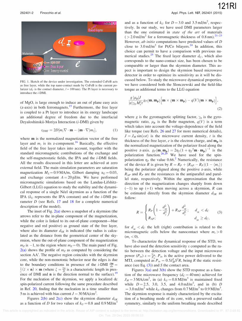
The last part of the letter investigates a possible contribu-
tion of the VCMA to the sensitivity of skyrmion based
STDs.34 We have implemented this contribution as an additive
field to the effective field as HVCMA ¼ DHVCMA sinðxtÞapplied along the out-of-plane direction.35 In CoFeB/MgO/
CoFeB stacks, the VCMA has been already used to demon-
strate the electrical field assisted switching36 and to improve
the sensitivity of unbiased STDs.7,10 We have performed an
ideal numerical experiment considering the optimal scenario
of Fig. 4(a) (dC¼ 40 nm, FMR frequency � 4.6 GHz). At
JM ¼ 0 MA/cm2, the HVCMA drives an oscillating z-
component of the magnetization whose amplitude as a func-
tion of DHVCMA is displayed in Fig. 5(a). The key difference
with parametric resonance is the absence of a threshold value
for the excitation of dynamics. In other words, the VCMA
acts on a skyrmion state as linear excitation.35 Fig. 5(b) shows
the sensitivities as a function of the DHVCMA for JM¼ 1 and
2 MA/cm2. The minimum in the sensitivity around
DHVCMA¼ 4 mT can be explained by the change in the phase
Us (see Fig. 5(c)). While the amplitude of the DRS monotoni-
cally increases with the DHVCMA, the Us is non-monotonic:
firstly it decreases up to a minimum value at DHVCMA¼ 4 mT
(Us¼ 0.66p for JM¼ 1 MA/cm2) and then increases. An in-
depth analysis of the micromagnetic configurations shows
that at low DHVCMA both dSK�min
and dSK�max
change (dSK�min
decreases and dSK�max
increases). On the other hand, as the
DHVCMA increases, it exists a critical value at which the
dSK�max
saturates to dC, while dSK�min
will continue to decrease.
In this way, DRS (see Eq. (4)) and, consequently, Vdc
increase, proving that the presence of a large enough VCMA
effect can significantly improve the sensitivity of the sky-
rmion based STD.
To estimate the VCMA contribution, we consider the
optimal case of Fig. 4(a), JM¼ 1 MA/cm2 and a typical
FIG. 4. (a) Sensitivity as a function of
the contact diameter for different
amplitudes of the microwave current
as indicated in the main panel. (b)
Detection voltage and microwave
power as a function of the contact di-
ameter for JM ¼ 1 MA/cm2. (c)
Sensitivity as a function of the contact
diameter for different microwave
powers as indicated in the main panel.
In both (a) and (c), an optimal contact
diameter corresponding to a maximum
in the sensitivity can be observed. (d)
Detection voltage as a function of the
contact diameter for different micro-
wave powers. All the data reported in
this figure are obtained for
kU¼ 0.8 MJ/m3 and D¼ 3.0 mJ/m2.
262401-4 Finocchio et al. Appl. Phys. Lett. 107, 262401 (2015)
This article is copyrighted as indicated in the article. Reuse of AIP content is subject to the terms at: http://scitation.aip.org/termsconditions. Downloaded to IP: 87.0.69.81
On: Tue, 29 Dec 2015 09:08:53
121RI
experimental VCMA value of 60 mT/V.10 However, by using
state of the art values of VCMA, the DHVCMA � 1 mT would
result negligible giving rise to a negligible effect in our
devices.
In summary, we have proposed a zero field and an
unbiased skyrmion based STD for passive microwave detec-
tion and energy harvesting application. The skyrmion is sta-
bilized by the i-DMI and when it is supplied by a microwave
spin current with perpendicular polarization, a breathing
mode is excited. The change in the size of the skyrmion is
converted to a change of the TMR signal, which gives rise to
a detection voltage. We have pointed out that sensitivities as
large as 2000 V/W can be achieved for optimized contact di-
ameter. Our results open a path for fundamental physics in
understanding the skyrmion dynamical properties and for the
design of STD with a non-uniform ground state.
This work was supported by the project PRIN2010ECA8P3
from Italian MIUR. The work of G.F. and M.C. was also
supported by the bilateral agreement Italy-Turkey project
(Code B52I14002910005) “Nanoscale magnetic devices
based on the coupling of Spintronics and Spinorbitronics.”
The authors thank Domenico Romolo for the support in
making Figure 1. M.R. and P.B. acknowledge financial
support from Fondazione CARIT - Progetto Sensori
Spintronici.
1A. A. Tulapurkar, Y. Suzuki, A. Fukushima, H. Kubota, H. Maehara, K.
Tsunekawa, D. D. Djayaprawira, N. Watanabe, and S. Yuasa, Nature 438,
339–342 (2005).2J. C. Sankey, Y.-T. Cui, J. Z. Sun, J. C. Slonczewski, R. A. Buhrman, and
D. C. Ralph, Nat. Phys. 4, 67–71 (2008).3H. Kubota, A. Fukushima, K. Yakushiji, T. Nagahama, S. Yuasa, K.
Ando, H. Maehara, Y. Nagamine, K. Tsunekawa, D. D. Djayaprawira
et al., Nat. Phys. 4, 37–41 (2008).4C. Wang, Y.-T. Cui, J. Z. Sun, J. A. Katine, R. A. Buhrman, and D. C.
Ralph, J. Appl. Phys. 106, 053905 (2009).5X. Cheng, C. T. Boone, J. Zhu, and I. N. Krivorotov, Phys. Rev. Lett. 105,
047202 (2010).6S. Miwa, S. Ishibashi, H. Tomita, T. Nozaki, E. Tamura, K. Ando, N.
Mizuochi, T. Saruya, H. Kubota, K. Yakushiji et al., Nat. Mater. 13,
50–56 (2014).7B. Fang, M. Carpentieri, X. Hao, H. Jiang, J. A. Katine, I. N. Krivorotov,
B. Ocker, J. Langer, K. L. Wang, B. Zhang et al., e-print arXiv:1410.4958.8G. Finocchio, I. N. Krivorotov, X. Cheng, L. Torres, and B. Azzerboni,
Phys. Rev. B 83, 134402 (2011).9X. Cheng, J. A. Katine, G. Rowlands, and I. N. Krivorotov, Appl. Phys.
Lett. 103, 082402 (2013).
10J. Zhu, J. A. Katine, G. E. Rowlands, Y.-J. Chen, Z. Duan, J. G. Alzate, P.
Upadhyaya, J. Langer, P. K. Amiri, K. L. Wang et al., Phys. Rev. Lett.
108, 197203 (2012).11C. Moreau-Luchaire, C. Moutafis, N. Reyren, J. Sampaio, N. Van Horne,
C. A. F. Vaz, K. Bouzehouane, K. Garcia, C. Deranlot, P. Warnicke et al..e-print arXiv:1502.07853.
12S. Woo, K. Litzius, B. Kr€uger, M.-Y. Im, L. Caretta, K. Richter, M. Mann,
A. Krone, R. Reeve, M. Weigand et al., e-print arXiv:1502.07376.13S. Hemour and K. Wu, Proc. IEEE 102, 1668–1691 (2015).14A. M. Hawkes, A. R. Katko, and S. A. Cummer, Appl. Phys. Lett. 103,
163901 (2013).15S. Ikeda, K. Miura, H. Yamamoto, K. Mizunuma, H. D. Gan, M. Endo, S.
Kanai, J. Hayakawa, F. Matsukura, and H. Ohno, Nat. Mater. 9, 721–724
(2010).16T. Moriya, Phys. Rev. Lett. 4, 228 (1960).17R. Tomasello, E. Martinez, R. Zivieri, L. Torres, M. Carpentieri, and G.
Finocchio, Sci. Rep. 4, 6784 (2014).18R. Tomasello, M. Carpentieri, and G. Finocchio, J. Appl. Phys. 115,
17C730 (2014).19S. Rohart and A. Thiaville, Phys. Rev. B 88, 184422 (2013).20J. Sampaio, V. Cros, S. Rohart, A. Thiaville, and A. Fert, Nat.
Nanotechnol. 8, 839 (2013).21M. Belmeguenai, J.-P. Adam, Y. Roussign�e, S. Eimer, T. Devolder, J.-V.
Kim, S. M. Cherif, A. Stashkevich, and A. Thiaville, Phys. Rev. B 91,
180405(R) (2015).22J. Cho, N.-H. Kim, S. Lee, J.-S. Kim, R. Lavrijsen, A. Solignac, Y. Yin,
D.-S. Han, N. J. J. van Hoof, H. J. M. Swagten et al., Nat. Commun. 6,
7635 (2015).23S. Pizzini, J. Vogel, S. Rohart, L. D. Buda-Prejbeanu, E. Ju�e, O. Boulle,
I. M. Miron, C. K. Safeer, S. Auffret, G. Gaudin et al., Phys. Rev. Lett.
113, 047203 (2014).24H. Yang, A. Thiaville, S. Rohart, A. Fert, and M. Chshiev, e-print
arXiv:1501.05511v1.25J.-V. Kim, F. Garcia-Sanchez, J. Sampaio, C. Moreau-Luchaire, V. Cros,
and A. Fert, Phys. Rev. B 90, 064410 (2014).26G. Finocchio, B. Azzerboni, G. D. Fuchs, R. A. Buhrman, and L. Torres,
J. Appl. Phys. 101, 063914 (2007).27Z. Zeng, G. Finocchio, B. Zhang, P. K. Amiri, J. A. Katine, I. N.
Krivorotov, Y. Huai, J. Langer, B. Azzerboni, K. L. Wang et al., Sci. Rep.
3, 1426 (2013).28J. C. Slonczewski, Phys. Rev. B 71, 024411 (2005); J. C. Slonczewski and
J. Z. Sun, J. Magn. Magn. Mater. 310, 169–175 (2007).29A. Giordano, G. Finocchio, L. Torres, M. Carpentieri, and B. Azzerboni,
J. Appl. Phys. 111, 07D112 (2012).30S.-Z. Lin, C. D. Batista, and A. Saxena, Phys. Rev. B 89, 024415 (2014).31C. Schutte and M. Garst, Phys. Rev. B 90, 094423 (2014).32See supplementary material at http://dx.doi.org/10.1063/1.4938539 for a
video of the spin-dynamics at resonant frequency.33H. Meng, R. Sbiaa, M. A. K. Akhtar, R. S. Liu, V. B. Naik, and C. C.
Wang, Appl. Phys. Lett. 100, 122405 (2012).34T. Maruyama, Y. Shiota, T. Nozaki, K. Ohta, N. Toda, M. Mizuguchi, A.
A. Tulapurkar, T. Shinjo, M. Shiraishi, S. Mizukami et al., Nat.
Nanotechnol. 4, 158–161 (2009).35R. Verba, V. Tiberkevich, I. Krivorotov, and A. Slavin, Phys. Rev. Appl.
1, 044006 (2014).36W. G. Wang, M. Li, S. Hageman, and C. L. Chien, Nat. Mater. 11, 64–68
(2012).
FIG. 5. (a) Amplitude of the z-component of the magnetization driven by DHVCMA at JM ¼ 0 MA/cm2; (b) sensitivity as a function of the DHVCMA, considering
the optimal contact diameter of Fig. 4(a) (dC¼ 40 nm), computed for JM ¼ 1 and 2 MA/cm2. (c) Phase shift Us as a function of DHVCMA for the same micro-
wave currents amplitudes of (b).
262401-5 Finocchio et al. Appl. Phys. Lett. 107, 262401 (2015)
This article is copyrighted as indicated in the article. Reuse of AIP content is subject to the terms at: http://scitation.aip.org/termsconditions. Downloaded to IP: 87.0.69.81
On: Tue, 29 Dec 2015 09:08:53
121RI