Embed Size (px)
Citation preview

Because sound matters
Oticon Medical is a global company in implantable hearing solutions, dedicated to bringing the magical world of sound to people at every stage of life. As a member of one of the world’s largest groups of hearing health care companies, we share a close link with Oticon and direct access to the latest advancements in hearing research and technologies. Our competencies span more than a century of innovations in sound processing and decades of pioneering experience in hearing implant technology.
By working collaboratively with patients, physicians and hearing care professionals, we ensure that every solution we create is designed with user needs in mind. We share an unwavering commitment to providing innovative solutions and support that enhance quality of life for people wherever life may take them. Because we know how much sound matters.
1754
65U
K /
2016
.10
www.oticonmedical.com
Manufacturer:Oticon Medical AB Datavägen 37B SE-436 32 AskimSweden Phone: +46 31 748 61 00 Email: [email protected]
Because sound matters
Skull simulator Guide

CONTENTS CONTENTS3 4
Contents
Introduction .................................................................................................5How does a Skull simulator work? ............................................................5Clinical application .................................................................................7
Verification ................................................................................................. 9Prepare the sound processor for measurement ....................................... 9Place the sound processor on the Skull simulator ................................... 11Conduct measurement .......................................................................... 11Prepare for comparison of curves in Affinity and Genie Medical .............. 13Comparison of curves ............................................................................ 15If fine-tuning in Genie Medical is needed ............................................... 17
Technical measurements ............................................................................19Introduction to technical measurements ................................................19Technical measurement using pure tones ...............................................21Comparison of curves ............................................................................23Standardised measurements .................................................................25
How to get started......................................................................................27Installation ...........................................................................................27Licence ................................................................................................ 29Activating the new HIT Licence ...............................................................31Setup Affinity ........................................................................................31Set up Skull simulator ...........................................................................33Placement of the bone anchored sound processor .................................35Set up Genie Medical ............................................................................37
How to create a protocol in Affinity ............................................................ 39How to export and import a test protocol in the HIT module ........................41
INTRODUCTION INTRODUCTION5 6
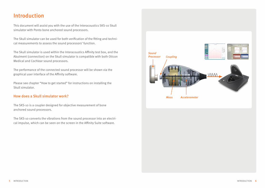
Sound Processor Coupling
Mass Accelerometer
Introduction
This document will assist you with the use of the Interacoustics SKS-10 Skull simulator with Ponto bone anchored sound processors.
The Skull simulator can be used for both verification of the fitting and techni-cal measurements to assess the sound processors’ function.
The Skull simulator is used within the Interacoustics Affinity test box, and the Abutment (connection) on the Skull simulator is compatible with both Oticon Medical and Cochlear sound processors.
The performance of the connected sound processor will be shown via the graphical user interface of the Affinity software.
Please see chapter “How to get started” for instructions on installing the Skull simulator.
How does a Skull simulator work?
The SKS-10 is a coupler designed for objective measurement of bone anchored sound processors.
The SKS-10 converts the vibrations from the sound processor into an electri-cal impulse, which can be seen on the screen in the Affinity Suite software.

INTRODUCTION INTRODUCTION7 8
Clinical application
The SKS-10 can be applied at several different points during the patient’s rehabilitation process.
• Pre-operative trial: to assist in the confirmation of the sound processor performance between patients
• Fitting: to help clinicians verify the fitting
• Post-fitting: to confirm the correct function of the sound processor and assist in the decision-making process regarding possible repair
In each scenario the Skull simulator is used to give an objective, un-opinion-ated, view of the sound processor’s performance and the accuracy of the fitting.
Pre-operative trial Fitting Post-fitting

VERIFICATION VERIFICATION9 10
The automatic settings should match the test signal. For more information, Click to access the Help files.
Automatic settings for:
Pure tone Speech signal
NM: Noise ManagementAD: Automatic DirectionalityDFC: Dynamic Feedback CancellationVCL: Learning Volume Control
Verification
When fitting the Ponto, use the SKS-10 to verify that the measured output of the sound processor matches the target curve in Genie Medical.
The starting point for obtaining an accurate, individual prescribed target is to conduct a BC In-situ measurement in Genie Medical.
Importing the predefined protocol for Verification to Affinity will assist and ease the verification procedure; please see chapter “How to import a proto-col to Affinity” for further information.
Prepare the sound processor for measurement
a. Connect and fit the sound processor in Genie Medical
b. Go to Fitting step → Verification Tool → see (Fig. 1)
If Genie Medical is run through NOAH when you enter the Verification tool, the Affinity software will launch automatically.
c. Affinity will open up in the REM module. Click OK in the Fitting prescription settings dialog → click HIT on the upper right (Fig. 2) to access the Hearing Instrument Test (HIT) module
d. Go to Genie Medical screen
e. Turn on/off Automatics → see (Fig. 3)
All boxes for automatic settings in the Verification tool should be un-checked and thereby deactivated when using pure tones.
Figure 1. Verification tool
Figure 2. Access the HIT module in the top-right corner
Figure 3. Settings for Automatics

VERIFICATION VERIFICATION11 12
1
2
3
4
Figure 4. Affinity screen
Figure 5. Placement of Ponto on the Skull simulator
Place the sound processor on the Skull simulator
Place the sound processor on the SKS-10 abutment. → See (section Placement of the Skull simulator for additional information).
Note: the connection cord to the sound processor can remain connected when the lid is shut.
Conduct measurement
Go to Affinity screen → see (Fig. 4)a. Select Ear (L/R) (1)
b. Choose the Verification protocol, or your own protocol (2)
c. Choose Signal (Pure Tone or your preferred signal) (3)
d. Press Start to run your measurements (4)
Before running the measurement, check the positioning of the sound processor on the Skull simulator and close the test box lid → see (Fig. 5)

VERIFICATION VERIFICATION13 14
Figure 6. Prepare for curve comparison in Affinity
Prepare for comparison of graphs in Affinity and Genie Medical
In Affinity screen → see (Fig. 6)
a. Click on the curve you want to display in the protocol, e.g. Frequency Response 70 (1)
b. Go back to Genie Medical screen → Verification tool
c. Ensure that the Signal type and Input levels correspond to what you have measured in Affinity
d. Click floating graph
e. Position the Genie Medical screen and Affinity screen beside each other for easy curve comparison

VERIFICATION VERIFICATION15 16
Comparison of curves
a. Go to Genie Medical screen → Verification tool → see (Fig. 1, page 10)
b. Select curve Target 70 → see (Fig. 7)
c. Compare this curve with Frequency Response 70 in Affinity → see (Fig 6, page 14)
d. Continue comparing Target 50 in Genie Medical with Frequency Response 50 in Affinity screen and Target 90 with Frequency Response 90
e. Evaluate if the measured curve in Affinity has the same curve configuration as the target curve in Genie Medical
f. Evaluate if the measured curve in Affinity reaches the same output level as the target curve in Genie Medical, ideally within ±3-5 dB
Figure 7. Output curves in Verification tool
Curve type; Output, Skull
Signal type; Pure/Warble Tone
Input levels; 50, 70- and 90 dB µN
The default settings in Verification tool are:
Tips box for default settings
Tips box for comparable speech-shaped signals
Genie Medical AffinityANSI S3.42 Pseudo Random NoiseICRA stationary (ANSI S3.5) ICRA: Urgnmn
The following speech-shaped signals are comparable:

VERIFICATION VERIFICATION17 18
1. Click on the list Current session to open a previous session
• Click to lock the sessions to the screen
2. Perform your measurement or compare to a previous measured curve
3. Click to unlock the session
4. Click to go back to current session
It is possible to compare your current measurement with a previous one:
Figure 8. Measured curves in Affinity
Tips box for comparison of curves between current and previous measurements
If fine-tuning in Genie Medical is needed:
a. Go to Verification tool → see (Fig 1., page 10)
b. Adjust controls to fine-tune
c. Go back to Affinity
d. Perform a new measurement → see Section “Conduct measurement”
e. The second measured curve (2) will now appear in the same graph as the first measured curve (1) → see (Fig. 8)
f. All fine-tuning is retained when you close the verification tool, and can then be saved to the sound processor in the end fitting step
1
2

TECHNICAL MEASUREMENTS TECHNICAL MEASUREMENTS19 20
Technical measurement
Introduction to technical measurements
Technical measurement helps you evaluate the technical performance of the Ponto sound processor. This can be helpful at listed fittings steps:
• Before the next potential patients gets it
• During the fitting, to get a reference curve to compare later on
• After the fitting, if the patient complains about the Ponto sound processor’s performance

TECHNICAL MEASUREMENTS TECHNICAL MEASUREMENTS21 22
1
2
1a
1b3
Figure 9. Access Technical tool via End Fitting → Tools → Technical Measurements
Figure 10. Technical tool
Technical Measurement using pure tones
When performing technical Measurement, make sure the client does not wear the sound processor during the test.
Importing the predefined protocol for Technical Measurement to Affinity will assist and ease the Technical Measurement procedure; please see chapter “How to Export and Import a test protocol in the HIT module”.
1. Connect the sound processor in Genie Medical.
2. Go to End Fitting → Tools see 1 (Fig. 9) → Technical Measurements See 2 (Fig. 9)
3. Choose the desired standard technical settings. See → 1a (Fig. 10)
4. Program the desired standard technical setting to the sound processor. See → 1b (Fig. 10)
5. Click on Open HIT Module to launch the Affinity HIT software. See → 2 (Fig. 10)
Go back to Affinity screen → See (Fig. 4, page 12) a. Select Ear (L/R) b. Choose the Technical protocol c. Choose Signal (pure tone or speech signal) d. Control positioning of the sound processor on the Skull simulator See → (Fig. 5, page 12) e. Press Start to run your measurements

TECHNICAL MEASUREMENTS TECHNICAL MEASUREMENTS23 24
Comparison of curves
Measured curves can be compared to graphs in Genie Medical. See → (Fig. 11)a. For comparison with graphs in Genie Medical, follow the steps in sections →
“Prepare for comparison of curves in Affinity and Genie Medical” and “Comparison of curves”
b. Make sure the measured curves are measured with the same signal type and output level as the one with which it is compared
• Do not allow the client to listen to sound processors with technical settings. The user settings must be restored to the sound processor
• If the tool was accidently closed before user settings were programmed into the sound processor, attach the cable and click Connect in Genie Medical. If the sound processor contains technical settings, Genie Medical automatically restores the user settings
If the sound processor is disconnected while in the Technical tool, Technical settings are stored in the local memory of the sound processor.
Curve type; Gain, Skull
Signal type; Pure/Warble Tone
Input levels; 50, 65- and 80 dB µN
The default settings in Technical tool are:
Figure 11. Output curves in Technical Tool
Tips box default setting in Technical Tool

TECHNICAL MEASUREMENTS TECHNICAL MEASUREMENTS25 26
5
Figure 12. Standardised measurement, in this example harmonic distortion
Standardised measurements
The standardised measurements Battery Current Drain (1), Harmonic Distortion (2), Equivalent input noise (3) and Processing delay (4) are included in the Technical measurement protocol.
a. Go back to Affinity screen
b. Click on the measurement you would like to evaluate, i.e. Harmonic Distortion (2)
c. The technical information on harmonic distortion will then show on the right side of the screen
d. Compare those values to values in the product information1234

HOW TO GET STARTED HOW TO GET STARTED27 28
How to get started
Installation
To prepare the Affinity for use with the SKS-10, you will require the following items:
• The Affinity 2.0 hardware
• The Interacoustics SKS10 Skull simulator and its power supply
• The HIT440 software licence
• The SKS10 Skull simulator licence
This section of the guide will take you through how to correctly licence and begin using the Skull simulator within the Affinity Suite.

HOW TO GET STARTED HOW TO GET STARTED29 30
Figure 13. Copy licence
Licence
If you have purchased an Affinity that has already got the functionality for the Skull simulator pre-configured then you can skip this step.
If you have owned your Affinity for a while and wish to add the Skull simulator functionality then please follow these instructions.
a. After purchasing a Skull simulator and a Skull simulator licence, please send Interacoustics ([email protected]) the serial number
To copy the serial number, go to Menu/Help/About, click on Licence and select “Copy s/n”; this will copy the serial number to the Clipboard See → (Fig. 13)
b. Paste the serial number in the body of an e-mail and mail it to Interacoustics
c. Interacoustics will then e-mail a new HIT licence

HOW TO GET STARTED HOW TO GET STARTED31 32
Figure 14. Paste licence
Figure 15. General settings
Activating the new HIT licence
a. Go to HIT module/Menu/Help/About
b. Click on Licence
c. Paste the new licence number under HIT/New licence see (Fig. 14)
Setup Affinity
When starting your Affinity for the first time, you will need to enable the Skull simulator; please follow the instructions below to enable this.
a. Go to HIT/Menu/Setup/HIT440 setup → see (Fig. 14)
b. Choose “Skull simulator” or your preferred protocol under “Selected Protocols”
c. Under “General Settings”, ensure that “Skull simulator” is chosen under “Coupler” → see (Fig. 15)

HOW TO GET STARTED HOW TO GET STARTED33 34
Figure 15. Set up Skull simulator
Set up Skull simulator
The SKS-10 requires an external power supply for it to operate correctly. Ensure that this is connected to the sound processor ahead of performing any measurements.
Once connected, the SKS-10 should be positioned in the test box → see (Fig. 15). This ensures that the abutment is at the reference point marked by a cross in the floor of the Affinity test box. In this position, it is easier to align the Affinity reference microphone closer to your Sound Processor’s micro-phones once it has been connected to the Skull simulator.
All of this information is given in the software on loading the Skull simulator protocol. It can be seen in the form of a pop-up → see (Fig. 15).
This pop-up can be deactivated by inserting a checkmark in the “Do not show this setup guide again” box.
To re-initiate the Skull Coupler Setup Guide startup window, go to Menu/Setup/General Setup and insert a checkmark in the “Show setup guide” box.

HOW TO GET STARTED HOW TO GET STARTED35 36
Placement of bone anchored sound processor
It may be required that you leave the test box lid open approximately 1 centimetre when performing certain measurements. The protocol should alert you of when to open this. Leaving the box ajar improves the quality of the measurement.
Skull simulator placement and reference point (marked by the cross)
Bone anchored hearing sound processor connected to the Skull simulator at reference point

HOW TO GET STARTED HOW TO GET STARTED37 38
Figure 18. Access the Verification tool from the Fitting step
Figure 19. Access the Technical measurement tool from the end fitting step
Setup Genie Medical
In Genie Medical, use the Verification tool and the Technical tool when you perform your measurements. The Verification tool can be launched from the fitting step → see (Fig. 18) and the Technical tool can be launched from the end fitting step → see (Fig. 19).
Hence, while using the Verification tool, one cannot go directly to the Techni-cal tool.
Use the verification tool when performing verification measurements and the technical tool when performing technical measurements.

HOW TO CREATE A PROTOCOL IN AFFINITY HOW TO CREATE A PROTOCOL IN AFFINITY39 40
How to create a protocol in Affinity
Please see the Quick Guide – HIT440 Protocol Setup found on the Interacous-tics homepage.
Quick guide on how to create or edit protocols in the Affinity software
Please scan the QR Code to acces the Quick Guide on the Interacoustics homepage

HOW TO EXPORT AND IMPORT A TEST PROTOCOL IN THE HIT MODULE41 42HOW TO EXPORT AND IMPORT A TEST PROTOCOL IN THE HIT MODULE
Figure 20.
How to export and import a test protocol in the HIT module
Export a protocol1. Launch your Interacoustics Software suite as usual
2. Go into the HIT module
3. Go into Menu > Setup > HIT440 Setup
4. The screen will then be shown (Fig. 20)
5. Use the Selected Protocol drop-down menu to select the protocol you wish to export. Note: a pop-up will appear on doing this, asking if you want to “save as read only”. If yes is selected then the protocol cannot to be edited or modified when imported into the software
6. Next, click on the Export button and specify the location where you wish to save it. This file can then be copied to a USB thumb drive or e-mailed to allow sharing between systems.
HOW TO EXPORT AND IMPORT A TEST PROTOCOL IN THE HIT MODULE43 44HOW TO EXPORT AND IMPORT A TEST PROTOCOL IN THE HIT MODULE
How to export and import a test protocol in the HIT module
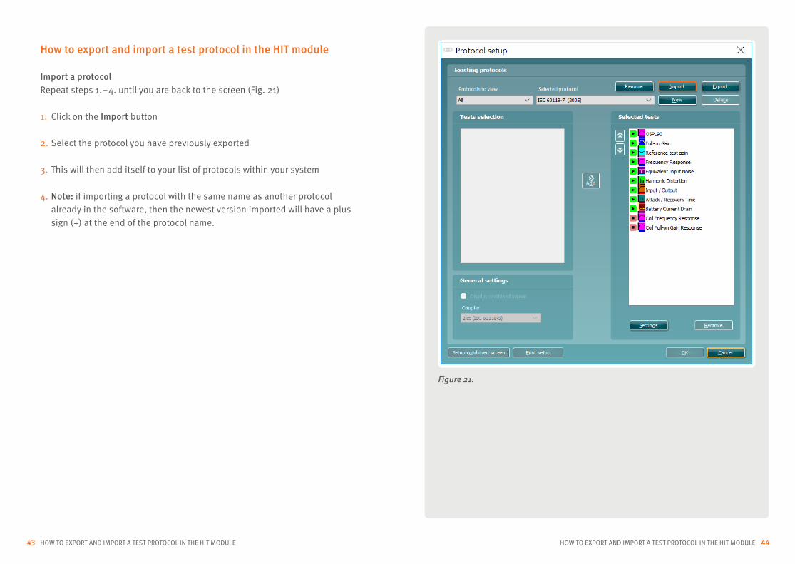
Import a protocolRepeat steps 1. – 4. until you are back to the screen (Fig. 21)
1. Click on the Import button
2. Select the protocol you have previously exported
3. This will then add itself to your list of protocols within your system
4. Note: if importing a protocol with the same name as another protocol already in the software, then the newest version imported will have a plus sign (+) at the end of the protocol name.
Figure 21.