Embed Size (px)
Citation preview

SKIRTED SPUDCAN- SOIL INTERACTION UNDER COMBINED LOADING - GAP CONDITIONS
AFTER PRELOADING
L. Kellezi*, O. Koreta and S. S. Sundararajan
Geo, Copenhagen, Denmark
*corresponding author: Lindita Kellezi: [email protected]
ABSTRACT
When a jack-up rig, equipped with skirted spudcans, is installed on competent seabed soil, limited penetrations
(less than full base contact) can be experienced. In such a case, there are limitations in the existing guidelines with
regard to the calculations of (V-H-M) capacity based on the conventional methods. In this paper, for a jack-up rig
installed in the North Sea, experiencing penetrations less than full base contact, the assessment of footing-soil
system stability and stiffness under storm load conditions is carried out. Finite element (FE) analyses are carried
out by modelling the spudcan in 2D and in 3D (allowing for accurate modelling of the inner skirts). Due to the gap
presence, large deformation, updated mesh (UM) analyses are carried out in order to account for increased (V-H-
M) bearing capacity developed due to additional penetrations and gained contact area of the underside of the
spudcan and the seabed soil. Important conclusions are derived and recommendations given with regard to
identifying the governing failure mechanisms and predicting the behavior and capacity in the elevated conditions
of the skirted footings suffering limited penetrations during preloading.
KEY WORDS: skirted spudcans, (V-H-M) capacity, fixity analyses, limit equilibrium, finite element
INTRODUCTION
Jack-up rigs equipped with skirted spudcans are commonly used in the offshore industry. Some of the benefits of
the skirted footing include: improvement of the foundation capacity by increasing the effective depth of the
footing; improvement of the horizontal capacity by reducing the risk for sliding; improvement of the foundation
fixity and provision of protection from scour when that is expected to be a major issue.
a) Skirted spudcan penetrated to depth corresponding to
less than full base contact during preloading (V)
b) Approximate additional penetrations of skirted spudcan
under (V-H-M) loads, exceeding the yield capacity
derived based on the preload. The possibly gained
additional contact area is shown in red
Figure 1 Skirted spudcan penetrating to depth less than full base contact
The benefits of skirted spudcans are mentioned in the current industry guidelines such as: [1], [2], [3], [4].
However, very limited information is provided with regard to the design methods for predicting their capacity
under combined loading. For conditions when combined Vertical (V), Horizontal (H), and Moment (M) loading

apply, the conventional approach has shown to be less reliable. On this aspect, previous research studies have been
carried out by [5], [6], [7] using conventional, 2D and 3D FE analyses for skirted footings under combined loads,
considering multi-layered soil profiles (sand overlying clay with varying strength, sand overlying soft clay
followed by sand and stiff clay) and full base skirted spudcan penetrations. The studies have been based on real
industry projects / case histories and supported by feedback from the jack-up installations and operations. Other
aspects, such as applying suctions in order to increase the skirt penetration and (V-H-M) capacity are also
investigated in [7].
In specific sites, due to the special geometry of the skirted spudcans and due to reduced preload capacity of
different rigs, combined sometimes with a dense sandy seabed, penetrations less than full base contact can occur
during preloading or rig installation. This is associated with a gap between the seabed and the underside of the
spudcan equipped with outer and inner skirts, as seen in Figure 1 a).
In some jack-up rigs, the spudcans have the facilities to apply suction within the created voids, which helps in
increasing the skirt penetration. However, in other spudcans it is not possible to apply suction. The presence of the
voids is however difficult to be visually confirmed, as the spudcan is confined by the outer skirts. While the
spudcan penetrates, it might happen that the soil volume displaced from the spudcan, possibly moves up filling
the gaps, before the achievement of full skirt penetration. In other situations, the underside of the spudcan might
have already some remaining soil from previous installations, which can block the spudcan to reach full
penetrations. However, the presence of the voids is confirmed in different cases by the needed volume of barite,
injected to fill these gaps. Some uncertainties are still present though, as the barite is a soft material and it might
partly penetrate through the top sandy soil.
Limited skirted spudcan penetrations (less than full base contact) could be the cause for reduced moment capacity
of the foundations. In this case, it is assumed that the gaps inside the skirt, at the level of full base contact, remain
empty or are filled with water, which can freely move out of the gaps, when the rig does not have facilities to close
the valves, trapping the water inside. Generally, non-sufficient moment capacity or fixity at the reaction point of
the spudcans could be the reason for structure stability and integrity issues. In such case, according to [1], the yield
surface expands with increasing penetration depth. If this is applied to skirted spudcans, additional bearing capacity
might develop due to additional penetration and contact area gained with the underside of the spudcan and the
seabed soil (Figure 1 b)). This applies only for combined loads with vertical components larger than maximum
preload. With regard to this, no quantification exist in the current industry guidelines on how much more capacity
it is gained in case of increasing penetrations of skirted spudcans suffering penetrations less than full base contact
during preloading.
This paper aims to provide some practical recommendations in assessing the partially embedded skirted spudcans
foundation stability by use of FE analyses. The assessment of footing-soil system stability and stiffness (rotational,
horizontal and vertical) is carried out for a skirted spudcans installed in the North Sea. The use of different
numerical modelling tools, including [8], [9] is investigated. Comparison of different failure mechanism derived
from FE analyses (for partially embedded skirted spudcans) assuming different load scenarios, is carried out.
Conventional (V-H-M) bearing capacity is also calculated for the same limited skirted spudcan penetration,
however assuming filled gaps due to soil heave.
PARTIALLY EMBEDDED SKIRTED FOOTING
Foundation stability assessments are recommended in [1] using the so called ‘three steps method’. Different
provisions are given with regard to checks of Preload, Sliding, Bearing Capacity, etc. Generally, for the partially
embedded spudcans, [1] states that additional footing embedment may result in a considerable increase in the
bearing capacity. In case of partial penetration in sand (full bearing area not mobilized), any additional penetration
will result in a significant increase of bearing capacity, due to rapid increase in the bearing area. According to [1],
an increase of the embedded area of 10%, will increase the horizontal capacity to 0.1VL0 (Vertical leg reaction
during preloading). The above provisions and recommendations are applicable to conventional spudcan design
(non-skirted spudcans). No details are given regarding the increase of the capacity for partially skirted spudcans.

Some considerations are given for partially skirted spudcans in [2]. It is especially mentioned that in order to
realize the maximum benefits from using a skirted spudcan, full contact area has to be achieved. In addition, in
case of partial penetrations, application of suction or filling of the voids with suitable material, introduced through
the pipes, should be planned.
Under vertical loading, the skirted spudcans have generally been modelled as solid embedded footings. If the
skirted spudcans will reach full base penetrations, this approach has shown to be of practical use. In such a case,
the failure mechanism of the skirted spudcan is similar to the embedded footing. In case of partially embedded
skirted spudcans, the failure mechanism develops within the spudcan skirts. In this case, the capacity will be highly
based on the shearing of the soil inside the skirt compartments and the partial contact with the spudcan area. The
distinguishment between these two scenarios (full base or partially embedded) is fundamental with regard to the
suitability of the conventional approaches.
SKIRTED SPUDCAN GEOMETRY AND LOADS
Skirted spudcans geometries, including spudcan diameter and skirt length, vary for different jack-up rigs. The
investigation of the effect of the spudcan diameter (D), skirt length (L) or their ratio (D/L) is not part of this study,
In this case history the skirted spudcan has a diameter of 16 m and full base area of 201 m2. With the aim to
improve the foundation stability and to serve as mean for scour protection, an outer skirt was mounted around the
perimeter of the spudcan. The distance from outer skirt to the largest contact footing area is about 3 m. The used
geometry is given in Figure 2.
Figure 2 Skirted spudcan geometry
In addition, inner skirts (diaphragms), which are shallower than the outer skirt, divide the volume between the
spudcan and the outer skirt into six compartments. The expected maximum preload was about 3200 tonnes/leg.
SOIL CONDITIONS & WATER DEPTH
The soil conditions consisted generally of a sand layer, with a thickness of about (14-15) m, overlying stiff clay to
larger depths. The available geotechnical data within the surrounding area consisted of boreholes (BHs) and cone
penetration tests (CPTs). However, no BH / CPTs were available at the spudcan locations. The water depth at the
site was about 40 m lowest astronomical tide (LAT). Feedbacks from previous rigs (with conventional spudcans)
installations were used to back analyze the generalized soil profile at the considered rig location. Hence, the soil

strengths back-calculated based also on the soil stratigraphy interpreted from the nearest BH/CPTs, is given in
Table 1.
TABLE 1 GENERALIZED INTERPRETED SOIL PROFILE AND SOIL PARAMETERS
Soil Type Depth [m] ' [kN/m3] [°] cu [kN/m2]
Top Bottom LB* UB** LB UB
Sand 0.0 14.5 9.5 25 29 - -
Clay 14.5 29.0 8.5 - - 80 200
*LOWER BOUND; **UPPER BOUND
CONVENTIONAL SPUDCAN PENETRATION ANALYSES – INSTALLATION PHASE
Using the skirted spudcan geometry described above and back calculated generalized soil strength profile given in
Table 1, conventional penetration predictions have been carried out. The calculations of the skirt resistance is
based on [3] Most Propable (MP) and Highest Expected (HE) empirical methods, directly using the CPT data. The
spudcan bearing capacity (within the skirt) has been calculated based on [1] and using the method proposed by
[10]. The results of the conventional / empirical predictions show skirt tip penetrations of about 2.5 m for all three
legs, for upper bound soil conditions and HE skirt resistance (Figure 3).
Figure 3 Skirted spudcan penetration analyses
As mentioned above, risk for limited penetrations of skirted spudcans could be the cause for reduced stability and
moment capacity of the foundations. In this case, considering also the special shape of the skirted spudcans, the
simplified calculations of the initial vertical, horizontal and rotational soil stiffness at the reaction point (RP)
following [1] are found not applicable. Therefore, FE analyses for the assessment of non-linear footing-soil system
stability and stiffness for (V-H-M) loading would be the target.
DESIGN METHODOLOGY
For the expected skirted spudcan penetrations less than full base contact (2.5 m), structural analyses, applying
initial foundation stiffness, resulted in footing reactions for each of the legs. Three of the most critical (V-H-M)
load cases (LCs) were then chosen for investigating skirted spudcan stability. Due to its complexity and lack of
relevant guidelines, the following analyses are then carried out in order to estimate the skirted spudcans (V-H-M)
capacity and stiffness:
1) 2D axisymmetric FE analyses (verification of peak bearing capacity assessment)
2) 2D plain strain analyses for combined loading (converting the spudcan into a skirted strip footing)

3) 3D FE analyses (real spudcan geometry, including outer skirts and the inner compartments created
between the skirts and diaphragm walls / inner skirts)
4) Conventional analyses (based on the theory of block embedded footing from [10] and [11]
In order to calculate the footings (V-H-M) ultimate capacities, the generalized FE model has to be constructed,
proving first an ultimate vertical capacity (UVC) equal to the applied maximum preload of 3200 tonnes/leg, based
on plastic analysis (spudcan in-placed at 2.5 m of penetrations). When the moment is applied, combined with the
same vertical component, larger load than 3200 tonnes/leg will result, at least at half of the spudcan area according
to the direction of the applied M. In order to simulate the increase of the skirted spudcan capacities while footing
penetration increases (due to combined loading resulting in larger vertical load than applied maximum preload),
UM analyses (simulation of large deformation) is carried out [8]. The vertical capacity derived from the large
deformation (UM) analyses is then checked and compared with the small strain (plastic) (in-placing the spudcan
at different depths) capacity, for the same penetrations.
2D AXISYMMETRIC FE ANALYSES
To verify footing UVC at the predicted penetration, FE modeling is carried out in Plaxis starting with the embedded
skirted spudcan in-placed at 2.5 m depth. The footing and the soil are modeled in an axisymmetric geometry taking
into account the 3D effect. The skirted spudcan is assumed weightless. The outer skirt is modeled employing plate
elements and the inner skirts / diaphragm walls, by an equivalent anchor. Regarding the soil, Mohr Coulomb soil
model is applied for the sand layer in drained conditions and for the clay layer, in the undrained conditions. An
overview of the Plaxis 2D axisymmetric model is given in Figure 4.
Figure 4 2D axisymmetric model of skirted spudcan-soil interaction
2D PLAIN STRAIN FE ANALYSES
Although the original 3D footing configuration is not circular, its total area (A = 201 m2) has been adopted to be
circular. One commonly used method [3] is to transform the circular area into a rectangular area having equal area
and moment of inertia as the idealized circular footing. Combining these two criteria give: A = B*L where B =
13.9 m and L = 14.5 m. B is the width of the rectangular area in the moment loading direction. L is the width in
the normal direction. The loads are applied for unit width L of the rectangular. The outer and inner skirts are
modeled employing plate elements and anchors in 2D. Modeling of the inner skirts is a difficult issue in the current
2D footing analysis. They comprise six compartments where suction will develop during dynamic loading.
Considering the depth of the outer skirt and the depth where inner skirts start, (at 1.7 m from the outer skirt tip),
several ways are tried to approximate the inner skirt in 2D. After trial and error analyses the inner skirts were
modeled by node-to-node anchors at the level of the inner skirt tip. However, for the considered footing, only 3D
modeling makes it possible to exactly model the effects of the inner skirt compartments because it is an out of
plane effect. An overview of the 2D Plain Strain model is given in Figure 5.
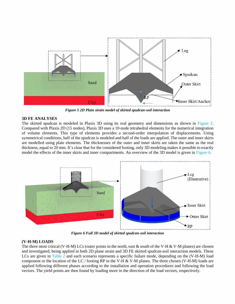
Figure 5 2D Plain strain model of skirted spudcan-soil interaction
3D FE ANALYSES
The skirted spudcan is modeled in Plaxis 3D using its real geometry and dimensions as shown in Figure 2.
Compared with Plaxis 2D (15 nodes), Plaxis 3D uses a 10-node tetrahedral elements for the numerical integration
of volume elements. This type of elements provides a second-order interpolation of displacements. Using
symmetrical conditions, half of the spudcan is modeled and half of the loads are applied. The outer and inner skirts
are modelled using plate elements. The thicknesses of the outer and inner skirts are taken the same as the real
thickness, equal to 20 mm. It’s clear that for the considered footing, only 3D modeling makes it possible to exactly
model the effects of the inner skirts and inner compartments. An overview of the 3D model is given in Figure 6.
Figure 6 Full 3D model of skirted spudcan-soil interaction
(V-H-M) LOADS
The three most critical (V-H-M) LCs (outer points in the north, east & south of the V-H & V-M planes) are chosen
and investigated, being applied in both 2D plane strain and 3D FE skirted spudcan-soil interaction models. These
LCs are given in Table 2 and each scenario represents a specific failure mode, depending on the (V-H-M) load
component or the location of the LC / footing RP in the V-H & V-M planes. The three chosen (V-H-M) loads are
applied following different phases according to the installation and operation procedures and following the load
vectors. The yield points are then found by loading more in the direction of the load vectors, respectively.

TABLE 2 CONSIDERED FOOTING REACTION (V-H-M) LOADS
Loads Description Vertical
(V)
Horizontal
(H)
Moment
(M)
Eccentricity
e = M/V
Units [tonnes/leg] [tonnes/leg] [tonnes*m/leg] [m]
Preload Reaction 3200 - - -
Still Water Reaction (SWR) 2325 - - -
Load Case 1 (LC1) 4020 300 3267 0.81
Load Case 2 (LC2) 2293 404 4647 2.03
Load Case 3 (LC3) 1447 457 2138 1.48
FOUNDATION CAPACITIES
For the considered preload of 3200 tonnes/leg, the predicted V-H and V-M bearing capacity envelopes, according
to SNAME [1] and considering the contact area for 2.5 m penetration, do not cover the most critical environmental
loads, as shown in Figure 17 in thin dashed line. Therefore, in order to satisfy SNAME [1] requirements regarding
structural utilizations, virtual bearing capacities can be adopted. These capacities are supposed to be larger than
the ones developed during preloading. In order to confirm these capacities, FE analyses, described above, are
undertaken, calculating the yield envelope by increasing the loads following the (V-H-M) load vector.
Alternatively, the yield envelope could be checked by keeping constant the V-H and increasing M or keeping
constant V-M and increasing H.
RESULTS – 2D AXISYMMETRIC FE ANALYSES
Plaxis 2D axisymmetric analyses are carried out to confirm the UVC for penetration 2.5 m, based on generalized
back-analyzed soil conditions / profile, as given in Table 1. A prescribed displacement is applied on top of the
spudcan to simulate the penetration of the footing. The mesh is refined at the skirt level and mesh sensitivity
analyses carried out coparing the results for different mesh coarseness. Plaxis output results are given in Figure 7
for the applied preload.
a) Total vertical displacement (uy)
b) Total deviatoric strain (γs) (Failure figure)
Figure 7 Plaxis 2D axisymmetric (plastic), UVC equal to 3200 tonnes/leg, spudcan in-placed at 2.5 m depth.
RESULTS – 2D PLANE STRAIN FE ANALYSES
Plaxis 2D plain strain analyses (small strain) are carried out first for vertical loading in order to confirm the UVC
for skirted spudcan in-placed at 2.5 m penetration. For achieving UVC=3200 tonnes/leg, the friction angle in 2D
plain strain is slightly increased (about 7%) from the one used in the axisymmetric model (25°), accounting for
the 3D and plane strain friction angles. The results from Plaxis (plastic) are given in Figure 8, where deformed
mesh, vertical displacements (uy), total deviatoric strain (γs) & cartesian effective stress (σ’yy), are shown.
Soil heave
Gap Local failure
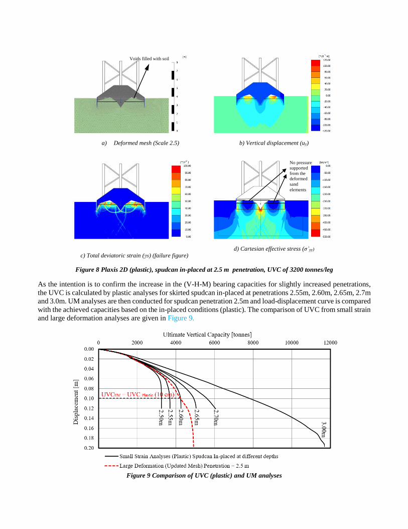
a) Deformed mesh (Scale 2.5) b) Vertical displacement (uy)
c) Total deviatoric strain (γs) (failure figure)
d) Cartesian effective stress (σ’yy)
Figure 8 Plaxis 2D (plastic), spudcan in-placed at 2.5 m penetration, UVC of 3200 tonnes/leg
As the intention is to confirm the increase in the (V-H-M) bearing capacities for slightly increased penetrations,
the UVC is calculated by plastic analyses for skirted spudcan in-placed at penetrations 2.55m, 2.60m, 2.65m, 2.7m
and 3.0m. UM analyses are then conducted for spudcan penetration 2.5m and load-displacement curve is compared
with the achieved capacities based on the in-placed conditions (plastic). The comparison of UVC from small strain
and large deformation analyses are given in Figure 9.
Figure 9 Comparison of UVC (plastic) and UM analyses
Voids filled with soil
No pressure
supported
from the
deformed
sand
elements
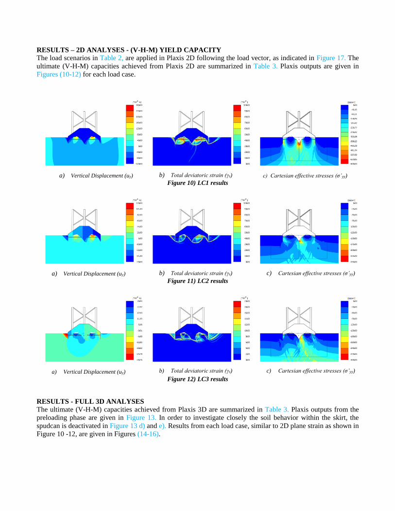
RESULTS – 2D ANALYSES - (V-H-M) YIELD CAPACITY
The load scenarios in Table 2, are applied in Plaxis 2D following the load vector, as indicated in Figure 17. The
ultimate (V-H-M) capacities achieved from Plaxis 2D are summarized in Table 3. Plaxis outputs are given in
Figures (10-12) for each load case.
a) Vertical Displacement (uy)
b) Total deviatoric strain (γs) c) Cartesian effective stresses (σ’yy)
Figure 10) LC1 results
a) Vertical Displacement (uy)
b) Total deviatoric strain (γs)
c) Cartesian effective stresses (σ’yy)
Figure 11) LC2 results
a) Vertical Displacement (uy)
b) Total deviatoric strain (γs)
c) Cartesian effective stresses (σ’yy)
Figure 12) LC3 results
RESULTS - FULL 3D ANALYSES
The ultimate (V-H-M) capacities achieved from Plaxis 3D are summarized in Table 3. Plaxis outputs from the
preloading phase are given in Figure 13. In order to investigate closely the soil behavior within the skirt, the
spudcan is deactivated in Figure 13 d) and e). Results from each load case, similar to 2D plane strain as shown in
Figure 10 -12, are given in Figures (14-16).

a) Vertical Displacement (uy)
b) Total deviatoric strain (γs)
c) Cartesian effective stresses (σ’zz)
d) Deformed mesh under the skirt
e) Total displacements (u)
f) Soil movement underside
Figure 13 3D results from preloading phase
a) Vertical Displacement (uy)
b) Total deviatoric strain (γs)
c) Cartesian effective stresses (σ’zz)
Figure 14 LC1 results
a) Vertical Displacement (uy)
b) Total deviatoric strain (γs)
c) Cartesian effective stresses (σ’zz)
Figure 15 LC2 results
a) Vertical Displacement (uy)
b) Total deviatoric strain (γs)
c) Cartesian effective stresses (σ’zz)
Figure 16 LC3 results
Soil heave Inner skirt compartments

RESULTS – ULTIMATE (V-H-M) YIELD CAPACITY
The (V-H-M) yield capacities derived from 2D and 3D FE analyses are summarized in Table 3. In addition, the
conventional yield capacities, considering the skirted spudcan as a block footing [10] with full base penetrations
at 2.5 m (gap filled with soil) are also included. In Figure 17 the achieved yield capacities are plotted in the
corresponding V-H and V-M envelopes. The numbers in the table represent how much more load can the model
hold until reaching the yield. So despite of limited penetrations and limited preload capacity, the skirted spudcans
can support the most critical (V-H-M) LCs and as expected, the 3D FE analyses give larger safety for those load
vectors than 2D FE analyses.
TABLE 3 ULTIMATE (V-H-M) CAPACITIES
LC 2D
(V-H-M)
3D
(V-H-M)
Conv.
(V-H-M)
LC1 1.13 1.38 2.00
LC2 1.40 1.41 1.60
LC3 1.30 1.50 1.40
a) Ultimate V-H capacity b Ultimate V-M capacity
Figure 17 Results, ultimate V-H & V-M capacities,
2D FE plane strain, (10-15) cm additional penetrations, maximum 2.65 m penetration-still gap;
3D FE (10-15) cm additional penetration, maximum 2.65 m penetration-still gap;
Conventional, maxim,um 2.5 m penetration and assumming gap is filled with heaving sand)
NONLINEAR SOIL STIFFNESS
The vertical, horizontal, and rotational stiffness can be derived from Plaxis 2D and 3D FE analyses, based on the
load displacement curves (vertical, horizontal) given in Figures (19-21) (for 2D) and based on the footing rotation
for each LC, as shown in Figure 18 (for 2D).
a) LC1, Rotation angle =0.1°
b) LC2, Rotation angle=0.39°
c) LC3, Rotation angle=0.06°
Figure 18 Footing rotation angles for the considered LCs
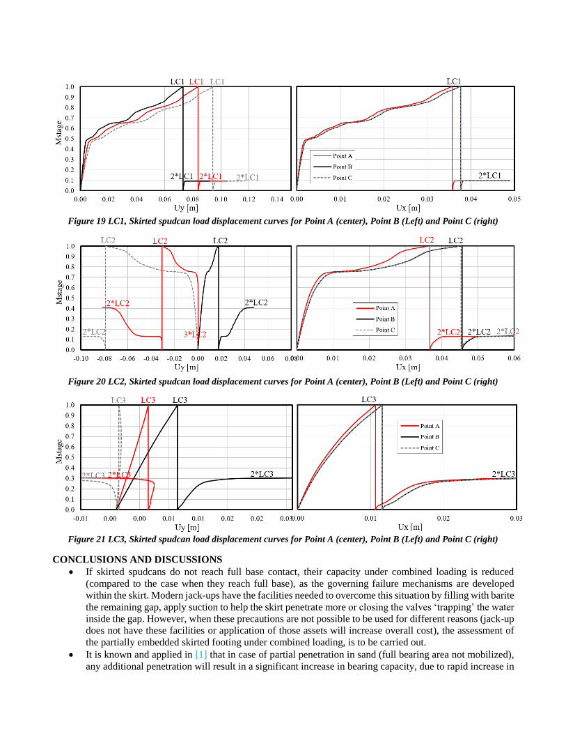
Figure 19 LC1, Skirted spudcan load displacement curves for Point A (center), Point B (Left) and Point C (right)
Figure 20 LC2, Skirted spudcan load displacement curves for Point A (center), Point B (Left) and Point C (right)
Figure 21 LC3, Skirted spudcan load displacement curves for Point A (center), Point B (Left) and Point C (right)
CONCLUSIONS AND DISCUSSIONS
If skirted spudcans do not reach full base contact, their capacity under combined loading is reduced
(compared to the case when they reach full base), as the governing failure mechanisms are developed
within the skirt. Modern jack-ups have the facilities needed to overcome this situation by filling with barite
the remaining gap, apply suction to help the skirt penetrate more or closing the valves ‘trapping’ the water
inside the gap. However, when these precautions are not possible to be used for different reasons (jack-up
does not have these facilities or application of those assets will increase overall cost), the assessment of
the partially embedded skirted footing under combined loading, is to be carried out.
It is known and applied in [1] that in case of partial penetration in sand (full bearing area not mobilized),
any additional penetration will result in a significant increase in bearing capacity, due to rapid increase in
the bearing area. To make use of this ‘benefit’, FE analysis is found as the best approach to model the
spudcan and the soil inside the skirt compartments. UM analyses is used to account for additional capacity
while the underside of the spudcan gets more contact with the soil.
The analyses performed include preloading of the spudcan and unloading to Still Water Reaction (SWR),
prior to the application of the most critical (V-H-M) LC.
Vertical Loading
The skirted spudcan (partially penetrated) under preloading conditions will develop a failure pattern as
given in Figure 7, Figure 8 and Figure 13.
While the spudcan penetrates further, a soil heave will develop within the skirt compartments, as seen
from 3D analyses in Figure 13 d) and e). The additional vertical capacity that comes due to additional
contact area is investigated by large deformation (UM) analyses (spudcan in-placed at 2.5 m of
penetration) and by small strain (plastic) analyses (spudcan in-placed at different depths until reaching full
base). The results given in Figure 9 show that for additional 10 cm penetration under vertical load, the
UM and plastic analyses give the same vertical capacity of about 4300 tonnes/leg. For larger penetrations,
UM analyses underestimate the vertical capacity. This is believed to come due to deformation of the mesh
elements under the spudcan and therefore limitation of the current modelling tool (Plaxis). Further
analyses are expected in the future by applying Abaqus or other FE programs.
Combined (V-H-M) Loading
The results of FE analyses indicate that due to application of (V-H-M) LCs, additional settlements and
rotation of the spudcan occur. The failure mechanism has been seen to be local and developed within the
skirt, in all three LCs. However, as LC1 has the largest V-component and the other two LCs have large H
and M, the failure mechanism changes from failure at skirt base with local failure around the skirt (LC1)
to sliding along base of the skirt and skirt tip (LC1, LC3).
The foundation bearing capacities indicate that the soil can hold the combined loads, with a minimum
safety for LC1 (1.13 2D; 1.34 3D) and larger safety for LC2 and LC3. Considering the results of FE
analyses (2D & 3D), a FE (V-H-M) yield envelope has been derived and plotted in Figure 17. This
envelope represents the ultimate (V-H-M) yield capacity, derived by considering additional contact area
that is developed while the spudcan rotate and penetrate further. The vertical capacity for this additional
penetrations is limited to about 5000 tonnes/leg, which is the capacity derived from small strain (plastic)
analyses for skirted spudcan in-placed at 2.65 m (15 cm additional vertical penetration).
Some differences are seen in the results derived from the 2D and 3D analyses, especially for LC1 and
LC3, where Plaxis 3D has shown more capacity. One reason for this might be the low order FE element
type (10 nodes) used in 3D, and the 3D coarser mesh. In addition, more capacity in 3D might also come
due to accurate modelling of the inner skirts, simulated by anchors in 2D.
The conventional analyses, considering the skirted spudcan as a block embedded footing to penetration
2.5 m (equivalent to assuming the gap filled with heaving seabed sand), has shown much larger capacity
for LC1, and similar capacities for LC2 and LC3. As the method assumes a full base spudcan, the failure
mechanism doesn’t consider failure of the soil within the skirt, but a more general bearing failure, similar
to the one from shallow foundations on sand or thick sand over stiff clay.
The proposed method and the analyses presented in this paper are expected to be applicable for similar
situations, jack-ups with skirted spudcans suffering limited penetrations during preloading. The method
can help in calculating additional capacity for each of the skirted spudcan legs, (due to expected larger
vertical pressure (larger than the applied maximum preload) on the spudcans (generally for aft legs) in the
elevated conditions) from the increase of the contact area while the skirted spudcans penetrates deeper. In
such a case, if the capacities (V-H-M) capacities are confirmed with satisfactory safety levels, it might be
no need for applying barite injection of suction during preloading.
For the current jack-up rig, the calculated 3D skirted spudcan yield capacities (for gap conditions), and
the large conventional capacities (for the assumed filled gaps due to heave of seabed sand, which was

considered possible), were found sufficient for installing the rig, which confirmed skirted spudcan
penetrations less than full base contact, similar to the predicted ones.
REFERENCES
[1] SNAME, Society of Naval Architects and Marine Engineers, Site Specific Assesment of mobile jack-up units.
SNAME Technical and Research Bulletin 5-5A, August 2008.
[2] EN ISO 19905-1, Petrolum and Natural Gas Industries - Site Specific Assessment of Mobile Offshore Units - Part 1,
Jack-ups, 2016.
[3] DNV, DNV, Foundations, Classification Notes No.30.4, 1992.
[4] HSE (Health and Safety Executive), Guidelines for Jack-up Rigs with Particular Reference to Foundation Integrity,
Research Report 289, 2004.
[5] L. Kellezi, H. Hofstede and P. Hansen, “Jack-up Footing Penetration and Fixity Analyses,” in Frontiers in Offshore
Geotechnics, ISFOG 2005, Perth, Australia, 2005.
[6] L. Kellezi, H. Denver, G. Kudsk and H. Stadsgaard, “FE Skirted Footings Analyses for Combined Loads and Layered
Soil Profile,” in 14th European Conference on Soil Mechanic and Geotechnical Engineering, ECSMGE, Madrid,
Spain, 2007.
[7] L. Kellezi, G. Kudsk and H. Hofstede, “Skirted Footings Capacity for Combined Loads and Layered Soil Conditions,”
in 2nd International Conference on Foundations, ICOF, Dundee, Scotland, 2008.
[8] Plaxis 2D, “Delft University of Technology, Finite Element Code for Soil and Rock Analysis, Plaxis BV,” Delft, The
Netherlands, 2017.
[9] Plaxis 3D, “Delft University of Technology, Finite Element Code for Soil and Rock Analysis, Plaxis BV,” Delft, The
Netherlands, 2013.
[10] J. Hansen, “A revised and extended formula for bearing capacity, The Danish Geotechnical Institute,” vol. Bulletin
No. 28, 1970.
[11] CEN/TC 250, EN-1997-1, Eurocode 7, Geotechnical Design - Part 1, General Rules, 2004.
[12] Plaxis 3D Foundation, “Delft University of Technology, Finite Element Code for Soil and Rock Analysis, Plaxis BV,”
2009.