Embed Size (px)
Citation preview
Skills for Employment
Investment Program (SEIP)
COMPETENCY-BASED LEARNING
MATERIAL
(STUDENT GUIDE)
FOR
CNC MACHINE OPERATION
(LIGHT ENGINEERING SECTOR)
Finance Division, Ministry of Finance
Government of the People’s Republic of Bangladesh

CBLM – CNC Machine Operation (Student Guide) v.1 Dec 2018 2
Skills for Employment Investment Programme (SEIP)
Table of Contents
Copyright 3
How to Use this Competency-based Learning Material 4
List of Icons 5
Modules 6
Module 1: Perform Basic Lathe Machine Operations 6
Learning Outcome 1.1 - Identify and prepare work requirements 7
Learning Outcome 1.2 - Prepare for lathe operations 13
Learning Outcome 1.3 - Perform basic lathe machine operations 21
Answer Keys 28
Module 2: Perform Basic Milling Operations 30
Learning Outcome 2.1 - Identify and prepare work requirements 31
Learning Outcome 2.2 - Prepare for milling operations 40
Learning Outcome 2.3 - Perform basic milling machine operations 52
Answer Keys 58
Module 3: Carry out CNC Lathe Machine Operations 60
Learning Outcome 3.1 - Set-up CNC lathe machine, workpiece and cutting tools 61
Learning Outcome 3.2 - Cut model/sample workpiece 66
Learning Outcome 3.3 - Perform CNC lathe machine operations 69
Learning Outcome 3.4 - Maintain CNC lathe machine, tools and equipment 72
Answer Keys 77
Module 4: Carry out CNC Milling Machine Operations 79
Learning Outcome 4.1 - Set-up CNC milling machine, workpiece and cutting tools 80
Learning Outcome 4.2 - Cut model/sample workpiece 85
Learning Outcome 4.3 - Perform CNC milling machine operations 89
Learning Outcome 4.4 - Maintain CNC milling machine, tools and equipment 93
Answer Keys 98
Module 5: Carry out CNC Wire Cut Machine Operations 100
Learning Outcome 5.1 - Prepare for CNC wire cut machine operations 101
Learning Outcome 5.2 - Set-up machine, wire and work piece 105
Learning Outcome 5.3 - Perform CNC wire cut operations in auto mode 109
Answer Keys 114
Module 6: Apply knowledge of CAM 115
Learning Outcome 6.1 - Prepare for CAM program, edit CNC program, load program and run
program at CNC machine 116

CBLM – CNC Machine Operation (Student Guide) v.1 Dec 2018 3
Skills for Employment Investment Programme (SEIP)
Copyright
The Competency-based Learning Material (Student Guide) for CNC Machine Operation is a document,
aligned to its applicable competency standard, for providing training consistent with the requirements of
industry in order for individuals who graduated through the established standard via competency-based
assessment to be suitably qualified for a relevant job.
This document is owned by the Finance Division of the Ministry of Finance of the People’s Republic of
Bangladesh, developed under the Skills for Employment Investment Program (SEIP).
Public and private institutions may use the information contained in this competency-based learning
material for activities benefitting Bangladesh.
Other interested parties must obtain permission from the owner of this document for reproduction of
information in any manner, in whole or in part, of this Competency-based Learning Material, in English or
other language.
This document is available from:
Skills for Employment Investment Program (SEIP) Project
Finance Division
Ministry of Finance
Probashi Kallyan Bhaban (Level – 16)
71-72 Old Elephant Road
Eskaton Garden, Dhaka 1000
Telephone: +8802 551 38598-9 (PABX), +8802 551 38753-5
Facsimile: +8802 551 38752
Website: www.seip-fd.gov.bd

CBLM – CNC Machine Operation (Student Guide) v.1 Dec 2018 4
Skills for Employment Investment Programme (SEIP)
How to Use this Competency-based Learning Material
Welcome to the competency-based learning material for CNC Machine Operation for use in light
engineering works. These modules contain training materials and activities for learners to complete in
order to become competent and qualified as a skilled worker.
There are six (6) modules that make up this course which comprises the skills, knowledge and attitudes
required to become a skilled worker including:
1. Perform basic lathe machine operations
2. Perform basic milling operations
3. Carry out CNC lathe machine operations
4. Carry out CNC milling machine operations
5. Carry out CNC wire cut machine operations
6. Apply knowledge of CAM
As a trainer, you are required to guide the learners through a series of activities in order to complete
each learning outcome of the module. These activities may be completed as part of structured classroom
activities or they may be required to work at their own pace.
These activities will require the learners to complete associated learning and practice activities in order to
gain knowledge and skills they need to achieve the learning outcomes. Refer to Learning Activity Page
of each module to know the sequence of learning tasks and the appropriate resources to use for each
task.
This page will serve as the road map towards the achievement of competence. If you read the
Information Sheets, these will give you an understanding of the work, and why things are done the way
they are. Once the learners have finished reading the Information Sheets, they are required to complete
the questions in the Self-Check Sheets.
The self-check process follows the Information Sheets in the learning guide. Completing self-checks will
help the learners know how they are progressing. To know how they fared with self-checks, they can
review the Answer Key.
The learners are required to complete all activities as directed in the Job Sheet. This is where they will
apply their newly acquired knowledge while developing new skills. When working, high emphasis should
be laid on safety requirements. The learners should be encouraged to raise relevant queries or ask the
facilitator for assistance as required.
When the learners have completed all the tasks required in the learning guide, an assessment event will
be scheduled to evaluate if they have achieved competency of the specified learning outcomes and are
ready for the next task.

List of Icons
Icon Name Icon
Module content
Learning outcomes
Performance criteria
Contents
Assessment criteria
Resources required
Information sheet
Self-check Quiz
Answer key
Activity
Video reference
Learner job sheet
Assessment plan
Review of competency

Module 1: Perform basic lathe machine operations
MODULE CONTENT
Module Descriptor: This module covers the knowledge, skills and attitudes required to
perform basic lathe machine operations. It specifically includes
identifying and preparing work requirements, preparing for lathe
operation and performing simple lathe operations such as facing, straight
and contour turning, cutting grooves, drilling, boring, and thread cutting.
Nominal Duration: 20 hours
LEARNING OUTCOMES:
Upon completion of the module, the student/trainee should be able to:
1.1. Identify and prepare work requirements
1.2. Prepare for lathe operations
1.3. Perform basic lathe machine operations
PERFORMANCE CRITERIA:
1. Drawings are interpreted to grind tools confirming to the specifications.
2. Tool holding devices are selected according to the requirements of the operation.
3. Cutting tools are selected according to requirements of the lathe operation.
4. Appropriate types of lathe machine are selected for different lathe operations.
5. Lathe accessories are used in accordance with the requirements of the operations.
6. Cutting speed, feed and depth of cut are selected in accordance with the job specifications.
7. Job materials are selected and collected in accordance with the job specifications.
8. Cutting tools are selected in accordance with the requirements of the operation.
9. Sequence of operation is determined to produce products to the specifications.
10. RPM, cutting speed, feed and depth of cut are calculated in accordance with the job requirement.
11. Machine performance is checked in conformance with the job requirement.
12. Coolant is applied to prevent over heating of work piece and cutting tool.
13. Basic lathe operations are performed to produce component.
14. Corrective measures/adjustments are performed if necessary.
15. Workpiece is checked and measured in conformance to specification using appropriate methods, measuring tools and equipment.

CBLM – CNC Machine Operation (Student Guide) v.1 Dec 2018 7
Skills for Employment Investment Programme (SEIP)
Learning Outcome 1.1 - Identify and Prepare Work Requirements
Contents:
▪ Interpret drawings to grind tools confirming to the specifications
▪ Select tool holding devices according to the requirements of the operation
▪ Select cutting tools according to requirements of the lathe operation
Assessment criteria:
▪ Drawings are interpreted to grind tools confirming to the specifications.
▪ Tool holding devices are selected according to the requirements of the operation.
▪ Cutting tools are selected according to requirements of the lathe operation.
Resources required:
Students/trainees must be provided with the following resources:
▪ Workplace (simulated or actual)
▪ Relevant drawings, manuals, codes, standards and reference material
▪ Tools holding devices and cutting tools appropriate to processes or activities
▪ Stationery
▪ Instruction sheet/manual
▪ Personal protective equipment (PPE)
LEARNING ACTIVITY 1.1.1
Learning Activity Resources/Special Instructions/References
Interpret drawings to grind tools confirming to the specifications
▪ Information Sheet: 1.1.1
▪ Self-Check Quiz: 1.1.1
▪ Answer Key: 1.1.1
INFORMATION SHEET 1.1.1
Learning Objective: to interpret drawings to grind tools confirming to the specifications.

CBLM – CNC Machine Operation (Student Guide) v.1 Dec 2018 8
Skills for Employment Investment Programme (SEIP)
▪ Bench grinding machine:
A bench grinder is a type of bench top grinding machine used to drive abrasive wheels. A pedestal grinder is a larger version of a bench grinder that is mounted on a pedestal, which is bolted to the floor. These types of grinders are commonly used to hand grind cutting tools and perform other rough grinding.
Depending on the grade of the grinding wheel it may be used for sharpening cutting tools such as lathe tools or drill bits. Alternatively, it may be used to roughly shape metal prior to welding or fitting. A wire brush wheel or buffing wheels can be interchanged with the grinding wheels in order to clean or polish work-pieces. Grinding wheels designed for steel should not be used for grinding softer metals, like aluminium. The soft metal gets lodged in the pores of the wheel and expands with the heat of grinding. This can dislodge pieces of the grinding wheel.
▪ Single point cutting tools:
The tool is wedge shape object of hard material. It is usually made from H.S.S. Beside H.S.S. machine tool is also made from high carbon steel, satellite, ceramics, diamond, abrasive, etc. The main requirement of tool material is hardness. It must be hard enough to resist cutting forces applied on work piece.
▪ Single point cutting tool geometry
The single point cutting tool mainly consist of tool
shank and cutting part called point. The point of
cutting tool is bounded by cutting face, end flank,
side/main flank, and base. The chip slides along
the face. The side/main cutting edge ‘ab’ is formed
by intersecting of face and side/main flank. The
end cutting edge ‘ac’ is formed by the intersection
of end flank and base. The point ‘a’ which the
intersection of end cutting edge and side cutting
edge is called nose. Mainly the chip cuts by side
cutting edge.
▪ Single point cutting tool grinding angle and different lathe operation tool grinding shapes:
▪ Bench and Pedestal grinders safety precaution:
Grinding machines are used daily in a machine shop. To avoid injuries, follow the safety precautions listed below.
➢ Fasten pedestal and bench grinders securely.
➢ Ensure all the guards are in place and secure before using a grinder.
➢ Adjust tool rests to within 3 mm (1/8 in.) of wheels. Never adjust rests while wheels are moving. Work rest height should be on horizontal centre line of the machine spindle.
➢ Maintain 6 mm (1/4 in.) wheel exposure with a tongue guard or a movable guard.
➢ Check that wheels have blotters on each side.

CBLM – CNC Machine Operation (Student Guide) v.1 Dec 2018 9
Skills for Employment Investment Programme (SEIP)
➢ Check the wheel fits properly to the spindle when mounting. If it is loose, get another wheel.
➢ Stand to one side of the grinder until the wheel reaches operating speed.
➢ Bring work into contact with the grinding wheel slowly and smoothly, without bumping.
➢ Apply gradual pressure to allow the wheel to warm up evenly. Use only the pressure required to complete a job.
➢ Move the work back and forth across the face of the wheel. This movement prevents grooves from forming.
➢ Wheels are made only for grinding certain items. Do not grind rough forgings on a small precision grinding wheel.
➢ Dress wheels regularly. Do frequent, light dressings rather than one heavy dressings.
➢ Support dressing tools so you can apply leverage without undue effort. With revolving cutter dressing tools use the lugs as anchors.
➢ Replace worn wheels if you cannot dress it.
➢ Ensure the grinder speed does not exceed the operating speed marked on the wheel.
➢ Visually inspect wheels for possible damage before mounting.
➢ Wear proper personal protective equipment: eye, ear and face protection, metatarsal safety boots, where required, respiratory protection may be required, depending on the work.
➢ Wear gloves only where necessary.
▪ What should you avoid when using bench and pedestal grinders?
➢ Do not use a wheel that has been dropped.
➢ Do not use a wheel that does not fit properly to the spindle.
➢ Do not use excessive force to tighten the nut of the wheel. The force can crack the wheel.
➢ Do not grind wood, plastics and non-iron metals on ordinary wheels.
➢ Do not leave grinding wheels standing in liquids. The liquid can cause balance problems.
➢ Do not grind on the side of a regular wheel.
SELF-CHECK QUIZ 1.1.1
Write true or false for the following statements:
1. Single point cutting tool is the simplest form of cutting tool and it have only one cutting edge.
2. The surface or surface below the adjacent of the cutting edge is called shank of the tool.
3. Ensure all the guards are in place and secure before using a grinder.
4. Bring work into contact with the grinding wheel rapidly and smoothly, without bumping.
5. Wear proper personal protective equipment for tool grinding:
• eye, ear and face protection,
• metatarsal safety boots, where required,
• respiratory protection may be required, depending on the work

CBLM – CNC Machine Operation (Student Guide) v.1 Dec 2018 10
Skills for Employment Investment Programme (SEIP)
LEARNING ACTIVITY 1.1.2
Learning Activity Resources/Special Instructions/References
Select tool holding devices according to the requirements of the operation
▪ Information Sheet: 1.1.2
▪ Self-Check Quiz: 1.1.2
▪ Answer Key: 1.1.2
INFORMATION SHEET 1.1.2
Learning Objective: to select tool holding devices according to the requirements of the operation.
▪ Lathe Tool Post
Versatile lathe tool posts and lathe tool post holders allow you to easily swap out tooling from one operation to the other. They help reduce down time and the need for shims and additional accessories to achieve the set up required for each operation. They also provide the positive control and repetitive accuracy needed for your boring, grooving, and knurling operations. Grainger offers a wide selection of tool sets and accessories that are ideal for most machining applications.
▪ Lathe Tool holders
Lathe tool holders securely hold carbide inserts for a variety of lathe operations such as turning, boring, facing, grooving, threading, and parting etc. There are several mechanisms by which indexable carbide inserts can be mounted to a lathe tool holder.
CBLM – CNC Machine Operation (Student Guide) v.1 Dec 2018 11
Skills for Employment Investment Programme (SEIP)
SELF-CHECK QUIZ 1.1.2
Write true or false for the following statements:
1. The tool post is assembled to the swivel base.
2. The tool is positioned on rocket arm and clamped in case of single way tool post.
3. Open slide tool post is clamped in position by 2 set screws.
4. The indexing is automatic in four-way tool post.
5. Frequent changing of the tool for different operations need not be done in four-way tool post.
LEARNING ACTIVITY 1.1.3
Learning Activity Resources/Special Instructions/References
Select cutting tools according to requirements of the lathe operation
▪ Information Sheet: 1.1.3
▪ Self-Check Quiz: 1.1.3
▪ Answer Key: 1.1.3
INFORMATION SHEET 1.1.3
Learning Objective: to select cutting tools according to requirements of the lathe operation.
▪ Lathe operation
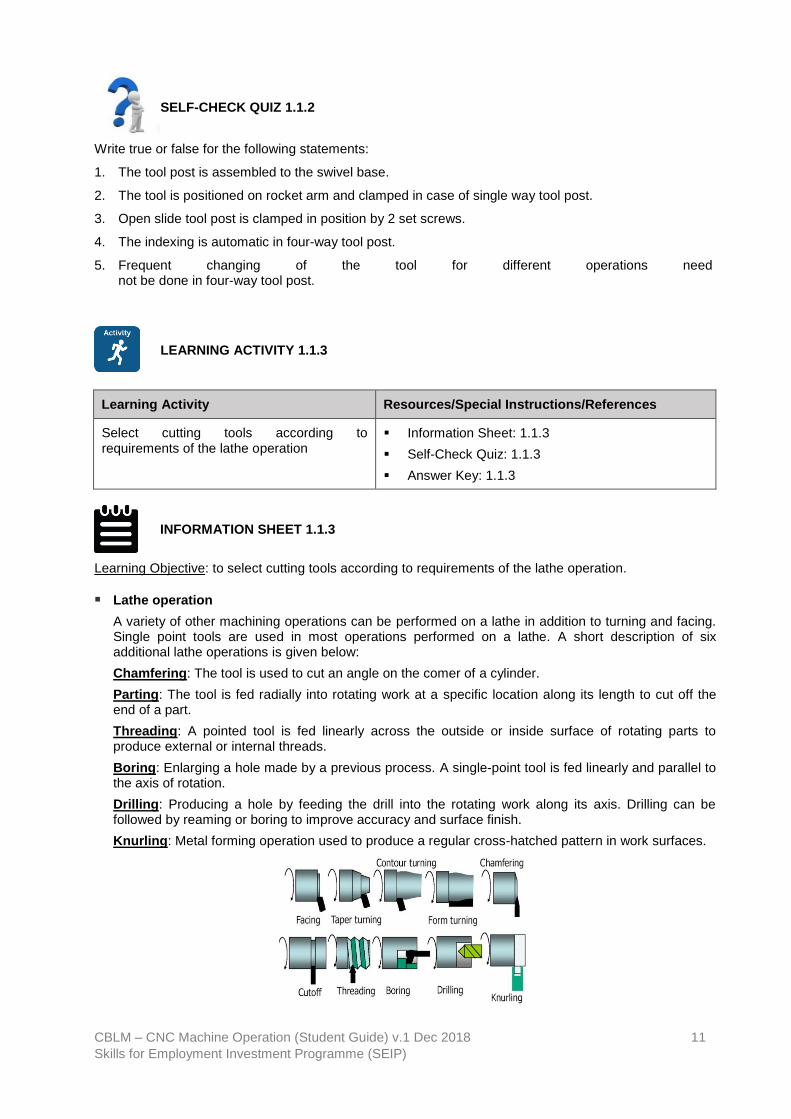
A variety of other machining operations can be performed on a lathe in addition to turning and facing. Single point tools are used in most operations performed on a lathe. A short description of six additional lathe operations is given below:
Chamfering: The tool is used to cut an angle on the comer of a cylinder.
Parting: The tool is fed radially into rotating work at a specific location along its length to cut off the end of a part.
Threading: A pointed tool is fed linearly across the outside or inside surface of rotating parts to produce external or internal threads.
Boring: Enlarging a hole made by a previous process. A single-point tool is fed linearly and parallel to the axis of rotation.
Drilling: Producing a hole by feeding the drill into the rotating work along its axis. Drilling can be followed by reaming or boring to improve accuracy and surface finish.
Knurling: Metal forming operation used to produce a regular cross-hatched pattern in work surfaces.

CBLM – CNC Machine Operation (Student Guide) v.1 Dec 2018 12
Skills for Employment Investment Programme (SEIP)
SELF-CHECK QUIZ 1.1.3
Write true or false for the following statements:
1. For lathe operations, work piece can be hold between centres.
2. Drilling is performed by holding the work by a chuck.
3. Knurling can be performed by special attachments.
4. Eccentric turning can be performed by using special attachments.
5. The threading tool is clamped in the tool post on the compound slide.

CBLM – CNC Machine Operation (Student Guide) v.1 Dec 2018 13
Skills for Employment Investment Programme (SEIP)
Learning Outcome 1.2 - Prepare for Lathe Operations
Contents:
▪ Select appropriate types of lathe machine for different lathe operations
▪ Use lathe accessories in accordance with the requirements of the operations
▪ Select cutting speed, feed and depth of cut in accordance with the job specifications
Assessment criteria:
▪ Appropriate types of lathe machine are selected for different lathe operations.
▪ Lathe accessories are used in accordance with the requirements of the operations.
▪ Cutting speed, feed and depth of cut are selected in accordance with the job specifications.
Resources required:
Students/trainees must be provided with the following resources:
▪ Workplace (simulated or actual)
▪ Relevant drawings, manuals, codes, standards and reference material
▪ Lathe machine and accessories, cutting tools appropriate to processes or activities
▪ Stationery
▪ Instruction sheet/manual
▪ Personal protective equipment (PPE)
LEARNING ACTIVITY 1.2.1
Learning Activity Resources/Special Instructions/References
Select appropriate types of lathe machine for different lathe operations
▪ Information Sheet: 1.2.1
▪ Self-Check Quiz: 1.2.1
▪ Answer Key1.2.1
INFORMATION SHEET 1.2.1
Learning Objective: to select appropriate types of lathe machine for different lathe operations.

CBLM – CNC Machine Operation (Student Guide) v.1 Dec 2018 14
Skills for Employment Investment Programme (SEIP)
▪ Types of Lathe machine:
Lathes can be divided into three types for easy identification: engine lathes, turret lathes, and special purpose lathes. Small lathes can be bench mounted, are lightweight, and can be transported in wheeled vehicles easily. The larger lathes are floor mounted and may require special transportation if they must be moved. Field and maintenance shops generally use a lathe that can be adapted to many operations and that is not too large to be moved from one work site to another. The engine lathe is ideally suited for this purpose. A trained operator can accomplish more machining jobs with the engine lathe than with any other machine tool. Turret lathes and special purpose lathes are usually used in production or job shops for mass production or specialized parts. While basic engine lathes are usually used for any type of lathe work.
Engine Lathes: These are probably the most popular among the lathe machines. In fact, no machine shop is seen without this type of lathe. The good thing about engine lathes is that it can be used in various materials, aside from metal. Moreover, the set-up of these machines is so simple that they are easier to use. Its main components include the bed, headstock, and tailstock. These engine lathes can be adjusted to variable speeds for the accommodation of a wide scope of work. In addition, these lathes come in various sizes.
Turret Lathes: These types of lathes are used for machining single work pieces sequentially. This means that several operations are needed to be performed on a single work piece. With the turret lathes, sequential operations can be done on the work piece, eliminating errors in work alignment. With this set-up, machining is done more efficiently. Correspondingly, time is saved because there is no need to remove and transfer the work piece to another machine anymore.
Special Purpose Lathes: As the name implies, these lathes are used for special purposes such as heavy-duty production of identical parts. In addition, these lathes also perform specific functions that cannot be performed by the standard lathes. Some examples of special purpose lathes include the bench-type jewellers’ lathes, automatic lathes, crankshaft lathes, duplicating lathes, multi-spindle lathes, brake drum lathes, and production lathes among others.
CNC Lathe Machine: A CNC Lathe Machine is abbreviated as Computer Numerical Control Lathe Machine. It is generally operated by precisely programmed commands encoded on a storage medium. A CNC Machine uses computer controls to cut different materials. CNC Computer Numerical Control machines are widely used in manufacturing industry. The CNC machine comprises of the computer in which the program
CBLM – CNC Machine Operation (Student Guide) v.1 Dec 2018 15
Skills for Employment Investment Programme (SEIP)
is fed for cutting of the metal of the job as per the requirements. The main function of CNC machines is to remove some of the metal so as to give it proper shape such as round, rectangular, etc. A CNC system consists of three basic components (i) Part program and (ii) Machine Control Unit (MCU).
SELF-CHECK QUIZ 1.2.1
Write true or false for the following statements:
1. Engine lathe is also known as centre lathe.
2. Lathe centres are made up of very hard materials.
3. The shanks of all the centres are machined to the metric 2 to 4 standard taper.
4. Geared lathe is the type of engine lathe.
5. Wood working lathe is the example of capstan and turret lathe.
LEARNING ACTIVITIES 1.2.2
Learning Activity Resources/Special Instructions/References
Use lathe accessories in accordance with the requirements of the operations
▪ Information Sheet: 1.2.2
▪ Self-Check Quiz: 1.2.2
▪ Answer Key: 1.2.2
INFORMATION SHEET 1.2.2
Learning Objective: to use lathe accessories in accordance with the requirements of the operations.
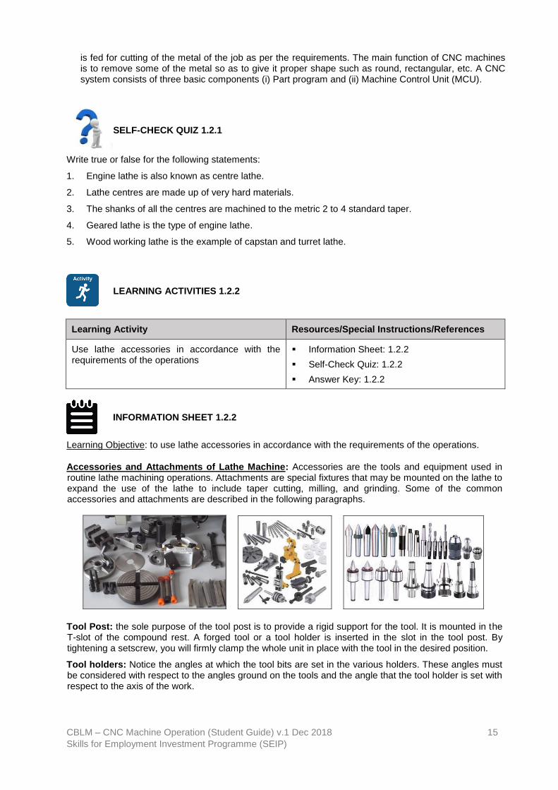
Accessories and Attachments of Lathe Machine: Accessories are the tools and equipment used in routine lathe machining operations. Attachments are special fixtures that may be mounted on the lathe to expand the use of the lathe to include taper cutting, milling, and grinding. Some of the common accessories and attachments are described in the following paragraphs.
Tool Post: the sole purpose of the tool post is to provide a rigid support for the tool. It is mounted in the T-slot of the compound rest. A forged tool or a tool holder is inserted in the slot in the tool post. By tightening a setscrew, you will firmly clamp the whole unit in place with the tool in the desired position.
Tool holders: Notice the angles at which the tool bits are set in the various holders. These angles must be considered with respect to the angles ground on the tools and the angle that the tool holder is set with respect to the axis of the work.

CBLM – CNC Machine Operation (Student Guide) v.1 Dec 2018 16
Skills for Employment Investment Programme (SEIP)
Lathe chuck: Lathe chuck is a device for holding lathe work. It is mounted on the nose of the spindle. The work is held by jaws which can be moved in radial slots toward the centre of the chuck to clamp down on the sides of the work. These jaws are moved in and out by screws turned by a special chuck wrench.
The four-jaw independent lathe chuck is the most practical chuck for general work. The four jaws are adjusted one at a time, making it possible to hold work of various shapes and to adjust the centre of the work to coincide with the axis of the spindle. The jaws are reversible.
The three-jaw universal or scroll chuck can be used only for holding round or hexagonal work all three jaws move in and out together in one operation and bring the work on centre automatically. This chuck is easier to operate than the four-jaw type, but, when its parts become worn, its accuracy in centring cannot be relied upon. Proper lubrication and constant care are necessary to ensure reliability.
The draw-in collet chuck is used to hold small work for machining in the lathe. It is the most accurate type of chuck made and is intended for precision work. The collet, which holds the work, is a split-cylinder with an outside taper that fits into the tapered closing sleeve and screws into the threaded end of the hollow drawbar. As the hand wheel is turned clockwise, the drawbar is moved toward the hand wheel. This tightening up on the drawbar pulls the collet back into the tapered sleeve, thereby closing it firmly over the work and centring the work accurately and quickly. The size of the hole in the collet determines the diameter of the work the chuck can handle.
Faceplates the faceplate is used for holding work that, because of its shape and dimensions, cannot be swung between centres or in a chuck. The T-slots and other openings on its surface provide convenient anchors for bolts and clamps used in securing the work to it. The faceplate is mounted on the nose of the spindle.
The driving plate is similar to a small faceplate and is used mainly for driving work that is held between centres. The primary difference between a faceplate and a driving plate is that a faceplate has a machined face for precision mounting, while the face of a driving plate is left rough. When a driving plate is used, the bent tail of a dog clamped to the work is inserted into a slot in the faceplate. This transmits rotary motion to the work.
Lathe Centres: The 60-degree lathe centres provide a way to hold the work so it can be turned accurately on its axis. The headstock spindle centre is called the live centre because it revolves with the work. The tailstock centre is called the dead centre because it does not turn. Live and dead centres have shanks turned to a Morse taper to fit the tapered holes in the spindles; both have points finished to an angle of 60°. They differ only in that the dead centre is hardened and tempered to resist the wearing effect of the work revolving on it. The live centre revolves with the work and is usually left soft. The dead centre and live centre must never be interchanged. (There is a groove around the hardened dead centre to distinguish it from the live centre.)
Lathe Dogs: Lathe dogs are used with a driving plate or faceplate to drive works being machined on centres; the frictional contact alone between the live centre and the work is not enough to drive the work. The common lathe dog is used for round work or work having a regular section (square, hexagon, and octagon). The piece to be turned is held firmly in the hole (A) by the setscrew (B). The bent tail (C) projects through a slot or hole in the driving plate or faceplate so that when the tail revolves with the spindle it turns the work with it. The clamp dog may be used for rectangular or irregularly shaped work. Such work is clamped between the jaws,

CBLM – CNC Machine Operation (Student Guide) v.1 Dec 2018 17
Skills for Employment Investment Programme (SEIP)
Centre Rest: The centre rest, also called the steady rest, is used for the following purposes:
➢ To provide an intermediate support for long slender bars or shafts being machined between centres. The centre rest prevents them from springing, or sagging, as a result of their otherwise unsupported weight.
➢ To support and provide a centre bearing for one end of the work, such as a shaft, being bored or drilled from the end when it is too long to be supported by a chuck alone. The centre rest is clamped in the desired position on the bed and is kept aligned by the ways. The jaws (A) must be carefully adjusted to allow the work (B) to turn freely and at the same time remain accurately centred on the axis of the lathe. The top half of the frame is a hinged section (C) for easier positioning without having to remove the work from the centres or to change the position of the jaws.
Follower Rest: The follower rest is used to back up small diameter work to keep it from springing under the cutting pressure. It can be set to either precede or follow the cutting action. It is attached directly to the saddle by bolts (B). The adjustable jaws bear directly on the part of the work opposite the cutting tool.
Taper Attachment: The taper attachment is used for turning and boring tapers. It is bolted to the back of the carriage. In operation, it is connected to the cross slide so that it moves the cross-slide traversal as the carriage moves longitudinally, thereby causing the cutting tool to move at an angle to the axis of the work to produce a taper.
The desired angle of taper is set on the guide bar of the attachment. The guide bar support is clamped to the lathe bed Since the cross slide is connected to a shoe that slides on this guide bar, the tool follows along a line parallel to the guide bar and at an angle to the work axis corresponding to the desired taper. The operation of the taper attachment will be further explained under the subject of taper work.
Thread Dial Indicator: The thread dial indicator, the need to reverse the lathe to return the carriage to the starting point each time a successive threading cut is taken. The dial, which is geared to the lead screw, indicates when to clamp the half-nuts on the lead screw for the next cut. The threading dial consists of a worm wheel which is attached to the lower end of a shaft and meshed with the lead screw. On the upper end of the shaft is the dial. As the lead screw revolves, the dial is turned and the graduations on the dial indicate points at which the half-nuts may be engaged.
SELF-CHECK QUIZ 1.2.2
Write true or false for the following statements:
1. Carriers are also known as lathe dogs.
2. The shanks of all the centres are machined to the Morse 0 to 3 tapers.
3. The threading tool is clamped in the tool post on the compound slide.
4. Three jaw chuck is also known as universal or self-centre chuck.
5. Four jaw chucks are dependent chuck.

CBLM – CNC Machine Operation (Student Guide) v.1 Dec 2018 18
Skills for Employment Investment Programme (SEIP)
LEARNING ACTIVITY 1.2.3
Learning Activity Resources/Special Instructions/References
Select cutting speed, feed and depth of cut in accordance with the job specifications
▪ Information Sheet: 1.2.3
▪ Self-Check Quiz: 1.2.3
▪ Answer Key: 1.2.3
INFORMATION SHEET 1.2.3
Learning Objective: to select cutting speed, feed and depth of cut in accordance with the job specifications.
Cutting Speed for Turning: Cutting speed is the speed at the outside edge of the part as it is rotating. This is also known as surface speed. Surface speed, surface footage, and surface area are all directly related. Two wheels can illustrate this. Take two wheels, one wheel which is three feet in diameter and the other wheel which is one foot in diameter, roll each wheel one complete turn.
Lathe speeds, feed and depth of cuts: General operations on the lathe include straight and shoulder turning, facing, grooving, parting, turning tapers, and cutting various screw threads. Before these operations can be done, a thorough knowledge of the variable factors of lathe speeds, feeds, and depth of cut must be understood. These factors differ for each lathe operation, and failure to use these factors properly will result in machine failure or work damage. The kind of material being worked, the type of tool bit, the diameter and length of the work piece, the type of cut desired (roughing or finishing), and the working condition of the lathe will determine which speed, feed, or depth of cut is best for any particular operation. The guidelines which follow for selecting speed, feed, and depth of cut are general in nature and may need to be changed as conditions dictate.
Cutting Speeds: The cutting speed of a tool bit is defined as the number of feet/meters of work piece surface, measured at the circumference that passes the tool bit in one minute. The cutting speed, expressed in FPM / MPM, must not be confused with the spindle speed of the lathe which is expressed in RPM. To obtain uniform cutting speed, the lathe spindle must be revolved faster for workplaces of small diameter and slower for workplaces of large diameter. The proper cutting speed for a given job depends upon the hardness of the material being machined, the material of the tool bit, and how much feed and depth of cut is required. Cutting speeds for metal are usually expressed in surface feet per minute, measured on the circumference of the work. Spindle revolutions per minute (RPM) are determined by using the formula:
D
SFM4
D3.14
SFM12RPM
=
Where:
SFM is the rated surface feet per minute, also expressed as cutting speed.
RPM is the spindle speed in revolutions per minute.
D is the diameter of the work in inches.
To use the formula, simply insert the cutting speed of the metal and the diameter of the work piece into the formula and you will have the RPM.
Turning a one-half inch piece of aluminium cutting speed of 200 SFM would result in the following:
1600
2
1
2004RPM =
=
Table 1 consists of specific ranges of cutting speeds for turning and threading various materials under normal lathe conditions, using normal feeds and depth of cuts. Note that in Table 1 the measurement calculations are in inch and metric measures. The diameter measurements used in these calculations

CBLM – CNC Machine Operation (Student Guide) v.1 Dec 2018 19
Skills for Employment Investment Programme (SEIP)
are the actual working diameters that are being machined and not necessarily the largest diameter of the material. The cutting speeds have a wide range so that the lower end of the cutting speed range can be used for rough cutting and the higher end for finish cutting. If no cutting speed tables are available, remember that, generally hard materials require a slower cutting speed than soft or ductile materials. Materials that are machined dry without coolant require a slower cutting speed than operations using coolant. Lathes that are worn and in poor condition will require slower speeds than machines that is in good shape. If carbide-tipped tool bits are being used, speeds can be increased two to three times the speed used for high speed tool bits.
Table 1: Cutting speeds for straight turning and threading with HSS too bits.
Metric cutting speed:
Feed: Feed is the term applied to the distance the tool bit advances along the work for each revolution of
the lathe spindle. Feed is measured in inches or mm per revolution, depending on the lathe used and the
operator’s system of measurement. A light feed must be used on slender and small workplaces to avoid
damage. If an irregular finish or chatter marks develop while turning. Reduce the feed and check the tool
bit for alignment and sharpness. Regardless of how the work is held in the lathe, the tool should feed
toward the headstock. This results in most of the pressure of the cut being put on the work holding
device, If the cut must be fed toward the tailstock. Use light feeds and light cuts to avoid pulling the work
piece loose.
Depth of Cut: Depth of cut is the distance that the tool bit moves into the work. Usually measured in
thousandths of an inch or in mm. General machine practice is to use a depth of cut up to five times the
rate of feed, such as rough cutting stainless steel using a feed of 0.020 inch per revolution and a depth of
cut of 0.100 inch. This would reduce the diameter by 0.200 inch. If chatter marks or machine noise
develops, reduce the depth of cut.
SELF-CHECK QUIZ 1.2.3
Write true or false for the following statements:
1. Depth of cutis the speed at which the metal is removed by the tool from the work piece.
2. Feed is the distance the tool advances for each revolution of the work.

CBLM – CNC Machine Operation (Student Guide) v.1 Dec 2018 20
Skills for Employment Investment Programme (SEIP)
3. M/Min is the unit of the feed.
4. The depth of cut is the parallel distance measured from the machined surface to the surface of the work piece, which is uncut.
5. For general purposes, ratio of the depth of cut to the feed varies from10:1.

CBLM – CNC Machine Operation (Student Guide) v.1 Dec 2018 21
Skills for Employment Investment Programme (SEIP)
Learning Outcome 1.3 - Perform Basic Lathe Machine Operations
Contents:
▪ Perform basic lathe operations to produce component
▪ Perform corrective measures/adjustments if necessary
▪ Check and measure workpiece in conformance to specification using appropriate methods, measuring tools and equipment
Assessment criteria:
▪ Basic lathe operations are performed to produce component.
▪ Corrective measures/adjustments are performed.
▪ Workpiece is checked and measured in conformance to specification using appropriate methods, measuring tools and equipment.
Resources required:
Students/trainees must be provided with the following resources:
▪ Workplace (simulated or actual)
▪ Relevant drawings, manuals, codes, standards and reference material
▪ Lathe machine and accessories, cutting tools appropriate to processes or activities
▪ Stationery
▪ Instruction sheet/manual
▪ Personal protective equipment (PPE)
LEARNING ACTIVITY 1.3.1
Learning Activity Resources/Special Instructions/References
Perform basic lathe operations to produce component
▪ Information Sheet: 1.3.1
▪ Self-Check Quiz: 1.3.1
▪ Answer Key: 1.3.1

CBLM – CNC Machine Operation (Student Guide) v.1 Dec 2018 22
Skills for Employment Investment Programme (SEIP)
INFORMATION SHEET 1.3.1
Learning Objective: to perform basic lathe operations to produce component.
Facing: Facing is usually performed with the work held in a chuck or collet. Allow the work piece to extend a distance no more than 1 1/2 times the work diameter from the chuck jaws and use finishing speeds and feeds calculated using the largest diameter of the work piece. The tool bit may be fed from the outer edge to the centre or from the centre to the outer edge. Normal facing is done from the outer edge to the centre since this method permits the operator to observe the tool bit and layout line while starting the cut. This method also eliminates the problem of feeding the tool bit into the solid centre portion of the work piece to get a cut started.
Use a left-hand finishing tool bit and a right-hand tool holder when facing from the outer edge toward the centre. Work that has a drilled or bored hole in the centre may be faced from the centre out to the outer edge if a right-hand finishing tool bit is used. Avoid excessive tool holder and tool bit overhang when setting up the facing operation. Set the tool bit exactly on centre to avoid leaving a centre nub on the work piece. Use the tailstock centre point as a reference point when setting the tool bit exactly on centre. If no tailstock centre is available, take a trial cut and readjust as needed. If using the cross-slide power feed to move the tool bit (into the centre), disengage power when the tool bit is within l/16 inch of the centre and finish the facing cut using hand feed.
Straight Turning: Straight turning, sometimes called cylindrical turning, is the process of reducing the work diameter to a specific dimension as the carriage moves the tool along the work. The work is machined on a plane parallel to its axis so that there is no variation in the work diameter throughout the length of the cut. Straight turning usually consists of a roughing cut followed by a finishing cut. When a large amount of material is to be removed, several roughing cuts may need to be taken. The roughing cut should be as heavy as the machine and tool bit can withstand. The finishing cut should be light and made to cut to the specified dimension in just one pass of the tool bit. When using power feed to machine to a specific length, always disengage the feed approximately 1/16-inch away from the desired length dimension, and then finish the cut using hand feed.
Grooves: Grooving (or necking) is the process of turning a groove or furrow on a cylinder, shaft, or work piece. The shape of the tool and the depth to which it is fed into the work govern the shape and size of the groove. The types of grooves most commonly used are square, round, and V-shape. Square and round grooves are frequently cut on work to provide a space for tool run out during subsequent machining operations, such as threading or knurling. These grooves also provide a clearance for assembly of different parts. The V-shaped groove is used extensively on step pulleys made to fit a V-type belt. The grooving tool is a type of forming tool. It is ground without side or back rake angles and set to the work at center height with a minimum of overhang. The side and end relief angles are generally somewhat less than for turning tools.
CBLM – CNC Machine Operation (Student Guide) v.1 Dec 2018 23
Skills for Employment Investment Programme (SEIP)
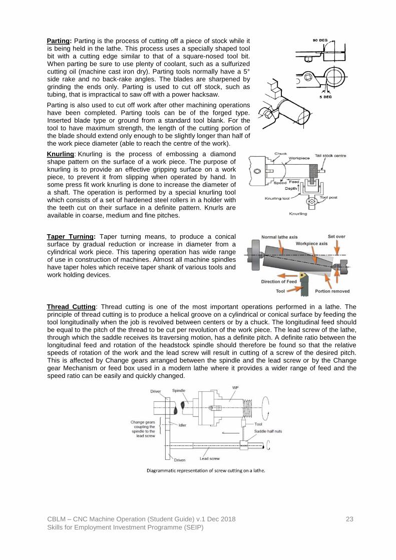
Parting: Parting is the process of cutting off a piece of stock while it is being held in the lathe. This process uses a specially shaped tool bit with a cutting edge similar to that of a square-nosed tool bit. When parting be sure to use plenty of coolant, such as a sulfurized cutting oil (machine cast iron dry). Parting tools normally have a 5° side rake and no back-rake angles. The blades are sharpened by grinding the ends only. Parting is used to cut off stock, such as tubing, that is impractical to saw off with a power hacksaw.
Parting is also used to cut off work after other machining operations have been completed. Parting tools can be of the forged type. Inserted blade type or ground from a standard tool blank. For the tool to have maximum strength, the length of the cutting portion of the blade should extend only enough to be slightly longer than half of the work piece diameter (able to reach the centre of the work).
Knurling: Knurling is the process of embossing a diamond shape pattern on the surface of a work piece. The purpose of knurling is to provide an effective gripping surface on a work piece, to prevent it from slipping when operated by hand. In some press fit work knurling is done to increase the diameter of a shaft. The operation is performed by a special knurling tool which consists of a set of hardened steel rollers in a holder with the teeth cut on their surface in a definite pattern. Knurls are available in coarse, medium and fine pitches.
Taper Turning: Taper turning means, to produce a conical surface by gradual reduction or increase in diameter from a cylindrical work piece. This tapering operation has wide range of use in construction of machines. Almost all machine spindles have taper holes which receive taper shank of various tools and work holding devices.
Thread Cutting: Thread cutting is one of the most important operations performed in a lathe. The principle of thread cutting is to produce a helical groove on a cylindrical or conical surface by feeding the tool longitudinally when the job is revolved between centers or by a chuck. The longitudinal feed should be equal to the pitch of the thread to be cut per revolution of the work piece. The lead screw of the lathe, through which the saddle receives its traversing motion, has a definite pitch. A definite ratio between the longitudinal feed and rotation of the headstock spindle should therefore be found so that the relative speeds of rotation of the work and the lead screw will result in cutting of a screw of the desired pitch. This is affected by Change gears arranged between the spindle and the lead screw or by the Change gear Mechanism or feed box used in a modern lathe where it provides a wider range of feed and the speed ratio can be easily and quickly changed.

CBLM – CNC Machine Operation (Student Guide) v.1 Dec 2018 24
Skills for Employment Investment Programme (SEIP)
SELF-CHECK QUIZ 1.3.1
Write true or false for the following statements:
1. Facing is usually performed with the work held in a drive plate.
2. Straight turning, sometimes called cylindrical turning, is the process of reducing the work diameter to
a specific dimension as the carriage moves the tool along the work.
3. The purpose of knurling is to provide an effective gripping surface on a work piece, to prevent it from
slipping when operated by hand.
4. Attachment method can produce only small taper.
5. The form tool should be set parallel to the axis of the work.
LEARNING ACTIVITY 1.3.2
Learning Activity Resources/Special Instructions/References
Check and measure workpiece in conformance to specification using appropriate methods, measuring tools and equipment
▪ Information Sheet: 1.3.2
▪ Self-Check Quiz: 1.3.2
▪ Answer Key: 1.3.2
INFORMATION SHEET 1.3.2
Learning Objective: to check and measure workpiece in conformance to specification using appropriate methods, measuring tools and equipment.
A Vernier scale is a visual aid to take an accurate measurement reading between two graduation markings on a linear scale by using mechanical interpolation; thereby increasing resolution and reducing measurement uncertainty by using Vernier acuity to reduce human estimation error.
A micrometre, sometimes known as a micrometre screw gauge, is a device incorporating a calibrated screw widely used for accurate measurement of components in mechanical engineering and machining as well as most mechanical trades, along with other metrological instruments such as dial, vernier, and digital callipers.
A thread gauge, also known as a screw gauge or pitch gauge, is used to measure the pitch or lead of a screw thread. Thread pitch gauges are used as a reference tool in determining the pitch of a thread that is on a screw or in a tapped hole.
SELF-CHECK QUIZ 1.3.2
Write true or false for the following statements:
1. A positive allowance will always result in a clearance fit.
2. Precision of micrometre screw gauge is 0.1 mm.

CBLM – CNC Machine Operation (Student Guide) v.1 Dec 2018 25
Skills for Employment Investment Programme (SEIP)
3. A thread is called a left-hand thread if a nut when turned in clockwise direction screws on a bolt.
4. The distance moved by a nut or a bolt in axial direction in one complete revolution called pitch.
5. A metric measurement lathe has a quick-change gear box used to set the proper screw pitch in inch.

CBLM – CNC Machine Operation (Student Guide) v.1 Dec 2018 26
Skills for Employment Investment Programme (SEIP)
JOB SHEET 1
Job Title: To make a model as per the given sketch and dimension by using plain, step, curve, taper, ball and thread cutting operations.
Personal protective equipment:
Gloves, dust mask, safety shoes, hard hat, belt/body harness, goggles, working clothes, apron
Materials: Mild steel rod of 25mm Ø and length 125mm.
Tools and equipment:
Steel rule, vernier caliper, jenny caliper (odd leg caliper), chuck key, surface gauge, center bit, power hacksaw, spanners, single point ‘V’ HSS cutting tool, parting tool, round nose tool, screw pitch gauge.
Lathe Operations: Facing, centering, work piece setting, tool setting, plain turning, step turning, curve and ball form turning, taper turning by swiveling the compound rest and thread cutting.
Procedure: 1. Cut mild steel rod of 25mm Ø in 125mm length from long bar by using power hack saw or ordinary hacksaw.
2. Arrange the tools as specified above from the store before starting the work.
3. Fix the work piece in the lathe chuck properly.
4. Remove the revolving center from the tail stock and fix center bit with holder and make a conical centering hole in right side face of the work piece called centering.
5. After centering, remove the centering tool from the tail stock and fix revolving center with holder.
6. Fix the single point HSS cutting tool in the tool post considering the tool tip position in line with the axis passing through revolving center tip in the tailstock and clamped rigidly for normal lathe work.
7. Make a fine face on right side of work piece called facing.
8. By rotating the tailstock wheel, bring the revolving center to the work piece and fix rigidly.
9. Bring the tool post in normal position; i.e. the cutting tool must be perpendicular to the work piece axis and in line with the revolving center and clamped rigidly.
10. Start the machine by ‘ON’ the starter and local switch.
11. Make the model as per the instructions given by the instructor in the order of operations; such as straight turning, step turning, curve turning, ball turning, taper turning and thread cutting.
12. Check the dimensions when doing the work consecutively and complete the job.
13. Clean the lathe machine and remove all chips from the tray.
All dimensions are in mm.

CBLM – CNC Machine Operation (Student Guide) v.1 Dec 2018 27
Skills for Employment Investment Programme (SEIP)
REVIEW OF COMPETENCY
Final Checklist
(for the performance criteria of the module Performing Distempering)
Performance Criteria Yes No
1. Drawings are interpreted to grind tools confirming to the specifications.
2. Tool holding devices are selected according to the requirements of the operation.
3. Cutting tools are selected according to requirements of the lathe operation.
4. Appropriate types of lathe machine are selected for different lathe operations.
5. Lathe accessories are used in accordance with the requirements of the operations.
6. Cutting speed, feed and depth of cut are selected in accordance with the job specifications.
7. Job materials are selected and collected in accordance with the job specifications.
8. Cutting tools are selected in accordance with the requirements of the operation.
9. Sequence of operation is determined to produce products to the specifications.
10. RPM, cutting speed, feed and depth of cut are calculated in accordance with the job requirement.
11. Machine performance is checked in conformance with the job requirement.
12. Coolant is applied to prevent over heating of work piece and cutting tool.
13. Basic lathe operations are performed to produce component.
14. Corrective measures/adjustments are performed if necessary.
15. Workpiece is checked and measured in conformance to specification using appropriate methods, measuring tools and equipment.
Now I feel ready to undertake my formal competency assessment.
Signed: _________________________
Date: _________________________

CBLM – CNC Machine Operation (Student Guide) v.1 Dec 2018 28
Skills for Employment Investment Programme (SEIP)
ANSWER KEYS
ANSWER KEY 1.1.1
1. True 2. True 3. True 4. False 5. True
ANSWER KEY 1.1.2
1. False 2. True 3. True 4. False 5. True
ANSWER KEY 1.1.3
1. False 2. True 3. False 4. False 5. True
ANSWER KEY 1.2.1
1. True 2. True 3. False 4. True 5. False
ANSWER KEY 1.2.2
1. True 2. False 3. True 4. True 5. False
ANSWER KEY 1.2.3
1. False 2. True 3. False 4. False 5. True
ANSWER KEY 1.3.1
1. False 2. True 3. False 4. False 5. False

CBLM – CNC Machine Operation (Student Guide) v.1 Dec 2018 29
Skills for Employment Investment Programme (SEIP)
ANSWER KEY 1.3.2
1. True 2. False 3. False 4. True 5. True

CBLM – CNC Machine Operation (Student Guide) v.1 Dec 2018 30
Skills for Employment Investment Programme (SEIP)
Module 2: Perform basic milling operations
MODULE CONTENT
Module Descriptor: This module covers the knowledge, skills and attitudes required to
perform basic milling machine operations. It specifically includes
identifying and preparing work requirements, preparing for milling
operation and performing simple milling operations such as plain and
side milling, face milling, gang and straddle milling, slot milling and end
milling operation.
Nominal Duration: 20 hours
LEARNING OUTCOMES:
Upon completion of the module, the student/trainee should be able to:
2.1. Identify and prepare work requirements
2.2. Prepare for milling operation
2.3. Perform basic milling operations
PERFORMANCE CRITERIA:
1. Drawings and specification are interpreted in relation to different milling operation.
2. Tool holding devices are selected according to the requirements of the operation.
3. Cutting tools are selected according to requirements of the milling operation.
4. Appropriate types of milling machine are selected for different milling operations.
5. Milling accessories are used in accordance with the requirements of the operations.
6. Cutting speed, feed and depth of cut are selected in accordance with the job specifications.
7. Job materials are selected and collected in accordance with the job specifications.
8. Cutting tools are selected in accordance with the requirements of the operation.
9. Sequence of operation is determined to produce products to the specifications.
10. Cutting speed and feed are calculated in accordance with the job requirement.
11. Machine performance is checked in conformance with the job requirement.
12. Coolant is applied to prevent over heating of work piece and cutting tool.
13. Basic milling operations are performed to produce component.
14. Corrective measures/adjustments are performed if necessary.
15. Workpiece is checked and measured in conformance to specification using appropriate methods, measuring tools and equipment.

CBLM – CNC Machine Operation (Student Guide) v.1 Dec 2018 31
Skills for Employment Investment Programme (SEIP)
Learning Outcome 2.1 - Identify and Prepare Work Requirements
Contents:
▪ Interpret drawings and specification in relation to different milling operations
▪ Select tool holding devices according to the requirements of the operations
▪ Select cutting tools according to requirements of the milling operations
Assessment criteria:
▪ Drawings and specification are interpreted in relation to different milling operations.
▪ Tool holding devices are selected according to the requirements of the operations.
▪ Cutting tools are selected according to requirements of the milling operations.
Resources required:
Students/trainees must be provided with the following resources:
▪ Workplace (simulated or actual)
▪ Relevant drawings, manuals, codes, standards and reference material
▪ Tools holding devices and cutting tools appropriate to processes or activities
▪ Stationery
▪ Instruction sheet/manual
▪ Personal protective equipment (PPE)
LEARNING ACTIVITIES 2.1.1
Learning Activity Resources/Special Instructions/References
Interpret drawings and specification in relation to different milling operations
▪ Information Sheet: 2.1.1
▪ Self-Check Quiz: 2.1.1
▪ Answer Key: 2.1.1
INFORMATION SHEET 2.1.1
Learning Objective: to interpret drawings and specification in relation to different milling operations.

CBLM – CNC Machine Operation (Student Guide) v.1 Dec 2018 32
Skills for Employment Investment Programme (SEIP)
▪ Plain Milling Operation
This is also called slab milling. This operation produces flat surfaces on the work piece. Feed and depth of cut are selected, rotating milling cutter is moved from one end of the work piece to other end to complete the one pairs of plain milling operation.
▪ Face Milling
This operation produces flat surface at the face on the work piece. This surface is perpendicular to the surface prepared in plain milling operation. This operation is performed by face milling cutter mounted on stub arbor of milling machine. Depth of cut is set according to the need and cross feed is given to the work table.
▪ Side Milling Operation This operation produces flat and vertical surfaces at the sides of the work piece. In this operation depth of cut is adjusted by adjusting vertical feed screw of the work piece.
▪ Straddle Milling Operation This is similar to the side milling operation. Two side milling cutters are mounted on the same arbor. Distance between them is so adjusted that both sides of the work piece can be milled simultaneously. Hexagonal bolt can be produced by this operation by rotating the work piece only two times as this operation produces two parallel faces of bolt simultaneously.
▪ Angular Milling Operation Angular milling operation is used to produce angular surface on the work piece. The produced surface makes an angle with the axis of spindle which is not right angle. Production of ‘V‟ shaped groove is the example of angular milling operation.
▪ Gang Milling Operation As the name indicates, this operation produces several surfaces of a work piece simultaneously using a gang of milling cutters. During this operation, the work piece mounted on the table is fed against the revolving milling cutters.
▪ Form Milling
This operation produces irregular contours on the work surface. These irregular contours may be convex, concave, or of any other shape. This operation is done comparatively at very low cutter speed than plain milling operation.

CBLM – CNC Machine Operation (Student Guide) v.1 Dec 2018 33
Skills for Employment Investment Programme (SEIP)
▪ Profile Milling In this operation a template of complex shape or master die is used. A tracer and milling cutter are synchronized together with respect to their movements. Tracer reads the template or master die and milling cutter generates the same shape on the work piece. Profile milling is an operation used to generate shape of a template or die.
▪ End Milling End milling operation produces flat vertical surfaces, flat horizontal surfaces and other flat surfaces making an angle from table surface using milling cutter named as end mill. This operation is preferably carried out on vertical milling machine.
▪ Saw Milling Saw milling operation produces narrow slots or grooves into the work piece using saw milling cutter. This operation is also used to cut the work piece into two equal or unequal pieces which cut is also known as “parting off”.
▪ Slot Milling Operation The operation of producing keyways, grooves, slots of varying shapes and sizes is called slot milling operation. Slot milling operation can use any type of milling cutter like plain milling cutter, metal slitting saw or side milling cutter. Selection of a cutter depends upon type and size of slot or groove to be produced.
▪ Gear Cutting Operation The operation of gear cutting is cutting of equally spaced, identical gear teeth on a gear blank by handling it on a universal dividing head and then indexing it. The cutter used for this operation is cylindrical type or end mill type. The cutter selection also depends upon tooth profile and their spacing.
▪ Helical Milling Operation Helical milling produces helical flutes or grooves on the periphery of a cylindrical or conical work piece. This is performed by swiveling the table to the required helix angle, then rotating and feeding the work piece against revolving cutting edges of milling cutter. Helical gears and drills and reamers are made by this operation.
▪ Cam Milling Operation The operation cam milling is used to produce the cam on milling machine. In this operation cam blank is mounted at the end of the dividing head spindle and the end mill is held in the vertical milling attachment.
▪ Thread Milling Operation The operation thread milling produces threads using thread milling centers. This operation needs three simultaneous movements revolving movement of cutter, simultaneous longitudinal movement of cutter, feed movement to the work piece through table. For each thread, the revolving cutter is fed longitudinal by a distance equal to pitch of the thread. Depth of cut is normally adjusted equal to the full depth of threads.

CBLM – CNC Machine Operation (Student Guide) v.1 Dec 2018 34
Skills for Employment Investment Programme (SEIP)
▪ Surfaces generated by milling machine
SELF-CHECK QUIZ 2.1.1
Write true or false for the following statements:
1. Plain milling operation produces plain surfaces on the work piece. Feed and depth of cut are selected, rotating milling cutter is moved from one end of the work piece to other end to complete the one pairs of plain milling operation.
2. Face milling operation produces flat surface at the face on the work piece. This surface is perpendicular to the surface prepared in plain milling operation.
3. Side milling operation produces plain and vertical surfaces at the sides of the work piece.
4. Gang milling operation the name indicates, this operation produces several surfaces of a work piece simultaneously using a gang of milling cutters.
5. Straddle milling operation is two or more side milling cutters are mounted on the same arbour.
LEARNING ACTIVITY 2.1.2
Learning Activity Resources/Special Instructions/References
Select tool holding devices according to the requirements of the operations
▪ Information Sheet: 2.1.2
▪ Self-Check Quiz: 2.1.2
▪ Answer Key: 2.1.2
INFORMATION SHEET 2.1.2
Learning Objective: to select tool holding devices according to the requirements of the operations.
▪ Arbors: Milling machine cutters can be mounted on several types of holding device. The machinist must know the devices, and the purpose of each to make the most suitable tooling setup for the operation to be performed. Technically, an arbor is a shaft on which a cutter is mounted. For convenience, since there are so few types of cutter holders that are not arbors, we will refer to all types of cutter holding devices as arbors.
Milling machine arbors are made in various lengths and in standard diameters of 7/8, 1, 1 1/4, and 1 1/2 inch. The shank is made to fit the ape red hole in the spindle, the other end is threaded.

CBLM – CNC Machine Operation (Student Guide) v.1 Dec 2018 35
Skills for Employment Investment Programme (SEIP)
Arbors are supplied with one of three tapers to fit the milling machine spindle (as shown in the following page), the milling machines Standard taper, the Brown and Sharpe taper, and the Brown and Sharpe taper with tang.
The milling machine standard taper is used on most machines of recent manufacture. It was originated and designed by the milling machine manufacturers to make removal of the arbor from the spindle much easier than will those of earlier design.
The Brown and Sharpe taper is found mostly on older machines. Adapters or collets are used to adapt these tapers to fit the machines whose spindles have milling machine Standard tapers. The Brown and Sharpe taper with tang also is used on some of the older machines. The tang engages a slot in the spindle to assist in driving the arbor.
▪ Standard Milling Machine Arbor
The standard milling machine arbor has a straight, cylindrical shape, with a standard milling taper on the driving end and a threaded portion on the opposite end to receive the arbor nut. One or more milling cutters may be placed on the straight cylindrical shaft of the arbor and held in position by means of sleeves and an arbor nut. The standard milling machine arbor is usually splined and has keys, used to lock each cutter to the arbor shaft. Arbors are supplied in various lengths and standard diameters.
The end of the arbor opposite the taper is supported by the arbor supports of the milling machine. One or more supports are used, depending on the length of the arbor and the degree of rigidity required. The end may be supported by a lathe center, bearing against the arbor nut or by a bearing surface of the arbor fitting inside a bushing of the arbor support. Journal bearings are placed over the arbor in place of sleeves where an intermediate arbor support is positioned.
The most common means of fastening the arbor in the milling machine spindle is by use of a draw-in bolt. The bolt threads into the taper shank of the arbor to draw the taper into the spindle and hold it in place. Arbors secured in this manner are removed by backing out the draw-in bolt and tapping the end of the bolt to loosen the taper.
▪ Screw Arbor: Screw arbors are used to hold small cutters that have threaded holes. These arbors have a taper next to the threaded portion to provide alignment and support for tools that require a nut to hold them against a tapered surface. A right-hand threaded arbor must be used for right-hand cutters; a left-hand threaded arbor is used to mount left-hand cutters.
▪ Slitting Saw Milling Cutter Arbor: The slitting saw milling cutter arbor is a short arbor having two flanges between which the milling cutter is secured by tightening a clamping nut. This arbor is used to hold the metal slitting saw milling cutters that are used for slotting, slitting, and sawing operations.
▪ End Milling Cutter Arbor: The end milling cutter arbor has a bore in the end in which the straight shank end milling cutters fit. The end milling cutters are locked in place by means of a setscrew.

CBLM – CNC Machine Operation (Student Guide) v.1 Dec 2018 36
Skills for Employment Investment Programme (SEIP)
▪ Shell End Milling Cutter Arbor: Shell end milling arbors are used to hold and drive shell end milling cutters. The shell end milling cutter is fitted over the short boss on the arbor shaft and is held against the face of the arbor by a bolt, or a retaining screw. The two lugs on the arbor fit slots in the cutter to prevent the cutter from rotating on the arbor during the machining operation. A special wrench is used to tighten and loosen a retaining screw/bolt in the end of the arbor.
▪ Fly Cutter Arbor: The fly cutter arbor is used to support a single-edge lathe, shaper, or planer cutter bit, for boring and gear cutting operations on the milling machine. These cutters, which can be ground to any desired shape, are held in the arbor by a locknut. Fly cutter arbor shanks may have a Standard milling machine spindle taper, a Brown and Sharpe taper, or a Morse taper.
TYPES OF MILLING MACHINE ARBORS
▪ Collets and Spindles: Milling cutters that contain their own straight or tapered shanks are mounted to the milling machine spindle with collets or spindle adapters which adapt the cutter shank to the spindle.
Collets for milling machines serve to step up or increase the taper sizes so that small-shank tools can be fitted into large spindle recesses. They are similar to drilling machine sockets and sleeves except that their tapers are not alike. Spring collets are used to hold and drive straight-shanked tools. The spring collet chuck consists of a collet adapter, spring collets, and a cup nut. Spring collets are similar to lathe collets. The cup forces the collet into the mating taper, causing the collet to close on the straight shank of the tool. Collets are available in several fractional sizes.
Spindle adapters are used to adapt arbors and milling cutters to the standard tapers used for milling machine spindles. With the proper spindle adapters, any tapered or straight shank cutter or arbor can be fitted to any milling machine, if the sizes and tapers are standard.
▪ Indexing Fixture: The indexing fixture is an indispensable accessory for the milling machine. Basically, it is a device for mounting work pieces and rotating them a specified amount around the work piece's axis, as from one tooth space to another on a gear or cutter.
The index fixture consists of an index head, also called a dividing head, and a footstock, similar to the tailstock of a lathe. The index head and the footstock are attached to the worktable of the milling machine by T-slot bolts. An index plate containing graduations is used to control the rotation of the index head spindle. The plate is fixed to the index head and an index crank, connected to the index head spindle by a worm gear and shaft, is moved about the index plate. Work pieces are held between centers by the index head spindle and footstock. Work pieces may also be held in a chuck mounted to the index head spindle or may be fitted directly into the taper spindle recess of some indexing fixtures.

CBLM – CNC Machine Operation (Student Guide) v.1 Dec 2018 37
Skills for Employment Investment Programme (SEIP)
There are many variations of the indexing fixture. The name universal index head is applied to an index head designed to permit power drive of the spindle so that helixes may be cut on the milling machine.
▪ Gear cutting attachment is another name for an indexing fixture; in this case, one primarily intended for cutting gears on the milling machine.
High-Speed Milling Attachment: The rate of spindle speed of the milling machine may be increased from 1 1/2 to 6 times by the use of the high-speed milling attachment. This attachment is essential when using cutters and twist drills which must be driven at a high rate of speed in order to obtain an efficient surface speed. The attachment is clamped to the column of the machine and is driven by a set of gears from the milling machine spindle.
Vertical Spindle Attachment: This attachment converts the horizontal spindle of a horizontal milling machine to a vertical spindle. It is clamped to the column and driven from the horizontal spindle. It incorporates provisions for setting the bead at any angle, from the vertical to the horizontal, in a plane at right angles to the machine spindle. End milling and face milling operations are more easily accomplished with this attachment, due to the fact that the cutter and the surface being cut are in plain view.
Universal Milling Attachment: This device is similar to the vertical spindle attachment but is more versatile. The cutter head can be swiveled to any angle in any plane, whereas the vertical spindle attachment only rotates in one plane from the horizontal to the vertical.
Circular Milling Attachment: This attachment consists of a circular worktable containing T-slots for mounting work pieces. The circular table revolves on a base attached to the milling machine worktable. The attachment can be either hand or power driven, being connected to the table drive shaft if power driven. It may be used for milling circles, arcs, segments, and circular slots, as well as for slotting internal and external gears. The table of the attachment is divided in degrees.
Offset Boring Head: The offset boring head is an attachment that fits to the milling machine spindle and permits a single-edge cutting tool, such as a lathe cutter bit, to be mounted off-center on the milling machine. Work pieces can be mounted in a vise attached to the worktable and can be bored with this attachment.
SELF-CHECK QUIZ 2.1.2
Write true or false for the following statements:
1. An arbor is a shaft on which a job is mounted.
2. The standard milling machine arbor is usually splined and has keys, used to lock each cutter to the arbor shaft.
3. Screw arbors are used to hold small cutters that have threaded holes.
4. Collets for milling machines serve to decrease the taper sizes so that small-shank tools can be fitted into small spindle recesses.
5. The indexing fixture is an indispensable accessory for the milling machine.
LEARNING ACTIVITY 2.1.3
Learning Activity Resources/Special Instructions/References
Select cutting tools according to requirements of the milling operations
▪ Information Sheet: 2.1.3
▪ Self-Check Quiz: 2.1.3

CBLM – CNC Machine Operation (Student Guide) v.1 Dec 2018 38
Skills for Employment Investment Programme (SEIP)
▪ Answer Key: 2.1.3
INFORMATION SHEET 2.1.3
Learning Objective: to select cutting tools according to requirements of the milling operations.
▪ Plain milling cutter: These cutters are cylindrical in shape having teeth on their circumference. These are used to produce flat surfaces parallel to axis of rotation. Depending upon the size and applications plain milling cutters are categorized as light duty, heavy duty and helical plain milling cutters.
▪ Side milling cutter: Side milling cutters are used to remove metals from the side of work piece. These cutters have teeth on the periphery and on its sides. These are further categorized as plain side milling cutters having straight circumferential teeth. Staggered teeth side milling cutters having alternate teeth with opposite helix angle providing more chip space. Half side milling cutters have straight or helical teeth on its circumference and on its one side only. Circumferential teeth do the actual cutting of metal while side teeth do the finishing work.
▪ Face milling cutter: A face mill is an end mill optimized for facing cuts, whose teeth are arranged in periphery. Some face mills are solid in construction, but many others feature index able teeth, with the cutter body designed to hold multiple disposable carbide or ceramic tips or inserts, often golden in color. When the tips are blunt, they may be removed, rotated (indexed) and replaced to present a fresh, sharp face to the work piece. This increases the life of the tip and thus its economical cutting life.
▪ Angular milling cutter: These cutters have conical surfaces with cutting edges over them. These are used to machine angles other than 90°. Two types of angle milling cutters are available single angle milling cutter and double angle milling cutter.
▪ Fly cutter: Fly cutters are the simplest form of cutters used to make contoured surfaces. These cutters are the single-pointed cutting tool with cutting end ground to desired shape. These are mounted in adapter or arbor. Used in experimental work instead specially shaped cutter
▪ End milling cutter: End mills are used for cutting slots, small holes and light milling operations. These cutters have teeth on their end as well as on periphery. The cutting teeth may be straight or helical. Depending upon the shape of their shank, these are categorized as discussed below.

CBLM – CNC Machine Operation (Student Guide) v.1 Dec 2018 39
Skills for Employment Investment Programme (SEIP)
Taper Shank Mill: Taper shank mill have tapered shank.
Straight Shank Mill: Straight shank mill having straight shank.
Shell End Mills: These are normally used for face milling operation. Cutters of different sizes can be accommodated on a single common shank.
▪ T Slot cutter: These are the special form of milling cutters used to produce ‘T’ shaped slots in the work piece. It consists of small side milling cutter with teeth on both sides and integral shank for mounting.
▪ Formed cutters: Formed cutters may have different types of profile on their cutting edges which can generate different types of profile on the work pieces. Depending upon tooth profile and their capabilities, formed cutters are categorized as given below.
Convex Milling Cutters: These cutters have profile outwards at their circumference and used to generate concave semicircular surface on the work piece.
Concave Milling Cutters: These milling cutters have teeth profile curve in words on their circumference. These are used to generate convex semicircular surfaces.
Corner Rounding Milling Cutters: These cutters have teeth curved inwards. These milling cutters are used to form contours of quarter circle. These are main used in making round corners and round edges of the work piece.
▪ Metal slitting saw: These cutters are like plain or side milling cutters having very small width. These are used for parting off operations. It is of two types. If teeth of this saw resemble the plain milling cutter, it is called plain milling slitting saw. If its teeth match with staggered teeth side milling cutter, it is called staggered teeth slitting saw.
SELF-CHECK QUIZ 2.1.3
Write true or false for the following statements:
1. Plain milling cutters are used to produce angular surfaces parallel to axis of rotation.
2. Side milling cutters are used to remove metals from the side of work piece.
3. T-slot cutter are the special form of milling cutters used to produce plane surface in the work piece
4. Formed cutters of different types of profile on their cutting edges are used to generate different types of profile on the work pieces.
5. End mills are used for cutting slots, small holes and light milling operations.

CBLM – CNC Machine Operation (Student Guide) v.1 Dec 2018 40
Skills for Employment Investment Programme (SEIP)
Learning Outcome 2.2 - Prepare for Milling Operations
Contents:
▪ Select different types of milling machine for different milling operations
▪ Use milling accessories in accordance with the requirements of the operations
▪ Select cutting speed and feed rate in accordance with the job specifications
Assessment criteria:
▪ Different types of milling machine are selected for different milling operations.
▪ Milling accessories are used in accordance with the requirements of the operations.
▪ Cutting speed and feed rate are selected in accordance with the job specifications.
Resources required:
Students/trainees must be provided with the following resources:
▪ Workplace (simulated or actual)
▪ Relevant drawings, manuals, codes, standards and reference material
▪ Milling machine and accessories, cutting tools appropriate to processes or activities
▪ Stationery
▪ Instruction sheet/manual
▪ Personal protective equipment (PPE)
LEARNING ACTIVITIES 2.2.1
Learning Activity Resources/Special Instructions/References
Select different types of milling machine for different milling operations
▪ Information Sheet: 2.2.1
▪ Self-Check Quiz: 2.2.1
▪ Answer Key: 2.2.1
INFORMATION SHEET 2.2.1
Learning Objective: to select appropriate types of milling machine for different milling operations.
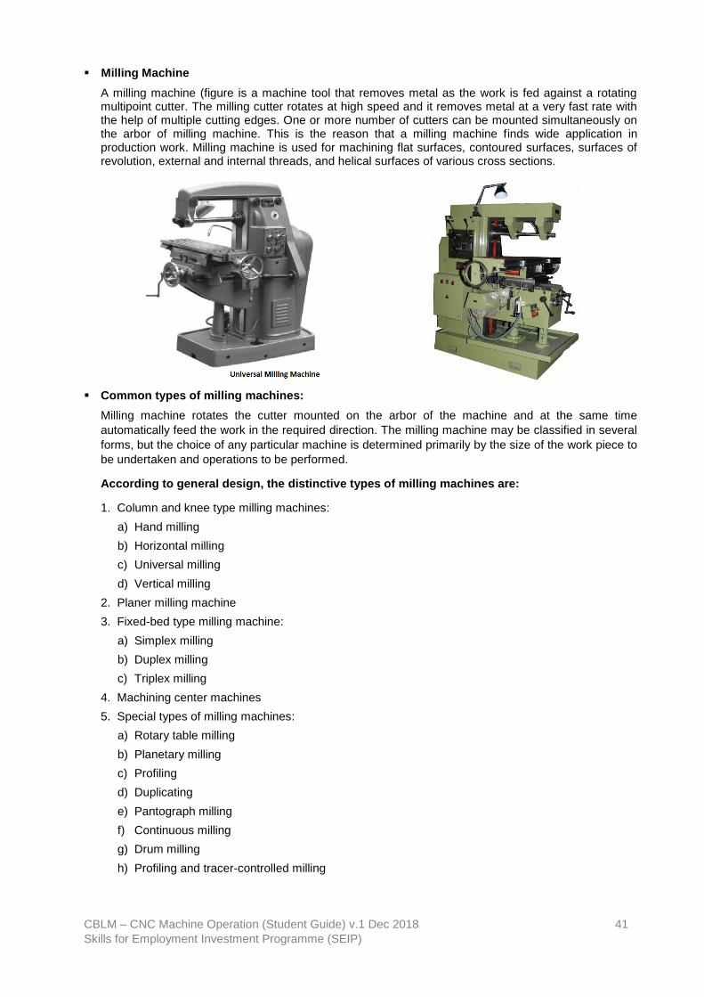
CBLM – CNC Machine Operation (Student Guide) v.1 Dec 2018 41
Skills for Employment Investment Programme (SEIP)
▪ Milling Machine
A milling machine (figure is a machine tool that removes metal as the work is fed against a rotating multipoint cutter. The milling cutter rotates at high speed and it removes metal at a very fast rate with the help of multiple cutting edges. One or more number of cutters can be mounted simultaneously on the arbor of milling machine. This is the reason that a milling machine finds wide application in production work. Milling machine is used for machining flat surfaces, contoured surfaces, surfaces of revolution, external and internal threads, and helical surfaces of various cross sections.
▪ Common types of milling machines:
Milling machine rotates the cutter mounted on the arbor of the machine and at the same time
automatically feed the work in the required direction. The milling machine may be classified in several
forms, but the choice of any particular machine is determined primarily by the size of the work piece to
be undertaken and operations to be performed.
According to general design, the distinctive types of milling machines are:
1. Column and knee type milling machines:
a) Hand milling
b) Horizontal milling
c) Universal milling
d) Vertical milling
2. Planer milling machine
3. Fixed-bed type milling machine:
a) Simplex milling
b) Duplex milling
c) Triplex milling
4. Machining center machines
5. Special types of milling machines:
a) Rotary table milling
b) Planetary milling
c) Profiling
d) Duplicating
e) Pantograph milling
f) Continuous milling
g) Drum milling
h) Profiling and tracer-controlled milling

CBLM – CNC Machine Operation (Student Guide) v.1 Dec 2018 42
Skills for Employment Investment Programme (SEIP)
▪ Principles of milling: In milling machine, the metal is cut by means of a rotating cutter having
multiple cutting edges. For cutting operation, the work piece is fed against the rotary cutter. As the
work piece moves against the cutting edges of milling cutter, metal is removed in form chips of
tracheid shape. Machined surface is formed in one or more passes of the work. The work to be
machined is held in a vice, a rotary table, a three-jaw chuck, an index head, between centers, in a
special fixture or bolted to machine table. The rotatory speed of the cutting tool and the feed rate of
the work piece depend upon the type of material being machined.
▪ Principal parts of a milling machine:
1. Base: It is a foundation member and it carries the column at its one end. In some machines, the base is hollow and serves as a reservoir for cutting fluid.
2. Column: The column is the main supporting member mounted vertically on the base. It is box
shaped, heavily ribbed inside and houses all the driving mechanism for the spindle and table feed. The front vertical face of the column is accurately machined and is provided with dovetail guide way for supporting the knee.
3. Knee: The knee is a rigid grey iron casting which slides up and down on the vertical ways of the
column face. An elevating screw mounted on the base is used to adjust the height of the knee and it also supports the knee.
4. Saddle: The saddle is placed on the top of the knee and it slides on guide ways set exactly at 90°
to the column face. The top of the saddle provides guide-ways for the table. 5. Table: The table rests on ways on the saddle and travels longitudinally. A lead screw under the
table engages a nut on the saddle to move the table horizontally by hand or power. In universal machines, the table may also be swiveled horizontally. For this purpose, the table is mounted on a circular base. The top of the table is accurately finished and T -slots are provided for clamping the work and other fixtures on it
6. Overhanging arm: It is mounted on the top of the column, which extends beyond the column
face and serves as a bearing support for the other end of the arbor. 7. Front brace: It is an extra support, which is fitted between the knee and the over-arm to ensure
further rigidity to the arbor and the knee. 8. Spindle: It is situated in the upper part of the column and receives power from the motor through
belts, gears and clutches and transmits it to the arbor. 9. Arbor: It is like an extension of the machine spindle on which milling cutters are securely
mounted and rotated. The arbors are made with taper shanks for proper alignment with the machine spindles having taper holes at their nose. The arbor assembly consists arbor, spindle, spacing collars, bearing bush, cutter, draw bolt, lock nut, key block, set screw.
▪ Milling Methods:
There are two distinct methods of milling classified as follows:
1. Up-milling or conventional milling

CBLM – CNC Machine Operation (Student Guide) v.1 Dec 2018 43
Skills for Employment Investment Programme (SEIP)
2. Down milling or climb milling.
Up-milling or conventional milling: In the up-milling or conventional milling, the metal is removed in form of small chips by a cutter rotating against the direction of travel of the work piece. In this type of milling, the chip thickness is minimum at the start of the cut and maximum at the end of cut. As a result, the cutting force also varies from zero to the maximum value per tooth movement of the milling cutter. The major disadvantages of up-milling process are the tendency of cutting force to lift the work from the fixtures and poor surface finish obtained. But being a safer process, it is commonly used method of milling.
Down-milling or climb milling: In this method, the metal is removed by a cutter rotating in the same direction of feed of the work piece. Chip thickness is maximum at the start of the cut and minimum in the end. In this method, there is less friction involved and consequently less heat is generated on the contact surface of the cutter and work piece. Climb milling can be used advantageously on many kinds of work to increase the number of pieces per sharpening and to produce a better finish. With climb milling, saws cut long thin slots more satisfactorily than with standard milling. Another advantage is that slightly lower power consumption is obtainable by climb milling, since there is no need to drive the table against the cutter.
SELF-CHECK QUIZ 2.2.1
Write true or false for the following statements:
1. In the up-milling or conventional milling, the metal is removed in form of small chips by a cutter rotating against the direction of travel of the work piece.
2. A milling machine is a machine tool that removes metal as the work is fed against a rotating multipoint cutter.
3. Milling machine is used for machining round surface.
4. The rotatory speed of the cutting tool and the feed rate of the work piece depend upon the type of material being machined.
5. Milling machine rotates the workpiece and at the same time automatically feed the arbor in the required direction.

CBLM – CNC Machine Operation (Student Guide) v.1 Dec 2018 44
Skills for Employment Investment Programme (SEIP)
LEARNING ACTIVITY 2.2.2
Learning Activity Resources/Special Instructions/References
Use milling accessories in accordance with the requirements of the operations
▪ Information Sheet: 2.2.2
▪ Self-Check Quiz: 2.2.2
▪ Answer Key: 2.2.2
INFORMATION SHEET 2.2.2
Learning Objective: to use milling accessories in accordance with the requirements of the operations.
▪ Milling Machine Accessories and Attachments:
1. Arbors: Milling machine cutters can be mounted on several types of holding device. The machinist must know the devices, and the purpose of each to make the most suitable tooling setup for the operation to be performed. Technically, an arbor is a shaft on which a cutter is mounted. For convenience, since there are so few types of cutter holders that are not arbors, we will refer to all types of cutter holding devices as arbors
Milling machine arbors are made in various lengths and in standard diameters of 7/8, 1, 1 1/4, and 1 1/2 inch. The shank is made to fit the ape red hole in the spindle, the other end is threaded. The threaded end may have left-handed or right-handed threads.
Arbors are supplied with one of three tapers to fit the milling machine spindle (figure 4 on the following page), the milling machines Standard taper, the Brown and Sharpe taper, and the Brown and Sharpe taper with tang.
The milling machine Standard taper is used on most machines of recent manufacture. It was originated and designed by the milling machine manufacturers to make removal of the arbor from the spindle much easier than will those of earlier design.
The Brown and Sharpe taper is found mostly on older machines. Adapters or collets are used to adapt these tapers to fit the machines whose spindles have milling machine Standard tapers.
The Brown and Sharpe taper with tang also is used on some of the older machines. The tang engages a slot in the spindle to assist in driving the arbor.
2. Standard Milling Machine Arbor: The standard milling machine arbor has a straight, cylindrical shape, with a Standard milling taper on the driving end and a threaded portion on the opposite end to receive the arbor nut. One or more milling cutters may be placed on the straight cylindrical shaft of the arbor and held in position by means of sleeves and an arbor nut. The Standard milling machine arbor is usually splined and has keys, used to lock each cutter to the arbor shaft. Arbors are supplied in various lengths and standard diameters.
The end of the arbor opposite the taper is supported by the arbor supports of the milling machine. One or more supports are used, depending on the length of the arbor and the degree of rigidity required. The end may be supported by a lathe center, bearing against the arbor nut or by a bearing surface of the arbor fitting inside a bushing of the arbor support. Journal bearings are placed over the arbor in place of sleeves where an intermediate arbor support is positioned.
The most common means of fastening the arbor in the milling machine spindle is by use of a draw-in bolt. The bolt threads into the taper shank of the arbor to draw the taper into the spindle and hold it in place. Arbors secured in this manner are removed by backing out the draw-in bolt and tapping the end of the bolt to loosen the taper.

CBLM – CNC Machine Operation (Student Guide) v.1 Dec 2018 45
Skills for Employment Investment Programme (SEIP)
Screw Arbor: Screw arbors are used to hold small cutters that have threaded holes. These arbors have a taper next to the threaded portion to provide alignment and support for tools that require a nut to hold them against a tapered surface. A right-hand threaded arbor must be used for right-hand cutters; a left-hand threaded arbor is used to mount left-hand cutters.
Slitting Saw Milling Cutter Arbor: The slitting saw milling cutter arbor is a short arbor having two flanges between which the milling cutter is secured by tightening a clamping nut. This arbor is used to hold the metal slitting saw milling cutters that are used for slotting, slitting, and sawing operations.
End Milling Cutter Arbor: The end milling cutter arbor has a bore in the end in which the straight shank end milling cutters fit. The end milling cutters are locked in place by means of a setscrew.
Shell End Milling Cutter Arbor: Shell end milling arbors are used to hold and drive shell end milling cutters. The shell end milling cutter is fitted over the short boss on the arbor shaft and is held against the face of the arbor by a bolt, or a retaining screw. The two lugs on the arbor fit slots in the cutter to prevent the cutter from rotating on the arbor during the machining operation. A special wrench is used to tighten and loosen a retaining screw/bolt in the end of the arbor.
Fly Cutter Arbor: The fly cutter arbor is used to support a single-edge lathe, shaper, or planer cutter bit, for boring and gear cutting operations on the milling machine. These cutters, which can be ground to any desired shape, are held in the arbor by a locknut. Fly cutter arbor shanks may have a Standard milling machine spindle taper, a Brown and Sharpe taper, or a Morse taper.
3. Collets and Spindles: Milling cutters that contain their own straight or tapered shanks are mounted to the milling machine spindle with collets or spindle adapters which adapt the cutter shank to the spindle.
Collets. Collets for milling machines serve to step up or increase the taper sizes so that small-shank tools can be fitted into large spindle recesses. They are similar to drilling machine sockets and sleeves except that their tapers are not alike. Spring collets are used to hold and drive straight-shanked tools. The spring collet chuck consists of a collet adapter, spring collets, and a cup nut. Spring collets are similar to lathe collets. The cup forces the collet into the mating taper, causing the collet to close on the straight shank of the tool. Collets are available in several fractional sizes.
Spindle Adapters. Spindle adapters are used to adapt arbors and milling cutters to the standard tapers used for milling machine spindles. With the proper spindle adapters, any tapered or straight shank cutter or arbor can be fitted to any milling machine, if the sizes and tapers are standard.
Indexing Fixture: The indexing fixture is an indispensable accessory for the milling machine. Basically, it is a device for mounting work pieces and rotating them a specified amount around the work piece's axis, as from one tooth space to another on a gear or cutter.
The index fixture consists of an index head, also called a dividing head, and a footstock, similar to the tailstock of a lathe. The index head and the footstock are attached to the worktable of the milling machine by T-slot bolts. An index plate containing graduations is used to control the rotation of the index head spindle. The plate is fixed to the index head and an index crank, connected to the index head spindle by a worm gear and shaft, is moved about the index plate. Work pieces are held between centers by the index head spindle and footstock. Work pieces may also be held in a chuck mounted to the index head spindle or may be fitted directly into the taper spindle recess of some indexing fixtures.

CBLM – CNC Machine Operation (Student Guide) v.1 Dec 2018 46
Skills for Employment Investment Programme (SEIP)
There are many variations of the indexing fixture. The name universal index head is applied to an index head designed to permit power drive of the spindle so that helixes may be cut on the milling machine.
High-Speed Milling Attachment. The rate of spindle speed of the milling machine may be increased from 1 1/2 to 6 times by the use of the high-speed milling attachment. This attachment is essential when using cutters and twist drills which must be driven at a high rate of speed in order to obtain an efficient surface speed. The attachment is clamped to the column of the machine and is driven by a set of gears from the milling machine spindle.
Vertical Spindle Attachment. This attachment converts the horizontal spindle of a horizontal milling machine to a vertical spindle. It is clamped to the column and driven from the horizontal spindle. It incorporates provisions for setting the bead at any angle, from the vertical to the horizontal, in a plane at right angles to the machine spindle. End milling and face milling operations are more easily accomplished with this attachment, due to the fact that the cutter and the surface being cut are in plain view.
Universal Milling Attachment. This device is similar to the vertical spindle attachment but is more versatile. The cutter head can be swiveled to any angle in any plane, whereas the vertical spindle attachment only rotates in one plane from the horizontal to the vertical.
Circular Milling Attachment. This attachment consists of a circular worktable containing T-slots for mounting work pieces. The circular table revolves on a base attached to the milling machine worktable. The attachment can be either hand or power driven, being connected to the table drive shaft if power driven. It may be used for milling circles, arcs, segments, and circular slots, as well as for slotting internal and external gears. The table of the attachment is divided in degrees.
Offset Boring Head. The offset boring head is an attachment that fits to the milling machine spindle and permits a single-edge cutting tool, such as a lathe cutter bit, to be mounted off-center on the milling machine. Work pieces can be mounted in a vise attached to the worktable and can be bored with this attachment.
4. Mounting and Indexing Work
An efficient and positive method of holding work pieces to the milling machine table is essential if the machine tool is to be used to advantage. Regardless of the method used in holding, there are certain factors that should be observed in every case. The work piece must not be sprung in clamping; it must be secured to prevent it from springing or moving away from the cutter; and it must be so aligned that it may be correctly machined.
Milling machine worktables are provided with several T-slots, used either for clamping and locating the work piece itself or for mounting various holding devices and attachments. These T-slots extend the length of the table and are parallel to its line of travel. Most milling machine attachments, such as vises and index fixtures, have keys or tongues on the underside of their bases so that they may be located correctly in relation to the T-slots.
5. Methods of mounting work pieces
Clamping a Work piece To the Table. When clamping work pieces to the worktable of the milling machine, the table and work piece should be free from dirt and burrs. Work pieces having smooth machined surfaces may be clamped directly to the table, provided the cutter does not come in contact with the table surface during the machining operation. When clamping work pieces with unfinished surfaces in this way, the table face should be protected by pieces of soft metal. Clamps should be placed squarely across the work piece to give a full bearing surface. These clamps are held by T-slot bolts inserted in the T-slots of the table. Clamping bolts should be placed as near to the work piece as possible. When it is necessary to place a clamp on an overhanging part of the work piece, a support should be provided between the overhang and the table, to prevent springing or possible breakage. A stop should be placed at the end of the work piece where it will receive the thrust of the cutter when heavy cuts are being taken.
Clamping a Work piece to the Angle Plate. Work pieces clamped to the angle plate may be machined with surfaces parallel, perpendicular, or at an angle to a given surface. When using this method of holding a work piece precautions should be taken, similar to those mentioned in (1) above for clamping the work piece-directly to the table. Angle plates may be of either the adjustable or the nonadjustable type and are generally held in alignment by means of keys or tongues that fit into the table T-slots.

CBLM – CNC Machine Operation (Student Guide) v.1 Dec 2018 47
Skills for Employment Investment Programme (SEIP)
Clamping Work pieces in Fixtures. Fixtures are generally used in production work where a number of identical pieces are to be machined. The design of the fixture is dependent upon the shape of the piece and the operations to be performed. Fixtures are always constructed to secure maximum clamping surfaces and are built to use a minimum number of clamps or bolts, in order to reduce the time required for setting up the work piece.
Fixtures should always be provided with keys to assure positive alignment with the table T-slots.
Holding Work pieces Between Centers. The indexing fixture is used to support work pieces which are centered on both ends. When the piece has been previously reamed or bored, it may be pressed upon a mandrel and then mounted between the centers, as with a lathe.
There are two types of mandrels that may be used for mounting.
Work pieces between centers. The solid mandrel is satisfactory for many operations, while the mandrel having a tapered shank is preferred when fitting the work piece into the indexing head of the spindle.
A jack screw is used to prevent springing of long slender work pieces held between centers, or work pieces that extend some distance from the chuck.
Work pieces mounted between centers are fixed to the index head spindle by means of a lathe dog. The bent tail of the dog should be fastened between the setscrews provided in the driving center clamp in such a manner as to avoid backlash and prevent springing the mandrel. When milling certain types of work piece, a milling machine dog may be used to advantage. The tail of the dog is held in a flexible ball joint which eliminates springing or shaking of the work piece and/or the dog. The flexible ball joint allows the tail of the dog to move in a radius along the axis of the workpiece, making it particularly useful in the rapid milling of tapers.
Holding Work pieces in a Chuck. Before screwing the chuck to the index head spindle, it should be cleaned, and all burrs removed from the spindle or the chuck. Burrs may be removed with a smooth cut, three cornered file or scraper. Cleaning should be accomplished with a piece of spring-steel wire bent and formed to fit the angle of the threads, or by the use of compressed air. The chuck should not be tightened on the spindle so tightly that a wrench or bar is required to remove it. Cylindrical work pieces, held in the universal chuck, may be checked for trueness by using a test indicator mounted on a base which rests on the milling machine. The indicator point should contact the circumference of small diameter work pieces, or the circumference and exposed face of large diameter pieces. While checking for trueness, the work piece should be revolved by rotating the index head spindle.
Holding Work pieces in the Vice. Three types of vices are manufactured in various sizes for holding milling machine work pieces. These vices have locating keys or tongues on the underside of their bases so they may be located correctly in relation to the T-slots on the milling machine table.
The plain vice, similar to the machine table vice, is used for milling straight work pieces; it is bolted to the milling machine table at right angles or parallel to the machine arbor.
The swivel vice can be rotated and contains a scale graduated in degrees at its base to facilitate milling work pieces at any angle on a horizontal plane. This vice is fitted into a graduated circular base fastened to the milling machine table and located by means of keys placed in the T-slots. By loosening the bolts, which clamp the vice to its graduated base, the vice may be moved to hold the work piece at any angle in a horizontal plane. To set a swivel vice accurately with the machine spindle, a test indicator should be clamped to the machine arbor and a check made to determine the setting by moving either the transverse or the longitudinal feeds, depending upon the position of the vice jaws. Any deviation as shown by the test indicator should be corrected by swiveling the vice on its base.
The universal vice is constructed to allow it to be set at any angle, either horizontally or vertically, to the axis of the milling machine spindle. Due to the flexibility of this vice, it is not adaptable for heavy milling.
When rough or unfinished work pieces are to be vice mounted, a piece of protecting material should be placed between the vice jaws and the work piece.
When it is necessary to position a work piece above the vice jaws, parallels of the same size and of the proper height should be used. These parallels should only be high enough to allow the

CBLM – CNC Machine Operation (Student Guide) v.1 Dec 2018 48
Skills for Employment Investment Programme (SEIP)
required cut, as excessive raising reduces the holding ability of the jaws. When holding a work piece on parallels, a soft lead hammer should be used to tap the top surface of the piece after the vice jaws have been tightened. This tapping should be continued until the parallels cannot be moved by hand. After once set, additional tightening tends to raise the work off the parallels
If the work piece is so thin that it is impossible to let it extend over the top of the vice, hold down straps, are generally used. These straps are hardened pieces of steel, having one vertical side tapered to form an angle of about 92 degrees with the bottom side and the other vertical side tapered to a narrow edge. By means of these tapered surfaces, the work piece is forced downward on to the parallels, holding them firmly and leaving the top surface of the work piece fully exposed to the milling cutter.
Whenever possible, the work piece should be clamped in the center of the vice jaws. However, when necessary to mill a short work piece which must be held at the end of the vice, a spacing block of the same thickness as the piece should be placed at the opposite ends of the jaws. This will avoid strain on the movable jaw and prevent the piece from slipping.
SELF-CHECK QUIZ 2.2.2
Write true or false for the following statements:
1. Milling machine worktables are provided with several T-slots.
2. When clamping work pieces to the worktable of the milling machine, the table and work piece should be free from fixture.
3. Jack screw is used to prevent springing of long slender work pieces held between centers, or work pieces that extend some distance from the chuck.
4. Milling machine worktables are provided with several T-slots, used either for clamping and locating the work piece itself or for mounting various holding devices and attachments.
5. When rough or unfinished work pieces are to be vice mounted, a piece of protecting material should be placed between the vice jaws and the work piece to eliminate marring the jaws.

CBLM – CNC Machine Operation (Student Guide) v.1 Dec 2018 49
Skills for Employment Investment Programme (SEIP)
LEARNING ACTIVITY 2.2.3
Learning Activity Resources/Special Instructions/References
Select cutting speed and feed rate in accordance with the job specifications
▪ Information Sheet: 2.2.3
▪ Self-Check Quiz: 2.2.3
▪ Answer Key: 2.2.3
INFORMATION SHEET 2.2.3
Learning Objective: to select cutting speed and feed rate in accordance with the job specifications.
Speeds for Milling Cutters:
General. The speed of a milling cutter is the distance in feet per minute that each tooth travels as it cuts its chips. The number of spindle revolutions per minute necessary to give a desired peripheral speed on the size of the milling cutter. The best speed is determined by the type of material being cut and the size and type of cutter used. The smoothness of the finish desired and the power available are other factors relating to the cutter speed.
Selecting Proper Cutting Speed
a) The approximate values given in table 1 on the following page may be used as a guide for selecting the proper cutting speed. If the operator finds that the machine, the milling cutter, or the work piece cannot be handled suitably at these speeds, immediate readjustment should be made.
b) Table 1 lists speeds for high-speed steel milling cutters. If carbon steel cutters are used, the speed should be about one-half the speed recommended in the table. If carbide-tipped cutters are used, the speed can be doubled.
c) If a plentiful supply of cutting oil is applied to the milling cutter and the work piece, the speeds can be increased from 50 to 100 percent.
d) For roughing cuts, a moderate speed and coarse feed give best results; for finishing cuts, the best practice is to reverse these conditions, using a higher speed and a lighter cut.
MILLING MACHINE CUTTING SPEEDS FOR HIGH-SPEED STEEL MILLING CUTTERS

CBLM – CNC Machine Operation (Student Guide) v.1 Dec 2018 50
Skills for Employment Investment Programme (SEIP)
Speed Calculation:
(a) The formula for calculating spindle speed in revolutions per minute is as follows:
Where, rpm = spindle speed (in revolution per minute) cs = cutting speed of milling cutter (in surface feet per minute) D = diameter of milling cutter (in inches). (b) The above Table is provided to facilitate spindle speed computations for standard cutting speeds and standard milling cutters. Feeds for Milling:
The rate of feed, or the speed at which the work piece passes the cutter, determines the time required for cutting a job. In selecting the feed, there are several factors which should be considered.
(a) Forces are exerted against the work piece, the cutter, and their holding devices during the cutting process. The force exerted varies directly with the amount of metal removed and can be regulated by the feed and the depth of cut. Therefore, the correct amount of feed and depth of cut are interrelated, and in turn are dependent upon the rigidity and power of the machine. Milling machines are limited by the power that they can develop to turn the cutter and the amount of vibration they can resist when using coarse feeds and deep cuts.
(b) The feed and depth of cut also depend upon the type of milling cutter being used. For example, deep cuts or coarse feeds should not be attempted when using a small diameter end milling cutter, as such an attempt would spring or break the cutter. Coarse cutters with strong cutting teeth can be fed at a faster rate because the chips may be washed out more easily by the cutting oil.
(c) Coarse feeds and deep cuts should not be used on a frail work piece, or on a piece that is mounted in such a way that its holding device is not able to prevent springing or bending.
(d) The degree of finish required often determines the amount of feed.
(e) Using a coarse feed, the metal is removed more rapidly but the appearance and accuracy of the surface produced may not reach the standard desired for the finished product. Because of this, finer feeds and increased speeds are used for finer, more accurate finishes. Most mistakes are made through.
(f) Over speeding, under speeding, and overfeeding. Over speeding may be detected by the occurrence of a squeaking, scraping sound. If vibration (referred to as "chattering") occurs in the milling machine during the cutting process, the speed should be reduced, and the feed increased. Too much cutter clearance, a poorly supported work piece, or a badly worn machine gear are common causes of "chattering".
Typical Feeds:
(a) Feed for milling cutters will generally run from 0.002 to 0.250 inch per cutter revolution, depending upon the diameter of the cutter, the kind of material, the width and depth of the cut, the size of the work piece, and the condition of the machine.
(b) Good finishes may be obtained using a 3-inch plain milling cutter at a 40 feet per minute speed, with a feed of 0.040-inch per cutter revolution.
Direction of Feed:
(a) It is usually regarded as standard practice to feed the work piece against the milling cutter (figure 12 on the following page). When the piece is fed against the milling cutter, the teeth cut under any scale on the work piece surface and any backlash in the feed screw is taken up by the force of cut.
(b) As an exception to this recommendation, it is advisable to feed with the milling cutter (figure 12), when cutting off stock, or when milling comparatively deep or long slots.

CBLM – CNC Machine Operation (Student Guide) v.1 Dec 2018 51
Skills for Employment Investment Programme (SEIP)
(c) The direction of cutter rotation is related to the manner in which the work piece is held. The cutter should rotate so that the piece springs away from the cutter; then there will be no tendency for the force of the cut to loosen the work piece. No milling cutter should be rotated backward as this will break the teeth. If it is necessary to stop the machine during a finishing cut, the power feed should never be thrown out, nor should the work piece be feedback under the cutter, unless the cutter is stopped, or the work piece lowered. Never change feeds while the cutter is rotating.
SELF-CHECK QUIZ 2.2.3
Write true or false for the following statements:
1. Plain milling operation produces plain surfaces on the work piece. Feed and depth of cut are selected, rotating milling cutter is moved from one end of the work piece to other end to complete the one pairs of plain milling operation.
2. Do not select a milling cutter of larger diameter than is necessary.
3. Use good judgment and common sense in planning every job, and profit by previous mistakes.
4. It is usually regarded as standard practice to feed the work piece towards the milling cutter.
5. Face milling operation produces flat surface at the face on the work piece. This surface is perpendicular to the surface prepared in plain milling operation.

CBLM – CNC Machine Operation (Student Guide) v.1 Dec 2018 52
Skills for Employment Investment Programme (SEIP)
Learning Outcome 2.3 - Perform Basic Milling Machine Operations
Contents:
▪ Perform basic milling operations to produce component
▪ Check and measure workpiece in conformance to specification using appropriate methods, measuring tools and equipment
Assessment criteria:
▪ Basic milling operations are performed to produce component.
▪ Corrective measures/adjustments are performed.
▪ Workpiece is checked and measured in conformance to specification using appropriate methods, measuring tools and equipment.
Resources required:
Students/trainees must be provided with the following resources:
▪ Workplace (simulated or actual)
▪ Relevant drawings, manuals, codes, standards and reference material
▪ Milling machine and accessories, cutting tools appropriate to processes or activities
▪ Stationery
▪ Instruction sheet/manual
▪ Personal protective equipment (PPE)
LEARNING ACTIVITY 2.3.1
Learning Activity Resources/Special Instructions/References
Perform basic milling operations to produce component
▪ Information Sheet: 2.3.1
▪ Self-Check Quiz: 2.3.1
▪ Answer Key: 2.3.1
INFORMATION SHEET 2.3.1
Learning Objective: to perform basic lathe operations to produce component.

CBLM – CNC Machine Operation (Student Guide) v.1 Dec 2018 53
Skills for Employment Investment Programme (SEIP)
Milling Machine Operations: The milling machine is one of the most versatile metalworking machines in a shop. It is capable of performing simple operations, such as milling a flat surface or drilling a hole, or more complex operations, such as milling helical gear teeth. It would be impractical to attempt to discuss all of the operations that a milling machine can do. The success of any milling operation depends to a great extent upon judgment in setting up the job, selecting the proper cutter, and holding the cutter by the best means. Even though we will discuss only the more common operations, the machinist will find that by using a combination of operations, he will be able to produce a variety of work projects. Some fundamental practices have been proved by experience to be necessary for good results on all jobs. Some of these practices are mentioned below:
(a) Before setting up a job, be sure that the work piece, the table, the taper in the spindle, and arbor or cutter shank, are all clean and free from chips, nicks, or burrs.
(b) Set up every job as close to the milling machine spindle as the circumstances permit.
(c) Do not select a milling cutter of larger diameter than is necessary.
(d) Keep milling cutters sharp at all times.
(e) Do not change feeds or speeds while the milling machine is in operation.
(f) Always lower the table before backing the work piece under a revolving milling cutter.
(g) Feed the work piece in a direction opposite to the rotation of the milling cutter, except when milling long or deep slots or when cutting off stock.
(h) Never run a milling cutter backwards.
(i) When using clamps to secure the work pieces, be sure that they are tight and that the work piece is held so that it will not spring or vibrate while it is being cut.
(j) Use a recommended cutting oil liberally.
(k) Keep chips away from the work piece; brush them out of the way by any convenient means, but do not do so by hand or with waste.
(l) Use good judgment and common sense in planning every job, and profit by previous mistakes.
Plain Milling Operation: This is also called slab milling. This operation produces flat surfaces on the work piece. Feed and depth of cut are selected, rotating milling cutter is moved from one end of the work piece to other end to complete the one pairs of plain milling operation.
Face Milling: This operation produces flat surface at the face on the work piece. This surface is perpendicular to the surface prepared in plain milling operation. This operation is performed by face milling cutter mounted on stub arbor of milling machine. Depth of cut is set according to the need and cross feed is given to the work table.
Side Milling Operation: This operation produces flat and vertical surfaces at the sides of the work piece. In this operation depth of cut is adjusted by adjusting vertical feed screw of the work piece.
Straddle Milling Operation: This is similar to the side milling operation. Two side milling cutters are mounted on the same arbor. Distance between them is so adjusted that both sides of the work piece can be milled simultaneously. Hexagonal bolt can be produced by this operation by rotating the work piece only two times as this operation produces two parallel faces of bolt simultaneously.
Angular Milling Operation: Angular milling operation is used to produce angular surface on the work piece. The produced surface makes an angle with the axis of spindle which is not right angle. Production of ‘V‟ shaped groove is the example of angular milling operation.
Gang Milling Operation: As the name indicates, this operation produces several surfaces of a work piece simultaneously using a gang of milling cutters. During this operation, the work piece mounted on the table is fed against the revolving milling cutters.
Form Milling: This operation produces irregular contours on the work surface. These irregular contours may be convex, concave, or of any other shape. This operation is done comparatively at very low cutter speed than plain milling operation.
Profile Milling: In this operation a template of complex shape or master die is used. A tracer and milling cutter are synchronized together with respect to their movements. Tracer reads the template or master

CBLM – CNC Machine Operation (Student Guide) v.1 Dec 2018 54
Skills for Employment Investment Programme (SEIP)
die and milling cutter generates the same shape on the work piece. Profile milling is an operation used to generate shape of a template or die.
End Milling: End milling operation produces flat vertical surfaces, flat horizontal surfaces and other flat surfaces making an angle from table surface using milling cutter named as end mill. This operation is preferably carried out on vertical milling machine.
Saw Milling: Saw milling operation produces narrow slots or grooves into the work piece using saw milling cutter. This operation is also used to cut the work piece into two equal or unequal pieces which cut is also known as “parting off”.
Slot Milling Operation: The operation of producing keyways, grooves, slots of varying shapes and sizes is called slot milling operation. Slot milling operation can use any type of milling cutter like plain milling cutter, metal slitting saw or side milling cutter. Selection of a cutter depends upon type and size of slot or groove to be produced.
Gear Cutting Operation: The operation of gear cutting is cutting of equally spaced, identical gear teeth on a gear blank by handling it on a universal dividing head and then indexing it. The cutter used for this operation is cylindrical type or end mill type. The cutter selection also depends upon tooth profile and their spacing.
Helical Milling Operation: Helical milling produces helical flutes or grooves on the periphery of a cylindrical or conical work piece. This is performed by swiveling the table to the required helix angle, then rotating and feeding the work piece against revolving cutting edges of milling cutter. Helical gears and drills and reamers are made by this operation.
Cam Milling Operation: The operation cam milling is used to produce the cam on milling machine. In this operation cam blank is mounted at the end of the dividing head spindle and the end mill is held in the vertical milling attachment.
Thread Milling Operation: The operation thread milling produces threads using thread milling centers. This operation needs three simultaneous movements revolving movement of cutter, simultaneous longitudinal movement of cutter, feed movement to the work piece through table. For each thread, the revolving cutter is fed longitudinal by a distance equal to pitch of the thread. Depth of cut is normally adjusted equal to the full depth of threads.
SELF-CHECK QUIZ 2.3.1
Write true or false for the following statements:
1. Face milling operation produces flat surface at the face on the work piece. This surface is perpendicular to the surface prepared in plain milling operation.
2. Side milling operation produces plain and vertical surfaces at the sides of the work piece.
3. Straddle milling operation is two or more side milling cutters are mounted on the same arbor.
4. Gang milling operation the name indicates, this operation produces several surfaces of a work piece simultaneously using a gang of milling cutters.
5. Production of ‘V‟ shaped groove is the example of angular milling operation.
LEARNING ACTIVITY 2.3.2
Learning Activity Resources/Special Instructions/References
Check and measure workpiece in conformance to specification using appropriate methods, measuring tools and equipment
▪ Information Sheet: 2.3.2
▪ Self-Check Quiz: 2.3.2
▪ Answer Key: 2.3.2

CBLM – CNC Machine Operation (Student Guide) v.1 Dec 2018 55
Skills for Employment Investment Programme (SEIP)
INFORMATION SHEET 2.3.1
Learning Objective: to check and measure workpiece in conformance to specification using appropriate methods, measuring tools and equipment.
A vernier scale is a visual aid to take an accurate measurement reading between two graduation markings on a linear scale by using mechanical interpolation; thereby increasing resolution and reducing measurement uncertainty by using Vernier acuity to reduce human estimation error.
A micrometre, sometimes known as a micrometre screw gauge, is a device incorporating a calibrated screw widely used for accurate measurement of components in mechanical engineering and machining as well as most mechanical trades, along with other metrological instruments such as dial, vernier, and digital callipers.
A thread gauge, also known as a screw gauge or pitch gauge, is used to measure the pitch or lead of a screw thread. Thread pitch gauges are used as a reference tool in determining the pitch of a thread that is on a screw or in a tapped hole.
SELF-CHECK QUIZ 2.3.2
Write true or false for the following statements:
1. A positive allowance will always result in a clearance fit.
2. Precision of micrometre screw gauge is 0.1 mm.
3. A thread is called a left-hand thread if a nut when turned in clockwise direction screws on a bolt.
4. The distance moved by a nut or a bolt in axial direction in one complete revolution called pitch.
5. A metric measurement lathe has a quick-change gear box used to set the proper screw pitch in inch.

CBLM – CNC Machine Operation (Student Guide) v.1 Dec 2018 56
Skills for Employment Investment Programme (SEIP)
JOB SHEET 2
Job Title: To make a a hexagon from round rod as per the given sketch and dimension by using a different type of milling cutter.
plain, step, curve, taper, ball and thread cutting operations.
Personal protective equipment:
Gloves, dust mask, safety shoes, hard hat, belt/body harness, goggles, working clothes, apron
Materials: Mild steel rod of 50 mm Ø and length 50 mm.
Tools and equipment:
Steel rule, vernier caliper, jenny caliper (odd leg caliper), chuck key, surface gauge, center bit, power hacksaw, spanners, milling cutter.
Milling Operations: Slab and end milling.
Procedure: 1. Cut mild steel rod of 50 mm Ø in 50 mm length from long bar by using power hack saw or ordinary hacksaw.
2. The given work piece is measured for its initial dimensions.
3. With the help of scriber, mark the hexagon dimensions in the work piece.
4. Fix the work piece in the vice of the milling machine.
5. After fixing the work piece and the milling tool, allow the spindle to rotate.
6. Start the milling process by giving the required depth by lowering the tool.
7. Slowly increase the depth of cut and repeat the procedure to make the hexagon shape.
8. Check the dimensions when doing the work consecutively and complete the job.
9. Clean the lathe machine and remove all chips from the tray.
All dimensions are in mm

CBLM – CNC Machine Operation (Student Guide) v.1 Dec 2018 57
Skills for Employment Investment Programme (SEIP)
REVIEW OF COMPETENCY
Final Checklist
(for the performance criteria of the module Performing Distempering)
Performance Criteria Yes No
1. Drawings are interpreted to grind tools confirming to the specifications.
2. Tool holding devices are selected according to the requirements of the operation.
3. Cutting tools are selected according to requirements of the milling operation.
4. Appropriate types of milling machine are selected for different milling operations.
5. Milling accessories are used in accordance with the requirements of the operations.
6. Cutting speed, feed and depth of cut are selected in accordance with the job specifications.
7. Job materials are selected and collected in accordance with the job specifications.
8. Cutting tools are selected in accordance with the requirements of the operation.
9. Sequence of operation is determined to produce products to the specifications.
10. Cutting speed, feed and depth of cut are calculated in accordance with the job requirement.
11. Machine performance is checked in conformance with the job requirement.
12. Coolant is applied to prevent over heating of work piece and cutting tool.
13. Basic milling operations are performed to produce component.
14. Corrective measures/adjustments are performed if necessary.
15. Workpiece is checked and measured in conformance to specification using appropriate methods, measuring tools and equipment.
Now I feel ready to undertake my formal competency assessment.
Signed: _________________________
Date: _________________________

CBLM – CNC Machine Operation (Student Guide) v.1 Dec 2018 58
Skills for Employment Investment Programme (SEIP)
ANSWER KEYS
ANSWER KEY 2.1.1
1. False 2. True 3. True 4. True 5. False
ANSWER KEY 2.1.2
1. True 2. True 3. True 4. False 5. True
ANSWER KEY 2.1.3
1. False 2. True 3. False 4. True 5. True
ANSWER KEY 2.2.1
1. True 2. True 3. False 4. True 5. False
ANSWER KEY 2.2.2
1. True 2. False 3. True 4. True 5. False
ANSWER KEY 2.2.3
1. False 2. True 3. True 4. False 5. True
ANSWER KEY 2.3.1
1. True 2. True 3. False 4. True 5. True

CBLM – CNC Machine Operation (Student Guide) v.1 Dec 2018 59
Skills for Employment Investment Programme (SEIP)
ANSWER KEY 2.3.2
1. True 2. False 3. False 4. True 5. True

CBLM – CNC Machine Operation (Student Guide) v.1 Dec 2018 60
Skills for Employment Investment Programme (SEIP)
Module 3: Carry out CNC lathe machine operations
MODULE CONTENT
Module Descriptor: This module covers the knowledge, skills and attitudes required to carry
out CNC lathe machine operations. It specifically includes setting-up
CNC lathe machine, downloading/inputting program, cutting
model/sample work piece, performing CNC lathe machine operation,
checking and measuring work piece and maintaining CNC lathe
machine, tools and equipment.
Nominal Duration: 60 hours
LEARNING OUTCOMES:
Upon completion of the module, the student/trainee should be able to:
3.1. Set-up CNC lathe machine, workpiece and cutting tools
3.2. Cut model/sample workpiece
3.3. Perform CNC lathe machine operations
3.4. Maintain CNC lathe machine, tools and equipment
PERFORMANCE CRITERIA:
1. Oil, coolant, air and hydraulic is checked in accordance with manufacturer’s specification.
2. Machine zero point is set to the required position.
3. Cutting tools are set according to required sequence of operations.
4. Work holding and clamping devices are set and tightened according to standard operating procedures.
5. Dry run is performed in accordance with the desired tool movement.
6. Work piece is cut as programmed and is checked and measured using appropriate measuring instruments.
7. Program is edited and tool parameters are corrected/adjusted as required.
8. Work piece is mounted or set in accordance with standard operating procedures.
9. CNC lathe operations are performed to produce component as programmed.
10. Work piece is checked and measured in conformance to specification using appropriate methods, measuring tools and equipment.
11. Proper shutdown is carried out in accordance with standard operating procedures.
12. Ensuring security of data, including regular back-ups and virus checks are implemented in accordance with standard operating procedures.
13. Basic file maintenance procedures are implemented in line with the standard operating procedures.
14. CNC lathe machine is cleaned and maintained with the standard operating procedures.
15. Tools, equipment and materials are stored safely in appropriate location according to standard work place procedures.
CBLM – CNC Machine Operation (Student Guide) v.1 Dec 2018 61
Skills for Employment Investment Programme (SEIP)
Learning Outcome 3.1 - Set-Up CNC Lathe Machine, Workpiece and Cutting Tools
Contents:
▪ Check oil, coolant, air and hydraulic in accordance with manufacturer’s specification
▪ Set machine zero point to the required position
▪ Set cutting tools according to required sequence of operations
▪ Set work holding and clamping devices and tightened according to standard operating procedures
Assessment criteria:
▪ Oil, coolant, air and hydraulic is checked in accordance with manufacturer’s specification.
▪ Machine zero point is set to the required position.
▪ Cutting tools are set according to required sequence of operations.
▪ Work holding and clamping devices are set and tightened according to standard operating procedures.
Resources required:
Students/trainees must be provided with the following resources:
▪ Workplace (simulated or actual)
▪ Relevant drawings, manuals, codes, standards and reference material
▪ CNC lathe machine, cutting tools, clamping devices and accessories
▪ Stationery
▪ Instruction sheet/manual
▪ Personal protective equipment (PPE)
LEARNING ACTIVITY 3.1.1
Learning Activity Resources/Special Instructions/References
Check oil, coolant, air and hydraulic in accordance with manufacturer’s specification
▪ Information Sheet: 3.1.1
▪ Self-Check Quiz: 3.1.1
▪ Answer Key: 3.1.1

CBLM – CNC Machine Operation (Student Guide) v.1 Dec 2018 62
Skills for Employment Investment Programme (SEIP)
INFORMATION SHEET 3.1.1
Learning Objective: to check oil, coolant, air and hydraulic in accordance with manufacturer’s specification.
1. Check the hydraulic pressure to make sure it’s at 4.5 MPa.
2. Check the hydraulic fluids to make sure they’re at the right operating level.
3. Check to make sure the chuck pressure is at the right operating pressure and grease chuck according to manufacturer's recommendation.
4. Make sure the way lube level is at the right operating level and replenish if needed.
5. If your CNC machine has a cooling system, make sure the cooling unit level is at the right operating level.
6. Clean the chips out of the chip pan.
7. Clean off the window of the door and the light so you can see inside your machine.
8. Wipe down any stainless-steel way covers and lubricate them with hydraulic oil, so they move smoothly.
9. Check and grease the chain on the chip conveyor.
10. Check and clean the filters on the coolant tank.
SELF-CHECK QUIZ 3.1.1
Write true or false for the following statements:
1. For CNC machining skilled part programmers are needed.
2. CNC machine has a cooling system, make sure the cooling unit level is at the right operating level.
3. Chuck pressure is at the right operating pressure and grease chuck according to manufacturer's recommendation.
4. Avoid using compressed air to clean chips from the milling machine because it gives a poor finish to the job.
5. Before operating a lathe machine, you should remove all safety guards.
LEARNING ACTIVITY 3.1.2
Learning Activity Resources/Special Instructions/References
Set machine zero point to the required position ▪ Information Sheet: 3.1.2
▪ Self-Check Quiz: 3.1.2
▪ Answer Key: 3.1.2
INFORMATION SHEET 3.1.2
Learning Objective: to set machine zero point to the required position.

CBLM – CNC Machine Operation (Student Guide) v.1 Dec 2018 63
Skills for Employment Investment Programme (SEIP)
1. Machine zero point is also called as home position or machine reference point.
2. Change the machine mode from 'AUTO' to the 'MANUAL'.
3. Set a positive feed rate for the turret.
4. Change the turret position for setting machine zero.
5. Jog the turret to the extreme position along X axis.
6. After that, Jog the turret to the extreme position along Z axis.
7. Go to 'PARAMETER SET' window for setting machine zero.
8. Press calculate button, machine will calculate the current co-ordinate as machine zero.
9. Return from the 'MANUAL' mode to 'AUTO' mode.
SELF-CHECK QUIZ 3.1.2
Write true or false for the following statements:
1. Machine zero point is also called as home position of the CNC machine.
2. Tool turret position can be changed in ‘AUTO’ mode.
3. Feed rate of the tool turret must be kept zero.
4. Turret should be taken to the extreme position of X and Z axes.
5. Before operating a milling machine, you should remove all safety guards.
LEARNING ACTIVITY 3.1.3
Learning Activity Resources/Special Instructions/References
Set cutting tools according to required sequence of operations
▪ Information Sheet: 3.1.3
▪ Self-Check Quiz: 3.1.3
▪ Answer Key: 3.1.3
INFORMATION SHEET 3.1.3
Learning Objective: to set cutting tools according to required sequence of operations.
1. Change the machine mode from 'AUTO' to the 'MANUAL'.
2. Set a positive feed rate for the turret.
3. Jog the turret to the extreme position along X axis or Z axis or both.
4. Mount a tool holder in the tool post turret and then Insert the proper cutting tool into the tool holder.
5. Turn the tool post turret to next tool position.
6. Repeat step 4 for setting each tool to the tool post turret according to required sequence of operation.
7. Press MANUAL mode button and start spindle again.
8. Bring the turret near the job and do turning operation.
9. Retract the turret along Z direction and Stop spindle.
10. Press TOOL DATA SET button, If the Z-value is not zero, then manually set it zero.

CBLM – CNC Machine Operation (Student Guide) v.1 Dec 2018 64
Skills for Employment Investment Programme (SEIP)
11. To set X value of the master tool, toggle to the data. Press CAL to calculate and enter the job diameter that is to be measured by outer calliper, then press WRITE button.
12. Do the same for every tool.
SELF-CHECK QUIZ 3.1.3
Write true or false for the following statements:
1. It is not required to take the turret to machine zero.
2. Tool insert are attached to the tool holder.
3. Before tool data set turning operation is required.
4. All the tools are mounted on the turret keeping it in fixed position.
5. Mount the tool according to the size of the tool.
LEARNING ACTIVITY 3.1.4
Learning Activity Resources/Special Instructions/References
Set work holding and clamping devices and tightened according to standard operating procedures
▪ Information Sheet: 3.1.4
▪ Self-Check Quiz: 3.1.4
▪ Answer Key: 3.1.4
INFORMATION SHEET 3.1.4
Learning Objective: to set work holding and clamping devices and tightened according to standard operating procedures.
1. Find out the size and type of work to be machined.
2. Decide particular operation that needs to be done.
3. Determine the accuracy level is needed for a job.
4. Select appropriate work holding and clamping devices according to the previous three decisions.
5. Clean the spindle inner part.
6. Set 3 or 4 jaw self-centring chuck to the spindle of the CNC machine.
7. Measure the work piece diameter.
8. Set open and close diameter of the chuck so that it can hold the work piece tightly.
9. Rotate the chuck and find, if there is any vibration happened.
10. Set the tail stock and set the range of tailstock to adjust the work piece tightly.
11. Check that the live centre in the tail stock is running true.
12. If it is not running true, remove the centre, clean all surfaces, and replace the centre.

CBLM – CNC Machine Operation (Student Guide) v.1 Dec 2018 65
Skills for Employment Investment Programme (SEIP)
SELF-CHECK QUIZ 3.1.4
Write true or false for the following statements:
1. The size and type of work is not important for selecting work holding device.
2. Some work holding devices are more accurate than others.
3. Self-centring chuck is a tool holding device.
4. For Long work piece tailstock is needed.
5. Live centre is used for reducing the friction.

CBLM – CNC Machine Operation (Student Guide) v.1 Dec 2018 66
Skills for Employment Investment Programme (SEIP)
Learning Outcome 3.2 - Cut Model/Sample Workpiece
Contents:
▪ Perform dry run in accordance with the desired tool movement
▪ Cut work piece as programmed and check and measure using appropriate measuring instruments
▪ Edit program and correct/adjust tool parameters as required
Assessment criteria:
▪ Dry run is performed in accordance with the desired tool movement.
▪ Work piece is cut as programmed and is checked and measured using appropriate measuring instruments.
▪ Program is edited and tool parameters are corrected/adjusted as required.
Resources required:
Students/trainees must be provided with the following resources:
▪ Workplace (simulated or actual)
▪ Relevant drawings, manuals, codes, standards and reference material
▪ CNC lathe machine, cutting tools, clamping devices and accessories
▪ Stationery
▪ Instruction sheet/manual
▪ Personal protective equipment (PPE)
LEARNING ACTIVITY 3.2.1
Learning Activity Resources/Special Instructions/References
Perform dry run in accordance with the desired tool movement
▪ Information Sheet: 3.2.1
▪ Self-Check Quiz: 3.2.1
▪ Answer Key: 3.2.1
INFORMATION SHEET 3.2.1
Learning Objective: to perform the dry run in accordance with the desired tool movement.

CBLM – CNC Machine Operation (Student Guide) v.1 Dec 2018 67
Skills for Employment Investment Programme (SEIP)
1. Check all the tool is mounted on the turret.
2. Set the tool data for all the tool.
3. Set the work piece and part zero is set.
4. Write a program on the computer and transfer to the CNC machine or write directly on the CNC.
5. Before running the program, work piece should be removed.
6. Chuck should be stopped during dry run.
7. Then start the program and monitor the tool movement on the screen.
8. Check tool change positions are safe and clear of the workpiece and machine equipment.
9. Door should be locked before running the machine.
10. After dry run if the tool position seems right then the program is ready to use for metal cutting.
SELF-CHECK QUIZ 3.2.1
Write true or false for the following statements:
1. All the tools need to be set, and tool data should be obtained before dry run.
2. Program can be written on the CNC controller.
3. Work piece should be set on the chuck before dry run.
4. Chuck should be stopped during dry run.
5. Door should be open during dry run.
LEARNING ACTIVITY 3.2.2
Learning Activity Resources/Special Instructions/References
Cut work piece as programmed and check and measure using appropriate measuring instruments
▪ Information Sheet: 3.2.2
▪ Self-Check Quiz: 3.2.2
▪ Answer Key: 3.2.2
INFORMATION SHEET 3.2.2
Learning Objective: to cut work piece as programmed and to check and measure using appropriate measuring instruments.
1. Save the programs in the appropriate format.
2. Transfer it to the machine.
3. Set the work piece in the chuck.
4. Support the work piece with tail stock, if needed.
5. Set the tool in the tool post as required in the program.
6. Start the spindle, bring the tool closer to the job using SLIDE JOG buttons.
7. Set part zero by doing facing operation.
8. Cut the job according to the program.
9. Remove the work piece and measure the dimensions of the work piece.

CBLM – CNC Machine Operation (Student Guide) v.1 Dec 2018 68
Skills for Employment Investment Programme (SEIP)
SELF-CHECK QUIZ 3.2.2
Write true or false for the following statements:
1. Program should be saved at appropriate format.
2. Tailstock support is always necessary.
3. To set part zero turning operation need to be done.
4. Tool can be moved closer to the job using SLIDE JOG buttons.
5. CNC controller completes the all-important link between a computer system and the mechanical components of a CNC machine.
LEARNING ACTIVITY 3.2.3
Learning Activity Resources/Special Instructions/References
Edit program and correct/adjust tool parameters as required
▪ Information Sheet: 3.2.3
▪ Self-Check Quiz: 3.2.3
▪ Answer Key: 3.2.3
INFORMATION SHEET 3.2.3
Learning Objective: to edit the program and tool parameters are corrected/adjusted as required.
1. Confirm that the machine and program operate safely and correctly.
2. Check all operations are carried out to the program co-ordinates.
3. The correct tools are selected at the appropriate points in the program.
4. Tool cutter paths are executed safely and correctly.
5. auxiliary functions operate at the correct point in the program (cutter start/stop, coolant flow).
6. Compare the design of the work piece with the output.
7. Find out the error in the program if there are differences between design and output.
8. Edit the program.
9. Find out if there are errors in tool parameter set.
10. Correct or adjust tool data if needed.
SELF-CHECK QUIZ 3.2.3
Write true or false for the following statements:
1. Safety is very important for CNC machine work.
2. Tool should be selected manually according to the program.
3. Coolant flow can be maintained by program.
4. Programs can be corrected if required.
5. Tool cutter paths are executed safely and correctly.

CBLM – CNC Machine Operation (Student Guide) v.1 Dec 2018 69
Skills for Employment Investment Programme (SEIP)
Learning Outcome 3.3 - Perform CNC Lathe Machine Operations
Contents:
▪ Mount work piece or set in accordance with standard operating procedures
▪ Perform CNC lathe operations to produce component as programmed
Assessment criteria:
▪ Work piece is mounted or set in accordance with standard operating procedures.
▪ CNC lathe operations are performed to produce component as programmed.
Resources required:
Students/trainees must be provided with the following resources:
▪ Workplace (simulated or actual)
▪ Relevant drawings, manuals, codes, standards and reference material
▪ CNC lathe machine, cutting tools, clamping devices and accessories
▪ Stationery
▪ Instruction sheet/manual
▪ Personal protective equipment (PPE)
LEARNING ACTIVITY 3.3.1
Learning Activity Resources/Special Instructions/References
Mount work piece or set in accordance with standard operating procedures
▪ Information Sheet: 3.3.1
▪ Self-Check Quiz: 3.3.1
▪ Answer Key: 3.3.1
INFORMATION SHEET 3.3.1
Learning Objective: to mount the work piece in accordance with standard operating procedures.
1. Check the measurement of work piece.
2. Clean the spindle.

CBLM – CNC Machine Operation (Student Guide) v.1 Dec 2018 70
Skills for Employment Investment Programme (SEIP)
3. Set the work holding device in the spindle.
4. Work piece is hold and clamped in the work holding device in accordance with standard work procedures.
SELF-CHECK QUIZ 3.3.1
Write true or false for the following statements:
1. Measurement of the work piece is necessary before mounting.
2. Spindle should be chip free before setting chuck.
3. Work piece is mounted directly in the spindle.
4. Work piece should be set on the chuck before dry run.
5. Chuck should be stopped during dry run.
LEARNING ACTIVITY 3.3.2
Learning Activity Resources/Special Instructions/References
Perform CNC lathe operations to produce component as programmed
▪ Information Sheet: 3.3.2
▪ Self-Check Quiz: 3.3.2
▪ Answer Key: 3.3.2
https://www.youtube.com/watch?v=bdIXXGIj4Sw
https://www.youtube.com/watch?v=NCEHRvFQqMo
INFORMATION SHEET 3.3.2
Learning Objective: to set work holding and clamping devices and tightened according to standard operating procedures.
Load the part program into the lathe if it is not already there. On newer machines, use a USB drive to transfer programs from a computer to the machine. With old machines, you may need to use a serial connection to the computer.
Load the workpiece into the lathe. Make sure the chuck or collet has a tight grip on the workpiece.
Load the necessary tools into the lathe. The tools you will need for a given program, as well as the turret slots in which they should be placed, will have been determined at the time the program was written. If you will be using a program you did not write, consult the programmer if you have any questions about which tools to use.
Turn on the coolant pump and move the nozzle so the coolant stream is hitting the tip of the tool. Repeat this step for each tool.
Set the tool offsets. Slowly bring each tool toward the tool setter on the lathe until you hear a beep. Record the tool's position in the tool offset screen under the appropriate tool number. Repeat this procedure to set the X and Z offsets for each tool. For some programs, you will also have to record the tip radius of certain cutting tools in the tool offset screen. The tip radius should be found either marked on the tool or in the documentation for the tool.
Set the work offset. Rotate the turret to one of the cutting tools for which you have set the tool offset. Start the spindle and manually jog the cutter so that it faces off the end of the workpiece, leaving a smooth surface. Record the tool's position under the Z axis work offset.

CBLM – CNC Machine Operation (Student Guide) v.1 Dec 2018 71
Skills for Employment Investment Programme (SEIP)
Run the part program. Watch the machine to make sure the program works as intended. Be ready to stop the machine immediately if something goes wrong.
SELF-CHECK QUIZ 3.3.2
Write true or false for the following statements:
1. Confirmation of the program integrity is very important.
2. Calling of the program should be correct.
3. No safety mechanism is needed.
4. Load and correctly set up work piece, tool and all associated equipment.
5. When a CNC machine is started, it does not have a reference point.

CBLM – CNC Machine Operation (Student Guide) v.1 Dec 2018 72
Skills for Employment Investment Programme (SEIP)
Learning Outcome 3.4 - Maintain CNC Lathe Machine, Tools and Equipment
Contents:
▪ Carry out proper shutdown in accordance with standard operating procedures
▪ Implement basic file maintenance procedures in line with the standard operating procedures
Assessment criteria:
▪ Proper shutdown is carried out in accordance with standard operating procedures.
▪ Basic file maintenance procedures are implemented in line with the standard operating procedures.
Resources required:
Students/trainees must be provided with the following resources:
▪ Workplace (simulated or actual)
▪ Relevant drawings, manuals, codes, standards and reference material
▪ CNC lathe machine, cutting tools, clamping devices and accessories
▪ Stationery
▪ Instruction sheet/manual
▪ Personal protective equipment (PPE)
LEARNING ACTIVITY 3.4.1
Learning Activity Resources/Special Instructions/References
Carry out proper shutdown in accordance with standard operating procedures
▪ Information Sheet: 3.4.1
▪ Self-Check Quiz: 3.4.1
▪ Answer Key: 3.4.1
INFORMATION SHEET 3.4.1
Learning Objective: to carry out proper shutdown in accordance with standard operating procedures.
1. Remove the work piece from the chuck (if any).

CBLM – CNC Machine Operation (Student Guide) v.1 Dec 2018 73
Skills for Employment Investment Programme (SEIP)
2. Set the feed rate equal to zero and spindle speed to minimum.
3. Press OFF button on the machine control unit.
4. Then OFF the Machine Switch, Transformer Switch and Main Switch sequentially.
5. Finally close the SAFETY LOCK.
SELF-CHECK QUIZ 3.4.1
Write true or false for the following statements:
1. Work piece should not be removed before shutting down.
2. Transformer switch should be off at last.
3. Safety lock should be closed finally.
4. OFF the Machine Switch, Transformer Switch and Main Switch sequentially.
LEARNING ACTIVITY 3.4.2
Learning Activity Resources/Special Instructions/References
Implement basic file maintenance procedures in line with the standard operating procedures
▪ Information Sheet: 3.4.2
▪ Self-Check Quiz: 3.4.2
▪ Answer Key: 3.4.2
INFORMATION SHEET 3.4.2
Learning Objective: to implement basic file maintenance procedures in line with the standard operating procedures.
1. The CAM Tree manager allows the user to choose what type of Tree to open be it Lathe. The machine can be selected, and the Stock Wizard can be launched to start off a job.
2. Start a New CAM Job for CNC lathe.
3. Choose the part material.
4. CAD-CAM also provides a complete Material Library that can be customized by the user any time.
5. Run the stock wizard and set the part zero.
6. CAD-CAM software provides a Stock “Wizard” that will step the user through selecting stick and setting up any additional parameters for it including the orientation, any offsets and more.
7. CAD-CAM software allows the user to choose the machining order for the job. Thus, can be by individual tool, individual tool by machine setup or by individual feature.
8. CAD-CAM provides customizable post processors. Once the G-Code program is generated it can be sent to the built-in editor with the click of a button. Once opened in the editor the job can be saved.

CBLM – CNC Machine Operation (Student Guide) v.1 Dec 2018 74
Skills for Employment Investment Programme (SEIP)
SELF-CHECK QUIZ 3.4.2
Write true or false for the following statements:
1. CAM Tree manager allows the user to choose what type of Tree to open to lathe.
2. CAD-CAM also provides a complete Material Library that can be customised by the user any time.
3. M-Code program is sent to the built-in editor with the click of a button.
4. CAD-CAM software allows the user to choose the machining order for the job.
5. CAD-CAM does not provide customizable post processors.

CBLM – CNC Machine Operation (Student Guide) v.1 Dec 2018 75
Skills for Employment Investment Programme (SEIP)
JOB SHEET 3
Job Title: To make a cylindrical workpiece using CNC lathe machine.
Personal protective equipment:
Gloves, dust mask, safety shoes, hard hat, belt/body harness, goggles, working clothes, apron
Materials: Mild steel rod of 25mm Ø and length 125mm.
Tools and equipment:
Steel rule, vernier caliper, jenny caliper (odd leg caliper), chuck key, surface gauge, center bit, power hacksaw, spanners, single point ‘V’ HSS cutting tool, parting tool, round nose tool, screw pitch gauge.
Lathe Operations: Facing, centering, work piece setting, tool setting, plain turning, step turning.
Procedure: 1. Cut mild steel rod of 40 mm Ø in 60 mm length from long bar by using power hack saw or ordinary hacksaw.
2. Indicates the X Z 0 (zero) location which is the starting point for programming.
3. Indicates the tool-change position:
A G92 code will reset the axis register position coordinates to this position.
4. For a program to run on a machine, it must contain the following codes:
M03: To start the spindle/cutter revolving
Sxxx: The spindle speed code to set the RPM.
Fxx: The federate code to move the cutting tool or workpiece to the desired position.
5. Make the model as per the instructions given by the instructor in the order of operations; such as straight turning, step turning, curve turning, ball turning, taper turning and thread cutting.
6. Check the dimensions when doing the work consecutively and complete the job.
7. Clean the lathe machine and remove all chips from the tray.
All dimensions are in mm.

CBLM – CNC Machine Operation (Student Guide) v.1 Dec 2018 76
Skills for Employment Investment Programme (SEIP)
REVIEW OF COMPETENCY
Final Checklist
(for the performance criteria of the module Performing Distempering)
Performance Criteria Yes No
1. Oil, coolant, air and hydraulic is checked in accordance with manufacturer’s specification.
2. Machine zero point is set to the required position.
3. Cutting tools are set according to required sequence of operations.
4. Work holding and clamping devices are set and tightened according to standard operating procedures.
5. Dry run is performed in accordance with the desired tool movement.
6. Work piece is cut as programmed and is checked and measured using appropriate measuring instruments.
7. Program is edited and tool parameters are corrected/adjusted as required.
8. Work piece is mounted or set in accordance with standard operating procedures.
9. CNC lathe operations are performed to produce component as programmed.
10. Work piece is checked and measured in conformance to specification using appropriate methods, measuring tools and equipment.
11. Proper shutdown is carried out in accordance with standard operating procedures.
12. Ensuring security of data, including regular back-ups and virus checks are implemented in accordance with standard operating procedures.
13. Basic file maintenance procedures are implemented in line with the standard operating procedures.
14. CNC lathe machine is cleaned and maintained with the standard operating procedures.
15. Tools, equipment and materials are stored safely in appropriate location according to standard work place procedures.
Now I feel ready to undertake my formal competency assessment.
Signed: _________________________
Date: _________________________

CBLM – CNC Machine Operation (Student Guide) v.1 Dec 2018 77
Skills for Employment Investment Programme (SEIP)
ANSWER KEYS
ANSWER KEY 3.1.1
1. True 2. True 3. True 4. False 5. False
ANSWER KEY 3.1.2
1. True 2. False 3. False 4. True 5. True
ANSWER KEY 3.1.3
1. False 2. True 3. True 4. False 5. False
ANSWER KEY 3.1.4
1. False 2. True 3. False 4. True 5. True
ANSWER KEY 3.2.1
1. True 2. True 3. False 4. True 5. False
ANSWER KEY 3.2.2
1. True 2. False 3. False 4. True 5. False
ANSWER KEY 3.2.3
1. True 2. False 3. True 4. True 5. True

CBLM – CNC Machine Operation (Student Guide) v.1 Dec 2018 78
Skills for Employment Investment Programme (SEIP)
ANSWER KEY 3.3.1
1. True 2. True 3. False 4. False 5. True
ANSWER KEY 3.3.2
1. True 2. True 3. False 4. True 5. True
ANSWER KEY 3.4.1
1. True 2. False 3. True 4. True
ANSWER KEY 3.4.2
1. True 2. True 3. False 4. True 5. False

CBLM – CNC Machine Operation (Student Guide) v.1 Dec 2018 79
Skills for Employment Investment Programme (SEIP)
Module 4: Carry out CNC Milling Machine Operations
MODULE CONTENT
Module Descriptor: This module covers the knowledge, skills and attitudes required to carry
out CNC milling machine operations. It specifically includes setting-up
CNC milling machine, downloading/inputting program, cutting
model/sample work piece, performing CNC milling machine operations,
checking and measuring work piece and maintaining CNC milling
machine, tools and equipment.
Nominal Duration: 80 hours
LEARNING OUTCOMES:
Upon completion of the module, the student/trainee should be able to:
4.1. Set-up CNC milling machine, workpiece and cutting tools
4.2. Cut model/sample workpiece
4.3. Perform CNC milling machine operations
4.4. Maintain CNC milling machine, tools and equipment
PERFORMANCE CRITERIA:
1. Oil, coolant, air and hydraulic is checked in accordance with manufacturer’s specification.
2. Machine zero point is set to the required position.
3. Cutting tools are set according to required sequence of operations.
4. Work holding and clamping devices are set and tightened according to standard operating procedures.
5. Dry run is performed in accordance with the desired tool movement.
6. Work piece is cut as programmed and is checked and measured using appropriate measuring instruments.
7. Program is edited and tool parameters are corrected/adjusted as required.
8. Work piece is mounted or set in accordance with standard operating procedures.
9. CNC milling operations are performed to produce component as programmed.
10. Work piece is checked and measured in conformance to specification using appropriate methods, measuring tools and equipment.
11. Proper shutdown is carried out in accordance with standard operating procedures.
12. Ensuring security of data, including regular back-ups and virus checks are implemented in accordance with standard operating procedures.
13. Basic file maintenance procedures are implemented in line with the standard operating procedures.
14. CNC milling machine are cleaned and maintained with the standard operating procedures.
15. Tools, equipment and materials are stored safely in appropriate location according to standard work place procedures.

CBLM – CNC Machine Operation (Student Guide) v.1 Dec 2018 80
Skills for Employment Investment Programme (SEIP)

CBLM – CNC Machine Operation (Student Guide) v.1 Dec 2018 81
Skills for Employment Investment Programme (SEIP)
Learning Outcome 4.1 - Set-Up CNC Milling Machine, Workpiece and Cutting Tools
Contents:
▪ Check oil, coolant, air and hydraulic in accordance with manufacturer’s specification
▪ Set machine zero point to the required position
▪ Set cutting tools according to required sequence of operations
▪ Set work holding and clamping devices and tightened according to standard operating procedures
Assessment criteria:
▪ Oil, coolant, air and hydraulic is checked in accordance with manufacturer’s specification.
▪ Machine zero point is set to the required position.
▪ Cutting tools are set according to required sequence of operations.
▪ Work holding and clamping devices are set and tightened according to standard operating procedures.
Resources required:
Students/trainees must be provided with the following resources:
▪ Workplace (simulated or actual)
▪ Relevant drawings, manuals, codes, standards and reference material
▪ CNC milling machine, cutting tools, clamping devices and accessories
▪ Stationery
▪ Instruction sheet/manual
▪ Personal protective equipment (PPE)
LEARNING ACTIVITY 4.1.1
Learning Activity Resources/Special Instructions/References
Check oil, coolant, air and hydraulic in accordance with manufacturer’s specification
▪ Information Sheet: 4.1.1
▪ Self-Check Quiz: 4.1.1
▪ Answer Key: 4.1.1

CBLM – CNC Machine Operation (Student Guide) v.1 Dec 2018 82
Skills for Employment Investment Programme (SEIP)
INFORMATION SHEET 4.1.1
Learning Objective: to check oil, coolant, air and hydraulic in accordance with manufacturer’s specification.
1. Check the hydraulic pressure to make sure it’s at 4.5 MPa.
2. Check the hydraulic fluids to make sure they’re at the right operating level.
3. Check to make sure the chuck pressure is at the right operating pressure and grease chuck according to manufacturer's recommendation.
4. Make sure the way lube level is at the right operating level and replenish if needed.
5. If your CNC machine has a cooling system, make sure the cooling unit level is at the right operating level.
6. Clean the chips out of the chip pan.
7. Clean off the window of the door and the light so you can see inside your machine.
8. Wipe down any stainless-steel way covers and lubricate them with hydraulic oil, so they move smoothly.
9. Check and grease the chain on the chip conveyor.
10. Check and clean the filters on the coolant tank.
SELF-CHECK QUIZ 4.1.1
Write true or false for the following statements:
1. For CNC machining skilled part programmers are needed.
2. CNC machine has a cooling system, make sure the cooling unit level is at the right operating level.
3. Chuck pressure is at the right operating pressure and grease chuck according to manufacturer's recommendation.
4. Avoid using compressed air to clean chips from the milling machine because it gives a poor finish to the job.
5. Before operating a milling machine, you should remove all safety guards.
LEARNING ACTIVITY 4.1.2
Learning Activity Resources/Special Instructions/References
Set machine zero point to the required position ▪ Information Sheet: 4.1.2
▪ Self-Check Quiz: 4.1.2
▪ Answer Key: 4.1.2
INFORMATION SHEET 4.1.2
Learning Objective: to set machine zero point to the required position.

CBLM – CNC Machine Operation (Student Guide) v.1 Dec 2018 83
Skills for Employment Investment Programme (SEIP)
It is common to machine several identical workpiece attributes from within a single program. Consider the four identical circular counter-bored holes that must be milled in the workpiece shown in the figure shown.
This is a good application for sub-programming. The commands needed to mill one of the holes can be stored in a subprogram and executed four times from within the main program. However, traditional thinking has been to develop the positioning movements in the subprogram in the incremental mode, since if positions are commanded in the absolute mode, the same hole would be machined four times.
Since the incremental mode can make programming much more difficult, many programmers do not take advantage of sub-programming for this kind of application. Instead, they will program each hole individually in the absolute mode.
Fixture offsets don't provide much help, since it can be cumbersome to set up a special program zero assignment for each hole, and you have a limited number of fixture offsets with which to work (many controls have six).
Newer Fanuc and Fanuc-compatible controls have a command word to specify a temporary shift of the program zero point: the G52. Here's how it works:
For the workpiece shown in the Figure, the command G52 X2.0 Y2.0 will shift the program zero point to the centre of the lower left hole (a great point of reference for programmed coordinates in the absolute mode). The command G52 X8.0 Y2.0 will shift the program zero point to the lower right hole. Though this application does not require it, you can also shift the Z axis program zero point.
Note that the values specified in the G52 command are always specified from the original program zero point (not from one shifted position to another). At the end, remember to shift the program zero point back to its original position with the command G52 X0 Y0.
Here's an example in Fanuc format. First, the subprogram is written using the centre of a hole as the program zero point for all positioning movements. Note that for other kinds of workpiece attributes (rectangular pockets, slots, and so on), you can choose any point relative to the attribute as the temporary program zero point. This makes programming the machining of the attribute very simple.
SELF-CHECK QUIZ 4.1.2
Write true or false for the following statements:
1. An absolute NC system is one in which all position coordinates are referred to one fixed origin called the zero point.
2. For CNC machining skilled part programmers are needed.
3. Fanuc and Fanuc-compatible controls have a command word to specify a permanent shift of the program zero point.
4. G52 command are always specified from the original program zero point.
5. Part-programming mistakes can be avoided in.
LEARNING ACTIVITY 4.1.3
Learning Activity Resources/Special Instructions/References
Set cutting tools according to required sequence of operations
▪ Information Sheet: 4.1.3
▪ Self-Check Quiz: 4.1.3

CBLM – CNC Machine Operation (Student Guide) v.1 Dec 2018 84
Skills for Employment Investment Programme (SEIP)
▪ Answer Key: 4.1.3
INFORMATION SHEET 4.1.3
Learning Objective: to set cutting tools according to required sequence of operations.
It is generally more efficient to use a combination of different toolpaths and tools to achieve a detailed model rather than assuming that a small tool with a smaller stepover is the only way. Often, a larger tool can achieve better finish results.
In end milling, the cutter generally rotates on an axis vertical to the workpiece. Cutting teeth are located on both the end face of the cutter and the periphery of the cutter body.
A ball nose end mill, also known as a spherical end mill or ball end mill, has a semi sphere at the tool end. Ball nose end mills are used on workpieces with complex surfaces.
Choosing flat end mill vs. a ball end mill will determine the characteristics of the tooling marks (or lack thereof) on your model. Most jobs will benefit from strategic use of multiple size and shape tools for milling different features. End Mills are often used for roughing and 2D cutting and V-Bit and Ball Nose cutters are often used for finishing operations. There are up-cut, down-cut, compression cut end mills with varying numbers of flutes. End mills are intended to cut horizontally.
Up-cut, down-cut and compression cut determine the way the chips (cut material) are ejected and the smoothness of the surface. With an up-cut end mill, the chips will be ejected upward, and the bottom of the material will be smooth. The down-cut end mill is the reverse by pushing the chips downward and the top of the material is smooth. The compression end mill creates a smooth surface on top and bottom, which is perfect for pre-laminated woods.
End mills come in a variety of shapes. The most common are flat end mills and ball end mills. Flat end mills will cut flat areas with no scallops. However, they leave a terrace-like scallop on non-flat surfaces. Ball end mills will leave smaller scallops for the same stepover value on sloped surfaces, but they will also leave scallops on flat areas.
Models can be tooled with a combination of flat and ball end mills. If only one tool will be used for all surfaces a ball end geometry will give a more consistent overall feel and smooth result. Flat end mills can be Centre Cutting and Non-centre Cutting: Centre cutting square endmills are essential for plunge milling. Non-centre cutting mills are used only for side milling.
SELF-CHECK QUIZ 4.1.3
Write true or false for the following statements:
1. End mill cutter is an example of shank type milling cutter.
2. Ball nose end mills are used on workpieces with complex surfaces.
3. The milling cutters are revolving tools having three cutting edges.
4. Cutting teeth are located on both the end face of the cutter and the periphery of the cutter body.

CBLM – CNC Machine Operation (Student Guide) v.1 Dec 2018 85
Skills for Employment Investment Programme (SEIP)
5. In milling cutters, intermittently engagement is done by individual motion of cutter.
LEARNING ACTIVITY 4.1.4
Learning Activity Resources/Special Instructions/References
Set work holding and clamping devices and tightened according to standard operating procedures
▪ Information Sheet: 4.1.4
▪ Self-Check Quiz: 4.1.4
▪ Answer Key: 4.1.4
INFORMATION SHEET 4.1.4
Learning Objective: to set work holding and clamping devices and tightened according to standard operating procedures.
Work holding refers to any device that is used to a secure a workpiece against the forces of machining. The most basic work holding device is a simple clamp, but work holding can also involve complex fixtures that are custom-built for parts. Other common work holding devices include vices and chucks, as well as indexers or rotary tables that can change the parts position while it is held, so the machine can reach various features. In most machining applications, work holding also locates the part. On a machining centre, for example, a vice or fixture may also provide the precise position and orientation where the machining program expects to find the workpiece.
SELF-CHECK QUIZ 4.1.4
Write true or false for the following statements:
1. Jigs and fixture increase the accuracy of the parts.
2. Jigs and fixture are used to provide interchangeability.
3. With the use of Jigs and fixture rate of production will decrease.
4. Fixture is used to guide the cutting tool.
5. Jigs is used to position the work the work.

CBLM – CNC Machine Operation (Student Guide) v.1 Dec 2018 86
Skills for Employment Investment Programme (SEIP)
Learning Outcome 4.2 - Cut Model/Sample Workpiece
Contents:
▪ Performed dry run in accordance with the desired tool movement
▪ Cut work piece as programmed and check and measure using appropriate measuring instruments
▪ Edit program and correct/adjust tool parameters as required
Assessment criteria:
▪ Dry run is performed in accordance with the desired tool movement.
▪ Work piece is cut as programmed and is checked and measured using appropriate measuring instruments.
▪ Program is edited and tool parameters are corrected/adjusted as required.
Resources required:
Students/trainees must be provided with the following resources:
▪ Workplace (simulated or actual)
▪ Relevant drawings, manuals, codes, standards and reference material
▪ CNC milling machine, cutting tools, clamping devices and accessories
▪ Stationery
▪ Instruction sheet/manual
▪ Personal protective equipment (PPE)
LEARNING ACTIVITY 4.2.1
Learning Activity Resources/Special Instructions/References
Performed dry run in accordance with the desired tool movement.
▪ Information Sheet: 4.2.1
▪ Self-Check Quiz: 4.2.1
▪ Answer Key: 4.2.1
INFORMATION SHEET 4.2.1
Learning Objective: to performed dry run in accordance with the desired tool movement.

CBLM – CNC Machine Operation (Student Guide) v.1 Dec 2018 87
Skills for Employment Investment Programme (SEIP)
➢ Setting a new component on a CNC machine is not an easy job. You have to go through many important tasks like CNC machine zero offsetting (CNC machine shift value setting), tool offsetting of tools used on CNC machine etc.
➢ Now if you have completed these all tasks, now comes the time to run the CNC program for the first time, A really crucial and time-consuming CNC task. A small negligence might be cause of an accident on CNC machine (tool breakage etc.)
➢ To make the first run easy and safe the CNC machine manufacturers and CNC control manufacturers provides us a way by which we can easily control the tools feed with feed override.
➢ So now the CNC setter is a bit easy because he can now run all the tools with a safe feed. Now CNC setter easily can lower the tool feed when he feels the tool is entering a bit danger zone, and easily can increase the tool feed (to a rapid feed) when the tool is away from the component (so the time not go wasted with lower feed when tool is away from component).
➢ In Dry Run all the CNC blocks whether those are starting with G00 or G01 and other G-code like G02/G03 run with the same feed, which is controlled through Feed Override.
➢ On Fanuc the feed override is controlled through Hand wheel after feed override button press, and there also exists a Rapid Feed Button which if pressed during Dry Run Mode the CNC machine program block will run with Rapid Feed.
➢ One point must be cleared for Fanuc control is that feed override also works in Auto Mode and Single Block Mode but in such modes the feed override only controls G01/G02/G03 like G-code. But feed override will not control the G00 (Rapid Traverse).
➢ But in Dry Run Mode the entire CNC program will run with the feed which is controlled through Feed Override.
SELF-CHECK QUIZ 4.2.1
Write true or false for the following statements:
1. Milling itself is a machining process similar to both drilling and cutting, and able to achieve many of the operations performed by cutting and drilling machines.
2. G Code is the generic name for a control language for CNC machines.
3. CNC setter easily can higher the tool feed when he feels the tool is entering a bit danger zone.
4. CNC Machining is a process used in the manufacturing sector that involves the use of computers to control machine tools.
5. CNC controller completes the all-important link between a computer system and the mechanical components of a CNC machine.
LEARNING ACTIVITY 4.2.2
Learning Activity Resources/Special Instructions/References
Cut work piece as programmed and check and measure using appropriate measuring instruments
▪ Information Sheet: 4.2.2
▪ Self-Check Quiz: 4.2.2
▪ Answer Key: 4.2.2

CBLM – CNC Machine Operation (Student Guide) v.1 Dec 2018 88
Skills for Employment Investment Programme (SEIP)
INFORMATION SHEET 4.2.2
Learning Objective: to cut work piece as programmed and check and measure using appropriate measuring instruments.
➢ Generate the G Code. Writing it manually makes sure that the feeds, speeds and maximum depth of cut are set accordingly to the 'Speeds and Feeds' table.
➢ Find a suitable stock material. Cut it to be a bit oversized to the part that you are machining.
➢ Turn on the compute and turn on the power to the mill
➢ Pull and release the oiler to lubricate the machine
➢ Start Mach 3 by opening Mach 3 Loader → Chose the Student CNC profile → Hit OK
➢ Reset Mach 3 by clicking the 'Reset' button
➢ Reference the machine by performing the homing cycle. Press the 'REF ALL HOME' button.
➢ This will reference the Machine Coordinates, making sure that the offsets the work.
➢ Mount the stock material to the table either by (i) Clamping it directly to the table with a safety sheet of material underneath. (ii) Clamping it in the vice. Use parallels to make sure it is parallel to the table and (iii) Clamping it in the chuck.
➢ Set the origin point of the coordinate system (G54 work offset).
➢ Do this by jogging the machine until the tip of the end mill is in the appropriate spot in the XY plane and directly above the stock material. Zero the X, Y and Z axis.
➢ The Auto Tool Zero Probe can be used to automatically and very accurately set the Z height.
➢ Load the G-Code into Mach 3 by clicking 'Load G-Code'
➢ Monitor the machine while it is working. Do not leave it unattended. You need to be around and stop it if something goes wrong. When it is running, chips need to be blown away and cutting oil applied if steel materials are cut.
SELF-CHECK QUIZ 4.2.2
Write true or false for the following statements:
1. Milling machine is mostly used for machining jobs of smaller size.
2. G55 (work offset) is used to set the origin point of the coordinate system.
3. Auto Tool Zero Probe can be used to automatically and very accurately set the Z height.
4. Tool can be moved closer to the job using SLIDE JOG buttons.
5. CNC controller completes the all-important link between a computer system and the mechanical components of a CNC machine.
LEARNING ACTIVITY 4.2.3
Learning Activity Resources/Special Instructions/References
Edit program and correct/adjust tool parameters as required
▪ Information Sheet: 4.2.3
▪ Self-Check Quiz: 4.2.3
▪ Answer Key: 4.2.3

CBLM – CNC Machine Operation (Student Guide) v.1 Dec 2018 89
Skills for Employment Investment Programme (SEIP)
INFORMATION SHEET 4.2.3
Learning Objective: to edit program and correct/adjust tool parameters as required.
• Stepover — Enter the distance between adjacent machining passes.
• Stepdown — Enter a tool's maximum cutting depth. The stepdown generates multiple machining passes.
• Feed Rate — Enter the speed that the tool moves in relation to the material block.
• Plunge Rate — Enter the speed at which the tool moves in the Z direction when it plunges into the material block.
• Spindle Speed — Specify the rotational speed of the spindle. The spindle is the part of the machine tool that rotates during operation. On a mill it holds the tool in position. On a lathe it holds the material block.
• Tool Number — Enter the number you want to assign to the selected tool. This number should correspond with the position of the tool in the CNC machine's tool changer.
SELF-CHECK QUIZ 4.2.3
Write true or false for the following statements:
1. Step-down generates multiple machining passes.
2. Plunge rate is the speed at which the tool moves in the Y direction when it plunges into the material block.
3. The spindle is the part of the machine tool that rotates during operation.

CBLM – CNC Machine Operation (Student Guide) v.1 Dec 2018 90
Skills for Employment Investment Programme (SEIP)
Learning Outcome 4.3 - Perform CNC Milling Machine Operations
Contents:
▪ Edit program and correct/adjust tool parameters as required
▪ Mount or set work piece in accordance with standard operating procedures
▪ Perform CNC milling operations to produce component as programmed
Assessment criteria:
▪ Program is edited and tool parameters are corrected/adjusted as required.
▪ Work piece is mounted or set in accordance with standard operating procedures.
▪ CNC milling operations are performed to produce component as programmed.
Resources required:
Students/trainees must be provided with the following resources:
▪ Workplace (simulated or actual)
▪ Relevant drawings, manuals, codes, standards and reference material
▪ CNC milling machine, cutting tools, clamping devices and accessories
▪ Stationery
▪ Instruction sheet/manual
▪ Personal protective equipment (PPE)
LEARNING ACTIVITY 4.3.1
Learning Activity Resources/Special Instructions/References
Edit program and correct/adjust tool parameters as required
▪ Information Sheet: 4.3.1
▪ Self-Check Quiz: 4.3.1
▪ Answer Key: 4.3.1
INFORMATION SHEET 4.3.1
Learning Objective: to edit program and correct/adjust tool parameters as required.

CBLM – CNC Machine Operation (Student Guide) v.1 Dec 2018 91
Skills for Employment Investment Programme (SEIP)
➢ Confirm that the machine and program operate safely and correctly.
➢ Check all operations are carried out to the program co-ordinates.
➢ The correct tools are selected at the appropriate points in the program.
➢ Tool cutter paths are executed safely and correctly.
➢ auxiliary functions operate at the correct point in the program (cutter start/stop, coolant flow).
➢ Compare the design of the work piece with the output.
➢ Find out the error in the program if there are differences between design and output.
➢ Edit the program.
➢ Find out if there are errors in tool parameter set.
➢ Correct or adjust tool data if needed.
SELF-CHECK QUIZ 4.3.1
Write true or false for the following statements:
1. Safety is very important for CNC machine work.
2. Tool should be selected manually according to the program.
3. Coolant flow can be maintained by program.
4. Programs can be corrected if required.
5. Tool cutter paths are executed safely and correctly.
LEARNING ACTIVITY 4.3.2
Learning Activity Resources/Special Instructions/References
Mount or set work piece in accordance with standard operating procedures
▪ Information Sheet: 4.3.2
▪ Self-Check Quiz: 4.3.2
▪ Answer Key: 4.3.2
INFORMATION SHEET 4.3.2
Learning Objective: to mount or set work piece in accordance with standard operating procedures.
➢ Check the measurement of work piece.
➢ Clean the spindle.
➢ Set the work holding device in the spindle.
➢ Work piece is hold and clamped in the work holding device in accordance with standard work procedures.

CBLM – CNC Machine Operation (Student Guide) v.1 Dec 2018 92
Skills for Employment Investment Programme (SEIP)
SELF-CHECK QUIZ 4.3.2
Write true or false for the following statements:
1. Measurement of the work piece is necessary before mounting.
2. Spindle should be chip free before setting chuck.
3. Work piece is mounted directly in the spindle.
4. Work piece should be set on the chuck before dry run.
5. Chuck should be stopped during dry run.
LEARNING ACTIVITY 4.3.3
Learning Activity Resources/Special Instructions/References
Perform CNC milling operations to produce component as programmed
▪ Information Sheet: 4.3.3
▪ Self-Check Quiz: 4.3.3
▪ Answer Key: 4.3.3
INFORMATION SHEET 4.3.3
Learning Objective: to perform CNC milling operations to produce component as programmed.
➢ Operating a CNC milling machine takes quite a bit of knowledge and formal training. Information must be input into the machine's computer control for every aspect of the operation. This includes the tooling location and the dimensions that will be used to cut the raw material. You must watch each operation during the first machine cycle to make sure that none of the tools break as that may cause damage to the machine or the expensive raw material. With formal training or schooling on a CNC machine, you can operate a mill successfully.
➢ You should set the machine to zero so that it can use the dimensions in the program to cut the raw material accurately. When a CNC machine is started, it does not have a reference point. Place the machine in manual mode by pressing the positive X axis traverse button for one second. You should follow that by pressing the Y axis button and the Z axis button. This will allow the machine to set a reference point based on a home position.
➢ You should set the vice or work-holding device on the table. Place a dial indicator on the spindle and manually move it above the vice. Place the tip of the dial indicator on the front jaw and manually move the dial indicator along the X axis. If the indicator does not move, the vice is straight. Tap it in whichever direction to adjust it if the indicator moves and tighten when straight. Remove the dial indicator and send the spindle back to the home position.
➢ Place all of the needed tools into the tool turret. Place the machine in tool teach mode and call up each tool individually. The tool teaches mode can usually be found on the tool information screen. The machine will automatically bring each tool to the probe and you will hear a beep when the tool is taught.
➢ Using any of the tools, touch the top of the raw material and set the Z zero point. The machine will use this location to determine any depth cuts. This dimension is crucial to machining and must be as accurate as possible.
➢ Place an edge finder in the spindle and set to 1000 RPM. RPM stands for revolutions per minute. Place the tip of the edge finder very close to the right side of the material. Slowly bring the edge finder closer to the material. When it touches the side, you will see the tip of the edge finder line up

CBLM – CNC Machine Operation (Student Guide) v.1 Dec 2018 93
Skills for Employment Investment Programme (SEIP)
with its body. Continue in that direction until the tip becomes misaligned again. That is the edge of the X axis, set the X zero to this point. Follow the same directions on the Y axis and set that point as Y zero.
➢ Send the spindle to the home position and start the program. Set your rapids very low. Rapids dictate the speed of the spindle during tool changes and the approach it takes for cutting. You can adjust the rapids with the override on the face of the control and set them anywhere between 0 and 100, which is full speed. Make sure it is coming in at the correct spot and watch the first piece closely to watch for any mistakes or errors in the setup.
SELF-CHECK QUIZ 4.3.3
Write true or false for the following statements:
1. Confirmation of the program integrity is very important.
2. Calling of the program should be correct.
3. No safety mechanism is needed.
4. Load and correctly set up work piece, tool and all associated equipment.
5. When a CNC machine is started, it does not have a reference point.

CBLM – CNC Machine Operation (Student Guide) v.1 Dec 2018 94
Skills for Employment Investment Programme (SEIP)
Learning Outcome 4.4 - Maintain CNC Milling Machine, Tools and Equipment
Contents:
▪ Carry out proper shutdown in accordance with standard operating procedures
▪ Implement basic file maintenance procedures in line with the standard operating procedures
Assessment criteria:
▪ Proper shutdown is carried out in accordance with standard operating procedures.
▪ Basic file maintenance procedures are implemented in line with the standard operating procedures.
Resources required:
Students/trainees must be provided with the following resources:
▪ Workplace (simulated or actual)
▪ Relevant drawings, manuals, codes, standards and reference material
▪ CNC milling machine, cutting tools, clamping devices and accessories
▪ Stationery
▪ Instruction sheet/manual
▪ Personal protective equipment (PPE)
LEARNING ACTIVITY 4.4.1
Learning Activity Resources/Special Instructions/References
Carry out proper shutdown in accordance with standard operating procedures
▪ Information Sheet: 4.4.1
▪ Self-Check Quiz: 4.4.1
▪ Answer Key: 4.4.1
INFORMATION SHEET 4.4.1
Learning Objective: to carry out proper shutdown in accordance with standard operating procedures.
1. Remove the work piece from the chuck (if any).

CBLM – CNC Machine Operation (Student Guide) v.1 Dec 2018 95
Skills for Employment Investment Programme (SEIP)
2. Set the feed rate equal to zero and spindle speed to minimum.
3. Press OFF button on the machine control unit.
4. Then OFF the Machine Switch, Transformer Switch and Main Switch sequentially.
5. Finally close the SAFETY LOCK.
SELF-CHECK QUIZ 4.4.1
Write true or false for the following statements:
1. Work piece should not be removed before shutting down.
2. Transformer switch should be turned off last.
3. Safety lock should be closed finally.
4. Turn off the machine switch, transformer switch and main switch sequentially.
LEARNING ACTIVITY 4.4.2
Learning Activity Resources/Special Instructions/References
Implement basic file maintenance procedures in line with the standard operating procedures
▪ Information Sheet: 4.4.2
▪ Self-Check Quiz: 4.4.2
▪ Answer Key: 4.4.2
INFORMATION SHEET 4.4.2
Learning Objective: to Implement basic file maintenance procedures in line with the standard operating procedures.
➢ The CAM Tree manager allows the user to choose what type of Tree to open be it Lathe. The machine can be selected, and the Stock Wizard can be launched to start off a job.
➢ Start a New CAM Job for CNC lathe.
➢ Choose the part material.
➢ CAD-CAM also provides a complete Material Library that can be customized by the user any time.
➢ Run the stock wizard and set the part zero.
➢ CAD-CAM software provides a Stock “Wizard” that will step the user through selecting stick and setting up any additional parameters for it including the orientation, any offsets and more.
➢ CAD-CAM software allows the user to choose the machining order for the job. Thus, can be by individual tool, individual tool by machine setup or by individual feature.
➢ CAD-CAM provides customizable post processors. Once the G-Code program is generated it can be sent to the built-in editor with the click of a button. Once opened in the editor the job can be saved.

CBLM – CNC Machine Operation (Student Guide) v.1 Dec 2018 96
Skills for Employment Investment Programme (SEIP)
SELF-CHECK QUIZ 4.4.2
Write true or false for the following statements:
1. CAM Tree manager allows the user to choose what type of Tree to open be it lathe.
2. CAD-CAM also provides a complete Material Library that can be customized by the user any time.
3. M-Code program is sent to the built-in editor with the click of a button.
4. CAD-CAM software allows the user to choose the machining order for the job.
5. CAD-CAM does not provide customizable post processors.
JOB SHEET 4
Job Title: To make a make a typical flat part using CNC milling machine.
Personal protective equipment:
Gloves, dust mask, safety shoes, hard hat, belt/body harness, goggles, working clothes, apron
Materials: Aluminium flat plate.
Tools and equipment:
Steel rule, vernier caliper, jenny caliper (odd leg caliper), chuck key, surface gauge, center bit, power hack saw, spanners, milling cutter.
Milling Operations: Slab and end milling.
Procedure: Cut mild steel rod of 50 mm Ø in 50 mm length from long bar by using power hack saw or ordinary hack saw.
The given work piece is measured for its initial dimensions are:
Machine reference point (maximum travel of machine)
Machine X Y zero point (could be tool change point)
Part X Y zero point (programming start point)
+ Indicates the tool change position. A G92 code will reset the axis register position coordinates to this position
For a program to run on a machine, it must contain the following codes:
M03 - to start the spindle/cutter revolving. Sxxx - the spindle speed code to set the r/min. Fxx - the feed rate code to move the cutting tool or workpiece to the desired position.
ANGLES: The X Y coordinates of the start point and end point of the angular surface plus a feed rate (F) are required. Z CODES: • A Z dimension raises the cutter above the work surface. • A Z- dimension feeds the cutter into the work surface. • Z.100 is the recommended retract distance above the work surface before a rapid move (G00) is made to another location. RADII / CONTOUR Requirements: • The start point of the arc (XY coordinates) • The direction of cutter travel (G02 or G03) • The end point of the arc (XY coordinates) • The centre point of the arc (IJ coordinates) or the arc radius)
Check the dimensions when doing the work consecutively and complete the

CBLM – CNC Machine Operation (Student Guide) v.1 Dec 2018 97
Skills for Employment Investment Programme (SEIP)
job.
Clean the lathe machine and remove all chips from the tray.
All dimensions are in mm

CBLM – CNC Machine Operation (Student Guide) v.1 Dec 2018 98
Skills for Employment Investment Programme (SEIP)
REVIEW OF COMPETENCY
Final Checklist
(for the performance criteria of the module Performing Distempering)
Performance Criteria Yes No
1. Oil, coolant, air and hydraulic is checked in accordance with manufacturer’s specification.
2. Machine zero point is set to the required position.
3. Cutting tools are set according to required sequence of operations.
4. Work holding and clamping devices are set and tightened according to standard operating procedures.
5. Dry run is performed in accordance with the desired tool movement.
6. Work piece is cut as programmed and is checked and measured using appropriate measuring instruments.
7. Program is edited and tool parameters are corrected/adjusted as required.
8. Work piece is mounted or set in accordance with standard operating procedures.
9. CNC milling operations are performed to produce component as programmed.
10. Work piece is checked and measured in conformance to specification using appropriate methods, measuring tools and equipment.
11. Proper shutdown is carried out in accordance with standard operating procedures.
12. Ensuring security of data, including regular back-ups and virus checks are implemented in accordance with standard operating procedures.
13. Basic file maintenance procedures are implemented in line with the standard operating procedures.
14. CNC lathe machine is cleaned and maintained with the standard operating procedures.
15. Tools, equipment and materials are stored safely in appropriate location according to standard work place procedures.
Now I feel ready to undertake my formal competency assessment.
Signed: _________________________
Date: _________________________

CBLM – CNC Machine Operation (Student Guide) v.1 Dec 2018 99
Skills for Employment Investment Programme (SEIP)
ANSWER KEYS
ANSWER KEY 4.1.1
1. True 2. True 3. True 4. False 5. False
ANSWER KEY 4.1.2
1. True 2. True 3. False 4. True 5. False
ANSWER KEY 4.1.3
1. True 2. True 3. False 4. True 5. False
ANSWER KEY 4.1.4
1. True 2. True 3. False 4. True 5. True
ANSWER KEY 4.2.1
1. True 2. True 3. False 4. True 5. True
ANSWER KEY 4.2.2
1. True 2. False 3. True 4. True 5. False
ANSWER KEY 4.2.3
1. True 2. False 3. True

CBLM – CNC Machine Operation (Student Guide) v.1 Dec 2018 100
Skills for Employment Investment Programme (SEIP)
ANSWER KEY 4.3.1
1. True 2. False 3. True 4. True 5. True
ANSWER KEY 4.3.2
1. True 2. True 3. False 4. False 5. True
ANSWER KEY 4.3.3
1. True 2. True 3. False 4. True 5. True
ANSWER KEY 4.4.1
1. True 2. False 3. True 4. True
ANSWER KEY 4.4.2
1. True 2. True 3. False 4. True 5. False

CBLM – CNC Machine Operation (Student Guide) v.1 Dec 2018 101
Skills for Employment Investment Programme (SEIP)
Module 5: Review final output and print
MODULE CONTENT
Module Descriptor: This module covers the knowledge, skills and attitudes required to carry
out CNC wire cut machine operations. It specifically includes preparing
for CNC wire cut machine operations, setting-up machine ,wire and work
piece, downloading/inputting simulate program, performing CNC wire cut
operation in auto mode, cleaning and storing tools and equipment.
Nominal Duration: 40 hours
LEARNING OUTCOMES:
Upon completion of the module, the student/trainee should be able to:
5.1. Prepare for CNC wire cut machine operations
5.2. Set-up machine, wire and workpiece
5.3. Perform CNC wire cut operation in auto mode
PERFORMANCE CRITERIA:
1. Wire (electrode) for CNC operations is selected conforming to the job requirement.
2. Performed routine maintenance to prepare the machine for required operations.
3. Machine zero position is set according to the required job position.
4. Wire (electrode) and feed roller are set according to required sequence of operations.
5. Machining parameters that may include wire offset, wire speed, power settings are selected.
6. Machine is operated in appropriate mode to test and prove program, work piece positioning.

CBLM – CNC Machine Operation (Student Guide) v.1 Dec 2018 102
Skills for Employment Investment Programme (SEIP)
Learning Outcome 5.1 - Prepare for CNC Wire Cut Machine Operations
Contents:
▪ Select wire (electrode) for CNC operations conforming to the job requirement
▪ Perform routine maintenance to prepare the machine for required operations
Assessment criteria:
▪ Wire (electrode) for CNC operations is selected conforming to the job requirement.
▪ Routine maintenance to prepare the machine is performed for required operations.
Resources required:
Students/trainees must be provided with the following resources:
▪ Workplace (simulated or actual)
▪ Relevant drawings, manuals, codes, standards and reference material
▪ CNC wire cut machine, wire (electrode), clamping devices and accessories
▪ Stationery
▪ Instruction sheet/manual
▪ Personal protective equipment (PPE)
LEARNING ACTIVITY 5.1.1
Learning Activity Resources/Special Instructions/References
Select wire (electrode) for CNC operations conforming to the job requirement
▪ Information Sheet: 5.1.1
▪ Self-Check Quiz: 5.1.1
▪ Answer Key: 5.1.1
INFORMATION SHEET 5.1.1
Learning Objective: to select wire (electrode) for CNC operations conforming to the job requirement.

CBLM – CNC Machine Operation (Student Guide) v.1 Dec 2018 103
Skills for Employment Investment Programme (SEIP)
CNC wire cut EDM machine puts impulse voltage between electrode wire and workpiece through impulse source, controlled by servo system, to get a certain gap, and realize impulse discharging in the working liquid between electrode wire and workpiece. Numerous tiny holes appear due to erosion of impulse discharging, and therefore get the needed shape of workpiece.
Electrode wire is connecting to cathode of impulse power source, and workpiece is connecting to anode of impulse power source. When workpiece is approaching electrode wire in the insulating liquid and gap between them getting small to a certain value, insulating liquid was broken through; very shortly, discharging channel forms, and electrical discharging happens. And release huge high temperature instantaneously, up to more than 10000 degree centigrade, the eroded workpiece is cooling down swiftly in working liquid and flushed away.
Three basic conditions that wire cut EDM work correctly:
➢ The gap between electrode wire and workpiece should be certainly maintained in a required range. Within this range, not only impulse power can break through insulating liquid to create spark discharging, but also the eroded workpiece can be flushed away after discharging process. If gap is too big, insulating liquid can’t be break through,, and there will be no spark discharging; if gap is too small, short circuit is easy to happen, no spark discharging neither.
➢ The procedure should happen in the liquid with insulate capacity, for example saponification and deionized water, the liquid could act as medium of discharging channel and provide cooling and flushing.
➢ Electrical discharging should be short time impulse discharging,. As with short discharging time, the released heat won’t affect inside material of workpiece, and limits energy to a tiny field and keep characteristics of cool machining of wire cut EDM machine.
SELF-CHECK QUIZ 5.1.1
Read the following questions and choose the right answer:
1. In wire cut EDM machine, __________ axes are positioned away from the work area to avoid moisture and contamination.
a) X and Y b) X and Z c) U and V d) Y and V
2. In wire cut EDM machine, __________ is used to control the resistivity of the de-electric fluid (water)? a) resin beds b) water reservoir c) de-ionisation system d) diamond guides

CBLM – CNC Machine Operation (Student Guide) v.1 Dec 2018 104
Skills for Employment Investment Programme (SEIP)
3. During wire cut EDM, the size of the cavity produced by the wire while machining depends upon: a) material of the workpiece b) di-electric fluid used c) wire material c) electric current
4. Which of the following component of the wire cut EDM machine does not get heated? a) workpiece b) electrode wire c) di-electric fluid d) coils
5. The electrode wires are usually made form:
a) graphite b) iron c) nickel d) brass
LEARNING ACTIVITY 5.1.2
Learning Activity Resources/Special Instructions/References
Perform routine maintenance to prepare the machine for required operations
▪ Information Sheet: 5.1.2
▪ Self-Check Quiz: 5.1.2
▪ Answer Key: 5.1.2
INFORMATION SHEET 5.1.2
Learning Objective: to perform routine maintenance to prepare the machine for required operations.
▪ A wire EDM machine may be one of the most maintenance intensive pieces of equipment in the machine shop environment. This should not be a concern, as this does not downplay any of the machine’s productive capability nor indicate any excessive downtime. It does, however, elevate the importance of a disciplined preventive maintenance schedule.
▪ For example, a highly-tuned automobile racing engine will not produce at its rated horsepower, torque or performance levels without regular care and scheduled maintenance. A wire EDM machine will behave much in the same manner, and will not perform to the speeds, finishes and accuracies they are renowned for if not properly maintained.
▪ The main difference between wire EDM and other traditional machining processes regarding maintenance is that it must be done as a proactive and preventive measure. Adherence to strict maintenance at recommended intervals is crucial to the process performance!
▪ Due to the electro-mechanical nature of wire EDM machines, there are several items in normal operation that routinely wear and require cleaning and/or replacement. If certain machine components are not properly cared for, machining speeds and accuracies will rapidly decay.
▪ The most important reason to properly schedule and perform this routine wire EDM maintenance is to ensure consistent and repeatable machining results for the machine traits of speed, accuracy and surface finish. This level of maintenance also prevents machine failure and unexpected machine downtime.
▪ There are several wire EDM machine tool manufacturers, and there are some significant differences in the machine design of each. But the importance and type of basic items that need to be maintained on all wire EDMs are very similar. When planning and scheduling wire EDM machine maintenance, required actions can be grouped into short interval and long interval items.

CBLM – CNC Machine Operation (Student Guide) v.1 Dec 2018 105
Skills for Employment Investment Programme (SEIP)
SELF-CHECK QUIZ 5.1.2
Read the following questions and choose the right answer:
1. Electrically conductive materials are cut by WEDM process by ___________ mechanism. a) thermal b) electro-thermal c) electro-dynamic d) fused metal
2. Dielectric medium in EDM is used for? a) flushing away the debris b) to make the medium conducting c) to decrease the material removal rate d) none of the mentioned
3. There is a greater risk of breaking a wire if __________. a) temperature of wire is too high b) larger taper angles are to be cut c) the flush is not set properly d) there is inadequate flow of di-electric fluid
4. Which of the following is not the effect of less maintenance of the wire cut EDM machines? a) wire breaks b) lines in the part c) lowered time to complete the job d) rough surfaces

CBLM – CNC Machine Operation (Student Guide) v.1 Dec 2018 106
Skills for Employment Investment Programme (SEIP)
Learning Outcome 5.2 - Set-Up Machine, Wire and Workpiece
Contents:
▪ Set machine zero position according to the required job position
▪ Set wire (electrode) and feed roller according to required sequence of operations
Assessment criteria:
▪ Machine zero position is set according to the required job position.
▪ Wire (electrode) and feed roller are set according to required sequence of operations.
Resources required:
Students/trainees must be provided with the following resources:
▪ Workplace (simulated or actual)
▪ Relevant drawings, manuals, codes, standards and reference material
▪ CNC wire cut machine, wire (electrode), clamping devices and accessories
▪ Stationery
▪ Instruction sheet/manual
▪ Personal protective equipment (PPE)
LEARNING ACTIVITY 5.2.1
Learning Activity Resources/Special Instructions/References
Set machine zero position according to the required job position
▪ Information Sheet: 5.2.1
▪ Self-Check Quiz: 5.2.1
▪ Answer Key: 5.2.1
INFORMATION SHEET 5.2.1
Learning Objective: to set machine zero position according to the required job position.
Set your condition number:
• Before you do anything with the machine you should make sure that it's using the right settings for the diameter of wire that's installed.

CBLM – CNC Machine Operation (Student Guide) v.1 Dec 2018 107
Skills for Employment Investment Programme (SEIP)
• By default, when it turns on, it's expecting 0.010" wire.
• To change this, go to Edit, select the file named "Cond" (this should already be loaded in memory). Find the condition number that has the right settings (a 6-mil wire should have a WK value of 015). Enter this number (e.g., 0006) in the yellow Cond. Num. entry box. Press ENT.
Installing the wire: You'll need to do this if you change wire diameter or if the wire breaks.
• Often this is easier if you turn off the back tension on the spool. You can do this by going to Manage --> Parameter --> User 1 and then change "Back tension Select" to 1.
• Then, just string the wire through the path depicted in the below image.
• You'll need to move the "AWT pipe" down to thread it through the upper guides. Do this by holding the "AWT Free" button (to the right of the wire path) while sliding the pipe downward.
• Now thread the wire through the top of the pipe and move the pipe back into position.
• It should now be possible for the machine to thread itself. Hit the "Thread" button and hope for the best.
SELF-CHECK QUIZ 5.2.1
Read the following questions and choose the right answer:
1. In wire-cut EDM, a moving wire is used to __________. a) remove the burr b) cut complex outlines c) melt the material d) make the way for the di-electric fluid
2. Sparking gap is the distance between __________. a) the workpiece and the CNC table b) the workpiece and the electrode wire c) the electrode wire and the di-electric fluid d) the workpiece and the spark plug
3. __________ grade wire is used in automatic re-threading mechanisms. a) malleable b) softer c) harder d) commercial
LEARNING ACTIVITY 5.2.2
Learning Activity Resources/Special Instructions/References
Set wire (electrode) and feed roller according to required sequence of operations
▪ Information Sheet: 5.2.2
▪ Self-Check Quiz: 5.2.2
▪ Answer Key: 5.2.2

CBLM – CNC Machine Operation (Student Guide) v.1 Dec 2018 108
Skills for Employment Investment Programme (SEIP)
INFORMATION SHEET 5.2.2
Learning Objective: to set wire (electrode) and feed roller according to required sequence of operations.
▪ The wire drive unit supplies fresh wire into the machining zone and transport the used up wire to the collecting bin. The total wire driving system is properly designed with guide path arrangement to make the movement of the wire extra smooth. The figure below shows the detail elemental features of the wire driving system. The wire EDM set up is capable of machining a wide range of variety of workpiece materials of different job heights, which demand for the requirement of a wide range of wire feed velocities. In order to fulfil such operational requirements, a drive unit is provided with the options of variety of wire velocities. To achieve the dimensional accuracy of the manufactured items, the wire must be kept straight and taut, and should move smoothly. To fulfil this objective, arrangement has been made in the system to provide proper tension in the axial direction of the wire while machining. Besides, the wire is also made to pass through series of rollers and wheels to maintain the constant wire tension during machining and to have a constant and smooth wire velocity in the machining zone.
▪ The wire guides direct the wire into the machining zone along Z-axis of the machine tool unit. Two wire guides are provided in WEDM, which are called upper lower wire guides. A diamond tip is provided in the wire guide orifice to maintain the accuracy. An amount of clearance usually of the order of 5μm is provided between the wire and the orifice. The lower wire guide is stationary whereas the upper wire guide is supported by the U-V table and can be displaced transversely, along U and V axes with respect to the lower guide. It can also be positioned vertically along Z-axis by moving the quill. The wire guides are made of brass with diamond insert, where a hole is made for passing the wire. The positioning system is provided with the Cartesian coordinate system based on CNC function. The accuracy features of the job to be machined are mainly governed by this system.

CBLM – CNC Machine Operation (Student Guide) v.1 Dec 2018 109
Skills for Employment Investment Programme (SEIP)
SELF-CHECK QUIZ 5.2.2
Read the following questions and choose the right answer:
1. For machining of high melting point materials, __________ wires are used. a) gallium b) zinc coated c) aluminium coated d) silver
2. During mould making by wire cut EDM, it is important to harden __________ to counter the effects of changes in the shape of the workpiece due to heat treatment. a) the insert b) electrode wire c) electrode holding coils d) bolting points in the workpiece
3. Which of the following does not hold true about wire cut EDM? a) the electrode wire touches the workpiece while cutting the workpiece material b) it can machine any electrically conductive material irrespective of its hardness c) the di-electric fluid gets ionized in between the tool-electrode gap d) during machining, the electrode wire does not get heated

CBLM – CNC Machine Operation (Student Guide) v.1 Dec 2018 110
Skills for Employment Investment Programme (SEIP)
Learning Outcome 5.3 - Perform CNC Wire Cut Operation in Auto Mode
Contents:
▪ Select machining parameters that may include wire offset, wire speed, power settings
▪ Operate machine in appropriate mode to test and prove program, work piece positioning
Assessment criteria:
▪ Machining parameters that may include wire offset, wire speed, power settings are selected.
▪ Machine is operated in appropriate mode to test and prove program, work piece positioning.
Resources required:
Students/trainees must be provided with the following resources:
▪ Workplace (simulated or actual)
▪ Relevant drawings, manuals, codes, standards and reference material
▪ CNC wire cut machine, wire (electrode), clamping devices and accessories
▪ Stationery
▪ Instruction sheet/manual
▪ Personal protective equipment (PPE)
LEARNING ACTIVITY 5.3.1
Learning Activity Resources/Special Instructions/References
Select machining parameters that may include wire offset, wire speed, power settings
▪ Information Sheet: 5.3.1
▪ Self-Check Quiz: 5.3.1
▪ Answer Key: 5.3.1
Learning Objective: to select machining parameters that may include wire offset, wire speed, power settings.
▪ Machine movement is accomplished with precision lead screws with recirculating ball bearings on all axes that are driven by AC motors. Before shipping, the machine’s
INFORMATION SHEET 5.3.1

CBLM – CNC Machine Operation (Student Guide) v.1 Dec 2018 111
Skills for Employment Investment Programme (SEIP)
position is checked, and any errors or backlash are corrected by pitch error compensation that is permanently stored in the computer’s memory.
▪ When wire EDM was first introduced, copper wire was used on the machines because it conducted electricity the best. But as speeds increased, its limitations were soon discovered. The low tensile strength of copper wire made it subject to wire breaks when too much tension was applied. Poor flushability was another problem, due to coppers high thermal conductivity. A good portion of the heat from the EDM spark was transferred to the wire and carried away from the work zone instead of using that heat to melt and vaporize the workpiece. There is a vast array of wires to choose from with brass wire normally being used however, molybdenum, graphitized, and thick and thin layered composite wires are available for different applications.
▪ Needs for various wires include: optimizing for maximum cutting speeds, (coated or layered wire) cutting large tapers, (soft brass) or cutting thick workpieces (high tensile strength with good flushability).
▪ Wire diameters range from .004" through .014" with .010" being the most commonly used. The wire originates from a supply spool, then passes through a tension device (different diameter wires require different amounts of tension to keep it straight). It then comes in contact with power feed contacts where the electric current is applied. The wire then passes through a set of precision, round diamond guides, and is then transported into a waste bin. The wire can only be used once, due to it being eroded from the EDM process (the used brass wire is sold to the scrap dealer for recycling).
Read the following questions and choose the right answer:
1. In a wire break situation, the end of the wire is __________ while the supply wire is __________. a) clamped, drawn back b) drawn back, clamped c) dipped in the di-electric fluid, clamped d) welded with the other wire, drawn back
2. With the addition of the programmable __________ to wire cut EDM machine, workpieces of different thicknesses can be machined. a) X-axis b) Y-axis c) Z-axis d) chuck
3. Wire cut EDM machines work on __________ current. a) direct b) alternating c) both direct and alternating d) eddy
4. The diameter of the electrode wire is in the range of __________. a) 0.001″ – 0.0035″ b) 0.003″ – 0.004″ c) 0.004″ – 0.014″ d) 0.020″ – 0.032″
5. After originating from a supply spool, the wire is passed through __________. a) a chamber filled with special stones b) diamond guides c) a furnace d) a container filled with anti-oxidant
SELF-CHECK QUIZ 5.3.1

CBLM – CNC Machine Operation (Student Guide) v.1 Dec 2018 112
Skills for Employment Investment Programme (SEIP)
LEARNING ACTIVITY 5.3.2
Learning Activity Resources/Special Instructions/References
Operate machine in appropriate mode to test and prove program, work piece positioning
▪ Information Sheet: 5.3.2
▪ Self-Check Quiz: 5.3.2
▪ Answer Key: 5.3.2
INFORMATION SHEET 5.3.2
Learning Objective: to operate machine in appropriate mode to test and prove program, work piece positioning.
▪ When starting a cut from the edge of a workpiece, cutting a form tool, slicing a tube or bar stock, or starting a cut from a large diameter start hole, is a slower process without submerged machining capabilities. There is a greater risk of breaking a wire if the flush is not set properly or if too much power is used. This condition is greatly reduced when cutting the part submerged.
▪ When parts with existing openings, slots or cross holes in them must be cut, conventional flushing produces air pockets and results in reduced performance or wire breaks. Submerged machining provides stable cutting of these parts.
▪ When it is not possible to have the flushing nozzles close to the top or bottom of the workpiece, splash flush machines may require constant adjustment of the top and bottom flush. When machining submerged, you can adjust the flush once and forget it.

CBLM – CNC Machine Operation (Student Guide) v.1 Dec 2018 113
Skills for Employment Investment Programme (SEIP)
SELF-CHECK QUIZ 5.3.2
Write true or false for the following statements:
1. The automatic wire threading offers the ability to cut multiple openings in a workpiece without operator intervention.
2. If there is a wire break during machining, the machine returns to the start point.
3. After a wire break, the wire tip segment that was clamped is disposed of in a wire tip disposal unit.
4. During wire cut EDM process, the feature of adjustable tapering values is useful for circular workpieces.
5. During the cutting process water conductivity level changes due to eroded chips.
JOB SHEET 5
Job Title: To make a make a typical flat part using CNC milling machine.
plain, step, curve, taper, ball and thread cutting operations. Personal protective equipment:
Gloves, dust mask, safety shoes, hard hat, belt/body harness, goggles, working clothes, apron
Materials: Copper flat plate.
Tools and equipment:
Steel rule, vernier caliper, jenny caliper (odd leg caliper), chuck key, surface gauge, center bit, power hacksaw, spanners, milling cutter.
Procedure: 1. The given work piece is measured for its initial dimensions.
2. Fix work material (conductive).
3. Chose electrode.
4. Set dielectric fluid ( deionized water).
5. Set ion exchange resins.
6. Chose process parameters.
7. Run CNC part program.
8. Start cutting operation (job setting).
9. Check the dimensions when doing the work consecutively and complete the job.
10. Clean the lathe machine and remove all chips from the tray.
All dimensions are in mm

CBLM – CNC Machine Operation (Student Guide) v.1 Dec 2018 114
Skills for Employment Investment Programme (SEIP)
REVIEW OF COMPETENCY
Final Checklist
(for the performance criteria of the module Performing Distempering)
Performance Criteria Yes No
1. Wire (electrode) for CNC operation is selected conforming to the job requirement.
2. Performed routine maintenance to prepare the machine for required operation.
3. Machine zero position is set according to the required job position.
4. Wire (electrode) and feed roller are set according to required sequence of operations.
5. Machining parameters that may include wire offset, wire speed, power settings are selected.
6. Machine is operated in appropriate mode to test and prove program, work piece positioning.
Now I feel ready to undertake my formal competency assessment.
Signed: _________________________
Date: _________________________

CBLM – CNC Machine Operation (Student Guide) v.1 Dec 2018 115
Skills for Employment Investment Programme (SEIP)
ANSWER KEYS
ANSWER KEY 5.1.1
1. C 2. A 3. C 4. B 5. D
ANSWER KEY 5.1.2
1. B 2. A 3. C 4. C
ANSWER KEY 5.2.1
1. B 2. B 3. C
ANSWER KEY 5.2.2
1. B 2. A 3. A
ANSWER KEY 5.3.1
1. A 2. C 3. C 4. C 5. B
ANSWER KEY 5.3.2
1. False 2. True 3. True 4. False 5. True

CBLM – CNC Machine Operation (Student Guide) v.1 Dec 2018 116
Skills for Employment Investment Programme (SEIP)
Module 6: Apply knowledge of CAM
MODULE CONTENT
Module Descriptor: This module covers the knowledge, skills and attitudes required to apply
CAM program. It specifically includes the tasks of preparing for CAM
program, importing CAD model, editing CNC program, loading and
running program at CNC machine.
Nominal Duration: 20 hours
LEARNING OUTCOMES:
Upon completion of the module, the student/trainee should be able to:
6.1. Prepare for CAM program, edit CNC program, load program and run program at CNC machine
PERFORMANCE CRITERIA:
1. CNC Parameters are selected according to the requirements of the operation.
2. Tools and equipment are gathered to produce drawing as per requirement.
3. CAM parameters are identified and set according to job requirements and part to be produced.
4. CNC program generated through post processor in accordance with selected CNC machine control standard.

CBLM – CNC Machine Operation (Student Guide) v.1 Dec 2018 117
Skills for Employment Investment Programme (SEIP)
Learning Outcome 6.1 - Prepare for Cam Program, Edit CNC Program, Load Program
and Run Program at CNC Machine
Contents:
▪ Select CNC parameters according to the requirements of the operation
▪ Gather tools and equipment to produce drawing as per requirement
▪ Identify and set CAM parameters according to job requirements and part to be produced
Assessment criteria:
▪ CNC parameters are selected according to the requirements of the operation.
▪ Tools and equipment are gathered to produce drawing as per requirement.
▪ CAM parameters are identified and set according to job requirements and part to be produced.
Resources required:
Students/trainees must be provided with the following resources:
▪ Workplace (simulated or actual)
▪ Relevant drawings, manuals, codes, standards and reference material
▪ CNC machine, wire (electrode), clamping devices and accessories
▪ Stationery
▪ Instruction sheet/manual
▪ Personal protective equipment (PPE)
LEARNING ACTIVITY 6.1.1
Learning Activity Resources/Special Instructions/References
Select CNC parameters according to the requirements of the operation
▪ Information Sheet: 6.1.1
INFORMATION SHEET 6.1.1
Learning Objective: to select tool and wire (electrode) for CNC operation conforming to the job requirement.
▪ Preparation for CNC programming

CBLM – CNC Machine Operation (Student Guide) v.1 Dec 2018 118
Skills for Employment Investment Programme (SEIP)
▪ Analyse the work drawing
▪ Prepare the work plan

CBLM – CNC Machine Operation (Student Guide) v.1 Dec 2018 119
Skills for Employment Investment Programme (SEIP)
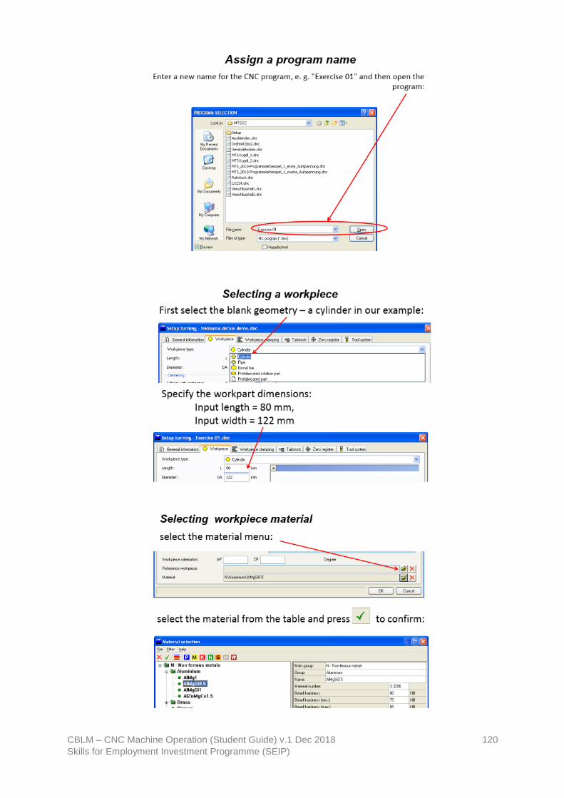
CBLM – CNC Machine Operation (Student Guide) v.1 Dec 2018 120
Skills for Employment Investment Programme (SEIP)

CBLM – CNC Machine Operation (Student Guide) v.1 Dec 2018 121
Skills for Employment Investment Programme (SEIP)

CBLM – CNC Machine Operation (Student Guide) v.1 Dec 2018 122
Skills for Employment Investment Programme (SEIP)

CBLM – CNC Machine Operation (Student Guide) v.1 Dec 2018 123
Skills for Employment Investment Programme (SEIP)

CBLM – CNC Machine Operation (Student Guide) v.1 Dec 2018 124
Skills for Employment Investment Programme (SEIP)