Embed Size (px)
Citation preview

SKF four-row taper roller bearingsSet new performance standards
proof_6109_EN.indd 1 07-04-03 13.56.23

A Productinformation
3 Qualityandchoice3 Why four-row taper roller bearings?3 Why four-row taper roller bearings
from SKF?
4 Uniquedesignfeatures
6 SKFExplorerbearings–aquantumleapforwards
8 Provenbearingarrangements
BRecommendations
10 Applicationadvice10 Design of bearing arrangements11 Lubrication12 Mounting 13 Monitoring the bearings in operation14 Dismounting14 Inspection of SKF Explorer bearings14 Bearing storage
C Productdata
15 Generalbearingdata15 Designs17 Design identification17 SKF Explorer class bearings17 Dimensions17 Tolerances18 Internal clearance18 Influence of operating temperature
on bearing material18 Minimum load18 Equivalent dynamic bearing load18 Equivalent static bearing load18 Comparative load ratings18 Designations and suffixes
20 Producttable
Contents
DAdditionalinformation
34 OtherSKFproducts34 SKF Rubber Outer Diameter Large
Diameter Seals35 SKF Large Diameter Wear Sleeves36 SKF greases38 SKF – the knowledge engineering
company
2
The SKF brand now stands for more than ever before, and means more to you as a valued customer.
While SKF maintains its leadership as the hallmark of quality bearings throughout the world, new dimensions in technical advances, product support and services have evolved SKF into a truly solutions-oriented supplier, creating greater value for customers.
These solutions encompass ways to bring greater productivity to customers, not only with breakthrough application-specific products, but also through leading-edge design simulation tools and consultancy services, plant asset efficiency maintenance programmes,and the industry’s most advanced supply management techniques.
The SKF brand still stands for the very best in rolling bearings, but it now stands for much more.
SKF – the knowledge engineering company
proof_6109_EN.indd 2 07-04-03 13.56.24

Quality and choice
Why four-row taper roller bearings?Four-row taper roller bearings are used successfully worldwide for rolling mill bearing arrangements, particularly as work and back-up roll bearings for hot as well as cold rolling mills. As they can support both heavy radial loads and simultaneously acting axial loads they permit simple and cost effective roll neck bearing arrangements.
Why four-row taper roller bearings from SKF?SKF is long acquainted with the use of rolling bearings in rolling mills. As early as 1922 SKF introduced roller bearings as roll neck bear-ings in the SKF steelworks Hofors Bruk. Since then both builders and operators of rolling mills have benefitted from innovative SKF bearing technology.
SKF four-row taper roller bearings are available in a wide range of sizes and designs appropriate to the application. These include
• TQO and TQI configuration (face-to-face or back-to-back arrangement)
• sealed and open bearings• bearings with or without
extended inner rings• bearings with cylindrical
or tapered bore• bearings with and without
spacer rings.
Specific features of these SKF bearings are, among others
• logarithmic contact profile between rollers and raceways provides a more favourable stress distribution in the bearing and con-siderably enhances operational reliability
• special roller end/flange contact geometry designed to promote lubrication and mini-mise friction and, of course
• quality of SKF manufacture.
However, the technical development of SKF four-row taper roller bearings has been driven yet further. The result – the SKF Explorer four-row taper roller bearings – sets a com-pletely new performance standard.
To appreciate the excellent features and benefits of SKF Explorer bearings, read more about them on the following pages.
A
3
proof_6109_EN.indd 3 07-04-03 13.56.34

Unique design features
SKF taper roller bearings are state-of-the-art products. This was particularly true for the contact conditions in standard bearings, but is even more so for the SKF Explorer bearings.
Favourable stress distributionThe contact geometry between the rollers and raceways has been much improved by the use of logarithmic contact profile geometry resulting in optimized stress distribution in the bearing under all conditions of load and misalignment.
Efficient lubricationThe superior logarithmic contact profile and the optimized raceway surfaces of the rings and rollers not only improve lubrication condi-tions but are also less demanding of the lubricant.
Efficient lubrication of the flangeThe special form of the surfaces of the inner ring guide flanges and the large ends of the rollers considerably enhance lubricant film formation in the sliding roller end/flange contacts.
Even load distribution under normal loads; extended roller/raceway contacts, i.e. lower stresses
Improved stress distri-bution due to reduced edge stresses under heavy loads and also when misaligned, i.e. much higher oper-ational reliability
Improved roller end/flange contact, i.e. optimized lubrication, minimized friction
The C design of the seal leaves space for rollers that are almost as long as those of open bear-ings so that the load carrying capacity is almost equal
Bearings without spacer rings are simpler to mount and the load distribution is better
4
proof_6109_EN.indd 4 07-04-03 13.56.41

Well-designed sealsThe radial shaft seals of SKF four-row taper roller bearings have the form of a C and extend over the cages of the two outboard roller and cage assemblies. Because of the compact design the bearing can incorporate rollers of the same, or almost the same length as the open bearing of the same dimensions so that the load carrying capacity is the same or very similar.
A stainless steel garter spring enables the sealing lip to exert the requisite pressure. The seals are thermally and chemically stable and can operate at high sliding velocities.
O-rings inserted in grooves in the outer ring outside surface prevent dirt and water from penetrating between the outer rings and the chock bore, from where it can contaminate the bearing and cause corrosion.
Spacer rings – if neededEven though most of the bearings in the SKF range of four-row taper roller bearings are now made without spacer rings, bearings with spacer rings are available for applications where they are needed.
Better: without spacer ringsBearings without spacer rings are generally the better engineering solution and have two main advantages:
• They comprise fewer component parts and can thus be mounted more easily and quickly.
• Four separate outer rings contribute to a more even load distribution and conse-quently, a longer service life.
A
5
proof_6109_EN.indd 5 07-04-03 13.56.44

SKF Explorer bearings – a quantum leap forwards
The performance of the previous standard taper roller bearings has confirmed the ben-efits of the improved roller/raceway geometry and the optimized roller end/flange contact. In addition the new SKF Explorer perform-ance class four-row taper roller bearings meet important customer demands and are characterized by
• higher load carrying capacity• longer service life• unique inspection/maintenance
capabilities• improved seals.
Higher load carrying capacityThe steel used for SKF Explorer bearings has high purity and extreme low oxygen content. The reduction in the number of inclusions increases the fatigue strength as well as the wear resistance and enhances the ability to support heavy and shock loads and increases the dynamic load carrying ability.
Longer service lifeIncreased dynamic load carrying capacity implies longer service life and this is reinforced and extended by the benefits derived from
• a further refinement of the contact geometry
• an increase in flange strength• an increase in manufacturing quality.
A new heat treatment process provides an excellent balance between material hardness and toughness. The high surface hardness increases wear resistance, which is particu-larly important under the tough operating conditions in rolling mills, characterized by contamination by scale and water.
The lubrication conditions in the bearings have also been further improved. Modified cage pocket design improves lubrication at the sliding contact between rollers and cages. The special raceway surface contrib-utes to excellent lubricant film formation at the contacts between rollers and raceways.
SKF Explorer bearings are made of extremely clean steel
Modified cage pocket design improves lubrication
The new seal made of environmentally friendly material seals more efficiently against the rotating inner ring
The cage and roller assemblies can be sep-arated from the inner rings – no special tools are required
The maintenance-friendly seals are easy to remove and reinstall
oxygen content
normal bearing steel
steel for SKF Explorer bearings
6
proof_6109_EN.indd 6 07-04-03 13.56.50

Finally, the precise matching between the roller rows makes for a more even load distri-bution over all four rows of rollers.
There is thus a solid foundation for the longer service life of the SKF Explorer bear-ings compared with their predecessors.
Improved sealsThe new seals are made of environmentally friendly hydrogenated acrylonitrile butadiene rubber. The new seal design has resulted in improved retention and sealing in the outer ring and increased sealing efficiency against the inner ring land.
Unique inspection/maintenance capabilitiesUnder the operating conditions which some four-row taper roller bearings are exposed to even the best bearings require efficient maintenance. The newly developed cage allows the cage and roller assemblies to be removed from the inner rings and to be reinstalled. It is now possible to inspect the inner rings com-pletely and if necessary, to refurbish them.
The seals also have been redesigned to be more maintenance-friendly. They are simply snapped into their retaining grooves. Dismounting and reinstallation could not be easier.
Efficient refurbishmentThe SKF Explorer four-row taper roller bear-ings have decisive advantages when it comes to refurbishment:
• The cage and roller assemblies can now be easily dismantled from, and reassembled to the inner rings, allowing full inspection and eventual refurbishment.
• Cage and roller assemblies and inner and outer rings of various bearings can now be combined as desired to form “new” bearings. All that is required is to regrind the ring side faces, which is now also pos-sible for inner rings.
• The new seal design permits quick removal and installation.
AvailabilityThe most popular four-row taper roller bear-ings are already produced to the SKF Explorer performance class specifications. The designa-tions of the SKF Explorer bearings are printed in blue in the product table.
Product identificationThe designation of an SKF Explorer four-row taper roller bearing is the same as that of the previous standard bearing except that it carries the suffix E for easy recognition.
A
�
proof_6109_EN.indd 7 07-04-03 13.56.54

Proven bearing arrangements
SKF four-row taper roller bearings have been successfully used in rolling mills around the world for decades. The bearings are charac-terized by accuracy and reliability even under extreme operating conditions.
Whether in hot or cold rolling mills for flat products or profiles, SKF four-row taper roller bearings are often the first choice.
Over the past 80 years, SKF has accumu-lated considerable experience with rolling bearings in the steel industry and this know-how is always available to customers of the world’s leading rolling bearing manufacturer. SKF application engineers provide support to both machine builders and end users around the world. On request, SKF experts will assist in mounting bearings and training mainten-ance personnel. When needed, SKF specialists are available on site anywhere in the world – saving time and money for the customer.
Applications• heavy plate mills• hot strip mills• cold rolling mills• skin pass mills• roughing mills• universal beam mills• rod, bar and wire mills
Requirements• long service life• precisely defined performance• low maintenance • no unplanned stoppages• environmental friendliness• technical support
Solution
8
proof_6109_EN.indd 8 07-04-03 13.56.59

A
�
proof_6109_EN.indd 9 07-04-03 13.57.06

Application advice
Design of bearing arrangements
Roll neck requirementsIn most rolling mill applications four-row taper roller bearings are mounted with a loose fit on the roll neck. The roll neck journal and the axial abutment for the inner rings must have a certain minimum hardness. The recommended hardness is
• 45 Shore (≈ 34 HRC) for the roll neck surface
• 60 Shore (≈ 45 HRC) for the axial abutments for the inner rings.
0,2 -1,3
Standard application of a grease-lubricated four-row taper roller bearing with axial location of the inner rings
Fig.1
Axial location of inner rings on the roll neckThe inner rings must not be axially clamped. A total axial clearance of 0,4 to 1,3 mm (fig.1) must remain between the inner rings and their abutments.
The SKF four-row taper roller bearings in the advanced design without spacer rings and the Explorer bearings are produced with an extremely limited width tolerance ”B” of +/– 0,25 mm (fig.1).
When following the recommended toler-ances of the customer specific dimensions “A”, “C” and “L” (fig.1), the suitable axial clearance as mentioned is automatically given. Due to this fact, adjustment by a big lock nut becomes no longer necessary. When changing over the application to other designs or in the case
of new developments, there will be no need for a lock anymore (fig.1).
For applications with sealed four-row taper roller bearings, drain slots should be refitted or allowed for. These slots are to be arranged in the 6 o’clock position at the surrounding parts (fig.1), thus ensuring that the possible water intruding from external seals can be drained.
10
proof_6109_EN.indd 10 07-04-03 13.57.07

Lubrication
No bearing arrangement will function prop-erly unless it is adequately lubricated. Depend-ing on the design, several options are avail-able for the lubrication of SKF four-row taper roller bearings.
Bearings without seals may be lubricated with grease (continuously or periodically) or with oil: oil bath, oil bath supplemented with oil-air, oil mist or circulating oil.
Sealed four-row taper roller bearings are manufactured to two designs
• bearings which can be relubricated, the VA901 and VA903 or E1 and E3 executions for grease or oil lubrication
• completely sealed bearings, the VA902 or E2 executions only for grease lubrication.
Completely sealed bearings without lubrication facilityThe bearings without relubrication facility should be filled with a high quality grease on mounting. The SKF grease LGHB 2 (†page36), is recommended. The bearings normally are in operation in the chock for some 1 000 to 1 500 hours, depending
Sealed four-row taper roller bearing lubricated by oil-air
Fig.2
on the working conditions. They are then removed from the chock, dismounted, washed, preserved, inspected and then filled with grease and remounted in the cleaned and inspected chock, the outer rings having been turned to expose a fresh loaded zone.
Oil-air lubrication for sealed bearingsThe sealed bearings with relubrication feature when lubricated by oil-air can contribute to improved operational economy and reliability, particularly in cold rolling mills. The oil-air mixture is introduced from above via the grooves in the side faces of the individual outer rings (†fig.2). Compared with oil mist lubrication, only about one tenth of the lubri-cant quantity is required. The oil can be very accurately metered so that there is no risk of over-lubrication with its attendant heat generation at high rolling speeds.
Oil having a viscosity of up to 700 mm2/s can be used and requires no heating. Metered drops are transported to the bearing along the walls of the ducts and leads by air. The drops are released from the ducts and finally collect at the bottom of the bearing. The air exits via the seals and is clean so that it does not con-
taminate the environment. The air stream then exits via the radial shaft seal, the V-ring and the labyrinth and serves to enhance the sealing efficiency of the labyrinth seal.
The air supplied to the oil-air lubrication equipment should be dried to prevent mois-ture being introduced into the bearing and causing corrosion.
Because the conditions in the chock are relatively clean, the use of the oil-air method can appreciably extend the service life of the bearings.
For applications with oil-air lubrication and when changing over to sealed four-row taper roller bearings, contact the SKF application engineering service.
B
11
proof_6109_EN.indd 11 07-04-03 13.57.09

Mounting
Four-row taper roller bearings are high- precision mechanical components and should therefore be handled with appropriate care when mounting and dismounting. It is impor-tant to use the appropriate aids and tools and to follow the instructions supplied with each bearing. Detailed information is also contained in the SKF publications
• “Mounting and maintenance instructions for four-row taper roller bearings”
• “Four-row taper roller bearings without spacer rings – mounting and maintenance instructions”.
Matching the bearing componentsWhen mounting four-row taper roller bear-ings, the individual components of the bearing must be mounted in the correct order. Parts belonging together are identified by letter markings. All the components of one bearing are also marked with the same serial number, so that the parts of one bearing are not mixed with those of another when several bearings are mounted at the same time (†fig.3). Note: To make sure that the bearing compon-ents are mounted in the correct order, a sheet containing mounting instructions is packed with each bearing. This carefully describes the various steps involved (†fig.4).
Mounting instructions are supplied with every bearing
Fig.4
Loaded zone markingsIn the majority of cases in rolling mills, the outer rings of the bearings are subjected to a point load (constant direction). This means that only a section of the outer ring raceway will be under load. For this reason, the outer rings are divided into four zones which are indicated by the markings I to IV on the side faces of the rings (†fig.5). The markings indicating load zone I are also indicated by a line extending across the whole width of the outer rings. When mounting for the first time it is customary to install the bearing so that the zone I lies in the direction of the load. After each inspection, the outer rings should be turned so that another zone becomes the loaded zone. The order I, III, II, IV is recommended.
Fig.5
Load zone markings on the outer ring
Marking of parts belonging together with serial number and letters
Fig.3
12
proof_6109_EN.indd 12 07-04-03 13.57.14

Monitoring the bearings in operationSKF has considerable experience in the field of condition monitoring. The procedures developed by SKF are based on multi-param-eter measurements. In addition to vibration measurements involving vibration velocity, vibration acceleration enveloping and SEE (Spectral Emitted Energy) other physical measurement categories are also measured for condition monitoring. The SKF system “Smart Chock Unit” has been specially devel-oped for roll neck bearing monitoring.
Roll neck bearing arrangement with the Smart Chock UnitThe SKF system “Smart Chock Unit” enables reliable online monitoring of rolling mill bear-ing arrangements as well as the registration of the forces and temperatures occurring. The system includes intelligent analysis software as well as all the sensors and wiring required for condition monitoring (†fig.6). The SKF Smart Chock Unit can be used to
• measure the axial and radial forces in operation
• record the temperatures and temperature distribution
• continually monitor the condition of the roll neck bearing arrangement.
The following benefits for the rolling mill operator derive from the above:
• By detecting the signs of impeding failure at an early stage, failures can be virtually eliminated, thus unplanned stoppages and costly damage to plant can be avoided.
• Productivity is increased. Fewer unplanned stoppages increase plant uptime.
• The quality of the rolled material can be improved. The system supports process control by providing input data.
Fig.6
The “Smart chock unit”, an SKF solution for roll neck bearing arrangements
B
13
proof_6109_EN.indd 13 07-04-03 13.57.20
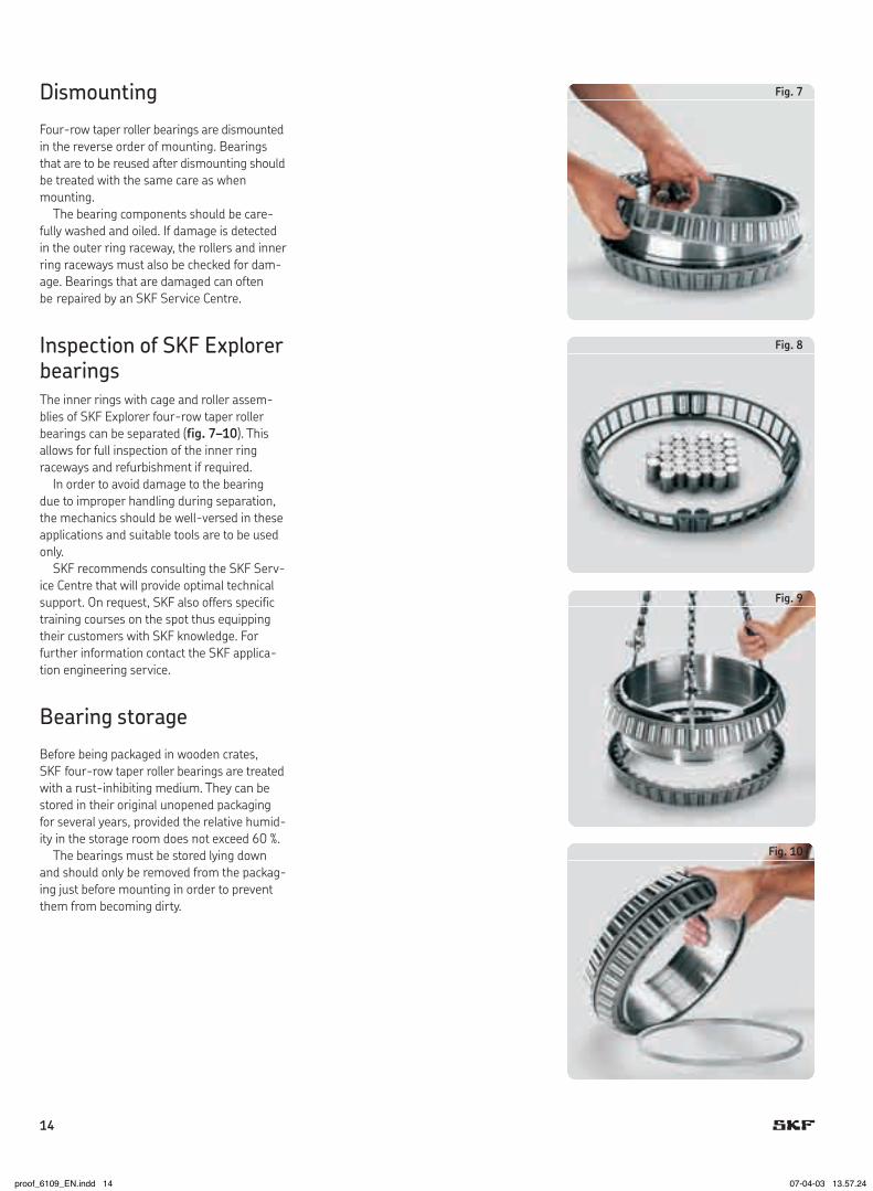
Dismounting
Four-row taper roller bearings are dismounted in the reverse order of mounting. Bearings that are to be reused after dismounting should be treated with the same care as when mounting.
The bearing components should be care-fully washed and oiled. If damage is detected in the outer ring raceway, the rollers and inner ring raceways must also be checked for dam-age. Bearings that are damaged can often be repaired by an SKF Service Centre.
Inspection of SKF Explorer bearings The inner rings with cage and roller assem-blies of SKF Explorer four-row taper roller bearings can be separated (fig.�–10). This allows for full inspection of the inner ring raceways and refurbishment if required.
In order to avoid damage to the bearing due to improper handling during separation, the mechanics should be well-versed in these applications and suitable tools are to be used only.
SKF recommends consulting the SKF Serv-ice Centre that will provide optimal technical support. On request, SKF also offers specific training courses on the spot thus equipping their customers with SKF knowledge. For further information contact the SKF applica-tion engineering service.
Bearing storage
Before being packaged in wooden crates, SKF four-row taper roller bearings are treated with a rust-inhibiting medium. They can be stored in their original unopened packaging for several years, provided the relative humid-ity in the storage room does not exceed 60 %.
The bearings must be stored lying down and should only be removed from the packag-ing just before mounting in order to prevent them from becoming dirty.
Fig.�
Fig.8
Fig.�
Fig.10
14
proof_6109_EN.indd 14 07-04-03 13.57.24

General bearing data
DesignsOpen bearingsSKF four-row taper roller bearings are prima-rily produced with the TQO configuration (†fig.1) in the TQON design without spacer rings (†fig.2) In the TQO configuration, there are two roller and cage assemblies arranged face-to-face. The bearings are nor-mally supplied with pressed steel window-type cages, although the larger sizes may have pierced rollers and steel pin-type cages (†fig.3).
Four-row taper roller bearings are also produced with extended inner rings, which can serve as counterfaces for radial shaft seals (†fig.4). Also these bearings can be supplied without spacer rings (design TQOEN) or with spacer rings (design TQOE).
Four-row taper roller bearings that are to be mounted with a loose fit on the roll neck, are normally supplied with a helical groove in the inner ring bore and lubrication grooves in the side faces of the inner rings. The lubri-cation grooves enable lubricant to be supplied to the contact surfaces of the inner rings and journal seating where there is a risk of wear occurring. Lubricant is stored and wear parti-cles can be deposited in the helical grooves. This reduces wear of the roll neck.
Sealed bearings Sealed SKF four-row taper roller bearings are available in many sizes and designs. When-ever possible, sealed bearings should be used for rolling mills. Compared with open bearings they offer considerable advantages
• they achieve longer service lives• grease consumption is reduced (by up to 90 %)• maintenance intervals can be extended• grease does not escape from the bearings
and the emulsions used for rolling do not become contaminated.
Sealed bearings meet the ecological and eco-nomic requirements now being set. Sealed
bearings can simply replace open bearings as part of a rebuild or refurbishment because the boundary dimensions are the same. Sealed bearings are fitted with specially developed, C-shaped radial shaft seals on both sides. The seals permit high sliding velocities and are intended for operating temperatures between –20 and +140 °C.
The SKF Explorer bearings have sheet steel reinforced radial shaft seals made of hydro-genated acrylonitrile butadiene rubbern (HNBR). They are snapped into the groove in the outer ring.
The other standard bearings have seals made of fluoro rubber (FPM) and reinforced with sheet steel. They are staked in a groove
Fig.1
Fig.2
Fig.3
Fig.4
TQO configurationOpen bearing with spacer rings
TQON designOpen bearing without spacer rings
TQON.1 designOpen bearing without spacer rings with pierced rollers and steel pin-type cage
TQOEN designOpen bearing with extended inner rings. The extensions to the inner rings are designed as concentric sliding surfaces for radial shaft seal
C
15
proof_6109_EN.indd 15 07-04-03 13.57.26

in the outer ring. Fluoro rubber seals require special handling (“Safety precautions”).
O-rings inserted in grooves in the outer ring outside surface prevent dirt or water from entering between the outer rings and the chock bore.
Design E1 and VA901Sealed E1 and VA901 design bearings (†fig.5) can be relubricated via lubrication grooves in the outer rings. In bearings without spacer rings, the seal between the two inner rings consists of a steel reinforced ring of acrylonitrile butadiene rubber. In bearings with spacer rings, the sealing between the inner rings is performed by two O-rings as shown in fig.8. The permissible operating temperature range for these seals is –40 to +100 °C.
Design E2 and VA902Sealed E2 and VA902 design bearings (†fig.6) correspond to the E1 and VA901 designs, but cannot be relubricated.
Design E3 and VA903Sealed E3 and VA903 design bearings (†fig.�) have no seal between the inner rings. All other features are same as for E1 and VA091 design bearings.
Fig.5
Fig.6
Fig.�
Designs E1 and VA901Sealed bearing without spacer rings, with lubri-cation grooves in the outer ring faces
Designs E2 and VA902Sealed bearing without spacer rings, no relubri-cation facilities
Designs E3 and VA903Sealed bearing, with lubrication grooves in the outer ring faces but without seal between the inner rings
Warning: Safety precautions for fluoro rubber!Fluoro rubber is very stable and harmless in normal operating conditions up to +200 °C. However, if exposed to extreme temperatures above 300 °C, e.g. fire or the flame of a cut-ting torch, fluoro rubber seals give off hazardous fumes. These fumes can be harmful if inhaled, as well as to the eyes. In addition, once the seals have been heated to such tem-peratures, they are dangerous to handle even after they have cooled and should not touch the skin. If it is necessary to handle bearings with seals that have been subjected to high temperatures, such as when dismounting the bearing, the following safety precautions should be observed
• always wear protective goggles, gloves and appropriate breathing apparatus• place the remains of the seals in an airtight plastic container marked with
a symbol for “material will etch”• follow the safety precautions in the appropriate material safety data sheet (MSDS).
If there is unintentional contact with the seals, wash hands with soap and plenty of water and flush eyes with plenty of water and consult a doctor immediately. If the fumes have been inhaled, consult a doctor immediately.
The user is responsible for the correct use of the product during its service life and its proper disposal. SKF takes no responsibility for the improper handling of fluoro rubber seals or for any injury resulting from their use.
16
proof_6109_EN.indd 16 07-04-03 13.57.27

Other bearing design variantsIn addition to the bearings shown in the prod-uct table starting on page22, SKF also sup-plies four-row taper roller bearings in another configuration and many other design variants.
This includes, for example, bearings with inner and outer intermediate (spacer) rings between the roller rows Nos. 2 and 3 (†fig.8).
Bearings with the taper roller and cage assembly pairs in a back-to-back arrangement are also produced (TQI configuration). These bearings have one double row and two single row inner rings and two double row outer rings (†fig.�). This arrangement of the roller rows provides relatively stiff bearing arrange-ments which can take up high tilting moments.
For certain applications SKF also supplies bearings with a tapered bore. These are required when the bearing is to be mounted with a tight fit on the journal, for example, when high rolling speeds are to be employed.
Details of these other bearings will be found in the SKF catalogue “Large bearings” and the “SKF Interactive Engineering Cata-logue” online at www.skf.com.
Design identification
To enable the easy identification of the various different designs and variants, letters or letter combinations are given under the heading “Design” in the product table e.g. TQON/GW. The first part of the identification corresponds to the configurations and designs described on pages15 to 1� and shown in figs.1 to �. The letters following the oblique stroke identify variants (†fig.10) and are explained below.
G helical groove in the bearing boreGW G + WGWI G + WIGWSI G + W + SIGWISI G + WI + SIGWOY G + WO + YLS lubrication holes in the inner ring
extensionsW lubrication grooves in the side faces
of both outer and inner rings (WI + WO)WI lubrication grooves in the inner ring
side facesWILS WI + LSWO lubrication grooves in the outer ring
side facesSI seal between the two inner ringsY annular groove and lubrication holes
in the inner rings and gap between the inner rings
.1 pierced rollers and steel pin-type cage
Fig.8
Fig.�
SI
WI
G
Fig.10
TQOSNP designSealed bearing without spacer rings, but with a spacer sleeve between the pairs of roller and cage assemblies
TQI designOpen bearing, pairs of roller and cage assem-blies arranged back- to-back
Design variant identification
SKF Explorer class bearingsSKF Explorer four-row taper roller bearings are available as open bearings without spacer rings or as sealed bearings. The helical groove in the bore and case hardened bearing rings are standard for SKF Explorer bearings and are thus not identified by suffixes in the designation.
Dimensions
The boundary dimensions of four-row taper roller bearings have not been standardized by ISO. The dimensions of many of the cones and cups of the inch-size bearings do, how-ever, conform to the ABMA Standard 19-1974 or ANSI B3.19-1975. The bore and outside diameters, however, often approxi-mate to those of ISO 15:1998 Diameter Series 9 or 0.
Tolerances
SKF four-row taper roller bearings are pro-duced with dimensional accuracy correspond-ing to the Normal tolerance classes for metric and inch-size bearings, respectively.
The running accuracy of all bearings is to tolerance class P5 specifications for metric taper roller bearings.
The width tolerance of the inner rings is
• ± 0,25 mm for bearings without spacer rings and for SKF Explorer bearings
• ± 1,524 mm for bearings with spacer rings.
Exceptions to this are indicated in the product table by footnotes.
The tolerances of the metric bearings con-form to ISO 492:2002 and those of the inch-size bearings follow class 4, ISO 578:1987 and ABMA Standard 19.2-1994.
C
1�
proof_6109_EN.indd 17 07-04-03 13.57.29

Internal clearance
SKF four-row taper roller bearings are deliv-ered as ready-to-mount bearing units with an axial internal clearance adapted to the actual application. For the SKF Explorer bearings the mean value of the axial internal clearance expressed in µm is shown in the designation, preceded by the suffix C, e.g. C300 for a mean clearance of 300 µm (from 270 to 330 µm).
Influence of operating temperatures on bearing material
SKF four-row taper roller bearings are sub-jected to a special heat treatment such that they can be operated at temperatures of up to +150 °C without any inadmissible dimen-sional changes occurring.
Minimum load
In order to guarantee the satisfactory per-formance the bearings must always be sub-jected to a given minimum load. Otherwise the inertia forces of the rollers and cages and the friction in the lubricant can have a detri-mental influence on rolling conditions in the bearing and may cause sliding movements to occur between the rollers and raceways.
The requisite minimum load to be applied can be obtained from
Frm = 0,02 C
whereFrm = minimum radial load, kNC = basic dynamic load rating, kN
The weight of the components supported by the bearing, together with the external rolling forces, almost always exceed the requisite minimum load. If this is not the case an addi-tional radial load must be applied.
Equivalent dynamic bearing loadFor dynamically loaded four-row taper roller bearings
P = Fr + Y1 Fa bei Fa/Fr ≤ eP = 0,67 Fr + Y2 Fa bei Fa/Fr > e
The values for the calculation factors e, Y1 and Y2 will be found in the product table.
Equivalent static bearing loadFor statically loaded four-row taper roller bearings
P0 = Fr + Y0 Fa
Values for the calculation factor Y0 will be found in the product table.
Comparative load ratings
For rolling mill applications, load ratings are often used which are not calculated according to ISO 281:2007 but by a different method based on a rating life of 90 million revolutions (500 r/min for 3 000 operating hours). As a direct comparison of these load ratings with ISO load ratings is not possible, even if they are converted for 1 million revolutions (ISO life definition) “comparative” load ratings cal-culated by the same non-ISO method are given in the product table. These comparative load ratings cannot be used to calculate ISO lives.
For further information please refer to the SKF catalogue “Large bearings” or the “SKF Interactive Engineering Catalogue” online at www.skf.com.
Designations and suffixes
SKF four-row taper roller bearings are gener-ally special bearings and are usually identified by a drawing number. The numbering system has undergone some changes over the years(† designation scheme next page). Bearings having a modified internal design compared with the original are identified by a suffix let-ter A, B or C or a combination of these letters, e.g. AB. The meaning of these suffixes is spe-cific to the drawing number.
Bearings to the SKF Explorer class specifi-cations are identified by the suffix E and have inner and outer rings of case hardened steel as standard. The helical groove in the bore is also standard. Therefore, the relevant suf-fixes (HA1 and G) are not used for these bearings.
18
proof_6109_EN.indd 18 07-04-03 13.57.30

Prefixes
BT4 four-row taper roller bearing (current prefix)BT4B four-row taper roller bearing (earlier prefix)– the bearing type is only defined by the drawing (old SKF system for special bearings)
DrawingNo.
0(000) special bearing with outside diameter < 420 mm8(000) special bearing with outside diameter ≥ 420 mm328000to334��� special taper roller bearing
Design
– original (standard) designA,B,C or combinations of these letters: modified internal design E SKF Explorer bearing without spacer ringsEX SKF Explorer bearing with spacer ringsE(X)1 SKF Explorer bearings with seals of hydrogenated acrylonitrile butadiene rubber (HNBR), otherwise to VA901 specificationE(X)2 SKF Explorer bearings with seals of hydrogenated acrylonitrile butadiene rubber (HNBR), otherwise to VA902 specificationE(X)3 SKF Explorer bearings with seals of hydrogenated acrylonitrile butadiene rubber (HNBR), otherwise to VA903 specificationG helical groove in bearing bore
Material
– standardHA1 outer and inner rings of case hardened steelHA4 outer and inner rings and rollers of case hardened steelHE1 outer and inner rings of vacuum remelted steel
Internalclearance
– standardC300 axial internal clearance, mean value 300 µmC400 axial internal clearance, mean value 400 µm etc.
Sealdesign
VA�01 fluoro rubber (FPM) seals at both sides, sealing ring between inner rings, can be relubricated via outer ringVA�02 fluoro rubber (FPM) seals at both sides, sealing ring between inner rings, cannot be relubricatedVA�03 as VA901 but without sealing ring between inner ringsVA�1� Sealed design bearing without seals, recesses for seals and O-rings availableVA�1� fluoro rubber (FPM) seals at both sides, can be relubricated via outer ring, inner rings without lubrication grooves in side faces, but with annular groove in bore and lubrication holes through guide flangeVA�41 fluoro rubber (FPM) seals at both sides, cannot be relubricated via outer ring, inner ring with lubrication grooves in inboard side faces and annular groove and lubrication holes at outboard side between inner rings
BT4B
BT4
334106
808�
3308�0
HA1
C300
C300 VA�01
–
–
/
/
EX1
BG
BG
C
1�
proof_6109_EN.indd 19 07-04-03 13.57.31

13�,�00 200,025 160,338 157,162 158 178 0,8 3,3 15,5 331138AG TQO/GWI5,5000 7,8750 6,3125 6,1875 1��,800 247,650 192,088 192,088 193 216 1,5 3,3 29 331480 TQO/WI7,0000 9,7500 7,5625 7,5625 247,650 192,088 192,088 192 209 1 3,3 27 BT4-0010/HA1C400VA�03 TQOS/GWI 9,7500 7,5625 7,5625 1�8,438 284,162 225,425 225,425 217 250 3,3 3,3 45,4 BT4-002�/HA1 TQON/W7,8125 11,1875 8,8750 8,8750 205,000 320,000 203,500 203,5 233 280 4 3 54,5 BT4B328065/HA1 TQO/WI8,0709 12,5984 8,0118 8,0118 206,3�5 282,575 190,500 190,5 223 247 0,8 3,3 36,5 331486G TQO/GWI8,1250 11,1250 7,5000 7,5000 282,575 190,500 190,5 222 240 0,6 3,3 32 BT4-0013G/HA1C400VA�03 TQOS/GWI 11,1250 7,5000 7,5000 282,575 190,500 190,5 223 247 0,8 3,3 35,8 BT4-0021G/HA1 TQON/GW 11,1250 7,5000 7,5000 216,103 330,200 269,875 263,525 238 274 1,5 3,3 84 BT4B328204/HA1 TQO/W8,5080 13,0000 10,6250 10,3750 220,662 314,325 239,712 239,712 242 278 1,5 3,3 61,5 331156G TQO/GWI8,6875 12,3750 9,4375 9,4375 240,000 338,000 248,000 248 258 298 4 3 69,3 BT4-0020/HA1 TQON/W9,4488 13,3071 9,7638 9,7638 241,503 349,193 228,600 228,6 271 308 1,5 3,3 74,5 330�82AG TQO/GWI9,5080 13,7478 9,0000 9,0000 244,4�5 327,025 193,675 193,675 264 299 1,5 3,3 46 330862B TQO/WI9,6250 12,8750 7,6250 7,6250 254,000 358,775 269,875 269,875 272 320 1,5 3,3 84 BT4B32�0�1G/HA1VA�01 TQOS/GWISI10,0000 14,1250 10,6250 10,6250 358,775 269,875 269,875 279 319 1,5 3,3 88 3312�5B TQO/WI 14,1250 10,6250 10,6250 266,�00 355,600 228,600 230,188 285 315 1 3,3 60,5 BT4-0014G/HA1C400VA�03 TQOS/GWI10,5000 14,0000 9,0000 9,0625 355,600 228,600 230,188 288 322 1,5 3,3 65,5 BT4B32820�G/HA1C455 TQO/WI 14,0000 9,0000 9,0625 26�,8�5 381,000 282,575 282,575 296 339 3,3 3,3 105 BT4B331168B TQO/WI10,6250 15,0000 11,1250 11,1250
Dimensions Mass Designation Design
d D T B d1 D1 r1,2 r3,4 ≈ ≈ min min
mm/in kg – –
Four-rowtaperrollerbearingsd 13�,�00–26�,8�5 mm
D1 d d1
r1
r4 r3
T
r2
D
B
TQOSN/GWSITQON/GW
20
proof_6109_EN.indd 20 07-04-03 13.57.33

TQOSN/WILSTQON/W
331138AG 858 2 080 208 0,33 2 3 2 250 41,4 1,91 331480 1 230 3 000 285 0,44 1,5 2,3 1,4 360 78,2 1,33 BT4-0010/HA1C400VA�03 1 020 2 500 232 0,4 1,7 2,5 1,6 290 59,4 1,43 BT4-002�/HA1 1 680 3 550 335 0,4 1,7 2,5 1,6 415 81,1 1,48 BT4B328065/HA1 1 900 3 650 345 0,46 1,5 2,2 1,4 500 113 1,29 331486G 1 300 3 350 305 0,5 1,35 2 1,3 340 85,2 1,15 BT4-0013G/HA1C400VA�03 1 140 2 500 240 0,5 1,35 2 1,3 300 72,7 1,19 BT4-0021G/HA1 1 300 3 350 305 0,5 1,35 2 1,3 340 85,2 1,15 BT4B328204/HA1 2 240 5 100 475 0,54 1,25 1,8 1,3 600 160 1,06 331156G 2 200 5 200 465 0,33 2 3 2 585 94,3 1,76 BT4-0020/HA1 2 550 5 500 490 0,4 1,7 2,5 1,6 620 119 1,51 330�82AG 2 160 5 000 455 0,35 1,9 2,9 1,8 570 98,8 1,65 330862B 1 830 4 300 390 0,33 2 3 2 475 75,3 1,82 BT4B32�0�1G/HA1VA�01 2 330 5 400 480 0,33 2 3 2 620 102 1,76 3312�5B 2 860 7 100 620 0,33 2 3 2 765 125 1,76 BT4-0014G/HA1C400VA�03 1 870 4 650 415 0,35 1,9 2,9 1,8 490 85,6 1,67 BT4B32820�G/HA1C455 2 200 5 600 500 0,35 1,9 2,9 1,8 585 102 1,62 BT4B331168B 3 080 7 500 655 0,33 2 3 2 815 132 1,76
Designation Basicloadratings Fatigue Calculationfactors Comparativedata dyn. stat. loadlimit Load ratings Thrust radial axial factor C C0 Pu e Y1 Y2 Y0 CF CFa K
– kN kN – kN –
CC
21
proof_6109_EN.indd 21 07-04-03 13.57.35

Four-rowtaperrollerbearingsd 2�6,225–343,052 mm
D1 d d1
r1
r4 r3
T
r2
D
B
TQOSN/GWSITQON/GW
2�6,225 393,700 269,875 269,875 302 358 1 6,4 98,5 BT4-0012G/HA1C500VA�01 TQOS/GWISI10,8750 15,5000 10,6250 10,6250 2��,400 393,700 269,875 269,875 302 347 1 6,4 95,5 BT4-0011G/HA1C500VA�01 TQOS/GWISI11,0000 15,5000 10,6250 10,6250 2��,503 380,943 244,475 244,475 308 337 1,5 3,3 86 330540AG TQO/WI11,0041 14,9978 9,6250 9,6250 285,�50 380,898 244,475 244,475 308 337 1,5 3,3 81 33033�AG TQO/WI11,2500 14,9960 9,6250 9,6250 380,898 244,475 244,475 301 346 1 3,3 74 BT4-0015G/HA1C400VA�03 TQOS/GW 14,9960 9,6250 9,6250 288,�50 406,451 298,450 298,45 314 361 3,3 3,3 125 BT4B331452G/HA1 TQO/WI11,3760 16,0020 11,7500 11,7500 304,�02 412,648 266,700 266,7 328 378 1 3,3 99 BT4-0016G/HA1C200VA�01 TQOS/GWISI12,0040 16,2460 10,5000 10,5000 412,648 266,700 266,7 328 374 3,3 3,3 102,5 330�58BG TQO/GWI 16,2460 10,5000 10,5000 412,648 266,700 266,7 325 374 3,3 3,3 100 BT4-0004G/HA1 TQON/GW 16,2460 10,5000 10,5000
31�,500 422,275 269,875 269,875 342 384 1,5 3,3 105 3308�0BG TQON/GW12,500 16,625 10,625 10,625 422,275 269,875 269,875 338 389 1,5 3,3 94,5 *BT4B334023E1/C6�5 TQOSN/GWSI 16,625 10,625 10,625 447,675 327,025 327,025 340 398 3,3 3,3 165 BT4B331161BG/HA1 TQON/GW 17,625 12,875 12,875 330,302 438,023 254 247,65 345 405 1 3,3 105 *BT4-8113E2/C500 TQOSN/GWSI13,004 17,245 10 9,75
333,3�5 469,9 342,9 342,9 362 420 3,3 3,3 185 BT4-801�/HA1C600VA�41 TQOSN/WILS13,125 18,5 13,5 13,5
340,000 520 323,5 323,5 378 490 6 6 240 BT4B332�63B/HA1 TQON/W13,386 20,4724 12,7362 12,7362
342,�00 533,4 301,625 307,975 390 475 3,3 3,3 240 BT4-8034G/HA1 TQON/GW13,500 21 11,875 12,125
343,052 457,098 254 254 366 413 1,5 3,3 110 *330661E/C4�5 TQON/GW13,506 17,996 10 10 457,098 254 254 362 420 1 3,3 110 *BT4B32881�E1/C4�5 TQOSN/GWSI 17,996 10 10 457,098 254 254 362 420 1 3,3 105 BT4B334106BG/HA1C300VA�01 TQOSN/GWSI 17,996 10 10
Dimensions Mass Designation Design
d D T B d1 D1 r1,2 r3,4 ≈ ≈ min min
mm/in kg – –
* SKF Explorer bearing. Other bearings will be converted to the Explorer class continuously. Please ask for availability of further SKF Explorer bearings
22
proof_6109_EN.indd 22 07-04-03 13.57.37

TQOEN/GWTQOSN/GW
BT4-0012G/HA1C500VA�01 2 750 5 850 530 0,37 1,8 2,7 1,8 720 134 1,55 BT4-0011G/HA1C500VA�01 2 750 5 850 530 0,37 1,8 2,7 1,8 720 134 1,55 330540AG 2 290 6 400 540 0,43 1,6 2,3 1,6 600 128 1,35 33033�AG 2 290 6 400 540 0,43 1,6 2,3 1,6 600 128 1,35 BT4-0015G/HA1C400VA�03 2 200 5 500 480 0,43 1,6 2,3 1,6 585 120 1,38 BT4B331452G/HA1 3 580 9 000 765 0,33 2 3 2 950 159 1,73 BT4-0016G/HA1C200VA�01 2 700 6 700 585 0,31 2,2 3,3 2,2 710 110 1,85 330�58BG 2 970 7 500 640 0,31 2,2 3,3 2,2 780 122 1,83 BT4-0004G/HA1 3 190 7 500 640 0,31 2,2 3,3 2,2 780 122 1,83
3308�0BG 3 360 8 150 680 0,31 2,2 3,3 2,2 815 129 1,83 BT4B334023E1/C6�5 3 250 6 550 570 0,33 2 3 2 695 114 1,76 BT4B331161BG/HA1 4 730 10 800 880 0,33 2 3 2 1 160 193 1,74
BT4-8113E2/C500 3 400 6 400 550 0,45 1,5 2,2 1,45 720 158 1,29
BT4-801�/HA1C600VA�41 4 130 10 200 830 0,33 2 3 2 1 000 165 1,76
BT4B332�63B/HA1 5 610 10 400 880 0,3 2,3 3,4 2,2 1 370 194 2,01
BT4-8034G/HA1 4 730 8 800 720 0,33 2 3 2 1 160 190 1,76
330661E/C4�5 3 450 6 800 570 0,48 1,4 2,1 1,4 735 171 1,24 BT4B32881�E1/C4�5 3 350 6 400 540 0,48 1,4 2,1 1,4 710 166 1,23 BT4B334106BG/HA1C300VA�01 2 550 6 000 510 0,68 1 1,5 1 610 210 0,84
Designation Basicloadratings Fatigue Calculationfactors Comparativedata dyn. stat. loadlimit Load ratings Thrust radial axial factor C C0 Pu e Y1 Y2 Y0 CF CFa K
– kN kN – kN –
CC
23
proof_6109_EN.indd 23 07-04-03 13.57.39

Four-rowtaperrollerbearingsd 3�4,662–3�5,000 mm
D1 d d1
r1
r4 r3
T
r2
D
B
TQON.1/GWTQON/GW
34�,662 469,9 260,35 260,35 372 430 1,5 3,3 125 BT4B3310��BG/HA1 TQON/GW13,687 18,5 10,25 10,25
350,000 480 420 420 376 436 1 4 211 *BT4-811�E1/C4�5 TQOSN/GWSI13,780 18,8976 16,5354 16,5354
355,000 490 316 316 382 446 1,5 3,3 170 BT4-8020G/HA1VA�01 TQOSN/GWSI13,976 19,2913 12,4409 12,4409
355,600 482,6 269,875 265,113 382 432 1,5 3,3 140 *330662E/C480 TQON/GW14,000 19 10,625 10,4375 482,6 269,875 265,113 380 436 1,5 3,3 134 *BT4B3288�0EX1/C480 TQOS/GWSI 19 10,625 10,4375 488,95 317,5 317,5 392 448 1,5 3,3 180 3312�1BG TQON/GW 19,25 12,5 12,5 488,95 317,5 317,5 382 446 1 3,3 170 *BT4B328�12E3/C6�5 TQOSN/GW 19,25 12,5 12,5 488,95 317,5 317,5 382 446 1 3,3 170 *BT4B328�12E1/C300 TQOSN/GWSI 19,25 12,5 12,5
360,000 540 325 325 398 485 1,5 3 250 BT4-8015G/HA1 TQON/GW14,173 21,2598 12,7953 12,7953
380,000 560 360 390 417 500 3,3 5 300 BT4-8033G/HA1 TQOEN/GW14,961 22,0472 14,1732 15,3543
384,1�5 546,1 400,05 400,05 416 496 3,3 6,4 300 BT4-8025G/HA1C300VA�03 TQOSN/GW15,125 21,5 15,75 15,75 546,1 400,05 400,05 419 484 3,3 6,4 311 *33114�E/C6�5 TQON/GW 21,5 15,75 15,75
385,�62 514,35 317,5 317,5 411 471 1 3,3 175 *BT4B334042E1/C5�5 TQOSN/GWSI15,188 20,25 12,5 12,5
3�5,000 545 288,9 268 435 498 5 10 192 *BT4B332824E/C4�5 TQON/GW15,551 21,4567 11,374 10,551
Dimensions Mass Designation Design
d D T B d1 D1 r1,2 r3,4 ≈ ≈ min min
mm/in kg – –
1) Non-standard inner ring width tolerance* SKF Explorer bearing. Other bearings will be converted to the Explorer class continuously. Please ask for availability of further SKF Explorer bearings
24
proof_6109_EN.indd 24 07-04-03 13.57.41

TQOSN/GWISITQOSN/GWSI
BT4B3310��BG/HA1 3 910 8 500 695 0,33 2 3 2 950 153 1,76
BT4-811�E1/C4�5 4 750 10 200 815 0,46 1 2,2 1,45 1 020 227 1,28
BT4-8020G/HA1VA�01 4 460 10 000 830 0,33 2 3 2 1 080 177 1,75
330662E/C480 4 000 8 000 655 0,48 1,4 2,1 1,4 850 198 1,24 BT4B3288�0EX1/C480 3 550 7 500 630 0,46 1,5 2,2 1,4 815 187 1,24 3312�1BG 4 460 11 000 880 0,33 2 3 2 1 080 179 1,76 BT4B328�12E3/C6�5 5 100 10 000 830 0,33 2 3 2 1 080 177 1,75 BT4B328�12E1/C300 5 100 10 000 830 0,33 2 3 2 1 080 177 1,75
BT4-8015G/HA1 5 720 10 800 900 0,3 2,3 3,4 2,2 1 400 207 1,93
BT4-8033G/HA1 6 710 13 700 1 080 0,4 1,7 2,5 1,6 1 630 330 1,4
BT4-8025G/HA1C300VA�03 6 160 15 000 1 180 0,35 1,9 2,9 1,8 1 500 256 1,68 33114�E/C6�5 8 000 16 600 1 290 0,33 2 3 2 1 730 278 1,24
BT4B334042E1/C5�5 4 800 10 000 780 0,4 1,7 2,5 1,6 1 020 195 1,49
BT4B332824E/C4�5 4 800 9 500 750 0,48 1,4 2,1 1,4 1 020 238 1,22
Designation Basicloadratings Fatigue Calculationfactors Comparativedata dyn. stat. loadlimit Load ratings Thrust radial axial factor C C0 Pu e Y1 Y2 Y0 CF CFa K
– kN kN – kN –
CC
25
proof_6109_EN.indd 25 07-04-03 13.57.43

Four-rowtaperrollerbearingsd 406,400–44�,600 mm
D1 d d1
r1
r4 r3
T
r2
D
B
TQOSN/GWSITQON/GW
406,400 546,1 288,925 288,925 434 494 1,5 6,4 186 *BT4B330650E/C500 TQON/GW16,000 21,5 11,375 11,375 546,1 288,925 288,925 434 494 1,5 6,4 186 *BT4B330650EX/C500 TQO/GW 21,5 11,375 11,375 546,1 288,925 288,925 434 498 1,5 6,4 180 BT4B328838BG/HA1VA�01 TQOSN/GWSI 21,5 11,375 11,375 546,1 288,925 288,925 434 498 1,5 6,4 180 BT4B328838BG/HA1VA�02 TQOSN/GWISI 21,5 11,375 11,375 546,1 288,925 288,925 434 498 1,5 6,4 185 BT4-8014G/HA1VA�01 TQOSN/GWSI 21,5 11,375 11,375 546,1 288,925 268,288 434 494 1,5 6,4 180 331465BG TQON/GW 21,5 11,375 10,5625 546,1 330 330 434 498 1,5 6,4 200 BT4B3340�3BG/HA1VA�02 TQOSN/GWISI 21,5 12,9921 12,9992 546,1 330 330 438 498 1,5 6,4 225 BT4B3340�2AG/HA1 TQON/GW 21,5 12,9921 12,9992 565,15 440 440 436 508 1,5 6,4 340 BT4-8002G/HA1 TQON/GW 22,25 17,3228 17,3228
40�,5�5 546,1 334,962 334,962 434 498 1 6,4 205 BT4-8021G/HA1VA�1� TQOSN/GWOY16,125 21,5 13,1875 13,1875 546,1 334,962 334,962 434 498 1 6,4 205 *BT4B32�004E1/C5�5 TQOSN/GWSI 21,5 13,1875 13,1875 546,1 334,962 334,962 438 490 1,5 6,4 220 *BT4B331333E/C5�5 TQON/GW 21,5 13,1875 13,1875
420,000 574 480 480 450 530 2,5 5 345 BT4-8018G/HA1VA�011) TQOSN/GWSI16,535 22,5984 18,8976 18,8976
430,000 570 380 380 458 510 2 5 260 BT4-804�G/HA1 TQON/GW16,929 22,4409 14,9606 14,9606 575 380 380 458 518 1,5 5 280 BT4-8006BG/HA1 TQON/GW 22,6378 14,9606 14,9606 640 465 465 486 578 2,5 4 530 BT4-8040G/HA4 TQON.1/GW 25,1969 18,3071 18,3071
431,800 571,5 279,4 279,4 458 530 1,5 3,3 185 BT4-801�G/HA1VA�01 TQOSN/GWSI17,000 22,5 11 11 571,5 336,55 336,55 458 516 1,5 3,3 240 BT4B331226BG/HA1 TQON/GW 22,5 13,25 13,25 571,5 336,55 336,55 458 530 1,5 3,3 215 *BT4-8003E2/C550 TQOSN/GWISI 22,5 13,25 13,25
440,000 590 480 480 468 539 1 5 365 BT4B334055ABG/HA1VA�021) TQOSN/GWISI17,323 23,2283 18,8976 18,8976
44�,600 635 463,5 463,5 488 588 3,3 6,4 470 BT4-803�G/HA1VA�01 TQOSN/GWSI17,622 25 18,248 18,248
Dimensions Mass Designation Design
d D T B d1 D1 r1,2 r3,4 ≈ ≈ min min
mm/in kg – –
1) Non-standard inner ring width tolerance* SKF Explorer bearing. Other bearings will be converted to the Explorer class continuously. Please ask for availability of further SKF Explorer bearings
26
proof_6109_EN.indd 26 07-04-03 13.57.45

TQOESN/GWSITQOEN/GW
BT4B330650E/C500 5 000 10 200 815 0,48 1,4 2,1 1,4 1 080 252 1,23 BT4B330650EX/C500 4 650 10 200 815 0,48 1,4 2,1 1,4 1 080 252 1,23 BT4B328838BG/HA1VA�01 4 180 9 500 750 0,48 1,4 2,1 1,4 1 020 238 1,22 BT4B328838BG/HA1VA�02 4 180 9 500 750 0,48 1,4 2,1 1,4 1 020 238 1,22 BT4-8014G/HA1VA�01 3 300 7 800 655 0,68 1 1,5 1 800 276 0,84 331465BG 4 180 9 500 750 0,48 1,4 2,1 1,4 1 020 238 1,22 BT4B3340�3BG/HA1VA�02 4 400 10 200 815 0,48 1,4 2,1 1,4 1 080 252 1,23 BT4B3340�2AG/HA1 5 010 13 200 1 000 0,43 1,6 2,3 1,6 1 220 254 1,4 BT4-8002G/HA1 7 650 18 600 1 430 0,33 2 3 2 1 900 302 1,82
BT4-8021G/HA1VA�1� 4 840 12 000 950 0,4 1,7 2,5 1,6 1 200 231 1,47 BT4B32�004E1/C5�5 5 600 12 000 950 0,4 1,7 2,5 1,6 1 200 231 1,47 BT4B331333E/C5�5 5 700 13 200 1 000 0,43 1,6 2,3 1,6 1 220 254 1,4
BT4-8018G/HA1VA�011) 7 210 18 600 1 430 0,31 2,2 3,3 2,2 1 760 279 1,83
BT4-804�G/HA1 5 280 14 000 1 060 0,44 1,5 2,3 1,4 1 290 282 1,33 BT4-8006BG/HA1 6 440 16 600 1 250 0,4 1,7 2,5 1,6 1 560 315 1,43 BT4-8040G/HA4 9 520 21 200 1 560 0,26 2,6 3,9 2,5 2 360 308 2,21
BT4-801�G/HA1VA�01 3 740 9 000 735 0,54 1,25 1,8 1,3 915 243 1,07 BT4B331226BG/HA1 5 280 14 000 1 060 0,44 1,5 2,3 1,4 1 290 282 1,33 BT4-8003E2/C550 5 600 12 700 980 0,44 1,5 2,3 1,4 1 180 254 1,34
BT4B334055ABG/HA1VA�021) 7 650 20 000 1 460 0,28 2,4 3,6 2,5 1 860 255 2,12
BT4-803�G/HA1VA�01 7 650 20 000 1 460 0,33 2 3 2 1 900 313 1,76
Designation Basicloadratings Fatigue Calculationfactors Comparativedata dyn. stat. loadlimit Load ratings Thrust radial axial factor C C0 Pu e Y1 Y2 Y0 CF CFa K
– kN kN – kN –
CC
2�
proof_6109_EN.indd 27 07-04-03 13.57.47

Four-rowtaperrollerbearingsd 450,000–482,600 mm
D1 d d1
r1
r4 r3
T
r2
D
B
TQOSN/GWSITQON/GW
450,000 595 368 368 484 550 3 6 265 BT4-8023G/HA1VA�1� TQOSN/GWOY17,717 23,4252 14,4882 14,4882 595 368 368 486 542 3 6 285 *BT4B332��3E/C�25 TQON/GW 23,4252 14,4882 14,4882 595 404 404 480 545 2 6 305 BT4-8044G/HA1VA�021) TQOSN/GWISI 23,4252 15,9055 15,9055 595 415 415 478 544 1,5 6 320 BT4-8024G/HA1 TQON/GW 23,4252 16,3386 16,3386
45�,200 596,9 279,4 276,225 484 550 1,5 3,3 190 BT4B32882�ABG/HA1VA�02 TQOSN/GWISI18,000 23,5 11 10,875 596,9 279,4 276,225 484 550 1,5 3,3 190 *BT4B32882�E2/C500 TQOSN/GWISI 23,5 11 10,875 596,9 279,4 276,225 487 544 1,5 3,3 197 *33116�E/C500 TQON/GW 23,5 11 10,875
460,000 610 360 360 488 562 1,5 6 279 *BT4-8111E2/C�25 TQOSN/GWISI18,110 24,0157 14,1732 14,1732 610 360 360 479 565 3 6 290 *BT4B331���E/C�25 TQON/GW 24,0157 14,1732 14,1732 615,95 330,2 330,2 505 577 1 6,4 233 *BT4B328842E1/C�25 TQOSN/GWSI 24,25 13 13
4�5,000 600 368 368 500 554 2 6 250 BT4B328�13BG/HA1C555 TQON/GW18,701 23,622 14,4882 14,4882 640 360 360 512 568 2 6 335 BT4-8035G/HA1 TQON/GW 25,1968 14,1732 14,1732
4��,425 679,45 495,3 495,3 520 610 3,3 6,4 585 BT4B330886CG/HA1 TQON/GW18,875 26,75 19,5 19,5 679,45 495,3 495,3 520 610 3,3 6,4 565 BT4B334116BG/HA1VA�01 TQOSN/GWSI 26,75 19,5 19,5
482,600 615,95 330,2 330,2 512 570 3,3 6,4 240 *330641E/C�25 TQON/GW19,000 24,25 13 13 615,95 330,2 330,2 505 577 1 6,4 233 *BT4B328842E1/C�25 TQOSN/GWSI 24,25 13 13 615,95 330,2 330,2 505 577 1 6,4 233 *BT4B328842E2/C�25 TQOSN/GWISI 24,25 13 13 615,95 330,2 419,1 505 577 1 6,4 240 BT4B3340�2BG/HA1VA�01 TQOESN/GWSI 24,25 13 16,5 615,95 330,2 419,1 505 577 1 6,4 240 BT4B3340�2BG/HA1VA�03 TQOESN/GW 24,25 13 16,5 615,95 330,2 419,1 512 570 3,5 6,4 250 BT4B331626BG/HA1 TQOEN/GW 24,25 13 16,5 615,95 420 420 505 577 2,8 4,4 280 BT4-8062G/HA1VA�01 TQOSN/GWSI 24,25 16,5354 16,5354 635 421 421 512 578 3 6,4 365 BT4B334105BG/HA1 TQON/GW 25 16,5748 16,5748
Dimensions Mass Designation Design
d D T B d1 D1 r1,2 r3,4 ≈ ≈ min min
mm/in kg – –
* SKF Explorer bearing. Other bearings will be converted to the Explorer class continuously. Please ask for availability of further SKF Explorer bearings
28
proof_6109_EN.indd 28 07-04-03 13.57.49

TQOSN/GWOYTQOSN/GWISI
BT4-8023G/HA1VA�1� 5 280 13 700 1 040 0,31 2,2 3,3 2,2 1 290 206 1,82 BT4B332��3E/C�25 6 800 16 300 1 220 0,33 2 3 2 1 460 236 1,76 BT4-8044G/HA1VA�021) 5 940 16 300 1 220 0,33 2 3 2 1 460 236 1,76 BT4-8024G/HA1 7 040 19 000 1 400 0,31 2,2 3,3 2,2 1 730 267 1,87
BT4B32882�ABG/HA1VA�02 4 290 10 000 780 0,48 1,4 2,1 1,4 1 040 242 1,24 BT4B32882�E2/C500 4 900 10 000 780 0,48 1,4 2,1 1,4 1 040 242 1,24 33116�E/C500 5 200 10 800 830 0,48 1,4 2,1 1,4 1 100 254 1,24
BT4-8111E2/C�25 6 800 14 300 1 100 0,33 2 3 2 1 430 236 1,76 BT4B331���E/C�25 7 500 16 300 1 250 0,33 2 3 2 1 600 259 1,76 BT4B328842E1/C�25 6 100 13 700 1 060 0,33 2 3 2 1 290 213 1,76
BT4B328�13BG/HA1C555 5 720 16 600 1 250 0,3 2,3 3,4 2,2 1 400 200 2,03 BT4-8035G/HA1 5 500 15 300 1 120 0,33 2 3 2 1 340 222 1,76
BT4B330886CG/HA1 10 100 25 500 1 830 0,33 2 3 2 2 500 409 1,76 BT4B334116BG/HA1VA�01 9 350 22 400 1 660 0,33 2 3 2 2 280 372 1,76
330641E/C�25 6 300 15 300 1 120 0,33 2 3 2 1 340 222 1,76 BT4B328842E1/C�25 6 100 13 700 1 060 0,33 2 3 2 1 290 213 1,76 BT4B328842E2/C�25 6 100 13 700 1 060 0,33 2 3 2 1 290 213 1,76 BT4B3340�2BG/HA1VA�01 5 280 13 700 1 060 0,33 2 3 2 1 290 213 1,76 BT4B3340�2BG/HA1VA�03 5 280 13 700 1 060 0,33 2 3 2 1 290 213 1,76 BT4B331626BG/HA1 5 500 15 300 1 120 0,33 2 3 2 1 340 222 1,76 BT4-8062G/HA1VA�01 5 500 15 300 1 120 0,33 2 3 2 1 340 222 1,76 BT4B334105BG/HA1 7 370 20 400 1 460 0,33 2 3 2 1 800 295 1,76
Designation Basicloadratings Fatigue Calculationfactors Comparativedata dyn. stat. loadlimit Load ratings Thrust radial axial factor C C0 Pu e Y1 Y2 Y0 CF CFa K
– kN kN – kN –
CC
2�
proof_6109_EN.indd 29 07-04-03 13.57.51

Four-rowtaperrollerbearingsd 48�,026–625,000 mm
D1 d d1
r1
r4 r3
T
r2
D
B
TQON.1/GWTQON/GW
48�,026 634,873 320,675 320,675 522 584 3,3 3,3 267 *3310�0E/C�00 TQON/GW19,253 24,995 12,625 12,625 634,873 320,675 320,675 516 588 2,5 3,3 240 BT4B334014AAG/HA1VA�01 TQOSN/GWSI 24,995 12,625 12,625
501,650 711,2 520,7 520,7 550 655 3,3 6,4 610 BT4-805�G/HA1VA�01 TQOSN/GWSI19,750 28 20,5 20,5
510,000 655 379 377 539 602 1,5 6,4 323 *BT4B331�4�E/C��5 TQON/GW20,979 25,7874 14,9213 14,8425
514,350 673,1 422,275 422,275 537 606 3,3 6,4 395 BT4-8045G/HA1VA�01 TQOSN/GWSI20,250 26,5 16,625 16,625 673,1 422,275 422,275 545 614 3,3 6,4 405 33115�BG TQON/GW 26,5 16,625 16,625
530,000 680 440 440 558 624 1,5 3 405 BT4-8043G/HA1 TQON/GW20,866 26,7717 17,3228 17,3228
540,000 690 400 400 568 635 2 5 364 *BT4-8108E/C625 TQON/GW21,260 27,1654 15,748 15,748 690 440 440 565 636 2 5 395 BT4-8038G/HA1VA�01 TQOSN/GWSI 27,1654 17,3228 17,3228
558,800 736,6 409,575 409,575 594 672 3,3 6,4 480 BT4B330��3AG/HA1 TQON/GW22,000 29 16,125 16,125 736,6 457,2 455,612 591 666 3,3 6,4 515 BT4-8022G/HA1VA�1� TQOSN/GWOY 29 18 17,9375
584,200 730,25 349,25 342,9 601 678 1,5 3,3 327 *BT4B33118�E/C600 TQON/GW23,000 28,75 13,75 13,5
585,�88 771,525 479,425 479,425 622 704 3,3 6,4 620 BT4B3310�3BG/HA1 TQON/GW23,063 30,375 18,875 18,875
5�5,312 844,55 615,95 615,95 642 754 3,3 6,4 1 180 *BT4B331300E/C��5 TQON/GW23,438 33,25 24,25 24,25
603,250 857,25 622,3 622,3 656 760 3,3 6,4 1 182 *BT4B331625E/C800 TQON/GW23,750 33,75 24,5 24,5
60�,600 787,4 361,95 361,95 645 735 3,3 6,4 425 BT4-8054G/HA1VA�02 TQOSN/GWISI24,000 31 14,25 14,25
620,000 800 363,5 363,5 655 740 2 6 440 BT4-8055G/HA1VA�02 TQOSN/GWISI24,409 31,4961 14,311 14,311
625,000 815 480 480 656 746 3,2 6,5 660 *BT4-8031E/C800 TQON/GW24,606 32,0866 18,8976 18,8976
Dimensions Mass Designation Design
d D T B d1 D1 r1,2 r3,4 ≈ ≈ min min
mm/in kg – –
* SKF Explorer bearing. Other bearings will be converted to the Explorer class continuously. Please ask for availability of further SKF Explorer bearings
30
proof_6109_EN.indd 30 07-04-03 13.57.53

3310�0E/C�00 6 300 14 600 1 080 0,35 1,9 2,9 1,8 1 340 224 1,7 BT4B334014AAG/HA1VA�01 5 230 12 500 950 0,37 1,8 2,7 1,8 1 270 234 1,54
BT4-805�G/HA1VA�01 8 090 19 600 1 460 0,33 2 3 2 2 000 324 1,76
BT4B331�4�E/C��5 7 800 19 000 1 370 0,33 2 3 2 1 660 273 1,76
BT4-8045G/HA1VA�01 6 820 19 000 1 370 0,33 2 3 2 1 660 273 1,76 33115�BG 7 810 21 600 1 560 0,31 2,2 3,3 2,2 1 930 301 1,83
BT4-8043G/HA1 8 250 23 600 1 630 0,33 2 3 2 2 040 321 1,82
BT4-8108E/C625 8 150 19 300 1 400 0,4 1,7 2,5 1,6 1 730 345 1,45 BT4-8038G/HA1VA�01 7 480 21 200 1 500 0,33 2 3 2 1 860 301 1,76
BT4B330��3AG/HA1 8 250 22 000 1 560 0,35 1,9 2,9 1,8 2 040 346 1,69 BT4-8022G/HA1VA�1� 8 580 23 200 1 630 0,35 1,9 2,9 1,8 2 120 355 1,69
BT4B33118�E/C600 6 800 17 000 1 200 0,43 1,6 2,3 1,6 1 460 305 1,36
BT4B3310�3BG/HA1 10 600 30 000 2 040 0,33 2 3 2 2 650 426 1,76
BT4B331300E/C��5 17 300 39 000 2 550 0,33 2 3 2 3 750 602 1,76
BT4B331625E/C800 18 300 40 500 2 700 0,33 2 3 2 3 900 648 1,76
BT4-8054G/HA1VA�02 7 370 18 600 1 370 0,37 1,8 2,7 1,8 1 800 323 1,58
BT4-8055G/HA1VA�02 7 040 18 000 1 320 0,37 1,8 2,7 1,8 1 730 314 1,56
BT4-8031E/C800 13 200 31 000 2 120 0,33 2 3 2 2 850 468 1,74
Designation Basicloadratings Fatigue Calculationfactors Comparativedata dyn. stat. loadlimit Load ratings Thrust radial axial factor C C0 Pu e Y1 Y2 Y0 CF CFa K
– kN kN – kN –
CC
31
proof_6109_EN.indd 31 07-04-03 13.57.54

Four-rowtaperrollerbearingsd 650,000–1346,200 mm
Dimensions Mass Designation Design
d D T B d1 D1 r1,2 r3,4 ≈ ≈ min min
mm/in kg – –
650,000 1 030 560 560 741 916 15 10 1 790 *BT4B33282�E/C850 TQON/GW25,591 40,551 22,047 22,0472 1 040 610 610 740 905 15 10 1 970 BT4-8036G/HA1 TQON/GW 40,9449 24,0157 24,0157 1 040 610 610 730 905 15 10 1 970 BT4-803�G/HA1VA�01 TQOSN/GWSI 40,9449 24,0157 24,0157
660,000 1 070 648 648 760 960 6 10 2 260 BT4-8060G/HA4C300VA�01 TQOSN.1/GWSI25,984 42,126 25,5118 25,5118
660,400 812,8 365,125 365,125 698 756 3,3 6,4 415 BT4B3311�0BG/HA1 TQON/GW26,000 32 14,375 14,375 812,8 365,125 365,125 692 784 2 6,4 395 BT4B328���BG/HA1VA�01 TQOSN/GWSI 32 14,375 14,375
6��,450 901,7 552,45 552,45 722 824 3,3 6,4 970 BT4B334015BG/HA1VA�01 TQOSN/GWSI26,750 35,5 21,75 21,75
685,800 876 355,6 352,425 730 805 3,3 6,4 525 BT4B33108�CG/HA1 TQON/GW27,000 34,5 14 13,875 876,3 355,6 352,425 730 818 3,3 6,4 505 BT4B328�55ABG/HA1VA�02 TQOSN/GWISI 34,5 14 13,875 876,3 355,6 352,425 730 818 3,3 6,4 505 BT4B328�55BG/HA1VA�01 TQOSN/GWISI 34,5 14 13,875
�08,025 930,275 565,15 565,15 740 850 3,3 6,4 1 015 *BT4-810�E1/C800 TQOSN/GWSI27,875 36,625 22,25 22,25
�10,000 900 410 410 750 835 3 6 620 BT4B331351BG/HA1 TQON/GW27,953 35,4331 16,1417 16,1417
�50,000 950 410 410 800 878 3 6 705 *BT4-8048E/C�25 TQON.1/GW29,528 37,4016 16,1417 16,1417
�62,000 1 066,8 736,6 723,9 825 952 8,9 12,7 2 090 BT4B331�0�BG/HA4 TQON.1/GW30,000 42 29 28,5
�85,000 1 040 560 560 853 953 3 6 1 336 *BT4-8114E/C�00 TQON.1/GW30,906 40,945 22,047 22,047
1346,200 1 729,74 1 143 1 143 1 415 1 580 5 12 6 980 BT4-8042G/HA4 TQON.1/GW53,000 68,1 45
* SKF Explorer bearing. Other bearings will be converted to the Explorer class continuously. Please ask for availability of further SKF Explorer bearings
D1 d d1
r1
r4 r3
T
r2
D
B
TQON.1/GWTQON/GW
32
proof_6109_EN.indd 32 07-04-03 13.57.56

Designation Basicloadratings Fatigue Calculationfactors Comparativedata dyn. stat. loadlimit Load ratings Thrust radial axial factor C C0 Pu e Y1 Y2 Y0 CF CFa K
– kN kN – kN –
BT4B33282�E/C850 20 800 38 000 2 550 0,31 2,2 3,3 2,2 4 500 701 1,84 BT4-8036G/HA1 17 600 36 500 2 500 0,31 2,2 3,3 2,2 4 400 679 1,84 BT4-803�G/HA1VA�01 17 600 36 500 2 500 0,31 2,2 3,3 2,2 4 400 679 1,84
BT4-8060G/HA4C300VA�01 19 000 38 000 2 500 0,31 2,2 3,3 2,2 4 750 749 1,83
BT4B3311�0BG/HA1 7 210 22 400 1 530 0,33 2 3 2 1 760 284 1,76 BT4B328���BG/HA1VA�01 7 210 20 400 1 430 0,33 2 3 2 1 730 284 1,76
BT4B334015BG/HA1VA�01 13 200 36 000 2 400 0,33 2 3 2 3 250 528 1,76
BT4B33108�CG/HA1 7 810 22 000 1 500 0,43 1,6 2,3 1,6 1 900 393 1,4 BT4B328�55ABG/HA1VA�02 7 650 20 000 1 400 0,37 1,8 2,7 1,8 1 860 333 1,62 BT4B328�55BG/HA1VA�01 7 650 20 000 1 400 0,37 1,8 2,7 1,8 1 860 333 1,62
BT4-810�E1/C800 15 600 37 500 2 400 0,33 2 3 1,8 3 350 548 1,76
BT4B331351BG/HA1 9 680 27 000 1 800 0,35 1,9 2,9 1,8 2 360 404 1,66
BT4-8048E/C�25 11 400 28 500 1 860 0,37 1,8 2,7 1,8 2 400 440 1,58
BT4B331�0�BG/HA4 22 000 58 500 3 600 0,33 2 3 2 5 500 909 1,76
BT4-8114E/C�00 16 000 41 500 2 600 0,37 1,7 2,5 1,6 3 400 649 1,51
BT4-8042G/HA4 49 500 163 000 8 300 0,31 2,2 3,3 2,2 12 200 1 940 1,83
CC
33
proof_6109_EN.indd 33 07-04-03 13.57.58

Other SKF products
SKF Rubber Outside Diameter Large Diameter SealsProven sealing technologyThe environmental conditions in rolling mills such as considerable quantities of water, emulsion and solid contaminations are very unfavourable where bearings are concerned. This requires for open and sealed bearings an external seal with a proven and robust sealing technology. The new SKF Rubber Outside Diameter Large Diameter Seal (ROD LDS)
offers a reliable and suitable sealing solution for the demanding metal industry. The SKF ROD LDS consists of a heavy-duty metal cased core and a proven lip design based on decades of performance. Its robust shell cov-ers three sides of the seal body, and the outer diameter is furnished with an elastomeric coating, which offers new benefits
• high protection of the housing bore due to no metal-to-metal contact
• reduced risk of damages from seal and housing during installation and removal
• high performance also with inadequately finished housing bores.
Complete coverage offers extreme flexibilitySKF offers several design variations and sizes – both inch and metric – for the ROD LDS, fit-ting virtually all rolling mill applications under difficult and arduous conditions. Depending on the application, the main sealing lips are available in four different elastomeric compounds.
HDS1 as the basic seal design features already the spring-lock which keeps the spring in position during handling and instal-lation as well as during seal removal.
HDS2 additionally offers a flexible spring cov-er if dirt or other contaminants may damage the spring or where the spring could be dislodged.
HDS3 design includes adjustable lugs, which allow two seals in tandem for installation, or can be useful when an exact position in the housing is required.
34
proof_6109_EN.indd 34 07-04-03 13.58.09

HDS� consists of a springless lip profile designed to retain lubricants and aggressively pumps contamination away from the lip. This provides also low radial load with low wear to lip and shaft and longer service life.
HDSA,B,C are combined with a non-spring loaded auxiliary lip for maximum exclusion which can be placed on spring or on opposite side with different arrangement of the cham-fer. These designs are available with or with-out spring cover.
HDSD,E have two sealing elements where both lips can be faced in the same or in opposed direction.
ROD LDS of the HDS2 and HDS7 designs are particularly recommended for use in rolling mills. For further information on SKF ROD LDS contact the SKF application engineering service.
SKF Large Diameter Wear SleevesIn order to seal efficiently, radial shaft seals must run against a smooth round surface – the seal counterface. Preferably the surface should be hardened and ground without directionality. High pressures, temperatures and speeds, inadequate lubrication and solid contaminants, they all have a negative influ-ence on sealing performance and also lead to grooving on the shaft. In such cases a simple seal replacement will not solve the problem, and it is generally necessary to rework the shaft, which is time-consuming and costly.
SKF Large diameter wear sleeves (LDSLV) are the ideal solution in such cases, providing a new counterface
• made of high strength, hot-rolled and sur-face-treated steel
• fine-machined surface to enhance the wear and corrosion resistance
• eliminates the need for reworks• simply to be pressed onto the shaft• available either with a flange as LDSLV3
design, or without a flange as LDSLV4 design
• two alternative ways of repairing the shaft.
In cases where seal wear and damage of the counterface on the shaft can be expected, it is recommended that LDSLV wear sleeves are designed into the application from the outset. During repairs, it will then not be necessary to rework the shaft, and the original seal size can always be used as a replacement.
For additional information on SKF LDSLV consult the SKF application engineering service.
Fig.5 Fig.6
Fig.1
Fig.2
Fig.3
Radial shaft seal of the HDS1 design
Radial shaft seal of the HDS2 design
Radial shaft seal with spacer lugs, HDS3 design
CR shaft repair sleeve with flange, LDSLV3 design, and without flange, LDSLV 4 design Alternatives to repair shafts using LDSLV sleeves
Alternative 2: Original sealShaft diameter = d1 – 2 ¥ 2,4 mm
Original shaft diameter d1
Alternative 1: Original shaft diameterReplacement seal bore diameter = d1 + 2 ¥ 2,4 mm
HDS design radial shaft seals mounted adjacent to each other
Fig.4
D
35
proof_6109_EN.indd 35 07-04-03 13.58.11

SKF greases
The SKF greases have been developed based on the latest information about rolling bearing lubrication and have been thoroughly tested both in the laboratory and in the field. Their quality is continuously monitored by SKF.
In the vast majority of applications, SKF four-row taper roller bearings are lubricated with the SKF grease “LGHB 2” featuring the special characteristics
• excellent lubrication properties even under heavy loads
• high friction-reducing and anti-wear properties
• very good mechanical stability• extremely good resistance to water and
anti-corrosion properties
The most important technical specifications on commonly applied SKF greases for such applications are given in table1.
The SKF Traffic Light ConceptThe temperature range over which a grease can be used depends largely on the type of base oil and thickener used as well as the additives. Many decades of research and development have successfully led to “The SKF Traffic Light Concept” (diagram1). The test results are also used to calculate and evaluate the grease life.
Within the green zone the grease works reliably, and the grease life can be determined accurately. Operations within the red zones are advised against. Within the yellow limits the lubrication may become insufficient and uncontrolled. The relevant temperatures are schematically illustrated in diagram1 in the form of a “double traffic light”.
For further information contact the SKF application engineering service. The appropri-ate grease for a specific bearing type and the relevant application thereof can also be selected by accessing the internet-based SKF grease selection program “LubeSelect”. This
See also “SKF General Catalogue”, catalogue “SKF Maintenance and Lubrication Products” or online at www.mapro.skf.com.
program can be found online at www.aptitudeexchange.com.
Table1
TechnicalspecificationsofSKFgreases
Characteristics LGHB2 LGEP2 LGEV2
NLGIconsistencyclass 2 2 2Thickener Complex calcium Lithium Lithium-calcium sulphonate
Baseoil Mineral oil Mineral oil Mineral oil
Temperaturerange, °C –20 to +150 –20 to +110 –10 to +120
Baseoilviscosity, mm²/sat 40 °C 400 to 450 200 1 020at 100 °C 26,5 16 58
EPPerformance,N4-ball test, welding load DIN 51350/4 min. 3 000 min. 2 800 min. 3 000
Diagram1
TheSKFtrafficlightconcept
Temperature
LTL–LowtemperaturelimitThe lowest temperature at which the grease will allow the bearing to be started up without difficulty
LTPL–LowtemperatureperformancelimitBelow this limit, the supply of grease to the contact surfaces of rolling elements and raceways may become insufficient
HTPL–HightemperatureperformancelimitAbove this limit the grease will age and oxidise in an uncontrolled way, so that grease life cannot be determined accurately
HTL–HightemperaturelimitWhen exceeding this limit, the grease loses its structure permanently
LTL LTPL HTPL HTL
Do not use
Unreliable performance (use only for short periods)
Reliable performance, i.e. with predictable grease life
36
proof_6109_EN.indd 36 07-04-03 13.58.12

D
3�
proof_6109_EN.indd 37 07-04-03 13.58.17

38
Evolving by-wire technology SKF has a unique expertise in fast-growing by-wire technology, from fly-by-wire, to drive-by-wire, to work-by-wire. SKF pioneered practical fly-by-wire technology and is a close working partner with all aerospace industry leaders. As an example, virtually all aircraft of the Airbus design use SKF by-wire systems for cockpit flight control.
SKF – the knowledge engineering company
From the company that invented the self-aligning ball bearing 100 years ago, SKF has evolved into a knowledge engineering com-pany that is able to draw on five technology platforms to create unique solutions for its customers. These platforms include bearings, bearing units and seals, of course, but extend to other areas including: lubricants and lubri-cation systems, critical for long bearing life in many applications; mechatronics that com-bine mechanical and electronics knowledge into systems for more effective linear motion and sensorized solutions; and a full range of services, from design and logistics support to conditioning monitoring and reliability systems.
Though the scope has broadened, SKF continues to maintain the world’s leadership in the design, manufacture and marketing of rolling bearings, as well as complementary products such as radial seals. SKF also holds an increasingly important position in the mar-ket for linear motion products, high-precision aerospace bearings, machine tool spindles and plant maintenance services.
© Airbus – photo: exm company, H. Goussé
The SKF Group is globally certified to ISO 14001, the international standard for environmental management, as well as OHSAS 18001, the health and safety manage-ment standard. Individual divisions have been approved for quality certification in accord-ance with either ISO 9000 or QS 9000.
With some 100 manufacturing sites world-wide and sales companies in 70 countries, SKF is a truly international corporation. In addition, our distributors and dealers in some 15 000 locations around the world, an e-business marketplace and a global distri-bution system put SKF close to customers for the supply of both products and services. In essence, SKF solutions are available wherever and whenever customers need them. Over-all, the SKF brand and the corporation are stronger than ever. As the knowledge engin-eering company, we stand ready to serve you with world-class product competencies, intellectual resources, and the vision to help you succeed.
Bearings and unitsSeals Lubrication
systems
Mechatronics Services
SKF is also a leader in automotive by-wire technol-ogy, and has partnered with automotive engineers to develop two concept cars, which employ SKF mecha-tronics for steering and braking. Further by-wire development has led SKF to produce an all-electric forklift truck, which uses mechatronics rather than hydraulics for all controls.
Developing a cleaner cleanerThe electric motor and its bearings are the heart of many household appliances. SKF works closely with appliance manufacturers to improve their products’ per-formance, cut costs, reduce weight, and reduce energy consumption. A recent example of this cooperation is a new generation of vacuum cleaners with sub-stantially more suction. SKF knowledge in the area of small bearing technology is also applied to manufacturers of power tools and office equipment.
Harnessing wind powerThe growing industry of wind-generated electric power provides a source of clean, green electricity. SKF is working closely with global industry leaders to develop efficient and trouble-free turbines, providing a wide range of large, highly specialized bearings and condition monitoring systems to extend equipment life of wind farms located in even the most remote and inhospitable environments.
Working in extreme environmentsIn frigid winters, especially in northern countries, extreme sub-zero tempera-tures can cause bearings in railway axleboxes to seize due to lubrication starva-tion. SKF created a new family of synthetic lubricants formulated to retain their lubrication viscosity even at these extreme temperatures. SKF knowledge enables manufacturers and end user customers to overcome the performance issues resulting from extreme temperatures, whether hot or cold. For example, SKF products are at work in diverse environments such as baking ovens and instant freezing in food processing plants.
Maintaining a 350 km/h R&D labIn addition to SKF’s renowned research and development facilities in Europe and the United States, Formula One car racing provides a unique environment for SKF to push the limits of bearing technology. For over 50 years, SKF products, engineering and knowledge have helped make Scuderia Ferrari a formidable force in F1 racing. (The average racing Ferrari utilizes more than 150 SKF com-ponents.) Lessons learned here are applied to the products we provide to auto-makers and the aftermarket worldwide.
Delivering Asset Efficiency Optimization Through SKF Reliability Systems, SKF provides a comprehensive range of asset efficiency products and services, from condition monitoring hardware and soft-ware to maintenance strategies, engineering assistance and machine reliability programmes. To optimize efficiency and boost productivity, some industrial facil-ities opt for an Integrated Maintenance Solution, in which SKF delivers all ser-vices under one fixed-fee, performance-based contract.
Planning for sustainable growth By their very nature, bearings make a positive contribution to the natural en-vironment, enabling machinery to operate more efficiently, consume less power, and require less lubrication. By raising the performance bar for our own prod-ucts, SKF is enabling a new generation of high-efficiency products and equip-ment. With an eye to the future and the world we will leave to our children, the SKF Group policy on environment, health and safety, as well as the manufactur-ing techniques, are planned and implemented to help protect and preserve the earth’s limited natural resources. We remain committed to sustainable, environ-mentally responsible growth.
proof_6109_EN.indd 38 07-04-03 13.58.22

D
3�
Developing a cleaner cleanerThe electric motor and its bearings are the heart of many household appliances. SKF works closely with appliance manufacturers to improve their products’ per-formance, cut costs, reduce weight, and reduce energy consumption. A recent example of this cooperation is a new generation of vacuum cleaners with sub-stantially more suction. SKF knowledge in the area of small bearing technology is also applied to manufacturers of power tools and office equipment.
Harnessing wind powerThe growing industry of wind-generated electric power provides a source of clean, green electricity. SKF is working closely with global industry leaders to develop efficient and trouble-free turbines, providing a wide range of large, highly specialized bearings and condition monitoring systems to extend equipment life of wind farms located in even the most remote and inhospitable environments.
Working in extreme environmentsIn frigid winters, especially in northern countries, extreme sub-zero tempera-tures can cause bearings in railway axleboxes to seize due to lubrication starva-tion. SKF created a new family of synthetic lubricants formulated to retain their lubrication viscosity even at these extreme temperatures. SKF knowledge enables manufacturers and end user customers to overcome the performance issues resulting from extreme temperatures, whether hot or cold. For example, SKF products are at work in diverse environments such as baking ovens and instant freezing in food processing plants.
Maintaining a 350 km/h R&D labIn addition to SKF’s renowned research and development facilities in Europe and the United States, Formula One car racing provides a unique environment for SKF to push the limits of bearing technology. For over 50 years, SKF products, engineering and knowledge have helped make Scuderia Ferrari a formidable force in F1 racing. (The average racing Ferrari utilizes more than 150 SKF com-ponents.) Lessons learned here are applied to the products we provide to auto-makers and the aftermarket worldwide.
Delivering Asset Efficiency Optimization Through SKF Reliability Systems, SKF provides a comprehensive range of asset efficiency products and services, from condition monitoring hardware and soft-ware to maintenance strategies, engineering assistance and machine reliability programmes. To optimize efficiency and boost productivity, some industrial facil-ities opt for an Integrated Maintenance Solution, in which SKF delivers all ser-vices under one fixed-fee, performance-based contract.
Planning for sustainable growth By their very nature, bearings make a positive contribution to the natural en-vironment, enabling machinery to operate more efficiently, consume less power, and require less lubrication. By raising the performance bar for our own prod-ucts, SKF is enabling a new generation of high-efficiency products and equip-ment. With an eye to the future and the world we will leave to our children, the SKF Group policy on environment, health and safety, as well as the manufactur-ing techniques, are planned and implemented to help protect and preserve the earth’s limited natural resources. We remain committed to sustainable, environ-mentally responsible growth.
proof_6109_EN.indd 39 07-04-03 13.58.24

® SKF is a registered trademark of the SKF Group.™ SKF Explorer is a trademark of the SKF Group.
© SKF Group 2007The contents of this publication are the copyright of the publisher and may not be reproduced (even extracts) unless permission is granted. Every care has been taken to ensure the accuracy of the information contained in this publication but no liability can be accepted for any loss or damage whether direct, indirect or consequential arising out of the use of the information contained herein.
Publication 610�EN · April 2007
This publication supersedes publication 5109 E.
Printed in Sweden on environmentally friendly paper. skf.com
proof_6109_EN.indd 40 07-04-03 13.58.24