Embed Size (px)
Citation preview

SKF 925CatalogueThis catalogue of SKF products has been compiled for theCanadian market and relates to SKF's state-of-the-arttechnology and production capabilities. The data may differfrom that shown in earlier catalogues because of redesign,technological developments or revised methods of calculation.
The tables include numbers for SKF bearings andaccessories, boundary dimensions (both metric andimperial), speed ratings, weights (mass), and load ratings.Tables are included offering shaft and housing fits, internalclearances of all shown bearing types and clearancereduction (drive-up) recommendations for mountingspherical roller bearings on tapered seats.
SKF has been supplying Canadian industry with top qualitybearings, related products and services since 1917. Thecompany offers the broadest product line in the industry inCanada, featuring every basic bearing type - ball, spherical,cylindrical, needle, taper roller and mounted units for virtuallyevery type of application. SKF offers many other products notdescribed in this catalogue, i.e. needle roller bearings, highprecision bearings, spherical plain bearings and rod ends,bearing accessories, bearing housings, industrial seals andlinear motion products. These are available in dedicatedcatalogues.
The SKF Group is the world's largest manufacturer of anti-friction bearings and accessories with some 100manufacturing sites worldwide and sales companies in 70countries.
For more detailed information on SKF products, systemsolutions or for assistance in selecting or identifying bearings,consult the SKF Application Engineering Department inScarborough or your nearest SKF District Office. Seetelephone numbers on back cover.
© COPYRIGHTSKF Canada Limited 2006
The contents of this publication are the copyright of SKF CanadaLimited and may not be reproduced (even extracts) unlesspermission is granted in writing.
While every care has been taken to ensure the accuracy of theinformation contained in this publication, no liability can be acceptedfor any errors or omissions.
Listing in this publication does not necessarily imply productavailability. The designs, load and speed ratings shown are thosebeing used at the time of publication. To determine current condition,contact the SKF Engineering Department in Scarborough.

Conversions ChartsQuantity Unit Conversion
Length inch 1 mm 0.039 inch 1 in 25.40 mmfoot 1 m 3.281 ft 1 ft 0.3048 myard 1 m 1.094 yd 1 yd 0.9144 mmile 1 km 0.6214 mile 1 mile 1.609 km
Area square inch 1 mm2 0.00155 sq.in 1 sq.in 645.16 mm2
square foot 1 m2 10.76 sq.ft 1 sq.ft 0.0929 m2
Volume cubic inch 1 cm3 0.061 cub.in 1 cub.in 16.387 cm3
cubic foot 1 m3 35 cub.ft 1 cub.ft 0.02832 m3
imperial gallon 1 l 0.22 gallon 1 gallon 4.5461 lU.S. gallon 1 l 0.2642 U.S. 1 U.S. 3.7854 l
gallon gallon
Velocity, foot per second 1 m/s 3.28 ft/s 1 ft/s 0.30480 m/sspeed mile per hour 1 km/h 0.6214 mph 1 mph 1.609 km/h
Mass ounce 1 g 0.03527 oz 1 oz 28.350 gpound 1 kg 2.205 lb 1 lb 0.45359 kgshort ton 1 tonne 1.1023 short ton 1 short ton 0.90719 tonnelong ton 1 tonne 0.9842 long ton 1 long ton 1.0161 tonne
Density pound per 1 g/cm3 0.0361 lb/cub.in 1 lb/cub.in 27.680 g/cm3
cubic inch
Force pound-force 1 N 0.225 lbf 1 lbf 4.4482 N
Pressure, pounds per 1 MPa 145 psi 1 psi 6.8948 x10³ Pastress square inch
Moment inch pound-force 1 Nm 8.85 in.lbf 1 in.lbf 0.113 Nm
Power foot-pound per 1 W 0.7376 ft lbf/s 1 ft lbf/s 1.3558 Wsecondhorsepower 1 kW 1.36 HP 1 HP 0.736 kW
Temperature degree Celcius tC = 0.555 (tF – 32) Fahrenheit tF = 1.8 tC + 32
Temperature conversions (C and F)
Look up reading in middle columns, if in degrees Celsius, read Fahrenheit equivalent in right hand column; If in degrees Fahrenheit read Celsius equivalent in left hand column.
C F C F C F C F
-57.0 -70.0 -94.0 1.7 35.0 95.0 25.0 77.0 170.6 132 270 518-51.0 -60.0 -76.0 2.2 36.0 96.8 25.6 78.0 172.4 138 280 536-46.0 -50.0 -58.0 2.8 37.0 98.6 26.1 79.0 174.2 143 290 554-40.0 -40.0 -40.0 3.3 38.0 100.4 26.7 80.0 176.0 149 300 572-34.0 -30.0 -22.0 3.9 39.0 102.2 27.2 81.0 177.8 154 310 590
-29.0 -20.0 -4.0 4.4 40.0 104.0 27.8 82.0 179.6 160 320 608-23.0 -10.0 14.0 5.0 41.0 105.8 28.3 83.0 181.4 166 330 626-17.8 0.0 32.0 5.6 42.0 107.6 28.9 84.0 183.2 171 340 644-17.2 1.0 33.8 6.1 43.0 109.4 29.4 85.0 185.0 177 350 662-16.7 2.0 35.6 6.7 44.0 111.2 30.0 86.0 186.8 182 360 680
-16.1 3.0 37.4 7.2 45.0 113.0 30.6 87.0 188.6 188 370 698-15.6 4.0 39.2 7.8 46.0 114.8 31.1 88.0 190.4 193 380 716-15.0 5.0 41.0 8.3 47.0 116.6 31.7 89.0 192.2 199 390 734-14.4 6.0 42.8 8.9 48.0 118.4 32.2 90.0 194.0 204 400 752-13.9 7.0 44.6 9.4 49.0 120.2 32.8 91.0 195.8 210 410 770
-13.3 8.0 46.4 10.0 50.0 122.0 33.3 92.0 197.6 216 420 788-12.8 9.0 48.2 10.6 51.0 123.8 33.9 93.0 199.4 221 430 806-12.2 10.0 50.0 11.1 52.0 125.6 34.4 94.0 201.2 227 440 824-11.7 11.0 51.8 11.7 53.0 127.4 35.0 95.0 203.0 232 450 842-11.1 12.0 53.6 12.2 54.0 129.2 35.6 96.0 204.8 238 460 860
-10.6 13.0 55.4 12.8 55.0 131.0 36.1 97.0 206.6 243 470 878-10.0 14.0 57.2 13.3 56.0 132.8 36.7 98.0 208.4 249 480 896-9.4 15.0 59.0 13.9 57.0 134.6 37.2 99.0 210.2 254 490 914-8.9 16.0 60.8 14.4 58.0 136.4 37.8 100.0 212.0 260 500 932-8.3 17.0 62.6 15.0 59.0 138.2 38.0 100.0 212.0 266 510 950
-7.8 18.0 64.4 15.6 60.0 140.0 43.0 110.0 230.0 271 520 968-7.2 19.0 66.2 16.1 61.0 141.8 49.0 120.0 248.0 277 530 986-6.7 20.0 68.0 16.7 62.0 143.6 54.0 130.0 266.0 282 540 1004-6.1 21.0 69.8 17.2 63.0 145.4 60.0 140.0 284.0 288 550 1022-5.6 22.0 71.6 17.8 64.0 147.2 66.0 150.0 302.0 293 560 1040
-5.0 23.0 73.4 18.3 65.0 149.0 71.0 160.0 320.0 299 570 1058-4.4 24.0 75.2 18.9 66.0 150.8 77.0 170.0 338.0 304 580 1076-3.9 25.0 77.0 19.4 67.0 152.6 82.0 180.0 356.0 310 590 1094-3.3 26.0 78.8 20.0 68.0 154.4 88.0 190.0 374.0 316 600 1112-2.8 27.0 80.6 20.6 69.0 156.2 93.0 200.0 392.0 321 610 1130
-2.2 28.0 82.4 21.1 70.0 158.0 99.0 210.0 410.0 327 620 1148-1.7 29.0 84.2 21.7 71.0 159.8 100.0 212.0 413.6 332 630 1166-1.1 30.0 86.0 22.2 72.0 161.6 104.0 220.0 428.0 338 640 1184-0.6 31.0 87.9 22.8 73.0 163.4 110.0 230.0 436.0 343 650 12020.0 32.0 89.6 23.3 74.0 165.2 116.0 240.0 464.0 349 660 1220
0.6 33.0 91.4 23.9 75.0 167.0 121.0 250.0 482.01.1 34.0 93.2 24.4 76.0 168.8 127.0 260.0 500.0

Deep Groove Ball Bearings 29
73
99
107
143
161
183
193
213
287
315
331
347
Angular Contact Ball Bearings
Self Aligning Ball Bearings
CARB® Compact Aligning Roller Bearings
Thrust Bearings
Ball and Roller Unit Blocks
Part Number Index
Cylindrical Roller Bearings
Taper Roller Bearings
Spherical Roller Bearings
Sleeves
Maintenance Products and Lubrication Charts
Other SKF Products

2
Table of contents
IntroductionBearing characteristics . . . . . . . . . . . . . . . . . . . . . . . 4
Bearing life: load capacities, life equations,
selecting bearing size,
static load carrying capacity . . . . . . . . . . . . . . . . 6
Bearing internal clearance, Vibration frequencies . . 9
SKF Explorer . . . . . . . . . . . . . . . . . . . . . . . . . . . . . 10
Precision: high precision bearings, classes . . . . . . 12
New speed definition . . . . . . . . . . . . . . . . . . . . . . . 12
Dimensional guidelines for mounting:
Shaft tolerances for sleeve mounting and
mounting on a tapered bore . . . . . . . . . . . . . . . 13
Shaft and housing fits. . . . . . . . . . . . . . . . . . . . . . . 16
Common prefixes and suffixes. . . . . . . . . . . . . . . . 25
Deep Groove Ball BearingsIntroduction. . . . . . . . . . . . . . . . . . . . . . . . . . . . . . . 29
Standard bearings . . . . . . . . . . . . . . . . . . . . . . . . . 34
Shielded and sealed. . . . . . . . . . . . . . . . . . . . . . . . 43
ICOSTM . . . . . . . . . . . . . . . . . . . . . . . . . . . . . . . . . . 54
Snap ring . . . . . . . . . . . . . . . . . . . . . . . . . . . . . . . . 55
Filling slot (Max type) . . . . . . . . . . . . . . . . . . . . . . . 58
Stainless steel . . . . . . . . . . . . . . . . . . . . . . . . . . . . 60
Double row . . . . . . . . . . . . . . . . . . . . . . . . . . . . . . . 66
Single row cam followers . . . . . . . . . . . . . . . . . . . . 67
Inch sizes . . . . . . . . . . . . . . . . . . . . . . . . . . . . . . . . 68
Cartridge type. . . . . . . . . . . . . . . . . . . . . . . . . . . . . 72
Angular contact BearingsIntroduction. . . . . . . . . . . . . . . . . . . . . . . . . . . . . . . 73
Standard 40 degree 7200,7300 . . . . . . . . . . . . . . . 78
MRC 15 degree . . . . . . . . . . . . . . . . . . . . . . . . . . . 83
MRC 29 degree 7200, 7300, 7400. . . . . . . . . . . . . 86
Double row angular contact . . . . . . . . . . . . . . . . . . 91
QJ 200, 300 series . . . . . . . . . . . . . . . . . . . . . . . . . 95
Double row cam followers . . . . . . . . . . . . . . . . . . . 97
Self Aligning Ball BearingsIntroduction. . . . . . . . . . . . . . . . . . . . . . . . . . . . . . . 99
Standard series . . . . . . . . . . . . . . . . . . . . . . . . . . 102
Sealed . . . . . . . . . . . . . . . . . . . . . . . . . . . . . . . . . 105
Extended inner ring . . . . . . . . . . . . . . . . . . . . . . . 106
Cylindrical Roller BearingsIntroduction. . . . . . . . . . . . . . . . . . . . . . . . . . . . . . 107
Standard range. . . . . . . . . . . . . . . . . . . . . . . . . . . 112
Single row full complement . . . . . . . . . . . . . . . . . 128
Double row full complement. . . . . . . . . . . . . . . . . 133
Sealed double row full complement . . . . . . . . . . . 138
Inch sizes . . . . . . . . . . . . . . . . . . . . . . . . . . . . . . . 140
Taper Roller BearingsIntroduction. . . . . . . . . . . . . . . . . . . . . . . . . . . . . . 143
Metric, single row . . . . . . . . . . . . . . . . . . . . . . . . . 146
Paired, face/ face . . . . . . . . . . . . . . . . . . . . . . . . . 155
Paired, back/back . . . . . . . . . . . . . . . . . . . . . . . . 158
Paired, tandem. . . . . . . . . . . . . . . . . . . . . . . . . . . 160
Spherical Roller BearingsIntroduction. . . . . . . . . . . . . . . . . . . . . . . . . . . . . . 161
Standard series . . . . . . . . . . . . . . . . . . . . . . . . . . 166
Sealed . . . . . . . . . . . . . . . . . . . . . . . . . . . . . . . . . 174
Vibratory . . . . . . . . . . . . . . . . . . . . . . . . . . . . . . . . 176
Printing press . . . . . . . . . . . . . . . . . . . . . . . . . . . . 179
Special "I" . . . . . . . . . . . . . . . . . . . . . . . . . . . . . . . 181
CARB®
Introduction. . . . . . . . . . . . . . . . . . . . . . . . . . . . . . 183
Standard and full complement . . . . . . . . . . . . . . . 186
Sealed . . . . . . . . . . . . . . . . . . . . . . . . . . . . . . . . . 192
Thrust BearingsIntroduction. . . . . . . . . . . . . . . . . . . . . . . . . . . . . . 193
Ball type . . . . . . . . . . . . . . . . . . . . . . . . . . . . . . . . 196
Cylindrical roller . . . . . . . . . . . . . . . . . . . . . . . . . . 205
Spherical roller . . . . . . . . . . . . . . . . . . . . . . . . . . . 208

3
Table of contents
Ball & Roller Unit BlocksBall Bearing types
Introduction. . . . . . . . . . . . . . . . . . . . . . . . . . . . . . 213
Pillow blocks. . . . . . . . . . . . . . . . . . . . . . . . . . . . . 216
4 Bolt flanged units. . . . . . . . . . . . . . . . . . . . . . . . 223
2 Bolt flanged units. . . . . . . . . . . . . . . . . . . . . . . . 226
Take-up units . . . . . . . . . . . . . . . . . . . . . . . . . . . . 230
Pressed steel . . . . . . . . . . . . . . . . . . . . . . . . . . . . 231
Air handling . . . . . . . . . . . . . . . . . . . . . . . . . . . . . 232
ConCentra . . . . . . . . . . . . . . . . . . . . . . . . . . . . . 238
Bearings . . . . . . . . . . . . . . . . . . . . . . . . . . . . . . . . 239
Roller Bearing types
Introduction. . . . . . . . . . . . . . . . . . . . . . . . . . . . . . 249
Pillow blocks standard & ConCentra . . . . . . . . . . 250
Flanged units standard & ConCentra. . . . . . . . . . 252
Take-up units . . . . . . . . . . . . . . . . . . . . . . . . . . . . 259
ConCentra metric . . . . . . . . . . . . . . . . . . . . . . . . . 261
Collar mounted roller bearings & accessories . . . 262
Marathon Series, Composite
Pillow blocks. . . . . . . . . . . . . . . . . . . . . . . . . . . . . 263
2 Bolt flanged units. . . . . . . . . . . . . . . . . . . . . . . . 265
4 Bolt flanged units. . . . . . . . . . . . . . . . . . . . . . . . 267
Tapped base. . . . . . . . . . . . . . . . . . . . . . . . . . . . . 269
3 Bolt bracketed flanged . . . . . . . . . . . . . . . . . . . 271
Narrow slot take-Up units. . . . . . . . . . . . . . . . . . . 273
Wide slot take-up units. . . . . . . . . . . . . . . . . . . . . 275
Stainless take-up frames . . . . . . . . . . . . . . . . . . . 277
Coated cast iron pillow blocks . . . . . . . . . . . . . . . 279
Coated cast iron 2 bolt flanged units . . . . . . . . . . 280
Coated cast iron 4 bolt flanged units . . . . . . . . . . 281
Coated cast iron tapped base units . . . . . . . . . . . 282
Cast stainless pillow block units. . . . . . . . . . . . . . 283
Cast stainless 2 bolt flanged units . . . . . . . . . . . . 284
Cast stainless 4 bolt flanged units . . . . . . . . . . . . 285
Cast stainless tapped base units . . . . . . . . . . . . . 286
SleevesIntroduction. . . . . . . . . . . . . . . . . . . . . . . . . . . . . . 287
Metric . . . . . . . . . . . . . . . . . . . . . . . . . . . . . . . . . . 288
Inch . . . . . . . . . . . . . . . . . . . . . . . . . . . . . . . . . . 294
Inch USA version . . . . . . . . . . . . . . . . . . . . . . . . . 302
Withdrawal . . . . . . . . . . . . . . . . . . . . . . . . . . . . . . 306
Maintenance and LubricationProductsMechanical tools. . . . . . . . . . . . . . . . . . . . . . . . . . 315
Bearing heaters . . . . . . . . . . . . . . . . . . . . . . . . . . 318
Hydraulic tools . . . . . . . . . . . . . . . . . . . . . . . . . . . 320
Instruments. . . . . . . . . . . . . . . . . . . . . . . . . . . . . . 322
Lubricants and lubricators . . . . . . . . . . . . . . . . . . 324
Bearing greases and charts . . . . . . . . . . . . . . . . . 327
Other ProductsNeedle roller bearings . . . . . . . . . . . . . . . . . . . . . 331
Track runner bearings . . . . . . . . . . . . . . . . . . . . . 333
Supportive rollers . . . . . . . . . . . . . . . . . . . . . . . . . 333
Cam followers. . . . . . . . . . . . . . . . . . . . . . . . . . . . 333
Split spherical and split CARB®
Toroidal roller bearings . . . . . . . . . . . . . . . . . . 334
Slewing bearings . . . . . . . . . . . . . . . . . . . . . . . . . 335
High-precision bearings for machine tools. . . . . . 337
Seals . . . . . . . . . . . . . . . . . . . . . . . . . . . . . . . . . . 339
SKF Systems Solutions/ SKF Copperhead . . . . . 339
Spindle units. . . . . . . . . . . . . . . . . . . . . . . . . . . . . 340
Linear motion products. . . . . . . . . . . . . . . . . . . . . 342
Plain bearings. . . . . . . . . . . . . . . . . . . . . . . . . . . . 344
Part number index . . . . . . . . . . . . . . . . . . . . . . . 347

Bearing Type Series
Deep Groove Ball Bearings 16000, 200, 300, 6000, 61800, 61900, 6200, 6300, 6400
Angular Contact Ball Bearings 7200, 7300, 7400
3300, 5200, 5300, BA2B 459000
Four-point Contact Ball Bearings QJ200, QJ300
Self-aligning Ball Bearings 1200, 1300, 1400, 2200, 2300
Thrust Ball Bearings 51000, 52000
53000, 54000
Spherical Roller Thrust Bearings 29200, 29300, 29400
Cylindrical Roller Bearings N, NJ, NU (200, 300, 400)
NUP (200, 300, 400)
NNU4000, NN3000
Full Complement Cylindrical NCF, NJG
Roller Bearings
NNC4800, NNCF, NNCL, NNF
Spherical Roller Bearings 21000, 22000, 23000, 24000, 452000, 453000, I series
CARB® C2200, C2300, C3000, C3100, C3200, C39/100, C4000, C5900, C6000
Needle Roller Bearings HK, NA, NK, NKI, NKIS, NKS, RNA
Taper Roller Bearings 30000, 31000, 32000, 33000, T2, T4, T7
31300DF, 32000DF
4
Bearing characteristics
This matrix can only provide a rough guide so that in each individual case it is necessary to make a more qualified selection referring tothe information given on the following pages or www.skf.ca (Interactive Engineering Catalogue).

Characteristics – suitability of bearing for:
radial axial speed stiffness quiet low compensation axial typical applicationcapacity capacity friction for displacement
misalignment possiblein bearing
Textiles Power tools, Electric motors,Pumps, Gearboxes
Pumps, Compressors, Centrifuges
Pumps, Compressors, Centrifuges
Compressors
Fans, Paper making machines
Plastic extruder tools, Crane hooks
Plastic extruder tools, Crane hooks
Tunnel boring machines, Wind turbines, Cranes, Pumps,Electric motors
Traction motors, Electric motors,Gearboxes
Traction motors, Electric motors,Gearboxes
Precision machines, Spindles
Elevators, Gearboxes
Cranes, Steel rolling mills, Wire ropes,Sheaves
Fans, Paper, Gearboxes, Crushers,Vibrating screens
Paper making machines, Gearboxes, Fans, Electric motors
Gearboxes (planetary), Alternators
Gearboxes, Cone crushers
Gearboxes, Rail car axle
5
Bearing characteristics
excellent good fair poor unsuitableKey

6
Bearing life
Load CarryingCapacity andLife The size of a bearing to be used for anapplication is initially selected on the basisof its load carrying capacity in relation tothe loads to be carried and the require-ments regarding life and reliability.Numerical values termed basic load ratingsare used in the calculations to express loadcarrying capacity. Values for the basicdynamic load rating C and the basic staticload rating C0 are quoted in the bearingtables.
Basic load ratingsThe basic dynamic load rating C is used forcalculations involving dynamically stressedbearings, for example, when selecting abearing which is to rotate under load. Itexpresses the bearing load which will givean ISO basic rating life (defined below) of1,000,000 revolutions.
The basic dynamic load ratings of SKFbearings have been determined inaccordance with the methods prescribed byISO 281:1990/Amd.1:2000 and ABMA Stds.9 and 11. The values are based on thematerial and manufacturing techniquesused for SKF standard production. Theyapply to loads which are constant both inmagnitude and direction, for radial bearingsradial loads, and for thrust bearings axialloads which act centrically.
The basic static load rating C0 is used incalculations when the bearings are to rotateat very slow speeds, are to be subjected tovery slow oscillating movements, or are tobe stationary under load during certainperiods. It must also be taken into accountwhen heavy shock loads of short durationact on a rotating (dynamically stressed)bearing.
The basic static load rating is defined inaccordance with ISO 76-1990 as the staticload which corresponds to a calculatedcontact stress at the center of the mostheavily loaded rolling element/racewaycontact of:
• 667,000 psi (4,600 Mpa) for self-aligningball bearings;
• 609,000 psi (4,200 Mpa) for all other ballbearings;
• 580,000 psi (4,000 Mpa) for all rollerbearings.
This stress produces a total permanentdeformation of rolling element and racewaywhich is approximately 0.0001 of the rollingelement diameter. The loads are purelyradial for radial bearings and centricallyacting axial loads for thrust bearings.
LifeThe life of a rolling bearing is defined asthe number of revolutions (or the number ofoperating hours at a given constant speed)which the bearing is capable of enduringbefore the first sign of fatigue (flaking,spalling) occurs on one of its rings or rollingelements.
It is, however, evident from both laboratorytests and practical experience thatseemingly identical bearings operatingunder identical conditions have differentlives. A clearer definition of the term “life” istherefore essential for the calculation ofbearing size. All information presented bySKF on dynamic load ratings is based onthe life that 90% of a sufficiently largegroup of apparently identical bearings canbe expected to attain or exceed. This iscalled the basic rating life and agrees withthe ISO definition. The median life isapproximately five times the calculatedbasic rating life.
There are several other bearing “lives”.One of these is the “service life”, which isthe actual life achieved by a specificbearing before it fails. Failure is notgenerally by fatigue in the first instance butby wear, corrosion, seal failure, etc.Another is “specification life”. This is the lifespecified by an authority and based onhypothetical load and speed data suppliedby the same authority. It is generally arequisite L10 (basic rating life), and it isassumed that the authority has related thespecification to experience gained withsimilar machinery, so that adequate servicelife will be obtained.
Practical experience and modern researchhave shown that, under special conditions,SKF bearings attain a much longer life thanpredicted by the standardized life calcula-tion methods mentioned above, particularlywhen loads are light. These specialconditions apply when the rolling surfaces(raceways and rolling elements) are effectivelyseparated by a lubricant film and whensurface damage caused by contaminants islimited. In fact, under ideal conditions, it ispossible to speak of infinite life.

7
Bearing life
SelectingBearing SizeUsing the LifeEquationsBearing life can be calculated with variousdegrees of sophistication, depending on theaccuracy with which the operatingconditions can be defined.
Basic rating life equationThe simplest method of life calculation is touse the ISO or ABMA equation for basicnon-adjusted rating life which is:
L10 = (C)p
P
where
L10 = basic rating life, millions of revolutions
C = basic dynamic load ratingP = equivalent dynamic bearing loadp = exponent of the life equation
For bearings operating at constant speed itmay be more convenient to deal with abasic rating life expressed in operatinghours using the equation:
L10h = 1 000 000 L1060 n
where
L10h = basic rating, operating hoursn = rotational speed, r/min
SKF rating lifeFor modern high quality bearings the basicrating life can deviate significantly from theactual service life in a given application.Service life in a particular applicationdepends on a variety of influencing factorsincluding lubrication, the degree ofcontamination, misalignment, properinstallation and environmental conditions.
Therefore ISO 281:1990/Amd 2:2000contains a modified life equation tosupplement the basic rating life. This lifecalculation makes use of a modificationfactor to account for the lubrication andcontamination condition of the bearing andthe fatigue limit of the material.
ISO 281:1990/Amd 2:2000 also makesprovisions for bearing manufacturers torecommend a suitable method forcalculating the life modification factor to beapplied to a bearing based on operatingconditions. The SKF life modification factoraSKF applies the concept of a fatigue loadlimit Pu analogous to that used whencalculating other machine components. Thevalues of the fatigue load limit are given inthe product tables. Furthermore, the SKF lifemodification factor aSKF makes use of thelubrication conditions (viscosity ratio k) and afactor nc for contamination level to reflect theapplication’s operating conditions.
The equation for SKF rating life is inaccordance with 281:1990/Amd 2:2000
Lnm = a1 aSKF L10 = a1 aSKF (C)p
P
If the speed is constant, the life can be ex-pressed in operating hours, using the equation
Lnmh = 106
Lnm60n
where Lnm = SKF rating life (at 100 -n %
reliability), millions of revolutions Lnmh = SKF rating life (at 100 - n %
reliability), operating hoursa1 = life adjustment factor for reliabilityaSKF = SKF life modification factorC = basic dynamic load rating, kNP = equivalent dynamic bearing load, kNn = rotational speed, r/minp = exponent of the life equation
= 3 for ball bearings= 10/3 for roller bearings
This type of evaluation can be performedby SKF Application Engineers. Additionalinformation on this subject can be found inthe SKF General Catalogue (5000) or theInteractive Engineering Catalogue available at www.skf.ca.

8
Static LoadCarryingCapacityBearing size should be selected on thebasis of the basic static load rating C0
instead of on bearing life when one of thefollowing conditions pertains:
• the bearing is stationary and is subjected tocontinuous or intermittent (shock) loads;
• the bearing makes slow oscillating or alignment movements under load;
• the bearing rotates under load at veryslow speed and is only required to havea short life (the life equation in this case,for a given equivalent load P would givesuch a low requisite basic dynamic loadrating C, that the bearing selected onthis basis would be subjected toconsiderable over-loading in service);
• the bearing rotates and, in addition to thenormal operating loads, has to sustainheavy shock loads which act during afraction of a revolution.
In all these cases, the permissible load for abearing is determined not by material fatiguebut by the permanent deformation caused bythe load at the rolling element/ racewaycontact. Loads acting on a stationary bearingor one which is slowly oscillating, as well asshock loads on a rotating bearing which actfor only part of a revolution, produce flattenedareas on the rolling elements andindentations in the raceways.
The indentations may be irregularly spacedaround the raceway, or they may be evenly
spaced at positions corresponding to thespacing of the rolling elements. If the loadacts for several revolutions of the bearing,the deformation will be evenly distributedover the whole raceway. The permanentdeformations in the bearing can lead tovibration in the bearing, noisy operationand increased friction; it is also possiblethat the internal clearance will increase orthe character of the fits may be changed.The extent to which these changes aredetrimental to bearing performancedepends on the demands placed on thebearing in a particular application. It istherefore necessary to ensure thatpermanent deformations cannot occur, oroccur to a very limited extent only, byselecting a bearing with a sufficiently highstatic load carrying capacity, if one of thefollowing demands has to be satisfied:
• silent running (for example, electric motors)
• vibration-free running (for example,machine tools)
• constant bearing friction torque (for example, measuring equipment and test apparatus)
• low starting friction under load (for example, cranes)
When determining bearing size based onstatic load carrying capacity, a given safetyfactor s0 which represents the relationshipbetween the basic static load rating C0 andthe equivalent static bearing load P0 isused to calculate the requisite basic staticload rating.
Requisite basic static load rating
The requisite basic static load rating C0
can be determined from
C0 = s0 P0
where
C0 = basic static load ratingP0 = equivalent static bearing loads0 = static safety factor
Guideline values based on experience aregiven in table 6 for the static safety factors0 for ball and roller bearings for varioustypes of operation and requirementsregarding smooth running.
At elevated temperatures the static loadcarrying capacity of bearings is reduced;further information will be supplied onrequest.
Checking the static load carrying capacity
For dynamically loaded bearings whichhave been selected with reference to life itis advisable, where the equivalent staticbearing load is known, to check that thestatic load carrying capacity is adequateusing
S0 = C0
P0
If the s0 value obtained is less than the recommended guideline value (see table 6)then a bearing having a higher basic staticload rating should be selected.
Bearing life
Type of Rotating bearings Non-rotating operation Requirements regarding quiet running bearings
unimportant normal high
Ball Roller Ball Roller Ball Roller Ball Rollerbearings bearings bearings bearings bearings bearings bearings bearings
Smooth,vibration-free 0.5 1 1 1.5 2 3 0.4 0.8
Normal 0.5 1 1 1.5 2 3.5 0.5 1
Pronouncedshock loads1) > 1.5 > 2.5 > 1.5 > 3 > 2 > 4 > 1 > 2
For spherical roller thrust bearings it is advisable to use s0 > 4 1) Where the magnitude of the load is not known values of s0 which are at least as large as those
quoted above should be used. If the magnitude of the shock loads is exactly known, smaller valuesof s0 can be applied
Table 6 Guideline values for static safety factor s0
9
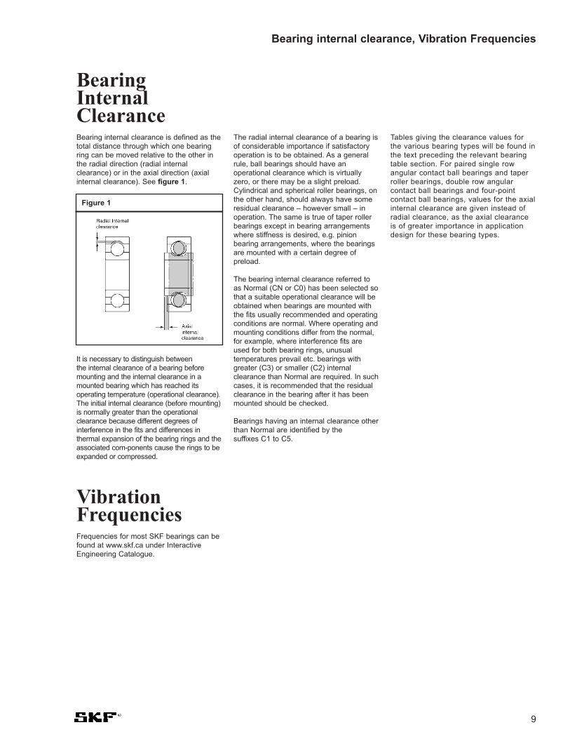
Bearing internal clearance, Vibration Frequencies
BearingInternalClearanceBearing internal clearance is defined as thetotal distance through which one bearingring can be moved relative to the other inthe radial direction (radial internalclearance) or in the axial direction (axialinternal clearance). See figure 1.
It is necessary to distinguish between the internal clearance of a bearing beforemounting and the internal clearance in amounted bearing which has reached itsoperating temperature (operational clearance).The initial internal clearance (before mounting)is normally greater than the operationalclearance because different degrees ofinterference in the fits and differences inthermal expansion of the bearing rings and theassociated com-ponents cause the rings to beexpanded or compressed.
The radial internal clearance of a bearing isof considerable importance if satisfactoryoperation is to be obtained. As a generalrule, ball bearings should have anoperational clearance which is virtuallyzero, or there may be a slight preload.Cylindrical and spherical roller bearings, onthe other hand, should always have someresidual clearance – however small – inoperation. The same is true of taper rollerbearings except in bearing arrangementswhere stiffness is desired, e.g. pinionbearing arrangements, where the bearingsare mounted with a certain degree ofpreload.
The bearing internal clearance referred toas Normal (CN or C0) has been selected sothat a suitable operational clearance will beobtained when bearings are mounted withthe fits usually recommended and operatingconditions are normal. Where operating andmounting conditions differ from the normal,for example, where interference fits areused for both bearing rings, unusualtemperatures prevail etc. bearings withgreater (C3) or smaller (C2) internalclearance than Normal are required. In suchcases, it is recommended that the residualclearance in the bearing after it has beenmounted should be checked.
Bearings having an internal clearance otherthan Normal are identified by the suffixes C1 to C5.
Tables giving the clearance values forthe various bearing types will be found inthe text preceding the relevant bearingtable section. For paired single rowangular contact ball bearings and taperroller bearings, double row angularcontact ball bearings and four-pointcontact ball bearings, values for the axialinternal clearance are given instead ofradial clearance, as the axial clearanceis of greater importance in applicationdesign for these bearing types.
VibrationFrequenciesFrequencies for most SKF bearings can befound at www.skf.ca under InteractiveEngineering Catalogue.
Figure 1

10
SKF Explorer
SKF ExplorerA new level of performanceOver the years, manufacturing andmaterials research and processimprovements have enabled machinecomponents to get smaller withoutdecreasing power output. With eachdevelopmental milestone, Engineers weregiven a choice; either downsize theapplication or increase power output. Thenew generation of SKF Explorer bearingsrepresents the next significant improvementin performance. But this is not just a shorthop to the next level. This is a quantumleap in bearing performance. Tests haveshown that these bearings will last up to 3times longer than the bearing you arecurrently using.
Improved materials enhance performance Developments in the steel making processhave created an extremely clean andhomogenous steel with a minimum numberof inclusions. This improved steel is so muchcleaner than the highest grades covered bypresent classification methods that SKFexperts developed new specifications with aview toward standardization.
To maximize the benefits of this improvedsteel, SKF developed new heat treatmentprocedures. These new procedures furtherimproved the wear resistance of SKFExplorer bearings. In fact, wear resistancewas improved so dramatically that SKFEngineers were not able to accuratelypredict life expectancy using existing lifecalculation methods. To enable users topredict bearing life more accurately, SKFhas done the following:
• Increased basic dynamic load ratings and• Added a factor to be considered when
calculating life using the SKF Life Method
For more information, please contact SKFApplication Engineering or visit www.skf.ca.
Reengineered for enduranceBy studying the inter-relationship of eachbearing component’s design, molecularstructure and finish, SKF scientists and Engineers were able to maximize theeffects of lubrication and minimize theeffects of friction, wear, contaminationand vibration. To do this, the SKFresearch team had to literally reengineereach component at either the micro ormolecular level, and then develop newprocedures to consistently manufacturethis new standard of excellence. Thesenew procedures have tightened themanufacturing tolerance for all com-ponents used in SKF Explorer bearings.
Since it's introduction in 1999, SKF hasbeen making the investments necessary toupgrade other bearing types to the SKFExplorer quality level. Bearing types includeAngular contact ball bearings, both singlerow and double row; Cylindrical rollerbearings, Spherical roller thrust bearingsand deep groove ball bearings. Dependingon the type, have been shown to reducevibrations, reduce heat, accommodatehigher loads and longer service life. In alltests performed, SKF Explorer bearingslasted considerably longer than competitorbearings including non-Explorer SKFbearings.
Now that these other bearing types areavailable in SKF Explorer quality, OEM'scan realize the full benefits of a completeSKF Explorer bearing arrangement. Forinstance an industrial gearbox manu-facturer can now build a unit thatcontains not just SKF ExplorerSphericals, but can also contain SKFExplorer Cylindricals and SKF ExplorerSpherical roller thrust bearings.
Note on SKF Explorer bearingsHigh performance SKF Explorer bearingsare shown with an asterisk in the producttables. SKF Explorer bearings retain thedesignation of the standard bearings,however, each bearing and its box aremarked with the name "EXPLORER".

New machine with same powerSKF Explorer makes it possible to use a smaller bear-ing size which allows:
• more compact machines,• higher speeds,
• smoother and quieter running,• less lubricant usage,
• reduced friction,and will create added value.
Existing machine
Switching to SKF Explorer bearings give:
• several times the service lifepreviously achieved,
• more machine uptime,• higher safety factor,• an appreciable reduction
of machine cycle costand, therefore, added value.
New machine with same or
increased powerThe higher carrying capacity of SKF
Explorer bearings allows the use of alighter series with same outside diameter and
increased bore diameter, so that:
• a stronger, or even hollow shaft can be used,• the total design can be stiffer and also cheaper,• system life is increased due to higher stiffness,
and machine cycle cost is significantly reduced.
Existingmachinewith increasedpower
Same size SKF Explorer bearingsallow power increases of 15 to 25% with:
• same service life,• same machine uptime,• same machine design,
and higher added value.
11
What SKF Explorer does for your machine
SKF Explorer

12
High PrecisionBearingsAll SKF bearings listed in this catalogue areprecision products conforming to thestringent tolerance requirements of ABEC 1or REBC 1. Certain ball bearings are madeto higher (ABEC 5) tolerances.
There are, however, applications withstricter demands for high running accuracyand rigidity, low frictional torque andoperating temperatures, and smalltemperature variations over a very widespeed range, such as machine toolspindles. The SKF precision catalogue5002 describes SKF high precisionbearings for such applications.
To meet the different demands foraccuracy, SKF high precision bearings aremade to a number of tolerance classes. Adescription of these is shown below.
High precisionangular contact ball bearingsThe SKF high precision angular contact ballbearings have been specially designed forgrinding spindle applications, combining radialand axial load-carrying ability in one bearing.
Their high precision means virtuallyvibration-free operation. Their low friction,due to groove optimization, means lower
Precision, New speed definition
SKF tolerance classes for high-precision bearings
SKF Boundary RunningTolerance Dimensions AccuracyClass ISO, ABMA ISO, ABMA
SP ISO 5, ABEC 5 ISO 4, ABEC 7
UP ISO 4, ABEC 7 ISO 2, ABEC 9
P4A ISO 4, ABEC 7 ISO 2, ABEC 91)
P4C ISO 4, ABEC 7 ISO 4, ABEC 7
PA9A ISO 2, ABEC 9 ISO 2, ABEC 9
1) Up to 120mm bore diameter, for larger sizes, ABEC 7 or better
Comparison of different standards
ABMA1) ISO SKFTolerance Tolerance StandardClass Class
ABEC 9 2 PA9A
ABEC 7 4 P4
ABEC 5 5 P5
1) ANSI/ABMA - American National Standards Institute/ Antifriction Bearing Manufacturers Association.
temperatures resulting in longer lubricantlife and longer bearing service life.
SKF high precision angular contact ballbearings are manufactured as standard totolerance class P4A, but may also besupplied to tolerance class PA9A.
Angular contact ball bearings are designed sothe direction of load through the balls formsan angle with the radial plane of the bearing.
See catalogue 5002.
In the new SKF 5000 General Catalogue,SKF has introduced new definitions forspeed ratings on bearings: Referencespeed and Limiting speed.
Reference speed The Reference speed is based on a temp-erature limit, in accordance with conditionsset out in ISO 15312. The different con-ditions for oil and grease lubrication areselected so that for both, the samereference speed is valid. Any deviation fromthese conditions must be considered inorder to determine the permissible speed.For full complement and sealed bearings no
reference speed is given, as the limitingspeed is less than the reference speed.This is done to avoid running the bearingsover an acceptable value.
Limiting speed The Limiting speed is a kinematic limit basedon the dynamic limitations of the bearingcomponents (e.g., cage design, rollingelement size, etc.). Limiting speeds are validfor the bearing design and standard cageexecution shown. It is possible under certainconditions to run the bearings at higherspeeds if some of the speed limiting factors
such as running accuracy, cage material anddesign, lubrication and heat dissipation canbe improved.
Some open ball bearings have very lowfriction and reference speeds listed mightbe higher than the limiting speeds.Therefore the permissible speed needs tobe calculated and compared to the limitingspeed. Always limit the bearing to the lowerof these 2 values.
See the General Catalogue 6000 onpages 108 and 114.
New SpeedDefinition

13
Dimensional guidelines for mounting
Shaft tolerances for bearings mounted on sleeves
Shaft Diameter and form tolerancesdiameterd h9 IT51) h10 IT71)
Nominal Deviations Deviationsover incl. high low max high low max
mm inch
10 18 0 -0.0017 0.0003 0 -0.0028 0.0007
18 30 0 -0.0020 0.0004 0 -0.0033 0.0008
30 50 0 -0.0024 0.0004 0 -0.0039 0.0010
50 80 0 -0.0029 0.0005 0 -0.0047 0.0012
80 120 0 -0.0034 0.0006 0 -0.0055 0.0014
120 180 0 -0.0039 0.0008 0 -0.0063 0.0016
180 250 0 -0.0045 0.0008 0 -0.0073 0.0018
250 315 0 -0.0051 0.0009 0 -0.0083 0.0021
315 400 0 -0.0055 0.0098 0 -0.0091 0.0022
400 500 0 -0.0061 0.0016 0 -0.0098 0.0025
500 630 0 -0.0069 0.0013 0 -0.0110 0.0028
630 800 0 -0.0079 0.0014 0 -0.0126 0.0031
800 1 000 0 -0.0090 0.0016 0 -0.0142 0.0035
1 000 1 250 0 -0.0102 0.0019 0 0.0165 0.0041
1) The recommendation is for IT5/2 or IT7/2, because the tolerance zone t is a radius, however in the table above the values relate to a nominal shaft diameter and are therefore not halved

14
Dimensional guidelines for mounting
MountingBearings withTapered BoreBearings with a tapered bore are alwaysmounted with an interference fit. Thereduction in radial internal clearance, or theaxial displacement of the inner ring on itstapered seating is used as a measure of thedegree of interference.
Suitable methods for mounting sphericalroller bearings with tapered bore are:
• measuring the clearance reduction,• measuring the lock nut tightening angle,• measuring the axial drive-up,• measuring the inner ring expansion.
Small bearings with a bore diameter up to100 mm can be properly mounted bymeasuring the lock nut tightening angle. Forlarger bearings the SKF Drive-up Method is
recommended. This method is moreaccurate and takes less time than the procedure based on clearance reduction orthe lock nut tightening angle. Measuring theinner ring expansion, i.e. applying the SKFSensorMount® Method, allows large sizebearings to be mounted simply, quickly andaccurately, since a sensor is integrated intothe bearing inner ring.
Measuring clearance reductionThe method using feeler gauges formeasuring the radial internal clearancebefore and after mounting bearings isapplicable for medium and large-sizedbearings. The clearance should always be measured between the outer ring andan unloaded roller (see fig 1). Beforemeasuring, rotate the inner or outer ring
a few times. Care must be taken to see thatboth bearing rings and the roller comple-ment are centrically arranged with respectto each other. For the first measurement, a blade should be selected which is slightlythinner than the minimum value for theclearance. The procedure should be repeated using slightly thicker blades eachtime until a certain resistance is felt whenmoving between
• outer ring and uppermost roller (a) – before mounting
• outer ring and lowest roller(b) – after mounting.
Guideline values for the permissible minimum clearance after mounting aregiven in table 1.
Figure 1

15
Dimensional guidelines for mounting
Table 1. Guideline values for reduction of radial internal clearance, axial drive-up and lock nut tightening angle
Bore Reduction of Axial drive-up1) Permissible residual2) Lock nutdiameter radial internal s radial clearance after tighteningd clearance Taper Taper mounting bearings angle
1:12 1:30 with initial clearance αover incl. min max min max min max Normal C3 C4 Taper 1:12
mm in in in degrees3)
24 30 0.0006 0.0008 0.0118 0.0138 - - 0.0006 0.0008 0.0014 11030 40 0.0008 0.0010 0.0138 0.0157 - - 0.0006 0.0010 0.0016 12040 50 0.0010 0.0012 0.0157 0.0177 - - 0.0008 0.0012 0.0020 130
50 65 0.0012 0.0016 0.0177 0.0236 0.1181 0.1575 0.0010 0.0014 0.0022 11065 80 0.0016 0.0020 0.0236 0.0276 0.1260 0.1654 0.0010 0.0016 0.0028 13080 100 0.0018 0.0024 0.0276 0.0354 0.0669 0.0866 0.0014 0.0020 0.0031 150
100 120 0.0020 0.0028 0.0295 0.0433 0.0748 0.1063 0.0020 0.0026 0.0039 –120 140 0.0026 0.0035 0.0433 0.0551 0.1063 0.1378 0.0022 0.0031 0.0043 –140 160 0.0030 0.0039 0.0472 0.0630 0.1181 0.1575 0.0022 0.0035 0.0051 –
160 180 0.0031 0.0043 0.0512 0.0669 0.1260 0.1654 0.0024 0.0039 0.0059 –180 200 0.0035 0.0051 0.0551 0.0787 0.1378 0.1969 0.0028 0.0039 0.0063 –200 225 0.0039 0.0055 0.0630 0.0866 0.1575 0.2165 0.0031 0.0047 0.0071 –
225 250 0.0043 0.0059 0.0669 0.0945 0.1654 0.2362 0.0035 0.0051 0.0079 –250 280 0.0047 0.0067 0.0748 0.1063 0.1850 0.2638 0.0039 0.0055 0.0087 –280 315 0.0051 0.0075 0.0787 0.1181 0.1969 0.2953 0.0043 0.0059 0.0094 –
315 355 0.0059 0.0083 0.0945 0.1299 0.2362 0.3228 0.0047 0.0067 0.0102 –355 400 0.0067 0.0091 0.1024 0.1417 0.2559 0.3543 0.0051 0.0075 0.0114 –400 450 0.0079 0.0102 0.1220 0.1575 0.3031 0.3937 0.0051 0.0079 0.0122 –
450 500 0.0083 0.0110 0.1299 0.1732 0.3228 0.4331 0.0063 0.0091 0.0138 –500 560 0.0094 0.0126 0.1457 0.1969 0.3622 0.4921 0.0067 0.0098 0.0142 –560 630 0.0102 0.0138 0.1575 0.2126 0.3937 0.5315 0.0079 0.0114 0.0161 –
630 710 0.0118 0.0157 0.1811 0.2441 0.4528 0.6102 0.0083 0.0122 0.0177 –710 800 0.0134 0.0177 0.2087 0.2756 0.5236 0.6890 0.0091 0.0138 0.0201 –800 900 0.0146 0.0197 0.2244 0.3071 0.5630 0.7677 0.0106 0.0154 0.0224 –
900 1 000 0.0161 0.0217 0.2480 0.3346 0.6220 0.8268 0.0118 0.0169 0.0252 –1 000 1 120 0.0177 0.0236 0.2677 0.3543 0.6693 0.9055 0.0126 0.0189 0.0276 –1 120 1 250 0.0193 0.0256 0.2913 0.3858 0.7283 0.9843 0.0134 0.0213 0.0303 –
1 250 1 400 0.0217 0.0283 0.3268 0.4252 0.8268 1.0630 0.0142 0.0232 0.0331 –1 400 1 600 0.0236 0.0315 0.3583 0.4685 0.8937 1.1732 0.0157 0.0256 0.0362 –1 600 1 800 0.0264 0.0354 0.4016 0.5276 1.0000 1.3228 0.0173 0.0283 0.0402 –
1) Valid only for solid steel shafts and general application. Not valid for the SKF Drive-up Method2) The residual clearance must be checked in cases where the initial radial internal clearance is in the lower
half of the residual clearance must not be less than the minimum values quoted above3) 1:12 tapers only
The locknut tightening method is valid for mounting on adapter sleeves only.
16
Dimensional guidelines for mounting
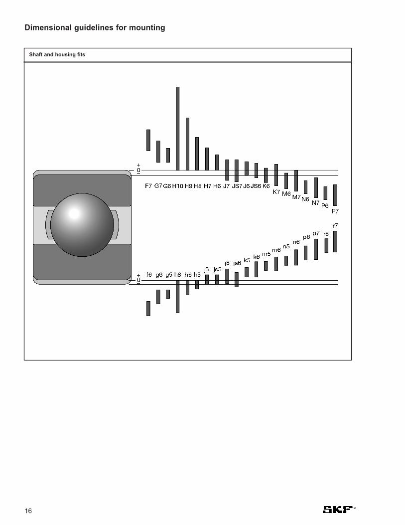
Shaft and housing fits

Fits for solid steel shafts Radial bearings with cylindrical bore (except inch size bearings)
Conditions Examples Shaft diameter, mm ToleranceBall Cylindrical CARB andbearings and taper spherical
roller rollerbearings bearings
Rotating inner ring load or direction of load indeterminate
Light and variable Conveyors, lightly (18) to 100 < 40 – j6loads (P < 0.06 C) loaded gearbox (100) to 140 (40) to 100 k6
bearings
Normal and heavy Bearing applications < 18 – – j5loads (P > 0.06 C) generally, (18) to 100 < 40 < 40 k5 (k6)1)
electric motors, (100) to 140 (40) to 100 (40) to 65 m5 (m6)1)
turbines, pumps, (140) to 200 (100) to 140 (65) to 100 m6internal combustion (200) to 280 (140) to 200 (100) to 140 n6engines, gearing, – (200) to 400 (140) to 280 p6woodworking machines – – (280) to 500 r62)
– – > 500 r72)
Very heavy loads and Axleboxes for heavy – (50) to 140 (50) to 100 n62)
shock loads with railway vehicles, traction – (140) to 200 (100) to 140 p62)
difficult working motors, rolling mills – > 200 > 140 r62)
conditions (P > 0.12 C)
High demands on running Machine tools 8 to 240 – – js4accuracy with light loads – 25 to 40 – js4 (j5)3)
(P < or = 0.06 C) – (40) to 140 – k4 (k5)3)
– (140) to 200 – m53)
– (200) to 500 – n53)
Stationary inner ring load
Easy axial displacement Wheels on non-rotating g64)
of inner ring on shaft axlesdesirable
Easy axial displacement Tension pulleys, ropeof inner ring on shaft sheaves h6unnecessary
Axial loads onlyBearing applications of < 250 < 250 < 250 j6all kinds > 250 > 250 > 250 js6
1) The tolerances in brackets are generally used for taper roller bearings and single row angular contact ball bearings, they can also be used for other types of bearing where speeds are moderate and the effect of bearing internal clearance variation is not significant
2) Bearings with radial internal clearance greater than Normal may be necessary3) The tolerances in brackets apply to taper roller bearings. For lightly loaded taper roller bearings adjusted via the inner ring, js5 or js6 should be used 4) Tolerance f6 can be selected for large bearings to provide easy displacement
17
Fits for solid steel shafts Thrust bearings
Conditions Shaft diameter, Tolerancemm
Axial loads only
Thrust ball bearings – h6Cylindrical roller thrust bearings – h6 (h8)Cylindrical roller and cage thrust assemblies – h8
Combined radial and axial loads acting on spherical roller thrust bearings
Stationary load on shaft washer < 250 j6> 250 js6
Rotating load on shaft washer, < 200 k6or direction of load indeterminate (200) to 400 m6
> 400 n6
Dimensional guidelines for mounting

18
Fits for cast iron and steel housings Radial bearings – non-split housings
Conditions Examples Tolerance Displacement of outer ring
Rotating outer ring load
Heavy loads on bearings Roller bearing wheel hubs, P7 Cannot be displaced
in thin-walled housings, big-end bearings
heavy shock loads
(P > 0.12 C)
Normal and heavy loads Ball bearing wheel hubs, N7 Cannot be displaced
(P > 0.06 C) big-end bearings, crane
travelling wheels
Light and variable loads Conveyor rollers, rope sheaves, M7 Cannot be displaced
(P < 0.06 C) belt tensioner pulleys
Direction of load indeterminate
Heavy shock loads Electric traction motors M7 Cannot be displaced
Normal and heavy loads Electric motors, pumps, K7 Cannot be displaced
(P > 0.06 C), axial dis- crankshaft bearings as a rule
placement of outer ring
unnecessary
Accurate or quiet running1)
Ball bearings Small electric motors J62) Can be displaced
Taper roller bearings When adjusted via the outer ring JS5 –
Axially located outer ring K5 –
Rotating outer ring load M5 –
1) For high-precision bearings to tolerance class P5 or better, other recommendations apply (see the SKF catalogue “High-precision bearings”)
2) When easy displacement is required use H6 instead of J6
Dimensional guidelines for mounting

19
Fits for cast iron and steel housings Thrust bearings
Conditions Tolerance Remarks
Axial loads only
Thrust ball bearings H8 For less accurate bearing arrangements therecan be a radial clearance of up to 0.001 D
Cylindrical roller thrust bearings H7 (H9)
Cylindrical roller and cage thrust H10assemblies
Spherical roller thrust bearings – Housing washer must be fitted with adequate where separate bearings provide radial clearance so that no radial load radial location whatsoever can act on the thrust bearings
Combined radial and axial loads onspherical roller thrust bearings
Stationary load on housing washer H7 See also “Design of associated components” in section “Spherical roller thrust bearings”on page 193.
Rotating load on housing washer M7
Dimensional guidelines for mounting
Fits for cast iron and steel housings Radial bearings – split or non-split housings
Conditions Examples Tolerance Displacement of outer ring
Direction of load indeterminate
Light and normal loads Medium-sized electrical J7 Can be displaced as a rule(P < 0.12 C), axial dis- machines, pumps, placement of outer ring crankshaft bearingsdesirable
Stationary outer ring load
Loads of all kinds General engineering, H71) Can be displacedrailway axleboxes
Light and normal loads General engineering H8 Can be displaced(P < 0.12 C) with simple working conditions
Heat conduction through Drying cylinders, large G72) Can be displacedshaft electrical machines
with spherical roller bearings
1) For large bearings (D > 250 mm) and temperature differences between outer ring and housing > 10°C, G7 should be used instead of H72) For large bearings (D > 250 mm) and temperature differences between outer ring and housing > 10°C, F7 should be used instead of G7

20
Mounting information: Shaft bearing-seat diameters (in inches)
Bearing Bore Diameter g6 h6 h5 j5 j6 k5
Shaft. Dia. fit in Shaft. Dia. fit in Shaft. Dia. fit in Shaft. Dia. fit in Shaft. Dia. fit in Shaft. Dia. fit inmm Inches 0.0000" 0.0000" 0.0000" 0.0000" 0.0000" 0.0000"
Max Min Max Min Max Min Max Min Max Min Max Min Max Min
4 0.1575 0.1572 0.1573 0.1570 5L 0.1575 0.1572 3L 0.1575 0.1573 2L 0.1576 0.1574 1L 0.1577 0.1574 1L 0.1577 0.1575 0T5 0.1969 0.1966 0.1967 0.1964 1T 0.1969 0.1966 3T 0.1969 0.1967 3T 0.1970 0.1968 4T 0.1971 0.1968 5T 0.1971 0.1969 5T6 0.2362 0.2359 0.2360 0.2357 0.2362 0.2359 0.2362 0.2360 0.2363 0.2361 0.2364 0.2361 0.2364 0.2362
7 0.2756 0.2753 0.2754 0.2750 6L 0.2756 0.2752 4L 0.2756 0.2754 2L 0.2758 0.2755 1L 0.2759 0.2755 1L 0.2759 0.2756 0T8 0.3150 0.3147 0.3148 0.3144 1T 0.3150 0.3146 3T 0.3150 0.3148 3T 0.3152 0.3149 5T 0.3153 0.3149 6T 0.3153 0.3150 6T9 0.3543 0.3540 0.3541 0.3537 0.3543 0.3539 0.3543 0.3541 0.3545 0.3542 0.3546 0.3542 0.3546 0.354310 0.3937 0.3934 0.3935 0.3931 0.3937 0.3933 0.3937 0.3935 0.3939 0.3936 0.3940 0.3936 0.3940 0.3937
12 0.4724 0.4721 0.4722 0.4717 7L 0.4724 0.4720 4L 0.4724 0.4721 3L 0.4726 0.4723 1L 0.4727 0.4723 1L 0.4728 0.4724 0T15 0.5906 0.5903 0.5904 0.5899 1T 0.5906 0.5902 3T 0.5906 0.5903 3T 0.5908 0.5905 5T 0.5909 0.5905 6T 0.5910 0.5906 7T17 0.6693 0.6690 0.6691 0.6686 0.6693 0.6689 0.6693 0.6690 0.6695 0.6692 0.6696 0.6692 0.6697 0.6693
20 0.7874 0.7870 0.7871 0.7866 8L 0.7874 0.7869 5L 0.7874 0.7870 4L 0.7876 0.7872 2L 0.7878 0.7872 2L 0.7878 0.7875 1T25 0.9843 0.9839 0.9840 0.9835 1T 0.9843 0.9838 4T 0.9843 0.9839 4T 0.9845 0.9841 6T 0.9847 0.9841 8T 0.9847 0.9844 8T30 1.1811 1.1807 1.1808 1.1803 1.1811 1.1806 1.1811 1.1807 1.1813 1.1809 1.1815 1.1809 1.1815 1.1812
35 1.3780 1.3775 1.3776 1.3770 10L 1.3780 1.3774 6L 1.3780 1.3776 4L 1.3782 1.3778 2L 1.3784 1.3778 2L 1.3785 1.3781 1T40 1.5748 1.5743 1.5744 1.5738 1T 1.5748 1.5742 5T 1.5748 1.5744 5T 1.5750 1.5746 7T 1.5752 1.5746 9T 1.5753 1.5749 10T45 1.7717 1.7712 1.7713 1.7707 1.7717 1.7711 1.7717 1.7713 1.7719 1.7715 1.7721 1.7715 1.7722 1.771850 1.9685 1.9680 1.9681 1.9675 1.9685 1.9679 1.9685 1.9681 1.9687 1.9683 1.9689 1.9683 1.9690 1.9686
55 2.1654 2.1648 2.1650 2.1643 11L 2.1654 2.1647 7L 2.1654 2.1649 5L 2.1656 2.1651 3L 2.1659 2.1651 3L 2.1660 2.1655 1T60 2.3622 2.3616 2.3618 2.3611 2T 2.3622 2.3615 6T 2.3622 2.3617 6T 2.3624 2.3619 8T 2.3627 2.3619 11T 2.3628 2.3623 12T65 2.5591 2.5585 2.5587 2.5580 2.5591 2.5584 2.5591 2.5586 2.5593 2.5588 2.5596 2.5588 2.5597 2.559270 2.7559 2.7553 2.7555 2.7548 2.7559 2.7552 2.7559 2.7554 2.7561 2.7556 2.7564 2.7556 2.7565 2.756075 2.9528 2.9522 2.9524 2.9517 2.9528 2.9521 2.9528 2.9523 2.9530 2.9525 2.9533 2.9525 2.9534 2.952980 3.1496 3.1490 3.1492 3.1485 3.1496 3.1489 3.1496 3.1491 3.1498 3.1493 3.1501 3.1493 3.1502 3.1497
85 3.3465 3.3457 3.3460 3.3452 13L 3.3465 3.3456 9L 3.3465 3.3459 6L 3.3467 3.3461 4L 3.3470 3.3461 4L 3.3472 3.3466 1T90 3.5433 3.5425 3.5428 3.5420 3T 3.5433 3.5424 8T 3.5433 3.5427 8T 3.5435 3.5429 10T 3.5438 3.5429 13T 3.5440 3.5434 15T95 3.7402 3.7394 3.7397 3.7389 3.7402 3.7393 3.7402 3.7396 3.7404 3.7398 3.7407 3.7398 3.7409 3.7403100 3.9370 3.9362 3.9365 3.9357 3.9370 3.9361 3.9370 3.9364 3.9372 3.9366 3.9375 3.9366 3.9377 3.9371105 4.1339 4.1331 4.1334 4.1326 4.1339 4.1330 4.1339 4.1333 4.1341 4.1335 4.1344 4.1335 4.1346 4.1340110 4.3307 4.3299 4.3302 4.3294 4.3307 4.3298 4.3307 4.3301 4.3309 4.3303 4.3312 4.3303 4.3314 4.3308115 4.5276 4.5268 4.5271 4.5263 4.5276 4.5267 4.5276 4.5270 4.5278 4.5272 4.5281 4.5272 4.5283 4.5277120 4.7244 4.7236 4.7239 4.7231 4.7244 4.7235 4.7244 4.7238 4.7246 4.7240 4.7249 4.7240 4.7251 4.7245
125 4.9213 4.9203 4.9207 4.9198 15L 4.9213 4.9203 10L 4.9213 4.9206 7L 4.9216 4.9209 4L 4.9219 4.9209 4L 4.9221 4.9214 1T130 5.1181 5.1171 5.1175 5.1166 4T 5.1181 5.1171 10T 5.1181 5.1174 10T 5.1184 5.1177 13T 5.1187 5.1177 16T 5.1189 5.1182 18T140 5.5118 5.5108 5.5112 5.5103 5.5118 5.5108 5.5118 5.5111 5.5121 5.5114 5.5124 5.5114 5.5126 5.5119150 5.9055 5.9045 5.9049 5.9040 5.9055 5.9045 5.9055 5.9048 5.9058 5.9051 5.9061 5.9051 5.9063 5.9056160 6.2992 6.2982 6.2986 6.2977 6.2992 6.2982 6.2992 6.2985 6.2995 6.2988 6.2998 6.2988 6.3000 6.2993170 6.6929 6.6919 6.6923 6.6914 6.6929 6.6919 6.6929 6.6922 6.6932 6.6925 6.6935 6.6925 6.6937 6.6930180 7.0866 7.0856 7.0860 7.0851 7.0866 7.0856 7.0866 7.0859 7.0869 7.0862 7.0872 7.0862 7.0874 7.0867
190 7.4803 7.4791 7.4797 7.4786 17L 7.4803 7.4792 11L 7.4803 7.4795 8L 7.4806 7.4798 5L 7.4809 7.4798 5L 7.4812 7.4805 2T200 7.8740 7.8728 7.8734 7.8723 6T 7.8740 7.8729 12T 7.8740 7.8732 12T 7.8743 7.8735 15T 7.8746 7.8735 18T 7.8749 7.8742 21T
220 8.6614 8.6602 8.6608 8.6597 8.6614 8.6603 8.6614 8.6606 8.6617 8.6609 8.6620 8.6609 8.6623 8.6616
240 9.4488 9.4476 9.4482 9.4471 9.4488 9.4477 9.4488 9.4480 9.4491 9.4483 9.4494 9.4483 9.4497 9.4490250 9.8425 9.8413 9.8419 9.8408 9.8425 9.8414 9.8425 9.8417 9.8428 9.8420 9.8431 9.8420 9.8434 9.8427
260 10.2362 10.2348 10.2355 10.2343 19L 10.2362 10.2349 13L 10.2362 10.2353 9L 10.2365 10.2356 6L 10.2368 10.2356 6L 10.2373 10.2364 2T280 11.0236 11.0222 11.0229 11.0217 7T 11.0236 11.0223 14T 11.0236 11.0225 14T 11.0239 11.0230 17T 11.0242 11.0230 20T 11.0247 11.0238 25T
300 11.8110 11.8096 11.8103 11.8091 11.8110 11.8097 11.8110 11.8101 11.8113 11.8104 11.8116 11.8104 11.8121 11.8112310 12.2047 12.2033 12.2040 12.2028 12.2047 12.2034 12.2047 12.2038 12.2050 12.2041 12.2053 12.2041 12.2058 12.2049
320 12.5984 12.5968 12.5977 12.5963 21L 12.5984 12.5970 14L 12.5984 12.5974 10L 12.5987 12.5977 7L 12.5991 12.5977 7L 12.5995 12.5986 2T340 13.3858 13.3842 13.3851 13.3837 9T 13.3858 13.3844 16T 13.3858 13.3848 16T 13.3861 13.3851 19T 13.3865 13.3851 23T 13.3869 13.3860 27T350 13.7795 13.7779 13.7788 13.7774 13.7795 13.7781 13.7795 13.7785 13.7798 13.7788 13.7802 13.7788 13.7806 13.7797
360 14.1732 14.1716 14.1725 14.1711 14.1732 14.1718 14.1732 14.1722 14.1735 14.1725 14.1739 14.1725 14.1743 14.1734380 14.9606 14.9590 14.9599 14.9585 14.9606 14.9592 14.9606 14.9596 14.9609 14.9599 14.9613 14.9599 14.9617 14.9608400 15.7480 15.7464 15.7473 15.7459 15.7480 15.7466 15.7480 15.7470 15.7483 15.7473 15.7487 15.7473 15.7491 15.7482
420 16.5354 16.5336 16.5346 16.5330 24L 16.5354 16.5338 16L 16.5354 16.5343 11L 16.5357 16.5346 8L 16.5362 16.5346 8L 16.5367 16.5356 2T440 17.3228 17.3210 17.3220 17.3204 10T 17.3228 17.3212 18T 17.3228 17.3217 18T 17.3231 17.3220 21T 17.3236 17.3220 26T 17.3241 17.3230 31T
460 18.1102 18.1084 18.1094 18.1078 18.1102 18.1086 18.1102 18.1091 18.1105 18.1094 18.1110 18.1094 18.1115 18.1104480 18.8976 18.8958 18.8968 18.8952 18.8976 18.8960 18.8976 18.8965 18.8979 18.8968 18.8984 18.8968 18.8989 18.8978500 19.6850 19.6832 19.6842 19.6826 19.6850 19.6834 19.6850 19.6839 19.6853 19.6842 19.6858 19.6842 19.6863 19.6852
530 20.8661 20.8641 20.8652 20.8635 26L 20.8661 20.8644 17L 20.8664 20.8652 9L 20.8670 20.8652 9L 20.8673 20.8661 0T560 22.0472 22.0452 22.0463 22.0446 11T 22.0472 22.0455 20T 22.0475 22.0463 23T 22.0481 22.0463 29T 22.0484 22.0472 32T
600 23.6220 23.6200 23.6211 23.6194 23.6220 23.6203 23.6223 23.6211 23.6229 23.6211 23.6232 23.6220630 24.8031 24.8011 24.8022 24.8005 24.8031 24.8014 24.8034 24.8023 24.8040 24.8012 24.8043 24.8031
660 25.9843 25.9813 25.9834 25.9814 29L 25.9843 25.9823 20L 25.9847 25.9833 10L 25.9853 25.9833 10L 25.9857 25.9843 0T670 26.3780 26.3750 26.3771 26.3751 21T 26.3780 26.3760 30T 26.3784 26.3770 34T 26.3790 26.3770 40T 26.3794 26.3780 44T710 27.9528 27.9498 27.9519 27.9499 27.9528 27.9508 27.9532 27.9518 27.9538 27.9518 27.9542 27.9528
750 29.5276 29.5246 29.5267 29.5247 29.5276 29.5256 29.5280 29.5266 29.5286 29.5266 29.5290 29.5276780 30.7087 30.7057 30.7078 30.7058 30.7087 30.7067 30.7091 30.7077 30.7097 30.7077 30.7101 30.7087800 31.4961 31.4931 31.4952 31.4932 31.4961 31.4941 31.4965 31.4951 31.4971 31.4951 31.4975 31.4961
850 33.4646 33.4607 33.4636 33.4614 32L 33.4646 33.4624 22L 33.4651 33.4635 11L 33.4657 33.4635 11L 33.4662 33.4646 0T900 35.4331 35.4292 35.4321 35.4299 29T 35.4331 35.4309 39T 35.4336 35.4320 44T 35.4342 35.4320 50T 35.4347 35.4331 55T
950 37.4016 37.3977 37.4006 37.3984 37.4016 37.3994 37.4021 37.4005 37.4027 37.4005 37.4032 37.40161000 39.3701 39.3662 39.3691 39.3669 39.3701 39.3679 39.3706 39.3690 39.3712 39.3690 39.3717 39.3701
1060 41.7323 41.7274 41.7312 41.7286 37L 41.7323 41.7297 26L 41.7328 41.7310 13L 41.7336 41.7310 13L 41.7341 41.7323 0T1120 44.0945 44.0896 44.0934 44.0908 38T 44.0945 44.0919 49T 44.0950 44.0932 54T 44.0958 44.0932 62T 44.0963 44.0945 67T
1180 46.4567 46.4518 46.4556 46.4530 46.4567 46.4541 46.4572 46.4554 46.4580 46.4554 46.4585 46.45671250 49.2126 49.2077 49.2115 49.2089 49.2126 49.2100 49.2131 49.2113 49.2139 49.2113 49.2144 49.2126
Note: T indicates tight fit. L indicates loose fit.

21
Mounting information: Shaft bearing-seat diameters (in inches)
Brg. k6 m5 m6 n6 p6 r6 r7
Bore Shaft. Dia. fit in Shaft. Dia. fit in Shaft. Dia. fit in Shaft. Dia. fit in Shaft. Dia. fit in Shaft. Dia. fit in Shaft. Dia. fit inDia. 0.0000" 0.0000" 0.0000" 0.0000" 0.0000" 0.0000" 0.0000"mm Max Min Max Min Max Min Max Min Max Min Max Min Max Min
4 0.1579 0.1575 0T 0.1579 0.1577 2T 0.1580 0.1577 2T 0.1581 0.1578 3T5 0.1973 0.1969 7T 0.1973 0.1971 7T 0.1974 0.1971 8T 0.1975 0.1972 9T6 0.2366 0.2362 0.2366 0.2364 0.2367 0.2364 0.2368 0.2365
7 0.2760 0.2756 0T 0.2761 0.2758 2T 0.2762 0.2758 2T 0.2764 0.2760 4T8 0.3154 0.3150 7T 0.3155 0.3152 8T 0.3156 0.3152 9T 0.3158 0.3154 11T9 0.3547 0.3543 0.3548 0.3545 0.3549 0.3545 0.3551 0.354710 0.3941 0.3937 0.3942 0.3939 0.3943 0.3939 0.3945 0.3941
12 0.4729 0.4724 0T 0.4730 0.4727 3T 0.4731 0.4727 3T 0.4733 0.4729 5T15 0.5911 0.5906 8T 0.5912 0.5909 9T 0.5913 0.5909 10T 0.5915 0.5911 12T17 0.6698 0.6693 0.6699 0.6696 0.6700 0.6696 0.6702 0.6698
20 0.7880 0.7875 1T 0.7881 0.7877 3T 0.7882 0.7877 3T 0.7885 0.7880 6T25 0.9849 0.9844 10T 0.9850 0.9846 11T 0.9851 0.9846 12T 0.9854 0.9849 15T30 1.1817 1.1812 1.1818 1.1814 1.1819 1.1814 1.1822 1.1817
35 1.3787 1.3781 1T 1.3788 1.3784 4T 1.3790 1.3784 4T 1.3793 1.3787 7T40 1.5755 1.5749 12T 1.5756 1.5752 13T 1.5758 1.5752 15T 1.5761 1.5755 18T45 1.7724 1.7718 1.7725 1.7721 1.7727 1.7721 1.7730 1.772450 1.9692 1.9686 1.9693 1.9689 1.9695 1.9689 1.9698 1.9692
55 2.1662 2.1655 1T 2.1663 2.1658 4T 2.1666 2.1658 4T 2.1669 2.1662 8T60 2.3630 2.3623 14T 2.3631 2.3626 15T 2.3634 2.3626 18T 2.3637 2.3630 21T65 2.5599 2.5592 2.5600 2.5595 2.5603 2.5595 2.5606 2.559970 2.7567 2.7560 2.7568 2.7563 2.7571 2.7563 2.7574 2.756775 2.9536 2.9529 2.9537 2.9532 2.9540 2.9532 2.9543 2.953680 3.1504 3.1497 3.1505 3.1500 3.1508 3.1500 3.1511 3.1504
85 3.3475 3.3466 1T 3.3476 3.3470 5T 3.3479 3.3470 5T 3.3483 3.3474 9T 3.3488 3.3480 15T90 3.5443 3.5434 18T 3.5444 3.5438 19T 3.5447 3.5438 22T 3.5451 3.5442 26T 3.5456 3.5448 31T95 3.7412 3.7403 3.7413 3.7407 3.7416 3.7407 3.7420 3.7411 3.7425 3.7417100 3.9380 3.9371 3.9381 3.9375 3.9384 3.9375 3.9388 3.9379 3.9393 3.9385105 4.1349 4.1340 4.1350 4.1344 4.1353 4.1344 4.1357 4.1348 4.1362 4.1354110 4.3317 4.3308 4.3318 4.3312 4.3321 4.3312 4.3325 4.3316 4.3330 4.3322115 4.5286 4.5277 4.5287 4.5281 4.5290 4.5281 4.5294 4.5285 4.5299 4.5291120 4.7254 4.7245 4.7255 4.7249 4.7258 4.7249 4.7262 4.7253 4.7267 4.7259
125 4.9224 4.9214 1T 4.9226 4.9219 6T 4.9229 4.9219 6T 4.9233 4.9224 11T 4.9240 4.9230 17T 4.9248 4.9239 26T130 5.1192 5.1182 21T 5.1194 5.1187 23T 5.1197 5.1187 26T 5.1201 5.1192 30T 5.1208 5.1198 37T 5.1216 5.1207 45T140 5.5129 5.5119 5.5131 5.5124 5.5134 5.5124 5.5138 5.5129 5.5145 5.5135 5.5153 5.5144150 5.9066 5.9056 5.9068 5.9061 5.9071 5.9061 5.9075 5.9066 5.9082 5.9072 5.9090 5.9081160 6.3003 6.2993 6.3005 6.2998 6.3008 6.2998 6.3012 6.3003 6.3019 6.3009 6.3027 6.3018170 6.6940 6.6930 6.6942 6.6935 6.6945 6.6935 6.6949 6.6940 6.6956 6.6946 6.6964 6.6955180 7.0877 7.0867 7.0879 7.0872 7.0882 7.0872 7.0886 7.0877 7.0893 7.0883 7.0901 7.0892
190 7.4816 7.4805 2T 7.4818 7.4810 7T 7.4821 7.4810 7T 7.4827 7.4815 12T 7.4834 7.4823 20T 7.4845 7.4833 30T200 7.8753 7.8742 25T 7.8755 7.8747 27T 7.8758 7.8747 30T 7.8764 7.8752 36T 7.8771 7.8760 43T 7.8782 7.8770 54T
220 8.6627 8.6616 8.6629 8.6621 8.6632 8.6621 8.6638 8.6626 8.6645 8.6634 8.6657 8.6645 31T/55T 8.6664 8.6645 31T/62T
240 9.4501 9.4490 9.4503 9.4495 9.4506 9.4495 9.4512 9.4500 9.4519 9.4508 9.4532 9.4521 33T 9.4539 9.4521 33T250 9.8438 9.8427 9.8440 9.8432 9.8443 9.8432 9.8449 9.8437 9.8456 9.8445 9.8469 9.8458 56T 9.8476 9.4858 63T
260 10.2376 10.2364 2T 10.2379 10.2370 8T 10.2382 10.2370 8T 10.2388 10.2375 13T 10.2397 10.2384 22T 10.2412 10.2399 37T 10.2419 10.2399 37T280 11.0250 11.0238 28T 11.0253 11.0244 31T 11.0256 11.0244 34T 11.0262 11.0249 40T 11.0271 11.0258 49T 11.0286 11.0273 64T 11.0293 11.0273 71T
300 11.8124 11.8112 11.8127 11.8118 11.8130 11.8118 11.8136 11.8123 11.8145 11.8132 11.8161 11.8149 39T 11.8169 11.8149 39T310 12.2061 12.2049 12.2064 12.2055 12.2067 12.2055 12.2073 12.2060 12.2082 12.2069 12.2098 12.2086 65T 12.2106 12.2086 73T
320 12.5999 12.5986 2T 12.6002 12.5992 8T 12.6006 12.5992 8T 12.6013 12.5999 15T 12.6023 12.6008 24T 12.6041 12.6027 43T 12.6049 12.6027 43T340 13.3873 13.3860 31T 13.3876 13.3866 34T 13.3880 13.3866 38T 13.3887 13.3873 45T 13.3897 13.3882 55T 13.3915 13.3901 73T 13.3923 13.3901 81T350 13.7810 13.7797 13.7813 13.7803 13.7817 13.7803 13.7824 13.7810 13.7834 13.7819 13.7852 13.7838 13.7860 13.7838
360 14.1747 14.1734 14.1750 14.1740 14.1754 14.1740 14.1761 14.1747 14.1771 14.1756 14.1791 14.1777 45T 14.1799 14.1777 45T380 14.9621 14.9608 14.9624 14.9614 14.9628 14.9614 14.9635 14.9621 14.9645 14.9630 14.9665 14.9651 75T 14.9673 14.9651 83T400 15.7495 15.7482 15.7498 15.7488 15.7502 15.7488 15.7509 15.7495 15.7519 15.7504 15.7539 15.7525 15.7547 15.7525
420 16.5371 16.5356 2T 16.5374 16.5363 9T 16.5379 16.5363 9T 16.5385 16.5370 16T 16.5397 16.5381 27T 16.5419 16.5404 50T 16.5428 16.5404 50T440 17.3245 17.3230 35T 17.3248 17.3237 38T 17.3253 17.3237 43T 17.3259 17.3244 49T 17.3271 17.3255 61T 17.3293 17.3278 83T 17.3302 17.3278 92T
460 18.1119 18.1104 18.1122 18.1111 18.1127 18.1111 18.1133 18.1118 18.1145 18.1129 18.1170 18.1154 52T 18.1179 18.1154 52T480 18.8993 18.8978 18.8996 18.8985 18.9001 18.8985 18.9007 18.8992 18.9019 18.9003 18.9044 18.9028 86T 18.9053 18.9028 95T500 19.6867 19.6852 19.6870 19.6859 19.6875 19.6859 19.6881 19.6866 19.6893 19.6877 19.6918 19.6902 19.6927 19.6902
530 20.8678 20.8661 0T 20.8683 20.8671 10T 20.8695 20.8678 17T 20.8709 20.8692 31T 20.8737 20.8720 59T 20.8748 20.8720 59T560 22.0489 22.0472 37T 22.0494 22.0482 42T 22.0506 22.0489 54T 22.0520 22.0503 68T 22.0548 22.0531 96T 22.0559 22.0531 107T
600 23.6237 23.6220 23.6242 23.6230 23.6254 23.6237 23.6268 23.6251 23.6298 23.6281 61T 23.6309 23.6281 61T630 24.8048 24.8031 24.8053 24.8041 24.8065 24.8048 24.8079 24.8062 24.8109 24.8092 98T 24.8120 24.8092 109T
660 25.9862 25.9843 0T 25.9869 25.9855 12T 25.9682 25.9663 20T 25.9897 25.9878 35T 25.9932 25.9912 69T 25.9943 25.9912 69T670 26.3799 26.3780 49T 26.3806 26.3792 56T 26.3819 26.3800 69T 26.3834 26.3815 84T 26.3869 26.3849 119T 26.3880 26.3849 130T710 27.9447 27.9528 27.9554 27.9540 27.9567 27.9548 27.9582 27.9563 27.9617 27.9597 27.9628 27.9597
750 29.5295 29.5276 29.5302 29.5288 29.5315 29.5296 29.5330 29.5311 29.5369 29.5349 73T 29.5380 29.5349 73T780 30.7106 30.7087 30.7113 30.7099 30.7126 30.7107 30.7141 30.7122 30.7180 30.7160 123T 30.7191 30.7160 134T800 31.4980 31.4961 31.4987 31.4973 31.5000 31.4981 31.5015 31.4996 31.5054 31.5034 31.5065 31.5034
850 33.4668 33.4646 0T 33.4675 33.4659 13T 33.4690 33.4668 22T 33.4707 33.4685 39T 33.4751 33.4729 83T 33.4764 33.4729 83T900 35.4353 35.4331 61T 35.4360 35.4344 68T 35.4375 35.4353 83T 35.4392 35.4370 100T 35.4436 35.4414 144T 35.4449 35.4414 157T
950 37.4038 37.4016 37.4045 37.4029 37.4060 37.4038 37.4077 37.4055 37.4125 37.4103 87T 37.4138 37.4103 87T1000 39.3723 39.3701 39.3730 39.3714 39.3745 39.3723 39.3762 39.3740 39.3810 37.3788 148T 39.3823 39.3788 161T
1060 41.7349 41.7323 0T 41.7357 41.7339 16T 41.7375 41.7349 26T 41.7396 41.7370 47T 41.7447 41.7421 98T 41.7463 41.7421 98T1120 44.0971 44.0945 75T 44.0979 44.0961 83T 44.0997 44.0971 101T 44.1018 44.0992 122T 44.1069 44.1043 173T 44.1085 44.1043 189T
1180 46.4593 46.4567 46.4601 46.4583 46.4619 46.4593 46.4640 46.4614 46.4695 46.4669 102T 46.4711 46.4669 102T1250 49.2152 49.2126 49.2160 49.2142 49.2178 49.2152 49.2199 49.2173 49.2254 49.2228 177T 49.2270 49.2228 193T
Note: T indicates tight fit. L indicates loose fit.

22
Mounting information: Housing bearing-seat diameters (in inches)
Bearing Outside Diameter F7 G7 H8 H7 H6
mm Inches Housing Bore Fit in Housing Bore Fit in Housing Bore Fit in Housing Bore Fit in Housing Bore Fit in0.0000" 0.0000" 0.0000" 0.0000" 0.0000"
Max. Min. Min. Max. Min. Max. Min. Max. Min. Max. Min. Max.
16 0.6299 0.6296 0.6305 0.6312 16L/6L 0.6301 0.6308 12L/2L 0.6299 0.6310 14L/0 0.6299 0.3060 10L/0L 0.6299 0.6303 7L/0L
19 0.7480 0.7476 0.7488 0.7496 20L 0.7483 0.7491 15L 0.7480 0.7493 17L 0.7480 0.7488 12L 0.7480 0.7485 9L22 0.8661 0.8657 0.8669 0.8677 8L 0.8664 0.8672 3L 0.8661 0.8674 0L 0.8661 0.8669 0L 0.8661 0.8666 0L24 0.9449 0.9445 0.9457 0.9465 0.9452 0.9460 0.9449 0.9462 0.9449 0.9457 0.9449 0.945426 1.0236 1.0232 1.0244 1.0252 1.0239 1.0247 1.0236 1.0249 1.0236 1.0244 1.0236 1.024128 1.1024 1.1020 1.1032 1.1040 1.1027 1.1035 1.1024 1.1037 1.1024 1.1032 1.1024 1.102930 1.1811 1.1807 1.1819 1.1827 1.1814 1.1822 1.1811 1.1824 1.1811 1.1819 1.1811 1.1816
32 1.2598 1.2594 1.2608 1.2618 24L 1.2602 1.2611 17L 1.2598 1.2613 19L 1.2598 1.2608 14L 1.2598 1.2604 10L35 1.3780 1.3776 1.3790 1.4000 10L 1.3784 1.3793 4L 1.3780 1.3795 0L 1.3780 1.3790 0L 1.3780 1.3786 0L37 1.4567 1.4563 1.4577 1.4587 1.4571 1.4580 1.4567 1.4582 1.4567 1.4577 1.4567 1.457340 1.5748 1.5744 1.5758 1.5768 1.5752 1.5761 1.5748 1.5763 1.5748 1.5758 1.5748 1.575442 1.6535 1.6531 1.6545 1.6555 1.6539 1.6548 1.6535 1.6550 1.6535 1.6545 1.6535 1.654147 1.8504 1.8500 1.8514 1.8524 1.8508 1.8517 1.8504 1.8519 1.8504 1.8514 1.8504 1.8510
52 2.0472 2.0467 2.0484 2.0496 29L 2.0476 2.0488 21L 2.0472 2.0490 23L 2.0472 2.0484 17L 2.0472 2.0479 12L55 2.1654 2.1649 2.1666 2.1678 12L 2.1658 2.1670 4L 2.1654 2.1672 0L 2.1654 2.1666 0L 2.1654 2.1661 0L62 2.4409 2.4404 2.4421 2.4433 2.4413 2.4425 2.4409 2.4427 2.4409 2.4421 2.4409 2.441672 2.8346 2.8341 2.8358 2.8370 2.8350 2.8362 2.8346 2.8364 2.8346 2.8358 2.8346 2.835380 3.1496 3.1491 3.1508 3.1520 3.1500 3.1512 3.1496 3.1514 3.1496 3.1508 3.1496 3.1503
85 3.3465 3.3459 3.3479 3.3493 34L 3.3470 3.3484 25L 3.3465 3.3486 27L 3.3465 3.3479 20L 3.3465 3.3471 15L90 3.5433 3.5427 3.5447 3.5461 14L 3.5438 3.5452 5L 3.5433 3.5454 0L 3.5433 3.5447 0L 3.5433 3.5442 0L100 3.9370 3.9364 3.9384 3.9398 3.9375 3.9389 3.9370 3.9391 3.9370 3.9384 3.9370 3.9379110 4.3307 4.3301 4.3321 4.3335 4.3312 4.3326 4.3307 4.3328 4.3307 4.3321 4.3307 4.3316115 4.5276 4.5270 4.5290 4.5304 4.5281 4.5295 4.5276 4.5297 4.5276 4.5290 4.5276 4.5285120 4.7244 4.7238 4.7258 4.7272 4.7249 4.7263 4.7244 4.7265 4.7244 4.7258 4.7244 4.7253
125 4.9213 4.9206 4.9230 4.9246 40L 4.9219 4.9234 28L 4.9213 4.9238 32L 4.9213 4.9229 23L 4.9213 4.9223 17L130 5.1181 5.1174 5.1198 5.1214 17L 5.1187 5.1202 6L 5.1181 5.1206 0L 5.1181 5.1197 0L 5.1181 5.1191 0L140 5.5118 5.5111 5.5135 5.5151 5.5124 5.5139 5.5118 5.5143 5.5118 5.5134 5.5118 5.5128145 5.7087 5.7080 5.7104 5.7120 5.7093 5.7108 5.7087 5.7112 5.7087 5.7103 5.7087 5.7097150 5.9055 5.9048 5.9072 5.9088 5.9061 5.9076 5.9055 5.9080 5.9055 5.9071 5.9055 5.9065
160 6.2992 6.2982 6.3009 6.3025 43L 6.2998 6.3013 31L 6.2992 6.3017 35L 6.2992 6.3008 26L 6.2992 6.3002 20L170 6.6929 6.6919 6.6946 6.6962 17L 6.6935 6.6950 6L 6.6929 6.6954 0L 6.6929 6.6945 0L 6.6929 6.6939 0L180 7.0866 7.0856 7.0883 7.0899 7.0872 7.0887 7.0866 7.0891 7.0866 7.0882 7.0866 7.0876
190 7.4803 7.4791 7.4823 7.4841 50L 7.4809 7.4827 36L 7.4803 7.4831 40L 7.4803 7.4821 30L 7.4803 7.4814 23L200 7.8740 7.8728 7.8760 7.8778 20L 7.8746 7.8764 6L 7.8740 7.8768 0L 7.8740 7.8758 0L 7.8740 7.8751 0L210 8.2677 8.2665 8.2697 8.2715 8.2683 8.2701 8.2677 8.2705 8.2677 8.2695 8.2677 8.2688215 8.4646 8.4634 8.4666 8.4684 8.4652 8.4670 8.4646 8.4674 8.4646 8.4664 8.4646 8.4657225 8.8583 8.8571 8.8603 8.8621 8.8589 8.8607 8.8583 8.8611 8.8583 8.8601 8.8583 8.8594240 9.4488 9.4476 9.4508 9.4526 9.4494 9.4512 9.4488 9.4516 9.4488 9.4506 9.4488 9.4499250 9.8425 9.8413 9.8445 9.8463 9.8431 9.8449 9.8425 9.8453 9.8425 9.8443 9.8425 9.8436
260 10.2362 10.2348 10.2384 10.2405 57L 10.2369 10.2389 41L 10.2362 10.2394 46L 10.2362 10.2382 34L 10.2362 10.2375 27L280 11.0236 11.0222 11.0258 11.0279 22L 11.0243 11.0263 7L 11.0236 11.0268 0L 11.0236 11.0256 0L 11.0236 11.0249 0L300 11.8110 11.8096 11.8132 11.8153 11.8117 11.8137 11.8110 11.8142 11.8110 11.8130 11.8110 11.8123310 12.2047 12.2033 12.2069 12.2090 12.2054 12.2074 12.2047 12.2079 12.2047 12.2067 12.2047 12.2060
320 12.5984 12.5968 12.6008 12.6031 63L 12.5991 12.6014 46L 12.5984 12.6019 51L 12.5984 12.6006 38L 12.5984 12.5998 30L340 13.3858 13.3842 13.3882 13.3905 24L 13.3865 13.3888 7L 13.3858 13.3893 0L 13.3858 13.3880 0L 13.3858 13.3872 0L360 14.1732 14.1716 14.1756 14.1779 14.1739 14.1762 14.1732 14.1767 14.1732 14.1754 14.1732 14.1746380 14.9606 14.9590 14.9630 14.9653 14.9613 14.9636 14.9606 14.9641 14.9606 14.9628 14.9606 14.9620400 15.7480 15.7464 15.7504 15.7527 15.7487 15.7510 15.7480 15.7515 15.7480 15.7502 15.7480 15.7494
420 16.5354 16.5336 16.5381 16.5406 70L 16.5362 16.5387 51L 16.5354 16.5392 56L 16.5354 16.5379 43L 16.5354 16.5370 34L440 17.3228 17.3210 17.3255 17.3280 27L 17.3236 17.3261 8L 17.3228 17.3266 0L 17.3228 17.3253 0L 17.3228 17.3244 0L460 18.1102 18.1084 18.1129 18.1154 18.1110 18.1135 18.1102 18.1140 18.1102 18.1127 18.1102 18.1118480 18.8976 18.8958 18.9003 18.9028 18.8984 18.9009 18.8976 18.9014 18.8976 18.9001 18.8976 18.8992500 19.6850 19.6832 19.6877 19.6902 19.6858 19.6883 19.6850 19.6888 19.6850 19.6875 19.6850 19.6866
520 20.4724 20.4704 20.4754 20.4781 77L 20.4733 20.4760 56L 20.4724 20.4767 63L 20.4724 20.4752 48L 20.4724 20.4741 37L540 21.2598 21.2578 21.2628 21.2655 30L 21.2607 21.2634 9L 21.2598 21.2641 0L 21.2598 21.2626 0L 21.2598 21.2615 0L580 22.8346 22.8326 22.8376 22.8403 22.8356 22.8382 22.8346 22.8389 22.8346 22.8374 22.8346 22.8363600 23.6220 23.6200 23.6250 23.6277 23.6229 23.6256 23.6220 23.6263 23.6220 23.6248 23.6220 23.6237620 24.4094 24.4074 24.4124 24.4151 24.4103 24.4130 24.4094 24.4137 24.4094 24.4122 24.4094 24.4111
650 25.5906 25.5876 25.5937 25.5969 93L 25.5915 25.5947 71L 25.5906 25.5955 79L 25.5906 25.5937 61L 25.5906 25.5926 50L670 26.3780 26.3750 26.3811 26.3843 31L 26.3789 26.3821 9L 26.3780 26.3829 0L 26.3780 26.3811 0L 26.3780 26.3800 0L680 26.7717 26.7687 26.7748 26.7780 26.7726 26.7758 26.7717 26.7766 26.7717 26.7748 26.7717 26.7737700 27.5591 27.5561 27.5622 27.5654 27.5600 27.5632 27.5591 27.5640 27.5591 27.5622 27.5591 27.5611720 28.3465 28.3435 28.3496 28.3528 28.3474 28.3506 28.3465 28.3514 28.3465 28.3496 28.3465 28.3485750 29.5276 29.5246 29.5307 29.5339 29.5285 29.5317 29.5276 29.5325 29.5276 29.5307 29.5276 29.5296760 29.9213 28.9183 29.9244 29.9276 29.9222 29.9254 29.9213 29.9262 29.9213 29.9244 29.9213 29.9233780 30.7087 30.7057 30.7118 30.7150 30.7096 30.7128 30.7087 30.7136 30.7087 30.7118 30.7087 30.7107790 31.1024 31.0994 31.1055 31.1087 31.1033 31.1065 31.1024 31.1073 31.1024 31.1055 31.1024 31.1044
820 32.2835 32.2796 32.2869 32.2904 108L 32.2845 32.2881 85L 32.2835 32.3890 94L 32.2835 32.2870 74L 32.2835 32.2857 61L850 33.4646 33.4607 33.4680 33.4715 34L 33.4656 33.4692 10L 33.4646 33.4701 0L 33.4646 33.4681 0L 33.4646 33.4668 0L870 34.2520 34.2481 34.2554 34.2589 34.2530 34.2566 34.2520 34.2575 34.2520 34.2555 34.2520 34.2542920 36.2205 36.2166 36.2239 36.2274 36.2215 36.2251 36.2205 36.2260 36.2205 36.2240 36.2205 36.2227950 37.4016 37.3977 37.4050 37.4085 37.4026 37.4062 37.4016 37.4071 37.4016 37.4051 37.4016 37.4038980 38.5827 38.5788 38.5861 38.5396 38.5837 38.5873 38.5827 38.5882 38.5827 38.5862 38.5827 38.58491000 39.3701 39.3662 39.3735 39.3770 39.3711 39.3747 39.3701 39.3756 39.3701 39.3736 39.3701 39.3723
1150 45.2756 45.2707 45.2795 45.2836 129L 45.2767 45.2808 101L 45.2756 45.2821 114L 45.2756 45.2797 90L 45.2756 45.2782 75L1250 49.2126 49.2077 49.2165 49.2206 39L 49.2137 49.2178 11L 49.2126 49.2191 0L 49.2126 49.2167 0L 49.2126 49.2152 0L
1400 55.1181 55.1118 55.1224 55.1274 156L 55.1193 55.1242 124L 55.1181 55.1258 140L 55.1181 55.1230 112L 55.1181 55.1212 94L1600 62.9921 62.9858 62.9964 63.0014 43L 62.9933 62.9982 12L 62.9921 62.9998 0L 62.9921 62.9970 OL 62.9921 62.9952 0L
1800 70.8661 70.8582 70.8708 70.8767 185L 70.8674 70.8733 151L 70.8661 70.8752 170L 70.8661 70.8720 138L 70.8661 70.8697 115L2000 78.7402 78.7323 78.7449 78.7508 47L 78.7415 78.7474 13L 78.7402 78.7493 0L 78.7402 78.7461 0L 78.7402 78.7438 0L
2300 90.5512 90.5414 90.5563 90.5632 218L 90.5525 90.5594 180L 90.5512 90.5622 208L 90.5512 90.5581 167L 90.5512 90.5555 141L2500 98.4252 98.4154 98.4303 98.4372 51L 98.4265 98.4334 13L 98.4252 98.4362 0L 98.4252 98.4321 0L 98.4252 98.4295 0L

23
Mounting information: Housing bearing-seat diameters (in inches)
Bearing Outside Diameter J6 J7 K6 K7 M6
mm Inches Housing Bore Fit in Housing Bore Fit in Housing Bore Fit in Housing Bore Fit in Housing ore Fit in0.0000" 0.0000" 0.0000" 0.0000" 0.0000"
Max. Min. Min. Max. Min. Max. Min. Max. Min. Max. Min. Max.
16 0.6299 0.6296 0.6297 0.6301 5L/2T 0.6296 0.6303 7L/3T 0.6295 0.6300 4L/4T 0.6294 0.6301 5L/5T 0.6293 0.6297 1L/6T
19 0.7480 0.7476 0.7478 0.7483 7L 0.7476 0.7485 9L 0.7476 0.7481 5L 0.7474 0.7482 6L 0.7473 0.7478 2L22 0.8661 0.8657 0.8659 0.8664 2T 0.8657 0.8666 4T 0.8657 0.8662 4T 0.8655 0.8663 6T 0.8654 0.8659 7T24 0.9449 0.9445 0.9447 0.9452 0.9445 0.9454 0.9445 0.9450 0.9443 0.9451 0.9442 0.944726 1.0236 1.0232 1.0234 1.0239 1.0232 1.0241 1.0232 1.0237 1.0230 1.0238 1.0229 1.023428 1.1024 1.1020 1.1022 1.1027 1.1020 1.1029 1.1020 1.1025 1.1018 1.1026 1.1017 1.102230 1.1811 1.1807 1.1809 1.1814 1.1807 1.1816 1.1807 1.1812 1.1805 1.1813 1.1804 1.1809
32 1.2598 1.2594 1.2596 1.2602 8L 1.2594 1.2604 10L 1.2593 1.2599 5L 1.2591 1.2601 7L 1.2590 1.2596 2L35 1.3780 1.3776 1.3778 1.3784 2T 1.3776 1.3786 4T 1.3775 1.3781 5T 1.3773 1.3783 7T 1.3772 1.3778 8T37 1.4567 1.4563 1.4565 1.4571 1.4563 1.4573 1.4562 1.4568 1.4560 1.4570 1.4559 1.456540 1.5748 1.5744 1.5746 1.5752 1.5744 1.5754 1.5743 1.5749 1.5741 1.5751 1.5740 1.574642 1.6535 1.6531 1.6533 1.6539 1.6531 1.6541 1.6530 1.6536 1.6528 1.6538 1.6527 1.653347 1.8504 1.8500 1.8502 1.8508 1.8500 1.8510 1.8499 1.8505 1.8497 1.8507 1.8496 1.8502
52 2.0472 2.0467 2.0470 2.0477 10L 2.0467 2.0479 12L 2.0466 2.0474 7L 2.0464 2.0476 9L 2.0463 2.0470 3L55 2.1654 2.1649 2.1652 2.1659 2T 2.1649 2.1661 5T 2.1648 2.1656 6T 2.1646 2.1658 8T 2.1645 2.1652 9T62 2.4409 2.4404 2.4470 2.4414 2.4404 2.4416 2.4403 2.4411 2.4401 2.4413 2.4400 2.440772 2.8346 2.8341 8.8344 2.8351 2.8341 2.8353 2.8340 2.8348 2.8338 2.8350 2.8337 2.834480 3.1496 3.1491 3.1494 3.1501 3.1491 3.1503 3.1490 3.1498 3.1488 3.1500 3.1487 3.1494
85 3.3465 3.3459 3.3463 3.3474 12L 3.3460 3.3474 15L 3.3458 3.3467 8L 3.3455 3.3469 10L 3.3454 3.3463 4L90 3.5433 3.5427 3.5431 3.5439 2T 3.5428 3.5442 5T 3.5426 3.5435 7T 3.5423 3.5437 10T 3.5422 3.5431 11T100 3.9370 3.9364 3.9368 3.9376 3.9365 3.9379 3.9363 3.9372 3.9360 3.9374 3.9359 3.9368110 4.3307 4.3301 4.3305 4.3313 4.3302 4.3316 4.3300 4.3309 4.3297 4.3311 4.3296 4.3305115 4.5276 4.5270 4.5274 4.5282 4.5271 4.5285 4.5269 4.5278 4.5266 4.5280 4.5265 4.5274120 4.7244 4.7238 4.7242 4.7250 4.7239 4.7253 4.7237 4.7246 4.7234 4.7248 4.7233 4.7242
125 4.9213 4.9206 4.9210 4.9220 14L 4.9207 4.9223 17L 4.9205 4.9215 9L 4.9202 4.9218 12L 4.9200 4.9210 4L130 5.1181 5.1174 5.1178 5.1188 3T 5.1175 5.1191 6T 5.1173 5.1183 8T 5.1170 5.1186 11T 5.1168 5.1178 13T140 5.5118 5.5111 5.5115 5.5125 5.5112 5.5128 5.5110 5.5120 5.5107 5.5123 5.5105 5.5115145 5.7087 5.7080 5.7084 5.7094 5.7081 5.7097 5.7079 5.7089 5.7076 5.7092 5.7074 5.7084150 5.9055 5.9048 5.9052 5.9062 5.9049 5.9065 5.9047 5.9057 5.9044 5.9060 5.9042 5.9052
160 6.2992 6.2982 6.2989 6.2999 17L 6.2986 6.3002 20L 6.2984 6.2994 12L 6.2981 6.2997 15L 6.2979 6.2989 7L170 6.6929 6.6919 6.6926 6.6936 3T 6.6923 6.6939 6T 6.6921 6.6931 8T 6.6918 6.6934 11T 6.6916 6.6926 13T180 7.0866 7.0856 7.0863 7.0873 7.0860 7.0876 7.0858 7.0868 7.0855 7.0871 7.0853 7.0863
190 7.4803 7.4791 7.4800 7.4812 21L 7.4797 7.4815 24L 7.4794 7.4805 14L 7.4790 7.4808 17L 7.4788 7.4800 9L200 7.8740 7.8728 7.8737 7.8749 3T 7.8734 7.8752 6T 7.8731 7.8742 9T 7.8727 7.8745 13T 7.8725 7.8737 15T210 8.2677 8.2665 8.2674 8.2686 8.2671 8.2689 8.2668 8.2679 8.2664 8.2682 8.2662 8.2674215 8.4646 8.4634 8.4643 8.4655 8.4640 8.4658 8.4637 8.4648 8.4633 8.4651 8.4631 8.4643225 8.8583 8.8571 8.8580 8.8592 8.8577 8.8595 8.8574 8.8585 8.8570 8.8588 8.8568 8.8580240 9.4488 9.4476 9.4485 9.4497 9.4482 9.4500 9.4479 9.4490 9.4475 9.4493 9.4473 9.4485250 9.8425 9.8413 9.8422 9.8434 9.8419 9.8437 9.8416 9.8427 9.8412 9.8430 9.8410 9.8422
260 10.2362 10.2348 10.2359 10.2372 24L 10.2356 10.2376 28L 10.2351 10.2364 16L 10.2348 10.2368 20L 10.2346 10.2358 10L280 11.0236 11.0222 11.0233 11.0246 3T 11.0230 11.0250 6T 11.0225 11.0238 11T 11.0222 11.0242 14T 11.0220 11.0232 16T300 11.8110 11.8096 11.8107 11.8120 11.8104 11.8124 11.8099 11.8112 11.8096 11.8116 11.8094 11.8106310 12.2047 12.2033 12.2044 12.2057 12.2041 12.2061 12.2036 12.2049 12.2033 12.2053 12.2031 12.2043
320 12.5984 12.5968 12.5981 12.5995 27L 12.5977 12.5999 31L 12.5973 12.5987 19L 12.5968 12.5991 23L 12.5966 12.5980 12L340 13.3858 13.3842 13.3855 13.3869 3T 13.3851 13.3873 7T 13.3847 13.3861 11T 13.3842 13.3865 16T 13.3840 13.3854 18T360 14.1732 14.1716 14.1729 14.1743 14.1725 14.1747 14.1721 14.1735 14.1716 14.1739 14.1714 14.1728380 14.9606 14.9590 14.9603 14.9617 14.9599 14.9621 14.9595 14.9609 14.9590 14.9613 14.9588 14.9602400 15.7480 15.7464 15.7477 15.7491 15.7473 15.7495 15.7469 15.7483 15.7464 15.7487 15.7462 15.7476
420 16.5354 16.5336 16.5351 16.5367 31L 16.5346 16.5371 35L 16.5341 16.5357 21L 16.5336 16.5361 25L 16.5334 16.5350 14L440 17.3228 17.3210 17.3225 17.3241 3T 17.3220 17.3245 8T 17.3215 17.3231 13T 17.3210 17.3235 18T 17.3208 17.3224 20T460 18.1102 18.1084 18.1099 18.1115 18.1094 18.1119 18.1089 18.1105 18.1084 18.1109 18.1082 18.1098480 18.8976 18.8958 18.8973 18.8989 18.8968 18.8993 18.8963 18.8979 18.8958 18.8983 18.8956 18.8972500 19.6850 19.6832 19.6847 19.6863 19.6842 19.6867 19.6837 19.6853 19.6832 19.6857 19.6830 19.6846
520 20.4724 20.4704 20.4721 20.4739 35L 20.4715 20.4743 39L 20.4707 20.4724 20L 20.4696 20.4724 20L 20.4696 20.4714 10L540 21.2598 21.2578 21.2595 21.2613 3T 21.2589 21.2617 9T 21.2581 21.2598 17T 21.2570 21.2598 28T 21.2570 21.2588 28T580 22.8346 22.8326 22.8343 22.8361 22.8337 22.8365 22.8329 22.8346 22.8318 22.8346 22.8318 22.8336600 23.6220 23.6200 23.6217 23.6235 23.6211 23.6239 23.6203 23.6220 23.6192 23.6220 23.6192 23.6210620 24.4094 24.4074 24.4091 24.4109 24.4085 24.4113 24.4077 24.4094 24.4066 24.4094 24.4066 24.4084
650 25.5906 25.5876 25.5902 25.5922 46L 25.5897 25.5928 52L 25.5886 25.5906 30L 25.5875 25.5906 30L 25.5875 25.5894 18L670 26.3780 26.3750 26.3776 26.3796 4T 26.3771 26.3802 9T 26.3760 26.3780 20T 26.3749 26.3780 31T 26.3749 26.3768 31T680 26.7717 26.7687 26.7713 26.7733 26.7708 26.7739 26.7697 26.7717 26.7686 26.7717 26.7686 26.7705700 27.5591 27.5561 27.5587 27.5607 27.5582 27.5613 27.5571 27.5590 27.5560 27.5590 27.5560 27.5579720 28.3465 28.3435 28.3461 28.3481 28.3456 28.3487 28.3445 28.3465 28.3434 28.3465 28.3434 28.3453750 29.5276 29.5246 29.5272 29.5292 29.5267 29.5298 29.5256 29.5276 29.5245 29.5276 29.5245 29.5264760 29.9213 28.9183 29.9209 29.9229 29.9204 29.9235 29.9193 29.9213 29.9182 29.9213 29.9182 29.9201780 30.7087 30.7057 30.7083 30.7103 30.7078 30.7109 30.7067 30.7087 30.7056 30.7087 30.7056 30.7075790 31.1024 31.0994 31.1020 31.1040 31.1015 31.1046 31.1004 31.1024 31.0993 31.1024 31.0993 31.1012
820 32.2835 32.2796 32.2831 32.2853 57L 32.2825 32.2860 64L 32.2813 32.2835 39L 32.2800 32.2835 39L 32.2800 32.2822 26L850 33.4646 33.4607 33.4642 33.4664 4T 33.4636 33.4671 10T 33.4624 33.4646 22T 33.4611 33.4646 35T 33.4611 33.4633 35T870 34.2520 34.2481 34.2516 34.2538 34.2510 34.2545 34.2498 34.2520 34.2485 34.2520 34.2485 34.2507920 36.2205 36.2166 36.2201 36.2223 36.2195 36.2230 36.2183 36.2205 36.2170 36.2205 36.2170 36.2192950 37.4016 37.3977 37.4012 37.4034 37.4006 37.4041 37.3994 37.4016 37.3981 37.4016 37.3981 37.4003980 38.5827 38.5788 38.5823 38.5845 38.5817 38.5852 38.5805 38.5827 38.5792 38.5827 38.5792 38.58141000 39.3701 39.3662 39.3697 39.3719 39.3691 39.3726 39.3679 39.3701 39.3666 39.3701 39.3666 39.3688
1150 45.2756 45.2707 45.2752 45.2778 71L 45.2745 45.2786 79L 45.2730 45.2756 49L 45.2715 45.2756 49L 45.2714 45.2740 33L1250 49.2126 49.2077 49.2122 49.2148 4T 49.2115 49.2156 11T 49.2100 49.2126 26T 49.2085 49.2126 41T 49.2084 49.2110 42T
1400 55.1181 55.1118 55.1177 55.1208 90L 55.1169 55.1218 100L 55.1150 55.1181 63L 55.1132 55.1181 63L 55.1131 55.1162 44L1600 62.9921 62.9858 62.9917 62.9948 4T 62.9909 62.9958 12T 62.9890 62.9921 31T 62.9872 62.9921 49T 62.9871 62.9902 50T
1800 70.8661 70.8582 70.8657 70.8693 111L 70.8648 70.8707 125L 70.8625 70.8661 79L 70.8602 70.8661 79L 70.8602 70.8638 56L2000 78.7402 78.7323 78.7398 78.7434 4T 78.7389 78.7448 13T 78.7366 78.7402 36T 78.7343 78.7402 59T 78.7343 78.7379 59T
2300 90.5512 90.5414 90.5508 90.5551 137L 90.5499 90.5568 154L 90.5469 90.5512 98L 90.5443 90.5512 98L 90.5442 90.5485 71L2500 98.4252 98.4154 98.4248 98.4291 4T 98.4239 98.4308 13T 98.4209 98.4252 43T 98.4183 98.4252 69T 98.4182 98.4225 70T

24
Mounting information: Housing bearing-seat diameters (in inches)
Bearing M7 N6 N7 P6 P7
Outside Housing Bore Fit in Housing Bore Fit in Housing Bore Fit in Housing Bore Fit in Housing Bore Fit inDiameter 0.0000" 0.0000" 0.0000" 0.0000" 0.0000"mm Min. Max. Min. Max. Min. Max. Min. Max. Min. Max.
16 0.6292 0.6299 3L/7T 0.6291 0.6295 1T/8T 0.6290 0.6297 1L/9T 0.6289 0.6293 3T/10T 0.6288 0.6295 1T/11T
19 0.7472 0.7480 4L 0.7471 0.7476 0T 0.7469 0.7477 1L 0.7468 0.7473 3T 0.7466 0.7474 2T22 0.8653 0.8661 8T 0.8652 0.8657 9T 0.8650 0.8658 11T 0.8649 0.8654 12T 0.8647 0.8655 14T24 0.9441 0.9449 0.9440 0.9445 0.9438 0.9446 0.9437 0.9442 0.9435 0.944326 1.0228 1.0236 1.0227 1.0232 1.0225 1.0233 1.0224 1.0229 1.0232 1.023028 1.1016 1.1024 1.1015 1.1020 1.1013 1.1021 1.1012 1.1017 1.1010 1.101830 1.1803 1.1811 1.1802 1.1807 1.1800 1.1808 1.1799 1.1804 1.1797 1.1805
32 1.2588 1.2598 4L 1.2587 1.2593 1T 1.2585 1.2595 1L 1.2583 1.2590 4T 1.2581 1.2591 3T35 1.3770 1.3780 10T 1.3769 1.3775 11T 1.3767 1.3777 13T 1.3765 1.3772 15T 1.3763 1.3773 17T37 1.4557 1.4567 1.4556 1.4562 1.4554 1.4564 1.4552 1.4559 1.4550 1.456040 1.5738 1.5748 1.5737 1.5743 1.5735 1.5745 1.5733 1.5740 1.5731 1.574142 1.6525 1.6535 1.6524 1.6530 1.6522 1.6532 1.6520 1.6527 1.6518 1.652847 1.8494 1.8504 1.8493 1.8499 1.8491 1.8501 1.8489 1.8496 1.8487 1.8497
52 2.0460 2.0472 5L 2.0459 2.0466 1T 2.0457 2.0468 1L 2.0454 2.0462 5T 2.0452 2.0464 3T55 2.1642 2.1654 12T 2.1641 2.1648 13T 2.1639 2.1650 15T 2.1636 2.1644 18T 2.1634 2.1646 20T62 2.4397 2.4409 2.4396 2.4403 2.4394 2.4405 2.4391 2.4399 2.4389 2.440172 2.8334 2.8346 2.8333 2.8340 2.8331 2.8342 2.8328 2.8336 2.8326 2.833880 3.1484 3.1496 3.1483 3.1490 3.1481 3.1492 3.1478 3.1486 3.1476 3.1488
85 3.3451 3.3465 6L 3.3450 3.3459 0T 3.3447 3.3461 2L 3.3445 3.3453 6T 3.3442 3.3456 3T90 3.5419 3.5433 14T 3.5418 3.5427 15T 3.5415 3.5429 18T 3.5413 3.5421 20T 3.5410 3.5424 23T100 3.9356 3.9370 3.9355 3.9364 3.9352 3.9366 3.9350 3.9358 3.9347 3.9361110 4.3293 4.3307 4.3292 4.3301 4.3289 4.3303 4.3287 4.3295 4.3284 4.3298115 4.5262 4.5276 4.5261 4.5270 4.5258 4.5272 4.5256 4.5264 4.5253 4.5267120 4.7230 4.7244 4.7229 4.7238 4.7226 4.7240 4.7224 4.7232 4.7221 4.7235
125 4.9197 4.9213 7L 4.9195 4.9205 1T 4.9193 4.9208 2L 4.9189 4.9199 7T 4.9186 4.9202 4T130 5.1165 5.1181 16T 5.1163 5.1173 18T 5.1161 5.1176 20T 5.1157 5.1167 24T 5.1154 5.1170 27T140 5.5102 5.5118 5.5100 5.5110 5.5098 5.5113 5.5094 5.5104 5.5091 5.5107145 5.7071 5.7087 5.7069 5.7079 5.7067 5.7082 5.7063 5.7073 5.7060 5.7076150 5.9039 5.9055 5.9037 5.9047 5.9035 5.9050 5.9031 5.9041 5.9028 5.9044
160 6.2976 6.2992 10L 6.2974 6.2984 2L 6.2972 6.2987 5L 6.2968 6.2978 4T 6.2965 6.2981 1T170 6.6913 6.6929 16T 6.6911 6.6921 18T 6.6909 6.6924 20T 6.6905 6.6915 24T 6.6902 6.6918 27T180 7.0850 7.0866 7.0848 7.0858 7.0846 7.0861 7.0842 7.0852 7.0839 7.0855
190 7.4785 7.4803 12L 7.4783 7.4794 3L 7.4779 7.4797 6L 7.4775 7.4787 4T 7.4772 7.4790 1T200 7.8722 7.8740 18T 7.8720 7.8731 20T 7.8716 7.8734 24T 7.8712 7.8724 28T 7.8709 7.8727 31T210 8.2659 8.2677 8.2657 8.2668 8.2653 8.2671 8.2649 8.2661 8.2646 8.2664215 8.4628 8.4646 8.4626 8.4637 8.4622 8.4640 8.4618 8.4630 8.4615 8.4633225 8.8565 8.8583 8.8563 8.8574 8.8559 8.8577 8.8555 8.8567 8.8552 8.8570240 9.4470 9.4488 9.4468 9.4479 9.4464 9.4482 9.4460 9.4472 9.4457 9.4475250 9.8407 9.8425 9.8405 9.8416 9.8401 9.8419 9.8397 9.8409 9.8394 9.8412
260 10.2342 10.2362 14L 10.2340 10.2352 4L 10.2336 10.2356 8L 10.2331 10.2343 5T 10.2327 10.2348 OT280 11.0216 11.0236 20T 11.0214 11.0226 22T 11.0210 11.0230 26T 11.0205 11.0217 31T 11.0201 11.0222 35T300 11.8090 11.8110 11.8088 11.8100 11.8084 11.8104 11.8079 11.8091 11.8075 11.8096310 12.2027 12.2047 12.2025 12.2037 12.2021 12.2041 12.2016 12.2028 12.2012 12.2033
320 12.5962 12.5984 16L 12.5960 12.5974 6L 12.5955 12.5978 10L 12.5950 12.5964 4T 12.5945 12.5968 OT340 12.3836 12.3858 22T 13.3834 13.3848 24T 13.3829 13.3852 29T 13.3824 13.3838 34T 13.3819 13.3842 39T360 14.1710 14.1732 14.1708 14.1722 14.1703 14.1726 14.1698 14.1712 14.1693 14.1716380 14.9584 14.9606 14.9582 14.9596 14.9577 14.9600 14.9572 14.9586 14.9567 14.9590400 15.7458 15.7480 15.7456 15.7470 15.7451 15.7474 15.7446 15.7460 15.7441 15.7464
420 16.5329 16.5354 18L 16.5328 16.5343 7L 16.5323 16.5347 11L 16.5317 16.5332 4T 16.5311 15.5336 0T440 17.3203 17.3228 25T 17.3202 17.3217 26T 17.3197 17.3221 31T 17.3191 17.3206 37T 17.3185 17.3210 43T460 18.1077 18.1102 18.1076 18.1091 18.1071 18.1095 18.1065 18.1080 18.1059 18.1084480 18.8951 18.8976 18.8950 18.8965 18.8945 18.8969 18.8939 18.8954 18.8933 18.8958500 19.6825 19.6850 19.6824 19.6839 19.6819 19.6843 19.6813 19.6828 19.6807 19.6832
520 20.4686 20.4714 10L 20.4689 20.4707 3L 20.4679 20.4707 3L 20.4676 20.4693 11T 20.4666 20.4693 11T540 21.2560 21.2588 38T 21.2563 21.2581 35T 21.2553 21.2581 45T 21.2550 21.2567 48T 21.2540 21.2567 58T580 22.8308 22.8336 22.8311 22.8329 22.8301 22.8329 22.8298 22.8315 22.8288 22.8315600 23.6182 23.6210 23.6185 23.6203 23.6175 23.6203 23.6172 23.6189 23.6162 23.6189620 24.4056 24.4084 24.4059 24.4077 24.4049 24.4077 24.4046 24.4063 24.4036 24.4063
650 25.5863 25.5894 18L 25.5867 25.5886 10L 25.5855 25.5886 10L 25.5852 25.5871 5T 25.5840 25.5871 5T670 26.3737 26.3768 43T 26.3741 26.3760 39T 26.3729 26.3760 51T 26.3726 26.3745 54T 26.3714 26.3745 66T680 26.7674 26.7705 26.7678 26.7697 26.7666 26.7697 26.7663 26.7682 26.7651 26.7682700 27.5548 27.5579 27.5552 27.5571 27.5540 27.5571 27.5537 27.5556 27.5525 27.5556720 28.3422 28.3453 28.3426 28.3445 28.3414 28.3445 28.3411 28.3430 28.3399 28.3430750 29.5233 29.5264 29.5237 29.5256 29.5225 29.5256 29.5222 29.5241 29.5210 29.5241760 29.9170 29.9201 29.9174 29.9193 29.9162 29.9193 29.9159 29.9178 29.9147 29.9178780 30.7044 30.7075 30.7048 30.7067 30.7036 30.7077 30.7033 30.7052 30.7021 30.7052790 31.0981 31.1012 31.0985 31.1004 31.0973 31.1004 31.0970 31.0989 31.0958 31.0989
820 32.2786 32.2822 26L 32.2791 32.2813 17L 31.2778 32.2813 17L 32.2774 32.2796 0T 32.2760 32.2796 0T850 33.4597 33.4633 49T 33.4602 33.4624 44T 33.4589 33.4624 57T 33.4585 33.4607 61T 33.4571 33.4607 75T870 34.2471 34.2507 34.2476 34.2498 34.2463 34.2498 34.2459 34.2481 34.2445 34.2481920 36.2156 36.2192 36.2161 36.2183 36.2148 36.2183 36.2144 36.2166 36.2130 36.2166950 37.3967 37.4003 37.3972 37.3994 37.3959 37.3994 37.3955 37.3977 37.3941 37.3977980 38.5778 38.5814 38.5783 38.5805 38.5770 38.5805 38.5766 38.5788 38.5752 38.57881000 39.3652 39.3688 39.3657 39.3679 39.3644 39.3679 39.3640 39.3662 39.3626 39.3662
1150 45.2699 45.2740 33L 45.2704 45.2730 23L 45.2689 45.2730 23L 45.2683 45.2709 2L 45.2667 45.2709 2L1250 49.2069 49.2110 57T 49.2074 49.2100 52T 49.2059 49.2100 67T 49.2053 49.2079 73T 40.2037 49.2079 89T
1400 55.1113 55.1162 44L 55.1120 55.1150 32L 55.1101 55.1150 32L 55.1095 55.1126 8L 55.1077 55.1126 8L1600 62.9853 62.9902 68T 62.9860 62.9890 61T 62.9841 62.9890 80T 62.9835 62.9866 86T 62.9817 62.9866 104T
1800 70.8579 70.8638 56L 70.8589 70.8625 43L 70.8566 70.8625 43L 70.8558 70.8594 12L 70.8535 70.8594 12L2000 78.7320 78.7379 82T 78.7330 78.7366 72T 78.7307 78.7366 95T 78.7299 78.7335 103T 78.7276 78.7335 126T
2300 90.5416 90.5485 71L 90.5425 90.5469 55L 90.5400 90.5469 55L 90.5392 90.5435 21L 90.5366 90.5435 21L2500 98.4156 98.4225 96T 98.4165 98.4209 87T 98.4140 98.4209 112T 98.4132 98.4175 120T 98.4106 98.4175 146T

25
Common Prefixes andSuffixesAlso see introductory pages for each section
Prefixes
BMB Sensorized BearingsBS Sealed Spherical Roller BearingsEC Y bearing end cover (MRC)ECB American for case hardened inner ring (SRB)ECY Y bearing end coverGS Housing washer of a cylindrical roller thrust bearingK Cylindrical roller & cage thrust assemblyK- Inner ring with roller and cage assembly (cone) or outer
ring (cup) of inch size taper roller bearing, belonging toan ABMA standard series.
L Separate inner or outer ring of a separable bearingR Inner or outer ring with roller (and cage) assembly of a
separable bearingW Stainless steel deep groove ball bearingWS Shaft washer of a cylindrical roller thrust bearingZE Bearing with Sensor Mount® feature
Suffixes
A Deviating or modified internal design with the sameboundary dimensions. As a rule the significance of theletter is bound to the particular bearing or bearingseries. Examples 4210 A: Double row deep groove ballbearings without filling slots. 3220 A: Double rowangular contact ball bearing with a 30° contact angle.
ACD Single row angular contact ball bearing with a 25°contact angle
ADA Modified snap ring grooves in the outer ring: a two-pieceinner ring held together by a retaining ring (CRB)
B As shown in A above. Examples 7224B, single rowangular contact bearing with 40° contact angle and32210B, steeper contact angle on tapered roller bearing
B… Combined with two or three digits, identifies variants ofthe standard design that cannot be identified by generalsuffixes ie. B20 reduced width tolerance.
C As with A & B above. Example 21306C: Spherical rollerbearing with a flangeless inner ring, symmetrical rollers,loose guide ring and a window-type steel cage
C Y bearing with cylindrical O/DCA 1. Spherical roller bearing of C design, but with
retaining flanges on the inner ring and machinedcage (probably brass)
2. Single row angular contact bearing with universalmatching. Two bearings arranged back/back,face/face with a slight axial clearance beforemounting.
CAC Spherical roller bearing of the CA design but withenhanced roller guidance
CB 1. Single row angular contact ball bearing foruniversal matching either face/face or back/backwith normal clearance
2. Controlled axial clearance of double row angularcontact ball bearings
CC 1. Spherical roller bearing of C design but withenhanced roller guidance
2. Single row angular contact ball bearing foruniversal matching, back/back, face/face withgreater than CB clearance
CCK Spherical roller bearing of C design but with enhancedroller guidance and 1:12 tapered bore
CCK/30 As CCK but with a 1:30 tapered boreCD Angular contact ball bearing with a 15° contact angleCLN Taper roller bearing with tolerances corresponding to
ISO tolerance class 6XCL0 Inch-size taper roller bearing with tolerances to class 0
according to ANSI/ABMA Standard 19.2:1994CL00 Inch-size taper roller bearing with tolerances to class 3
according to ANSI/ABMA Standard 19.2:1994CL3 Inch-size taper roller bearing with tolerances to class 3
according to ANSI/ABMA Standard 19.2:1994CL7C Taper roller bearings with special frictional behavior and
higher running accuracy (pinion bearings)CN Normal internal clearance, normally only used with an
additional letter that identifies a reduced or displacedclearance range.Examples:CNH Upper half of the Normal clearance rangeCNM Two middle quarters of the Normal clearancerangeCNL Lower half of the Normal clearance range
CNP Upper half of the Normal and lower half of C3CNR Cylindrical roller bearings with Normal clearance toDIN 620-4:1982The above letters, H,M,L,P are also used with thefollowing clearance classes C2, C3, C4.
CS Contact seal of Nitrile Butadiene rubber (NBR) withsheet steel reinforcement on one side of the bearing
CS 15° contact angle on 7000 and 71900 series (highspeed)
CS2 Contact seal of Fluoro rubber (FPM) with sheet steelreinforcement on one side of the bearing
CS5 Contact seal of hydrogenated Nitrile butadiene rubber(HNBR) with sheet steel reinforcement on one side ofthe bearing
2CS Same as CS but a seal on both sides of the bearing2CS2 Same as CS2 but a seal on both sides of the bearing2CS5 Same as CS5 but a seal on both sides of the bearingCV Full complement cylindrical roller bearing with modified
internal designCX 15° contact angle, modified internal designC02 Extra reduced tolerance for running accuracy of inner
ring of assembled bearingC04 Extra reduced tolerance for running accuracy of outer
ring of assembled bearingC08 C02 + C04C083 C02 + C04 + C3
Prefixes and suffixes
Prefixes and suffixes continued...

26
C1 Bearing internal clearance smaller than C2C2 Bearing internal clearance smaller than normal (CN)C3 Bearing internal clearance greater than normal (CN)C4 Bearing internal clearance greater than C3C5 Bearing internal clearance greater than C4C10 Reduced tolerance for the bore and outside diameters
(close to P6)C40 Reduced O/D tolerance approaching nominal (P5)D As with A, B &C, Example 3310D: Double row angular
contact ball bearing with a two-piece inner ringDA Modified snap ring grooves in the outer ring: two-piece
inner ring held together by a retaining ringDB Two single row deep groove ball bearings (1), single
row angular contact ball bearings or (2) single row taperroller bearings matched for mounting in a back-to-backarrangement. The letter(s) following the DB indicate themagnitude of the axial clearance or preload in thebearing pair before mounting.A Light preload (1,2)B Moderate preload (1,2)C Heavy preload (1,2)CA Small axial clearance (1,2)CB Normal axial clearance (1,2)CC Large axial clearance (1,2)C.. special axial clearance in micronsGA Light preload (1,2)GB Moderate preload (1,2)GC Heavy preload (1,2)G.. Special preload in daN. For paired SRACBB.
DF Same as DB except in a face/face arrangement.DF03 Tapered roller bearings face/face with an outer spacer
with lubrication holes. No grooveDT Two single row deep groove ball bearings, single row
angular contact ball bearing or single row taper rollerbearings matched for mounting in a tandemarrangement. For paired taper roller bearings the designand arrangement of the intermediate rings between theinner and/or outer rings are identified by a two-figurenumber which follows immediately after DT as DF03.
E Deviating or modified internal design with the sameboundary dimensions; as a rule the significance of theletter is bound to the particular bearing series; usuallyindicates reinforced rolling element complementExample: 7212BE; Single row angular contact ballbearing with a 40° contact angle and optimized internaldesign. (Increased capacity)
EC Single row cylindrical roller bearing with an optimizedinternal design and with modified roller end/flangecontact. (Higher capacity)
ECA Spherical roller bearing of CA design but with reinforcedrolling element complement
F Machined steel or special cast iron cage, rolling elementcentred: different designs or materials are identified by afigure following the F e.g. F1
FA Machined steel or special cast iron cage; outer ringcentred
FB Machined steel or special cast iron cage; inner ringcentred
FM Y bearing unit containing a YET bearingG Single row angular contact bearings for universal
matching. Two bearings arranged back-to-back or face-to-face will have a certain axial clearance aftermounting.
G.. Grease, a second letter indicates the operatingtemperature range of the grease and the third letteridentifies the actual grease. The significance of thesecond letter is as follows:E Extreme pressure greaseF Food compatible greaseH,J High temperature grease, -20 to +150°CL Low temperature grease, -50 to + 80°CM Medium temperature grease, -30 to +110°CW,X Low/high temperature grease, -40 to +140°CA figure following the three-letter grease code indicatesthat the filling degree deviates from the standard;Figures 1, 2, and 3 indicate smaller than standard, 4 upto 9 a larger fill.Examples;GEA Extreme pressure grease, standard fillGLB2 Low temperature grease, 15 to 25% fill
GA Single row angular contact bearings for universalmatching. Two bearings arranged back-to-back or face-to-face will have a light preload when mounted
GB Single row angular contact ball bearing for universalmatching. Two bearings arranged back-to-back or face-to-face will have a moderate preload when mounted.
GC Single row angular contact ball bearing for universalmatching. Two bearings arranged back-to-back or face-to-face will have a heavy preload when mounted
GJN Normal fill grade of Polyurea based grease ofconsistency of NLGI 2 and a temperature range -30 to +150°C
H Pressed snap-type steel cage, hardened (DRACBB)HA Bearing or bearing components of case hardened steel.
For closer identification HA is followed by one or thefollowing figures 0 Complete bearing1 Outer and inner rings2 Outer ring3 Inner ring4 Outer ring, inner ring and rolling elements5 Rolling elements6 Outer ring and rolling elements7 Inner ring and rolling elements
HB Bainite hardened bearings or bearing components. For specific identification, HB is follow by one of thefigures explained under HA
HC Bearing or bearing components of ceramic material. Forspecific identification, HC is followed by one of thefigures explained under HA
HE Bearing or bearing components of vacuum re-meltedsteel. For specific identification, HE is followed by one ofthe figures explained under HA
HM Martensite hardened bearing or bearing components.For specific identification HM is followed by one of thefigures explained under HA
HN Special surface heat-treatment bearing or bearingcomponents. For specific identification HN is followed byon of the figures explained under HA
HT Grease for high operating temperatures (-20 to +130°C)Greases that differ from the selected standard greasefor this temperature range is identified by two-figurenumbers following HT. Filling degrees other thanstandard are identified by a letter or letter/figurecombination following
Prefixes and suffixes
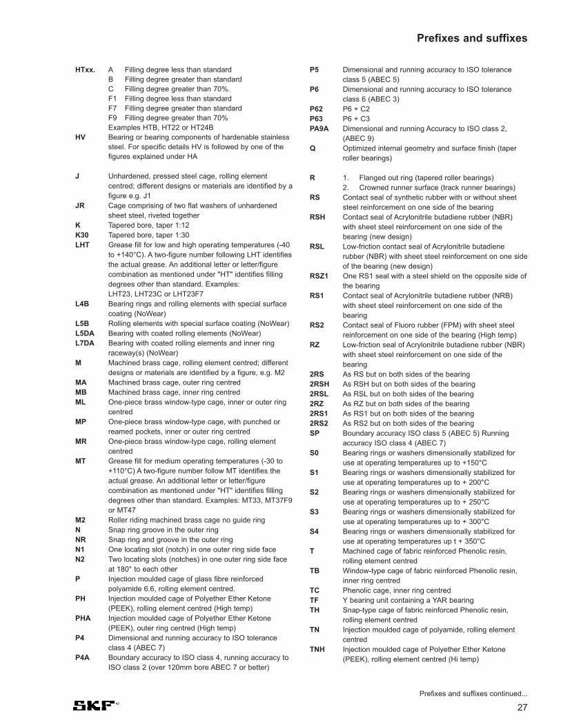
27
HTxx. A Filling degree less than standardB Filling degree greater than standardC Filling degree greater than 70%.F1 Filling degree less than standardF7 Filling degree greater than standardF9 Filling degree greater than 70%Examples HTB, HT22 or HT24B
HV Bearing or bearing components of hardenable stainlesssteel. For specific details HV is followed by one of thefigures explained under HA
J Unhardened, pressed steel cage, rolling elementcentred; different designs or materials are identified by afigure e.g. J1
JR Cage comprising of two flat washers of unhardenedsheet steel, riveted together
K Tapered bore, taper 1:12K30 Tapered bore, taper 1:30LHT Grease fill for low and high operating temperatures (-40
to +140°C). A two-figure number following LHT identifiesthe actual grease. An additional letter or letter/figurecombination as mentioned under "HT" identifies fillingdegrees other than standard. Examples:LHT23, LHT23C or LHT23F7
L4B Bearing rings and rolling elements with special surfacecoating (NoWear)
L5B Rolling elements with special surface coating (NoWear)L5DA Bearing with coated rolling elements (NoWear)L7DA Bearing with coated rolling elements and inner ring
raceway(s) (NoWear)M Machined brass cage, rolling element centred; different
designs or materials are identified by a figure, e.g. M2MA Machined brass cage, outer ring centredMB Machined brass cage, inner ring centredML One-piece brass window-type cage, inner or outer ring
centredMP One-piece brass window-type cage, with punched or
reamed pockets, inner or outer ring centredMR One-piece brass window-type cage, rolling element
centredMT Grease fill for medium operating temperatures (-30 to
+110°C) A two-figure number follow MT identifies theactual grease. An additional letter or letter/figurecombination as mentioned under "HT" identifies fillingdegrees other than standard. Examples: MT33, MT37F9or MT47
M2 Roller riding machined brass cage no guide ringN Snap ring groove in the outer ringNR Snap ring and groove in the outer ringN1 One locating slot (notch) in one outer ring side faceN2 Two locating slots (notches) in one outer ring side face
at 180° to each otherP Injection moulded cage of glass fibre reinforced
polyamide 6.6, rolling element centred.PH Injection moulded cage of Polyether Ether Ketone
(PEEK), rolling element centred (High temp)PHA Injection moulded cage of Polyether Ether Ketone
(PEEK), outer ring centred (High temp)P4 Dimensional and running accuracy to ISO tolerance
class 4 (ABEC 7)P4A Boundary accuracy to ISO class 4, running accuracy to
ISO class 2 (over 120mm bore ABEC 7 or better)
P5 Dimensional and running accuracy to ISO toleranceclass 5 (ABEC 5)
P6 Dimensional and running accuracy to ISO toleranceclass 6 (ABEC 3)
P62 P6 + C2P63 P6 + C3PA9A Dimensional and running Accuracy to ISO class 2,
(ABEC 9)Q Optimized internal geometry and surface finish (taper
roller bearings)
R 1. Flanged out ring (tapered roller bearings)2. Crowned runner surface (track runner bearings)
RS Contact seal of synthetic rubber with or without sheetsteel reinforcement on one side of the bearing
RSH Contact seal of Acrylonitrile butadiene rubber (NBR)with sheet steel reinforcement on one side of thebearing (new design)
RSL Low-friction contact seal of Acrylonitrile butadienerubber (NBR) with sheet steel reinforcement on one sideof the bearing (new design)
RSZ1 One RS1 seal with a steel shield on the opposite side ofthe bearing
RS1 Contact seal of Acrylonitrile butadiene rubber (NRB)with sheet steel reinforcement on one side of thebearing
RS2 Contact seal of Fluoro rubber (FPM) with sheet steelreinforcement on one side of the bearing (High temp)
RZ Low-friction seal of Acrylonitrile butadiene rubber (NBR)with sheet steel reinforcement on one side of thebearing
2RS As RS but on both sides of the bearing2RSH As RSH but on both sides of the bearing2RSL As RSL but on both sides of the bearing2RZ As RZ but on both sides of the bearing2RS1 As RS1 but on both sides of the bearing2RS2 As RS2 but on both sides of the bearingSP Boundary accuracy ISO class 5 (ABEC 5) Running
accuracy ISO class 4 (ABEC 7)S0 Bearing rings or washers dimensionally stabilized for
use at operating temperatures up to +150°CS1 Bearing rings or washers dimensionally stabilized for
use at operating temperatures up to + 200°CS2 Bearing rings or washers dimensionally stabilized for
use at operating temperatures up to + 250°CS3 Bearing rings or washers dimensionally stabilized for
use at operating temperatures up to + 300°CS4 Bearing rings or washers dimensionally stabilized for
use at operating temperatures up t + 350°CT Machined cage of fabric reinforced Phenolic resin,
rolling element centredTB Window-type cage of fabric reinforced Phenolic resin,
inner ring centredTC Phenolic cage, inner ring centredTF Y bearing unit containing a YAR bearingTH Snap-type cage of fabric reinforced Phenolic resin,
rolling element centredTN Injection moulded cage of polyamide, rolling element
centredTNH Injection moulded cage of Polyether Ether Ketone
(PEEK), rolling element centred (Hi temp)
Prefixes and suffixes
Prefixes and suffixes continued...

28
TN9 Injection moulded cage of glass fibre reinforcedpolyamide 6.6 rolling element centred
U U combined with a one-figure number identifies a taperroller bearing cone or cup, with reduced width toleranceExamples:U2: Width tolerance +0.05/0 mmU4: Width tolerance +0.10/0 mm
UP Boundary accuracy ISO class 4 (ABEC 7) Runningaccuracy ISO class 2 (ABEC 9)
V Full complement bearing (without cage)V… V combined with a second letter identifies a variant
group and followed by a three or four-figure numberdenotes variants not covered by "standard" designationsuffixes. Examples:VA Application oriented variantsVB Boundary dimension deviationsVE External or internal deviationsVL CoatingsVQ QualityVS Clearance and preloadVT LubricationVU Miscellaneous applications
VA201 Bearing for high-temperature applications (e.g. kilntrucks) Good up to +250°C Lubricating paste and 100rpm
VA208 Bearing for high-temperature applications, good to350°C (Graphite segment cage) and 100 rpm
VA228 Bearing for high-temperature applications, good to350°C (Graphite cage) and 100 rpm
VA301 Bearing for traction motorsVA305 VA301 + special inspection routinesVA3091 VA301 + VL0241VA405 Bearing for vibratory applications VA406 Bearing for vibratory applications with special PTFE
bore coatingVE240 CARB bearing modified for greater axial displacementVE226 VX110, but with only three lubricating holesVE447 Shaft washer with three equally spaced threaded holes
in one side face to accommodate hoisting tackleVE552 Outer ring with three equally spaced threaded holes in
one side face to accommodate hoisting tackle
VE553 Outer ring with three equally spaced threaded holes inboth side faces to accommodate hoisting tackle
VG114 Surface hardened pressed steel cageVH Full compliment cylindrical roller bearing with self-
retaining roller setVL0241 Aluminum oxide coated outside surface of outer ring for
electrical resistance up to 1000 V DCVQ015 Inner ring with crowned racewayVQ424 Running accuracy better than C08VT143 Grease fill with an extreme pressure greaseVX110 Spherical roller bearing with lubrication groove and six
lubrication holes on inner ringW Without annular groove and lubrication holes in outer ringWT Grease fill for low as well as high operating
temperatures (-40 to +160°C). Greases, which differfrom the selected standard grease for this temperaturerange are identified as explained under "HT" Examples:WT or WTF1
W20 Three lubrication holes in the outer ring (No groove)W22 Reduced tolerance on the outer ringW26 Six lubrication holes in the inner ringW31 Inspected to special quality control requirementsW33 Annular groove and three lubrication holes in the outer ringW4 High point of eccentricity marked on inner ring or sleeveW502 Combination of W22 and W33W507 Combination of W4, W31 & W33W509 Combination of W26, W31 & W33 W513 W26 + W33W525 Combination of W31 and W77W64 Solid Oil fillW77 Plugged W33 lubrication holesX 1. Boundary dimensions altered to conform to ISO
standards2. Cylindrical runner surface (track runner bearing)
Y Pressed brass cage, rolling element centred: differentdesigns or materials are identified by a figure followingthe Y, e.g. Y1
Z Shield of pressed sheet steel on one side of the bearing2Z Shields of pressed sheet steel on both sides of the bearing
Prefixes and suffixes, Temperature conversions

29
W 6200-2Z JNR/C3 HC5 GJN
1 4 7
Deep Groove Ball Bearings
3 5
1. Prefix
R MRC inch seriesW Stainless
2. Seals Shields
FF MRC shield designation SKF ZMetal backed one side ofbearing (also SKF 2Z)
RS2 As RS1 but of Fluorocarbonrubber for higher temperatures(also 2RS2)
RSL As RZ, new design, (also 2RSL)
RSH As RS1 new design, (Also 2RSH) for bearings of 60, 62 and63 series up to 52mm o/d.
RZ Metal backed non-contact sealon one side (Also 2RZ)
Z Metal plateZZ MRC seal designation (SKF 2RS1)2Z Steel plate on 2 sides
3. Cage Design
J Pressed steel cage, rollingelement guided
JEM Steel cage (J), quiet running, C3clearance (not marked onbearing)**
M Machined brass cage, rollingelement guided
MA Machined brass cage, outerring guided
TC Phenolic cage, inner ring guided
TN Polyamide cage
TN9 Fibreglass reinforced Polyamide
Y Pressed Brass cage, ballguided
4. Modification
C MRC designation for Cartridgetype bearing
N Snap ring groove
NR Snap ring & groove
N1,N2 1 or 2 locating notches
S MRC Conrad type
VL0241Electrical insulation of outer ring
VL2071Electrical insulation of inner ring
5. Clearance/Tolerances
C1 Clearance < C2
C2 Clearance < Normal
C0,CN Normal not shown
C3 Clearance > C0 or CN
C4 Clearance > C3
C78 P5 or ABEC 5 toleranceC782 C78 + C2C783 C78 + C3
P5 Tolerance to IS0 class 5 orABEC 5
** If sealed, use GJN grease
6. Special offerings
HC4 Full Ceramic bearingHC5 Ceramic ball setHYB MRC hybrid bearing
VA201 Special specification for kiln trucks
VA 208 Graphite segment cage for hi- temp applications
VA 228 Graphite cage for hi-tempapplications
7. Lubrication
GJN Di-urea, Hi-temp.115 cSt @40°C, range -40°C to + 150°C
GMB Lithium, Medium temp.120 cSt@ 40°C, -30°C to + 110°C
HT 51 Polyurea hi-temp, 110 cSt @40°C, -30°C to + 140°C
LHT 23 Lithium,Wide range, 26 cSt @40°C, -50°C to + 140°C
LHT 30 Lithium, Wide range, 74 cSt at40°C, -40°C to +180°C
LHT 64 Clay, Wide range,13 cSt @40°C, -73°C to + 149°C
MT33* Lithium, Medium temp. 74 cSt@ 40°C, -30°C to + 120°C
MT47* Lithium, Medium temp. 70 cSt@ 40°C, -30°C to + 110°C
W64 Solid oil, various types available depending on the temperature range.
* See page 31 (top)
2 6

Boundary Dimensions In accordance with ISO 15:1998
Tolerances <52mm OD ABEC 5 (ISO P5)52mm <110 mm ABEC 3 (ISO P6)>110 mm OD ABEC 1 (Normal)
Heat Stabilization 257°F (125°C)Operating temperature -40°C to + 100°C or 120°C for short periods
Misalignment 2 minutes of arc
Cage Material Steel (J generally not shown)Standard Optional Machined brass (M, MA)
Polyamide (TN9)
Axial load - max 0.5xC0 for 6200, 6300 and 6400 series0.25xC0 for 61800, 61900 and 6000 series
Seals and Shields 2RS1 - Nitrile rubber seals2RS2 - Fluorocarbon seals (high temp)2RZ - Nitrile rubber seals non-contact2RSL - Nitrile rubber seals non-contact,
new design2RSH - Nitrile rubber seals, new design2Z - Metal shields
30
Technical Features
Single Row Deep Groove Ball Bearing(data tables on page 34)
Single Row Deep Groove Ball Bearing
Max Type(data tables on page 58)
Deep groove ball bearings

Outer ring Groove Groove Groove Fillet Ring Ring section Ring EndO.D. dia. location width radius thickness height gap cover
max. max. min. max. max. max.D D3 C2 b f0 f h g Db
mm in mm in mm in mm in mm in mm in mm in mm in mm in
40 1.5748 38.10 1.500 2.06 0.081 1.35 0.053 0.4 0.016 1.12 0.044 3.25 0.128 3 0.12 45 1.8
47 1.8504 44.60 1.756 2.46 0.097 1.35 0.053 0.4 0.016 1.12 0.044 4.04 0.159 4 0.15 53 2.1
52 2.0472 49.73 1.958 2.46 0.097 1.35 0.053 0.4 0.016 1.12 0.044 4.04 0.159 4 0.15 58 2.3
62 2.4409 59.61 2.347 3.28 0.129 1.90 0.075 0.6 0.024 1.70 0.067 4.04 0.159 4 0.15 68 2.7
72 2.8346 68.81 2.709 3.28 0.129 1.90 0.075 0.6 0.024 1.70 0.067 4.85 0.191 5 0.19 80 3.1
80 3.1496 76.81 3.024 3.28 0.129 1.90 0.075 0.6 0.024 1.70 0.067 4.85 0.191 5 0.19 88 3.5
85 3.3464 81.81 3.221 3.28 0.129 1.90 0.075 0.6 0.024 1.70 0.067 4.85 0.191 5 0.19 93 3.7
90 3.5400 86.79 3.417 3.28 0.129 2.70 0.106 0.6 0.024 2.46 0.097 4.85 0.191 5 0.19 98 3.9
100 3.9370 96.80 3.811 3.28 0.129 2.70 0.106 0.6 0.024 2.46 0.097 4.85 0.191 5 0.19 108 4.3
110 4.3307 106.81 4.205 3.28 0.129 2.70 0.106 0.6 0.024 2.46 0.097 4.85 0.191 5 0.19 118 4.6
120 4.7244 115.21 4.536 4.06 0.160 3.10 0.122 0.6 0.024 2.82 0.111 7.21 0.284 7 0.28 131 5.2
125 4.9210 120.22 4.733 4.06 0.160 3.10 0.122 0.6 0.024 2.82 0.111 7.21 0.284 7 0.28 136 5.4
130 5.1181 125.22 4.930 4.06 0.160 3.10 0.122 0.6 0.024 2.82 0.111 7.21 0.284 7 0.28 141 5.6
140 5.5118 135.23 5.324 4.90 0.193 3.10 0.122 0.6 0.024 2.82 0.111 7.21 0.284 7 0.28 151 5.9
150 5.9055 145.24 5.718 4.90 0.193 3.10 0.122 0.6 0.024 2.82 0.111 7.21 0.284 7 0.28 161 6.3
160 6.2992 155.22 6.111 4.90 0.193 3.10 0.122 0.6 0.024 2.82 0.111 7.21 0.284 7 0.28 171 6.7
170 6.6929 163.65 6.443 5.69 0.224 3.50 0.138 0.6 0.024 3.10 0.122 9.60 0.378 10 0.39 184 7.2
180 7.0866 173.66 6.837 5.69 0.224 3.50 0.138 0.6 0.024 3.10 0.122 9.60 0.378 10 0.39 194 7.6
190 7.4803 183.64 7.230 5.69 0.224 3.50 0.138 0.6 0.024 3.10 0.122 9.60 0.378 10 0.39 204 8.0
200 7.8740 193.65 7.624 5.69 0.224 3.50 0.138 0.6 0.024 3.10 0.122 9.60 0.378 10 0.39 214 8.4
31
Snap ring and groove dimensions - ball bearings
Deep groove ball bearings
Snap Ring and Snap Ring Groove Dimensions
Deep Groove Ball BearingStandard Greases(The grease is not shown in the part number)
On bearings W618__ and W619__under 30mm on the O/D LT10 (EssoBeacon 325)
All other deep groove ball bearings upto 62mm on the O/D MT47 (ShellAlvania RLQ2)
All deep groove ball bearings over 62mmon the O/D MT33 (Shell Alvania R3)
MRC uses Esso Polyrex EM.
All other grease types should beshown with their appropriatesuffixes.

Bore Radial internal clearancediameterd C2 Normal C3 C4 C5
over incl. min max min max min max min max min max min max min max min max min max min maxmm µm in µm in µm in µm in µm in
2.5 10 0 7 0.0000 0.0003 2 13 0.0001 0.0005 8 23 0.0003 0.0009 14 29 0.0006 0.0011 20 37 0.0008 0.001510 18 0 9 0.0000 0.0004 3 18 0.0001 0.0007 11 25 0.0004 0.0010 18 33 0.0007 0.0013 25 45 0.0010 0.001818 24 0 10 0.0000 0.0004 5 20 0.0002 0.0008 13 28 0.0005 0.0011 20 36 0.0008 0.0014 28 48 0.0011 0.0019
24 30 1 11 0.0000 0.0004 5 20 0.0002 0.0008 13 28 0.0005 0.0011 23 41 0.0009 0.0016 30 53 0.0012 0.002130 40 1 11 0.0000 0.0004 6 20 0.0002 0.0008 15 33 0.0006 0.0013 28 46 0.0011 0.0018 40 64 0.0016 0.002540 50 1 11 0.0000 0.0004 6 23 0.0002 0.0009 18 36 0.0007 0.0014 30 51 0.0012 0.0020 45 73 0.0018 0.0029
50 65 1 15 0.0000 0.0006 8 28 0.0003 0.0011 23 43 0.0009 0.0017 38 61 0.0015 0.0024 55 90 0.0022 0.003565 80 1 15 0.0000 0.0006 10 30 0.0004 0.0012 25 51 0.0010 0.0020 46 71 0.0018 0.0028 65 105 0.0026 0.004180 100 1 18 0.0000 0.0007 12 36 0.0005 0.0014 30 58 0.0012 0.0023 53 84 0.0021 0.0033 75 120 0.0030 0.0047
100 120 2 20 0.0001 0.0008 15 41 0.0006 0.0016 36 66 0.0014 0.0026 61 97 0.0024 0.0038 90 140 0.0035 0.0055120 140 2 23 0.0001 0.0009 18 48 0.0007 0.0019 41 81 0.0016 0.0032 71 114 0.0028 0.0045 105 160 0.0041 0.0063140 160 2 23 0.0001 0.0009 18 53 0.0007 0.0021 46 91 0.0018 0.0036 81 130 0.0032 0.0051 120 180 0.0047 0.0071
160 180 2 25 0.0001 0.0010 20 61 0.0008 0.0024 53 102 0.0021 0.0040 91 147 0.0036 0.0058 135 200 0.0053 0.0079180 200 2 30 0.0001 0.0012 25 71 0.0010 0.0028 63 117 0.0025 0.0046 107 163 0.0042 0.0064 150 230 0.0059 0.0091200 225 4 32 0.0002 0.0013 28 82 0.0011 0.0032 73 132 0.0029 0.0052 120 187 0.0047 0.0074 175 255 0.0069 0.0100
225 250 4 36 0.0002 0.0014 31 92 0.0012 0.0036 87 152 0.0034 0.0060 140 217 0.0055 0.0085 205 290 0.0081 0.0114250 280 4 39 0.0002 0.0015 36 97 0.0014 0.0038 97 162 0.0038 0.0064 152 237 0.0060 0.0093 255 320 0.0100 0.0126280 315 8 45 0.0003 0.0018 42 110 0.0017 0.0043 110 180 0.0043 0.0071 175 260 0.0069 0.0102 260 360 0.0102 0.0142
315 355 8 50 0.0003 0.0020 50 120 0.0020 0.0047 120 200 0.0047 0.0079 200 290 0.0079 0.0114 290 405 0.0114 0.0159355 400 8 60 0.0003 0.0024 60 140 0.0024 0.0055 140 230 0.0055 0.0091 230 330 0.0091 0.0130 330 460 0.0130 0.0181400 450 10 70 0.0004 0.0028 70 160 0.0028 0.0063 160 260 0.0063 0.0102 260 370 0.0102 0.0146 370 520 0.0146 0.0205
450 500 10 80 0.0004 0.0031 80 180 0.0031 0.0071 180 290 0.0071 0.0114 290 410 0.0114 0.0161 410 570 0.0161 0.0224500 560 20 90 0.0008 0.0035 90 200 0.0035 0.0079 200 320 0.0079 0.0126 320 460 0.0126 0.0181 460 630 0.0181 0.0248560 630 20 100 0.0008 0.0039 100 220 0.0039 0.0087 220 350 0.0087 0.0138 350 510 0.0138 0.0201 510 700 0.0201 0.0276
630 710 30 120 0.0012 0.0047 120 250 0.0047 0.0098 250 390 0.0098 0.0154 390 560 0.0154 0.0220 560 780 0.0220 0.0307710 800 30 130 0.0012 0.0051 130 280 0.0051 0.0110 280 440 0.011 0.0173 440 620 0.0173 0.0244 620 860 0.0244 0.0339800 900 30 150 0.0012 0.0059 150 310 0.0059 0.0122 310 490 0.0122 0.0193 490 690 0.0193 0.0272 690 960 0.0272 0.0378
900 1 000 40 160 0.0016 0.0063 160 340 0.0063 0.0134 340 540 0.0134 0.0213 540 760 0.0213 0.0299 760 1040 0.0299 0.04091 000 1 120 40 170 0.0016 0.0067 170 370 0.0067 0.0146 370 590 0.0146 0.0232 590 840 0.0232 0.0331 840 1120 0.0331 0.0441
Table 1 Radial internal clearance of deep groove ball bearings
32
Masses The masses given in the tables are for thebasic design of the bearing. The mass ofbearings with shield(s), seal(s) or snap ringgroove differs only slightly from that of thebasic bearing.
Lubrication Bearings with shields or seals at both sidesare supplied as standard filled with agrease which has good rust inhibiting prop-erties and which is suitable for operatingtemperatures between -22 and +230°F (-30to +110°C). The bearings are lubricated forlife and are maintenance free. Theyshould on no account be heated to tem-peratures above 250°F (120°C), norshould they be washed. By special order,bearings with shields or seals can be sup-plied with other greases, e.g. for a tempera-ture range of -40 to +300°F (-40 to +150°C).
The quantity of grease supplied is appropri-ate to the size of the bearing and normallyfills between 25 and 35% of the free spacein the bearing. Open bearings are suppliedwith a rust preservative that is compatiblewith most standard greases and should notbe removed prior to mounting or lubricating.
* Other greases are available on request.
InternalClearance Radial internal clearance (table 1)SKF single row deep groove ball bearingsare produced with Normal radial internalclearance (CN or C0 not marked onbearing) as standard. Radial clearanceselection is based on factors such as highspeed, operating temperature, shaft fits andaxial movement limitations. The availabilityof bearings with clearances other thanNormal should be checked before ordering.The suffix JEM indicates an internalclearance greater than Normal (C3). Manyof the bearings, particularly the smallersizes, are also available with radial internalclearance, which is greater than or lessthan Normal (C3, C2 respectively).
The values of the clearance limits for singlerow deep groove ball bearings are shown intable 1. They conform to ISO 5753-1991(ABMA standard 20-1996) for the sizerange covered by this standard. The valuesapply to unmounted bearings under zeromeasuring load.
Deep groove ball bearings
33
Deep groove ball bearings

623
618/4619/4604624634
618/5619/5
*625*635
618/6619/6
*626
618/7619/7
*607*627
618/8619/8
*608*628
618/9619/9
*609*629
6180061900
*600016100
*6200*6300
6180161901
*600116101
*6201*6301
0.394 0.157 0.54 0.18 0.007 130 000 80 000 0.0015
0.354 0.098 0.54 0.18 0.007 140 000 85 000 0.00070.433 0.157 0.715 0.232 0.01 130 000 80 000 0.00170.472 0.157 0.806 0.28 0.012 120 000 75 000 0.00210.512 0.197 0.936 0.29 0.012 110 000 67 000 0.00310.630 0.197 1.11 0.38 0.016 95 000 60 000 0.0054
0.433 0.118 0.637 0.255 0.011 120 000 75 000 0.00120.512 0.157 0.884 0.34 0.014 110 000 67 000 0.00250.630 0.197 1.14 0.38 0.016 95 000 60 000 0.0050.748 0.236 2.34 0.95 0.04 80 000 50 000 0.009
0.512 0.138 0.884 0.345 0.015 110 000 67 000 0.0020.591 0.197 1.24 0.475 0.02 100 000 63 000 0.00390.748 0.236 2.34 0.95 0.04 80 000 50 000 0.0084
0.551 0.138 0.956 0.4 0.017 100 000 63 000 0.00220.669 0.197 1.48 0.56 0.024 90 000 56 000 0.00490.748 0.236 2.34 0.95 0.04 85 000 53 000 0.00750.866 0.276 3.45 1.37 0.057 70 000 45 000 0.013
0.630 0.157 1.33 0.57 0.024 90 000 56 000 0.0030.748 0.236 1.9 0.735 0.031 80 000 50 000 0.00710.866 0.276 3.45 1.37 0.057 75 000 48 000 0.0120.945 0.315 3.9 1.66 0.071 63 000 40 000 0.017
0.669 0.157 1.43 0.64 0.027 85 000 53 000 0.00340.787 0.236 2.08 0.865 0.036 80 000 48 000 0.00760.945 0.276 3.9 1.66 0.071 70 000 43 000 0.0141.024 0.315 4.75 1.96 0.083 60 000 38 000 0.02
0.748 0.197 1.38 0.585 0.025 80 000 48 000 0.00550.866 0.236 2.08 0.85 0.036 75 000 45 000 0.011.024 0.315 4.75 1.96 0.083 67 000 40 000 0.0191.102 0.315 4.62 1.96 0.083 63 000 40 000 0.0221.181 0.354 5.4 2.36 0.1 56 000 34 000 0.0321.378 0.433 8.52 3.4 0.143 50 000 32 000 0.053
0.827 0.197 1.43 0.67 0.028 70 000 43 000 0.00630.945 0.236 2.25 0.98 0.043 67 000 40 000 0.0111.102 0.315 5.4 2.36 0.1 60 000 38 000 0.0221.181 0.315 5.07 2.36 0.1 56 000 34 000 0.0231.260 0.394 7.28 3.1 0.132 50 000 32 000 0.0371.457 0.472 10.1 4.15 0.176 45 000 28 000 0.06
0.118
0.157
0.197
0.236
0.276
0.315
0.354
0.394
0.472
10 4
9 2.511 412 413 516 5
11 313 416 519 6
13 3.515 519 6
14 3.517 519 622 7
16 419 622 724 8
17 420 624 726 8
19 522 626 828 830 935 11
21 524 628 830 832 1037 12
34
Single row deep groove ball bearingsd 3 - 12 mmd 0.118 - 0.472 in
3
4
5
6
7
8
9
10
12
Principal dimensions Basic load ratings Fatigue Speed ratings Mass Designationdynamic static load Reference Limiting
limit speed speedd D B d D B C C0 Pu
mm in kN kN r/min kg –
D
B
d
* SKF Explorer bearing

6180261902
*16002*6002*6202*6302
6180361903
*16003*6003
98203*62036203 ETN9
*63036403
6180461904
*1600498204 Y
*6004
*62046204 ETN9
*63046304 ETN96404
62/2263/22
6180561905
*16005*6005
98205*62056205 ETN9
*63056305 ETN96405
0.945 0.197 1.56 0.8 0.034 60 000 38 000 0.00741.102 0.276 4.36 2.24 0.095 56 000 34 000 0.0161.260 0.315 5.85 2.85 0.12 50 000 32 000 0.0251.260 0.354 5.85 2.85 0.12 50 000 32 000 0.031.378 0.433 8.06 3.75 0.16 43 000 28 000 0.0451.654 0.512 11.9 5.4 0.228 38 000 24 000 0.082
1.024 0.197 1.68 0.93 0.039 56 000 34 000 0.00821.181 0.276 4.62 2.55 0.108 50 000 32 000 0.0181.378 0.315 6.37 3.25 0.137 45 000 28 000 0.0321.378 0.394 6.37 3.25 0.137 45 000 28 000 0.039
1.575 0.354 9.56 4.75 0.2 38 000 24 000 0.0481.575 0.472 9.95 4.75 0.2 38 000 24 000 0.0651.575 0.472 11.4 5.4 0.228 38 000 24 000 0.0641.850 0.551 14.3 6.55 0.275 34 000 22 000 0.122.441 0.669 22.9 10.8 0.455 28 000 18 000 0.27
1.260 0.276 4.03 2.32 0.104 45 000 28 000 0.0181.457 0.354 6.37 3.65 0.156 43 000 26 000 0.0381.654 0.315 7.28 4.05 0.173 38 000 24 000 0.051.654 0.354 7.93 4.5 0.19 38 000 24 000 0.0511.654 0.472 9.95 5 0.212 38 000 24 000 0.069
1.850 0.551 13.5 6.55 0.28 32 000 20 000 0.111.850 0.551 15.6 7.65 0.325 32 000 20 000 0.0962.047 0.591 16.8 7.8 0.335 30 000 19 000 0.142.047 0.591 18.2 9 0.38 30 000 19 000 0.142.835 0.748 30.7 15 0.64 24 000 15 000 0.4
1.969 0.551 14 7.65 0.325 30 000 19 000 0.122.205 0.630 18.6 9.3 0.39 28 000 18 000 0.18
1.457 0.276 4.36 2.6 0.125 38 000 24 000 0.0221.654 0.354 7.02 4.3 0.193 36 000 22 000 0.0451.850 0.315 8.06 4.75 0.212 32 000 20 000 0.061.850 0.472 11.9 6.55 0.275 32 000 20 000 0.08
2.047 0.354 10.6 6.55 0.28 28 000 18 000 0.0782.047 0.591 14.8 7.8 0.335 28 000 18 000 0.132.047 0.591 17.8 9.8 0.4 28 000 18 000 0.12
2.441 0.669 23.4 11.6 0.49 24 000 16 000 0.232.441 0.669 26 13.4 0.57 24 000 16 000 0.213.150 0.827 35.8 19.3 0.82 20 000 13 000 0.53
0.591
0.669
0.787
0.866
0.984
24 528 732 832 935 1142 13
26 530 735 835 10
40 940 1240 1247 1462 17
32 737 942 842 942 12
47 1447 1452 1552 1572 19
50 1456 16
37 742 947 847 12
52 952 1552 15
62 1762 1780 21
15
17
20
22
25
35
Principal dimensions Basic load ratings Fatigue Speed ratings Mass Designationdynamic static load Reference Limiting
limit speed speedd D B d D B C C0 Pu
mm in kN kN r/min kg –
Single row deep groove ball bearingsd 15 - 25 mm
d 0.591 - 0.984 in
* SKF Explorer bearing

62/2863/28
6180661906
*16006*6006
98206*62066206 ETN9
*63066306 ETN96406
6180761907
*16007*6007
*62076207 ETN9
*63076407
6180861908
*16008*6008*62086208 ETN9
*63086408
6180961909
*16009*6009*6209*63096409
6181061910
*16010*6010*6210*63106410
2.283 0.630 16.8 9.5 0.405 26 000 16 000 0.182.677 0.709 25.1 13.7 0.585 22 000 14 000 0.29
1.654 0.276 4.49 2.9 0.146 32 000 20 000 0.0271.850 0.354 7.28 4.55 0.212 30 000 19 000 0.0512.165 0.354 11.9 7.35 0.31 28 000 17 000 0.0852.165 0.512 13.8 8.3 0.355 28 000 17 000 0.12
2.441 0.394 15.9 10.2 0.44 22 000 14 000 0.122.441 0.630 20.3 11.2 0.48 24 000 15 000 0.22.441 0.630 23.4 12.9 0.54 24 000 15 000 0.192.835 0.748 29.6 16 0.67 20 000 13 000 0.352.835 0.748 32.5 17.3 0.74 22 000 14 000 0.333.543 0.906 43.6 23.6 1 18 000 11 000 0.74
1.850 0.276 4.75 3.2 0.17 28 000 18 000 0.032.165 0.394 9.56 6.8 0.29 26 000 16 000 0.082.441 0.354 13 8.15 0.38 24 000 15 000 0.112.441 0.551 16.8 10.2 0.44 24 000 15 000 0.16
2.835 0.669 27 15.3 0.66 20 000 13 000 0.292.835 0.669 31.2 17.6 0.75 20 000 13 000 0.273.150 0.827 35.1 19 0.82 19 000 12 000 0.463.937 0.984 55.3 31 1.29 16 000 10 000 0.95
2.047 0.276 4.94 3.45 0.19 26 000 16 000 0.0342.441 0.472 13.8 10 0.43 24 000 14 000 0.122.677 0.354 13.8 9.15 0.44 22 000 14 000 0.132.677 0.591 17.8 11.6 0.49 22 000 14 000 0.193.150 0.709 32.5 19 0.8 18 000 11 000 0.373.150 0.709 35.8 20.8 0.88 18 000 11 000 0.343.543 0.906 42.3 24 1.02 17 000 11 000 0.634.331 1.063 63.7 36.5 1.53 14 000 9 000 1.25
2.283 0.276 6.63 6.1 0.26 22 000 14 000 0.042.677 0.472 14 10.8 0.47 20 000 13 000 0.142.953 0.394 16.5 10.8 0.52 20 000 12 000 0.172.953 0.630 22.1 14.6 0.64 20 000 12 000 0.253.346 0.748 35.1 21.6 0.92 17 000 11 000 0.413.937 0.984 55.3 31.5 1.34 15 000 9 500 0.834.724 1.142 76.1 45 1.9 13 000 8 500 1.55
2.559 0.276 6.76 6.8 0.285 20 000 13 000 0.0522.835 0.472 14.6 11.8 0.5 19 000 12 000 0.143.150 0.394 16.8 11.4 0.56 18 000 11 000 0.183.150 0.630 22.9 16 0.71 18 000 11 000 0.263.543 0.787 37.1 23.2 0.98 15 000 10 000 0.464.331 1.063 65 38 1.6 13 000 8 500 1.055.118 1.220 87.1 52 2.2 12 000 7 500 1.9
1.102
1.181
1.378
1.575
1.772
1.969
58 1668 18
42 747 955 955 13
62 1062 1662 1672 1972 1990 23
47 755 1062 962 14
72 1772 1780 21100 25
52 762 1268 968 1580 1880 1890 23110 27
58 768 1275 1075 1685 19100 25120 29
65 772 1280 1080 1690 20110 27130 31
36
Single row deep groove ball bearingsd 28 - 50 mmd 1.102 - 1.969 in
28
30
35
40
45
50
Principal dimensions Basic load ratings Fatigue Speed ratings Mass Designationdynamic static load Reference Limiting
limit speed speedd D B d D B C C0 Pu
mm in kN kN r/min kg –
D
B
d
* SKF Explorer bearing

37
Principal dimensions Basic load ratings Fatigue Speed ratings Mass Designationdynamic static load Reference Limiting
limit speed speedd D B d D B C C0 Pu
mm in kN kN r/min kg –
Single row deep groove ball bearingsd 55 - 80 mm
d 2.165 - 3.150 in
6181161911
*16011*6011*6211*63116411
6181261912
*16012*6012*6212*63126412
6181361913
*16013*6013*6213*63136413
6181461914
*16014*6014*6214*63146414
618156191516115
*16015*6015*6215*63156415
6181661916
*16016*6016*6216*63166416
2.835 0.354 9.04 8.8 0.38 19 000 12 000 0.0833.150 0.512 16.5 14 0.6 17 000 11 000 0.193.543 0.433 20.3 14 0.7 16 000 10 000 0.263.543 0.709 29.6 21.2 0.9 16 000 10 000 0.393.937 0.827 46.2 29 1.25 14 000 9 000 0.614.724 1.142 74.1 45 1.9 12 000 8 000 1.355.512 1.299 99.5 62 2.6 11 000 7 000 2.3
3.071 0.394 11.9 11.4 0.49 17 000 11 000 0.113.346 0.512 16.5 14.3 0.6 16 000 10 000 0.23.740 0.433 20.8 15 0.74 15 000 9 500 0.283.740 0.709 30.7 23.2 0.98 15 000 9 500 0.424.331 0.866 55.3 36 1.53 13 000 8 000 0.785.118 1.220 85.2 52 2.2 11 000 7 000 1.75.906 1.378 108 69.5 2.9 10 000 6 300 2.75
3.346 0.394 12.4 12.7 0.54 16 000 10 000 0.133.543 0.512 17.4 16 0.68 15 000 9 500 0.223.937 0.433 22.5 16.6 0.83 14 000 9 000 0.33.937 0.709 31.9 25 1.06 14 000 9 000 0.444.724 0.906 58.5 40.5 1.73 12 000 7 500 0.995.512 1.299 97.5 60 2.5 10 000 6 700 2.16.299 1.457 119 78 3.15 9 500 6 000 3.3
3.543 0.394 12.4 13.2 0.56 15 000 9 000 0.143.937 0.630 23.8 21.2 0.9 14 000 8 500 0.354.331 0.512 29.1 25 1.06 13 000 8 000 0.434.331 0.787 39.7 31 1.32 13 000 8 000 0.64.921 0.945 63.7 45 1.9 11 000 7 000 1.055.906 1.378 111 68 2.75 9 500 6 300 2.57.087 1.654 143 104 3.9 8 500 5 300 4.85
3.740 0.394 12.7 14.3 0.61 14 000 8 500 0.154.134 0.630 24.2 19.3 0.965 13 000 8 000 0.374.331 0.472 28.6 27 1.14 13 000 8 000 0.384.528 0.512 30.2 27 1.14 12 000 7 500 0.464.528 0.787 41.6 33.5 1.43 12 000 7 500 0.645.118 0.984 68.9 49 2.04 10 000 6 700 1.26.299 1.457 119 76.5 3 9 000 5 600 37.480 1.772 153 114 4.15 8 000 5 000 6.8
3.937 0.394 13 15 0.64 13 000 8 000 0.154.331 0.630 25.1 20.4 1.02 12 000 7 500 0.44.921 0.551 35.1 31.5 1.32 11 000 7 000 0.64.921 0.866 49.4 40 1.66 11 000 7 000 0.855.512 1.024 72.8 55 2.2 9 500 6 000 1.46.693 1.535 130 86.5 3.25 8 500 5 300 3.67.874 1.890 163 125 4.5 7 500 4 800 8
2.165
2.362
2.559
2.756
2.953
3.150
72 980 1390 1190 18100 21120 29140 33
78 1085 1395 1195 18110 22130 31150 35
85 1090 13100 11100 18120 23140 33160 37
90 10100 16110 13110 20125 24150 35180 42
95 10105 16110 12115 13115 20130 25160 37190 45
100 10110 16125 14125 22140 26170 39200 48
55
60
65
70
75
80
* SKF Explorer bearing

6181761917
*16017*6017*6217*63176417
6181861918
*16018*6018*6218*63186418
6181961919
*16019*6019*6219*6319
6182061920
*16020*6020*62206320
6182161921
*16021*6021*62216321
6182261922
*16022*6022*62226322
4.331 0.512 19.5 20.8 0.88 12 000 7 500 0.274.724 0.709 31.9 30 1.25 11 000 7 000 0.555.118 0.551 35.8 33.5 1.37 11 000 6 700 0.635.118 0.866 52 43 1.76 11 000 6 700 0.895.906 1.102 87.1 64 2.5 9 000 5 600 1.87.087 1.614 140 96.5 3.55 8 000 5 000 4.258.268 2.047 174 137 4.75 7 000 4 500 9.5
4.528 0.512 19.5 22 0.915 11 000 7 000 0.284.921 0.709 33.2 31.5 1.23 11 000 6 700 0.595.512 0.630 43.6 39 1.56 10 000 6 300 0.855.512 0.945 60.5 50 1.96 10 000 6 300 1.156.299 1.181 101 73.5 2.8 8 500 5 300 2.157.480 1.693 151 108 3.8 7 500 4 800 4.98.858 2.126 186 150 5 6 700 4 300 11.5
4.724 0.512 19.9 22.8 0.93 11 000 6 700 0.35.118 0.709 33.8 33.5 1.43 10 000 6 300 0.615.709 0.630 44.8 41.5 1.63 9 500 6 000 0.895.709 0.945 63.7 54 2.08 9 500 6 000 1.26.693 1.260 114 81.5 3 8 000 5 000 2.67.874 1.772 159 118 4.15 7 000 4 500 5.65
4.921 0.512 19.9 24 0.95 10 000 6 300 0.315.512 0.787 42.3 41 1.63 9 500 6 000 0.835.906 0.630 46.2 44 1.73 9 500 5 600 0.915.906 0.945 63.7 54 2.04 9 500 5 600 1.257.087 1.339 127 93 3.35 7 500 4 800 3.158.465 1.850 174 140 4.75 6 700 4 300 7
5.118 0.512 20.8 19.6 1 10 000 6 300 0.325.709 0.787 44.2 44 1.7 9 500 5 600 0.876.299 0.709 54 51 1.86 8 500 5 300 1.26.299 1.024 76.1 65.5 2.4 8 500 5 300 1.67.480 1.417 140 104 3.65 7 000 4 500 3.78.858 1.929 182 153 5.1 6 300 4 000 8.25
5.512 0.630 28.1 26 1.25 9 500 5 600 0.65.906 0.787 43.6 45 1.66 9 000 5 600 0.96.693 0.748 60.2 57 2.04 8 000 5 000 1.456.693 1.102 85.2 73.5 2.4 8 000 5 000 1.957.874 1.496 151 118 4 6 700 4 300 4.359.449 1.969 203 180 5.7 6 000 3 800 9.55
3.346
3.543
3.740
3.937
4.134
4.331
110 13120 18130 14130 22150 28180 41210 52
115 13125 18140 16140 24160 30190 43225 54
120 13130 18145 16145 24170 32200 45
125 13140 20150 16150 24180 34215 47
130 13145 20160 18160 26190 36225 49
140 16150 20170 19170 28200 38240 50
38
Single row deep groove ball bearingsd 85 - 110 mmd 3.346 - 4.331 in
85
90
95
100
105
110
Principal dimensions Basic load ratings Fatigue Speed ratings Mass Designationdynamic static load Reference Limiting
limit speed speedd D B d D B C C0 Pu
mm in kN kN r/min kg –
D
B
d
* SKF Explorer bearing

39
Principal dimensions Basic load ratings Fatigue Speed ratings Mass Designationdynamic static load Reference Limiting
limit speed speedd D B d D B C C0 Pu
mm in kN kN r/min kg –
Single row deep groove ball bearingsd 120 - 180 mm
d 4.724 - 7.087 in
6182461924
*16024*602462246324
6182661926
*16026*602662266326 M
6182861928 MA16028602862286328 M
6183061930 MA16030603062306330 M
6183261932 MA16032603262326332 M
6183461934 MA160346034 M6234 M6334 M
6183661936 MA160366036 M6236 M6336 M
5.906 0.630 29.1 28 1.29 8 500 5 300 0.656.496 0.866 55.3 57 2.04 8 000 5 000 1.27.087 0.748 63.7 64 2.2 7 500 4 800 1.67.087 1.102 88.4 80 2.75 7 500 4 800 2.058.465 1.575 146 118 3.9 6 300 4 000 5.1510.236 2.165 208 186 5.7 5 600 3 400 12.5
6.496 0.709 37.7 43 1.6 8 000 4 800 0.937.087 0.945 65 67 2.28 7 500 4 500 1.857.874 0.866 83.2 81.5 2.7 7 000 4 300 2.357.874 1.299 112 100 3.35 7 000 4 300 3.159.055 1.575 156 132 4.15 5 600 3 600 5.811.024 2.283 229 216 6.3 5 000 3 200 17.5
6.890 0.709 39 46.5 1.66 7 500 4 500 0.997.480 0.945 66.3 72 2.36 7 000 5 600 1.78.268 0.866 80.6 86.5 2.8 6 700 4 000 2.58.268 1.299 111 108 3.45 6 700 4 000 3.359.843 1.654 165 150 4.55 5 300 3 400 7.4511.811 2.441 251 245 7.1 4 800 4 300 22
7.480 0.787 48.8 61 1.96 6 700 4 300 1.48.268 1.102 88.4 93 2.9 6 300 5 300 3.058.858 0.945 92.2 98 3.05 6 000 3 800 3.158.858 1.378 125 125 3.9 6 000 3 800 4.810.630 1.772 174 166 4.9 5 000 3 200 9.412.598 2.559 276 285 7.8 4 300 4 000 26
7.874 0.787 49.4 64 2 6 300 4 000 1.458.661 1.102 92.3 98 3.05 6 000 5 000 3.259.449 0.984 99.5 108 3.25 5 600 3 600 3.79.449 1.496 143 143 4.3 5 600 3 600 5.911.417 1.890 186 186 5.3 4 500 3 000 14.513.386 2.677 276 285 7.65 4 000 3 800 29
8.465 0.866 61.8 78 2.4 6 000 3 600 1.99.055 1.102 93.6 106 3.15 5 600 4 800 3.410.236 1.102 119 129 3.75 5 300 3 200 510.236 1.654 168 173 5 5 300 4 300 7.912.205 2.047 212 224 6.1 4 300 3 800 17.514.173 2.835 312 340 8.8 3 800 3 400 34.5
8.858 0.866 62.4 81.5 2.45 5 600 3 400 29.843 1.299 119 134 3.9 5 300 4 300 5.0511.024 1.220 138 146 4.15 4 800 4 000 6.611.024 1.811 190 200 5.6 4 800 4 000 10.512.598 2.047 229 240 6.4 4 000 3 600 18.514.961 2.953 351 405 10.4 3 600 3 200 42.5
4.724
5.118
5.512
5.906
6.299
6.693
7.087
150 16165 22180 19180 28215 40260 55
165 18180 24200 22200 33230 40280 58
175 18190 24210 22210 33250 42300 62
190 20210 28225 24225 35270 45320 65
200 20220 28240 25240 38290 48340 68
215 22230 28260 28260 42310 52360 72
225 22250 33280 31280 46320 52380 75
120
130
140
150
160
170
180
* SKF Explorer bearing

6183861938 MA160386038 M6238 M6338 M
6184061940 MA160406040 M6240 M
6184461944 MA160446044 M6244 M6344 M
6184861948 MA16048 MA6048 M6248 M6348 M
6185261952 MA16052 MA6052 M6252 M
6185661956 MA16056 MA6056 M6256 M
61860 MA61960 MA16060 MA6060 M6260 M
61864 MA61964 MA16064 MA6064 M
9.449 0.945 76.1 98 2.8 5 300 3 200 2.610.236 1.299 117 134 3.8 5 000 4 300 5.2511.417 1.220 148 166 4.55 4 800 3 000 7.911.417 1.811 195 216 5.85 4 800 3 800 1113.386 2.165 255 280 7.35 3 800 3 400 2315.748 3.071 371 430 10.8 3 400 3 000 49
9.843 0.945 76.1 102 2.9 5 000 3 200 2.711.024 1.496 148 166 4.55 4 800 3 800 7.412.205 1.339 168 190 5.1 4 300 2 800 8.8512.205 2.008 216 245 6.4 4 300 3 600 1414.173 2.283 270 310 7.8 3 600 3 200 28
10.630 0.945 78 110 3 4 500 2 800 311.811 1.496 151 180 4.75 4 300 3 600 813.386 1.457 174 204 5.2 4 000 2 400 11.513.386 2.205 247 290 7.35 4 000 3 200 18.515.748 2.559 296 365 8.8 3 200 3 000 3718.110 3.465 410 520 12 3 000 2 600 72.5
11.811 1.102 108 150 3.8 4 000 2 600 4.512.598 1.496 159 200 5.1 4 000 3 200 8.614.173 1.457 178 220 5.3 3 600 3 000 14.514.173 2.205 255 315 7.8 3 600 3 000 19.517.323 2.835 358 465 10.8 3 000 2 600 5119.685 3.740 442 585 12.9 2 600 2 400 92.5
12.598 1.102 111 163 4 3 800 2 400 4.814.173 1.811 212 270 6.55 3 600 3 000 14.515.748 1.732 238 310 7.2 3 200 2 800 21.515.748 2.559 291 375 8.8 3 200 2 800 29.518.898 3.150 390 530 11.8 2 600 2 400 65.5
13.780 1.299 138 200 4.75 3 400 2 200 7.414.961 1.811 216 285 6.7 3 200 2 800 1516.535 1.732 242 335 7.5 3 000 2 600 2316.535 2.559 302 405 9.3 3 000 2 600 3119.685 3.150 423 600 12.9 2 600 2 200 71
14.961 1.496 172 245 5.6 3 200 2 600 10.516.535 2.205 270 375 8.3 3 000 2 400 24.518.110 1.969 286 405 8.8 2 800 2 400 3218.110 2.913 358 500 10.8 2 800 2 400 4421.260 3.346 462 670 13.7 2 400 2 000 88.5
15.748 1.496 172 255 5.7 3 000 2 400 1117.323 2.205 276 400 8.65 2 800 2 400 25.518.898 1.969 281 405 8.65 2 600 2 200 3418.898 2.913 371 540 11.4 2 600 2 200 46
7.480
7.874
8.661
9.449
10.236
11.024
11.811
12.598
240 24260 33290 31290 46340 55400 78
250 24280 38310 34310 51360 58
270 24300 38340 37340 56400 65460 88
300 28320 38360 37360 56440 72500 95
320 28360 46400 44400 65480 80
350 33380 46420 44420 65500 80
380 38420 56460 50460 74540 85
400 38440 56480 50480 74
40
Single row deep groove ball bearingsd 190 - 320 mmd 7.480 - 12.598 in
190
200
220
240
260
280
300
320
Principal dimensions Basic load ratings Fatigue Speed ratings Mass Designationdynamic static load Reference Limiting
limit speed speedd D B d D B C C0 Pu
mm in kN kN r/min kg –
D
B
d

41
Principal dimensions Basic load ratings Fatigue Speed ratings Mass Designationdynamic static load Reference Limiting
limit speed speedd D B d D B C C0 Pu
mm in kN kN r/min kg –
Single row deep groove ball bearingsd 340 - 600 mm
d 13.386 - 23.622 in
61868 MA61968 MA16068 MA6068 M
61872 MA61972 MA16072 MA6072 M
61876 MA61976 MA16076 MA6076 M
61880 MA61980 MA6080 M
61884 MA61984 MA6084 M
61888 MA61988 MA6088 M
61892 MA61992 MA6092 MB
61896 MA61996 MA6096 MB
618/500 MA619/500 MA60/500 N1MAS
618/530 MA619/530 MA60/530 N1MAS
618/560 MA619/560 MA60/560 N1MAS
618/600 MA619/600 MA
16.535 1.496 178 275 6 2 800 2 400 11.518.110 2.205 281 425 9 2 600 2 200 26.520.472 2.244 345 520 10.6 2 400 2 000 4520.472 3.228 423 640 13.2 2 400 2 000 62
17.323 1.496 182 285 6.1 2 600 2 200 1218.898 2.205 291 450 9.15 2 600 2 000 2821.260 2.244 351 550 11 2 400 1 900 4921.260 3.228 462 735 15 2 400 1 900 64.5
18.898 1.811 242 390 8 2 400 2 000 2020.472 2.559 338 540 10.8 2 400 1 900 4022.047 2.244 377 620 12.2 2 200 1 800 5122.047 3.228 462 750 14.6 2 200 1 800 67.5
19.685 1.811 247 405 8.15 2 400 1 900 20.521.260 2.559 345 570 11.2 2 200 1 800 41.523.622 3.543 520 865 16.3 2 000 1 700 87.5
20.472 1.811 251 425 8.3 2 200 1 800 21.522.047 2.559 351 600 11.4 2 200 1 800 4324.409 3.543 507 880 16.3 2 000 1 600 91.5
21.260 1.811 255 440 8.5 2 200 1 800 22.523.622 2.913 410 720 13.2 2 000 1 600 60.525.591 3.701 553 965 17.6 1 900 1 500 105
22.835 2.205 319 570 10.6 2 000 1 600 3524.409 2.835 423 750 13.7 1 900 1 600 62.526.772 3.937 582 1 060 19 1 800 1 500 120
23.622 2.205 325 600 10.8 1 900 1 600 36.525.591 3.071 449 815 14.6 1 800 1 500 7427.559 3.937 618 1 140 20 1 700 1 400 125
24.409 2.205 332 620 11.2 1 800 1 500 40.526.378 3.071 462 865 15 1 700 1 400 7728.346 3.937 605 1 140 19.6 1 600 1 300 135
25.591 2.205 332 655 11.2 1 700 1 400 39.527.953 3.228 488 930 15.6 1 600 1 300 90.530.709 4.409 650 1 270 20.8 1 500 1 200 185
26.772 2.205 345 695 11.8 1 600 1 300 4229.528 3.346 494 980 16.3 1 500 1 200 10532.283 4.528 663 1 470 22 1 400 1 200 210
28.740 2.362 364 765 12.5 1 500 1 200 5231.496 3.543 585 1 220 19.6 1 400 1 100 125
13.386
14.173
14.961
15.748
16.535
17.323
18.110
18.898
19.685
20.866
22.047
23.622
420 38460 56520 57520 82
440 38480 56540 57540 82
480 46520 65560 57560 82
500 46540 65600 90
520 46560 65620 90
540 46600 74650 94
580 56620 72680 100
600 56650 78700 100
620 56670 78720 100
650 56710 82780 112
680 56750 85820 115
730 60800 90
340
360
380
400
420
440
460
480
500
530
560
600
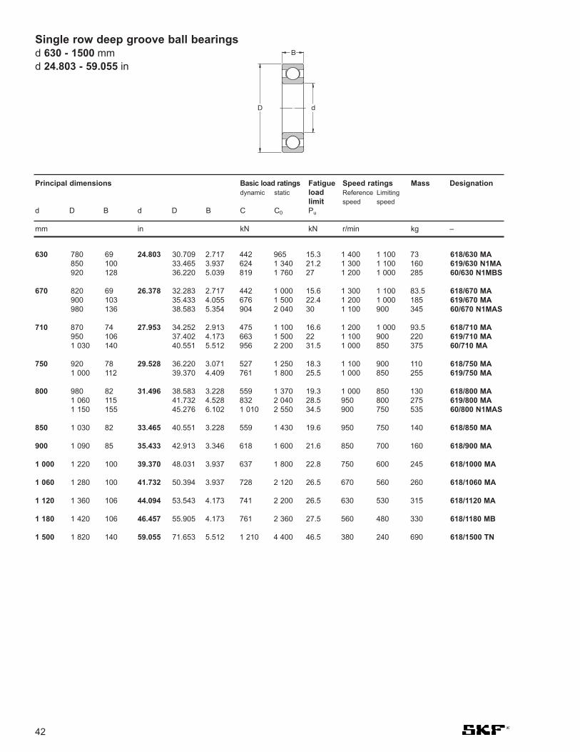
618/630 MA619/630 N1MA60/630 N1MBS
618/670 MA619/670 MA60/670 N1MAS
618/710 MA619/710 MA60/710 MA
618/750 MA619/750 MA
618/800 MA619/800 MA60/800 N1MAS
618/850 MA
618/900 MA
618/1000 MA
618/1060 MA
618/1120 MA
618/1180 MB
618/1500 TN
30.709 2.717 442 965 15.3 1 400 1 100 7333.465 3.937 624 1 340 21.2 1 300 1 100 16036.220 5.039 819 1 760 27 1 200 1 000 285
32.283 2.717 442 1 000 15.6 1 300 1 100 83.535.433 4.055 676 1 500 22.4 1 200 1 000 18538.583 5.354 904 2 040 30 1 100 900 345
34.252 2.913 475 1 100 16.6 1 200 1 000 93.537.402 4.173 663 1 500 22 1 100 900 22040.551 5.512 956 2 200 31.5 1 000 850 375
36.220 3.071 527 1 250 18.3 1 100 900 11039.370 4.409 761 1 800 25.5 1 000 850 255
38.583 3.228 559 1 370 19.3 1 000 850 13041.732 4.528 832 2 040 28.5 950 800 27545.276 6.102 1 010 2 550 34.5 900 750 535
40.551 3.228 559 1 430 19.6 950 750 140
42.913 3.346 618 1 600 21.6 850 700 160
48.031 3.937 637 1 800 22.8 750 600 245
50.394 3.937 728 2 120 26.5 670 560 260
53.543 4.173 741 2 200 26.5 630 530 315
55.905 4.173 761 2 360 27.5 560 480 330
71.653 5.512 1 210 4 400 46.5 380 240 690
24.803
26.378
27.953
29.528
31.496
33.465
35.433
39.370
41.732
44.094
46.457
59.055
780 69850 100920 128
820 69900 103980 136
870 74950 1061 030 140
920 781 000 112
980 821 060 1151 150 155
1 030 82
1 090 85
1 220 100
1 280 100
1 360 106
1 420 106
1 820 140
42
Single row deep groove ball bearingsd 630 - 1500 mmd 24.803 - 59.055 in
630
670
710
750
800
850
900
1 000
1 060
1 120
1 180
1 500
Principal dimensions Basic load ratings Fatigue Speed ratings Mass Designationdynamic static load Reference Limiting
limit speed speedd D B d D B C C0 Pu
mm in kN kN r/min kg –
D
B
d

43
Principal dimensions Basic load ratings Fatigue Speed ratings Mass Designationsdynamic static load Reference Limiting sealed sealed
limit speed speed both oned D B d D B C C0 Pu sides side
mm in kN kN r/min kg –
* SKF Explorer bearing
623-2Z 623-Z623-2RS1 623-RS1
628/4-2Z –638/4-2Z –619/4-2Z –604-2Z 604-Z624-2Z 624-Z
634-2Z 634-Z634-2RZ 634-RZ634-2RS1 634-RS1
628/5-2Z –638/5-2Z –619/5-2Z –
*625-2Z * 625-Z
*635-2Z * 635-Z*635-2RZ * 635-RZ*635-2RS1 * 635-RS1
628/6-2Z –619/6-2Z –
*626-2Z * 626-Z*626-2RSL * 626-RSL*626-2RSH * 626-RSH
628/7-2Z –619/7-2Z –
*607-2Z * 607-Z*607-2RSL * 607-RSL*607-2RSH * 607-RSH
*627-2Z * 627-Z*627-2RSL * 627-RSL*627-2RSH * 627-RSH
0.394 0.157 0.54 0.18 0.007 130 000 60 000 0.00150.394 0.157 0.54 0.18 0.007 – 40 000 0.0015
0.354 0.138 0.54 0.18 0.007 140 000 70 000 0.0010.354 0.157 0.54 0.18 0.007 140 000 70 000 0.00130.433 0.157 0.72 0.23 0.01 130 000 63 000 0.00170.472 0.157 0.81 0.28 0.012 120 000 60 000 0.00210.512 0.197 0.94 0.29 0.012 110 000 53 000 0.0031
0.630 0.197 1.11 0.38 0.016 95 000 48 000 0.00540.630 0.197 1.11 0.38 0.016 95 000 48 000 0.00540.630 0.197 1.11 0.38 0.016 – 28 000 0.0054
0.433 0.157 0.64 0.26 0.011 120 000 60 000 0.00140.433 0.197 0.64 0.26 0.011 120 000 60 000 0.00160.512 0.157 0.88 0.34 0.014 110 000 53 000 0.00250.630 0.197 1.14 0.38 0.016 95 000 48 000 0.005
0.748 0.236 2.34 0.95 0.04 80 000 40 000 0.0090.748 0.236 2.34 0.95 0.04 80 000 40 000 0.0090.748 0.236 2.34 0.95 0.04 – 24 000 0.009
0.512 0.197 0.88 0.35 0.015 110 000 53 000 0.00260.591 0.197 1.24 0.48 0.02 100 000 50 000 0.0039
0.748 0.236 2.34 0.95 0.04 80 000 40 000 0.00840.748 0.236 2.34 0.95 0.04 80 000 40 000 0.00840.748 0.236 2.34 0.95 0.04 – 24 000 0.0084
0.551 0.197 0.956 0.4 0.017 100 000 50 000 0.00310.669 0.197 1.48 0.56 0.024 90 000 45 000 0.0049
0.748 0.236 2.34 0.95 0.04 85 000 43 000 0.00750.748 0.236 2.34 0.95 0.04 85 000 43 000 0.00750.748 0.236 2.34 0.95 0.04 – 24 000 0.0075
0.866 0.276 3.45 1.37 0.057 70 000 36 000 0.0130.866 0.276 3.45 1.37 0.057 70 000 36 000 0.0120.866 0.276 3.45 1.37 0.057 – 22 000 0.012
0.118
0.157
0.197
0.236
0.276
10 410 4
9 3.59 411 412 413 5
16 516 516 5
11 411 513 416 5
19 619 619 6
13 515 5
19 619 619 6
14 517 5
19 619 619 6
22 722 722 7
Sealed single row deep groove ball bearingsd 3 - 7 mm
d 0.118 - 0.276 in
3
4
5
6
7
D
B
d

44
Principal dimensions Basic load ratings Fatigue Speed ratings Mass Designationsdynamic static load Reference Limiting sealed sealed
limit speed speed both oned D B d D B C C0 Pu sides side
mm in kN kN r/min kg –
Sealed single row deep groove ball bearingsd 8 - 10 mmd 0.315 - 0.394 in
628/8-2Z –628/8-2RS1 –638/8-2Z –
619/8-2Z –619/8-2RS1 –607/8-2Z 607/8-Z
*608-2Z * 608-Z*608-2RSL * 608-RSL*608-2RSH * 608-RSH630/8-2RS1 –
*628-2Z * 628-Z*628-2RZ * 628-RZ*628-2RS1 * 628-RS1638-2RZ 638-RZ
628/9-2Z 628/9-Z628/9-2RS1 –619/9-2Z –
*609-2Z * 609-Z*609-2RSL * 609-RSL*609-2RSH * 609-RSH
*629-2Z * 629-Z*629-2RSL * 629-RSL*629-2RSH * 629-RSH
61800-2Z –61800-2RS1 –61900-2Z –61900-2RS1 –
*6000-2Z * 6000-Z*6000-2RSL * 6000-RSL*6000-2RSH * 6000-RSH63000-2RS1 –16100-2Z –
*6200-2Z * 6200-Z*6200-2RSL * 6200-RSL*6200-2RSH * 6200-RSH62200-2RS1 –
*6300-2Z * 6300-Z*6300-2RSL * 6300-RSL*6300-2RSH * 6300-RSH62300-2RS1 –
0.630 0.197 1.33 0.57 0.024 90 000 45 000 0.00360.630 0.197 1.33 0.57 0.024 – 26 000 0.00360.630 0.236 1.33 0.57 0.024 90 000 45 000 0.0043
0.748 0.236 1.9 0.74 0.031 80 000 40 000 0.00710.748 0.236 1.9 0.74 0.031 – 24 000 0.00710.748 0.236 2.21 0.95 0.04 85 000 43 000 0.0072
0.866 0.276 3.45 1.37 0.057 75 000 38 000 0.0120.866 0.276 3.45 1.37 0.057 75 000 38 000 0.0120.866 0.276 3.45 1.37 0.057 – 22 000 0.0120.866 0.433 3.45 1.37 0.057 – 22 000 0.016
0.945 0.315 3.9 1.66 0.071 63 000 32 000 0.0170.945 0.315 3.9 1.66 0.071 63 000 32 000 0.0170.945 0.315 3.9 1.66 0.071 – 19 000 0.0171.102 0.354 4.62 1.96 0.083 60 000 30 000 0.03
0.669 0.197 1.43 0.64 0.027 85 000 43 000 0.00430.669 0.197 1.43 0.64 0.027 – 24 000 0.00430.787 0.236 2.08 0.87 0.036 80 000 38 000 0.0076
0.945 0.276 3.9 1.66 0.071 70 000 34 000 0.0140.945 0.276 3.9 1.66 0.071 70 000 34 000 0.0140.945 0.276 3.9 1.66 0.071 – 19 000 0.014
1.024 0.315 4.75 1.96 0.083 60 000 30 000 0.021.024 0.315 4.75 1.96 0.083 60 000 30 000 0.021.024 0.315 4.75 1.96 0.083 – 19 000 0.02
0.748 0.197 1.38 0.59 0.025 80 000 38 000 0.00550.748 0.197 1.38 0.59 0.025 – 22 000 0.00550.866 0.236 2.08 0.85 0.036 75 000 36 000 0.010.866 0.236 2.08 0.85 0.036 – 20 000 0.011.024 0.315 4.75 1.96 0.083 67 000 34 000 0.0191.024 0.315 4.75 1.96 0.083 67 000 34 000 0.0191.024 0.315 4.75 1.96 0.083 – 19 000 0.0191.024 0.472 4.62 1.96 0.083 – 19 000 0.0251.102 0.315 4.62 1.96 0.083 63 000 32 000 0.022
1.181 0.354 5.4 2.36 0.1 56 000 28 000 0.0321.181 0.354 5.4 2.36 0.1 56 000 28 000 0.0321.181 0.354 5.4 2.36 0.1 – 17 000 0.0321.181 0.551 5.07 2.36 0.1 – 17 000 0.04
1.378 0.433 8.52 3.4 0.143 50 000 26 000 0.0531.378 0.433 8.52 3.4 0.143 50 000 26 000 0.0531.378 0.433 8.52 3.4 0.143 – 15 000 0.0531.378 0.669 8.06 3.4 0.143 – 15 000 0.06
0.315
0.354
0.394
16 516 516 6
19 619 619 6
22 722 722 722 11
24 824 824 828 9
17 517 520 6
24 724 724 7
26 826 826 8
19 519 522 622 626 826 826 826 1228 8
30 930 930 930 14
35 1135 1135 1135 17
8
9
10
* SKF Explorer bearing
D
B
d

45
Principal dimensions Basic load ratings Fatigue Speed ratings Mass Designationsdynamic static load Reference Limiting sealed sealed
limit speed speed both oned D B d D B C C0 Pu sides side
mm in kN kN r/min kg –
* SKF Explorer bearing
61801-2Z –61801-2RS1 –61901-2Z –61901-2RS1 –
*6001-2Z * 6001-Z*6001-2RSL * 6001-RSL*6001-2RSH * 6001-RSH63001-2RS1 –16101-2Z –16101-2RS1 –
*6201-2Z * 6201-Z*6201-2RSL * 6201-RSL*6201-2RSH * 6201-RSH62201-2RS1 –
*6301-2Z * 6301-Z*6301-2RSL * 6301-RSL*6301-2RSH * 6301-RSH62301-2RS1 –
61802-2Z –61802-2RS1 –61902-2Z –61902-2RZ –61902-2RS1 –
*16002-2Z * 16002-Z*6002-2Z * 6002-Z*6002-2RSL * 6002-RSL*6002-2RSH * 6002-RSH63002-2RS1 –
*6202-2Z * 6202-Z*6202-2RSL * 6202-RSL*6202-2RSH * 6202-RSH62202-2RS1 –
*6302-2Z * 6302-Z*6302-2RSL * 6302-RSL*6302-2RSH * 6302–RSH62302-2RS1 –
0.827 0.197 1.43 0.67 0.028 70 000 36 000 0.00630.827 0.197 1.43 0.67 0.028 – 20 000 0.00630.945 0.236 2.25 0.98 0.043 67 000 32 000 0.0110.945 0.236 2.25 0.98 0.043 – 19 000 0.0111.102 0.315 5.4 2.36 0.1 60 000 30 000 0.0221.102 0.315 5.4 2.36 0.1 60 000 30 000 0.0221.102 0.315 5.4 2.36 0.1 – 17 000 0.0221.102 0.472 5.07 2.36 0.1 – 17 000 0.0291.181 0.315 5.07 2.36 0.1 56 000 28 000 0.0231.181 0.315 5.07 2.36 0.1 – 16 000 0.023
1.260 0.394 7.28 3.1 0.132 50 000 26 000 0.0371.260 0.394 7.28 3.1 0.132 50 000 26 000 0.0371.260 0.394 7.28 3.1 0.132 – 15 000 0.0371.260 0.551 6.89 3.1 0.132 – 15 000 0.045
1.457 0.472 10.1 4.15 0.176 45 000 22 000 0.061.457 0.472 10.1 4.15 0.176 45 000 22 000 0.061.457 0.472 10.1 4.15 0.176 – 14 000 0.061.457 0.669 9.75 4.15 0.176 – 14 000 0.07
0.945 0.197 1.56 0.8 0.034 60 000 30 000 0.00740.945 0.197 1.56 0.8 0.034 – 17 000 0.00741.102 0.276 4.36 2.24 0.095 56 000 28 000 0.0161.102 0.276 4.36 2.24 0.095 56 000 28 000 0.0161.102 0.276 4.36 2.24 0.095 – 16 000 0.0161.260 0.315 5.85 2.85 0.12 50 000 26 000 0.0251.260 0.354 5.85 2.85 0.12 50 000 26 000 0.031.260 0.354 5.85 2.85 0.12 50 000 26 000 0.031.260 0.354 5.85 2.85 0.12 – 14 000 0.031.260 0.512 5.59 2.85 0.12 – 14 000 0.039
1.378 0.433 8.06 3.75 0.16 43 000 22 000 0.0451.378 0.433 8.06 3.75 0.16 43 000 22 000 0.0451.378 0.433 8.06 3.75 0.16 – 13 000 0.0451.378 0.551 7.8 3.75 0.16 – 13 000 0.0541.654 0.512 11.9 5.4 0.228 38 000 19 000 0.0821.654 0.512 11.9 5.4 0.228 38 000 19 000 0.0821.654 0.512 11.9 5.4 0.228 – 12 000 0.0821.654 0.669 11.4 5.4 0.228 – 12 000 0.11
0.472
0.591
21 521 524 624 628 828 828 828 1230 830 8
32 1032 1032 1032 14
37 1237 1237 1237 17
24 524 528 728 728 732 832 932 932 932 13
35 1135 1135 1135 1442 1342 1342 1342 17
Sealed single row deep groove ball bearingsd 12 - 15 mm
d 0.472 - 0.591 in
12
15

46
Principal dimensions Basic load ratings Fatigue Speed ratings Mass Designationsdynamic static load Reference Limiting sealed sealed
limit speed speed both oned D B d D B C C0 Pu sides side
mm in kN kN r/min kg –
Sealed single row deep groove ball bearingsd 17 - 22 mmd 0.669 - 0.866 in
* SKF Explorer bearing
61803-2Z –61803-2RZ –61803-2RS1 –61903-2Z –61903-2RZ –61903-2RS1 –
*16003-2Z –
*6003-2Z * 6003-Z*6003-2RSL * 6003-RSL*6003-2RSH * 6003-RSH63003-2RS1 –
*6203-2Z * 6203-Z*6203-2RSL * 6203-RSL*6203-2RSH * 6203-RSH62203-2RS1 –
*6303-2Z * 6303-Z*6303-2RSL * 6303-RSL*6303-2RSH * 6303-RSH62303-2RS1 –
61804-2RZ –61804-2RS1 –61904-2RZ –61904-2RS1 –
*6004-2Z * 6004-Z*6004-2RSL * 6004-RSL*6004-2RSH * 6004-RSH63004-2RS1 –
*6204-2Z * 6204-Z*6204-2RSL * 6204-RSL*6204-2RSH * 6204-RSH62204-2RS1 –
*6304-2Z * 6304-Z*6304-2RSL * 6304-RSL*6304-2RSH * 6304-RSH62304-2RS1 –
62/22-2RS1 –
1.024 0.197 1.68 0.93 0.039 56 000 28 000 0.00821.024 0.197 1.68 0.93 0.039 56 000 28 000 0.00821.024 0.197 1.68 0.93 0.039 – 16 000 0.00821.181 0.276 4.62 2.55 0.108 50 000 26 000 0.0181.181 0.276 4.62 2.55 0.108 50 000 26 000 0.0181.181 0.276 4.62 2.55 0.108 – 14 000 0.0181.378 0.315 6.37 3.25 0.137 45 000 22 000 0.032
1.378 0.394 6.37 3.25 0.137 45 000 22 000 0.0391.378 0.394 6.37 3.25 0.137 45 000 22 000 0.0391.378 0.394 6.37 3.25 0.137 – 13 000 0.0391.378 0.551 6.05 3.25 0.137 – 13 000 0.0521.575 0.472 9.95 4.75 0.2 38 000 19 000 0.0651.575 0.472 9.95 4.75 0.2 38 000 19 000 0.0651.575 0.472 9.95 4.75 0.2 – 12 000 0.0651.575 0.630 9.56 4.75 0.2 – 12 000 0.0831.850 0.551 14.3 6.55 0.275 34 000 17 000 0.121.850 0.551 14.3 6.55 0.275 34 000 17 000 0.121.850 0.551 14.3 6.55 0.275 – 11 000 0.121.850 0.748 13.5 6.55 0.275 – 11 000 0.15
1.260 0.276 4.03 2.32 0.104 45 000 22 000 0.0181.260 0.276 4.03 2.32 0.104 – 13 000 0.0181.457 0.354 6.37 3.65 0.156 43 000 20 000 0.0381.457 0.354 6.37 3.65 0.156 – 12 000 0.0381.654 0.472 9.95 5 0.212 38 000 19 000 0.0691.654 0.472 9.95 5 0.212 38 000 19 000 0.0691.654 0.472 9.95 5 0.212 – 11 000 0.0691.654 0.630 9.36 5 0.212 – 11 000 0.086
1.850 0.551 13.5 6.55 0.28 32 000 17 000 0.111.850 0.551 13.5 6.55 0.28 32 000 17 000 0.111.850 0.551 13.5 6.55 0.28 – 10 000 0.111.850 0.709 12.7 6.55 0.28 – 10 000 0.13
2.047 0.591 16.8 7.8 0.335 30 000 15 000 0.142.047 0.591 16.8 7.8 0.335 30 000 15 000 0.142.047 0.591 16.8 7.8 0.335 – 9 500 0.142.047 0.827 15.9 7.8 0.335 – 9 500 0.2
1.969 0.551 14 7.65 0.325 – 9 000 0.12
0.669
0.787
0.866
26 526 526 530 730 730 735 8
35 1035 1035 1035 1440 1240 1240 1240 1647 1447 1447 1447 19
32 732 737 937 942 1242 1242 1242 16
47 1447 1447 1447 18
52 1552 1552 1552 21
50 14
17
20
22
D
B
d

47
Principal dimensions Basic load ratings Fatigue Speed ratings Mass Designationsdynamic static load Reference Limiting sealed sealed
limit speed speed both oned D B d D B C C0 Pu sides side
mm in kN kN r/min kg –
61805-2RZ –61805-2RS1 –61905-2RZ –61905-2RS1 –
*6005-2Z * 6005-Z*6005-2RSL * 6005-RSL*6005-2RSH * 6005-RSH63005-2RS1 –
*6205-2Z * 6205-Z*6205-2RSL * 6205-RSL*6205-2RSH * 6205-RSH62205-2RS1 –
*6305-2Z * 6305-Z*6305-2RZ * 6305-RZ*6305-2RS1 * 6305-RS162305-2RS1 –
61806-2RZ –61806-2RS1 –61906-2RZ –61906-2RS1 –
*6006-2Z * 6006-Z*6006-2RZ * 6006-RZ*6006-2RS1 * 6006-RS163006-2RS1 –
*6206-2Z * 6206-Z*6206-2RZ * 6206-RZ*6206-2RS1 * 6206-RS162206-2RS1 –
*6306-2Z * 6306-Z*6306-2RZ * 6306-RZ*6306-2RS1 * 6306-RS162306-2RS1 –
1.457 0.276 4.36 2.6 0.125 38 000 19 000 0.0221.457 0.276 4.36 2.6 0.125 – 11 000 0.0221.654 0.354 7.02 4.3 0.193 36 000 18 000 0.0451.654 0.354 7.02 4.3 0.193 – 10 000 0.0451.850 0.472 11.9 6.55 0.275 32 000 16 000 0.081.850 0.472 11.9 6.55 0.275 32 000 16 000 0.081.850 0.472 11.9 6.55 0.275 – 9 500 0.081.850 0.630 11.2 6.55 0.275 – 9 500 0.1
2.047 0.591 14.8 7.8 0.335 28 000 14 000 0.132.047 0.591 14.8 7.8 0.335 28 000 14 000 0.132.047 0.591 14.8 7.8 0.335 – 8 500 0.132.047 0.709 14 7.8 0.335 – 8 500 0.15
2.441 0.669 23.4 11.6 0.49 24 000 13 000 0.232.441 0.669 23.4 11.6 0.49 24 000 13 000 0.232.441 0.669 23.4 11.6 0.49 – 7 500 0.232.441 0.945 22.5 11.6 0.49 – 7 500 0.32
1.654 0.276 4.49 2.9 0.146 32 000 16 000 0.0271.654 0.276 4.49 2.9 0.146 – 9 500 0.0271.850 0.354 7.28 4.55 0.212 30 000 15 000 0.0511.850 0.354 7.28 4.55 0.212 – 8 500 0.051
2.165 0.512 13.8 8.3 0.355 28 000 14 000 0.122.165 0.512 13.8 8.3 0.355 28 000 14 000 0.122.165 0.512 13.8 8.3 0.355 – 8 000 0.122.165 0.748 13.3 8.3 0.355 – 8 000 0.16
2.441 0.630 20.3 11.2 0.475 24 000 12 000 0.22.441 0.630 20.3 11.2 0.475 24 000 12 000 0.22.441 0.630 20.3 11.2 0.475 – 7 500 0.22.441 0.787 19.5 11.2 0.475 – 7 500 0.24
2.835 0.748 29.6 16 0.67 20 000 11 000 0.352.835 0.748 29.6 16 0.67 20 000 11 000 0.352.835 0.748 29.6 16 0.67 – 6 300 0.352.835 1.063 28.1 16 0.67 – 6 300 0.48
0.984
1.181
37 737 742 942 947 1247 1247 1247 16
52 1552 1552 1552 18
62 1762 1762 1762 24
42 742 747 947 9
55 1355 1355 1355 19
62 1662 1662 1662 20
72 1972 1972 1972 27
Sealed single row deep groove ball bearingsd 25 - 30 mm
d 0.984 - 1.181 in
25
30
* SKF Explorer bearing

Sealed single row deep groove ball bearingsd 35 - 40 mmd 1.378 - 1.575 in
48
Principal dimensions Basic load ratings Fatigue Speed ratings Mass Designationsdynamic static load Reference Limiting sealed sealed
limit speed speed both oned D B d D B C C0 Pu sides side
mm in kN kN r/min kg –
D
B
d
* SKF Explorer bearing
61807-2RZ –61807-2RS1 –61907-2RZ –61907-2RS1 –
*6007-2Z * 6007-Z*6007-2RZ * 6007-RZ*6007-2RS1 * 6007-RS163007-2RS1 –
*6207-2Z * 6207-Z*6207-2RS1 * 6207-RS162207-2RS1 –
*6307-2Z * 6307-Z*6307-2RS1 * 6307-RS162307-2RS1 –
61808-2RZ –61808-2RS1 –61908-2RZ –61908-2RS1 –
*6008-2Z * 6008-Z*6008-2RZ * 6008-RZ*6008-2RS1 * 6008-RS163008-2RS1 –
*6208-2Z * 6208-Z*6208-2RZ * 6208-RZ*6208-2RS1 * 6208-RS162208-2RS1 –
*6308-2Z * 6308-Z*6308-2RZ * 6308-RZ*6308-2RS1 * 6308-RS162308-2RS1 –
1.850 0.276 4.75 3.2 0.166 28 000 14 000 0.031.850 0.276 4.75 3.2 0.166 – 8 000 0.032.165 0.394 9.56 6.8 0.29 26 000 13 000 0.082.165 0.394 9.56 6.8 0.29 – 7 500 0.08
2.441 0.551 16.8 10.2 0.44 24 000 12 000 0.162.441 0.551 16.8 10.2 0.44 24 000 12 000 0.162.441 0.551 16.8 10.2 0.44 – 7 000 0.162.441 0.787 15.9 10.2 0.44 – 7 000 0.21
2.835 0.669 27 15.3 0.655 20 000 10 000 0.292.835 0.669 27 15.3 0.655 – 6 300 0.292.835 0.906 25.5 15.3 0.655 – 6 300 0.37
3.150 0.827 35.1 19 0.815 19 000 9 500 0.463.150 0.827 35.1 19 0.815 – 6 000 0.463.150 1.220 33.2 19 0.815 – 6 000 0.66
2.047 0.276 4.94 3.45 0.186 26 000 13 000 0.0342.047 0.276 4.94 3.45 0.186 – 7 500 0.0342.441 0.472 13.8 10 0.425 24 000 12 000 0.122.441 0.472 13.8 10 0.425 – 6 700 0.12
2.677 0.591 17.8 11.6 0.49 22 000 11 000 0.192.677 0.591 17.8 11.6 0.49 22 000 11 000 0.192.677 0.591 17.8 11.6 0.49 – 6 300 0.192.677 0.827 16.8 11.6 0.49 – 6 300 0.26
3.150 0.709 32.5 19 0.8 18 000 9 000 0.373.150 0.709 32.5 19 0.8 18 000 9 000 0.373.150 0.709 32.5 19 0.8 – 5 600 0.373.150 0.906 30.7 19 0.8 – 5 600 0.44
3.543 0.906 42.3 24 1.02 17 000 8 500 0.633.543 0.906 42.3 24 1.02 17 000 8 500 0.633.543 0.906 42.3 24 1.02 – 5 000 0.633.543 1.299 41 24 1.02 – 5 000 0.89
1.378
1.575
47 747 755 1055 10
62 1462 1462 1462 20
72 1772 1772 23
80 2180 2180 31
52 752 762 1262 12
68 1568 1568 1568 21
80 1880 1880 1880 23
90 2390 2390 2390 33
35
40

49
Principal dimensions Basic load ratings Fatigue Speed ratings Mass Designationsdynamic static load Reference Limiting sealed sealed
limit speed speed both oned D B d D B C C0 Pu sides side
mm in kN kN r/min kg –
61809-2RZ –61809-2RS1 –61909-2RZ –61909-2RS1 –
*6009-2Z * 6009-Z*6009-2RS1 * 6009-RS163009-2RS1 –
*6209-2Z * 6209-Z*6209-2RS1 * 6209-RS162209-2RS1 –
*6309-2Z * 6309-Z*6309-2RS1 * 6309-RS162309-2RS1 –
61810-2RZ –61810-2RS1 –61910-2RZ –61910-2RS1 –
*6010-2Z * 6010-Z*6010-2RZ * 6010-RZ*6010-2RS1 * 6010-RS163010-2RS1 –
*6210-2Z * 6210-Z*6210-2RZ * 6210-RZ*6210-2RS1 * 6210-RS162210-2RS1 –
*6310-2Z * 6310-Z*6310-2RS1 * 6310-RS162310-2RS1 –
2.283 0.276 6.63 6.1 0.26 22 000 11 000 0.042.283 0.276 6.63 6.1 0.26 – 6 700 0.042.677 0.472 14 10.8 0.465 20 00 10 000 0.142.677 0.472 14 10.8 0.465 – 6 000 0.14
2.953 0.630 22.1 14.6 0.64 20 000 10 000 0.252.953 0.630 22.1 14.6 0.64 – 5 600 0.252.953 0.906 20.8 14.6 0.64 – 5 600 0.34
3.346 0.748 35.1 21.6 0.915 17 000 8 500 0.413.346 0.748 35.1 21.6 0.915 – 5 000 0.413.346 0.906 33.2 21.6 0.915 – 5 000 0.48
3.937 0.984 55.3 31.5 1.34 15 000 7 500 0.833.937 0.984 55.3 31.5 1.34 – 4 500 0.833.937 1.417 52.7 31.5 1.34 – 4 500 1.15
2.559 0.276 6.76 6.8 0.285 20 000 10 000 0.0522.559 0.276 6.76 6.8 0.285 – 6 000 0.0522.835 0.472 14.6 11.8 0.5 19 000 9 500 0.142.835 0.472 14.6 11.8 0.5 – 5 600 0.14
3.150 0.630 22.9 16 0.71 18 000 9 000 0.263.150 0.630 22.9 16 0.71 18 000 9 000 0.263.150 0.630 22.9 16 0.71 – 5 000 0.263.150 0.906 21.6 16 0.71 – 5 000 0.37
3.543 0.787 37.1 23.2 0.98 15 000 8 000 0.463.543 0.787 37.1 23.2 0.98 15 000 8 000 0.463.543 0.787 37.1 23.2 0.98 – 4 800 0.463.543 0.906 35.1 23.2 0.98 – 4 800 0.52
4.331 1.063 65 38 1.6 13 000 6 700 1.054.331 1.063 65 38 1.6 – 4 300 1.054.331 1.575 61.8 38 1.6 – 4 300 1.55
1.772
1.969
58 758 768 1268 12
75 1675 1675 23
85 1985 1985 23
100 25100 25100 36
65 765 772 1272 12
80 1680 1680 1680 23
90 2090 2090 2090 23
110 27110 27110 40
Sealed single row deep groove ball bearingsd 45 - 50 mm
d 1.772 - 1.969 in
45
50
* SKF Explorer bearing

Sealed single row deep groove ball bearingsd 55 - 65 mmd 2.165 - 2.559 in
50
Principal dimensions Basic load ratings Fatigue Speed ratings Mass Designationsdynamic static load Reference Limiting sealed sealed
limit speed speed both oned D B d D B C C0 Pu sides side
mm in kN kN r/min kg –
D
B
d
* SKF Explorer bearing
61811-2RZ –61811-2RS1 –61911-2RZ –61911-2RS1 –
*6011-2Z * 6011-Z*6011-2RS1 * 6011-RS1
*6211-2Z * 6211-Z*6211-2RS1 * 6211-RS162211-2RS1 –
*6311-2Z * 6311-Z*6311-2RS1 * 6311-RS162311-2RS1 –
61812-2RZ –61812-2RS1 –61912-2RZ –61912-2RS1 –
*6012-2Z * 6012-Z*6012-2RZ * 6012-RZ*6012-2RS1 * 6012-RS1
*6212-2Z * 6212-Z*6212-2RS1 * 6212-RS162212-2RS1 –
*6312-2Z * 6312-Z*6312-2RS1 * 6312-RS162312-2RS1 –
61813-2RZ –61813-2RS1 –61913-2RZ –61913-2RS1 –
*6013-2Z * 6013-Z*6013-2RS1 * 6013-RS1
*6213-2Z * 6213-Z*6213-2RS1 * 6213-RS162213-2RS1 –
*6313-2Z * 6313-Z*6313-2RS1 * 6313-RS162313-2RS1 –
2.835 0.354 9.04 8.8 0.375 19 000 9 500 0.0832.835 0.354 9.04 8.8 0.375 – 5 300 0.0833.150 0.512 16.5 14 0.6 17 000 8 500 0.193.150 0.512 16.5 14 0.6 – 5 000 0.19
3.543 0.709 29.6 21.2 0.9 16 000 8 000 0.393.543 0.709 29.6 21.2 0.9 – 4 500 0.39
3.937 0.827 46.2 29 1.25 14 000 7 000 0.613.937 0.827 46.2 29 1.25 – 4 300 0.613.937 0.984 43.6 29 1.25 – 4 300 0.7
4.724 1.142 74.1 45 1.9 12 000 6 300 1.354.724 1.142 74.1 45 1.9 – 3 800 1.354.724 1.693 71.5 45 1.9 – 3 800 1.95
3.071 0.394 11.9 11.4 0.49 17 000 8 500 0.113.071 0.394 11.9 11.4 0.49 – 4 800 0.113.346 0.512 16.5 14.3 0.6 16 000 8 000 0.23.346 0.512 16.5 14.3 0.6 – 4 500 0.2
3.740 0.709 30.7 23.2 0.98 15 000 7 500 0.423.740 0.709 30.7 23.2 0.98 15 000 7 500 0.423.740 0.709 30.7 23.2 0.98 – 4 300 0.42
4.331 0.866 55.3 36 1.53 13 000 6 300 0.784.331 0.866 55.3 36 1.53 – 4 000 0.784.331 1.102 52.7 36 1.53 – 4 000 0.97
5.118 1.220 85.2 52 2.2 11 000 5 600 1.75.118 1.220 85.2 52 2.2 – 3 400 1.75.118 1.811 81.9 52 2.2 – 3 400 2.5
3.346 0.394 12.4 12.7 0.54 16 000 8 000 0.133.346 0.394 12.4 12.7 0.54 – 4 500 0.133.543 0.512 17.4 16 0.68 15 000 7 500 0.223.543 0.512 17.4 16 0.68 – 4 300 0.22
3.937 0.709 31.9 25 1.06 14 000 7 000 0.443.937 0.709 31.9 25 1.06 – 4 000 0.44
4.724 0.906 58.5 40.5 1.73 12 000 6 000 0.994.724 0.906 58.5 40.5 1.73 – 3 600 0.994.724 1.220 55.9 40.5 1.73 – 3 600 1.25
5.512 1.299 97.5 60 2.5 10 000 5 300 2.15.512 1.299 97.5 60 2.5 – 3 200 2.15.512 1.890 92.3 60 2.5 – 3 200 3
2.165
2.362
2.559
72 972 980 1380 13
90 1890 18
100 21100 21100 25
120 29120 29120 43
78 1078 1085 1385 13
95 1895 1895 18
110 22110 22110 28
130 31130 31130 46
85 1085 1090 1390 13
100 18100 18
120 23120 23120 31
140 33140 33140 48
55
60
65

51
Principal dimensions Basic load ratings Fatigue Speed ratings Mass Designationsdynamic static load Reference Limiting sealed sealed
limit speed speed both oned D B d D B C C0 Pu sides side
mm in kN kN r/min kg –
61814-2RZ –61814-2RS1 –61914-2RZ –61914-2RS1 –
*6014-2Z * 6014-Z*6014-2RS1 * 6014-RS1
*6214-2Z * 6214-Z*6214-2RS1 * 6214-RS162214-2RS1 –
*6314-2Z * 6314-Z*6314-2RS1 * 6314-RS162314-2RS1 –
61815-2RZ –61815-2RS1 –61915-2RZ –61915-2RS1 –
*6015-2Z * 6015-Z*6015-2RZ * 6015-RZ*6015-2RS1 * 6015-RS1
*6215-2Z * 6215-Z*6215-2RS1 * 6215-RS1*6315-2Z * 6315-Z*6315-2RS1 * 6315-RS1
61816-2RZ –61816-2RS1 –61916-2RZ –61916-2RS1 –
*6016-2Z * 6016-Z*6016-2RS1 * 6016-RS1
*6216-2Z * 6216-Z*6216-2RS1 * 6216-RS1*6316-2Z * 6316-Z*6316-2RS1 * 6316-RS1
3.543 0.394 12.4 13.2 0.56 15 000 7 500 0.143.543 0.394 12.4 13.2 0.56 – 4 300 0.143.937 0.630 23.8 21.2 0.9 14 000 7 000 0.353.937 0.630 23.8 21.2 0.9 – 4 000 0.35
4.331 0.787 39.7 31 1.32 13 000 6 300 0.64.331 0.787 39.7 31 1.32 – 3 600 0.6
4.921 0.945 63.7 45 1.9 11 000 5 600 1.14.921 0.945 63.7 45 1.9 – 3 400 1.14.921 1.220 60.5 45 1.9 – 3 400 1.3
5.906 1.378 111 68 2.75 9 500 5 000 2.55.906 1.378 111 68 2.75 – 3 000 2.55.906 2.008 104 68 2.75 – 3 000 3.55
3.740 0.394 12.7 14.3 0.61 14 000 7 000 0.153.740 0.394 12.7 14.3 0.61 – 4 000 0.154.134 0.630 24.2 19.3 0.965 13 000 6 300 0.374.134 0.630 24.2 19.3 0.965 – 3 600 0.37
4.528 0.787 41.6 33.5 1.43 12 000 6 000 0.644.528 0.787 41.6 33.5 1.43 12 000 6 000 0.644.528 0.787 41.6 33.5 1.43 – 3 400 0.64
5.118 0.984 68.9 49 2.04 10 000 5 300 1.25.118 0.984 68.9 49 2.04 – 3 200 1.26.299 1.457 119 76.5 3 9 000 4 500 36.299 1.457 119 76.5 3 – 2 800 3
3.937 0.394 13 15 0.64 13 000 6 300 0.153.937 0.394 13 15 0.64 – 3 600 0.154.331 0.630 25.1 20.4 1.02 12 000 6 000 0.44.331 0.630 25.1 20.4 1.02 – 3 400 0.4
4.921 0.866 49.4 40 1.66 11 000 5 600 0.854.921 0.866 49.4 40 1.66 – 3 200 0.85
5.512 1.024 72.8 55 2.2 9 500 4 800 1.45.512 1.024 72.8 55 2.2 – 3 000 1.46.693 1.535 130 86.5 3.25 8 500 4 300 3.66.693 1.535 130 86.5 3.25 – 2 600 3.6
2.756
2.953
3.150
90 1090 10100 16100 16
110 20110 20
125 24125 24125 31
150 35150 35150 51
95 1095 10105 16105 16
115 20115 20115 20
130 25130 25160 37160 37
100 10100 10110 16110 16
125 22125 22
140 26140 26170 39170 39
Sealed single row deep groove ball bearingsd 70 - 80 mm
d 2.756 - 3.150 in
70
75
80
* SKF Explorer bearing
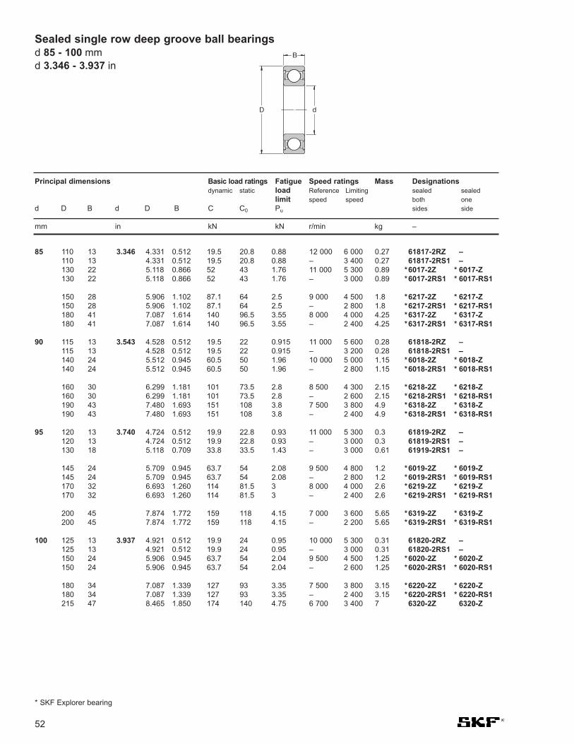
52
Principal dimensions Basic load ratings Fatigue Speed ratings Mass Designationsdynamic static load Reference Limiting sealed sealed
limit speed speed both oned D B d D B C C0 Pu sides side
mm in kN kN r/min kg –
Sealed single row deep groove ball bearingsd 85 - 100 mmd 3.346 - 3.937 in
* SKF Explorer bearing
61817-2RZ –61817-2RS1 –
*6017-2Z * 6017-Z*6017-2RS1 * 6017-RS1
*6217-2Z * 6217-Z*6217-2RS1 * 6217-RS1*6317-2Z * 6317-Z*6317-2RS1 * 6317-RS1
61818-2RZ –61818-2RS1 –
*6018-2Z * 6018-Z*6018-2RS1 * 6018-RS1
*6218-2Z * 6218-Z*6218-2RS1 * 6218-RS1*6318-2Z * 6318-Z*6318-2RS1 * 6318-RS1
61819-2RZ –61819-2RS1 –61919-2RS1 –
*6019-2Z * 6019-Z*6019-2RS1 * 6019-RS1*6219-2Z * 6219-Z*6219-2RS1 * 6219-RS1
*6319-2Z * 6319-Z*6319-2RS1 * 6319-RS1
61820-2RZ –61820-2RS1 –
*6020-2Z * 6020-Z*6020-2RS1 * 6020-RS1
*6220-2Z * 6220-Z*6220-2RS1 * 6220-RS16320-2Z 6320-Z
4.331 0.512 19.5 20.8 0.88 12 000 6 000 0.274.331 0.512 19.5 20.8 0.88 – 3 400 0.275.118 0.866 52 43 1.76 11 000 5 300 0.895.118 0.866 52 43 1.76 – 3 000 0.89
5.906 1.102 87.1 64 2.5 9 000 4 500 1.85.906 1.102 87.1 64 2.5 – 2 800 1.87.087 1.614 140 96.5 3.55 8 000 4 000 4.257.087 1.614 140 96.5 3.55 – 2 400 4.25
4.528 0.512 19.5 22 0.915 11 000 5 600 0.284.528 0.512 19.5 22 0.915 – 3 200 0.285.512 0.945 60.5 50 1.96 10 000 5 000 1.155.512 0.945 60.5 50 1.96 – 2 800 1.15
6.299 1.181 101 73.5 2.8 8 500 4 300 2.156.299 1.181 101 73.5 2.8 – 2 600 2.157.480 1.693 151 108 3.8 7 500 3 800 4.97.480 1.693 151 108 3.8 – 2 400 4.9
4.724 0.512 19.9 22.8 0.93 11 000 5 300 0.34.724 0.512 19.9 22.8 0.93 – 3 000 0.35.118 0.709 33.8 33.5 1.43 – 3 000 0.61
5.709 0.945 63.7 54 2.08 9 500 4 800 1.25.709 0.945 63.7 54 2.08 – 2 800 1.26.693 1.260 114 81.5 3 8 000 4 000 2.66.693 1.260 114 81.5 3 – 2 400 2.6
7.874 1.772 159 118 4.15 7 000 3 600 5.657.874 1.772 159 118 4.15 – 2 200 5.65
4.921 0.512 19.9 24 0.95 10 000 5 300 0.314.921 0.512 19.9 24 0.95 – 3 000 0.315.906 0.945 63.7 54 2.04 9 500 4 500 1.255.906 0.945 63.7 54 2.04 – 2 600 1.25
7.087 1.339 127 93 3.35 7 500 3 800 3.157.087 1.339 127 93 3.35 – 2 400 3.158.465 1.850 174 140 4.75 6 700 3 400 7
3.346
3.543
3.740
3.937
110 13110 13130 22130 22
150 28150 28180 41180 41
115 13115 13140 24140 24
160 30160 30190 43190 43
120 13120 13130 18
145 24145 24170 32170 32
200 45200 45
125 13125 13150 24150 24
180 34180 34215 47
85
90
95
100
D
B
d

53
Principal dimensions Basic load ratings Fatigue Speed ratings Mass Designationsdynamic static load Reference Limiting sealed sealed
limit speed speed both oned D B d D B C C0 Pu sides side
mm in kN kN r/min kg –
61821-2RZ –61821-2RS1 –
*6021-2Z * 6021-Z*6021-2RS1 * 6021-RS1
*6221-2Z * 6221-Z*6221-2RS1 * 6221-RS16321-2Z 6321-Z
61822-2RZ –61822-2RS1 –
*6022-2Z * 6022-Z*6022-2RS1 * 6022-RS1
*6222-2Z * 6222-Z6322-2ZTN9 6322-ZTN9
61824-2RZ –61824-2RS1 –
*6024-2Z * 6024-Z*6024-2RS1 * 6024-RS16224-2Z 6224-Z
61826-2RZ –61826-2RS1 –
*6026-2Z * 6026-Z*6026-2RS1 * 6026-RS16226-2Z 6226-Z
61828-2RZ –61828-2RS1 –6028-2Z 6028-Z6028-2RS1 6028-RS1
6030-2Z 6030-Z6030-2RS1 6030-RS1
6032-2Z 6032-Z6032-2RS1 6032-RS1
5.118 0.512 20.8 19.6 1 10 000 5 000 0.325.118 0.512 20.8 19.6 1 – 2 800 0.326.299 1.024 76.1 65.5 2.4 8 500 4 300 1.66.299 1.024 76.1 65.5 2.4 – 2 400 1.6
7.480 1.417 140 104 3.65 7 000 3 600 3.77.480 1.417 140 104 3.65 – 2 200 3.78.858 1.929 182 153 5.1 6 300 3 200 8.25
5.512 0.630 28.1 26 1.25 9 500 4 500 0.65.512 0.630 28.1 26 1.25 – 2 600 0.66.693 1.102 85.2 73.5 2.4 8 000 4 000 1.956.693 1.102 85.2 73.5 2.4 – 2 400 1.95
7.874 1.496 151 118 4 6 700 3 400 4.359.449 1.969 203 180 5.7 6 000 3 000 9.55
5.906 0.630 29.1 28 1.29 8 500 4 300 0.655.906 0.630 29.1 28 1.29 – 2 400 0.657.087 1.102 88.4 80 2.75 7 500 3 800 2.057.087 1.102 88.4 80 2.75 – 2 200 2.058.465 1.575 146 118 3.9 6 300 3 200 5.15
6.496 0.709 37.7 43 1.6 8 000 3 800 0.936.496 0.709 37.7 43 1.6 – 2 200 0.937.874 1.299 112 100 3.35 7 000 3 400 3.157.874 1.299 112 100 3.35 – 2 000 3.159.055 1.575 156 132 4.15 5 600 3 000 5.8
6.890 0.709 39 46.5 1.66 7 500 3 600 0.996.890 0.709 39 46.5 1.66 – 2 000 0.998.268 1.299 111 108 3.45 6 700 3 200 3.358.268 1.299 111 108 3.45 – 1 800 3.35
8.858 1.378 125 125 3.9 6 000 3 000 4.88.858 1.378 125 125 3.9 – 1 700 4.8
9.449 1.496 143 143 4.3 5 600 2 800 5.99.449 1.496 143 143 4.3 – 1 600 5.9
4.134
4.331
4.724
5.118
5.512
5.906
6.299
130 13130 13160 26160 26
190 36190 36225 49
140 16140 16170 28170 28
200 38240 50
150 16150 16180 28180 28215 40
165 18165 18200 33200 33230 40
175 18175 18210 33210 33
225 35225 35
240 38240 38
Sealed single row deep groove ball bearingsd 105 - 160 mm
d 4.134 - 6.299 in
105
110
120
130
140
150
160
* SKF Explorer bearing

54
12 32 10 12.6 0.472 1.260 0.394 0.496 7.28 3.1 0.132 14 000 0.041 * ICOS-D1B01-TN9
15 35 11 13.2 0.591 1.378 0.433 0.520 8.06 3.75 0.16 12 000 0.048 * ICOS-D1B02-TN9
17 40 12 14.2 0.669 1.575 0.472 0.559 9.95 4.75 0.2 11 000 0.071 * ICOS-D1B03-TN9
20 47 14 16.2 0.787 1.850 0.551 0.638 13.5 6.55 0.28 9 300 0.11 * ICOS-D1B04-TN9
25 52 15 17.2 0.984 2.047 0.591 0.677 14.8 7.8 0.335 7 700 0.14 * ICOS-D1B05-TN9
30 62 16 19.4 1.181 2.441 0.630 0.764 20.3 11.2 0.475 6 500 0.22 * ICOS-D1B06-TN9
ICOSTM oil sealed bearing unitsd 12 - 30 mmd 0.472 - 1.181 in
Principal dimensions Basic load ratings Fatigue Limiting Mass Designationdynamic static load speed
limitd D B C d D B C C C0 Pu
mm in kN kN r/min kg –
B
C
d D

55
Single row deep groove ball bearings with snap ring grooved 10 - 55 mm
d 0.394 - 2.165 in
10 30 9 34.7 0.394 1.181 0.354 1.366 5.4 2.36 0.1 56 000 34 000 0.032 * 6200 N * 6200 NR SP 30
12 32 10 36.7 0.472 1.260 0.394 1.445 7.28 3.1 0.132 50 000 32 000 0.037 * 6201 N * 6201 NR SP 32
15 35 11 39.7 0.591 1.378 0.433 1.563 8.06 3.75 0.16 43 000 28 000 0.045 * 6202 N * 6202 NR SP 35
17 40 12 44.6 0.669 1.575 0.472 1.756 9.95 4.75 0.2 38 000 24 000 0.065 * 6203 N * 6203 NR SP 4047 14 52.7 1.850 0.551 2.075 14.3 6.55 0.275 34 000 22 000 0.12 * 6303 N * 6303 NR SP 47
20 42 12 46.3 0.787 1.654 0.472 1.823 9.5 5 0.212 38 000 24 000 0.069 * 6004 N * 6004 NR SP 4247 14 52.7 1.850 0.551 2.075 13.5 6.55 0.28 32 000 20 000 0.11 * 6204 N * 6204 NR SP 4752 15 57.9 2.047 0.591 2.280 16.8 7.8 0.335 30 000 19 000 0.14 * 6304 N * 6304 NR SP 52
25 47 12 52.7 0.984 1.850 0.472 2.075 11.9 6.55 0.275 32 000 20 000 0.08 * 6005 N * 6005 NR SP 4752 15 57.9 2.047 0.591 2.280 14.8 7.8 0.335 28 000 18 000 0.13 * 6205 N * 6205 NR SP 5262 17 67.7 2.441 0.669 2.665 23.4 11.6 0.49 24 000 16 000 0.23 * 6305 N * 6305 NR SP 62
30 55 13 60.7 1.181 2.165 0.512 2.390 13.8 8.3 0.355 28 000 17 000 0.12 * 6006 N * 6006 NR SP 5562 16 67.7 2.441 0.630 2.665 20.3 11.2 0.475 24 000 15 000 0.2 * 6206 N * 6206 NR SP 6272 19 78.6 2.835 0.748 3.094 29.6 16 0.67 20 000 13 000 0.35 * 6306 N * 6306 NR SP 72
35 62 14 67.7 1.378 2.441 0.551 2.665 16.8 10.2 0.44 24 000 15 000 0.16 * 6007 N * 6007 NR SP 6272 17 78.6 2.835 0.669 3.094 27 15.3 0.655 20 000 13 000 0.29 * 6207 N * 6207 NR SP 72
80 21 86.6 3.150 0.827 3.409 35.1 19 0.815 19 000 12 000 0.46 * 6307 N * 6307 NR SP 80100 25 106.5 3.937 0.984 4.193 55.3 31 1.29 16 000 10 000 0.95 6407 N 6407 NR SP 100
40 68 15 74.6 1.575 2.677 0.591 2.937 17.8 11.6 0.49 22 000 14 000 0.19 * 6008 N * 6008 NR SP 6880 18 86.6 3.150 0.709 3.409 32.5 19 0.8 18 000 11 000 0.37 * 6208 N * 6208 NR SP 80
90 23 96.5 3.543 0.906 3.799 42.3 24 1.02 17 000 11 000 0.63 * 6308 N * 6308 NR SP 90110 27 116.6 4.331 1.063 4.591 63.7 36.5 1.53 14 000 9 000 1.25 6408 N 6408 NR SP 110
45 75 16 81.6 1.772 2.953 0.630 3.213 22.1 14.6 0.64 20 000 12 000 0.25 * 6009 N * 6009 NR SP 7585 19 91.6 3.346 0.748 3.606 35.1 21.6 0.915 17 000 11 000 0.41 * 6209 N * 6209 NR SP 85
100 25 106.5 3.937 0.984 4.193 55.3 31.5 1.34 15 000 9 500 0.83 * 6309 N * 6309 NR SP 100120 29 129.7 4.724 1.142 5.106 76.1 45 1.9 13 000 8 500 1.55 6409 N 6409 NR SP 120
50 80 16 86.6 1.969 3.150 0.630 3.409 22.9 16 0.71 18 000 11 000 0.26 * 6010 N * 6010 NR SP 8090 20 96.5 3.543 0.787 3.799 37.1 23.2 0.98 15 000 10 000 0.46 * 6210 N * 6210 NR SP 90
110 27 116.6 4.331 1.063 4.591 65 38 1.6 13 000 8 500 1.05 * 6310 N * 6310 NR SP 110130 31 139.7 5.118 1.220 5.500 87.1 52 2.2 12 000 7 500 1.9 6410 N 6410 NR SP 130
55 90 18 96.5 2.165 3.543 0.709 3.799 29.6 21.2 0.9 16 000 10 000 0.39 * 6011 N * 6011 NR SP 90100 21 106.5 3.937 0.827 4.193 46.2 29 1.25 14 000 9 000 0.61 * 6211 N * 6211 NR SP 100
120 29 129.7 4.724 1.142 5.106 74.1 45 1.9 12 000 8 000 1.35 * 6311 N * 6311 NR SP 120140 33 149.7 5.512 1.299 5.894 99.5 62 2.6 11 000 7 000 2.3 6411 N 6411 NR SP 140
* SKF Explorer bearing1) For snap ring dimensions see page 29
D4D
B
d
Principal dimensions Basic load ratings Fatigue Speed ratings Mass Designationsdynamic static load Reference Limiting Bearing with Snap
limit speed speed snap ring snap ring ringd D B D4 d D B D4 C C0 Pu groove groove and
snap ring
mm in kN kN r/min kg –
N NR

56
60 95 18 101.6 2.362 3.740 0.709 4.000 30.7 23.2 0.98 15 000 9 500 0.42 * 6012 N * 6012 NR SP 95110 22 116.6 4.331 0.866 4.591 55.3 36 1.53 13 000 8 000 0.78 * 6212 N * 6212 NR SP 110
130 31 139.7 5.118 1.220 5.500 85.2 52 2.2 11 000 7 000 1.7 * 6312 N * 6312 NR SP 130150 35 159.7 5.906 1.378 6.287 108 69.5 2.9 10 000 6 300 2.75 6412 N 6412 NR SP 150
65 100 18 106.5 2.559 3.937 0.709 4.193 31.9 25 1.06 14 000 9 000 0.44 * 6013 N * 6013 NR SP 100120 23 129.7 4.724 0.906 5.106 58.5 40.5 1.73 12 000 7 500 0.99 * 6213 N * 6213 NR SP 120
140 33 149.7 5.512 1.299 5.894 97.5 60 2.5 10 000 6 700 2.1 * 6313 N * 6313 NR SP 140160 37 169.7 6.299 1.457 6.681 119 78 3.15 9 500 6 000 3.3 6413 N 6413 NR SP 160
70 110 20 116.6 2.756 4.331 0.787 4.591 39.7 31 1.32 13 000 8 000 0.6 * 6014 N * 6014 NR SP 110125 24 134.7 4.921 0.945 5.303 63.7 45 1.9 11 000 7 000 1.05 * 6214 N * 6214 NR SP 125150 35 159.7 5.906 1.378 6.287 111 68 2.75 9 500 6 300 2.5 * 6314 N * 6314 NR SP 150
75 115 20 121.6 2.953 4.528 0.787 4.787 41.6 33.5 1.43 12 000 7 500 0.64 * 6015 N * 6015 NR SP 115130 25 139.7 5.118 0.984 5.500 68.9 49 2.04 10 000 6 700 1.2 * 6215 N * 6215 NR SP 130160 37 169.7 6.299 1.457 6.681 119 76.5 3 9 000 5 600 3 * 6315 N * 6315 NR SP 160
80 125 22 134.7 3.150 4.921 0.866 5.303 49.4 40 1.66 11 000 7 000 0.85 * 6016 N * 6016 NR SP 125140 26 149.7 5.512 1.024 5.894 72.8 55 2.2 9 500 6 000 1.4 * 6216 N * 6216 NR SP 140
85 130 22 139.7 3.346 5.118 0.866 5.500 52 43 1.76 11 000 6 700 0.89 * 6017 N * 6017 NR SP 130150 28 159.7 5.906 1.102 6.287 87.1 64 2.5 9 000 5 600 1.8 * 6217 N * 6217 NR SP 150
90 140 24 149.7 3.543 5.512 0.945 5.894 60.5 50 1.96 10 000 6 300 1.15 * 6018 N * 6018 NR SP 140160 30 169.7 6.299 1.181 6.681 101 73.5 2.8 8 500 5 300 2.15 * 6218 N * 6218 NR SP 160
95 170 32 182.9 3.740 6.693 1.260 7.201 114 81.5 3 8 000 5 000 2.6 * 6219 N * 6219 NR SP 170
100 150 24 159.7 3.937 5.906 0.945 6.287 63.7 54 2.04 9 500 5 600 1.25 * 6020 N * 6020 NR SP 150180 34 192.9 7.087 1.339 7.594 127 93 3.35 7 500 4 800 3.15 * 6220 N * 6220 NR SP 180
105 160 26 169.7 4.134 6.299 1.024 6.681 76.1 65.5 2.4 8 500 5 300 1.6 * 6021 N * 6021 NR SP 160
110 170 28 182.9 4.331 6.693 1.102 7.201 85.2 73.5 2.6 8 000 5 000 1.95 * 6022 N * 6022 NR SP 170
120 180 28 192.9 4.724 7.087 1.102 7.594 88.4 80 2.75 7 500 4 800 2.05 * 6024 N * 6024 NR SP 180
Single row deep groove ball bearings with snap ring grooved 60 - 120 mmd 2.362 - 4.724 in
Principal dimensions Basic load ratings Fatigue Speed ratings Mass Designationsdynamic static load Reference Limiting Bearing with Snap
limit speed speed snap ring snap ring ringd D B D4 d D B D4 C C0 Pu groove groove and
snap ring
mm in kN kN r/min kg –
* SKF Explorer bearing1) For snap ring dimensions see page 29
D4D
B
d
N NR

57
Single row deep groove ball bearings with snap ring groove and shieldsd 10 - 70 mm
d 0.394 - 2.756 in
Principal dimensions Basic load ratings Fatigue Speed ratings Mass Designationsdynamic static load Reference Limiting1) Bearing with Snap
limit speed speed one shield two shields ringd D B D4 d D B D4 C C0 Pu and snap and snap
mm in kN kN r/min kg –
D
B
d D4
ZNR 2ZNR
10 30 9 34.7 0.394 1.181 0.354 1.366 5.4 2.36 0.1 56 000 34 000 0.032 * 6200-ZNR * 6200-2ZNR SP 30
12 32 10 36.7 0.472 1.260 0.394 1.445 7.28 3.1 0.132 50 000 32 000 0.037 * 6201-ZNR * 6201-2ZNR SP 32
15 35 11 39.7 0.591 1.378 0.433 1.563 8.06 3.75 0.16 43 000 28 000 0.045 * 6202-ZNR * 6202-2ZNR SP 35
17 40 12 44.6 0.669 1.575 0.472 1.756 9.95 4.75 0.2 38 000 24 000 0.065 * 6203-ZNR * 6203-2ZNR SP 4047 14 52.7 1.850 0.551 2.075 14.3 6.55 0.275 34 000 22 000 0.12 * 6303-ZNR * 6303-2ZNR SP 47
20 42 12 46.3 0.787 1.654 0.472 1.823 9.95 5 0.212 38 000 24 000 0.069 * 6004-ZNR * 6004-2ZNR SP 4247 14 52.7 1.850 0.551 2.075 13.5 6.55 0.28 32 000 20 000 0.11 * 6204-ZNR * 6204-2ZNR SP 4752 15 57.9 2.047 0.591 2.280 16.8 7.8 0.335 30 000 19 000 0.14 * 6304-ZNR * 6304-2ZNR SP 52
25 47 12 52.7 0.984 1.850 0.472 2.075 11.9 6.55 0.275 32 000 20 000 0.08 * 6005-ZNR * 6005-2ZNR SP 4752 15 57.9 2.047 0.591 2.280 14.8 7.8 0.335 28 000 18 000 0.13 * 6205-ZNR * 6205-2ZNR SP 5262 17 67.7 2.441 0.669 2.665 23.4 11.6 0.49 24 000 16 000 0.23 * 6305-ZNR * 6305-2ZNR SP 62
30 62 16 67.7 1.181 2.441 0.630 2.665 20.3 11.2 0.475 24 000 15 000 0.2 * 6206-ZNR * 6206-2ZNR SP 6272 19 78.6 2.835 0.748 3.094 29.6 16 0.67 20 000 13 000 0.35 * 6306-ZNR * 6306-2ZNR SP 72
35 72 17 78.6 1.378 2.835 0.669 3.094 27 15.3 0.655 20 000 13 000 0.29 * 6207-ZNR * 6207-2ZNR SP 7280 21 86.6 3.150 0.827 3.409 35.1 19 0.815 19 000 12 000 0.46 * 6307-ZNR * 6307-2ZNR SP 80
40 80 18 86.6 1.575 3.150 0.709 3.409 32.5 19 0.8 18 000 11 000 0.37 * 6208-ZNR * 6208-2ZNR SP 8090 23 96.5 3.543 0.906 3.799 42.3 24 1.02 17 000 11 000 0.63 * 6308-ZNR * 6308-2ZNR SP 90
45 85 19 91.6 1.772 3.346 0.748 3.606 35.1 21.6 0.915 17 000 11 000 0.41 * 6209-ZNR * 6209-2ZNR SP 85100 25 106.5 3.937 0.984 4.193 55.3 31.5 1.34 15 000 9 500 0.83 * 6309-ZNR * 6309-2ZNR SP 100
50 90 20 96.5 1.969 3.543 0.787 3.799 37.1 23.2 0.98 15 000 10 000 0.46 * 6210-ZNR * 6210-2ZNR SP 90110 27 116.6 4.331 1.063 4.591 65 38 1.6 13 000 8 500 1.05 * 6310-ZNR * 6310-2ZNR SP 110
55 100 21 106.5 2.165 3.937 0.827 4.193 46.2 29 1.25 14 000 9 000 0.61 * 6211-ZNR * 6211-2ZNR SP 100120 29 129.7 4.724 1.142 5.106 74.1 45 1.9 12 000 8 000 1.35 * 6311-ZNR * 6311-2ZNR SP 120
60 110 22 116.6 2.362 4.331 0.866 4.591 55.3 36 1.53 13 000 8 000 0.78 * 6212-ZNR * 6212-2ZNR SP 110130 31 139.7 5.118 1.220 5.500 85.2 52 2.2 11 000 7 000 1.7 * 6312-ZNR * 6312-2ZNR SP 130
65 120 23 129.7 2.559 4.724 0.906 5.106 58.5 40.5 1.73 12 000 7 500 0.99 * 6213-ZNR * 6213-2ZNR SP 120140 33 149.7 5.512 1.299 5.894 97.5 60 2.5 10 000 6 700 2.1 * 6313-ZNR * 6313-2ZNR SP 140
70 125 24 134.7 2.756 4.921 0.945 5.303 63.7 45 1.9 11 000 7 000 1.05 * 6214-ZNR * 6214-2ZNR SP 125150 35 159.7 5.906 1.378 6.287 111 68 2.75 9 500 6 300 2.5 * 6314-ZNR * 6314-2ZNR SP 150
* SKF Explorer bearing1) For 2Z design, limiting speeds are about 80% of the quoted value
2) For snap ring dimensions see page 31
2)

58
25 62 17 0.984 2.441 0.669 22.9 15.6 0.67 20 000 13 000 0.24 305 305-Z 305-2Z
30 62 16 1.181 2.441 0.630 22.9 17.3 0.735 20 000 12 000 0.21 206 206-Z 206-2Z72 19 2.835 0.748 29.2 20.8 0.88 18 000 11 000 0.37 306 306-Z 306-2Z
35 72 17 1.378 2.835 0.669 29.7 22.8 0.965 17 000 11 000 0.31 207 207-Z 207-2Z80 21 3.150 0.827 39.1 28.5 1.2 16 000 10 000 0.48 307 307-Z 307-2Z
40 80 18 1.575 3.150 0.709 33.6 26.5 1.12 15 000 9 500 0.39 208 208-Z 208-2Z90 23 3.543 0.906 46.8 36 1.53 14 000 9 000 0.64 308 308-Z 308-2Z
45 85 19 1.772 3.346 0.748 39.6 32.5 1.37 14 000 9 000 0.44 209 209-Z 209-2Z100 25 3.937 0.984 59.4 46.5 1.96 13 000 8 000 0.88 309 309-Z 309-2Z
50 90 20 1.969 3.543 0.787 39.1 34.5 1.46 13 000 8 000 0.5 210 210-Z 210-2Z110 27 4.331 1.063 64.4 52 2.2 11 000 7 000 1.15 310 310-Z 310-2Z
55 100 21 2.165 3.937 0.827 48.4 44 1.86 12 000 7 500 0.66 211 211-Z 211-2Z120 29 4.724 1.142 79.2 67 2.85 10 000 6 700 1.5 311 311-Z 311-2Z
60 110 22 2.362 4.331 0.866 56.1 50 2.12 11 000 6 700 0.85 212 212-Z 212-2Z130 31 5.118 1.220 91.3 78 3.35 9 500 6 000 1.85 312 312-Z 312-2Z
65 120 23 2.559 4.724 0.906 60.5 58.5 2.5 10 000 6 000 1.05 213 213-Z 213-2Z140 33 5.512 1.299 102 90 3.75 9 000 5 600 2.3 313 313-Z 313-2Z
70 125 24 2.756 4.921 0.945 66 65.5 2.75 9 500 6 000 1.15 214 214-Z 214-2Z150 35 5.906 1.378 114 102 4.15 8 000 5 000 2.75 314 314-Z 314-2Z
75 130 25 2.953 5.118 0.984 72.1 72 3 9 000 5 600 1.25 215 215-Z 215-2Z160 37 6.299 1.457 125 116 4.55 7 500 4 800 3.25 315 315-Z 315-2Z
80 140 26 3.150 5.512 1.024 88 85 3.45 8 500 5 300 1.55 216 216-Z 216-2Z170 39 6.693 1.535 138 129 4.9 7 000 4 500 3.95 316 316-Z 316-2Z
85 150 28 3.346 5.906 1.102 96.8 100 3.9 7 500 4 800 1.95 217 217-Z 217-2Z180 41 7.087 1.614 147 146 5.3 6 700 4 300 4.6 317 317-Z 317-2Z
90 160 30 3.543 6.299 1.181 112 114 4.3 7 000 4 500 2.35 218 218-Z 218-2Z190 43 7.480 1.693 157 160 5.7 6 300 4 000 5.4 318 318-Z 318-2Z
95 170 32 3.740 6.693 1.260 121 122 4.5 6 700 4 300 2.7 219 219-Z 219-2Z
100 180 34 3.937 7.087 1.339 134 140 5 6 300 4 000 3.45 220 220-Z 220-2Z
Principal dimensions Basic load ratings Fatigue Speed ratings Mass Designationsdynamic static load Ref. Limiting Bearing
limit speed speed open with shields ond D B d D B C C0 Pu one side two sides
mm in kN kN r/min kg –
Single row deep groove ball bearings with filling slotsd 25 - 100 mmd 0.984 - 3.937 in
D
B
d
Z 2Z

59
25 62 17 0.984 2.441 0.669 23 16 1 20 000 13 000 0.24 305 NR 305-ZNR 305-2ZNR SP 62
30 62 16 1.181 2.441 0.630 22.9 17.3 0.735 20 000 12 000 0.21 206 NR 206-ZNR 206-2ZNR SP 6272 19 2.835 0.748 29.2 20.8 0.88 18 000 11 000 0.37 306 NR 306-ZNR 306-2ZNR SP 72
35 72 17 1.378 2.835 0.669 29.7 22.8 0.965 17 000 11 000 0.31 207 NR 207-ZNR 207-2ZNR SP 7280 21 3.150 0.827 39.1 28.5 1.2 16 000 10 000 0.48 307 NR 307-ZNR 307-2ZNR SP 80
40 80 18 1.575 3.150 0.709 33.6 26.5 1.12 15 000 9 500 0.39 208 NR 208-ZNR 208-2ZNR SP 8090 23 3.543 0.906 46.8 36 1.53 14 000 9 000 0.64 308 NR 308-ZNR 308-2ZNR SP 90
45 85 19 1.772 3.346 0.748 39.6 32.5 1.37 14 000 9 000 0.44 209 NR 209-ZNR 209-2ZNR SP 85100 25 3.937 0.984 59.4 46.5 1.96 13 000 8 000 0.88 309 NR 309-ZNR 309-2ZNR SP 100
50 90 20 1.969 3.543 0.787 39.1 34.5 1.46 13 000 8 000 0.5 210 NR 210-ZNR 210-2ZNR SP 90110 27 4.331 1.063 64.4 52 2.2 11 000 7 000 1.15 310 NR 310-ZNR 310-2ZNR SP 110
55 100 21 2.165 3.937 0.827 48.4 44 1.86 12 000 7 500 0.66 211 NR 211-ZNR 211-2ZNR SP 100120 29 4.724 1.142 79.2 67 2.85 10 000 6 700 1.5 311 NR 311-ZNR 311-2ZNR SP 120
60 110 22 2.362 4.331 0.866 56.1 50 2.12 11 000 6 700 0.85 212 NR 212-ZNR 212-2ZNR SP 110130 31 5.118 1.220 91.3 78 3.35 9 500 6 000 1.85 312 NR 312-ZNR 312-2ZNR SP 130
65 120 23 2.559 4.724 0.906 60.5 58.5 2.5 10 000 6 000 1.05 213 NR 213-ZNR 213-2ZNR SP 120140 33 5.512 1.299 102 90 3.75 9 000 5 600 2.3 313 NR 313-ZNR 313-2ZNR SP 140
70 125 24 2.756 4.921 0.945 66 65.5 2.75 9 500 6 000 1.15 214 NR 214-ZNR 214-2ZNR SP 125150 35 5.906 1.378 114 102 4.15 8 000 5 000 2.75 314 NR 314-ZNR 314-2ZNR SP 150
75 130 25 2.953 5.118 0.984 72.1 72 3 9 000 5 600 1.25 215 NR 215-ZNR 215-2ZNR SP 130
80 140 26 3.150 5.512 1.024 88 85 3.45 8 500 5 300 1.55 216 NR 216-ZNR 216-2ZNR SP 140
85 150 28 3.346 5.906 1.102 96.8 100 3.9 7 500 4 800 1.95 217 NR – – SP 150
90 160 30 3.543 6.299 1.181 112 114 4 7 000 4 500 2.35 218 NR – – SP 160
95 170 32 3.740 6.693 1.260 121 122 5 6 700 4 300 2.7 219 NR – – SP 170
Principal dimensions Basic load Fatigue Speed ratings Mass Designationsratings load Reference Limiting1) Bearing Snapdynamic static limit speed speed open with shields on ring
d D B d D B C C0 Pu one side two sides
mm in kN kN r/min kg –
Single row deep groove ball bearings with filling slots and snap ringd 25 - 95 mm
d 0.984 - 3.740 in
D
B
d
NR ZNR 2ZNR
1) For 2Z design, limiting speeds are about 80% of the quoted value2) For snap ring dimensions see page 31
2)

60
Stainless steel deep groove ball bearingsd 1 - 12 mmd 0.039 - 0.472 in
1 3 1 0.039 0.118 0.039 0.056 0.017 0.00075 240 000 150 000 0.000036 W 618/1
2 5 1.5 0.079 0.197 0.059 0.133 0.045 0.002 85 000 100 000 0.00015 W 618/2
3 6 3 0.118 0.236 0.118 0.178 0.057 0.0025 170 000 110 000 0.00035 W 637/310 4 0.394 0.157 0.39 0.129 0.0056 130 000 80 000 0.0016 W 623
4 9 2.5 0.157 0.354 0.098 0.449 0.173 0.0075 140 000 85 000 0.0007 W 618/411 4 0.433 0.157 0.605 0.224 0.0098 130 000 80 000 0.0019 W 619/412 4 0.472 0.157 0.676 0.27 0.012 120 000 75 000 0.0024 W 60413 5 0.512 0.197 0.793 0.28 0.012 110 000 67 000 0.0031 W 624
5 11 3 0.197 0.433 0.118 0.54 0.245 0.011 120 000 75 000 0.0012 W 618/513 4 0.512 0.157 0.741 0.325 0.014 110 000 67 000 0.0023 W 619/516 5 0.630 0.197 0.923 0.365 0.016 95 000 60 000 0.005 W 625
6 13 3.5 0.236 0.512 0.138 0.741 0.335 0.015 110 000 67 000 0.002 W 618/615 5 0.591 0.197 1.04 0.455 0.02 100 000 63 000 0.0039 W 619/619 6 0.748 0.236 1.86 0.915 0.04 80 000 50 000 0.0084 W 626
7 17 5 0.276 0.669 0.197 1.24 0.54 0.024 90 000 56 000 0.0049 W 619/719 6 0.748 0.236 1.86 0.915 0.04 85 000 53 000 0.0075 W 60722 7 0.866 0.276 2.76 1.32 0.057 70 000 45 000 0.013 W 627
8 16 4 0.315 0.630 0.157 1.12 0.55 0.024 90 000 56 000 0.003 W 618/819 6 0.748 0.236 1.59 0.71 0.031 80 000 50 000 0.0071 W 619/822 7 0.866 0.276 2.76 1.32 0.057 75 000 48 000 0.012 W 608
9 17 4 0.354 0.669 0.157 1.19 0.62 0.027 85 000 53 000 0.0034 W 618/920 6 0.787 0.236 1.74 0.83 0.036 80 000 48 000 0.0076 W 619/924 7 0.945 0.276 3.12 1.6 0.071 70 000 43 000 0.014 W 60926 8 1.024 0.315 3.9 1.9 0.083 60 000 38 000 0.02 W 629
10 15 3 0.394 0.591 0.118 0.715 0.425 0.018 85 000 56 000 0.0014 W 6170019 5 0.748 0.197 1.14 0.57 0.025 80 000 48 000 0.0055 W 6180022 6 0.866 0.236 1.74 0.815 0.036 75 000 45 000 0.01 W 6190026 8 1.024 0.315 3.9 1.9 0.083 67 000 40 000 0.019 W 600030 9 1.181 0.354 4.23 2.28 0.1 56 000 34 000 0.032 W 620035 11 1.378 0.433 6.76 3.25 0.143 50 000 32 000 0.053 W 6300
12 21 5 0.472 0.827 0.197 1.21 0.64 0.028 70 000 43 000 0.0063 W 6180124 6 0.945 0.236 1.9 0.95 0.043 67 000 40 000 0.011 W 6190128 8 1.102 0.315 4.23 2.28 0.1 60 000 38 000 0.022 W 600132 10 1.260 0.394 5.85 3 0.132 50 000 32 000 0.037 W 620137 12 1.457 0.472 8.19 4.05 0.176 45 000 28 000 0.06 W 6301
Principal dimensions Basic load ratings Fatigue Speed ratings Mass Designationdynamic static load Reference Limiting
limit speed speedd D B d D B C C0 Pu
mm in kN kN r/min kg –
D
B
d

61
15 24 5 0.591 0.945 0.197 1.3 0.78 0.034 60 000 38 000 0.0074 W 6180228 7 1.102 0.276 3.64 2.16 0.095 56 000 34 000 0.016 W 6190232 9 1.260 0.354 4.68 2.75 0.12 50 000 32 000 0.03 W 600235 11 1.378 0.433 6.5 3.65 0.16 43 000 28 000 0.045 W 620242 13 1.654 0.512 9.56 5.2 0.228 38 000 24 000 0.085 W 6302
17 30 7 0.669 1.181 0.276 3.9 2.45 0.108 56 000 28 000 0.018 W 6190335 10 1.378 0.394 5.07 3.15 0.137 45 000 28 000 0.039 W 600340 12 1.575 0.472 8.06 4.65 0.2 38 000 24 000 0.065 W 620347 14 1.850 0.551 11.4 6.3 0.275 34 000 22 000 0.12 W 6303
20 32 7 0.787 1.260 0.276 3.38 2.24 0.104 45 000 28 000 0.018 W 6180442 12 1.654 0.472 7.93 4.9 0.212 38 000 24 000 0.069 W 600447 14 1.850 0.551 10.8 6.4 0.28 32 000 20 000 0.11 W 620452 15 2.047 0.591 13.5 7.65 0.335 30 000 19 000 0.14 W 6304
25 47 12 0.984 1.850 0.472 8.52 5.7 0.25 32 000 20 000 0.08 W 600552 15 2.047 0.591 11.9 7.65 0.335 28 000 18 000 0.13 W 620562 17 2.441 0.669 17.2 10.8 0.475 24 000 16 000 0.23 W 6305
30 55 13 1.181 2.165 0.512 11.1 8 0.355 28 000 17 000 0.12 W 600662 16 2.441 0.630 16.3 10.8 0.475 24 000 15 000 0.2 W 620672 19 2.835 0.748 22.5 14.6 0.64 20 000 13 000 0.35 W 6306
35 62 14 1.378 2.441 0.551 13.5 10 0.44 24 000 15 000 0.16 W 600772 17 2.835 0.669 21.6 14.6 0.655 20 000 13 000 0.29 W 6207
40 68 15 1.575 2.677 0.591 14 10.8 0.49 22 000 14 000 0.19 W 600880 18 3.150 0.709 24.7 17.3 0.75 18 000 11 000 0.37 W 6208
45 75 16 1.772 2.953 0.630 17.8 14.6 0.64 20 000 12 000 0.25 W 600985 19 3.346 0.748 27.6 19.6 0.865 17 000 11 000 0.41 W 6209
50 80 16 1.969 3.150 0.630 18.2 16 0.71 18 000 11 000 0.26 W 601090 20 3.543 0.787 29.6 22.4 0.98 15 000 10 000 0.46 W 6210
Principal dimensions Basic load ratings Fatigue Speed ratings Mass Designationdynamic static load Reference Limiting
limit speed speedd D B d D B C C0 Pu
mm in kN kN r/min kg –
Stainless steel deep groove ball bearingsd 15 - 50 mm
d 0.591 - 1.969 in

62
Sealed stainless steel deep groove ball bearingsd 1.5 - 7 mmd 0.059 - 0.276 in
1.5 4 2 0.059 0.157 0.079 0.114 0.034 0.0015 220 000 110 000 0.00014 W 638/1.5-2Z
2 5 2.3 0.079 0.197 0.091 0.156 0.048 0.002 190 000 95 000 0.00018 W 638/2-2Z6 3 0.236 0.118 0.238 0.075 0.0034 180 000 90 000 0.00035 W 639/2-2Z
3 6 3 0.118 0.236 0.118 0.176 0.057 0.0025 170 000 85 000 0.00035 W 637/3-2Z7 3 0.276 0.118 0.216 0.085 0.0036 160 000 80 000 0.00045 W 638/3-2Z8 3 0.315 0.118 0.39 0.129 0.0056 150 000 75 000 0.00067 W 619/3-2Z8 4 0.315 0.157 0.39 0.129 0.0056 150 000 75 000 0.0008 W 639/3-2Z10 4 0.394 0.157 0.39 0.129 0.0056 130 000 63 000 0.0015 W 623-2Z
4 9 3.5 0.157 0.354 0.138 0.449 0.173 0.0075 140 000 70 000 0.001 W 628/4-2Z9 4 0.354 0.157 0.449 0.173 0.0075 140 000 70 000 0.001 W 638/4-2Z11 4 0.433 0.157 0.605 0.224 0.0098 130 000 63 000 0.0017 W 619/4-2Z
12 4 0.472 0.157 0.676 0.27 0.012 120 000 60 000 0.0023 W 604-2Z13 5 0.512 0.197 0.793 0.28 0.012 110 000 53 000 0.0031 W 624-2Z13 5 0.512 0.197 0.793 0.28 0.012 – 32 000 0.0031 W 624-2RS1
5 8 2.5 0.197 0.315 0.098 0.14 0.057 0.0025 140 000 70 000 0.00034 W 627/5-2Z11 4 0.433 0.157 0.54 0.245 0.011 120 000 60 000 0.00062 W 628/5-2Z11 5 0.433 0.197 0.54 0.245 0.011 120 000 60 000 0.0019 W 638/5-2Z13 4 0.512 0.157 0.741 0.325 0.014 110 000 53 000 0.0025 W 619/5-2Z
16 5 0.630 0.197 0.923 0.365 0.016 95 000 48 000 0.005 W 625-2Z16 5 0.630 0.197 0.923 0.365 0.016 – 28 000 0.005 W 625-2RS119 6 0.748 0.236 1.86 0.915 0.04 80 000 40 000 0.009 W 635-2Z
6 10 3 0.236 0.394 0.118 0.319 0.137 0.0061 120 000 60 000 0.0007 W 627/6-2Z13 5 0.512 0.197 0.741 0.335 0.015 110 000 53 000 0.0027 W 628/6-2Z15 5 0.591 0.197 1.04 0.455 0.02 100 000 50 000 0.0037 W 619/6-2Z19 6 0.748 0.236 1.86 0.915 0.04 80 000 40 000 0.0087 W 626-2Z19 6 0.748 0.236 1.86 0.915 0.04 – 24 000 0.0087 W 626-2RS1
7 11 3 0.276 0.433 0.118 0.291 0.127 0.0056 110 000 56 000 0.0007 W 627/7-2Z14 5 0.551 0.197 0.806 0.39 0.017 100 000 50 000 0.003 W 628/7-2Z17 5 0.669 0.197 1.24 0.54 0.024 90 000 45 000 0.005 W 619/7-2Z
19 6 0.748 0.236 1.86 0.915 0.04 85 000 43 000 0.0082 W 607-2Z19 6 0.748 0.236 1.86 0.915 0.04 – 24 000 0.0082 W 607-2RS122 7 0.866 0.276 2.76 1.32 0.057 70 000 36 000 0.013 W 627-2Z
Principal dimensions Basic load ratings Fatigue Speed ratings Mass Designationdynamic static load Reference Limiting
limit speed speedd D B d D B C C0 Pu
mm in kN kN r/min kg –
D
B
d
2Z 2Z 2RS12RS1

63
8 16 5 0.315 0.630 0.197 1.12 0.55 0.024 90 000 45 000 0.004 W 628/8-2Z16 6 0.630 0.236 1.12 0.55 0.024 90 000 45 000 0.0043 W 638/8-2Z
19 6 0.748 0.236 1.59 0.71 0.031 80 000 40 000 0.0076 W 619/8-2Z19 6 0.748 0.236 1.46 0.6 1.6 – 24 000 0.0071 W 619/8-2RS1
22 7 0.866 0.276 2.76 1.32 0.057 75 000 38 000 0.013 W 608-2Z22 7 0.866 0.276 2.76 1.32 0.057 – 22 000 0.013 W 608-2RS1
9 17 5 0.354 0.669 0.197 1.19 0.62 0.027 85 000 43 000 0.0044 W 628/9-2Z20 6 0.787 0.236 1.74 0.83 0.036 80 000 38 000 0.0085 W 619/9-2Z
24 7 0.945 0.276 3.12 1.6 0.071 70 000 34 000 0.016 W 609-2Z26 8 1.024 0.315 3.9 1.9 0.083 60 000 30 000 0.022 W 629-2Z
10 19 5 0.394 0.748 0.197 1.14 0.57 0.025 80 000 38 000 0.0056 W 61800-2Z19 7 0.748 0.276 1.14 0.57 0.025 80 000 38 000 0.0074 W 63800-2Z22 6 0.866 0.236 1.74 0.815 0.036 75 000 36 000 0.01 W 61900-2Z
26 8 1.024 0.315 3.9 1.9 0.083 67 000 34 000 0.019 W 6000-2Z26 8 1.024 0.315 3.9 1.9 0.083 – 19 000 0.019 W 6000-2RS1
30 9 1.181 0.354 4.23 2.28 0.1 56 000 28 000 0.032 W 6200-2Z30 9 1.181 0.354 4.23 2.28 0.1 – 17 000 0.032 W 6200-2RS1
35 11 1.378 0.433 6.76 3.25 0.143 50 000 26 000 0.053 W 6300-2Z35 11 1.378 0.433 6.76 3.25 0.143 – 15 000 0.053 W 6300-2RS1
12 21 5 0.472 0.827 0.197 1.21 0.64 0.028 70 000 36 000 0.0065 W 61801-2Z24 6 0.945 0.236 1.9 0.95 0.043 67 000 32 000 0.012 W 61901-2Z
28 8 1.102 0.315 4.23 2.28 0.1 60 000 30 000 0.022 W 6001-2Z28 8 1.102 0.315 4.23 2.28 0.1 – 17 000 0.022 W 6001-2RS1
32 10 1.260 0.394 5.85 3 0.132 50 000 26 000 0.037 W 6201-2Z32 10 1.260 0.394 5.85 3 0.132 – 15 000 0.037 W 6201-2RS1
37 12 1.457 0.472 8.19 4.05 0.176 45 000 22 000 0.06 W 6301-2Z37 12 1.457 0.472 8.19 4.05 0.176 – 14 000 0.06 W 6301-2RS1
Principal dimensions Basic load ratings Fatigue Speed ratings Mass Designationdynamic static load Reference Limiting
limit speed speedd D B d D B C C0 Pu
mm in kN kN r/min kg –
Sealed stainless steel deep groove ball bearingsd 8 - 12 mm
d 0.315 - 0.472 in

64
Sealed stainless steel deep groove ball bearingsd 15 - 25 mmd 0.591 - 0.984 in
15 24 5 0.591 0.945 0.197 1.3 0.78 0.034 60 000 30 000 0.0076 W 61802-2Z28 7 1.102 0.276 3.64 2.16 0.095 56 000 28 000 0.019 W 61902-2Z28 7 1.102 0.276 3.64 2.16 0.095 – 16 000 0.019 W 61902-2RS1
32 9 1.260 0.354 4.68 2.75 0.12 50 000 26 000 0.03 W 6002-2Z32 9 1.260 0.354 4.68 2.75 0.12 – 14 000 0.03 W 6002-2RS1
35 11 1.378 0.433 6.5 3.65 0.16 43 000 22 000 0.045 W 6202-2Z35 11 1.378 0.433 6.5 3.65 0.16 – 13 000 0.045 W 6202-2RS1
42 13 1.654 0.512 9.56 5.2 0.228 38 000 19 000 0.082 W 6302-2Z42 13 1.654 0.512 9.56 5.2 0.228 – 12 000 0.082 W 6302-2RS1
17 26 5 0.669 1.024 0.197 1.4 0.9 0.039 56 000 34 000 0.0082 W 61803-2Z30 7 1.181 0.276 3.9 2.45 0.108 50 000 32 000 0.019 W 61903-2Z30 7 1.181 0.276 3.9 2.45 0.108 – 14 000 0.019 W 61903-2RS1
35 10 1.378 0.394 5.07 3.15 0.137 45 000 22 000 0.039 W 6003-2Z35 10 1.378 0.394 5.07 3.15 0.137 – 13 000 0.039 W 6003-2RS1
40 12 1.575 0.472 8.06 4.65 0.2 38 000 19 000 0.065 W 6203-2Z40 12 1.575 0.472 8.06 4.65 0.2 – 12 000 0.065 W 6203-2RS1
47 14 1.850 0.551 11.4 6.3 0.275 34 000 17 000 0.12 W 6303-2Z47 14 1.850 0.551 11.4 6.3 0.275 – 11 000 0.12 W 6303-2RS1
20 32 7 0.787 1.260 0.276 3.38 2.24 0.104 – 13 000 0.018 W 61804-2RS137 9 1.457 0.354 5.4 3.55 0.156 – 12 000 0.04 W 61904-2RS1
42 12 1.654 0.472 7.93 4.9 0.212 38 000 19 000 0.069 W 6004-2Z42 12 1.654 0.472 7.93 4.9 0.212 – 11 000 0.069 W 6004-2RS1
47 14 1.850 0.551 10.8 6.4 0.28 32 000 17 000 0.11 W 6204-2Z47 14 1.850 0.551 10.8 6.4 0.28 – 10 000 0.11 W 6204-2RS1
52 15 2.047 0.591 13.5 7.65 0.335 30 000 15 000 0.14 W 6304-2Z52 15 2.047 0.591 13.5 7.65 0.335 – 9 500 0.14 W 6304-2RS1
25 42 9 0.984 1.654 0.354 5.92 4.15 0.193 – 10 000 0.047 W 61905-2RS147 12 1.850 0.472 8.52 5.7 0.25 32 000 16 000 0.08 W 6005-2Z
47 12 1.850 0.472 8.52 5.7 0.25 – 9 500 0.08 W 6005-2RS152 15 2.047 0.591 11.9 7.65 0.335 28 000 14 000 0.13 W 6205-2Z52 15 2.047 0.591 11.9 7.65 0.335 – 8 500 0.13 W 6205-2RS1
62 17 2.441 0.669 17.2 10.8 0.475 24 000 13 000 0.23 W 6305-2Z62 17 2.441 0.669 17.2 10.8 0.475 – 7 500 0.23 W 6305-2RS1
Principal dimensions Basic load ratings Fatigue Speed ratings Mass Designationdynamic static load Reference Limiting
limit speed speedd D B d D B C C0 Pu
mm in kN kN r/min kg –
D
B
d
2Z 2Z 2RS12RS1

65
30 55 13 1.181 2.165 0.512 11.1 8 0.355 28 000 14 000 0.12 W 6006-2Z55 13 2.165 0.512 11.1 8 0.355 – 8 000 0.12 W 6006-2RS1
62 16 2.441 0.630 16.3 10.8 0.475 24 000 12 000 0.2 W 6206-2Z62 16 2.441 0.630 16.3 10.8 0.475 – 7 500 0.2 W 6206-2RS1
72 19 2.835 0.748 22.5 14.6 0.64 20 000 11 000 0.35 W 6306-2Z72 19 2.835 0.748 22.5 14.6 0.64 – 6 300 0.35 W 6306-2RS1
35 62 14 1.378 2.441 0.551 13.5 10 0.44 24 000 12 000 0.16 W 6007-2Z62 14 2.441 0.551 13.5 10 0.44 – 7 000 0.16 W 6007-2RS1
72 17 2.835 0.669 21.6 14.6 0.655 20 000 10 000 0.29 W 6207-2Z72 17 2.835 0.669 21.6 14.6 0.655 – 6 300 0.29 W 6207-2RS1
40 68 15 1.575 2.677 0.591 14 10.8 0.49 22 000 11 000 0.19 W 6008-2Z68 15 2.677 0.591 14 10.8 0.49 – 6 300 0.19 W 6008-2RS1
80 18 3.150 0.709 24.7 17.3 0.75 18 000 90 000 0.37 W 6208-2Z80 18 3.150 0.709 24.7 17.3 0.75 – 5 600 0.37 W 6208-2RS1
45 75 16 1.772 2.953 0.630 17.8 14.6 0.64 20 000 10 000 0.25 W 6009-2Z75 16 2.953 0.630 17.8 14.6 0.64 – 5 600 0.25 W 6009-2RS1
85 19 3.346 0.748 27.6 19.6 0.865 17 000 8 500 0.41 W 6209-2Z85 19 3.346 0.748 27.6 19.6 0.865 – 5 000 0.41 W 6209-2RS1
50 80 16 1.969 3.150 0.630 18.2 16 0.71 18 000 9 000 0.26 W 6010-2Z80 16 3.150 0.630 18.2 16 0.71 – 5 000 0.26 W 6010-2RS1
90 20 3.543 0.787 29.6 22.4 0.98 15 000 8 000 0.46 W 6210-2Z90 20 3.543 0.787 29.6 22.4 0.98 – 4 800 0.46 W 6210-2RS1
Principal dimensions Basic load ratings Fatigue Speed ratings Mass Designationdynamic static load Reference Limiting
limit speed speedd D B d D B C C0 Pu
mm in kN kN r/min kg –
Sealed stainless steel deep groove ball bearingsd 30 - 50 mm
d 1.181 - 1.969 in
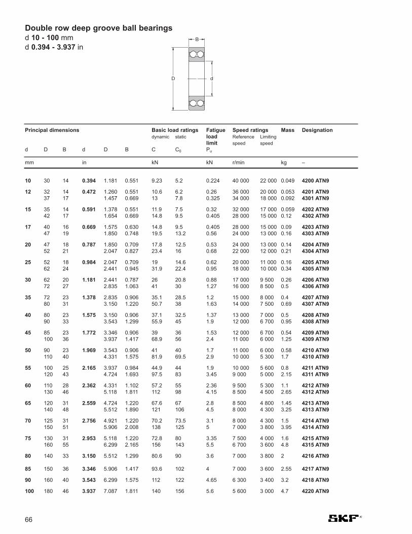
Principal dimensions Basic load ratings Fatigue Speed ratings Mass Designationdynamic static load Reference Limiting
limit speed speedd D B d D B C C0 Pu
mm in kN kN r/min kg –
66
10 30 14 0.394 1.181 0.551 9.23 5.2 0.224 40 000 22 000 0.049 4200 ATN9
12 32 14 0.472 1.260 0.551 10.6 6.2 0.26 36 000 20 000 0.053 4201 ATN937 17 1.457 0.669 13 7.8 0.325 34 000 18 000 0.092 4301 ATN9
15 35 14 0.591 1.378 0.551 11.9 7.5 0.32 32 000 17 000 0.059 4202 ATN942 17 1.654 0.669 14.8 9.5 0.405 28 000 15 000 0.12 4302 ATN9
17 40 16 0.669 1.575 0.630 14.8 9.5 0.405 28 000 15 000 0.09 4203 ATN947 19 1.850 0.748 19.5 13.2 0.56 24 000 13 000 0.16 4303 ATN9
20 47 18 0.787 1.850 0.709 17.8 12.5 0.53 24 000 13 000 0.14 4204 ATN952 21 2.047 0.827 23.4 16 0.68 22 000 12 000 0.21 4304 ATN9
25 52 18 0.984 2.047 0.709 19 14.6 0.62 20 000 11 000 0.16 4205 ATN962 24 2.441 0.945 31.9 22.4 0.95 18 000 10 000 0.34 4305 ATN9
30 62 20 1.181 2.441 0.787 26 20.8 0.88 17 000 9 500 0.26 4206 ATN972 27 2.835 1.063 41 30 1.27 16 000 8 500 0.5 4306 ATN9
35 72 23 1.378 2.835 0.906 35.1 28.5 1.2 15 000 8 000 0.4 4207 ATN980 31 3.150 1.220 50.7 38 1.63 14 000 7 500 0.69 4307 ATN9
40 80 23 1.575 3.150 0.906 37.1 32.5 1.37 13 000 7 000 0.5 4208 ATN990 33 3.543 1.299 55.9 45 1.9 12 000 6 700 0.95 4308 ATN9
45 85 23 1.772 3.346 0.906 39 36 1.53 12 000 6 700 0.54 4209 ATN9100 36 3.937 1.417 68.9 56 2.4 11 000 6 000 1.25 4309 ATN9
50 90 23 1.969 3.543 0.906 41 40 1.7 11 000 6 000 0.58 4210 ATN9110 40 4.331 1.575 81.9 69.5 2.9 10 000 5 300 1.7 4310 ATN9
55 100 25 2.165 3.937 0.984 44.9 44 1.9 10 000 5 600 0.8 4211 ATN9120 43 4.724 1.693 97.5 83 3.45 9 000 5 000 2.15 4311 ATN9
60 110 28 2.362 4.331 1.102 57.2 55 2.36 9 500 5 300 1.1 4212 ATN9130 46 5.118 1.811 112 98 4.15 8 500 4 500 2.65 4312 ATN9
65 120 31 2.559 4.724 1.220 67.6 67 2.8 8 500 4 800 1.45 4213 ATN9140 48 5.512 1.890 121 106 4.5 8 000 4 300 3.25 4313 ATN9
70 125 31 2.756 4.921 1.220 70.2 73.5 3.1 8 000 4 300 1.5 4214 ATN9150 51 5.906 2.008 138 125 5 7 000 3 800 3.95 4314 ATN9
75 130 31 2.953 5.118 1.220 72.8 80 3.35 7 500 4 000 1.6 4215 ATN9160 55 6.299 2.165 156 143 5.5 6 700 3 600 4.8 4315 ATN9
80 140 33 3.150 5.512 1.299 80.6 90 3.6 7 000 3 800 2 4216 ATN9
85 150 36 3.346 5.906 1.417 93.6 102 4 7 000 3 600 2.55 4217 ATN9
90 160 40 3.543 6.299 1.575 112 122 4.65 6 300 3 400 3.2 4218 ATN9
100 180 46 3.937 7.087 1.811 140 156 5.6 5 600 3 000 4.7 4220 ATN9
Double row deep groove ball bearingsd 10 - 100 mmd 0.394 - 3.937 in
D
B
d

Dimensions Limiting Mass Designationspeed
D B d D B d C C0 Pu d1 D1 r1,2
~ ~ Min
mm in kN kN r/min kg –
Single row cam rollersD 32 - 80 mm
D 1.260 - 3.150 in
D
B
d
67
32 9 10 1.260 0.354 0.394 4.62 2 0.085 14.8 23.4 0.6 12 000 0.041 361200 R
35 10 12 1.378 0.394 0.472 6.24 2.6 0.11 16.1 25.9 0.6 11 000 0.052 361201 R
40 11 15 1.575 0.433 0.591 7.02 3.2 0.134 19.2 29.7 0.6 9 500 0.074 361202 R
47 12 17 1.850 0.472 0.669 8.84 4.15 0.176 21.6 32.9 0.6 8 500 0.11 361203 R
52 14 20 2.047 0.551 0.787 11.4 5.4 0.228 26 38.7 1 7 500 0.16 361204 R
62 15 25 2.441 0.591 0.984 12.7 6.8 0.285 31.4 44.2 1 6 300 0.24 361205 R
72 16 30 2.835 0.630 1.181 17.4 9.3 0.4 37.6 52.1 1 5 300 0.34 361206 R
80 17 35 3.150 0.669 1.378 22.1 11.8 0.5 44 60.6 1.1 4 500 0.43 361207 R
Note: C3 clearance is standard

MRC Bore Outside Width Bore Outside Width Basic Radial Speed Ratings1)
Bearing Diameter Diameter Load Rating Open and Single andNumber d D B d D B Dynamic2) Static Shielded Double Sealed
Grease Oil Grease
mm in kN kN rpm rpm rpm
68
R-2 3.2 9.5 4.0 0.1250 0.3750 0.1562 0.312 0.120 75 000 91 000 52 000R-2-A 3.2 12.7 4.4 0.1250 0.5000 0.1719 0.312 0.120 75 000 91 000 52 000R-3 4.8 12.7 4.0 0.1875 0.5000 0.1562 0.956 0.490 57 000 69 000 40 000
R-4 6.4 15.9 5.0 0.2500 0.6250 0.1960 1.480 0.620 44 000 54 000 31 000R-4-A 6.4 19.1 5.6 0.2500 0.7500 0.2188 2.810 1.160 39 000 48 000 27 000R-6 9.5 22.2 5.6 0.3750 0.8750 0.2188 3.320 1.340 31 000 38 000 21 000
R-8 12.7 28.6 6.4 0.5000 1.1250 0.2500 5.070 2.400 24 000 29 000 16 000R-10 15.9 34.9 7.1 0.6250 1.3750 0.2812 6.050 3.250 18 000 22 000 13 000R-12 19.1 41.3 7.9 0.7500 1.6250 0.3125 9.360 5.100 16 000 19 000 11 000
R-14 22.2 47.6 9.5 0.8750 1.8750 0.3750 10.100 5.850 14 000 17 000 9 600R-16 25.4 50.8 9.5 1.0000 2.0000 0.3750 10.100 6.000 13 000 16 000 9 000R-18 28.6 54.0 9.5 1.1250 2.1250 0.3750 12.500 7.500 11 000 14 000 7 900
R-20 31.8 57.2 9.5 1.1250 2.2500 0.3750 14.000 9.300 11 000 13 000 7 500R-24 38.1 66.7 11.1 1.5000 2.6250 0.4375 16.800 11.800 9 000 11 000 6 200
MRC R series small inch-sized 3.2 - 38.1 mmd 0.1250 - 1.5000 in
R series bearings are single-row radial conrad-type bear-ings that are available in inch sizes for shafts from 1/8" to11/2" in diameter. Open, shielded, and sealed types areavailable, and many sizes are available in stainless steel.R series supplied with ABMA CN radial clearance unlessotherwise specified.
1) Listed values are for pressed steel or polyamide cage, ABEC-1.For phenolic composition cage, multiply by 1.66 for grease and 2.00 for oil. For machined bronze cage, multiply by 1.25 for grease and 1.50 for oil. Forphenolic composition cage, ABEC-5 or 7, multiply by 2.30 for grease and 2.80 for oil. The speed rating adjustment factors have been determinedthrough historical application and practice.
2) Rating for one million revolutions or 500 hours at 33 1/3 RPM.
D
B
d

Bearing Designation Principal Dimensions Basic dynamic Speed ratings MassNumber load rating Lubrication
grease oild D B d D B C
-Z -2Z in mm kN rpm kg
FOR REFERENCE ONLY
DO NOT USE IN NEW APPLICATIONS
RLS4A + + 0.5000 1.3125 0.3750 12.700 33.337 9.925 6.180 20 000 26 000 0.04
RLS 5 + + 0.6250 1.5625 0.4375 15.875 39.688 11.112 9.560 17 000 20 000 0.06
RLS 6 + + 0.7500 1.8750 0.5625 19.050 47.625 14.288 12.700 15 000 18 000 0.12
RLS 7 + + 0.8750 2.0000 0.5625 22.225 50.800 14.288 15.100 14 000 17 000 0.12
RLS 8 + + 1.0000 2.2500 0.6250 25.400 57.150 15.875 17.800 11 000 14 000 0.17
RLS 9 + + 1.1250 2.5000 0.6250 28.575 63.500 15.875 19.500 10 000 13 000 0.22
RLS 10 + + 1.2500 2.7500 0.6875 31.750 69.850 17.462 22.500 9 500 12 000 0.29
RLS 11 1.3750 3.0000 0.6875 34.925 76.200 17.462 25.500 9 000 11 000 0.35
RLS 12 1.5000 3.2500 0.7500 38.100 82.550 19.050 29.100 8 500 10 000 0.44
RLS 13 1.6250 3.5000 0.7500 41.275 88.900 19.050 32.500 7 500 9 000 0.51
RLS 14 1.7500 3.7500 0.8125 44.450 95.250 20.638 35.100 7 000 8 500 0.66
RLS 15 1.8750 4.0000 0.8125 47.625 101.600 20.638 43.600 6 300 7 500 0.74
RLS 16 2.0000 4.0000 0.8125 50.800 101.600 20.638 43.600 6 300 7 500 0.70
RLS 18 2.2500 4.5000 0.8750 57.150 114.300 22.225 52.700 6 000 7 000 0.96
RLS 20 2.5000 5.0000 0.9375 63.500 127.000 23.812 62.400 5 000 6 000 1.26
Single row deep groove ball bearingsSeries RLS
d 0.5000 - 2.5000 mmd 12.700 - 63.500 in
D
B
d
69

70
FOR REFERENCE ONLY
DO NOT USE IN NEW APPLICATIONS
RLS 22 2.7500 5.2500 0.9375 69.850 133.350 23.812 66.300 4 800 5 600 1.37
RLS 24 3.0000 5.7500 1.0625 76.200 146.050 26.988 72.800 4 500 5 300 1.85
RLS 26 3.2500 6.0000 1.0625 82.550 152.400 26.988 83.200 4 000 4 800 1.93
RLS 28 3.5000 6.5000 1.1250 88.900 165.100 28.575 95.600 3 800 4 500 2.38
RLS 30 3.7500 6.7500 1.1250 95.250 171.450 28.575 101.000 3 600 4 300 2.51
RLS 32 4.0000 7.2500 1.2500 101.600 184.150 31.750 108.000 3 400 4 000 3.25
RLS 34 4.2500 7.5000 1.2500 107.950 133.350 31.750 124.000 3 200 3 800 3.92
RLS 36 4.5000 8.0000 1.3125 114.300 203.200 33.338 130.000 3 000 3 600 4.76
RLS 38 4.7500 8.2500 1.3125 120.850 209.550 33.338 138.000 2 800 3 400 5.0
RLS 40 5.0000 9.0000 1.3750 127.000 228.600 34.925 148.000 2 600 3 200 6.5
RLS 44 5.5000 9.5000 1.3750 139.700 241.300 34.925 156.000 2 400 3 000 6.9
RLS 48 6.0000 10.5000 1.5625 152.400 266.700 39.688 172.000 2 000 2 600 9.8
Bearing Principal Dimensions Basic dynamic Speed ratings MassNumber load rating Lubrication
grease oild D B d D B C
in mm kN rpm rpm kg
Single row deep groove ball bearingsSeries RLSd 2.7500 - 6.0000 mmd 69.850 - 152.400 in
D
B
d

Bearing Principal Dimensions Basic dynamic Speed ratings MassNumber load rating Lubrication
grease oild D B d D B C
in mm kN rpm rpm kg
FOR REFERENCE ONLY
DO NOT USE IN NEW APPLICATIONS
RMS 4 0.5000 1.6250 0.6250 12.700 41.275 15.875 11.400 18 000 22 000 0.10
RMS 5 0.6250 1.8125 0.6250 15.875 46.038 15.875 13.800 16 000 19 000 0.12
RMS 6 0.7500 2.0000 0.6875 19.050 50.800 17.462 15.900 14 000 17 000 0.16
RMS 7 0.8750 2.2500 0.6875 22.225 57.150 17.462 18.600 12 000 15 000 0.21
RMS 8 1.0000 2.5000 0.7500 25.400 63.500 19.050 21.200 10 000 13 000 0.27
RMS 9 1.1250 2.8125 0.8125 28.575 71.438 20.638 27.000 9 500 12 000 0.37
RMS 10 1.2500 3.1250 0.8750 31.750 79.375 22.225 33.200 9 000 11 000 0.49
RMS 11 1.3750 3.5000 0.8750 34.925 88.900 22.225 40.300 8 000 9 500 0.63
RMS 12 1.5000 3.7500 0.9375 38.100 95.250 23.812 44.200 7 500 9 000 0.79
RMS 13 1.6250 4.0000 0.9375 41.275 101.600 23.812 52.700 6 700 8 000 0.91
RMS 14 1.7500 4.2500 1.0625 44.450 107.950 26.988 57.200 6 300 7 500 1.13
RMS 15 1.8750 4.5000 1.0625 47.625 114.300 26.988 66.300 6 000 7 000 1.24
RMS 16 2.0000 4.5000 1.0625 50.800 114.300 26.988 66.300 6 000 7 000 1.19
RMS 18 2.2500 5.0000 1.2500 57.150 127.000 31.750 76.100 5 300 6 300 1.70
RMS 20 2.5000 5.0000 1.2500 63.500 139.700 31.750 92.300 4 800 5 600 2.05
RMS 22 2.7500 6.2500 1.3750 69.850 158.750 34.925 104.000 4 300 5 000 2.97
RMS 24 3.0000 7.0000 1.5625 76.200 177.800 39.688 124.000 3 800 4 500 4.41
RMS 26 3.2500 7.5000 1.5625 82.550 190.500 39.688 133.000 3 400 4 000 5.00
RMS 28 3.5000 8.1250 1.7500 88.900 206.375 44.450 153.000 3 200 3 800 6.50
RMS 30 3.7500 8.2500 1.7500 95.250 209.550 44.450 153.000 3 200 3 800 6.50
RMS 32 4.0000 8.5000 1.7500 101.600 215.900 44.450 163.000 3 000 3 600 8.10
RMS 34 4.2500 8.7500 1.7500 107.950 222.250 44.450 174.000 2 800 3 400 8.50
RMS 36 4.5000 9.3750 2.0000 114.300 238.125 50.800 186.000 2 600 3 200 11.70
RMS 38 4.7500 10.0000 2.0000 120.850 254.000 50.800 195.000 2 400 3 000 12.70
RMS 40 5.0000 10.0000 2.0000 127.000 254.000 50.800 195.000 2 400 3 000 12.10
RMS 44 M 5.5000 11.0000 2.0000 139.700 279.400 50.800 212.000 2 000 2 600 -
Single row deep groove ball bearingsSeries RMS
d 0.5000 - 5.5000 mmd 12.700 - 139.700 in
D
B
d
71

MRC Bore Outside Width Bore Outside Width Basic Radial Speed Ratings1)
Bearing Diameter Diameter Load Rating Open and Single andNumber d D B d D B Dynamic2) Static Shielded Double Sealed
Grease Oil Grease
mm in kN kN rpm rpm rpm
72
38-FFC 8 22 11.99 0.3150 0.8661 0.472 3.25 1.37 36 000 43 000 23 000200-SFFC 10 30 14.29 0.3937 1.1811 9/16 5.07 2.40 24 000 30 000 17 000201-SFFC 12 32 15.88 0.4724 1.2598 5/8 6.76 3.00 22 000 28 000 15 000
202-SFFC 15 35 15.88 0.5906 1.3780 5/8 7.61 3.75 19 000 24 000 13 000203-SFFC 17 40 17.46 0.6693 1.5748 11/16 9.56 4.50 17 000 20 000 12 000204-SFFC 20 47 20.64 0.7874 1.8504 13/16 13.00 6.70 15 000 18 000 10 000
205-SFFC 25 52 20.64 0.9843 2.0472 13/16 15.10 8.15 12 000 15 000 8 500206-SFFC 30 62 23.81 1.1811 2.4409 15/16 20.80 11.40 10 000 13 000 7 500207-SFFC 35 72 26.99 1.3780 2.8346 11/16 26.50 15.30 9 000 11 000 6 300
208-SFFC 40 80 30.16 1.5748 3.1496 13/16 32.50 20.00 8 500 10 000 5 600209-SFFC 45 85 30.16 1.7717 3.3465 13/16 36.40 22.80 7 500 9 000 5 000210-SFFC 50 90 30.16 1.9685 3.5433 13/16 35.10 23.20 7 000 8 500 4 800
211-SFFC 55 100 33.34 2.1654 3.9370 15/16 39.70 29.00 6 300 7 500 4 300213-SFFC 65 120 38.10 2.5591 4.7244 11/2 62.40 44.00 5 300 6 300 3 600214-SFFC 70 125 39.69 2.7559 4.9213 19/16 62.40 44.00 5 000 6 000 3 400216-SFFC 80 140 44.45 3.1496 5.5118 13/4 78.00 53.00 4 500 5 300 3 000
304-SFFC 20 52 22.23 0.7874 2.0472 7/8 15.90 7.80 13 000 16 000 9 500305-SFFC 25 62 25.40 0.9843 2.4409 1 21.00 11.00 11 000 14 000 7 500306-SFFC 30 72 30.16 1.1811 2.8346 13/16 29.60 16.60 9 000 11 000 6 300
307-SFFC 35 80 34.93 1.3780 3.1496 13/8 36.40 20.00 8 500 10 000 6 000308-SFFC 40 90 36.51 1.5748 3.5433 17/16 44.20 26.00 7 500 9 000 5 000309-SFFC 45 100 39.69 1.7717 3.9370 19/16 52.00 30.00 6 700 8 000 4 500
310-SFFC 50 110 44.45 1.9685 4.3307 13/4 61.80 38.00 6 300 7 500 4 300311-SFFC 55 120 49.21 2.1654 4.7244 115/16 71.50 45.00 5 600 6 700 3 800312-SFFC 60 130 53.98 2.3622 5.1181 21/8 81.90 52.00 5 000 6 000 3 400
313-SFFC 65 140 58.74 2.5591 5.5118 2 5/16 92.30 60.00 4 800 5 600 3 200314-SFFC 70 150 63.50 2.7559 5.9055 21/2 104.00 68.00 4 500 5 300 3 000315-SFFC 75 160 68.26 2.9528 6.2992 211/16 124.00 85.00 4 300 5 000 2 800
316-SFFC 80 170 68.26 3.1496 6.6929 211/16 133.00 95.00 3 800 4 500 2 600317-SFFC 85 180 73.03 3.3465 7.0866 27/8 133.00 96.50 3 600 4 300 2 400318-SFFC 90 190 73.03 3.5433 7.4803 27/8 143.00 108.00 3 400 4 000 2 400
320-SFFC 100 215 82.55 3.9370 8.4646 31/4 182.00 150.00 3 000 3 600 2 100
MRC Cartridge-type bearings typesSFFC, SZZC, SLLCd 8 - 100 mmd 0.3150 - 3.9370 in
Cartridge-type bearings have an extra large grease cham-ber packed with high quality lubricant. For applicationswhere space for a lubrication system is limited or conditionsdemand a larger grease supply inside bearing.Bearings designated SFFC have non-removable metal shields.Many sizes are available with removable shields (SLLC) or syntheticrubber seals (SZZC).
1) Listed values are for pressed steel or polyamide cage, ABEC-1.The values have been determined through historical application and practice.
2) Rating for one million revolutions or 500 hours at 33 1/3 RPM.
D
B
d

73
7200 BE CB Y HC5
12
34
Angular Contact Ball Bearings
1. Design
A Non-filling slot (Conrad type -3000, 5000 series) MRC. C.
B 40° contact angle
BE 40° contact angle, high capacity, all ISO corners
D Split inner ring (3300 series)
D MRC 29° contact angle, 1/2 pair,duplex
DU MRC 29° contact angle andground for duplex mounting andzero preload/ clearance
E Filling slot (Max type - 5000series) MRC. M.
FF 2 Shields on MRC DRACBB
NR Snap ring (3300,5000 series)
N2 Locating slot (QJ Series)
R MRC single row with 15° contactangle
RD MRC single row for duplexmounting and 15° contact angle
2RS1 Rubber seals on both sides
ZZ 2 rubber seals on MRC DRACBB
2Z Metal shields on both sides(5000 series)
2. Clearance
C2 Axial clearance tighter than normal (3000,5000 and QJ series)
C3 Axial clearance greater thannormal (3000, 5000 and QJseries)
7000 Series clearance*
CA Modified for duplex mountingwith axial clearance < normal
CB Modified for duplex mountingwith normal axial clearance
CC Modified for duplex mountingwith axial clearance > normal
CN Normal clearance (3000, 5000series) no symbol shown
GA Modified for duplex mountingwith light preload
GB Modified for duplex mountingwith medium preload
GC Modified for duplex mountingwith heavy preload
G... Special preload, value in daN
*If the above symbols from CA to G.. arenot shown the bearing is not modified forduplex mounting
3. Cage Design
J Pressed steel cage, ball centred.
M Machined brass cage, ballcentred
P Fibreglass reinforced polyamide,ball centred
Y Press brass cage
4. Special Features
HC4 Full ceramic bearing
HC5 Ceramic ball set
5. Lubrication
MT33 Medium temperature Lithiumgrease, 74 cSt @ 40°C, range -30°C to + 120°C
GJN Di-urea hi-temp, 115cSt @ 40°C, range -40°C to +150°C

Single Row ACBB Double Row ACBB Four-Point Contact ACBB
Boundary In accordance with In accordance with In accordance with Dimensions ISO 15-1998 ISO 15-1998 ISO 15-1998
Tolerances ABEC 3 (P6) ABEC 3 (P6)* ABEC 3 (P6)SKF Explorer P5running P6 boundary
Heat Stabilization 257°F (125°C) 257°F (125°C) 302°F (150°C)SKF Explorer 150°C SKF Explorer 150°C
Misalignment None - contact SKF None - contact SKF None - contact SKF
Cage Materials Polyamide (P)* Polyamide (TN9) Machined Brass (M, MA)Machined Brass (M)* Limited sizes, pressedPressed Steel1) J steel.Pressed brass1) (Y)
Axial Load - max 1.4 x C0 for single or 0.7 x C0 Conrad 0.7 x C0
tandem mounted Fa /Fr < 0.3bearings0.7 x C0 for duplexmounting
Seals, shields Not available 2RS1- Nitrile rubber Not available2Z - Steel shields
*SKF Explorer types1) Non-Explorer
74
Technical Features
Double Row Angular Contact
Ball Bearing(data tables on page 91)
Four-Point Angular Contact
Ball Bearing(data tables on page 95)
Single Row Angular Contact
Ball Bearing(data tables on page 78)
Angular contact ball bearings

75
Bore Preloaddiameter
GA GB GCdover incl. min max min max max max min max min max min max min max min max min max min max min max
mm µm in N lbf µm in N lbf µm in N lbf
10 18 4 -4 0.0002 -0.0002 80 18 -2 -10 -0.0001 -0.0004 30 330 7 74 -8 -16 -0.0003 -0.0006 230 660 52 14918 30 4 -4 0.0002 -0.0002 120 27 -2 -10 -0.0001 -0.0004 40 480 9 108 -8 -16 -0.0003 -0.0006 340 970 76 21830 50 4 -4 0.0002 -0.0002 160 36 -2 -10 -0.0001 -0.0004 60 630 13 142 -8 -16 -0.0003 -0.0006 450 1 280 101 288
50 80 6 -6 0.0002 -0.0002 380 86 -3 -15 -0.0001 -0.0006 140 1 500 31 338 -12 -24 -0.0005 -0.0009 1 080 3 050 243 68680 120 6 -6 0.0002 -0.0002 410 92 -3 -15 -0.0001 -0.0006 150 1 600 34 360 -12 -24 -0.0005 -0.0009 1 150 3 250 259 731120 180 6 -6 0.0002 -0.0002 540 122 -3 -15 -0.0001 -0.0006 200 2 150 45 484 -12 -24 -0.0005 -0.0009 1 500 4 300 337 968
180 250 8 -8 0.0003 -0.0003 940 212 -4 -20 -0.0002 -0.0008 330 3 700 74 833 -16 -32 -0.0006 -0.0013 2 650 7 500 596 1 688250 315 8 -8 0.0003 -0.0003 1 080 243 -4 -20 -0.0002 -0.0008 380 4 250 85 956 -16 -32 -0.0006 -0.0013 3 000 8 600 674 1 935
Bore Axial internal clearancediameter
CA CB CCd
over incl. min max min max min max min max min max min maxmm µm in µm in µm in
- 10 4 12 0.0002 0.0005 14 22 0.0006 0.0009 22 30 0.0009 0.001210 18 5 13 0.0002 0.0005 15 23 0.0006 0.0009 24 32 0.0009 0.001318 30 7 15 0.0003 0.0006 18 26 0.0007 0.0010 32 40 0.0013 0.0016
30 50 9 17 0.0004 0.0007 22 30 0.0009 0.0012 40 48 0.0016 0.001950 80 11 23 0.0004 0.0009 26 38 0.0010 0.0015 48 60 0.0019 0.002480 120 14 26 0.0006 0.0010 32 44 0.0013 0.0017 55 67 0.0022 0.0026
120 180 17 29 0.0007 0.0011 35 47 0.0014 0.0019 62 74 0.0024 0.0029180 250 21 37 0.0008 0.0015 45 61 0.0018 0.0024 74 90 0.0029 0.0035250 315 26 42 0.0010 0.0017 52 68 0.0020 0.0027 90 106 0.0035 0.0042
InternalClearanceAxial internal clearance singlerow angular contact ballbearingsInternal clearance in a single rowangular contact ball bearing is onlyobtained after mounting and isdependent on adjustment against asecond bearing that provides axiallocation in the opposite direction.
Bearings for universal pairing (suffix CB)are the standard SKF bearings for pairedmounting in random order (back-to-back,face-to-face or tandem). Bearings can besupplied with smaller axial internalclearance (suffix CA) or larger (suffix CC)or with preload (suffixes GA, GB andGC) for universal pairing.
Bearings identified by suffix CA, CB orCC can be mounted immediatelyadjacent to each other in any order andtwo or more bearings may be used.Bearings with preload of the GA, GB andGC designs can only be arranged inpairs, otherwise the preload will increase.
The values of axial internal clearancefor the classes CA, CB and CC can befound in table 1. They are valid forbearings arranged back-to-back orface-to-face before mounting and underzero measuring load. Preload valuesfor classes GA, GB and GC are givenin table 1a. Table 2 shows aconversion from the old preloadsuffixes to the current suffix.
Radial clearance [~=] 0.85 axial clearance.
Table 1 Unmounted axial internal clearance of single row angular contact ballbearings of series 72B (E), 73B (E) and 74B (B) when arranged in randompairs (back-to-back or face-to-face)
Table 1a Unmounted preload of single row angular contact ball bearings of series 72B (E), 73B (E) and 74 (B) when arranged in random pairs (back-to-back or face-to-face)
Angular contact ball bearings
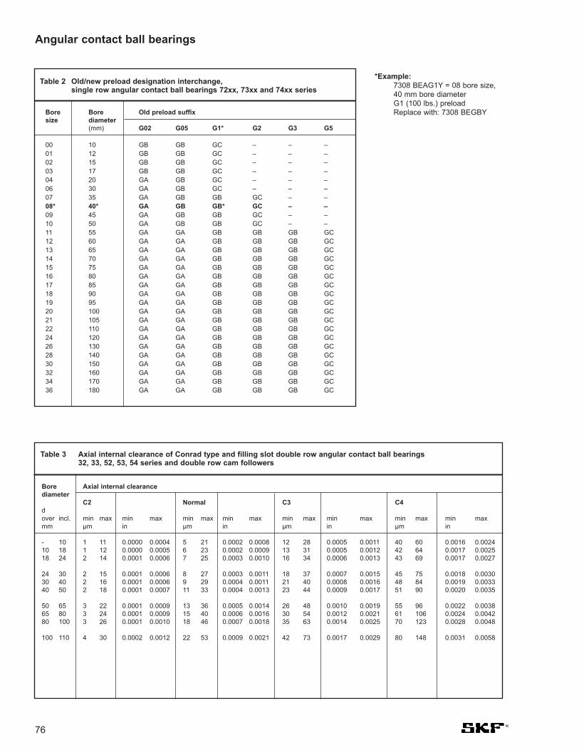
Bore Bore Old preload suffixsize diameter
(mm) G02 G05 G1* G2 G3 G5
00 10 GB GB GC – – –01 12 GB GB GC – – –02 15 GB GB GC – – –03 17 GB GB GC – – –04 20 GA GB GC – – –06 30 GA GB GC – – –07 35 GA GB GB GC – –08* 40* GA GB GB* GC – –09 45 GA GB GB GC – –10 50 GA GB GB GC – –11 55 GA GA GB GB GB GC12 60 GA GA GB GB GB GC13 65 GA GA GB GB GB GC14 70 GA GA GB GB GB GC15 75 GA GA GB GB GB GC16 80 GA GA GB GB GB GC17 85 GA GA GB GB GB GC18 90 GA GA GB GB GB GC19 95 GA GA GB GB GB GC20 100 GA GA GB GB GB GC21 105 GA GA GB GB GB GC22 110 GA GA GB GB GB GC24 120 GA GA GB GB GB GC26 130 GA GA GB GB GB GC28 140 GA GA GB GB GB GC30 150 GA GA GB GB GB GC32 160 GA GA GB GB GB GC34 170 GA GA GB GB GB GC36 180 GA GA GB GB GB GC
76
Table 2 Old/new preload designation interchange,single row angular contact ball bearings 72xx, 73xx and 74xx series
Bore Axial internal clearancediameter
C2 Normal C3 C4dover incl. min max min max min max min max min max min max min max min maxmm µm in µm in µm in µm in
- 10 1 11 0.0000 0.0004 5 21 0.0002 0.0008 12 28 0.0005 0.0011 40 60 0.0016 0.002410 18 1 12 0.0000 0.0005 6 23 0.0002 0.0009 13 31 0.0005 0.0012 42 64 0.0017 0.002518 24 2 14 0.0001 0.0006 7 25 0.0003 0.0010 16 34 0.0006 0.0013 43 69 0.0017 0.0027
24 30 2 15 0.0001 0.0006 8 27 0.0003 0.0011 18 37 0.0007 0.0015 45 75 0.0018 0.003030 40 2 16 0.0001 0.0006 9 29 0.0004 0.0011 21 40 0.0008 0.0016 48 84 0.0019 0.003340 50 2 18 0.0001 0.0007 11 33 0.0004 0.0013 23 44 0.0009 0.0017 51 90 0.0020 0.0035
50 65 3 22 0.0001 0.0009 13 36 0.0005 0.0014 26 48 0.0010 0.0019 55 96 0.0022 0.003865 80 3 24 0.0001 0.0009 15 40 0.0006 0.0016 30 54 0.0012 0.0021 61 106 0.0024 0.004280 100 3 26 0.0001 0.0010 18 46 0.0007 0.0018 35 63 0.0014 0.0025 70 123 0.0028 0.0048
100 110 4 30 0.0002 0.0012 22 53 0.0009 0.0021 42 73 0.0017 0.0029 80 148 0.0031 0.0058
Table 3 Axial internal clearance of Conrad type and filling slot double row angular contact ball bearings 32, 33, 52, 53, 54 series and double row cam followers
Angular contact ball bearings
*Example: 7308 BEAG1Y = 08 bore size,40 mm bore diameterG1 (100 lbs.) preloadReplace with: 7308 BEGBY

77
Bore Axial internal clearancediameterd C2 Normal C3 C4
over incl. over incl. min max min max min max min max min max min max min max min maxmm in µm in µm in µm in µm in
Table 4 Axial internal clearance of four-point contact ball bearings
10 17 0.3937 0.6693 15 55 0.0006 0.0022 45 85 0.0018 0.0033 75 125 0.0030 0.0049 115 165 0.0045 0.006518 40 0.6693 1.5748 26 66 0.0010 0.0026 56 106 0.0022 0.0042 96 146 0.0038 0.0057 136 186 0.0054 0.007340 60 1.5748 2.3622 36 86 0.0014 0.0034 76 126 0.0030 0.0050 116 166 0.0046 0.0065 156 206 0.0061 0.0081
60 80 2.3622 3.1496 46 96 0.0018 0.0038 86 136 0.0034 0.0054 126 176 0.0050 0.0069 166 226 0.0065 0.008980 100 3.1496 3.9370 56 106 0.0022 0.0042 96 156 0.0038 0.0061 136 196 0.0054 0.0077 186 246 0.0073 0.0097100 140 3.9370 5.5118 66 126 0.0026 0.005 116 176 0.0046 0.0069 156 216 0.0061 0.0085 206 266 0.0081 0.0105
140 180 5.5118 7.0866 76 156 0.0030 0.0061 136 196 0.0054 0.0077 176 246 0.0069 0.0097 226 296 0.0089 0.0116180 220 7.0866 8.6614 96 176 0.0038 0.0069 156 226 0.0061 0.0089 206 276 0.0081 0.0109 256 326 0.0101 0.0128
Double row angular contact ballbearingsBasic design bearings in the 32 A and 33 A series shown in the product table aswell as the corresponding sealed bearingsto 2Z and 2RS1 design are identical to thecorresponding bearings in the 52 and 53series for the North American market. Theyhave the same performance characteristicsand dimensional features (except for thewidth of size 5200). However, the sealedbearings are filled with a different grease.Bearings in the 52 and 53 series use amineral oil based high-temperature greasewith di-urea thickener. The operatingtemperature range of this grease is -30 to+175°C. The base oil viscosity is 115mm2/s at 40°C and 12 mm2/s at 100°C.
For 3200 and 3300 series, the grease hasa lithium thickener with a mineral oil base.The operating temperature is -30°C to+120°C, with a base oil viscosity of74mm2/s at 40°C
a b c
Angular contact ball bearings
open shielded split inner ring

78
Single row angular contact ball bearingsd 10 - 35 mmd 0.394 - 1.378 in
10 30 9 0.394 1.181 0.354 7.02 3.35 0.14 30 000 30 000 0.03 7200 BECBP 7200 BEP
12 32 10 0.472 1.260 0.394 7.61 3.8 0.16 26 000 26 000 0.036 7201 BECBP 7201 BEP37 12 1.457 0.472 10.6 5 0.208 24 000 24 000 0.063 – 7301 BEP
15 35 11 0.591 1.378 0.433 8.84 4.8 0.204 24 000 24 000 0.045 7202 BECBP 7202 BEP42 13 1.654 0.512 13 6.7 0.28 20 000 20 000 0.081 7302 BECBP 7302 BEP
17 40 12 0.669 1.575 0.472 11 5.85 0.25 22 000 22 000 0.064 * 7203 BECBP –40 12 1.575 0.472 10.4 5.5 0.236 20 000 20 000 0.064 – 7203 BEP40 12 1.575 0.472 11.1 6.1 0.26 20 000 20 000 0.064 – 7203 BEY40 12 1.575 0.472 11 5.85 0.25 22 000 22 000 0.07 * 7203 BECBM –47 14 1.850 0.551 15.9 8.3 0.355 19 000 19 000 0.11 7303 BECBP 7303 BEP
20 47 14 0.787 1.850 0.551 14 8.3 0.355 18 000 18 000 0.11 7204 BECBP 7204 BEP47 14 1.850 0.551 14 8.3 0.355 18 000 18 000 0.11 7204 BECBY –47 14 1.850 0.551 13.3 7.65 0.325 18 000 19 000 0.11 7204 BECBM –52 15 2.047 0.591 19 10 0.425 18 000 18 000 0.14 * 7304 BECBP –52 15 2.047 0.591 17.4 9.5 0.4 16 000 16 000 0.14 – 7304 BEP52 15 2.047 0.591 19 10.4 0.44 16 000 16 000 0.15 7304 BECBY 7304 BEY52 15 2.047 0.591 19 10 0.425 18 000 18 000 0.15 * 7304 BECBM –
25 52 15 0.984 2.047 0.591 15.6 10 0.43 17 000 17 000 0.13 * 7205 BECBP –52 15 2.047 0.591 14.8 9.3 0.4 15 000 15 000 0.13 – 7205 BEP52 15 2.047 0.591 15.6 10.2 0.43 15 000 15 000 0.13 7205 BECBY 7205 BEY52 15 2.047 0.591 15.6 10 0.43 17 000 17 000 0.14 * 7205 BECBM –62 17 2.441 0.669 26.5 15.3 0.655 15 000 15 000 0.23 * 7305 BECBP –62 17 2.441 0.669 24.2 14 0.6 14 000 14 000 0.23 – 7305 BEP62 17 2.441 0.669 26 15.6 0.655 14 000 14 000 0.24 7305 BECBY 7305 BEY62 17 2.441 0.669 26.5 15.3 0.655 15 000 15 000 0.24 * 7305 BECBM –
30 62 16 1.181 2.441 0.630 24 15.6 0.655 14 000 14 000 0.19 * 7206 BECBP –62 16 2.441 0.630 22.5 14.3 0.61 13 000 13 000 0.19 – 7206 BEP62 16 2.441 0.630 23.8 15.6 0.655 13 000 13 000 0.21 7206 BECBY 7206 BEY62 16 2.441 0.630 24 15.6 0.655 14 000 14 000 0.21 * 7206 BECBM –72 19 2.835 0.748 35.5 21.2 0.9 13 000 13 000 0.33 * 7306 BECBP –72 19 2.835 0.748 32.5 19.3 0.815 12 000 12 000 0.33 – 7306 BEP72 19 2.835 0.748 34.5 21.2 0.9 12 000 12 000 0.37 7306 BECBY 7306 BEY72 19 2.835 0.748 35.5 21.2 0.9 13 000 13 000 0.37 * 7306 BECBM –
35 72 17 1.378 2.835 0.669 31 20.8 0.88 12 000 12 000 0.28 * 7207 BECBP –72 17 2.835 0.669 29.1 19 0.815 11 000 11 000 0.28 – 7207 BEP72 17 2.835 0.669 30.7 20.8 0.88 11 000 11 000 0.3 7207 BECBY 7207 BEY72 17 2.835 0.669 31 20.8 0.88 12 000 12 000 0.3 * 7207 BECBM –80 21 3.150 0.827 41.5 26.5 1.14 11 000 11 000 0.45 * 7307 BECBP –80 21 3.150 0.827 39 24.5 1.04 10 000 10 000 0.45 – 7307 BEP80 21 3.150 0.827 39 24.5 1.04 10 000 10 000 0.49 7307 BECBY 7307 BEY80 21 3.150 0.827 41.5 26.5 1.14 11 000 11 000 0.49 * 7307 BECBM –
D
B
d
* SKF Explorer bearing
Principal dimensions Basic load ratings Fatigue Speed ratings Mass Designationsdynamic static load Reference Limiting Universally Basic
limit speed speed matchable designd D B d D B C C0 Pu bearing bearing
mm in kN kN r/min kg –
40° contact angle

79
40 80 18 1.575 3.150 0.709 36.5 26 1.1 11 000 11 000 0.37 * 7208 BECBP –80 18 3.150 0.709 34.5 24 1.02 10 000 10 000 0.37 – 7208 BEP80 18 3.150 0.709 36.4 26 1.1 10 000 10 000 0.38 7208 BECBY 7208 BEY80 18 3.150 0.709 36.5 26 1.1 11 000 11 000 0.39 * 7208 BECBM –80 18 3.150 0.709 34.5 24 1.02 10 000 10 000 0.39 – 7208 BEM90 23 3.543 0.906 50 32.5 1.37 10 000 10 000 0.61 * 7308 BECBP –90 23 3.543 0.906 46.2 30.5 1.13 9 000 9 000 0.61 – 7308 BEP90 23 3.543 0.906 49.4 33.5 1.4 9 000 9 000 0.64 7308 BECBY 7308 BEY90 23 3.543 0.906 50 32.5 1.37 10 000 10 000 0.68 * 7308 BECBM –
45 85 19 1.772 3.346 0.748 38 28.5 1.22 10 000 10 000 0.42 * 7209 BECBP –85 19 3.346 0.748 35.8 26 1.12 9 000 9 000 0.42 – 7209 BEP85 19 3.346 0.748 37.7 28 1.2 9 000 9 000 0.43 7209 BECBY 7209 BEY85 19 3.346 0.748 38 28.5 1.22 10 000 10 000 0.44 * 7209 BECBM –100 25 3.937 0.984 61 40.5 1.73 9 000 9 000 0.82 * 7309 BECBP –100 25 3.937 0.984 55.9 37.5 1.73 8 000 8 000 0.82 – 7309 BEP100 25 3.937 0.984 60.5 41.5 1.73 8 000 8 000 0.86 7309 BECBY 7309 BEY100 25 3.937 0.984 61 40.5 1.73 9 000 9 000 0.9 * 7309 BECBM –
50 90 20 1.969 3.543 0.787 40 31 1.32 9 000 9 000 0.47 * 7210 BECBP –90 20 3.543 0.787 37.7 28.5 1.22 8 500 8 500 0.47 – 7210 BEP90 20 3.543 0.787 39 30.5 1.29 8 500 8 500 0.47 7210 BECBY 7210 BEY90 20 3.543 0.787 40 31 1.32 9 000 9 000 0.51 * 7210 BECBM –110 27 4.331 1.063 75 51 2.16 8 000 8 000 1.04 * 7310 BECBP –110 27 4.331 1.063 68.9 47.5 2 7 500 7 500 1.04 – 7310 BEP110 27 4.331 1.063 74.1 51 2.2 7 500 7 500 1.13 7310 BECBY 7310 BEY110 27 4.331 1.063 75 51 2.16 8 000 8 000 1.16 * 7310 BECBM –
55 100 21 2.165 3.937 0.827 48.8 38 1.63 7 500 7 500 0.62 7211 BECBP 7211 BEP100 21 3.937 0.827 48.8 38 1.63 7 500 7 500 0.62 7211 BECBY 7211 BEY100 21 3.937 0.827 46.2 36 1.53 7 500 8 000 0.66 7211 BECBM –
55 120 29 2.165 4.724 1.142 85 60 2.55 7 000 7 000 1.34 * 7311 BECBP –120 29 4.724 1.142 79.3 55 2.32 6 700 6 700 1.34 – 7311 BEP120 29 4.724 1.142 85.2 60 2.55 6 700 6 700 1.48 7311 BECBY 7311 BEY120 29 4.724 1.142 85 60 2.55 7 000 7 000 1.49 * 7311 BECBM –
60 110 22 2.362 4.331 0.866 61 50 2.12 7 500 7 500 0.78 * 7212 BECBP –110 22 4.331 0.866 57.2 45.5 1.93 7 000 7 000 0.78 – 7212 BEP110 22 4.331 0.866 57.2 45.5 1.93 7 000 7 000 0.83 7212 BECBY 7212 BEY110 22 4.331 0.866 61 50 2.12 7 500 7 500 0.85 * 7212 BECBM –130 31 5.118 1.220 104 76.5 3.2 6 700 6 700 1.71 * 7312 BECBP –130 31 5.118 1.220 95.6 69.5 3 6 000 6 000 1.71 – 7312 BEP130 31 5.118 1.220 95.6 69.5 3 6 000 6 000 1.75 7312 BECBY 7312 BEY130 31 5.118 1.220 104 76.5 3.2 6 700 6 700 1.88 * 7312 BECBM –130 31 5.118 1.220 95.6 69.5 3 6 000 6 300 1.88 – 7312 BEM
Single row angular contact ball bearingsd 40 - 60 mm
d 1.575 - 2.362 in
* SKF Explorer bearing
Principal dimensions Basic load ratings Fatigue Speed ratings Mass Designationsdynamic static load Reference Limiting Universally Basic
limit speed speed matchable designd D B d D B C C0 Pu bearing bearing
mm in kN kN r/min kg –

80
Single row angular contact ball bearingsd 65 - 90 mmd 2.559 - 3.543 in
65 120 23 2.559 4.724 0.906 66.3 54 2.28 6 300 6 300 1 7213 BECBP 7213 BEP120 23 4.724 0.906 66.3 54 2.28 6 300 6 300 1 7213 BECBY 7213 BEY120 23 4.724 0.906 66.3 54 2.28 6 300 6 700 1.1 7213 BECBM –140 33 5.512 1.299 116 86.5 3.65 6 300 6 300 2.1 * 7313 BECBP –140 33 5.512 1.299 108 80 3.35 5 600 5 600 2.15 7313 BECBY 7313 BEP140 33 5.512 1.299 116 86.5 3.65 6 300 6 300 2.31 * 7313 BECBM –
70 125 24 2.756 4.921 0.945 75 64 2.7 6 300 6 300 1.1 * 7214 BECBP –125 24 4.921 0.945 71.5 60 2.5 6 000 6 000 1.1 7214 BECBY 7214 BEP125 24 4.921 0.945 72 60 2.55 6 300 6 300 1.18 * 7214 BECBM –150 35 5.906 1.378 127 98 3.9 5 600 5 600 2.55 * 7314 BECBP –150 35 5.906 1.378 119 90 3.65 5 300 5 300 2.67 7314 BECBY 7314 BEP150 35 5.906 1.378 127 98 3.9 5 600 5 600 2.83 * 7314 BECBM –
75 130 25 2.953 5.118 0.984 72.8 64 2.65 5 600 5 600 1.18 7215 BECBP 7215 BEP130 25 5.118 0.984 72.8 64 2.65 5 600 5 600 1.26 7215 BECBY –130 25 5.118 0.984 70.2 60 2.5 5 600 6 000 1.29 7215 BECBM –160 37 6.299 1.457 132 104 4.15 5 300 5 300 3.06 * 7315 BECBP –160 37 6.299 1.457 125 98 3.8 5 000 5 000 3.06 – 7315 BEP160 37 6.299 1.457 133 106 4.15 5 000 5 000 3.2 7315 BECBY –160 37 6.299 1.457 132 104 4.15 5 300 5 300 3.26 * 7315 BECBM –
80 140 26 3.150 5.512 1.024 80.6 69.5 2.8 5 300 5 300 1.43 7216 BECBP 7216 BEP140 26 5.512 1.024 83.2 73.5 3 5 300 5 300 1.58 7216 BECBY –140 26 5.512 1.024 85 75 3.05 5 600 5 600 1.59 * 7216 BECBM –
80 170 39 3.150 6.693 1.535 143 118 4.5 5 000 5 000 3.64 * 7316 BECBP –170 39 6.693 1.535 135 110 4.15 4 500 4 500 3.64 – 7316 BEP170 39 6.693 1.535 143 118 4.5 4 500 4 500 3.7 7316 BECBY 7316 BEY170 39 6.693 1.535 143 118 4.5 5 000 5 000 4.03 * 7316 BECBM –170 39 6.693 1.535 135 110 4.15 4 500 4 800 3.8 – 7316 BEM
85 150 28 3.346 5.906 1.102 95.6 83 3.25 5 000 5 000 1.83 7217 BECBP 7217 BEP150 28 5.906 1.102 95.6 83 3.25 5 000 5 000 1.83 7217 BECBY –150 28 5.906 1.102 95.6 83 3.25 5 000 5 300 1.99 7217 BECBM –180 41 7.087 1.614 156 132 4.9 4 800 4 800 4.26 * 7317 BECBP –180 41 7.087 1.614 146 112 4.5 4 300 4 300 4.26 – 7317 BEP180 41 7.087 1.614 153 132 4.9 4 300 4 300 4.59 7317 BECBY –180 41 7.087 1.614 156 132 4.9 4 800 4 800 4.74 * 7317 BECBM –180 41 7.087 1.614 146 112 4.5 4 300 4 500 4.74 – 7317 BEM
90 160 30 3.543 6.299 1.181 108 96.5 3.65 4 500 4 500 2.12 7218 BECBP 7218 BEP160 30 6.299 1.181 108 96.5 3.65 4 500 4 500 2.34 7218 BECBY –160 30 6.299 1.181 108 96.5 3.65 4 500 4 800 2.41 7218 BECBM –190 43 7.480 1.693 166 146 5.3 4 500 4 500 4.98 * 7318 BECBP –190 43 7.480 1.693 156 134 4.8 4 000 4 000 4.98 – 7318 BEP190 43 7.480 1.693 165 146 5.2 4 000 4 000 5.22 7318 BECBY –190 43 7.480 1.693 166 146 5.3 4 500 4 500 5.53 * 7318 BECBM –190 43 7.480 1.693 156 134 4.8 4 000 4 300 5.53 – 7318 BEM
D
B
d
* SKF Explorer bearing
Principal dimensions Basic load ratings Fatigue Speed ratings Mass Designationsdynamic static load Reference Limiting Universally Basic
limit speed speed matchable designd D B d D B C C0 Pu bearing bearing
mm in kN kN r/min kg –
40° contact angle

81
95 170 32 3.740 6.693 1.260 124 108 4 4 300 4 300 2.68 7219 BECBP 7219 BEP170 32 6.693 1.260 124 108 4 4 300 4 300 2.82 7219 BECBY –170 32 6.693 1.260 129 118 4.4 4 800 4 800 2.95 * 7219 BECBM –200 45 7.874 1.772 180 163 5.7 4 300 4 300 5.77 * 7319 BECBP –200 45 7.874 1.772 168 150 5.2 3 800 3 800 5.77 – 7319 BEP200 45 7.874 1.772 178 163 5.6 3 800 3 800 6.17 7319 BECBY –200 45 7.874 1.772 180 163 5.7 4 300 4 300 6.41 * 7319 BECBM –200 45 7.874 1.772 168 150 5.2 3 800 4 000 6.41 – 7319 BEM
100 180 34 3.937 7.087 1.339 135 122 4.4 4 000 4 000 3.29 7220 BECBP 7220 BEP180 34 7.087 1.339 135 122 4.4 4 000 4 000 3.38 7220 BECBY 7220 BEY180 34 7.087 1.339 135 122 4.4 4 000 4 300 3.61 7220 BECBM –215 47 8.465 1.850 216 208 6.95 4 000 4 000 7.17 * 7320 BECBP –215 47 8.465 1.850 203 190 6.4 3 600 3 600 7.17 – 7320 BEP215 47 8.465 1.850 203 190 6.4 3 600 3 600 7.15 7320 BECBY 7320 BEY215 47 8.465 1.850 216 208 6.95 4 000 4 000 8 * 7320 BECBM –215 47 8.465 1.850 203 190 6.4 3 600 3 800 8 – 7320 BEM
105 190 36 4.134 7.480 1.417 148 137 4.8 3 800 3 800 3.82 7221 BECBP 7221 BEP190 36 7.480 1.417 148 137 4.8 3 800 4 000 4.18 7221 BECBM –225 49 8.858 1.929 212 208 6.95 3 400 3 400 8.46 7321 BECBP 7321 BEP225 49 8.858 1.929 203 193 6.4 3 400 3 600 9.12 7321 BECBM –
110 200 38 4.331 7.874 1.496 163 153 5.2 3 600 3 600 4.6 7222 BECBP 7222 BEP200 38 7.874 1.496 163 153 5.2 3 600 3 600 4.75 7222 BECBY –200 38 7.874 1.496 153 143 4.9 3 600 3 800 4.95 7222 BECBM 7222 BEM240 50 9.449 1.969 225 224 7.2 3 200 3 200 9.69 7322 BECBP 7322 BEP240 50 9.449 1.969 225 224 7.2 3 200 3 200 9.69 7322 BECBY 7322 BEY240 50 9.449 1.969 225 224 7.2 3 200 3 400 10.7 7322 BECBM 7322 BEM
120 215 40 4.724 8.465 1.575 165 163 5.3 3 400 3 600 5.89 7224 BCBM 7224 BM260 55 10.236 2.165 238 250 7.65 3 000 3 200 13.8 7324 BCBM –
130 230 40 5.118 9.055 1.575 186 193 6.1 3 200 3 400 6.76 7226 BCBM 7226 BM280 58 11.024 2.283 296 305 9 2 800 2 800 17.1 7326 BCBM 7326 BM
140 250 42 5.512 9.843 1.654 199 212 6.4 2 800 3 000 8.63 7228 BCBM 7228 BM300 62 11.811 2.441 302 345 9.8 2 600 2 600 21.3 7328 BCBM –
150 270 45 5.906 10.630 1.772 216 240 6.95 2 600 2 800 10.8 7230 BCBM –320 65 12.598 2.559 332 390 10.8 2 400 2 400 25 7330 BCBM –
160 290 48 6.299 11.417 1.890 255 300 8.5 2 400 2 600 13.6 7232 BCBM –
170 310 52 6.693 12.205 2.047 281 345 9.5 2 400 2 400 16.7 7234 BCBM –360 72 14.173 2.835 390 490 12.7 2 000 2 200 34.6 7334 BCBM –
180 320 52 7.087 12.598 2.047 291 375 10 2 200 2 400 17.6 7236 BCBM –380 75 14.961 2.953 410 540 13.7 2 000 2 000 40 7336 BCBM –
Single row angular contact ball bearingsd 95 - 180 mm
d 3.740 - 7.087 in
* SKF Explorer bearing
Principal dimensions Basic load ratings Fatigue Speed ratings Mass Designationsdynamic static load Reference Limiting Universally Basic
limit speed speed matchable designd D B d D B C C0 Pu bearing bearing
mm in kN kN r/min kg –

82
Single row angular contact ball bearingsd 190 - 240 mmd 7.48 - 9.449 in
190 340 55 7.480 13.386 2.165 307 405 10.4 2 000 2 200 21.9 7238 BCBM –400 78 15.748 3.071 442 600 14.6 1 900 1 900 48.3 7338 BCBM –
200 360 58 7.874 14.173 2.283 325 430 11 1 800 2 000 25 7240 BCBM –420 80 16.535 3.150 462 655 15.6 1 800 1 800 52.8 7340 BCBM –
220 400 65 8.661 15.748 2.559 390 560 13.4 1 800 1 800 35.2 7244 BCBM –
240 440 72 9.449 17.323 2.835 364 540 12.5 1 600 1 700 49 7248 BCBM –
D
B
d
* SKF Explorer bearing
Principal dimensions Basic load ratings Fatigue Speed ratings Mass Designationsdynamic static load Reference Limiting Universally Basic
limit speed speed matchable designd D B d D B C C0 Pu bearing bearing
mm in kN kN r/min kg –
40° contact angle

83
301-R 12 37 12 0.4724 1.4567 0.4727 10.600 4.900 19 000 24 000302-R 15 42 13 0.5906 1.6535 0.5118 12.100 6.550 17 000 20 000303-R 17 47 14 0.6693 1.8504 0.5512 14.800 8.150 16 000 19 000
304-R 20 52 15 0.7874 2.0472 0.5906 20.300 11.400 13 000 16 000305-R 25 62 17 0.9843 2.4409 0.6693 23.400 15.300 11 000 14 000306-R 30 72 19 1.1811 2.8346 0.748 31.200 20.000 9 000 11 000
307-R 35 80 21 1.3780 3.1496 0.8268 39.700 26.000 8 500 10 000308-R 40 90 23 1.5748 3.5433 0.9055 48.800 33.500 7 500 9 000309-R 45 100 25 1.7717 3.9370 0.9843 58.500 40.500 6 700 8 000
310-R 50 110 27 1.9685 4.3307 1.063 80.600 57.000 6 300 7 500311-R 55 120 29 2.1654 4.7244 1.1417 93.600 67.000 5 600 6 700312-R 60 130 31 2.3622 5.1181 1.2205 108.000 78.000 5 000 6 000
313-R 65 140 33 2.5591 5.5118 1.2992 121.000 93.000 4 800 5 600314-R 70 150 35 2.7559 5.9055 1.378 121.000 93.000 4 500 5 300315-R 75 160 37 2.9528 6.2992 1.4567 153.000 122.000 4 300 5 000
316-R 80 170 39 3.1496 6.6929 1.5354 159.000 129.000 3 800 4 500317-R 85 180 41 3.3465 7.0866 1.6142 182.000 156.000 3 600 4 300318-R 90 190 43 3.5433 7.4803 1.6929 186.000 160.000 3 400 4 000
319-R 95 200 45 3.7402 7.8740 1.7717 199.000 180.000 3 200 3 800320-R 100 215 47 3.9370 8.4646 1.8504 212.000 200.000 3 000 3 600321-R 105 225 49 4.1339 8.8583 1.9291 229.000 204.000 2 800 3 400
322-R 110 240 50 4.3307 9.4488 1.9685 255.000 255.000 2 600 3 200324-R 120 260 55 4.7244 10.2362 2.1654 265.000 300.000 2 500 3 000326-R 130 280 58 5.1181 11.0236 2.2835 296.000 345.000 2 300 2 800
328-R 140 300 62 5.5118 11.8110 2.4409 351.000 400.000 2 100 2 600330-R 150 320 65 5.9055 12.5984 2.5591 390.000 475.000 2 000 2 400332-R 160 340 68 6.2992 13.3858 2.6772 423.000 530.000 1 800 2 200
334-R 170 360 72 6.6929 14.1732 2.8346 436.000 570.000 1 700 2 100336-R 180 380 75 7.0866 14.9606 2.9528 475.000 640.000 1 600 2 000338-R 190 400 78 7.4803 15.7480 3.0709 507.000 710.000 1 600 1 900
340-R 200 420 80 7.8740 16.5354 3.1496 553.000 780.000 1 500 1 800342-R 210 440 84 8.2677 17.3228 3.3071 592.000 865.000 1 400 1 700344-R 220 460 88 8.6614 18.1102 3.4646 637.000 950.000 1 300 1 600
348-R 240 500 95 9.4488 19.6850 3.7402 676.000 1 060.000 1 100 1 400352-R 260 540 102 10.2362 21.2598 4.0157 741.000 1 250.000 1 100 1 300356-R 280 580 108 11.0236 22.8346 4.252 832.000 1 460.000 980 1 200
MRC Principal Dimensions Basic Radial Speed Rating1)
Bearing Load RatingNumber d D B d D B Dynamic2) Static Grease Oil
mm in kN kN rpm
MRC 300-R Medium Series(Single bearings)
d 12 - 280 mmd 0.4724 - 11.0236 in
D
B
d300-R Medium Series bearing bores range indiameter from 12 mm to 280 mm. They areused with heavy radial loads, one-directionalthrust loads, or a combination of both. Theycan be furnished duplex ground for mountingin pairs with two-directional thrust loads.
1) Listed values are for pressed steel or polyamide cage, ABEC-1.For phenolic composition cage, multiply by 1.66 for grease and 2.00 for oil. For machined bronze cage, multiply by 1.25 for grease and 1.50 for oil. Forphenolic composition cage, ABEC-5 or 7, multiply by 2.30 for grease and 2.80 for oil. The speed rating adjustment factors have been determinedthrough historical application and practice.
2) Rating for one million revolutions or 500 hours at 33 1/3 RPM.
15° contact angle

84
MRC 300-RD medium series, duplexd 12 - 280 mmd 0.474 - 11.0236 in
"D" indicates a duplex ground half pair matched with anidentical half pair and is followed by an additional suffixletter to describe the type of duplex.
301-RD 12 37 24 0.4724 1.4567 0.9449 17.2 9.8 15 000 19 000302-RD 15 42 26 0.5906 1.6535 1.0236 19.9 12.9 14 000 16 000303-RD 17 47 28 0.6693 1.8504 1.1024 23.8 16.3 13 000 15 000
304-RD 20 52 30 0.7874 2.0472 1.1811 32.5 22.4 10 000 13 000305-RD 25 62 34 0.9843 2.4409 1.3386 37.7 30.5 8 800 11 000306-RD 30 72 38 1.1811 2.8346 1.4961 50.7 40.0 7 200 8 800
307-RD 35 80 42 1.3780 3.1496 1.6535 63.7 52.0 6 800 8 000308-RD 40 90 46 1.5748 3.5433 1.8110 79.3 67.0 6 000 7 200309-RD 45 100 50 1.7717 3.9370 1.9685 95.6 81.5 5 400 6 400
310-RD 50 110 54 1.9685 4.3307 2.1260 133.0 114.0 5 000 6 000311-RD 55 120 58 2.1654 4.7244 2.2835 153.0 134.0 4 500 5 400312-RD 60 130 62 2.3622 5.1181 2.4409 174.0 156.0 4 000 4 800
313-RD 65 140 66 2.5591 5.5118 2.5984 195.0 190.0 3 800 4 500314-RD 70 150 70 2.7559 5.9055 2.7559 199.0 190.0 3 600 4 200315-RD 75 160 74 2.9528 6.2992 2.9134 247.0 245.0 3 400 4 000
316-RD 80 170 78 3.1496 6.6929 3.0709 255.0 260.0 3 000 3 600317-RD 85 180 82 3.3465 7.0866 3.2283 291.0 310.0 2 900 3 400318-RD 90 190 86 3.5433 7.4803 3.3858 302.0 325.0 2 700 3 200
319-RD 95 200 90 3.7402 7.8740 3.5433 325.0 360.0 2 600 3 000320-RD 100 215 94 3.9370 8.4646 3.7008 345.0 400.0 2 400 2 900321-RD 105 225 98 4.1339 8.8583 3.8583 371.0 415.0 2 200 2 700
322-RD 110 240 100 4.3307 9.4488 3.9370 416.0 510.0 2 100 2 600324-RD 120 260 110 4.7244 10.2362 4.3307 436.0 600.0 2 000 2 400326-RD 130 280 116 5.1181 11.0236 4.5669 475.0 695.0 1 800 2 200
328-RD 140 300 124 5.5118 11.8110 4.8819 572.0 800.0 1 700 2 100330-RD 150 320 130 5.9055 12.5984 5.1181 624.0 950.0 1 600 1 900332-RD 160 340 136 6.2992 13.3858 5.3543 689.0 1080.0 1 400 1 800
334-RD 170 360 144 6.6929 14.1732 5.6693 715.0 1140.0 1 400 1 700336-RD 180 380 150 7.0866 14.9606 5.9055 780.0 1270.0 1 300 1 600338-RD 190 400 156 7.4803 15.7480 6.1417 832.0 1430.0 1 300 1 500
340-RD 200 420 160 7.8740 16.5354 6.2992 904.0 1560.0 1 200 1 400342-RD 210 440 168 8.2677 17.3228 6.6142 956.0 1730.0 1 100 1 400344-RD 220 460 176 8.6614 18.1102 6.9291 1040.0 1900.0 1 000 1 300
348-RD 240 500 190 9.4488 19.6850 7.4803 1080 2120.0 880 1 100352-RD 260 540 204 10.2362 21.2598 8.0315 1210 2500.0 880 1 000356-RD 280 580 216 11.0236 22.8346 8.5039 1350 2900.0 780 960
MRC Principal Dimensions Basic Radial Speed Rating1)
Bearing Load RatingNumber d D B d D B Dynamic2) Static Grease Oil
mm in kN kN rpm
1) Listed values are for pressed steel or polyamide cage, ABEC-1.For phenolic composition cage, multiply by 1.66 for grease and 2.00 for oil. For machined bronze cage, multiply by 1.25 for grease and 1.50 for oil. Forphenolic composition cage, ABEC-5 or 7, multiply by 2.30 for grease and 2.80 for oil. The speed rating adjustment factors have been determined throughhistorical application and practice.
2) Rating for one million revolutions or 500 hours at 33 1/3 RPM.
D
B
d
Note: ABEC 1 & 3 are stocked as half pairs where available. Use these values for back-to-back (DB) or face-to-face (DF) mounting arrangements.
15° contact angle

85
403-R 17 62 17 0.6693 2.4409 0.6693 23.4 14.6 12 000 15 000404-R 20 72 19 0.7874 2.8346 0.7480 37.1 21.2 10 000 13 000405-R 25 80 21 0.9843 3.1496 0.8268 44.9 26.5 9 000 11 000
406-R 30 90 23 1.1811 3.5433 0.9055 49.4 36.0 8 500 10 000407-R 35 100 25 1.3780 3.9370 0.9843 58.5 44.0 7 000 8 500408-R 40 110 27 1.5748 4.3307 1.0630 67.6 52.0 6 700 8 000
409-R 45 120 29 1.7717 4.7244 1.1417 78.0 61.0 6 000 7 000410-R 50 130 31 1.9685 5.1181 1.2205 95.6 78.0 5 300 6 300411-R 55 140 33 2.1654 5.5118 1.2992 108.0 90.0 5 000 6 000
412-R 60 150 35 2.3622 5.9055 1.3780 117.0 102.0 4 800 5 600413-R 65 160 37 2.5591 6.2992 1.4567 127.0 112.0 4 500 5 300414-R 70 180 42 2.7559 7.0866 1.6535 156.0 150.0 3 800 4 500
415-R 75 190 45 2.9528 7.4803 1.7717 168.0 166.0 3 600 4 300416-R 80 200 48 3.1496 7.8740 1.8898 178.0 183.0 3 400 4 000417-R 85 210 52 3.3465 8.2677 2.0472 190.0 200.0 3 200 3 800
418-R 90 225 54 3.5433 8.8583 2.1260 212.0 236.0 3 000 3 600419-R 95 250 55 3.7402 9.8425 2.1654 234.0 275.0 2 700 3 300420-R 100 265 60 3.9370 10.4331 2.3622 260.0 305.0 2 500 3 100
421-R 105 290 65 4.1339 11.4173 2.5591 286.0 355.0 2 400 2 900422-R 110 320 70 4.3307 12.5984 2.7559 319.0 425.0 2 100 2 600
403-RD 17 62 34 0.6693 2.4409 1.3386 37.7 29.0 9 600 12 000404-RD 20 72 38 0.7874 2.8346 1.4961 60.5 42.5 8 000 10 000405-RD 25 80 42 0.9843 3.1496 1.6535 74.1 53.0 7 200 8 800
406-RD 30 90 46 1.1811 3.5433 1.8110 80.6 72.0 6 800 8 000407-RD 35 100 50 1.3780 3.9370 1.9685 95.6 86.5 5 600 6 800408-RD 40 110 54 1.5748 4.3307 2.1260 111.0 104.0 5 400 6 400
409-RD 45 120 58 1.7717 4.7244 2.2835 127.0 122.0 4 800 5 600410-RD 50 130 62 1.9685 5.1181 2.4409 153.0 156.0 4 200 5 000411-RD 55 140 66 2.1654 5.5118 2.5984 174.0 180.0 4 000 4 800
412-RD 60 150 70 2.3622 5.9055 2.7559 190.0 204.0 3 800 4 500413-RD 65 160 74 2.5591 6.2992 2.9134 208.0 224.0 3 600 4 200414-RD 70 180 84 2.7559 7.0866 3.3071 255.0 300.0 3 000 3 600
415-RD 75 190 90 2.9528 7.4803 3.5433 270.0 335.0 2 900 3 400416-RD 80 200 96 3.1496 7.8740 3.7795 286.0 365.0 2 700 3 200417-RD 85 210 104 3.3465 8.2677 4.0945 307.0 400.0 2 600 3 000
418-RD 90 225 108 3.5433 8.8583 4.2520 345.0 465.0 2 400 2 900419-RD 95 250 110 3.7402 9.8425 4.3307 377.0 550.0 2 200 2 600420-RD 100 265 120 3.9370 10.4331 4.7244 416.0 610.0 2 000 2 500
421-RD 105 290 130 4.1339 11.4173 5.1181 462.0 710.0 1 900 2 300422-RD 110 320 140 4.3307 12.5984 5.5118 520.0 850.0 1 700 2 100
MRC Principal Dimensions Basic Radial Speed Rating1)
Bearing Load RatingNumber d D B d D B Dynamic2) Static Grease Oil
mm in kN kN rpm
MRC 400-R and 400-RDHeavy Series, Duplex
d 17 - 110 mmd 0.6693 - 4.3307 in
D
B
d400-R and -RD Heavy Series bearings are available in boresfrom 17 mm to 110 mm. They can handle very heavy radialloads, one-directional thrust loads, or a combination of both.Use duplex bearings for two-directional thrust loads.
"D" indicates a duplex ground half pair matched with an identical half pairand is followed by an additional suffix letter to describe the type of duplex.
Values for -RD bearings are for back-to-back (DB) or face-to-face (DF)mounting arrangements.Note: ABEC 1 & 3 are stocked as half pairs where available.
15° contact angle
1) Listed values are for pressed steel or polyamide cage, ABEC-1.For phenolic composition cage, multiply by 1.66 for grease and 2.00 for oil. For machined bronze cage, multiply by 1.25 for grease and 1.50 for oil. Forphenolic composition cage, ABEC-5 or 7, multiply by 2.30 for grease and 2.80 for oil. The speed rating adjustment factors have been determined throughhistorical application and practice.
2) Rating for one million revolutions or 500 hours at 33 1/3 RPM.
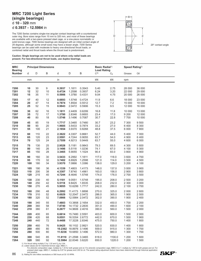
86
MRC 7200 Light Series(single bearings)d 10 - 320 mmd 0.3937 - 12.5984 in
The 7200 Series contains single-row angular contact bearings with a counterboredouter ring. Bore sizes range from 10 mm to 320 mm, and most of these bearingsare available with a two-piece pressed steel cage, or a one-piece nonmetallic orsolid bronze cage. 7000 Series bearings are designed with an initial contact angle of29 degrees, although some small sizes may have a lesser angle. 7200 Seriesbearings can be used with moderate to heavy one-directional thrust loads, orcombined radial and thrust loads where the thrust load is predominant.
Caution: Single bearings are not to be used where only radial loads arepresent. For two-directional thrust loads, use duplex bearings.
7200 10 30 9 0.3937 1.1811 0.3543 5.40 2.75 28 000 36 0007201 12 32 10 0.4724 1.2598 0.3937 6.24 3.20 22 000 29 0007202 15 35 11 0.5906 1.3780 0.4331 9.04 4.75 20 000 26 000
7203 17 40 12 0.6693 1.5748 0.4724 11.9 6.6 18 000 23 0007204 20 47 14 0.7874 1.8504 0.5512 12.7 7.2 15 000 19 0007205 25 52 15 0.9843 2.0472 0.5906 15.3 9.5 12 000 16 000
7206 30 62 16 1.1811 2.4409 0.6299 16.8 11.8 10 000 13 0007207 35 72 17 1.3780 2.8346 0.6693 23.4 17.0 9 200 12 0007208 40 80 18 1.5748 3.1496 0.7087 30.7 22.8 7 700 10 000
7209 45 85 19 1.7717 3.3465 0.7480 30.7 23.2 7 300 9 5007210 50 90 20 1.9685 3.5433 0.7874 33.2 27.0 6 400 8 3007211 55 100 21 2.1654 3.9370 0.8268 48.8 37.5 6 000 7 800
7212 60 110 22 2.3622 4.3307 0.8661 52.7 44.0 5 400 7 0007213 65 120 23 2.5591 4.7244 0.9055 63.7 54.0 4 900 6 4007214 70 125 24 2.7559 4.9213 0.9449 63.7 55.0 4 600 6 000
7215 75 130 25 2.9528 5.1181 0.9843 79.3 69.5 4 300 5 6007216 80 140 26 3.1496 5.5118 1.0236 74.1 67.0 4 100 5 3007217 85 150 28 3.3465 5.9055 1.1024 90.4 83.0 3 800 4 900
7218 90 160 30 3.5433 6.2992 1.1811 117.0 118.0 3 600 4 7007219 95 170 32 3.7402 6.6929 1.2598 121.0 114.0 3 500 4 5007220 100 180 34 3.9370 7.0866 1.3386 138.0 129.0 3 200 4 100
7221 105 190 36 4.1339 7.4803 1.4173 148.0 137.0 3 000 3 9007222 110 200 38 4.3307 7.8740 1.4961 163.0 156.0 2 900 3 8007224 120 215 40 4.7244 8.4646 1.5748 174.0 176.0 2 700 3 500
7226 130 230 40 5.1181 9.0551 1.5748 195.0 208.0 2 500 3 2007228 140 250 42 5.5118 9.8425 1.6535 208.0 232.0 2 300 3 0007230 150 270 45 5.9055 10.6299 1.7717 242.0 280.0 2 100 2 700
7232 160 290 48 6.2992 11.4173 1.8898 270.0 325.0 2 000 2 6007234 170 310 52 6.6929 12.2047 2.0472 286.0 365.0 1 900 2 5007236 180 320 52 7.0866 12.5984 2.0472 302.0 390.0 1 900 2 400
7238 190 340 55 7.4803 13.3858 2.1654 332.0 450.0 1 700 2 2007240 200 360 58 7.8740 14.1732 2.2835 351.0 490.0 1 600 2 1007242 210 380 61 8.2677 14.9606 2.4016 390.0 560.0 1 500 2 000
7244 220 400 65 8.6614 15.7480 2.5591 403.0 600.0 1 500 2 0007246 230 420 68 9.0551 16.5354 2.6772 442.0 670.0 1 500 1 9007248 240 440 72 9.4488 17.3228 2.8346 475.0 750.0 1 400 1 800
7250 250 460 76 9.8425 18.1102 2.9921 520.0 830.0 1 400 1 8007252 260 480 80 10.2362 18.8976 3.1496 559.0 915.0 1 300 1 7007256 280 500 80 11.0236 19.6850 3.1496 572.0 980.0 1 300 1 700
7260 300 540 85 11.8110 21.2598 3.3465 618.0 1100.0 1 200 1 6007264 320 580 92 12.5984 22.8346 3.6220 650.0 1220.0 1 200 1 500
1) For thrust rating multiply C by 1.32 and C0 by 2.94.2) Listed values are for machined bronze cage, ABEC-1.
For phenolic composition cage, multiply by 1.33 for both grease and oil. For phenolic composition cage, ABEC-5 or 7, multiply by 1.86 for both grease and oil. Forpressed steel cage, ABEC-1, multiply by 0.67 for grease and 0.80 for oil. The speed rating adjustment factors have been determined through historical applicationand practice.
3) Rating for one million revolutions or 500 hours at 33 1/3 RPM.
MRC Principal Dimensions Basic Radial1) Speed Rating2)
Bearing Load RatingNumber d D B d D B C3) C0 Grease Oil
mm in kN kN rpm
D
B
d
29° contact angle

1) For thrust rating multiply C by 0.81 and C0 by 1.47.2) Listed values are for machined bronze cage, ABEC-1.
For phenolic composition cage, multiply by 1.33 for both grease and oil. For phenolic composition cage, ABEC-5 or 7, multiply by 1.86 for both grease andoil. For pressed steel cage, ABEC-1, multiply by 0.67 for grease and 0.80 for oil. The speed rating adjustment factors have been determined throughhistorical application and practice.
3) Rating for one million revolutions or 500 hours at 33 1/3 RPM.
Use these values for back-to-back (DB) or face-to-face (DF)mounting arrangements.
7200-D 10 30 18 0.3937 1.1811 0.7087 8.8 5.5 22 000 29 0007201-D 12 32 20 0.4724 1.2598 0.7874 10.1 6.4 18 000 23 0007202-D 15 35 22 0.5906 1.3780 0.8661 14.8 9.5 16 000 21 000
7203-D 17 40 24 0.6693 1.5748 0.9449 19.5 13.2 14 000 18 0007204-D 20 47 28 0.7874 1.8504 1.1024 20.8 14.6 12 000 15 0007205-D 25 52 30 0.9843 2.0472 1.1811 25.1 19.0 9 600 13 000
7206-D 30 62 32 1.1811 2.4409 1.2598 27.6 23.6 8 000 10 0007207-D 35 72 34 1.3780 2.8346 1.3386 37.7 34.0 7 400 9 6007208-D 40 80 36 1.5748 3.1496 1.4173 49.4 45.5 6 200 8 000
7209-D 45 85 38 1.7717 3.3465 1.4961 49.4 46.5 5 800 7 6007210-D 50 90 40 1.9685 3.5433 1.5748 54.0 54.0 5 100 6 6007211-D 55 100 42 2.1654 3.9370 1.6535 79.3 75.0 4 800 6 200
7212-D 60 110 44 2.3622 4.3307 1.7323 85.2 88.0 4 300 5 6007213-D 65 120 46 2.5591 4.7244 1.8110 104.0 110.0 3 900 5 1007214-D 70 125 48 2.7559 4.9213 1.8898 104.0 110.0 3 700 4 800
7215-D 75 130 50 2.9528 5.1181 1.9685 130.0 140.0 3 400 4 5007216-D 80 140 52 3.1496 5.5118 2.0472 121.0 134.0 3 300 4 2007217-D 85 150 56 3.3465 5.9055 2.2047 148.0 166.0 3 000 3 900
7218-D 90 160 60 3.5433 6.2992 2.3622 190.0 236.0 2 900 3 8007219-D 95 170 64 3.7402 6.6929 5.5197 199.0 228.0 2 800 3 6007220-D 100 180 68 3.9370 7.0866 2.6772 225.0 260.0 2 600 3 300
7221-D 105 190 72 4.1339 7.4803 2.8346 242.0 295.0 2 400 3 1007222-D 110 200 76 4.3307 7.8740 2.9921 265.0 310.0 2 300 3 0007224-D 120 215 80 4.7244 8.4646 3.1496 281.0 355.0 2 200 2 800
7226-D 130 230 80 5.1181 9.0551 3.1496 319.0 415.0 2 000 2 6007228-D 140 250 84 5.5118 9.8425 3.3071 338.0 465.0 1 800 2 4007230-D 150 270 90 5.9055 10.6299 3.5435 397.0 560.0 1 700 2 200
7232-D 160 290 96 6.2992 11.4173 3.7795 442.0 670.0 1 600 2 1007234-D 170 310 104 6.6929 12.2047 4.0945 468.0 735.0 1 500 2 0007236-D 180 320 104 7.0866 12.5984 4.0945 494.0 780.0 1 500 1 900
7238-D 190 340 110 7.4803 13.3858 4.3307 540.0 900.0 1 400 1 8007240-D 200 360 116 7.8740 14.1732 4.5669 572.0 965.0 1 300 1 7007242-D 210 380 122 8.2677 14.9606 4.8031 637.0 1120.0 1 200 1 600
7244-D 220 400 130 8.6614 15.7480 5.1181 650.0 1200.0 1 200 1 6007246-D 230 420 136 9.0551 16.5354 5.3543 715.0 1340.0 1 200 1 5007248-D 240 440 144 9.4488 17.3228 5.6693 780.0 1500.0 1 100 1 400
7250-D 250 460 152 9.8425 18.1102 5.9842 852.0 1660.0 1 100 1 4007252-D 260 480 160 10.2362 18.8976 6.2992 904.0 1830.0 1 000 1 4007256-D 280 500 160 11.0236 19.6850 6.2992 936.0 2000.0 1 000 1 400
7260-D 300 540 170 11.8110 21.2598 6.6929 1010.0 2200.0 960 1 3007264-D 320 580 184 12.5984 22.8346 7.2441 1060.0 2400.0 960 1 200
MRC Principal Dimensions Basic Radial1) Speed Rating2)
Bearing Load RatingNumber d D B d D B C3) C0 Grease Oil
mm in kN kN rpm
87
MRC 7200-D light series, duplexd 10 - 320 mm
d 0.3937 - 12.5984 in
D
B
d "D" indicates a duplex ground half pair matched with anidentical half pair and is followed by an additional suffixletter to describe the type of duplex.
Note: ABEC 1 & 3 are stocked as half pairs, where available.
29° contact angle

MRC 7300 Medium Series(Single bearings)d 10 - 280 mmd 0.3937 - 11.0236 in
7300 series bearings have the same ring and ball cageconstruction as the 7200 Series but are heavier sectionedbearings with a ball complement capable of handling heavierloads. 7300 Series are listed with bore sizes from 10 mm to 280mm. For two directional thrust loads, use duplex bearings.
Caution: Single bearings are not to be used where onlyradial loads are present. For two-direction thrust loads, useduplex bearings.
88
7300 10 36 11 0.3937 1.3780 .4331 6.37 3.20 24 000 31 0007301 12 37 12 0.4724 1.4567 0.4724 7.02 3.75 19 000 25 0007302 15 42 13 0.5906 1.6535 0.5118 13.50 7.10 16 000 21 0007303 17 47 14 0.6693 1.8504 0.5512 15.9 8.65 15 000 19 000
7304 20 52 15 0.7874 2.0472 0.5906 18.6 10.6 13 000 17 0007305 25 62 17 0.9843 2.4409 0.6693 21.2 13.7 11 000 14 0007306 30 72 19 1.1811 2.8346 0.7480 28.1 18.6 9 200 12 0007307 35 80 21 1.3780 3.1496 0.8268 35.8 24.0 8 500 11 000
7308 40 90 23 1.5748 3.5433 0.9055 44.2 30.5 7 300 9 5007309 45 100 25 1.7717 3.9370 0.9843 52.7 37.5 6 400 8 3007310 50 110 27 1.9685 4.3307 1.0630 74.1 53.0 5 800 7 5007311 55 120 29 2.1654 4.7244 1.1417 85.2 62.0 5 100 6 600
7312 60 130 31 2.3622 5.1181 1.2205 97.5 72.0 4 900 6 4007313 65 140 33 2.5591 5.5118 1.2992 108.0 86.5 4 600 6 0007314 70 150 35 2.7559 5.9055 1.3780 111.0 85.0 4 100 5 3007315 75 160 37 2.9528 6.2992 1.4567 138.0 114.0 3 900 5 000
7316 80 170 39 3.1496 6.6929 1.5354 143.0 120.0 3 600 4 7007317 85 180 41 3.3465 7.0866 1.6142 163.0 143.0 3 500 4 5007318 90 190 43 3.5433 7.4803 1.6299 168.0 150.0 3 200 4 2007319 95 200 45 3.7402 7.8740 1.7717 178.0 166.0 3 100 4 000
7320 100 215 47 3.9370 8.4646 1.8504 190.0 183.0 3 000 3 9007321 105 225 49 4.1339 8.8583 1.9291 203.0 200.0 2 900 3 8007322 110 240 50 4.3307 9.4488 1.9685 229.0 236.0 2 700 3 5007324 120 260 55 4.7244 10.2362 2.1654 260.0 275.0 2 500 3 200
7326 130 280 58 5.1181 11.0236 2.2835 286.0 320.0 2 300 3 0007328 140 300 62 5.5118 11.8110 2.4409 312.0 375.0 2 200 2 8007330 150 320 65 5.9055 12.5984 2.5591 345.0 430.0 2 000 2 6007332 160 340 68 6.2992 13.3858 2.6772 377.0 490.0 1 900 2 500
7334 170 360 72 6.6929 14.1732 2.8346 397.0 520.0 1 900 2 4007336 180 380 75 7.0866 14.9606 2.9528 423.0 585.0 1 800 2 3007338 190 400 78 7.4803 15.7480 3.0709 462.0 655.0 1 600 2 1007340 200 420 80 7.8740 16.5354 3.1496 494.0 720.0 1 500 2 000
7342 210 440 84 8.2677 17.3228 3.3071 527.0 800.0 1 500 1 9007344 220 460 88 8.6614 18.1102 3.4646 559.0 865.0 1 400 1 8007348 240 500 95 9.4488 19.6850 3.7402 605.0 965.0 1 400 1 700
7352 260 540 102 10.2362 21.2598 4.0157 663.0 1140.0 1 300 1 6007356 280 580 108 11.0236 22.8346 4.2520 741.0 1340.0 1 200 1 500
MRC Principal Dimensions Basic Radial1) Speed Rating2)
Bearing Load RatingNumber C3) C0 Grease Oil
d D B d D B
mm in kN kN rpm
1) For thrust rating multiply C by 1.32 and C0 by 2.942) Listed values are for machined bronze cage, ABEC-1.
For phenolic composition cage, multiply by 1.33 for both grease and oil. For phenolic composition cage, ABEC-5 or 7, multiply by 1.86 for bothgrease and oil. For pressed steel cage, ABEC-1, multiply by 0.67 for grease and 0.80 for oil. The speed rating adjustment factors have beendetermined through historical application and practice.
3) Rating for one million revolutions or 500 hours at 33 1/3 RPM.
D
B
d
29° contact angle

89
7300-D 10 36 22 0.3937 1.3780 0.8661 10.4 6.4 19 000 25 0007301-D 12 37 24 0.4724 1.4567 0.9449 11.4 7.5 15 000 20 0007302-D 15 42 26 0.5906 1.6535 1.0236 21.6 14.3 13 000 17 0007303-D 17 47 28 0.6693 1.8504 1.1024 26.0 17.3 12 000 15 000
7304-D 20 52 30 0.7874 2.0472 1.1811 30.2 21.2 10 000 14 0007305-D 25 62 34 0.9843 2.4409 1.3386 34.5 27.0 8 800 11 0007306-D 30 72 38 1.1811 2.8346 1.4961 46.2 37.5 7 400 9 6007307-D 35 80 42 1.3780 3.1496 1.6535 58.5 48.0 6 800 8 800
7308-D 40 90 46 1.5748 3.5433 1.8110 71.5 61.0 5 800 7 6007309-D 45 100 50 1.7717 3.9370 1.9685 85.2 75.0 5 100 6 6007310-D 50 110 54 1.9685 4.3307 2.1260 121.0 106.0 4 600 6 0007311-D 55 120 58 2.1654 4.7244 2.2835 140.0 125.0 4 100 5 300
7312-D 60 130 62 2.3622 5.1181 2.4409 159.0 146.0 3 900 5 1007313-D 65 140 66 2.5591 5.5118 2.5984 178.0 173.0 3 700 4 8007314-D 70 150 70 2.7559 5.9055 2.7559 182.0 170.0 3 300 4 2007315-D 75 160 74 2.9528 6.2992 2.9134 225.0 228.0 3 100 4 000
7316-D 80 170 78 3.1496 6.6929 3.0709 234.0 240.0 2 900 3 8007317-D 85 180 82 3.3465 7.0866 3.2283 265.0 285.0 2 800 3 6007318-D 90 190 86 3.5433 7.4803 3.3858 276.0 300.0 2 600 3 4007319-D 95 200 90 3.7402 7.8740 3.5433 291.0 325.0 2 500 3 200
7320-D 100 215 94 3.9370 8.4646 3.7008 312.0 365.0 2 400 3 1007321-D 105 225 98 4.1339 8.8583 3.8583 332.0 400.0 2 300 3 0007322-D 110 240 100 4.3307 9.4488 3.9370 371.0 475.0 2 200 2 8007324-D 120 260 110 4.7244 10.2362 4.3307 423.0 560.0 2 000 2 600
7326-D 130 280 116 5.1181 11.0236 4.5669 468.0 640.0 1 800 2 4007328-D 140 300 124 5.5118 11.8110 4.8819 507.0 735.0 1 800 2 2007330-D 150 320 130 5.9055 12.5984 5.1181 559.0 865.0 1 600 2 1007332-D 160 340 136 6.2992 13.3858 5.3543 618.0 965.0 1 500 2 000
7334-D 170 360 144 6.6929 14.1732 5.6693 650.0 1040.0 1 500 1 9007336-D 180 380 150 7.0866 14.9606 5.9055 689.0 1160.0 1 400 1 8007338-D 190 400 156 7.4803 15.748 6.1417 761.0 1290.0 1 300 1 7007340-D 200 420 160 7.8740 16.5354 6.2992 806.0 1430.0 1 200 1 600
7342-D 210 440 168 8.2677 17.3228 6.6142 852.0 1600.0 1 200 1 5007344-D 220 460 176 8.6614 18.1102 6.9291 904.0 1730.0 1 100 1 4007348-D 240 500 190 9.4488 19.6850 7.4803 975.0 1930.0 1 000 1 400
7352-D 260 540 204 10.2362 21.2598 8.0315 1080.0 2280.0 960 1 3007356-D 280 580 216 11.0236 22.8346 8.5309 1210.0 2650.0 960 1 200
MRC Principal Dimensions Basic Radial1) Speed Rating2)
Bearing Load RatingNumber C3) C0 Grease Oil
d D B d D B
mm in kN kN rpm
1) For thrust rating multiply C by 0.81 and C0 by 1.47.2) Listed values are for machined bronze cage, ABEC-1.
For phenolic composition cage, multiply by 1.33 for both grease and oil. For phenolic composition cage, ABEC-5 or 7, multiply by 1.86 for bothgrease and oil. For pressed steel cage, ABEC-1, multiply by 0.67 for grease and 0.80 for oil. The speed rating adjustment factors have beendetermined through historical application and practice.
3) Rating for one million revolutions or 500 hours at 33 1/3 RPM.
MRC 7300-D medium series, duplexd 10 - 280 mm
d 0.3937 - 11.0236 in
D
B
d"D" indicates a duplex ground half pair matched with anidentical half pair and is followed by an additional suffix letter todescribe the type of duplex.
Use these values for back-to-back (DB) or face-to-face (DF) mountingarrangements.
Note: ABEC 1 & 3 are stocked as half pairs where available.
29° contact angle

D
B
d
90
7403 17 62 17 0.6693 2.4409 0.6693 26.0 13.7 14 000 18 0007404 20 72 19 0.7874 2.8346 0.748 32.5 17.6 12 000 15 0007405 25 80 21 0.9843 3.1496 0.8268 42.3 24.5 9 200 12 0007406 30 90 23 1.1811 3.5433 0.9055 54.0 34.0 7 700 10 000
7407 35 100 25 1.3780 3.937 0.9843 63.7 40.5 6 600 8 5007408 40 110 27 1.5748 4.3307 1.063 74.1 49.0 5 400 7 7007409 45 120 29 1.7717 4.7244 1.1417 85.2 57.0 5 300 6 9007410 50 130 31 1.9685 5.1181 1.2205 95.6 72.0 4 900 6 400
7411 55 140 33 2.1654 5.5118 1.2992 108.0 78.0 4 500 5 8007412 60 150 35 2.3622 5.9055 1.378 127.0 93.0 4 100 5 3007413 65 160 37 2.5591 6.2992 1.4567 138.0 106.0 3 800 4 9007414 70 180 42 2.7559 7.0866 1.6535 168.0 140.0 3 500 4 600
7415 75 190 45 2.9528 7.4803 1.7717 182.0 156.0 3 300 4 3007416 80 200 48 3.1496 7.874 1.8898 190.0 170.0 3 200 4 1007417 85 210 52 3.3465 8.2677 2.0472 203.0 186.0 2 900 3 8007418 90 225 54 3.5433 8.8583 2.126 229.0 220.0 2 700 3 500
7419 95 250 55 3.7402 9.8425 2.1654 255.0 255.0 2 500 3 3007420 100 265 60 9.9370 10.4331 2.3622 276.0 290.0 2 400 3 2007421 105 290 65 4.1339 11.4173 2.5591 332.0 325.0 2 300 3 0007422 110 320 70 4.3307 12.5984 2.7559 371.0 390.0 2 200 2 900
7403-D 17 62 34 0.6693 2.4409 1.3386 42.3 27.0 11 000 14 0007404-D 20 72 38 0.7874 2.8346 1.4961 52.7 35.5 9 600 12 0007405-D 25 80 42 0.9843 3.1496 1.6535 68.9 49.0 7 400 9 6007406-D 30 90 46 1.1811 3.5433 1.811 88.4 68.0 6 200 8 000
7407-D 35 100 50 1.3780 3.937 1.9685 104.0 81.5 5 300 6 8007408-D 40 110 54 1.5748 4.3307 2.126 121.0 96.5 4 300 6 2007409-D 45 120 58 1.7717 4.7244 2.2835 138.0 114.0 4 200 5 5007410-D 50 130 62 1.9685 5.1181 2.4409 156.0 146.0 3 900 5 100
7411-D 55 140 66 2.1654 5.5118 2.5984 178.0 156.0 3 600 4 6007412-D 60 150 70 2.3622 5.9055 2.7559 203.0 190.0 3 300 4 2007413-D 65 160 74 2.5591 6.2992 2.9134 225.0 275.0 3 000 3 9007414-D 70 180 84 2.7559 7.0866 3.3071 276.0 280.0 2 800 3 700
7415-D 75 190 90 2.9528 7.4803 3.5433 291.0 310.0 2 600 3 4007416-D 80 200 96 3.1496 7.874 3.7795 312.0 340.0 2 500 3 3007417-D 85 210 104 3.3465 8.2677 4.0945 332.0 375.0 2 300 3 0007418-D 90 225 108 3.5433 8.8583 4.252 371.0 440.0 2 200 2 800
7419-D 95 250 110 3.7402 9.8425 4.3307 410.0 510.0 2 000 2 6007420-D 100 265 120 9.9370 10.4331 4.7244 449.0 585.0 1 900 2 6007421-D 105 290 130 4.1339 11.4173 5.1181 540.0 670.0 1 800 2 4007422-D 110 320 140 4.3307 12.5984 5.5118 605.0 800.0 1 700 2 300
MRC Principal Dimensions Basic Radial1) Speed Rating2)
Bearing Load RatingNumber C3) C0 Grease Oil
d D B d D B
mm in kN kN rpm
MRC 7400 heavy series andMRC 7400-D heavy seriesd 17 - 110 mmd 0.6693 - 4.3307 in
7400 Series bearings are similar to the 7200 and 7300 Series but areheavier sectioned and are used for heavy one-directional thrust loads orcombined radial and thrust loads where the thrust load is predominant.
"D" indicates a duplex ground half pair matched with an identical half pair and iffollowed by an additional suffix letter to describe the type of duplex.
Caution: Single bearings are not to be used where only radial loads arepresent. For two-direction thrust loads, use duplex bearings.
1) For thrust rating multiply C by 1.32 and C0 by 2.94 (single) and C by 0.81 and C0 by 1.47 (duplex)2) Listed values are for machined bronze cage, ABEC-1.
For phenolic composition cage, multiply by 1.33 for both grease and oil. For phenolic composition cage, ABEC-5 or 7, multiply by 1.86 for bothgrease and oil. For pressed steel cage, ABEC-1, multiply by 0.67 for grease and 0.80 for oil. The speed rating adjustment factors have beendetermined through historical application and practice.
3) Rating for one million revolutions or 500 hours at 33 1/3 RPM.
Values for -D bearings are for back-to-back (DB) or face-to-face (DF) mounting arrangements.
Note: ABEC 1 & 3 are stocked as half pairs where available.
29° contact angle

91
Double row angular contact ball bearingsd 10 - 65 mm
d 0.397 - 2.582 in
10 30 14 0.3937 1.1811 0.5512 7.61 4.3 0.183 22 000 24 000 0.051 – 3200 ATN9
12 32 15.9 0.4724 1.2598 0.6260 10.1 5.6 0.24 20 000 22 000 0.058 – 3201 ATN9
15 35 15.9 0.5906 1.3780 0.6260 11.2 6.8 0.285 17 000 18 000 0.066 – 3202 ATN942 19 1.6535 0.7480 15.1 9.3 0.4 15 000 16 000 0.13 – 3302 ATN9
17 40 17.5 0.6693 1.5748 0.6890 14.3 8.8 0.365 15 000 16 000 0.096 – 3203 ATN947 22.2 1.8504 0.8740 21.6 12.7 0.54 14 000 14 000 0.18 – 3303 ATN9
20 47 20.6 0.7874 1.8504 0.8110 20 12 0.51 14 000 14 000 0.16 * 3204 A * 3204 ATN952 22.2 2.0472 0.8740 23.6 14.6 0.62 13 000 13 000 0.22 * 3304 A * 3304 ATN9
25 52 20.6 0.9843 2.0472 0.8110 21.6 14.3 0.6 12 000 12 000 0.18 * 3205 A * 3205 ATN962 25.4 2.4409 1.0000 32 20.4 0.865 11 000 11 000 0.35 * 3305 A * 3305 ATN9
30 62 23.8 1.1811 2.4409 0.9370 30 20.4 0.865 10 000 10 000 0.29 * 3206 A * 3206 ATN972 30.2 2.8346 1.1890 41.5 27.5 1.16 9 000 9 000 0.53 * 3306 A * 3306 ATN9
35 72 27 1.3780 2.8346 1.0630 40 28 1.18 9 000 9 000 0.44 * 3207 A * 3207 ATN980 34.9 3.1496 1.3740 52 35.5 1.5 8 500 8 500 0.71 * 3307 A * 3307 ATN980 34.9 3.1496 1.3740 52.7 41.5 1.76 7 500 8 000 0.79 3307 DJ1 –
40 80 30.2 1.5748 3.1496 1.1890 47.5 34 1.43 8 000 8 000 0.58 * 3208 A * 3208 ATN990 36.5 3.5433 1.4370 64 44 1.86 7 500 7 500 1.05 * 3308 A * 3308 ATN990 36.5 3.5433 1.4370 49.4 41.5 1.76 6 700 7 000 1.2 3308 DNRCBM –90 36.5 3.5433 1.4370 68.9 64 2.45 6 700 7 000 1.05 3308 DMA 3308 DTN9
45 85 30.2 1.7717 3.3465 1.1890 51 39 1.63 7 500 7 500 0.63 * 3209 A * 3209 ATN9100 39.7 3.9370 1.5630 75 53 2.24 6 700 6 700 1.4 * 3309 A * 3309 ATN9100 39.7 3.9370 1.5630 61.8 52 2.2 6 000 6 300 1.5 3309 DNRCBM –100 39.7 3.9370 1.5630 79.3 69.5 3 6 000 6 300 1.6 3309 DMA –
50 90 30.2 1.9685 3.5433 1.1890 51 39 1.66 7 000 7 000 0.66 * 3210 A * 3210 ATN9110 44.4 4.3307 1.7480 90 64 2.75 6 000 6 000 1.95 * 3310 A * 3310 ATN9110 44.4 4.3307 1.7480 81.9 69.5 3 5 300 5 600 1.95 3310 DNRCBM –110 44.4 4.3307 1.7480 93.6 85 3.6 5 300 5 600 2.15 3310 DMA –
55 100 33.3 2.1654 3.9370 1.3110 60 47.5 2 6 300 6 300 1.05 * 3211 A * 3211 ATN9120 49.2 4.7244 1.9370 112 81.5 3.45 5 300 5 300 2.55 * 3311 A –120 49.2 4.7244 1.9370 95.6 83 3.55 4 800 5 000 2.55 3311 DNRCBM –120 49.2 4.7244 1.9370 111 100 4.3 4 800 5 000 2.8 3311 DMA –
60 110 36.5 2.3622 4.3307 1.4370 73.5 58.5 2.5 5 600 5 600 1.4 * 3212 A * 3212 ATN9130 54 5.1181 2.1260 127 95 4.05 5 000 5 000 3.25 * 3312 A –
65 120 38.1 2.5591 4.7244 1.5000 80.6 73.5 3.1 4 500 4 800 1.75 3213 A –140 58.7 5.5118 2.3110 146 110 4.55 4 500 4 500 4.1 * 3313 A –140 58.7 5.5118 2.3110 138 122 5.1 4 300 4 500 4 3313 DNRCBM –
Principal dimensions Basic load ratings Fatigue Speed ratings Mass Designationsdynamic static load Reference Limiting Bearing with
limit speed speed metal cage polyamided D B d D B C C0 Pu cage
mm in kN kN r/min kg –
B
D d
* SKF Explorer bearing
30° contact angle

92
70 125 39.7 2.7559 4.9213 1.5630 88.4 80 3.4 4 300 4 500 1.9 3214 A –150 63.5 5.9055 2.5000 153 125 5 4 000 4 000 5.05 3314 A –
75 130 41.3 2.9528 5.1181 1.6260 95.6 88 3.75 4 300 4 500 2.1 3215 A –160 68.3 6.2992 2.6890 176 140 5.5 4 000 4 000 5.55 * 3315 A –
80 140 44.4 3.1496 5.5118 1.7480 106 95 3.9 4 000 4 300 2.65 3216 A –170 68.3 6.6929 2.6890 182 156 6 3 400 3 600 6.8 3316 A –170 68.3 6.6929 2.6890 190 196 7.35 3 400 3 600 7.55 3316 DMA –
85 150 49.2 3.3465 5.9055 1.9370 124 110 4.4 3 600 3 800 3.4 3217 A –180 73 7.0866 2.8740 195 176 6.55 3 200 3 400 8.3 3317 A –
90 160 52.4 3.5433 6.2992 2.0630 130 120 4.55 3 400 3 600 4.15 3218 A –190 73 7.4803 2.8740 195 180 6.4 3 000 3 200 9.25 3318 A –190 73 7.4803 2.8740 225 250 8.8 3 000 3 200 10 3318 DMA –
95 170 55.6 3.7402 6.6929 2.1890 159 146 5.4 3 200 3 400 5 3219 A –200 77.8 7.8740 3.0630 225 216 7.5 2 800 3 000 11 3319 A –200 77.8 7.8740 3.0630 242 275 9.5 2 800 3 000 12 3319 DMA –
100 180 60.3 3.9370 7.0866 2.3740 178 166 6 3 000 3 200 6.1 3220 A –215 82.6 8.4646 3.2520 255 255 8.65 2 600 2 800 13.5 3320 A –
110 200 69.8 4.3307 7.8740 2.7480 212 212 7.2 2 800 2 800 8.8 3222 A –240 92.1 9.4488 3.6260 291 305 9.8 2 400 2 600 19 3322 A –
Principal dimensions Basic load ratings Fatigue Speed ratings Mass Designationsdynamic static load Reference Limiting Bearing with
limit speed speed metal cage polyamided D B d D B C C0 Pu cage
mm in kN kN r/min kg –
Double row angular contact ball bearingsd 70 - 110 mmd 2.781 - 4.370 in
d 40 - 80 mmd 1.575 - 3.150 in
* SKF Explorer bearing
B
D d
30° contact angle
5408 A 40 1.5748 110 4.3307 49.2 1-15/16 88 400 19 900 57 000 12 800 – 4 300 5 600 2.30 5.055409 A 45 1.7717 120 4.7244 54.0 2-1/8 112 000 25 200 78 000 17 600 – 4 000 5 300 3.00 6.605410 A 50 1.9685 130 5.1181 58.7 2-5/16 143 000 32 200 102 000 23 000 – 3 600 4 800 3.70 8.15
5411 A 55 2.1654 140 5.5118 63.5 2-1/2 146 000 32 900 102 000 23 000 – 3 200 4 300 4.70 10.505412 A 60 2.3622 150 5.9055 66.7 2-5/8 159 000 35 800 114 000 25 700 – 3 000 4 000 5.70 12.505413 A 65 2.5591 160 6.2992 71.4 2-13/16 195 000 43 900 156 000 35 100 – 2 800 3 800 6.75 15.00
5414 A 70 2.7559 180 7.0866 79.4 3-1/8 199 000 44 800 156 000 35 100 – 2 400 3 400 9.90 22.005415 A 75 2.9528 190 7.4803 82.55 3-1/4 225 000 50 600 190 000 42 800 – 2 200 3 200 11.16 24.605416 A 80 3.1496 200 7.8740 87.31 3-7/16 238 000 53 600 208 000 46 800 – 2 000 3 000 13.00 28.80
Designation Principal Dimensions Basic Load Ratings Speed Rating Massdynamic static Lubrication
d D B C C0 Seal Grease Oil
mm in mm in mm in N lbf N lbf rpm rpm rpm kg lb

93
10 30 14 0.394 1.181 0.551 7.61 4.3 0.183 24 000 17 000 0.051 3200 A-2Z 3200 A-2RS1
12 32 15.9 0.472 1.260 0.626 10.1 5.6 0.24 22 000 15 000 0.058 3201 A-2Z 3201 A-2RS1
15 35 15.9 0.591 1.378 0.626 11.2 6.8 0.285 18 000 14 000 0.066 3202 A-2Z 3202 A-2RS142 19 1.654 0.748 15.1 9.3 0.4 16 000 12 000 0.13 3302 A-2Z 3302 A-2RS1
17 40 17.5 0.669 1.575 0.689 14.3 8.8 0.365 16 000 12 000 0.1 3203 A-2Z 3203 A-2RS147 22.2 1.850 0.874 21.6 12.7 0.54 14 000 11 000 0.18 3303 A-2Z 3303 A-2RS1
20 47 20.6 0.787 1.850 0.811 20 12 0.51 14 000 10 000 0.16 * 3204 A-2Z * 3204 A-2RS152 22.2 2.047 0.874 23.6 14.6 0.62 13 000 9 000 0.22 * 3304 A-2Z * 3304 A-2RS1
25 52 20.6 0.984 2.047 0.811 21.6 14.3 0.6 12 000 8 500 0.18 * 3205 A-2Z * 3205 A-2RS162 25.4 2.441 1.000 32 20.4 0.865 11 000 7 500 0.35 * 3305 A-2Z * 3305 A-2RS1
30 62 23.8 1.181 2.441 0.937 30 20.4 0.865 10 000 7 500 0.29 * 3206 A-2Z * 3206 A-2RS172 30.2 2.835 1.189 41.5 27.5 1.16 9 000 6 300 0.52 * 3306 A-2Z * 3306 A-2RS1
35 72 27 1.378 2.835 1.063 40 28 1.18 9 000 6 300 0.44 * 3207 A-2Z * 3207 A-2RS180 34.9 3.150 1.374 52 35.5 1.5 8 500 6 000 0.73 * 3307 A-2Z * 3307 A-2RS1
40 80 30.2 1.575 3.150 1.189 47.5 34 1.43 8 000 5 600 0.57 * 3208 A-2Z * 3208 A-2RS190 36.5 3.543 1.437 64 44 1.86 7 500 5 000 0.93 * 3308 A-2Z * 3308 A-2RS1
45 85 30.2 1.772 3.346 1.189 51 39 1.63 7 500 5 300 0.63 * 3209 A-2Z * 3209 A-2RS1100 39.7 3.937 1.563 75 53 2.24 6 700 4 800 1.25 * 3309 A-2Z * 3309 A-2RS1
50 90 30.2 1.969 3.543 1.189 51 39 1.66 7 000 4 800 0.65 * 3210 A-2Z * 3210 A-2RS1110 44.4 4.331 1.748 90 64 2.75 6 000 4 300 1.7 * 3310 A-2Z * 3310 A-2RS1
55 100 33.3 2.165 3.937 1.311 60 47.5 2 6 300 4 500 0.91 * 3211 A-2Z * 3211 A-2RS1120 49.2 4.724 1.937 112 81.5 3.45 5 300 3 800 2.65 * 3311 A-2Z * 3311 A-2RS1
60 110 36.5 2.362 4.331 1.437 73.5 58.5 2.5 5 600 4 000 1.2 * 3212 A-2Z * 3212 A-2RS1130 54 5.118 2.126 127 95 4.05 5 000 – 2.8 * 3312 A-2Z –
65 120 38.1 2.559 4.724 1.500 80.6 73.5 3.1 4 800 3 600 1.75 3213 A-2Z 3213 A-2RS1140 58.7 5.512 2.311 146 110 4.55 4 500 – 4.1 * 3313 A-2Z –
70 125 39.7 2.756 4.921 1.563 88.4 80 3.4 4 500 – 1.9 3214 A-2Z –150 63.5 5.906 2.500 153 125 5 4 000 – 5.05 3314 A-2Z –
75 130 41.3 2.953 5.118 1.626 95.6 88 3.75 4 500 – 2.1 3215 A-2Z –160 68.3 6.299 2.689 176 140 5.5 4 000 – 5.6 * 3315 A-2Z –
Sealed double row angular contact ball bearingsd 10 - 75 mm
d 0.394 - 2.953 in
Principal dimensions Basic load ratings Fatigue Limiting speeds Mass Designationsdynamic static load Bearing with Bearing with
limit shields seals shields sealsd D B d D B C C0 Pu
mm in kN kN r/min kg –
D d
B
* SKF Explorer bearing
30° contact angle

94
Double row angular contact ball bearings
Double Row, 30° Contact AngleMax TypeOpen, Sealed, Shielded, Snap RingSeries: 5205 E — 5218 ESize: 25 mm — 90 mm0.9843 in — 3.5433 in
Series: 5305 E — 5316 ESize: 25 mm — 80 mm0.9843 in — 3.1496 in
5205 E 25 0.9843 52 2.0472 20.6 13/16 22 900 5 150 21 200 4 770 8 000 8 000 11 000 0.25 0.555206 E 30 1.1811 62 2.4409 23.8 15/16 30 300 6 820 28 000 6 290 7 000 7 000 9 500 0.35 0.775207 E 35 1.3780 72 2.8346 27.0 1-1/16 39 100 8 800 36 500 8 210 6 000 6 000 8 000 0.54 1.20
5208 E 40 1.5748 80 3.1496 30.2 1-3/16 49 500 11 100 49 000 11 000 5 600 5 600 7 500 0.73 1.605209 E 45 1.7717 85 3.3465 30.2 1-3/16 51 200 11 500 54 000 12 100 5 000 5 000 6 700 0.77 1.705210 E 50 1.9685 90 3.5433 30.2 1-3/16 53 900 12 100 58 500 13 200 4 800 4 800 6 300 0.82 1.80
5211 E 55 2.1654 100 3.9370 33.3 1-5/16 66 000 14 900 76 500 17 200 4 300 4 300 5 600 1.15 2.555212 E 60 2.3622 110 4.3307 36.5 1-7/16 78 100 17 600 88 000 19 800 3 800 3 800 5 000 1.50 3.305213 E 65 2.5591 120 4.7244 38.1 1-1/2 88 000 19 800 106 000 23 800 3 600 3 600 4 800 1.95 4.30
5214 E 70 2.7559 125 4.9213 39.7 1-9/16 101 000 22 700 125 000 28 100 3 200 3 200 4 300 2.15 4.755215 E 75 2.9528 130 5.1181 41.3 1-5/8 108 000 24 300 137 000 30 800 3 200 3 200 4 300 2.50 5.505216 E 80 3.1496 140 5.5118 44.4 1-3/4 128 000 28 800 160 000 36 000 – 2 800 3 800 3.00 6.60
5217 E 85 3.3465 150 5.9055 49.2 1-15/16 142 000 32 000 176 000 39 600 – 2 600 3 600 3.70 8.155218 E 90 3.5433 160 6.2992 52.4 2-1/16 151 000 34 000 193 000 43 400 – 2 400 3 400 4.55 10.00
5305 E 25 0.9843 62 2.4409 25.4 1 34 100 7 670 30 500 6 860 7 500 7 500 10 000 0.39 0.865306 E 30 1.1811 72 2.8346 30.2 1-3/16 46 800 10 500 43 000 9 670 6 300 6 300 8 500 0.59 1.305307 E 35 1.3780 80 3.1496 34.9 1-3/8 52 300 11 800 48 000 10 800 5 600 5 600 7 500 0.86 1.90
5308 E 40 1.5748 90 3.5433 36.5 1-7/16 67 100 15 100 65 500 14 700 5 000 5 000 6 700 1.15 2.555309 E 45 1.7717 100 3.9370 39.7 1-9/16 80 900 18 200 80 000 18 000 4 500 4 500 7 000 1.50 3.305310 E 50 1.9685 110 4.3307 44.4 1-3/4 95 200 21 400 95 000 21 400 4 000 4 000 5 300 2.00 4.40
5311 E 55 2.1654 120 4.7244 49.2 1-15/16 119 000 26 800 122 000 27 400 3 800 3 800 5 000 2.65 5.855312 E 60 2.3622 130 5.1181 54.0 2-1/8 134 000 30 200 143 000 32 100 3 400 3 400 4 500 3.30 7.305313 E 65 2.5591 140 5.5118 58.7 2-5/16 154 000 34 700 163 000 36 600 3 200 3 200 4 300 4.20 9.25
5314 E 70 2.7559 150 5.9055 63.5 2-1/2 172 000 38 700 186 000 41 800 2 800 2 800 3 800 5.00 11.005315 E 75 2.9528 160 6.2992 68.3 2-11/16 187 000 42 100 208 000 46 800 – 2 600 3 600 6.35 14.005316 E 80 3.1496 170 6.6929 68.3 2-11/16 201 000 45 200 236 000 53 100 – 2 400 3 400 7.25 16.00
Designation Principal Dimensions Basic Load Ratings Speed Rating MassDynamic Static Lubrication
d D B C C0 Seal Grease Oil
mm in mm in mm in N lbf N lbf r/min r/min r/min kg lb
E-Open
E-RS1 E-Z E-N
E-2RS1 E-2Z E-NR

95
15 35 11 0.591 1.378 0.433 12.7 8.3 0.36 22 000 36 000 0.062 QJ 202 N2MA –
17 40 12 0.669 1.575 0.472 15.9 10.6 0.45 19 000 30 000 0.082 QJ 203 N2MA QJ 203 MA47 14 1.850 0.551 23.4 15 0.64 17 000 28 000 0.14 QJ 303 N2MA –
20 52 15 0.787 2.047 0.591 29.6 20 0.85 15 000 24 000 0.18 QJ 304 N2MA QJ 304 MA
25 52 15 0.984 2.047 0.591 25.1 20 0.83 14 000 22 000 0.16 QJ 205 N2MA QJ 205 MA62 17 2.441 0.669 39 28 1.18 12 000 20 000 0.29 QJ 305 N2MA QJ 305 MA
30 62 16 1.181 2.441 0.630 35.1 28.5 1.2 12 000 19 000 0.24 QJ 206 N2MA QJ 206 MA72 19 2.835 0.748 49.4 38 1.63 10 000 17 000 0.42 QJ 306 N2MA QJ 306 MA
35 72 17 1.378 2.835 0.669 46.2 39 1.63 10 000 17 000 0.36 QJ 207 N2MA QJ 207 MA80 21 3.150 0.827 59.2 46.5 1.96 9 500 15 000 0.57 QJ 307 N2MA QJ 307 MA
40 80 18 1.575 3.150 0.709 52.7 45 1.9 9 000 15 000 0.45 QJ 208 N2MA QJ 208 MA90 23 3.543 0.906 71.5 58.5 2.45 8 500 14 000 0.78 QJ 308 N2MA QJ 308 MA
45 85 19 1.772 3.346 0.748 58.5 51 2.16 8 500 14 000 0.52 – QJ 209 MA100 25 3.937 0.984 93.6 76.5 3.25 7 500 12 000 1.05 QJ 309 N2MA QJ 309 MA
50 90 20 1.969 3.543 0.787 61.8 56 2.4 7 500 13 000 0.59 QJ 210 N2MA QJ 210 MA110 27 4.331 1.063 111 91.5 3.9 6 700 11 000 1.35 – QJ 310 MA
55 100 21 2.165 3.937 0.827 79.3 76.5 3.2 7 000 11 000 0.77 QJ 211 N2MA QJ 211 MA120 29 4.724 1.142 127 108 4.55 6 000 10 000 1.75 QJ 311 N2MA QJ 311 MA
60 110 22 2.362 4.331 0.866 92.3 86.5 3.65 6 300 10 000 0.99 QJ 212 N2MA QJ 212 MA130 31 5.118 1.220 146 125 5.3 5 600 9 000 2.15 QJ 312 N2MA QJ 312 MA
65 120 23 2.559 4.724 0.906 104 104 4.4 5 600 9 500 1.2 QJ 213 N2MA QJ 213 MA140 33 5.512 1.299 165 146 6.1 5 300 8 500 2.7 – QJ 313 MA
70 125 24 2.756 4.921 0.945 114 114 4.8 5 600 9 000 1.32 QJ 214 N2MA QJ 214 MA150 35 5.906 1.378 186 166 6.7 4 800 8 000 3.15 QJ 314 N2MA QJ 314 MA
75 130 25 2.953 5.118 0.984 117 122 5.2 5 300 8 500 1.45 QJ 215 N2MA QJ 215 MA160 37 6.299 1.457 199 186 7.35 4 500 7 500 3.9 QJ 315 N2MA –
80 140 26 3.150 5.512 1.024 138 146 5.85 4 800 8 000 1.85 QJ 216 N2MA QJ 216 MA170 39 6.693 1.535 216 208 8 4 300 7 000 4.6 QJ 316 N2MA –
85 150 28 3.346 5.906 1.102 148 160 6.2 4 500 7 500 2.25 QJ 217 N2MA QJ 217 MA180 41 7.087 1.614 234 236 8.65 4 000 6 700 5.45 QJ 317 N2MA –
90 160 30 3.543 6.299 1.181 174 186 6.95 4 300 7 000 2.75 QJ 218 N2MA –190 43 7.480 1.693 265 285 10.2 3 800 6 300 6.45 QJ 318 N2MA –
Four-point contact ball bearingsd 15 - 90 mm
d 0.591 - 3.543 in
Principal dimensions Basic load ratings Fatigue Speed ratings Mass Designationsdynamic static load Reference Limiting Bearing
limit speed speed with locating without loc.d D B d D B C C0 Pu slots slots
mm in kN kN r/min kg –
D
B
d
35° contact angle

96
95 170 32 3.740 6.693 1.260 199 212 7.8 4 000 6 700 3.35 QJ 219 N2MA –200 45 7.874 1.772 286 315 11 3 600 6 000 7.45 QJ 319 N2MA –
100 180 34 3.937 7.087 1.339 225 240 8.65 3 800 6 300 4.05 QJ 220 N2MA –215 47 8.465 1.850 307 340 11.6 3 400 5 600 9.3 QJ 320 N2MA –
110 200 38 4.331 7.874 1.496 265 305 10.4 3 400 5 600 5.6 QJ 222 N2MA –240 50 9.449 1.969 390 475 15 3 000 4 800 12.5 QJ 322 N2MA –
120 215 40 4.724 8.465 1.575 286 340 11.2 3 200 5 000 6.95 QJ 224 N2MA –260 55 10.236 2.165 390 490 15 2 800 4 500 16 QJ 324 N2MA –
130 230 40 5.118 9.055 1.575 296 365 11.6 2 800 4 800 7.75 QJ 226 N2MA –280 58 11.024 2.283 423 560 16.6 2 600 4 000 19.5 QJ 326 N2MA –
140 250 42 5.512 9.843 1.654 325 440 13.2 2 600 4 300 9.85 QJ 228 N2MA –300 62 11.811 2.441 468 640 18.6 2 400 3 800 24 QJ 328 N2MA –
150 270 45 5.906 10.630 1.772 377 530 15.3 2 400 4 000 12.5 QJ 230 N2MA –320 65 12.598 2.559 494 710 19.6 2 200 3 600 29 QJ 330 N2MA –
160 290 48 6.299 11.417 1.890 423 620 17.6 2 200 3 800 15.5 QJ 232 N2MA –340 68 13.386 2.677 540 815 21.6 2 000 3 400 34.5 QJ 332 N2MA –
170 310 52 6.693 12.205 2.047 436 670 18.3 2 200 3 400 19.5 QJ 234 N2MA –360 72 14.173 2.835 618 965 25 1 900 3 200 41.5 QJ 334 N2MA –
180 320 52 7.087 12.598 2.047 449 710 19 2 000 3 400 20.5 QJ 236 N2MA –380 75 14.961 2.953 637 1 020 26 1 800 3 000 47.5 QJ 336 N2MA –
190 400 78 7.480 15.748 3.071 702 1 160 28.5 1 700 2 800 49 QJ 338 N2MA –
200 360 58 7.874 14.173 2.283 540 915 23.2 1 800 3 000 28.5 QJ 240 N2MA –
Principal dimensions Basic load ratings Fatigue Speed ratings Mass Designationsdynamic static load Reference Limiting Bearing
limit speed speed with locating without loc.d D B d D B C C0 Pu slots slots
mm in kN kN r/min kg –
Four-point contact ball bearingsd 95 - 200 mmd 3.740 - 7.874 in
D
B
d
35° contact angle

97
32 14 10 1.260 0.551 0.394 17.7 25 0.6 15 7.15 3.8 0.16 16 000 0.062 305800 C-2Z –
35 15.9 12 1.378 0.626 0.472 19.1 27.7 0.6 16.5 9.56 4.9 0.208 14 000 0.078 305801 C-2Z 305701 C-2Z
40 15.9 15 1.575 0.626 0.591 22.1 30.7 0.6 18 10.6 5.85 0.25 12 000 0.1 305802 C-2Z 305702 C-2Z
47 17.5 17 1.850 0.689 0.669 25.2 35 0.6 20 13.5 7.8 0.325 11 000 0.16 305803 C-2Z 305703 C-2Z
52 20.6 20 2.047 0.811 0.787 29.4 40.9 1 24 17.2 10 0.425 9 500 0.22 305804 C-2Z 305704 C-2Z
62 20.6 25 2.441 0.811 0.984 34.4 45.9 1 26.5 19.5 12.5 0.53 8 000 0.32 305805 C-2Z 305705 C-2Z
72 23.8 30 2.835 0.937 1.181 41.4 55.2 1 31 27.6 18.6 0.8 6 700 0.49 305806 C-2Z 305706 C-2Z
80 27 35 3.150 1.063 1.378 48.1 63.9 1.1 36.5 33.2 21.2 0.9 5 600 0.65 305807 C-2Z 305707 C-2Z
Double row cam rollersd 32 - 80 mm
d 1.260 - 3.150 in
Dimensions Limiting Mass Designationsspeed Cam roller with
crowned cylindricalD B d D B d d1 D1 r1,2 a C C0 Pu runner surface runner surface
~ ~ Min
mm in kN kN r/min kg –
DD d da
B
rr
rr
12
12
11

98

99
1210 E K M C3
12
34
Self-Aligning Ball Bearings
1. Internal Design
No suffix Standard internal design
E Reinforced ball set (increased capacity)
2. Variations
K Bearing with 1:12 tapered bore
2RS1 2 rubber seals with metal backing
3. Cage Designations
TN9 Fibreglass reinforced Polyamide,ball centred
M Machined brass cage, ball centred
No symbol Steel, ball centred
4. Clearance
C2 Radial internal clearance < normal
CN Normal clearance not shown
C3 Radial internal clearance > normal
C4 Radial internal clearance > C3
Lubrication
MT33 Lithium, Medium temp. 74 cSt @ 40°C,-30°C to + 120°C
MT47 Lithium, Medium temp. 70 cSt @ 40°C,-30°C to + 110°C

100
Boundary Dimensions In accordance with ISO 15-1981
Tolerances ABEC 1 (Normal)
Heat Stabilization 257°F (125°C)
Misalignment Series 1200 2.5 degreesSeries 1300 3.0 degreesSeries 2200 2.5 degreesSeries 2200-2RS1 1.5 degreesSeries 2300 3.0 degreesSeries 2300-2RS1 1.5 degrees
Cage MaterialStandard Polyamide (TN9)Optional Machined brass (M) large bearings
Steel no symbol
Axial Load – max Fap = 3 x B x d whereon sleeves B = bearing width in mm
d = bearing bore in mmFap = axial load in Newtons
Seals 2RS1 synthetic rubber seals
Technical Features
Self-Aligning Ball Bearing (open design)(data tables on page 102)
Self-Aligning Ball Bearing (sealed design)
(data tables on page 105)
Self-aligning ball bearings

101
Bore Radial internal clearancediameterd C2 Normal C3 C4over incl. min max min max min max min max min max min max min max min maxmm µm in µm in µm in µm in
Bearings with cylindrical bore
2.5 6 1 8 0.0000 0.0003 5 15 0.0002 0.0006 10 20 0.0004 0.0008 15 25 0.0006 0.00106 10 2 9 0.0001 0.0004 6 17 0.0002 0.0007 12 25 0.0005 0.0010 19 33 0.0007 0.001310 14 2 10 0.0001 0.0004 6 19 0.0002 0.0007 13 26 0.0005 0.0010 21 35 0.0008 0.0014
14 18 3 12 0.0001 0.0005 8 21 0.0003 0.0008 15 28 0.0006 0.0011 23 37 0.0009 0.001518 24 4 14 0.0002 0.0006 10 23 0.0004 0.0009 17 30 0.0007 0.0012 25 39 0.0010 0.001524 30 5 16 0.0002 0.0006 11 24 0.0004 0.0009 19 35 0.0007 0.0014 29 46 0.0011 0.0018
30 40 6 18 0.0002 0.0007 13 29 0.0005 0.0011 23 40 0.0009 0.0016 34 53 0.0013 0.002140 50 6 19 0.0002 0.0007 14 31 0.0006 0.0012 25 44 0.0010 0.0017 37 57 0.0015 0.002250 65 7 21 0.0003 0.0008 16 36 0.0006 0.0014 30 50 0.0012 0.0020 45 69 0.0018 0.0027
65 80 8 24 0.0003 0.0009 18 40 0.0007 0.0016 35 60 0.0014 0.0024 54 83 0.0021 0.003380 100 9 27 0.0004 0.0011 22 48 0.0009 0.0019 42 70 0.0017 0.0028 64 96 0.0025 0.0038100 120 10 31 0.0004 0.0012 25 56 0.0010 0.0022 50 83 0.0020 0.0033 75 114 0.0030 0.0045
120 140 10 38 0.0004 0.0015 30 68 0.0012 0.0027 60 100 0.0024 0.0039 90 135 0.0035 0.0053
Bearings with tapered bore
18 24 7 17 0.0003 0.0007 13 26 0.0005 0.0010 20 33 0.0008 0.0013 28 42 0.0011 0.001724 30 9 20 0.0004 0.0008 15 28 0.0006 0.0011 23 39 0.0009 0.0015 33 50 0.0013 0.002030 40 12 24 0.0005 0.0009 19 35 0.0007 0.0014 29 46 0.0011 0.0018 40 59 0.0016 0.0023
40 50 14 27 0.0006 0.0011 22 39 0.0009 0.0015 33 52 0.0013 0.0020 45 65 0.0018 0.002650 65 18 32 0.0007 0.0013 27 47 0.0011 0.0019 41 61 0.0016 0.0024 56 80 0.0022 0.003165 80 23 39 0.0009 0.0015 35 57 0.0014 0.0022 50 75 0.0020 0.0030 69 98 0.0027 0.0039
80 100 29 47 0.0011 0.0019 42 68 0.0017 0.0027 62 90 0.0024 0.0035 84 116 0.0033 0.0046100 120 35 56 0.0014 0.0022 50 81 0.0020 0.0032 75 108 0.0030 0.0043 100 139 0.0039 0.0055
Table 1 Radial internal clearance of self-aligning ball bearings
Self-aligning ball bearings
Mounting Bearings with Tapered BoreSelf-aligning ball bearings with a tapered bore arealways mounted with an interference fit on a taperedshaft seating or an adapter or withdrawal sleeve. As ameasure of the degree of interference of the fit, eitherthe reduction in radial internal clearance of the bearingor the axial displacement of the inner ring on itstapered seating is used. Suitable methods for mounting self-aligning ballbearings with tapered bore are:
• measuring the clearance reduction,• measuring the lock nut tightening angle,• measuring the axial drive-up.
Measuring the clearance reductionWhen mounting basic design self-aligning ball bearingswith the relatively small Normal radial internalclearance, it is generally sufficient to check clearanceduring the drive-up by turning and swivelling out theouter ring. When the bearing is properly mounted theouter ring can be easily turned but there should be aslight resistance when the outer ring is swivelled out.The bearing will then have the requisite interference fit.In some cases the residual internal clearance may betoo small for the application, and a bearing with C3radial internal clearance should be used instead.
Bore Tightening Axialdiameter angle1) drive-upd a s
mm degrees mm
20 80 0,2225 55 0,2230 55 0,22
35 70 0,3040 70 0,3045 80 0,35
50 80 0,3555 75 0,4060 75 0,40
65 80 0,4070 80 0,4075 85 0,45
80 85 0,4585 110 0,6090 110 0,60
95 110 0,60100 110 0,60110 125 0,70
120 125 0,70
1) Valid for bearings with Normal radial clearance. For bearings with C3 radial clearance the guidelinevalues can be increased by approximately 15 to 20°
Mounting self-aligning ball bearings with a tapered bore

102
Self-aligning ball bearingsd 5 - 35 mmd 0.197 - 1.378 in
5 19 6 0.197 0.748 0.236 2.51 0.48 0.025 63 000 45 000 0.009 135 TN9 –
6 19 6 0.236 0.748 0.236 2.51 0.48 0.025 70 000 45 000 0.009 126 TN9 –
7 22 7 0.276 0.866 0.276 2.65 0.56 0.029 63 000 40 000 0.014 127 TN9 –
8 22 7 0.315 0.866 0.276 2.65 0.56 0.029 60 000 40 000 0.014 108 TN9 –
9 26 8 0.354 1.024 0.315 3.9 0.82 0.043 60 000 38 000 0.022 129 TN9 –
10 30 9 0.394 1.181 0.354 5.53 1.18 0.061 56 000 36 000 0.034 1200 ETN9 –30 14 1.181 0.551 8.06 1.73 0.09 50 000 34 000 0.047 2200 ETN9 –
12 32 10 0.472 1.260 0.394 6.24 1.43 0.072 50 000 32 000 0.04 1201 ETN9 –32 14 1.260 0.551 8.52 1.9 0.098 45 000 30 000 0.053 2201 ETN9 –37 12 1.457 0.472 9.36 2.16 0.12 40 000 28 000 0.067 1301 ETN9 –37 17 1.457 0.669 11.7 2.7 0.14 38 000 28 000 0.095 2301 –
15 35 11 0.591 1.378 0.433 7.41 1.76 0.09 45 000 28 000 0.049 1202 ETN9 –35 14 1.378 0.551 8.71 2.04 0.11 38 000 26 000 0.06 2202 ETN9 –42 13 1.654 0.512 10.8 2.6 0.14 34 000 24 000 0.094 1302 ETN9 –42 17 1.654 0.669 11.9 2.9 0.15 32 000 24 000 0.12 2302 –
17 40 12 0.669 1.575 0.472 8.84 2.2 0.12 38 000 24 000 0.073 1203 ETN9 –40 16 1.575 0.630 10.6 2.55 0.14 34 000 24 000 0.088 2203 ETN9 –47 14 1.850 0.551 12.7 3.4 0.18 28 000 20 000 0.12 1303 ETN9 –47 19 1.850 0.748 14.6 3.55 0.19 30 000 22 000 0.16 2303 –
20 47 14 0.787 1.850 0.551 12.7 3.4 0.18 32 000 20 000 0.12 1204 ETN9 1204 EKTN947 18 1.850 0.709 16.8 4.15 0.22 28 000 20 000 0.14 2204 ETN9 –52 15 2.047 0.591 14.3 4 0.21 26 000 18 000 0.16 1304 ETN9 –52 21 2.047 0.827 18.2 4.75 0.24 26 000 19 000 0.22 2304 TN –
25 52 15 0.984 2.047 0.591 14.3 4 0.21 28 000 18 000 0.14 1205 ETN9 1205 EKTN952 18 2.047 0.709 16.8 4.4 0.23 26 000 18 000 0.16 2205 ETN9 2205 EKTN962 17 2.441 0.669 19 5.4 0.28 22 000 15 000 0.26 1305 ETN9 1305 EKTN962 24 2.441 0.945 24.2 6.55 0.34 22 000 16 000 0.36 2305 –62 24 2.441 0.945 27 7.1 0.37 22 000 16 000 0.34 2305 ETN9 –
30 62 16 1.181 2.441 0.630 15.6 4.65 0.24 24 000 15 000 0.22 1206 ETN9 1206 EKTN962 20 2.441 0.787 23.8 6.7 0.35 22 000 15 000 0.26 2206 ETN9 2206 EKTN972 19 2.835 0.748 22.5 6.8 0.36 19 000 13 000 0.39 1306 ETN9 1306 EKTN972 27 2.835 1.063 31.2 8.8 0.45 18 000 13 000 0.5 2306 2306 K
35 72 17 1.378 2.835 0.669 19 6 0.31 20 000 13 000 0.32 1207 ETN9 1207 EKTN972 23 2.835 0.906 30.7 8.8 0.46 18 000 12 000 0.4 2207 ETN9 2207 EKTN980 21 3.150 0.827 26.5 8.5 0.43 16 000 11 000 0.51 1307 ETN9 1307 EKTN980 31 3.150 1.220 39.7 11.2 0.59 16 000 12 000 0.68 2307 ETN9 2307 EKTN9
Principal dimensions Basic load ratings Fatigue Speed ratings Mass Designationsdynamic static load Refer- Limiting Bearing with
limit ence speed cylindrical taperedd D B d D B C C0 Pu speed bore bore
mm in kN kN r/min kg –
D
B
d
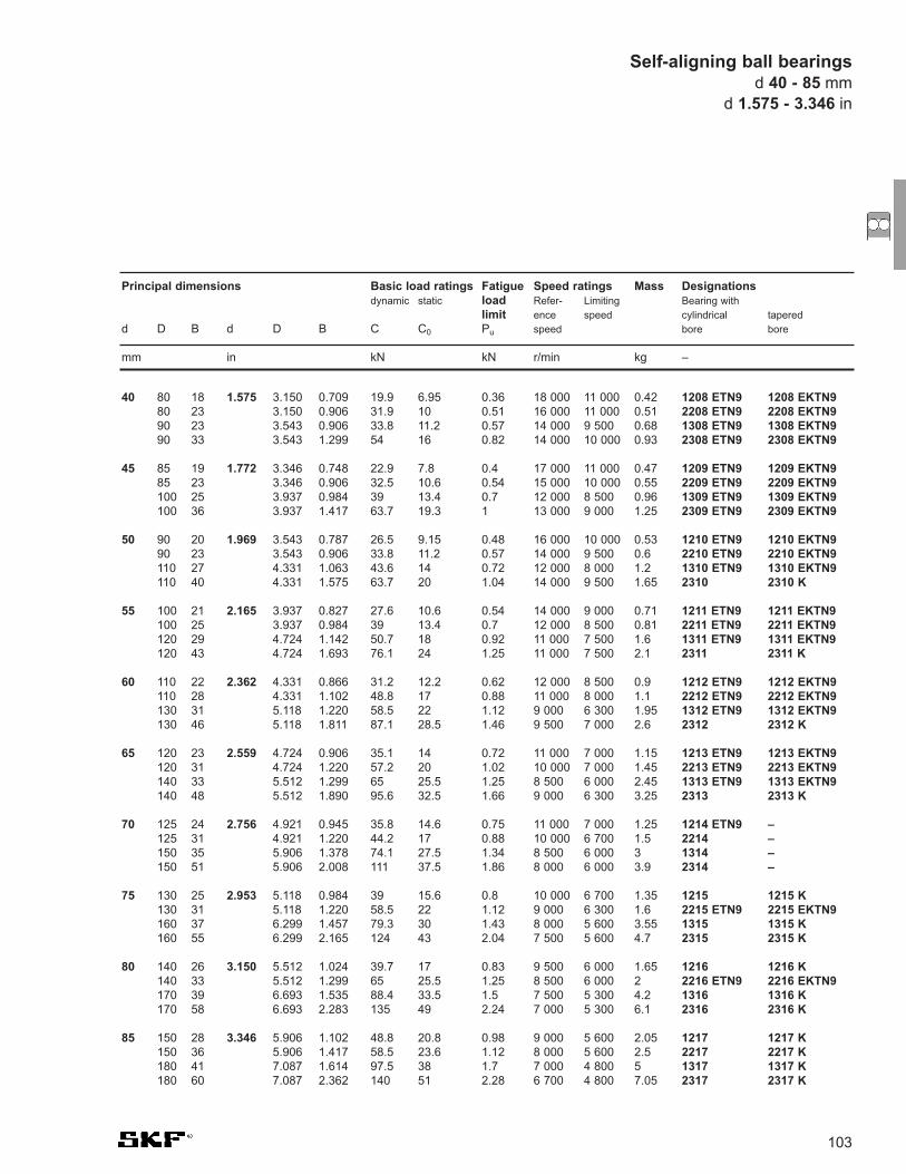
103
40 80 18 1.575 3.150 0.709 19.9 6.95 0.36 18 000 11 000 0.42 1208 ETN9 1208 EKTN980 23 3.150 0.906 31.9 10 0.51 16 000 11 000 0.51 2208 ETN9 2208 EKTN990 23 3.543 0.906 33.8 11.2 0.57 14 000 9 500 0.68 1308 ETN9 1308 EKTN990 33 3.543 1.299 54 16 0.82 14 000 10 000 0.93 2308 ETN9 2308 EKTN9
45 85 19 1.772 3.346 0.748 22.9 7.8 0.4 17 000 11 000 0.47 1209 ETN9 1209 EKTN985 23 3.346 0.906 32.5 10.6 0.54 15 000 10 000 0.55 2209 ETN9 2209 EKTN9100 25 3.937 0.984 39 13.4 0.7 12 000 8 500 0.96 1309 ETN9 1309 EKTN9100 36 3.937 1.417 63.7 19.3 1 13 000 9 000 1.25 2309 ETN9 2309 EKTN9
50 90 20 1.969 3.543 0.787 26.5 9.15 0.48 16 000 10 000 0.53 1210 ETN9 1210 EKTN990 23 3.543 0.906 33.8 11.2 0.57 14 000 9 500 0.6 2210 ETN9 2210 EKTN9110 27 4.331 1.063 43.6 14 0.72 12 000 8 000 1.2 1310 ETN9 1310 EKTN9110 40 4.331 1.575 63.7 20 1.04 14 000 9 500 1.65 2310 2310 K
55 100 21 2.165 3.937 0.827 27.6 10.6 0.54 14 000 9 000 0.71 1211 ETN9 1211 EKTN9100 25 3.937 0.984 39 13.4 0.7 12 000 8 500 0.81 2211 ETN9 2211 EKTN9120 29 4.724 1.142 50.7 18 0.92 11 000 7 500 1.6 1311 ETN9 1311 EKTN9120 43 4.724 1.693 76.1 24 1.25 11 000 7 500 2.1 2311 2311 K
60 110 22 2.362 4.331 0.866 31.2 12.2 0.62 12 000 8 500 0.9 1212 ETN9 1212 EKTN9110 28 4.331 1.102 48.8 17 0.88 11 000 8 000 1.1 2212 ETN9 2212 EKTN9130 31 5.118 1.220 58.5 22 1.12 9 000 6 300 1.95 1312 ETN9 1312 EKTN9130 46 5.118 1.811 87.1 28.5 1.46 9 500 7 000 2.6 2312 2312 K
65 120 23 2.559 4.724 0.906 35.1 14 0.72 11 000 7 000 1.15 1213 ETN9 1213 EKTN9120 31 4.724 1.220 57.2 20 1.02 10 000 7 000 1.45 2213 ETN9 2213 EKTN9140 33 5.512 1.299 65 25.5 1.25 8 500 6 000 2.45 1313 ETN9 1313 EKTN9140 48 5.512 1.890 95.6 32.5 1.66 9 000 6 300 3.25 2313 2313 K
70 125 24 2.756 4.921 0.945 35.8 14.6 0.75 11 000 7 000 1.25 1214 ETN9 –125 31 4.921 1.220 44.2 17 0.88 10 000 6 700 1.5 2214 –150 35 5.906 1.378 74.1 27.5 1.34 8 500 6 000 3 1314 –150 51 5.906 2.008 111 37.5 1.86 8 000 6 000 3.9 2314 –
75 130 25 2.953 5.118 0.984 39 15.6 0.8 10 000 6 700 1.35 1215 1215 K 130 31 5.118 1.220 58.5 22 1.12 9 000 6 300 1.6 2215 ETN9 2215 EKTN9160 37 6.299 1.457 79.3 30 1.43 8 000 5 600 3.55 1315 1315 K160 55 6.299 2.165 124 43 2.04 7 500 5 600 4.7 2315 2315 K
80 140 26 3.150 5.512 1.024 39.7 17 0.83 9 500 6 000 1.65 1216 1216 K140 33 5.512 1.299 65 25.5 1.25 8 500 6 000 2 2216 ETN9 2216 EKTN9170 39 6.693 1.535 88.4 33.5 1.5 7 500 5 300 4.2 1316 1316 K170 58 6.693 2.283 135 49 2.24 7 000 5 300 6.1 2316 2316 K
85 150 28 3.346 5.906 1.102 48.8 20.8 0.98 9 000 5 600 2.05 1217 1217 K150 36 5.906 1.417 58.5 23.6 1.12 8 000 5 600 2.5 2217 2217 K180 41 7.087 1.614 97.5 38 1.7 7 000 4 800 5 1317 1317 K180 60 7.087 2.362 140 51 2.28 6 700 4 800 7.05 2317 2317 K
Principal dimensions Basic load ratings Fatigue Speed ratings Mass Designationsdynamic static load Refer- Limiting Bearing with
limit ence speed cylindrical taperedd D B d D B C C0 Pu speed bore bore
mm in kN kN r/min kg –
Self-aligning ball bearingsd 40 - 85 mm
d 1.575 - 3.346 in

104
Self-aligning ball bearingsd 90 - 240 mmd 3.543 - 9.449 in
90 160 30 3.543 6.299 1.181 57.2 23.6 1.08 8 500 5 300 2.5 1218 1218 K160 40 6.299 1.575 70.2 28.5 1.32 7 500 5 300 3.4 2218 2218 K190 43 7.480 1.693 117 44 1.93 6 700 4 500 5.8 1318 1318 K190 64 7.480 2.520 153 57 2.5 6 300 4 500 8.45 2318 M 2318 KM
95 170 32 3.740 6.693 1.260 63.7 27 1.2 8 000 5 000 3.1 1219 1219 K170 43 6.693 1.693 83.2 34.5 1.53 7 000 5 000 4.1 2219 M 2219 KM200 45 7.874 1.772 133 51 2.16 6 300 4 300 6.7 1319 1319 K200 67 7.874 2.638 165 64 2.75 6 000 4 500 9.8 2319 M –
100 180 34 3.937 7.087 1.339 68.9 30 1.29 7 500 4 800 3.7 1220 1220 K180 46 7.087 1.811 97.5 40.5 1.76 6 700 4 800 5 2220 M 2220 KM215 47 8.465 1.850 143 57 2.36 6 000 4 000 8.3 1320 1320 K215 73 8.465 2.874 190 80 3.25 5 600 4 000 12.5 2320 M 2320 KM
110 200 38 4.331 7.874 1.496 88.4 39 1.6 6 700 4 300 5.15 1222 1222 K200 53 7.874 2.087 124 52 2.12 6 000 4 300 7.1 2222 M 2222 KM240 50 9.449 1.969 163 72 2.75 5 300 3 600 12 1322 M 1322 KM
120 215 42 4.724 8.465 1.654 119 53 2.12 6 300 4 000 6.75 1224 M 1224 KM
130 230 46 5.118 9.055 1.811 127 58.5 2.24 5 600 3 600 8.3 1226 M
150 225 56 5.906 8.858 2.205 57.2 23.6 0.88 5 600 3 400 7.5 13030
180 280 74 7.087 11.024 2.913 95.6 40 1.34 4 500 2 800 16 13036
200 280 60 7.874 11.024 2.362 60.5 29 0.97 4 300 2 600 10.7 13940
220 300 60 8.661 11.811 2.362 60.5 30.5 0.97 3 800 2 400 11 13944
240 320 60 9.449 12.598 2.362 60.5 32 0.98 3 800 2 200 11.3 13948
Principal dimensions Basic load ratings Fatigue Speed ratings Mass Designationsdynamic static load Refer- Limiting Bearing with
limit ence speed cylindrical taperedd D B d D B C C0 Pu speed bore bore
mm in kN kN r/min kg –
D
B
d

105
10 30 14 0.394 1.181 0.551 5.53 1.18 0.06 17 000 0.048 2200 E-2RS1TN9 –
12 32 14 0.472 1.260 0.551 6.24 1.43 0.08 16 000 0.053 2201 E-2RS1TN9 –
15 35 14 0.591 1.378 0.551 7.41 1.76 0.09 14 000 0.058 2202 E-2RS1TN9 –42 17 1.654 0.669 10.8 2.6 0.14 12 000 0.11 2302 E-2RS1TN9 –
17 40 16 0.669 1.575 0.630 8.84 2.2 0.12 12 000 0.089 2203 E-2RS1TN9 –47 19 1.850 0.748 12.7 3.4 0.18 11 000 0.16 2303 E-2RS1TN9 –
20 47 18 0.787 1.850 0.709 12.7 3.4 0.18 10 000 0.14 2204 E-2RS1TN9 –52 21 2.047 0.827 14.3 4 0.21 9 000 0.21 2304 E-2RS1TN9 –
25 52 18 0.984 2.047 0.709 14.3 4 0.21 9 000 0.16 2205 E-2RS1TN9 2205 E-2RS1KTN962 24 2.441 0.945 19 5.4 0.28 7 500 0.34 2305 E-2RS1TN9 –
30 62 20 1.181 2.441 0.787 15.6 4.65 0.24 7 500 0.26 2206 E-2RS1TN9 2206 E-2RS1KTN972 27 2.835 1.063 22.5 6.8 0.36 6 700 0.51 2306 E-2RS1TN9 –
35 72 23 1.378 2.835 0.906 19 6 0.31 6 300 0.41 2207 E-2RS1TN9 2207 E-2RS1KTN980 31 3.150 1.220 26.5 8.5 0.43 5 600 0.7 2307 E-2RS1TN9 –
40 80 23 1.575 3.150 0.906 19.9 6.95 0.36 5 600 0.5 2208 E-2RS1TN9 2208 E-2RS1KTN990 33 3.543 1.299 33.8 11.2 0.57 5 000 0.96 2308 E-2RS1TN9 –
45 85 23 1.772 3.346 0.906 22.9 7.8 0.4 5 300 0.53 2209 E-2RS1TN9 2209 E-2RS1KTN9100 36 3.937 1.417 39 13.4 0.7 4 500 1.3 2309 E-2RS1TN9 –
50 90 23 1.969 3.543 0.906 22.9 8.15 0.42 4 800 0.57 2210 E-2RS1TN9 2210 E-2RS1KTN9110 40 4.331 1.575 43.6 14 0.72 4 000 1.65 2310 E-2RS1TN9 –
55 100 25 2.165 3.937 0.984 27.6 10.6 0.54 4 300 0.79 2211 E-2RS1TN9 2211 E-2RS1KTN9
60 110 28 2.362 4.331 1.102 31.2 12.2 0.62 3 800 1.05 2212 E-2RS1TN9 –
65 120 31 2.559 4.724 1.220 35.1 14 0.72 3 600 1.4 2213 E-2RS1TN9 2213 E-2RS1KTN9
70 125 31 2.756 4.921 1.220 35.8 14.6 0.75 3 400 1.45 2214 E-2RS1TN9 –
Principal dimensions Basic load ratings Fatigue Limiting Mass Designationsdynamic static load speed Bearing with
limit cylindrical taperedd D B d D B C C0 Pu bore bore
mm in kN kN r/min kg –
Sealed self-aligning ball bearingsd 10 - 70 mm
d 0.394 - 2.756 in
D
B
d

106
Self-aligning ball bearings with extended inner ringd 20 - 60 mmd 0.787 - 2.362 in
20 47 14 40 0.787 1.850 0.551 1.575 12.7 3.40 0.18 9 000 0.18 11204 ETN9
25 52 15 44 0.984 2.047 0.591 1.732 14.3 4.00 0.21 8 000 0.22 11205 ETN9
30 62 16 48 1.181 2.441 0.630 1.890 15.6 4.65 0.24 6 700 0.35 11206 TN9
35 72 17 52 1.378 2.835 0.669 2.047 15.9 5.10 0.27 5 600 0.54 11207 TN9
40 80 18 56 1.575 3.150 0.709 2.205 19.0 6.55 0.34 5 000 0.72 11208 TN9
45 85 19 58 1.772 3.346 0.748 2.283 21.6 7.35 0.38 4 500 0.77 11209 TN9
50 90 20 58 1.969 3.543 0.787 2.283 22.9 8.15 0.42 4 300 0.85 11210 TN9
60 110 22 62 2.362 4.331 0.866 2.441 30.2 11.6 0.6 3 400 1.15 11212 TN9
Principal dimensions Basic load ratings Fatigue Limiting Mass Designationdynamic static load speed
limitd D C B d D C B C C0 Pu
mm in kN kN r/min kg –
D d
B
C
79

107
N 310 EC M / C3 V W23B
12
34
5
Cylindrical RollerBearings
6
1. Basic Design
N Two integral flanges on innerring, flangeless outer ring
NCF Full complement, two flanges oninner ring, one flange on outerring, with snap ring
NJ One integral flange on inner ring,two flanges on outer ring
NJG Full complement with one flangeon inner ring and two flanges onouter
NNC Double row CRB with one outerring integral flange and oneflange ring
NNCF Two-row, full complement, three flanges on inner ring, one flangeon outer ring with snap ring
NNCL Double row CRB with no outerring integral flanges, onecentrally located snap ring
NNF Two-row, full complement
NU Two integral flanges on outerring, flangeless inner ring
NUP Two integral flanges on outerring, one integral flange on innerring and one loose flange on inner ring
RN N type without outer ring
RNU NU type without inner ring
2. Internal Design
EC Increased capacity plusimproved roller end to flangecontact
3. Cage Designations
J Pressed steel cage, rollingelement centred
M Machined brass cage, rollingelement centred
MA Machined brass cage, flangeouter ring centred
ML One piece form turned, windowtype brass cage, ring centred
M2 Solid brass drilled cage, rollerguided
P Injection moulded cage offiberglass reinforced polyamide.
PH PEEK, hi-temp polyether etherkeytone cage
4. Radial Internal Clearance
C1 Clearance < C2
C2 Clearance < Normal
C0,CN Normal clearance (no symbolshown)
C3 Clearance > Normal
C4 Clearance > C3
5. Variations
BV V + surface treated rollers
2LS Two land riding contact seals
V Full complement bearing withoutcage
6. Special Features
VA 301 Special bearing specifications fortraction motors
VA 3091 VA 301 + VL 0241
VL 0241 Aluminum oxide coating oninner ring for electrical insulation
VQ 015 Inner ring with crowned racewayfor increased permissible misalignment
W23B Special features for tractionmotor bearings

108
Boundary Dimensions In accordance with ISO 15-1998
Tolerances Boundary dimensions RBEC 1 (normal)Running accuracy RBEC 3 (P6)
Heat Stabilization 302°F (150°C)
Misalignment 4 minutes of arc for series N200, 300, 400 and 1000, 18003 minutes of arc for series N2200 and 23002900, 3000
Cage MaterialStandard Polyamide (P)Optional Machined brass (M) and Pressed steel (J)
Axial Load – max Contact SKF Application Engineering
Seals 2LS seals on NNF series only
Technical Features
Single Row Cylindrical Roller Bearing(data tables on page 112)
Full Complement, Single RowCylindrical Roller Bearing(data tables on page 128)
Full Complement, Double RowCylindrical Roller Bearing(data tables on page 133)
Cylindrical roller bearings

109
Bore Radial internal clearancediameterd C2 Normal C3 C4over incl. min max min max min max min max min max min max min max min maxmm µm in µm in µm in µm in
- 24 0 25 0.0000 0.0010 20 45 0.0008 0.0018 35 60 0.0014 0.0024 50 75 0.0020 0.003024 30 0 25 0.0000 0.0010 20 45 0.0008 0.0018 35 60 0.0014 0.0024 50 75 0.0020 0.003030 40 5 30 0.0002 0.0012 25 50 0.0010 0.0020 45 70 0.0018 0.0028 60 85 0.0024 0.0033
40 50 5 35 0.0002 0.0014 30 60 0.0012 0.0024 50 80 0.0020 0.0031 70 100 0.0028 0.003950 65 10 40 0.0004 0.0016 40 70 0.0016 0.0028 60 90 0.0024 0.0035 80 110 0.0031 0.004365 80 10 45 0.0004 0.0018 40 75 0.0016 0.0030 65 100 0.0026 0.0039 90 125 0.0035 0.0049
80 100 15 50 0.0006 0.0020 50 85 0.0020 0.0033 75 110 0.0030 0.0043 105 140 0.0041 0.0055100 120 15 55 0.0006 0.0022 50 90 0.0020 0.0035 85 125 0.0033 0.0049 125 165 0.0049 0.0065120 140 15 60 0.0006 0.0024 60 105 0.0024 0.0041 100 145 0.0039 0.0057 145 190 0.0057 0.0075
140 160 20 70 0.0008 0.0028 70 120 0.0028 0.0047 115 165 0.0045 0.0065 165 215 0.0065 0.0085160 180 25 75 0.0010 0.0030 75 125 0.0003 0.0049 120 170 0.0047 0.0067 170 220 0.0067 0.0087180 200 35 90 0.0014 0.0035 90 145 0.0035 0.0057 140 195 0.0055 0.0077 195 250 0.0077 0.0098
200 225 45 105 0.0018 0.0041 105 165 0.0041 0.0065 160 220 0.0063 0.0087 220 280 0.0087 0.0110225 250 45 110 0.0018 0.0043 110 175 0.0043 0.0069 170 235 0.0067 0.0093 235 300 0.0093 0.0118250 280 55 125 0.0022 0.0049 125 195 0.0049 0.0077 190 260 0.0075 0.0102 260 330 0.0102 0.0130
280 315 55 130 0.0022 0.0051 130 205 0.0051 0.0081 200 275 0.0079 0.0108 275 350 0.0108 0.0138315 355 65 145 0.0026 0.0057 145 225 0.0057 0.0089 225 305 0.0089 0.0120 305 385 0.0120 0.0152355 400 100 190 0.0039 0.0075 190 280 0.0075 0.0110 280 370 0.0110 0.0146 370 460 0.0146 0.0181
400 450 110 210 0.0043 0.0083 210 310 0.0083 0.0122 310 410 0.0122 0.0161 410 510 0.0161 0.0201450 500 110 220 0.0043 0.0087 220 330 0.0087 0.0130 330 440 0.0130 0.0173 440 550 0.0173 0.0217500 560 120 240 0.0047 0.0094 240 360 0.0094 0.0142 360 480 0.0142 0.0189 480 600 0.0189 0.0236
560 630 140 260 0.0055 0.0102 260 380 0.0102 0.0150 380 500 0.0150 0.0197 500 620 0.0197 0.0244630 710 145 285 0.0057 0.0112 285 425 0.0112 0.0167 425 565 0.0167 0.0222 565 705 0.0222 0.0278710 800 150 310 0.0059 0.0122 310 470 0.0122 0.0185 470 630 0.0185 0.0248 630 790 0.0248 0.0311
Table 1 Radial internal clearance of cylindrical roller bearings
InternalClearance Radial internal clearanceSKF single row cylindrical roller bearings are produced with Normal radial internalclearance as standard; the majority of thebearings are also available with C3 radialinternal clearance and some with theappreciably greater C4 clearance.
The values for the clearance correspond toDIN 620, Part 4 for the size range coveredby this standard and are given in table 1.The values apply to bearings beforemounting and under zero measuring load.
SKF full complement cylindrical rollerbearings are manufactured with Normal orC3 radial internal clearance as standard.The values for the clearance limitscorrespond to ISO and are shown in table 1.
Special SolutionsUsing CylindricalRoller BearingsSKF also manufactures:
• precision single and double row cylindrical roller bearings for machinetool applications
• double and multi-row cylindrical roller bearings for rolling mill and other heavy engineering applications
• special traction motor roller bearings forrailroad applications
Details on these special solutionproducts are available in other SKFpublications, which can be suppliedupon request.
Axial internal clearanceCylindrical roller bearings of the NUP typecan serve to locate shafts in both directions.Axial internal clearance according to table 2.
The values given in table 2 for axialinternal clearance should be considered asguideline values. Because of roller tilting during measurement of the axial internalclearance, increases in the clearance arepossible. These correspond:
• for bearings of series 10, 2, 3 and 4 toapproximately the radial internalclearance and
• for bearings of series 22 and 23 to approximately 2/3 of the radial internal clearance
Cylindrical roller bearings

110
Bore Axial internal clearance diameterd NUP 2 NUP 3 NUP 4 NUP 22 NUP 23
min max min max min max min max min max min max min max min max min max min maxmm µm in µm in µm in µm in µm in
15 - - - - - - - - - - - - - - - - - - - -17 37 140 0.0015 0.0055 37 140 0.0015 0.0055 - - - - 37 140 0.0015 0.0055 47 155 0.0019 0.006120 37 140 0.0015 0.0000 37 140 0.0015 0.0055 - - - - 47 155 0.0019 0.0061 47 155 0.0019 0.0061
25 37 140 0.0015 0.0055 47 155 0.0019 0.0061 - - - - 47 155 0.0019 0.0061 47 155 0.0019 0.006130 37 140 0.0015 0.0055 47 155 0.0019 0.0061 - - - - 47 155 0.0019 0.0061 47 155 0.0019 0.006135 47 155 0.0019 0.0061 47 155 0.0019 0.0061 55 155 0.0022 0.0061 47 155 0.0019 0.0061 62 180 0.0024 0.0071
40 47 155 0.0019 0.0061 47 155 0.0019 0.0061 55 155 0.0022 0.0061 47 155 0.0019 0.0061 62 180 0.0024 0.007145 47 155 0.0019 0.0061 47 155 0.0019 0.0061 55 155 0.0022 0.0061 47 155 0.0019 0.0061 62 180 0.0024 0.007150 47 155 0.0019 0.0061 47 155 0.0019 0.0061 70 185 0.0028 0.0073 47 155 0.0019 0.0061 62 180 0.0024 0.0071
55 47 155 0.0019 0.0061 47 155 0.0019 0.0061 70 185 0.0028 0.0073 47 155 0.0019 0.0061 62 180 0.0024 0.007160 47 155 0.0019 0.0061 62 180 0.0024 0.0071 70 185 0.0028 0.0073 62 180 0.0024 0.0071 87 230 0.0034 0.009165 47 155 0.0019 0.0061 62 180 0.0024 0.0071 70 185 0.0028 0.0073 62 180 0.0024 0.0071 87 230 0.0034 0.0091
70 47 155 0.0019 0.0061 62 180 0.0024 0.0071 70 185 0.0028 0.0073 62 180 0.0024 0.0071 87 230 0.0034 0.009175 47 155 0.0019 0.0061 62 180 0.0024 0.0071 70 185 0.0028 0.0073 62 180 0.0024 0.0071 87 230 0.0034 0.009180 47 155 0.0019 0.0061 62 180 0.0024 0.0071 - - - - 62 180 0.0024 0.0071 87 230 0.0034 0.0091
85 62 180 0.0024 0.0071 62 180 0.0024 0.0071 - - - - 62 180 0.0024 0.0071 87 230 0.0034 0.009190 62 180 0.0024 0.0071 62 180 0.0024 0.0071 - - - - 62 180 0.0024 0.0071 87 230 0.0034 0.009195 62 180 0.0024 0.0071 62 180 0.0024 0.0071 - - - - 62 180 0.0024 0.0071 87 230 0.0034 0.0091
100 62 180 0.0024 0.0071 87 230 0.0034 0.0091 - - - - 87 230 0.0034 0.0091 120 315 0.0047 0.0124105 62 180 0.0024 0.0071 - - - - - - - - 87 230 0.0034 0.0091 120 315 0.0047 0.0124110 62 180 0.0024 0.0071 87 230 0.0034 0.0091 - - - - 87 230 0.0034 0.0091 120 315 0.0047 0.0124
120 62 180 0.0024 0.0071 87 230 0.0034 0.0091 - - - - 87 230 0.0034 0.0091 120 315 0.0047 0.0124130 62 180 0.0024 0.0071 87 230 0.0034 0.0091 - - - - 87 230 0.0034 0.0091 120 315 0.0047 0.0124140 62 180 0.0024 0.0071 87 230 0.0034 0.0091 - - - - 87 230 0.0034 0.0091 120 315 0.0047 0.0124
150 62 180 0.0024 0.0071 87 230 0.0034 0.0091 - - - - 87 230 0.0034 0.0091 120 315 0.0047 0.0124160 87 230 0.0034 0.0091 - - - - - - - - - - - - - - - -170 87 230 0.0034 0.0091 - - - - - - - - - - - - - - - -
180 87 230 0.0034 0.0091 - - - - - - - - - - - - - - - -190 87 230 0.0034 0.0091 - - - - - - - - - - - - - - - -200 87 230 0.0034 0.0091 - - - - - - - - - - - - - - - -
220 95 230 0.0037 0.0091 - - - - - - - - - - - - - - - -
Table 2 Axial internal clearance of single row cylindrical roller bearings
Cylindrical roller bearings
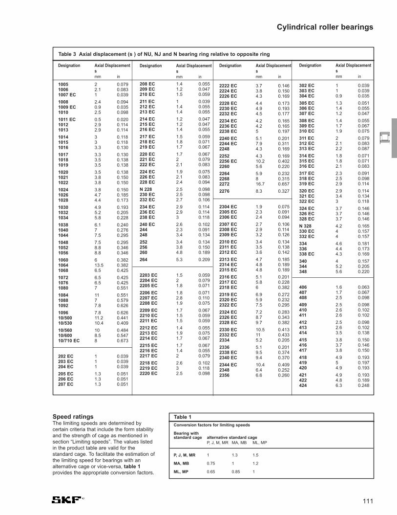
111
Table 3 Axial displacement (s ) of NU, NJ and N bearing ring relative to opposite ring
Designation Axial Displacementsmm in
1005 2 0.0791006 2.1 0.0831007 EC 1 0.039
1008 2.4 0.0941009 EC 0.9 0.0351010 2.5 0.098
1011 EC 0.5 0.0201012 2.9 0.1141013 2.9 0.114
1014 3 0.1181015 3 0.1181016 3.3 0.130
1017 3.3 0.1301018 3.5 0.1381019 3.5 0.138
1020 3.5 0.1381021 3.8 0.1501022 3.8 0.150
1024 3.8 0.1501026 4.7 0.1851028 4.4 0.173
1030 4.9 0.1931032 5.2 0.2051034 5.8 0.228
1038 6.1 0.2401040 7 0.2761044 7.5 0.295
1048 7.5 0.2951052 8.8 0.3461056 8.8 0.346
1060 6 0.3821064 13.5 0.3821068 6.5 0.425
1072 6.5 0.4251076 6.5 0.4251080 7 0.551
1084 11 0.5511088 7 0.5791092 7.8 0.626
1096 7.8 0.62610/500 11.2 0.44110/530 10.4 0.409
10/560 10 0.48410/600 8.5 0.54710/710 EC 8 0.673
202 EC 1 0.039203 EC 1 0.039204 EC 1 0.039
205 EC 1.3 0.051206 EC 1.3 0.051207 EC 1.3 0.051
Designation Axial Displacementsmm in
208 EC 1.4 0.055209 EC 1.2 0.047210 EC 1.5 0.059
211 EC 1 0.039212 EC 1.4 0.055213 EC 1.4 0.055
214 EC 1.2 0.047215 EC 1.2 0.047216 EC 1.4 0.055
217 EC 1.5 0.059218 EC 1.8 0.071219 EC 1.7 0.067
220 EC 1.7 0.067221 EC 2 0.079222 EC 2.1 0.083
224 EC 1.9 0.075226 EC 2.1 0.083228 EC 2.4 0.094
N 228 2.5 0.098230 EC 2.5 0.098232 EC 2.7 0.106
234 EC 2.9 0.114236 EC 2.9 0.114238 EC 3 0.118
240 EC 2.6 0.102244 2.3 0.091248 3.4 0.134
252 3.4 0.134256 3.8 0.150260 4.8 0.189
264 5.3 0.209
2203 EC 1.5 0.0592204 EC 2 0.0792205 EC 1.8 0.071
2206 EC 1.8 0.0712207 EC 2.8 0.1102208 EC 1.9 0.075
2209 EC 1.7 0.0672210 EC 1.5 0.0592211 EC 1.5 0.059
2212 EC 1.4 0.0552213 EC 1.9 0.0752214 EC 1.7 0.067
2215 EC 1.7 0.0672216 EC 1.4 0.0552217 EC 2 0.079
2218 EC 2.6 0.1022219 EC 3 0.1182220 EC 2.5 0.098
Designation Axial Displacementsmm in
2222 EC 3.7 0.1462224 EC 3.8 0.1502226 EC 4.3 0.169
2228 EC 4.4 0.1732230 EC 4.9 0.1932232 EC 4.5 0.177
2234 EC 4.2 0.1652236 EC 4.2 0.1652238 EC 5 0.197
2240 EC 5.1 0.2012244 EC 7.9 0.3112248 4.3 0.169
2252 4.3 0.1692256 EC 10.2 0.4022260 5.6 0.220
2264 5.9 0.2322268 8 0.3152272 16.7 0.657
2276 8.3 0.327
2304 EC 1.9 0.0752305 EC 2.3 0.0912306 EC 2.4 0.094
2307 EC 2.7 0.1062308 EC 2.9 0.1142309 EC 3.2 0.126
2310 EC 3.4 0.1342311 EC 3.5 0.1382312 EC 3.6 0.142
2313 EC 4.7 0.1852314 EC 4.8 0.1892315 EC 4.8 0.189
2316 EC 5.1 0.2012317 EC 5.8 0.2282318 EC 6 0.382
2319 EC 6.9 0.2722320 EC 5.9 0.2322322 EC 7.5 0.295
2324 EC 7.2 0.2832326 EC 8.7 0.3432328 EC 9.7 0.382
2330 EC 10.5 0.4132332 EC 11 0.4332334 5.2 0.205
2336 5.1 0.2012338 EC 9.5 0.3742340 EC 9.4 0.370
2344 EC 10.4 0.4092348 6.4 0.2522356 6.6 0.260
Designation Axial Displacementsmm in
302 EC 1 0.039303 EC 1 0.039304 EC 0.9 0.035
305 EC 1.3 0.051306 EC 1.4 0.055307 EC 1.2 0.047
308 EC 1.4 0.055309 EC 1.7 0.067310 EC 1.9 0.075
311 EC 2 0.079312 EC 2.1 0.083313 EC 2.2 0.087
314 EC 1.8 0.071315 EC 1.8 0.071316 EC 2.1 0.083
317 EC 2.3 0.091318 EC 2.5 0.098319 EC 2.9 0.114
320 EC 2.9 0.114321 EC 3.4 0.134322 EC 3 0.118
324 EC 3.7 0.146326 EC 3.7 0.146328 EC 3.7 0.146
N 328 4.2 0.165330 EC 4 0.157332 EC 4 0.157
334 4.6 0.181336 4.4 0.173338 EC 4.3 0.169
340 4 0.157344 5.2 0.205348 5.6 0.220
406 1.6 0.063407 1.7 0.067408 2.5 0.098
409 2.5 0.098410 2.6 0.102411 2.6 0.102
412 2.5 0.098413 2.6 0.102414 3.5 0.138
415 3.8 0.150416 3.7 0.146417 3.8 0.150
418 4.9 0.193419 5 0.197420 4.9 0.193
421 4.9 0.193422 4.8 0.189424 6.3 0.248
Cylindrical roller bearings
Conversion factors for limiting speeds
Bearing withstandard cage alternative standard cage
P, J, M, MR MA, MB ML, MP
P, J, M, MR 1 1.3 1.5
MA, MB 0.75 1 1.2
ML, MP 0.65 0.85 1
Table 1Speed ratingsThe limiting speeds are determined bycertain criteria that include the form stabilityand the strength of cage as mentioned insection “Limiting speeds”. The values listedin the product table are valid for thestandard cage. To facilitate the estimation ofthe limiting speed for bearings with analternative cage or vice-versa, table 1provides the appropriate conversion factors.

D
B
d d
NU NJ NUP N
Principal dimensions Basic load Fatigue Speed ratings Mass Designationsratings load Refer- Limiting Bearing Bearing with Alternativedynamic static limit ence speed with standard cage standard
d D B d D B C C0 Pu speed standard cage cage designs1)
mm in kN kN r/min kg –
* SKF Explorer bearing 1) When ordering bearings with an alternative standard cage, the suffix of thestandard cage has to be replaced by the suffix of the cage in question, e.g.NU 203 ECP becomes NU 203 ECML (for speed ratings see page 111)
2) HJ angle ringsare available
112
Single row cylindrical roller bearingsd 15 - 25 mmd 0.591 - 0.984 in
NU 202 ECP –NJ 202 ECP –
NU 203 ECP MLNJ 203 ECP MLNUP 203 ECP MLN 203 ECP
NU 2203 ECP –NJ 2203 ECP –NUP 2203 ECP –
NU 303 ECP –NJ 303 ECP –N 303 ECP –
NU 204 ECP MLNJ 204 ECP MLNUP 204 ECP MLN 204 ECP –
NU 2204 ECP –NJ 2204 ECP –
*NU 304 ECP –*NJ 304 ECP –*NUP 304 ECP –*N 304 ECP –
*NU 2304 ECP –*NJ 2304 ECP –*NUP 2304 ECP –
NU 1005 –
NU 205 ECP J. MLNJ 205 ECP J. MLNUP 205 ECP MLN 205 ECP –
NU 2205 ECP MLNJ 2205 ECP MLNUP 2205 ECP ML
*NU 305 ECP J. ML*NJ 305 ECP J. ML*NUP 305 ECP J. ML*N 305 ECP –
1.378 0.433 12.5 10.2 1.22 22 000 26 000 0.0471.378 0.433 12.5 10.2 1.22 22 000 26 000 0.049
1.575 0.472 17.2 14.3 1.73 19 000 22 000 0.0681.575 0.472 17.2 14.3 1.73 19 000 22 000 0.071.575 0.472 17.2 14.3 1.73 19 000 22 000 0.0731.575 0.472 17.2 14.3 1.73 19 000 22 000 0.066
1.575 0.630 23.8 21.6 2.65 19 000 22 000 0.0921.575 0.630 23.8 21.6 2.65 19 000 22 000 0.0951.575 0.630 23.8 21.6 2.65 19 000 22 000 0.097
1.850 0.551 24.6 20.4 2.55 15 000 20 000 0.121.850 0.551 24.6 20.4 2.55 15 000 20 000 0.121.850 0.551 24.6 20.4 2.55 15 000 20 000 0.12
1.850 0.551 25.1 25.2 2.75 16 000 19 000 0.111.850 0.551 25.1 25.2 2.75 16 000 19 000 0.111.850 0.551 25.1 25.2 2.75 16 000 19 000 0.121.850 0.551 25.1 25.2 2.75 16 000 19 000 0.11
1.850 0.709 29.7 27.5 3.45 16 000 19 000 0.141.850 0.709 29.7 27.5 3.45 16 000 19 000 0.14
2.047 0.591 35.5 26 3.25 15 000 18 000 0.172.047 0.591 35.5 26 3.25 15 000 18 000 0.172.047 0.591 35.5 26 3.25 15 000 18 000 0.162.047 0.591 35.5 26 3.25 15 000 18 000 0.15
2.047 0.827 47.5 38 4.8 14 000 18 000 0.212.047 0.827 47.5 38 4.8 14 000 18 000 0.222.047 0.827 47.5 38 4.8 14 000 18 000 0.22
1.850 0.472 14.2 13.2 1.4 18 000 18 000 0.084
2.047 0.591 28.6 27 3.35 14 000 16 000 0.142.047 0.591 28.6 27 3.35 14 000 16 000 0.152.047 0.591 28.6 27 3.35 14 000 16 000 0.142.047 0.591 28.6 27 3.35 14 000 16 000 0.13
2.047 0.709 34.1 34 4.25 14 000 16 000 0.172.047 0.709 34.1 34 4.25 14 000 16 000 0.182.047 0.709 34.1 34 4.25 14 000 16 000 0.17
2.441 0.669 46.5 36.5 4.55 12 000 15 000 0.282.441 0.669 46.5 36.5 4.55 12 000 15 000 0.292.441 0.669 46.5 36.5 4.55 12 000 15 000 0.252.441 0.669 46.5 36.5 4.55 12 000 15 000 0.24
0.591
0.669
0.787
0.984
35 1135 11
40 1240 1240 1240 12
40 1640 1640 16
47 1447 1447 14
47 1447 1447 1447 14
47 1847 18
52 1552 1552 1552 15
52 2152 2152 21
47 12
52 1552 1552 1552 15
52 1852 1852 18
62 1762 1762 1762 17
15
17
20
25

Single row cylindrical roller bearingsd 25 - 35 mm
d 0.984 - 1.378 in
*NU 2305 ECP J. ML*NJ 2305 ECP ML*NUP 2305 ECP ML
NU 1006 –
*NU 206 ECP J. ML*NJ 206 ECP J. ML*NUP 206 ECP ML*N 206 ECP –
*NU 2206 ECP J. ML*NJ 2206 ECP J. ML*NUP 2206 ECP ML
*NU 306 ECP J. M. ML*NJ 306 ECP J. M. ML*NUP 306 ECP J. M. ML*N 306 ECP –
*NU 2306 ECP ML*NJ 2306 ECP ML*NUP 2306 ECP ML
NU 406 –NJ 406 –
NU 1007 ECP –
*NU 207 ECP J. M. ML*NJ 207 ECP J. M. ML*NUP 207 ECP J. M. ML*N 207 ECP –
*NU 2207 ECP J. ML*NJ 2207 ECP J. ML*NUP 2207 ECP ML
*NU 307 ECP J. M. ML*NJ 307 ECP J. M. ML*NUP 307 ECP J. M. ML*N 307 ECP –
*NU 2307 ECP J*NJ 2307 ECP –*NUP 2307 ECP –
NU 407 –NJ 407 –
2.441 0.945 64 55 6.95 12 000 15 000 0.382.441 0.945 64 55 6.95 12 000 15 000 0.392.441 0.945 64 55 6.95 12 000 15 000 0.38
2.165 0.512 17.9 17.3 1.86 14 000 15 000 0.12
2.441 0.630 44 36.5 4.55 13 000 14 000 0.232.441 0.630 44 36.5 4.55 13 000 14 000 0.242.441 0.630 44 36.5 4.55 13 000 14 000 0.222.441 0.630 44 36.5 4.55 13 000 14 000 0.2
2.441 0.787 55 49 6.1 13 000 14 000 0.262.441 0.787 55 49 6.1 13 000 14 000 0.272.441 0.787 55 49 6.1 13 000 14 000 0.27
2.835 0.748 58.5 48 6.2 11 000 12 000 0.42.835 0.748 58.5 48 6.2 11 000 12 000 0.412.835 0.748 58.5 48 6.2 11 000 12 000 0.382.835 0.748 58.5 48 6.2 11 000 12 000 0.36
2.835 1.063 83 75 9.65 11 000 12 000 0.532.835 1.063 83 75 9.65 11 000 12 000 0.542.835 1.063 83 75 9.65 11 000 12 000 0.55
3.543 0.906 60.5 53 6.8 9 000 11 000 0.753.543 0.906 60.5 53 6.8 9 000 11 000 0.77
2.441 0.551 35.8 38 4.55 12 000 13 000 0.16
2.835 0.669 56 48 6.1 11 000 12 000 0.332.835 0.669 56 48 6.1 11 000 12 000 0.332.835 0.669 56 48 6.1 11 000 12 000 0.312.835 0.669 56 48 6.1 11 000 12 000 0.3
2.835 0.906 69.5 63 8.15 11 000 12 000 0.42.835 0.906 69.5 63 8.15 11 000 12 000 0.412.835 0.906 69.5 63 8.15 11 000 12 000 0.42
3.150 0.827 75 63 8.15 9 500 11 000 0.543.150 0.827 75 63 8.15 9 500 11 000 0.553.150 0.827 75 63 8.15 9 500 11 000 0.513.150 0.827 75 63 8.15 9 500 11 000 0.48
3.150 1.220 106 98 12.7 9 500 11 000 0.723.150 1.220 106 98 12.7 9 500 11 000 0.733.150 1.220 106 98 12.7 9 500 11 000 0.75
3.937 0.984 76.5 69.5 9 8 000 9 500 13.937 0.984 76.5 69.5 9 8 000 9 500 1.05
1.181
1.378
25cont.
30
35
113
62 2462 2462 24
55 13
62 1662 1662 1662 16
62 2062 2062 20
72 1972 1972 1972 19
72 2772 2772 27
90 2390 23
62 14
72 1772 1772 1772 17
72 2372 2372 23
80 2180 2180 2180 21
80 3180 3180 31
100 25100 25
Principal dimensions Basic load Fatigue Speed ratings Mass Designationsratings load Refer- Limiting Bearing Bearing with Alternativedynamic static limit ence speed with standard cage standard
d D B d D B C C0 Pu speed standard cage cage designs1)
mm in kN kN r/min kg –
* SKF Explorer bearing 1) When ordering bearings with an alternative standard cage, the suffix of thestandard cage has to be replaced by the suffix of the cage in question, e.g.NU 203 ECP becomes NU 203 ECML (for speed ratings see page 111)
2) HJ angle ringsare available
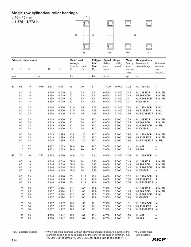
NU 1008 ML –
*NU 208 ECP J. M. ML*NJ 208 ECP J. M. ML*NUP 208 ECP J. M. ML*N 208 ECP –
*NU 2208 ECP J. ML*NJ 2208 ECP J. ML*NUP 2208 ECP J. ML
*NU 308 ECP J. M. ML*NJ 308 ECP J. M. ML*NUP 308 ECP M. ML*N 308 ECP –
*NU 2308 ECP J. M. ML*NJ 2308 ECP J. M. ML*NUP 2308 ECP M. ML
NU 408 –NJ 408 –
NU 1009 ECP –
*NU 209 ECP J. M. ML*NJ 209 ECP J. M. ML*NUP 209 ECP J. M. ML*N 209 ECP –
*NU 2209 ECP J*NJ 2209 ECP J*NUP 2209 ECP –
*NU 309 ECP J. M. ML*NJ 309 ECP J. M. ML*NUP 309 ECP J. ML*N 309 ECP –
*NU 2309 ECP ML*NJ 2309 ECP ML*NUP 2309 ECP ML
NU 409 –NJ 409 –
2.677 0.591 25.1 26 3 11 000 18 000 0.22
3.150 0.709 62 53 6.7 9 500 11 000 0.423.150 0.709 62 53 6.7 9 500 11 000 0.433.150 0.709 62 53 6.7 9 500 11 000 0.43.150 0.709 62 53 6.7 9 500 11 000 0.37
3.150 0.906 81.5 75 9.65 9 500 11 000 0.543.150 0.906 81.5 75 9.65 9 500 11 000 0.553.150 0.906 81.5 75 9.65 9 500 11 000 0.56
3.543 0.906 93 78 10.2 8 000 9 500 0.733.543 0.906 93 78 10.2 8 000 9 500 0.753.543 0.906 93 78 10.2 8 000 9 500 0.683.543 0.906 93 78 10.2 8 000 9 500 0.64
3.543 1.299 129 120 15.3 8 000 9 500 0.943.543 1.299 129 120 15.3 8 000 9 500 0.963.543 1.299 129 120 15.3 8 000 9 500 0.98
4.331 1.063 96.8 90 11.6 7 000 8 500 1.44.331 1.063 96.8 90 11.6 7 000 8 500 1.35
2.953 0.630 44.6 52 6.3 9 500 11 000 0.26
3.346 0.748 69.5 64 8.15 9 000 9 500 0.483.346 0.748 69.5 64 8.15 9 000 9 500 0.493.346 0.748 69.5 64 8.15 9 000 9 500 0.453.346 0.748 69.5 64 8.15 9 000 9 500 0.43
3.346 0.906 85 81.5 10.6 9 000 9 500 0.523.346 0.906 85 81.5 10.6 9 000 9 500 0.543.346 0.906 85 81.5 10.6 9 000 9 500 0.55
3.937 0.984 112 100 12.9 7 500 8 500 13.937 0.984 112 100 12.9 7 500 8 500 1.053.937 0.984 112 100 12.9 7 500 8 500 0.953.937 0.984 112 100 12.9 7 500 8 500 0.88
3.937 1.417 160 153 20 7 500 8 500 1.33.937 1.417 160 153 20 7 500 8 500 1.353.937 1.417 160 153 20 7 500 8 500 1.35
4.724 1.142 106 102 13.4 6 700 7 500 1.784.724 1.142 106 102 13.4 6 700 7 500 1.7
1.575
1.772
40
45
Principal dimensions Basic load Fatigue Speed ratings Mass Designationsratings load Refer- Limiting Bearing Bearing with Alternativedynamic static limit ence speed with standard cage standard
d D B d D B C C0 Pu speed standard cage cage designs1)
mm in kN kN r/min kg –
* SKF Explorer bearing 1) When ordering bearings with an alternative standard cage, the suffix of thestandard cage has to be replaced by the suffix of the cage in question, e.g.NU 203 ECP becomes NU 203 ECML (for speed ratings see page 111)
68 15
80 1880 1880 1880 18
80 2380 2380 23
90 2390 2390 2390 23
90 3390 3390 33
110 27110 27
75 16
85 1985 1985 1985 19
85 2385 2385 23
100 25100 25100 25100 25
100 36100 36100 36
120 29120 29
114
Single row cylindrical roller bearingsd 40 - 45 mmd 1.575 - 1.772 in
D
B
d d
NU NJ NUP N
2) HJ angle ringsare available

Single row cylindrical roller bearingsd 50 - 55 mm
d 1.969 - 2.165 in
NU 1010 ECP –
*NU 210 ECP J. M. ML*NJ 210 ECP J. M. ML*NUP 210 ECP J. ML*N 210 ECP –
*NU 2210 ECP J. M. ML*NJ 2210 ECP J. M. ML*NUP 2210 ECP J. ML
*NU 310 ECP J. M. ML*NJ 310 ECP J. M. ML*NUP 310 ECP J. M. ML*N 310 ECP M
*NU 2310 ECP ML*NJ 2310 ECP ML*NUP 2310 ECP ML
NU 410 –NJ 410 –
NU 1011 ECP –
*NU 211 ECP J. M. ML*NJ 211 ECP J. M. ML*NUP 211 ECP J. M. ML*N 211 ECP M
*NU 2211 ECP J. M. ML*NJ 2211 ECP J. M. ML*NUP 2211 ECP J. ML
*NU 311 ECP J. M. ML*NJ 311 ECP J. M. ML*NUP 311 ECP J. M. ML*N 311 ECP M
*NU 2311 ECP ML*NJ 2311 ECP ML*NUP 2311 ECP ML
NU 411 –NJ 411 –
3.150 0.630 46.8 56 6.7 9 000 9 500 0.27
3.543 0.787 73.5 69.5 8.8 8 500 9 000 0.493.543 0.787 73.5 69.5 8.8 8 500 9 000 0.53.543 0.787 73.5 69.5 8.8 8 500 9 000 0.513.543 0.787 73.5 69.5 8.8 8 500 9 000 0.48
3.543 0.906 90 88 11.4 8 500 9 000 0.563.543 0.906 90 88 11.4 8 500 9 000 0.593.543 0.906 90 88 11.4 8 500 9 000 0.59
4.331 1.063 127 112 15 6 700 8 000 1.154.331 1.063 127 112 15 6 700 8 000 1.154.331 1.063 127 112 15 6 700 8 000 1.24.331 1.063 127 112 15 6 700 8 000 1.15
4.331 1.575 186 186 24.5 6 700 8 000 24.331 1.575 186 186 24.5 6 700 8 000 1.754.331 1.575 186 186 24.5 6 700 8 000 1.8
5.118 1.220 130 127 16.6 6 000 7 000 25.118 1.220 130 127 16.6 6 000 7 000 2.05
3.543 0.709 57.2 69.5 8.3 8 000 8 500 0.4
3.937 0.827 96.5 95 12.2 7 500 8 000 0.673.937 0.827 96.5 95 12.2 7 500 8 000 0.673.937 0.827 96.5 95 12.2 7 500 8 000 0.693.937 0.827 96.5 95 12.2 7 500 8 000 0.66
3.937 0.984 114 118 15.3 7 500 8 000 0.793.937 0.984 114 118 15.3 7 500 8 000 0.813.937 0.984 114 118 15.3 7 500 8 000 0.82
4.724 1.142 156 143 18.6 6 000 7 000 1.454.724 1.142 156 143 18.6 6 000 7 000 1.54.724 1.142 156 143 18.6 6 000 7 000 1.554.724 1.142 156 143 18.6 6 000 7 000 1.45
4.724 1.693 232 232 30.5 6 000 7 000 2.254.724 1.693 232 232 30.5 6 000 7 000 2.34.724 1.693 232 232 30.5 6 000 7 000 2.35
5.512 1.299 142 140 18.6 5 600 6 300 2.55.512 1.299 142 140 18.6 5 600 6 300 2.55
1.969
2.165
50
55
115
80 16
90 2090 2090 2090 20
90 2390 2390 23
110 27110 27110 27110 27
110 40110 40110 40
130 31130 31
90 18
100 21100 21100 21100 21
100 25100 25100 25
120 29120 29120 29120 29
120 43120 43120 43
140 33140 33
Principal dimensions Basic load Fatigue Speed ratings Mass Designationsratings load Refer- Limiting Bearing Bearing with Alternativedynamic static limit ence speed with standard cage standard
d D B d D B C C0 Pu speed standard cage cage designs1)
mm in kN kN r/min kg –
* SKF Explorer bearing 1) When ordering bearings with an alternative standard cage, the suffix of thestandard cage has to be replaced by the suffix of the cage in question, e.g.NU 203 ECP becomes NU 203 ECML (for speed ratings see page 111)
2) HJ angle ringsare available
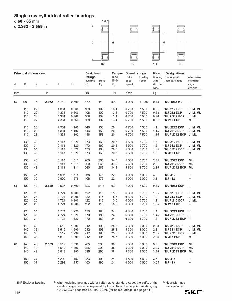
NU 1012 ML –
*NU 212 ECP J. M. ML*NJ 212 ECP J. M. ML*NUP 212 ECP J. ML*N 212 ECP M
*NU 2212 ECP J. M. ML*NJ 2212 ECP J. M. ML*NUP 2212 ECP J. ML
*NU 312 ECP J. M. ML*NJ 312 ECP J. M. ML*NUP 312 ECP J. M. ML*N 312 ECP M
*NU 2312 ECP ML*NJ 2312 ECP ML*NUP 2312 ECP ML
NU 412 –NJ 412 –
NU 1013 ECP –
*NU 213 ECP J. M. ML*NJ 213 ECP J. M. ML*NUP 213 ECP J. ML*N 213 ECP –
*NU 2213 ECP J*NJ 2213 ECP J*NUP 2213 ECP –
*NU 313 ECP J. M. ML*NJ 313 ECP J. M. ML*NUP 313 ECP J. ML*N 313 ECP M
*NU 2313 ECP ML*NJ 2313 ECP ML*NUP 2313 ECP ML
NU 413 –NJ 413 –
3.740 0.709 37.4 44 5.3 8 000 11 000 0.48
4.331 0.866 108 102 13.4 6 700 7 500 0.814.331 0.866 108 102 13.4 6 700 7 500 0.834.331 0.866 108 102 13.4 6 700 7 500 0.864.331 0.866 108 102 13.4 6 700 7 500 0.81
4.331 1.102 146 153 20 6 700 7 500 1.14.331 1.102 146 153 20 6 700 7 500 1.154.331 1.102 146 153 20 6 700 7 500 1.15
5.118 1.220 173 160 20.8 5 600 6 700 1.85.118 1.220 173 160 20.8 5 600 6 700 1.95.118 1.220 173 160 20.8 5 600 6 700 1.955.118 1.220 173 160 20.8 5 600 6 700 1.8
5.118 1.811 260 265 34.5 5 600 6 700 2.755.118 1.811 260 265 34.5 5 600 6 700 2.85.118 1.811 260 265 34.5 5 600 6 700 2.85
5.906 1.378 168 173 22 5 000 6 000 35.906 1.378 168 173 22 5 000 6 000 3.1
3.937 0.709 62.7 81.5 9.8 7 000 7 500 0.45
4.724 0.906 122 118 15.6 6 300 6 700 1.054.724 0.906 122 118 15.6 6 300 6 700 1.074.724 0.906 122 118 15.6 6 300 6 700 1.14.724 0.906 122 118 15.6 6 300 6 700 1.05
4.724 1.220 170 180 24 6 300 6 700 1.44.724 1.220 170 180 24 6 300 6 700 1.454.724 1.220 170 180 24 6 300 6 700 1.5
5.512 1.299 212 196 25.5 5 300 6 000 2.285.512 1.299 212 196 25.5 5 300 6 000 2.35.512 1.299 212 196 25.5 5 300 6 000 2.355.512 1.299 212 196 25.5 5 300 6 000 2.25
5.512 1.890 285 290 38 5 300 6 000 3.35.512 1.890 285 290 38 5 300 6 000 3.355.512 1.890 285 290 38 5 300 6 000 3.45
6.299 1.457 183 190 24 4 800 5 600 3.66.299 1.457 183 190 24 4 800 5 600 3.65
2.362
2.559
2.559
Single row cylindrical roller bearingsd 60 - 65 mmd 2.362 - 2.559 in
60
65
65
Principal dimensions Basic load Fatigue Speed ratings Mass Designationsratings load Refer- Limiting Bearing Bearing with Alternativedynamic static limit ence speed with standard cage standard
d D B d D B C C0 Pu speed standard cage cage designs1)
mm in kN kN r/min kg –
95 18
110 22110 22110 22110 22
110 28110 28110 28
130 31130 31130 31130 31
130 46130 46130 46
150 35150 35
100 18
120 23120 23120 23120 23
120 31120 31120 31
140 33140 33140 33140 33
140 48140 48140 48
160 37160 37
* SKF Explorer bearing 1) When ordering bearings with an alternative standard cage, the suffix of thestandard cage has to be replaced by the suffix of the cage in question, e.g.NU 203 ECP becomes NU 203 ECML (for speed ratings see page 111)
116
D
B
d d
NU NJ NUP N
2) HJ angle ringsare available

Single row cylindrical roller bearingsd 70 - 75 mmd 2.36 - 5.2 in
NU 1014 ECP –
*NU 214 ECP J. M. ML*NJ 214 ECP J. M. ML*NUP 214 ECP M. ML*N 214 ECP –
*NU 2214 ECP J. M. ML*NJ 2214 ECP M. ML*NUP 2214 ECP M. ML
*NU 314 ECP J. M. ML*NJ 314 ECP J. M. ML*NUP 314 ECP M. ML*N 314 ECP M
*NU 2314 ECP ML*NJ 2314 ECP ML*NUP 2314 ECP ML
NU 414 –NJ 414 –
NU 1015 ML –
*NU 215 ECP J. M. ML*NJ 215 ECP J. M. ML*NUP 215 ECP M. ML*N 215 ECP –
*NU 2215 ECP J. ML*NJ 2215 ECP J. ML*NUP 2215 ECP J. ML
*NU 315 ECP J. M. ML*NJ 315 ECP J. M. ML*NUP 315 ECP M. ML*N 315 ECP M
*NU 2315 ECP J. ML*NJ 2315 ECP ML*NUP 2315 ECP ML
NU 415 –NJ 415 –
4.331 0.787 76.5 93 12 6 300 7 000 0.62
4.921 0.945 137 137 18 6 000 6 300 1.154.921 0.945 137 137 18 6 000 6 300 1.154.921 0.945 137 137 18 6 000 6 300 1.24.921 0.945 137 137 18 6 000 6 300 1.15
4.921 1.220 180 193 25.5 6 000 6 300 1.554.921 1.220 180 193 25.5 6 000 6 300 1.554.921 1.220 180 193 25.5 6 000 6 300 1.55
5.906 1.378 236 228 29 4 800 5 600 2.755.906 1.378 236 228 29 4 800 5 600 2.85.906 1.378 236 228 29 4 800 5 600 2.855.906 1.378 236 228 29 4 800 5 600 2.75
5.906 2.008 315 325 41.5 4 800 5 600 45.906 2.008 315 325 41.5 4 800 5 600 4.055.906 2.008 315 325 41.5 4 800 5 600 4.15
7.087 1.654 229 240 30 4 300 5 000 5.257.087 1.654 229 240 30 4 300 5 000 5.35
4.528 0.787 58.3 71 8.5 6 700 10 000 0.74
5.118 0.984 150 156 20.4 5 600 6 000 1.255.118 0.984 150 156 20.4 5 600 6 000 1.35.118 0.984 150 156 20.4 5 600 6 000 1.35.118 0.984 150 156 20.4 5 600 6 000 1.25
5.118 1.220 186 208 27 5 600 6 000 1.65.118 1.220 186 208 27 5 600 6 000 1.65.118 1.220 186 208 27 5 600 6 000 1.65
6.299 1.457 280 265 33.5 4 500 5 300 3.36.299 1.457 280 265 33.5 4 500 5 300 3.356.299 1.457 280 265 33.5 4 500 5 300 3.456.299 1.457 280 265 33.5 4 500 5 300 3.3
6.299 2.165 380 400 50 4 500 5 300 4.96.299 2.165 380 400 50 4 500 5 300 56.299 2.165 380 400 50 4 500 5 300 5.1
7.480 1.772 264 280 34 4 000 4 800 6.757.480 1.772 264 280 34 4 000 4 800 6.9
2.756
2.953
70
75
117
110 20
125 24125 24125 24125 24
125 31125 31125 31
150 35150 35150 35150 35
150 51150 51150 51
180 42180 42
115 20
130 25130 25130 25130 25
130 31130 31130 31
160 37160 37160 37160 37
160 55160 55160 55
190 45190 45
Principal dimensions Basic load Fatigue Speed ratings Mass Designationsratings load Refer- Limiting Bearing Bearing with Alternativedynamic static limit ence speed with standard cage standard
d D B d D B C C0 Pu speed standard cage cage designs1)
mm in kN kN r/min kg –
* SKF Explorer bearing 1) When ordering bearings with an alternative standard cage, the suffix of thestandard cage has to be replaced by the suffix of the cage in question, e.g.NU 203 ECP becomes NU 203 ECML (for speed ratings see page 111)
2) HJ angle ringsare available

NU 1016 –NJ 1016 ECML –
*NU 216 ECP J. M. ML*NJ 216 ECP J. M. ML*NUP 216 ECP ML*N 216 ECP –
*NU 2216 ECP J. M. ML*NJ 2216 ECP J. M. ML*NUP 2216 ECP M. ML
*NU 316 ECP J. M. ML*NJ 316 ECP J. M. ML*NUP 316 ECP M. ML*N 316 ECP M
*NU 2316 ECP M. ML*NJ 2316 ECP M. ML*NUP 2316 ECP M. ML
NU 416 –NJ 416 –
NU 1017 ML –
*NU 217 ECP J. M. ML*NJ 217 ECP J. M. ML*NUP 217 ECP J. ML*N 217 ECP M
*NU 2217 ECP J. M. ML*NJ 2217 ECP J. M. ML*NUP 2217 ECP ML
*NU 317 ECP J. M*NJ 317 ECP J. M*NUP 317 ECP J. M*N 317 ECP M
*NU 2317 ECP J. ML*NJ 2317 ECP ML*NUP 2317 ECP ML
NU 417 –NJ 417 –
4.921 0.866 66 81.5 10.4 6 300 6 300 14.921 0.866 99 127 16.3 5 600 9 500 1.1
5.512 1.024 160 166 21.2 5 300 5 600 1.55.512 1.024 160 166 21.2 5 300 5 600 1.65.512 1.024 160 166 21.2 5 300 5 600 1.655.512 1.024 160 166 21.2 5 300 5 600 1.5
5.512 1.299 212 245 31 5 300 5 600 25.512 1.299 212 245 31 5 300 5 600 2.055.512 1.299 212 245 31 5 300 5 600 2.1
6.693 1.535 300 290 36 4 300 5 000 3.956.693 1.535 300 290 36 4 300 5 000 46.693 1.535 300 290 36 4 300 5 000 4.16.693 1.535 300 290 36 4 300 5 000 3.9
6.693 2.283 415 440 55 4 300 5 000 5.956.693 2.283 415 440 55 4 300 5 000 66.693 2.283 415 440 55 4 300 5 000 6
7.874 1.890 303 320 39 3 800 4 500 7.37.874 1.890 303 320 39 3 800 4 500 8.05
5.118 0.866 68.2 86.5 10.8 6 000 9 000 1.05
5.906 1.102 190 200 24.5 4 800 5 300 1.95.906 1.102 190 200 24.5 4 800 5 300 1.955.906 1.102 190 200 24.5 4 800 5 300 25.906 1.102 190 200 24.5 4 800 5 300 1.9
5.906 1.417 250 280 34.5 4 800 5 300 2.455.906 1.417 250 280 34.5 4 800 5 300 2.555.906 1.417 250 280 34.5 4 800 5 300 2.65
7.087 1.614 340 335 41.5 4 000 4 800 4.77.087 1.614 340 335 41.5 4 000 4 800 4.87.087 1.614 340 335 41.5 4 000 4 800 4.97.087 1.614 340 335 41.5 4 000 4 800 4.7
7.087 2.362 455 490 60 4 000 4 800 6.857.087 2.362 455 490 60 4 000 4 800 77.087 2.362 455 490 60 4 000 4 800 7
8.268 2.047 319 335 39 3 600 4 300 9.78.268 2.047 319 335 39 3 800 4 300 8.9
3.150
3.346
80
85
Principal dimensions Basic load Fatigue Speed ratings Mass Designationsratings load Refer- Limiting Bearing Bearing with Alternativedynamic static limit ence speed with standard cage standard
d D B d D B C C0 Pu speed standard cage cage designs1)
mm in kN kN r/min kg –
* SKF Explorer bearing 1) When ordering bearings with an alternative standard cage, the suffix of thestandard cage has to be replaced by the suffix of the cage in question, e.g.NU 203 ECP becomes NU 203 ECML (for speed ratings see page 111)
125 22125 22
140 26140 26140 26140 26
140 33140 33140 33
170 39170 39170 39170 39
170 58170 58170 58
200 48200 48
130 22
150 28150 28150 28150 28
150 36150 36150 36
180 41180 41180 41180 41
180 60180 60180 60
210 52210 52
118
Single row cylindrical roller bearingsd 80 - 85 mmd 3.150 - 3.346 in
D
B
d d
NU NJ NUP N
2) HJ angle ringsare available

Single row cylindrical roller bearingsd 90 - 95 mm
d 3.543 - 3.740 in
NU 1018 ML –
*NU 218 ECP J. M. ML*NJ 218 ECP J. M. ML*NUP 218 ECP M. ML*N 218 ECP M
*NU 2218 ECP J. M. ML*NJ 2218 ECP M. ML*NUP 2218 ECP –
*NU 318 ECP J. M. ML*NJ 318 ECP J. M. ML*NUP 318 ECJ M. ML*N 318 ECP M
*NU 2318 ECP J. ML*NJ 2318 ECP J. ML. M*NUP 2318 ECP ML
NU 418 –
NU 1019 ML –
*NU 219 ECP J. M. ML*NJ 219 ECP J. M. ML*NUP 219 ECP ML*N 219 ECP –
*NU 2219 ECP J. M*NJ 2219 ECP J. M*NUP 2219 ECP –
*NU 319 ECP J. M. ML*NJ 319 ECP J. M. ML*NUP 319 ECP M. ML*N 319 ECP M
*NU 2319 ECP J. ML*NJ 2319 ECP J. ML*NUP 2319 ECP J. ML
NU 419 M –
5.512 0.945 80.9 104 12.7 5 600 8 500 1.35
6.299 1.181 208 220 27 4 500 5 000 2.356.299 1.181 208 220 27 4 500 5 000 2.46.299 1.181 208 220 27 4 500 5 000 2.456.299 1.181 208 220 27 4 500 5 000 2.35
6.299 1.575 280 315 39 4 500 5 000 3.156.299 1.575 280 315 39 4 500 5 000 3.26.299 1.575 280 315 39 4 500 5 000 3.3
7.480 1.693 365 360 43 3 800 4 500 5.457.480 1.693 365 360 43 3 800 4 500 5.557.480 1.693 365 360 43 3 800 4 500 5.657.480 1.693 365 360 43 3 800 4 500 5.4
7.480 2.520 500 540 65.5 3 800 4 500 87.480 2.520 500 540 65.5 3 800 4 500 8.157.480 2.520 500 540 65.5 3 800 4 500 8.3
8.858 2.126 380 415 48 3 400 4 000 11.5
5.709 0.945 84.2 110 13.2 5 300 8 000 1.4
6.693 1.260 255 265 32.5 4 300 4 800 2.856.693 1.260 255 265 32.5 4 300 4 800 2.96.693 1.260 255 265 32.5 4 300 4 800 36.693 1.260 255 265 32.5 4 300 4 800 2.85
6.693 1.693 325 375 45.5 4 300 4 800 3.856.693 1.693 325 375 45.5 4 300 4 800 3.956.693 1.693 325 375 45.5 4 300 4 800 4
7.874 1.772 390 390 46.5 3 600 4 300 6.257.874 1.772 390 390 46.5 3 600 4 300 6.457.874 1.772 390 390 46.5 3 600 4 300 6.257.874 1.772 390 390 46.5 3 600 4 300 6.25
7.874 2.638 530 585 69.5 3 600 4 300 9.657.874 2.638 530 585 69.5 3 600 4 300 9.857.874 2.638 530 585 69.5 3 600 4 300 9.75
9.449 2.165 413 455 52 3 200 3 600 13.5
3.543
3.543
3.740
90
90
95
119
140 24
160 30160 30160 30160 30
160 40160 40160 40
190 43190 43190 43190 43
190 64190 64190 64
225 54
145 24
170 32170 32170 32170 32
170 43170 43170 43
200 45200 45200 45200 45
200 67200 67200 67
240 55
Principal dimensions Basic load Fatigue Speed ratings Mass Designationsratings load Refer- Limiting Bearing Bearing with Alternativedynamic static limit ence speed with standard cage standard
d D B d D B C C0 Pu speed standard cage cage designs1)
mm in kN kN r/min kg –
* SKF Explorer bearing 1) When ordering bearings with an alternative standard cage, the suffix of thestandard cage has to be replaced by the suffix of the cage in question, e.g.NU 203 ECP becomes NU 203 ECML (for speed ratings see page 111)
2) HJ angle ringsare available

NU 1020 ML M
*NU 220 ECP J. M. ML*NJ 220 ECP J. M. ML*NUP 220 ECP ML*N 220 ECP –
*NU 2220 ECP J. ML*NJ 2220 ECP J. ML*NUP 2220 ECP ML
*NU 320 ECP J. M. ML*NJ 320 ECP J. M. ML*NUP 320 ECJ ML*N 320 ECP M
*NU 2320 ECP J. ML*NJ 2320 ECP J. ML*NUP 2320 ECP J. ML
NU 420 M –
NU 1021 ML M
*NU 221 ECP J. ML*NJ 221 ECP ML*NUP 221 ECP ML*N 221 ECP –
*NU 321 ECP J. ML*NJ 321 ECJ ML*N 321 ECP –
NU 421 M –
5.906 0.945 85.8 114 13.7 5 000 7 500 1.45
7.087 1.339 285 305 36.5 4 000 4 500 3.457.087 1.339 285 305 36.5 4 000 4 500 3.57.087 1.339 285 305 36.5 4 000 4 500 3.67.087 1.339 285 305 36.5 4 000 4 500 3.45
7.087 1.811 380 450 54 4 000 4 500 4.757.087 1.811 380 450 54 4 000 4 500 4.87.087 1.811 380 450 54 4 000 4 500 4.9
8.465 1.850 450 440 51 3 200 3 800 7.858.465 1.850 450 440 51 3 200 3 800 7.658.465 1.850 450 440 51 3 200 3 800 7.88.465 1.850 450 440 51 3 200 3 800 7.55
8.465 2.874 670 735 85 3 200 3 800 128.465 2.874 670 735 85 3 200 3 800 12.28.465 2.874 670 735 85 3 200 3 800 12.5
9.843 2.283 429 475 53 3 000 3 600 14
6.299 1.024 101 137 16 4 800 7 500 1.85
7.480 1.417 300 315 36.5 3 800 4 300 47.480 1.417 300 315 36.5 3 800 4 300 4.17.480 1.417 300 315 36.5 3 800 4 300 4.27.480 1.417 300 315 36.5 3 800 4 300 3.95
8.858 1.929 500 500 57 3 200 3 800 8.758.858 1.929 500 500 57 3 200 3 800 98.858 1.929 500 500 57 3 200 3 800 8.65
10.236 2.362 501 570 64 2 800 3 400 19
3.937
4.134
100
105
Principal dimensions Basic load Fatigue Speed ratings Mass Designationsratings load Refer- Limiting Bearing Bearing with Alternativedynamic static limit ence speed with standard cage standard
d D B d D B C C0 Pu speed standard cage cage designs1)
mm in kN kN r/min kg –
* SKF Explorer bearing 1) When ordering bearings with an alternative standard cage, the suffix of thestandard cage has to be replaced by the suffix of the cage in question, e.g.NU 203 ECP becomes NU 203 ECML (for speed ratings see page 111)
150 24
180 34180 34180 34180 34
180 46180 46180 46
215 47215 47215 47215 47
215 73215 73215 73
250 58
160 26
190 36190 36190 36190 36
225 49225 49225 49
260 60
120
Single row cylindrical roller bearingsd 100 - 105 mmd 3.937 - 4.134 in
D
B
d d
NU NJ NUP N
2) HJ angle ringsare available

Single row cylindrical roller bearingsd 110 - 120 mm
d 4.331 - 4.724 in
NU 1022 ML M
*NU 222 ECP J. M. ML*NJ 222 ECP J. M. ML*NUP 222 ECP ML*N 222 ECP M
*NU 2222 ECP J. ML*NJ 2222 ECP J. ML*NUP 2222 ECP ML
*NU 322 ECP J. M. ML*NJ 322 ECP J. M. ML*NUP 322 ECP J. ML*N 322 ECP M
*NU 2322 ECP MA*NJ 2322 ECP MA*NUP 2322 ECP MA
NU 422 –NJ 422 –
NU 1024 ML M
*NU 224 ECP J. M. ML*NJ 224 ECP J. M. ML*NUP 224 ECJ ML*N 224 ECP M
*NU 2224 ECP J. M. ML*NJ 2224 ECP J. M. ML*NUP 2224 ECP ML
*NU 324 ECP J. M. ML*NJ 324 ECP J. M. ML*NUP 324 ECP ML*N 324 ECP M
*NU 2324 ECMA –*NJ 2324 ECMA M*NUP 2324 ECMA–
NU 424 –
6.693 1.102 128 166 19.3 4 500 7 000 2.3
7.874 1.496 335 365 42.5 3 600 4 000 4.87.874 1.496 335 365 42.5 3 600 4 000 4.97.874 1.496 335 365 42.5 3 600 4 000 57.874 1.496 335 365 42.5 3 600 4 000 4.8
7.874 2.087 440 520 61 3 600 4 000 6.77.874 2.087 440 520 61 3 600 4 000 6.857.874 2.087 440 520 61 3 600 4 000 7
9.449 1.969 530 540 61 3 000 3 400 10.89.449 1.969 530 540 61 3 000 3 400 11.19.449 1.969 530 540 61 3 000 3 400 11.29.449 1.969 530 540 61 3 000 3 400 10.5
9.449 3.150 780 900 102 3 000 3 400 179.449 3.150 780 900 102 3 000 3 400 18.99.449 3.150 780 900 102 3 000 3 400 18.9
11.024 2.559 532 585 64 2 600 3 200 2011.024 2.559 532 585 64 2 600 3 200 20.3
7.087 1.102 134 183 20.8 4 000 6 300 2.45
8.465 1.575 390 430 49 3 400 3 600 5.758.465 1.575 390 430 49 3 400 3 600 5.858.465 1.575 390 430 49 3 400 3 600 68.465 1.575 390 430 49 3 400 3 600 5.75
8.465 2.283 520 630 72 3 400 3 600 8.38.465 2.283 520 630 72 3 400 3 600 8.58.465 2.283 520 630 72 3 400 3 600 9
10.236 2.165 610 620 69.5 2 800 3 200 13.310.236 2.165 610 620 69.5 2 800 3 200 13.510.236 2.165 610 620 69.5 2 800 3 200 13.710.236 2.165 610 620 69.5 2 800 3 200 13.2
10.236 3.386 915 1 040 116 2 800 4 300 2410.236 3.386 915 1 040 116 2 800 4 300 24.310.236 3.386 915 1 040 116 2 800 4 300 24.3
12.205 2.835 644 735 78 2 400 2 800 28
4.331
4.724
110
120
121
170 28
200 38200 38200 38200 38
200 53200 53200 53
240 50240 50240 50240 50
240 80240 80240 80
280 65280 65
180 28
215 40215 40215 40215 40
215 58215 58215 58
260 55260 55260 55260 55
260 86260 86260 86
310 72
Principal dimensions Basic load Fatigue Speed ratings Mass Designationsratings load Refer- Limiting Bearing Bearing with Alternativedynamic static limit ence speed with standard cage standard
d D B d D B C C0 Pu speed standard cage cage designs1)
mm in kN kN r/min kg –
* SKF Explorer bearing 1) When ordering bearings with an alternative standard cage, the suffix of thestandard cage has to be replaced by the suffix of the cage in question, e.g.NU 203 ECP becomes NU 203 ECML (for speed ratings see page 111)
2) HJ angle ringsare available

NU 1026 ML M
*NU 226 ECP J. M. ML*NJ 226 ECP J. M. ML*NUP 226 ECP J. ML*N 226 ECP –
*NU 2226 ECP ML*NJ 2226 ECP ML*NUP 2226 ECP ML
*NU 326 ECP J. M. ML*NJ 326 ECP J. M. ML*NUP 326 ECP ML*N 326 ECP M
*NU 2326 ECMA –*NJ 2326 ECMA –*NUP 2326 ECMA–
NU 1028 ML M
*NU 228 ECM J. ML*NJ 228 ECM J. ML*NUP 228 ECM ML
*NU 2228 ECML –*NJ 2228 ECML –*NUP 2228 ECML–
*NU 328 ECM J. ML*NJ 328 ECM J. ML*NUP 328 ECM ML
*NU 2328 ECMA –*NJ 2328 ECMA –*NUP 2328 ECMA–
7.874 1.299 165 224 25 3 800 5 600 3.8
9.055 1.575 415 455 51 3 200 3 400 6.459.055 1.575 415 455 51 3 200 3 400 6.69.055 1.575 415 455 51 3 200 3 400 6.759.055 1.575 415 455 51 3 200 3 400 6.3
9.055 2.520 610 735 83 3 200 3 400 10.59.055 2.520 610 735 83 3 200 3 400 12.29.055 2.520 610 735 83 3 200 3 400 12.2
11.024 2.283 720 750 81.5 2 400 3 000 16.511.024 2.283 720 750 81.5 2 400 3 000 18.411.024 2.283 720 750 81.5 2 400 3 000 19.611.024 2.283 720 750 81.5 2 400 3 000 18.5
11.024 3.661 1 060 1 250 137 2 400 3 000 3011.024 3.661 1 060 1 250 137 2 400 3 000 30.511.024 3.661 1 060 1 250 137 2 400 3 000 31
8.268 1.299 172 245 27 3 600 5 300 4.05
9.843 1.654 450 510 57 2 800 3 200 8.59.843 1.654 450 510 57 2 800 3 200 8.759.843 1.654 450 510 57 2 800 3 200 8.9
9.843 2.677 655 830 93 2 800 4 800 159.843 2.677 655 830 93 2 800 4 800 15.39.843 2.677 655 830 93 2 800 4 800 15.6
11.811 2.441 780 830 88 2 400 2 800 22.711.811 2.441 780 830 88 2 400 2 800 2311.811 2.441 780 830 88 2 400 2 800 23.5
11.811 4.016 1 200 1 430 150 2 400 3 600 3711.811 4.016 1 200 1 430 150 2 400 3 600 37.511.811 4.016 1 200 1 430 150 2 400 3 600 38
5.118
5.512
130
140
Principal dimensions Basic load Fatigue Speed ratings Mass Designationsratings load Refer- Limiting Bearing Bearing with Alternativedynamic static limit ence speed with standard cage standard
d D B d D B C C0 Pu speed standard cage cage designs1)
mm in kN kN r/min kg –
* SKF Explorer bearing 1) When ordering bearings with an alternative standard cage, the suffix of thestandard cage has to be replaced by the suffix of the cage in question, e.g.NU 203 ECP becomes NU 203 ECML (for speed ratings see page 111)
200 33
230 40230 40230 40230 40
230 64230 64230 64
280 58280 58280 58280 58
280 93280 93280 93
210 33
250 42250 42250 42
250 68250 68250 68
300 62300 62300 62
300 102300 102300 102
122
Single row cylindrical roller bearingsd 130 - 140 mmd 5.118 - 5.512 in
D
B
d d
NU NJ NUP N
2) HJ angle ringsare available

Single row cylindrical roller bearingsd 150 - 170 mm
d 5.906 - 6.693 in
NU 1030 ML M
*NU 230 ECM J. ML*NJ 230 ECM J. ML*NUP 230 ECM ML
*NU 2230 ECM –*NJ 2230 ECM –
*NU 330 ECM MA*NJ 330 ECM MA
*NU 2330 ECMA –*NJ 2330 ECMA –*NUP 2330 ECMA–
NU 1032 ML M
*NU 232 ECM ML*NJ 232 ECM ML*NUP 232 ECM ML*N 232 ECM –
*NU 2232 ECMA –*NJ 2232 ECMA –
*NU 332 ECM MA*NJ 332 ECM MA
NU 2332 ECMA –NJ 2332 ECMA –
NU 1034 ML M
*NU 234 ECM MA*NJ 234 ECM MA*NUP 234 ECM MA
*NU 2234 ECMA –
NU 334 ECM MAN 334 ECM –
NU 2334 ECMA –NJ 2334 ECMA –
8.858 1.378 194 275 30 3 200 5 000 4.85
10.630 1.772 510 600 64 2 600 2 800 11.810.630 1.772 510 600 64 2 600 2 800 1210.630 1.772 510 600 64 2 600 2 800 12.2
10.630 2.874 735 930 100 2 600 2 800 2010.630 2.874 735 930 100 2 600 2 800 20.3
12.598 2.559 900 965 100 2 200 2 600 27.512.598 2.559 900 965 100 2 200 2 600 28
12.598 4.252 1 370 1 630 166 2 200 3 400 45.512.598 4.252 1 370 1 630 166 2 200 3 400 4612.598 4.252 1 370 1 630 166 2 200 3 400 46.5
9.449 1.496 229 325 35.5 3 000 4 800 5.95
11.417 1.890 585 680 72 2 400 2 600 14.511.417 1.890 585 680 72 2 400 2 600 1511.417 1.890 585 680 72 2 400 2 600 15.511.417 1.890 585 680 72 2 400 2 600 15.5
11.417 3.150 930 1 200 129 2 400 3 600 2411.417 3.150 930 1 200 129 2 400 3 600 24.5
13.386 2.677 1 000 1 080 112 2 000 2 400 3313.386 2.677 1 000 1 080 112 2 000 2 400 33.5
13.386 4.488 1 250 1 730 173 1 800 2 800 5313.386 4.488 1 250 1 730 173 1 800 2 800 53.5
10.236 1.654 275 400 41.5 2 800 4 300 8.15
12.205 2.047 695 815 85 2 200 2 400 1912.205 2.047 695 815 85 2 200 2 400 19.512.205 2.047 695 815 85 2 200 2 400 20
12.205 3.386 1 060 1 340 140 2 200 3 200 30
14.173 2.835 952 1 180 116 1 700 2 200 37.514.173 2.835 952 1 180 116 1 700 2 200 38.5
14.173 4.724 1 450 2 040 204 1 700 3 000 6214.173 4.724 1 450 2 040 204 1 700 3 000 63
5.906
6.299
6.693
150
160
170
123
225 35
270 45270 45270 45
270 73270 73
320 65320 65
320 108320 108320 108
240 38
290 48290 48290 48290 48
290 80290 80
340 68340 68
340 114340 114
260 42
310 52310 52310 52
310 86
360 72360 72
360 120360 120
Principal dimensions Basic load Fatigue Speed ratings Mass Designationsratings load Refer- Limiting Bearing Bearing with Alternativedynamic static limit ence speed with standard cage standard
d D B d D B C C0 Pu speed standard cage cage designs1)
mm in kN kN r/min kg –
* SKF Explorer bearing 1) When ordering bearings with an alternative standard cage, the suffix of thestandard cage has to be replaced by the suffix of the cage in question, e.g.NU 203 ECP becomes NU 203 ECML (for speed ratings see page 111)
2) HJ angle ringsare available

NU 1036 ML M
*NU 236 ECMA –*NJ 236 ECMA –*NUP 236 ECMA –
*NU 2236 ECMA M*NJ 2236 ECMA M
NU 336 ECM –NU 2336 ECMA –
NU 1038 ML –
*NU 238 ECMA M*NJ 238 ECMA M*NUP 238 ECMA M
*NU 2238 ECMA –
NU 338 ECM –NU 2338 ECMA –
NU 1040 MA M
*NU 240 ECMA M*NJ 240 ECMA M*NUP 240 ECMA M*NU 2240 ECMA –
NU 340 ECMA –NU 2340 ECMA –NJ 2340 ECMA –
NU 1044 MA M
*NU 244 ECMA M*NJ 244 ECMA M*NUP 244 ECMA MNU 2244 ECMA –
NU 344 M –NJ 344 M –NU 2344 ECMA –
11.024 1.811 336 475 51 2 600 4 000 10.5
12.598 2.047 720 850 88 2 200 3 200 19.512.598 2.047 720 850 88 2 200 3 200 20.212.598 2.047 720 850 88 2 200 3 200 21
12.598 3.386 1 100 1 430 146 2 200 3 200 31.512.598 3.386 1 100 1 430 146 2 200 3 200 32
14.961 2.953 1 020 1 290 125 1 600 2 200 4414.961 4.961 1 610 2 240 216 1 600 2 800 71.5
11.417 1.811 347 500 53 2 600 3 800 11
13.386 2.165 800 965 98 2 000 3 000 2413.386 2.165 800 965 98 2 000 3 000 24.513.386 2.165 800 965 98 2 000 3 000 25
13.386 3.622 1 220 1 600 160 2 000 3 000 39
15.748 3.071 1 140 1 500 143 1 500 2 000 5015.748 5.197 1 830 2 550 236 1 500 2 600 82.5
12.205 2.008 380 570 58.5 2 400 3 000 14.5
14.173 2.283 850 1 020 100 1 900 2 800 28.514.173 2.283 850 1 020 100 1 900 2 800 2914.173 2.283 850 1 020 100 1 900 2 800 29.514.173 3.858 1 370 1 800 180 1 900 2 800 46
16.535 3.150 1 230 1 630 150 1 400 2 400 5616.535 5.433 1 980 2 800 255 1 400 2 400 9716.535 5.433 1 980 2 800 255 1 400 2 400 98
13.386 2.205 495 735 73.5 2 200 2 800 19
15.748 2.559 1 060 1 290 125 1 600 2 400 38.515.748 2.559 1 060 1 290 125 1 600 2 400 3915.748 2.559 1 060 1 290 125 1 600 2 400 39.515.748 4.252 1 570 2 280 212 1 600 2 400 62.5
18.110 3.465 1 210 1 630 150 1 500 1 700 72.518.110 3.465 1 210 1 630 150 1 500 1 700 73.518.110 5.709 2 380 3 450 310 1 300 2 200 120
7.087
7.480
7.874
8.661
180
190
200
220
Principal dimensions Basic load Fatigue Speed ratings Mass Designationsratings load Refer- Limiting Bearing Bearing with Alternativedynamic static limit ence speed with standard cage standard
d D B d D B C C0 Pu speed standard cage cage designs1)
mm in kN kN r/min kg –
* SKF Explorer bearing 1) When ordering bearings with an alternative standard cage, the suffix of thestandard cage has to be replaced by the suffix of the cage in question, e.g.NU 203 ECP becomes NU 203 ECML (for speed ratings see page 111)
280 46
320 52320 52320 52
320 86320 86
380 75380 126
290 46
340 55340 55340 55
340 92
400 78400 132
310 51
360 58360 58360 58360 98
420 80420 138420 138
340 56
400 65400 65400 65400 108
460 88460 88460 145
124
Single row cylindrical roller bearingsd 180 - 220 mmd 7.087 - 8.661 in
D
B
d d
NU NJ NUP N
2) HJ angle ringsare available

Single row cylindrical roller bearingsd 240 - 340 mm
d 9.449 - 13.386 in
NU 1048 MA –
NU 248 MA –NJ 248 MA –NUP 248 MA –
NU 2248 MA –NJ 2248 MA –
NU 348 M –NJ 348 MA –NU 2348 ECMA –
NU 1052 MA
NU 252 MANJ 252 MANUP 252 MA
NU 2252 MANJ 2252 MA
NU 352 ECMA
NU 1056 MA
NU 256 MANJ 256 MANU 2256 ECMA
NU 2356 MA
NU 1060 MANJ 1060 MA
NU 260 MANU 2260 MA
NU 1064 MANJ 1064 MA
NU 264 MANU 2264 ECMA
NU 1068 MANJ 1068 MANU 2268 MA
14.173 2.205 523 800 78 2 000 2 600 20
17.323 2.835 952 1 370 129 1 600 2 200 51.517.323 2.835 952 1 370 129 1 600 2 200 52.517.323 2.835 952 1 370 129 1 600 2 200 53.5
17.323 4.724 1 450 2 360 216 1 500 2 200 8417.323 4.724 1 450 2 360 216 1 500 2 200 85
19.685 3.740 1 450 2 000 180 1 300 1 600 94.519.685 3.740 1 450 2 000 180 1 300 2 000 98.519.685 6.102 2 600 3 650 320 1 200 2 000 155
15.748 2.559 627 965 96.5 1 800 2 400 29.5
18.898 3.150 1 170 1 700 156 1 400 2 000 68.518.898 3.150 1 170 1 700 156 1 400 2 000 7018.898 3.150 1 170 1 700 156 1 400 2 000 72
18.898 5.118 1 790 3 000 265 1 300 2 000 11018.898 5.118 1 790 3 000 265 1 300 2 000 112
21.260 4.016 1 940 2 700 236 1 100 1 800 125
16.535 2.559 660 1 060 102 1 700 2 200 32.5
19.685 3.150 1 140 1 700 153 1 400 1 900 71.519.685 3.150 1 140 1 700 153 1 400 1 900 7319.685 5.118 2 200 3 250 285 1 200 1 900 115
22.835 6.890 2 700 4 300 365 1 000 1 700 230
18.110 2.913 858 1 370 129 1 500 2 000 46.518.110 2.913 858 1 370 129 1 500 2 000 47
21.260 3.346 1 420 2 120 183 1 300 1 800 89.521.260 5.512 2 090 3 450 300 1 200 1 800 145
18.898 2.913 880 1 430 132 1 400 1 900 48.518.898 2.913 880 1 430 132 1 400 1 900 49
22.835 3.622 1 610 2 450 204 1 200 1 600 11522.835 5.906 3 190 5 000 415 1 000 1 600 180
20.472 3.228 1 080 1 760 156 1 300 1 700 6520.472 3.228 1 080 1 760 156 1 300 1 700 6824.409 6.496 2 640 4 500 365 1 000 1 500 220
9.449
10.236
11.024
11.811
12.598
13.386
240
260
280
300
320
340
125
360 56
440 72440 72440 72
440 120440 120
500 95500 95500 155
400 65
480 80480 80480 80
480 130480 130
540 102
420 65
500 80500 80500 130
580 175
460 74460 74
540 85540 140
480 74480 74
580 92580 150
520 82520 82620 165
Principal dimensions Basic load Fatigue Speed ratings Mass Designationsratings load Refer- Limiting Bearing Bearing with Alternativedynamic static limit ence speed with standard cage standard
d D B d D B C C0 Pu speed standard cage cage designs1)
mm in kN kN r/min kg –
* SKF Explorer bearing 1) When ordering bearings with an alternative standard cage, the suffix of thestandard cage has to be replaced by the suffix of the cage in question, e.g.NU 203 ECP becomes NU 203 ECML (for speed ratings see page 111)
2) HJ angle ringsare available

NU 1072 MANU 2272 MA
NU 1076 MANJ 1076 MANU 2276 ECMA
NU 1080 MA
NU 1084 MA
NU 1088 MA
NU 1092 MANU 1292 MANU 2292 MA
NU 1096 MA
NU 10/500 MANU 12/500 MA
NU 10/530 MANU 20/530 ECMA
21.260 3.228 1 100 1 830 163 1 3000 1 600 67.525.591 6.693 2 920 4 900 400 950 1 400 250
22.047 3.228 1 140 1 930 170 1 200 1 600 7122.047 3.228 1 140 1 930 170 1 200 1 600 7326.772 6.890 3 140 5 500 440 900 1 600 275
23.622 3.543 1 380 2 320 204 1 100 1 500 92.5
24.409 3.543 1 420 2 450 212 1 100 1 400 96
25.591 3.701 1 510 2 650 212 1 000 1 300 105
26.772 3.937 1 650 2 850 224 950 1 200 11532.677 6.496 4 180 6 800 510 750 1 100 41532.677 8.346 5 120 8 650 655 700 1 100 530
27.559 3.937 1 680 3 000 232 900 1 200 130
28.346 3.937 1 720 3 100 236 900 1 100 13536.220 7.283 5 280 8 500 620 670 950 585
30.709 4.409 2 290 4 050 305 800 1 000 19030.709 5.709 3 740 7 350 550 670 1 000 255
14.173
14.961
15.748
16.535
17.323
18.110
18.898
19.685
20.866
360
380
400
420
440
460
480
500
530
Principal dimensions Basic load Fatigue Speed ratings Mass Designationsratings load Refer- Limiting Bearing Bearing with Alternativedynamic static limit ence speed with standard cage standard
d D B d D B C C0 Pu speed standard cage cage designs1)
mm in kN kN r/min kg –
* SKF Explorer bearing 1) When ordering bearings with an alternative standard cage, the suffix of thestandard cage has to be replaced by the suffix of the cage in question, e.g.NU 203 ECP becomes NU 203 ECML (for speed ratings see page 111)
540 82650 170
560 82560 82680 175
600 90
620 90
650 94
680 100830 165830 212
700 100
720 100920 185
780 112780 145
126
Single row cylindrical roller bearingsd 360 - 530 mmd 14.173 - 20.866 in
D
B
d d
NU NJ NUP N
2) HJ angle ringsare available

Single row cylindrical roller bearingsd 560 - 800 mm
d 22.047 - 31.496 in
NU 10/560 MANU 20/560 ECMANU 12/560 MA
NU 10/600 N2MANU 20/600 ECMANU 20/600 ECMA/HB1
NU 10/630 ECN2MANU 20/630 ECMANU 12/630 ECMA
NU 10/670 ECMANU 20/670 ECMA
NU 10/710 ECN2MANU 20/710 ECMA
NU 10/750 ECN2MANU 20/750 ECMA
NU 20/800 ECMA
32.283 4.528 2 330 4 250 310 750 1 000 21032.283 5.906 3 800 7 650 560 630 1 000 29040.551 8.110 7 210 11 200 780 560 800 805
34.252 4.646 2 750 5 100 365 700 900 24534.252 6.102 4 180 8 000 570 600 900 32542.913 6.102 5 610 9 800 670 480 850 710
36.220 5.039 3 410 6 200 430 630 1 000 28536.220 6.693 4 730 9 500 670 560 850 40045.276 9.055 8 580 13 700 915 450 700 1 100
38.583 5.354 3 740 6 800 465 530 800 35038.583 7.087 5 390 11 000 750 500 800 480
40.551 5.512 4 680 8 500 570 500 750 41540.551 7.283 5 940 12 000 815 480 700 540
42.913 5.906 4 730 8 800 585 430 670 49042.913 7.677 7 040 14 600 980 430 670 635
45.276 7.874 7 040 14 600 950 400 630 715
22.047
23.622
24.803
26.378
27.953
29.528
31.496
560
600
630
670
710
750
800
127
820 115820 1501 030 206
870 118870 1551 090 155
920 128920 1701 150 230
980 136980 180
1 030 1401 030 185
1 090 1501 090 195
1 150 200
Principal dimensions Basic load Fatigue Speed ratings Mass Designationsratings load Refer- Limiting Bearing Bearing with Alternativedynamic static limit ence speed with standard cage standard
d D B d D B C C0 Pu speed standard cage cage designs1)
mm in kN kN r/min kg –
* SKF Explorer bearing 1) When ordering bearings with an alternative standard cage, the suffix of thestandard cage has to be replaced by the suffix of the cage in question, e.g.NU 203 ECP becomes NU 203 ECML (for speed ratings see page 111)
2) HJ angle ringsare available
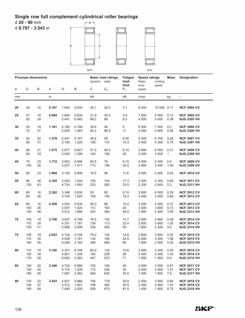
128
Single row full complement cylindrical roller bearingsd 20 - 90 mmd 0.787 - 3.543 in
20 42 16 0.787 1.654 0.630 28.1 28.5 3.1 8 500 10 000 0.11 NCF 3004 CV
25 47 16 0.984 1.850 0.630 31.9 35.5 3.8 7 000 9 000 0.12 NCF 3005 CV62 24 2.441 0.945 68.2 68 8.5 4 500 5 600 0.38 NJG 2305 VH
30 55 19 1.181 2.165 0.748 39.6 44 5 6 000 7 500 0.2 NCF 3006 CV72 27 2.835 1.063 84.2 86.5 11 4 000 4 800 0.56 NJG 2306 VH
35 62 20 1.378 2.441 0.787 48.4 56 6.55 5 300 6 700 0.26 NCF 3007 CV80 31 3.150 1.220 108 114 14.3 3 400 4 300 0.75 NJG 2307 VH
40 68 21 1.575 2.677 0.827 57.2 69.5 8.15 4 800 6 000 0.31 NCF 3008 CV90 33 3.543 1.299 145 156 20 3 000 3 600 1 NJG 2308 VH
45 75 23 1.772 2.953 0.906 60.5 78 9.15 4 300 5 300 0.4 NCF 3009 CV100 36 3.937 1.417 172 196 25.5 2 800 3 400 1.45 NJG 2309 VH
50 80 23 1.969 3.150 0.906 76.5 98 11.8 4 000 5 000 0.43 NCF 3010 CV
55 90 26 2.165 3.543 1.024 105 140 17.3 3 400 4 300 0.64 NCF 3011 CV120 43 4.724 1.693 233 260 33.5 2 200 2 800 2.3 NJG 2311 VH
60 85 16 2.362 3.346 0.630 55 80 9.15 3 600 4 500 0.29 NCF 2912 CV95 26 3.740 1.024 106 146 18.3 3 400 4 000 0.69 NCF 3012 CV
65 90 16 2.559 3.543 0.630 58.3 88 10.2 3 200 4 000 0.31 NCF 2913 CV100 26 3.937 1.024 112 163 20 3 000 3 800 0.73 NCF 3013 CV140 48 5.512 1.890 303 360 46.5 1 900 2 400 3.55 NJG 2313 VH
70 100 19 2.756 3.937 0.748 76.5 116 13.7 3 000 3 800 0.49 NCF 2914 CV110 30 4.331 1.181 128 173 22.4 2 800 3 600 1.02 NCF 3014 CV150 51 5.906 2.008 336 400 50 1 800 2 200 4.4 NJG 2314 VH
75 105 19 2.953 4.134 0.748 79.2 125 14.6 2 800 3 600 0.52 NCF 2915 CV115 30 4.528 1.181 134 190 24.5 2 600 3 200 1.06 NCF 3015 CV160 55 6.299 2.165 396 480 60 1 600 2 000 5.35 NJG 2315 VH
80 110 19 3.150 4.331 0.748 80.9 132 15.6 2 600 3 400 0.55 NCF 2916 CV125 34 4.921 1.339 165 228 29 2 400 3 000 1.43 NCF 3016 CV170 58 6.693 2.283 457 570 71 1 500 1 900 6.4 NJG 2316 VH
85 120 22 3.346 4.724 0.866 102 166 20 2 600 3 200 0.81 NCF 2917 CV130 34 5.118 1.339 172 236 30 2 400 3 000 1.51 NCF 3017 CV180 60 7.087 2.362 484 620 76.5 1 400 1 800 7.4 NJG 2317 VH
90 125 22 3.543 4.921 0.866 106 176 20.8 2 400 3 000 0.84 NCF 2918 CV140 37 5.512 1.457 198 280 35.5 2 200 2 800 1.97 NCF 3018 CV190 64 7.480 2.520 528 670 81.5 1 400 1 800 8.75 NJG 2318 VH
Principal dimensions Basic load ratings Fatigue Speed ratings Mass Designationdynamic static load Refer- Limiting
limit ence speedd D B d D B C C0 Pu speed
mm in kN kN r/min kg –
dD
B
NCF NJG

129
100 140 24 3.937 5.512 0.945 128 200 24.5 2 200 2 600 1.14 NCF 2920 CV150 37 5.906 1.457 209 310 37.5 2 000 2 600 2.15 NCF 3020 CV215 73 8.465 2.874 682 865 104 1 200 1 500 13 NJG 2320 VH
110 150 24 4.331 5.906 0.945 134 220 26 1 900 2 400 1.23 NCF 2922 CV170 45 6.693 1.772 275 400 47.5 1 800 2 200 3.5 NCF 3022 CV240 80 9.449 3.150 858 1 060 122 1 100 1 300 17.5 NJG 2322 VH
120 165 27 4.724 6.496 1.063 172 290 34.5 1 800 2 200 1.73 NCF 2924 CV180 46 7.087 1.811 292 440 52 1 700 2 000 3.8 NCF 3024 CV215 58 8.465 2.283 512 735 85 1 400 1 700 9.05 NCF 2224 V260 86 10.236 3.386 952 1 250 140 1 000 1 200 22.5 NJG 2324 VH
130 180 30 5.118 7.087 1.181 205 360 40.5 1 600 2 000 2.33 NCF 2926 CV200 52 7.874 2.047 413 620 72 1 500 1 900 5.8 NCF 3026 CV280 93 11.024 3.661 1 080 1 430 156 950 1 200 28 NJG 2326 VH
140 190 30 5.512 7.480 1.181 220 390 43 1 500 1 900 2.42 NCF 2928 CV210 53 8.268 2.087 440 680 78 1 400 1 800 6.1 NCF 3028 CV250 68 9.843 2.677 693 1 020 114 1 200 1 500 14.5 NCF 2228 V300 102 11.811 4.016 1 210 1 600 173 850 1 100 35.5 NJG 2328 VH
150 210 36 5.906 8.268 1.417 292 490 55 1 400 1 700 3.77 NCF 2930 CV225 56 8.858 2.205 457 710 80 1 300 1 600 7.5 NCF 3030 CV270 73 10.630 2.874 792 1 180 132 1 100 1 400 18.4 NCF 2230 V320 108 12.598 4.252 1 450 1 930 196 800 1 000 42.5 NJG 2330 VH
160 220 36 6.299 8.661 1.417 303 530 58.5 1 300 1 600 4 NCF 2932 CV240 60 9.449 2.362 512 800 90 1 200 1 500 9.1 NCF 3032 CV290 80 11.417 3.150 990 1 500 160 950 1 200 23 NCF 2232 V
170 230 36 6.693 9.055 1.417 314 560 60 1 200 1 500 4.3 NCF 2934 CV260 67 10.236 2.638 671 1 060 118 1 100 1 400 12.5 NCF 3034 CV310 86 12.205 3.386 1 100 1 700 176 900 1 100 28.7 NCF 2234 V360 120 14.173 4.724 1 760 2 450 236 700 900 59.5 NJG 2334 VH
180 250 42 7.087 9.843 1.654 391 695 75 1 100 1 400 6.2 NCF 2936 CV280 74 11.024 2.913 781 1 250 134 1 100 1 300 16.5 NCF 3036 CV380 126 14.961 4.961 1 870 2 650 255 670 800 69.5 NJG 2336 VH
190 260 42 7.480 10.236 1.654 440 780 81.5 1 100 1 400 6.5 NCF 2938 CV290 75 11.417 2.953 792 1 290 140 1 000 1 300 17 NCF 3038 CV340 92 13.386 3.622 1 250 1 900 196 800 1 000 35.7 NCF 2238 V400 132 15.748 5.197 2 160 3 000 280 630 800 80 NJG 2338 VH
200 250 24 7.874 9.843 0.945 176 335 32.5 1 100 1 400 2.6 NCF 1840 V280 48 11.024 1.890 528 965 100 1 000 1 300 9.1 NCF 2940 CV310 82 12.205 3.228 913 1 530 160 950 1 200 22.5 NCF 3040 CV420 138 16.535 5.433 2 290 3 200 290 600 750 92 NJG 2340 VH
Principal dimensions Basic load ratings Fatigue Speed ratings Mass Designationdynamic static load Refer- Limiting
limit ence speedd D B d D B C C0 Pu speed
mm in kN kN r/min kg –
Single row full complement cylindrical roller bearingsd 100 - 200 mm
d 3.937 - 7.874 in

130
Single row full complement cylindrical roller bearingsd 220 - 420 mmd 8.661 - 16.535 in
220 270 24 8.661 10.630 0.945 183 365 34.5 1 000 1 200 2.85 NCF 1844 V300 48 11.811 1.890 550 1 060 108 950 1 200 9.9 NCF 2944 CV340 90 13.386 3.543 1 080 1 800 186 850 1 100 29.5 NCF 3044 CV400 108 15.748 4.252 1 830 2 750 255 700 850 58 NCF 2244 V460 145 18.110 5.709 2 550 3 550 320 530 670 111 NJG 2344 VH
240 300 28 9.449 11.811 1.102 260 510 47.5 900 1 100 4.4 NCF 1848 V320 48 12.598 1.890 583 1 140 114 850 1 100 10.6 NCF 2948 CV360 92 14.173 3.622 1 140 1 960 200 800 1 000 32 NCF 3048 CV500 155 19.685 6.102 2 810 3 900 345 500 630 147 NJG 2348 VH
260 320 28 10.236 12.598 1.102 270 550 50 800 1 000 4.75 NCF 1852 V360 60 14.173 2.362 748 1 430 143 750 950 18.5 NCF 2952 CV400 104 15.748 4.094 1 540 2 550 250 700 900 46.5 NCF 3052 CV540 165 21.260 6.496 3 410 4 800 415 430 530 177 NJG 2352 VH
280 350 33 11.024 13.780 1.299 341 695 64 750 950 7.1 NCF 1856 V380 60 14.961 2.362 880 1 730 166 700 900 19.7 NCF 2956 CV420 106 16.535 4.173 1 570 2 650 260 670 850 50 NCF 3056 CV
300 380 38 11.811 14.961 1.496 418 850 75 670 850 10 NCF 1860 V420 72 16.535 2.835 1 120 2 200 208 670 800 31.2 NCF 2960 CV460 118 18.110 4.646 1 900 3 250 300 600 750 69 NCF 3060 CV
320 400 38 12.598 15.748 1.496 440 900 80 630 800 10.5 NCF 1864 V440 72 17.323 2.835 1 170 2 360 220 600 750 32.9 NCF 2964 CV480 121 18.898 4.764 1 980 3 450 310 560 700 74.5 NCF 3064 CV
340 420 38 13.386 16.535 1.496 446 950 83 600 750 11 NCF 1868 V460 72 18.110 2.835 1 190 2 500 228 560 700 35 NCF 2968 CV520 133 20.472 5.236 2 380 4 150 355 530 670 100 NCF 3068 CV
360 440 38 14.173 17.323 1.496 402 900 76.5 560 700 11.5 NCF 1872 V480 72 18.898 2.835 1 230 2 600 240 530 670 36.5 NCF 2972 CV540 134 21.260 5.276 2 420 4 300 365 500 630 105 NCF 3072 CV
380 480 46 14.961 18.898 1.811 627 1 290 114 530 670 19.5 NCF 1876 V520 82 20.472 3.228 1 570 3 250 300 500 630 52.5 NCF 2976 CV560 135 22.047 5.315 2 510 4 550 380 480 600 110 NCF 3076 CV
400 500 46 15.748 19.685 1.811 627 1 340 118 500 630 20.5 NCF 1880 V540 82 21.260 3.228 1 650 3 450 310 480 600 54.5 NCF 2980 CV600 148 23.622 5.827 2 970 5 500 450 450 560 145 NCF 3080 CV
420 520 46 16.535 20.472 1.811 660 1 430 122 480 600 21 NCF 1884 V560 82 22.047 3.228 1 650 3 600 315 450 560 57 NCF 2984 CV620 150 24.409 5.906 3 030 5 700 455 430 530 150 NCF 3084 CV
Principal dimensions Basic load ratings Fatigue Speed ratings Mass Designationdynamic static load Refer- Limiting
limit ence speedd D B d D B C C0 Pu speed
mm in kN kN r/min kg –
dD
B
NCF NJG

131
440 540 46 17.323 21.260 1.811 671 1 460 125 450 560 22 NCF 1888 V540 60 21.260 2.362 968 2 360 204 450 560 29 NCF 2888 V600 95 23.622 3.740 2 010 4 400 380 430 530 80.5 NCF 2988 V650 157 25.591 6.181 3 580 6 550 520 400 500 175 NCF 3088 CV
460 580 56 18.110 22.835 2.205 913 1 960 163 430 530 34 NCF 1892 V580 72 22.835 2.835 1 300 3 050 260 430 530 44 NCF 2892 V620 95 24.409 3.740 2 050 4 500 390 400 500 83.5 NCF 2992 V680 163 26.772 6.417 3 690 6 950 540 380 480 195 NCF 3092 CV
480 600 56 18.898 23.622 2.205 935 2 040 170 400 500 35.5 NCF 1896 V600 72 23.622 2.835 1 320 3 150 265 400 500 46 NCF 2896 V650 100 25.591 3.937 2 290 4 900 405 380 480 98 NCF 2996 V700 165 27.559 6.496 3 740 7 200 550 360 450 205 NCF 3096 CV
500 620 56 19.685 24.409 2.205 952 2 120 173 380 480 36.5 NCF 18/500 V620 72 24.409 2.835 1 340 3 350 275 380 480 48 NCF 28/500 V670 100 26.378 3.937 2 330 5 000 415 380 450 100 NCF 29/500 V720 167 28.346 6.575 3 800 7 500 570 360 450 215 NCF 30/500 CV
530 650 56 20.866 25.591 2.205 990 2 240 180 360 450 38.5 NCF 18/530 V650 72 25.591 2.835 1 400 3 450 285 360 450 49.5 NCF 28/530 V710 106 27.953 4.173 2 640 6 100 480 340 430 120 NCF 29/530 V780 185 30.709 7.283 5 230 10 600 780 320 400 300 NCF 30/530 V
560 680 56 22.047 26.772 2.205 1 020 2 360 186 340 430 40.5 NCF 18/560 V680 72 26.772 2.835 1 420 3 650 300 340 430 54 NCF 28/560 V750 112 29.528 4.409 3 080 6 700 500 320 400 140 NCF 29/560 V820 195 32.283 7.677 5 830 11 800 865 300 380 345 NCF 30/560 V
600 730 60 23.622 28.740 2.362 1 050 2 550 196 320 400 51.5 NCF 18/600 V730 78 28.740 3.071 1 570 4 300 340 320 400 67.5 NCF 28/600 V800 118 31.496 4.646 3 190 7 100 520 300 380 170 NCF 29/600 V
630 780 69 24.803 30.709 2.717 1 250 2 900 232 300 360 72.5 NCF 18/630 V780 88 30.709 3.465 1 870 5 000 390 300 360 92.5 NCF 28/630 V850 128 33.465 5.039 3 740 8 650 610 280 340 205 NCF 29/630 V
670 820 69 26.378 32.283 2.717 1 300 3 150 245 280 340 76.5 NCF 18/670 V820 88 32.283 3.465 1 940 5 300 415 280 340 97.5 NCF 28/670 V900 136 35.433 5.354 3 910 9 000 630 260 320 245 NCF 29/670 V
710 870 74 27.953 34.252 2.913 1 540 3 750 285 260 320 92.5 NCF 18/710 V870 95 34.252 3.740 2 330 6 300 480 260 320 115 NCF 28/710 V950 140 37.402 5.512 4 290 10 000 695 240 300 275 NCF 29/710 V
750 920 78 29.528 36.220 3.071 1 870 4 500 335 240 300 110 NCF 18/750 V920 100 36.220 3.937 2 640 6 950 520 240 300 140 NCF 28/750 V1 000 145 39.370 5.709 4 460 10 600 710 220 280 315 NCF 29/750 V
Principal dimensions Basic load ratings Fatigue Speed ratings Mass Designationdynamic static load Refer- Limiting
limit ence speedd D B d D B C C0 Pu speed
mm in kN kN r/min kg –
Single row full complement cylindrical roller bearingsd 440 - 750 mm
d 17.323 - 29.528 in

132
Single row full complement cylindrical roller bearingsd 800 - 1 120 mmd 31.496 - 44.094 in
800 980 82 31.496 38.583 3.228 1 940 4 800 345 220 280 130 NCF 18/800 V980 106 38.583 4.173 2 750 7 500 550 220 280 165 NCF 28/800 V1 060 150 41.732 5.906 4 950 12 200 800 200 260 360 NCF 29/800 V
850 1 030 82 33.465 40.551 3.228 2 010 5 100 365 200 260 135 NCF 18/850 V1 030 106 40.551 4.173 2 860 8 000 570 200 260 175 NCF 28/850 V1 120 155 44.094 6.102 5 230 12 700 830 190 240 405 NCF 29/850 V
900 1 090 85 35.433 42.913 3.346 2 380 6 000 425 190 240 160 NCF 18/900 V1 090 112 42.913 4.409 3 190 9 150 655 190 240 208 NCF 28/900 V1 180 165 46.457 6.496 5 940 14 600 950 170 220 472 NCF 29/900 V
950 1 150 90 37.402 45.276 3.543 2 420 6 300 440 170 220 185 NCF 18/950 V1 150 118 45.276 4.646 3 410 9 800 655 170 220 240 NCF 28/950 V1 250 175 49.213 6.890 6 600 16 300 1 020 160 200 565 NCF 29/950 V
1 000 1 220 100 39.370 48.031 3.937 2 920 7 500 455 160 200 230 NCF 18/1000 V1 320 185 51.968 7.283 7 480 18 600 1 160 150 190 680 NCF 29/1000 V
1 120 1 360 106 44.094 53.543 4.173 3 740 9 650 585 130 170 298 NCF 18/1120 V
Principal dimensions Basic load ratings Fatigue Speed ratings Mass Designationdynamic static load Refer- Limiting
limit ence speedd D B d D B C C0 Pu speed
mm in kN kN r/min kg –
dD
B
NCF NJG

133
20 42 30 0.787 1.654 1.181 52.3 57 6.2 8 500 10 000 0.2 NNCF 5004 CV
25 47 30 0.984 1.850 1.181 59.4 71 7.65 7 000 9 000 0.23 NNCF 5005 CV
30 55 34 1.181 2.165 1.339 73.7 88 10 6 000 7 500 0.35 NNCF 5006 CV
35 62 36 1.378 2.441 1.417 89.7 112 12.9 5 300 6 700 0.46 NNCF 5007 CV
40 68 38 1.575 2.677 1.496 106 140 16.3 4 800 6 000 0.56 NNCF 5008 CV
45 75 40 1.772 2.953 1.575 112 156 18.3 4 300 5 300 0.71 NNCF 5009 CV
50 80 40 1.969 3.150 1.575 142 196 23.6 4 000 5 000 0.76 NNCF 5010 CV
55 90 46 2.165 3.543 1.811 190 280 34.5 3 400 4 300 1.16 NNCF 5011 CV
60 85 25 2.362 3.346 0.984 78.1 137 14.3 3 600 4 500 0.49 NNCF 4912 CV85 25 3.346 0.984 78.1 137 14.3 3 600 4 500 0.49 NNC 4912 CV85 25 3.346 0.984 78.1 137 14.3 3 600 4 500 0.49 NNCL 4912 CV95 46 3.740 1.811 198 300 36.5 3 400 4 000 1.24 NNCF 5012 CV
65 100 46 2.559 3.937 1.811 209 325 40 3 000 3 800 1.32 NNCF 5013 CV
70 100 30 2.756 3.937 1.181 114 193 22.4 3 000 3 800 0.78 NNCF 4914 CV100 30 3.937 1.181 114 193 22.4 3 000 3 800 0.78 NNC 4914 CV100 30 3.937 1.181 114 193 22.4 3 000 3 800 0.78 NNCL 4914 CV110 54 4.331 2.126 238 345 45 2 800 3 600 1.85 NNCF 5014 CV
75 115 54 2.953 4.528 2.126 251 380 49 2 600 3 200 1.93 NNCF 5015 CV
80 110 30 3.150 4.331 1.181 121 216 25 2 600 3 400 0.88 NNCF 4916 CV110 30 4.331 1.181 121 216 25 2 800 3 400 0.88 NNC 4916 CV110 30 4.331 1.181 121 216 25 2 600 3 400 0.88 NNCL 4916 CV125 60 4.921 2.362 308 455 58.5 2 400 3 000 2.59 NNCF 5016 CV
85 130 60 3.346 5.118 2.362 314 475 60 2 400 3 000 2.72 NNCF 5017 CV
90 125 35 3.543 4.921 1.378 161 300 35.5 2 400 3 000 1.35 NNCF 4918 CV125 35 4.921 1.378 161 300 35.5 2 400 3 000 1.35 NNC 4918 CV125 35 4.921 1.378 161 300 35.5 2 400 3 000 1.35 NNCL 4918 CV140 67 5.512 2.638 369 560 69.5 2 200 2 800 3.62 NNCF 5018 CV
100 140 40 3.937 5.512 1.575 209 400 46.5 2 000 2 600 2 NNCF 4920 CV140 40 5.512 1.575 209 400 46.5 2 000 2 600 1.95 NNC 4920 CV140 40 5.512 1.575 209 400 46.5 2 000 2 600 1.95 NNCL 4920 CV150 67 5.906 2.638 391 620 75 2 000 2 600 3.94 NNCF 5020 CV
Principal dimensions Basic load ratings Fatigue Speed ratings Mass Designationdynamic static load Refer- Limiting
limit ence speedd D B d D B C C0 Pu speed
mm in kN kN r/min kg –
Double row full complement cylindrical roller bearingsd 20 - 100 mm
d 0.787 - 3.937 in
dD
B
NNCL NNCF NNC

134
Double row full complement cylindrical roller bearingsd 110 - 170 mmd 4.331 - 6.693 in
110 150 40 4.331 5.906 1.575 220 430 49 1 900 2 400 2.15 NNCF 4922 CV150 40 5.906 1.575 220 430 49 1 900 2 400 2.15 NNC 4922 CV150 40 5.906 1.575 220 430 49 1 900 2 400 2.15 NNCL 4922 CV170 80 6.693 3.150 512 800 95 1 800 2 200 6.32 NNCF 5022 CV
120 165 45 4.724 6.496 1.772 242 480 53 1 700 2 200 2.95 NNCF 4924 CV165 45 6.496 1.772 242 480 53 1 700 2 200 2.95 NNC 4924 CV165 45 6.496 1.772 242 480 53 1 700 2 200 2.95 NNCL 4924 CV180 80 7.087 3.150 539 880 104 1 700 2 000 6.77 NNCF 5024 CV
130 180 50 5.118 7.087 1.969 275 530 60 1 600 2 000 3.95 NNCF 4926 CV180 50 7.087 1.969 275 530 60 1 600 2 000 3.95 NNC 4926 CV180 50 7.087 1.969 275 530 60 1 600 2 000 3.95 NNCL 4926 CV200 95 7.874 3.740 765 1 250 143 1 500 1 900 10.2 NNCF 5026 CV
140 190 50 5.512 7.480 1.969 286 570 63 1 500 1 900 4.2 NNCF 4928 CV190 50 7.480 1.969 286 570 63 1 500 1 900 4.2 NNC 4928 CV190 50 7.480 1.969 286 570 63 1 500 1 900 4.2 NNCL 4928 CV210 95 8.268 3.740 809 1 370 156 1 400 1 800 11.1 NNCF 5028 CV
150 190 40 5.906 7.480 1.575 255 585 60 1 500 1 800 2.7 NNCF 4830 CV190 40 7.480 1.575 255 585 60 1 500 1 800 2.9 NNC 4830 CV190 40 7.480 1.575 255 585 60 1 500 1 800 2.7 NNCL 4830 CV
210 60 8.268 2.362 429 830 91.5 1 400 1 700 6.65 NNCF 4930 CV210 60 8.268 2.362 429 830 91.5 1 400 1 700 6.65 NNC 4930 CV210 60 8.268 2.362 429 830 91.5 1 400 1 700 6.65 NNCL 4930 CV225 100 8.858 3.937 842 1 430 160 1 300 1 700 13.3 NNCF 5030 CV
160 200 40 6.299 7.874 1.575 260 610 62 1 400 1 700 2.9 NNCF 4832 CV200 40 7.874 1.575 260 610 62 1 400 1 700 3.1 NNC 4832 CV200 40 7.874 1.575 260 610 62 1 400 1 700 2.9 NNCL 4832 CV
220 60 8.661 2.362 446 915 96.5 1 300 1 600 7 NNCF 4932 CV220 60 8.661 2.362 446 915 96.5 1 300 1 600 7 NNC 4932 CV220 60 8.661 2.362 446 915 96.5 1 300 1 600 7 NNCL 4932 CV240 109 9.449 4.291 952 1 600 180 1 200 1 500 16.2 NNCF 5032 CV
170 215 45 6.693 8.465 1.772 286 655 65.5 1 300 1 600 3.9 NNCF 4834 CV215 45 8.465 1.772 286 655 65.5 1 300 1 600 4.1 NNC 4834 CV215 45 8.465 1.772 286 655 65.5 1 300 1 600 3.9 NNCL 4834 CV
230 60 9.055 2.362 457 950 100 1 200 1 500 7.35 NNCF 4934 CV230 60 9.055 2.362 457 950 100 1 200 1 500 7.35 NNC 4934 CV230 60 9.055 2.362 457 950 100 1 200 1 500 7.35 NNCL 4934 CV260 122 10.236 4.803 1 230 2 120 236 1 100 1 400 23 NNCF 5034 CV
Principal dimensions Basic load ratings Fatigue Speed ratings Mass Designationdynamic static load Refer- Limiting
limit ence speedd D B d D B C C0 Pu speed
mm in kN kN r/min kg –
dD
B
NNCL NNCF NNC

135
180 225 45 7.087 8.858 1.772 297 695 69.5 1 200 1 500 4 NNCF 4836 CV225 45 8.858 1.772 297 695 69.5 1 200 1 500 4.3 NNC 4836 CV225 45 8.858 1.772 297 695 69.5 1 200 1 500 4 NNCL 4836 CV
250 69 9.843 2.717 594 1 220 127 1 100 1 400 10.8 NNCF 4936 CV250 69 9.843 2.717 594 1 220 127 1 100 1 400 10.8 NNC 4936 CV250 69 9.843 2.717 594 1 220 127 1 100 1 400 10.8 NNCL 4936 CV280 136 11.024 5.354 1 420 2 500 270 1 100 1 300 30.5 NNCF 5036 CV
190 240 50 7.480 9.449 1.969 330 750 76.5 1 100 1 400 5.3 NNCF 4838 CV240 50 9.449 1.969 330 750 76.5 1 100 1 400 5.65 NNC 4838 CV240 50 9.449 1.969 330 750 76.5 1 100 1 400 5.3 NNCL 4838 CV
260 69 10.236 2.717 605 1 290 132 1 100 1 400 11.2 NNCF 4938 CV260 69 10.236 2.717 605 1 290 132 1 100 1 400 11.2 NNC 4938 CV260 69 10.236 2.717 605 1 290 132 1 100 1 400 11.2 NNCL 4938 CV290 136 11.417 5.354 1 470 2 600 280 1 000 1 300 31.5 NNCF 5038 CV
200 250 50 7.874 9.843 1.969 336 800 80 1 100 1 400 5.5 NNCF 4840 CV250 50 9.843 1.969 336 800 80 1 100 1 400 5.9 NNC 4840 CV250 50 9.843 1.969 336 800 80 1 100 1 400 5.5 NNCL 4840 CV
280 80 11.024 3.150 704 1 500 153 1 000 1 300 15.8 NNCF 4940 CV280 80 11.024 3.150 704 1 500 153 1 000 1 300 15.8 NNC 4940 CV280 80 11.024 3.150 704 1 500 153 1 000 1 300 15.8 NNCL 4940 CV310 150 12.205 5.906 1 680 3 050 320 950 1 200 41 NNCF 5040 CV
220 270 50 8.661 10.630 1.969 352 865 85 1 000 1 200 5.9 NNCF 4844 CV270 50 10.630 1.969 352 865 85 1 000 1 200 6.4 NNC 4844 CV270 50 10.630 1.969 352 865 85 1 000 1 200 5.9 NNCL 4844 CV
300 80 11.811 3.150 737 1 600 160 950 1 200 17.2 NNCF 4944 CV300 80 11.811 3.150 737 1 600 160 950 1 200 17.2 NNC 4944 CV300 80 11.811 3.150 737 1 600 160 950 1 200 17.2 NNCL 4944 CV340 160 13.386 6.299 2 010 3 600 375 850 1 100 52.5 NNCF 5044 CV
240 300 60 9.449 11.811 2.362 539 1 290 125 900 1 100 9.1 NNCF 4848 CV300 60 11.811 2.362 539 1 290 125 900 1 100 10 NNC 4848 CV300 60 11.811 2.362 539 1 290 125 900 1 100 9.1 NNCL 4848 CV
320 80 12.598 3.150 781 1 760 173 850 1 100 18.5 NNCF 4948 CV320 80 12.598 3.150 781 1 760 173 850 1 100 18.5 NNC 4948 CV320 80 12.598 3.150 781 1 760 173 850 1 100 18.5 NNCL 4948 CV360 160 14.173 6.299 2 120 3 900 400 800 1 000 56 NNCF 5048 CV
Principal dimensions Basic load ratings Fatigue Speed ratings Mass Designationdynamic static load Refer- Limiting
limit ence speedd D B d D B C C0 Pu speed
mm in kN kN r/min kg –
Double row full complement cylindrical roller bearingsd 180 - 240 mm
d 7.087 - 9.449 in

136
Double row full complement cylindrical roller bearingsd 260 - 340 mmd 10.236 - 13.386 in
260 320 60 10.236 12.598 2.362 561 1 400 132 800 1 000 9.7 NNCF 4852 CV320 60 12.598 2.362 561 1 400 132 800 1 000 11 NNC 4852 CV320 60 12.598 2.362 561 1 400 132 800 1 000 9.7 NNCL 4852 CV
360 100 14.173 3.937 1 170 2 550 245 750 950 32 NNCF 4952 CV360 100 14.173 3.937 1 170 2 550 245 750 950 32 NNC 4952 CV360 100 14.173 3.937 1 170 2 550 245 750 950 32 NNCL 4952 CV400 190 15.748 7.480 2 860 5 200 520 700 900 85.5 NNCF 5052 CV
280 350 69 11.024 13.780 2.717 737 1 860 173 750 950 15.3 NNCF 4856 CV350 69 13.780 2.717 737 1 860 173 750 950 16 NNC 4856 CV350 69 13.780 2.717 737 1 860 173 750 950 15.3 NNCL 4856 CV
380 100 14.961 3.937 1 210 2 700 255 700 900 34 NNCF 4956 CV380 100 14.961 3.937 1 210 2 700 255 700 900 34 NNC 4956 CV380 100 14.961 3.937 1 210 2 700 255 700 900 34 NNCL 4956 CV420 190 16.535 7.480 2 920 5 600 540 670 850 90.5 NNCF 5056 CV
300 380 80 11.811 14.961 3.150 858 2 120 196 700 850 21.8 NNCF 4860 CV380 80 14.961 3.150 858 2 120 196 700 850 23 NNC 4860 CV380 80 14.961 3.150 858 2 120 196 700 850 21.8 NNCL 4860 CV
420 118 16.535 4.646 1 680 3 750 355 670 800 53 NNCF 4960 CV420 118 16.535 4.646 1 680 3 750 355 670 800 53 NNC 4960 CV420 118 16.535 4.646 1 680 3 750 355 670 800 53 NNCL 4960 CV460 218 18.110 8.583 3 250 6 550 600 600 750 130 NNCF 5060 CV
320 400 80 12.598 15.748 3.150 897 2 280 208 630 800 22.7 NNCF 4864 CV400 80 15.748 3.150 897 2 280 208 630 800 24 NNC 4864 CV400 80 15.748 3.150 897 2 280 208 630 800 22.7 NNCL 4864 CV
440 118 17.323 4.646 1 760 4 050 375 600 750 56 NNCF 4964 CV440 118 17.323 4.646 1 760 4 050 375 600 750 56 NNC 4964 CV440 118 17.323 4.646 1 760 4 050 375 600 750 56 NNCL 4964 CV480 218 18.898 8.583 3 690 6 950 620 560 700 135 NNCF 5064 CV
340 420 80 13.386 16.535 3.150 913 2 400 216 600 750 25.5 NNCF 4868 CV420 80 16.535 3.150 913 2 400 216 600 750 25.5 NNC 4868 CV420 80 16.535 3.150 913 2 400 216 600 750 25.5 NNCL 4868 CV
460 118 18.110 4.646 1 790 4 250 390 560 700 59 NNCF 4968 CV460 118 18.110 4.646 1 790 4 250 390 560 700 59 NNC 4968 CV460 118 18.110 4.646 1 790 4 250 390 560 700 59 NNCL 4968 CV520 243 20.472 9.567 4 400 8 300 710 530 670 185 NNCF 5068 CV
Principal dimensions Basic load ratings Fatigue Speed ratings Mass Designationdynamic static load Refer- Limiting
limit ence speedd D B d D B C C0 Pu speed
mm in kN kN r/min kg –
dD
B
NNCL NNCF NNC

137
360 440 80 14.173 17.323 3.150 935 2 550 224 560 700 27 NNCF 4872 CV440 80 17.323 3.150 935 2 550 224 560 700 27 NNC 4872 CV440 80 17.323 3.150 935 2 550 224 560 700 27 NNCL 4872 CV
480 118 18.898 4.646 1 830 4 500 405 530 670 62.1 NNCF 4972 CV480 118 18.898 4.646 1 830 4 500 405 530 670 62.1 NNC 4972 CV480 118 18.898 4.646 1 830 4 500 405 530 670 60.8 NNCL 4972 CV540 243 21.260 9.567 4 460 8 650 735 500 630 195 NNCF 5072 CV
380 480 100 14.961 18.898 3.937 1 400 3 650 315 530 670 45.5 NNCF 4876 CV480 100 18.898 3.937 1 400 3 650 315 530 670 45.5 NNC 4876 CV480 100 18.898 3.937 1 400 3 650 315 530 670 45.5 NNCL 4876 CV
520 140 20.472 5.512 2 380 5 700 500 500 630 92.4 NNCF 4976 CV520 140 20.472 5.512 2 380 5 700 500 500 630 92.4 NNC 4976 CV520 140 20.472 5.512 2 380 5 700 500 500 630 92.4 NNCL 4976 CV560 243 22.047 9.567 4 680 9 150 735 480 600 200 NNCF 5076 CV
400 500 100 15.748 19.685 3.937 1 420 3 750 325 500 630 46.5 NNCF 4880 CV500 100 19.685 3.937 1 420 3 750 325 500 630 46.5 NNC 4880 CV500 100 19.685 3.937 1 420 3 750 325 500 630 46.5 NNCL 4880 CV
540 140 21.260 5.512 2 420 6 000 520 480 600 96.5 NNCF 4980 CV540 140 21.260 5.512 2 420 6 000 520 480 600 96.5 NNC 4980 CV540 140 21.260 5.512 2 420 6 000 520 480 600 96.5 NNCL 4980 CV600 272 23.622 10.709 5 500 11 000 900 450 560 270 NNCF 5080 CV
Principal dimensions Basic load ratings Fatigue Speed ratings Mass Designationdynamic static load Refer- Limiting
limit ence speedd D B d D B C C0 Pu speed
mm in kN kN r/min kg –
Double row full complement cylindrical roller bearingsd 360 - 400 mm
d 14.173 - 15.748 in

138
Sealed double row full complement cylindrical roller bearingsd 20 - 160 mmd 0.787 - 6.299 in
20 42 30 29 0.787 1.654 1.181 1.142 44 52 5.4 3 600 0.21 NNF 5004 ADA-2LSV
25 47 30 29 0.984 1.850 1.181 1.142 48.4 62 6.4 3 000 0.23 NNF 5005 ADA-2LSV
30 55 34 33 1.181 2.165 1.339 1.299 57.2 75 7.8 2 600 0.35 NNF 5006 ADA-2LSV
35 62 36 35 1.378 2.441 1.417 1.378 70.4 91.5 10.2 2 200 0.45 NNF 5007 ADA-2LSV
40 68 38 37 1.575 2.677 1.496 1.457 85.8 116 13.4 2 000 0.53 NNF 5008 ADA-2LSV
45 75 40 39 1.772 2.953 1.575 1.535 102 146 17 1 800 0.68 NNF 5009 ADA-2LSV
50 80 40 39 1.969 3.150 1.575 1.535 108 160 18.6 1 700 0.73 NNF 5010 ADA-2LSV
55 90 46 45 2.165 3.543 1.811 1.772 128 193 22.8 1 500 1.1 NNF 5011 ADA-2LSV
60 95 46 45 2.362 3.740 1.811 1.772 134 208 25 1 400 1.2 NNF 5012 ADA-2LSV
65 100 46 45 2.559 3.937 1.811 1.772 138 224 26.5 1 300 1.3 NNF 5013 ADA-2LSV
70 110 54 53 2.756 4.331 2.126 2.087 205 325 40.5 1 200 1.85 NNF 5014 ADA-2LSV
75 115 54 53 2.953 4.528 2.126 2.087 216 355 44 1 100 2 NNF 5015 ADA-2LSV
80 125 60 59 3.150 4.921 2.362 2.323 251 415 53 1 000 2.7 NNF 5016 ADA-2LSV
85 130 60 59 3.346 5.118 2.362 2.323 270 430 55 1 000 2.75 NNF 5017 ADA-2LSV
90 140 67 66 3.543 5.512 2.638 2.598 319 550 69.5 900 3.8 NNF 5018 ADA-2LSV
95 145 67 66 3.740 5.709 2.638 2.598 330 570 71 900 3.95 NNF 5019 ADA-2LSV
100 150 67 66 3.937 5.906 2.638 2.598 336 570 68 850 4.05 NNF 5020 ADA-2LSV
110 170 80 79 4.331 6.693 3.150 3.110 413 695 81.5 750 6.45 NNF 5022 ADA-2LSV
120 180 80 79 4.724 7.087 3.150 3.110 429 750 86.5 700 6.9 NNF 5024 ADA-2LSV
130 190 80 79 5.118 7.480 3.150 3.110 446 815 91.5 670 7.5 319426 DA-2LS200 95 94 7.874 3.740 3.701 616 1 040 120 630 10.5 NNF 5026 ADA-2LSV
140 200 80 79 5.512 7.874 3.150 3.110 468 865 96.5 630 8 319428 DA-2LS210 95 94 8.268 3.740 3.701 644 1 120 127 600 11 NNF 5028 ADA-2LSV
150 210 80 79 5.906 8.268 3.150 3.110 468 900 96.5 560 8.4 319430 DA-2LS225 100 99 8.858 3.937 3.898 748 1 290 143 560 13.5 NNF 5030 ADA-2LSV
160 220 80 79 6.299 8.661 3.150 3.110 501 1 000 106 530 8.8 319432 DA-2LS240 109 108 9.449 4.291 4.252 781 1 400 153 500 16.5 NNF 5032 ADA-2LSV
Principal dimensions Basic load ratings Fatigue Limiting Mass Designationdynamic static load speed
limitd D B C d D B C C C0 Pu
mm in kN kN r/min kg –
D
C
d
B
30°

139
170 230 80 79 6.693 9.055 3.150 3.110 512 1 060 110 530 9.3 319434 DA-2LS260 122 121 10.236 4.803 4.764 1 010 1 800 193 480 22.5 NNF 5034 ADA-2LSV
180 240 80 79 7.087 9.449 3.150 3.110 528 1 100 114 500 9.8 319436 DA-2LS280 136 135 11.024 5.354 5.315 1 170 2 120 228 450 30 NNF 5036 ADA-2LSV
190 260 80 79 7.480 10.236 3.150 3.110 550 1 180 120 450 12.7 319438 DA-2LS290 136 135 11.417 5.354 5.315 1 190 2 200 236 430 31.5 NNF 5038 ADA-2LSV
200 270 80 79 7.874 10.630 3.150 3.110 561 1 250 125 430 13.2 319440 DA-2LS310 150 149 12.205 5.906 5.866 1 450 2 900 300 400 42 NNF 5040 ADA-2LSV
220 340 160 159 8.661 13.386 6.299 6.260 1 610 3 100 315 360 53.5 NNF 5044 ADA-2LSV
240 360 160 159 9.449 14.173 6.299 6.260 1 680 3 350 335 340 57.5 NNF 5048 ADA-2LSV
Principal dimensions Basic load ratings Fatigue Limiting Mass Designationdynamic static load speed
limitd D B C d D B C C C0 Pu
mm in kN kN r/min kg –
Sealed double row full complement cylindrical roller bearingsd 170 - 240 mm
d 6.693 - 9.449 in
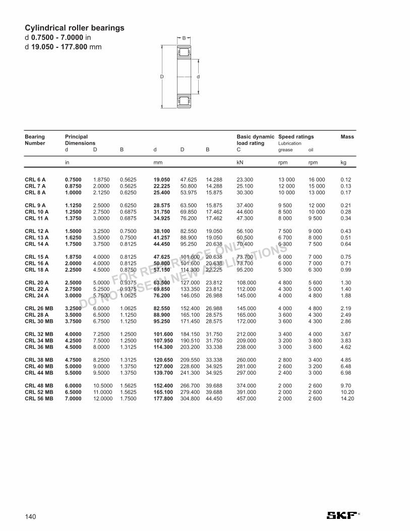
FOR REFERENCE ONLY
DO NOT USE IN NEW APPLICATIONS
CRL 6 A 0.7500 1.8750 0.5625 19.050 47.625 14.288 23.300 13 000 16 000 0.12CRL 7 A 0.8750 2.0000 0.5625 22.225 50.800 14.288 25.100 12 000 15 000 0.13CRL 8 A 1.0000 2.1250 0.6250 25.400 53.975 15.875 30.300 10 000 13 000 0.17
CRL 9 A 1.1250 2.5000 0.6250 28.575 63.500 15.875 37.400 9 500 12 000 0.21CRL 10 A 1.2500 2.7500 0.6875 31.750 69.850 17.462 44.600 8 500 10 000 0.28CRL 11 A 1.3750 3.0000 0.6875 34.925 76.200 17.462 47.300 8 000 9 500 0.34
CRL 12 A 1.5000 3.2500 0.7500 38.100 82.550 19.050 56.100 7 500 9 000 0.43CRL 13 A 1.6250 3.5000 0.7500 41.257 88.900 19.050 60.500 6 700 8 000 0.51CRL 14 A 1.7500 3.7500 0.8125 44.450 95.250 20.638 70.400 6 300 7 500 0.64
CRL 15 A 1.8750 4.0000 0.8125 47.625 101.600 20.638 73.700 6 000 7 000 0.75CRL 16 A 2.0000 4.0000 0.8125 50.800 101.600 20.638 73.700 6 000 7 000 0.71CRL 18 A 2.2500 4.5000 0.8750 57.150 114.300 22.225 95.200 5 300 6 300 0.99
CRL 20 A 2.5000 5.0000 0.9375 63.500 127.000 23.812 108.000 4 800 5 600 1.30CRL 22 A 2.7500 5.2500 0.9375 69.850 133.350 23.812 112.000 4 300 5 000 1.40CRL 24 A 3.0000 5.7500 1.0625 76.200 146.050 26.988 145.000 4 000 4 800 1.88
CRL 26 MB 3.2500 6.0000 1.0625 82.550 152.400 26.988 145.000 4 000 4 800 2.19CRL 28 A 3.5000 6.5000 1.1250 88.900 165.100 28.575 165.000 3 600 4 300 2.49CRL 30 MB 3.7500 6.7500 1.1250 95.250 171.450 28.575 172.000 3 600 4 300 2.86
CRL 32 MB 4.0000 7.2500 1.2500 101.600 184.150 31.750 212.000 3 400 4 000 3.67CRL 34 MB 4.2500 7.5000 1.2500 107.950 190.510 31.750 209.000 3 200 3 800 3.83CRL 36 MB 4.5000 8.0000 1.3125 114.300 203.200 33.338 238.000 3 000 3 600 4.62
CRL 38 MB 4.7500 8.2500 1.3125 120.650 209.550 33.338 260.000 2 800 3 400 4.85CRL 40 MB 5.0000 9.0000 1.3750 127.000 228.600 34.925 281.000 2 600 3 200 6.48CRL 44 MB 5.5000 9.5000 1.3750 139.700 241.300 34.925 297.000 2 400 3 000 6.98
CRL 48 MB 6.0000 10.5000 1.5625 152.400 266.700 39.688 374.000 2 000 2 600 9.70CRL 52 MB 6.5000 11.0000 1.5625 165.100 279.400 39.688 391.000 2 000 2 600 10.20CRL 56 MB 7.0000 12.0000 1.7500 177.800 304.800 44.450 457.000 2 000 2 600 14.20
140
Cylindrical roller bearingsd 0.7500 - 7.0000 ind 19.050 - 177.800 mm
Bearing Principal Basic dynamic Speed ratings MassNumber Dimensions load rating Lubrication
d D B d D B C grease oil
in mm kN rpm rpm kg
D
B
d
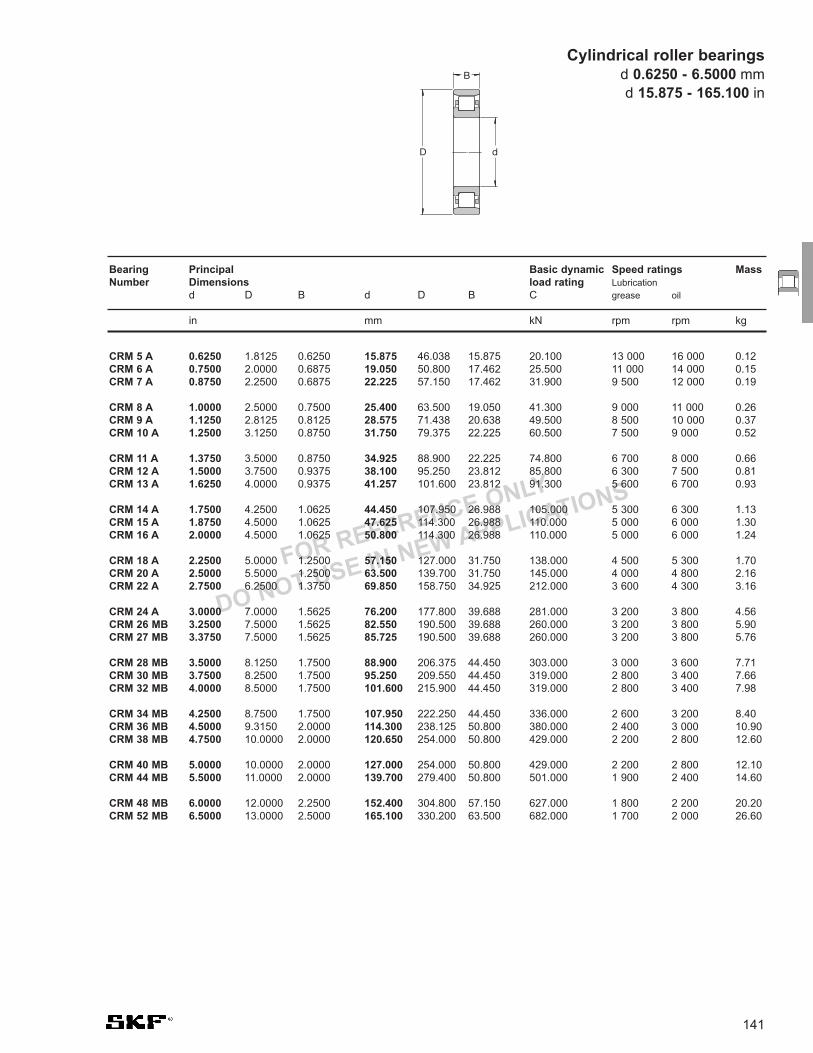
FOR REFERENCE ONLY
DO NOT USE IN NEW APPLICATIONS
141
CRM 5 A 0.6250 1.8125 0.6250 15.875 46.038 15.875 20.100 13 000 16 000 0.12CRM 6 A 0.7500 2.0000 0.6875 19.050 50.800 17.462 25.500 11 000 14 000 0.15CRM 7 A 0.8750 2.2500 0.6875 22.225 57.150 17.462 31.900 9 500 12 000 0.19
CRM 8 A 1.0000 2.5000 0.7500 25.400 63.500 19.050 41.300 9 000 11 000 0.26CRM 9 A 1.1250 2.8125 0.8125 28.575 71.438 20.638 49.500 8 500 10 000 0.37CRM 10 A 1.2500 3.1250 0.8750 31.750 79.375 22.225 60.500 7 500 9 000 0.52
CRM 11 A 1.3750 3.5000 0.8750 34.925 88.900 22.225 74.800 6 700 8 000 0.66CRM 12 A 1.5000 3.7500 0.9375 38.100 95.250 23.812 85.800 6 300 7 500 0.81CRM 13 A 1.6250 4.0000 0.9375 41.257 101.600 23.812 91.300 5 600 6 700 0.93
CRM 14 A 1.7500 4.2500 1.0625 44.450 107.950 26.988 105.000 5 300 6 300 1.13CRM 15 A 1.8750 4.5000 1.0625 47.625 114.300 26.988 110.000 5 000 6 000 1.30CRM 16 A 2.0000 4.5000 1.0625 50.800 114.300 26.988 110.000 5 000 6 000 1.24
CRM 18 A 2.2500 5.0000 1.2500 57.150 127.000 31.750 138.000 4 500 5 300 1.70CRM 20 A 2.5000 5.5000 1.2500 63.500 139.700 31.750 145.000 4 000 4 800 2.16CRM 22 A 2.7500 6.2500 1.3750 69.850 158.750 34.925 212.000 3 600 4 300 3.16
CRM 24 A 3.0000 7.0000 1.5625 76.200 177.800 39.688 281.000 3 200 3 800 4.56CRM 26 MB 3.2500 7.5000 1.5625 82.550 190.500 39.688 260.000 3 200 3 800 5.90CRM 27 MB 3.3750 7.5000 1.5625 85.725 190.500 39.688 260.000 3 200 3 800 5.76
CRM 28 MB 3.5000 8.1250 1.7500 88.900 206.375 44.450 303.000 3 000 3 600 7.71CRM 30 MB 3.7500 8.2500 1.7500 95.250 209.550 44.450 319.000 2 800 3 400 7.66CRM 32 MB 4.0000 8.5000 1.7500 101.600 215.900 44.450 319.000 2 800 3 400 7.98
CRM 34 MB 4.2500 8.7500 1.7500 107.950 222.250 44.450 336.000 2 600 3 200 8.40CRM 36 MB 4.5000 9.3150 2.0000 114.300 238.125 50.800 380.000 2 400 3 000 10.90CRM 38 MB 4.7500 10.0000 2.0000 120.650 254.000 50.800 429.000 2 200 2 800 12.60
CRM 40 MB 5.0000 10.0000 2.0000 127.000 254.000 50.800 429.000 2 200 2 800 12.10CRM 44 MB 5.5000 11.0000 2.0000 139.700 279.400 50.800 501.000 1 900 2 400 14.60
CRM 48 MB 6.0000 12.0000 2.2500 152.400 304.800 57.150 627.000 1 800 2 200 20.20CRM 52 MB 6.5000 13.0000 2.5000 165.100 330.200 63.500 682.000 1 700 2 000 26.60
Bearing Principal Basic dynamic Speed ratings MassNumber Dimensions load rating Lubrication
d D B d D B C grease oil
in mm kN rpm rpm kg
Cylindrical roller bearingsd 0.6250 - 6.5000 mmd 15.875 - 165.100 in
D
B
d

142

143
32302 B J2 / Q CL7A
12
34
Taper RollerBearings
1. Contact Angles
B Steep contact angle
- Standard contact angle (no symbol)
2. Internal Designs
DB Duplex (2) bearings in back-to-backarrangement including spacers for bothrings
DF Duplex (2) bearings face-to-facearrangement including 1 outer ringspacer
J2 Internal design changed to pressedsteel cage rolling element guided
X Boundary dimensions according to ISOstandards
3. Features
Q Improved friction torque characteristicsand raceway geometry
4. Quality
CL7A Standard SKF quality for pinionbearings
CL7C Special SKF quality for pinion bearings
VQ051 Modified internal geometry forincreased permissible misalignment
C... i.e. C220 = axial clearance in pairedbearings

144
Boundary Dimensions In accordance with ISO 355-1977DIN 616 (large bearings)
Tolerances Normal, with O/D over 420 mm the running accuracy is P6
Heat Stabilization Bearings up to 165mm O/D 302°F (125°C) 166-420mm O/D 392°F (150°C)
Misalignment 3 minutes of arc (logarithmic profile rollers)
Cage MaterialStandard SteelOptional None
Axial Load - max Contact SKF Application Engineering
Seals Not available
Technical Features
Single Row Taper Roller Bearing
(data tables on page 146)
Taper roller bearings

145
Bore Total width tolerance TsDFdiameter Series Seriesd 320 X 302, 322 313 (X)over incl. max min max min max minmm inches µm inches µm inches µm inches
- 30 1.1811 +550 +100 0.0217 0.0039 +550 +100 0.0217 0.0039 +500 +50 0.0197 0.002030 40 1.1811 1.5748 +550 +100 0.0217 0.0039 +600 +150 0.0236 0.0059 +550 +50 0.0217 0.002040 50 1.5748 1.9685 +600 +150 0.0236 0.0059 +600 +200 0.0236 0.0079 +550 +50 0.0217 0.0020
50 65 1.9685 2.5591 +600 +150 0.0236 0.0059 +600 +200 0.0236 0.0079 +550 +100 0.0217 0.003965 80 2.5591 3.1496 +600 +200 0.0236 0.0078 +650 +200 0.0256 0.0079 +600 +100 0.0236 0.003980 100 3.1496 3.9370 +650 -250 0.0256 -0.0098 +700 -200 0.0276 -0.0079 +600 -300 0.0236 -0.0118
100 120 3.9370 4.7244 +700 -200 0.0276 -0.0079 +700 -200 0.0276 -0.0079 +600 -300 0.0236 -0.0118120 140 4.7244 5.5118 1000 -300 0.0394 -0.0118 1000 -300 0.0394 -0.0118 +950 -350 0.0374 -0.0138140 160 5.5118 6.2992 1050 -250 0.0413 -0.0098 1050 -250 0.0413 -0.0098 +950 -350 0.0374 -0.0138
160 180 6.2992 7.0866 1100 -200 0.0433 -0.0079 1100 -200 0.0433 -0.0079 - -180 200 7.0866 7.8740 1100 -200 0.0433 -0.0079 1100 -200 0.0433 -0.0079 - -200 225 7.8740 8.8583 1150 -150 0.0453 -0.0059 1150 -150 0.0453 -0.0059 - -
225 250 8.8583 9.8425 1200 -100 0.0472 -0.0039 1200 -100 0.0472 -0.0039 - -250 280 9.8425 11.0236 1250 -50 0.0492 -0.0020 +250 -50 0.0492 -0.0020 - -
Table 1 Total width tolerances and standard internal clearance of matched single row metric taper roller bearings
Taper roller bearings
Axial internal clearance of matched single row metric taper roller bearings face to face
Bore Axial internal clearance of matched bearings of seriesdiameter 329 320 X 330 331, 302, 303, 323 313 (X)
322, 332over incl. min max min max min max min max min max min max
mm µm
– 30 – – 80 120 – – 100 140 130 170 60 10030 40 – – 100 140 – – 120 160 140 180 70 11040 50 – – 120 160 180 220 140 180 160 200 80 120
50 65 – – 140 180 200 240 160 200 180 220 100 14065 80 – – 160 200 250 290 180 220 200 260 110 17080 100 270 310 190 230 350 390 210 270 240 300 110 170
100 120 270 330 220 280 340 400 220 280 280 340 130 190120 140 310 370 240 300 340 400 240 300 330 390 160 220140 160 370 430 270 330 340 400 270 330 370 430 180 240
160 180 370 430 310 370 – – 310 370 390 450 – –180 190 370 430 340 400 – – 340 400 440 500 – –190 200 390 450 340 400 – – 340 400 440 500 – –
200 225 440 500 390 450 – – 390 450 490 550 – –225 250 440 500 440 500 – – 440 500 540 600 – –250 280 540 600 490 550 – – 490 550 – – – –280 300 640 700 540 600 – – 540 600 – – – –300 340 640 700 590 650 – – 590 650 – – – –

146
Metric single row taper roller bearingsd 15 - 35 mmd 0.591 - 1.378 in
15 42 14.25 0.591 1.654 0.561 22.4 20 2.08 13 000 18 000 0.095 30302 J2 2FB
17 40 13.25 0.669 1.575 0.522 19 18.6 1.83 13 000 18 000 0.075 30203 J2 2DB47 15.25 1.850 0.600 28.1 25 2.75 12 000 16 000 0.13 30303 J2 2FB47 20.25 1.850 0.797 40 33.5 3.65 12 000 16 000 0.17 *32303 J2/Q 2FD
20 42 15 0.787 1.654 0.591 28 27 2.7 13 000 16 000 0.097 *32004 X/Q 3CC47 15.25 1.850 0.600 32 28 3 12 000 15 000 0.12 *30204 J2/Q 2DB52 16.25 2.047 0.640 39 32.5 3.6 12 000 14 000 0.17 *30304 J2/Q 2FB52 22.25 2.047 0.876 51 45.5 5 12 000 14 000 0.23 *32304 J2/Q 2FD
22 44 15 0.866 1.732 0.591 25.1 29 2.85 11 000 15 000 0.1 320/22 X 3CC
25 47 15 0.984 1.850 0.591 31 32.5 3.25 12 000 14 000 0.11 *32005 X/Q 4CC52 16.25 2.047 0.640 35.5 33.5 3.45 11 000 13 000 0.15 *30205 J2/Q 3CC52 19.25 2.047 0.758 41.5 44 4.65 10 000 13 000 0.19 *32205 BJ2/Q 5CD52 22 2.047 0.866 54 56 6 10 000 13 000 0.23 *33205/Q 2DE
62 18.25 2.441 0.719 44.6 43 4.75 9 000 12 000 0.26 30305 J2 2FB62 18.25 2.441 0.719 38 40 4.4 7 500 11 000 0.26 31305 J2 7FB62 25.25 2.441 0.994 60.5 63 7.1 8 000 12 000 0.36 32305 J2 2FD
28 52 16 1.102 2.047 0.630 36.5 38 4 10 000 13 000 0.15 *320/28 X/Q 4CC58 17.25 2.283 0.679 38 41.5 4.4 9 000 12 000 0.25 302/28 J2 –58 20.25 2.283 0.797 48 50 5.5 9 500 12 000 0.25 *322/28 BJ2/Q 5DD
30 55 17 1.181 2.165 0.669 40.5 44 4.55 10 000 12 000 0.17 *32006 X/Q 4CC62 17.25 2.441 0.679 46.5 44 4.8 9 000 11 000 0.23 *30206 J2/Q 3DB62 21.25 2.441 0.837 58.5 57 6.3 9 000 11 000 0.28 *32206 J2/Q 3DC62 21.25 2.441 0.837 56 58.5 6.55 9 000 11 000 0.3 *32206 BJ2/QCL7CVA606 5DC62 25 2.441 0.984 75 76.5 8.5 8 500 11 000 0.37 *33206/Q 2DE
72 20.75 2.835 0.817 64 56 6.4 8 000 10 000 0.39 *30306 J2/Q 2FB72 20.75 2.835 0.817 55 50 5.7 7 500 9 500 0.39 *31306 J2/Q 7FB72 28.75 2.835 1.132 88 85 9.65 7 500 10 000 0.55 *32306 J2/Q 2FD
32 53 14.5 1.260 2.087 0.571 27 35.5 3.65 9 000 12 000 0.11 JL 26749 F/710 (L 26700)58 17 2.283 0.669 42.5 46.5 4.8 9 000 11 000 0.19 *320/32 X/Q 4CC
35 62 18 1.378 2.441 0.709 49 54 5.85 8 500 11 000 0.22 *32007 X/Q 4CC62 18 2.441 0.709 43 49 5.2 8 500 11 000 0.22 *32007 J2/Q –72 18.25 2.835 0.719 58.5 56 6.1 8 000 9 500 0.32 *30207 J2/Q 3DB72 24.25 2.835 0.955 76.5 78 8.5 8 000 9 500 0.43 *32207 J2/Q 3DC72 28 2.835 1.102 96.5 106 11.8 7 000 9 500 0.56 *33207/Q 2DE
80 22.75 3.150 0.896 83 73.5 8.3 7 500 9 000 0.52 *30307 J2/Q 2FB80 22.75 3.150 0.896 71 67 7.8 6 300 8 500 0.52 *31307 J2/Q 7FB80 32.75 3.150 1.289 95.2 106 12.2 6 700 9 000 0.73 32307 J2/Q 2FE80 32.75 3.150 1.289 93.5 114 13.2 6 300 8 500 0.8 32307 BJ2/Q 5FE
Principal dimensions Basic load ratings Fatigue Speed ratings Mass Designation Dimensiondynamic static load Refer- Limiting Series to
limit ence speed ISO 355d D T d D T C C0 Pu speed (ABMA)
mm in kN kN r/min kg – –
D d
T
* SKF Explorer bearing

147
37 80 32.75 1.457 3.150 1.289 93.5 114 13.2 6 300 8 500 0.85 32307/37 BJ2/Q –
38 63 17 1.496 2.480 0.669 42.5 52 5.4 8 500 11 000 0.2 *JL 69349 A/310/Q (L 69300)63 17 2.480 0.669 42.5 52 5.4 8 500 11 000 0.2 *JL 69349 X/310/Q (L 69300)63 17 2.480 0.669 42.5 52 5.4 8 500 11 000 0.19 *JL 69349/310/Q (L 69300)63 17 2.480 0.669 42.5 52 5.4 8 500 11 000 0.19 *JL 69345 F/310/Q (L 69300)68 19 2.677 0.748 60 71 7.65 7 500 10 000 0.28 *32008/38 X/Q –
40 68 19 1.575 2.677 0.748 60 71 7.65 7 500 9 500 0.27 *32008 X/Q 3CD68 19 2.677 0.748 60 71 7.65 7 500 9 500 0.27 *32008 XTN9/Q 3CD75 26 2.953 1.024 91.5 104 11.4 7 000 9 000 0.51 *33108/Q 2CE
80 19.75 3.150 0.778 71 68 7.65 7 000 8 500 0.42 *30208 J2/Q 3DB80 24.75 3.150 0.974 85 86.5 9.8 7 000 8 500 0.53 *32208 J2/Q 3DC80 24.75 3.150 0.974 86.5 93 10.8 6 700 8 500 0.52 *32208 BJ2/Q 5DC80 32 3.150 1.260 120 132 15 6 300 8 500 0.77 *33208/QCL7C 2DE
85 33 3.346 1.299 121 150 17.3 6 000 9 000 0.9 T2EE 040/QVB134 2EE90 25.25 3.543 0.994 100 95 10.8 6 300 8 000 0.72 *30308 J2/Q 2FB90 25.25 3.543 0.994 85 81.5 9.5 5 600 7 500 0.72 *31308 J2/QCL7C 7FB90 35.25 3.543 1.388 117 140 16 5 300 8 000 1 32308 J2/Q 2FD
45 75 20 1.772 2.953 0.787 67 80 8.8 7 000 8 500 0.34 *32009 X/Q 3CC80 26 3.150 1.024 96.5 114 12.9 6 700 8 000 0.56 *33109/Q 3CE
85 20638 3.346 812.518 81.5 81.5 9.3 6 700 8 500 0.5 *358 X/354 X/Q -35585 20.75 3.346 0.817 76.5 76.5 8.65 6 300 8 000 0.48 *30209 J2/Q 3DB85 24.75 3.346 0.974 91.5 98 11 6 300 8 000 0.58 *32209 J2/Q 3DC85 32 3.346 1.260 108 143 16.3 5 300 7 500 0.82 33209/Q 3DE
90 24.75 3.543 0.974 95 104 12.2 6 000 8 000 0.65 *32210/45 BJ2/QVB022 –95 29 3.740 1.142 104 112 12.7 5 300 7 000 0.92 *T7FC 045/HN3QCL7C 7FC95 36 3.740 1.417 106 146 16.6 5 300 8 000 1.2 T2ED 045 2ED
100 27.25 3.937 1.073 125 120 14.3 5 600 7 000 0.97 *30309 J2/Q 2FB100 27.25 3.937 1.073 106 102 12.5 5 000 6 700 0.95 *31309 J2/QCL7C 7FB100 38.25 3.937 1.506 140 170 20.4 4 800 7 000 1.35 32309 J2/Q 2FD100 38.25 3.937 1.506 156 176 20 5 000 6 700 1.45 *32309 BJ2/QCL7C 5FD
46 75 18 1.811 2.953 0.709 58.5 71 7.65 7 000 9 500 0.3 *LM 503349/310/QCL7C (LM 503300)
Principal dimensions Basic load ratings Fatigue Speed ratings Mass Designation Dimensiondynamic static load Refer- Limiting Series to
limit ence speed ISO 355d D T d D T C C0 Pu speed (ABMA)
mm in kN kN r/min kg – –
Metric single row taper roller bearingsd 37 - 46 mm
d 1.457 - 1.811 in
* SKF Explorer bearing

148
Metric single row taper roller bearingsd 50 - 55 mmd 1.969 - 2.165 in
50 80 20 1.969 3.150 0.787 69.5 88 9.65 6 300 8 000 0.37 *32010 X/Q 3CC80 20 3.150 0.787 69.5 88 9.65 6 300 8 000 0.37 *32010 X/QCL7CVB026 3CC80 24 3.150 0.945 80 102 11.4 6 300 8 000 0.45 *33010/Q 2CE
82 21.5 3.228 0.846 83 100 11 6 300 8 500 0.43 *JLM 104948 AA/910 AA/Q (LM 104900)85 26 3.346 1.024 100 122 13.4 6 000 7 500 0.59 *33110/Q 3CE
90 21.75 3.543 0.856 86.5 91.5 10.4 6 000 7 500 0.54 *30210 J2/Q 3DB90 24.75 3.543 0.974 95 100 11.4 6 000 7 500 0.61 *32210 J2/Q 3DC90 28 3.543 1.102 122 140 16 6 000 8 000 0.75 *JM 205149/110/Q (M 205100)90 28 3.543 1.102 122 140 16 6 000 8 000 0.75 *JM 205149/110 A/Q (M 205100)90 32 3.543 1.260 114 160 18.3 5 000 7 000 0.9 33210/Q 3DE
100 36 3.937 1.417 154 200 22.4 5 000 7 500 1.3 T2ED 050/Q 2ED105 32 4.134 1.260 125 137 16 4 800 6 300 1.2 *T7FC 050/QCL7C 7FC
110 29.25 4.331 1.152 143 140 16.6 5 300 6 300 1.25 *30310 J2/Q 2FB110 29.25 4.331 1.152 122 120 14.3 4 500 6 000 1.2 *31310 J2/QCL7C 7FB110 42.25 4.331 1.663 172 212 24 4 300 6 300 1.8 32310 J2/Q 2FD110 42.25 4.331 1.663 172 212 24 4 300 6 300 1.8 32310 TN9 2FD110 42.25 4.331 1.663 183 216 24.5 4 500 6 000 1.85 *32310 BJ2/QCL7C 5FD
55 90 23 2.165 3.543 0.906 93 116 12.9 5 600 7 000 0.55 *32011 X/Q 3CC90 27 3.543 1.063 104 137 15.3 5 600 7 000 0.67 *33011/Q 2CE95 30 3.740 1.181 110 156 17.6 5 000 6 700 0.86 33111/Q 3CE
100 22.75 3.937 0.896 104 106 12 5 300 6 700 0.7 *30211 J2/Q 3DB100 26.75 3.937 1.053 106 129 15 5 000 6 700 0.83 32211 J2/Q 3DC100 35 3.937 1.378 138 190 21.6 4 500 6 300 1.2 33211/Q 3DE
110 39 4.331 1.535 179 232 26 4 500 6 700 1.7 T2ED 055/QCLN 2ED115 34 4.528 1.339 146 163 19.3 4 300 5 600 1.6 *T7FC 055/QCL7C 7FC
120 31.5 4.724 1.240 166 163 19.3 4 800 5 600 1.55 *30311 J2/Q 2FB120 31.5 4.724 1.240 140 137 16.6 4 300 5 600 1.55 *31311 J2/QCL7C 7FB120 45.5 4.724 1.791 198 250 28.5 4 000 5 600 2.3 32311 J2 2FD120 45.5 4.724 1.791 216 260 30 4 300 5 600 2.5 *32311 BJ2/QCL7C 5FD
Principal dimensions Basic load ratings Fatigue Speed ratings Mass Designation Dimensiondynamic static load Refer- Limiting Series to
limit ence speed ISO 355d D T d D T C C0 Pu speed (ABMA)
mm in kN kN r/min kg – –
D d
T
* SKF Explorer bearing

149
60 95 23 2.362 3.740 0.906 95 122 13.4 5 300 6 700 0.59 *32012 X/QCL7C 4CC95 24 3.740 0.945 96.5 132 15 5 300 7 000 0.63 *JLM 508748/710/Q 2CE95 27 3.740 1.063 106 143 16 5 300 6 700 0.71 *33012/Q 2CE100 30 3.937 1.181 134 170 19.6 5 300 6 300 0.92 *33112/Q 3CE
110 23.75 4.331 0.935 112 114 13.2 5 000 6 000 0.88 *30212 J2/Q 3EB110 29.75 4.331 1.171 146 160 18.6 5 000 6 000 1.15 *32212 J2/Q 3EC110 29.75 4.331 1.171 140 156 19 4 800 6 000 1.15 *32212 BJ2/Q –110 38 4.331 1.496 168 236 26.5 4 000 6 000 1.6 33212/Q 3EE115 40 4.528 1.575 194 260 30 4 300 6 300 1.85 T2EE 060/Q 2EE
130 33.5 5.118 1.319 168 196 23.6 4 000 5 300 1.95 30312 J2/Q 2FB130 33.5 5.118 1.319 166 166 20.4 3 800 5 300 1.9 *31312 J2/QCL7C 7FB130 48.5 5.118 1.909 229 290 34 3 600 5 300 2.85 32312 J2/Q 2FD130 48.5 5.118 1.909 255 305 35.5 3 800 5 000 2.8 *32312 BJ2/QCL7C 5FD
65 100 23 2.559 3.937 0.906 96.5 127 14 5 000 6 000 0.63 *32013 X/Q 4CC100 27 3.937 1.063 110 153 17.3 5 000 6 300 0.78 *33013/Q 2CE
110 28 4.331 1.102 143 283 21.2 4 800 6 300 1.05 *JM 511946/910/Q (M 511900)110 31 4.331 1.220 138 193 22.4 4 300 6 300 1.15 T2DD 065/Q 2DD110 34 4.331 1.339 142 208 24 4 300 5 600 1.3 33113/Q 3DE
120 24.75 4.724 0.974 132 134 16.3 4 500 5 600 1.15 *30213 J2/Q 3EB120 32.75 4.724 1.289 151 193 22.8 4 000 5 600 1.5 32213 J2/Q 3EC120 41 4.724 1.614 194 270 30.5 3 800 5 300 2.05 33213/Q 3EE120 41 4.724 1.614 194 270 30.5 3 800 5 300 2.05 33213 TN9/Q 3EE130 37 5.118 1.457 180 216 25.5 3 800 5 000 2.2 *T7FC 065/QCL7C 7FC
140 36 5.512 1.417 194 228 27.5 3 600 4 800 2.4 30313 J2/Q 2GB140 36 5.512 1.417 190 193 23.6 3 600 4 800 2.35 *31313 J2/QCL7C 7GB140 51 5.512 2.008 264 335 40 3 400 4 800 3.45 32313 J2/Q 2GD140 51 5.512 2.008 285 345 40.5 3 600 4 800 3.35 * 32313 BJ2/QU4CL7CVQ267 5GD
70 110 25 2.756 4.331 0.984 116 153 17.3 4 500 5 600 0.84 *32014 X/Q 4CC110 31 4.331 1.220 130 196 22.8 4 300 5 600 1.1 33014 2CE120 37 4.724 1.457 172 250 30 4 000 5 300 1.7 33114/Q 3DE
125 26.25 4.921 1.033 125 156 18 4 000 5 300 1.25 30214 J2/Q 3EB125 33.25 4.921 1.309 157 208 24.5 3 800 5 300 1.6 32214 J2/Q 3EC125 41 4.921 1.614 201 285 32.5 3 600 5 000 2.1 33214/Q 3EE
130 43 5.118 1.693 233 325 38 3 800 5 600 2.45 T2ED 070/QCLNVB061 2ED140 39 5.512 1.535 204 240 27.5 3 400 4 500 2.65 *T7FC 070/QCL7C 7FC
150 38 5.906 1.496 220 260 31 3 400 4 500 2.9 30314 J2/Q 2GB150 38 5.906 1.496 216 220 27 3 400 4 500 2.95 *31314 J2/QCL7C 7GB150 54 5.906 2.126 297 380 45 3 200 4 500 4.3 32314 J2/Q 2GD150 54 5.906 2.126 325 400 46.5 3 400 4 300 4.25 *32314 BJ2/QCL7C 5GD
Principal dimensions Basic load ratings Fatigue Speed ratings Mass Designation Dimensiondynamic static load Refer- Limiting Series to
limit ence speed ISO 355d D T d D T C C0 Pu speed (ABMA)
mm in kN kN r/min kg – –
Metric single row taper roller bearingsd 60 - 70 mm
d 2.36 - 2.756 in
* SKF Explorer bearing

150
Metric single row taper roller bearingsd 75 - 85 mmd 2.953 - 3.346 in
75 105 20 2.953 4.134 0.787 81.5 116 13.2 4 800 6 300 0.52 *32915 TN9/QVG900 2BC115 25 4.528 0.984 122 163 18.6 4 300 5 300 0.9 *32015 X/Q 4CC115 31 4.528 1.220 134 228 26 4 000 5 300 1.15 33015/Q 2CE
120 31 4.724 1.220 160 216 25 4 300 5 600 1.3 *JM 714249/210/Q (M 714200)125 37 4.921 1.457 176 265 31.5 3 800 5 000 1.8 33115/Q 3DE
130 27.25 5.118 1.073 140 176 20.4 3 800 5 000 1.4 30215 J2/Q 4DB130 33.25 5.118 1.309 161 212 24.5 3 600 5 000 1.7 32215 J2/Q 4DC130 41 5.118 1.614 209 300 34 3 400 4 800 2.25 33215/Q 3EE
145 52 5.709 2.047 297 450 51 3 400 4 800 3.95 T3FE 075/QVB481 3FE150 42 5.906 1.654 232 280 31 3 200 4 300 3.25 *T7FC 075/QCL7C 7FC
160 40 6.299 1.575 246 290 34 3 200 4 300 3.45 30315 J2/Q 2GB160 40 6.299 1.575 240 245 29 3 200 4 300 3.5 *31315 J2/QCL7C 7GB160 58 6.299 2.283 336 440 51 3 000 4 300 5.2 32315 J2 2GD160 58 6.299 2.283 380 475 55 3 200 4 000 5.55 *32315 BJ2/QCL7C 5GD
80 125 29 3.150 4.921 1.142 138 216 24.5 3 600 5 000 1.3 32016 X/Q 3CC125 36 4.921 1.417 168 285 32 3 600 5 000 1.65 33016/Q 2CE
130 35 5.118 1.378 176 275 32.5 3 600 5 300 1.7 JM 515649/610/Q (M515600)130 37 5.118 1.457 179 280 32.5 3 600 4 800 1.9 33116/Q 3DE130 37 5.118 1.457 179 280 32.5 3 600 4 800 1.9 33116 TN9/Q 3DE
140 28.25 5.512 1.112 151 183 21.2 3 400 4 800 1.6 30216 J2/Q 3EB140 35.25 5.512 1.388 187 245 28.5 3 400 4 500 2.05 32216 J2/Q 3EC140 46 5.512 1.811 251 375 41.5 3 200 4 500 2.9 33216/Q 3EE
160 45 6.299 1.772 260 315 35.5 3 000 4 000 3.95 *T7FC 080/QCL7C 7FC
170 42.5 6.693 1.673 270 320 38 3 000 4 300 4.1 30316 J2 2GB170 42.5 6.693 1.673 260 265 32 3 000 4 000 4.05 *31316 J1/QCL7C 7GB170 61.5 6.693 2.421 380 500 57 3 000 4 300 6.2 32316 J2 2GD
85 130 29 3.346 5.118 1.142 140 224 25.5 3 400 4 800 1.35 32017 X/Q 4CC130 36 5.118 1.417 183 310 34.5 3 600 4 800 1.75 33017/Q 2CE140 41 5.512 1.614 220 340 38 3 400 4 500 2.45 33117/Q 3DE
150 30.5 5.906 1.201 176 220 25.5 3 200 4 300 2.05 30217 J2/Q 3EB150 38.5 5.906 1.516 212 285 33.5 3 200 4 300 2.6 32217 J2/Q 3EC150 49 5.906 1.929 286 430 48 3 000 4 300 3.7 33217/Q 3EE
180 44.5 7.087 1.752 303 365 40.5 2 800 4 000 4.85 30317 J2 2GB180 44.5 7.087 1.752 242 285 33.5 2 600 3 800 4.6 31317 J2 7GB180 63.5 7.087 2.500 402 530 60 2 800 4 000 6.85 32317 J2 2GD180 63.5 7.087 2.500 391 560 62 2 800 4 000 7.5 32317 BJ2 5GD
Principal dimensions Basic load ratings Fatigue Speed ratings Mass Designation Dimensiondynamic static load Refer- Limiting Series to
limit ence speed ISO 355d D T d D T C C0 Pu speed (ABMA)
mm in kN kN r/min kg – –
D d
T
* SKF Explorer bearing

151
90 140 32 3.543 5.512 1.260 168 270 31 3 200 4 300 1.75 32018 X/Q 3CC140 39 5.512 1.535 216 355 39 3 200 4 500 2.2 33018/Q 2CE145 35 5.709 1.378 201 305 35.5 3 200 4 800 2.1 JM 718149 A/110/Q (M 718100)
150 42 5.906 1.654 216 375 40.5 3 000 4 500 3 T5ED 090/QU4 5ED150 45 5.906 1.772 251 390 43 3 000 4 300 3.1 33118/Q 3DE150 45 5.906 1.772 251 390 43 3 000 4 300 3.1 33118 TN9/Q 3DE
160 32.5 6.299 1.280 194 245 28.5 3 000 4 000 2.55 30218 J2 3FB160 42.5 6.299 1.673 251 340 38 3 000 4 000 3.35 32218 J2/Q 3FC
190 46.5 7.480 1.831 330 400 44 2 600 4 000 5.65 30318 J2 2GB190 46.5 7.480 1.831 264 315 36.5 2 400 3 400 5.9 31318 J2 7GB190 67.5 7.480 2.657 457 610 67 2 600 4 000 8.4 32318 J2 2GD
95 145 32 3.740 5.709 1.260 168 270 30.5 3 200 4 300 1.8 32019 X/Q 4CC145 39 5.709 1.535 220 375 40.5 3 200 4 300 2.3 33019/Q 2CE
170 34.5 6.693 1.358 216 275 31.5 2 800 3 800 3 30219 J2 3FB170 45.5 6.693 1.791 281 390 43 2 800 3 800 4.05 32219 J2 3FC170 58 6.693 2.283 374 560 62 2 600 3 800 5.5 33219 3FE
180 49 7.087 1.929 275 400 44 2 400 3 400 5.25 T7FC 095/CL7CVQ051 7FC
200 49.5 7.874 1.949 330 390 42.5 2 600 3 400 6.7 30319 2GB200 49.5 7.874 1.949 292 355 39 2 400 3 400 6.95 31319 J2 7GB200 71.5 7.874 2.815 501 670 72 2 400 3 400 11 32319 J2 2GD
100 140 25 3.937 5.512 0.984 119 204 22.4 3 200 4 800 1.15 32920/Q 2CC145 24 5.709 0.945 125 190 20.8 3 200 4 500 1.15 T4CB 100/Q 4CB150 32 5.906 1.260 172 280 31 3 000 4 000 1.9 32020 X/Q 4CC150 39 5.906 1.535 224 390 41.5 3 000 4 000 2.4 33020/Q 2CE
157 42 6.181 1.654 246 400 42.5 3 000 4 300 2.9 HM 220149/110/Q (HM 220100)160 41 6.299 1.614 246 390 41.5 2 800 4 300 3 JHM 720249/210/Q (HM 720200)165 47 6.496 1.850 314 480 53 2 800 4 300 3.9 T2EE 100 2EE
180 37 7.087 1.457 246 320 36 2 800 3 600 3.65 30220 J2 3FB180 49 7.087 1.929 319 440 48 2 600 3 600 4.9 32220 J2 3FC180 63 7.087 2.480 429 655 71 2 400 3 600 6.95 33220 3FE
215 51.5 8.465 2.028 402 490 53 2 400 3 200 8.05 30320 J2 2GB215 56.5 8.465 2.224 430 465 51 2 400 3 000 8.6 *31320 XJ2/CL7CVQ051 7GB215 77.5 8.465 3.051 572 780 83 2 200 3 000 12.5 32320 J2 2GD
Principal dimensions Basic load ratings Fatigue Speed ratings Mass Designation Dimensiondynamic static load Refer- Limiting Series to
limit ence speed ISO 355d D T d D T C C0 Pu speed (ABMA)
mm in kN kN r/min kg – –
Metric single row taper roller bearingsd 90 - 100 mm
d 3.543 - 3.937 in
* SKF Explorer bearing

152
Metric single row taper roller bearingsd 105 - 140 mmd 4.134 - 5.512 in
105 160 35 4.134 6.299 1.378 201 335 37.5 2 800 3 800 2.4 32021 X/Q 4DC160 43 6.299 1.693 246 430 45.5 2 800 3 800 3.05 33021/Q 2DE
190 39 7.480 1.535 270 355 40 2 600 3 400 4.25 30221 J2 3FB190 53 7.480 2.087 358 510 55 2 600 3 400 6 32221 J2 3FC225 81.5 8.858 3.209 605 815 85 2 000 3 000 14.5 32321 J2 2GD
110 150 25 4.331 5.906 0.984 125 224 24 3 000 4 300 1.25 32922 X/Q 2CC170 38 6.693 1.496 233 390 42.5 2 600 3 600 3.05 32022 X/Q 4DC170 47 6.693 1.850 281 500 53 2 600 3 600 3.85 33022 2DE
180 56 7.087 2.205 369 630 67 2 600 3 400 5.55 33122 3EE200 41 7.874 1.614 308 405 45 2 400 3 200 5.1 30222 J2 3FB200 56 7.874 2.205 402 570 61 2 400 3 200 7.1 32222 J2 3FC
240 54.5 9.449 2.146 473 585 62 2 200 2 800 11 30322 J2 2GB240 63 9.449 2.480 457 585 62 1 900 2 800 12 31322 XJ2 7GB240 84.5 9.449 3.327 627 830 86.5 1 900 2 800 17 32322 2GD
120 165 29 4.724 6.496 1.142 165 305 32 2 600 3 800 1.8 32924 2CC170 27 6.693 1.063 157 250 26.5 2 600 3 800 1.7 T4CB 120 4CB180 38 7.087 1.496 242 415 44 2 400 3 400 3.25 32024 X 4DC180 48 7.087 1.890 292 540 56 2 600 3 400 4.2 33024 2DE
215 43.5 8.465 1.713 341 465 49 2 200 3 000 6.15 30224 J2 4FB215 61.5 8.465 2.421 468 695 72 2 200 3 000 9.15 32224 J2 4FD
260 59.5 10.236 2.343 561 710 73.5 2 000 2 600 14 30324 J2 2GB260 68 10.236 2.677 539 695 73.5 1 700 2 400 15.5 31324 XJ2 7GB260 90.5 10.236 3.563 792 1 120 110 1 800 2 600 21.5 32324 J2 2GD
130 180 32 5.118 7.087 1.260 198 365 38 2 400 3 600 2.4 32926 2CC200 45 7.874 1.772 314 540 55 2 200 3 000 4.95 32026 X 4EC230 43.75 9.055 1.722 369 490 53 2 000 2 800 7.6 30226 J2 4FB230 67.75 9.055 2.667 550 830 85 2 000 2 800 11.5 32226 J2 4FD
280 63.75 11.024 2.510 627 800 83 1 800 2 400 17 30326 J2 2GB280 72 11.024 2.835 605 780 81.5 1 600 2 400 18.5 31326 XJ2 7GB
140 190 32 5.512 7.480 1.260 205 390 40 2 200 3 400 2.55 32928 2CC195 29 7.677 1.142 194 325 33.5 2 200 3 200 2.4 T4CB 140 4CB210 45 8.268 1.772 330 585 58.5 2 200 2 800 5.25 32028 X 4DC
250 45.75 9.843 1.801 418 570 58.5 1 900 2 600 8.65 30228 J2 4FB250 71.75 9.843 2.825 644 1 000 100 1 900 2 600 14.5 32228 J2 4FD300 77 11.811 3.031 693 900 88 1 500 2 200 24.5 31328 XJ2 7GB
Principal dimensions Basic load ratings Fatigue Speed ratings Mass Designation Dimensiondynamic static load Refer- Limiting Series to
limit ence speed ISO 355d D T d D T C C0 Pu speed (ABMA)
mm in kN kN r/min kg – –
D d
T
* SKF Explorer bearing

153
150 210 32 5.906 8.268 1.260 233 390 40 2 000 3 000 3.05 T4DB 150 4DB225 48 8.858 1.890 369 655 65.5 2 000 2 600 6.35 32030 X 4EC225 59 8.858 2.323 457 865 86.5 2 000 2 600 8.15 33030 2EE
270 49 10.630 1.929 429 560 57 1 800 2 400 11 30230 4GB270 77 10.630 3.031 737 1 140 112 1 700 2 400 17.5 32230 J2 4GD320 82 12.598 3.228 781 1 020 100 1 400 2 000 29.5 31330 XJ2 7GB
160 220 32 6.299 8.661 1.260 242 415 41.5 2 000 2 800 3.25 T4DB 160 4DB240 51 9.449 2.008 429 780 78 1 800 2 400 7.75 32032 X 4EC245 61 9.646 2.402 528 980 95 1 800 2 600 10.5 T4EE 160/VB406 4EE
290 52 11.417 2.047 528 735 72 1 600 2 200 13 30232 J2 4GB290 84 11.417 3.307 880 1 400 132 1 600 2 200 25.5 32232 J2 4GD340 75 13.386 2.953 913 1 180 114 1 500 2 000 29 30332 J2 2GB
170 230 32 6.693 9.055 1.260 251 440 43 1 900 2 800 3.45 T4DB 170 4DB230 38 9.055 1.496 286 585 55 1 900 2 800 4.5 32934 3DC260 57 10.236 2.244 512 915 90 1 700 2 200 10.5 32034 X 4EC
310 57 12.205 2.244 616 865 83 1 500 2 000 19 30234 J2 4GB310 91 12.205 3.583 1 010 1 630 150 1 500 2 000 28.5 32234 J2 4GD
180 240 32 7.087 9.449 1.260 251 450 44 1 800 2 600 3.6 T4DB 180 4DB250 45 9.843 1.772 352 735 68 1 700 2 600 6.65 32936 4DC280 64 11.024 2.520 644 1 160 110 1 600 2 200 14.5 32036 X 3FD
320 57 12.598 2.244 583 815 80 1 500 2 000 20 30236 J2 4GB320 91 12.598 3.583 1 010 1 630 150 1 400 1 900 29.5 32236 J2 4GD
190 260 45 7.480 10.236 1.772 358 765 72 1 600 2 400 7 32938 4DC260 46 10.236 1.811 380 800 75 1 600 2 400 6.7 JM 738249/210 (M 738200)290 64 11.417 2.520 660 1 200 112 1 500 2 000 15 32038 X 4FD340 60 13.386 2.362 721 1 000 95 1 400 1 800 24 30238 J2 4GB
200 270 37 7.874 10.630 1.457 330 600 57 1 600 2 400 5.45 T4DB 200 4DB280 51 11.024 2.008 473 950 88 1 500 2 200 9.5 32940 3EC310 70 12.205 2.756 748 1 370 127 1 400 1 900 19.5 32040 X 4FD360 64 14.173 2.520 792 1 120 106 1 300 1 700 25 30240 J2 4GB360 104 14.173 4.094 1 210 2 000 180 1 300 1 700 42.5 32240 J2 3GD
220 285 41 8.661 11.220 1.614 396 830 75 1 500 2 200 6.45 T2DC 220 2DC300 51 11.811 2.008 484 1 000 91.5 1 400 2 000 10 32944 3EC340 76 13.386 2.992 897 1 660 150 1 300 1 700 25.5 32044 X 4FD
400 72 15.748 2.835 990 1 400 129 1 200 1 600 40 30244 J2 –400 114 15.748 4.488 1 610 2 700 232 1 100 1 500 60 32244 J2 –
Principal dimensions Basic load ratings Fatigue Speed ratings Mass Designation Dimensiondynamic static load Refer- Limiting Series to
limit ence speed ISO 355d D T d D T C C0 Pu speed (ABMA)
mm in kN kN r/min kg – –
Metric single row taper roller bearingsd 150 - 220 mm
d 5.906 - 8.661 in
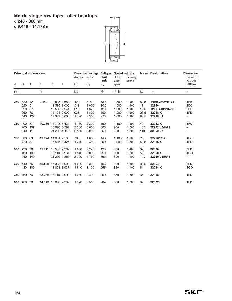
154
Metric single row taper roller bearingsd 240 - 360 mmd 9.449 - 14.173 in
240 320 42 9.449 12.598 1.654 429 815 73.5 1 300 1 900 8.45 T4EB 240/VE174 4EB320 51 12.598 2.008 512 1 080 96.5 1 300 1 900 11 32948 4EC320 57 12.598 2.244 616 1 320 120 1 300 1 900 12.5 T2EE 240/VB406 2EE360 76 14.173 2.992 935 1 800 160 1 200 1 600 27.5 32048 X 4FD440 127 17.323 5.000 1 790 3 350 275 1 000 1 400 83.5 32248 J3 –
260 400 87 10.236 15.748 3.425 1 170 2 200 190 1 100 1 400 40 32052 X 4FC480 137 18.898 5.394 2 200 3 650 300 900 1 200 105 32252 J2/HA1 –540 113 21.260 4.449 2 120 3 050 250 850 1 200 110 30352 J2 –
280 380 63.5 11.024 14.961 2.500 765 1 660 143 1 100 1 600 20 32956/C02 4EC420 87 16.535 3.425 1 210 2 360 200 1 000 1 300 40.5 32056 X 4FC
300 420 76 11.811 16.535 2.992 1 050 2 240 190 950 1 400 32 32960 3FD460 100 18.110 3.937 1 540 3 000 250 900 1 200 58 32060 X 4GD540 149 21.260 5.866 2 750 4 750 365 800 1 100 140 32260 J2/HA1 –
320 440 76 12.598 17.323 2.992 1 080 2 360 196 900 1 300 33.5 32964 3FD480 100 18.898 3.937 1 540 3 100 255 850 1 100 64 32064 X 4GD
340 460 76 13.386 18.110 2.992 1 080 2 400 200 850 1 300 35 32968 4FD
360 480 76 14.173 18.898 2.992 1 120 2 550 204 800 1 200 37 32972 4FD
Principal dimensions Basic load ratings Fatigue Speed ratings Mass Designation Dimensiondynamic static load Refer- Limiting Series to
limit ence speed ISO 355d D T d D T C C0 Pu speed (ABMA)
mm in kN kN r/min kg – –
D d
T

155
25 62 36.5 0.984 2.441 1.437 64.4 80 8.65 6 000 11 000 0.55 31305 J2/QDF
30 72 41.5 1.181 2.835 1.634 93 100 11.4 5 600 9 500 0.85 *31306 J2/QDF
35 80 45.5 1.378 3.150 1.791 120 134 15.6 5 000 8 500 1.1 *31307 J2/QDF
40 90 50.5 1.575 3.543 1.988 146 163 19 4 500 7 500 1.5 *31308 J2/QCL7CDF
45 100 54.5 1.772 3.937 2.146 180 204 24.5 4 000 6 700 2 *31309 J2/QCL7CDF
50 90 43.5 1.969 3.543 1.713 150 183 20.8 4 800 7 500 1.1 *30210 J2/QDF110 58.5 4.331 2.303 208 240 28.5 3 600 6 000 2.6 *31310 J2/QCL7CDF
55 90 54 2.165 3.543 2.126 180 270 30.5 4 500 7 000 1.35 *33011/QDF03C170120 63 4.724 2.480 240 275 33.5 3 400 5 600 3.3 *31311 J2/QDF
60 95 46 2.362 3.740 1.378 163 245 27 4 300 6 700 1.9 *32012 X/QCL7CDFC250110 59.5 4.331 1.890 250 320 37.5 4 000 6 000 2.4 *32212 J2/QDFC290130 67 5.118 2.638 285 335 40.5 3 000 5 300 4.1 31312 J2/QDF
65 120 49.5 2.559 4.724 1.949 228 270 32.5 3 600 5 600 1.2 *30213 J2/QDF140 72 5.512 2.835 325 380 47.5 2 800 4 800 5.05 *31313 J2/QCL7CDF
70 110 50 2.756 4.331 1.496 200 305 34.5 3 800 5 600 1.8 *32014 X/QDF110 62 4.331 2.008 220 400 45.5 3 400 5 600 2.4 33014/DF150 76 5.906 2.992 365 440 54 2 600 4 500 6.15 *31314 J2/QCL7CDF
75 115 62 2.953 4.528 2.441 233 455 52 3 200 5 300 2.4 33015/QDF125 74 4.921 2.913 303 530 63 3 000 5 000 3.8 33115/QDFC150130 54.5 5.118 2.146 238 355 41.5 3 000 5 000 2.85 30215 J2/QDF130 66.5 5.118 2.618 275 425 49 3 000 5 000 3.4 32215 J2/QDF160 80 6.299 3.150 405 490 58.5 2 400 4 300 7.25 *31315 J2/QCL7CDF
80 125 58 3.150 4.921 2.283 233 430 49 3 000 5 000 2.65 32016 X/QDFC165140 70.5 5.512 2.776 319 490 57 2 800 4 500 4.25 32216 J2/QDF170 85 6.693 3.346 440 530 64 2 400 4 000 8.75 31316 J1/QCL7CDF
85 130 58 3.346 5.118 2.283 238 450 51 2 800 4 800 2.8 32017 X/QDF130 72 5.118 2.835 308 620 69.5 2 800 4 800 3.55 33017/QDFC240150 61 5.906 2.402 303 440 51 2 600 4 300 4.3 30217 J2/QDF150 77 5.906 3.031 369 570 65.5 2 600 4 300 5.45 32217 J2/QDF150 98 5.906 3.858 495 850 96.5 2 400 4 300 7.35 33217/QDF180 89 7.087 3.504 413 570 67 2 000 3 800 10 31317 J2/DF
90 140 64 3.543 5.512 2.520 292 540 62 2 600 4 300 3.65 32018 X/QDF140 78 5.512 3.071 369 710 78 2 600 4 500 4.5 33018/QDFC150160 65 6.299 2.559 336 490 57 2 400 4 000 5.15 30218 J2/DF160 85 6.299 3.346 429 680 76.5 2 400 4 000 6.9 32218 J2/QDF190 93 7.480 3.661 457 630 73.5 1 900 3 400 11.5 31318 J2/DF
Principal dimensions Basic load ratings Fatigue Speed ratings Mass Designationdynamic static load Refer- Limiting
limit ence speedd D T d D T C C0 Pu speed
mm in kN kN r/min kg –
Single row taper roller bearingspaired face-to-face
d 25 - 90 mmd 0.984 - 3.543 in
* SKF Explorer bearing
D
T
d

156
Single row taper roller bearingspaired face-to-faced 95 - 170 mmd 3.740 - 6.693 in
95 145 78 3.740 5.709 3.071 380 735 81.5 2 600 4 300 5 33019/QDF170 91 6.693 3.583 484 780 86.5 2 200 3 800 8.45 32219 J2/DF200 99 7.874 3.898 501 710 78 1 800 3 400 13 31319 J2/DF
100 150 64 3.937 5.906 2.520 292 560 62 2 400 4 000 3.95 32020 X/QDF180 74 7.087 2.913 418 640 72 2 200 3 600 7.6 30220 J2/DF180 98 7.087 3.858 539 880 96.5 2 200 3 600 10 32220 J2/DF215 103 8.465 4.055 693 980 106 1 900 3 200 16.5 30320 J2/DFC400215 113 8.465 4.449 644 930 102 1 700 3 000 18 31320 XJ2/DF
105 160 70 4.134 6.299 2.756 347 670 73.5 2 200 3 800 5 32021 X/QDF
110 170 76 4.331 6.693 2.992 402 780 85 2 200 3 600 6.3 32022 X/QDF180 112 7.087 4.409 627 1 250 134 2 000 3 400 11.5 33122/DF200 82 7.874 3.228 523 800 90 2 000 3 200 10.5 30222 J2/DF200 112 7.874 4.409 682 1 140 122 1 900 3 200 14.5 32222 J2/DF240 126 9.449 4.961 781 1 160 125 1 500 2 800 26 31322 XJ2/DF
120 180 76 4.724 7.087 2.992 418 830 88 2 000 3 400 6.75 32024 X/DF180 96 7.087 3.780 495 1 080 112 2 000 3 400 8.65 33024/DFC250215 87 8.465 3.425 583 915 98 1 800 3 000 13 30224 J2/DF215 123 8.465 4.843 792 1 400 146 1 800 3 000 18.5 32224 J2/DF260 119 10.236 4.685 968 1 400 146 1 600 2 600 29.5 30324 J2/DFC600260 136 10.236 5.354 935 1 400 146 1 400 2 400 33.5 31324 XJ2/DF
130 180 64 5.118 7.087 2.520 341 735 76.5 2 000 3 600 4.95 32926/DF200 90 7.874 3.543 539 1 080 110 1 800 3 000 10 32026 X/DF230 87.5 9.055 3.445 627 980 106 1 700 2 800 14.5 30226 J2/DF230 135.5 9.055 5.335 952 1 660 170 1 600 2 800 23 32226 J2/DF280 144 11.024 5.669 1 050 1 560 163 1 300 2 400 40 31326 XJ2/DF
140 210 90 5.512 8.268 3.543 561 1 160 116 1 700 2 800 11 32028 X/DF250 91.5 9.843 3.602 721 1 140 116 1 500 2 600 18 30228 J2/DFC100250 143.5 9.843 5.650 1 100 2 000 200 1 500 2 600 29.5 32228 J2/DF300 154 11.811 6.063 1 190 1 800 176 1 200 2 200 52.5 31328 XJ2/DF
150 225 96 5.906 8.858 3.780 644 1 320 132 1 600 2 600 13.5 32030 X/DF270 98 10.630 3.858 737 1 120 114 1 400 2 400 22.5 30230/DFC350270 154 10.630 6.063 1 250 2 280 224 1 400 2 400 37 32230 J2/DF320 164 12.598 6.457 1 340 2 040 200 1 100 2 000 58.5 31330 XJ2/DF
160 240 102 6.299 9.449 4.016 737 1 560 156 1 500 2 400 16 32032 X/DF290 104 11.417 4.094 913 1 460 143 1 300 2 200 27.5 30232 J2/DF290 168 11.417 6.614 1 510 2 800 265 1 300 2 200 48 32232 J2/DF
170 230 76 6.693 9.055 2.992 484 1 160 110 1 500 2 800 9.2 32934/DFC225260 114 10.236 4.488 880 1 830 180 1 400 2 200 22 32034 X/DF310 182 12.205 7.165 1 720 3 250 300 1 200 2 000 59 32234 J2/DF
Principal dimensions Basic load ratings Fatigue Speed ratings Mass Designationdynamic static load Refer- Limiting
limit ence speedd D T d D T C C0 Pu speed
mm in kN kN r/min kg –
D
T
d

157
180 250 90 7.087 9.843 3.543 605 1 460 137 1 400 2 600 14 32936/DF280 128 11.024 5.039 1 100 2 320 220 1 300 2 000 29.5 32036 X/DF320 114 12.598 4.488 1 010 1 630 160 1 200 2 000 42 30236 J2/DFC300320 182 12.598 7.165 1 720 3 250 300 1 100 1 900 61 32236 J2/DF
190 260 90 7.480 10.236 3.543 616 1 530 143 1 300 2 400 14.5 32938/DF290 128 11.417 5.039 1 120 2 400 224 1 200 2 000 30.5 32038 X/DF340 120 13.386 4.724 1 230 2 000 190 1 100 1 800 50 30238 J2/DFC700
200 310 140 7.874 12.205 5.512 1 280 2 750 255 1 100 1 900 39 32040 X/DF360 128 14.173 5.039 1 340 2 240 212 1 000 1 700 52 30240 J2/DFC570360 208 14.173 8.189 2 090 4 000 360 1 000 1 700 88 32240 J2/DF
220 300 102 8.661 11.811 4.016 842 2 000 183 1 100 2 000 21 32944/DFC300340 152 13.386 5.984 1 540 3 350 300 1 000 1 700 51 32044 X/DF
240 360 152 9.449 14.173 5.984 1 570 3 550 315 950 1 600 54.5 32048 X/DF
260 400 174 10.236 15.748 6.850 1 980 4 400 380 850 1 400 79.5 32052 X/DF
280 420 174 11.024 16.535 6.850 2 050 4 750 400 800 1 300 84.5 32056 X/DF
300 420 152 11.811 16.535 5.984 1 790 4 500 375 800 1 400 65.5 32960/DF
320 480 200 12.598 18.898 7.874 2 640 6 200 510 700 1 100 125 32064 X/DF
Principal dimensions Basic load ratings Fatigue Speed ratings Mass Designationdynamic static load Refer- Limiting
limit ence speedd D T d D T C C0 Pu speed
mm in kN kN r/min kg –
Single row taper roller bearingspaired face-to-face
d 180 - 320 mmd 7.087 - 12.598 in

158
Single row taper roller bearingspaired back-to-backd 40 - 200 mmd 1.575 - 7.874 in
40 90 72 61.5 1.575 3.543 2.835 2.421 170 190 21.6 5 300 8 000 1.9 *30308T72 J2/QDBC220
75 130 70 59.5 2.953 5.118 2.756 2.343 238 355 41.5 3 000 5 000 3.25 30215T70 J2/DBC270130 80 67.5 5.118 3.150 2.657 275 425 49 3 000 5 000 6.8 32215T80 J2/QDB
80 140 78 63.5 3.150 5.512 3.071 2.500 319 490 57 2 800 4 500 4.45 32216T78 J2/QDBC110
85 130 66 52 3.346 5.118 2.598 2.047 238 450 51 2 800 4 800 2.7 32017T66 X/QDB/C280130 70 56 5.118 2.756 2.205 308 620 69.5 2 800 4 800 3.5 33017T70/QDB150 71 58.5 5.906 2.795 2.303 303 440 51 2 600 4 300 4.1 30217T71 J2/QDB
90 190 103 70 3.543 7.480 4.055 2.756 457 630 73.5 1 900 3 400 12.5 31318T103 J2/DB31
100 180 108 88 3.937 7.087 4.252 3.465 539 880 96.5 2 200 3 600 10.5 32220T108 J2/DB180 140 120 7.087 5.512 4.724 539 880 96.5 2 200 3 600 12.5 32220T140 J2/DB11
110 170 84 66 4.331 6.693 3.307 2.598 402 780 85 2 200 3 600 6.5 32022T84 X/QDBC200
120 180 84 66 4.724 7.087 3.307 2.598 418 830 88 2 000 3 400 7 32024T84 X/QDBC200215 146 123 8.465 5.748 4.843 792 1 400 146 1 800 3 000 21 32224T146 J2/DB31C210260 146 134 10.236 5.748 5.276 935 1 400 146 1 400 2 400 35 31324T146 XJ2/DB
130 230 97.5 78 5.118 9.055 3.839 3.071 627 980 106 1 700 2 800 15 30226T97.5 J2/DB280 142 112.5 11.024 5.591 4.429 1 080 1 600 166 1 400 2 400 36.5 30326T142 J2/DB11C150
140 210 130 108 5.512 8.268 5.118 4.252 561 1 160 116 1 700 2 800 12.7 32028T130 X/QDB250 106 86.5 9.843 4.173 3.406 721 1 140 116 1 500 2 600 19.5 30228T106 J2/DB250 158 130.5 9.843 6.220 5.138 1 100 2 000 200 1 500 2 600 31 32228T158 J2/DB
150 270 168 134 5.906 10.630 6.614 5.276 1 250 2 280 224 1 400 2 400 38 32230T168 J2/DB270 248 214 10.630 9.764 8.425 1 250 2 280 224 1 400 2 400 39.5 32230T248 J2/DB31320 179 115 12.598 7.047 4.528 1 340 2 040 200 1 100 2 000 58.5 31330T179 XJ2/DB
160 290 179 145 6.299 11.417 7.047 5.709 1 510 2 800 265 1 300 2 200 52.5 32232T179 J2/DB32C230
170 260 162 134 6.693 10.236 6.378 5.276 880 1 830 180 1 400 2 200 30.5 32034T162 X/DB31
180 250 135 83 7.087 9.843 5.315 3.268 605 1 460 137 1 400 2 600 14.5 32936T135/DBC260280 150 118 11.024 5.906 4.646 1 100 2 320 220 1 300 2 200 29.5 32036T150 X/DB280 150 118 11.024 5.906 4.646 1 100 2 320 220 1 300 2 200 29.5 32036T150 XDB11C150320 196 156 12.598 7.717 6.142 1 720 3 250 300 1 100 1 900 61.5 32236T196 J2/DB32
190 260 102 80 7.480 10.236 4.016 3.150 616 1 530 143 1 300 2 400 15 32938T102/DB31260 122 100 10.236 4.803 3.937 616 1 530 143 1 300 2 400 15.5 32938T122/DBCG290 146 114 11.417 5.748 4.488 1 120 2 400 224 1 200 2 000 31.5 32038T146 X/DB42C220290 146 114 11.417 5.748 4.488 1 120 2 400 224 1 200 2 000 31.5 32038T146 X/DBC220290 183 151 11.417 7.205 5.945 1 120 2 400 224 1 200 2 000 32.5 32038T183 X/DB31C330
200 310 154.5 120.5 7.874 12.205 6.083 4.744 1280 2750 255 1 100 1 900 39.5 32040T154.5 X/DB11C170
Principal dimensions Basic load ratings Fatigue Speed ratings Mass Designationdynamic static load Refer- Limiting
limit ence speedd D T C d D T C C C0 Pu speed
mm in kN kN r/min kg –
dD
T
C
* SKF Explorer bearing

159
220 340 165 127 8.661 13.386 6.496 5.000 1 540 3 550 300 1 000 1 700 52 32044T165 X/DB11C170340 165 127 13.386 6.496 5.000 1 540 3 550 300 1 000 1 700 52 32044T165 X/DB42C220340 165 127 13.386 6.496 5.000 1 540 3 550 300 1 000 1 700 52 32044T165 X/DBC340340 168 130 13.386 6.614 5.118 1 540 3 550 300 1 000 1 700 52 32044T168 X/DB
240 360 172 134 9.449 14.173 6.772 5.276 1 570 3 550 315 950 1 600 56 32048T172 X/DB440 284 230 17.323 11.181 9.055 3 300 6 550 550 800 1 400 180 32248T284 J3/DB
260 400 189 145 10.236 15.748 7.441 5.709 1 980 4 400 380 850 1 400 80.5 32052T189 X/DBC280400 194 150 15.748 7.638 5.906 1 980 4 400 380 850 1 400 80.5 32052T194 X/DB
Principal dimensions Basic load ratings Fatigue Speed ratings Mass Designationdynamic static load Refer- Limiting
limit ence speedd D T C d D T C C C0 Pu speed
mm in kN kN r/min kg –
Single row taper roller bearingspaired back-to-back
d 220 - 260 mmd 8.661 - 10.236 in

160
Single row taper roller bearingspaired in tandemd 55 - 80 mmd 2.165 - 3.150 in
55 115 73 2.165 4.528 2.874 250 325 39 3 400 5 600 3.5 * T7FC 055T73/QCL7CDTC10
60 125 80 2.362 4.921 3.150 305 405 49 3 000 5 300 4.05 * T7FC 060T80/QCL7CDTC10
70 140 83 2.756 5.512 3.268 355 480 55 2 800 4 500 11 * T7FC 070T83/QCL7CDTC10
80 160 98 3.150 6.299 3.858 450 630 71 2 400 4 000 16.5 * T7FC 080T98/QCL7CDTC20
Principal dimensions Basic load ratings Fatigue Speed ratings Mass Designation dynamic static load Refer- Limiting
limit ence speedd D T d D T C C0 Pu speed
mm in kN kN r/min kg –
d
T
D
* SKF Explorer bearing

161
ECB 22240 CCK JA / C3 W33
12
34
5
Spherical Roller Bearings
6
1. Prefixes
ECB Air melt carburized steel, innerring only
BS2 Double row spherical rollerbearing with special dimensionsfor seals
2. Internal Design
CA One-piece machined brasscage of the double-prongedtype, retaining flanges on theinner ring and guide ringcentred on the inner ring.
CAC Same as CA but improvedraceway geometry
CAFA Same as CA but with amachined steel cage.
CC Two, window-type steel cages,flangeless inner ring and guidering centred on the inner ring
E d < 65mm, Two window-typesteel cages, flangeless innerring and guide centred on theinner ring. When d > 65 mm asabove but guide ring centred onthe cages
ECA One-piece machined brasscage of the double-prongedtype, retaining flanges on theinner ring, guide ring centred onthe inner ring and reinforced roller complement
ECAC As ECA but with improvedraceway geometry
ECAF As ECA but with a machinedsteel cage
3. Bore types
- Cylindrical bore no symbolK 1:12 tapered boreK30 1:30 tapered bore
4. Cage Designation/Seals
2CS Nitrile rubber seals on bothsides, bearing filled withmedium temp. extremepressure grease
2CS2* Fluoroelastomer rubber seals on both sides, filled withhi-temp grease*
2CS5 Hydrogenated Acrylonitrile(HNBR) seals on both sidesfilled with 70-100% of Polyureabased hi-temperature grease
F Machined steel cage, ringguided
J Pressed steel cage
JA Hardened steel cage, ringguided
MA Machined brass cage outer ringguided
M2 Machined brass roller guidedcage no guide ring (Vibratingscreens)
Y Pressed brass cage, ringguided
5. Clearance/Tolerance
C1 Clearance < C2C2 Clearance < NormalCN Normal (no symbol)C3 Clearance > NormalC4 Clearance > C3C08 Reduce runout on both
inner and outer rings to ISO P5 (RBEC 5)
VQ 424 Closer tolerances than C08
6. Features
W No relubrication feature on E style bearings
W22 Special reduced outsidediameter tolerance for outer ring
W26 Six lubrication holes in innerring
W31 Bearing inspected to specialquality requirements
W33 Groove and 3 oil holes in outerring
W33X Lubrication groove and sixholes in outer ring
W4 Hi point of eccentricity marked on inner ring or sleeve
W502 Combination of W22 and W33
W509 W26 + W31 + W33
W513 W26 + W33
HA1 Case hardened outer and innerrings
HA3 Case hardened inner rings (AsECB prefix)
VA405 Vibrating screen specification
VA406 As VA405 with PTFE coatedbore
VE552(E) Three equally spaced threaded holes in face of outer ring for hoisting tackle,(E) indicates appropriate liftingeyes supplied
VE553(E) As VE552 but on both side faces.
VA751 / VA759 Both printing press/coater specifications
VT143 Extreme pressure grease
W64 Solid oil filling
W77 Plugged W33 holes
* See warning page 163

162
Boundary Dimensions in accordance with ISO 15:1998
Tolerances SKF spherical roller bearings are manufactured as stan-dard to normal tolerances. SKF Explorer bearings up to315 mm bore diameter are produced to higher precisionthan the ISO normal tolerances. The width tolerance isconsiderably tighter*. The running accuracy is to toleranceclass P5 as standard.For larger bearings P5 tolerances are also available withthe suffix C08 or closer tolerances are available with suffixVQ424.Vibratory bearings are manufactured to; bore P5 and O/D P6.
Heat Stabilization 392 °F (200 °C)
Misalignment series 21300 - 1° series 22200 - 1.5°series 22300 - 2° series 23000 - 1.5°series 23100 - 1.5° series 23200 - 2.5°series 23900 - 1.5° series 24000 - 2°series 24100 - 2.5°
Cage MaterialStandard SteelOptional Machined brass (CA) larger bearings only
Axial Load - max For adapter mounts Fap = 3 x B x dSleeve mounted Where B = bearing width (mm) and d = bearing bore (mm)
Fap = axial load in NewtonsFor cylindrical mounts - contact SKF engineering
Seals 2CS - 2 Nitrile seals with medium temperature grease2CS2 - 2 Fluoroelastomer rubber seals with hightemperature bearings grease2CS5 - 2 Hydrogenated acrylonitrile butadiene rubberseals with hi-temp greasewidth may differ from standard bearings
* See width tolerances on page 704 of the SKF 6000 catalogue
Technical Features
VA405 DesignShaker Screen
Spherical Roller Bearing(data tables on page 176)
SealedSpherical Roller Bearing(data tables on page 174)
StandardSpherical Roller Bearing(data tables on page 166)
Printing PressSpherical Roller Bearing(data tables on page 179)
Spherical roller bearings

Bore Radial internal clearancediameter
d C2 Normal C3 C4 C5
over incl. over incl. min max min max min max min max min max min max min max min max min max min maxmm in µm in µm in µm in µm in µm in
18 24 0.7087 0.9449 10 20 0.0004 0.0008 20 35 0.0008 0.0014 35 45 0.0014 0.0018 45 60 0.0018 0.0024 60 75 0.0024 0.003024 30 0.9449 1.1811 15 25 0.0006 0.0010 25 40 0.0010 0.0016 40 55 0.0016 0.0022 55 75 0.0022 0.0030 75 95 0.0030 0.003730 40 1.1811 1.5748 15 30 0.0006 0.0012 30 45 0.0012 0.0018 45 60 0.0018 0.0024 60 80 0.0024 0.0031 80 100 0.0031 0.0039
40 50 1.5748 1.9685 20 35 0.0008 0.0014 35 55 0.0014 0.0022 55 75 0.0022 0.0030 75 100 0.0030 0.0039 100 125 0.0039 0.004950 65 1.9685 2.5591 20 40 0.0008 0.0016 40 65 0.0016 0.0026 65 90 0.0026 0.0035 90 120 0.0035 0.0047 120 150 0.0047 0.005965 80 2.5591 3.1496 30 50 0.0012 0.0020 50 80 0.0020 0.0031 80 110 0.0031 0.0043 110 145 0.0043 0.0057 145 180 0.0057 0.0071
80 100 3.1496 3.9370 35 60 0.0014 0.0024 60 100 0.0024 0.0039 100 135 0.0039 0.0053 135 180 0.0053 0.0071 180 225 0.0071 0.0089100 120 3.9370 4.7244 40 75 0.0016 0.0030 75 120 0.0030 0.0047 120 160 0.0047 0.0063 160 210 0.0063 0.0083 210 260 0.0083 0.0102120 140 4.7244 5.5118 50 95 0.0020 0.0037 95 145 0.0037 0.0057 145 190 0.0057 0.0075 190 240 0.0075 0.0094 240 300 0.0094 0.0118
140 160 5.5118 6.2992 60 110 0.0024 0.0043 110 170 0.0043 0.0067 170 220 0.0067 0.0087 220 280 0.0087 0.0110 280 350 0.0110 0.0138160 180 6.2992 7.0866 65 120 0.0026 0.0047 120 180 0.0047 0.0071 180 240 0.0071 0.0094 240 310 0.0094 0.0122 310 390 0.0122 0.0154180 200 7.0866 7.8740 70 130 0.0028 0.0051 130 200 0.0051 0.0079 200 260 0.0079 0.0102 260 340 0.0102 0.0134 340 430 0.0134 0.0169
200 225 7.8740 8.8583 80 140 0.0031 0.0055 140 220 0.0055 0.0087 220 290 0.0087 0.0114 290 380 0.0114 0.0150 380 470 0.0150 0.0185225 250 8.8583 9.8425 90 150 0.0035 0.0059 150 240 0.0059 0.0094 240 320 0.0094 0.0126 320 420 0.0126 0.0165 420 520 0.0165 0.0205250 280 9.8425 11.0236 100 170 0.0039 0.0067 170 260 0.0067 0.0102 260 350 0.0102 0.0138 350 460 0.0138 0.0181 460 570 0.0181 0.0224
280 315 11.0236 12.4016 110 190 0.0043 0.0075 190 280 0.0075 0.0110 280 370 0.0110 0.0146 370 500 0.0146 0.0197 500 630 0.0197 0.0248315 355 12.4016 13.9764 120 200 0.0047 0.0079 200 310 0.0079 0.0122 310 410 0.0122 0.0161 410 550 0.0161 0.0217 550 690 0.0217 0.0272355 400 13.9764 15.7480 130 220 0.0051 0.0087 220 340 0.0087 0.0134 340 450 0.0134 0.0177 450 600 0.0177 0.0236 600 750 0.0236 0.0295
400 450 15.7480 17.7165 140 240 0.0055 0.0094 240 370 0.0094 0.0146 370 500 0.0146 0.0197 500 660 0.0197 0.0260 660 820 0.0260 0.0323450 500 17.7165 19.6850 140 260 0.0055 0.0102 260 410 0.0102 0.0161 410 550 0.0161 0.0217 550 720 0.0217 0.0283 720 900 0.0283 0.0354500 560 19.6850 22.0472 150 280 0.0059 0.0110 280 440 0.0110 0.0173 440 600 0.0173 0.0236 600 780 0.0236 0.0307 780 1000 0.0307 0.0394
560 630 22.0472 24.8031 170 310 0.0067 0.0122 310 480 0.0122 0.0189 480 650 0.0189 0.0256 650 850 0.0256 0.0335 850 1100 0.0335 0.0433630 710 24.8031 27.9528 190 350 0.0075 0.0138 350 530 0.0138 0.0209 530 700 0.0209 0.0276 700 920 0.0276 0.0362 920 1190 0.0362 0.0469710 800 27.9528 31.4961 210 390 0.0083 0.0154 390 580 0.0154 0.0228 580 770 0.0228 0.0303 770 1010 0.0303 0.0398 1010 1300 0.0398 0.0512
800 900 31.4961 35.4331 230 430 0.0091 0.0169 430 650 0.0169 0.0256 650 860 0.0256 0.0339 860 1120 0.0339 0.0441 1120 1440 0.0441 0.0567900 1000 35.4331 39.3701 260 480 0.0102 0.0189 480 710 0.0189 0.0280 710 930 0.0280 0.0366 930 1220 0.0366 0.0480 1220 1570 0.0480 0.06181000 1120 39.3701 44.0945 290 530 0.0114 0.0209 530 780 0.0209 0.0307 780 1020 0.0307 0.0402 1020 1330 0.0402 0.0524 1330 1720 0.0524 0.0677
1120 1250 44.0945 49.2126 320 580 0.0126 0.0228 580 860 0.0228 0.0339 860 1120 0.0339 0.0441 1120 1460 0.0441 0.0575 1460 1870 0.0575 0.0736
163
Radial internal clearance of spherical roller bearings with cylindrical bore
Warning:SKF sealed roller bearings that are fittedwith fluoro rubber (elastomer) seals (2CS2)can cause serious bodily injury if usedimproperly. The seals are suitable foroperation up to 392°F (200°C). Afluroelestomer base will resist ignition underany conditions outside special furnacecondition, but if exposure to heat (due tofire or any other conditions) is extreme, e.g.over 572°F (300°C) for more than a brieftime, degradation will occur. Fluoro rubberemits dangerous fumes at temperatures of572°F (300°C) and above. This may occurif the seals are subjected to extreme heatduring dismounting, for example. Once it
has been overheated, fluoro rubber willremain dangerous to handle even when ithas cooled down. This degraded product isa major health and safety danger due tothe evolution of hydrofluoric acid (HF). It isnecessary to handle overheated fluororubber seals carefully; always observesafety instructions and wear goggles andprotective gloves. Under no circumstancesshould material (hot or cold) be allowed tocontact skin. If hands or eyes have comeinto contact with the material or fumes, theyshould be washed or rinsed in plenty ofwater. A doctor should always be consultedespecially if the fumes have been inhaled.
Decontamination can be carried out usinglimewater (calcium hydroxide solution); useof P.V.C. gloves is essential. Afterneutralization, the degraded seal can bedisposed of in a similar manner to an un-degraded one.
The user is responsible for the correcthandling of the seals during bearing life,and for the proper disposal of used seals.Seals of fluoro rubber and bearingsincorporating them are not dangerous tohandle provided they have never beenoverheated.
Spherical roller bearings
MountingInformationPlease go to www.skf.com/mount

164
Bore Radial internal clearancediameterd C2 Normal C3 C4 C5
over incl. over incl. min max min max min max min max min max min max min max min max min max min max
mm in µm in µm in µm in µm in µm in
24 30 0.9449 1.1811 20 30 0.0008 0.0012 30 40 0.0012 0.0016 40 55 0.0016 0.0022 55 75 0.0022 0.0030 - -
30 40 1.1811 1.5748 25 35 0.0010 0.0014 35 50 0.0014 0.0020 50 65 0.0020 0.0026 65 85 0.0026 0.0033 85 105 0.0033 0.0041
40 50 1.5748 1.9685 30 45 0.0012 0.0018 45 60 0.0018 0.0024 60 80 0.0024 0.0031 80 100 0.0031 0.0039 100 130 0.0039 0.0051
50 65 1.9685 2.5591 40 55 0.0016 0.0022 55 75 0.0022 0.0030 75 95 0.0030 0.0037 95 120 0.0037 0.0047 120 160 0.0047 0.0063
65 80 2.5591 3.1496 50 70 0.0020 0.0028 70 95 0.0028 0.0037 95 120 0.0037 0.0047 120 150 0.0047 0.0059 150 200 0.0059 0.0079
80 100 3.1496 3.9370 55 80 0.0022 0.0031 80 110 0.0031 0.0043 110 140 0.0043 0.0055 140 180 0.0055 0.0071 180 230 0.0071 0.0091
100 120 3.9370 4.7244 65 100 0.0026 0.0039 100 135 0.0039 0.0053 135 170 0.0053 0.0067 170 220 0.0067 0.0087 220 280 0.0087 0.0110
120 140 4.7244 5.5118 80 120 0.0031 0.0047 120 160 0.0047 0.0063 160 200 0.0063 0.0079 200 260 0.0079 0.0102 260 330 0.0102 0.0130
140 160 5.5118 6.2992 90 130 0.0035 0.0051 130 180 0.0051 0.0071 180 230 0.0071 0.0091 230 300 0.0091 0.0118 300 380 0.0118 0.0150
160 180 6.2992 7.0866 100 140 0.0039 0.0055 140 200 0.0055 0.0079 200 260 0.0079 0.0102 260 340 0.0102 0.0134 340 430 0.0134 0.0169
180 200 7.0866 7.8740 110 160 0.0043 0.0063 160 220 0.0063 0.0087 220 290 0.0087 0.0114 290 370 0.0114 0.0146 370 470 0.0146 0.0185
200 225 7.8740 8.8583 120 180 0.0047 0.0071 180 250 0.0071 0.0098 250 320 0.0098 0.0126 320 410 0.0126 0.0161 410 520 0.0161 0.0205
225 250 8.8583 9.8425 140 200 0.0055 0.0079 200 270 0.0079 0.0106 270 350 0.0106 0.0138 350 450 0.0138 0.0177 450 570 0.0177 0.0224
250 280 9.8425 11.0236 150 220 0.0059 0.0087 220 300 0.0087 0.0118 300 390 0.0118 0.0154 390 490 0.0154 0.0193 490 620 0.0193 0.0244
280 315 11.0236 12.4016 170 240 0.0067 0.0094 240 330 0.0094 0.0130 330 430 0.0130 0.0169 430 540 0.0169 0.0213 540 680 0.0213 0.0268
315 355 12.4016 13.9764 190 270 0.0075 0.0106 270 360 0.0106 0.0142 360 470 0.0142 0.0185 470 590 0.0185 0.0232 590 740 0.0232 0.0291
355 400 13.9764 15.7480 210 300 0.0083 0.0118 300 400 0.0118 0.0157 400 520 0.0157 0.0205 520 650 0.0205 0.0256 650 820 0.0256 0.0323
400 450 15.7480 17.7165 230 330 0.0091 0.0130 330 440 0.0130 0.0173 440 570 0.0173 0.0224 570 720 0.0224 0.0283 720 910 0.0283 0.0358
450 500 17.7165 19.6850 260 370 0.0102 0.0146 370 490 0.0146 0.0193 490 630 0.0193 0.0248 630 790 0.0248 0.0311 790 1000 0.0311 0.0394
500 560 19.6850 22.0472 290 410 0.0114 0.0161 410 540 0.0161 0.0213 540 680 0.0213 0.0268 680 870 0.0268 0.0343 870 1100 0.0343 0.0433
560 630 22.0472 24.8031 320 460 0.0126 0.0181 460 600 0.0181 0.0236 600 760 0.0236 0.0299 760 980 0.0299 0.0386 980 1230 0.0386 0.0484
630 710 24.8031 27.9528 350 510 0.0138 0.0201 510 670 0.0201 0.0264 670 850 0.0264 0.0335 850 1090 0.0335 0.0429 1090 1360 0.0429 0.0535
710 800 27.9528 31.4961 390 570 0.0154 0.0224 570 750 0.0224 0.0295 750 960 0.0295 0.0378 960 1220 0.0378 0.0480 1220 1500 0.0480 0.0591
800 900 31.4961 35.4331 440 640 0.0173 0.0252 640 840 0.0252 0.0331 840 1070 0.0331 0.0421 1070 1370 0.0421 0.0539 1370 1690 0.0539 0.0665
900 1000 35.4331 39.3701 490 710 0.0193 0.0280 710 930 0.0280 0.0366 930 1190 0.0366 0.0469 1190 1520 0.0469 0.0598 1520 1860 0.0598 0.0732
1000 1120 39.3701 44.0945 530 770 0.0209 0.0303 770 1030 0.0303 0.0406 1030 1300 0.0406 0.0512 1300 1670 0.0512 0.0657 1670 2050 0.0657 0.0807
1120 1250 44.0945 49.2126 570 830 0.0224 0.0327 830 1120 0.0327 0.0441 1120 1420 0.0441 0.0559 1420 1830 0.0559 0.0720 1830 2250 0.0720 0.0886
Radial internal clearance of spherical roller bearings with tapered bore
Spherical roller bearings

165
Spherical roller bearings

* 22205/20 E –
* 22205 E * 22205 EK21305 CC –
* 22206 E * 22206 EK21306 CC 21306 CCK
* 22207 E * 22207 EK21307 CC 21307 CCK
* 22208 E * 22208 EK* 21308 E * 21308 EK* 22308 E * 22308 EK
* 22209 E * 22209 EK* 21309 E * 21309 EK* 22309 E * 22309 EK
* 22210 E * 22210 EK* 21310 E * 21310 EK* 22310 E * 22310 EK
* 22211 E * 22211 EK* 21311 E * 21311 EK* 22311 E * 22311 EK
* 22212 E * 22212 EK* 21312 E * 21312 EK* 22312 E * 22312 EK
* 24013 CC/W33 * 24013 CCK30/W33* 22213 E * 22213 EK* 21313 E * 21313 EK* 22313 E * 22313 EK
* 22214 E * 22214 EK* 21314 E * 21314 EK* 22314 E * 22314 EK
* 24015 CC/W33 * 24015 CCK30/W33* 22215 E * 22215 EK* 21315 E * 21315 EK* 22315 E * 22315 EK
* 22216 E * 22216 EK* 21316 E * 21316 EK* 22316 E * 22316 EK
* 22217 E * 22217 EK* 21317 E * 21317 EK* 22317 E * 22317 EK
* 22218 E * 22218 EK* 23218 CC/W33 * 23218 CCK/W33* 21318 E * 21318 EK* 22318 E * 22318 EK
2.047 0.709 49 44 4.75 13 000 17 000 0.28
2.047 0.709 49 44 4.75 13 000 17 000 0.262.441 0.669 41.4 41.5 4.55 8 500 12 000 0.28
2.441 0.787 64 60 6.4 10 000 14 000 0.292.835 0.748 55.2 61 6.8 7 500 10 000 0.41
2.835 0.906 86.5 85 9.3 9 000 12 000 0.453.150 0.827 65.6 72 8.15 6 700 9 500 0.55
3.150 0.906 96.5 90 9.8 8 000 11 000 0.533.543 0.906 104 108 11.8 7 000 9 500 0.753.543 1.299 150 140 15 6 000 8 000 1.05
3.346 0.906 102 98 10.8 7 500 10 000 0.583.937 0.984 125 127 13.7 6 300 8 500 0.993.937 1.417 183 183 19.6 5 300 7 000 1.4
3.543 0.906 104 108 11.8 7 000 9 500 0.634.331 1.063 156 166 18.6 5 600 7 500 1.354.331 1.575 220 224 24 4 800 6 300 1.9
3.937 0.984 125 127 13.7 6 300 8 500 0.844.724 1.142 156 166 18.6 5 600 7 500 1.74.724 1.693 270 280 30 4 300 5 600 2.45
4.331 1.102 156 166 18.6 5 600 7 500 1.155.118 1.220 212 240 26.5 4 800 6 300 2.15.118 1.811 310 335 36.5 4 000 5 300 3.1
3.394 1.378 132 173 20.4 4 300 6 300 0.954.724 1.220 193 216 24 5 000 7 000 1.555.512 1.299 236 270 29 4 300 6 000 2.555.512 1.890 340 360 38 3 800 5 000 3.75
4.921 1.220 208 228 25.5 5 000 6 700 1.555.906 1.378 285 325 34.5 4 000 5 600 3.15.906 2.008 400 430 45 3 400 4 500 4.55
4.528 1.575 173 232 28.5 3 800 5 300 1.555.118 1.220 212 240 26.5 4 800 6 300 1.76.299 1.457 285 325 34.5 4 000 5 600 3.756.299 2.165 440 475 48 3 200 4 300 5.55
5.512 1.299 236 270 29 4 300 6 000 2.16.693 1.535 325 375 39 3 800 5 300 4.456.693 2.283 490 540 54 3 000 4 000 6.6
5.906 1.417 285 325 34.5 4 000 5 600 2.657.087 1.614 325 375 39 3 800 5 300 5.27.087 2.362 550 620 61 2 800 3 800 7.65
6.299 1.575 325 375 39 3 800 5 300 3.46.299 2.063 355 440 48 2 800 3 800 4.657.480 1.693 380 450 46.5 3 600 4 800 6.17.480 2.520 610 695 67 2 600 3 600 9.05
20
25
30
35
40
45
50
55
60
65
70
75
80
85
90
Principal dimensions Basic load Fatigue Speed ratings Mass Designationsratings load Refer- Limiting Bearing withdynamic static limit ence speed cylindrical bore tapered bore
d D B d D B C C0 Pu speed
mm in kN kN r/min kg –
52 18
52 1862 17
62 2072 19
72 2380 21
80 2390 2390 33
85 23100 25100 36
90 23110 27110 40
100 25120 29120 43
110 28130 31130 46
100 35120 31140 33140 48
125 31150 35150 51
115 40130 31160 37160 55
140 33170 39170 58
150 36180 41180 60
160 40160 52.4190 43190 64
166
0.787
0.984
1.181
1.378
1.575
1.772
1.969
2.165
2.362
2.559
2.756
2.953
3.150
3.346
3.543
Spherical roller bearingsd 20 - 90 mmd 0.787 - 3.543 in
* SKF Explorer bearing
D
B
d d

Spherical roller bearingsd 95 - 140 mm
d 3.740 - 5.512 in
* SKF Explorer bearing
* 22219 E * 22219 EK* 21319 E * 21319 EK* 22319 E * 22319 EK
* 24020 CC/W33 * 24020 CCK30/W33* 23120 CC/W33 * 23120 CCK/W33* 24120 CC/W33 * 24120 CCK30/W33
* 22220 E * 22220 EK* 23220 CC/W33 * 23220 CCK/W33* 21320 E * 21320 EK* 22320 E * 22320 EK
* 23022 CC/W33 * 23022 CCK/W33* 24022 CC/W33 * 24022 CCK30/W33* 23122 CC/W33 * 23122 CCK/W33* 24122 CC/W33 * 24122 CCK30/W33
* 22222 E * 22222 EK* 23222 CC/W33 * 23222 CCK/W33* 22322 E * 22322 EK
* 23024 CC/W33 * 23024 CCK/W33* 24024 CC/W33 * 24024 CCK30/W33* 23124 CC/W33 * 23124 CCK/W33* 24124 CC/W33 * 24124 CCK30/W33
* 22224 E * 22224 EK* 23224 CC/W33 * 23224 CCK/W33* 22324 CC/W33 * 22324 CCK/W33
* 23026 CC/W33 * 23026 CCK/W33* 24026 CC/W33 * 24026 CCK30/W33* 23126 CC/W33 * 23126 CCK/W33* 24126 CC/W33 * 24126 CCK30/W33
* 22226 E * 22226 EK* 23226 CC/W33 * 23226 CCK/W33* 22326 CC/W33 * 22326 CCK/W33
* 23028 CC/W33 * 23028 CCK/W33* 24028 CC/W33 * 24028 CCK30/W33* 23128 CC/W33 * 23128 CCK/W33* 24128 CC/W33 * 24128 CCK30/W33
* 22228 CC/W33 * 22228 CCK/W33* 23228 CC/W33 * 23228 CCK/W33* 22328 CC/W33 * 22328 CCK/W33
6.693 1.693 380 450 46.5 3 600 4 800 4.157.874 1.772 425 490 49 3 400 4 500 7.057.874 2.638 670 765 73.5 2 600 3 400 10.5
5.906 1.969 285 415 45.5 2 800 4 000 3.156.496 2.047 365 490 53 3 000 4 000 4.556.496 2.559 455 640 68 2 400 3 200 5.65
7.087 1.811 425 490 49 3 400 4 500 4.97.087 2.374 475 600 63 2 400 3 400 6.858.465 1.850 425 490 49 3 400 4 500 8.68.465 2.874 815 950 88 2 400 3 000 13.5
6.693 1.772 310 440 46.5 3 400 4 300 3.86.693 2.362 415 620 67 2 400 3 600 57.087 2.205 430 585 61 2 800 3 600 5.757.087 2.717 520 750 78 2 200 3 000 7.1
7.874 2.087 560 640 63 3 000 4 000 77.874 2.748 600 765 76.5 2 200 3 200 9.859.449 3.150 950 1120 100 2 000 2 800 18.4
7.087 1.811 355 510 53 3 200 4 000 4.27.087 2.362 430 670 68 2 400 3 400 5.457.874 2.441 510 695 71 2 600 3 400 87.874 3.150 655 950 95 1 900 2 600 10.3
8.465 2.283 630 765 73.5 2 800 3 800 8.78.465 2.992 695 930 93 2 000 2 800 1210.236 3.386 965 1120 100 2 000 2 600 23
7.874 2.047 430 610 62 2 800 3 600 67.874 2.717 540 815 81.5 2 000 3 000 8.058.268 2.520 560 780 78 2 400 3 200 8.88.268 3.150 680 1000 100 1 800 2 400 11
9.055 2.520 735 930 88 2 600 3 600 119.055 3.150 780 1060 104 1 900 2 600 14.511.024 3.661 1 120 1 320 114 1 800 2 400 29
8.268 2.087 465 680 68 2 600 3 400 6.558.268 2.717 570 900 88 2 000 2 800 8.558.858 2.677 630 900 88 2 200 2 800 10.58.858 3.346 765 1 160 112 1 700 2 400 13.5
9.843 2.677 710 900 86.5 2 400 3 200 149.843 3.465 915 1 250 120 1 700 2 400 1911.811 4.016 1 290 1 560 132 1 700 2 200 36.5
95
100
110
120
130
140
167
170 43200 45200 67
150 50165 52165 65
180 46180 60.3215 47215 73
170 45170 60180 56180 69
200 53200 69.8240 80
180 46180 60200 62200 80
215 58215 76260 86
200 52200 69210 64210 80
230 64230 80280 93
210 53210 69225 68225 85
250 68250 88300 102
Principal dimensions Basic load Fatigue Speed ratings Mass Designationsratings load Refer- Limiting Bearing withdynamic static limit ence speed cylindrical bore tapered bore
d D B d D B C C0 Pu speed
mm in kN kN r/min kg –
3.740
3.937
4.331
4.724
5.118
5.512
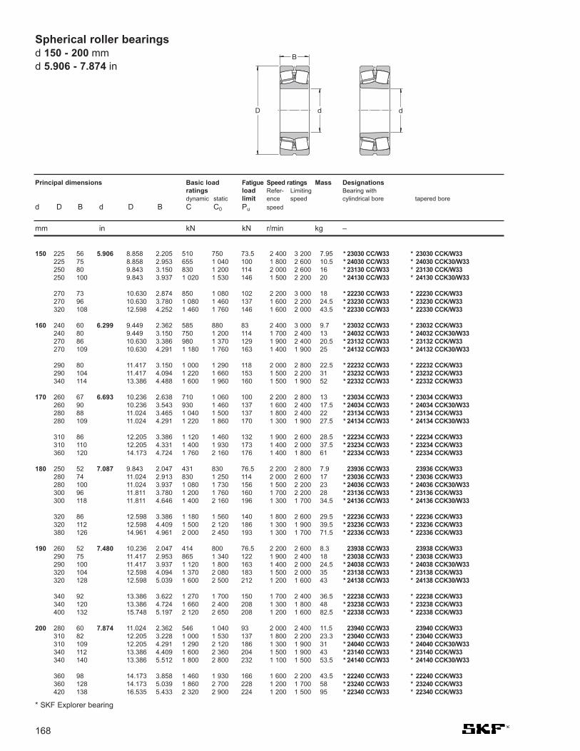
* 23030 CC/W33 * 23030 CCK/W33* 24030 CC/W33 * 24030 CCK30/W33* 23130 CC/W33 * 23130 CCK/W33* 24130 CC/W33 * 24130 CCK30/W33
* 22230 CC/W33 * 22230 CCK/W33* 23230 CC/W33 * 23230 CCK/W33* 22330 CC/W33 * 22330 CCK/W33
* 23032 CC/W33 * 23032 CCK/W33* 24032 CC/W33 * 24032 CCK30/W33* 23132 CC/W33 * 23132 CCK/W33* 24132 CC/W33 * 24132 CCK30/W33
* 22232 CC/W33 * 22232 CCK/W33* 23232 CC/W33 * 23232 CCK/W33* 22332 CC/W33 * 22332 CCK/W33
* 23034 CC/W33 * 23034 CCK/W33* 24034 CC/W33 * 24034 CCK30/W33* 23134 CC/W33 * 23134 CCK/W33* 24134 CC/W33 * 24134 CCK30/W33
* 22234 CC/W33 * 22234 CCK/W33* 23234 CC/W33 * 23234 CCK/W33* 22334 CC/W33 * 22334 CCK/W33
23936 CC/W33 23936 CCK/W33* 23036 CC/W33 * 23036 CCK/W33* 24036 CC/W33 * 24036 CCK30/W33* 23136 CC/W33 * 23136 CCK/W33* 24136 CC/W33 * 24136 CCK30/W33
* 22236 CC/W33 * 22236 CCK/W33* 23236 CC/W33 * 23236 CCK/W33* 22336 CC/W33 * 22336 CCK/W33
23938 CC/W33 23938 CCK/W33* 23038 CC/W33 * 23038 CCK/W33* 24038 CC/W33 * 24038 CCK30/W33* 23138 CC/W33 * 23138 CCK/W33* 24138 CC/W33 * 24138 CCK30/W33
* 22238 CC/W33 * 22238 CCK/W33* 23238 CC/W33 * 23238 CCK/W33* 22338 CC/W33 * 22338 CCK/W33
23940 CC/W33 23940 CCK/W33* 23040 CC/W33 * 23040 CCK/W33* 24040 CC/W33 * 24040 CCK30/W33* 23140 CC/W33 * 23140 CCK/W33* 24140 CC/W33 * 24140 CCK30/W33
* 22240 CC/W33 * 22240 CCK/W33* 23240 CC/W33 * 23240 CCK/W33* 22340 CC/W33 * 22340 CCK/W33
8.858 2.205 510 750 73.5 2 400 3 200 7.958.858 2.953 655 1 040 100 1 800 2 600 10.59.843 3.150 830 1 200 114 2 000 2 600 169.843 3.937 1 020 1 530 146 1 500 2 200 20
10.630 2.874 850 1 080 102 2 200 3 000 1810.630 3.780 1 080 1 460 137 1 600 2 200 24.512.598 4.252 1 460 1 760 146 1 600 2 000 43.5
9.449 2.362 585 880 83 2 400 3 000 9.79.449 3.150 750 1 200 114 1 700 2 400 1310.630 3.386 980 1 370 129 1 900 2 400 20.510.630 4.291 1 180 1 760 163 1 400 1 900 25
11.417 3.150 1 000 1 290 118 2 000 2 800 22.511.417 4.094 1 220 1 660 153 1 500 2 200 3113.386 4.488 1 600 1 960 160 1 500 1 900 52
10.236 2.638 710 1 060 100 2 200 2 800 1310.236 3.543 930 1 460 137 1 600 2 400 17.511.024 3.465 1 040 1 500 137 1 800 2 400 2211.024 4.291 1 220 1 860 170 1 300 1 900 27.5
12.205 3.386 1 120 1 460 132 1 900 2 600 28.512.205 4.331 1 400 1 930 173 1 400 2 000 37.514.173 4.724 1 760 2 160 176 1 400 1 800 61
9.843 2.047 431 830 76.5 2 200 2 800 7.911.024 2.913 830 1 250 114 2 000 2 600 1711.024 3.937 1 080 1 730 156 1 500 2 200 2311.811 3.780 1 200 1 760 160 1 700 2 200 2811.811 4.646 1 400 2 160 196 1 300 1 700 34.5
12.598 3.386 1 180 1 560 140 1 800 2 600 29.512.598 4.409 1 500 2 120 186 1 300 1 900 39.514.961 4.961 2 000 2 450 193 1 300 1 700 71.5
10.236 2.047 414 800 76.5 2 200 2 600 8.311.417 2.953 865 1 340 122 1 900 2 400 1811.417 3.937 1 120 1 800 163 1 400 2 000 24.512.598 4.094 1 370 2 080 183 1 500 2 000 3512.598 5.039 1 600 2 500 212 1 200 1 600 43
13.386 3.622 1 270 1 700 150 1 700 2 400 36.513.386 4.724 1 660 2 400 208 1 300 1 800 4815.748 5.197 2 120 2 650 208 1 200 1 600 82.5
11.024 2.362 546 1 040 93 2 000 2 400 11.512.205 3.228 1 000 1 530 137 1 800 2 200 23.312.205 4.291 1 290 2 120 186 1 300 1 900 3113.386 4.409 1 600 2 360 204 1 500 1 900 4313.386 5.512 1 800 2 800 232 1 100 1 500 53.5
14.173 3.858 1 460 1 930 166 1 600 2 200 43.514.173 5.039 1 860 2 700 228 1 200 1 700 5816.535 5.433 2 320 2 900 224 1 200 1 500 95
Spherical roller bearingsd 150 - 200 mmd 5.906 - 7.874 in
150
160
170
180
190
200
Principal dimensions Basic load Fatigue Speed ratings Mass Designationsratings load Refer- Limiting Bearing withdynamic static limit ence speed cylindrical bore tapered bore
d D B d D B C C0 Pu speed
mm in kN kN r/min kg –
D
B
d d
225 56225 75250 80250 100
270 73270 96320 108
240 60240 80270 86270 109
290 80290 104340 114
260 67260 90280 88280 109
310 86310 110360 120
250 52280 74280 100300 96300 118
320 86320 112380 126
260 52290 75290 100320 104320 128
340 92340 120400 132
280 60310 82310 109340 112340 140
360 98360 128420 138
168
5.906
6.299
6.693
7.087
7.480
7.874
* SKF Explorer bearing

* SKF Explorer bearing
Spherical roller bearingsd 220 - 300 mm
d 8.661 - 11.811 in
23944 CC/W33 23944 CCK/W33* 23044 CC/W33 * 23044 CCK/W33* 24044 CC/W33 * 24044 CCK30/W33* 23144 CC/W33 * 23144 CCK/W33* 24144 CC/W33 * 24144 CCK30/W33
* 22244 CC/W33 * 22244 CCK/W33* 23244 CC/W33 * 23244 CCK/W33* 22344 CC/W33 * 22344 CCK/W33
23948 CC/W33 23948 CCK/W33* 23048 CC/W33 * 23048 CCK/W33* 24048 CC/W33 * 24048 CCK30/W33* 23148 CC/W33 * 23148 CCK/W33* 24148 CC/W33 * 24148 CCK30/W33
* 22248 CC/W33 * 22248 CCK/W33* 23248 CC/W33 * 23248 CCK/W33* 22348 CC/W33 * 22348 CCK/W33
23952 CC/W33 23952 CCK/W33* 23052 CC/W33 * 23052 CCK/W33* 24052 CC/W33 * 24052 CCK30/W33* 23152 CC/W33 * 23152 CCK/W33* 24152 CC/W33 * 24152 CCK30/W33
* 22252 CC/W33 * 22252 CCK/W33* 23252 CC/W33 * 23252 CCK/W33* 22352 CC/W33 * 22352 CCK/W33
23956 CC/W33 23956 CCK/W33* 23056 CC/W33 * 23056 CCK/W33* 24056 CC/W33 * 24056 CCK30/W33* 23156 CC/W33 * 23156 CCK/W33* 24156 CC/W33 * 24156 CCK30/W33
* 22256 CC/W33 * 22256 CCK/W33* 23256 CC/W33 * 23256 CCK/W33* 22356 CC/W33 * 22356 CCK/W33
23860 CAMA 23860 CAKMA23960 CC/W33 23960 CCK/W33
* 23060 CC/W33 * 23060 CCK/W33* 24060 CC/W33 * 24060 CCK30/W33
* 23160 CC/W33 * 23160 CCK/W33* 24160 CC/W33 * 24160 CCK30/W33* 22260 CC/W33 * 22260 CCK/W33* 23260 CC/W33 * 23260 CCK/W33
11.811 2.362 546 1 080 93 1 900 2 200 12.513.386 3.543 1 220 1 860 163 1 600 2 000 30.513.386 4.646 1 560 2 600 212 1 200 1 700 4014.567 4.724 1 800 2 750 232 1 300 1 700 53.514.567 5.906 2 120 3 350 285 1 000 1 400 67
15.748 4.252 1 760 2 360 196 1 500 2 000 60.515.748 5.669 2 360 3 450 285 1 100 1 500 81.518.110 5.709 2 700 3 450 260 1 000 1 400 120
12.598 2.362 564 1 160 98 1 700 2 000 13.514.173 3.622 1 290 2 080 176 1 500 1 900 33.514.173 4.646 1 600 2 700 228 1 100 1 600 4315.748 5.039 2 080 3 200 255 1 200 1 600 66.515.748 6.299 2 400 3 900 320 900 1 300 83
17.323 4.724 2 200 3 000 245 1 300 1 800 8317.323 6.299 2 900 4 300 345 950 1 300 11019.685 6.102 3 100 4 000 290 950 1 300 155
14.173 2.953 880 1 800 156 1 500 1 900 23.515.748 4.094 1 600 2 550 212 1 300 1 700 48.515.748 5.512 2 040 3 450 285 1 000 1 400 65.517.323 5.669 2 550 3 900 290 1 100 1 400 90.517.323 7.087 3 000 4 800 380 850 1 200 110
18.898 5.118 2 650 3 550 285 1 200 1 600 11018.898 6.850 3 250 4 750 360 850 1 200 14021.260 6.496 3 550 4 550 325 850 1 100 190
14.961 2.953 845 1 760 143 1 400 1 700 2516.535 4.173 1 730 2 850 224 1 300 1 600 52.516.535 5.512 2 160 3 800 285 950 1 400 69.518.110 5.748 2 650 4 250 335 1 000 1 300 9718.110 7.087 3 100 5 100 415 800 1 100 120
19.685 5.118 2 700 3 750 300 1 100 1 500 11519.685 6.929 3 250 4 900 365 800 1 100 15022.835 6.890 4 000 5 200 365 800 1 100 235
14.961 2.362 656 1 600 137 1 400 1 700 16.516.535 3.543 1 200 2 500 200 1 300 1 600 39.518.110 4.646 2 120 3 450 265 1 200 1 500 71.518.110 6.299 2 700 4 750 355 850 1 200 97
19.685 6.299 3 200 5 100 380 950 1 200 12519.685 7.874 3 750 6 300 465 700 1 000 16021.260 5.512 3 150 4 250 325 1 000 1 400 14521.260 7.559 3 900 5 850 425 750 1 000 190
220
240
260
280
300
169
300 60340 90340 118370 120370 150
400 108400 144460 145
320 60360 92360 118400 128400 160
440 120440 160500 155
360 75400 104400 140440 144440 180
480 130480 174540 165
380 75420 106420 140460 146460 180
500 130500 176580 175
380 60420 90460 118460 160
500 160500 200540 140540 192
Principal dimensions Basic load Fatigue Speed ratings Mass Designationsratings load Refer- Limiting Bearing withdynamic static limit ence speed cylindrical bore tapered bore
d D B d D B C C0 Pu speed
mm in kN kN r/min kg –
8.661
9.449
10.236
11.024
11.811

* 23964 CC/W33 * 23964 CCK/W33* 23064 CC/W33 * 23064 CCK/W33* 24064 CC/W33 * 24064 CCK30/W33
* 23164 CC/W33 * 23164 CCK/W33* 24164 CC/W33 * 24164 CCK30/W33* 22264 CC/W33 * 22264 CCK/W33* 23264 CC/W33 * 23264 CCK/W33
* 23968 CC/W33 * 23968 CCK/W33* 23068 CC/W33 * 23068 CCK/W33* 24068 CC/W33 * 24068 CCK30/W33
* 23168 CC/W33 * 23168 CCK/W33* 24168 ECCJ/W33 * 24168 ECCK30J/W33* 23268 CA/W33 * 23268 CAK/W33
* 23972 CC/W33 * 23972 CCK/W33* 23072 CC/W33 * 23072 CCK/W33* 24072 CC/W33 * 24072 CCK30/W33
* 23172 CC/W33 * 23172 CCK/W33* 24172 ECCJ/W33 * 24172 ECCK30J/W33* 22272 CA/W33 * 22272 CAK/W33* 23272 CA/W33 * 23272 CAK/W33
* 23976 CC/W33 * 23976 CCK/W33* 23076 CC/W33 * 23076 CCK/W33* 24076 CC/W33 * 24076 CCK30/W33
* 23176 CA/W33 * 23176 CAK/W33* 24176 ECA/W33 * 24176 ECAK30/W33* 23276 CA/W33 * 23276 CAK/W33
* 23980 CC/W33 * 23980 CCK/W33* 23080 CC/W33 * 23080 CCK/W33* 24080 ECCJ/W33 * 24080 ECCK30J/W33
* 23180 CA/W33 * 23180 CAK/W33* 24180 ECA/W33 * 24180 ECAK30/W33* 23280 CA/W33 * 23280 CAK/W33* 22380 CA/W33 * 22380 CAK/W33
* 23984 CC/W33 * 23984 CCK/W33* 23084 CA/W33 * 23084 CAK/W33* 24084 ECA/W33 * 24084 ECAK30/W33
* 23184 CJ/W33 * 23184 CKJ/W33* 24184 ECA/W33 * 24184 ECAK30/W33* 23284 CA/W33 * 23284 CAK/W33
17.323 3.543 1 430 2 700 212 1 400 1 500 4218.898 4.764 2 240 3 800 285 1 100 1 400 7818.898 6.299 2 850 5 100 400 800 1 200 100
21.260 6.929 3 750 6 000 440 850 1 100 16521.260 8.583 4 250 7 100 510 670 900 21022.835 5.906 3 600 4 900 375 950 1 300 17522.835 8.189 4 400 6 700 480 700 950 240
18.110 3.543 1 460 2 800 216 1 300 1 400 45.520.472 5.236 2 700 4 550 335 1 000 1 300 10520.472 7.087 3 450 6 200 475 750 1 100 140
22.835 7.480 4 250 6 800 480 800 1 000 21022.835 9.567 5 300 8 650 630 600 850 28024.409 8.819 5 100 7 800 550 560 800 295
18.898 3.543 1 400 2 750 220 1 200 1 300 4321.260 5.276 2 750 4 800 345 950 1 200 11021.260 7.087 3 550 6 550 490 700 1 000 145
23.622 7.559 4 300 6 950 490 750 1 000 22023.622 9.567 5 600 9 300 670 560 800 27025.591 6.693 4 300 6 200 440 630 850 25525.591 9.134 5 400 8 300 570 530 750 335
20.472 4.173 1 960 3 800 285 1 100 1 200 6922.047 5.315 2 900 5 000 360 900 1 200 11522.047 7.087 3 600 6 800 480 670 950 150
24.409 7.638 4 400 7 100 500 560 1 000 23024.409 9.567 5 700 9 800 710 480 850 30026.772 9.449 5 850 9 150 620 500 750 375
21.260 4.173 2 000 3 900 290 1 100 1 200 7123.622 5.827 3 250 5 700 400 850 1 100 15023.622 7.874 4 300 8 000 560 630 900 205
25.591 7.874 4 650 7 650 530 530 950 26525.591 9.843 6 200 10 600 735 430 800 34028.346 10.079 6 550 10 400 680 480 670 45032.283 9.567 7 500 10 400 670 430 750 650
22.047 4.173 2 040 4 150 300 1 000 1 100 74.524.409 5.906 3 400 6 000 415 600 1 100 15524.409 7.874 4 400 8 300 585 530 900 210
27.559 8.819 5 600 9 300 620 480 900 35027.559 11.024 7 350 12 600 850 400 700 44529.921 10.709 7 350 11 600 765 450 630 535
Spherical roller bearingsd 320 - 420 mmd 12.598 - 16.535 in
320
340
360
380
400
420
Principal dimensions Basic load Fatigue Speed ratings Mass Designationsratings load Refer- Limiting Bearing withdynamic static limit ence speed cylindrical bore tapered bore
d D B d D B C C0 Pu speed
mm in kN kN r/min kg –
D
B
d d
440 90480 121480 160
540 176540 218580 150580 208
460 90520 133520 180
580 190580 243620 224
480 90540 134540 180
600 192600 243650 170650 232
520 106560 135560 180
620 194620 243680 240
540 106600 148600 200
650 200650 250720 256820 243
560 106620 150620 200
700 224700 280760 272
170
12.598
13.386
14.173
14.961
15.748
16.535
* SKF Explorer bearing

* SKF Explorer bearing
Spherical roller bearingsd 440 - 560 mm
d 17.323 - 22.047 in
* 23988 CC/W33 * 23988 CCK/W33* 23088 CA/W33 * 23088 CAK/W33* 24088 ECA/W33 * 24088 ECAK30/W33
* 23188 CA/W33 * 23188 CAK/W33* 24188 ECA/W33 * 24188 ECAK30/W33* 23288 CA/W33 * 23288 CAK/W33
24892 CAMA/W20 24892 CAK30MA/W20* 23992 CA/W33 * 23992 CAK/W33* 23092 CA/W33 * 23092 CAK/W33* 24092 ECA/W33 * 24092 ECAK30/W33
* 23192 CA/W33 * 23192 CAK/W33* 24192 ECA/W33 * 24192 ECAK30/W33* 23292 CA/W33 * 23292 CAK/W33
23896 CAMA/W20 23896 CAKMA/W20* 23996 CA/W33 * 23996 CAK/W33* 23096 CA/W33 * 23096 CAK/W33* 24096 ECA/W33 * 24096 ECAK30/W33
* 23196 CA/W33 * 23196 CAK/W33* 24196 ECA/W33 * 24196 ECAK30/W33* 23296 CA/W33 * 23296 CAK/W33
238/500 CAMA/W20 238/500 CAKMA/W20* 239/500 CA/W33 * 239/500 CAK/W33* 230/500 CA/W33 * 230/500 CAK/W33* 240/500 ECA/W33 * 240/500 ECAK30/W33
* 231/500 CA/W33 * 231/500 CAK/W33* 241/500 ECA/W33 * 241/500 ECAK30/W33* 232/500 CA/W33 * 232/500 CAK/W33
248/530 CAMA/W20 248/530 CAK30MA/W20* 239/530 CA/W33 * 239/530 CAK/W33* 230/530 CA/W33 * 230/530 CAK/W33* 240/530 ECA/W33 * 240/530 ECAK30/W33
* 231/530 CA/W33 * 231/530 CAK/W33* 241/530 ECA/W33 * 241/530 ECAK30/W33
232/530 CA/W33 232/530 CAK/W33
* 239/560 CA/W33 * 239/560 CAK/W33* 230/560 CA/W33 * 230/560 CAK/W33* 240/560 ECA/W33 * 240/560 ECAK30/W33
* 231/560 CA/W33 * 231/560 CAK/W33* 241/560 ECJ/W33 * 241/560 ECK30J/W33
232/560 CA/W33 232/560 CAK/W33
23.622 4.646 2 450 4 900 345 950 1 000 99.525.591 6.181 3 650 6 550 450 560 1 000 18025.591 8.346 4 800 9 150 630 500 850 245
28.346 8.898 6 000 10 000 670 450 850 36028.346 11.024 7 500 13 200 900 400 700 46031.102 11.024 7 800 12 500 800 430 600 590
22.835 4.646 1 790 4 900 345 560 1 100 75.524.409 4.646 2 500 5 000 355 600 1 000 10526.772 6.417 3 900 6 950 465 560 950 20526.772 8.583 5 200 10 000 670 480 800 275
29.921 9.449 6 400 10 800 680 430 800 44029.921 11.811 8 300 14 600 1 000 360 670 56032.677 11.654 8 500 13 700 880 400 560 695
23.622 3.543 1 440 3 750 280 530 1 100 6125.591 5.039 2 900 5 700 405 560 1 000 12527.559 6.496 3 900 6 800 450 530 950 21527.559 8.583 5 300 10 400 695 450 750 285
31.102 9.764 6 950 12 000 780 400 750 48531.102 12.126 9 000 15 600 1 040 340 630 60534.252 12.205 9 300 15 000 950 380 530 800
24.409 3.543 1 480 4 000 290 530 1 000 6226.378 5.039 2 900 6 000 415 530 950 13028.346 6.575 4 150 7 800 510 500 900 22528.346 8.583 5 500 11 000 735 430 700 295
32.677 10.394 7 650 12 900 830 380 700 58032.677 12.795 9 800 17 000 1 120 320 600 70036.220 13.228 10 600 17 300 1 060 360 500 985
25.591 4.646 1 840 5 300 380 480 950 8627.953 5.354 3 200 6 700 480 500 900 15530.709 7.283 5 100 9 300 630 450 800 31030.709 9.843 6 700 13 200 830 400 670 410
34.252 10.709 8 150 14 000 915 360 670 64534.252 13.189 10 600 19 000 1 220 300 560 83038.583 13.976 11 100 20 400 1 220 300 480 1 200
29.528 5.512 3 450 7 200 510 450 850 17532.283 7.677 5 600 10 200 680 430 750 35532.283 10.157 7 350 14 600 960 380 630 465
36.220 11.024 9 150 16 000 980 340 630 74036.220 13.976 12 000 21 600 1 340 280 500 98540.551 14.370 11 500 22 000 1 400 280 430 1 350
440
460
480
500
530
560
171
600 118650 157650 212
720 226720 280790 280
580 118620 118680 163680 218
760 240760 300830 296
600 90650 128700 165700 218
790 248790 308870 310
620 90670 128720 167720 218
830 264830 325920 336
650 118710 136780 185780 250
870 272870 335980 355
750 140820 195820 258
920 280920 3551030 365
Principal dimensions Basic load Fatigue Speed ratings Mass Designationsratings load Refer- Limiting Bearing withdynamic static limit ence speed cylindrical bore tapered bore
d D B d D B C C0 Pu speed
mm in kN kN r/min kg –
17.323
18.110
18.898
19.685
20.866
22.047
* 239/600 CA/W33 * 239/600 CAK/W33* 230/600 CA/W33 * 230/600 CAK/W33* 240/600 ECA/W33 * 240/600 ECAK30/W33
* 231/600 CA/W33 * 231/600 CAK/W33241/600 ECA/W33 241/600 ECAK30/W33232/600 CA/W33 232/600 CAK/W33
238/630 CAMA/W20 238/630 CAKMA/W20* 239/630 CA/W33 * 239/630 CAK/W33* 230/630 CA/W33 * 230/630 CAK/W33* 240/630 ECJ/W33 * 240/630 ECK30J/W33
231/630 CA/W33 231/630 CAK/W33241/630 ECA/W33 241/630 ECAK30/W33
238/670 CAMA/W20 238/670 CAKMA/W20248/670 CAMA/W20 –
* 239/670 CA/W33 * 239/670 CAK/W33* 230/670 CA/W33 * 230/670 CAK/W33* 240/670 ECA/W33 * 240/670 ECAK30/W33
231/670 CA/W33 231/670 CAK/W33241/670 ECA/W33 241/670 ECAK30/W33232/670 CA/W33 232/670 CAK/W33
238/710 CAMA/W20 –* 239/710 CA/W33 * 239/710 CAK/W33* 249/710 CA/W33 * 249/710 CAK30/W33* 230/710 CA/W33 * 230/710 CAK/W33
240/710 ECA/W33 240/710 ECAK30/W33
231/710 CA/W33 231/710 CAK/W33241/710 ECA/W33 241/710 ECAK30/W33232/710 CA/W33 232/710 CAK/W33
238/750 CAMA/W20 238/750 CAKMA/W20* 239/750 CA/W33 * 239/750 CAK/W33* 249/750 CA/W33 * 249/750 CAK30/W33* 230/750 CA/W33 * 230/750 CAK/W33
240/750 ECA/W33 240/750 ECAK30/W33
231/750 CA/W33 231/750 CAK/W33241/750 ECA/W33 241/750 ECAK30/W33232/750 CAF/W33 232/750 CAKF/W33
248/800 CAMA/W20 248/800 CAK30MA/W20* 239/800 CA/W33 * 239/800 CAK/W33* 249/800 CA/W33 * 249/800 CAK30/W33
* 230/800 CA/W33 * 230/800 CAK/W33240/800 ECA/W33 240/800 ECAK30/W33231/800 CA/W33 231/800 CAK/W33241/800 ECA/W33 241/800 ECAK30/W33
31.496 5.906 3 900 8 300 585 430 750 22034.252 7.874 6 000 11 400 750 400 700 40534.252 10.709 8 150 17 000 1 100 340 560 520
38.583 11.811 10 200 18 000 1 100 320 560 89538.583 14.764 11 500 23 600 1 460 240 480 1 20042.913 15.276 13 100 25 500 1 560 260 400 1 600
30.709 4.409 2 190 6 100 415 400 750 12033.465 6.496 4 650 9 800 640 400 700 28036.220 8.346 6 700 12 500 800 380 670 48536.220 11.417 8 800 18 000 1 140 320 530 645
40.551 12.402 10 500 20 800 1 220 260 530 1 05040.551 15.748 12 700 27 000 1 630 220 450 1 400
32.283 4.409 2 250 6 400 440 360 700 13032.283 5.906 3 110 9 500 655 360 700 17235.433 6.693 5 000 10 800 695 360 670 31538.583 9.055 7 650 14 600 915 340 600 60038.583 12.126 10 000 20 400 1 320 300 500 790
42.913 13.228 10 900 22 400 1 370 240 500 1 25042.913 16.220 13 800 29 000 1 760 200 400 1 60048.031 17.244 15 400 30 500 1 700 220 360 2 270
34.252 4.646 2 580 7 500 500 340 670 15337.402 7.087 5 600 12 000 765 340 600 36537.402 9.567 6 800 15 600 930 300 500 49540.551 9.291 8 300 16 300 1 000 320 560 67040.551 12.402 9 370 22 800 1 370 260 450 895
45.276 13.583 12 200 26 000 1 530 240 450 1 45045.276 17.244 15 200 32 500 1 900 190 380 1 90050.394 17.717 17 600 34 500 2 000 200 320 2 610
36.220 5.039 2 930 8 500 550 320 600 13539.370 7.283 6 000 13 200 815 320 560 42039.370 9.843 7 650 18 000 1 100 280 480 56042.913 9.843 9 650 18 600 1 100 300 530 79542.913 13.189 10 100 25 000 1 460 240 430 1 065
48.031 14.370 13 800 29 000 1 660 220 430 1 70048.031 18.701 17 300 37 500 2 160 180 360 2 10053.543 18.701 18 700 36 500 2 120 190 300 3 050
38.583 7.087 4 140 12 900 830 300 560 30041.732 7.677 6 400 14 300 880 300 530 47041.732 10.157 8 000 19 300 1 060 260 430 640
45.276 10.157 10 000 20 000 1 160 280 480 89545.276 13.583 11 100 28 500 1 730 220 400 1 20050.394 14.764 14 800 31 500 1 800 200 400 1 92050.394 18.701 18 400 40 500 2 320 170 320 2 300
Spherical roller bearingsd 600 - 800 mmd 23.622 - 31.496 in
600
630
670
710
750
800
Principal dimensions Basic load Fatigue Speed ratings Mass Designationsratings load Refer- Limiting Bearing withdynamic static limit ence speed cylindrical bore tapered bore
d D B d D B C C0 Pu speed
mm in kN kN r/min kg –
D
B
d d
800 150870 200870 272
980 300980 3751090 388
780 112850 165920 212920 290
1030 3151030 400
820 112820 150900 170980 230980 308
1090 3361090 4121220 438
870 118950 180950 2431030 2361030 315
1150 3451150 4381280 450
920 1281000 1851000 2501090 2501090 335
1220 3651220 4751360 475
980 1801060 1951060 258
1150 2581150 3451280 3751280 475
172
23.622
24.803
26.378
27.953
29.528
31.496
* SKF Explorer bearing

* SKF Explorer bearing
Spherical roller bearingsd 850 - 1800 mm
d 33.465 - 70.866 in
238/850 CAMA/W20 238/850 CAKMA/W20239/850 CA/W33 239/850 CAK/W33249/850 CA/W33 249/850 CAK30/W33
230/850 CA/W33 230/850 CAK/W33240/850 ECA/W33 240/850 ECAK30/W33231/850 CA/W33 231/850 CAK/W33241/850 ECAF/W33 241/850 ECAK30F/W33
248/900 CAMA/W20 248/900 CAK30MA/W20239/900 CA/W33 239/900 CAK/W33230/900 CA/W33 230/900 CAK/W33240/900 ECA/W33 240/900 ECAK30/W33241/900 ECAF/W33 241/900 ECAK30F/W33
239/950 CA/W33 239/950 CAK/W33249/950 CA/W33 249/950 CAK30/W33230/950 CA/W33 230/950 CAK/W33240/950 CAF/W33 240/950 CAK30F/W33241/950 ECAF/W33 241/950 ECAK30F/W33
238/1000 CAMA/W20 238/1000 CAKMA/W20249/1000 CA/W33 249/1000 CAK30/W33230/1000 CAF/W33 230/1000 CAKF/W33240/1000 CAF/W33 240/1000 CAK30F/W33
231/1000 CAF/W33 231/1000 CAKF/W33241/1000 ECAF/W33 241/1000 ECAK30F/W33
238/1060 CAMA/W20 238/1060 CAKMA/W20248/1060 CAMA/W20 248/1060 CAK30MA/W20239/1060 CAF/W33 239/1060 CAKF/W33249/1060 CAF/W33 249/1060 CAK30F/W33230/1060 CAF/W33 230/1060 CAKF/W33240/1060 CAF/W33 240/1060 CAK30F/W33
248/1120 CAFA/W20 248/1120 CAK30FA/W20249/1120 CAF/W33 249/1120 CAK30F/W33240/1120 CAF/W33 240/1120 CAK30F/W33
238/1180 CAFA/W20 238/1180 CAKFA/W20248/1180 CAFA/W20 248/1180 CAK30FA/W20239/1180 CAF/W33 239/1180 CAKF/W33249/1180 CAF/W33 249/1180 CAK30F/W33
230/1250 CAF/W33 230/1250 CAKF/W33
248/1320 CAFA/W20 248/1320 CAK30FA/W20249/1320 CAF/W33 249/1320 CAK30F/W33
248/1500 CAFA/W20 248/1500 CAK30FA/W20
248/1800 CAFA/W20 248/1800 CAK30FA/W20
40.551 5.354 3 340 10 000 640 260 530 24044.094 7.874 5 980 15 600 930 260 480 56044.094 10.709 8 170 22 800 1 370 220 400 740
48.031 10.709 9 370 21 600 1 270 240 450 1 05048.031 14.370 12 700 31 500 1 900 200 360 1 41053.543 15.748 16 100 34 500 2 000 180 360 2 20053.543 19.685 20 200 45 000 2 550 150 300 2 710
42.913 7.480 4 660 15 300 950 240 480 37046.457 8.110 6 440 17 000 1 020 240 450 60550.394 11.024 10 100 23 200 1 340 220 400 1 20050.394 14.764 13 600 34 500 2 040 190 340 1 57055.905 20.276 21 400 49 000 2 700 140 280 3 350
49.213 8.819 7 250 19 600 1 120 220 430 75549.213 11.811 9 200 26 000 1 500 180 340 1 01553.543 11.811 12 000 28 500 1 600 200 380 1 45053.543 16.220 14 800 39 000 2 320 170 300 1 99059.055 21.457 23 900 55 000 3 000 130 260 3 535
48.031 6.496 4 660 14 300 865 220 400 41051.968 12.402 10 400 29 000 1 500 170 320 1 20055.905 12.126 12 700 30 500 1 700 180 360 1 60055.905 16.220 15 400 40 500 2 240 160 280 2 140
62.205 18.189 21 400 48 000 2 550 140 280 3 50062.205 22.835 26 700 62 000 3 350 120 240 4 300
50.394 6.496 4 770 15 000 800 200 380 43550.394 8.583 6 100 20 000 1 200 200 380 57055.118 9.843 9 550 26 000 1 460 180 360 1 10055.118 13.189 11 500 32 500 1 860 160 280 1 40059.055 12.795 13 800 34 000 1 830 170 320 2 25059.055 17.244 17 300 45 500 2 500 150 260 2 515
53.543 9.567 7 250 24 000 1 400 180 340 73557.480 13.189 11 700 34 500 1 830 140 260 1 50062.205 18.189 18 700 50 000 2 850 130 240 2 925
55.905 7.087 5 870 18 600 1 080 170 320 57555.905 9.567 7 710 27 000 1 560 170 320 77060.630 10.709 11 100 31 000 1 660 150 300 1 40060.630 13.976 13 600 40 500 2 160 130 240 1 800
68.898 14.764 17 900 45 000 2 400 130 240 2 840
62.992 11.024 9 780 33 500 1 860 140 260 1 16067.716 15.748 16 100 49 000 2 550 110 200 2 500
71.653 12.402 12 700 45 000 2 400 110 200 1 710
85.827 14.764 17 600 63 000 3 050 75 130 2 900
850
900
950
1000
1060
1120
1180
1250
1320
1500
1800
173
1030 1361120 2001120 272
1220 2721220 3651360 4001360 500
1090 1901180 2061280 2801280 3751420 515
1250 2241250 3001360 3001360 4121500 545
1220 1651320 3151420 3081420 412
1580 4621580 580
1280 1651280 2181400 2501400 3351500 3251500 438
1360 2431460 3351580 462
1420 1801420 2431540 2721540 355
1750 375
1600 2801720 400
1820 315
2180 375
Principal dimensions Basic load Fatigue Speed ratings Mass Designationsratings load Refer- Limiting Bearing withdynamic static limit ence speed cylindrical bore tapered bore
d D B d D B C C0 Pu speed
mm in kN kN r/min kg –
33.465
35.433
37.402
39.370
41.732
44.094
46.457
49.213
51.968
59.055
70.866

174
30 62 25 1.181 2.441 0.984 64 60 6.4 2 800 0.34 * BS2-2206-2CS –
35 72 28 1.378 2.835 1.102 86.5 85 9.3 2 400 0.52 * BS2-2207-2CS –
40 80 28 1.575 3.150 1.102 96.5 90 9.8 2 200 0.57 * BS2-2208-2CS * BS2-2208-2CSK
45 85 28 1.772 3.346 1.102 102 98 10.8 2 000 0.66 * BS2-2209-2CS * BS2-2209-2CSK
50 90 28 1.969 3.543 1.102 104 108 11.8 1 900 0.70 * BS2-2210-2CS * BS2-2210-2CSK
55 100 31 2.165 3.937 1.220 125 127 13.7 1 700 1.00 * BS2-2211-2CS * BS2-2211-2CSK
60 110 34 2.362 4.331 1.339 156 166 18.6 1 600 1.30 * BS2-2212-2CS * BS2-2212-2CSK
65 100 35 2.559 3.937 1.378 132 173 20.4 1 000 0.95 * 24013-2CS5/VT143 –120 38 4.724 1.496 193 216 24 1 500 1.60 * BS2-2213-2CS * BS2-2213-2CSK
70 125 38 2.756 4.921 1.496 208 228 25.5 1 400 1.80 * BS2-2214-2CS * BS2-2214-2CSK
75 115 40 2.953 4.528 1.575 173 232 28.5 950 1.55 * 24015-2CS2/VT143 –130 38 5.118 1.496 212 240 26.5 1 300 2.10 * BS2-2215-2CS * BS2-2215-2CSK
80 140 40 3.150 5.512 1.575 236 270 29 1 200 2.40 * BS2-2216-2CS * BS2-2216-2CSK
85 150 44 3.346 5.906 1.732 285 325 34.5 1 100 3.00 * BS2-2217-2CS * BS2-2217-2CSK
90 160 48 3.543 6.299 1.890 325 375 39 1 000 3.70 * BS2-2218-2CS * BS2-2218-2CSK
100 150 50 3.937 5.906 1.969 285 415 45.5 800 3.15 * 24020-2CS2/VT143 –165 52 6.496 2.047 365 490 53 850 4.55 * 23120-2CS2/VT143 –180 55 7.087 2.165 425 490 49 900 5.50 * BS2-2220-2CS –180 60.3 7.087 2.374 475 600 63 700 6.85 * 23220-2CS –
110 170 45 4.331 6.693 1.772 310 440 46.5 900 3.80 * 23022-2CS –180 56 7.087 2.205 430 585 61 800 5.75 * 23122-2CS2/VT143 –180 69 7.087 2.717 520 750 78 630 7.10 * 24122-2CS2/VT143 –200 63 7.874 2.480 560 640 63 800 7.60 * BS2-2222-2CS5/VT143 –
120 180 46 4.724 7.087 1.811 355 510 52 850 4.20 * 23024-2CS2/VT143180 60 7.087 2.362 430 670 68 670 5.45 * 24024-2CS2/VT143200 80 7.874 3.150 655 950 95 560 10.5 * 24124-2CS2/VT143215 69 8.465 2.717 630 765 73.5 750 9.75 * BS2-2224-2CS
130 200 52 5.118 7.874 2.047 430 610 62 800 6.00 * 23026-2CS2/VT143200 69 7.874 2.717 540 815 81.5 600 8.05 * 24026-2CS2/VT143210 80 8.268 3.150 680 1 000 100 530 11.0 * 24126-2CS2/VT143
140 210 69 5.512 8.268 2.717 570 900 88 560 8.55 * 24028-2CS2/VT143225 85 8.858 3.346 765 1 160 112 450 13.5 * 24128-2CS2/VT143
Principal dimensions Basic load Fatigue Limiting Mass Designationsratings load speed Bearing withdynamic static limit cylindrical tapered
d D B d D B C C0 Pu bore bore
mm in kN kN r/min kg –
Sealed spherical roller bearingsd 30 - 140 mmd 1.181 - 5.512 in
* SKF Explorer bearing
B
dD d

175
150 225 75 5.906 8.858 2.953 655 1 040 100 530 10.5 * 24030-2CS2/VT143250 100 9.843 3.937 1 020 1 530 146 400 20.0 * 24130-2CS2/VT143
160 240 80 6.299 9.449 3.150 750 1 200 114 450 13.0 * 24032-2CS2/VT143270 86 10.630 3.386 980 1 370 129 530 20.5 * 23132-2CS2/VT143
170 260 90 6.693 10.236 3.543 930 1 460 137 400 17.5 * 24034-2CS2/VT143280 109 11.024 4.291 1 220 1 860 170 360 27.5 * 24134-2CS2/VT143
180 280 100 7.087 11.024 3.937 1 080 1 730 156 380 23.0 * 24036-2CS2/VT143
190 320 128 7.480 12.598 5.039 1 600 2 500 212 340 43.0 * 24138-2CS2/VT143
200 340 140 7.874 13.386 5.512 1 800 2 800 232 320 53.5 * 24140-2CS360 128 14.173 5.039 1 860 2 700 228 430 58.0 * 23240-2CS2/VT143
220 300 60 8.661 11.811 2.362 546 1 080 93 600 12.5 23944-2CS
Sealed spherical roller bearingsd 150 - 220 mm
d 5.906 - 8.661 in
Principal dimensions Basic load Fatigue Limiting Mass Designationsratings load speed Bearing withdynamic static limit cylindrical
d D B d D B C C0 Pu bore
mm in kN kN r/min kg –
* SKF Explorer bearing

176
40 90 33 1.575 3.543 1.299 150 140 15 6 000 8 000 1.1 *22308 E/VA405 –
45 100 36 1.772 3.937 1.417 183 183 19.6 5 300 7 000 1.4 *22309 E/VA405 –
50 110 40 1.969 4.331 1.575 220 224 24 4 800 6 300 1.9 *22310 E/VA405 –
55 120 43 2.165 4.724 1.693 270 280 30 4 300 5 600 2.45 *22311 E/VA405 *22311 EK/VA405
60 130 46 2.362 5.118 1.811 310 335 36.5 4 000 5 300 3.1 *22312 E/VA405 *22312 EK/VA405
65 140 48 2.559 5.512 1.890 340 360 38 3 800 5 000 3.75 *22313 E/VA405 *22313 EK/VA405
70 150 51 2.756 5.906 2.008 400 430 45 3 400 4 500 4.55 *22314 E/VA405 *22314 EK/VA405
75 160 55 2.953 6.299 2.165 440 475 48 3 200 4 300 5.55 *22315 EJA/VA405 *22315 EKJA/VA405
80 170 58 3.150 6.693 2.283 490 540 54 3 000 4 000 6.6 *22316 EJA/VA405 *22316 EKJA/VA405
85 180 60 3.346 7.087 2.362 550 620 61 2 800 3 800 7.65 *22317 EJA/VA405 *22317 EKJA/VA405180 60 7.087 2.362 550 620 61 2 800 3 800 7.65 *22317 EJA/VA406 –
90 190 64 3.543 7.480 2.520 610 695 67 2 600 3 600 9.05 *22318 EJA/VA405 *22318 EKJA/VA405
95 200 67 3.740 7.874 2.638 670 765 73.5 2 600 3 400 10.5 *22319 EJA/VA405 *22319 EKJA/VA405
100 215 73 3.937 8.465 2.874 815 950 88 2 400 3 000 13.5 *22320 EJA/VA405 *22320 EKJA/VA405215 73 8.465 2.874 815 950 88 2 400 3 000 13.5 *22320 EJA/VA406 –
110 240 80 4.331 9.449 3.150 950 1 120 100 2 000 2 800 18.4 *22322 EJA/VA405 *22322 EKJA/VA405240 80 9.449 3.150 950 1 120 100 2 000 2 800 18.4 *22322 EJA/VA406 –
120 260 86 4.724 10.236 3.386 965 1 120 100 2 000 2 600 23 * 22324 CCJA/W33VA405 * 22324 CCKJA/W33VA405260 86 10.236 3.386 965 1 120 100 2 000 2 600 23 * 22324 CCJA/W33VA406 –
130 280 93 5.118 11.024 3.661 1 120 1 320 114 1 800 2 400 29 * 22326 CCJA/W33VA405 * 22326 CCKJA/W33VA405280 93 11.024 3.661 1 120 1 320 114 1 800 2 400 29 * 22326 CCJA/W33VA406 –
140 300 102 5.512 11.811 4.016 1 290 1 560 132 1 700 2 200 36.5 * 22328 CCJA/W33VA405 * 22328 CCKJA/W33VA405300 102 11.811 4.016 1 290 1 560 132 1 700 2 200 36.5 * 22328 CCJA/W33VA406
150 320 108 5.906 12.598 4.252 1 460 1 760 146 1 600 2 000 43.5 * 22330 CCJA/W33VA405 * 22330 CCKJA/W33VA405320 108 12.598 4.252 1 460 1 760 146 1 600 2 000 43.5 * 22330 CCJA/W33VA406 –
160 340 114 6.299 13.386 4.488 1 600 1 960 160 1 500 1 900 52 * 22332 CCJA/W33VA405 * 22332 CCKJA/W33VA405340 114 13.386 4.488 1 600 1 960 160 1 500 1 900 52 * 22332 CCJA/W33VA406 –
170 360 120 6.693 14.173 4.724 1 760 2 160 176 1 400 1 800 61 * 22334 CCJA/W33VA405 * 22334 CCKJA/W33VA405360 120 14.173 4.724 1 760 2 160 176 1 400 1 800 61 * 22334 CCJA/W33VA406 –
* SKF Explorer bearing
Principal dimensions Basic load Fatigue Speed ratings Mass Designationsratings load Refer- Limiting Bearing withdynamic static limit ence speed cylindrical tapered
d D B d D B C C0 Pu speed bore bore
mm in kN kN r/min kg –
Spherical roller bearingsfor vibratory applicationsd 40 - 170 mmd 1.575 - 6.693 in
D
B
d d

177
180 380 126 7.087 14.961 4.961 2 000 2 450 193 1 300 1 700 71.5 * 22336 CCJA/W33VA405 * 22336 CCKJA/W33VA405380 126 14.961 4.961 2 000 2 450 193 1 300 1 700 71.5 * 22336 CCJA/W33VA406 –
190 400 132 7.480 15.748 5.197 2 120 2 650 208 1 200 1 600 82.5 * 22338 CCJA/W33VA405 * 22338 CCKJA/W33VA405400 132 15.748 5.197 2 120 2 650 208 1 200 1 600 82.5 * 22338 CCJA/W33VA406 –
200 420 138 7.874 16.535 5.433 2 320 2 900 224 1 200 1 500 95 * 22340 CCJA/W33VA405 * 22340 CCKJA/W33VA405420 138 16.535 5.433 2 320 2 900 224 1 200 1 500 95 * 22340 CCJA/W33VA406 –
220 460 145 8.661 18.110 5.709 2 700 3 450 260 1 000 1 400 120 * 22344 CCJA/W33VA405 * 22344 CCKJA/W33VA405
240 500 155 9.449 19.685 6.102 3 100 4 000 290 950 1 300 155 * 22348 CCJA/W33VA405 * 22348 CCKJA/W33VA405
* SKF Explorer bearing
Spherical roller bearingsfor vibratory applications
d 180 - 240 mmd 7.087 - 9.449 in
Principal dimensions Basic load Fatigue Speed ratings Mass Designationsratings load Refer- Limiting Bearing withdynamic static limit ence speed cylindrical tapered
d D B d D B C C0 Pu speed bore bore
mm in kN kN r/min kg –

178
Spherical roller bearings
Designation Principal Dimensions Basic Load Ratings Speed Rating Mass Calculation
Factors
Bore Outside Diameter Width Dynamic Static Lubrication
d D B C C0 Grease Oil e Y1 Y2
mm in mm in mm in kN lbf kN lbf r/min r/min kg lb - - -
Shaker ScreenSeries: 452308 M2/W502 — 452340 M2/W502Size: 40 mm — 200 mm1.5748 in — 7.8740 in
Series: 453315 M2/W502 — 453332 M2/W502Size: 75 mm — 160 mm2.9528 in — 6.2992 in
452308 M2/W502 40 1.5748 90 3.5433 33 1.2992 107 24 000 112 25 200 4 500 5 600 1.00 2.20 0.37 1.8 2.7
452309 M2/W502 45 1.7717 100 3.9370 36 1.4173 133 29 900 150 33 700 3 800 4 800 1.35 3.00 0.37 1.8 2.7
452310 M2/W502 50 1.9685 110 4.3307 40 1.5748 168 37 800 186 41 800 3 400 4 300 1.85 4.10 0.37 1.8 2.7
452311 M2/W502 55 2.1654 120 4.7244 43 1.6929 199 44 700 232 52 100 3 200 4 000 2.35 5.20 0.35 1.9 2.9
452312 M2/W502 60 2.3622 130 5.1181 46 1.8110 235 52 800 280 62 900 2800 3 000 2.95 6.50 0.35 1.9 2.9
452313 M2/W502 65 2.5591 140 5.5118 48 1.8898 258 58 000 305 68 500 2 600 3 400 3.55 7.85 0.35 1.9 2.9
452314 M2/W502 70 2.7559 150 5.9055 51 2.0079 299 67 200 360 80 900 2 400 3 200 4.30 9.50 0.35 1.9 2.9
452315 M2/W502 75 2.9528 160 6.2992 55 2.1645 328 73 700 405 91 000 2 200 3 000 5.20 11.5 0.35 1.9 2.9
452316 M2/W502 80 3.1496 170 6.6929 58 2.2835 374 84 000 465 105 000 2 000 2 800 6.10 13.50 0.35 1.9 2.9
452317 M2/W502 85 3.3465 180 7.0866 60 2.3622 408 91 700 490 110 000 1 900 2 600 7.25 16.00 0.33 2.0 3.0
452318 M2/W502 90 3.5433 190 7.4803 64 2.5197 460 103 000 570 128 000 1 800 2 400 8.60 19.00 0.35 1.9 2.9
452319 M2/W502 95 3.7402 200 7.8740 67 2.6378 518 116 000 670 151 000 1 800 2 400 10.00 22.00 0.35 1.9 2.9
452320 M2/W502 100 3.9370 215 8.4646 73 2.8740 610 137 000 800 180 000 1 700 2 200 13.00 28.50 0.35 1.9 2.9
452322 M2/W502 110 4.3307 240 9.4488 80 3.1496 725 163 000 965 217 000 1 600 2 000 18.00 40.00 0.35 1.9 2.9
452324 M2/W502 120 4.7244 260 10.2362 86 3.3858 845 190 000 1 140 256 000 1 400 1 800 22.00 48.50 0.35 1.9 2.9
452326 M2/W502 130 5.1181 280 11.0236 93 3.6614 978 220 000 1 320 297 000 1 300 1 700 28.50 63.00 0.35 1.9 2.9
452328 M2/W502 140 5.5118 300 11.8110 102 4.0157 1 130 254 000 1 560 351 000 1 100 1 500 34.50 76.00 0.35 1.9 2.9
452330 M2/W502 150 5.9055 320 12.5984 108 4.2520 1 290 290 000 1 800 404 000 1 000 1 400 41.50 91.50 0.35 1.9 2.9
452332 M2/W502 160 6.2292 340 13.3858 114 4.4882 1 400 315 000 1 960 440 000 950 1 300 50.00 110.00 0.35 1.9 2.9
452336 M2/W502 180 7.0866 380 14.9606 126 4.9606 1 640 369 000 2 400 540 000 900 1 200 68.00 150.00 0.35 1.9 2.9
452338 M2/W502 190 7.4803 400 15.7480 132 5.1968 1 870 421 000 1 560 351 000 850 1 100 79.50 175.00 0.35 1.9 2.9
452340 M2/W502 200 7.8740 420 16.5354 138 5.4331 2 020 454 000 2 900 652 000 850 1 100 93.00 205.00 0.33 2.0 3.0
* tapered (K) bore available on limited sizes.
Cylindrical bore Tapered bore* M2/W502

22209 CCK/VA759 22209 CCK/W33 45.000 1.7717 85 3.3465 23.0 0.9055 138 000 31 000 160 000 31 100 1.35 3.00 0.26 2.6 3.9
22211 EK/VA751 22211 VAE 55.000 2.1654 100 3.9370 25.0 0.9843 99 500 22 400 118 000 26 500 0.82 1.80 0.24 2.8 4.2
22212 EK/VA751 22212 VAD 60.000 2.3622 110 4.3307 28.0 1.1024 122 000 27 000 146 000 32 800 1.10 2.45 0.24 2.8 4.2
22212 EK/VA7582† 22212 EK/VA751 60.000 2.3622 110 4.3307 28.0 1.1024 122 000 27 000 146 000 32 800 1.10 2.45 0.24 2.8 4.2
22220 VAE 22220 CCK/W33 100.000 3.9370 180 7.0866 46.0 1.8110 311 000 70 000 415 000 93 300 4.85 10.50 0.24 2.8 4.2
22220 VAM† 22220 VAE 100.000 3.9370 180 7.0866 46.0 1.8110 311 000 70 000 415 000 93 300 4.85 10.50 0.24 2.8 4.2
22230 VAB 22230 CCK/W33 150.000 5.9055 270 10.6299 73.0 2.8740 736 000 166 000 1 080 000 243 000 18.00 39.50 0.26 2.6 3.9
22309 EK/VA751 450918 45.000 1.7717 100 3.9370 36.0 1.4173 138 000 31 000 160 000 31 100 1.35 3.00 0.37 1.8 2.7
22310 EK/VA751 467964 50.000 1.9685 110 4.3307 40.0 1.5748 176 000 39 600 200 000 45 000 1.85 4.10 0.37 1.8 2.7
22311 EK/VA751 22311 VAE 55.000 2.1654 120 4.7244 43.0 1.6929 199 000 44 800 232 000 52 200 2.35 5.20 0.35 1.9 2.9
22312 EK/VA751 467000 60.000 2.3622 130 5.1181 46.0 1.8110 235 000 52 900 280 000 63 000 2.95 6.50 0.35 1.9 2.9
22312 EK/VA7582† 22312 EK/VA7583†† 60.000 2.3622 130 5.1181 46.0 1.8110 235 000 52 900 280 000 63 000 2.95 6.50 0.35 1.9 2.9
22312 EK/VA7583††22312 EK/VA751 60.000 2.3622 130 5.1181 46.0 1.8110 235 000 52 900 280 000 63 000 2.95 6.50 0.35 1.9 2.9
22313 VAC 22313 CCK/W33 65.000 2.5591 140 5.5118 48.0 1.8898 253 000 56 900 300 000 67 400 3.55 7.85 0.35 1.9 2.9
22315 CCK/VA755 22315 CCK/W33 75.000 2.9528 160 6.2992 55.0 2.1654 345 000 77 600 430 000 96 700 5.25 11.50 0.35 1.9 2.9
22315 VAE†† 466915 75.000 2.9528 160 6.2992 55.0 2.1654 345 000 77 600 430 000 96 700 5.25 11.50 0.35 1.9 2.9
22315 VAH† 22315 VAE†† 75.000 2.9528 160 6.2992 55.0 2.1654 345 000 77 600 430 000 96 700 5.25 11.50 0.35 1.9 2.9
22319 VAC 22319 CCK/W33 95.000 3.7402 200 7.8740 67.0 2.6378 518 000 117 000 670 000 151 000 10.00 22.00 0.35 1.9 2.9
23122 VAF 23122 CCK/W33 110.000 4.3307 180 7.0866 56.0 2.2047 374 000 84 000 585 000 132 000 5.45 12.00 0.30 2.3 3.4
23124 VAA 23124 CCK/W33 120.000 4.7244 200 7.7840 62.0 2.4409 437 000 98 300 695 000 156 000 7.80 17.00 0.28 2.4 3.6
23130 VAA** 23130 CCK/W33 151.333 5.9579 250 9.8425 80.0 3.1496 725 000 163 000 1 200 000 270 000 16.00 35.50 0.30 2.3 3.4
23220 VAA 23220 CCK/W33 100.000 3.9370 180 7.0866 60.3 2.3470 414 000 93 200 600 000 135 000 6.70 15.00 0.33 2.0 3.0
ECB 23220 VAA EVB 23220 VAA 100.000 3.9370 180 7.0866 60.3 2.3470 414 000 93 200 600 000 135 000 6.70 15.00 0.33 2.0 3.0
23222 CCK/VA756 23222 CCK/W33 110.000 4.3307 200 7.8740 69.8 2.7480 518 000 117 000 765 000 172 000 9.70 21.50 0.33 2.0 3.0
23226 VAD 23226 CCK/W33 130.000 5.1181 230 9.0551 80.0 3.1496 690 000 155 000 1 060 000 238 000 14.00 31.00 0.33 2.0 3.0
179
Spherical roller bearings
Designation Principal Dimensions Basic Load Ratings Speed Rating Mass
Bore Outside Diameter Width Dynamic Static Lubrication
d D B C Co Grease Oil E Y1
Y2
mm in mm in mm in N lbf N lbf r/min r/min kg lb - - -
Designation Principal Dimensions Basic Load Ratings Speed Rating Mass
Bore Outside Diameter Width Dynamic Static Lubrication
d D B C Co Grease Oil E Y1
Y2
mm in mm in mm in N lbf N lbf r/min r/min kg lb - - -
Designation Principal Dimensions Basic Load Ratings Speed Rating Mass
Bore Outside Diameter Width Dynamic Static Lubrication
d D B C Co Grease Oil E Y1
Y2
mm in mm in mm in N lbf N lbf r/min r/min kg lb - - -
Printing PressSeries: 22209 CCK/VA759 — 23226 VAD
Size: 45.000 mm — 130.000 mm1.7717 in — 5.1181 in
Designation Principal Dimensions Basic Load Ratings Mass Calculation
Factors
Current Basic/ Bore Outside Diameter Width Dynamic Static
Replaced d D B C C0 e Y1 Y2
Design mm in mm in mm in N lbf N lbf kg lb - - -
Please contact SKF Application Engineering for tapered journal (X drawings) details.
EK/VA7xx CCK/Vxx4xxxxx
* special bore size** controlled inner ring width† coater roll bearing w/ .000050 runout max†† coater roll bearing w/ .000075 runout max.

453538 22210 CCK/W33 50.000 1.9685 90 3.5433 23.0 .9055 84 500 19 000 100 000 22 500 0.60 1.30 0.24 2.8 4.2
454548 23126 CCK/W33 130.000 5.1181 210 8.2677 64.0 2.5197 489 000 110 000 780 000 175 000 8.55 19.00 0.28 2.4 3.6
458681 22217 CCK/W33 85.000 3.3465 150 5.9055 36.0 1.4173 210 000 47 200 270 000 60 700 2.55 5.60 0.22 3.0 4.6
465123 22216 CCK/W33 80.000 3.1496 140 5.5118 33.0 1.2992 176 000 39 600 228 000 51 300 2.05 4.50 0.22 3.0 4.6
466144 23122 CCK/W33 110.000 4.3307 180 7.0866 56.0 2.2047 374 000 84 000 585 000 132 000 5.45 12.00 0.30 2.3 3.4
466144 A** 23122 CCK/W33 110.000 4.3307 180 7.0866 56.0 2.2047 374 000 84 000 585 000 132 000 5.45 12.00 0.30 2.3 3.4
466619 22240 CCK/W33* 199.882 7.8694 360 14.1732 98.0 3.8583 1 270 000 286 000 1 930 000 434 000 43.50 96.00 0.26 2.6 3.9
466619 A** 22240 CCK/W33* 199.882 7.8694 360 14.1732 98.0 3.8583 1 270 000 286 000 1 930 000 434 000 43.50 96.00 0.26 2.6 3.9
466645 I 112605 CAC/W33 129.888 5.1137 225 8.8583 76.0 2.9921 633 000 142 000 1 010 000 227 000 13.00 28.50 0.31 2.2 3.3
466713 23230 CCK/W33 150.000 5.9055 270 10.6299 96.0 3.7795 937 000 211 000 1 460 000 328 000 24.00 53.00 0.35 1.9 2.9
466713 A** 23230 CCK/W33 150.000 5.9055 270 10.6299 96.0 3.7795 937 000 211 300 1 460 000 328 000 24.00 53.00 0.35 1.9 2.9
466815 23224 CCK/W33 120.000 4.7244 215 8.4646 76.0 2.9921 610 000 137 000 930 000 209 000 12.00 26.50 0.35 1.9 2.9
466816 23226 CCK/W33 130.000 5.1181 230 9.0551 80.0 3.1496 690 000 155 000 1 060 000 238 000 14.00 31.00 0.33 2.0 3.0
466817 23228 CCK/W33 140.000 5.5118 250 9.8425 88.0 3.4646 799 000 180 000 1 250 000 281 000 18.50 41.00 0.33 2.0 3.0
466817 A** 23228 CCK/W33 140.000 5.5118 250 9.8425 88.0 3.4646 799 000 180 000 1 250 000 281 000 18.50 41.00 0.33 2.0 3.0
466915 22315 CCK/W33 75.000 2.9528 160 6.2992 55.0 2.1654 345 000 77 600 430 000 96 700 5.25 11.50 0.35 1.9 2.9
467304 22314 CCK/W33 70.000 2.7559 150 5.9055 51.0 2.0079 311 000 70 000 380 000 85 400 4.30 9.50 0.35 1.9 2.9
467311 22316 CCK/W33 80.000 3.1496 170 6.6929 58.0 2.2835 374 000 84 200 455 000 102 000 6.20 13.50 0.35 1.9 2.9
467311 A** 22316 CCK/W33 80.000 3.1496 170 6.6929 58.0 2.2835 374 000 84 200 455 000 102 000 6.20 13.50 0.35 1.9 2.9
467315 22317 CCK/W33 85.000 3.3465 180 7.0866 60.0 2.3622 420 000 94 500 520 000 117 000 7.25 16.00 0.33 2.0 3.0
467315 A** 22317 CCK/W33 85.000 3.3465 180 7.0866 60.0 2.3622 420 000 94 500 520 000 117 000 7.25 16.00 0.33 2.0 3.0
467350 23148 CCK/W33 240.000 9.4488 400 15.7480 128.0 5.0394 1 790 000 403 000 3 200 000 719 000 65.50 145.00 0.30 2.3 3.4
467350 A** 23148 CCK/W33 240.000 9.4488 400 15.7480 128.0 5.0394 1 790 000 403 000 3 200 000 719 000 65.50 145.00 0.30 2.3 3.4
467418 22218 CCK/W33 90.000 3.5433 160 6.2992 40.0 1.5748 253 000 56 900 340 000 76 400 3.25 7.15 0.23 2.9 4.4
468043 23222 CCK/W33 110.000 4.3307 200 7.8740 69.8 2.7480 518 000 117 000 765 000 172 000 9.70 21.50 0.33 2.0 3.0
468043 A** 23222 CCK/W33 110.000 4.3307 200 7.8740 69.8 2.7480 518 000 117 000 765 000 172 000 9.70 21.50 0.33 2.0 3.0
468324 23132 CCK/W33 160.000 6.2992 270 10.6299 86.0 3.3858 845 000 190 000 1 370 000 308 000 20.50 45.00 0.30 2.3 3.4
468603 22222 CCK/W33 110.000 4.3307 200 7.8740 53.0 2.0866 408 000 91 800 560 000 126 000 7.00 15.50 0.25 2.7 4.0
468699 23156 CAK/W33 280.000 11.0236 460 18.1102 146.0 5.7480 2 300 000 518 000 4 250 000 955 000 97.00 215.00 0.30 2.3 3.4
468772 22226 CCK/W33 130.000 5.1181 230 9.0551 64.0 2.5197 546 000 123 000 800 000 180 000 11.00 24.50 0.26 2.6 3.9
180
Spherical roller bearingsPrinting PressSeries: 453538 — 468772Size: 50.000 mm — 130.000 mm1.9685 in — 5.1181 in
* special bore size** controlled inner ring width
45xxxx & 46xxxx
Designation Principal Dimensions Basic Load Ratings Speed Rating Mass
Bore Outside Diameter Width Dynamic Static Lubrication
d D B C Co Grease Oil E Y1
Y2
mm in mm in mm in N lbf N lbf r/min r/min kg lb - - -
Designation Principal Dimensions Basic Load Ratings Speed Rating Mass
Bore Outside Diameter Width Dynamic Static Lubrication
d D B C Co Grease Oil E Y1
Y2
mm in mm in mm in N lbf N lbf r/min r/min kg lb - - -
Designation Principal Dimensions Basic Load Ratings Speed Rating Mass
Bore Outside Diameter Width Dynamic Static Lubrication
d D B C Co Grease Oil E Y1
Y2
mm in mm in mm in N lbf N lbf r/min r/min kg lb - - -
Designation Principal Dimensions Basic Load Ratings Mass Calculation
Factors
Current Basic/ Bore Outside Diameter Width Dynamic Static
Replaced d D B C C0 e Y1 Y2
Design mm in mm in mm in N lbf N lbf kg lb - - -
Please contact SKF Application Engineering for tapered journal (X drawings) details.

181
Spherical roller bearingsSpecial Bearings
Series: I-26310 CAM2/W33 — ECBI-112630 CAC/W33Size: 200 mm — 350 mm
7.8740 in — 13.7795 in
I-26310 CAM2/W33* 200 7.8740 380 14.9606 126 4.9606 1 730 000 390 000 2 700 000 610 000 750 950 68.00 150.00 0.33 2.0 3.0
I-26311 CAM2/W33* 220 8.6614 420 16.5354 138 5.4331 2 070 000 465 000 3 200 000 720 000 670 850 90.50 200.00 0.33 2.0 3.0
I-28809 CAM2/W33* 190 7.4803 280 11.0236 67 2.6378 644 000 145 000 1 140 000 256 000 1 700 2 200 15.00 33.00 0.21 3.2 4.8
I-28814 CAM2/W33* 240 9.4488 350 13.7795 83 3.2677 978 000 220 000 1 830 000 411 000 850 1 100 27.50 60.50 0.21 3.2 4.8
I-28821 CACM2/W33* 310 12.2047 455 17.9134 109 4.2913 1 680 000 378 000 3 250 000 730 000 630 800 66.00 145.00 0.21 3.2 4.8
I-37611 CAM2/W33** 220 8.6614 420 16.5354 138 5.4331 2 070 000 465 000 3 200 000 720 000 670 850 90.50 200.00 0.33 2.0 3.0
I-37617 CA/W33** 340 13.3858 640 25.1969 190 7.4803 4 080 000 920 000 6 550 000 1 500 000 480 600 150.00 640.00 0.30 2.3 3.4
I-112618 CA/W33** 250 9.8425 410 16.1417 128 5.0394 1 760 000 400 000 3 100 000 700 000 630 800 68.00 150.00 0.30 2.3 3.4
ECBI-112630 CAC/W33**350 13.7795 590 23.2283 192 7.5591 3 740 000 840 500 6 800 000 1 530 000 430 530 220.00 485.00 0.30 2.3 3.4
* cylindrical bore** tapered bore
Cylindrical bore Tapered bore CA Design
Designation Principal Dimensions Basic Load Ratings Speed Rating Mass Calculation
Factors
Bore Outside Diameter Width Dynamic Static Lubrication
d D B C C0 Grease Oil e Y1 Y2
mm in mm in mm in N lbf N lbf r/min r/min kg lb - - -

182
183
C2222 KV TN9 / C3
12
34
CARB®
Compact AligningRoller Bearings
1. Variations
K Bearing with 1:12 tapered bore
K30 Bearing with 1:30 tapered bore
2.Internal Design
V Full complement bearing (no cage)
3. Cage Designs
M Machined brass cage, roller centred
MB Machined brass cage, inner ring centred
TN9 Fibreglass reinforced Polyamide
No symbol Window-type sheet steel cage
4. Clearance & Features
C2 Radial internal clearance < normal
C0 Normal internal clearance no symbol
C3 Radial internal clearance > normal
C4 Radial internal clearance > C3
HA3 Case hardened inner ring
HA4 Case hardened inner and outer rings and rollers
VE240 Bearing modified for greater axial displacement
2CS5 Hydrogenated Acrylonitrile rubber (HNBR) seals on both sides filled with Polyurea high temperature grease with70-100% fill
184
Boundary Dimensions In accordance with ISO-1998
Tolerances In accordance with ISO 492-2002SKF CARB® bearings up to 315 mm borediameter are produced to higher precision thanISO normal tolerances, the width tolerance isconsiderably tighter* than the ISO normaltolerance. The running accuracy is to toleranceclass P5 as standard.For larger bearings, P5 tolerances are alsoavailable with the suffix C08 or closertolerances are available with the suffix VQ 424
Heat stabilization 392°F (200°C)
Misalignment 0.5 degrees between the inner and outer rings
Cage materialStandard Window type sheet steelOptional TN9 (Fibreglass reinforced Polyamide).
M (Brass)
Axial load - max none
Seals 2CS5 2- Hydrogenated acrylonitrile butadienerubber with hi-temp grease with 70-100% fill
Technical Features
CARB® Bearing(data tables on page 186)
CARB® compact aligning roller bearings
* See page 784 of 6000 catalogue.

18 24 20 30 0.0008 0.0012 30 40 0.0012 0.0016 40 52 0.0016 0.0020 52 67 0.0020 0.002624 30 25 35 0.0010 0.0014 35 47 0.0014 0.0019 47 65 0.0019 0.0026 65 85 0.0026 0.003330 40 30 42 0.0012 0.0017 42 57 0.0017 0.0022 57 75 0.0022 0.0030 75 95 0.0030 0.0037
40 50 37 52 0.0015 0.0020 52 70 0.0020 0.0028 70 90 0.0028 0.0035 90 115 0.0035 0.004550 65 47 65 0.0019 0.0026 65 85 0.0026 0.0033 85 107 0.0033 0.0042 107 140 0.0042 0.005565 80 60 82 0.0024 0.0032 82 107 0.0032 0.0042 107 135 0.0042 0.0053 135 175 0.0053 0.0069
80 100 67 95 0.0026 0.0037 95 125 0.0037 0.0049 125 160 0.0049 0.0063 160 205 0.0063 0.0081100 120 82 117 0.0032 0.0046 117 152 0.0046 0.0060 152 195 0.0060 0.0077 195 250 0.0077 0.0098120 140 100 140 0.0039 0.0055 140 180 0.0055 0.0071 180 230 0.0071 0.0091 230 295 0.0091 0.0116
140 160 110 155 0.0043 0.0061 155 205 0.0061 0.0081 205 265 0.0081 0.0104 265 340 0.0104 0.0134160 180 120 170 0.0047 0.0067 170 230 0.0067 0.0091 230 300 0.0091 0.0118 300 385 0.0118 0.0152180 200 135 190 0.0053 0.0075 190 255 0.0075 0.0100 255 330 0.0100 0.0130 330 420 0.0130 0.0165
200 225 150 215 0.0059 0.0085 215 285 0.0085 0.0112 285 365 0.0112 0.0144 365 465 0.0144 0.0183225 250 170 235 0.0067 0.0093 235 310 0.0093 0.0122 310 400 0.0122 0.0157 400 510 0.0157 0.0201250 280 185 260 0.0073 0.0102 260 345 0.0102 0.0136 345 440 0.0136 0.0173 440 555 0.0173 0.0219
280 315 205 285 0.0081 0.0112 285 380 0.0112 0.0150 380 485 0.0150 0.0191 485 610 0.0191 0.0240315 355 230 315 0.0091 0.0124 315 415 0.0124 0.0163 415 530 0.0163 0.0209 530 665 0.0209 0.0262355 400 255 350 0.0100 0.0138 350 460 0.0138 0.0181 460 585 0.0181 0.0230 585 735 0.0230 0.0289
400 450 280 385 0.0110 0.0152 385 505 0.0152 0.0199 505 645 0.0199 0.0254 645 815 0.0254 0.0321450 500 315 430 0.0124 0.0169 430 560 0.0169 0.0220 560 710 0.0220 0.0280 710 895 0.0280 0.0352500 560 350 475 0.0138 0.0187 475 610 0.0187 0.0240 610 775 0.0240 0.0305 775 985 0.0305 0.0388
560 630 390 530 0.0154 0.0209 530 680 0.0209 0.0268 680 870 0.0268 0.0343 870 1 105 0.0343 0.0435630 710 430 590 0.0169 0.0232 590 760 0.0232 0.0299 760 970 0.0299 0.0382 970 1 225 0.0382 0.0482710 800 480 660 0.0189 0.0260 660 855 0.0260 0.0337 855 1 090 0.0337 0.0429 1 090 1 360 0.0429 0.0535
185
Bore Radial internal clearancediameterd C2 Normal C3 C4over incl. min max min max min max min max min max min max min max min maxmm µm in µm in µm in µm in
18 24 15 27 0.0006 0.0011 27 40 0.0011 0.0016 40 52 0.0016 0.002 52 67 0.002 0.002624 30 20 32 0.0008 0.0013 32 47 0.0013 0.0019 47 65 0.0019 0.0026 65 85 0.0026 0.003330 40 22 37 0.0009 0.0015 37 52 0.0015 0.002 52 70 0.002 0.0028 70 90 0.0028 0.0035
40 50 27 45 0.0011 0.0018 45 65 0.0018 0.0026 65 87 0.0026 0.0034 87 112 0.0034 0.004450 65 30 52 0.0012 0.002 52 77 0.002 0.003 77 105 0.003 0.0041 105 135 0.0041 0.005365 80 40 65 0.0016 0.0026 65 95 0.0026 0.0037 95 127 0.0037 0.005 127 162 0.005 0.0064
80 100 47 80 0.0019 0.0031 80 117 0.0031 0.0046 117 157 0.0046 0.0062 157 202 0.0062 0.008100 120 57 97 0.0022 0.0038 97 140 0.0038 0.0055 140 185 0.0055 0.0073 185 235 0.0073 0.0093120 140 72 120 0.0028 0.0047 120 167 0.0047 0.0066 167 215 0.0066 0.0085 215 270 0.0085 0.0106
140 160 85 140 0.0033 0.0055 140 195 0.0055 0.0077 195 250 0.0077 0.0098 250 315 0.0098 0.0124160 180 92 150 0.0036 0.0059 150 210 0.0059 0.0083 210 275 0.0083 0.0108 275 350 0.0108 0.0138180 200 100 165 0.0039 0.0065 165 230 0.0065 0.0091 230 300 0.0091 0.0118 300 385 0.0118 0.0152
200 225 110 180 0.0043 0.0071 180 255 0.0071 0.01 255 335 0.01 0.0132 335 425 0.0132 0.0167225 250 120 195 0.0047 0.0077 195 280 0.0077 0.011 280 370 0.011 0.0146 370 470 0.0146 0.0185250 280 135 215 0.0053 0.0085 215 305 0.0085 0.012 305 405 0.012 0.0159 405 515 0.0159 0.0203
280 315 150 235 0.0059 0.0093 235 325 0.0093 0.0128 325 435 0.0128 0.0171 435 565 0.0171 0.0222315 355 160 255 0.0063 0.01 255 360 0.01 0.0142 360 480 0.0142 0.0189 480 620 0.0189 0.0244355 400 175 280 0.0069 0.011 280 395 0.011 0.0156 395 525 0.0156 0.0207 525 675 0.0207 0.0266
400 450 190 305 0.0075 0.012 305 435 0.012 0.0171 435 580 0.0171 0.0228 580 740 0.0228 0.0291450 500 200 335 0.0079 0.0132 335 480 0.0132 0.0189 480 635 0.0189 0.025 635 810 0.025 0.0319500 560 215 360 0.0085 0.0142 360 520 0.0142 0.0205 520 690 0.0205 0.0272 690 890 0.0272 0.035
560 630 240 395 0.0094 0.0156 395 565 0.0156 0.0222 565 750 0.0222 0.0295 750 975 0.0295 0.0384630 710 270 440 0.0106 0.0173 440 615 0.0173 0.0242 615 810 0.0242 0.0319 810 1055 0.0319 0.0415710 800 300 485 0.0118 0.0191 485 675 0.0191 0.0266 675 890 0.0266 0.035 890 1155 0.035 0.0455
Radial internal clearance of CARB® bearings with cylindrical bore
CARB® compact aligning roller bearings
Radial internal clearance of CARB® bearings with tapered bore

CARB® toroidal roller bearingsd 25 - 65 mmd 0.984 - 2.559 in
25 52 18 0.984 2.047 0.709 44 40 4.55 13 000 18 000 0.17 *C 2205 TN91) *C 2205 KTN91)
52 18 2.047 0.709 50 48 5.5 – 7 000 0.18 *C 2205 V1) *C 2205 KV1)
30 55 45 1.181 2.165 1.772 134 180 19.6 – 3 000 0.5 *C 6006 V –62 20 2.441 0.787 69.5 62 7.2 11 000 15 000 0.27 *C 2206 TN9 *C 2206 KTN962 20 2.441 0.787 76.5 71 8.3 – 6 000 0.29 *C 2206 V *C 2206 KV
35 72 23 1.378 2.835 0.906 83 80 9. 3 9 500 13 000 0.43 *C 2207 TN9 *C 2207 KTN972 23 2.835 0.906 96.5 96 11.2 – 5 000 0.45 *C 2207 V *C 2207 KV
40 62 22 1.575 2.441 0.866 76.5 100 11 – 4 300 0.25 *C 4908 V *C 4908 K30V62 30 2.441 1.181 104 143 16 – 3 400 0.35 *C 5908 V1) –62 40 2.441 1.575 122 180 19.3 – 2 800 0.47 *C 6908 V1) –80 23 3.150 0.906 90 86.5 10.2 8 000 11 000 0.5 *C 2208 TN9 *C 2208 KTN980 23 3.150 0.906 102 104 12 – 4 500 0.53 *C 2208 V *C 2208 KV
45 68 22 1.772 2.677 0.866 81.5 112 12.9 – 3 800 0.3 *C 4909 V1) *C 4909 K30V1)
68 30 2.677 1.181 110 163 18.3 – 3 200 0.41 *C 5909 V1) –68 40 2.677 1.575 132 200 22 – 2 600 0.55 *C 6909 V1) –85 23 3.346 0.906 93 93 10.8 8 000 11 000 0.55 *C 2209 TN9 *C 2209 KTN985 23 3.346 0.906 106 110 12.9 – 4 300 0.58 *C 2209 V *C 2209 KV
50 72 22 1.969 2.835 0.866 86.5 125 13.7 – 3 600 0.29 *C 4910 V *C 4910 K30V72 30 2.835 1.181 118 180 20.4 – 2 800 0.42 *C 5910 V1) –72 40 2.835 1.575 140 224 24.5 – 2 200 0.54 *C 6910 V –
80 30 3.150 1.181 116 140 16 5 000 7 500 0.55 *C 4010 TN9 *C 4010 K30TN980 30 3.150 1.181 137 176 20 – 3 000 0.59 *C 4010 V *C 4010 K30V90 23 3.543 0.906 98 100 11.8 7 000 9 500 0.59 *C 2210 TN9 *C 2210 KTN990 23 3.543 0.906 114 122 14.3 – 3 800 0.62 *C 2210 V *C 2210 KV
55 80 25 2.165 3.150 0.984 106 153 18 – 3 200 0.43 *C 4911 V1) *C 4911 K30V1)
80 34 3.150 1.339 143 224 25 – 2 600 0.6 *C 5911 V1) –80 45 3.150 1.772 180 300 32.5 – 2 000 0.81 *C 6911 V1) –100 25 3.937 0.984 116 114 13.4 6 700 9 000 0.79 *C 2211 TN9 *C 2211 KTN9100 25 3.937 0.984 132 134 16 – 3 400 0.81 *C 2211 V *C 2211 KV
60 85 25 2.362 3.346 0.984 112 170 19.6 – 3 000 0.46 *C 4912 V1) *C 4912 K30V1)
85 34 3.346 1.339 150 240 26.5 – 2 400 0.64 *C 5912 V1) –85 45 3.346 1.772 190 335 36 – 1 900 0.84 *C 6912 V –110 28 4.331 1.102 143 156 18.3 5 600 7 500 1.1 *C 2212 TN9 *C 2212 KTN9110 28 4.331 1.102 166 190 22.4 – 2 800 1.15 *C 2212 V *C 2212 KV
65 90 25 2.559 3.543 0.984 116 180 20.8 – 2 800 0.5 *C 4913 V1) *C 4913 K30V1)
90 34 3.543 1.339 156 260 30 – 2 200 0.7 *C 5913 V1) –90 45 3.543 1.772 196 355 38 – 1 800 0.93 *C 6913 V1) –100 35 3.937 1.378 196 275 32 – 2 400 1 *C 4013 V1) *C 4013 K30V1)
120 31 4.724 1.220 180 180 21.2 5 300 7 500 1.4 *C 2213 TN9 *C 2213 KTN9120 31 4.724 1.220 204 216 25.5 – 2 400 1.47 *C 2213 V *C 2213 KV
Principal dimensions Basic load Fatigue Speed ratings Mass Designationsratings load Refer- Limiting Bearing withdynamic static limit ence speed cylindrical tapered
d D B d D B C C0 Pu speed bore bore
mm in kN kN r/min kg –
D
B
d
* SKF Explorer bearing1) Please check availability of the bearing before incorporating it in a bearing arrangement design
186

187
70 100 30 2.756 3.937 1.181 163 240 28 – 2 600 0.78 *C 4914 V1) *C 4914 K30V1)
100 40 3.937 1.575 196 310 34.5 – 2 000 1 *C 5914 V1) –100 54 3.937 2.126 265 455 49 – 1 700 1.4 *C 6914 V1) –125 31 4.921 1.220 186 196 23.2 5 000 7 000 1.45 *C 2214 TN9 *C 2214 KTN9125 31 4.921 1.220 212 228 27 – 2 400 1.5 *C 2214 V *C 2214 KV150 51 5.906 2.008 405 430 49 3 800 5 000 4.25 *C 2314 *C 2314 K
75 105 30 2.953 4.134 1.181 166 255 30 – 2 400 0.82 *C 4915 V1) *C 4915 K30V1)
105 40 4.134 1.575 204 325 37.5 – 1 900 1.1 *C 5915 V –105 54 4.134 2.126 204 325 37.5 – 1 600 1.4 *C 6915 V/VE240 –115 40 4.528 1.575 236 345 40 – 2 000 1.5 *C 4015 V1) *C 4015 K30V1)
130 31 5.118 1.220 196 208 25.5 4 800 6 700 1.6 *C 2215 *C 2215 K130 31 5.118 1.220 220 240 29 – 2 200 1.65 *C 2215 V *C 2215 KV160 55 6.299 2.165 425 465 52 3 600 4 800 5.2 *C 2315 *C 2315 K
80 110 30 3.150 4.331 1.181 173 275 31.5 – 2 200 0.87 *C 4916 V1) *C 4916 K30V1)
110 40 4.331 1.575 208 345 40 – 1 800 1.2 *C 5916 V1) –140 33 5.512 1.299 220 250 28.5 4 500 6 000 2 *C 2216 *C 2216 K140 33 5.512 1.299 255 305 34.5 – 2 000 2.1 *C 2216 V *C 2216 KV170 58 6.693 2.283 510 550 61 3 400 4 500 6.2 *C 2316 *C 2316 K
85 120 35 3.346 4.724 1.378 224 355 40.5 – 2 000 1.3 *C 4917 V1) *C 4917 K30V1)
120 46 4.724 1.811 275 465 52 – 1 700 1.7 *C 5917 V1) –150 36 5.906 1.417 275 320 36.5 4 300 5 600 2.6 *C 2217 *C 2217 K150 36 5.906 1.417 315 390 44 – 1 800 2.8 *C 2217 V *C 2217 KV180 60 7.087 2.362 540 600 64 3 200 4 300 7.3 *C 2317 *C 2317 K
90 125 35 3.543 4.921 1.378 186 315 35.5 – 2 000 1.3 *C 4918 V1) *C 4918 K30V1)
125 46 4.921 1.811 224 400 44 – 1 600 1.75 *C 5918 V –150 72 5.906 2.835 455 670 73.5 – 1 500 5.1 *BSC-2039 V –160 40 6.299 1.575 325 380 42.5 3 800 5 300 3.3 *C 2218 *C 2218 K160 40 6.299 1.575 365 440 49 – 1 500 3.4 *C 2218 V *C 2218 KV190 64 7.480 2.520 610 695 73.5 2 800 4 000 8.5 *C 2318 *C 2318 K
95 170 43 3.740 6.693 1.693 360 400 44 3 800 5 000 4 *C 22191) *C 2219 K1)
200 67 7.874 2.638 610 695 73.5 2 800 4 000 10 *C 2319 *C 2319 K
100 140 40 3.937 5.512 1.575 275 450 49 – 1 700 1.9 *C 4920 V1) *C 4920 K30V1)
140 54 5.512 2.126 375 640 68 – 1 400 2.7 *C 5920 V1) –150 50 5.906 1.969 355 530 57 – 1 400 3.05 *C 4020 V *C 4020 K30V150 67 5.906 2.638 510 865 90 – 1 100 4.3 *C 5020 V –
165 52 6.496 2.047 415 540 58.5 3 200 4 300 4.4 *C 31201) *C 3120 K1)
165 52 6.496 2.047 475 655 69.5 – 1 300 4.4 *C 3120 V –165 65 6.496 2.559 475 655 69.5 – 1 300 5.25 *C 4120 V/VE240 *C 4120 K30V/VE240170 65 6.693 2.559 475 655 47.5 – 1 400 5.95 *B SC-2034 V –215 73 8.465 2.874 800 880 91.5 2 600 3 600 12.5 *C 2320 *C 2320 K
Principal dimensions Basic load Fatigue Speed ratings Mass Designationsratings load Refer- Limiting Bearing withdynamic static limit ence speed cylindrical tapered
d D B d D B C C0 Pu speed bore bore
mm in kN kN r/min kg –
CARB® toroidal roller bearingsd 70 - 100 mm
d 2.756 - 3.937 in
* SKF Explorer bearing1) Please check availability of the bearing before incorporating it in a bearing arrangement design

CARB® toroidal roller bearingsd 110 - 180 mmd 4.331 - 7.087 in
110 170 45 4.331 6.693 1.772 355 480 51 3 200 4 500 3.5 *C 30221) *C 3022 K1)
170 60 6.693 2.362 500 800 83 – 1 200 5.15 *C 4022 V *C 4022 K30V180 69 7.087 2.717 670 1 000 102 – 900 7.05 *C 4122 V *C 4122 K30V200 53 7.874 2.087 530 620 64 3 200 4 300 6.9 *C 2222 *C 2222 K
120 180 46 4.724 7.087 1.811 375 530 55 3 000 4 000 3.9 *C 3024 *C 3024 K180 46 7.087 1.811 430 640 67 – 1 400 4.05 *C 3024 V *C 3024 KV180 60 7.087 2.362 530 880 90 – 1 100 5.5 *C 4024 V *C 4024 K30V200 80 7.874 3.150 780 1 120 114 – 750 10.5 *C 4124 V1) *C 4124 K30V1)
215 58 8.465 2.283 610 710 72 3 000 4 000 8.6 *C 22241) *C 2224 K1)
215 76 8.465 2.992 750 980 98 2 400 3 200 11.5 *C 3224 *C 3224 K
130 200 52 5.118 7.874 2.047 390 585 58.5 2 800 3 800 5.9 *C 30261) *C 3026 K1)
200 69 7.874 2.717 620 930 91.5 1 900 2 800 7.84 *C 4026 *C 4026 K30200 69 7.874 2.717 720 1 120 112 – 850 8.05 *C 4026 V *C 4026 K30V210 80 8.268 3.150 750 1 100 108 – 670 10.5 *C 4126 V/VE240 *C 4126 K30V/VE240230 64 9.055 2.520 735 930 93 2 800 3 800 11 *C 2226 *C 2226 K
140 210 53 5.512 8.268 2.087 490 735 72 2 600 3 400 6.3 *C 30281) *C 3028 K1)
210 69 8.268 2.717 750 1 220 118 – 800 8.55 *C 4028 V *C 4028 K30V225 85 8.858 3.346 1 000 1 600 153 – 630 14.2 *C 4128 V *C 4128 K30V250 68 9.843 2.677 830 1 060 102 2 400 3 400 13.8 *C 2228 *C 2228 K
150 225 56 5.906 8.858 2.205 540 850 83 2 400 3 200 8.3 *C 3030 MB *C 3030 KMB225 75 8.858 2.953 780 1 320 125 – 750 10.5 *C 4030 V *C 4030 K30V250 80 9.843 3.150 880 1 290 122 2 000 2 800 15 *C 3130 *C 3130 K250 100 9.843 3.937 1 220 1 860 173 – 450 20.5 *C 4130 V1) *C 4130 K30V1)
270 73 10.630 2.874 980 1 220 116 2 400 3 200 17.5 *C 2230 *C 2230 K
160 240 60 6.299 9.449 2.362 600 990 93 2 200 3 000 9.6 *C 30321) *C 3032 K1)
240 80 9.449 3.150 795 1 160 110 1 600 2 400 12.3 *C 4032 *C 4032 K30240 80 9.449 3.150 915 1 460 140 – 600 12.6 *C 4032 V *C 4032 K30V270 86 10.630 3.386 1 000 1 400 132 2 000 2 600 20 *C 31321) *C 3132 K1)
270 109 10.630 4.291 1 460 2 160 200 – 300 26 *C 4132 V1) *C 4132 K30V1)
290 104 11.417 4.094 1 370 1 830 170 1 700 2 400 28.5 *C 3232 *C 3232 K
170 260 67 6.693 10.236 2.638 750 1 160 108 2 000 2 800 12.5 *C 30341) *C 3034 K1)
260 90 10.236 3.543 1 140 1 860 170 – 480 17.5 *C 4034 V *C 4034 K30V280 88 11.024 3.465 1 040 1 460 137 1 900 2 600 21 *C 31341) *C 3134 K1)
280 109 11.024 4.291 1 530 2 280 208 – 280 27 *C 4134 V1) *C 4134 K30V1)
310 86 12.205 3.386 1 270 1 630 150 2 000 2 600 28 *C 2234 *C 2234 K
180 280 74 7.087 11.024 2.913 880 1 340 125 1 900 2 600 16.5 *C 3036 *C 3036 K2)
280 100 11.024 3.937 1 320 2 120 193 – 430 23 *C 4036 V *C 4036 K30V300 96 11.811 3.780 1 250 1 730 156 1 800 2 400 26 *C 3136 *C 3136 K2)
300 118 11.811 4.646 1 760 2 700 240 – 220 34.5 *C 4136 V1) *C 4136 K30V1)
320 112 12.598 4.409 1 530 2 200 196 1 500 2 000 37 *C 3236 *C 3236 K
Principal dimensions Basic load Fatigue Speed ratings Mass Designationsratings load Refer- Limiting Bearing withdynamic static limit ence speed cylindrical tapered
d D B d D B C C0 Pu speed bore bore
mm in kN kN r/min kg –
D
B
d
* SKF Explorer bearing1) Please check availability of the bearing before incorporating it in a bearing arrangement design2) Also available in design K/HA3C4
188

189
190 290 75 7.480 11.417 2.953 930 1 460 132 1 800 2 400 17.5 *C 3038 *C 3038 K2)
290 100 11.417 3.937 1 370 2 320 204 – 380 24.5 *C 4038 V1) *C 4038 K30V1)
320 104 12.598 4.094 1 530 2 200 196 1 600 2 200 33.5 *C 31381) *C 3138 K1)
320 128 12.598 5.039 2 040 3 150 275 – 130 43 *C 4138 V1) *C 4138 K30V1)
340 92 13.386 3.622 1 370 1 730 156 1 800 2 400 34 *C 2238 *C 2238 K2)
200 310 82 7.874 12.205 3.228 1 120 1 730 153 1 700 2 400 22 *C 3040 *C 3040 K2)
310 109 12.205 4.291 1 630 2 650 232 – 260 30.5 *C 4040 V1) *C 4040 K30V1)
340 112 13.386 4.409 1 600 2 320 204 1 500 2 000 40 *C 3140 *C 3140 K2)
340 140 13.386 5.512 2 360 3 650 315 – 80 54 *C 4140 V1) *C 4140 K30V1)
220 340 90 8.661 13.386 3.543 1 320 2 040 176 1 600 2 200 29 *C 3044 *C 3044 K2)
340 118 13.386 4.646 1 930 3 250 275 – 200 40 *C 4044 V1) *C 4044 K30V1)
370 120 14.567 4.724 1 900 2 900 245 1 400 1 900 51 *C 3144 *C 3144 K2)
400 108 15.748 4.252 2 000 2 500 216 1 500 2 000 56.5 *C 2244 *C 2244 K2)
240 360 92 9.449 14.173 3.622 1 340 2 160 183 1 400 2 000 31.5 *C 3048 *C 3048 K2)
400 128 15.748 5.039 2 320 3 450 285 1 300 1 700 63 *C 3148 *C 3148 K2)
260 400 104 10.236 15.748 4.094 1 760 2 850 232 1 300 1 800 46 *C 3052 *C 3052 K2)
440 144 17.323 5.669 2 650 4 050 325 1 100 1 500 87 *C 3152 *C 3152 K2)
280 420 106 11.024 16.535 4.173 1 860 3 100 250 1 200 1 600 50 *C 3056 *C 3056 K2)
460 146 18.110 5.748 2 850 4 500 355 1 100 1 400 93 *C 3156 *C 3156 K2)
300 460 118 11.811 18.110 4.646 2 160 3 750 290 1 100 1 500 71 *C 3060 M *C 3060 KM460 160 18.110 6.299 2 900 4 900 380 850 1 200 95 *C 4060 M *C 4060 K30M500 160 19.685 6.299 3 250 5 200 400 1 000 1 300 120 *C 3160 *C 3160 K2)
320 480 121 12.598 18.898 4.764 2 280 4 000 310 1 000 1 400 76.5 *C 3064 M *C 3064 KM540 176 21.260 6.929 4 150 6 300 480 950 1 300 160 *C 3164 M *C 3164 KM
340 520 133 13.386 20.472 5.236 2 900 5 000 375 950 1 300 100 *C 3068 M *C 3068 KM580 190 22.835 7.480 4 900 7 500 560 850 1 200 205 *C 3168 M *C 3168 KM2)
360 480 90 14.173 18.898 3.543 1 760 3 250 250 1 000 1 400 44 *C 3972 M *C 3972 KM540 134 21.260 5.276 2 900 5 000 375 900 1 200 105 *C 3072 M *C 3072 KM2)
600 192 23.622 7.559 5 000 8 000 585 800 1 100 215 *C 3172 M *C 3172 KM2)
380 520 106 14.961 20.472 4.173 2 120 4 000 300 950 1 300 65.5 *C 3976 MB1) *C 3976 KMB1)
560 135 22.047 5.315 3 000 5 200 390 900 1 200 110 *C 3076 M *C 3076 KM620 194 24.409 7.638 4 550 7 500 540 750 1 000 230 *C 3176 MB1) *C 3176 KMB1)
400 540 106 15.748 21.260 4.173 2 160 4 150 305 900 1 300 69 *C 3980 MB1) *C 3980 KMB1)
600 148 23.622 5.827 3 650 6 200 450 800 1 100 140 *C 3080 M *C 3080 KM650 200 25.591 7.874 5 000 8 650 610 700 950 275 *C 3180 MB *C 3180 KMB
Principal dimensions Basic load Fatigue Speed ratings Mass Designationsratings load Refer- Limiting Bearing withdynamic static limit ence speed cylindrical tapered
d D B d D B C C0 Pu speed bore bore
mm in kN kN r/min kg –
CARB® toroidal roller bearingsd 190 - 400 mm
d 7.480 - 15.748 in
* SKF Explorer bearing1) Please check availability of the bearing before incorporating it in a bearing arrangement design2) Also available in design K/HA3C4 or KM/HA3C4

CARB® toroidal roller bearingsd 420 - 710 mmd 16.535 - 27.953 in
420 560 106 16.535 22.047 4.173 2 160 4 250 310 850 1 200 71 *C 3984 M *C 3984 KM620 150 24.409 5.906 3 800 6 400 465 800 1 100 150 *C 3084 M *C 3084 KM700 224 27.559 8.819 6 000 10 400 710 670 900 340 *C 3184 M *C 3184 KM2)
440 600 118 17.323 23.622 4.646 2 750 5 300 375 800 1 100 98 *C 3988 MB1) *C 3988 KMB1)
650 157 25.591 6.181 3 750 6 400 465 750 1000 185 *C 3088 MB *C 3088 KMB720 226 28.346 8.898 5 700 9 300 655 670 900 360 *C 3188 MB1) *C 3188 KMB1)
460 620 118 18.110 24.409 4.646 2 700 5 300 375 800 1 100 100 *C 3992 MB1) *C 3992 KMB1)
680 163 26.772 6.417 4 000 7 500 510 700 950 200 *C 3092 M *C 3092 KM2)
760 240 29.921 9.449 6 800 12 000 800 600 800 430 *C 3192 M *C 3192 KM760 300 29.921 11.811 8 300 14 300 950 480 630 535 *C 4192 M *C 4192 K30M
480 650 128 18.898 25.591 5.039 3 100 6 100 430 750 1 000 120 *C 3996 M *C 3996 KM700 165 27.559 6.496 4 050 7 800 530 670 900 210 *C 3096 M *C 3096 KM790 248 31.102 9.764 6 950 12 500 830 560 750 490 *C 3196 MB1) *C 3196 KMB1)
500 670 128 19.685 26.378 5.039 3 150 6 300 440 700 950 125 *C 39/500 M *C 39/500 KM720 167 28.346 6.575 4 250 8 300 560 630 900 225 *C 30/500 M *C 30/500 KM2)
830 264 32.677 10.394 7 500 12 700 850 530 750 550 *C 31/500 M *C 31/500 KM2)
830 325 32.677 12.795 9 800 17 600 1 140 400 560 720 *C 41/500 MB *C 41/500 K30MB
530 710 136 20.866 27.953 5.354 3 550 7 100 490 670 900 150 *C 39/530 M *C 39/530 KM780 185 30.709 7.283 5 100 9 500 640 600 800 295 *C 30/530 M *C 30/530 KM2)
870 272 34.252 10.709 8 800 15 600 1 000 500 670 630 *C 31/530 M *C 31/530 KM2)
560 750 140 22.047 29.528 5.512 3 600 7 350 490 600 850 170 *C 39/560 M *C 39/560 KM820 195 32.283 7.677 5 600 11 000 720 530 750 345 *C 30/560 M *C 30/560 KM2)
920 280 36.220 11.024 9 500 17 000 1 100 480 670 750 *C 31/560 MB1) *C 31/560 KMB1)
600 800 150 23.622 31.496 5.906 4 000 8 800 570 560 750 210 *C 39/600 M *C 39/600 KM870 200 34.252 7.874 6 300 12 200 780 500 700 390 *C 30/600 M *C 30/600 KM2)
980 300 38.583 11.811 10 200 18 000 1 120 430 600 870 *C 31/600 MB1) *C 31/600 KMB1)
630 850 165 24.803 33.465 6.496 4 650 10 000 640 530 700 270 *C 39/630 M *C 39/630 KM920 212 36.220 8.346 6 800 12 900 830 480 670 465 *C 30/630 M *C 30/630 KM2)
1030 315 40.551 12.402 12 200 22 000 1 370 400 560 1 040 *C 31/630 MB1) *C 31/630 KMB1)
670 900 170 26.378 35.433 6.693 4 900 11 200 695 480 630 310 *C 39/670 M *C 39/670 KM980 230 38.583 9.055 8 150 16 300 1 000 430 600 580 *C 30/670 M *C 30/670 KM2)
1090 336 42.913 13.228 12 000 22 000 1 320 380 530 1 230 *C 31/670 MB1) *C 31/670 KMB1)
710 950 180 27.953 37.402 7.087 6 000 12 500 780 450 630 355 *C 39/710 M *C 39/710 KM1030 236 40.551 9.291 8 800 17 300 1 060 400 560 645 *C 30/710 M *C 30/710 KM1030 315 40.551 12.402 10 600 21 600 1 290 320 430 860 *C 40/710 M *C 40/710 K30M1150 345 45.276 13.583 12 700 24 000 1 430 360 480 1 410 *C 31/710 MB1) *C 31/710 KMB1)
Principal dimensions Basic load Fatigue Speed ratings Mass Designationsratings load Refer- Limiting Bearing withdynamic static limit ence speed cylindrical tapered
d D B d D B C C0 Pu speed bore bore
mm in kN kN r/min kg –
D
B
d
* SKF Explorer bearing1) Please check availability of the bearing before incorporating it in a bearing arrangement design2) Also available in design KM/HA3C4
190
191
750 1000 185 29.528 39.370 7.283 6 100 13 400 815 430 560 405 *C 39/750 M *C 39/750 KM1090 250 42.913 9.843 9 000 18 000 1 100 380 530 770 *C 30/750 MB1) *C 30/750 KMB1)
1220 365 48.031 14.370 16 000 30 500 1 800 320 450 1 700 *C 31/750 MB1) *C 31/750 KMB1)
800 1060 195 31.496 41.732 7.677 6 400 14 600 865 380 530 470 *C 39/800 M *C 39/800 KM1150 258 45.276 10.157 9 150 18 600 1 120 360 480 860 *C 30/800 MB1) *C 30/800 KMB1)
1280 375 50.394 14.764 15 600 30 500 1 760 300 400 1 870 *C 31/800 MB1) *C 31/800 KMB1)
850 1120 200 33.465 44.094 7.874 7 350 16 300 965 360 480 530 *C 39/850 M *C 39/850 KM1220 272 48.031 10.709 11 200 24 000 1 370 320 430 1 050 *C 30/850 MB1) *C 30/850 KMB1)
1360 400 53.543 15.748 16 000 32 000 1 830 280 380 2 260 *C 31/850 MB1) *C 31/850 KMB1)
900 1180 206 35.433 46.457 8.110 8 150 18 000 1 060 340 450 580 *C 39/900 MB1) *C 39/900 KMB1)
1280 280 50.394 11.024 12 700 26 500 1 530 300 400 1 150 *C 30/900 M *C 30/900 KM
950 1250 224 37.402 49.213 8.819 9 300 22 000 1 250 300 430 745 *C 39/950 M *C 39/950 KM1360 300 53.543 11.811 12 900 27 500 1 560 280 380 1 410 *C 30/950 MB1) *C 30/950 KMB1)
1 000 1420 308 39.370 55.905 12.126 13 400 29 000 1 630 260 340 1 570 *C 30/1000 MB1) *C 30/1000 KMB1)
1580 462 62.205 18.189 22 800 45 500 2 500 220 300 3 470 *C 31/1000 MB1) *C 31/1000 KMB1)
1 060 1400 250 41.732 55.118 9.843 12 500 29 000 1 600 260 340 1 040 *C 39/1060 MB1) *C 39/1060 KMB1)
1 180 1540 272 46.457 60.630 10.709 12 900 31 500 1 660 220 300 1 340 *C 39/1180 M *C 39/1180 KM
1 250 1750 375 49.213 68.898 14.764 20 400 45 000 2 320 180 240 2 740 *C 30/1250 MB1) *C 30/1250 KMB1)
Principal dimensions Basic load Fatigue Speed ratings Mass Designationsratings load Refer- Limiting Bearing withdynamic static limit ence speed cylindrical tapered
d D B d D B C C0 Pu speed bore bore
mm in kN kN r/min kg –
CARB® toroidal roller bearingsd 750 - 1250 mm
d 29.528 - 49.213 in
* SKF Explorer bearing1) Please check availability of the bearing before incorporating it in a bearing arrangement design

192
Sealed CARB® toroidal roller bearingsd 50 - 200 mmd 1.969 - 7.874 in
50 72 40 1.969 2.835 1.575 140 224 24.5 200 0.56 * C 6910-2CS5V1)
60 85 45 2.362 3.346 1.772 150 240 26.5 170 0.83 * C 6912-2CS5V1)
65 100 35 2.559 3.937 1.378 102 173 19 150 1.1 * C 4013-2CS5V
75 105 54 2.953 4.134 2.126 204 325 37.5 140 1.4 * C 6915-2CS5V115 40 4.528 1.575 143 193 23.2 130 1.4 * C 4015-2CS5V1)
90 125 46 3.543 4.921 1.811 224 400 44 110 1.75 * C 5918-2CS5V
100 150 50 3.937 5.906 1.969 310 450 50 95 2.9 * C 4020-2CS5V1)
165 65 6.496 2.559 475 655 69.5 90 5.2 * C 4120-2CS5V
110 170 60 4.331 6.693 2.362 415 585 63 85 4.6 * C 4022-2CS5V1)
180 69 7.087 2.717 500 710 75 85 6.6 * C 4122-2CS5V
120 180 60 4.724 7.087 2.362 430 640 67 80 5.1 * C 4024-2CS5V200 80 7.874 3.150 710 1 000 100 75 9.7 * C 4124-2CS5V1)
130 200 69 5.118 7.874 2.717 550 830 85 70 7.5 * C 4026-2CS5V210 80 8.268 3.150 750 1 100 108 70 10.5 * C 4126-2CS5V
140 210 69 5.512 8.268 2.717 570 900 88 67 7.9 * C 4028-2CS5V1)
225 85 8.858 3.346 780 1 200 116 63 12.5 * C 4128-2CS5V
150 225 75 5.906 8.858 2.953 585 965 93 63 10 * C 4030-2CS5V250 100 9.843 3.937 1 220 1 860 173 60 20.5 * C 4130-2CS5V1)
160 240 80 6.299 9.449 3.150 655 1 100 104 60 12 * C 4032-2CS5V1)
270 109 10.630 4.291 1 460 2 160 200 53 26 * C 4132-2CS5V1)
170 260 90 6.693 10.236 3.543 965 1 630 150 53 17 * C 4034-2CS5V1)
280 109 11.024 4.291 1 530 2 280 208 53 27 * C 4134-2CS5V1)
180 280 100 7.087 11.024 3.937 1 320 2 120 193 53 23.5 * C 4036-2CS5V1)
300 118 11.811 4.646 1 760 2 700 240 48 35 * C 4136-2CS5V1)
190 290 100 7.480 11.417 3.937 1 370 2 320 204 48 24.5 * C 4038-2CS5V1)
320 128 12.598 5.039 2 040 3 150 275 45 43.5 * C 4138-2CS5V1)
200 310 109 7.874 12.205 4.291 1 630 2 650 232 45 31 * C 4040-2CS5V1)
340 140 13.386 5.512 2 360 3 650 315 43 54.5 * C 4140-2CS5V1)
Principal dimensions Basic load ratings Fatigue Limiting Mass Designationdynamic static load speed
limitd D B d D B C C0 Pu
mm in kN kN r/min kg –
D
B
d
* SKF Explorer bearing1) Please check availability of the bearing before incorporating it in a bearing arrangement design
193
53210
1. Features
F Machined steel or special castiron cage, roller guided
J9 Internal design change to Jcage
M Machined brass cage, rollerguided
P5 Dimensional and runningaccuracy to ISO tolerance class5 (approximately ABEC 5)
1
ThrustBearings
Thrust BallBearing
Spherical RollerThrust Bearing
29430 E
1
U210M
with seating washer
1. Features
– Machined brass cage (nosymbol)
B Pressed steel cage, no cageguide ring
E Improved internal design
M Machined brass cage, rollerguided
RD Spacer sleeve
81110 TN P5
1 2
Cylindrical RollerThrust Bearing
1. Cage
Standard ReinforcedPolyamide (TN)Machined brass (M)Steel (F)
2. Precision
Normal, larger bearings canbe offered in P5 (check foravailability)
194
Single Direction Thrust Ball Bearing
(data tables on page 196)
Spherical Roller Thrust Bearing
(data tables on page 208)
Technical Features
Double Direction Thrust Ball Bearing
(data tables on page 202)
BoundaryDimensions
Tolerances
Heat stabilization
Misalignment
Cage Materials:StandardOptional
Axial Load - max
Seals
Cylindrical Roller Thrust Bearings
ISO 104:2002
Normal to ISO 199:1997
150°C (With Polyamide cagesoperate up to 120°C only)
No misalignment between the shaftand housing, nor any errors ofalignment between the supportsurfaces in the housing and on theshaft.
Reinforced Polyamide TN9Machined brass
Not available
Thrust Ball Bearings
Bearings with flat housingwashers are in ccordance withISO 104:2002.The bearings with spheredhousing washers havedimensions in accordance withDIN 711:1988 and DIN 715:1987
Normal (ABEC 1)
250°F (125°C)
None - contact SKF
Pressed Steel Machined Brass (M)
Thrust bearing (see tables inGeneral catalogue)
Not available
Spherical Roller Thrust Bearings
Boundary dimensions inaccordance with ISO 104:2002.Tolerances in accordance withISO 199:1997 but SKF heighttolerance 50% tighter and SKFExplorer height 75% tighter.
RBEC 1 (Normal)
392°F (200°C)
Normal load conditions/permissible misalignmentFa + 2.7 x Fr < 0.05 C0
series 29200 - 2 degreesseries 29300 - 2.5 degreesseries 29400 - 3 degrees
heavier load conditionsFa + 2.7 x Fr > 0.05 C0
1.5 degrees for all series
Not available
Cylindrical Roller Thrust Bearing
(data tables on page 205)

195
Figure 1 Figure 2
MountingSKF spherical roller thrust bearings are ofseparable design, i.e. the shaft washer withcage and roller assembly can be mountedseparately from the housing washer.
If bearings of earlier design with a machinedcage, where the cage-guiding sleeve alsoserved as spacer sleeve, are to be replacedby E-design bearings, a spacer sleeve isneeded between the shaft washer and shaftshoulder (figure 1).
If earlier B-design bearings, which weremounted with a spacer sleeve, are to be replaced, the sleeve must be checked andre-machined if necessary (figure 2). Thesleeves must be hardened and should haveground end faces. The recommendedsleeve outside diameter is given for eachbearing in the product table.
Figure 3
Design ofAssociatedComponentsThe abutment dimensions da and Da in theproduct table apply for bearing loads up toapproximately Fa = 0.1 C0. Where bearingsare to be subjected to heavier loads it maybe necessary for both shaft and housingwashers to be fully supported (da = d1 andDa = D1) and for radial support to be provid-ed for the housing washer. For additionalinformation, contact the SKF ApplicationEngineering service.
For E-design bearings with a pressed steelcage, the housing bore must be recessed(figure 3) to prevent the cage from rubbingagainst the housing if the shaft shouldbecome misaligned. Recommended guide-line values for the diameter of this recess are
• D + 15 mm for bearings with outside dia-meter up to and including 380 mm and
• D + 20 mm for larger bearings.

196
Single direction thrust ball bearingsd 3 - 40 mmd 0.118 - 1.575 in
3 8 3.5 0.118 0.315 0.138 1 1 0.028 0.000003 26 000 36 000 0.003 BA 3
4 10 4 0.157 0.394 0.157 1 1 0.044 0.000008 22 000 30 000 0.003 BA 4
5 12 4 0.197 0.472 0.157 1 2 0.06 0.000013 20 000 28 000 0.004 BA 5
6 14 5 0.236 0.551 0.197 2 2 0.085 0.000027 17 000 24 000 0.004 BA 6
7 17 6 0.276 0.669 0.236 3 3 0.12 0.00005 14 000 19 000 0.005 BA 7
8 19 7 0.315 0.748 0.276 3 4 0.15 0.000085 12 000 17 000 0.007 BA 8
9 20 7 0.354 0.787 0.276 4 5 0.17 0.00011 12 000 16 000 0.01 BA 9
10 24 9 0.394 0.945 0.354 10 15 0.56 0.0012 9 500 13 000 0.02 5110026 11 1.024 0.433 13 19 0.7 0.0018 8 000 11 000 0.03 51200
12 26 9 0.472 1.024 0.354 10 17 0.62 0.0014 9 000 13 000 0.022 5110128 11 1.102 0.433 13 21 0.77 0.0022 8 000 11 000 0.034 51201
15 28 9 0.591 1.102 0.354 9 15 0.56 0.0012 8 500 12 000 0.023 5110232 12 1.260 0.472 17 27 1 0.0038 7 000 10 000 0.046 51202
17 30 9 0.669 1.181 0.354 10 17 0.62 0.0014 8 500 12 000 0.025 5110335 12 1.378 0.472 17 30 1.1 0.0047 6 700 9 500 0.053 51203
20 35 10 0.787 1.378 0.394 14 25 0.92 0.0033 7 500 10 000 0.037 5110440 14 1.575 0.551 23 41 1.53 0.0085 6 000 8 000 0.083 51204
25 42 11 0.984 1.654 0.433 16 32 0.92 0.0033 6 300 9 000 0.056 5110547 15 1.850 0.591 28 55 2.04 0.015 5 300 7 500 0.11 5120552 18 2.047 0.709 35 60 2.24 0.018 4 500 6 300 0.17 5130560 24 2.362 0.945 55 97 3.6 0.048 3 600 5 000 0.34 51405
30 47 11 1.181 1.850 0.433 17 36 1.34 0.0067 6 000 8 500 0.063 5110652 16 2.047 0.630 26 51 1.9 0.013 4 800 6 700 0.13 5120660 21 2.362 0.827 38 71 2.65 0.026 3 800 5 300 0.26 5130670 28 2.756 1.102 73 137 5.1 0.097 3 000 4 300 0.52 51406
35 52 12 1.378 2.047 0.472 17 41 1.53 0.0086 5 600 7 500 0.08 5110762 18 2.441 0.709 35 74 2.7 0.028 4 000 5 600 0.22 5120768 24 2.677 0.945 49 97 3.55 0.048 3 400 4 800 0.39 5130780 32 3.150 1.260 87 170 6.2 0.15 2 600 3 800 0.79 51407
40 60 13 1.575 2.362 0.512 23 55 2.04 0.015 5 000 7 000 0.12 5110868 19 2.677 0.748 47 106 4 0.058 3 800 5 300 0.28 5120878 26 3.071 1.024 62 122 4.5 0.077 3 000 4 300 0.53 5130890 36 3.543 1.417 112 224 8.3 0.26 2 400 3 400 1.1 51408
Principal dimensions Basic load ratings Fatigue Minimum Speed ratings Mass Designationdynamic static load load Refer- Limiting
limit factor ence speedd D H d D H C C0 Pu A speed
mm in kN kN – r/min kg –
D
d
H

197
45 65 14 1.772 2.559 0.551 24 61 2.28 0.019 4 500 6 300 0.14 5110973 20 2.874 0.787 39 87 3.2 0.038 3 600 5 000 0.3 5120985 28 3.346 1.102 76 153 5.6 0.12 2 800 4 000 0.66 51309100 39 3.937 1.535 130 265 9.8 0.37 2 200 3 000 1.4 51409
50 70 14 1.969 2.756 0.551 26 68 2.55 0.024 4 300 6 300 0.16 5111078 22 3.071 0.866 49 116 4.3 0.069 3 400 4 500 0.37 5121095 31 3.740 1.220 88 190 6.95 0.19 2 600 3 600 0.94 51310110 43 4.331 1.693 159 340 12.5 0.6 2 000 2 800 2 51410
55 78 16 2.165 3.071 0.630 31 85 3.1 0.039 3 800 5 300 0.23 5111190 25 3.543 0.984 62 146 5.4 0.11 2 800 4 000 0.59 51211105 35 4.134 1.378 104 224 8.3 0.26 2 200 3 200 1.3 51311120 48 4.724 1.890 178 390 14.3 0.79 1 800 2 400 2.55 51411
60 85 17 2.362 3.346 0.669 36 102 3.8 0.054 3 600 5 000 0.2 5111295 26 3.740 1.024 62 150 5.6 0.12 2 800 3 800 0.65 51212110 35 4.331 1.378 101 224 8.3 0.26 2 200 3 000 1.35 51312130 51 5.118 2.008 199 430 16 0.96 1 600 2 200 3.1 51412 M
65 90 18 2.559 3.543 0.709 37 108 4 0.06 3 400 4 800 0.33 51113100 27 3.937 1.063 64 163 6 0.14 2 600 3 600 0.78 51213115 36 4.528 1.417 106 240 8.8 0.3 2 000 3 000 1.5 51313140 56 5.512 2.205 216 490 18 1.2 1 500 2 200 4 51413 M
70 95 18 2.756 3.740 0.709 38 112 4.15 0.068 3 400 4 500 0.35 51114105 27 4.134 1.063 65 173 6.4 0.16 2 600 3 600 0.79 51214125 40 4.921 1.575 135 320 11.8 0.53 1 900 2 600 2 51314150 60 5.906 2.362 234 550 19.3 1.6 1 400 2 000 5 51414 M
75 100 19 2.953 3.937 0.748 44 146 5.5 0.11 3 200 4 300 0.4 51115110 27 4.331 1.063 68 183 6.8 0.17 2 400 3 400 0.83 51215135 44 5.315 1.732 163 390 14 0.79 1 700 2 400 2.6 51315160 65 6.299 2.559 251 610 20.8 1.9 1 300 1 800 6.75 51415 M
80 105 19 3.150 4.134 0.748 45 153 5.7 0.12 3 000 4 300 0.42 51116115 28 4.528 1.102 76 208 7.65 0.22 2 400 3 400 0.91 51216140 44 5.512 1.732 159 390 13.7 0.79 1 700 2 400 2.7 51316170 68 6.693 2.677 270 670 22.4 2.3 1 200 1 700 7.95 51416 M
85 110 19 3.346 4.331 0.748 46 163 6 0.14 3 000 4 300 0.44 51117125 31 4.921 1.220 98 275 9.8 0.39 2 200 3 000 1.2 51217150 49 5.906 1.929 190 465 16 1.1 1 600 2 200 3.55 51317180 72 7.087 2.835 286 750 24 2.9 1 200 1 600 9.45 51417 M
90 120 22 3.543 4.724 0.866 59 208 7.5 0.22 2 600 3 800 0.67 51118135 35 5.315 1.378 119 325 11.4 0.55 2 000 2 800 1.7 51218155 50 6.102 1.969 195 500 16.6 1.3 1 500 2 200 3.8 51318190 77 7.480 3.031 307 815 25.5 3.5 1 100 1 500 11 51418 M
Principal dimensions Basic load ratings Fatigue Minimum Speed ratings Mass Designationdynamic static load load Refer- Limiting
limit factor ence speedd D H d D H C C0 Pu A speed
mm in kN kN – r/min kg –
Single direction thrust ball bearingsd 45 - 90 mm
d 1.772 - 3.543 in

198
Single direction thrust ball bearingsd 100 - 200 mmd 3.937 - 7.874 in
100 135 25 3.937 5.315 0.984 85 290 10 0.44 2 400 3 200 0.97 51120150 38 5.906 1.496 124 345 11.4 0.62 1 800 2 400 2.2 51220170 55 6.693 2.165 229 610 19.6 1.9 1 400 1 900 4.95 51320210 85 8.268 3.346 371 1 060 31.5 5.8 950 1 400 15 51420 M
110 145 25 4.331 5.709 0.984 87 315 10.2 0.52 2 200 3 200 1.05 51122160 38 6.299 1.496 130 390 12.5 0.79 1 700 2 400 2.4 51222190 63 7.480 2.480 276 780 24 3 2 1 200 1 700 7.85 51322 M230 95 9.055 3.740 410 1 220 34.5 7.7 900 1 300 20 51422 M
120 155 25 4.724 6.102 0.984 88 335 10.6 0.58 2 200 3 000 1.15 51124170 39 6.693 1.535 140 440 13.4 1 1 600 2 200 2.65 51224210 70 8.268 2.756 325 980 28.5 5 1 100 1 500 11 51324 M250 102 9.843 4.016 520 1 730 45 16 800 1 100 29.5 51424 M
130 170 30 5.118 6.693 1.181 111 425 12.9 0.94 1 900 2 600 1.85 51126190 45 7.480 1.772 186 585 17 1.8 1 400 2 000 4 51226225 75 8.858 2.953 358 1 140 32 6.8 1 000 2 400 13 51326 M270 110 10.630 4.331 520 1 730 45 16 7 50 1 000 32 51426 M
140 180 31 5.512 7.087 1.220 111 440 12.9 1 1 800 2 600 2.05 51128200 46 7.874 1.811 190 620 17.6 2 1 400 1 900 4.35 51228240 80 9.449 3.150 397 1 320 35.5 9.1 950 1 300 15.5 51328 M280 112 11.024 4.409 520 1 730 44 16 700 1 000 34.5 51428 M
150 190 31 5.906 7.480 1.220 111 440 12.5 1 1 700 2 400 2.2 51130 M215 50 8.465 1.969 238 800 22 3.3 1 300 1 800 6.1 51230 M250 80 9.843 3.150 410 1 400 36.5 10 900 1 300 16.5 51330 M300 120 11.811 4.724 559 1 960 48 20 670 950 42.5 51430 M
160 200 31 6.299 7.874 1.220 112 465 12.9 1.1 1 700 2 400 2.35 51132 M225 51 8.858 2.008 242 850 22.8 3.8 1 200 1 700 6.55 51232 M270 87 10.630 3.425 449 1 660 41.5 14 850 1 200 21 51332 M
170 215 34 6.693 8.465 1.339 133 540 14.3 1.5 1 600 2 200 3.3 51134 M240 55 9.449 2.165 286 1 020 26 5.4 1 100 1 800 8.15 51234 M280 87 11.024 3.425 468 1 760 43 16 800 1 100 22 51334 M
180 225 34 7.087 8.858 1.339 135 570 15 1.7 1 500 2 200 3.5 51136 M250 56 9.843 2.205 296 1 080 27.5 6.1 1 100 1 500 8.6 51236 M300 95 11.811 3.740 520 2 000 47.5 21 750 1 100 28.5 51336 M
190 240 37 7.480 9.449 1.457 172 710 18 2.6 1 400 2 000 4.05 51138 M270 62 10.630 2.441 332 1 270 31 8.4 1 000 1 400 12 51238 M320 105 12.598 4.134 592 2 400 56 30 700 950 36.5 51338 M
200 250 37 7.874 9.843 1.457 168 710 17.6 2.6 1 400 1 900 4.25 51140 M280 62 11.024 2.441 338 1 320 31.5 9.1 1 000 1 400 12 51240 M340 110 13.386 4.331 624 2 600 58.5 35 630 900 44.5 51340 M
Principal dimensions Basic load ratings Fatigue Minimum Speed ratings Mass Designationdynamic static load load Refer- Limiting
limit factor ence speedd D H d D H C C0 Pu A speed
mm in kN kN – r/min kg –
D
d
H
199
220 270 37 8.661 10.630 1.457 178 800 19 3.3 1 300 1 900 4.6 51144 M300 63 11.811 2.480 351 1 460 33.5 11 950 1 300 13 51244 M
240 300 45 9.449 11.811 1.772 234 1 040 23.6 5.6 1 100 1 600 7.55 51148 M340 78 13.386 3.071 462 2 000 44 21 800 1 100 23 51248 M
260 320 45 10.236 12.598 1.772 238 1 100 24 6.3 1 100 1 500 8.1 51152 M360 79 14.173 3.110 475 2 160 45.5 24 750 1 100 25 51252 M
280 350 53 11.024 13.780 2.087 319 1 460 30.5 11 950 1 300 12 51156 M380 80 14.961 3.150 494 2 320 47.5 28 750 1 000 26.5 51256 M
300 380 62 11.811 14.961 2.441 364 1 760 35.5 16 850 1 200 17.5 51160 M420 95 16.535 3.740 605 3 000 58.5 47 630 850 42 51260 M
320 400 63 12.598 15.748 2.480 371 1 860 36.5 18 800 1 100 19 51164 M440 95 17.323 3.740 572 3 000 56 47 600 850 45.5 51264 F
340 420 64 13.386 16.535 2.520 377 1 960 37.5 20 800 1 100 20.5 51168 M460 96 18.110 3.780 605 3 200 58.5 53 600 800 48.5 51268 F
360 440 65 14.173 17.323 2.559 390 2 080 38 22 750 1 100 22 51172 F500 110 19.685 4.331 741 4 150 73.5 90 530 750 70 51272 F
380 460 65 14.961 18.110 2.559 397 2 200 40 25 750 1 000 23 51176 F520 112 20.472 4.409 728 4 150 72 90 500 700 73 51276 F
400 480 65 15.748 18.898 2.559 403 2 280 40.5 27 700 1 000 24 51180 F
420 500 65 16.535 19.685 2.559 410 2 400 41.5 30 700 1 000 25.5 51184 F
440 540 80 17.323 21.260 3.150 527 3 250 55 55 600 850 42 51188 F
460 560 80 18.110 22.047 3.150 527 3 250 54 55 600 800 43.5 51192 F
480 580 80 18.898 22.835 3.150 540 3 550 56 66 560 800 45.5 51196 F
500 600 80 19.685 23.622 3.150 553 3 600 57 67 560 800 47 511/500 F
530 640 85 20.866 25.197 3.346 650 4 400 68 100 530 750 58.5 511/530 F
560 670 85 22.047 26.378 3.346 663 4 650 69.5 110 500 700 61 511/560 F
600 710 85 23.622 27.953 3.346 663 4 800 69.5 120 500 700 65 511/600 F
630 750 95 24.803 29.528 3.740 728 5 400 76.5 150 450 630 84 511/630 F
670 800 105 26.378 31.496 4.134 852 6 700 91.5 230 400 560 105 511/670 F
Principal dimensions Basic load ratings Fatigue Minimum Speed ratings Mass Designationdynamic static load load Refer- Limiting
limit factor ence speedd D H d D H C C0 Pu A speed
mm in kN kN – r/min kg –
Single direction thrust ball bearingsd 220 - 670 mm
d 8.661 - 26.378 in

Single direction thrust bearingswith sphered housing washerd 12 - 80 mmd 0.472 - 3.150 in
12 28 13 0.472 1.102 0.512 13.3 20.8 0.77 0.0022 8 000 11 000 0.045 53201 U 201
15 32 15 0.591 1.260 0.591 16.5 27 1 0.0038 7 000 10 000 0.063 53202 U 202
17 35 15 0.669 1.378 0.591 17.2 30 1.1 0.0047 6 700 9 500 0.071 53203 U 203
20 40 17 0.787 1.575 0.669 22.5 40.5 1.53 0.0085 6 000 8 000 0.1 53204 U 204
25 47 19 0.984 1.850 0.748 27.6 55 2.04 0.015 5 300 7 500 0.15 53205 U 205
30 52 20 1.181 2.047 0.787 25.5 51 1.9 0.013 4 800 6 700 0.18 53206 U 20660 25 2.362 0.984 37.7 71 2.65 0.026 3 800 5 300 0.33 53306 U 306
35 62 22 1.378 2.441 0.866 35.1 73.5 2.7 0.028 4 000 5 600 0.28 53207 U 20768 28 2.677 1.102 49.4 96.5 3.55 0.048 3 400 4 800 0.46 53307 U 307
40 68 23 1.575 2.677 0.906 46.8 106 4 0.058 3 800 5 300 0.35 53208 U 20878 31 3.071 1.220 61.8 122 4.5 0.077 3 000 4 300 0.67 53308 U 30890 42 3.543 1.654 112 224 8.3 0.26 2 400 3 400 1.35 53408 U 408
45 73 24 1.772 2.874 0.945 39 86.5 3.2 0.038 3 600 5 000 0.39 53209 U 20985 33 3.346 1.299 76.1 153 5.6 0.12 2 800 4 000 0.83 53309 U 309
50 78 26 1.969 3.071 1.024 49.4 116 4.3 0.069 3 400 4 500 0.47 53210 U 21095 37 3.740 1.457 88.4 190 6.95 0.19 2 600 3 600 1.2 53310 U 310110 50 4.331 1.969 159 340 12.5 0.6 2 000 2 800 2.31 53410 U 410
55 90 30 2.165 3.543 1.181 61.8 146 5.4 0.11 2 800 4 000 0.75 53211 U 211105 42 4.134 1.654 104 224 8.3 0.26 2 200 3 200 1.68 53311 U 311120 55 4.724 2.165 178 390 14.3 0.79 1 800 2 400 3.08 53411 U 411
60 95 31 2.362 3.740 1.220 62.4 150 5.6 0.12 2 800 3 800 0.82 53212 U 212110 42 4.331 1.654 101 224 8.3 0.26 2 200 3 000 1.71 53312 U 312130 58 5.118 2.283 199 430 16 0.96 1 600 2 200 3.8 53412 M U 412
65 100 32 2.559 3.937 1.260 63.7 163 6 0.14 2 600 3 600 0.91 53213 U 213115 43 4.528 1.693 106 240 8.8 0.3 2 000 3 000 1.89 53313 U 313
70 105 32 2.756 4.134 1.260 65 173 6.4 0.16 2 600 3 600 0.97 53214 U 214125 48 4.921 1.890 135 320 11.8 0.53 1 900 2 600 2.5 53314 U 314150 69 5.906 2.717 234 550 19.3 1.6 1 400 2 000 6.5 53414 M U 414
75 110 32 2.953 4.331 1.260 67.6 183 6.8 0.17 2 400 3 400 1 53215 U 215135 52 5.315 2.047 163 390 14 0.79 1 700 2 400 3.2 53315 U 315160 75 6.299 2.953 251 610 20.8 1.9 1 300 1 800 8.1 53415 M U 415
80 115 33 3.150 4.528 1.299 76.1 208 7.65 0.22 2 400 3 400 1.1 53216 U 216140 52 5.512 2.047 159 390 13.7 0.79 1 700 2 400 3.3 53316 U 316
Principal dimensions Basic load ratings Fatigue Minimum Speed ratings Mass Designations*dynamic static load load Refer- Limiting Bearing Bearing Seating
limit factor ence speed + washerd D H1 d D H1 C C0 Pu A speed washer
mm in kN kN – r/min kg –
D
d
H1
200
* Bearing and seating washer ordered separately
Bearing Seating washer

201
85 125 37 3.346 4.921 1.457 97.5 275 9.8 0.39 2 200 3 000 1.5 53217 U 217150 58 5.906 2.283 190 465 16 1.1 1 600 2 200 4.35 53317 U 317
90 135 42 3.543 5.315 1.654 119 325 11.4 0.55 2 000 2 800 2.1 53218 U 218155 59 6.102 2.323 195 500 16.6 1.3 1 500 2 200 4.7 53318 U 318190 88 7.480 3.465 307 815 25.5 3.5 1 100 1 500 13 53418 M U 418
100 150 45 3.937 5.906 1.772 124 345 11.4 0.62 1 800 2 400 2.7 53220 U 220170 64 6.693 2.520 229 610 19.6 1.9 1 400 1 900 5.95 53320 U 320210 98 8.268 3.858 371 1060 31.5 5.8 950 1 400 18 53420 M U 420
110 160 45 4.331 6.299 1.772 130 390 12.5 0.79 1 700 2 400 2.91 53222 U 222190 72 7.480 2.835 276 780 24 3.2 1 200 1 700 9.1 53322 M U 322
120 170 46 4.724 6.693 1.811 140 440 13.4 1 1 600 2 200 3.2 53224 U 224210 80 8.268 3.150 325 980 28.5 5 1 100 1 500 12.5 53324 M U 324
130 190 53 5.118 7.480 2.087 186 585 17 1.8 1 400 2 000 4.85 53226 U 226
140 200 55 5.512 7.874 2.165 190 620 17.6 2 1 400 1 900 5.45 53228 U 228
Principal dimensions Basic load ratings Fatigue Minimum Speed ratings Mass Designations*dynamic static load load Refer- Limiting Bearing Bearing Seating
limit factor ence speed + washerd D H1 d D H1 C C0 Pu A speed washer
mm in kN kN – r/min kg –
Single direction thrust bearingswith sphered housing washer
d 85 - 140 mmd 3.346 - 5.512 in
* Bearing and seating washer ordered separately

202
Double direction thrust ball bearingsd 10 - 70 mmd 0.394 - 2.756 in
10 32 22 0.394 1.260 0.866 16.5 27 1 0.0038 7 000 10 000 0.081 52202
15 40 26 0.591 1.575 1.024 22.5 41 1.53 0.0085 6 000 8 000 0.15 52204
20 47 28 0.787 1.850 1.102 27.6 55 2.04 0.015 5 300 7 500 0.22 5220552 34 2.047 1.339 34.5 60 2.24 0.018 4 500 6 300 0.33 5230570 52 2.756 2.047 72.8 137 5.1 0.097 3 600 5 000 1 52406
25 52 29 0.984 2.047 1.142 25.5 51 1.9 0.013 4 800 6 700 0.25 5220660 38 2.362 1.496 37.7 71 2.65 0.026 3 800 5 300 0.47 5230680 59 3.150 2.323 87.1 170 6.2 0.15 3 000 4 300 1.45 52407
30 62 34 1.181 2.441 1.339 35.1 74 2.7 0.028 4 000 5 600 0.41 5220768 36 2.677 1.417 46.8 106 4 0.058 3 800 5 300 0.55 5220868 44 2.677 1.732 49.4 97 3.55 0.048 3 400 4 800 0.68 52307
78 49 3.071 1.929 61.8 122 4.5 0.077 3 000 4 300 1.05 5230890 65 3.543 2.559 112 224 8.3 0.26 2 400 3 400 2.05 52408
35 73 37 1.378 2.874 1.457 39 87 3.2 0.038 3 600 5 000 0.6 5220985 52 3.346 2.047 76.1 153 5.6 0.12 2 800 4 000 1.25 52309100 72 3.937 2.835 130 265 9.8 0.37 2 200 3 000 2.7 52409
40 78 39 1.575 3.071 1.535 49.4 116 4.3 0.069 3 400 4 500 0.71 5221095 58 3.740 2.283 88.4 190 6.95 0.19 2 600 3 600 1.75 52310
45 90 45 1.772 3.543 1.772 61.8 146 5.4 0.11 2 800 4 000 1.1 52211105 64 4.134 2.520 104 224 8.3 0.26 2 200 3 200 2.4 52311120 87 4.724 3.425 178 390 14.3 0.79 1 800 2 400 4.7 52411
50 95 46 1.969 3.740 1.811 62.4 150 5.6 0.12 2 200 3 000 1.2 52212110 64 4.331 2.520 101 224 8.3 0.26 1 600 2 200 2.55 52312130 93 5.118 3.661 199 430 16 0.96 1 600 2 200 6.35 52412 M
55 100 47 2.165 3.937 1.850 63.7 163 6 0.14 2 600 3 600 1.35 52213105 47 4.134 1.850 65 173 6.4 0.16 2 600 3 600 1.5 52214115 65 4.528 2.559 106 240 8.8 0.3 2 000 3 000 2.75 52313
125 72 4.921 2.835 135 320 11.8 0.53 1 900 2 600 3.65 52314150 107 5.906 4.213 234 550 19.3 1.6 1 400 2 000 9.7 52414 M
60 110 47 2.362 4.331 1.850 67.6 183 6.8 0.17 2 400 3 400 1.55 52215135 79 5.315 3.110 163 390 14 0.79 1 700 2 400 4.8 52315
65 115 48 2.559 4.528 1.890 76.1 208 7.65 0.22 2 400 3 400 1.7 52216140 79 5.512 3.110 159 390 13.7 0.79 1 700 2 400 4.94 52316
70 125 55 2.756 4.921 2.165 97.5 275 9.8 0.39 2 200 3 000 2.4 52217
Principal dimensions Basic load ratings Fatigue Minimum Speed ratings Mass Designationdynamic static load load Refer- Limiting
limit factor ence speedd D H d D H C C0 Pu A speed
mm in kN kN – r/min kg –
D
d
H

203
75 135 62 2.953 5.315 2.441 119 325 11.4 0.55 2 000 2 800 3.2 52218
85 150 67 3.346 5.906 2.638 124 345 11.4 0.62 1 800 2 400 4.2 52220170 97 6.693 3.819 229 610 19.6 1.9 1 400 1 900 8.95 52320
95 160 67 3.740 6.299 2.638 130 390 12.5 0.79 1 700 2 400 4.65 52222
100 170 68 3.937 6.693 2.677 140 440 13.4 1 1 600 2 200 5.25 52224
110 190 80 4.331 7.480 3.150 186 585 17 1.8 1 400 2 000 8 52226
120 200 81 4.724 7.874 3.189 190 620 17.6 2 1 400 1 900 8.65 52228
130 215 89 5.118 8.465 3.504 238 800 22 3.3 1 300 1 800 11.5 52230 M
140 225 90 5.512 8.858 3.543 242 850 22.8 3.8 1 200 1 700 12 52232 M
150 240 97 5.906 9.449 3.819 286 1 020 26 5.4 1 100 1 600 15 52234 M250 98 9.843 3.858 296 1 080 27.5 6.1 1 100 1 500 16 52236 M
Principal dimensions Basic load ratings Fatigue Minimum Speed ratings Mass Designationdynamic static load load Refer- Limiting
limit factor ence speedd D H d D H C C0 Pu A speed
mm in kN kN – r/min kg –
Double direction thrust ball bearingsd 75 - 150 mm
d 2.953 - 5.906 in

d
D
H1
Double direction thrust ball bearingswith sphered housing washersd 25 - 80 mmd 0.984 - 3.150 in
25 60 46 0.984 2.362 1.811 37.7 71 2.65 0.026 3 800 5 300 0.58 54306 U 306
30 62 42 1.181 2.441 1.654 35.1 73.5 2.7 0.028 4 000 5 600 0.53 54207 U 20768 44 2.677 1.732 46.8 106 4 0.058 3 800 5 300 0.63 54208 U 20868 52 2.677 2.047 49.4 96.5 3.55 0.048 3 400 4 800 0.85 54307 U 30778 59 3.071 2.323 61.8 122 4.5 0.077 3 000 4 300 1.17 54308 U 308
35 73 45 1.378 2.874 1.772 39 86.5 3.2 0.038 3 600 5 000 0.78 54209 U 20985 62 3.346 2.441 76.1 153 5.6 0.12 2 800 4 000 1.6 54309 U 309100 86 3.937 3.386 130 265 9.8 0.37 2 200 3 000 3 54409 U 409
40 95 70 1.575 3.740 2.756 88.4 190 6.95 0.19 2 600 3 600 2.3 54310 U 310110 92 4.331 3.622 159 340 12.5 0.6 2 000 2 800 4.45 54410 U 410
45 90 55 1.772 3.543 2.165 61.8 146 5.4 0.11 2 800 4 000 1.3 54211 U 211
50 110 78 1.969 4.331 3.071 101 224 8.3 0.26 2 200 3 000 2.9 54312 U 312
65 140 95 2.559 5.512 3.740 159 390 13.7 0.79 1 700 2 400 0.57 54316 U 316170 140 6.693 5.512 270 670 22.4 2.3 1 200 1 700 1.4 54416 M U 416
70 150 105 2.756 5.906 4.134 190 465 16 1.1 1 600 2 200 7.95 54317 U 317
80 210 176 3.150 8.268 6.929 371 1 060 31.5 5.8 950 1 400 29 54420 M U 420
Principal dimensions Basic load Fatigue Minimum Speed ratings Mass Designations*ratings load load Refer- Limiting Bearing Bearing Seatingdynamic static limit factor ence speed + washer
d D H1 d D H1 C C0 Pu A speed washers
mm in kN kN – r/min kg –
204
* Bearing and seating washer ordered separately
Bearing Seating washer

205
Cylindrical roller thrust bearingsd 15 - 100 mm
d 0.591 - 3.937 in
15 28 9 0.591 1.102 0.354 11 27 2.45 0.000058 4 300 8 500 0.024 81102 TN
17 30 9 0.669 1.181 0.354 12 32 2.85 0.000079 4 300 8 500 0.027 81103 TN
20 35 10 0.787 1.378 0.394 19 48 4.65 0.00018 3 800 7 500 0.037 81104 TN
25 42 11 0.984 1.654 0.433 25 70 6.8 0.00039 3 200 6 300 0.053 81105 TN
30 47 11 1.181 1.850 0.433 27 78 7.65 0.00049 3 000 6 000 0.057 81106 TN52 16 2.047 0.630 50 134 13.4 0.0014 2 400 4 800 0.12 81206 TN
35 52 12 1.378 2.047 0.472 29 93 9.15 0.00069 2 800 5 600 0.073 81107 TN62 18 2.441 0.709 62 190 19.3 0.0029 2 000 4 000 0.2 81207 TN
40 60 13 1.575 2.362 0.512 43 137 13.7 0.0015 2 400 5 000 0.11 81108 TN68 19 2.677 0.748 83 255 26.5 0.0052 1 900 3 800 0.25 81208 TN
45 65 14 1.772 2.559 0.551 45 153 15.3 0.0019 2 200 4 500 0.13 81109 TN73 20 2.874 0.787 87 270 28 0.0058 1 800 3 600 0.29 81209 TN
50 70 14 1.969 2.756 0.551 48 166 16.6 0.0022 2 200 4 300 0.14 81110 TN78 22 3.071 0.866 92 300 31 0.0072 1 700 3 400 0.36 81210 TN
55 78 16 2.165 3.071 0.630 70 285 29 0.0065 1 900 3 800 0.22 81111 TN90 25 3.543 0.984 122 390 40 0.012 1 400 2 800 0.57 81211 TN
60 85 17 2.362 3.346 0.669 80 300 30.5 0.0072 1 800 3 600 0.27 81112 TN95 26 3.740 1.024 137 465 47.5 0.017 1 400 2 800 0.64 81212 TN
65 90 18 2.559 3.543 0.709 83 320 32.5 0.0082 1 700 3 400 0.31 81113 TN100 27 3.937 1.063 140 490 50 0.019 1 300 2 600 0.72 81213 TN
70 95 18 2.756 3.740 0.709 87 345 34.5 0.0095 1 600 3 200 0.33 81114 TN105 27 4.134 1.063 146 530 55 0.022 1 300 2 600 0.77 81214 TN
75 100 19 2.953 3.937 0.748 75 290 29 0.0067 1 600 3 200 0.39 81115 TN110 27 4.331 1.063 125 440 45 0.015 1 200 2 400 0.8 81215 TN
80 105 19 3.150 4.134 0.748 77 300 30.5 0.0072 1 500 3 000 0.4 81116 TN115 28 4.528 1.102 160 610 63 0.029 1 200 2 400 0.9 81216 TN
85 110 19 3.346 4.331 0.748 88 365 37.5 0.01 1 500 3 000 0.42 81117 TN125 31 4.921 1.220 153 550 57 0.024 1 100 2 200 1.25 81217 TN
90 120 22 3.543 4.724 0.866 104 415 42.5 0.013 1 300 2 600 0.62 81118 TN135 35 5.315 1.378 232 865 90 0.059 1 000 2 000 1.75 81218 TN
100 135 25 3.937 5.315 0.984 146 585 57 0.027 1 200 2 400 0.95 81120 TN150 38 5.906 1.496 224 830 81.5 0.055 900 1 800 2.2 81220 TN
Principal dimensions Basic load ratings Fatigue Minimum Speed ratings Mass Designationdynamic static load load Refer- Limiting
limit factor ence speedd D H d D H C C0 Pu A speed
mm in kN kN – r/min kg –
H
D d

Principal dimensions Basic load ratings Fatigue Minimum Speed ratings Mass Designationdynamic static load load Refer- Limiting
limit factor ence speedd D H d D H C C0 Pu A speed
mm in kN kN – r/min kg –
H
D d
206
Cylindrical roller thrust bearingsd 110 - 320 mmd 4.331 - 12.598 in
206
110 145 25 4.331 5.709 0.984 153 630 61 0.031 1 100 2 200 1.05 81122 TN160 38 6.299 1.496 240 915 90 0.066 850 1 700 2.3 81222 TN
120 155 25 4.724 6.102 0.984 160 680 64 0.036 1 100 2 200 1.1 81124 TN170 39 6.693 1.535 245 965 91.5 0.074 800 1 600 2.55 81224 TN
130 170 30 5.118 6.693 1.181 183 780 73.5 0.048 950 1 900 1.7 81126 TN190 45 7.480 1.772 380 146 137 0.17 700 1 400 4.2 81226 TN
140 180 31 5.512 7.087 1.220 193 850 76.5 0.057 900 1 800 1.9 81128 TN200 46 7.874 1.811 360 1 400 129 0.16 700 1 400 4.55 81228 M
150 190 31 5.906 7.480 1.220 200 900 81.5 0.064 850 1 700 2 81130 TN215 50 8.465 1.969 465 1 900 170 0.29 630 1 300 5.9 81230 M
160 200 31 6.299 7.874 1.220 216 1 020 90 0.083 850 1 700 2.2 81132 TN225 51 8.858 2.008 480 2 000 176 0.32 600 1 200 6.2 81232 M
170 215 34 6.693 8.465 1.339 260 1 180 104 0.11 800 1 600 2.95 81134 TN240 55 9.449 2.165 540 2 280 200 0.42 560 1 100 7.7 81234 M
180 225 34 7.087 8.858 1.339 270 1 270 110 0.13 750 1 500 3.05 81136 M250 56 9.843 2.205 550 2 400 204 0.46 560 1 100 8.25 81236 M
190 240 37 7.480 9.449 1.457 310 1 460 125 0.17 700 1 400 3.85 81138 M270 62 10.630 2.441 695 2 900 250 0.67 500 1 000 10.5 81238 M
200 250 37 7.874 9.843 1.457 310 1 500 127 0.18 700 1 400 4 81140 M280 62 11.024 2.441 720 3 100 255 0.77 500 1 000 12 81240 M
220 270 37 8.661 10.630 1.457 335 1 700 137 0.23 670 1 300 4.5 81144 M300 63 11.811 2.480 750 3 350 275 0.9 480 950 13 81244 M
240 300 45 9.449 11.811 1.772 475 2 450 196 0.48 560 1 100 7.25 81148 M340 78 13.386 3.071 1 100 4 900 390 1.9 400 800 22 81248 M
260 320 45 10.236 12.598 1.772 490 2 600 200 0.54 530 1 100 7.85 81152 M360 79 14.173 3.110 1 140 5 300 415 2.2 380 750 24 81252 M
280 350 53 11.024 13.780 2.087 680 3 550 275 1 480 950 10.5 81156 M380 80 14.961 3.150 1 160 5 500 425 2.4 360 750 26 81256 M
300 380 62 11.811 14.961 2.441 850 4 400 335 1.5 430 850 16.5 81160 M420 95 16.535 3.740 1 530 7 200 540 4.1 320 630 40.5 81260 M
320 400 63 12.598 15.748 2.480 880 4 650 345 1.7 400 800 18 81164 M440 95 17.323 3.740 1 560 7 500 550 4.5 300 600 42.5 81264 M

207
340 420 64 13.386 16.535 2.520 900 4 900 355 1.9 380 800 19.5 81168 M460 96 18.110 3.780 1 630 8 000 585 5.1 300 600 47 81268 M
360 440 65 14.173 17.323 2.559 900 4 900 355 1.9 380 750 19.5 81172 M500 110 19.685 4.331 2 160 10 400 750 8.7 260 530 65.5 81272 M
380 460 65 14.961 18.110 2.559 930 5 300 375 2.2 360 750 22 81176 M
400 480 65 15.748 18.898 2.559 965 5 600 390 2.5 360 700 23 81180 M
420 500 65 16.535 19.685 2.559 980 5 850 400 2.7 340 700 24 81184 M
440 540 80 17.323 21.260 3.150 1 430 8 000 550 5.1 300 600 39.5 81188 M
460 560 80 18.110 22.047 3.150 1 460 8 500 570 5.8 300 600 41 81192 M
480 580 80 18.898 22.835 3.150 1 460 8 650 585 6 280 560 43 81196 M
500 600 80 19.685 23.622 3.150 1 560 9 300 620 6.9 280 560 44 811/500 M
530 640 85 20.866 25.197 3.346 1 730 10 600 680 9 260 530 55.5 811/530 M
560 670 85 22.047 26.378 3.346 1 760 11 100 710 9.7 260 500 58 811/560 M
600 710 85 23.622 27.953 3.346 1 800 11 600 720 11 240 500 62 811/600 M
630 750 95 24.803 29.528 3.740 2 160 13 700 865 15 220 450 80 811/630 M
Cylindrical roller thrust bearingsd 340 - 630 mm
d 13.386 - 24.803 in
Principal dimensions Basic load ratings Fatigue Minimum Speed ratings Mass Designationdynamic static load load Refer- Limiting
limit factor ence speedd D H d D H C C0 Pu A speed
mm in kN kN – r/min kg –

60 130 42 2.362 5.118 1.654 390 915 114 0.08 2 800 5 000 2.6 * 29412 E
65 140 45 2.559 5.512 1.772 455 1 080 137 0.11 2 600 4 800 3.2 * 29413 E
70 150 48 2.756 5.906 1.890 520 1 250 153 0.15 2 400 4 300 3.9 * 29414 E
75 160 51 2.953 6.299 2.008 600 1 430 173 0.19 2 400 4 000 4.7 * 29415 E
80 170 54 3.150 6.693 2.126 670 1 630 193 0.25 2 200 3 800 5.6 * 29416 E
85 150 39 3.346 5.906 1.535 380 1 060 129 0.11 2 400 4 000 2.75 * 29317 E180 58 7.087 2.283 735 1 800 212 0.31 2 000 3 600 6.75 * 29417 E
90 155 39 3.543 6.102 1.535 400 1 080 132 0.11 2 400 4 000 2.85 * 29318 E190 60 7.480 2.362 815 2 000 232 0.38 1 900 3 400 7.75 * 29418 E
100 170 42 3.937 6.693 1.654 465 1 290 156 0.16 2 200 3 600 3.65 * 29320 E210 67 8.268 2.638 980 2 500 275 0.59 1 700 3 000 10.5 * 29420 E
110 190 48 4.331 7.480 1.890 610 1 730 204 0.28 1 900 3 200 5.3 * 29322 E230 73 9.055 2.874 1 180 3 000 325 0.86 1 600 2 800 13.5 * 29422 E
120 210 54 4.724 8.268 2.126 765 2 120 245 0.43 1 700 2 800 7.35 * 29324 E250 78 9.843 3.071 1 370 3 450 375 1.1 1 500 2 600 17.5 * 29424 E
130 225 58 5.118 8.858 2.283 865 2 500 280 0.59 1 600 2 600 9 * 29326 E270 85 10.630 3.346 1 560 4 050 430 1.6 1 300 2 400 22 * 29426 E
140 240 60 5.512 9.449 2.362 980 2 850 315 0.77 1 500 2 600 10.5 * 29328 E280 85 11.024 3.346 1 630 4 300 455 1.8 1 300 2 400 23 * 29428 E
150 215 39 5.906 8.465 1.535 408 1 600 180 0.24 1 800 2 800 4.3 29230 E250 60 9.843 2.362 1 000 2 850 315 0.77 1 500 2 400 11 * 29330 E300 90 11.811 3.543 1 860 5 100 520 2.5 1 200 2 200 28 * 29430 E
160 270 67 6.299 10.630 2.638 1 180 3 450 375 1.1 1 300 2 200 14.5 * 29332 E320 95 12.598 3.740 2 080 5 600 570 3 1 100 2 000 33.5 * 29432 E
170 280 67 6.693 11.024 2.638 1 200 3 550 365 1.2 1 300 2 200 15 * 29334 E340 103 13.386 4.055 2 360 6 550 640 4.1 1 100 1 900 44.5 * 29434 E
180 250 42 7.087 9.843 1.654 495 2 040 212 0.4 1 600 2 600 5.8 29236 E300 73 11.811 2.874 1 430 4 300 440 1.8 1 200 2 000 19.5 * 29336 E360 109 14.173 4.291 2 600 7 350 710 5.1 1 000 1 800 52.5 * 29436 E
190 320 78 7.480 12.598 3.071 1 630 4 750 490 2.1 1 100 1 900 23.5 * 29338 E380 115 14.961 4.528 2 850 8 000 765 6.1 950 1 700 60.5 * 29438 E
* SKF Explorer Bearing
Spherical roller thrust bearingsd 60 - 190 mmd 2.362 - 7.480 in
Principal dimensions Basic load ratings Fatigue Minimum Speed ratings Mass Designationdynamic static load load Refer- Limiting
limit factor ence speedd D H d D H C C0 Pu A speed
mm in kN kN – r/min kg –
d
H
D
208

200 280 48 7.874 11.024 1.890 656 2 650 285 0.67 1 400 2 200 9.3 29240 E340 85 13.386 3.346 1 860 5 500 550 2.9 1 000 1 700 29.5 * 29340 E400 122 15.748 4.803 3 200 9 000 850 7.7 850 1 600 72 * 29440 E
220 300 48 8.661 11.811 1.890 690 3 000 310 0.86 1 300 2 200 10 29244 E360 85 14.173 3.346 2 000 6 300 610 3.8 1 000 1 700 33.5 * 29344 E420 122 16.535 4.803 3 350 9 650 900 8.8 850 1 500 75 * 29444 E
240 340 60 9.449 13.386 2.362 799 3 450 335 1.1 1 100 1 800 16.5 29248380 85 14.961 3.346 2 040 6 550 630 4.1 1 000 1 600 35.5 * 29348 E440 122 17.323 4.803 3 400 10 200 930 9.9 850 1 500 80 * 29448 E
260 360 60 10.236 14.173 2.362 817 3 650 345 1.3 1 100 1 700 18.5 29252420 95 16.535 3.740 2 550 8 300 780 6.5 850 1 400 49 * 29352 E480 132 18.898 5.197 4 050 12 900 1 080 16 750 1 300 105 * 29452 E
280 380 60 11.024 14.961 2.362 863 4 000 375 1.5 1 000 1 700 19.5 29256440 95 17.323 3.740 2 550 8 650 800 7.1 850 1 400 53 * 29356 E520 145 20.472 5.709 4 900 15 300 1 320 22 670 1 200 135 * 29456 E
300 420 73 11.811 16.535 2.874 1 070 4 800 465 2.2 900 1 400 30.5 29260480 109 18.898 4.291 3 100 10 600 930 11 750 1 200 75 * 29360 E540 145 21.260 5.709 4 310 16 600 1 340 26 600 1 200 140 29460 E
320 440 73 12.598 17.323 2.874 1 110 5 100 465 2.5 850 1 400 33 29264500 109 19.685 4.291 3 350 11 200 1 000 12 750 1 200 78 * 29364 E580 155 22.835 6.102 4 950 19 000 1 530 34 560 1 100 175 29464 E
340 460 73 13.386 18.110 2.874 1 130 5 400 480 2.8 850 1 300 33.5 29268540 122 21.260 4.803 2 710 11 000 950 11 600 1 100 105 29368620 170 24.409 6.693 5 750 22 400 1 760 48 500 1 000 220 29468 E
360 500 85 14.173 19.685 3.346 1 460 6 800 585 4.4 750 1 200 52 29272560 122 22.047 4.803 2 760 11 600 980 13 600 1 100 110 29372640 170 25.197 6.693 5 350 21 200 1 630 43 500 950 230 29472 EM
380 520 85 14.961 20.472 3.346 1 580 7 650 655 5.6 700 1 100 53 29276600 132 23.622 5.197 3 340 14 000 1 160 19 530 1 000 140 29376670 175 26.378 6.890 5 870 24 000 1 860 55 480 900 260 29476 EM
400 540 85 15.748 21.260 3.346 1 610 8 000 695 6.1 700 1 100 55.5 29280620 132 24.409 5.197 3 450 14 600 1 200 20 530 950 150 29380710 185 27.953 7.283 6 560 26 500 1 960 67 450 850 310 29480 EM
420 580 95 16.535 22.835 3.740 1 990 9 800 815 9.1 630 1 000 75.5 29284650 140 25.591 5.512 3 740 16 000 1 290 24 500 900 170 29384730 185 28.740 7.283 6 730 27 500 2 080 72 430 850 325 29484 EM
Principal dimensions Basic load ratings Fatigue Minimum Speed ratings Mass Designationdynamic static load load Refer- Limiting
limit factor ence speedd D H d D H C C0 Pu A speed
mm in kN kN – r/min kg –
Spherical roller thrust bearingsd 200 - 420 mm
d 7.874 - 16.535 in
209
* SKF Explorer Bearing

210
440 600 95 17.323 23.622 3.740 2 070 10 400 850 10 630 1 000 78 29288680 145 26.772 5.709 4 490 19 300 1 560 35 480 850 180 29388 EM780 206 30.709 8.110 7 820 32 000 2 320 87 380 750 410 29488 EM
460 620 95 18.110 24.409 3.740 2 070 10 600 865 11 600 950 81 29292710 150 27.953 5.906 4 310 19 000 1 500 34 450 800 215 29392800 206 31.496 8.110 7 990 33 500 2 450 110 380 750 425 29492 EM
480 650 103 18.898 25.591 4.055 2 350 11 800 950 13 560 900 98 29296730 150 28.740 5.906 4 370 19 600 1 530 36 450 800 220 29396850 224 33.465 8.819 9 550 39 000 2 800 140 340 670 550 29496 EM
500 670 103 19.685 26.378 4.055 2 390 12 500 1 000 15 560 900 100 292/500750 150 29.528 5.906 4 490 20 400 1 560 40 430 800 235 293/500870 224 34.252 8.819 9 370 40 000 2 850 150 340 670 560 294/500 EM
530 710 109 20.866 27.953 4.291 3 110 15 300 1 220 22 530 850 115 292/530 EM800 160 31.496 6.299 5 230 23 600 1 800 53 400 750 270 293/530920 236 36.220 9.291 10 500 44 000 3 100 180 320 630 650 294/530 EM
560 750 115 22.047 29.528 4.528 2 990 16 000 1 220 24 480 800 140 292/560980 250 38.583 9.843 12 000 51 000 3 550 250 300 560 810 294/560 EM
600 800 122 23.622 31.496 4.803 3 740 18 600 1 460 33 450 700 170 292/600 EM900 180 35.433 7.087 7 530 34 500 2 600 110 340 630 405 293/6001030 258 40.551 10.157 13 100 56 000 4 000 300 280 530 845 294/600 EM
630 850 132 24.803 33.465 5.197 4 770 23 600 1 800 53 400 670 210 292/630 EM950 190 37.402 7.480 8 450 38 000 2 900 140 320 600 485 293/630 EM1 090 280 42.913 11.024 14 400 62 000 4 150 370 260 500 1 040 294/630 EM
670 900 140 26.378 35.433 5.512 4 200 22 800 1 660 49 380 630 255 292/6701 150 290 45.276 11.417 15 400 68 000 4 500 440 240 450 1 210 294/670 EM
710 1 060 212 27.953 41.732 8.346 9 950 45 500 3 400 200 280 500 660 293/710 EM1 220 308 48.031 12.126 17 600 76 500 5 000 560 220 430 1 500 294/710 EF
750 1 000 150 29.528 39.370 5.906 6 100 31 000 2 320 91 340 560 325 292/750 EM1 120 224 44.094 8.819 9 370 45 000 3 050 190 260 480 770 293/7501 280 315 50.394 12.402 18 700 85 000 5 500 690 200 400 1 650 294/750 EF
800 1 060 155 31.496 41.732 6.102 6 560 34 500 2 550 110 320 530 380 292/800 EM1 180 230 46.457 9.055 9 950 49 000 3 250 230 240 450 865 293/8001 360 335 53.543 13.189 20 200 93 000 5 850 820 190 360 2 025 294/800 EF
850 1 120 160 33.465 44.094 6.299 6 730 36 000 2 550 120 300 500 425 292/850 EM1 440 354 56.693 13.937 23 900 108 000 7 100 1 100 170 340 2 390 294/850 EF
900 1 520 372 35.433 59.842 14.646 26 700 122 000 7 200 1 400 160 300 2 650 294/900 EF
Spherical roller thrust bearingsd 440 - 900 mmd 17.323 - 35.433 in
Principal dimensions Basic load ratings Fatigue Minimum Speed ratings Mass Designationdynamic static load load Refer- Limiting
limit factor ence speedd D H d D H C C0 Pu A speed
mm in kN kN – r/min kg –
d
H
D

950 1 250 180 37.402 49.213 7.087 8 280 45 500 3 100 200 260 430 600 292/950 EM1 600 390 62.992 15.354 28 200 132 000 7 800 1 700 140 280 3 065 294/950 EF
1 060 1 400 206 41.732 55.118 8.110 10 500 58 500 3 750 330 220 360 860 292/1060 EF1 770 426 69.685 16.772 33 400 156 000 8 500 2 300 120 240 4 280 294/1060 EF
1 180 1 520 206 46.457 59.842 8.110 10 900 64 000 3 750 390 220 340 950 292/1180 EF
1 250 1 800 330 49.213 70.866 12.992 24 800 129 000 7 500 1 600 130 240 2 770 293/1250 EF
1 600 2 280 408 62.992 89.764 16.063 36 800 200 000 11 800 3 800 90 160 5 375 293/1600 EF
Spherical roller thrust bearingsd 950 - 1600 mm
d 37.402 - 62.992 in
Principal dimensions Basic load ratings Fatigue Minimum Speed ratings Mass Designationdynamic static load load Refer- Limiting
limit factor ence speedd D H d D H C C0 Pu A speed
mm in kN kN – r/min kg –
211

212

S Y H 27/16 WF W
12
34
213
1. Housing Style
FY Flanged, four-bolt cast ironFYM Flanged, four-bolt cast iron,
medium dutyFYT Flanged, two-bolt cast ironFYTM Flanged, two-bolt cast iron,
medium dutySR Pillow block, pressed steel, rubber
insertSY Pillow block, cast ironSYH Pillow block, cast iron, low centre
heightSYM Pillow block, cast iron, medium dutyTU Take-up, cast ironTUM Take-up, cast iron, medium duty
MRC prefixes
CBF Composite 3 bolt bracket flanged unitCPB Composite Pillow blockCTB Composite tapped base pillow blockCTN Composite narrow slot take-up unitCTW Composite wide slot take-up unitC2F Composite 2 bolt flanged unitC4F Composite 4 bolt flanged unitSPB Cast stainless steel pillow blockS2F Cast stainless steel 2 bolt flanged unitS4F Cast stainless steel 4 bolt flanged unitSTB Cast stainless steel tapped base unitTFN Stainless steel frames for take-up
unitsTFW Stainless steel frames for wide take-upZBT ZmaRC coated cast iron tapped base
unitZPB ZmaRC coated cast iron pillow blocksZ2F ZmaRC coated cast iron 2 bolt
flanged unitZ4F ZmaRC coated cast iron 4 bolt
flanged unit
2. Shaft Sizes
3. Bearing codes
FM Inner ring extended one side,eccentric locking collar (YET bearing)
RM Inner ring extended one side, setscrew lock. (YAT bearing)
TF Inner ring extended both sides, setscrew lock (YAR bearing)
TR As TF but the bearing has rubberized flingers
WF Inner ring extended both sides,eccentric locking collar (YEL-2Fbearing)
4. Suffix
C Cylindrical outer ringPF ConCentra unit (integral sleeve)PF/AH ConCentra unit (integral sleeve) for air
handling applications/AH Air handling units mostly using YAR
bearing type (TF/AH)U No locking collarW No relubrication feature
MRC suffixes
SS Stainless steel bearingZM ZmaRC coated bearing (Zinc)
Ball and RollerBearing Units
Housing designations followbasic bearing designation patternas follows:
Bearing YAR 203 (YET or YEL) Housing SY 503 or SY 503M
Bearing YAR 206 (YET or YEL) Housing SY 506 or SY 506 M
Bearing YAR 205 (YET, YEL) 2 bolt flange FYT 505 or FYTB505M
Bearing YAR 207 (YET, YEL) 4 bolt flange FY 507 or FY 507M
Any 200 series bearing number will have a 500 series housing.
Note: On some newer units the housing number does not show.
Note: Housing not soldseparately

214
Ball and roller bearing units
Speed RatingsThe speed at which Ball Bearing Units canoperate depends on the means by whichthey are located on the shaft and also thetype of seal. For bearings of series YAR,YEL, and YET, the speeds are limited by thefit on the shaft; the looser the fit the lowerthe speed. Recommended maximum valuesare given in table 1.
Bearings with Multi-Function seals should notbe operated at speeds in excess of 60% ofthose quoted in the table, particularly whenshafts having an h6 tolerance are used.
The speed ratings of bearings of series17262(00)-2RS1 and 17263(00)-2RS1 arethe same as for standard SKF sealed deepgroove ball bearings. The ratings for theseseries are also given in the table.
Table 1Speed Ratings for insert bearings
Speed ratings for bearings of series:Basic YAR, YEL, YET 17262(00) 17263(00)Bearing with shaft toleranceSize h6 h7 h8 h9 h11
rpm rpm
202 13 000 12 000203 9 500 6 000 4 300 1 500 950 12 000 11 000204 8 500 5 300 3 800 1 300 850 10 000 9 500205 7 000 4 500 3 200 1 000 700 8 500 7 500
206 6 300 4 000 2 800 900 630 7 500 6 300207 5 300 3 400 2 200 750 530 6 300 6 000208 4 800 3 000 1 900 670 480 5 600 5 000209 4 300 2 600 1 700 600 430 5 000 4 500
210 4 000 2 400 1 600 560 400 4 800 4 300211 3 600 2 000 1 400 500 360 4 300 3 800212 3 400 1 900 1 300 480 340 4 000 3 400213 3 000 1 700 1 100 430 300 3 600 3 200
214 2 800 1 600 1 000 400 280 3 400 3 000215 2 600 1 500 930 380 260 3 200 2 800216 2 400 1 400 900 360 240 3 000 2 600
InternalClearanceSKF inch series YAR, YEL, and YET, wideinner ring bearings, are produced asstandard with internal clearance accordingto table 2. The radial internal clearance ofseries 17262(00)-2RS1 and 17263(00)-2RS1 correspond to those for Normal radialinternal clearance for deep groove ballbearings and are indicated in table 2.
Table 2Basic Radial internal clearance of bearings of series:Bearing YAR, YEL, YET 17262(00) 17263(00)Size min max min max
0.0001 in 0.0001 in
203 4 10 1 7204-206 5 11 2 8207-208 5 13 2 8209-210 6 14 2 9211-213 7 17214-216 8 20

215
Ball and roller bearing units
Shaft TolerancesFor normal operating conditions, shaftseatings machined to tolerance h6 (seetable 1) are recommended for YAR, YEL,YET and YAT wide inner ring bearings. Thisfit is sufficient for most applications andallows the bearing to operate at its fullspeed rating while still allowing for slip fitmounting. When the "load ratio" C/P < 6.6,a press fit is required. For light loads andslow speeds, tolerance h8 is sufficient. For
Table 1 ISO Shaft limits
Shaft Shaft diameter tolerancesdiameter
nominal h11 h10 h9 IT5 h8 h7over incl. high low high low high low high low high low
mm µm
10 18 0 -110 0 -70 0 -43 8 0 -27 0 -1818 30 0 -130 0 -84 0 -52 9 0 -33 0 -2130 50 0 -160 0 -100 0 -62 11 0 -39 0 -25
50 80 0 -190 0 -120 0 -74 13 0 -46 0 -3080 100 0 -220 0 -140 0 -87 15 0 -54 0 -35
Shaft Shaft diameter toleranceDiameter
nominal h6 j5 j6 k5 k6over incl. high low high low high low high low high low
mm µm
10 18 0 -11 5 -3 8 -3 9 1 12 118 30 0 -13 5 -4 9 -4 11 2 15 230 50 0 -16 6 -5 11 -5 13 2 18 2
50 80 0 -19 6 -7 12 -7 15 2 21 280 120 0 -22 6 -9 13 -9 18 3 25 3
means that for bearings with borediameters up to and including 17 mm, theshaft seatings should be machined totolerance J6 where loads are light and j5for normal and heavy loads. For largerbearings the recommended tolerances arek5 and k6. Tolerance k6 can be used wherea reduction in bearing clearance is notimportant and where speeds are low.
very simple applications, tolerances h9 toh11 can be used. NOTE: WHENTOLERANCES OTHER THAN h6 AREUSED, SPEEDS MUST BE LIMITEDACCORDING TO TABLE 1, PAGE 212.
For standard inner ring bearings of series17262(00)-2RS1 and 17263(00)-2RS1, thetolerances recommended for standard deepgroove ball bearings should be used. This
Shaft Sizes Set screw Torque Permissible Axial Loadin (No.) Size in-lbs lbs
17/16 to 23/16 (2) 3/8" - 24 290 51527/16 to 31/2 (2) 1/2" - 20 620 900311/16 to 4 (2) 5/8" - 18 1325 120047/16 to 415/16 (4) 5/8" - 18 1325 2400
Table 2Set Screw Torque and Permissible Axial Load
Table 3ConCentra Shaft diameter tolerance
Up to 11/2" +0.000 to 0.003"Up to 35mm +0 to -76µm
111/16" to 21/2" +0.000 to -0.004"40mm to 65mm +0 to -101µm211/16" to 4" +0.000 to -0.005"70mm to 100mm +0 to -125µm

Ball bearing units
1/2 SY1/2 TF YAR 203-008-2F 2 150 13/16 5 11/4 9/16 315/32 43/16 27/32 15/32 5/8 (2)-3/8 1.35/8 SY 5/8 TF YAR 203-010-2F 1.3
3/4 SY 3/4 TF YAR 204-012-2F 2 860 15/16 5 11/4 9/16 315/32 43/16 217/32 1/2 23/32 (2)-3/8 1.4
13/16 SY 13/16 TF YAR 205-013-2F 3 150 17/16 51/8 113/32 5/8 311/16 411/32 23/4 9/16 25/32 (2)-3/8 1.87/8 SY 7/8 TF YAR 205-014-2F 1.815/16 SY 15/16 2F YAR 205-015-2F 1.71 SY 1 TF YAR 205-100-2F 1.7
11/16 SY 11/16 TF YAR 206-101-2F 4 390 111/16 6 19/16 21/32 41/4 5 37/32 5/8 7/8 (2)-1/2 3.011/8 SY 11/8 TF YAR 206-102-2F 2.913/16 SY 13/16 TF YAR 206-103-2F 2.911/4 SY11/4 ATF YAR 206-104-2F 2.8
11/4 SY 11/4 TF YAR 207-104-2F 5 740 17/8 65/16 125/32 3/4 411/16 51/4 321/32 11/16 1 (2)-1/2 3.615/16 SY 15/16 TF YAR 207-105-2F 3.513/8 SY 13/8 TF YAR 207-106-2F 3.517/16 SY17/16 TF YAR 207-107-2F 3.4
11/2 SY 11/2 TF YAR 208-108-2F 6 910 115/16 629/32 129/32 3/4 415/16 53/4 329/32 3/4 13/16 (2)-1/2 4.3
15/8 SY 15/8 TF YAR 209-110-2F 7 470 21/8 73/8 17/8 13/16 55/16 6 47/32 3/4 13/16 (2)-1/2 5.4111/16 SY 111/16 TF YAR 209-111-2F 5.313/4 SY 13/4 TF YAR 209-112-2F 5.2
115/16 SY 115/16 TF YAR 210-115-2F 7 900 21/4 8 21/8 7/8 57/8 61/2 41/2 3/4 19/32 (2)-5/8 6.3
2 SY 2 TF YAR 211-200-2F 9 810 21/2 85/8 23/16 15/16 63/8 71/8 5 7/8 15/16 (2)-5/8 8.523/16 SY 23/16 TF YAR 211-203-2F 8.0
21/4 SY21/4 TF YAR 212-204-2F 11 900 23/4 91/2 21/2 1 71/16 715/16 57/16 1 19/16 (2)-5/8 11.527/16 SY 27/16 TF YAR 212-207-2F 11.0
21/2 SY 21/2 TF YAR 213-208-2F 12 900 3 101/8 29/16 15/32 715/32 81/2 529/32 1 111/16 (2)-3/4 14.0211/16 SY 211/16 TF YAR 213-211-2F 13.5
23/4 SY 23/4 TF YAR 215-212-2F 14 900 31/4 103/4 225/32 11/4 8 9 61/2 11/16 113/16 (2)-3/4 16.5215/16 SY 215/16TF YAR 215-215-2F 16.0
216
Shaft Pillow Block Bearing Dynamic Bolts MassDia. designation designation capacityda C A B C D E E H K L (No. req'd)
Min Max
in lbf lbs
Pillow Block / Standard Duty
SY-TFNP, YAS, P2BSC equivalentCast-iron housingStandard center heightSet screw lockingWide inner ringM-Seal & Flingers
How to Order SY 1 TF
Option Specify
Multi-function Seal SY 1TRNon-Relubricatable SY 1 TFW
For bearing information see page 242; for seal speed limits see page 214.

217
1/2 SY 1/2 FM YET 203-008 2 150 13/16 5 11/4 9/16 315/32 43/16 27/32 1/4 7/8 (2)-3/8 1.35/8 SY 5/8 FM YET 203-010 1.3
3/4 SY3/4 FM YET 204-012 2 860 15/16 5 11/4 9/16 315/32 43/16 217/32 9/32 15/16 (2)-3/8 1.5
13/16 SY 13/16 FM YET 205-013 3 150 17/16 51/8 113/32 5/8 311/16 411/32 23/4 9/32 15/16 (2)-3/8 1.97/8 SY 7/8 FM YET 205-014 1.815/16 SY 15/16 FM YET 205-015 1.81 SY 1 FM YET 205-100 1.7
11/16 SY 11/16 FM YET 206-101 4 390 111/16 6 19/16 21/32 41/4 5 37/32 11/32 11/16 (2)-1/2 3.011/8 SY 11/8 FM YET 206-102 3.013/16 SY 13/16 FM YET 206-103 2.911/4 SY 11/4 AFM YET 206-104 2.9
11/4 SY 11/4 FM YET 207-104 5 740 17/8 65/16 125/32 3/4 411/16 51/4 321/32 3/8 15/32 (2)-1/2 3.715/16 SY 15/16 FM YET 207-105 3.713/8 SY 13/8 FM YET 207-106 3.717/16 SY 17/16 FM YET 207-107 3.6
11/2 SY 11/2 FM YET 208-108 6 910 115/16 629/32 129/32 3/4 415/16 53/4 329/32 7/16 19/32 (2)-1/2 4.5
15/8 SY 1 5/8 FM YET 209-110 7 470 21/8 73/8 17/8 13/16 55/16 6 47/32 7/16 19/32 (2)-1/2 5.5111/16 SY 111/16 FM YET 209-111 5.413/4 SY 13/4 FM YET 209-112 5.3
115/16 SY 115/16 FM YET 210-115 7 900 21/4 8 21/8 7/8 57/8 61/2 41/2 7/16 19/32 (2)-5/8 6.4
2 SY 2 FM YET 211-200 9 810 21/2 85/8 23/16 15/16 63/8 71/8 5 15/32 17/16 (2)-5/8 8.523/16 SY 23/16 FM YET 211-203 8.2
Ball bearing units
Shaft Pillow Block Bearing Dynamic Bolts MassDia. Designation designation capacityda C A B C D E E H K L (No. req'd)
Min Max
in lbf lbs
Pillow Block / Standard Duty
SY-FMVAS, P2BSXV, P3-W200U equivalent
Cast-iron housingStandard center height
Eccentric lockingNarrow inner ring
M-Seal
How to Order SY 1 FM
Option Specify
Non-Relubricatable SY 1 FMW
For bearing information see page 240; for seal speed limits see page 214.

Ball bearing units
17/16 SYM 17/16 TF YAR 208-107-2F 6 910 21/8 73/8 13/4 13/16 55/16 6 47/32 3/4 13/16 (2)-1/2 4.4
11/2 SYM 11/2 TF YAR 209-108-2F 7 470 21/8 73/8 17/8 13/16 55/16 6 47/32 3/4 13/16 (2)-1/2 5.5
111/16 SYM 111/16 TF YAR 210-111-2F 7 900 21/4 8 21/8 7/8 57/8 61/2 41/2 3/4 19/32 (2)-5/8 6.613/4 SYM 13/4 TF YAR 210-112-2F 6.5
115/16 SYM 115/16 TF YAR 211-115-2F 9 810 21/2 85/8 23/6 15/16 63/8 71/8 5 7/8 15/16 (2)-5/8 8.6
23/16 SYM 23/16 TF YAR 212-203-2F 11 900 23/4 91/2 21/2 1 71/16 715/16 57/16 1 19/16 (2)-5/8 11.5
27/16 SYM 27/16 TF YAR 214-207-2F 14 000 3 101/8 25/8 11/2 71/2 81/2 6 13/16 19/16 (2)-3/4 15.521/2 SYM 21/2 TF YAR 214-208-2F 15.0
211/16 SYM 211/16 TF YAR 215-211-2F 14 900 31/2 12 3 17/8 81/2 91/2 631/32 11/16 113/16 (2)-7/8 16.5
215/16 SYM 215/16 TF YAR 215-215-2F 16 400 31/2 12 3 17/8 81/2 91/2 631/32 13/16 17/8 (2)-7/8 19.53 SYM 3 TF YAR 216-300-2F 19.0
218
Shaft Pillow Block Bearing Dynamic Bolts MassDia. designation designation capacityda C A B C D E E H K L (No. req'd)
Min Max
in lbf lbs
Pillow Block / Medium Duty
SYM-TFMP, P2BSCM, C-35 equivalentCast-iron housingSet screw lockingWide inner ringM-Seal & Flingers
How to Order SYM 17/16 TF
Option Specify
Multi-function Seal SYM 17/16 TRNon-Relubricatable SYM 17/16 TFW
For seal speed limits see page 214.

219
1/2 SYH 1/2 TF YAR 203-008-2F 2 150 11/16 5 11/4 7/16 315/32 43/16 23/32 15/32 5/8 (2)-3/8 1.35/8 SYH 5/8 TF YAR 203-010-2F 1.3
3/4 SYH 3/4 TF YAR 204-012-2F 2 860 11/4 5 11/4 1/2 315/32 43/16 215/32 1/2 23/32 (2)-3/8 1.4
13/16 SYH 13/16 TF YAR 205-013-2F 3 150 15/16 51/8 113/32 1/2 311/16 411/32 25/8 9/16 25/32 (2)-3/8 1.87/8 SYH 7/8 TF YAR 205-014-2F 1.815/16 SYH 15/16 TF YAR 205-015-2F 1.71 SYH 1 TF YAR 205-100-2F 1.7
11/16 SYH 11/16 TF YAR 206-101-2F 4 390 19/16 6 19/16 17/32 41/4 5 33/32 5/8 7/8 (2)-1/2 3.011/8 SYH 11/8 TF YAR 206-102-2F 2.913/16 SYH 13/16 TF YAR 206-103-2F 2.911/4 SYH 11/4 ATF YAR 206-104-2F 2.8
11/4 SYH 11/4 TF YAR 207-104-2F 5 740 113/16 65/16 125/32 11/16 411/16 51/4 319/32 11/16 1 (2)-1/2 3.615/16 SYH 15/16 TF YAR 207-105-2F 3.513/8 SYH 13/8 TF YAR 207-106-2F 3.517/16 SYH 17/16 TF YAR 207-107-2F 3.4
11/2 SYH 11/2 TF YAR 208-108-2F 6 910 115/16 629/32 129/32 3/4 415/16 53/4 329/32 3/4 13/16 (2)-1/2 4.3
15/8 SYH 15/8 TF YAR 209-110-2F 7 470 21/16 73/8 17/8 13/16 55/16 6 47/32 3/4 13/16 (2)-1/2 5.4111/16 SYH 111/16 TF YAR 209-111-2F 5.313/4 SYH 13/4 TF YAR 209-112-2F 5.2
115/16 SYH 115/16 TF YAR 210-115-2F 7 900 23/16 8 21/8 13/16 57/8 61/2 47/16 3/4 19/32 (2)-5/8 6.3
2 SYH 2 TF YAR 211-200-2F 9 810 27/16 85/8 23/16 15/16 63/8 71/8 5 7/8 15/16 (2)-5/8 8.523/16 SYH 23/16 TF YAR 211-203-2F 8.0
21/4 SYH 21/4 TF YAR 212-204-2F 11 900 211/16 91/2 21/2 1 71/16 715/16 57/16 1 19/16 (2)-5/8 11.527/16 SYH 27/16 TF YAR 212-207-2F 11.0
Ball bearing units
Shaft Pillow Block Bearing Dynamic Bolts MassDia. Designation designation capacityda C A B C D E E H K L (No. req'd)
Min Max
in lbf lbs
Pillow Block /Standard Duty
SYH-TFNPL, YAK, P2BSCB equivalent
Cast-iron housingLow center heightSet screw locking
Wide inner ringM-Seal & Flingers
How to Order SYH 1 TF
Option Specify
Multi-function Seal SYH 1 TRNon-Relubricatable SYH 1 TFW
For bearing information see page 242; for seal speed limits see page 214.

Ball bearing units
1/2 SYH 1/2 RM YAT 203-008 2 150 11/16 5 11/4 7/16 315/32 43/16 23/32 1/4 5/8 (2)-3/8 1.35/8 SYH 5/8 RM YAT 203-010 1.3
3/4 SYH 3/4 RM YAT 204-012 2 860 11/4 5 11/4 1/2 315/32 43/16 215/32 9/32 23/32 (2)-3/8 1.4
7/8 SYH 7/8 RM YAT 205-014 3 150 15/16 51/8 113/32 1/2 311/16 411/32 25/8 5/16 25/32 (2)-3/8 1.815/16 SYH 15/16 RM YAT 205-015 1.71 SYH 1 RM YAT 205-100 1.7
11/8 SYH 11/8 RM YAT 206-102 4 390 19/16 6 19/16 17/32 41/4 5 33/32 23/64 7/8 (2)-1/2
13/16 SYH 13/16 RM YAT 206-103 2.911/4 SYH 11/4 ARM YAT 206-104 2.8
11/4 SYH 11/4 RM YAT 207-104 5 740 113/16 65/16 125/32 11/16 411/16 51/4 319/32 3/8 1 (2)-1/2 3.613/8 SYH 13/8 RM YAT 207-106 3.517/16 SYH 17/16 RM YAT 207-107 3.4
11/2 SYH 11/2 RM YAT 208-108 6 910 115/16 629/32 129/32 3/4 415/16 53/4 329/32 29/64 11/8 (2)-1/2 4.3
15/8 SYH 15/8 RM YAT 209-110 7 470 21/16 73/8 17/8 13/16 55/16 6 47/32 7/16 13/16 (2)-1/2 5.4111/16 SYH 111/16 RM YAT 209-111 5.313/4 SYH 13/4 RM YAT 209-112 5.2
115/16 SYH 15/16 RM YAT 210-115 7 900 23/16 8 21/8 13/16 57/8 61/2 47/16 7/16 19/32 (2)-5/8 6.3
2 SYH 2 RM YAT 211-200 9 810 27/16 85/8 23/16 7/8 63/8 71/8 5 1/2 19/32 (2)-5/8 8.523/16 SYH 23/16 RM YAT 211-203 8.0
21/4 SYH 21/4 RM YAT 212-204 11 900 211/16 91/2 21/2 1 71/16 715/16 57/16 17/32 13/8 (2)-5/8 11.527/16 SYH 27/16 RM YAT 212-207 11.0
215/16 SYH 215/16 RM YAT 215-215 14 900 35/16 105/8 23/4 15/16 8 9 69/16 9/16 135/64 (2)-3/4 17.12
220
Shaft Pillow Block Bearing Dynamic Bolts MassDia. Designation designation capacityda C A B C D E E H K L (No. req'd)
Min Max
in lbf lbs
Pillow Block/ Standard Duty
SYH - RMVPL, P3-S200E, SAK equivalentCast-Iron HousingLow Center HeightSet Screw LockingNarrow Inner RingM-Seal
For bearing information see page 244; for seal speed limits see page 214.

221
3/4 SYH 3/4 WF YEL 204-012-2F 2 860 11/4 5 11/4 1/2 315/32 43/16 215/32 11/16 11/32 (2)-3/8 1.5
13/16 SYH 13/16 WF YEL 205-013-2F 3 150 15/16 51/8 113/32 1/2 311/16 411/32 25/8 11/16 11/16 (2)-3/8 1.97/8 SYH 7/8 WF YEL 205-014-2F 1.915/16 SYH 15/16 WF YEL 205-015-2F 1.91 SYH 1 WF YEL 205-100-2F 1.9
11/16 SYH 11/16 WF YEL 206-101-2F 4 390 19/16 6 19/16 17/32 41/4 5 33/32 23/32 13/16 (2)-1/2 3.211/8 SYH 11/8 WF YEL 206-102-2F 3.113/16 SYH 13/16 WF YEL 206-103-2F 3.0
11/4 SYH 11/4 WF YEL 207-104-2F 5 740 113/16 65/16 125/32 11/16 411/16 51/4 319/32 3/4 19/32 (2)-1/2 4.015/16 SYH 15/16 WF YEL 207-105-2F 3.913/8 SYH 13/8 WF YEL 207-106-2F 3.917/16 SYH 17/16 WF YEL 207-107-2F 3.7
11/2 SYH 11/2 WF YEL 208-108-2F 6 910 115/16 629/32 129/32 3/4 415/16 53/4 329/32 27/32 13/8 (2)-1/2 4.7
15/8 SYH 15/8 WF YEL 209-110-2F 7 470 21/6 73/8 17/8 13/16 55/16 6 47/32 27/32 13/8 (2)-1/2 5.7111/16 SYH 111/16 WF YEL 209-111-2F 5.613/4 SYH 13/4 WF YEL 209-112-2F 5.5
115/16 SYH 115/16 WF YEL 210-115-2F 7 900 23/16 8 21/8 13/16 57/8 61/2 47/16 31/32 11/2 (2)-5/8 6.7
2 SYH 2 WF YEL 211-200-2F 9 810 27/16 85/8 23/16 15/16 63/8 71/8 5 13/32 123/32 (2)-5/8 9.223/16 SYH 23/16 WF YEL 211-203-2F 8.7
21/4 SYH 21/4 WF YEL 212-204-2F 11 900 211/16 91/2 21/2 1 71/16 715/16 57/16 17/32 127/32 (2)-5/8 12.027/16 SYH 27/16 WF YEL 212-207-2F 11.5
215/16 SYH 215/16 WF YEL 215-215-2F 14 900 35/16 105/8 23/4 15/16 8 9 635/64 115/32 25/32 (2)-3/4 17.12
Ball bearing units
Shaft Pillow Block Bearing Dynamic Bolts MassDia. designation designation capacityda C A B C D E E H K L (No. req'd)
Min Max
in lbf lbs
Pillow Block / Standard Duty
SYH-WFRAK, P2BSXRB, PL3-Y200N equivalent
Cast-iron housingLow center heightEccentric locking
Wide inner ringM-Seal & Flingers
How to Order SYH 1 WF
Option Specify
Multi-function Seal SYH 1 WRNon-Relubricatable SYH 1 WFW
For bearing information see page 241; for seal speed limits see page 214.

Ball bearing units
3/4 SYH 3/4 FM YET 204-012 2 860 11/4 5 11/4 1/2 315/32 43/16 215/32 9/32 15/16 (2)-3/8 1.5
13/16 SYH 13/16 FM YET 205-013 3 150 15/16 51/8 113/32 1/2 311/16 411/32 25/8 9/32 15/16 (2)-3/8 1.97/8 SYH 7/8 FM YET 205-014 1.815/16 SYH 15/16 FM YET 205-015 1.81 SYH 1 FM YET 205-100 1.7
11/16 SYH 11/16 FM YET 206-101 4 390 19/16 6 19/16 17/32 41/4 5 33/2 11/32 11/6 (2)-1/2 3.011/8 SYH 11/8 FM YET 206-102 3.013/16 SYH 13/16 FM YET 206-103 2.911/4 SYH 11/4 AFM YET 206-104 2.9
11/4 SYH 11/4 FM YET 207-104 5 740 113/16 65/16 125/32 11/16 411/16 51/4 319/32 3/8 15/32 (2)-1/2 3.715/16 SYH 15/16 FM YET 207-105 3.713/8 SYH 13/8 FM YET 207-106 3.717/16 SYH 17/16 FM YET 207-107 3.6
11/2 SYH 11/2 FM YET 208-108 6 910 115/16 629/32 129/32 3/4 415/16 53/4 329/32 7/16 19/32 (2)-1/2 4.5
15/8 SYH 15/8 FM YET 209-110 7 470 21/16 73/8 17/8 13/16 55/16 6 47/32 7/16 19/32 (2)-1/2 5.5111/16 SYH 111/16 FM YET 209-111 5.413/4 SYH 13/4 FM YET 209-112 5.3
115/16 SYH 115/16 FM YET 210-115 7 900 23/16 8 21/8 13/16 57/8 61/2 47/16 7/16 19/32 (2)-5/8 6.4
2 SYH 2 FM YET 211-200 9 810 27/16 85/8 23/16 15/16 63/8 71/8 5 15/32 17/16 (2)-5/8 8.523/16 SYH 23/16 FM YET 211-203 8.2
222
Shaft Pillow Block Bearing Dynamic Bolts MassDia. designation designation capacityda C A B C D E E H K L (No. req'd)
Min Max
in lbf lbs
Pillow Block / Standard Duty
SYH-FMVAK, P2BSXVB, PL3-W200U equivalentCast-iron housingLow center heightEccentric lockingNarrow inner ringM-Seal
How to Order SYH 1 FM
Option Specify
Non-Relubricatable SYH 1 FMW
For bearing information see page 240; for seal speed limits see page 214.

223
1/2 FY 1/2 TF YAR 208-008 2F 2 150 3 21/8 13/32 15/16 17/32 21/8 19/32 1/8 (4)-3/8 1.35/8 FY 5/8 TF YAR 203-010-2F 1.3
3/4 FY 3/4 TF YAR 204-012-2F 2 860 33/8 21/2 5/8 11/8 115/32 23/8 3/4 1/4 (4)-3/8 1.3
13/16 FY 13/16 TF YAR 205-013-2F 3 150 33/4 23/4 5/8 13/16 117/32 23/4 3/4 3/16 (4)-7/16 1.97/8 FY 7/8 TF YAR 205-014-2F 1.915/16 FY 15/16 TF YAR 205-015-2F 1.91 FY 1 TF YAR 205-100-2F 1.8
11/16 FY 11/16 TF* YAR 206-101-2F 4 390 41/4 31/4 19/32 19/32 121/32 31/4 25/32 5/32 (4)-7/16 2.611/8 FY 11/8 TF YAR 206-102-2F 2.613/16 FY 13/16 TF YAR 206-103-2F 2.611/4 FY 11/4 ATF YAR 206-104-2F 2.6
11/4 FY 11/4 TF YAR 207-104-2F 5 740 45/8 35/8 5/8 13/8 113/16 35/8 13/16 1/8 (4)-1/2 3.315/16 FY 1 5/16 TF YAR 207-105-2F 3.313/8 FY 13/8 TF YAR 207-106-2F 3.217/16 FY 17/16 TF YAR 207-107-2F 3.2
11/2 FY 11/2 TF YAR 208-108-2F 6 910 51/8 4 21/32 117/32 23/32 4 29/32 5/32 (4)-1/2 4.4
15/8 FY 15/8 TF YAR 209-110-2F 7 470 53/8 41/8 11/16 119/32 23/32 41/4 29/32 5/32 (4)-9/16 5.0111/16 FY 111/16 TF YAR 209-111-2F 4.913/4 FY 13/4 TF YAR 209-112-2F 4.7
115/16 FY 115/16 TF YAR 210-115-2F 7 900 55/8 43/8 25/32 13/4 25/16 45/8 11/32 9/32 (4)-9/16 5.6
2 FY 2 TF YAR 211-200-2F 9 810 63/8 51/8 27/32 17/8 215/32 5 15/32 9/32 (4)-5/8 7.523/16 FY 23/16 TF YAR 211-203-2F 7.3
21/4 FY 21/4 TF YAR 212-204-2F 11 900 67/8 55/8 27/32 25/32 227/32 51/2 19/32 9/32 (4)-5/8 9.927/16 FY 27/16 TF YAR 212-207-2F 9.4
21/2 FY 21/2 TF YAR 213-208-2F 12 900 73/8 57/8 11/16 21/32 213/16 6 11/8 1/8 (4)-5/8 11.5211/16 FY 211/16 TF YAR 213-211-2F 10.5
23/4 FY 23/4 MTF YAR 215-212-2F 14 900 73/4 6 3/4 29/16 37/16 63/8 15/8 1/8 (4)-3/4 14.0215/16 FY 215/16 MTF YAR 215-215-2F 13.5
Ball bearing units
Shaft Pillow Block Bearing Dynamic Bolts MassDia. designation designation capacityda C A B C D E J K Y (No. req'd)
lbf lbs
*Consult SKF Canada prior to design change or order placement.
Flange / Standard Duty
FY-TFSF, YCJ, F4BSC equivalent
Cast-iron flangeFour bolt mounting
Set screw lockingWide inner ring
M-Seal & Flingers
How to Order FY 1 TF
Option Specify
Multi-function Seal FY 1 TRNon-Relubricatable FY 1 TFW
For bearing information see page 242; for seal speed limits see page 214.

Ball bearing units
3/4 FY 3/4 WF YEL 204-012-2F 2 860 33/8 21/2 5/8 11/8 125/32 23/8 3/4 1/16 (4)-3/8 1.5
13/16 FY 13/16 WF YEL 205-013-2F 3 150 33/4 23/4 5/8 13/16 113/16 23/4 3/4 1/16 (4)-7/16 2.17/8 FY 7/8 WF YEL 205-014-2F 2.015/16 FY 15/16 WF YEL 205-015-2F 2.01 FY 1 WF YEL 205-100-2F 1.9
11/16 FY 11/16 WF YEL 206-101-2F 4 390 41/4 31/4 19/32 19/32 131/32 31/4 25/32 1/16 (4)-7/16 2.911/8 FY 11/8 WF YEL 206-102-2F 2.813/16 FY 13/16 WF YEL 206-103-2F 2.8
11/4 FY 11/4 WF YEL 207-104-2F 5 740 45/8 35/8 5/8 13/8 23/32 35/8 13/16 5/64 (4)-1/2 3.615/16 FY 15/16 WF YEL 207-105-2F 3.613/8 FY 13/8 WF YEL 207-106-2F 3.517/16 FY 17/16 WF YEL 207-107-2F 3.4
11/2 FY 11/2 WF YEL 208-108-2F 6 910 51/8 4 21/32 117/32 29/32 4 29/32 1/16 (4)-1/2 4.6
15/8 FY 15/8 WF YEL 209-110-2F 7 470 53/8 41/8 11/16 119/32 29/32 41/4 29/32 1/16 (4)-9/16 5.3111/16 FY 111/16 WF YEL 209-111-2F 5.213/4 FY 13/4 WF YEL 209-112-2F 5.1
115/16 FY 115/16 WF YEL 210-115-2F 7 900 55/8 43/8 25/32 13/4 217/32 45/8 11/32 1/16 (4)-9/16 6.1
2 FY 2 WF YEL 211-200-2F 9 810 63/8 51/8 27/32 17/8 27/8 5 15/32 1/16 (4)-5/8 8.223/16 FY 23/16 WF YEL 211-203-2F 7.7
21/4 FY 21/4 WF YEL 212-204-2F 11 900 67/8 55/8 27/32 25/32 31/8 51/2 19/32 1/16 (4)-5/8 9.927/16 FY 27/16 WF YEL 212-207-2F 9.4
224
Shaft Pillow Block Bearing Dynamic Bolts MassDia. designation designation capacityda C A B C D E J K Y (No. req'd)
lbf lbs
Flange / Standard Duty
FY-WFRCJ, F4BSXR, F3-Y200N equivalentCast-iron flangeFour bolt mountingEccentric lockingWide inner ringM-Seal & Flingers
How to Order FY 1 WF
Option Specify
Multi-function Seal FY 1 WRNon-Relubricatable FY 1 WFW
For bearing information see page 241; for seal speed limits see page 214.
225
1/2 FY 1/2 FM YET 203-008 2 150 3 21/8 13/32 15/16 115/32 21/8 19/32 21/64 (4)-3/8 1.355/8 FY 5/8 FM YET 203-010 1.30
3/4 FY 3/4 FM YET 204-012 2 860 33/8 21/2 5/8 11/8 111/16 23/8 3/4 29/64 (4)-3/8 1.41
13/16 FY 13/16 FM YET 205-013 3 150 33/4 23/4 5/8 13/16 111/16 23/4 3/4 15/32 (4)-7/16 1.947/8 FY 7/8 FM YET 205-014 1.9015/16 FY 15/16 FM YET 205-015 1.901 FY 1 FM YET 205-100 1.85
11/16 FY 11/16 FM YET 206-101 4 390 41/4 31/4 19/32 19/32 127/32 31/4 25/32 7/16 (4)-7/16 2.7611/8 FY 11/18 FM YET 206-102 2.6513/16 FY 13/16 FM YET 206-103 2.6511/4 FY 11/4 AFM YET 206-104 2.65
11/4 FY 11/4 FM YET 207-104 5 740 45/8 35/8 5/8 13/8 131/32 35/8 13/16 7/16 (4)-1/2 3.5315/16 FY 15/16 FM YET 207-105 3.4213/8 FY 13/8 FM YET 207-106 3.4217/16 FY 17/16 FM YET 207-107 3.31
11/2 FY 11/2 FM YET 208-108 6 910 51/8 4 21/32 117/32 23/16 4 29/32 15/32 (4)-1/2 4.41
15/8 FY 15/8 FM YET 209-110 7 470 53/8 41/8 11/16 119/32 23/16 41/4 29/32 15/32 (4)-9/16 5.07111/16 FY 111/16 FM YET 209-111 4.9613/4 FY 13/4 FM YET 209-112 4.74
115/16 FY 115/16 FM YET 210-115 7 900 55/8 43/8 25/32 13/4 25/16 45/8 11/32 19/32 (4)-9/16 5.73
2 FY 2 FM YET 211-200 9 810 63/8 51/8 27/32 17/8 219/32 5 15/32 11/16 (4)-5/8 7.5023/16 FY 23/16 FM YET 211-203 7.17
Ball bearing units
Shaft Pillow Block Bearing Dynamic Bolts MassDia. designation designation capacityda C A B C D E J K Y (No. req'd)
lbf lbs
Flange / Standard Duty
FY-FMVCJ, F4BSXV, F3-W200U equivalent
Cast-iron flangeFour bolt mounting
Eccentric lockingNarrow inner ring
M-Seal
How to Order FY 1 FM
Option Specify
Non-Relubricatable FY 1 FMW
For bearing information see page 240; for seal speed limits see page 214.
Ball bearing units
1/2 FYT 1/2 TF YAR 203-008-2F 2150 37/8 3 15/32 15/16 17/32 21/8 19/32 1/8 (2)-3/8 0.75/8 FYT 5/8 TF YAR 203-010-2F 0.7
3/4 FYT 3/4 TF YAR 204-012-2F 2860 413/32 317/32 7/16 31/32 19/32 23/8 9/16 1/16 (2)-3/8 0.9
13/16 FYT 13/16 TF YAR 205-013-2F 3150 47/8 329/32 5/8 13/16 117/32 23/4 3/4 3/16 (2)-7/16 1.47/8 FYT 7/8 TF YAR 205-014-2F 1.415/16 FYT 15/16 TF YAR 205-015-2F 1.31 FYT 1 TF YAR 205-100-2F 1.3
11/16 FYT 11/16 TF YAR 206-101-2F 4390 59/16 419/32 17/32 19/32 121/32 31/8 25/32 5/32 (2)-7/16 2.111/8 FYT 11/8 TF YAR 206-102-2F 2.113/16 FYT 13/16 TF YAR 206-103-2F 2.011/4 FYT 11/4 ATF YAR 206-104-2F 1.9
11/4 FYT 11/4 TF YAR 207-104-2F 5740 61/8 51/8 9/16 111/32 113/16 35/8 13/16 1/8 (2)-1/2 2.915/16 FYT 15/16 TF YAR 207-105-2F 2.913/8 FYT 13/8 TF YAR 207-106-2F 2.817/16 FYT 17/16 TF YAR 207-107-2F 2.8
11/2 FYT 11/2 TF YAR 208-108-2F 6910 63/4 521/32 9/16 117/32 23/32 4 29/32 5/32 (2)-1/2 3.7
15/8 FYT 15/8 TF YAR 209-110-2F 7470 71/6 527/32 5/8 117/32 23/32 41/4 29/32 5/32 (2)-9/16 4.3111/16 FYT 111/16 TF YAR 209-111-2F 4.313/4 FYT 13/4 TF YAR-209-112-2F 4.2
115/16 FYT 115/16 TF YAR 210-115-2F 7900 77/16 63/16 25/32 123/32 29/32 49/16 1 1/4 (2)-9/16 5.1
2 FYT 2 TF YAR 211-200-2F 9810 81/2 71/4 13/16 17/8 215/32 5 15/32 9/32 (2)-5/8 6.623/16 FYT 23/16 TF YAR 211-203-2F 6.2
226
Shaft Pillow Block Bearing Dynamic Bolts MassDia. designation designation capacityda C A B C D E J K Y (No. req'd)
lbf lbs
Flange / Standard Duty
FYT-TFSFT, YCJT, F2BSC equivalentCast-iron flangeTwo bolt mountingSet screw lockingWide inner ringM-Seal & Flingers
How to Order FYT 1 TF
Option Specify
Multi-function Seal FYT 1 TRFYT 1 TFW
For bearing information see page 242; for seal speed limits see page 214.

227
13/16 FYT 13/16 WF YEL 205-013-2F 3 150 47/8 329/32 5/8 13/16 113/16 23/4 3/4 1/16 (2)-7/16 1.57/8 FYT 7/8 WF YEL 205-014-2F 1.515/16 FYT 15/16 WF YEL 205-015-2F 1.51 FYT 1 WF YEL 205-100-2F 1.4
11/16 FYT 11/16 WF YEL 206-101-2F 4 390 59/16 419/32 17/32 19/32 131/32 31/8 25/32 1/16 (2)-7/16 2.311/8 FYT 11/8 WF YEL 206-102-2F 2.213/16 FYT 13/16 WF YEL 206-103-2F 2.2
11/4 FYT 11/4 WF YEL 207-104-2F 5 740 61/8 51/8 8/16 111/32 23/32 35/8 13/16 5/64 (2)-1/2 3.315/16 FYT 15/16 WF YEL 207-105-2F 3.213/8 FYT 13/8 WF YEL 207-106-2F 3.217/16 FYT 17/16 WF YEL 207-107-2F 3.1
11/2 FYT 11/2 WF YEL 208-108-2F 6 910 63/4 521/32 9/16 117/32 29/32 4 29/32 1/16 (2)-1/2 4.2
15/8 FYT 15/8 WF YEL 209-110-2F 7 470 71/16 527/32 5/8 117/32 29/32 41/4 29/32 1/16 (2)-9/16 4.6111/16 FYT 111/16 WF YEL 209-111-2F 4.613/4 FYT 13/4 WF YET 209-112-2F 4.4
115/16 FYT 115/16 WF YEL 210-115-2F 7 900 77/16 63/16 25/32 123/32 21/2 49/16 1 1/32 (2)-9/16 5.5
2 FYT 2 WF YEL 211-200-2F 9 810 81/2 71/4 13/16 17/8 27/8 5 15/32 1/16 (2)-5/8 7.323/16 FYT 23/16 WF YEL 211-203-2F 6.8
Ball bearing units
Shaft Pillow Block Bearing Dynamic Bolts MassDia. designation designation capacityda C A B C D E J K Y (No. req'd)
lbf lbs
Flange / Standard Duty
FYT-WFRCJT, F2BSXR, F3-Y200N equivalent
Cast-iron flangeTwo bolt mounting
Eccentric lockingWide inner ring
M-Seal & Flingers
How to Order FYT 1 WF
Option Specify
Multi-function Seal FYT 1 WRNon-Relubricatable FY 1 WFW
For bearing information see page 241; for seal speed limits see page 214.

Ball bearing units
1/2 FYT 1/2 FM YET 203-008 2 150 37/8 3 15/32 15/16 17/16 21/8 19/32 21/64 (2)-3/8 0.85/8 FYT 5/8 FM YET 203-010 0.7
3/4 FYT 3/4 FM YET 204-012 2 860 413/32 317/32 7/16 31/32 11/2 23/8 9/16 17/64 (2)-3/8 1.0
13/16 FYT 13/16 FM YET 205-013 3 150 47/8 329/32 5/8 13/16 111/16 23/4 3/4 29/64 (2)-7/16 1.47/8 FYT 7/8 FM YET 205-014 1.415/16 FYT 15/16 FM YET 205-015 1.41 FYT 1 FM YET 205-100 1.3
11/16 FYT 11/16 FM YET 206-101 4 390 59/16 419/32 17/32 19/32 127/32 31/8 25/32 27/64 (2)-7/16 2.211/8 FYT 11/8 FM YET 206-102 2.113/16 FYT 13/16 FM YET 206-103 2.111/4 FYT 11/4 AFM YET 206-104 2.0
11/4 FYT 11/4 FM YET 207-104 5 740 61/8 51/8 9/16 111/32 131/32 35/8 13/16 7/16 (2)-1/2 3.115/16 FYT 15/16 FM YET 207-105 3.013/8 FYT 13/8 FM YET 207-106 3.017/16 FYT 17/16 FM YET 207-107 2.9
11/2 FYT 11/2 FM YET 208-108 6 910 63/4 521/32 9/16 117/32 23/16 4 29/32 15/32 (2)-1/2 4.0
15/8 FYT 15/8 FM YET 209-110 7 470 71/16 527/32 5/8 117/32 23/16 41/4 29/32 15/32 (2)-9/16 4.4111/16 FYT 111/16 FM YET 209-111 4.313/4 FYT 13/4 FM YET 209-112 4.3
115/16 FYT 115/16 FM YET 210-115 7 900 77/16 63/16 25/32 123/32 29/32 49/16 1 9/16 (2)-9/16 5.2
2 FYT 2 FM YET 211-200 9 810 81/2 71/4 13/16 17/8 219/32 5 15/32 11/16 (2)-5/8 6.623/16 FYT 23/16 FM YET 211-203 6.4
228
Shaft Pillow Block Bearing Dynamic Bolts MassDia. designation designation capacityda C A B C D E J K Y (No. req'd)
lbf in lbs
Flange / Standard Duty
FYT-FMVCJT, F2BSXV, FX3-W200U equivalentCast-iron flangeTwo bolt mountingEccentric lockingNarrow inner ringM-Seal
How to Order FYT 1 FM
Option Specify
Non-Relubricatable FYT 1 FMW
For bearing information see page 240; for seal speed limits see page 214.
229
17/16 FYTM 17/16 TF YAR 208-107-2F 6 910 63/4 521/32 9/16 117/32 23/32 4 29/32 5/32 (2)-1/2 3.9
11/2 FYTM 11/2 TF YAR 209-108-2F 7 470 71/16 527/32 5/8 117/32 23/32 41/4 29/32 5/32 (2)-9/16 4.5
111/16 FYTM 111/16 YAR 210-111-2F 7 900 77/16 63/16 25/32 123/32 29/32 49/16 1 1/4 (2)-9/16 5.413/4 FYTM 13/4 TF YAR 210-112-2F 5.4
115/16 FYTM 115/16 TF YAR 211-115-2F 9 810 81/2 71/4 13/16 17/8 215/32 5 15/32 9/32 (2)-5/8 6.7
Ball bearing units
Shaft Pillow Block Bearing Dynamic Bolts MassDia. designation designation capacityda C A B C D E J K Y (No. req'd)
lbf in lbs
Flange / Medium Duty
FYTM-TFMSFT, F2BSCM, FC2-35 equivalent
Cast-iron flangeTwo bolt mountingSet screw locking
Wide inner ringM-Seal & Flingers
How to Order FYTM 17/16 TF
Option Specify
Multi-function Seal FYTM 17/16 TRNon-Relubricatable FYTM 17/16 TFW
For seal speed limits see page 214.

Ball bearing units
3/4 TU 3/4 TF YAR 204-012-2F 2 860 35/8 3 13/32 27/16 1 111/32 3/4 313/16 21/8 1/2 21/8 23/32 5/8 11/4 17/32 1.7
13/16 TU 13/16 TF YAR 205-013-2F 3 150 319/32 3 13/32 217/32 1 111/32 3/4 315/16 23/32 9/16 21/16 25/32 5/8 15/16 17/32 2.17/8 TU 7/8 TF YAR 205-014-2F 2.115/16 TU 15/16 TF YAR 205-015-2F 2.11 TU 1 TF YAR 205-100-2F 2.0
11/16 TU 11/16 TF YAR 206-101-2F 4 390 43/32 31/2 13/32 23/4 13/32 115/32 7/8 41/2 27/32 5/8 21/4 7/8 5/8 115/32 17/32 2.811/8 TU 11/8 TF YAR 206-102-2F 2.813/16 TU 13/16 TF YAR 206-103-2F 2.611/4 TU 11/4 ATF YAR 206-104-2F 2.6
11/4 TU 11/4 TF YAR 207-104-2F 5 740 41/16 31/2 15/32 31/16 13/16 115/32 7/8 53/32 217/32 11/16 217/32 1 21/32 11/2 17/32 3.515/16 TU 15/16 TF YAR 207-105-2F 3.513/8 TU 13/8 TF YAR 207-106-2F 3.417/16 TU 17/16 TF YAR 207-107-2F 3.4
11/2 TU 11/2 TF YAR 208-108-2F 6 910 417/32 331/32 19/32 315/32 15/16 115/1615/32 523/32 39/32 3/4 39/32 13/16 3/4 131/32 11/16 4.3
15/8 TU 15/8 TF YAR 209-110-2F 7 470 419/32 331/32 19/32 37/16 13/8 115/1615/32 521/32 39/32 3/4 39/32 13/16 3/4 115/16 11/16 5.7111/16 TU 111/16 TF YAR 209-111-2F 5.613/4 TU 13/4 TF YAR 209-112-2F 5.5
115/16 TU 115/16 TF YAR 210-115-2F 7 900 419/32 331/32 5/8 317/32 113/32 115/1615/32 57/8 39/32 3/4 33/8 19/32 3/4 115/16 11/16 6.7
2 TU 2 TF YAR 211-200-2F 9 810 53/4 51/8 3/4 43/16 15/8 217/3213/8 623/32 41/32 7/8 33/4 15/16 1 217/32 11/16 8.923/16 TU 23/16 TF YAR 211-203-2F 8.6
230
Shaft Pillow Block Bearing Dynamic MassDia designation designation capacityda C A B C D E F G H J K L M N R T
in lbf in in in in in in in in in in in in lbs
Take-up / Standard Duty
TU-TFST, WSTUSC, TH3-U200N equivalentCast-iron housingWide slotSet screw lockingWide inner ringM-Seal & Flingers
How to Order TU 1 TF
Option Specify
Multi-function Seal TU 1 TRNon-Relubricatable TU 1 TFW
For bearing information see page 242; for seal speed limits see page 214.

231
3/4 SR 3/4 FM YET 204-012 2 860 1/4-28 11/8 41/2 11/8 7/32 33/8 27/32 9/32 15/16 13/32 (2)-3/8 0.6
13/16 SR 13/16 FM* YET 205-013 3 150 1/4-28 15/16 41/2 11/4 7/32 33/4 25/8 9/32 15/16 13/32 (2)-3/8 17/8 SR 7/8 FM YET 205-014 0.915/16 SR 15/16 FM YET 205-015 0.91 SR 1 FM YET 205-100 0.9
Ball bearing units
Shaft Pillow Block Bearing Dynamic Set screw Bolt Bolts MassDia designation designation capacity size Holeda C A B C D E H K L Dia. (No. req'd)
in lbf in in in in in in in in in in in lbs
*Consult SKF Canada prior to design change or order placement.
Pillow Block / Light Duty
SR-FMRPB equivalent
Pressed steel housingRubber cartridgeEccentric lockingNarrow inner ring
Non-RelubricatableM-Seal
How to Order SR 1 FM
Option Specify
None SR 1 FM
For bearing information see page 240; for seal speed limits see page 214.

Ball bearing units
1/2 SY 1/2 TF/AH 2 150 12 000 13/16 5 11/4 9/16 315/32 43/16 27/32 15/32 5/8 (2)-3/8 1.35/8 SY 5/8 TF/AH 1.3
3/4 SY 3/4 TF/AH 2 860 10 000 15/16 5 11/4 9/16 315/32 43/16 217/32 1/2 23/32 (2)-3/8 1.4
13/16* SY 13/16 TF/AH 3 150 8 500 17/16 51/8 113/32 5/8 311/16 411/32 23/4 9/16 25/32 (2)-3/8 1.87/8 SY 7/8 TF/AH 1.815/16 SY 15/16 TF/AH 1.71 SY 1 TF/AH 1.7
11/16* SY 11/16 TF/AH 4 390 7 500 111/16 6 19/16 21/32 41/4 5 37/32 5/8 7/8 (2)-1/2 311/8 SY 11/8 TF/AH 2.913/16 SY 13/16 TF/AH 2.911/4 SY 11/4 ATF/AH 2.8
11/4* SY 11/4 TF/AH 5 740 6 300 17/8 65/16 125/32 3/4 411/16 51/4 321/32 11/16 1 (2)-1/2 3.615/16* SY 15/16 TF/AH 3.513/8 SY 13/8 TF/AH 3.517/16 SY 17/16 TF/AH 3.4
11/2 SY 11/2 TF/AH 6 910 5 600 115/16 629/32 129/32 3/4 415/16 53/4 329/32 3/4 13/16 (2)-1/2 4.3
15/8 SY 15/8 TF/AH 7 470 5 000 21/8 73/8 17/8 13/16 55/16 6 47/32 3/4 13/16 (2)-1/2 5.4111/16 SY 111/16 TF/AH 5.313/4 SY 13/4 TF/AH 5.2
115/16 SY 115/16 TF/AH 7 900 4 800 21/4 8 21/8 7/8 57/8 61/2 41/2 3/4 19/32 (2)-5/8 6.3
2 SY 2 TF/AH 9 810 4 300 21/2 85/8 23/16 15/16 63/8 71/8 5 7/8 15/16 (2)-5/8 8.523/16 SY 23/16 TF/AH 8
21/4 SY 21/4 TF/AH 11 900 4 000 23/4 91/2 21/2 1 71/16 715/16 57/16 1 19/16 (2)-5/8 11.527/16 SY 27/16 TF/AH 11
21/2 SY 21/2 TF/AH 12 900 3 600 3 101/8 29/16 15/32 715/32 81/2 529/32 1 111/16 (2)-3/4 14211/16 SY 211/16 TF/AH 13.5
23/4 SY 23/4 TF/AH 14 900 3 200 31/4 103/4 225/32 11/4 8 9 61/2 11/16 113/16 (2)-3/4 16.5215/16 SY 215/16 TF/AH 16
1) This is for grease lubrication and a moderate speed*Consult SKF Canada prior to design change or order placement.
232
Shaft Pillow Block Dynamic Speed1) Bolts MassDia. designation capacity ratingda C A B C D E E H K L (No. req'd)
Min Max
in lbf rpm in in in in in in in in in in lbs
Air Handling Ball Bearing UnitsPillow Block / Standard Duty
SY-TF / AHCast-iron housingStandard center heightSet screw lockingWide inner ringM-Seal & FlingersSpecial aligning torqueAnti-rotation pinAir-handling quality grease
For bearing information see page 242; for seal speed limits see page 214.

233
1/2 SYH 1/2 TF/AH 2 150 12 000 11/16 5 11/4 7/16 315/32 43/16 23/32 15/32 5/8 (2)-3/8 1.35/8 SYH 5/8 TF/AH 1.3
3/4 SYH 3/4 TF/AH 2 860 10 000 11/4 5 11/4 1/2 315/32 43/16 215/32 1/2 23/32 (2)-3/8 1.4
13/16* SYH 13/16 TF/AH 3 150 8 500 15/16 51/8 113/32 1/2 311/16 411/32 25/8 9/16 25/32 (2)-3/8 1.87/8 SYH 7/8 TF/AH 1.815/16 SYH 15/16 TF/AH 1.71 SYH 1 TF/AH 1.7
11/16* SYH 11/6 TF/AH 4 390 7 500 19/16 6 19/16 17/32 41/4 5 33/32 5/8 7/8 (2)-1/2 3.011/8 SYH 11/8 TF/AH 2.913/16 SYH 13/16 TF/AH 2.911/4* SYH 11/4 ATF/AH 2.8
11/4 SYH 11/4 TF/AH 5 740 6 300 113/16 65/16 125/32 11/16 411/16 51/4 319/32 11/16 1 (2)-1/2 3.615/16* SYH 15/16 TF/AH 3.513/8 SYH 13/8 TF/AH 3.517/16 SYH 17/16 TF/AH 3.4
11/2 SYH 11/2 TF/AH 6 910 5 600 115/16 629/32 129/32 3/4 415/16 53/4 329/32 3/4 13/16 (2)-1/2 4.3
15/8 SYH 15/8 TF/AH 7 470 5 000 21/16 73/8 17/8 13/16 55/16 6 47/32 3/4 13/16 (2)-1/2 5.4111/16 SYH 111/16 TF/AH 5.313/4 SYH 13/4 TF/AH 5.2
115/16 SYH 115/16 TF/AH 7 900 4 800 23/16 8 21/8 13/16 57/8 61/2 47/16 3/4 19/32 (2)-5/8 6.3
2 SYH 2 TF/AH 9 810 4 300 27/16 85/8 23/16 15/16 63/8 71/8 5 7/8 15/16 (2)-5/8 8.523/16 SYH 23/16 TF/AH 8.0
21/4 SYH 21/4 TF/AH 11 900 4 000 211/16 91/2 21/2 1 71/16 715/16 57/16 1 19/16 (2)-5/8 11.527/16 SYH 27/16 TF/AH 11
Ball bearing units
Shaft Pillow Block Dynamic Speed1) Bolts MassDia. designation capacity ratingda C A B C D E E H K L (No. req'd)
Min Max
in lbf rpm in in in in in in in in in in lbs
1) For grease lubrication and moderate speed *Consult SKF Canada prior to design change or order placement.
Air Handling Ball Bearing UnitsPillow Block /Standard Duty
SYH-TF / AHCast-iron housingLow center heightSet screw locking
Wide inner ringM-Seal & Flingers
Special aligning torqueAnti-rotation pin
Air-handling quality grease
For bearing information see page 242; for seal speed limits see page 214.

Ball bearing units
17/16 SYM 17/16 TF/AH 6 910 6 300 21/8 73/8 13/4 13/16 55/16 6 47/32 3/4 13/16 (2)-1/2 4.4
11/2 SYM 11/2 TF/AH 7 470 5 600 21/8 73/8 17/8 13/16 55/16 6 47/32 3/4 13/16 (2)-1/2 5.5
111/16 SYM 111/16 TF/AH 7 900 4 800 21/4 8 21/8 7/8 57/8 61/2 41/2 3/4 19/32 (2)-5/8 6.613/4 SYM 13/4 TF/AH 6.5
115/16 SYM 115/16 TF/AH 9 810 4 300 21/2 85/8 23/16 15/16 63/8 71/8 5 7/8 15/16 (2)-5/8 8.6
23/16 SYM 23/16 TF/AH 11 900 4 000 23/4 91/2 21/2 11/16 71/16 715/16 57/16 1 19/16 (2)-5/8 11.5
27/16 SYM 27/16 TF/AH 14 000 3 400 3 101/8 25/8 11/2 71/2 81/2 6 13/16 19/16 (2)-3/4 15.521/2 SYM 21/2 TF/AH 15.0
211/16 SYM 211/16 TF/AH 14 900 3 400 31/2 12 3 17/8 81/2 91/2 631/32 11/16 113/16 (2)-7/8 16.5
215/16 SYM 215/16 TF/AH 16 400 3 000 31/2 12 3 17/8 81/2 91/2 631/32 13/16 17/8 (2)-7/8 19.53 SYM 3 TF/AH 19.0
1) This refers to grease lubrication and moderate load.
234
Shaft Pillow Block Dynamic Speed1) Bolts MassDia. designation capacity ratingda C A B C D E E H K L (No. req'd)
Min Max
in lbf rpm in in in in in in in in in in lbs
Air Handling Ball Bearing UnitsPillow Block / Medium Duty
SYM-TF / AHCast-iron housingSet screw lockingWide inner ringM-Seal & FlingersSpecial aligning torqueAnti-rotation pinAir-handling quality grease
For seal speed limits see page 214.

235
Ball bearing units
1) This refers to grease lubrication and moderate load. *Consult SKF Canada prior to design change or order placement.
1/2 FYT 1/2 TF/AH 2 150 12 000 37/8 3 15/32 15/16 113/16 21/8 19/32 1/8 (2)-3/8 0.75/8 FYT 5/8 TF/AH 0.7
3/4 FYT 3/4 TF/AH 2 860 10 000 413/32 317/32 7/16 31/32 19/32 23/8 9/16 1/16 (2)-3/8 0.9
13/16 FYT 13/16 TF/AH 3 150 8 500 47/8 329/32 5/8 13/16 17/16 23/4 3/4 3/16 (2)-7/16 1.47/8 FYT 7/8 TF/AH 1.415/16 FYT 15/16 TF/AH 1.31 FYT 1 TF/AH 1.3
11/16* FYT 11/16 TF/AH 4 390 7 500 59/16 419/32 17/32 19/32 121/32 31/8 25/32 5/32 (2)-7/16 2.111/8 FYT 11/8 TF/AH 2.113/16 FYT 13/16 TF/AH 2.011/4* FYT 11/4 ATF/AH 1.9
11/4 FYT 11/4 TF/AH 5 740 6 300 61/8 51/8 9/16 111/32 113/16 35/8 13/16 1/8 (2)-1/2 2.915/16* FYT 15/16 TF/AH 2.913/8 FYT 13/8 TF/AH 2.817/16 FYT 17/16 TF/AH 2.8
11/2 FYT 11/2 TF/AH 6 910 5 600 63/4 521/32 9/16 117/32 23/32 4 29/32 5/32 (2)-1/2 3.7
15/8 FYT 15/8 TF/AH 7 470 5 000 71/6 527/32 5/8 117/32 23/32 41/4 29/32 5/32 (2)-9/16 4.3111/16 FYT 111/16 TF/AH 4.313/4 FYT 13/4 TF/AH 4.2
115/16 FYT 115/16 TF/AH 7 900 4 800 77/16 63/16 25/32 123/32 29/32 49/16 1 1/4 (2)-9/16 5.1
2 FYT 2 TF/AH 9 810 4 300 81/2 71/4 13/16 17/8 215/32 5 15/32 9/32 (2)-5/8 6.623/16 FYT 23/16 TF/AH 6.2
Shaft Pillow Block Dynamic Speed1) Bolts MassDia designation capacity ratingda C A B C D E J K Y (No. req'd)
lbf rpm in in in in in in in in in lbs
Air Handling Ball Bearing UnitsFlange / Standard Duty
FYT-TF / AHCast-iron flange
Two bolt mountingSet screw locking
Wide inner ringM-Seal & Flingers
Special aligning torqueAnti-rotation pin
Air-handling quality grease
For bearing information see page 242; for seal speed limits see page 214.

Ball bearing units
1/2 FY 1/2 TF/AH 2 150 12 000 3 21/8 13/32 15/16 17/32 21/8 19/32 1/8 (4)-3/8 1.35/8 FY 5/8 TF/AH 1.3
3/4 FY 3/4 TF/AH 2 860 10 000 33/8 21/2 5/8 11/8 115/32 23/8 3/4 1/4 (4)-3/8 1.3
13/16 FY 13/16 TF/AH 3 150 8 500 33/4 23/4 5/8 13/16 117/32 23/4 3/4 3/16 (4)-7/16 1.97/8 FY 7/8 TF/AH 1.915/16 FY 15/16 TF/AH 1.91 FY 1 TF/AH 1.8
11/16* FY 11/16 TF/AH 4 390 7 500 41/4 31/4 19/32 19/32 121/32 31/4 25/32 5/32 (4)-7/16 2.611/8 FY 11/8 TF/AH 2.613/16 FY 13/16 TF/AH 2.611/4* FY 11/4 ATF/AH 2.6
11/4 FY 11/4 TF/AH 5 740 6 300 45/8 35/8 5/8 13/8 113/16 35/8 13/16 1/8 (4)-1/2 3.315/16* FY 15/16 TF/AH 3.313/8 FY 13/8 TF/AH 3.217/16 FY 17/16 TF/AH 3.2
11/2 FY 11/2 TF/AH 6 910 5 600 51/8 4 21/32 117/32 23/32 4 29/32 5/32 (4)-1/2 44
15/8 FY 15/8 TF/AH 7 470 5 000 53/8 41/8 11/16 119/32 23/32 41/4 29/32 5/32 (4)-9/16 5.0111/16 FY 111/16 TF/AH 4.913/4 FY 13/4 TF/AH 4.7
115/16 FY 115/16 TF/AH 7 900 4 800 55/8 43/8 25/32 13/4 25/16 45/8 11/32 9/32 (4)-9/16 5.6
2 FY 2 TF/AH 9 810 4 300 63/8 51/8 27/32 17/8 215/32 5 15/32 9/32 (4)-5/8 7.523/16 FY 23/16 TF/AH 7.3
21/4 FY 21/4 TF/AH 11 900 4 000 67/8 55/8 27/32 25/32 227/32 51/2 19/32 9/32 (4)-5/8 9.927/16 FY 27/16 TF/AH 9.4
21/2 FY 21/2 TF/AH 12 900 3 600 73/8 57/8 11/16 21/32 213/16 6 11/8 1/8 (4)-5/8 11.5211/16 FY 211/16 TF/AH 10.5
23/4 FY 23/4 MTF/AH 14 900 3 200 73/4 6 3/4 21/8 37/16 63/8 13/16 1/8 (4)-3/4 14.0215/16 FY 215/16 MTF/AH 13.5
1) This refers to grease lubrication and moderate load*Consult SKF Canada prior to design change or order placement.
236
Shaft Pillow Block Dynamic Speed1) Bolts MassDia designation capacity ratingda C A B C D E J K Y (No. req'd)
lbf rpm lbs
Air Handling Ball Bearing UnitsFlange / Standard Duty
FY-TF / AHCast-iron flangeFour bolt mountingSet screw lockingWide inner ringM-Seal & FlingersSpecial aligning torqueAnti-rotation pinAir-handling quality grease
For bearing information see page 242; for seal speed limits see page 214.

237
17/16 FYM 17/16 TF/AH 6 910 6 300 51/8 4 21/32 117/32 23/32 4 29/32 5/32 (4)-1/2 4.4
11/2 FYM 11/2 TF/AH 7 470 5 600 53/8 41/8 11/16 119/32 23/32 41/4 29/32 5/32 (4)-9/16 5.1
111/16 FYM 111/16 TF/AH 7 900 4 800 55/8 43/8 25/32 13/4 25/16 45/8 11/32 9/32 (4)-9/16 6.113/4 FYM 13/4 TF/AH 6
115/16 FYM 115/16 TF/AH 9 810 4 300 63/8 51/8 27/32 17/8 215/32 5 15/32 9/32 (4)-5/8 7.5
23/16 FYM 23/16 TF/AH 11 900 4 000 67/8 55/8 27/32 25/32 227/32 51/2 19/32 9/32 (4)-5/8 10.0
27/16 FYM 27/16 TF/AH 14 000 3 400 73/8 57/8 11/16 21/4 3 61/8 17/16 1/4 (4)-5/8 13.021/2 FYM 21/2 TF/AH 12.5
211/16 FYM 211/16 TF/AH 14 900 3 400 73/4 6 3/4 21/8 3 63/8 13/16 1/8 (4)-3/4 14.5
215/16 FYM 215/16 TF/AH 16 400 3 000 73/4 6 7/8 25/16 31/4 63/4 13/8 3/16 (4)-3/4 18.03 FYM 3 TF/AH 17.5
Ball bearing units
Shaft Pillow Block Dynamic Speed1) Bolts MassDia designation capacity ratingda C A B C D E J K Y (No. req'd)
lbf rpm in in lbs
1) This refers to grease lubrication and moderate load.
Air Handling Ball Bearing UnitsFlange / Medium Duty
FYM-TF / AHCast-iron flange
Four bolt mountingSet screw locking
Wide inner ringM-Seal & Flingers
Special aligning torqueAnti-rotation pin
Air-handling quality grease
For seal speed limits see page 214.
ConCentra ball bearing unit / Air handling
25 SY 25 PF 14 7 000 36 41 70 365 16.0 94 110 130 19.5 11.5 29 4.2 M530 SY 30 PF 19.5 6 300 40 45 82 42.9 17.0 108 127 152 23.5 14 31 4.2 M5
35 SY 35 PF 25.5 5 300 45 47 93 47.6 19.0 119 133 160 21 14 32 7.4 M640 SY 40 PF 30.7 4 800 48 51 99 49.2 19.0 125 146 175 24.5 14 34 7.4 M6
45 SY 45 PF 33.2 4 300 48 52 107 54.0 21.0 135 152 187 22.5 14 35 7.4 M650 SY 50 PF 35.1 4 000 54 54 114 57.2 22.0 149 165 203 26 18 36 7.4 M6
55 SY 55 PF 43.6 3 600 60 57 125 63.5 24.0 162 181 219 27.5 18 37 7.4 M660 SY 60 PF 52.7 3 400 60 59 137 69.9 26.5 179 202 240 29.5 18 38 7.4 M6
in. lbf in.lb1 SY 1 PF/AH 3 150 7 000 17/16 15/8 23/4 17/16 5/8 311/16 45/16 51/8 3/4 7/16 11/8 37 M513/16 SY 13/16 PF/AH 4 380 6 300 19/16 13/4 31/4 111/16 5/8 41/4 5 6 15/16 9/16 13/16 37 M5
11/4 SY 11/4 PF AH 5 730 5 300 13/4 17/8 311/16 17/8 3/4 411/16 51/4 67/16 13/16 9/16 11/4 37 M513/8 SY 13/8 PF/AH 5 730 5 300 13/4 17/8 311/16 17/8 3/4 411/16 51/4 67/16 13/16 9/16 11/4 66 M6
17/16 SY 17/16 PF/AH 5 730 5 300 13/4 17/8 311/16 17/8 3/4 411/16 51/4 67/16 13/16 9/16 11/4 66 M611/2 SY 11/2 PF/AH 6 900 4 800 17/8 2 37/8 115/16 3/4 415/16 53/4 67/8 1 9/16 15/16 66 M6
111/16 SY 111/16 PF/AH 7 460 4 300 17/8 2 41/4 21/8 13/16 55/16 6 73/8 7/8 9/16 13/8 66 M6115/16 SY 115/16 PF/AH 7 890 4 000 21/8 21/8 41/2 21/4 7/8 57/8 61/2 8 1 11/16 13/8 66 M6
23/16 SY 23/16 PF/AH 9 800 3 600 23/8 21/4 5 21/2 15/16 63/8 71/8 83/8 11/16 11/16 17/16 66 M627/16 SY 27/16 PF/AH 10 700 3 400 23/8 25/16 51/2 23/4 1 71/16 715/16 97/16 11/8 11/16 11/2 66 M6
211/16 SY 211/16 PF/AH 12 600 3 000 29/16 23/8 57/8 3 11/8 71/2 81/2 101/8 13/8 7/8 11/2 66 M6215/16 SY 215/16 PF/AH 14 900 2 600 213/16 21/2 61/2 31/4 11/4 8 9 11 13/8 7/8 15/8 66 M6
Mounting instructions included with each unit.
238
Shaft Designation Dynamic Speed Torque Setdia. capacity ratings set screws screwda A B H H1 H2 J J L N N1 S1
mm kN rpm
Min Max
Nm mm
For shaft fits see page 215.

Y E T 207 107 CW
239
Ball bearings
1. Bearing Type
YET Inner ring extended one side, eccentric locking collar
YEL Inner ring extended both sides, eccentric locking collar
YAR Inner ring extended both sides, set screw lock
YAT Inner ring extended one side, set screw lock
1726 Standard inner ring, no set screws, press fit required
MRC types
RRZ Inner ring extended both sides, setscrew lock, ZmaRC coated
RRH Inner ring extended both sides, setscrew lock, stainless steel
2. Basic Bearings Size
3. Bore Size
Example 107 is 17/16
4. Suffix
AH Air handling typeC Cylindrical O.D.G Lubrication groove in outer ring
(opposite locking side)GR Lubrication groove in outer ring (on
locking collar side)U No locking collarW No lubrication grooves in outer ring2F Standard seal c/w flinger2RF Rubberized flinger and standard seal
MRC types
BRR Double sealed, sphered o/dBBL Sphered o/d, polymer material and
stainless locking sleeveBPL Sphered o/d, polymer material,
stainless insert
NomenclatureExtended Inner Ring Ball Bearings
1 2 3 4
Ball bearing
YET 203-008 1/2 40 12 3/4 11/8 2 150 1 070 17/32 3/32 31/32 13/32 1/4 0.012 1/4-28 x 1/4 0.29YET 203-010 5/8 0.26YET 203 17 0.22
YET 204-012 3/4 47 14 27/32 17/32 2 860 1 470 17/32 3/32 11/8 19/32 9/32 0.024 1/4-28 x 1/4 0.37YET 204 20 0.40
YET 205-013 13/16 52 15 27/32 17/32 3 150 1 750 17/32 1/8 111/32 115/32 9/32 0.024 1/4-28 x 1/4 0.49YET 205-014 7/8 0.46YET 205-015 15/16 0.44YET 205-100 1 0.40YET 205 25 0.42
YET 206-101 11/16 62 18 15/16 113/32 4 390 2 520 5/8 5/32 19/16 123/32 11/32 0.024 5/16-24 x 5/16 0.75YET 206-102 11/8 0.71YET 206-103 13/16 0.66YET 206-104 11/4 0.62YET 206 30 0.66
YET 207-104 11/4 72 19 1 117/32 5 740 3 440 11/16 5/32 113/16 21/32 3/8 0.039 3/8-24 x 3/8 1.20YET 207-105 15/16 1.10YET 207-106 13/8 1.10YET 207-107 17/16 1.10YET 207 35 0.97
YET 208-108 11/2 80 21 13/16 123/32 6 910 4 270 23/32 3/16 21/32 27/32 7/16 0.039 3/8-24 x 3/8 1.45YET 208 40 1.30
YET 209-110 15/8 85 22 13/16 123/32 7 470 4 860 23/32 3/16 21/4 27/16 7/16 0.039 3/8-24 x 3/8 1.65YET 209-111 111/16 1.55YET 209-112 13/4 1.45YET 209 45 1.43
YET 210-115 115/16 90 22 13/16 123/32 7 900 5 220 23/32 3/16 215/32 25/8 7/16 0.039 3/8-24 x 3/8 1.65YET 210 50 1.54
YET 211-200 2 100 25 19/32 129/32 9 810 6 520 13/16 7/32 223/32 215/16 15/32 0.039 7/16-20 x 7/16 2.45YET 211-203 23/16 2.15YET 211 55 1.98
240
Designation Load Ratings Max. fillet Set screw Massradius size
d D C B B1 C C0 B2 C1 d1 d2 S
in mm mm mm in in lbf in in in in in in lbs
Narrow Inner Ring Bearings
Spherical O.D. / Standard Duty
YETGRA-RRB, WG200UL equivalentSpherical O.D.Eccentric lockingNarrow inner ringRelubricatableM-Seal
How to Order YET 205-100
Option Specify
No Collar YET 205-100UNon-Relubricatable YET 205-100WLube Groove YET 205-100GLube Groove (collar side) YET 205-100GR
For seal speed limits see page 214.

241
YEL 203-008-2F 1/2 40 12 13/32 115/32 2 150 1 070 17/32 3/32 15/16 13/32 9/16 0.012 1/4-28 X 1/4 0.29YEL 203-010-2F 5/8 0.26YEL 203-2F 17 0.24
YEL 204-012-2F 3/4 47 14 111/32 123/32 2 860 1 470 17/32 3/32 13/32 19/32 11/16 0.024 1/4-28-1/4 0.44YEL 204-2F 20 0.40
YEL 205-013-2F 13/16 52 15 13/8 13/4 3 150 1 750 17/32 1/8 111/32 115/32 11/16 0.024 1/4-28 X 1/4 0.62YEL 204-014-2F 7/8 0.57YEL 205-015-2F 15/16 0.53YEL 205-100-2F 1 0.49YEL 205-2F 25 0.42
YEL 206-101-2F 11/16 62 18 17/16 129/32 4 390 2 520 5/8 5/32 19/16 123/32 23/32 0.024 5/16-24 X 5/16 0.90YEL 206-102-2F 11/8 0.82YEL 206-103-2F 13/16 0.77YEL 206-104-2F 11/4 0.65YEL 206-2F 30 0.66
YEL 207-104-2F 11/4 72 19 115/32 2 5 740 3 440 11/16 5/32 113/16 21/32 3/4 0.039 3/8-24 X 3/8 1.35YEL 207-105-2F 15/16 1.30YEL 207-106-2F 13/8 1.25YEL 207-107-2F 17/16 1.15YET 207-2F 35 0.88
YEL 208-108-2F 11/2 80 21 111/16 27/32 6 910 4 270 23/32 3/16 21/32 27/32 27/32 0.039 3/8-24 X 3/8 1.65YEL 208-2F 40 1.47
YEL 209-110-2F 15/8 85 22 111/16 27/32 7 470 4 860 23/32 3/16 21/4 27/16 27/32 0.039 3/8-24 X 3/8 18/5
YEL 209-111-2F 111/16 1.80YEL 209-112-2F 13/4 1.70YEL 209-2F 45 1.63
YEL 210-115-2F 115/16 90 22 115/16 215/32 7 900 5 220 23/32 3/16 215/32 25/8 31/32 0.039 3/8-24 X 3/8 2.05YEL 210-2F 50 1.96
YEL 211-200-2F 2 100 25 23/16 213/16 9 810 6 520 13/16 7/32 223/32 215/16 13/32 0.039 7/16-20 X 7/16 3.10YEL 211-203-2F 23/16 2.65YEL 211-2F 55 2.75
YEL 212-204-2F 21/4 110 26 27/16 31/16 11 900 8 090 7/8 7/32 231/32 31/4 17/32 0.059 7/16-20 X 7/16 4.4YEL 212-207-2F 27/16 3.85YEL 212-2F 60 3.63
YEL 215-215-2F 215/16 130 29 215/16 35/8 14 900 11 000 15/16 1/4 35/8 315/16 115/32 0.059 7/16-20 X 7/16 5.97
Ball bearing
Designation Load Ratings Max. fillet Set screw Massradius size
d D C B B1 C C0 B2 C1 d1 d2 S
in mm mm mm in in lbf in in in in in in lbs
Wide Inner Ring Bearings
Spherical O.D. / Standard Duty
YEL-2FG-KRRB, YG200NL equivalent
Spherical O.D.Eccentric locking
Wide inner ringRelubricatable
M-Seal & Flingers
How to Order YEL 205-1002F
Option Specify
No Collar YEL 205-100-2UNon-Relubricatable YEL 205-100-2FWLube Groove YEL 205-100-2FGLube Groove (collar side) YEL 205-100-2FGRMulti-function Seal YEL 205-100-2RF
For seal speed limits see page 214.

Ball bearing
YAR 203-008-2F 1/2 40 12 13/32 0.16 2 150 1 070 3/32 31/32 15/32 0.012 10-32 x 1/4 0.25YAR 203-010-2F 5/8 0.20YAR 203-2F 17 0.19
YAR 204-012-2F 3/4 47 14 17/32 0.18 2 860 1 470 3/32 11/8 1/2 0.024 1/4-28 x 1/4 0.31YAR 204-2F 20 0.31
YAR 205-013-2F 13/16 52 15 111/32 0.20 3 150 1 750 1/8 111/32 9/16 0.024 1/4-28 x 1/4 0.46YAR 205-014-2F 7/8 0.44YAR 205-015-2F 15/16 0.40YAR 205-100-2F 1 0.37YAR 205-2F 25 0.37
YAR 206-101-2F 11/16 62 18 11/2 02.0 4 390 2 520 5/32 19/16 5/8 0.024 1/4-28 x 1/4 0.71YAR 206-102-2F 11/8 0.66YAR 206-103-2F 13/16 0.60YAR 206-104-2F 11/4 0.55YAR 206-2F 30 0.62
YAR 207-105-2F 15/16 72 19 111/16 0.24 5 740 3 440 5/32 113/16 11/16 0.039 5/16-24 x 5/16 0.97YAR 207-106-2F 13/8 0.90YAR 207-107-2F 17/16 0.84YAR 207-2F 35 0.88
YAR 208-108-2F 11/2 80 21 115/16 0.31 6 910 4 270 3/16 21/32 3/4 0.039 5/16-24 x 5/16 1.30YAR 208-109-2F 19/16 1.25YAR 208-2F 40 1.21
YAR 209-110-2F 15/8 85 22 115/16 0.31 7 470 4 860 3/16 21/4 3/4 0.039 5/16-24 x 5/16 1.55YAR 209-111-2F 111/16 1.45YAR 209-112-2F 23/4 1.35YAR 209-2F 45 1.32
YAR 210-115-2F 115/16 90 22 21/32 0.35 7 900 5 220 3/16 215/32 3/4 0.039 3/8-24 x 3/8 1.55YAR 210-2F 50 1.52
YAR 211-200-2F 2 100 25 23/16 0.35 9 810 6 520 7/32 223/32 7/8 0.039 3/8-24 x 3/8 2.45YAR 211-203-2F 23/16 2.05YAR 211-2F 55 2.07
YAR 212-204-2F 21/4 110 26 29/16 0.39 11 900 8 090 7/32 231/32 1 0.059 3/8-24 x 3/8 3.75YAR 212-207-2F 27/16 3.20YAR 212-2F 60 2.86
YAR 213-208-2F 21/2 120 27 211/16 0.39 12 900 8 990 7/32 31/4 1 0.059 3/8-24 x 3/8 3.95YAR 213-211-2F 211/16 3.40YAR 213-2F 65 3.74
YAR 215-212-2F 23/4 130 29 27/8 0.47 14 900 11 000 1/4 35/8 11/16 0.059 7/16-20 x 7/16 5.50YAR 215-215-2F 215/16 4.85
242
Designation Load Ratings Max. fillet Set screw Massradius size
d D C B B4 C C0 C1 d1 S
in mm mm mm in in lbs in in in in lbs
Spherical O.D. / Standard Duty
YAR-2FGYA-RRB, UG200NL equivalentSpherical O.D.Set screw lockingWide inner ringRelubricatableM-Seal & Flingers
How to Order YAR 205-100-2F
Option Specify
Non-Relubricatable YAR 205-100-2FWLube Groove YAR 205-100-2FGLube Groove (collar side) YAR 205-100-2FGRMulti-function Seal YAR 205-100-2RF
For seal speed limits see page 214.

243
YAR 207-104-2F 11/4 72 19 111/16 0.24 5 740 3 440 5/32 113/16 11/16 0.039 5/16-24 x 5/16 1.00
YAR 208-107-2F 17/16 80 21 115/16 0.31 6 910 4 270 3/16 21/32 3/4 0.039 5/16-24 x 5/16 1.40
YAR 209-108-2F 11/2 85 22 115/16 0.31 7 470 4 860 3/16 21/4 3/4 0.039 5/16-24 x 5/16 1.70
YAR 210-111-2F 111/16 90 22 21/32 0.35 7 900 5 220 3/16 215/32 3/4 0.039 3/8-24 x 3/8 2.00YAR 210-112-2F 13/4 1.85
YAR 211-115-2F 115/16 100 25 23/16 0.35 9 810 6 520 7/32 223/32 7/8 0.039 3/8-24 x 3/8 2.54
YAR 212-203-2F 23/16 110 26 29/16 0.39 11 900 8 090 7/32 231/32 1 0.059 3/8-24 x 3/8 3.85
YAR 214-207-2F 27/16 125 28 23/4 0.47 14 000 10 100 7/32 37/16 13/16 0.059 7/16-20 x 7/16 4.95YAR 214-208-2F 21/2 4.75
YAR 215-211-2F 211/16 130 29 27/8 0.47 14 900 11 000 1/4 35/8 11/16 0.059 7/16-20 x 7/16 5.75
YAR 216-215-2F 215/16 140 30 31/16 0.47 16 400 12 400 1/4 327/32 13/16 0.079 7/16-20 x 7/16 6.50YAR 216-300-2F 3 6.30
Ball bearing
Designation Load Ratings Max. fillet Set screw Massradius size
d D C B B4 C C0 C1 d1 S
in mm mm in in lbf in in in in lbs
Spherical O.D. / Medium Duty
YAR-2FSpherical O.D.
Set screw lockingWide inner ringRelubricatable
M-Seal & Flingers
How to Order YAR 208-107-2F
Option Specify
Non-Relubricatable YAR 208-107-2FWLube Groove YAR 208-107-2FGLube Groove (collar side) YAR 208-107-2FGRMulti-function Seal YAR 208-107-2RF
For seal speed limits see page 214.

Ball bearing
YAT 203-008 1/2 40 12 57/64 0.16 2 150 1 070 3/32 61/64 17/64 0.01 10-32 x 1/4 0.022YAT 203-010 5/8 0.19YAT 203 17 0.16
YAT 204-012 3/4 47 14 1 0.20 2 860 1 470 3/32 17/64 9/32 0.02 1/4-28 x 1/4 0.31YAT 204 20 0.24
YAT 205-014 7/8 52 15 15/64 0.20 3 150 1 750 1/8 121/64 19/64 0.02 1/4-28 x 1/4 0.40YAT 205-015 15/16 0.37YAT 205-100 1 0.35YAT 205 25 0.31
YAT 206-102 11/8 62 18 17/32 0.27 4 390 2 520 5/32 19/16 23/64 0.04 5/16-24 x 5/16 0.60YAT 206-103 13/16 0.60YAT 206-104 11/4 0.57YAT 206 30 0.51
YAT 207-104 11/4 72 19 13/8 0.29 5 740 3 440 5/32 113/16 3/8 0.04 5/16-24 x 5/16 0.95YAT 207-106 13/8 0.85YAT 207-107 17/16 0.80YAT 207 35 0.68
YAT 208-108 11/2 80 21 137/64 0.31 6 910 4 270 3/16 23/64 29/64 0.04 5/16-24 x 5/16 1.22YAT 208 40 0.95
YAT 209-111 111/16 85 22 15/8 0.31 7 470 4 860 3/16 215/64 7/16 0.04 5/16-24 x 5/16 140YAT 209-112 13/4 1.30YAT209 45 1.06
YAT 210-115 115/16 90 22 145/64 0.35 7 900 5 220 3/16 215/32 7/16 0.04 3/8-24 x 3/8 1.46YAT 210 50 1.19
YAT 211-200 2 100 25 125/32 0.35 9 810 6 520 7/32 223/32 31/64 0.04 3/8-24 x 3/8 2.20YAT 211-203 23/16 1.88
YAT 212-204 21/4 110 26 129/32 0.35 11 900 8 090 7/32 263/64 17/32 0.06 3/8-24 x 3/8 2.20YAT 212-207 27/16 2.40
YAT 215-215 215/16 120 29 27/64 0.37 14 900 11 000 1/4 35/8 37/64 0.06 3/8-24 x 3/8 3.78
244
Designation Load Ratings Max. fillet Set screw Massradius size
d D C B B4 C C0 C1 d1 S
in mm lbf lbs
Narrow Inner Ring BearingsSpherical O.D./ Standard Duty
YATGYA-RRB, V-,INS-SL equivalentSpherical O.D.Set Screw LockingNarrow Inner RingRelubricatableM-Seal
For seal speed limits see page 214.

1726202-2RS1 15 35 11 0.024 1 750 843 13 000 0.091726203-2RS1 17 40 12 0.024 2 150 1 070 12 000 0.121726204-2RS1 20 47 14 0.039 2 860 1 470 10 000 0.21
1726205-2RS1 25 52 15 0.039 3 150 1 750 8 500 0.241726206-2RS1 30 62 16 0.039 4 380 2 520 7 500 0.401726207-2RS1 35 72 17 0.043 5 730 3 440 6 300 0.55
1726208-2RS1 40 80 18 0.043 6 900 4 270 5 600 0.701726209-2RS1 45 85 19 0.043 7 460 4 860 5 000 0.81 1726210-2RS1 50 90 20 0.043 7 890 5 220 4 800 0.90
1726211-2RS1 55 100 21 0.059 9 800 6 520 4 300 1.191726212-2RS1 60 110 22 0.059 10 680 7 300 4 000 1.651726213-2RS1 65 120 23 0.059 12 360 9 100 3 600 N/A
1726305-2RS1 25 62 17 0.043 5 060 2 610 7 500 0.441726306-2RS1 30 72 19 0.043 6 320 3 600 6 300 0.661726307-2RS1 35 80 21 0.059 7 460 4 270 6 000 0.88
1726308-2RS1 40 90 23 0.059 9 220 5 400 5 000 1.211726309-2RS1 45 100 25 0.059 11 900 7 080 4 500 1.611726310-2RS1 50 110 27 0.079 13 900 8 540 4 300 2.09
245
Ball bearing
Designation Load Ratings MassSpeed
d D B r1,2 C C0
lbf rpm lbs
For clearances see DGBB Section
Standard Inner Ring BearingsSpherical O.D./ Standard Duty
1726Spherical O.D.
Press fit mountingStandard inner ringNon-Relubricatable
RS1 Seal
How to Order 1726205-2RS1
Option Specify
None 1726205-2RS1
For seal speed limits see page 214.

246
Mounted UnitZMaRC-Coated Insert BearingsSet Screw Locking
For Inch Shafts 3/4 – 115/16
Insert Bore Outside Inner Outer Basic Radial Load Rating Max SetBearing Dia Dia Width Width Fillet ScrewDesignation d D B C Dynamic C Static C0 d1 S Rad.1) Size Weight
in in in in lbf lbf in in in lb mm mm mm mm N N mm mm mm inch kg
RRZ1012BRR3/4 1.8504 1.220 0.5512 2 860 1 470 1.110 0.500 0.024 1/4-28 x 3/16 0.3119.05 47 31 14 12 700 6 500 28.20 12.70 0.60 0.14
RRZ1015BRR15/16 2.0472 1.343 0.5906 3 150 1 750 1.328 0.563 0.024 1/4-28 x 3/16 0.4223.81 52 34.10 15 14 000 7 800 33.74 14.30 0.60 0.19
RRZ1100BRR 1 2.0472 1.343 0.5906 3 150 1 750 1.328 0.563 0.024 1/4-28 x 3/16 0.3725.4 52 34.10 15 14 000 7 800 33.74 14.30 0.60 0.17
RRZ1102BRR 11/8 2.4409 1.500 0.7087 4 380 2 520 1.563 0.626 0.024 1/4-28 x 3/16 0.6628.58 62 38.10 18 19 500 11 200 39.70 15.90 0.60 0.30
RRZ1103BRR 13/16 2.4409 1.500 0.7087 4 380 2 520 1.563 0.626 0.024 1/4-28 x 3/16 0.6030.16 62 38.10 18 19 500 11 200 39.70 15.90 0.60 0.27
RRZ104BRR2 11/4 2.4409 1.500 0.7087 4 380 2 520 1.563 0.626 0.024 1/4-28 x 3/16 0.5531.75 62 38.10 18 19 500 11 200 39.70 15.90 0.60 0.25
RRZ1104BRR 11/4 2.8346 1.688 0.7480 5 730 3 440 1.815 0.689 0.039 5/16-24 x 5/16 1.0031.75 72 42.88 19 25 500 15 300 46.10 17.50 1.00 0.46
RRZ1107BRR 17/16 2.8346 1.688 0.7480 5 730 3 440 1.815 0.689 0.039 5/16-24 x 5/16 0.8436.51 72 42.88 19 25 500 15 300 46.10 17.50 1.00 0.38
RRZ1108BRR 11/2 3.1496 1.938 0.8268 6 900 4 270 2.039 0.748 0.039 5/16-24 x 5/16 1.3038.10 80 49.23 21 30 700 19 000 51.80 19 1.00 0.59
RRZ1115BRR 115/16 3.5433 2.031 0.8661 7 890 5 220 2.461 0.748 0.039 3/8-24 x 5/16 1.5549.20 90 51.60 22 35 100 23 200 62.51 19 1.00 0.71
For Metric Shafts 20mm – 40mm
Insert Bore Outside Inner Outer Basic Radial Load Rating Max SetBearing Dia Dia Width Width Fillet ScrewDesignation d D B C Dynamic C Static C0 d1 S Rad.1) Size Weight
in in in in lbf lbf in in in lb mm mm mm mm N N mm mm mm mm kg
RRZ20BRR 0.7874 1.8504 1.220 0.5512 2 860 1 470 1.110 0.500 0.024 M6 x 0.75 x 5 0.3120 47 31 14 12 700 6 550 28.20 12.70 0.60 0.14
RRZ25BRR 0.9843 2.0472 1.343 0.5906 3 150 1 750 1.328 0.563 0.024 M6 x 0.75 x 5 0.4025 52 34.1 15 14 000 7 800 33.74 14.30 0.60 0.18
RRZ30BRR 1.1811 2.4409 1.500 0.7087 4 380 2 520 1.563 0.626 0.024 M6 x 0.75 x 5 0.6030 62 38.1 18 19 500 11 200 39.70 15.90 0.60 0.27
RRZ35BRR 1.3780 2.8346 1.688 0.7480 5 730 3 440 1.815 0.689 0.039 M6 x 0.75 x 5 1.0035 72 42.9 19 25 500 15 300 46.10 17.50 1.00 0.46
RRZ40BRR 1.5748 3.1496 1.938 0.7480 6 900 4 270 2.039 0.748 0.039 M8 x 1 x 7 1.2040 80 49.2 19 30 700 19 000 51.80 19 1.00 0.55
1) Fillet radius indicates the maximum fillet radius on the shaft which bearing corner will clear.

247
Mounted UnitStainless Steel Insert Bearings
Set Screw Locking
For Inch Shafts 3/4 – 11/2
Insert Bore Outside Inner Outer Basic Radial Load Rating Max SetBearing Dia Dia Width Width Fillet ScrewDesignation d D B C Dynamic C Static C0 d1 S Rad.1) Size Weight
in in in in lbf lbf in in in lb mm mm mm mm N N mm mm mm inch kg
RRH1012BRR3/4 1.8504 1.220 0.5512 2 380 1 470 1.110 0.500 0.024 1/4-28 x 3/16 0.3119.05 47 31 14 10 600 6 500 28.20 12.70 0.60 0.14
RRH1100BRR 1 2.0472 1.343 0.5906 2 520 1 750 1.328 0.563 0.024 1/4-28 x 3/16 0.3725.4 52 34.10 15 11 200 7 800 33.74 14.30 0.60 0.17
RRH1103BRR 13/16 2.4409 1.500 0.7087 3 510 2 520 1.563 0.626 0.024 1/4-28 x 3/16 0.6030.16 62 38.10 18 15 600 11 200 39.70 15.90 0.60 0.27
RRH104BRR2 11/4 2.4409 1.500 0.7087 4 560 3 440 1.563 0.626 0.024 1/4-28 x 3/16 0.5531.75 62 38.10 18 20 300 15 300 39.70 15.90 0.60 0.25
RRH1104BRR 11/4 2.8346 1.688 0.7480 4 560 3 440 1.815 0.689 0.039 5/16-24 x 5/16 1.0031.75 72 42.88 19 20 300 15 300 46.10 17.50 1.00 0.46
RRH1106BRR 13/8 2.8346 1.688 0.7480 4 560 3 440 1.815 0.689 0.039 5/16-24 x 5/16 0.9034.93 72 42.88 19 20 300 15 300 46.10 17.50 1.00 0.41
RRH1107BRR 17/16 2.8346 1.688 0.7480 4 560 3 440 1.815 0.689 0.039 5/16-24 x 5/16 0.8436.51 72 42.88 19 20 300 15 300 46.10 17.50 1.00 0.38
RRH1108BRR 11/2 3.1496 1.938 0.8268 5 550 4 270 2.039 0.748 0.039 5/16-24 x 5/16 1.3038.10 80 49.23 21 24 700 19 000 51.80 19.00 1.00 0.59
For Metric Shafts 20mm – 40mm
Insert Bore Outside Inner Outer Basic Radial Load Rating Max SetBearing Dia Dia Width Width Fillet ScrewDesignation d D B C Dynamic C Static C0 d1 S Rad.1) Size Weight
in in in in lbf lbf in in in lb mm mm mm mm N N mm mm mm mm kg
RRH20BRR 0.7874 1.8504 1.220 0.5512 2 380 1 470 1.110 0.500 0.024 M6 x 0.75 x 5 0.3120 47 31 14 10 600 6 550 28.20 12.70 0.60 0.14
RRH25BRR 0.9843 2.0472 1.343 0.5906 2 520 1 750 1.328 0.563 0.024 M6 x 0.75 x 5 0.4025 52 34.1 15 11 200 7 800 33.74 14.30 0.60 0.18
RRH30BRR 1.1811 2.4409 1.500 0.7087 3 510 2 520 1.563 0.626 0.024 M6 x 0.75 x 5 0.6030 62 38.1 18 15 600 11 200 39.70 15.90 0.60 0.27
RRH35BRR 1.3780 2.8346 1.688 0.7480 4 560 3 440 1.815 0.689 0.039 M6 x 0.75 x 5 1.0035 72 42.9 19 20 300 15 300 46.10 17.50 1.00 0.46
RRH40BRR 1.5748 3.1496 1.938 0.7480 5 550 4 270 2.039 0.748 0.039 M8 x 1 x 7 1.2040 80 49.2 19 24 700 19 000 51.80 19 1.00 0.55
1) Fillet radius indicates the maximum fillet radius on the shaft which bearing corner will clear.

Roller bearing units
248

249
Roller bearing units
1. Prefix
F Four bolt base
2. Housing style
FYE Square flanged unit
FYRP Piloted flanged unit
FYR Round flanged unit
SYE Pillow block
SYR Pillow block
SYT Pillow block
TBR Centre pull take-up unit
3. Shaft Size
4. Suffix
H Held unit
N ConCentra design (integralsleeve)
Y Closed end (end cover supplied)
5. Suffix (SYT only)
F Unit with locating bearing
L Unit with non-locating bearing
TS Unit with labyrinth seals
5.a) Suffix/Options/Specials
-3 Garter spring seal (for collarmounted units)
-18 Labyrinth seal (for collar mountedunits)
-118 Labyrinth seal for ConCentraunits (N suffix types)
-XX Travel code, inches (length oftravel for take-up frames)
F S Y E 27/16 NH -118
12
34
5
Shaft Diameter Tolerance
Up to 115/16" Nominal to -0.0005"2" to 415/16" Nominal to -0.0010"
Recommended Shaft Tolerances
Note: When the load is Heavy, C/P < 8.3, a pressfit must be used. Consult SKF ApplicationEngineering.
Shaft Size TriGard Labyrinth Garter Springin rpm
17/16 2 800 5 300 1 70011/2 2 800 5 300 1 700
111/16 2 650 4 700 1 60013/4 2 650 4 700 1 600
115/16 2 400 4 250 1 4502 2 400 4 250 1 450
23/16 2 150 3 800 1 300
27/16 1 800 3 250 1 10021/2 1 800 3 250 1 100
211/16 1 600 2 800 95023/4 1 600 2 800 950215/16 1 600 2 800 9503 1 600 2 800 950
37/16 1 300 2 200 80031/2 1 300 2 200 800
311/16 1 200 2 000 700315/16 1 200 2 000 7004 1 200 2 000 700
47/16 1 100 N/A N/A41/2 1 100 N/A N/A
415/16 900 N/A N/A
Seal Speed LimitsCollar mounted roller bearing units
Shaft Size TriGard Labyrinthin rpm
17/16 4 000 5 60011/2 4 000 5 600
111/16 3 700 5 30013/4 3 700 5 300
115/16 3 500 5 0002 3 500 5 000
23/16 3 250 4 500
27/16 2 900 3 80021/2 2 900 3 800
211/16 2 600 3 40023/4 2 600 3 400215/16 2 600 3 4003 2 600 3 400
37/16 2 200 2 60031/2 2 200 2 600
315/16 2 000 2 2004 2 000 2 200
Seal Speed LimitsConCentra roller bearing units

Roller bearing units
17/16 SYE 17/16 476208B-107 16 600 2 800 17/8 73/8 21/8 11/8 51/2 6 3/4 37/8 227/32 1 23/4 (2)-1/2 8.0
11/2 SYE 11/2 476208B-108 16 600 2 800 21/8 77/8 23/8 11/4 6 61/2 3/4 41/4 231/32 1 23/4 (2)-1/2 8.0111/16 SYE 111/16 476209B-111 17 300 2 650 9.3
13/4 SYE 13/4 476209B-112 17 300 2 650 21/4 87/8 21/2 15/16 63/4 71/4 7/8 41/2 35/32 1 27/8 (2)-5/8 9.3115/16 SYE 115/16 476210B-115 19 000 2 400 10.52 SYE 2 476211B-200 10.5
23/16 SYE 23/16 476211B-203 22 400 2 150 21/2 95/8 25/8 11/2 71/2 8 7/8 5 311/32 11/8 31/8 (2)-5/8 13.5
27/16 SYE 27/16 476213B-207 33 300 1 800 23/4 101/2 27/8 15/8 81/4 83/4 1 511/16 319/32 11/4 33/8 (2)-5/8 18.521/2 SYE 21/2 476213B-208 18.0
211/16 SYE 211/16 476215B-211 35 500 1 600 31/8 12 3 17/8 91/4 93/4 11/8 65/16 329/32 11/4 35/8 (2)-3/4 25.523/4 SYE 23/4 476215B-212 25.0215/16 SYE 215/16 476215B-215 24.03 SYE 3 476215B-300 23.5
37/16 SYE 37/16 476218B-307 56 900 1 300 33/4 14 35/8 21/4 1011/16 115/16 15/16 71/2 47/16 17/16 41/32 (2)-7/8 35.531/2 SYE 31/2 476218B-308 35.5
250
Shaft Designations Bearing Basic load TriGard Bolts Massdia. Pillow block rating speedda unit dynamic limit
C A B C D E E G H J K L (No. req'd)
in lbf rpm
Min Max
lbs
Pillow Block / Collar Mounted
SYEType E, ZEP EPB22400H equivalentCast-iron housing2-bolt baseSelf-aligningHeld or freeTriGard seal
For shaft diameter tolerances see page 249; for bearing information see page 262; for other seal speed limits see page 249.
How to Order SYE 27/16
Option Specify
Held Unit SYE 27/16 HClosed End SYE 27/16 YGarter Spring Seal SYE 27/16-3Labyrinth Seal SYE 27/16-18

251
17/16 SYE 17/16 N 21 600 4 000 5 600 17/8 73/8 21/8 11/8 51/2 6 3/4 37/8 (2)-1/2 8.0
11/2 SYE 11/2 N 21 600 4 000 5 600 21/8 77/8 23/8 11/4 6 61/2 3/4 41/4 (2)-1/2 8.0
111/16 SYE 111/16 N 22 932 3 700 5 300 9.3
13/4 SYE 13/4 N 22 932 3 700 5 300 21/4 87/8 21/2 15/16 63/4 71/4 7/8 41/2 (2)-5/8 9.3
115/16 SYE 115/16 N 23 381 3 500 5 000 21/4 87/8 21/2 15/16 63/4 71/4 7/8 41/2 (2)-5/8 10.52 SYE 2 N 10.5
23/16 SYE 23/16 N 28 100 3 250 4 500 21/2 95/8 25/8 11/2 71/2 8 7/8 5 (2)-5/8 13.527/16 SYE 27/16 N 43 000 2 900 3 800 23/4 101/2 27/8 15/8 81/4 83/4 1 511/16 (2)-5/8 18.521/2 SYE 21/2 N 18.5
211/16 SYE 211/16 N 47 500 2 600 3 400 31/8 12 3 17/8 91/4 93/4 11/8 65/16 (2)-3/4 25.523/4 SYE 23/4 N 25.0215/16 SYE 215/16 N 24.03 SYE 3 N 23.5
37/16 SYE 37/16 N 73 500 2 200 2 600 33/4 14 35/8 21/4 1011/16 115/16 15/16 71/2 (2)-7/8 35.531/2 SYE 31/2 N 35.5
Roller bearing units
Shaft Designations Basic load TriGard Labyrinth Bolts Massdia. Pillow block rating Seal Seal (No. req'd)da unit dynamic speed speed
C limit limit H1 L A H2 J J N H G
in lbf rpm rpm in in in in
Min Max
in in in lbs
Pillow Block / ConCentra
SYE-NType E, ZEP, EPB22400H equivalent
Cast-iron housing2-bolt base
Self-aligningHeld or freeTriGard seal
How to Order SYE 27/16 N
Option Specify
Held Unit SYE 27/16 NHClosed End SYE 27/16 NYLabyrinth Seal SYE 27/16 N-118
For shaft diameter tolerances and other seal speed limits see page 249.
Mounting instructions included with each unit.

Roller bearing units
17/16 SYR 17/16 16 600 2 800 17/8 67/8 21/16 13/16 411/16 55/16 37/8 213/16 1 23/4 (2)-1/2 7.011/2 SYR 11/2 7.0
111/16 SYR 111/16 17 300 2 650 21/8 73/8 25/16 15/16 53/16 513/16 41/4 215/16 1 27/8 (2)-1/2 8.113/4 SYR 13/4 8.1
115/16 SYR 115/16 19 000 2 400 21/4 83/8 25/16 13/8 515/16 69/16 49/16 215/16 1 27/8 (2)-5/8 9.22 SYR 2 9.1
23/16 SYR 23/16 22 400 2 150 21/2 87/8 25/16 15/8 67/16 71/16 5 33/16 11/8 31/8 (2)-5/8 12.0
27/16 SYR 27/16 33 300 1 800 23/4 91/4 29/16 13/4 613/16 77/16 511/16 37/16 11/4 33/8 (2)-5/8 16.021/2 SYR 21/2 16.0
211/16 SYR 211/16 35 500 1 600 31/4 107/16 29/16 21/4 713/16 87/16 67/16 311/16 11/4 35/8 (2)-3/4 22.023/4 SYR 23/4 22.0215/16 SYR 215/16 21.03 SYR 3 21.0
37/16 SYR 37/16 56 900 1 300 33/4 13 215/16 21/4 91/4 103/4 71/2 43/32 17/16 41/32 (2)-7/8 31.531/2 SYR 31/2 31.5
311/16 SYR 311/16 69 900 1 200 41/8 141/4 35/16 21/2 10 113/4 87/16 421/32 15/8 419/32 (2)-1 44.5315/16 SYR 315/16 43.54 SYR 4 43.5
252
Shaft Designations Basic load TriGard Bolts Massdia Pillow block rating speedda unit dynamic limit
C A B C D E E H J K L (No. req'd)
in lbf rpm in in in in
Min Max
in in in in in lbs
Pillow Block / Collar Mounted
SYRZA, PB24400H, S2000 equivalentCast-iron housing2-bolt baseSelf-aligningHeld or freeTriGard seal
How to Order SYR 27/16
Option Specify
Held Unit SYR 27/16 HClosed End SYR 27/16 YGarter Spring Seal SYR 27/16-3Labyrinth Seal SYR 27/16-18
For shaft diameter tolerances see page 249; for bearing information see page 262; for other seal speed limits see page 249.

253
17/16 SYR 17/16N 21 600 4 000 5 600 17/8 67/8 21/16 13/16 411/16 55/16 37/8 211/32 (2)-1/2 7.011/2 SYR 11/2N 7.0
111/16 SYR 111/16N 22 800 3 700 5 300 21/8 73/8 25/16 15/16 53/16 513/16 41/4 211/32 (2)-1/2 8.113/4 SYR 13/4N 8.1
115/16 SYR 115/16N 23 300 3 500 5 000 21/4 83/8 25/16 13/8 515/16 69/16 49/16 211/32 (2)-5/8 9.22 SYR 2N 9.2
23/16 SYR 23/16N 28 100 3 250 4 500 21/2 87/8 25/16 15/8 67/16 71/16 5 211/32 (2)-5/8 12.0
27/16 SYR 27/16N 43 000 2 900 3 800 23/4 91/4 29/16 13/4 613/16 77/16 511/16 237/64 (2)-5/8 16.021/2 SYR 21/2N 16.0
211/16 SYR 211/16N 47 500 2 600 3 400 31/4 107/16 29/16 21/4 713/16 87/16 67/16 237/64 (2)-3/4 22.023/4 SYR 23/4N 22.0215/16 SYR 215/16N 21.03 SYR 3N 21.0
37/16 SYR 37/16N 73 500 2 200 2 600 33/4 13 215/16 21/4 91/4 103/4 71/2 35/32 (2)-7/8 31.531/2 SYR 31/2N 31.5
311/16 SYR 311/16N 95 000 2 000 2 200 41/8 141/4 35/16 21/2 10 113/4 87/16 33/8 (2)-1 44.5315/16 SYR 315/16N 43.54 SYR 4 N 43.5
Ball bearing units
Shaft Designations Basic load TriGard Labyrinth Bolts Massdia Pillow block rating Seal Sealda unit dynamic speed limit speed limit
C A B C D E E H L (No. req'd)
in lbf rpm
Min Max
lbs
Pillow Block / ConCentra
SYR-NZA, PB22400H, S2000 equivalent
Cast-iron housing2-bolt base
Self-aligningHeld or freeTriGard seal
How to Order SYR 27/16 N
Option Specify
Held Unit SYR 27/16 NHClosed End SYR 27/16 NYLabyrinth Seal SYR 27/16 N-118
For shaft diameter tolerances and other seal speed limits see page 249.
Mounting instructions included with each unit.

Roller bearing units
27/16 FSYE 27/16 33 300 1 800 23/4 101/2 31/2 15/8 81/4 83/4 17/8 1 511/16 319/32 11/4 33/8 (4)-5/8 19.021/2 FSYE 21/2 18.5
211/16 FSYE 211/16 35 500 1 600 31/8 12 4 17/8 91/8 97/8 21/8 11/8 65/16 329/32 11/4 35/8 (4)-5/8 25.523/4 FSYE 23/4 25.5215/16 FSYE 215/16 24.03 FSYE 3 24.0
37/16 FSYE 37/16 56 900 1 300 33/4 14 41/2 21/4 109/16 117/16 23/8 15/16 71/2 47/16 17/16 41/32 (4)-3/4 36.531/2 FSYE 31/2 36.5
311/16 FSYE 311/16 69 900 1 200 41/4 151/4 41/2 27/16 12 13 21/4 13/8 89/16 47/8 15/8 419/32 (4)-3/4 50.5315/16 FSYE 315/16 49.54 FSYE 4 49.5
47/16 FSYE 47/16 91 700 1 100 43/4 165/8 45/8 23/4 131/8 137/8 21/2 11/4 93/8 431/32 - - (4)-3/4 71.041/2 FSYE 41/2 71.0
415/16 FSYE 415/16 123 000 900 51/2 181/2 51/8 3 151/8 157/8 23/4 13/8 107/8 517/32 - - (4)-7/8 100.0
254
Shaft Designations Basic load TriGard Bolts Massdia Pillow block rating speedda unit dynamic limit
C A B C D E E F G H J K L (No. req'd)
lbf rpm in in in in
Min Max
in in in in in in in lbs
Pillow Block / Collar Mounted
FSYEType E, ZEP, EPB22400FH equivalentCast-iron housing4-bolt baseSelf-aligningHeld or freeTriGard seal
How to Order FSYE 27/16
Option Specify
Held Unit FSYE 27/16 HClosed End FSYE 27/16 YGarter Spring Seal FSYE 27/16-3Labyrinth Seal FSYE 27/16-18
For shaft diameter tolerances see page 249; for bearing information see page 262; for other seal speed limits see page 249.
FSYE 27/16 thru FSYE-4 supplied with single locking collar onlyFSYE 47/16 thru FSYE-415/16 supplied with double locking collar only

255
27/16 FSYE 27/16 N 43 000 2 900 5 300 23/4 101/2 31/2 15/8 81/4 83/4 17/8 1 511/16 (4)-5/8 19.021/2 FSYE 21/2 N 19.0
211/16 FSYE 211/16 N 47 500 2 600 3 400 31/8 12 4 17/8 91/8 97/8 21/8 11/8 65/16 (4)-5/8 25.523/4 FSYE 23/4 N 25.5215/16 FSYE 215/16 N 24.03 FSYE 3 N 24.0
37/16 FSYE 37/16 N 73 500 2 200 2 600 33/4 14 41/2 21/4 109/16 117/16 23/8 15/16 71/2 (4)-3/4 36.531/2 FSYE 31/2 N 36.5
311/16 FSYE 311/16 N 95 000 2 000 2 200 41/4 151/4 41/2 27/16 12 13 21/4 13/8 89/16 (4)-3/4 50.5315/16 FSYE 315/16 N 49.54 FSYE 4 N 49.5
Roller bearing units
Shaft Designations Basic load TriGard Labyrinth Bolts Massdia. Pillow block rating speed speedda unit dynamic limit limit
C A B C D E E F G H (No. req'd)
in lbf rpm in in in in
Min Max
in in in in lbs
Pillow Block / ConCentra
FSYE-NType E, ZEP, EPB22400FH equivalent
Cast-iron housing4-bolt base
Self-aligningHeld or freeTriGard seal
How to Order FSYE 27/16 N
Option Specify
Held Unit FSYE 27/16 NHClosed End FSYE 27/16 NYLabyrinth Seal FSYE 27/16 N-118
For shaft diameter tolerances and other seal speed limits see page 249.
Mounting instructions included with each unit.

Roller bearing units
17/16 FYE 17/16 16 600 2 800 45/8 31/2 3/4 21/4 227/32 1 23/4 13/32 3/32 (4)-1/2 9/16 7.211/2 FYE 11/2 16 600 2 800 53/8 41/8 3/4 25/16 229/32 1 23/4 15/32 5/32 (4)-1/2 9/16 10.0111/16 FYE 111/16 17 300 2 650 31/32 27/8 10.0
13/4 FYE 13/4 17 300 2 650 51/2 41/4 3/4 21/4 231/32 1 27/8 13/32 3/32 (4)-1/2 9/16 11.0115/16 FYE 115/16 19 000 2 400 11.02 FYE 2 19 000 2 400 11.0
23/16 FYE 23/16 22 400 2 150 61/4 43/4 3/4 23/8 37/32 11/8 31/8 17/32 3/32 (4)-5/8 11/16 13.5
27/16 FYE 27/16 33 300 1 800 67/8 53/8 1 23/4 315/32 11/4 33/8 111/32 3/32 (4)-5/8 11/16 17.321/2 FYE 21/2 17.1
211/16 FYE 211/16 35 500 1 600 75/8 6 11/16 23/4 37/8 11/4 35/8 11/2 1/4 (4)-3/4 13/16 28.523/4 FYE 23/4 28.3215/16 FYE 215/16 27.23 FYE 3 27.0
37/16 FYE 37/16 56 900 1 300 83/4 7 11/8 35/16 41/4 17/16 41/32 121/32 7/32 (4)-3/4 13/16 40.631/2 FYE 31/2 401
311/16 FYE 311/16 69 900 1 200 93/4 73/4 11/4 31/2 413/16 15/8 419/32 127/32 7/32 (4)-7/8 15/16 64.1315/16 FYE 315/16 69.14 FYE 4 68.1
256
Shaft Designations Basic load TriGard Bolts Bolt Massdia Flange block rating speed (No. Holeda unit dynamic limit req'd) Db
C A B C D E K L R Y
in lbf rpm in. in. in. in. in. in. in. in. in. in. in. lbs
Flange Block / Collar Mounted
FYEType E, EFRCast-iron housing4-boltSelf-aligningHeld or freeTriGard seal
How to Order FYE 27/16
Option Specify
Held Unit FYE 27/16 HClosed End FYE 27/16 YGarter Spring Seal FYE 27/16-3Labyrinth Seal FYE 27/16-18
For shaft diameter tolerances see page 249; for bearing information see page 262; for other seal speed limits see page 249.

257
17/16 FYR 17/16 16 600 2 800 61/4 5 3/4 21/16 27/8 3/4 37/8 1 23/4 13/32 1/8 (3)-1/2 9/16 8.511/2 FYR 11/2 8.4
111/16 FYR 111/16 17 300 2 650 63/4 51/2 3/4 21/4 3 13/16 41/2 1 27/8 13/32 1/8 (4)-1/2 9/16 10.513/4 FYR 13/4 11.0
115/16 FYR 115/16 19 000 2 400 7 53/4 3/4 21/4 3 13/16 43/4 1 27/8 13/32 1/8 (4)-1/2 9/16 11.02 FYR 2 2 400 10.5
23/16 FYR 23/16 22 400 2 150 73/4 63/8 3/4 23/8 31/4 15/16 51/8 11/8 31/8 17/32 1/8 (4)-5/8 11/16 13.5
27/16 FYR 27/16 33 300 1 800 81/8 63/4 15/16 29/16 31/2 15/16 53/4 11/4 33/8 111/32 1/8 (4)-5/8 11/16 17.521/2 FYR 21/2 17.5
211/16 FYR 211/16 35 500 1 600 91/2 77/8 15/16 27/8 37/8 13/16 65/8 11/4 35/8 115/32 1/4 (4)-3/4 13/16 27.023/4 FYR 23/4 27.0215/16 FYR 215/16 26.03 FYR 3 26.0
37/16 FYR 37/16 56 900 1 300 111/8 91/2 11/8 31/16 49/32 13/16 75/8 17/16 41/32 121/32 1/4 (4)-3/4 13/16 38.031/2 FYR 31/2 38.0
311/16 FYR 311/16 69 900 1 200 125/8 103/4 11/8 31/2 427/32 17/16 83/8 15/8 419/32 127/32 1/4 (4)-7/8 15/16 53.0315/16 FYR 315/16 52.04 FYR 4 52.0
Roller bearing units
Shaft Designations Basic load TriGard Bolt Bolts Bolt Massdia Flange block rating speed circle (No. Holeda unit dynamic limit req'd) Db
C A B C D E H J K L R Y
in lbf rpm in in in in in in in in in in in in in lbs
Flange Block / Collar Mounted
FYRZB, FB22400H, S2000 equivalentCast-iron housing3-bolt or 4-boltSelf-aligningHeld or freeTriGard seal
How to Order FYR 27/16N
Option Specify
Held Unit FYR 27/16 HClosed End FYR 27/16 YGarter Spring Seal FYR 27/16-3Labyrinth Seal FYR 27/16-18
FYR 17/16 and 11/2 havethree mounting holes at 120°.
For shaft diameter tolerances see page 249; for bearing information see page 262; for other seal speed limits see page 249.

Roller bearing units
17/16 FYRP 17/16 16 600 2 800 51/4 43/8 1/2 21/4 257/64 125/64 23/32 3/4 3.625 1 23/4 27/64 9/64 (4)-3/8 13/32 6.311/2 FYRP 11/2 6.3
111/16 FYRP 111/16 17 300 2 650 61/8 51/8 1/2 21/2 35/32 119/32 5/8 7/8 4.250 1 27/8 5/8 9/32 (4)-7/16 15/32 7.813/4 FYRP 13/4 7.7
115/16 FYR 115/16 19 000 2 400 63/8 53/8 9/16 21/2 35/32 119/32 5/8 7/8 4.500 1 27/8 5/8 9/32 (4)-7/16 1/2 8.22 FYRP 2 8.2
23/16 FYRP 23/16 22 400 2 150 71/8 6 9/16 29/16 35/16 121/32 23/32 1 5.000 11/8 31/8 9/16 3/16 (4)-1/2 9/16 9.9
27/16 FYRP 27/16 33 300 1 800 75/8 61/2 5/8 25/8 31/2 111/16 13/16 1 5.500 11/4 33/8 15/32 1/8 (4)-1/2 17/32 14.021/2 FYRP 21/2 13.5
211/16 FYRP 211/16 35 500 1 600 83/4 71/2 11/16 31/8 329/32 21/32 13/16 11/4 6.375 11/4 35/8 13/16 9/32 (4)-5/8 21/32 20.523/4 FYRP 23/4 20.5215/16 FYRP 215/16 19.53 FYRP 3 19.5
37/16 FYR 37/16 56 900 1 300 101/4 85/8 7/8 33/16 47/32 115/16 11/16 11/4 7.375 17/16 41/32 17/32 3/16 (4)-3/4 25/32 29.531/2 FYRP 31/2 29.0
311/16 FYRP 311/16 69 900 1 200 107/8 93/8 7/8 35/8 413/16 213/32 1 2 8.125 15/8 419/3213/16 7/32 (4)-3/4 25/32 41.0315/16 FYRP 315/16 40.04 FYRP 4 40.0
1) O/D tolerance of the FYRP unit pilot diameter (J) dimension is 0.000 in. to -0.002 in.
258
Shaft Designations Basic load TriGard Bolt Bolts Bolt Massdia Piloted Flange rating speed circle (No. Holeda unit dynamic limit req'd) Db
C A B C D E F G H J1) K L R Y
in lbf rpm in in in in in in in in in in in in in in in lbs
Piloted Flange / Collar Mounted
FYRPZBR, FCB22400H, S2000, Type E equivalentCast-iron housing4-bolt baseSelf-aligningHeld or freeTriGard seal
How to Order FYRP 27/16
Option Specify
Held Unit FYRP 27/16 HClosed End FYRP 27/16 YGarter Spring Seal FYRP 27/16-3Labyrinth Seal FYRP 27/16-18
For shaft diameter tolerances see page 249; for bearing information see page 262; for other seal speed limits see page 249.

259
111/16 TBR 111/16 17 300 2 650 43/4 4 3/4 37/8 25/16 31/16 11/8 3/4 33/16 1 27/8 129/32 21/4 15/16 33/8 11/16 9.013/4 TBR 13/4 9.0
115/16 TBR 115/16 19 000 2 400 43/4 4 3/4 37/8 25/16 31/16 11/8 3/4 33/16 1 27/8 129/32 21/4 115/16 33/8 11/16 10.02 TBR 2 10.0
23/16 TBR 23/16 22 400 2 150 51/4 41/2 7/8 45/8 27/16 31/4 11/4 1 33/4 11/8 31/8 21/32 21/2 21/4 33/4 13/16 13.0
27/16 TBR 27/16 33 300 1 800 57/8 51/8 15/16 51/32 29/16 37/16 13/8 11/4 41/8 11/4 33/8 25/32 227/32 21/2 4 11/16 17.521/2 TBR 21/2 17.5
211/16 TBR 211/16 35 500 1 600 611/16 515/16 13/16 53/4 211/16 33/4 15/8 11/4 43/4 11/4 35/8 213/32 33/16 23/4 43/4 113/16 24.023/4 TBR 23/4 24.0215/16 TBR 215/16 23.03 TBR 3 23.0
37/16 TBR 37/16 56 900 1 300 713/16 613/16 11/16 63/8 31/16 45/32 17/8 15/8 47/8 17/16 41/32 25/8 31/8 27/8 6 113/16 34.531/2 TBR 31/2 34.5
311/16 TBR 311/16 69 900 1 200 97/16 85/8 11/8 711/16 37/16 423/32 21/8 21/8 53/8 15/8 419/32 3 43/8 33/8 7 21/16 49.0315/16 TBR 315/16 49.04 TBR 4 49.0
Roller bearing units
Shaft Designations Bearing TriGard Massdia Take-up basic load speedda unit rating limit
Collar mounted dynamic C A B C D E F G H J K L M P R S T
lbf rpm in in in in in in in in in in in in in in in in lbs
Take-up / Collar Mounted
TBRZT2000, TB22400H, S2000, equivalent
Cast-iron housingWide slot
Self-aligningHeld or freeTriGard seal
How to Order TBR 27/16
Option Specify
Held Unit TBR 27/16 HClosed End TBR 27/16 YGarter Spring Seal TBR 27/16-3Labyrinth Seal TBR 27/16-18
For shaft diameter tolerances see page 249; for bearing information see page 262; for other seal speed limits see page 249.

Roller bearing units
111/16 TBR 111/16N 22 800 3 900 43/4 4 3/4 37/8 215/16 31/16 11/8 3/4 33/16 1 27/8 129/32 21/4 15/16 33/8 11/16 9.013/4 TBR 13/4N
115/16 TBR 115/16N 23 300 3 500 43/4 4 3/4 37/8 25/16 31/16 11/8 3/4 33/16 1 27/8 129/32 21/4 115/16 33/8 11/16 10.02 TBR 2N
23/16 TBR 23/16N 28 100 3 250 51/4 41/2 7/8 45/8 27/16 31/4 11/4 1 33/4 11/8 31/8 21/32 21/2 21/4 33/4 13/16 13.0
27/16 TBR 27/16N 43 400 2 900 57/8 51/8 15/16 51/32 29/16 37/16 13/8 11/4 41/8 11/4 33/8 25/32 227/32 21/2 4 11/16 17.521/2 TBR 21/2N
211/16 TBR 211/16N 47 700 2 600 611/16 515/16 13/16 53/4 211/16 33/4 15/8 11/4 43/4 11/4 35/8 213/32 33/16 23/4 43/4 113/16 24.023/4 TBR 23/4N 24.0215/16 TBR 215/16N 23.03 TBR 3N 23.0
37/16 TBR 37/16N 65 200 2 200 713/16 613/16 11/16 63/8 31/16 45/32 17/8 15/8 47/8 17/16 41/32 25/8 31/8 27/8 6 113/16 34.531/2 TBR 31/2N
311/16 TBR 311/16N 81 000 2 000 97/16 85/8 11/8 711/16 37/16 423/32 21/8 21/8 53/8 15/8 419/32 3 43/8 33/8 7 21/16 49.0315/16 TBR 315/16N* 49.04 TBR 4N 49.0
Mounting instructions included with each unit.*Consult SKF Canada prior to design change or order placement.
260
Take-up / ConCentra
TBR-NZT2000, ZT5000, TB22400H, S2000,Type E equivalentCast-iron housingWide slotSelf-aligningHeld or freeTriGard seal
How to Order TBR 27/16
Option Specify
Held Unit TBR 27/16 NHClosed End TBR 27/16 NYLabyrinth Seal TBR 27/16 N-118
For shaft diameter tolerances and other seal speed limits see page 249.
Shaft Designations Bearing TriGard Massdia Take-up basic load speedda unit rating limit
ConCentra dynamic C A B C D E F G H J K L M P R S T
lbf rpm in in in in in in in in in in in in in in in in lbs

261
35 SYT 35 L SYT 35 LTS 60 59.5 110 60 25 170 205 20 15 12 3.4040 SYT 40 L SYT 40 LTS 60 59.5 114 60 25 170 205 20 15 12 3.50
45 SYT 45 L SYT 45 LTS 60 59.5 116 60 25 170 205 20 15 12 3.6050 SYT 50 L SYT 50 LTS 70 59.5 129 70 28 210 255 24 18 16 4.80
55 SYT 55 L SYT 55 LTS 70 59.5 135 70 30 210 255 24 18 16 5.4060 SYT 60 L SYT 60 LTS 80 65.5 150 80 30 230 275 24 18 16 7.0065 SYT 65 L SYT 65 LTS 80 65.5 157 80 30 230 280 24 18 16 8.00
70 SYT 70 L SYT 70 LTS 90 65.5 177 95 32 260 315 28 22 20 10.5075 SYT 75 L SYT 75 LTS 90 65.5 182 95 32 260 320 28 22 20 11.50
1) Locating bearing units are identified by the suffix F instead of L, e.g. SYT35 F or SYT 35 FTS
Unit Bearing Speed ratings Grease Appropriate end coverBasic Basic Basic load ratings Calculation factors for units with quantity Designation Protrusiondesig. designation dynamic static double-lip labyrinth Relubrication
C C0 e Y1 Y2 Y0 seals seals A5
kN mm mm mm mm rpm g
SYT 35 22207 86.5 85.0 0.31 2.2 3.3 2.2 4 400 9 000 10 ECY 207 22.0
SYT 40 22208 96.5 90.0 0.28 2.4 3.6 2.5 4 000 8 000 10 ECY 208 23.5
SYT 45 22209 102.0 98.0 0.26 2.6 3.9 2.5 3 700 7 500 10 ECY 209 23.0
SYT 50 22210 104.0 108.0 0.24 2.8 4.2 2.8 3 500 7 000 10 ECY 210 29.5
SYT 55 22211 125.0 137.0 0.24 2.8 4.2 2.8 3 250 6 300 15 ECY 211 34.5
SYT 60 22212 156.0 166.0 0.24 2.8 4.2 2.8 3 000 5 600 15 ECY 212 35.5
SYT 65 22213 193.0 216.0 0.24 2.8 4.2 2.8 2 900 5 300 20 ECY 213 35.5
SYT 70 22214 208.0 228.0 0.22 3.0 4.6 2.8 2 650 5 000 20 ECY 214 38.5
SYT 75 22215 212.0 240.0 0.22 3.0 4.6 2.8 2 600 4 800 20 ECY 215 38.5
Roller bearing units
Shaft Designation1) Massdia. Double lip Labyrinthda seals seals A B H H1 H2 J L N N1 G
mm mm mm mm mm mm mm mm mm mm mm kgs1)
Location for monitoring sensors
Pillow Block / ConCentra
SYTSNL 5 equivalent (metric)
Cast-iron housing2-bolt base
Self-aligningHeld or freeTriGard seal
How to Order SYT 55
Option Specify
Free Unit SYT 55 LHeld Unit SYT 55 FLabyrinth Seal-Free SYT 55 LTSLabyrinth Seal-Held SYT 55 FTS
For shaft diameter tolerances see page 215.
Locating bearing
Mounting instructions included with each unit.

Collar mounted roller bearings
17/16 476208-B107 W-4389-2 B-10508-1 B-10507-1 B-10501 B-10510-1 B-9694-A11/2 476208-B108
111/16 476209-B111 W-4389-3 B-10508-2 B-10507-2 B-10502 B-10510-2 B-9694-B13/4 476209-B112
115/16 476212-B115 W-4389-4 B-10508-3 B-10507-3 B-10503 B-10510-3 B-9694-C2 476210-B200
23/16 476211-B203 W-4389-5 B-10508-4 B-10507-4 B-10504 B-10510-4 B-9694-D
27/16 476213-B207 W-4389-7 B-10508-6 B-10507-6 B-10514 B-10510-5 B-9694-E21/2 476213-B208
211/16 476215-B211 W-4389-9 B-10508-8 B-10507-8 B-10505 B-10510-6 B-9694-F23/4 476215-B212215/16 476215-B2153 476215-B300
37/16 476218-B307 W-4389-12 B-10508-11 B-10507-11 B-10506 B-10510-7 B-9694-G31/2 476218-B308
311/16 476220-B311 W-4389-14 B-10508-13 B-10507-13 B-10515 B-10510-8 B-9694-H315/16 476220-B3154 476220-B400
47/16 476222B-407VSB W-4389-15 N/A N/A B-10266 N/A B-9694-J41/2 476222-B408VSB
415/16 476226-B415VSB W-4389-16 N/A N/A B10267 N/A B-9694-K
1) Two required for "free" units; Three required for "held" units2) Two required per unit (one labyrinth seal is comprised of one plate and one flinger).3) Two required per unit.4) One per unit (must be used for a labyrinth flinger).5) Letter preceding shaft size (or no letter) indicates a design change:
B indicates a change from 120 degree angle setscrews to 62 degree angle setscrews
A indicated 120 degree angle setscrews and a thicker case carburized inner ring.
This has been superseded by the "b" designation. The above parts will work with bearing having this designation.
No letter in this position indicates a thinner through hardened inner ring.
The above seals will not work with this design.
262
Shaft Bearing Snap Labyrinth TriGard Garter Spring End size Number rings1) Flinger2) Plate2) Seal3) Seal3) cover4)
Insert Bearings / Collar Mounted
4762(00)B and 4762(00)B-VSB SeriesTable 19ARadial internal clearanceSKF unit roller insert bearings are produced as stan-dard with radial internal clearance within the limitsshown in the table below
Shaft sizes Internal clearance
in in mmmin max min max
17/16-11/2 .0010-.0020 .025-.050111/16-2 .0012-.0022 .030-.05523/16-21/2 .0014-.0026 .035-.065211/16-3 .0018-.0031 .045-.08037/16-4 .0024-.0039 .060-.10047/16-41/2 .0028-.0047 .070-.120415/16 .0035-.0057 .090-.145
Series 4762B
Shaft sizes17/16 thru 4
Shaft sizes47/16 thru 415/16
Series 4762B-VSB
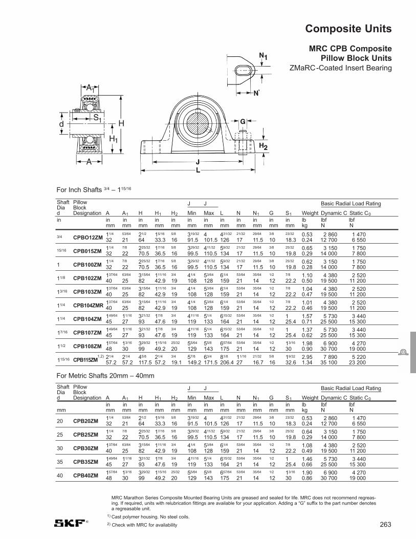
Shaft Pillow J J Basic Radial Load RatingDia Blockd Designation A A1 H H1 H2 Min Max L N N1 G S1 Weight Dynamic C Static C0
in in in in in in in in in in in in in lb lbf lbf mm mm mm mm mm mm mm mm mm mm mm mm kg N N
263
Shaft Pillow J J Basic Radial Load RatingDia Blockd Designation A A1 H H1 H2 Min Max L N N1 G S1 Weight Dynamic C Static C0
in in in in in in in in in in in in lb lbf lbf mm mm mm mm mm mm mm mm mm mm mm mm mm kg N N
20 CPB20ZM 11/4 53/64 21/2 15/16 5/8 319/32 4 431/32 21/32 29/64 3/8 23/32 0.53 2 860 1 47032 21 64 33.3 16 91.5 101.5 126 17 11.5 10 18.3 0.24 12 700 6 550
25 CPB25ZM 11/4 7/8 225/32 17/16 5/8 329/32 411/32 59/32 21/32 29/64 3/8 25/32 0.64 3 150 1 75032 22 70.5 36.5 16 99.5 110.5 134 17 11.5 10 19.8 0.29 14 000 7 800
30 CPB30ZM 137/64 63/64 315/64 111/16 3/4 41/4 53/64 61/4 53/64 35/64 1/2 7/8 1.08 4 380 2 52040 25 82 42.9 19 108 128 159 21 14 12 22.2 0.49 19 500 11 200
35 CPB35ZM 149/64 11/16 331/32 17/8 3/4 411/16 51/4 615/32 53/64 35/64 1/2 1 1.46 5 730 3 44045 27 93 47.6 19 119 133 164 21 14 12 25.4 0.66 25 500 15 300
40 CPB40ZM 157/64 13/16 329/32 115/16 25/32 55/64 55/8 657/64 53/64 35/64 1/2 13/16 1.90 6 900 4 27048 30 99 49.2 20 129 143 175 21 14 12 30 0.86 30 700 19 000
MRC Marathon Series Composite Mounted Bearing Units are greased and sealed for life. MRC does not recommend regreas-ing. If required, units with relubrication fittings are available for your application. Adding a “G” suffix to the part number denotesa regreasable unit.
1) Cast polymer housing. No steel coils.
2) Check with MRC for availability
Composite Units
MRC CPB CompositePillow Block Units
ZMaRC-Coated Insert Bearing
3/4 CPBO12ZM11/4 53/64 21/2 15/16 5/8 319/32 4 431/32 21/32 29/64 3/8 23/32 0.53 2 860 1 47032 21 64 33.3 16 91.5 101.5 126 17 11.5 10 18.3 0.24 12 700 6 550
15/16 CPB015ZM11/4 7/8 225/32 17/16 5/8 329/32 411/32 59/32 21/32 29/64 3/8 25/32 0.65 3 150 1 75032 22 70.5 36.5 16 99.5 110.5 134 17 11.5 10 19.8 0.29 14 000 7 800
1 CPB100ZM11/4 7/8 225/32 17/16 5/8 329/32 411/32 59/32 21/32 29/64 3/8 25/32 0.62 3 150 1 75032 22 70.5 36.5 16 99.5 110.5 134 17 11.5 10 19.8 0.28 14 000 7 800
11/8 CPB102ZM 137/64 63/64 315/64 111/16 3/4 41/4 53/64 61/4 53/64 35/64 1/2 7/8 1.10 4 380 2 52040 25 82 42.9 19 108 128 159 21 14 12 22.2 0.50 19 500 11 200
13/16 CPB103ZM 137/64 63/64 315/64 111/16 3/4 41/4 53/64 61/4 53/64 35/64 1/2 7/8 1.04 4 380 2 52040 25 82 42.9 19 108 128 159 21 14 12 22.2 0.47 19 500 11 200
11/4 CPB104ZMR 137/64 63/64 315/64 111/16 3/4 41/4 53/64 61/4 53/64 35/64 1/2 7/8 1.01 4 380 2 520 40 25 82 42.9 19 108 128 159 21 14 12 22.2 0.46 19 500 11 200
11/4 CPB104ZM 149/64 11/16 321/32 17/8 3/4 411/16 51/4 615/32 53/64 35/64 1/2 1 1.57 5 730 3 44045 27 93 47.6 19 119 133 164 21 14 12 25.4 0.71 25 500 15 300
17/16 CPB107ZM 149/64 11/16 321/32 17/8 3/4 411/16 51/4 615/32 53/64 35/64 1/2 1 1.37 5 730 3 44045 27 93 47.6 19 119 133 164 21 14 12 25.4 0.62 25 500 15 300
11/2 CPB108ZM 157/64 13/16 329/32 115/16 25/32 55/64 55/8 657/64 53/64 35/64 1/2 13/16 1.98 6 900 4 27048 30 99 49.2 20 129 143 175 21 14 12 30 0.90 30 700 19 000
115/16 CPB115ZM1,2) 21/4 21/4 45/8 21/4 3/4 57/8 63/4 81/8 11/16 21/32 5/8 19/32 2.95 7 890 5 220
57.2 57.2 117.5 57.2 19.1 149.2 171.5 206.4 27 16.7 16 32.6 1.34 35 100 23 200
For Metric Shafts 20mm – 40mm
For Inch Shafts 3/4 – 115/16

Shaft Pillow J J Basic Radial Load RatingDia Blockd Designation A A1 H H1 H2 Min Max L N N1 G S1 Weight Dynamic C Static C0
in in in in in in in in in in in in in lb lbf lbf mm mm mm mm mm mm mm mm mm mm mm mm kg N N
Shaft Pillow J J Basic Radial Load RatingDia Blockd Designation A A1 H H1 H2 Min Max L N N1 G S1 Weight Dynamic C Static C0
mm in in in in in in in in in in in in lb lbf lbf mm mm mm mm mm mm mm mm mm mm mm mm kg N N
264
20 CPB20SS 11/4 53/64 21/2 15/16 5/8 319/32 4 431/32 21/32 29/64 3/8 23/32 0.53 2 380 1 47032 21 64 33.3 16 91.5 101.5 126 17 11.5 10 18.3 0.24 10 600 6 550
25 CPB25SS 11/4 7/8 225/32 17/16 5/8 329/32 411/32 59/32 21/32 29/64 3/8 25/32 0.64 2 520 1 75032 22 70.5 36.5 16 99.5 110.5 134 17 11.5 10 19.8 0.29 11 200 7 800
30 CPB30SS 137/64 63/64 315/64 111/16 3/4 41/4 53/64 61/4 53/64 35/64 1/2 7/8 1.08 3 510 2 52040 25 82 42.9 19 108 128 159 21 14 12 22.2 0.49 15 600 11 200
35 CPB35SS 149/64 11/16 321/32 17/8 3/4 411/16 51/4 615/32 53/64 35/64 1/2 1 1.46 4 560 3 44045 27 93 47.6 19 119 133 164 21 14 12 25.4 0.66 20 300 15 300
40 CPB40SS 157/64 13/16 329/32 115/16 25/32 55/64 55/8 657/64 53/64 35/64 1/2 13/16 1.90 5 550 4 27048 30 99 49.2 20 129 143 175 21 14 12 30 0.86 24 700 19 000
3/4 CPB012SS 11/4 53/64 21/2 15/16 5/8 319/32 4 431/32 21/32 29/64 3/8 23/32 0.53 2 380 1 47032 21 64 33.3 16 91.5 101.5 126 17 11.5 10 18.3 0.24 10 600 6 550
1 CPB100SS 11/4 7/8 225/32 17/16 5/8 329/32 411/32 59/32 21/32 29/64 3/8 25/32 0.62 2 520 1 75032 22 70.5 36.5 16 99.5 110.5 134 17 11.5 10 19.8 0.28 11 200 7 800
13/16 CPB103SS 137/64 63/64 315/64 111/16 3/4 41/4 53/64 61/4 53/64 35/64 1/2 7/8 1.04 3 510 2 52040 25 82 42.9 19 108 128 159 21 14 12 22.2 0.47 15 600 11 200
11/4 CPB104SSR 137/64 63/64 315/64 111/16 3/4 41/4 53/64 61/4 53/64 35/64 1/2 7/8 1.04 3 510 2 52040 25 82 42.9 19 108 128 159 21 14 12 22.2 0.47 15 600 11 200
11/4 CPB104SS 149/64 11/16 321/32 17/8 3/4 411/16 51/4 615/32 53/64 35/64 1/2 1 1.57 4 560 3 44045 27 93 47.6 19 119 133 164 21 14 12 25.4 0.71 20 300 15 300
13/8 CPB106SS 149/64 11/16 321/32 17/8 3/4 411/16 51/4 615/32 53/64 35/64 1/2 1 1.44 4 560 3 44045 27 93 47.6 19 119 133 164 21 14 12 25.4 0.65 20 300 15 300
17/16 CPB107SS 149/64 11/16 321/32 17/8 3/4 411/16 51/4 615/32 53/64 35/64 1/2 1 1.37 4 560 3 44045 27 93 47.6 19 119 133 164 21 14 12 25.4 0.62 20 300 15 300
11/2 CPB108SS157/64 13/16 329/32 115/16 25/32 55/64 55/8 657/64 53/64 35/64 1/2 13/16 1.98 5 550 4 27048 30 99 49.2 20 129 143 175 21 14 12 30 0.90 24 700 19 000
For Metric Shafts 20mm – 40mm
For Inch Shafts 3/4 – 11/2
Visit www.mrcbearingservices.com to download CAD drawings of MRC bearings
CPB CompositePillow Block UnitsStainless Steel Insert Bearing
MRC Marathon Series Composite Mounted Bearing Units are greased and sealed for life. MRC does not recommend regreasing. If required, unitswith relubrication fittings are available for your application. Adding a “G” suffix to the part number denotes a regreasable unit.

Shaft Flange Basic Radial Load RatingDia Unitd Designation A1 A2 Da H J L N G T Weight Dynamic C Static C0
in in in in in in in in in in lb lbf lbf mm mm mm mm mm mm mm mm mm kg N N
Shaft Flange Basic Radial Load RatingDia Unitd Designation A1 A2 Da H J L N G T Weight Dynamic C Static C0
in in in in in in in in in lb lbf lbfmm mm mm mm mm mm mm mm mm mm kg N N
265
20 C2F20ZM 15/32 19/32 2 413/32 317/32 23/8 29/64 3/8 115/32 0.53 2 860 1 47029.5 15 50.8 112 90 60.5 11.5 10 37.3 0.24 12 700 6 550
25 C2F25ZM 13/16 19/32 21/2 47/8 329/32 23/4 29/64 3/8 117/32 0.64 3 150 1 75030 15 63.5 124 99 70 11.5 10 38.8 0.29 14 000 7 800
30 C2F30ZM 19/32 19/32 3 539/64 419/32 317/64 29/64 3/8 121/32 0.97 4 380 2 52033 15 76.2 142.5 116.5 83 11.5 10 42.2 0.44 19 500 11 200
35 C2F35ZM 13/8 21/32 31/2 61/8 51/8 325/32 35/64 1/2 153/64 1.35 5 730 3 44035 17 88.9 156 130 96 14 12 46.4 0.61 25 500 15 300
40 C2F40ZM1) 11/4 9/16 31/2 625/32 521/32 49/16 17/32 1/2 21/32 1.90 6 900 4 270
31.8 14.3 88.9 172.2 143.7 115.9 13.5 12 51.7 0.86 30 700 19 000
C2F Composite Two-Bolt Flange Units
ZMaRC-Coated Insert Bearing
3/4 C2F012ZM 15/32 19/32 2 413/32 317/32 23/8 29/64 3/8 115/32 0.53 2 860 1 47029.5 15 50.8 112 90 60.5 11.5 10 37.3 0.24 12 700 6 550
15/16 C2F015ZM 13/16 19/32 21/2 47/8 329/32 23/4 29/64 3/8 117/32 0.67 3 150 1 75030 15 63.5 124 99 70 11.5 10 38.8 0.30 14 000 7 800
1 C2F100ZM 13/16 19/32 21/2 47/8 329/32 23/4 29/64 3/8 117/32 0.62 3 150 1 75030 15 63.5 124 99 70 11.5 10 38.8 0.28 14 000 7 800
11/8 C2F102ZM 19/32 19/32 3 539/64 419/32 317/64 29/64 3/8 121/32 0.99 4 380 2 52033 15 76.2 142.5 116.5 83 11.5 10 42.2 0.45 19 500 11 200
13/16 C2F103ZM 19/32 19/32 3 539/64 419/32 317/64 29/64 3/8 121/32 0.93 4 380 2 52033 15 76.2 142.5 116.5 83 11.5 10 42.2 0.42 19 500 11 200
11/4 C2F104ZMR 19/32 19/32 3 539/64 419/32 317/64 29/64 3/8 121/32 0.88 4 380 2 52033 15 76.2 142.5 116.5 83 11.5 10 42.2 0.40 19 500 11 200
11/4 C2F104ZM 13/8 21/32 31/2 61/8 51/8 325/32 35/64 1/2 153/64 1.46 5 730 3 44035 17 88.9 156 130 96 14 12 46.4 0.66 25 500 15 300
17/16 C2F107ZM 13/8 21/32 31/2 61/8 51/8 325/32 35/64 1/2 153/64 1.28 5 730 3 44035 17 88.9 156 130 96 14 12 46.4 0.58 25 500 15 300
11/2 C2F108ZM1) 11/4 9/16 31/2 625/32 521/32 49/16 17/32 1/2 21/32 1.90 6 900 4 270
31.8 14.3 88.9 172.2 143.7 115.9 13.5 12 51.66 0.86 30 700 19 000
115/16 C2F115ZM1,2) 11/4 5/8 4 75/16 63/16 51/16 17/32 1/2 21/8 2.25 7 890 5 220
31.8 15.9 101.6 185.7 157.2 128.6 13.5 12 54 1.02 35 100 23 200
MRC Marathon Series Composite Mounted Bearing Units are greased and sealed for life. MRC does not recommendregreasing. If required, units with relubrication fittings are available for your application. Adding a “G” suffix to the part num-ber denotes a regreasable unit.
1) Cast polymer housing, no steel coils.
2) Check with MRC for availability
For Metric Shafts 20mm – 40mm
For Inch Shafts 3/4 – 115/16

Shaft Flange Basic Radial Load RatingDia Unitd Designation A1 A2 Da H J L N G T Weight Dynamic C Static C0
in in in in in in in in in in lb lbf lbfmm mm mm mm mm mm mm mm mm kg N N
3/4 C2F012SS 15/32 19/32 2 413/32 317/32 23/8 29/64 3/8 115/32 0.53 2 380 1 47029.5 15 50.8 112 90 60.5 11.5 10 37.3 0.24 10 600 6 550
1 C2F100SS 13/16 19/32 21/2 47/8 329/32 23/4 29/64 3/8 117/32 0.62 2 520 1 75030 15 63.5 124 99 70 11.5 10 38.8 0.28 11 200 7 800
13/16 C2F103SS 19/32 19/32 3 539/64 419/32 317/64 29/64 3/8 121/32 0.93 3 510 2 52033 15 76.2 142.5 116.5 83 11.5 10 42.2 0.42 15 600 11 200
11/4 C2F104SSR 19/32 19/32 3 539/64 419/32 317/64 29/64 3/8 121/32 0.93 3 510 2 52033 15 76.2 142.5 116.5 83 11.5 10 42.2 0.42 15 600 11 200
11/4 C2F104SS 13/8 21/32 31/2 61/8 51/8 325/32 35/64 1/2 153/64 1.46 4 560 3 44035 17 88.9 156 130 96 14 12 46.4 0.66 20 300 15 300
13/8 C2F106SS 13/8 21/32 31/2 61/8 51/8 325/32 35/64 1/2 153/64 1.35 4 560 3 44035 17 88.9 156 130 96 14 12 46.4 0.61 20 300 15 300
17/16 C2F107SS 13/8 21/32 31/2 61/8 51/8 325/32 35/64 1/2 153/64 1.28 4 560 3 44035 17 88.9 156 130 96 14 12 46.4 0.58 20 300 15 300
11/2 C2F108SS1) 11/4 9/16 31/2 625/32 521/32 49/16 17/32 1/2 21/32 1.90 5 550 4 270
31.8 14.3 88.9 172.2 143.7 115.9 13.5 12 51.7 0.86 24 700 19 000
266Visit www.mrcbearingservices.com to download CAD drawings of MRC bearings
Shaft Flange Basic Radial Load RatingDia Unitd Designation A1 A2 Da H J L N G T Weight Dynamic C Static C0
in in in in in in in in in lb lbf lbfmm mm mm mm mm mm mm mm mm mm kg N N
20 C2F20SS 15/32 19/32 2 413/32 317/32 23/8 29/64 3/8 115/32 0.53 2 380 1 47029.5 15 50.8 112 90 60.5 11.5 10 37.3 0.24 10 600 6 550
25 C2F25SS 13/16 19/32 21/2 47/8 329/32 23/4 29/64 3/8 117/32 0.64 2 520 1 75030 15 63.5 124 99 70 11.5 10 38.8 0.29 11 200 7 800
30 C2F30SS 19/32 19/32 3 539/64 419/32 317/64 29/64 3/8 121/32 0.97 3 510 2 52033 15 76.2 142.5 116.5 83 11.5 10 42.2 0.44 15 600 11 200
35 C2F35SS 13/8 21/32 31/2 61/8 51/8 325/32 35/64 1/2 153/64 1.35 4 560 3 44035 17 88.9 156 130 96 14 12 46.4 0.61 20 300 15 300
40 C2F40SS1) 11/4 9/16 31/2 625/32 521/32 49/16 17/32 1/2 21/32 1.90 5 550 4 270
31.8 14.3 88.9 172.2 143.7 115.9 13.5 12 51.7 0.86 24 700 19 000
MRC Marathon Series Composite Mounted Bearing Units are greased and sealed for life. MRC does not recommend regreasing. If required,units with relubrication fittings are available for your application. Adding a “G” suffix to the part number denotes a regreasable unit.
1)Cast polymer housing, no steel coils.
C2F Composite Two-Bolt Flange UnitsStainless Steel Insert Bearing
For Metric Shafts 20mm – 40mm
For Inch Shafts 3/4 – 11/2

Shaft Flange Basic Radial Load RatingDia Unitd Designation A1 A2 Da J L N G T Weight Dynamic C Static C0
in in in in in in in in in lb lbf lbfmm mm mm mm mm mm mm mm kg N N
3/4 C4F012ZM 13/16 19/32 211/16 21/2 33/8 29/64 3/8 115/32 0.57 2 860 1 47030 15 68.5 63.5 86 11.5 10 37.3 0.26 12 700 6 550
15/16 C4F015ZM 17/32 19/32 215/16 23/4 33/4 29/64 3/8 117/32 0.76 3 150 1 75031 15 74.6 70 95 11.5 10 38.8 0.34 14 000 7 800
1 C4F100ZM 17/32 19/32 215/16 23/4 33/4 29/64 3/8 117/32 0.71 3 150 1 75031 15 74.6 70 95 11.5 10 38.8 0.32 14 000 7 800
11/8 C4F102ZM 19/32 19/32 311/16 31/4 41/4 29/64 3/8 121/32 1.07 4 380 2 52033 15 93.7 82.5 108 11.5 10 42.2 0.49 19 500 11 200
13/16 C4F103ZM 19/32 19/32 311/16 31/4 41/4 29/64 3/8 121/32 1.01 4 380 2 52033 15 93.7 82.5 108 11.5 10 42.2 0.46 19 500 11 200
11/4 C4F104ZMR 19/32 19/32 311/16 31/4 41/4 29/64 3/8 121/32 0.97 4 380 2 52033 15 93.7 82.5 108 11.5 10 42.2 0.44 19 500 11 200
11/4 C4F104ZM 13/8 21/32 43/16 35/8 45/8 35/64 1/2 153/64 1.57 5 730 3 44035 17 106.4 92 118 14 12 46.4 0.71 25 500 15 300
17/16 C4F107ZM 13/8 21/32 43/16 35/8 45/8 35/64 1/2 153/64 1.37 5 730 3 44035 17 106.4 92 118 14 12 46.4 0.62 25 500 15 300
11/2 C4F108ZM 117/32 21/32 49/16 4 51/8 35/64 1/2 29/64 1.98 6 900 4 27039 17 115.9 101.5 130 14 12 54.2 0.90 30 700 19 000
115/16 C4F115ZM1,2) 11/4 5/8 415/16 43/8 51/2 35/64 1/2 21/8 2.45 7 890 5 220
31.8 15.9 125.4 111.1 139.7 14 12 54.0 1.21 35 100 23 200
Shaft Flange Basic Radial Load RatingDia Unitd Designation A1 A2 Da J L N G T Weight Dynamic C Static C0
in in in in in in in in lb lbf lbfmm mm mm mm mm mm mm mm mm kg N N
267
20 C4F20ZM 13/16 19/32 211/16 21/2 33/8 29/64 3/8 115/32 0.57 2 860 1 47030 15 68.5 63.5 86 11.5 10 37.3 0.26 12 700 6 550
25 C4F25ZM 17/32 19/32 215/16 23/4 33/4 29/64 3/8 117/32 0.73 3 150 1 75031 15 74.6 70 95 11.5 10 38.8 0.33 14 000 7 800
30 C4F30ZM 19/32 19/32 311/16 31/4 41/4 29/64 3/8 121/32 1.06 4 380 2 52033 15 93.7 82.5 108 11.5 10 42.2 0.48 19 500 11 200
35 C4F35ZM 13/8 21/32 43/16 35/8 45/8 35/64 1/2 153/64 1.46 5 730 3 44035 17 106.4 92 118 14 12 46.4 0.66 25 500 15 300
40 C4F40ZM 117/32 21/32 49/16 4 51/8 35/64 1/2 29/64 1.92 6 900 4 27039 17 115.9 101.5 130 14 12 54.2 0.87 30 700 19 000
C4F Composite Four-Bolt Flange Units
ZMaRC-Coated Insert Bearing
MRC Marathon Series Composite Mounted Bearing Units are greased and sealed for life. MRC does not recommend regreasing. If required, unitswith relubrication fittings are available for your application. Adding a “G” suffix to the part number denotes a regreasable unit.
1) Cast polymer housing. No steel coil
2) Check with MRC for availability
For Metric Shafts 20mm – 40mm
For Inch Shafts 3/4 – 115/16

268Visit www.mrcbearingservices.com to download CAD drawings of MRC bearings
C4F Composite Four-Bolt Flange UnitsStainless Steel Insert Bearing
Shaft Flange Basic Radial Load RatingDia Unitd Designation A1 A2 Da J L N G T Weight Dynamic C Static C0
in in in in in in in in in lb lbf lbfmm mm mm mm mm mm mm mm kg N N
3/4 C4F012SS 13/16 19/32 211/16 21/2 33/8 29/64 3/8 115/32 0.57 2 380 1 47030 15 68.3 63.5 86 11.5 10 37.3 0.26 10 600 6 550
1 C4F100SS 17/32 19/32 215/16 23/4 33/4 29/64 3/8 117/32 0.71 2 520 1 75031 15 74.6 70 95 11.5 10 38.8 0.32 11 200 7 800
13/16 C4F103SS 19/32 19/32 311/16 31/4 41/4 29/64 3/8 121/32 1.01 3 510 2 52033 15 93.7 82.5 108 11.5 10 42.2 0.46 15 600 11 200
11/4 C4F104SSR 11/16 1/2 311/16 31/4 41/4 15/32 7/16 143/64 1.40 4 560 3 44027 12.7 93.7 82.5 108 11.9 11.1 42.5 0.63 20 300 15 300
11/4 C4F104SS 13/8 21/32 43/16 35/8 45/8 35/64 1/2 153/64 1.57 4 560 3 44035 17 106.4 92 118 14 12 46.4 0.71 20 300 15 300
13/8 C4F106SS 13/8 21/32 43/16 35/8 45/8 35/64 1/2 153/64 1.46 4 560 3 44035 17 106.4 92 118 14 12 46.4 0.66 20 300 15 300
17/16 C4F107SS 13/8 21/32 43/16 35/8 45/8 35/64 1/2 153/64 1.37 4 560 3 44035 17 106.4 92 118 14 12 46.4 0.62 20 300 15 300
11/2 C4F108SS 117/32 21/32 49/16 4 51/8 35/64 1/2 29/64 1.98 5 550 4 27039 17 115.9 101.5 130 14 12 54.2 0.90 24 700 19 000
MRC Marathon Series Composite Mounted Bearing Units are greased and sealed for life. MRC does not recommend regreasing. If required, units with relubrication fittings are available for your application. Adding a “G” suffix to the part number denotes a regreasable unit.
For Metric Shafts 20mm – 40mm
For Inch Shafts 3/4 – 11/2
Shaft Flange Basic Radial Load RatingDia Unitd Designation A1 A2 Da J L N G T Weight Dynamic C Static C0
in in in in in in in in lb lbf lbfmm mm mm mm mm mm mm mm mm kg N
20 C4F20SS 13/16 19/32 211/16 21/2 33/8 29/64 3/8 115/32 0.57 2 380 1 47030 15 68.3 63.5 86 11.5 10 37.3 0.26 10 600 6 550
25 C4F25SS 17/32 19/32 215/16 23/4 33/4 29/64 3/8 117/32 0.73 2 520 1 75031 15 74.6 70 95 11.5 10 38.8 0.33 11 200 7 800
30 C4F30SS 19/32 19/32 311/16 31/4 41/4 29/64 3/8 121/32 1.06 3 510 2 52033 15 93.7 82.5 108 11.5 10 42.2 0.48 15 600 11 200
35 C4F35SS 13/8 21/32 43/16 35/8 45/8 35/64 1/2 153/64 1.46 4 560 3 44035 17 106.4 92 118 14 12 46.4 0.66 20 300 15 300
40 C4F40SS 117/32 21/32 49/16 4 51/8 35/64 1/2 29/64 1.92 5 550 4 27039 17 115.9 101.5 130 14 12 54.2 0.87 24 700 19 000

20 CTB20ZM 17/16 25/8 15/16 2 3 1/23/8 –16
23/32 0.51 2 860 1 47036.5 66.7 33.3 50.8 76.2 12.7 18.3 0.23 12 700 6 550
25 CTB25ZM 17/16 215/16 17/16 2 31/4 1/23/8 –16
25/32 0.67 3 150 1 75036.5 74.6 36.5 50.8 82.5 12.7 19.8 0.30 14 000 7 800
30 CTB30ZM 15/8 33/8 111/16 3 41/4 5/87/16 –14
7/8 1.00 4 380 2 52041.3 85.7 42.9 76.2 108.0 15.9 22.2 0.45 19 500 11 200
35 CTB35ZM 13/4 37/8 17/8 31/4 41/2 3/41/2 –13
1 1.60 5 730 3 44044.5 98.4 47.6 82.6 114.3 19.1 25.4 0.73 25 500 15 300
40 CTB40ZM 17/8 41/8 115/16 31/2 43/4 3/41/2 –13
13/16 2.00 6 900 4 27047.6 104.8 49.2 88.9 120.7 19.1 30 0.91 30 700 19 000
Shaft Tapped-Base Basic Radial Load RatingDia Unitd Designation A H H1 J L F G S1 Weight Dynamic C Static C0
in in in in in in UNC in lb lbf lbf mm mm mm mm mm mm mm threads mm kg N N
269
CTBComposite Tapped-Base Units
ZMaRC-Coated Insert Bearing
Shaft Tapped-Base Basic Radial Load RatingDia Unitd Designation A H H1 J L F G S1 Weight Dynamic C Static C0
in in in in in in in UNC in lb lbf lbf mm mm mm mm mm mm threads mm kg N N
3/4 CTB012ZM 17/16 25/8 15/16 2 3 1/23/8 –16
23/32 0.51 2 860 1 47036.5 66.7 33.3 50.8 76.2 12.7 18.3 0.23 12 700 6 550
15/16 CTB015ZM 17/16 215/16 17/16 2 31/4 1/23/8 –16
25/32 0.72 3 150 1 75036.5 74.6 36.5 50.8 82.5 12.7 19.8 0.32 14 000 7 800
1 CTB100ZM 17/16 215/16 17/16 2 31/4 1/23/8 –16
25/32 0.67 3 150 1 75036.5 74.6 36.5 50.8 82.5 12.7 19.8 0.30 14 000 7 800
11/8 CTB102ZM 15/8 33/8 111/16 3 41/4 5/87/16 –14
7/8 1.06 4 380 2 52041.3 85.7 42.9 76.2 108.0 15.9 22.2 0.48 19 500 11 200
13/16 CTB103ZM 15/8 33/8 111/16 3 41/4 5/87/16 –14
7/8 1.00 4 380 2 52041.3 85.7 42.9 76.2 108.0 15.9 22.2 0.45 19 500 11 200
11/4 CTB104ZMR 15/8 33/8 111/16 3 41/4 5/87/16 –14
7/8 1.00 4 380 2 52041.3 85.7 42.9 76.2 108.0 15.9 22.2 0.45 19 500 11 200
11/4 CTB104ZM 13/4 37/8 17/8 31/4 41/2 3/41/2 –13
1 1.60 5 730 3 44044.5 98.4 47.6 82.6 114.3 19.1 25.4 0.73 25 500 15 300
17/16 CTB107ZM 13/4 37/8 17/8 31/4 41/2 3/41/2 –13
1 1.60 5 730 3 44044.5 98.4 47.6 82.6 114.3 19.1 25.4 0.73 25 500 15 300
11/2 CTB108ZM 17/8 41/8 115/16 31/2 43/4 3/41/2 –13
13/16 2.00 6 900 4 27047.6 104.8 49.2 88.9 120.7 19.1 30 0.91 30 700 19 000
115/16 CTB115ZM 21/8 43/4 21/4 4 53/4 7/85/8 –11
19/32 2.65 7 890 5 22054 120.7 57.2 101.6 146.1 22.2 32.6 1.20 35 100 23 200
MRC Marathon Series Composite Mounted Bearing Units are greased and sealed for life. MRC does not recommend regreasing. If required, unitswith relubrication fittings are available for your application. Adding a “G” suffix to the part number denotes a regreasable unit
Cast polymer housing. No steel coils.
For Metric Shafts 20mm – 40mm
For Inch Shafts 3/4 – 115/16

270Visit www.mrcbearingservices.com to download CAD drawings of MRC bearings
CTBComposite Tapped-Base UnitsStainless Steel Insert Bearing
Shaft Tapped-Base Basic Radial Load RatingDia Unitd Designation A H H1 J L F G S1 Weight Dynamic C Static C0
in in in in in in in UNC in lb lbf lbf mm mm mm mm mm mm threads mm kg N N
3/4 CTB012SS 17/16 25/8 15/16 2 3 1/23/8 –16
23/32 0.51 2 380 1 47036.5 66.7 33.3 50.8 76.2 12.7 18.3 0.23 10 600 6 550
1 CTB100SS 17/16 215/16 17/16 2 31/4 1/23/8 –16
25/32 0.67 2 520 1 75036.5 74.6 36.5 50.8 82.5 12.7 19.8 0.30 11 200 7 800
13/16 CTB103SS 15/8 33/8 111/16 3 41/4 5/87/16 –14
7/8 1.00 3 500 2 52041.3 85.7 42.9 76.2 108.0 15.9 22.2 0.45 15 600 11 200
11/4 CTB104SSR 15/8 33/8 111/16 3 41/4 5/87/16 –14
1 1.30 4 560 3 44041.3 85.7 42.9 76.2 108.0 15.9 25.4 0.59 20 300 15 300
11/4 CTB104SS 13/4 37/8 17/8 31/4 41/2 3/41/2 –13
1 1.60 4 560 3 44044.5 98.4 47.6 82.6 114.3 19.1 25.4 0.73 20 300 15 300
13/8 CTB106SS 13/4 37/8 17/8 31/4 41/2 3/41/2 –13
1 1.60 4 560 3 44044.5 98.4 47.6 82.6 114.3 19.1 25.4 0.73 20 300 15 300
17/16 CTB107SS 13/4 37/8 17/8 31/4 41/2 3/41/2 –13
1 1.60 4 560 3 44044.5 98.4 47.6 82.6 114.3 19.1 25.4 0.73 20 300 15 300
11/2 CTB108SS 17/8 41/8 115/16 31/2 43/4 3/41/2 –13
13/16 2.00 5 550 4 27047.6 104.8 49.2 88.9 120.7 19.1 30 0.91 24 700 19 000
Shaft Tapped-Base Basic Radial Load RatingDia Unitd Designation A H H1 J L F G S1 Weight Dynamic C Static C0
in in in in in in UNC in lb lbf lbf mm mm mm mm mm mm mm threads mm kg N N
20 CTB20SS 17/16 25/8 15/16 2 3 1/23/8 –16
23/32 0.51 2 380 1 47036.5 66.7 33.3 50.8 76.2 12.7 18.3 0.23 10 600 6 550
25 CTB25SS 17/16 215/16 17/16 2 31/4 1/23/8 –16
25/32 0.67 2 520 1 75036.5 74.6 36.5 50.8 82.5 12.7 19.8 0.30 11 200 7 800
30 CTB30SS 15/8 33/8 111/16 3 41/4 5/87/16 –14
7/8 1.00 3 500 2 52041.3 85.7 42.9 76.2 108.0 15.9 22.2 0.45 15 600 11 200
35 CTB35SS 13/4 37/8 17/8 31/4 41/2 3/41/2 –13
1 1.60 4 560 3 44044.5 98.4 47.6 82.6 114.3 19.1 25.4 0.73 20 300 15 300
40 CTB40SS 17/8 41/8 115/16 31/2 43/4 3/41/2 –13
13/16 2.00 5 550 4 27047.6 104.8 49.2 88.9 120.7 19.1 30 0.91 24 700 19 000
MRC Marathon Series Composite Mounted Bearing Units are greased and sealed for life. MRC does not recommend regreasing. If required, units with relubricationfittings are available for your application. Adding a “G” suffix to the part number denotes a regreasable unit.
Cast polymer housing. No steel coils.
For Metric Shafts 20mm – 40mm
For Inch Shafts 3/4 – 11/2

271
CBF CompositeThree-Bolt Bracket Flange Units
ZMaRC-Coated Insert Bearing
Shaft Flange Basic Radial Load RatingDia Unit Boltd Designation A F B C L H J N G T Size Weight Dynamic C Static C0
in in in in in in in in in in in in lb lbf lbfmm mm mm mm mm mm mm mm mm mm kg N N
3/4 CBF012ZM15/16 7/16 411/32 111/16 29/16 7/8 11/2 11/32 13/32 15/16 3/8 0.51 2 860 1 47023.8 11.1 110.3 42.9 65.1 22.2 38.1 8.7 10.3 33.3 0.23 12 700 6 550
15/16 CBF015ZM2) 1 1/2 43/4 113/16 23/4 11/8 15/8 11/32 13/32 17/16 3/8 0.75 3 150 1 750
25.4 12.7 120.7 46.0 69.9 28.6 41.3 8.7 10.3 36.5 0.34 14 000 7 800
1 CBF100ZM 1 1/2 43/4 113/16 23/4 11/8 15/8 11/32 13/32 17/16 3/8 0.70 3 150 1 75025.4 12.7 120.7 46.0 69.9 28.6 41.3 8.7 10.3 36.5 0.32 14 000 7 800
11/8 CBF102ZM 11/16 1/2 57/16 21/16 31/4 11/4 17/8 25/64 13/32 135/64 3/8 1.10 4 380 2 52027.0 12.7 138.1 52.4 82.6 31.8 47.6 9.9 10.3 39.3 0.50 19 500 11 200
13/16 CBF103ZM 11/16 1/2 57/16 21/16 31/4 11/4 17/8 25/64 13/32 135/64 3/8 1.00 4 380 2 52027.0 12.7 138.1 52.4 82.6 31.8 47.6 9.9 10.3 39.3 0.45 19 500 11 200
11/4 CBF104ZMR 11/16 1/2 57/16 21/16 31/4 11/4 17/8 25/64 13/32 135/64 3/8 1.00 4 380 2 52027.0 12.7 138.1 52.4 82.6 31.8 47.6 9.9 10.3 39.3 0.45 19 500 11 200
11/4 CBF104ZM 17/32 9/16 63/16 23/8 313/16 11/4 2 13/32 17/32 113/16 1/2 1.50 5 730 3 44031.0 14.3 157.2 60.3 96.8 38.1 50.8 10.4 13.5 46.0 0.68 25 500 15 300
17/16 CBF107ZM 17/32 9/16 63/16 23/8 33/16 11/4 2 13/32 17/32 113/16 1/2 1.34 5 730 3 44031.0 14.3 157.2 60.3 96.8 31.8 50.8 10.4 13.5 46.0 0.61 25 500 15 300
11/2 CBF108ZM 11/4 9/16 611/16 29/16 41/4 13/8 21/4 13/32 17/32 21/64 1/2 1.90 6 900 4 27031.8 14.3 169.9 65.1 108.0 34.9 57.2 10.4 13.5 51.4 0.86 30 700 19 000
115/16 CBF115ZM2) 11/4 5/8 75/8 215/16 47/8 15/8 23/4 13/32 17/32 21/8 1/2 2.25 7 890 5 220
31.8 15.9 193.7 74.6 123.8 15.9 69.9 10.4 13.5 54.0 1.02 35 100 23 200
Shaft Flange Basic Radial Load RatingDia Unit Boltd Designation A F B C L H J N G T Size Weight Dynamic C Static C0
mm in in in in in in in in in in in lb lbf lbfmm mm mm mm mm mm mm mm mm mm kg N N
20 CBF20ZM15/16 7/16 411/32 111/16 29/16 7/8 11/2 11/32 13/32 15/16 3/8 0.51 2 860 1 47023.8 11.1 110.3 42.9 65.1 22.2 38.1 8.7 10.3 33.3 0.23 12 700 6 550
25 CBF25ZM 1 1/2 43/4 113/16 23/4 11/8 15/8 11/32 13/32 17/16 3/8 0.70 3 150 1 75025.4 12.7 120.7 46.0 69.9 28.6 41.3 8.7 10.3 36.5 0.32 14 000 7 800
30 CBF30ZM 11/16 1/2 57/16 21/16 31/4 11/4 17/8 25/64 13/32 135/64 3/8 1.00 4 380 2 52027.0 12.7 138.1 52.4 82.6 31.8 47.6 9.9 10.3 39.3 0.45 19 500 11 200
35 CBF35ZM 17/32 9/16 63/16 23/8 313/16 11/4 2 13/32 17/32 113/16 1/2 1.34 5 730 3 44031.0 14.3 157.2 60.3 96.8 31.8 50.8 10.4 13.5 46.0 0.61 25 500 15 300
40 CBF40ZM 11/4 9/16 611/16 29/16 41/4 13/8 21/4 13/32 17/32 21/64 1/2 1.90 6 900 4 27031.8 14.3 169.9 65.1 108.0 34.9 57.2 10.4 13.5 51.4 0.86 30 700 19 000
For Inch Shafts 3/4 – 115/16
For Metric Shafts 20mm – 40mm
MRC Marathon Series Composite Mounted Bearing Units are greased and sealed for life. MRC does not recommend regreasing. If required, units with relubrication fittings are available for your application. Adding a “G” suffix to the part number denotes a regreasable unit
Cast polymer housing. No steel coils.
2) Check with MRC for availability

272Visit www.mrcbearingservices.com to download CAD drawings of MRC bearings
CBF CompositeThree-Bolt Bracket Flange UnitsStainless Steel Insert Bearing
Shaft Flange Basic Radial Load RatingDia Unit Boltd Designation A F B C L H J N G T Size Weight Dynamic C Static C0
in in in in in in in in in in in in lb lbf lbfmm mm mm mm mm mm mm mm mm mm kg N N
3/4 CBF012SS15/16 7/16 411/32 111/16 29/16 7/8 11/2 11/32 13/32 15/16 3/8 0.51 2 380 1 47023.8 11.1 110.3 42.9 65.1 22.2 38.1 8.7 10.3 33.3 0.23 10 600 6 550
1 CBF100SS 1 1/2 43/4 113/16 23/4 11/8 15/8 11/32 13/32 17/16 3/8 0.70 2 520 1 75025.4 12.7 120.7 46.0 69.9 28.6 41.3 8.7 10.3 36.5 0.32 11 200 7 800
13/16 CBF103SS 11/16 1/2 57/16 21/16 31/4 11/4 17/8 25/64 13/32 135/64 3/8 1.00 3 510 2 52027.0 12.7 138.1 52.4 82.6 31.8 47.6 9.9 10.3 39.3 0.45 15 600 11 200
11/4 CBF104SSR 11/16 1/2 57/16 21/16 31/4 11/4 17/8 25/64 13/32 143/64 3/8 1.30 4 560 3 44027.0 12.7 138.1 52.4 82.6 31.8 47.6 9.9 10.3 42.5 0.59 20 300 15 300
11/4 CBF104SS 17/32 9/16 63/16 23/8 313/16 11/4 2 13/32 17/32 113/16 1/2 1.50 4 560 3 44031.0 14.3 157.2 60.3 96.8 31.8 50.8 10.4 13.5 46.0 0.68 20 300 15 300
13/8 CBF106SS 17/32 9/16 63/16 23/8 313/16 11/4 2 13/32 17/32 113/16 1/2 1.40 4 560 3 44031.0 14.3 157.2 60.3 96.8 31.8 50.8 10.4 13.5 46.0 0.63 20 300 15 300
17/16 CBF107SS 17/32 9/16 63/16 23/8 313/16 11/4 2 13/32 17/32 113/16 1/2 1.34 4 560 3 44031.0 14.3 157.2 60.3 96.8 31.8 50.8 10.4 13.5 46.0 0.61 20 300 15 300
11/2 CBF108SS 11/4 9/16 611/16 29/16 41/4 13/8 21/4 13/32 17/32 21/64 1/2 1.90 5 550 4 27031.8 14.3 169.9 65.1 108.0 34.9 57.2 10.4 13.5 51.4 0.86 24 700 19 000
Shaft Flange Basic Radial Load RatingDia Unit Boltd Designation A F B C L H J N G T Size Weight Dynamic C Static C0
mm in in in in in in in in in in in lb lbf lbfmm mm mm mm mm mm mm mm mm mm kg N N
20 CBF20SS15/16 7/16 411/32 111/16 29/16 7/8 11/2 11/32 13/32 15/16 3/8 0.51 2 380 1 47023.8 11.1 110.3 42.9 65.1 22.2 38.1 8.7 10.3 33.3 0.23 10 600 6 550
25 CBF25SS 1 1/2 43/4 113/16 23/4 11/8 15/8 11/32 13/32 17/16 3/8 0.70 2 520 1 75025.4 12.7 120.7 46.0 69.9 28.6 41.3 8.7 10.3 36.5 0.32 11 200 7 800
30 CBF30SS 11/16 1/2 57/16 21/16 31/4 11/4 17/8 25/64 13/32 135/64 3/8 1.00 3 510 2 52027.0 12.7 138.1 52.4 82.6 31.8 47.6 9.9 10.3 39.3 0.45 15 600 11 200
35 CBF35SS 17/32 9/16 63/16 23/8 313/16 11/4 2 13/32 17/32 113/16 1/2 1.34 4 560 3 44031.0 14.3 157.2 60.3 96.8 31.8 50.8 10.4 13.5 46.0 0.61 20 300 15 300
40 CBF40SS 11/4 9/16 611/16 29/16 41/4 13/8 21/4 13/32 17/32 21/64 1/2 1.90 5 550 4 27031.8 14.3 169.9 65.1 108.0 34.9 57.2 10.4 13.5 51.4 0.86 24 700 19 000
For Inch Shafts 3/4 – 11/2
For Metric Shafts 20mm – 40mm
MRC Marathon Series Composite Mounted Bearing Units are greased and sealed for life. MRC does not recommend regreasing. If required, units with relubrication fittings are available for your application. Adding a “G” suffix to the part number denotes a regreasable unit.
Cast polymer housing. No steel coils.

273
CTN CompositeNarrow Slot Take-Up UnitsZMaRC-Coated Insert Bearing
Shaft Take-Up PIN Basic Radial Load RatingDia Unit DIAd Designation A B C L D H G A1 J N S1 Weight Dynamic C Static C0
in in in in in in in in in in in in lb lbf lbfmm mm mm mm mm mm mm mm mm mm mm kg N N
3/4 CTN012ZM 13/8 31/8 25/8 37/16 23/16 7/8 7/16 1/4 5/16 25/32 23/32 0.70 2 860 1 470 34.9 79.4 66.7 87.3 55.5 22.2 11.1 6.4 7.9 19.8 18.3 0.32 12 700 6 550
15/16 CTN015ZM2) 13/8 31/8 25/8 39/16 23/16 7/8 7/16 1/4 5/16 25/32 25/32 0.75 3 150 1 750
34.9 79.4 66.7 90.5 55.5 22.2 11.1 6.4 7.9 19.8 19.8 0.34 14 000 7 800
1 CTN100ZM 13/8 31/8 25/8 39/16 23/16 7/8 7/16 1/4 5/16 25/32 25/32 0.70 3 150 1 750 34.9 79.4 66.7 90.5 55.5 22.2 11.1 6.4 7.9 19.8 19.8 0.32 14 000 7 800
11/8 CTN102ZM 13/8 41/8 31/2 45/16 211/16 1 1/2 1/4 5/16 25/32 7/8 1.20 4 380 2 52034.9 104.8 88.9 109.5 68.3 25.4 12.7 6.4 7.9 19.8 22.2 0.54 19 500 11 200
13/16 CTN103ZM 13/8 41/8 31/2 45/16 211/16 1 1/2 1/4 5/16 25/32 7/8 1.10 4 380 2 52034.9 104.8 88.9 109.5 68.3 25.4 12.7 6.4 7.9 19.8 22.2 0.50 19 500 11 200
11/4 CTN104ZMR 13/8 41/8 31/2 45/16 211/16 1 1/2 1/4 5/16 25/32 7/8 1.10 4 380 2 52034.9 104.8 88.9 109.5 68.3 25.4 12.7 6.4 7.9 19.8 22.2 0.50 19 500 11 200
11/4 CTN104ZM 13/8 41/8 31/2 41/2 211/16 1 1/2 1/4 5/16 25/32 1 1.60 5 730 3 44034.9 104.8 88.9 114.3 68.3 25.4 12.7 6.4 7.9 19.8 25.4 0.73 25 500 15 300
17/16 CTN107ZM 13/8 41/8 31/2 41/2 211/16 1 1/2 1/4 5/16 25/32 1 1.60 5 730 3 44034.9 104.8 88.9 114.3 68.3 25.4 12.7 6.4 7.9 19.8 25.4 0.73 25500 15 300
11/2 CTN108ZM 15/8 43/4 4 53/8 31/4 15/32 21/32 5/16 3/8 25/32 13/16 2.30 6 900 4 27041.3 120.7 101.6 136.5 82.6 29.4 16.7 7.9 9.5 19.8 30 1.00 30 700 19 000
115/16 CTN115ZM 15/8 43/4 4 51/2 31/4 15/32 21/32 5/16 3/8 29/32 19/32 2.55 7 890 5 22041.3 120.7 101.6 139.7 82.6 29.4 16.7 7.9 9.5 23.0 32.6 1.16 35 100 23 200
Shaft Take-Up PIN Basic Radial Load RatingDia Unit DIAd Designation A B C L D H G A1 J N S1 Weight Dynamic C Static C0
mm in in in in in in in in in in in lb lbf lbfmm mm mm mm mm mm mm mm mm mm mm kg N N
20 CTN20ZM 13/8 31/8 25/8 37/16 23/16 7/8 7/16 1/4 5/16 25/32 23/32 0.70 2 860 1 47034.9 79.4 66.7 87.3 55.5 22.2 11.1 6.4 7.9 19.8 18.3 0.32 12 700 6 550
25 CTN25ZM 13/8 31/8 25/8 39/16 23/16 7/8 7/16 1/4 5/16 25/32 25/32 0.70 3 150 1 75034.9 79.4 66.7 90.5 55.5 22.2 11.1 6.4 7.9 19.8 19.8 0.32 14 000 7 800
30 CTN30ZM 13/8 41/8 31/2 45/16 211/16 1 1/2 1/4 5/16 25/32 7/8 1.10 4 380 2 52034.9 104.8 88.9 109.5 68.3 25.4 12.7 6.4 7.9 19.8 22.2 0.50 19 500 11 200
35 CTN35ZM 13/8 41/8 31/2 41/2 211/16 1 1/2 1/4 5/16 25/32 1 1.60 5 730 3 44034.9 104.8 88.9 114.3 68.3 25.4 12.7 6.4 7.9 19.8 25.4 0.73 25 500 15 300
40 CTN40ZM 15/8 43/4 4 53/8 31/4 15/32 21/32 5/16 3/8 25/32 13/16 2.30 6 900 4 27041.3 120.7 101.6 136.5 82.6 29.4 16.7 7.9 9.5 19.8 30.0 1.00 30 700 19 000
For Inch Shafts 3/4 – 115/16
For Metric Shafts 20mm – 40mm
MRC Marathon Series Composite Mounted Bearing Units are greased and sealed for life. MRC does not recommend regreasing. If required, units with relubrication fittings are available for your application. Adding a “G” suffix to the part number denotes a regreasable unit.
Cast polymer housing. No steel coils.
2) Check with MRC for availability

274Visit www.mrcbearingservices.com to download CAD drawings of MRC bearings
CTN CompositeNarrow Slot Take-Up UnitsStainless Steel Insert Bearing
Shaft Take-Up PIN Basic Radial Load RatingDia Unit DIAd Designation A B C L D H G A1 J N S1 Weight Dynamic C Static C0
in in in in in in in in in in in in lb lbf lbfmm mm mm mm mm mm mm mm mm mm mm kg N N
3/4 CTN012SS 13/8 31/8 25/8 37/16 23/16 7/8 7/16 1/4 5/16 25/32 23/32 0.70 2 380 1 47034.9 79.4 66.7 87.3 55.5 22.2 11.1 6.4 7.9 19.8 18.3 0.32 10 600 6 550
1 CTN100SS 13/8 31/8 25/8 39/16 23/16 7/8 7/16 1/4 5/16 25/32 25/32 0.70 2 520 1 75034.9 79.4 66.7 90.5 55.5 22.2 11.1 6.4 7.9 19.8 19.8 0.32 11 200 7 800
13/16 CTN103SS 13/8 41/8 31/2 45/16 211/16 1 1/2 1/4 5/16 25/32 7/8 1.10 3 510 2 52034.9 104.8 88.9 109.5 68.3 25.4 12.7 6.4 7.9 19.8 22.2 0.50 15 600 11 200
11/4 CTN104SSR 13/8 41/8 31/2 45/16 211/16 1 1/2 1/4 5/16 25/32 1 1.40 4 560 3 44034.9 104.8 88.9 109.5 68.3 25.4 12.7 6.4 7.9 19.8 25.4 0.63 20 300 15 300
11/4 CTN104SS 13/8 41/8 31/2 41/2 211/16 1 1/2 1/4 5/16 25/32 7/8 1.60 4 560 3 44034.9 104.8 88.9 114.3 68.3 25.4 12.7 6.4 7.9 19.8 22.2 0.73 20 300 15 300
13/8 CTN106SS 13/8 41/8 31/2 41/2 211/16 1 1/2 1/4 5/16 25/32 1 1.60 4 560 3 44034.9 104.8 88.9 114.3 68.3 25.4 12.7 6.4 7.9 19.8 25.4 0.73 20 300 15 300
17/16 CTN107SS 13/8 41/8 31/2 41/2 211/16 1 1/2 1/4 5/16 25/32 1 1.60 4 560 3 44034.9 104.8 88.9 114.3 68.3 25.4 12.7 6.4 7.9 19.8 25.4 0.73 20 300 15 300
11/2 CTN108SS 15/8 43/4 4 53/8 31/4 15/32 21/32 5/16 3/8 25/32 13/16 2.30 5 550 4 27041.3 120.7 101.6 136.5 82.6 29.4 16.7 7.9 9.5 19.8 30.0 1.00 24 700 19 000
Shaft Take-Up PIN Basic Radial Load RatingDia Unit DIAd Designation A B C L D H G A1 J N S1 Weight Dynamic C Static C0
mm in in in in in in in in in in in lb lbf lbfmm mm mm mm mm mm mm mm mm mm mm kg N N
20 CTN20SS 13/8 31/8 25/8 37/16 23/16 7/8 7/16 1/4 5/16 25/32 23/32 0.70 2 380 1 47034.9 79.4 66.7 87.3 55.5 22.2 11.1 6.4 7.9 19.8 18.3 0.32 10 600 6 550
25 CTN25SS 13/8 31/8 25/8 39/16 23/16 7/8 7/16 1/4 5/16 25/32 25/32 0.70 2 520 1 75034.9 79.4 66.7 90.5 55.5 22.2 11.1 6.4 7.9 19.8 19.8 0.32 11 200 7 800
30 CTN30SS 13/8 41/8 31/2 45/16 211/16 1 1/2 1/4 5/16 25/32 7/8 1.10 3 510 2 52034.9 104.8 88.9 109.5 68.3 25.4 12.7 6.4 7.9 19.8 22.2 0.50 15 600 11 200
35 CTN35SS 13/8 41/8 31/2 41/2 211/16 1 1/2 1/4 5/16 25/32 1 1.60 4 560 3 44034.9 104.8 88.9 114.3 68.3 25.4 12.7 6.4 7.9 19.8 25.4 0.73 20 300 15 300
40 CTN40SS 15/8 43/4 4 53/8 31/4 15/32 21/32 5/16 3/8 25/32 13/16 2.30 5 550 4 27041.3 120.7 101.6 136.5 82.6 29.4 16.7 7.9 9.5 19.8 30.0 1.00 24 700 19 000
For Inch Shafts 3/4 – 11/2
For Metric Shafts 20mm – 40mm
MRC Marathon Series Composite Mounted Bearing Units are greased and sealed for life. MRC does not recommend regreasing. If required, units with relubrication fittings are available for your application. Adding a “G” suffix to the part number denotes a regreasable unit.
Cast polymer housing. No steel coils.
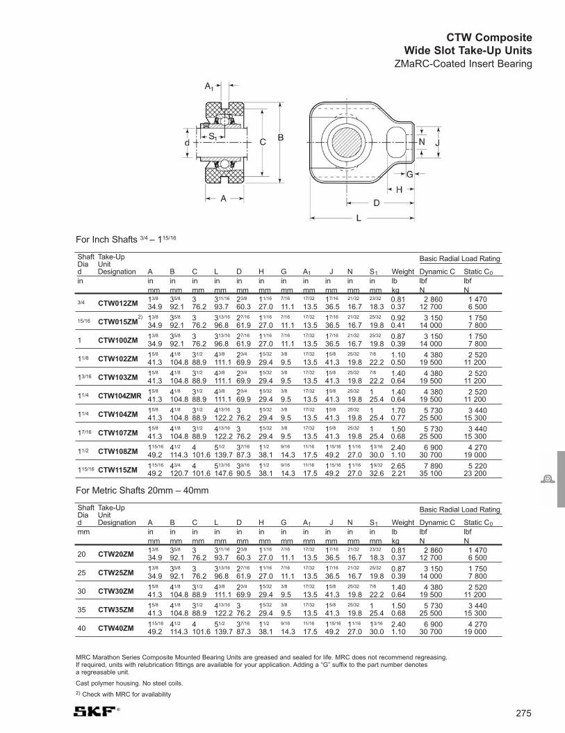
275
CTW CompositeWide Slot Take-Up Units
ZMaRC-Coated Insert Bearing
Shaft Take-Up Basic Radial Load RatingDia Unitd Designation A B C L D H G A1 J N S1 Weight Dynamic C Static C0
in in in in in in in in in in in in lb lbf lbfmm mm mm mm mm mm mm mm mm mm mm kg N N
3/4 CTW012ZM 13/8 35/8 3 311/16 23/8 11/16 7/16 17/32 17/16 21/32 23/32 0.81 2 860 1 470 34.9 92.1 76.2 93.7 60.3 27.0 11.1 13.5 36.5 16.7 18.3 0.37 12 700 6 500
15/16 CTW015ZM2) 13/8 35/8 3 313/16 27/16 11/16 7/16 17/32 17/16 21/32 25/32 0.92 3 150 1 750
34.9 92.1 76.2 96.8 61.9 27.0 11.1 13.5 36.5 16.7 19.8 0.41 14 000 7 800
1 CTW100ZM 13/8 35/8 3 313/16 27/16 11/16 7/16 17/32 17/16 21/32 25/32 0.87 3 150 1 750 34.9 92.1 76.2 96.8 61.9 27.0 11.1 13.5 36.5 16.7 19.8 0.39 14 000 7 800
11/8 CTW102ZM 15/8 41/8 31/2 43/8 23/4 15/32 3/8 17/32 15/8 25/32 7/8 1.10 4 380 2 52041.3 104.8 88.9 111.1 69.9 29.4 9.5 13.5 41.3 19.8 22.2 0.50 19 500 11 200
13/16 CTW103ZM 15/8 41/8 31/2 43/8 23/4 15/32 3/8 17/32 15/8 25/32 7/8 1.40 4 380 2 52041.3 104.8 88.9 111.1 69.9 29.4 9.5 13.5 41.3 19.8 22.2 0.64 19 500 11 200
11/4 CTW104ZMR 15/8 41/8 31/2 43/8 23/4 15/32 3/8 17/32 15/8 25/32 1 1.40 4 380 2 52041.3 104.8 88.9 111.1 69.9 29.4 9.5 13.5 41.3 19.8 25.4 0.64 19 500 11 200
11/4 CTW104ZM 15/8 41/8 31/2 413/16 3 15/32 3/8 17/32 15/8 25/32 1 1.70 5 730 3 44041.3 104.8 88.9 122.2 76.2 29.4 9.5 13.5 41.3 19.8 25.4 0.77 25 500 15 300
17/16 CTW107ZM 15/8 41/8 31/2 413/16 3 15/32 3/8 17/32 15/8 25/32 1 1.50 5 730 3 44041.3 104.8 88.9 122.2 76.2 29.4 9.5 13.5 41.3 19.8 25.4 0.68 25 500 15 300
11/2 CTW108ZM 115/16 41/2 4 51/2 37/16 11/2 9/16 11/16 115/16 11/16 13/16 2.40 6 900 4 27049.2 114.3 101.6 139.7 87.3 38.1 14.3 17.5 49.2 27.0 30.0 1.10 30 700 19 000
115/16 CTW115ZM 115/16 43/4 4 513/16 39/16 11/2 9/16 11/16 115/16 11/16 19/32 2.65 7 890 5 22049.2 120.7 101.6 147.6 90.5 38.1 14.3 17.5 49.2 27.0 32.6 2.21 35 100 23 200
Shaft Take-Up Basic Radial Load RatingDia Unitd Designation A B C L D H G A1 J N S1 Weight Dynamic C Static C0
mm in in in in in in in in in in in lb lbf lbfmm mm mm mm mm mm mm mm mm mm mm kg N N
20 CTW20ZM 13/8 35/8 3 311/16 23/8 11/16 7/16 17/32 17/16 21/32 23/32 0.81 2 860 1 47034.9 92.1 76.2 93.7 60.3 27.0 11.1 13.5 36.5 16.7 18.3 0.37 12 700 6 500
25 CTW25ZM 13/8 35/8 3 313/16 27/16 11/16 7/16 17/32 17/16 21/32 25/32 0.87 3 150 1 75034.9 92.1 76.2 96.8 61.9 27.0 11.1 13.5 36.5 16.7 19.8 0.39 14 000 7 800
30 CTW30ZM 15/8 41/8 31/2 43/8 23/4 15/32 3/8 17/32 15/8 25/32 7/8 1.40 4 380 2 52041.3 104.8 88.9 111.1 69.9 29.4 9.5 13.5 41.3 19.8 22.2 0.64 19 500 11 200
35 CTW35ZM 15/8 41/8 31/2 413/16 3 15/32 3/8 17/32 15/8 25/32 1 1.50 5 730 3 44041.3 104.8 88.9 122.2 76.2 29.4 9.5 13.5 41.3 19.8 25.4 0.68 25 500 15 300
40 CTW40ZM 115/16 41/2 4 51/2 37/16 11/2 9/16 11/16 115/16 11/16 13/16 2.40 6 900 4 27049.2 114.3 101.6 139.7 87.3 38.1 14.3 17.5 49.2 27.0 30.0 1.10 30 700 19 000
For Inch Shafts 3/4 – 115/16
For Metric Shafts 20mm – 40mm
MRC Marathon Series Composite Mounted Bearing Units are greased and sealed for life. MRC does not recommend regreasing. If required, units with relubrication fittings are available for your application. Adding a “G” suffix to the part number denotes a regreasable unit.
Cast polymer housing. No steel coils.
2) Check with MRC for availability

276Visit www.mrcbearingservices.com to download CAD drawings of MRC bearings
CTW CompositeWide Slot Take-Up UnitsStainless Steel Insert Bearing
Shaft Take-Up Basic Radial Load RatingDia Unitd Designation A B C L D H G A1 J N S1 Weight Dynamic C Static C0
in in in in in in in in in in in in lb lbf lbfmm mm mm mm mm mm mm mm mm mm mm kg N N
3/4 CTW012SS 13/8 35/8 3 311/16 23/8 11/16 7/16 17/32 17/16 21/32 23/32 0.81 2 380 1 470 34.9 92.1 76.2 93.7 60.3 27.0 11.1 13.5 36.5 16.7 18.3 0.37 10 600 6 500
1 CTW100SS 13/8 35/8 3 313/16 27/16 11/16 7/16 17/32 17/16 21/32 25/32 0.87 2 520 1 750 34.9 92.1 76.2 96.8 61.9 27.0 11.1 13.5 36.5 16.7 19.8 0.39 11 200 7 800
13/16 CTW103SS 15/8 41/8 31/2 43/8 23/4 15/32 3/8 17/32 15/8 25/32 7/8 1.40 3 510 2 25041.3 104.8 88.9 111.1 69.9 29.4 9.5 13.5 41.3 19.8 22.2 0.64 15 600 11 200
11/4 CTW104SSR 15/8 41/8 31/2 43/8 23/4 15/32 3/8 17/32 15/8 25/32 1 1.70 4 560 3 44041.3 104.8 88.9 111.1 69.9 29.4 9.5 13.5 41.3 19.8 25.4 0.77 20 300 15 300
11/4 CTW104SS 15/8 41/8 31/2 413/16 3 15/32 3/8 17/32 15/8 25/32 1 1.70 4 560 3 44041.3 104.8 88.9 122.2 76.2 29.4 9.5 13.5 41.3 19.8 25.4 0.77 20 300 15 300
13/8 CTW106SS 15/8 41/8 31/2 413/16 3 15/32 3/8 17/32 15/8 25/32 1 1.60 4 560 3 44041.3 104.8 88.9 122.2 76.2 29.4 9.5 13.5 41.3 19.8 25.4 0.73 20 300 15 300
17/16 CTW107SS 15/8 41/8 31/2 413/16 3 15/32 3/8 17/32 15/8 25/32 1 1.50 4 560 3 44041.3 104.8 88.9 122.2 76.2 29.4 9.5 13.5 41.3 19.8 25.4 0.68 20 300 15 300
11/2 CTW108SS 115/16 41/2 4 51/2 37/16 11/2 9/16 11/16 115/16 11/16 13/16 2.40 5 550 4 27049.2 114.3 101.6 139.7 87.3 38.1 14.3 17.5 49.2 27.0 30.0 1.10 24 700 19 000
Shaft Take-Up Basic Radial Load RatingDia Unitd Designation A B C L D H G A1 J N S1 Weight Dynamic C Static C0
mm in in in in in in in in in in in lb lbf lbfmm mm mm mm mm mm mm mm mm mm mm kg N N
20 CTW20SS 13/8 35/8 3 311/16 23/8 11/16 7/16 17/32 17/16 21/32 23/32 0.81 2 380 1 47034.9 92.1 76.2 93.7 60.3 27.0 11.1 13.5 36.5 16.7 18.3 0.37 10 600 6 500
25 CTW25SS 13/8 35/8 3 313/16 27/16 11/16 7/16 17/32 17/16 21/32 25/32 0.87 2 520 1 75034.9 92.1 76.2 96.8 61.9 27.0 11.1 13.5 36.5 16.7 19.8 0.39 11 200 7 800
30 CTW30SS 15/8 41/8 31/2 43/8 23/4 15/32 3/8 17/32 15/8 25/32 7/8 1.40 3 510 2 52041.3 104.8 88.9 111.1 69.9 29.4 9.5 13.5 41.3 19.8 22.2 0.64 15 600 11 200
35 CTW35SS 15/8 41/8 31/2 413/16 3 15/32 3/8 17/32 15/8 25/32 1 1.50 4 560 3 44041.3 104.8 88.9 122.2 76.2 29.4 9.5 13.5 41.3 19.8 25.4 0.68 20 300 15 300
40 CTW40SS 115/16 41/2 4 51/2 37/16 11/2 9/16 11/16 115/16 11/16 13/16 2.40 5 550 4 27049.2 114.3 101.6 139.7 87.3 38.1 14.3 17.5 49.2 27.0 30.0 1.10 24 700 19 000
For Inch Shafts 3/4 – 11/2
For Metric Shafts 20mm – 40mm
MRC Marathon Series Composite Mounted Bearing Units are greased and sealed for life. MRC does not recommend regreasing. If required, units with relubrication fittings are available for your application. Adding a “G” suffix to the part number denotes a regreasable unit.
Cast polymer housing. No steel coils.

277
Stainless SteelTake-up Frames
MRC take-up frames are constructed of 304stainless steel and can be equipped withMarathon Series Composite MountedBearing Units. They are designed forconveyor systems used in meat, poultry,fruit, vegetable, beverage and other foodindustry operations.
Normally employed at the idler end ofconveyor systems, take-up frames supportconveyor shafts and act to produce thecorrect conveyor belt tension. Unlike manytake-up frames fabricated on site from non-stainless materials, MRC stainless take-upframes feature sturdy single-piececonstruction and resist corrosion fromfrequent washdowns and harsh foodindustry chemicals.
MRC take-up frames mount securely toconveyor systems via four mounting bolts.The frames and take-up bearing units maybe adapted to fit most existing conveyorconfigurations.
Part number Frame size Bolt pattern for 3/8" bolts Shaft C/L distance Frame accepts these shaft sizes:
Travel A B C D E F Bearing bore
Narrow Slot Stainless Steel Take-up Frames (all dimensions are in inches)
TFN210SS 3 3 8 61/2
TFN210SS 6 6 33/4 11 0.55 13/4 9 125/64 3/4", 20mm, 1", 25mm
TFN210SS 9 9 15 121/2
TFN308SS 3 3 9 71/2
TFN308SS 6 6 441/64 12 0.55 23/4 101/2 127/32 13/16", 30mm, 11/4",
TFN308SS 9 9 15 121/2 13/8", 35mm, 17/16"
TFN308SS 12 12 18 161/2
TFN400SS 3 3 10 81/2
TFN400SS 6 6 13 111/2
TFN400SS 9 9 51/4 16 0.55 23/4 141/2 163/64 11/2", 40mm, 115/16"
TFN400SS 12 12 19 171/2
TFN400SS 18 18 25 231/2
Narrow Slot Take-up Frame

278Visit www.mrcbearingservices.com to download CAD drawings of MRC bearings
HACCP-Program CompatibleMRC stainless take-up frames help supportthe stringent sanitation requirements ofHazard Analysis Critical Control Point(HACCP) programs. In addition to beingcorrosion-resistant, the frames have nonarrow gaps or crevices that can trap foodcontaminants. Also, openings in the sideand bottom of MRC frames facilitate quickdraining during washdowns.
Marathon Series Bearing UnitsMarathon Series bearing units are availableseparately and may be mounted in MRCtake-up frames. These units feature alightweight thermoplastic housing thatresists corrosion from water, citric acid,cleaning agents and most other foodindustry chemicals. The unit's double-protection sealing arrangement, consistingof an AISI 304 stainless steel insert sealand an AISI 304 stainless steel flinger,protects against both wet and drycontaminants. The units are lubricated forlife with a USDA food-grade grease.Marathon units are available with either acorrosion-resistant ZMaRC- coated insertbearing or a stainless steel bearing.
Part number Frame size Bolt pattern for 3/8" bolts Shaft C/L distance Frame accepts these shaft sizes:
Travel A B C D E F Bearing bore
Wide Slot Stainless Steel Take-up Frames (all dimensions are in inches)
TFW300SS 3 3 8 61/2
TFW300SS 6 6 41/8 11 0.55 21/4 91/2 125/64 3/4", 20mm, 1", 25mm
TFW300SS 9 9 14 121/2
TFW300SS 12 12 17 151/2
TFW308SS 3 3 9 71/2
TFW308SS 6 6 12 101/2
TFW308SS 9 9 441/64 15 0.55 23/4 121/2 127/32 13/16", 30mm, 11/4",
TFW308SS 12 12 18 161/2 13/8", 35mm, 17/16"
TFW308SS 18 18 24 221/2
TFW400SS 3 3 10 81/2
TFW400SS 6 6 13 111/2
TFW400SS 9 9 51/4 16 0.55 23/4 141/2 163/64 11/2", 40mm, 115/16"
TFW400SS 12 12 19 171/2
TFW400SS 18 18 25 231/2
Wide Slot Take-up Frame

Shaft Pillow J J Basic Radial Load RatingDia Blockd Designation A A1 H H1 H2 Min Max L N N1 G S1 Weight Dynamic C Static C0
mm in in in in in in in in in in in in lb lbf lbfmm mm mm mm mm mm mm mm mm mm mm mm kg N N
279
ZPB ZMaRC Coated Cast Iron Pillow Block Units
ZMaRC-Coated Insert BearingHDi Series
20 ZPB20ZM 11/4 53/64 21/2 15/16 35/64 315/32 411/64 5 13/16 29/64 3/8 23/32 1.40 2 860 1 47032.0 21.0 64.0 33.3 14.0 88.0 106.0 127.0 20.5 11.5 10.0 18.3 0.64 12 700 6 550
25 ZPB25ZM 17/16 7/8 23/4 17/16 5/8 345/64 421/64 51/8 49/64 29/64 3/8 25/32 1.70 3 150 1 75036.0 22.0 70.0 36.5 16.0 94.0 110.0 130.0 19.5 11.5 10.0 19.8 0.77 14 000 7 800
30 ZPB30ZM 137/64 1 315/64 111/16 21/32 41/4 5 563/64 59/64 35/64 1/2 7/8 2.85 4 380 2 52040.0 25.4 82.0 42.9 16.5 108.0 127.0 152.0 23.5 14.0 12.7 22.2 1.30 19 500 11 200
35 ZPB35ZM 149/64 11/8 321/32 17/8 3/4 443/64 515/64 619/64 53/64 35/64 1/2 1 3.65 5 730 3 44045.0 28.0 93.0 47.6 19.0 119.0 133.0 160.0 21.0 14.0 12.7 25.4 1.65 25 500 15 300
40 ZPB40ZM 157/64 17/32 329/32 115/16 3/4 459/64 53/4 657/64 15/16 35/64 1/2 13/16 4.30 6 900 4 27048.0 31.0 99.0 49.2 19.0 125.0 146.0 175.0 24.0 14.0 12.7 30.0 1.95 30 700 19 000
* Metric units are supplied through the Made To Order (MTO) Program
MRC Marathon Series Mounted Bearing Units are greased and sealed for life. MRC does not recommend regreasing. If required, units withrelubrication fittings are available for your application. Adding a “G” suffix to the part number denotes a regreasable unit.
Shaft Pillow J J Basic Radial Load RatingDia Blockd Designation A A1 H H1 H2 Min Max L N N1 G S1 Weight Dynamic C Static C0
in in in in in in in in in in in in in lb lbf lbfmm mm mm mm mm mm mm mm mm mm mm mm kg N N
3/4 ZPB012ZM 11/4 53/64 21/2 15/16 35/64 315/32 411/64 5 13/16 29/64 3/8 23/32 1.40 2 860 1 47032.0 21.0 64.0 33.3 14.0 88.0 106.0 127.0 20.5 11.5 10.0 18.3 0.64 12 700 6 550
15/16 ZPB015ZM 17/16 7/8 23/4 17/16 5/8 345/64 421/64 51/8 49/64 29/64 3/8 25/32 1.75 3 150 1 75036.0 22.0 70.0 36.5 16.0 94.0 110.0 130.0 19.5 11.5 10.0 19.8 0.79 14 000 7 800
1 ZPB100ZM 17/16 7/8 23/4 17/16 5/8 345/64 421/64 51/8 49/64 29/64 3/8 25/32 1.70 3 150 1 75036.0 22.0 70.0 36.5 16.0 94.0 110.0 130.0 19.5 11.5 10.0 19.8 0.77 14 000 7 800
11/8 ZPB102ZM 137/64 1 315/64 111/16 21/32 41/4 5 563/64 59/64 35/64 1/2 7/8 2.85 4 380 2 52040.0 25.4 82.0 42.9 16.5 108.0 127.0 152.0 23.5 14.0 12.7 22.2 1.30 19 500 11 200
13/16 ZPB103ZM 137/64 1 315/64 111/16 21/32 41/4 5 563/64 59/64 35/64 1/2 7/8 2.85 4 380 2 52040.0 25.4 82.0 42.9 16.5 108.0 127.0 152.0 23.5 14.0 12.7 22.2 1.30 19 500 11 200
11/4 ZPB104ZMR 137/64 1 315/64 111/16 21/32 41/4 5 563/64 59/64 35/64 1/2 7/8 2.75 4 380 2 52040.0 25.4 82.0 42.9 16.5 108.0 127.0 152.0 23.5 14.0 12.7 22.2 1.25 19 500 11 200
11/4 ZPB104ZM 149/64 11/8 321/32 17/8 3/4 443/64 515/64 619/64 53/64 35/64 1/2 1 3.65 5 730 3 44045.0 28.0 93.0 47.6 19.0 119.0 133.0 160.0 21.0 14.0 12.7 25.4 1.65 25 500 15 300
17/16 ZPB107ZM 149/64 11/8 321/32 17/8 3/4 443/64 515/64 619/64 53/64 35/64 1/2 1 3.40 5 730 3 44045.0 28.0 93.0 47.6 19.0 119.0 133.0 160.0 21.0 14.0 12.7 25.4 1.55 25 500 15 300
11/2 ZPB108ZM 157/64 17/32 329/32 115/16 3/4 459/64 53/4 657/64 15/16 35/64 1/2 13/16 4.30 6 900 4 27048.0 31.0 99.0 49.2 19.0 125.0 146.0 175.0 24.0 14.0 12.7 30.0 1.95 30 700 19 000
115/16 ZPB115ZM 21/8 13/8 41/2 21/4 7/8 555/64 61/2 8 11/16 45/64 5/8 19/32 6.30 7 890 5 22054.0 35.0 114.0 57.2 22.0 149.0 165.0 203.0 27.0 18.0 16.0 32.6 2.85 35 100 23 200
For Metric Shafts 20mm – 40mm*
For Inch Shafts 3/4 – 115/16

280Visit www.mrcbearingservices.com to download CAD drawings of MRC bearings
Z2F ZMaRC Coated Cast Iron Two-Bolt Flange UnitsZMaRC-Coated Insert BearingHDi Series
* Metric units are supplied through the Made To Order (MTO) Program
MRC Marathon Series Mounted Bearing Units are greased and sealed for life. MRC does not recommend regreasing. If required, units with relubrication fittingsare available for your application. Adding a “G” suffix to the part number denotes a regreasable unit.
Shaft Flange Basic Radial Load RatingDia Unitd Designation A1 A2 H J L N G T Weight Dynamic C Static C0
in in in in in in in in in lb lbf lbfmm mm mm mm mm mm mm mm kg N N
3/4 Z2F012ZM31/32 7/16 413/32 317/32 23/8 7/16 3/8 115/32 0.90 2 860 1 47024.6 11.1 111.9 89.7 60.3 11.1 10.0 37.3 0.41 12 700 6 550
15/16 Z2F015ZM 13/16 5/8 457/64 357/64 23/4 1/2 7/16 117/32 1.35 3 150 1 75030.2 15.9 123.8 98.8 69.9 12.7 11.0 38.8 0.61 14 000 7 800
1 Z2F100ZM 13/16 5/8 457/64 357/64 23/4 1/2 7/16 117/32 1.30 3 150 1 75030.2 15.9 123.8 98.8 69.9 12.7 11.0 38.8 0.59 14 000 7 800
11/8 Z2F102ZM 19/32 17/32 59/16 419/32 31/8 1/2 7/16 121/32 2.05 4 380 2 52032.5 13.5 141.3 116.7 79.4 12.7 11.0 42.2 0.93 19 500 11 200
13/16 Z2F103ZM 19/32 17/32 59/16 419/32 31/8 1/2 7/16 121/32 2.00 4 380 2 52032.5 13.5 141.3 116.7 79.4 12.7 11.0 42.2 0.91 19 500 11 200
11/4 Z2F104ZMR 19/32 17/32 59/16 419/32 31/8 1/2 7/16 121/32 1.95 4 380 2 52032.5 13.5 141.3 116.7 79.4 12.7 11.0 42.2 0.88 19 500 11 200
11/4 Z2F104ZM 111/32 9/16 61/8 51/8 35/8 9/16 1/2 127/32 2.85 5 730 3 44034.1 14.3 155.6 130.2 92.1 14.3 12.7 46.4 1.30 25 500 15 300
17/16 Z2F107ZM 111/32 9/16 61/8 51/8 35/8 9/16 1/2 127/32 2.75 5 730 3 44034.1 14.3 155.6 130.2 92.1 14.3 12.7 46.4 1.25 25 500 15 300
11/2 Z2F108ZM 117/32 9/16 63/4 521/32 4 9/16 1/2 21/8 3.75 6 900 4 27038.9 14.3 171.5 143.7 101.6 14.3 12.7 54.2 1.70 30 700 19 000
115/16 Z2F115ZM 123/32 25/32 77/16 63/16 49/16 5/8 9/16 23/8 5.05 7 890 5 22043.7 19.8 188.9 157.2 115.9 15.9 14.0 60.6 2.30 35 100 23 200
For Metric Shafts 20mm – 40mm*
For Inch Shafts 3/4 – 115/16
Shaft Flange Basic Radial Load RatingDia Unitd Designation A1 A2 H J L N G T Weight Dynamic C Static C0
mm in in in in in in in in lb lbf lbfmm mm mm mm mm mm mm mm kg N N
20 Z2F20ZM31/32 7/16 413/32 317/32 23/8 7/16 3/8 115/32 0.90 2 860 1 47024.6 11.1 111.9 89.7 60.3 11.1 10.0 37.3 0.41 12 700 6 550
25 Z2F25ZM 13/16 5/8 457/64 357/64 23/4 1/2 7/16 117/32 1.30 3 150 1 75030.2 15.9 123.8 98.8 69.9 12.7 11.0 38.8 0.59 14 000 7 800
30 Z2F30ZM 19/32 17/32 59/16 419/32 31/8 1/2 7/16 121/32 2.05 4 380 2 52032.5 13.5 141.3 116.7 79.4 12.7 11.0 42.2 0.93 19 500 11 200
35 Z2F35ZM 111/32 9/16 61/8 51/8 35/8 9/16 1/2 127/32 2.85 5 730 3 44034.1 14.3 155.6 130.2 92.1 14.3 12.7 46.4 1.30 25 500 15 300
40 Z2F40ZM 117/32 9/16 63/4 521/32 4 9/16 1/2 21/8 3.75 6 900 4 27038.9 14.3 171.5 143.7 101.6 14.3 12.7 54.2 1.70 30 700 19 000

281
Z4F ZMaRC Coated Cast Iron Four-Bolt Flange Units
ZMaRC-Coated Insert BearingHDi Series
* Metric units are supplied through the Made To Order (MTO) Program
MRC Marathon Series Mounted Bearing Units are greased and sealed for life. MRC does not recommend regreasing. If required, units withrelubrication fittings are available for your application. Adding a “G” suffix to the part number denotes a regreasable unit.
Shaft Flange Basic Radial Load RatingDia Unitd Designation A1 A2 J L N G T Weight Dynamic C Static C0
in in in in in in in in lb lbf lbfmm mm mm mm mm mm mm kg N N
3/4 Z4F012ZM 11/8 5/8 21/2 33/8 7/16 3/8 117/32 1.35 2 860 1 47028.6 15.9 63.5 85.7 11.1 10.0 38.8 0.61 12 700 6 550
15/16 Z4F015ZM 13/16 5/8 23/4 33/4 1/2 7/16 117/32 1.85 3 150 1 75030.2 15.9 69.9 95.3 12.7 11.0 38.8 0.84 14 000 7 800
1 Z4F100ZM 13/16 5/8 23/4 33/4 1/2 7/16 117/32 1.80 3 150 1 75030.2 15.9 69.9 95.3 12.7 11.0 38.8 0.82 14 000 7 800
11/8 Z4F102ZM 19/32 19/32 31/4 41/4 1/2 7/16 121/32 2.65 4 380 2 52032.5 15.1 82.6 108.0 12.7 11.0 42.2 1.20 19 500 11 200
13/16 Z4F103ZM 19/32 19/32 31/4 41/4 1/2 7/16 121/32 2.65 4 380 2 52032.5 15.1 82.6 108.0 12.7 11.0 42.2 1.20 19 500 11 200
11/4 Z4F104ZMR 19/32 19/32 31/4 41/4 1/2 7/16 121/32 2.65 4 380 2 52032.5 15.1 82.6 108.0 12.7 11.0 42.2 1.20 19 500 11 200
11/4 Z4F104ZM 13/8 5/8 35/8 45/8 9/16 1/2 127/32 3.30 5 730 3 44034.9 15.9 92.1 117.5 14.3 12.7 46.4 1.50 25 500 15 300
17/16 Z4F107ZM 13/8 5/8 35/8 45/8 9/16 1/2 127/32 3.20 5 730 3 44034.9 15.9 92.1 117.5 14.3 12.7 46.4 1.45 25 500 15 300
11/2 Z4F108ZM 117/32 21/32 4 51/8 9/16 1/2 21/8 4.30 6 900 4 27038.9 16.7 101.6 130.2 14.3 12.7 54.2 2.00 30 700 19 000
115/16 Z4F115ZM 13/4 25/32 43/8 55/8 5/8 9/16 27/32 5.60 7 890 5 22044.5 19.8 111.1 142.9 15.9 14.0 56.6 2.55 35 100 23 200
For Metric Shafts 20mm – 40mm*
For Inch Shafts 3/4 – 115/16
Shaft Flange Basic Radial Load RatingDia Unitd Designation A1 A2 J L N G T Weight Dynamic C Static C0
mm in in in in in in in lb lbf lbfmm mm mm mm mm mm mm kg N N
20 Z4F20ZM 11/8 5/8 21/2 33/8 7/16 3/8 117/32 1.35 2 860 1 47028.6 15.9 63.5 85.7 11.1 10.0 38.8 0.61 12 700 6 550
25 Z4F25ZM 13/16 5/8 23/4 33/4 1/2 7/16 117/32 1.80 3 150 1 75030.2 15.9 69.9 95.3 12.7 11.0 38.8 0.82 14 000 7 800
30 Z4F30ZM 19/32 19/32 31/4 41/4 1/2 7/16 121/32 2.65 4 380 2 52032.5 15.1 82.6 108.0 12.7 11.0 42.2 1.20 19 500 11 200
35 Z4F35ZM 13/8 5/8 35/8 45/8 9/16 1/2 127/32 3.30 5 730 3 44034.9 15.9 92.1 117.5 14.3 12.7 46.4 1.50 25 500 15 300
40 Z4F40ZM 117/32 21/32 4 51/8 9/16 1/2 21/8 4.30 6 900 4 27038.9 16.7 101.6 130.2 14.3 12.7 54.2 2.00 30 700 19 000
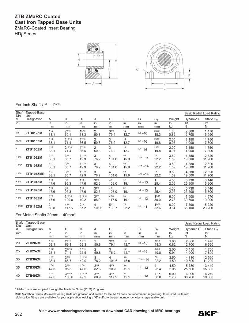
Shaft Tapped-Base Basic Radial Load RatingDia Unitd Designation A H H1 J L F G S1 Weight Dynamic C Static C0
mm in in in in in in in in lb lbf lbfmm mm mm mm mm mm mm mm kg N N
20 ZTB20ZM 11/2 29/16 15/16 2 31/8 1/23/8 –16
23/32 1.80 2 860 1 47038.1 65.1 33.3 50.8 79.4 12.7 18.3 0.82 12 700 6 550
25 ZTB25ZM 11/2 213/16 17/16 2 3 1/23/8 –16
25/32 2.00 3 150 1 75038.1 71.4 36.5 50.8 76.2 12.7 19.8 0.91 14 000 7 800
30 ZTB30ZM 11/2 33/8 111/16 3 4 5/87/16 –14
7/8 3.50 4 380 2 52038.1 85.7 42.9 76.2 101.6 15.9 22.2 1.59 19 500 11 200
35 ZTB35ZM 17/8 33/4 17/8 31/4 41/4 3/41/2 –13
1 4.50 5 730 3 44047.6 95.3 47.6 82.6 108.0 19.1 25.4 2.05 25 500 15 300
40 ZTB40ZM 17/8 315/16 115/16 31/2 45/8 3/41/2 –13
13/16 6.00 6 900 4 27047.6 100.0 49.2 88.9 117.5 19.1 30.0 2.73 30 700 19 000
282Visit www.mrcbearingservices.com to download CAD drawings of MRC bearings
ZTB ZMaRC Coated Cast Iron Tapped Base UnitsZMaRC-Coated Insert BearingHDi Series
Shaft Tapped-Base Basic Radial Load RatingDia Unitd Designation A H H1 J L F G S1 Weight Dynamic C Static C0
in in in in in in in in in lb lbf lbfmm mm mm mm mm mm mm mm kg N N
3/4 ZTB012ZM 11/2 29/16 15/16 2 31/8 1/23/8 –16
23/32 1.80 2 860 1 47038.1 65.1 33.3 50.8 79.4 12.7 18.3 0.82 12 700 6 550
15/16 ZTB015ZM 11/2 213/16 17/16 2 3 1/23/8 –16
25/32 2.05 3 150 1 75038.1 71.4 36.5 50.8 76.2 12.7 19.8 0.93 14 000 7 800
1 ZTB100ZM 11/2 213/16 17/16 2 3 1/23/8 –16
25/32 2.00 3 150 1 75038.1 71.4 36.5 50.8 76.2 12.7 19.8 0.91 14 000 7 800
11/8 ZTB102ZM 11/2 33/8 111/16 3 4 5/87/16 –14
7/8 3.50 4 380 2 52038.1 85.7 42.9 76.2 101.6 15.9 22.2 1.59 19 500 11 200
13/16 ZTB103ZM 11/2 33/8 111/16 3 4 5/87/16 –14
7/8 3.50 4 380 2 52038.1 85.7 42.9 76.2 101.6 15.9 22.2 1.59 19 500 11 200
11/4 ZTB104ZMR 11/2 33/8 111/16 3 4 5/87/16 –14
7/8 3.50 4 380 2 52038.1 85.7 42.9 76.2 101.6 15.9 22.2 1.59 19 500 11 200
11/4 ZTB104ZM 17/8 33/4 17/8 31/4 41/4 3/41/2 –13
1 4.50 5 730 3 44047.6 95.3 47.6 82.6 108.0 19.1 25.4 2.05 25 500 15 300
17/16 ZTB107ZM 17/8 33/4 17/8 31/4 41/4 3/41/2 –13
1 4.50 5 730 3 44047.6 95.3 47.6 82.6 108.0 19.1 25.4 2.05 25 500 15 300
11/2 ZTB108ZM 17/8 315/16 115/16 31/2 45/8 3/41/2 –13
13/16 6.00 6 900 4 27047.6 100.0 49.2 88.9 117.5 19.1 30.0 2.73 30 700 19 000
115/16 ZTB115ZM 2 45/8 21/4 4 51/2 7/85/8 –11
19/32 8.00 7 890 5 22050.8 117.5 57.2 101.6 139.7 22.2 32.6 3.64 35 100 23 200
* Metric units are supplied through the Made To Order (MTO) Program
MRC Marathon Series Mounted Bearing Units are greased and sealed for life. MRC does not recommend regreasing. If required, units with relubrication fittings are available for your application. Adding a “G” suffix to the part number denotes a regreasable unit.
For Metric Shafts 20mm – 40mm*
For Inch Shafts 3/4 – 115/16

283
For Inch Shafts 3/4 – 11/2
Shaft Pillow J J Basic Radial Load RatingDia Blockd Designation A A1 H H1 H2 Min Max L N N1 G S1 Dynamic C Static Coin in in in in in in in in in in in in lbf lbf
mm mm mm mm mm mm mm mm mm mm mm mm N N
3/4 SPB012SS 11/4 3/4 21/2 15/16 35/64 37/16 43/16 5 13/16 29/64 3/8 23/32 2 400 1 47032.0 19.0 64.0 33.3 14.0 87.3 106.4 127.0 20.5 11.5 10.0 18.3 10 800 6 550
1 SPB100SS 17/16 7/8 23/4 17/16 5/8 311/16 45/16 51/8 3/4 29/64 3/8 25/32 2 700 175036.0 22.0 70.0 36.5 16.0 93.7 109.5 130.0 19.1 11.5 10.0 19.8 11 900 7 800
13/16 SPB103SS 19/16 1 315/64 111/16 21/32 41/4 5 6 15/16 9/16 1/2 7/8 3 700 2 52039.7 25.4 82.0 42.9 16.5 108.0 127.0 152.4 23.8 14.3 12.7 22.2 16 300 11 200
11/4 SPB104SSR 19/16 1 315/64 111/16 21/32 41/4 5 6 15/16 9/16 1/2 7/8 3 700 2 52039.7 25.4 82.0 42.9 16.5 108.0 127.0 152.4 23.8 14.3 12.7 22.2 16 300 11 200
11/4 SPB104SS 13/4 11/8 321/32 17/8 3/4 411/16 51/4 65/16 27/32 9/16 1/2 1 4 900 3 44044.5 28.6 93.0 47.6 19.0 119.1 133.4 160.3 21.4 14.3 12.7 25.4 21 600 15 300
13/8 SPB106SS 13/4 11/8 321/32 17/8 3/4 411/16 51/4 65/16 27/32 9/16 1/2 1 4 900 3 44044.5 28.6 93.0 47.6 19.0 119.1 133.4 160.3 21.4 14.3 12.7 25.4 21 600 15 300
17/16 SPB107SS 13/4 11/8 321/32 17/8 3/4 411/16 51/4 65/16 27/32 9/16 1/2 1 4 900 3 44044.5 28.6 93.0 47.6 19.0 119.1 133.4 160.3 21.4 14.3 12.7 25.4 21 600 15 300
11/2 SPB108SS 17/8 11/4 329/32 115/16 3/4 415/16 53/4 67/8 31/32 9/16 1/2 13/16 5 600 4 27047.6 31.2 99.0 49.2 19.0 125.4 146.0 174.6 24.6 14.3 12.7 30.0 24 700 19 000
SPB Cast Stainless SteelPillow Block Units
Stainless Steel Insert BearingXDs Series
Shaft Pillow J J Basic Radial Load RatingDia Blockd Designation A A1 H H1 H2 Min Max L N N1 G S1 Dynamic C Static Comm in in in in in in in in in in in in lbf lbf
mm mm mm mm mm mm mm mm mm mm mm mm N N
For Metric Shafts 20mm – 40mm*
20 SPB20SS 11/4 3/4 21/2 15/16 35/64 37/16 43/16 5 13/16 29/64 3/8 23/32 2 400 1 47032.0 19.0 64.0 33.3 14.0 87.3 106.4 127.0 20.5 11.5 10.0 18.3 10 800 6 550
25 SPB25SS 17/16 7/8 23/4 17/16 5/8 311/16 45/16 51/8 3/4 29/64 3/8 25/32 2 700 1 75036.0 22.0 70.0 36.5 16.0 93.7 109.5 130.0 19.1 11.5 10.0 19.8 11 900 7 800
30 SPB30SS 19/16 1 315/64 111/16 21/32 41/4 5 6 15/16 9/16 1/2 7/8 3 700 2 52039.7 25.4 82.0 42.9 16.5 108.0 127.0 152.4 23.8 14.3 12.7 22.2 16 300 11 200
35 SPB35SS 13/4 11/8 321/32 17/8 3/4 411/16 51/4 65/16 27/32 9/16 1/2 1 4 900 3 44044.5 28.6 93.0 47.6 19.0 119.1 133.4 160.3 21.4 14.3 12.7 25.4 21 600 15 300
40 SPB40SS 17/8 11/4 329/32 115/16 3/4 415/16 53/4 67/8 31/32 9/16 1/2 13/16 5 600 4 27047.6 31.2 99.0 49.2 19.0 125.4 146.0 174.6 24.6 14.3 12.7 30.0 24 700 19 000
* Metric units are supplied through the Made To Order (MTO) Program
MRC Marathon Series Mounted Bearing Units are greased and sealed for life. MRC does not recommend regreasing. If required, unitswith relubrication fittings are available for your application. Adding a “G” suffix to the part number denotes a regreasable unit.

284Visit www.mrcbearingservices.com to download CAD drawings of MRC bearings
For Inch Shafts 3/4 – 11/2
Shaft Flange Basic Radial Load RatingDia Unitd Designation A1 A2 H J L N G T Dynamic C Static Coin in in in in in in in in lbf lbf
mm mm mm mm mm mm mm mm N N
3/4 S2F012SS 11/64 7/16 413/32 317/32 23/8 7/16 3/8 19/32 2 400 1 47025.8 11.1 111.9 89.7 60.3 11.1 10.0 32.5 10 800 6 550
1 S2F100SS 15/32 17/32 47/8 357/64 23/4 1/2 7/16 17/16 2 700 1 75029.4 13.5 123.4 98.8 69.9 12.7 11.0 36.5 11 900 7 800
13/16 S2F103SS 111/32 17/32 59/16 419/32 31/8 1/2 7/16 121/32 3 700 2 52034.1 13.5 141.3 116.7 79.4 12.7 11.0 42.1 16 300 11 200
11/4 S2F104SSR 111/32 17/32 59/16 419/32 31/8 1/2 7/16 121/32 3 700 2 52034.1 13.5 141.3 116.7 79.4 12.7 11.0 42.1 16 300 11 200
11/4 S2F104SS 113/32 9/16 61/8 51/8 35/8 9/16 1/2 113/16 4 900 3 44035.7 14.3 155.6 130.2 92.1 14.3 12.7 46.0 21 600 15 300
13/8 S2F106SS 113/32 9/16 61/8 51/8 35/8 9/16 1/2 113/16 4 900 3 44035.7 14.3 155.6 130.2 92.1 14.3 12.7 46.0 21 600 15 300
17/16 S2F107SS 113/32 9/16 61/8 51/8 35/8 9/16 1/2 113/16 4 900 3 44035.7 14.3 155.6 130.2 92.1 14.3 12.7 46.0 21 600 15 300
11/2 S2F108SS 117/32 9/16 63/4 521/32 4 9/16 1/2 23/32 5 600 4 27038.9 14.3 171.5 143.7 101.6 14.3 12.7 53.0 24 700 19 000
S2F Cast Stainless SteelTwo-Bolt Flange UnitsStainless Steel Insert BearingXDs Series
For Metric Shafts 20mm – 40mm*
Shaft Flange Basic Radial Load RatingDia Unitd Designation A1 A2 H J L N G T Dynamic C Static Comm in in in in in in in in lbf lbf
mm mm mm mm mm mm mm mm N N
20 S2F20SS 11/64 7/16 413/32 317/32 23/8 7/16 3/8 19/32 2 400 1 47025.8 11.1 111.9 89.7 60.3 11.1 10.0 32.5 10 800 6 550
25 S2F25SS 15/32 17/32 47/8 357/64 23/4 1/2 7/16 17/16 2 700 1 75029.4 13.5 123.4 98.8 69.9 12.7 11.0 36.5 11 900 7 800
30 S2F30SS 111/32 17/32 59/16 419/32 31/8 1/2 7/16 121/32 3 700 2 52034.1 13.5 141.3 116.7 79.4 12.7 11.0 42.1 16 300 11 200
35 S2F35SS 113/32 9/16 61/8 51/8 35/8 9/16 1/2 113/16 4 900 3 44035.7 14.3 155.6 130.2 92.1 14.3 12.7 46.0 21 600 15 300
40 S2F40SS 117/32 9/16 63/4 521/32 4 9/16 1/2 23/32 5 600 4 27038.9 14.3 171.5 143.7 101.6 14.3 12.7 53.0 24 700 19 000
* Metric units are supplied through the Made To Order (MTO) Program
MRC Marathon Series Mounted Bearing Units are greased and sealed for life. MRC does not recommend regreasing. If required, units with relubricationfittings are available for your application. Adding a “G” suffix to the part number denotes a regreasable unit.
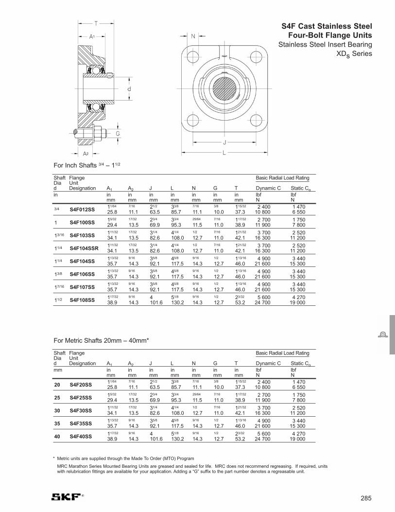
285
For Inch Shafts 3/4 – 11/2
Shaft Flange Basic Radial Load RatingDia Unitd Designation A1 A2 J L N G T Dynamic C Static Coin in in in in in in in lbf lbf
mm mm mm mm mm mm mm N N
3/4 S4F012SS 11/64 7/16 21/2 33/8 7/16 3/8 115/32 2 400 1 47025.8 11.1 63.5 85.7 11.1 10.0 37.3 10 800 6 550
1 S4F100SS 15/32 17/32 23/4 33/4 29/64 7/16 117/32 2 700 1 75029.4 13.5 69.9 95.3 11.5 11.0 38.9 11 900 7 800
13/16 S4F103SS 111/32 17/32 31/4 41/4 1/2 7/16 121/32 3 700 2 52034.1 13.5 82.6 108.0 12.7 11.0 42.1 16 300 11 200
11/4 S4F104SSR 111/32 17/32 31/4 41/4 1/2 7/16 121/32 3 700 2 52034.1 13.5 82.6 108.0 12.7 11.0 42.1 16 300 11 200
11/4 S4F104SS 113/32 9/16 35/8 45/8 9/16 1/2 113/16 4 900 3 44035.7 14.3 92.1 117.5 14.3 12.7 46.0 21 600 15 300
13/8 S4F106SS 113/32 9/16 35/8 45/8 9/16 1/2 113/16 4 900 3 44035.7 14.3 92.1 117.5 14.3 12.7 46.0 21 600 15 300
17/16 S4F107SS 113/32 9/16 35/8 45/8 9/16 1/2 113/16 4 900 3 44035.7 14.3 92.1 117.5 14.3 12.7 46.0 21 600 15 300
11/2 S4F108SS 117/32 9/16 4 51/8 9/16 1/2 23/32 5 600 4 27038.9 14.3 101.6 130.2 14.3 12.7 53.2 24 700 19 000
S4F Cast Stainless SteelFour-Bolt Flange Units
Stainless Steel Insert BearingXDs Series
For Metric Shafts 20mm – 40mm*
Shaft Flange Basic Radial Load RatingDia Unitd Designation A1 A2 J L N G T Dynamic C Static Comm in in in in in in in lbf lbf
mm mm mm mm mm mm mm N N
20 S4F20SS 11/64 7/16 21/2 33/8 7/16 3/8 115/32 2 400 1 47025.8 11.1 63.5 85.7 11.1 10.0 37.3 10 800 6 550
25 S4F25SS 15/32 17/32 23/4 33/4 29/64 7/16 117/32 2 700 1 75029.4 13.5 69.9 95.3 11.5 11.0 38.9 11 900 7 800
30 S4F30SS 111/32 17/32 31/4 41/4 1/2 7/16 121/32 3 700 2 52034.1 13.5 82.6 108.0 12.7 11.0 42.1 16 300 11 200
35 S4F35SS 113/32 9/16 35/8 45/8 9/16 1/2 113/16 4 900 3 44035.7 14.3 92.1 117.5 14.3 12.7 46.0 21 600 15 300
40 S4F40SS 117/32 9/16 4 51/8 9/16 1/2 23/32 5 600 4 27038.9 14.3 101.6 130.2 14.3 12.7 53.2 24 700 19 000
* Metric units are supplied through the Made To Order (MTO) Program
MRC Marathon Series Mounted Bearing Units are greased and sealed for life. MRC does not recommend regreasing. If required, unitswith relubrication fittings are available for your application. Adding a “G” suffix to the part number denotes a regreasable unit.

286Visit www.mrcbearingservices.com to download CAD drawings of MRC bearings
* Metric units are supplied through the Made To Order (MTO) Program
MRC Marathon Series Mounted Bearing Units are greased and sealed for life. MRC does not recommend regreasing. If required, units with relubricationfittings are available for your application. Adding a “G” suffix to the part number denotes a regreasable unit.
For Inch Shafts 3/4 – 11/2
Shaft Tapped-Base Basic Radial Load RatingDia Unitd Designation A H H1 J L F G S1 Dynamic C Static Coin in in in in in in UNC in lbf lbf
mm mm mm mm mm mm Threads mm N N
STB Cast Stainless SteelTapped Base UnitsStainless Steel Insert BearingXDs Series
For Metric Shafts 20mm – 40mm*
Shaft Tapped-Base Basic Radial Load RatingDia Unitd Designation A H H1 J L F G S1 Dynamic C Static Comm in in in in in in UNC in lbf lbf
mm mm mm mm mm mm Threads mm N N
20 STB20SS 11/8 21/2 15/16 2 25/8 1/23/8 –16
23/32 2 400 1 47028.6 63.5 33.3 50.8 66.7 12.7 18.3 10 800 6 550
25 STB25SS 11/4 23/4 17/16 2 3 1/23/8 –16
25/32 2 700 1 75031.8 69.9 36.5 50.8 76.2 12.7 19.8 11 900 7 800
30 STB30SS 11/2 31/4 111/16 3 37/8 5/87/16 –14
7/8 3 700 2 52038.1 82.6 42.9 76.2 98.4 15.9 22.2 16 300 11 200
35 STB35SS 11/2 35/8 17/8 31/4 41/8 3/41/2 –13 1 4 900 3 440
38.1 92.1 47.6 82.6 104.8 19.1 25.4 21 600 15 300
40 STB40SS 15/8 315/16 115/16 31/2 41/2 3/41/2 –13 13/16 5 600 4 270
41.3 100.0 49.2 88.9 114.3 19.1 30.0 24 700 19 000
3/4 STB012SS 11/8 21/2 15/16 2 25/8 1/23/8 –16
23/32 2 400 1 47028.6 63.5 33.3 50.8 66.7 12.7 18.3 10 800 6 550
1 STB100SS 11/4 23/4 17/16 2 3 1/23/8 –16
25/32 2 700 1 75031.8 69.9 36.5 50.8 76.2 12.7 19.8 11 900 7 800
13/16 STB103SS 11/2 31/4 111/16 3 37/8 5/87/16 –14
7/8 3 700 2 52038.1 82.6 42.9 76.2 98.4 15.9 22.2 16 300 11 200
11/4 STB104SSR 11/2 31/4 111/16 3 37/8 5/87/16 –14
7/8 3 700 2 52038.1 82.6 42.9 76.2 98.4 15.9 22.2 16 300 11 200
11/4 STB104SS 11/2 35/8 17/8 31/4 41/8 3/41/2 –13 1 4 900 3 440
38.1 92.1 47.6 82.6 104.8 19.1 25.4 21 600 15 300
13/8 STB106SS 11/2 35/8 17/8 31/4 41/8 3/41/2 –13 1 4 900 3 440
38.1 92.1 47.6 82.6 104.8 19.1 25.4 21 600 15 300
17/16 STB107SS 11/2 35/8 17/8 31/4 41/8 3/41/2 –13 1 4 900 3 440
38.1 92.1 47.6 82.6 104.8 19.1 25.4 21 600 15 300
11/2 STB108SS15/8 315/16 115/16 31/2 41/2 3/4
1/2 –13 13/16 5 600 4 27041.3 100.0 49.2 88.9 114.3 19.1 30.0 24 700 19 000

287
Sleeves
Adapter Sleeves
Prefixes
H Sleeve for shafts in metricdimensions*
HA Sleeve for shafts of 1/16"increments
HE Sleeve for shafts of 1/4"increments
HS Sleeve for shafts of 1/8"increments
OH Oil hole in large end of sleeveto inject oil between the sleeveand the bearing generally formetric shafts sizes if inch an example would be OHA-----.
OH..B Oil injected between bearing,sleeve and shaft. Sizes 32-40;one oil-supply duct from largeend of sleeve. Size > 44, twooil supply ducts from large endof sleeve.
OH..H Oil injected between bearingand sleeve, one oil supply ductfrom nut side of sleeve.
OH..HBOil injected between bearing,sleeve and shaft. Sizes 32-40:One oil-supply duct from nutside of sleeve. Size > 44 up;Two oil supply ducts from nutside of sleeve.
Suffixes
B Whitworth threads
C Sleeves with ribbed washer tobe used with sealed bearings**
E The standard lock nut andwasher is replaced by a KMFE,washerless nut or the standardlock nut HM30 is replaced by an HME nut with a recessedoutside diameter.
HE HME locknut used
L Sleeves with low section heightnuts and washers (KML & MBLvs. KM & MB)
TL The standard HM..T nut andMB washer, have beenreplaced by HM30 and MS 30 nut and washer. These have alower section height.
U Sleeve only (no nut/washer)
USA design
SNW Inch dimensions and fitted withN & AN locknuts and W and W0washers.
SNP Inch dimensions and fitted withN locknuts and PL lockplates
Specifications
Metric sleeves To ISO 2982-1: 1995
Inch sleeves To ANSI/ABMA Std. 8.2.
Withdrawal sleeves
Prefixes
AH Standard withdrawal sleeve,preservative coated (metric)2)
AHX Modified AH (metric)2)
AHA U.S.A. variant1)
SK U.S.A. variant1)
ASK U.S.A. variant1)
1) Being phased out2) Sizes 04-40 now zinc phosphated
AOH Metric sleeves having a borediameter of 200 mm and aboveare supplied as standard withtwo oil-supply ducts at the threaded side and havedistribution grooves around thecircumference and in the axialdirection on the outside surfaceas well as in the bore.2)
AOHX Modified AOH
Suffix
G Thread pitch diameter changedto adhere to ISO specifications
Special Features
Note: Up to size 40, the sleeves arephosphated. Larger sizes areuntreated and oiled.
* Occasionally a metric sleeve will beused for an inch dimension shaftbecause the two dimensions arealmost identical, i.e. 3 15/16" and100 mm.
** Other low section height sleeves canalso be used with sealed bearings.
*** Some sealed bearings require widersleeves.

B2
B1
d1 G dd
3
B2 B2
288
Metric Sleevesd 17 - 55 mm
17 20 32 24 7 M 20x1 0.036 H 204 KM 4 MB 4 – 1204 EK20 32 28 7 M 20x1 0.04 H 304 KM 4 MB 4 – 2204 EK, 1304 EK
20 25 38 26 8 M 25x1.5 0.064 H 205 KM 5 MB 5 – 1205 EK25 38 29 8 M 25x1.5 0.071 H 305 KM 5 MB 5 – 2205 EK, 1305 EK, 22205 EK25 38 29 8.5 M 25x1.5 0.071 H 305 C KM 5 MB 5 C – 2205 E-2RS1KTN925 38 29 10.5 M 25x1.5 0.076 H 305 E KMFE 5 – –
25 30 45 27 8 M 30x1.5 0.086 H 206 KM 6 MB 6 – 1206 EK30 45 31 8 M 30x1.5 0.095 H 306 KM 6 MB 6 – 2206 EK, 1306 EK, 22206 EK30 45 31 8.5 M 30x1.5 0.095 H 306 C KM 6 MB 6 C – 2206 E-2RS1KTN930 45 31 10.5 M 30x1.5 0.11 H 306 E KMFE 6 – – C 2206 KTN9, C 2206 KV30 45 38 8 M 30x1.5 0.11 H 2306 KM 6 MB 6 – 2306 K
30 35 52 29 9 M 35x1.5 0.12 H 207 KM 7 MB 7 – 1207 EK35 52 35 9 M 35x1.5 0.14 H 307 KM 7 MB 7 – 2207 EK, 1307 EK, 22207 EK35 52 35 9.5 M 35x1.5 0.14 H 307 C KM 7 MB 7 C – 2207 E-2RS1KTN935 52 35 11.5 M 35x1.5 0.15 H 307 E KMFE 7 – – C 2207 KTN9, C 2207 KV35 52 43 9 M 35x1.5 0.16 H 2307 KM 7 MB 7 – 2307 EK
35 40 58 31 10 M 40x1.5 0.16 H 208 KM 8 MB 8 – 1208 EK40 58 36 10 M 40x1.5 0.17 H 308 KM 8 MB 8 – 2208 EK, 1308 EK, 22208 EK, 21308 CCK,C2208 KV40 58 36 10.5 M 40x1.5 0.17 H 308 C KM 8 MB 8 C – 2208 E-2RS1KTN940 58 36 13 M 40x1.5 0.19 H 308 E KMFE 8 – – C2208 KTN940 58 46 10 M 40x1.5 0.22 H 2308 KM 8 MB 8 – 2308 EK, 22308 EK
40 45 65 33 11 M 45x1.5 0.21 H 209 KM 9 MB 9 – 1209 EK45 65 39 11 M 45x1.5 0.23 H 309 KM 9 MB 9 – 2209 EK, 1309 EK, 22209 EK, 21309 CCK45 65 39 11.5 M 45x1.5 0.23 H 309 C KM 9 MB 9 C – 2209 E-2RS1KTN945 65 39 13 M 45x1.5 0.24 H 309 E KMFE 9 – – C 2209 KTN9, C2209 KV45 65 50 11 M 45x1.5 0.27 H 2309 KM 9 MB 9 – 2309 EK, 22309 EK
45 50 70 35 12 M 50x1.5 0.24 H 210 KM 10 MB 10 HMV 10 E 1210 EK50 70 42 12 M 50x1.5 0.27 H 310 KM 10 MB 10 HMV 10 E 2210 EK, 1310 EK, 22210 EK, 21310 CCK50 70 42 12.5 M 50x1.5 0.27 H 310 C KM 10 MB 10 C HMV 10 E 2210-2RS1KTN950 70 42 14 M 50x1.5 0.3 H 310 E KMFE 10 – HMV 10 E C 2210 KTN9, C 2210 KV 50 70 55 12 M 50x1.5 0.34 H 2310 KM 10 MB 10 HMV 10 E 2310 K, 22310 EK
50 55 75 37 12.5 M 55x2 0.28 H 211 KM 11 MB 11 HMV 11 E 1211 EK55 75 45 12.5 M 55x2 0.32 H 311 KM 11 MB 11 HMV 11 E 2211 EK, 1311 EK, 22211 EK, 21311 CCK55 75 45 13 M 55x2 0.32 H 311 C KM 11 MB 11 C HMV 11 E 2211 E-2RS1KTN955 75 45 14 M 55x2 0.34 H 311 E KMFE 11 – HMV 11 E C 2211 KTN9, C2211 KV55 75 59 12.5 M 55x2 0.39 H 2311 KM 11 MB 11 HMV 11 E 2311 K, 22311 EK
55 60 80 38 13 M 60x2 0.31 H 212 KM 12 MB 12 HMV 12 E 1212 EK60 80 47 13 M 60x2 0.36 H 312 KM 12 MB 12 HMV 12 E 2212 EK, 1312 EK, 22212 EK, 21312 CCK, C 2212 KV60 80 47 14 M 60x2 0.4 H 312 E KMFE 12 – HMV 12 E C 2212 KTN960 80 62 13 M 60x2 0.45 H 2312 KM 12 MB 12 HMV 12 E 2312 K, 22312 EK
Dimensions Mass DesignationsAdptr. sleeve Lock Locking Appropriate bearing(s)with nut and nut device hydraulic
d1 d d3 B1 B2 G lock device nut
mm kg –
H, H .. L H .. E H .. C

289
60 65 85 40 14 M 65x2 0.36 H 213 KM 13 MB 13 HMV 13 E 1213 EK65 85 50 14 M 65x2 0.42 H 313 KM 13 MB 13 HMV 13 E 2213 EK, 1313 EK, 22213 EK, 21213 CCK, C 2213 KV65 85 50 15 M 65x2 0.42 H 313 C KM 13 MB 13 C HMV 13 E 22213 E-2RS1KTN965 85 50 15 M 65x2 0.43 H 313 E KMFE 13 – HMV 13 E C 2213 KTN965 85 65 14 M 65x2 0.52 H 2313 KM 13 MB 13 HMV 13 E 2313 K, 22313 EK
70 92 52 14 M 70x2 0.67 H 314 KM 14 MB 14 HMV 14 E 22214EK, 21314 CCK,C 2214 KV70 92 52 15 M 70x2 0.67 H 314 E KMFE 14 – HMV 14 E C 2214 KTN970 92 68 14 M 70x2 0.88 H 2314 KM 14 MB 14 HMV 14 E 22314 EK, C 2314 K
65 75 98 43 15 M 75x2 0.66 H 215 KM 15 MB 15 HMV 15 E 1215 K75 98 55 15 M 75x2 0.78 H 315 KM 15 MB 15 HMV 15 E 2215 K, 1315 K, 22215 EK, 21315 CCK, C 2215 KV75 98 55 16 M 75x2 0.8 H 315 E KMFE 15 – HMV 15 E C 2215 K75 98 73 15 M 75x2 1.1 H 2315 KM 15 MB 15 HMV 15 E 2315 K, 22315 EK, C 2315 K
70 80 105 46 17 M 80x2 0.81 H 216 KM 16 MB 16 HMV 16 E 1216 K80 105 59 17 M 80x2 0.95 H 316 KM 16 MB 16 HMV 16 E 2216 EK, 1316 K, 22216 EK, 21316 CCK. C 2216 KV80 105 59 18 M 80x2 1.01 H 316 E KMFE 16 – HMV 16 E C 2216 K80 105 78 17 M 80x2 1.2 H 2316 KM 16 MB 16 HMV 16 E 2316 K, 22316 EK, C 2316 K
75 85 110 50 18 M 85x2 0.94 H 217 KM 17 MB 17 HMV 17 E 1217 K85 110 63 18 M 85x2 1.1 H 317 KM 17 MB 17 HMV 17 E 2217 K, 1317 K, 22217 EK, 21317 CCK, C 2217 KV85 110 63 19 M 85x2 1.17 H 317 E KMFE 17 – HMV 17 E C 2217 K85 110 82 18 M 85x2 1.35 H 2317 KM 17 MB 17 HMV 17 E 2317 K, 22317 EK, C 2317 K
80 90 120 52 18 M 90x2 1.1 H 218 KM 18 MB 18 HMV 18 E 1218 K90 120 65 18 M 90x2 1.3 H 318 KM 18 MB 18 HMV 18 E 2218 K, 1318 K, 22218 EK, 21318 CCK, C2218 KV90 120 65 19 M 90x2 1.43 H 318 E KMFE 18 – HMV 18 E C 2218 K90 120 86 18 M 90x2 1.6 H 2318 KM 18 MB 18 HMV 18 E 2318 K, 23218 CCK/W33, 22318 EK, C2318 K
85 95 125 55 19 M 95x2 1.25 H 219 KM 19 MB 19 HMV 19 E 1219 K95 125 68 19 M 95x2 1.4 H 319 KM 19 MB 19 HMV 19 E 2219 K, 1319K, 22219 EK, 21319 CCK95 125 68 20 M 95x2 1.41 H 319 E KMFE 19 – HMV 19 E C 2219 K95 125 90 19 M 95x2 1.8 H 2319 KM 19 MB 19 HMV 19 E 2319 K, 22319 EK, C 2319 K
90 100 130 58 20 M 100x2 1.4 H 220 KM 20 MB 20 HMV 20 E 1220 K100 130 71 20 M 100x2 1.6 H 320 KM 20 MB 20 HMV 20 E 2220 K, 1320 K, 22220 EK, 21320 CCK, 100 130 71 21 M 100x2 1.72 H 320 E KMFE 20 – HMV 20 E C 2220 K100 130 76 20 M 100x2 1.8 H 3120 KM 20 MB 20 HMV 20 E 23120 CCK/W33, C 3120 K, C3120 KV100 130 97 20 M 100x2 2 H 2320 KM 20 MB 20 HMV 20 E 2320 K, 23220 CCK/W33, 22320 EK, C2320 K
100 110 145 63 21 M 110x2 1.8 H 222 KM 22 MB 22 HMV 22 E 1222 K110 145 77 21 M 110x2 2.04 H 322 KM 22 MB 22 HMV 22 E 2222 K, 1322 K, 23022 CCK, 22222 EK, 21322 CCK110 145 77 21.5 M 110x2 2.11 H 322 E KMFE 22 – HMV 22 E C 3022 K, C 2222 K110 145 81 21 M 110x2 2.1 H 3122 KM 22 MB 22 HMV 22 E 23122 CCK/W33110 145 105 21 M 110x2 2.75 H 2322 KM 22 MB 22 HMV 22 E 2322 K, 23222 CCK/W33, 22322 EK
110 120 145 72 22 M 120x2 1.8 H 3024 KML 24 MBL 24 HMV 24 E 1224 K, 23024 CCK/W33, C3024 K120 155 72 26 M 120x2 1.87 H 3024 E KMFE 24 – HMV 24 E C 3024 K120 155 88 22 M 120x2 2.5 H 3124 KM 24 MB 24 HMV 24 E 23124 CCCK/W33, 22224 EK120 145 88 22 M 120x2 2.5 H 3124 L KML 24 MBL 24 HMV 24 E C 2224 K120 155 112 22 M 120x2 3 H 2324 KM 24 MB 24 HMV 24 E 23224 CCK/W33, 22324 CCK/W33120 145 112 22 M 120x2 3.12 H 2324 L KML 24 MBL 24 HMV 24 E C 3224 K
Dimensions Mass DesignationsAdptr. sleeve Lock Locking Appropriate bearing(s)with nut and nut device hydraulic
d1 d d3 B1 B2 G lock device nut
mm kg –
Metric Sleevesd 60 - 110 mm

290
Metric Sleevesd 115 - 180 mm
115 130 155 80 23 M 130x2 2.8 H 3026 KML 26 MBL 26 HMV 26 E 23026 CCK/W33, C3026 K130 165 92 23 M 130x2 3.45 H 3126 KM 26 MB 26 HMV 26 E 23126 CCK/W33, 22226 EK130 155 92 23 M 130x2 3.65 H 3126 L KML 26 MBL 26 HMV 26 E C 2226 K130 165 121 23 M 130x2 4.45 H 2326 KM 26 MB 26 HMV 26 E 23226 CCK/W33, 22326 CCK/W33
125 140 165 82 24 M 140x2 3.05 H 3028 KML 28 MBL 28 HMV 28 E 23028 CCK/W33, C 3028 K140 180 97 24 M 140x2 4.1 H 3128 KM 28 MB 28 HMV 28 E 23128 CCK/W33, 22228 CCK/W33 140 165 97 24 M 140x2 3.62 H 3128 L KML 28 MBL 28 HMV 28 E C 2228 K140 180 131 24 M 140x2 5.4 H 2328 KM 28 MB 28 HMV 28 E 23228 CCK/W33, 22328 CCK/W33
135 150 180 87 26 M 150x2 3.75 H 3030 KML 30 MBL 30 HMV 30 E 23030 CCK/W33150 195 111 26 M 150x2 5.25 H 3130 KM 30 MB 30 HMV 30 E 23130 CCK/W33, 22230 CCK/W33150 180 111 26 M 150x2 4.7 H 3130 L KML 30 MBL 30 HMV 30 E C 3130 K, 2230 K, C3130 K, C2230 K150 195 139 26 M 150x2 6.4 H 2330 KM 30 MB 30 HMV 30 E 23230 CCK/W33, 22330 CCK/W33
140 160 190 93 27.5 M 160x3 5.1 H 3032 KML 32 MBL 32 HMV 32 E 23032 CCK/W33, C3032 K160 210 119 27.5 M 160x3 7.25 H 3132 KM 32 MB 32 HMV 32 E 23132 CCK/W33, 22232 CCK/W33160 190 119 27.5 M 160x3 6.4 H 3132 L KML 32 MBL 32 HMV 32 E C 3132 K160 210 147 27.5 M 160x3 8.8 H 2332 KM 32 MB 32 HMV 32 E 23232 CCK/W33, 22332 CCK/W33160 190 147 27.5 M 160x3 7.95 H 2332 L KML 32 MBL 32 HMV 32 E C 3232 K
150 170 200 101 28.5 M 170x3 5.8 H 3034 KML 34 MBL 34 HMV 34 E 23034 CCK/W33, C 3034 K170 220 122 28.5 M 170x3 8.1 H 3134 KM 34 MB 34 HMV 34 E 23134 CCK/W33, 22234 CCK/W33170 200 122 28.5 M 170x3 7.15 H 3134 L KML 34 MBL 34 HMV 34 E C 3134 K, C2334 K170 220 154 28.5 M 170x3 9.9 H 2334 KM 34 MB 34 HMV 34 E 23234 CCK/W33, 22334 CCK/W33
160 180 210 87 29.5 M 180x3 5.7 H 3936 KML 36 MBL 36 HMV 36 E 23936 CCK/W33180 210 109 29.5 M 180x3 6.7 H 3036 KML 36 MBL 36 HMV 36 E 23036 CCK/W33, C3036 K180 230 131 29.5 M 180x3 9.15 H 3136 KM 36 MB 36 HMV 36 E 23136 CCK/W33, 22236 CCK/W33180 210 131 29.5 M 180x3 8.15 H 3136 L KML 36 MBL 36 HMV 36 E C 3136 K180 230 161 30 M 180x3 11 H 2336 KM 36 MB 36 HMV 36 E 23236 CCK/W33, 22336 CCK/W33, C3236 K
170 190 220 89 30.5 M 190x3 6.2 H 3938 KML 38 MBL 38 HMV 38 E 23938 CCK/W33190 220 112 30.5 M 190x3 7.25 H 3038 KML 38 MBL 38 HMV 38 E 23038 CCK/W33, C 3038 K190 240 141 30.5 M 190x3 10.5 H 3138 KM 38 MB 38 HMV 38 E 23138 CCK/W33, 22238 CCK/W33190 240 169 30.5 M 190x3 12 H 2338 KM 38 MB 38 HMV 38 E 23238 CCK/W33, 22338 CCK/W33
180 200 240 98 31.5 M 200x3 7.9 H 3940 KML 40 MBL 40 HMV 40 E 23940 CCK/W33200 240 120 31.5 M 200x3 8.9 H 3040 KML 40 MBL 40 HMV 40 E 23040 CCK/W33, C 3040 K200 250 150 31.5 M 200x3 12 H 3140 KM 40 MB 40 HMV 40 E 23140 CCK/W33, 22240 CCK/W33, C3140 K200 250 176 31.5 M 200x3 13.5 H 2340 KM 40 MB 40 HMV 40 E 23240 CCK/W33, 22340 CCK/W33
Dimensions Mass DesignationsAdptr. sleeve Lock Locking Appropriate bearing(s)with nut and nut device hydraulic
d1 d d3 B1 B2 G lock device nut
mm kg –
B2
B1
d1 G dd
3
B2 B2
H, H .. L H .. E H .. C

291
200 220 260 96 30 41 Tr 220x4 M 6 4.2 7.95 OH 3944 H HM 3044 MS 3044 HMV 44 E 23944 CCK/W33220 260 126 30 41 Tr 220x4 M 6 4.2 9.9 OH 3044 H HM 3044 MS 3044 HMV 44 E C 3044 K220 280 161 35 – Tr 220x4 M 6 4.2 15 OH 3144 H HM 44 T MB 44 HMV 44 E 23144 CCK/W33, 22244 CCK/W33,
C 2244 K220 260 161 30 41 Tr 220x4 M 6 4.2 14.3 OH 3144 HTL HM 3044 MS 3044 HMV 44 E C 3144 K220 280 186 35 – Tr 220x4 M 6 4.2 17 OH 2344 H HM 44 T MB 44 HMV 44 E 23244 CCK/W33, 22344 CCK/W33
220 240 290 101 34 46 Tr 240x4 M 6 4.2 11 OH 3948 H HM 3048 MS 3052-48 HMV 48 E 23948 CCK/W33240 290 133 34 46 Tr 240x4 M 6 4.2 12 OH 3048 H HM 3048 MS 3052-48 HMV 48 E 23048 CCK/W33, C 3048 K240 300 172 37 – Tr 240x4 M 6 4.2 16.5 OH 3148 H HM 48 T MB 48 HMV 48 E 23148 CCK/W33, 22248 CCK/W33240 290 172 34 46 Tr 240x4 M 6 4.2 15.1 OH 3148 HTL HM 3048 MS 3052-48 HMV 48 E C 3148 K240 300 199 37 – Tr 240x4 M 6 4.2 19 OH 2348 H HM 48 T MB 48 HMV 48 E 23248 CCK/W33, 22348 CCK/W33
240 260 310 116 34 46 Tr 260x4 M 6 4.2 11.7 OH 3952 H HM 3052 MS 3052-48 HMV 52 E 23952 CCK/W33260 310 145 34 46 Tr 260x4 M 6 4.2 13.5 OH 3052 H HM 3052 MS 3052-48 HMV 52 E 23052 CCK/W33, 260 330 190 39 – Tr 260x4 M 6 4.2 21 OH 3152 H HM 52 T MB 52 HMV 52 E 23152 CCK/W33, 22252 CACK/W33260 310 190 34 46 Tr 260x4 M 6 4.2 17.7 OH 3152 HTL HM 3052 MS 3052-48 HMV 52 E C 3152 K260 330 211 39 – Tr 260x4 M 6 4.2 23 OH 2352 H HM 52 T MB 52 HMV 52 E 23252 CCK/W33, 22352 CACK/W33
260 280 330 121 38 50 Tr 280x4 M 6 4.2 15.3 OH 3956 H HM 3056 MS 3056 HMV 56 E 23956 CCK/W33280 330 152 38 50 Tr 280x4 M 6 4.2 16 OH 3056 H HM 3056 MS 3056 HMV 56 E 23056 CCK/W33, C 3056 K280 350 195 41 – Tr 280x4 M 6 4.2 23 OH 3156 H HM 56 T MB 56 HMV 56 E 23156 CCK/W33, 22256 CACK/W33280 330 195 38 50 Tr 280x4 M 6 4.2 19.3 OH 3156 HTL HM 3056 MS 3056 HMV 56 E C 3156 K280 350 224 41 – Tr 280x4 M 6 4.2 27 OH 2356 H HM 56 T MB 56 HMV 56 E 23256 CACK/W33, 22356 CCK/W33
280 300 360 140 42 54 Tr 300x4 M 6 4.2 20 OH 3960 H HM 3060 MS 3060 HMV 60 E 23960 CCK/W33300 360 168 42 54 Tr 300x4 M 6 4.2 20.5 OH 3060 H HM 3060 MS 3060 HMV 60 E 23060 CCK/W33, C 3060 K300 380 208 40 53 Tr 300x4 M 6 4.2 29 OH 3160 H HM 3160 MS 3160 HMV 60 E 23160 CCK/W33, 22260 CACK/W33,
C 3160 K300 380 240 40 53 Tr 300x4 M 6 4.2 32 OH 3260 H HM 3160 MS 3160 HMV 60 E 23260 CACK/W33
300 320 380 140 42 55 Tr 320x5 M 6 4 21.5 OH 3964 H HM 3064 MS 3068-64 HMV 64 E 23964 CACK/W33320 380 171 42 55 Tr 320x5 M 6 4 22 OH 3064 H HM 3064 MS 3068-64 HMV 64 E 23064 CCK/W33, C 3064 KM320 400 226 42 56 Tr 320x5 M 6 4 32 OH 3164 H HM 3164 MS 3164 HMV 64 E 23164 CCK/W33, 22264
CACK/W33, C 3164 KM320 400 258 42 56 Tr 320x5 M 6 4 35 OH 3264 H HM 3164 MS 3164 HMV 64 E 23264 CACK/W33
320 340 400 144 45 58 Tr 340x5 M 6 4 24.5 OH 3968 H HM 3068 MS 3068-64 HMV 68 E 23968 CCK/W33340 400 187 45 58 Tr 340x5 M 6 4 27 OH 3068 H HM 3068 MS 3068-64 HMV 68 E 23068 CCK/W33, C3068 KM340 440 254 55 72 Tr 340x5 M 6 4 50 OH 3168 H HM 3168 MS 3172-68 HMV 68 E 23168 CCK/W33, C 3168 KM340 440 288 55 72 Tr 340x5 M 6 4 51.5 OH 3268 H HM 3168 MS 3172-68 HMV 68 E 23268 CAK/W33
340 360 420 144 45 58 Tr 360x5 M 6 4 25.2 OH 3972 H HM 3072 MS 3072 HMV 72 E 23972 CACK/W33360 420 144 45 58 Tr 360x5 M 6 4 25.2 OH 3972 HE HME 3072 MS 3072 HMV 72 E C 3972 KM360 420 188 45 58 Tr 360x5 M 6 4 29 OH 3072 H HM 3072 MS 3072 HMV 72 E 23072 CCK/W33, C3072 KM360 460 259 58 75 Tr 360x5 M 6 4 56 OH 3172 H HM 3172 MS 3172-68 HMV 72 E 23172 CACK/W33, C 3172 KM360 460 299 58 75 Tr 360x5 M 6 4 60.5 OH 3272 H HM 3172 MS 3172-68 HMV 72 E 23272 CAK/W33
360 380 450 164 48 62 Tr 380x5 M 6 4 31.5 OH 3976 H HM 3076 MS 3080-76 HMV 76 E 23976 CCK/W33, C3976 KMB380 450 193 48 62 Tr 380x5 M 6 4 35.5 OH 3076 H HM 3076 MS 3080-76 HMV 76 E 23076 CCK/W33, C 3076 KM380 490 264 60 77 Tr 380x5 M 6 4 61.5 OH 3176 H HM 3176 MS 3176 HMV 76 E 23176 CAK/W33380 490 310 60 77 Tr 380x5 M 6 4 69.5 OH 3276 H HM 3176 MS 3176 HMV 76 E 23276 CAK/W33
380 400 470 168 52 66 Tr 400x5 M 6 4 35 OH 3980 H HM 3080 MS 3080-76 HMV 80 E 23980 CACK/W33400 470 210 52 66 Tr 400x5 M 6 4 40 OH 3080 H HM 3080 MS 3080-76 HMV 80 E 23080 CACK/W33, C 3080 KM400 520 272 62 82 Tr 400x5 M 6 4 73 OH 3180 H HM 3180 MS 3184-80 HMV 80 E 23180 CAK/W33400 520 328 62 82 Tr 400x5 M 6 4 87 OH 3280 H HM 3180 MS 3184-80 HMV 80 E 23820 CAK/W33
400 420 490 168 52 66 Tr 420x5 M 6 4 36 OH 3984 H HM 3084 MS 3084 HMV 84 E 23984 CACK/W33420 490 168 52 66 Tr 420x5 M 6 4 36 OH 3984 HE HME 3084 MS 3084 HMV 84 E C 3984 KM420 490 212 52 66 Tr 420x5 M 6 4 47 OH 3084 H HM 3084 MS 3084 HMV 84 E 23084 CAK/W33, C 3084 KM420 540 304 70 90 Tr 420x5 M 6 4 80 OH 3184 H HM 3184 MS 3184-80 HMV 84 E 23184 CK/W33, C 3184 KM420 540 352 70 90 Tr 420x5 M 6 4 96 OH 3284 H HM 3184 MS 3184-80 HMV 84 E 23284 CAK/W33
Dimensions Mass DesignationsAdapter sleeve Lock Locking Appropriate bearing(s)with nut and nut device hydraulic
d1 d d3 B1 B2 B3 G G1 A locking device nut
mm kg –
Metric Sleevesd 200 - 400 mm
For OH .. HE sleeves not listed in the table, please contact SKF
B2
B3
d1 G d3
dB1
G1A
OH .. H, OH .. HTL OH .. HE
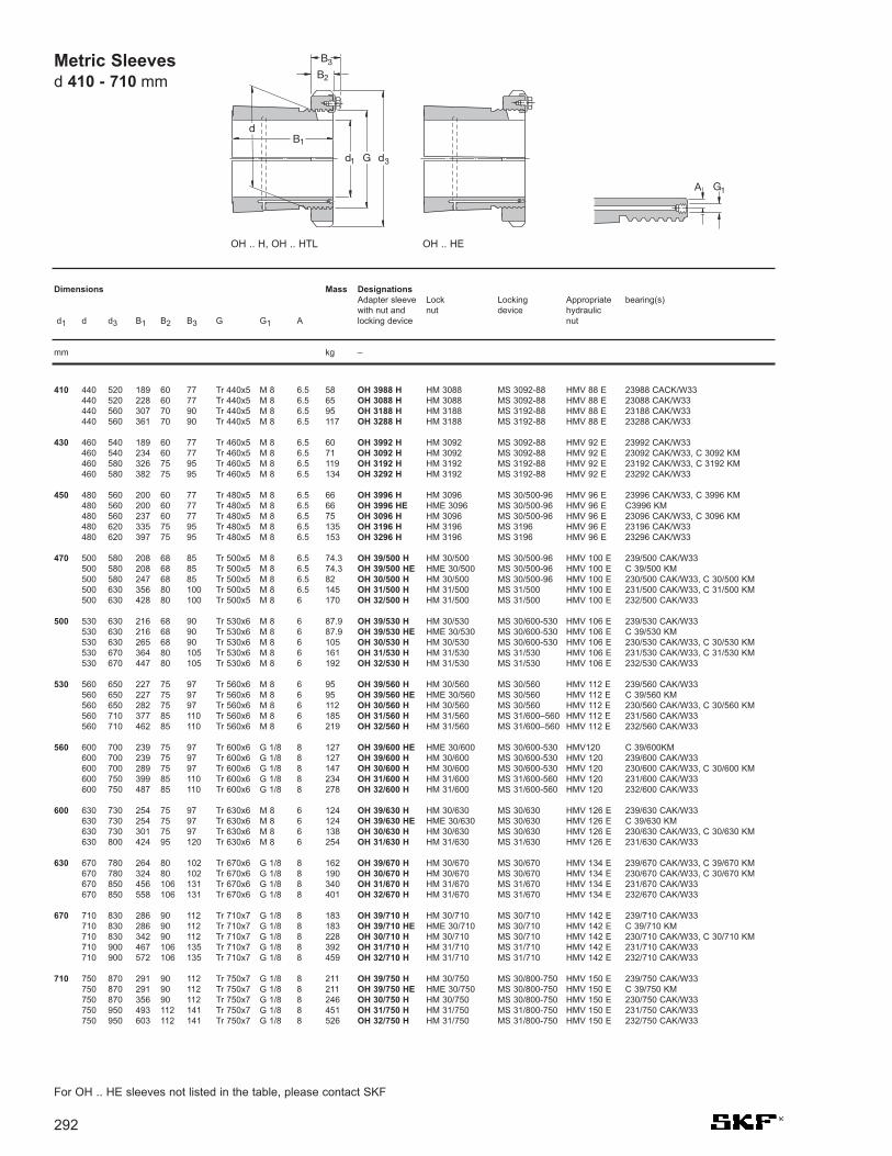
292
Metric Sleeves d 410 - 710 mm
410 440 520 189 60 77 Tr 440x5 M 8 6.5 58 OH 3988 H HM 3088 MS 3092-88 HMV 88 E 23988 CACK/W33440 520 228 60 77 Tr 440x5 M 8 6.5 65 OH 3088 H HM 3088 MS 3092-88 HMV 88 E 23088 CAK/W33440 560 307 70 90 Tr 440x5 M 8 6.5 95 OH 3188 H HM 3188 MS 3192-88 HMV 88 E 23188 CAK/W33440 560 361 70 90 Tr 440x5 M 8 6.5 117 OH 3288 H HM 3188 MS 3192-88 HMV 88 E 23288 CAK/W33
430 460 540 189 60 77 Tr 460x5 M 8 6.5 60 OH 3992 H HM 3092 MS 3092-88 HMV 92 E 23992 CAK/W33460 540 234 60 77 Tr 460x5 M 8 6.5 71 OH 3092 H HM 3092 MS 3092-88 HMV 92 E 23092 CAK/W33, C 3092 KM460 580 326 75 95 Tr 460x5 M 8 6.5 119 OH 3192 H HM 3192 MS 3192-88 HMV 92 E 23192 CAK/W33, C 3192 KM460 580 382 75 95 Tr 460x5 M 8 6.5 134 OH 3292 H HM 3192 MS 3192-88 HMV 92 E 23292 CAK/W33
450 480 560 200 60 77 Tr 480x5 M 8 6.5 66 OH 3996 H HM 3096 MS 30/500-96 HMV 96 E 23996 CAK/W33, C 3996 KM480 560 200 60 77 Tr 480x5 M 8 6.5 66 OH 3996 HE HME 3096 MS 30/500-96 HMV 96 E C3996 KM480 560 237 60 77 Tr 480x5 M 8 6.5 75 OH 3096 H HM 3096 MS 30/500-96 HMV 96 E 23096 CAK/W33, C 3096 KM480 620 335 75 95 Tr 480x5 M 8 6.5 135 OH 3196 H HM 3196 MS 3196 HMV 96 E 23196 CAK/W33480 620 397 75 95 Tr 480x5 M 8 6.5 153 OH 3296 H HM 3196 MS 3196 HMV 96 E 23296 CAK/W33
470 500 580 208 68 85 Tr 500x5 M 8 6.5 74.3 OH 39/500 H HM 30/500 MS 30/500-96 HMV 100 E 239/500 CAK/W33500 580 208 68 85 Tr 500x5 M 8 6.5 74.3 OH 39/500 HE HME 30/500 MS 30/500-96 HMV 100 E C 39/500 KM500 580 247 68 85 Tr 500x5 M 8 6.5 82 OH 30/500 H HM 30/500 MS 30/500-96 HMV 100 E 230/500 CAK/W33, C 30/500 KM500 630 356 80 100 Tr 500x5 M 8 6.5 145 OH 31/500 H HM 31/500 MS 31/500 HMV 100 E 231/500 CAK/W33, C 31/500 KM500 630 428 80 100 Tr 500x5 M 8 6 170 OH 32/500 H HM 31/500 MS 31/500 HMV 100 E 232/500 CAK/W33
500 530 630 216 68 90 Tr 530x6 M 8 6 87.9 OH 39/530 H HM 30/530 MS 30/600-530 HMV 106 E 239/530 CAK/W33530 630 216 68 90 Tr 530x6 M 8 6 87.9 OH 39/530 HE HME 30/530 MS 30/600-530 HMV 106 E C 39/530 KM530 630 265 68 90 Tr 530x6 M 8 6 105 OH 30/530 H HM 30/530 MS 30/600-530 HMV 106 E 230/530 CAK/W33, C 30/530 KM530 670 364 80 105 Tr 530x6 M 8 6 161 OH 31/530 H HM 31/530 MS 31/530 HMV 106 E 231/530 CAK/W33, C 31/530 KM530 670 447 80 105 Tr 530x6 M 8 6 192 OH 32/530 H HM 31/530 MS 31/530 HMV 106 E 232/530 CAK/W33
530 560 650 227 75 97 Tr 560x6 M 8 6 95 OH 39/560 H HM 30/560 MS 30/560 HMV 112 E 239/560 CAK/W33560 650 227 75 97 Tr 560x6 M 8 6 95 OH 39/560 HE HME 30/560 MS 30/560 HMV 112 E C 39/560 KM560 650 282 75 97 Tr 560x6 M 8 6 112 OH 30/560 H HM 30/560 MS 30/560 HMV 112 E 230/560 CAK/W33, C 30/560 KM560 710 377 85 110 Tr 560x6 M 8 6 185 OH 31/560 H HM 31/560 MS 31/600–560 HMV 112 E 231/560 CAK/W33560 710 462 85 110 Tr 560x6 M 8 6 219 OH 32/560 H HM 31/560 MS 31/600–560 HMV 112 E 232/560 CAK/W33
560 600 700 239 75 97 Tr 600x6 G 1/8 8 127 OH 39/600 HE HME 30/600 MS 30/600-530 HMV120 C 39/600KM600 700 239 75 97 Tr 600x6 G 1/8 8 127 OH 39/600 H HM 30/600 MS 30/600-530 HMV 120 239/600 CAK/W33600 700 289 75 97 Tr 600x6 G 1/8 8 147 OH 30/600 H HM 30/600 MS 30/600-530 HMV 120 230/600 CAK/W33, C 30/600 KM600 750 399 85 110 Tr 600x6 G 1/8 8 234 OH 31/600 H HM 31/600 MS 31/600-560 HMV 120 231/600 CAK/W33600 750 487 85 110 Tr 600x6 G 1/8 8 278 OH 32/600 H HM 31/600 MS 31/600-560 HMV 120 232/600 CAK/W33
600 630 730 254 75 97 Tr 630x6 M 8 6 124 OH 39/630 H HM 30/630 MS 30/630 HMV 126 E 239/630 CAK/W33630 730 254 75 97 Tr 630x6 M 8 6 124 OH 39/630 HE HME 30/630 MS 30/630 HMV 126 E C 39/630 KM630 730 301 75 97 Tr 630x6 M 8 6 138 OH 30/630 H HM 30/630 MS 30/630 HMV 126 E 230/630 CAK/W33, C 30/630 KM630 800 424 95 120 Tr 630x6 M 8 6 254 OH 31/630 H HM 31/630 MS 31/630 HMV 126 E 231/630 CAK/W33
630 670 780 264 80 102 Tr 670x6 G 1/8 8 162 OH 39/670 H HM 30/670 MS 30/670 HMV 134 E 239/670 CAK/W33, C 39/670 KM670 780 324 80 102 Tr 670x6 G 1/8 8 190 OH 30/670 H HM 30/670 MS 30/670 HMV 134 E 230/670 CAK/W33, C 30/670 KM670 850 456 106 131 Tr 670x6 G 1/8 8 340 OH 31/670 H HM 31/670 MS 31/670 HMV 134 E 231/670 CAK/W33670 850 558 106 131 Tr 670x6 G 1/8 8 401 OH 32/670 H HM 31/670 MS 31/670 HMV 134 E 232/670 CAK/W33
670 710 830 286 90 112 Tr 710x7 G 1/8 8 183 OH 39/710 H HM 30/710 MS 30/710 HMV 142 E 239/710 CAK/W33710 830 286 90 112 Tr 710x7 G 1/8 8 183 OH 39/710 HE HME 30/710 MS 30/710 HMV 142 E C 39/710 KM710 830 342 90 112 Tr 710x7 G 1/8 8 228 OH 30/710 H HM 30/710 MS 30/710 HMV 142 E 230/710 CAK/W33, C 30/710 KM710 900 467 106 135 Tr 710x7 G 1/8 8 392 OH 31/710 H HM 31/710 MS 31/710 HMV 142 E 231/710 CAK/W33710 900 572 106 135 Tr 710x7 G 1/8 8 459 OH 32/710 H HM 31/710 MS 31/710 HMV 142 E 232/710 CAK/W33
710 750 870 291 90 112 Tr 750x7 G 1/8 8 211 OH 39/750 H HM 30/750 MS 30/800-750 HMV 150 E 239/750 CAK/W33750 870 291 90 112 Tr 750x7 G 1/8 8 211 OH 39/750 HE HME 30/750 MS 30/800-750 HMV 150 E C 39/750 KM750 870 356 90 112 Tr 750x7 G 1/8 8 246 OH 30/750 H HM 30/750 MS 30/800-750 HMV 150 E 230/750 CAK/W33750 950 493 112 141 Tr 750x7 G 1/8 8 451 OH 31/750 H HM 31/750 MS 31/800-750 HMV 150 E 231/750 CAK/W33750 950 603 112 141 Tr 750x7 G 1/8 8 526 OH 32/750 H HM 31/750 MS 31/800-750 HMV 150 E 232/750 CAK/W33
Dimensions Mass DesignationsAdapter sleeve Lock Locking Appropriate bearing(s)with nut and nut device hydraulic
d1 d d3 B1 B2 B3 G G1 A locking device nut
mm kg –
For OH .. HE sleeves not listed in the table, please contact SKF
B2
B3
d1 G d3
dB1
G1A
OH .. H, OH .. HTL OH .. HE

293
750 800 920 303 90 112 Tr 800x7 G 1/8 10 259 OH 39/800 H HM 30/800 MS 30/800-750 HMV 160 E 239/800 CAK/W33800 920 303 90 112 Tr 800x7 G 1/8 10 259 OH 39/800 HE HME 30/800 MS 30/800-750 HMV 160 E C 39/800 KM800 920 366 90 112 Tr 800x7 G 1/8 10 302 OH 30/800 H HM 30/800 MS 30/800-750 HMV 160 E 230/800 CAK/W33800 1 000 505 112 141 Tr 800x7 G 1/8 10 535 OH 31/800 H HM 31/800 MS 31/800-750 HMV 160 E 231/800 CAK/W33
800 850 980 308 90 115 Tr 850x7 G 1/8 10 288 OH 39/850 H HM 30/850 MS 30/900-850 HMV 170 E 239/850 CAK/W33850 980 308 90 115 Tr 850x7 G 1/8 10 288 OH 39/850 HE HME 30/850 MS 30/900-850 HMV 170 E C 39/850 KM850 980 380 90 115 Tr 850x7 G 1/8 10 341 OH 30/850 H HM 30/850 MS 30/900-850 HMV 170 E 230/850 CAK/W33850 1 060 536 118 147 Tr 850x7 G 1/8 10 616 OH 31/850 H HM 31/850 MS 31/850 HMV 170 E 231/850 CAK/W33
850 900 1 030 326 100 125 Tr 900x7 G 1/8 10 330 OH 39/900 H HM 30/900 MS 30/900-850 HMV 180 E 239/900 CAK/W33900 1 030 326 100 125 Tr 900x7 G 1/8 10 330 OH 39/900 HE HME 30/900 MS 30/900-850 HMV 180 E C 39/900 KMB900 1 030 400 100 125 Tr 900x7 G 1/8 10 387 OH 30/900 H HM 30/900 MS 30/900-850 HMV 180 E 230/900 CAK/W33900 1 120 557 125 154 Tr 900x7 G 1/8 10 677 OH 31/900 H HM 31/900 MS 31/900 HMV 180 E 231/900 CAK/W33
900 950 1 080 344 100 125 Tr 950x8 G 1/8 10 363 OH 39/950 H HM 30/950 MS 30/950 HMV 190 E 239/950 CAK/W33950 1 080 420 100 125 Tr 950x8 G 1/8 10 424 OH 30/950 H HM 30/950 MS 30/950 HMV 190 E 230/950 CAK/W33950 1 170 583 125 154 Tr 950x8 G 1/8 10 738 OH 31/950 H HM 31/950 MS 31/950 HMV 190 E 231/950 CAK/W33
950 1 000 1 140 358 100 125 Tr 1000x8 G 1/8 10 407 OH 39/1000 H HM 30/1000 MS 30/1000 HMV 200 E 239/1000 CAK/W331 000 1 140 430 100 125 Tr 1000x8 G 1/8 10 470 OH 30/1000 H HM 30/1000 MS 30/1000 HMV 200 E 230/1000 CAK/W331 000 1 240 609 100 154 Tr 1000x8 G 1/8 10 842 OH 31/1000 H HM 31/1000 MS 31/1000 HMV 200 E 231/1000 CAK/W33
1 000 1 060 1 200 372 100 125 Tr 1060x8 G 1/8 12 490 OH 39/1060 H HM 30/1060 MS 30/1000 HMV 212 E 239/1060 CAK/W331 060 1 200 447 100 125 Tr 1060x8 G 1/8 12 571 OH 30/1060 H HM 30/1060 MS 30/1000 HMV 212 E 230/1060 CAK/W331 060 1 300 622 125 154 Tr 1060x8 G 1/8 12 984 OH 31/1060 H HM 31/1060 MS 31/1000 HMV 212 E 231/1060 CAK/W33
Dimensions Mass DesignationsAdapter sleeve Lock Locking Appropriate bearing(s)with nut and nut device hydraulic
d1 d d3 B1 B2 B3 G G1 A locking device nut
mm kg –
Metric Sleeves d 750 - 1 000 mm
For OH .. HE sleeves not listed in the table, please contact SKF

294
Inch Sleevesd 3/4 - 17/16 in
3/4 19.05 25 38 26 8 M 25x1.5 0.07 HE 205 KM 5 MB 5 - 1205 EK25 38 29 8 M 25x1.5 0.08 HE 305 KM 5 MB 5 - 2205 EK, 1305 EK25 38 29 10.5 M 25x1.5 0.088 HE 305 E KMFE 5 – - C2205 K25 38 35 8 M 25x1.5 0.09 HE 2305 KM 5 MB 5 - 2305 K
7/8 22.225 30 45 27 8 M 30x1.5 0.11 HS 206 KM 6 MB 6 - 1206 EK30 45 31 8 M 30x1.5 0.12 HS 306 KM 6 MB 6 - 2206 EK, 1306 EK
15/16 23.813 30 45 27 8 M 30x1.5 0.1 HA 206 KM 6 MB 6 - 1206 EK30 45 31 8 M 30x1.5 0.12 HA 306 KM 6 MB 6 - 2206 EK30 45 31 10.5 M 30x1.5 0.13 HA 306 E KMFE 6 – - C 2206 K30 45 38 8 M 30x1.5 0.13 HA 2306 KM 6 MB 6 - 2306 K
1 25.4 30 45 27 8 M 30x1.5 0.08 HE 206 KM 6 MB 6 - 1206 EK30 45 31 8 M 30x1.5 0.1 HE 306 KM 6 MB 6 - 2206 EK, 1306 EK30 45 31 10.5 M 30x1.5 0.11 HE 306 E KMFE 6 – - C 2206 K30 45 38 8 M 30x1.5 0.11 HE 2306 KM 6 MB 6 - 2306 K
11/8 28.575 35 52 29 9 M 35x1.5 0.14 HS 207 KM 7 MB 7 - 1207 EK35 52 35 9 M 35x1.5 0.16 HS 307 KM 7 MB 7 - 2207 EK, 1307 EK,
22207 EK35 52 35 11.5 M 35x1.5 0.17 HS 307 E KMFE 7 – - C 2207 K
13/16 30.163 35 52 29 9 M 35x1.5 0.12 HA 207 KM 7 MB 7 - 1207 EK35 52 35 9 M 35x1.5 0.14 HA 307 KM 7 MB 7 - 2207 EK, 1307 EK,
22207 EK35 52 35 11.5 M 35x1.5 0.15 HA 307 E KMFE 7 – - C 2207 K35 52 43 9 M 35x1.5 0.16 HA 2307 KM 7 MB 7 - 2307 EK
11/4 31.75 40 58 31 10 M 40x1.5 0.19 HE 208 KM 8 MB 8 - 1208 EK40 58 36 10 M 40x1.5 0.22 HE 308 KM 8 MB 8 - 2208 EK, 1308 EK,
22208 EK, 21308 CCK40 58 36 13 M 40x1.5 0.19 HE 308 E KMFE 8 – - C 2208 K40 58 46 10 M 40x1.5 0.28 HE 2308 KM 8 MB 8 - 2308 EK, 22308 EK
13/8 34.925 40 58 31 10 M 40x1.5 0.16 HS 208 KM 8 MB 8 - 1208 EK40 58 36 10 M 40x1.5 0.17 HS 308 KM 8 MB 8 - 2208 EK, 1308 EK,
22208 EK, 21308 CCK
17/16 36.512 45 65 33 11 M 45x1.5 0.26 HA 209 KM 9 MB 9 - 1209 EK45 65 39 11 M 45x1.5 0.29 HA 309 KM 9 MB 9 - 2209 EK, 1309 EK,
22209 EK, 21309 CCK45 65 39 13 M 45x1.5 0.31 HA 309 E KMFE 9 – - C 2209 K45 65 50 11 M 45x1.5 0.35 HA 2309 KM 9 MB 9 - 2309 EK, 22309 EK
Dimensions Mass DesignationsAdapter sleeve Lock Locking Appropriate bearing(s)with nut and nut device hydraulic
d1 d d3 B1 B2 G locking device nut
in mm kg –
B2
B1
d1 G dd
3
B2
HA, HE, HS HA .. E, HE .. E, HS .. E

295
11/2 38.1 45 65 33 11 M 45x1.5 0.2 HE 209 KM 9 MB 9 – 1209 EK45 65 39 11 M 45x1.5 0.24 HE 309 KM 9 MB 9 – 2209 EK, 1309 EK,
22209 EK, 21309 CCK45 65 39 13 M 45x1.5 0.26 HE 309 E KMFE 9 – – C 2209 K45 65 50 11 M 45x1.5 0.31 HE 2309 KM 9 MB 9 – 2309 EK, 22309 EK
15/8 41.275 50 70 35 12 M 50x1.5 0.31 HS 210 KM 10 MB 10 HMV 10 E 1210 EK50 70 42 12 M 50x1.5 0.36 HS 310 KM 10 MB 10 HMV 10 E 2210 EK, 1310 EK,
22210 EK, 21310 CCK50 70 55 12 M 50x1.5 0.4 HS 2310 KM 10 MB 10 HMV 10 E 2310 EK, 22310 EK
111/16 42.863 50 70 35 12 M 50x1.5 0.28 HA 210 KM 10 MB 10 HMV 10 E 1210 EK50 70 42 12 M 50x1.5 0.32 HA 310 KM 10 MB 10 HMV 10 E 2210 EK, 1310 EK,
22210 EK, 21310 CCK50 70 42 14 M 50x1.5 0.32 HA 310 E KMFE 10 – HMV 10 E C 2210 K50 70 55 12 M 50x1.5 0.4 HA 2310 KM 10 MB 10 HMV 10 E 2310 EK, 22310 EK
13/4 44.45 50 70 35 12 M 50x1.5 0.26 HE 210 KM 10 MB 10 HMV 10 E 1210 EK50 70 42 12 M 50x1.5 0.29 HE 310 KM 10 MB 10 HMV 10 E 2210 EK, 1310 EK,
22210 EK, 21310 CCK50 70 42 14 M 50x1.5 0.29 HE 310 E KMFE 10 – HMV 10 E C 2210 K50 70 55 12 M 50x1.5 0.36 HE 2310 KM 10 MB 10 HMV 10 E 2310 EK, 22310 EK
17/8 47.625 55 75 37 12.5 M 55x2 0.33 HS 211 KM 11 MB 11 HMV 11 E 1211 EK55 75 45 12.5 M 55x2 0.38 HS 311 KM 11 MB 11 HMV 11 E 2211 EK, 1311 EK,
22211 EK, 21311 CCK
115/16 49.213 55 75 37 12.5 M 55x2 0.3 HA 211 KM 11 MB 11 HMV 11 E 1211 EK55 75 45 12.5 M 55x2 0.34 HA 311 KM 11 MB 11 HMV 11 E 2211 EK, 1311 EK,
22211 EK, 21311 CCK55 75 45 14 M 55x2 0.35 HA 311 E KMFE 11 – HMV 11 E C 2211 K55 75 59 12.5 M 55x2 0.42 HA 2311 KM 11 MB 11 HMV 11 E 2311 K, 22311 EK
2 50.8 55 75 37 12.5 W 55x1/19 0,26 HE 211 B HM 11 MB 11 – 1211 EK55 75 45 12.5 W 55x1/19 0,29 HE 311 B HM 11 MB 11 – 2211 EK. 1311 EK.
22211 EK. 21311 CCK55 75 45 14 W 55x1/19 0,3 HE 311 BE KMFE 11 B – – C 2211 K55 75 59 12.5 W 55x1/19 0,36 HE 2311 B HM 11 MB 11 – 2311 K, 22311 EK
21/8 53.975 60 80 38 13 M 60x2 0.35 HS 212 KM 12 MB 12 HMV 12 E 1212 EK60 80 47 13 M 60x2 0.4 HS 312 KM 12 MB 12 HMV 12 E 2212 EK, 1312 EK,
22212 EK, 21312 CCK60 80 47 14 M 60x2 0.41 HS 312 E KMFE 12 – HMV 12 E C 2212 K60 80 62 13 M 60x2 0.49 HS 2312 KM 12 MB 12 HMV 12 E 2312 K, 22312 EK
Inch Sleeves d 11/2 - 21/8 in
Dimensions Mass DesignationsAdapter sleeve Lock Locking Appropriate bearing(s)with nut and nut device hydraulic
d1 d d3 B1 B2 G locking device nut
in mm kg –

296
Inch Sleeves d 23/16 - 211/16 in
23/16 55.563 65 85 40 14 M 65x2 0.49 HA 213 KM 13 MB 13 HMV 13 E 1213 K65 85 50 14 M 65x2 0.58 HA 313 KM 13 MB 13 HMV 13 E 2213 EK, 1313 EK,
22213 EK, 21313 CCK65 85 50 15 M 65x2 0.59 HA 313 E KMFE 13 – HMV 13 E C 2213 K65 85 65 14 M 65x2 0.75 HA 2313 KM 13 MB 13 HMV 13 E 2313 K, 22313 EK
21/4 57.15 65 85 40 14 M 65x2 0.44 HE 213 KM 13 MB 13 HMV 13 E 1213 EK65 85 50 14 M 65x2 0.52 HE 313 KM 13 MB 13 HMV 13 E 2213 EK, 1313 EK,
22213 EK, 21313 CCK65 85 50 15 M 65x2 0.53 HE 313 E KMFE 13 – HMV 13 E C 2213 E65 85 65 14 M 65x2 0.65 HE 2313 KM 13 MB 13 HMV 13 E 2313 K, 22313 EK
23/8 60.325 65 85 40 14 M 65x2 0.44 HS 213 KM 13 MB 13 HMV 13 E 1213 EK65 85 50 14 M 65x2 0.71 HS 313 KM 13 MB 13 HMV 13 E 2213 EK, 1313 EK,
22213 EK, 21313 CCK65 85 65 14 M 65x2 0.8 HS 2313 KM 13 MB 13 HMV 13 E 2313 K, 22313 EK
27/16 61.913 75 98 43 15 M 75x2 0.75 HA 215 KM 15 MB 15 HMV 15 E 1215 K75 98 55 15 M 75x2 0.91 HA 315 KM 15 MB 15 HMV 15 E 2215 EK, 1315 EK,
22215 EK, 21315 CCK75 98 55 16 M 75x2 0.93 HA 315 E KMFE 15 – HMV 15 E C 2215 K75 98 73 15 M 75x2 1.15 HA 2315 KM 15 MB 15 HMV 15 E 2315 K, 22315 EK,
C 2315 K
21/2 63.5 75 98 43 15 M 75x2 0.7 HE 215 KM 15 MB 15 HMV 15 E 1215 K75 98 55 15 M 75x2 0.85 HE 315 KM 15 MB 15 HMV 15 E 2215 K, 1315 K,
22215 EK, 21315 CCK75 98 55 16 M 75x2 0.87 HE 315 E KMFE 15 – HMV 15 E C 2215 K75 98 73 15 M 75x2 1.09 HE 2315 KM 15 MB 15 HMV 15 E 2315 K, 22315 EK,
C 2315 K, C 2315 K
25/8 66.675 75 98 43 15 M 75x2 0.7 HS 215 KM 15 MB 15 HMV 15 E 1215 K75 98 55 15 M 75x2 0.71 HS 315 KM 15 MB 15 HMV 15 E 2215 EK, 1315 EK,
22215 EK, 21315 CCK75 98 73 15 M 75x2 0.9 HS 2315 KM 15 MB 15 HMV 15 E 2315 K, 22315 EK,
C 2315 K
211/16 68.263 80 105 46 17 M 80x2 0.87 HA 216 KM 16 MB 16 HMV 16 E 1216 K80 105 59 17 M 80x2 1.05 HA 316 KM 16 MB 16 HMV 16 E 2216 EK, 1316 EK,
22216 EK, 21316 CCK80 105 59 18 M 80x2 1.06 HA 316 E KMFE 16 – HMV 16 E C 2216 K80 105 78 17 M 80x2 1.3 HA 2316 KM 16 MB 16 HMV 16 E 2316 K, 22316 K,
C 2316 K
B2
B1
d1 G dd
3
B2
Dimensions Mass DesignationsAdapter sleeve Lock Locking Appropriate bearing(s)with nut and nut device hydraulic
d1 d d3 B1 B2 G locking device nut
in mm kg –
HA, HE, HS HA .. E, HE .. E,

297
23/4 69.85 80 105 46 17 M 80x2 0.81 HE 216 KM 16 MB 16 HMV 16 E 1216 K80 105 59 17 M 80x2 0.97 HE 316 KM 16 MB 16 HMV 16 E 2216 EK, 1316 K,
22216 EK, 21316 CCK80 105 59 18 M 80x2 0.98 HE 316 E KMFE 16 – HMV 16 E C 2216 K80 105 78 17 M 80x2 1.2 HE 2316 KM 16 MB 16 HMV 16 E 2316 K, 22316 EK,
C 2316 K
215/16 74.613 85 110 50 18 M 85x2 0.94 HA 217 KM 17 MB 17 HMV 17 E 1217 K85 110 63 18 M 85x2 1.1 HA 317 KM 17 MB 17 HMV 17 E 2217 EK, 1317 K,
22217 EK, 21317 CCK85 110 63 19 M 85x2 1.19 HA 317 E KMFE 17 – HMV 17 E C 2217 E85 110 82 18 M 85x2 1.4 HA 2317 KM 17 MB 17 HMV 17 E 2317 K, 22317 EK,
C 2317 K
3 76.2 85 110 50 18 M 85x2 0.87 HE 217 KM 17 MB 17 HMV 17 E 1217 K85 110 63 18 M 85x2 1 HE 317 KM 17 MB 17 HMV 17 E 2217 K, 1317 K,
22217 EK, 21317 CCK85 110 63 19 M 85x2 0.99 HE 317 E KMFE 17 – HMV 17 E C 2217 K85 110 82 18 M 85x2 1.3 HE 2317 KM 17 MB 17 HMV 17 E 2317 K, 22317 EK,
C 2317 K
33/16 80.963 90 120 52 18 M 90x2 1.05 HA 218 KM 18 MB 18 HMV 18 E 1218 K90 120 65 18 M 90x2 1.25 HA 318 KM 18 MB 18 HMV 18 E 2218 K, 1318 K,
22218 EK, 21318 CCK90 120 65 19 M 90x2 1.26 HA 318 E KMFE 18 – HMV 18 E C 2218 K90 120 86 18 M 90x2 1.5 HA 2318 KM 18 MB 18 HMV 18 E 2318 K, 23218-
CCK/W33, 22318 EK, C 2318 K
31/4 82.55 90 120 52 18 M 90x2 0.97 HE 218 KM 18 MB 18 HMV 18 E 1218 K90 120 65 18 M 90x2 1.1 HE 318 KM 18 MB 18 HMV 18 E 2218 K, 1318 K,
22218 EK, 21318 CCK90 120 65 19 M 90x2 1.11 HE 318 E KMFE 18 – HMV 18 E C 2218 K90 120 86 18 M 90x2 1.4 HE 2318 KM 18 MB 18 HMV 18 E 2318 K, 23218-
CCK/W33, 22318 EK, C2318 K
95 125 55 19 M 95x2 1.35 HE 219 KM 19 MB 19 HMV 19 E 1219 K95 125 68 19 M 95x2 1.6 HE 319 KM 19 MB 19 HMV 19 E 2219 K, 1319 K,
22219 EK, 21319 CCK95 125 68 20 M 95x2 1.61 HE 319 E KMFE 19 – HMV 19 E C 2219 K95 125 90 19 M 95x2 2 HE 2319 KM 19 MB 19 HMV 19 E 2319 K, 22319 EK,
C 2319 K
Inch Sleeves d 23/4 - 31/4 in
Dimensions Mass DesignationsAdapter sleeve Lock Locking Appropriate bearing(s)with nut and nut device hydraulic
d1 d d3 B1 B2 G locking device nut
in mm kg –

298
Inch Sleeves d 37/16 - 41/4 in
37/16 87.313 100 130 58 20 M 100x2 1.55 HA 220 KM 20 MB 20 HMV 20 E 1220 K100 130 71 20 M 100x2 1.8 HA 320 KM 20 MB 20 HMV 20 E 2220 K, 1320 K,
22220 EK, 21320 CCK100 130 71 21 M 100x2 1.75 HA 320 E KMFE 20 – HMV 20 E C 2220 K100 130 97 20 M 100x2 2.35 HA 2320 KM 20 MB 20 HMV 20 E 2320 K, 23220-
CCK/W33, 22320 EK, C2320 K
31/2 88.9 100 130 58 20 M 100x2 1.45 HE 220 KM 20 MB 20 HMV 20 E 1220 K100 130 71 20 M 100x2 1.75 HE 320 KM 20 MB 20 HMV 20 E 2220 K, 1320 K,
22220 EK, 21320 CCK100 130 71 21 M 100x2 1.7 HE 320 E KMFE 20 – HMV 20 E C 2220 K100 130 76 20 M 100x2 1.8 HE 3120 KM 20 MB 20 HMV 20 E 23120 CCK/W33100 130 97 20 M 100x2 2.2 HE 2320 KM 20 MB 20 HMV 20 E 2320 K, 23220-
CCK/W33, 22320 EK, C2320 K
315/16 See metric sleeves for d1 = 100mm
4 101.6 110 145 63 21 M 110x2 1.65 HE 222 KM 22 MB 22 HMV 22 E 1222 K110 145 77 21 M 110x2 1.9 HE 322 KM 22 MB 22 HMV 22 E 2222 K, 1322 K,
23022 CCK, 22222 EK,21322 CCK
110 145 77 21.5 M 110x2 1.85 HE 322 E KMFE 22 – HMV 22 E C 2222 K110 145 81 21 M 110x2 2.25 HE 3122 KM 22 MB 22 HMV 22 E 23122 CCK/W33110 145 105 21 M 110x2 2.4 HE 2322 KM 22 MB 22 HMV 22 E 2322 K, 23222-
CCK/W33, 22322 EK
43/16 106.363 120 145 72 22 M 120x2 2.25 HA 3024 KML 24 MBL 24 HMV 24 E 1224 K, 23024-CCK/W33
120 155 72 26 M 120x2 2.32 HA 3024 E KMFE 24 – HMV 24 E C 3024 K120 155 88 22 M 120x2 2.9 HA 3124 KM 24 MB 24 HMV 24 E 2224 K, 23124-
CCK/W33120 145 88 22 M 120x2 2.6 HA 3124 L KML 24 MBL 24 HMV 24 E C 2224 K120 155 112 22 M 120x2 3.6 HA 2324 KM 24 MB 24 HMV 24 E 23224 CCK/W33,
22324 CCK/W33120 145 112 22 M 120x2 3.3 HA 2324 L KML 24 MBL 24 HMV 24 E C 3224 K
41/4 107.95 120 145 72 22 M 120x2 2 HE 3024 KML 24 MBL 24 HMV 24 E 1224 K, 23024-CCK/W33, C 3024 KV
120 155 72 26 M 120x2 2.7 HE 3024 E KMFE 24 – HMV 24 E C 3024 K120 155 88 22 M 120x2 2.8 HE 3124 KM 24 MB 24 HMV 24 E 23124 CCK/W33.
22224 EK120 155 112 22 M 120x2 3.35 HE 2324 KM 24 MB 24 HMV 24 E 23224 CCK/W33,
22324 CCK/W33120 145 112 22 M 120x2 3.05 HE 2324 L KML 24 MBL 24 HMV 24 E C 3224 K
B2
B1
d1 G dd
3
B2
Dimensions Mass DesignationsAdapter sleeve Lock Locking Appropriate bearing(s)with nut and nut device hydraulic
d1 d d3 B1 B2 G locking device nut
in mm kg –
HA, HA .. L, HE, HE ..L HA .. E, HE .. E,

299
47/16 112.713 130 155 80 23 M 130x2 3.05 HA 3026 KML 26 MBL 26 HMV 26 E 23026 CCK/W33130 165 92 23 M 130x2 3.75 HA 3126 KM 26 MB 26 HMV 26 E 23126 CCK/W33,
22226 EK130 155 92 23 M 130x2 3.55 HA 3126 L KML 26 MBL 26 HMV 26 E C 2226 K130 165 92 28 M 130x2 3.77 HA 3126 E KMFE 26 – HMV 26 E C 2226 K130 165 121 23 M 130x2 4.74 HA 2326 KM 26 MB 26 HMV 26 E 23226 CCK/W33,
22326 CCK/W33, C 2326 K
41/2 114.3 130 155 80 23 M 130x2 2.9 HE 3026 KML 26 MBL 26 HMV 26 E 23026 CCK/W33, C 3026 K
130 165 92 23 M 130x2 3.6 HE 3126 KM 26 MB 26 HMV 26 E 23126 CCK/W33,22226 EK
130 155 92 23 M 130x2 3.4 HE 3126 L KML 26 MBL 26 HMV 26 E C 2226 K130 165 121 23 M 130x2 4.55 HE 2326 KM 26 MB 26 HMV 26 E 23226 CCK/W33,
22326 CCK/W33, C2326 K
415/16 125.413 140 165 82 24 M 140x2 3 HA 3028 KML 28 MBL 28 HMV 28 E 23028 CCK/W33140 180 97 24 M 140x2 4.1 HA 3128 KM 28 MB 28 HMV 28 E 23128 CCK/W33,
22228 CCK/W33140 165 97 24 M 140x2 4.6 HA 3128 L KML 28 MBL 28 HMV 28 E C 2228 K140 180 131 24 M 140x2 5.3 HA 2328 KM 28 MB 28 HMV 28 E 23228 CCK/W33,
22328 CCK/W33
5 127 140 165 82 24 M 140x2 2.8 HE 3028 KML 28 MBL 28 HMV 28 E 23028 CCK/W33140 180 97 24 M 140x2 3.8 HE 3128 KM 28 MB 28 HMV 28 E 23128 CCK/W33,
22228 CCK/W33140 165 97 24 M 140x2 3.3 HE 3128 L KML 28 MBL 28 HMV 28 E C 2228 K140 180 131 24 M 140x2 5 HE 2328 KM 28 MB 28 HMV 28 E 23228 CCK/W33,
22328 CCK/W33
53/16 131.763 150 180 87 26 M 150x2 4.2 HA 3030 KML 30 MBL 30 HMV 30 E 23030 CCK/W33150 195 111 26 M 150x2 5.8 HA 3130 KM 30 MB 30 HMV 30 E 23130 CCK/W33,
22230 CCK/W33150 180 111 26 M 150x2 5.3 HA 3130 L KML 30 MBL 30 HMV 30 E C 2230 K150 195 139 26 M 150x2 7.1 HA 2330 KM 30 MB 30 HMV 30 E 23230 CCK/W33,
22330 CCK/W33
51/4 133.35 150 180 87 26 M 150x2 4 HE 3030 KML 30 MBL 30 HMV 30 E 23030 CCK/W33150 195 111 26 M 150x2 5.5 HE 3130 KM 30 MB 30 HMV 30 E 23130 CCK/W33,
22230 CCK/W33150 180 111 26 M 150x2 5 HE 3130 L KML 30 MBL 30 HMV 30 E C 2230 K150 195 139 26 M 150x2 6.8 HE 2330 KM 30 MB 30 HMV 30 E 23230 CCK/W33,
22330 CCK/W33
Inch Sleeves d 47/16 - 51/4 in
Dimensions Mass DesignationsAdapter sleeve Lock Locking Appropriate bearing(s)with nut and nut device hydraulic
d1 d d3 B1 B2 G locking device nut
in mm kg –
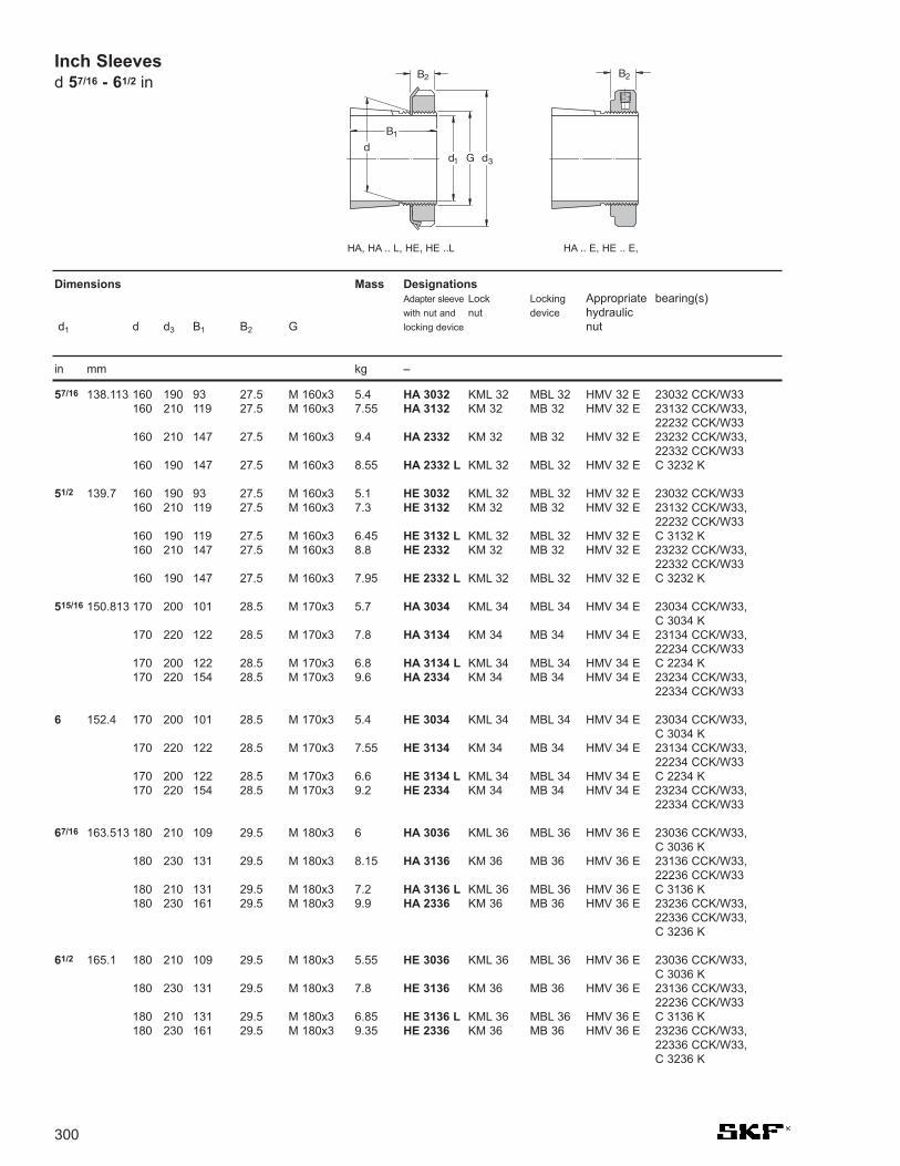
300
Inch Sleeves d 57/16 - 61/2 in
57/16 138.113 160 190 93 27.5 M 160x3 5.4 HA 3032 KML 32 MBL 32 HMV 32 E 23032 CCK/W33160 210 119 27.5 M 160x3 7.55 HA 3132 KM 32 MB 32 HMV 32 E 23132 CCK/W33,
22232 CCK/W33160 210 147 27.5 M 160x3 9.4 HA 2332 KM 32 MB 32 HMV 32 E 23232 CCK/W33,
22332 CCK/W33160 190 147 27.5 M 160x3 8.55 HA 2332 L KML 32 MBL 32 HMV 32 E C 3232 K
51/2 139.7 160 190 93 27.5 M 160x3 5.1 HE 3032 KML 32 MBL 32 HMV 32 E 23032 CCK/W33160 210 119 27.5 M 160x3 7.3 HE 3132 KM 32 MB 32 HMV 32 E 23132 CCK/W33,
22232 CCK/W33160 190 119 27.5 M 160x3 6.45 HE 3132 L KML 32 MBL 32 HMV 32 E C 3132 K160 210 147 27.5 M 160x3 8.8 HE 2332 KM 32 MB 32 HMV 32 E 23232 CCK/W33,
22332 CCK/W33160 190 147 27.5 M 160x3 7.95 HE 2332 L KML 32 MBL 32 HMV 32 E C 3232 K
515/16 150.813 170 200 101 28.5 M 170x3 5.7 HA 3034 KML 34 MBL 34 HMV 34 E 23034 CCK/W33, C 3034 K
170 220 122 28.5 M 170x3 7.8 HA 3134 KM 34 MB 34 HMV 34 E 23134 CCK/W33, 22234 CCK/W33
170 200 122 28.5 M 170x3 6.8 HA 3134 L KML 34 MBL 34 HMV 34 E C 2234 K170 220 154 28.5 M 170x3 9.6 HA 2334 KM 34 MB 34 HMV 34 E 23234 CCK/W33,
22334 CCK/W33
6 152.4 170 200 101 28.5 M 170x3 5.4 HE 3034 KML 34 MBL 34 HMV 34 E 23034 CCK/W33, C 3034 K
170 220 122 28.5 M 170x3 7.55 HE 3134 KM 34 MB 34 HMV 34 E 23134 CCK/W33, 22234 CCK/W33
170 200 122 28.5 M 170x3 6.6 HE 3134 L KML 34 MBL 34 HMV 34 E C 2234 K170 220 154 28.5 M 170x3 9.2 HE 2334 KM 34 MB 34 HMV 34 E 23234 CCK/W33,
22334 CCK/W33
67/16 163.513 180 210 109 29.5 M 180x3 6 HA 3036 KML 36 MBL 36 HMV 36 E 23036 CCK/W33, C 3036 K
180 230 131 29.5 M 180x3 8.15 HA 3136 KM 36 MB 36 HMV 36 E 23136 CCK/W33, 22236 CCK/W33
180 210 131 29.5 M 180x3 7.2 HA 3136 L KML 36 MBL 36 HMV 36 E C 3136 K180 230 161 29.5 M 180x3 9.9 HA 2336 KM 36 MB 36 HMV 36 E 23236 CCK/W33,
22336 CCK/W33, C 3236 K
61/2 165.1 180 210 109 29.5 M 180x3 5.55 HE 3036 KML 36 MBL 36 HMV 36 E 23036 CCK/W33, C 3036 K
180 230 131 29.5 M 180x3 7.8 HE 3136 KM 36 MB 36 HMV 36 E 23136 CCK/W33, 22236 CCK/W33
180 210 131 29.5 M 180x3 6.85 HE 3136 L KML 36 MBL 36 HMV 36 E C 3136 K180 230 161 29.5 M 180x3 9.35 HE 2336 KM 36 MB 36 HMV 36 E 23236 CCK/W33,
22336 CCK/W33, C 3236 K
Dimensions Mass DesignationsAdapter sleeve Lock Locking Appropriate bearing(s)with nut and nut device hydraulic
d1 d d3 B1 B2 G locking device nut
in mm kg –
B2
B1
d1 G dd
3
B2
HA, HA .. L, HE, HE ..L HA .. E, HE .. E,

301
63/4 171.45 190 220 112 30.5 M 190x3 7.2 HE 3038 KML 38 MBL 38 HMV 38 E 23038 CCK/W33, C3038 K
190 240 141 30.5 M 190x3 10.2 HE 3138 KM 38 MB 38 HMV 38 E 23138 CCK/W33, 22238 CCK/W33
190 240 169 30.5 M 190x3 11.7 HE 2338 KM 38 MB 38 HMV 38 E 23238 CCK/W33, 22338 CCK/W33
615/16 176.213 190 220 112 30.5 M 190x3 5.8 HA 3038 KML 38 MBL 38 HMV 38 E 23038 CCK/W33, C 3038 K
190 240 141 30.5 M 190x3 8.5 HA 3138 KM 38 MB 38 HMV 38 E 23138 CCK/W33, 22238 CCK/W33
190 240 169 30.5 M 190x3 10 HA 2338 KM 38 MB 38 HMV 38 E 23238 CCK/W33, 22338 CCK/W33
7 177.8 200 240 120 31.5 M 200x3 9.35 HE 3040 KML 40 MBL 40 HMV 40 E 23040 CCK/W33, C 3040 K
200 250 150 31.5 M 200x3 12.3 HE 3140 KM 40 MB 40 HMV 40 E 23140 CCK/W33, 22240 CCK/W33, C 3140 K
200 250 176 31.5 M 200x3 14.2 HE 2340 KM 40 MB 40 HMV 40 E 23240 CCK/W33, 22340 CCK/W33
73/16 182.563 200 240 120 31.5 M 200x3 8.25 HA 3040 KML 40 MBL 40 HMV 40 E 23040 CCK/W33, C 3040 K
200 250 150 31.5 M 200x3 11.2 HA 3140 KM 40 MB 40 HMV 40 E 23140 CCK/W33, 22240 CCK/W33, C 3140 K
Inch Sleeves d 63/4 - 73/16 in
Dimensions Mass DesignationsAdapter sleeve Lock Locking Appropriate bearing(s)with nut and nut device hydraulic
d1 d d3 B1 B2 G locking device nut
in mm kg –

302
Adapter sleeves with inch dimensions d 3/4 - 21/16 in
3/4 25 19/16 1.269 0.456 0.969 32 0.10 SNW 5 x 3/4 N05 W05 1205 EK
15/16 30 13/4 1.353 0.456 1.173 18 0.10 SNW 6 x 15/16 N06 W06 1206 EK, 1306 EK
1 30 13/4 1.353 0.456 1.173 18 0.10 SNW 6 x 1 N06 W06 1206 EK, 1306 EK
11/8 35 21/16 1.459 0.487 1.376 18 0.16 SNW 7 x 11/8 N07 W 07 1207 EK, 1307 EK, 22207 EK
13/16 35 21/16 1.459 0.487 1.376 18 0.16 SNW 7 x 13/16 N07 W07 1207 EK, 1307 EK, 22207 EK
11/4 35 21/16 1.459 0.487 1.376 18 0.16 SNW 7 x 11/4 N07 W07 1207 EK, 1307 EK, 22207 EK40 21/4 1.504 0.495 1.563 18 0.19 SNW 8 x 11/4 N08 W08 1208 EK, 1308 EK, 22208 EK
13/8 40 21/4 1.504 0.495 1.563 18 0.19 SNW 8 x 13/8 N08 W08 1208 EK, 1308 EK, 22208 EK45 217/32 1.584 0.495 1.767 18 0.28 SNW 9 x 13/8 N09 W09 1209 EK, 1309 EK, 22209 EK, 21309 EK
15/16 40 21/4 1.504 0.495 1.563 18 0.19 SNW 8 x 15/16 N08 W08 1208 EK, 1308 EK, 22208 EK45 217/32 1.584 0.495 1.767 18 0.28 SNW 9 x 15/16 N09 W09 1209 EK, 1309 EK, 22209 EK, 21309 EK
17/16 45 217/32 1.584 0.495 1.767 18 0.28 SNW 9 x 17/16 N09 W09 1209 EK, 1309 EK, 22209 EK, 21309 EK45 217/32 2.133 0.495 1.767 18 0.32 SNW 109 x 17/16 N09 W09 2309 EK, 22309 EK
11/2 45 217/32 2.133 0.495 1.767 18 0.32 SNW 109 x 11/2 N09 W09 2309 EK, 22309 EK
15/8 50 211/16 1.765 0.558 1.967 18 0.33 SNW 10 x 15/8 N10 W10 1210 EK, 1310 EK, 22210 EK, 21310 CCK
111/16 50 211/16 1.765 0.558 1.967 18 0.33 SNW 10 x 111/16 N10 W10 1210 EK, 1310 EK, 22210 EK, 21310 CCK50 211/16 2.394 0.558 1.967 18 0.39 SNW 110 x 111/16 N10 W10 2310 EK, 22310 EK
13/4 50 211/16 1.765 0.558 1.967 18 0.33 SNW 10 x 13/4 N10 W10 1210 EK, 1310 EK, 22210 EK, 21310 CCK55 231/32 1.845 0.563 2.157 18 0.36 SNW 11 x 13/4 N11 W11 1211 EK, 1311 EK, 22211 EK, 21311 EK
113/16 55 231/32 1.845 0.563 2.157 18 0.36 SNW 11 x 113/16 N11 W11 1211 EK, 1311 EK, 22211 EK, 21311 EK
17/8 55 231/32 1.845 0.563 2.157 18 0.36 SNW 11 x 17/8 N11 W11 1211 EK, 1311 EK, 22211 EK, 21311 EK
115/16 55 231/32 1.845 0.563 2.157 18 0.36 SNW 11 x 115/16 N11 W11 1211 EK, 1311 EK, 22211 EK, 21311 EK55 231/32 2.516 0.563 2.157 18 0.43 SNW 111 x 115/16 N11 W11 2311 K, 22311 EK
2 55 231/32 1.845 0.563 2.157 18 0.36 SNW 11 x 2 N11 W11 1211 EK, 1311 EK, 22211 EK, 21311 EK55 231/32 2.516 0.563 2.157 18 0.43 SNW 111 x 2 N11 W11 2311 K, 22311 EK65 33/8 2.100 0.625 2.548 18 0.64 SNW 13 x 2 N13 W13 1213 EK, 1313 EK, 22213 EK
21/16 60 35/32 2.659 0.594 2.360 18 0.73 SNW 112 x 21/16 N12 W12 2312 K, 22312 EK
Dimensions Mass Designation Locknut Wshr. Appropriatebearings
d1 d d3 B1 B2 G nom. T.P.I.
in. mm in. kg
Threads: American National Form NS Class 3
* For air handling units, H sleeves should be used.
B2
B1
d1 G dd
3

303
23/16 65 33/8 2.100 0.625 2.548 18 0.64 SNW 13 x 23/16 N13 W13 1213 EK, 1313EK, 22213 EK,65 33/8 2.771 0.625 2.548 18 0.79 SNW 113 x 23/16 N13 W13 2313 K, 22313 EK
21/4 65 33/8 2.100 0.625 2.548 18 0.64 SNW 13 x 21/4 N13 W13 1213 EK,1313 EK,22213 EK65 33/8 2.771 0.625 2.548 18 0.79 SNW 113 x 21/4 N13 W13 2313 K, 22313 EK
25/16 65 33/8 2.100 0.625 2.548 18 0.64 SNW 13 x 25/16 N13 W13 1213 EK, 1313EK, 22213 EK,
23/8 75 37/8 2.296 0.665 2.933 12 1.00 SNW 15 x 23/8 AN15 W15 1215 K, 1315 K, 22215 EK
27/16 75 37/8 2.296 0.665 2.933 12 1.00 SNW 15 x 27/16 AN15 W15 1215 K, 1315 K, 22215 EK75 37/8 3.084 0.665 2.933 12 1.35 SNW 115 x 27/16 AN15 W15 2315 K, 22315 EK
211/16 80 45/32 2.376 0.665 3.137 12 1.10 SNW 16 x 211/16 AN16 W16 1216 K, 1316 K, 22216 EK80 45/32 3.204 0.665 3.137 12 1.45 SNW 116 x 211/16 AN16 W16 2316 K, 22316 EK
23/4 80 45/32 2.376 0.665 3.137 12 1.10 SNW 16 x 23/4 AN16 W16 1216 K, 1316 K, 22216 EK
215/16 85 413/32 2.486 0.697 3.340 12 1.30 SNW 17 x 215/16 AN17 W17 1217 K, 1317 K, 22217 EK85 413/32 3.312 0.697 3.340 12 1.55 SNW 117 x 215/16 AN17 W17 2317 K, 22317 EK
3 85 413/32 2.486 0.697 3.340 12 1.30 SNW 17 x 3 AN17 W17 1217 K, 1317 K, 22217 EK85 413/32 3.312 0.697 3.340 12 1.55 SNW 117 x 3 AN17 W17 2317 K, 22317 EK
33/16 90 421/32 2.646 0.782 3.527 12 1.40 SNW 18 x 33/16 AN18 W18 HMVC 18 1218 K, 1318 K, 22218 EK90 421/32 3.553 0.782 3.527 12 1.80 SNW 118 x 33/16 AN18 W18 HMVC 18 2318 K, 23218 CCK/W33, 22318 EK
31/4 90 421/32 2.646 0.782 3.527 12 1.40 SNW 18 x 31/4 AN18 W18 HMVC 18 1218 K, 1318 K, 22218 EK
35/16 95 415/16 2.760 0.813 3.730 12 1.85 SNW 19 x 35/16 AN19 W19 HMVC19 1219 K, 1319 K, 22219 EK95 415/16 3.702 0.813 3.730 12 2.20 SNW 119 x 35/16 AN19 W19 HMVC19 23219 CCK/W33, 22319 EK
37/16 100 53/16 2.869 0.844 3.918 12 2.00 SNW 20 x 37/16 AN20 W20 HMVC20 1220 K, 1320 K, 22220 EK100 53/16 3.971 0.844 3.918 12 2.85 SNW 120 x 37/16 AN20 W20 HMVC20 23220 CCK/W33, 22320EK
31/2 100 53/16 2.869 0.844 3.918 12 2.00 SNW 20 x 31/2 AN20 W20 HMVC20 1220 K, 1320 K, 22220 EK100 53/16 3.971 0.844 3.918 12 2.85 SNW 120 x 31/2 AN20 W20 HMVC20 23220 CCK/W33, 22320EK
311/16 105 57/16 2.987 0.844 4.122 12 2.05 SNW 21 x 311/16 AN21 W21 1321 K110 523/32 3.206 0.906 4.325 12 2.25 SNW 22 x 311/16 AN22 W22 HMVC22 1222 K, 1322 K, 22222 EK
315/16 110 523/32 3.206 0.906 4.325 12 2.25 SNW 22 x 315/16 AN22 W22 HMVC22 1222 K, 1322 K, 22222 EK110 523/32 4.348 0.906 4.325 12 2.95 SNW 122 x 315/16 AN22 W22 HMVC22 23222 CCK/W33, 22322 EK
Dimensions Mass Designation Locknut Washer Appropriate Appropriatehydraulic nut bearings
d1 d d3 B1 B2 G nom. T.P.I.
in. mm in. kg
Adapter sleeves with inch dimensionsd 23/16 - 315/16 in
Threads: American National Form NS Class 3

304
4 110 523/32 3.206 0.906 4.325 12 2.25 SNW 22 x 4 AN22 W22 HMVC 22 1222K, 1322K, 22222EK
43/16 120 511/16 2.947 0.938 4.716 12 2.80 SNW 3024 x 43/16 N024 W024 HMVC 24 23024 CCK/W33511/16 3.466 0.938 4.716 12 2.65 SNW 3124 x 43/16 NO24 W024 HMVC 24 23124 CCK/W3361/8 3.466 0.938 4.716 12 3.00 SNW 24 x 43/16 AN24 W24 HMVC 24 22224 EK61/8 4.648 0.938 4.716 12 3.55 SNW 124 x 43/16 AN24 W24 HMVC 24 23224 CCK/W33,
22324 CCK/W33
41/4 120 511/16 3.466 0.938 4.716 12 2.65 SNW 3124 x 41/4 N024 W024 HMVC 24 23124 CCK/W3361/8 3.466 0.938 4.716 12 3.00 SNW 24 x 41/4 AN24 W24 HMVC 24 22224 EK
47/16 130 61/8 3.237 1.00 5.106 12 3.40 SNW 3026 x 47/16 N026 W026 HMVC 26 23026 CCK/W3361/8 3.762 1.00 5.106 12 3.80 SNW 3126 x 47/16 N026 W026 HMVC 26 23126 CCK/W3363/4 3.762 1.00 5.106 12 4.40 SNW 26 x 47/16 AN26 W26 HMVC 26 22226 EK63/4 4.982 1.00 5.106 12 5.65 SNW 126 x 47/16 AN26 W26 HMVC 26 23226 CCK/W33,
22326 CCK/W33
41/2 130 61/8 3.237 1.00 5.106 12 3.40 SNW 3026 x 41/2 N026 W026 HMVC 26 23026 CCK/W3361/8 3.762 1.00 5.106 12 3.80 SNW 3126 x 41/2 N026 W026 HMVC 26 23126CCK/W3363/4 3.762 1.00 5.106 12 4.40 SNW 26 x 41/2 AN26 W26 HMVC 26 22226 EK
415/16 140 61/2 3.340 1.063 5.497 12 3.80 SNW 3028 x 415/16 N028 W028 HMVC 28 23028 CCK/W3361/2 3.981 1.063 5.497 12 4.00 SNW 3128 x 415/16 N028 W028 HMVC 28 23128 CCK/W3373/32 3.981 1.063 5.497 12 4.75 SNW 28 x 415/16 AN28 W28 HMVC 28 22228 CCK/W3373/32 5.323 1.063 5.497 12 5.90 SNW 128 x 415/16 AN28 W28 HMVC 28 23228 CCK/W33,
22328 CCK/W33
5 140 61/2 3.340 1.063 5.497 12 3.85 SNW 3028 x 5 N028 W028 HMVC 28 23028 CCK/W3361/2 3.981 1.063 5.497 12 4.00 SNW 3128 x 5 N028 W028 HMVC 28 23128 CCK/W3373/32 3.981 1.063 5.497 12 4.75 SNW 28 x 5 AN28 W28 HMVC 28 22228CCK/W33
53/16 150 71/8 3.492 1.094 5.888 12 4.45 SNW 3030 x 53/16 N030 W030 HMVC 30 23030 CCK/W3371/8 4.241 1.094 5.888 12 6.20 SNW 3130 x 53/16 N030 W030 HMVC 30 23130 CCK/W33711/16 4.241 1.125 5.888 12 7.25 SNW 30 x 53/16 AN30 W30 HMVC 30 22230 CCK/W33711/16 5.621 1.125 5.888 12 8.15 SNW 130 x 53/16 AN30 W30 HMVC 30 23230 CCK/W33
22330 CCK/W33
51/4 150 711/16 4.241 1.125 5.888 12 7.25 SNW 30 x 51/4 AN30 W30 HMVC 30 22230 CCK/W33
57/16 160 71/2 3.711 1.156 6.284 8 5.45 SNW 3032 x 57/16 N032 W032 HMVC 32 23032 CCK/W3371/2 4.578 1.156 6.284 8 6.10 SNW 3132 x 57/16 N032 W032 HMVC 32 23132 CCK/W3381/16 4.578 1.187 6.284 8 7.05 SNW 32 x 57/16 AN32 W32 HMVC 32 22232 CCK/W3381/16 5.920 1.187 6.284 8 8.15 SNW 132 x 57/16 AN32 W32 HMVC 32 23232 CCK/W33,
22332CCK/W33
53/4 160 81/16 4.578 1.187 6.284 8 7.05 SNW 32 x 53/4 AN32 W32 HMVC 32 22232 CCK/W33
Dimensions Mass Designation Locknut Washer Appropriate Appropriatehydraulic nut bearings
d1 d d3 B1 B2 G nom. T.P.I.
in. mm in. kg
Adapter sleeves with inch dimensions d 4 - 53/4 in
B2
B1
d1 G dd
3
Threads: American National Form NS Class 3

305
515/16 170 77/8 4.019 1.188 6.659 8 6.10 SNW 3034 x 515/16 N034 W034 HMVC 34 23034 CCK/W3377/8 4.847 1.188 6.659 8 7.30 SNW 3134 x 515/16 N034 W034 HMVC 34 23134CCK/W33821/32 4.847 1.219 6.659 8 8.85 SNW 34 x 515/16 AN34 W34 HMVC 34 22234 CCK/W33821/32 6.188 1.219 6.659 8 9.55 SNW 134 x 515/16 AN34 W34 HMVC 34 23234 CCK/W33,
22334CCK/W33
6 170 77/8 4.019 1.188 6.659 8 6.10 SNW 3034 x 6 N034 W034 HMVC 34 23034 CCK/W3377/8 4.847 1.188 6.659 8 7.30 SNW 3134 x 6 N034 W034 HMVC 34 23134 CCK/W33821/32 4.847 1.219 6.659 8 8.85 SNW 34 x 6 AN34 W34 HMVC 34 22234 CCK/W33821/32 6.188 1.219 6.659 8 9.55 SNW 134 x 6 AN34 W34 HMVC 34 23234 CCK/W33,
22334 CCK/W33
67/16 180 81/4 4.337 1.219 7.066 8 6.80 SNW 3036 x 67/16 N036 W036 HMVC 36 23036 CCK/W3381/4 5.038 1.219 7.066 8 7.75 SNW 3136 x 67/16 N036 W036 HMVC 36 23136 CCK/W3391/16 5.038 1.250 7.066 8 9.30 SNW 36 x 67/16 AN36 W36 HMVC 36 22236 CCK/W3391/16 6.456 1.250 7.066 8 10.0 SNW 136 x 67/16 AN36 W36 HMVC 36 23236 CCK/W33,
22336 CCK/W33
61/2 180 81/4 5.038 1.219 7.066 8 7.75 SNW 3136 x 61/2 N036 W036 HMVC 36 23136 CCK/W3391/16 5.038 1.250 7.066 8 9.30 SNW 36 x 61/2 AN36 W36 HMVC 36 22236 CCK/W33
615/16 190 811/16 4.412 1.250 7.472 8 7.50 SNW 3038 x 615/16 N038 W038 HMVC 38 23038 CCK/W33811/16 5.261 1.250 7.472 8 8.95 SNW 3138 x 615/16 N038 W038 HMVC 38 23138 CCK/W33915/32 5.261 1.281 7.472 8 10.5 SNW 38 x 615/16 AN38 W38 HMVC 38 22238 CCK/W33915/32 6.758 1.281 7.472 8 12.5 SNW 138 x 615/16 AN38 W38 HMVC 38 23238 CCK/W33,
22338 CCK/W33
7 190 811/16 4.412 1.250 7.472 8 7.50 SNW 3038 x 7 N038 W038 HMVC 38 23038 CCK/W33811/16 5.261 1.250 7.472 8 8.95 SNW 3138 x 7 N038 W038 HMVC 38 23138 CCK/W33915/32 5.261 1.281 7.472 8 10.5 SNW 38 x 7 AN38 W38 HMVC 38 22238 CCK/W33915/32 6.758 1.281 7.472 8 12.5 SNW 138 x 7 AN38 W38 HMVC 38 23238 CCK/W33,
22338 CCK/W33
73/16 200 97/16 4.750 1.313 7.847 8 8.85 SNW 3040 x 73/16 N040 W040 HMVC 40 23040 CCK/W3397/16 5.484 1.313 7.847 8 12.9 SNW 3140 x 73/16 N040 W040 HMVC 40 23140 CCK/W33927/32 5.484 1.344 7.847 8 14.0 SNW 40 x 73/16 AN40 W40 HMVC 40 22240 CCK/W33927/32 7.095 1.344 7.847 8 16.0 SNW 140 x 73/16 AN40 W40 HMVC 40 23240 CCK/W33,
22340 CCK/W33
715/16 220 101/4 5.130 1.375 8.628 8 11.0 SNW 3044 x 715/16 N044 W044 HMVC 44 23044 CCK/W33101/4 5.901 1.375 8.628 8 12.8 SNW 3144 x 715/16 N044 W044 HMVC 44 23144 CCK/W3311 5.901 1.406 8.628 8 14.5 SNW 44 x 715/16 N44 W44 HMVC 44 22244 CCK/W3311 7.287 1.406 8.628 8 21.0 SNW 144 x 715/16 N44 W44 HMVC 44 23244CCK/W33,
22344 CCK/W33
8 220 101/4 5.130 1.375 8.628 8 11.0 SNW 3044 x 8 N044 W044 HMVC 44 23044 CCK/W33101/4 5.901 1.375 8.628 8 12.8 SNW 3144 x 8 N044 W044 HMVC 44 23144 CCK/W3311 5.901 1.406 8.628 8 14.5 SNW 44 x 8 N44 W44 HMVC 44 22244 CCK/W33
Dimensions Mass Designation Locknut Washer Appropriate Appropriatehydraulic nut bearings
d1 d d3 B1 B2 G nom. T.P.I.
in. mm in. kg
Threads: American National Form NS Class 3
Adapter sleeves with inch dimensionsd 515/16 - 8 in

Mass DesignationsWithdrawal Appropriatesleeve nut for hydraulic lock locking bearing(s)
d1 d B1 B21) G G1 dismnt. nut nut washer
kg -
306
35 40 29 32 M 45x1.5 6 0.09 AH 308 KM 9 – KM 7 MB 7 2208 EK, 1308 EK, 22208 EK, 21308 CCK, C 2208 KTN9, C 2208 KV
40 40 43 M 45x1.5 7 0.13 AH 2308 KM 9 – KM 7 MB 7 2308 EK, 22308 EK
40 45 31 34 M 50x1.5 6 0.12 AH 309 KM 10 HMV 10 E KM 8 MB 8 2209 EK, 1309 EK, 22209 EK, 21309 EK, C 2209 KTN9, C 2209 KV
45 44 47 M 50x1.5 7 0.16 AH 2309 KM 10 HMV 10 E KM 8 MB 8 2309 EK, 22309 EK
45 50 35 38 M 55x2 7 0.13 AHX 310 KM 11 HMV 11 E KM 9 MB 9 2210 EK, 1310 EK, 22210 EK, 21310 CCK, C 2210 KTN9, C 2210 KV
50 50 53 M 55x2 9 0.19 AHX 2310 KM 11 HMV 11 E KM 9 MB 9 2310 K, 22310 K
50 55 37 40 M 60x2 7 0.16 AHX 311 KM 12 HMV 12 E KM 10 MB 10 2211 EK, 1311 EK, 22211 EK, 21311 CCK, C 2211 KTN9, C 2211 KV
55 54 57 M 60x2 10 0.26 AHX 2311 KM 12 HMV 12 E KM 10 MB 10 2311 K, 22311 EK
55 60 40 43 M 65x2 8 0.19 AHX 312 KM 13 HMV 13 E KM 11 MB 11 2212 EK, 1312 EK, 22212 EK, 21312 CCK, C2212 KTN9, C 2212 KV
60 58 61 M 65x2 11 0.30 AHX 2312 KM 13 HMV 13 E KM 11 MB 11 2312 K, 22312 EK
60 65 42 45 M 70x2 8 0.22 AH 313 G KM 14 HMV 14 E KM 12 MB 12 2213 EK, 1313 EK, 22213 EK, 21313 CCK, C 2213 KTN9, C 2212 KV
65 61 64 M 70x2 12 0.36 AH 2313 G KM 14 HMV 14 E KM 12 MB 12 2313 K, 22313 K
65 70 43 47 M 75x2 8 0.24 AH 314 G KM 15 HMV 15 E KM 13 MB 13 22214 EK, 21314 CCK, C2214 KTN9,C 2214 KV
70 64 68 M 75x2 12 0.42 AHX 2314 G KM 15 HMV 15 E KM 13 MB 13 22314 EK, C 2314 K
70 75 45 49 M 80x2 8 0.29 AH 315 G KM 16 HMV 16 E KM 14 MB 14 2215 K, 1315 K, 22215 EK, 21315 CCK, C 2215 K, C 2215 KV
75 68 72 M 80x2 12 0.48 AHX 2315 G KM 16 HMV 16 E KM 14 MB 14 2315 K, 22315 K, C 2315 K
75 80 48 52 M 90x2 8 0.37 AH 316 KM 18 HMV 18 E KM 15 MB 15 2216 EK, 1316 K, 22216 EK, 21316 CCK, C 2216 K, C 2216 KV
80 71 75 M 90x2 12 0.57 AHX 2316 KM 18 HMV 18 E KM 15 MB 15 2316 K, 22316 EK, C 2316 K
80 85 52 56 M 95x2 9 0.43 AHX 317 KM 19 HMV 19 E KM 16 MB 16 2217 K, 1317 K, 22217 EK, 21317 CCK, C 2217 K, C 2217 KV
85 74 78 M 95x2 13 0.65 AHX 2317 KM 19 HMV 19 E KM 16 MB 16 2317 K, 22317 EKC 2317 K
85 90 53 57 M 100x2 9 0.46 AHX 318 KM 20 HMV 20 E KM 17 MB 17 2218 K, 1318 K, 22218 EK, 21318 CCK, C 2218 K, C 2218 KV
90 63 67 M 100x2 10 0.57 AHX 3218 KM 20 HMV 20 E KM 17 MB 17 23218 CCK/W33
90 79 83 M 100x2 14 0.76 AHX 2318 KM 20 HMV 20 E KM 17 MB 17 2318 K, 22318 EK, C 2318 K
90 95 57 61 M 105x2 10 0.54 AHX 319 KM 21 HMV 21 E KM 18 MB 18 2219 K, 1319 K, 22219 EK, 21319 CCK, C 2219 K
95 85 89 M 105x2 16 0.9 AHX 2319 KM 21 HMV 21 E KM 18 MB 18 2319 K, 22319 EK, C 2319 K
1) Width before the sleeve is pressed into the bearing bore
Withdrawal Sleevesd 35 - 90 mm
B1
G d1 dB2
G1

307
95 100 59 63 M 110x2 10 0.58 AHX 320 KM 22 HMV 22 E KM 19 MB 19 2220 K, 1320 K, 22220 EK, 21320 CCK, C 2220 K
100 64 68 M 110x2 11 0.66 AHX 3120 KM 22 HMV 22 E KM 19 MB 19 23120 CCK/W33, C 2320 K, C 3120 K,C 3120 KV
100 73 77 M 110x2 11 0.76 AHX 3220 KM 22 HMV 22 E KM 19 MB 19 23220 CCK/W33
100 90 94 M 110x2 16 1.00 AHX 2320 KM 22 HMV 22 E KM 19 MB 19 2320 K, 22320 EK, C 2320 K
105 110 63 67 M 120x2 12 0.77 AHX 322 KM 24 HMV 24 E KM 21 MB 21 1322 K110 68 72 M 120x2 11 0.76 AHX 3122 KM 24 HMV 24 E KM 21 MB 21 2222 K, 23122 CCK/W33, 22222 EK,
C 3022 K, C 2222 K110 82 86 M 120x2 11 1.00 AHX 3222 G KM 24 HMV 24 E KM 21 MB 21 23222 CCK/W33
110 98 102 M 120x2 16 1.30 AHX 2322 G KM 24 HMV 24 E KM 21 MB 21 2322 K, 22322 EK110 82 91 M 115x2 13 0.71 AH 24122 KM 23 HMV 23 E KM 21 MB 21 24122 CCK30/W33, C 4122 K30V
115 120 60 64 M 130x2 13 0.73 AHX 3024 KM 26 HMV 26 E KM 22 MB 22 23024 CCK/W33, C 3024 K, C 3024 KV
120 75 79 M 130x2 12 0.94 AHX 3124 KM 26 HMV 26 E KM 22 MB 22 23124 CCK/W33, 22224 EK, C 2224 K120 90 94 M 130x2 13 1.30 AHX 3224 G KM 26 HMV 26 E KM 22 MB 22 23224 CCK/W33, C 3224K120 105 109 M 130x2 17 1.55 AHX 2324 G KM 26 HMV 26 E KM 22 MB 22 22324 CCK/W33
120 73 82 M 125x2 13 0.7 AH 24024 KM 25 HMV 25 E KM 22 MB 22 24024 CCK30/W33, C 4024 K30V120 93 102 M 130x2 13 1.00 AH 24124 KM 26 HMV 26 E KM 22 MB 22 24124 CCK30/W33, C 4124 K30V
125 130 67 71 M 140x2 14 0.91 AHX 3026 KM 28 HMV 28 E KM 24 MB 24 23026 CCK/W33, C 3026 K130 78 82 M 140x2 12 1.10 AHX 3126 KM 28 HMV 28 E KM 24 MB 24 23126 CCK/W33, 22226 EK, C 2226 K130 98 102 M 140x2 15 1.50 AHX 3226 G KM 28 HMV 28 E KM 24 MB 24 23226 CCK/W33130 115 119 M 140x2 19 1.85 AHX 2326 G KM 28 HMV 28 E KM 24 MB 24 22326 CCK/W33
130 83 93 M 135x2 14 0.90 AH 24026 KM 27 HMV 27 E KM 24 MB 24 24026 CCK30/W33, C 4026 K30, C 4026 K30V
130 94 104 M 140x2 14 1.15 AH 24126 KM 28 HMV 28 E KM 24 MB 24 24126 CCK30/W33, C4126 K30V/VE240
135 140 68 73 M 150x2 14 1.00 AHX 3028 KM 30 HMV 30 E KM 26 MB 26 23028 CCK/W33, C 3028 K, C4026 K30V
140 83 88 M 150x2 14 1.30 AHX 3128 KM 30 HMV 30 E KM 26 MB 26 23128 CCK/W33, 22228 EK, C 2228 K140 104 109 M 150x2 15 1.75 AHX 3228 G KM 30 HMV 30 E KM 26 MB 26 23228 CCK/W33140 125 130 M 150x2 20 2.25 AHX 2328 G KM 30 HMV 30 E KM 26 MB 26 22328 CCK/W33
140 83 93 M 145x2 14 0.95 AH 24028 KM 29 HMV 29 E KM 26 MB 26 24028 CCK30/W33, C 4028 K30V140 99 109 M 150x2 14 1.30 AH 24128 KM 30 HMV 30 E KM 26 MB 26 24128 CCK30/W33, C 4128 K30V
145 150 72 77 M 160x3 15 1.15 AHX 3030 KM 32 HMV 32 E KM 28 MB 28 23030 CCK/W33, C 3030 KMB150 96 101 M 160x3 15 1.70 AHX 3130 G KM 32 HMV 32 E KM 28 MB 28 23130 CCK/W33, 22230 CCK/W33,
C 3130 K, C 2230 K150 114 119 M 160x3 17 2.10 AHX 3230 G KM 32 HMV 32 E KM 28 MB 28 23230 CCK/W33150 135 140 M 160x3 24 2.75 AHX 2330 G KM 32 HMV 32 E KM 28 MB 28 22330 CCK/W33
150 90 101 M 155x3 15 1.05 AH 24030 KM 31 HMV 31 E KM 28 MB 28 24030 CCK30/W33, C 4030 K30V150 115 126 M 160x3 15 1.55 AH 24130 KM 32 HMV 32 E KM 28 MB 28 24130 CCK30/W33, C 4130 K30V
1) Width before the sleeve is pressed into the bearing bore
Withdrawal Sleevesd 95 - 145 mm
Mass DesignationsWithdrawal Appropriatesleeve nut for hydraulic lock locking bearing(s)
d1 d B1 B21) G G1 dismnt. nut nut washer
kg –

308
150 160 77 82 M 170x3 16 2.00 AH 3032 KM 34 HMV 34 E KM 30 MB 30 23032 CCK/W33, C 3032 K160 103 108 M 170x3 16 3.00 AH 3132 G KM 34 HMV 34 E KM 30 MB 30 23132 CCK/W33, 22232 CCK/W33,
C 3132 K160 124 130 M 170x3 20 3.70 AH 3232 G KM 34 HMV 34 E KM 30 MB 30 23232 CCK/W33, C 3232 K160 140 146 M 170x3 24 4.35 AH 2332 G KM 34 HMV 34 E KM 30 MB 30 22332 CCK/W33
160 95 106 M 170x3 15 2.30 AH 24032 KM 34 HMV 34 E KM 30 MB 30 24032 CCK30/W33, C 4032 K30, C 4032 K30V
160 124 135 M 170x3 15 3.00 AH 24132 KM 34 HMV 34 E KM 30 MB 30 24132 CCK30/W33, C 4132 K30V
160 170 85 90 M 180x3 17 2.45 AH 3034 KM 36 HMV 36 E KM 32 MB 32 23034 CCK/W33, C 3034 K170 104 109 M 180x3 16 3.20 AH 3134 G KM 36 HMV 36 E KM 32 MB 32 23134 CCK/W33, 22234 CCK/W33,
C 3134 K, C 2234 K170 134 140 M 180x3 24 4.35 AH 3234 G KM 36 HMV 36 E KM 32 MB 32 23234 CCK/W33170 146 152 M 180x3 24 4.85 AH 2334 G KM 36 HMV 36 E KM 32 MB 32 22334 CCK/W33
170 106 117 M 180x3 16 2.70 AH 24034 KM 36 HMV 36 E KM 32 MB 32 24034 CCK30/W33, C 4034 K30V170 125 136 M 180x3 16 3.25 AH 24134 KM 36 HMV 36 E KM 32 MB 32 24134 CCK30/W33, C 4134 K30V
170 180 92 98 M 190x3 17 2.80 AH 3036 KM 38 HMV 38 E KM 34 MB 34 23036 CCK/W33, C 3036 K180 105 110 M 190x3 17 3.40 AH 2236 G KM 38 HMV 38 E KM 34 MB 34 22236 CCK/W33180 116 122 M 190x3 19 3.90 AH 3136 G KM 38 HMV 38 E KM 34 MB 34 23136 CCK/W33, C 3136 K180 140 146 M 190x3 24 4.85 AH 3236 G KM 38 HMV 38 E KM 34 MB 34 23236 CCK/W33, C 3236 K180 154 160 M 190x3 26 5.50 AH 2336 G KM 38 HMV 38 E KM 34 MB 34 22336 CCK/W33
180 116 127 M 190x3 16 3.20 AH 24036 KM 38 HMV 38 E KM 34 MB 34 24036 CCK30/W33, C 4036 K30V180 134 145 M 190x3 16 3.75 AH 24136 KM 38 HMV 38 E KM 34 MB 34 24136 CCK30/W33, C 4136 K30V
180 190 96 102 M 200x3 18 3.30 AH 3038 G KM 40 HMV 40 E KM 36 MB 36 23038 CCK/W33, C 3038 K190 112 117 M 200x3 18 3.90 AH 2238 G KM 40 HMV 40 E KM 36 MB 36 22238 CCK/W33, C 2238 K190 125 131 M 200x3 20 4.50 AH 3138 G KM 40 HMV 40 E KM 36 MB 36 23138 CCK/W33, C 3138 K190 145 152 M 200x3 25 5.40 AH 3238 G KM 40 HMV 40 E KM 36 MB 36 23238 CCK/W33190 160 167 M 200x3 26 6.10 AH 2338 G KM 40 HMV 40 E KM 36 MB 36 22338 CCK/W33
190 118 131 M 200x3 18 3.55 AH 24038 KM 40 HMV 40 E KM 36 MB 36 24038 CCK30/W33, C 4038 K30V190 146 159 M 200x3 18 4.45 AH 24138 KM 40 HMV 40 E KM 36 MB 36 24138 CCK30/W33, C 4138 K30V
190 200 102 108 Tr 210x4 19 3.70 AH 3040 G HM 42 T HMV 42 E KM 38 MB 38 23040 CCK/W33, C 3040 K200 134 140 Tr 220x4 21 5.65 AH 3140 HM 3044 HMV 44 E KM 38 MB 38 23140 CCK/W33, C 3140 K200 153 160 Tr 220x4 25 6.60 AH 3240 HM 3044 HMV 44 E KM 38 MB 38 23240 CCK/W33200 170 177 Tr 220x4 30 7.60 AH 2340 HM 3044 HMV 44 E KM 38 MB 38 22340 CCK/W33
200 127 140 Tr 210x4 18 4.00 AH 24040 HM 42 T HMV 42 E KM 38 MB 38 24040 CCK30/W33, C 4040 K30V200 158 171 Tr 210x4 18 5.05 AH 24140 HM 42 T HMV 42 E KM 38 MB 38 24140 CCK30/W33, C 4140 K30V
1) Width before the sleeve is pressed into the bearing bore
Mass DesignationsWithdrawal Appropriatesleeve nut for hydraulic lock locking bearing(s)
d1 d B1 B21) G G1 dismnt. nut nut washer
kg –
Withdrawal Sleeves d 150 - 190 mm
B1
G d1 dB2
G1

309
200 220 111 117 Tr 230x4 20 G 1/8 6.5 7.3 AOH 3044 G HM 46 T HMV 46 E KM 40 MB 40 23044 CCK/W33, C 3044 K220 145 151 Tr 240x4 23 G 1/4 9 9.3 AOH 3144 HM 3048 HMV 48 E KM 40 MB 40 23144 CCK/W33, C 3144 K220 181 189 Tr 240x4 30 G 1/4 9 13.5 AOH 2344 HM 3048 HMV 48 E KM 40 MB 40 23244 CCK/W33,
22344 CCK/W33220 130 136 Tr 240x4 20 G 1/4 9 9.40 AOH 2244 HM 3048 HMV 48 E KM 40 MB 40 22244 CCK/W33, C 2244K
220 138 152 Tr 230x4 20 G 1/8 6.5 8.2 AOH 24044 HM 46 T HMV 46 E KM 40 MB 40 24044 CCK30/W33, C 4044 K30V
220 170 184 Tr 230x4 20 G 1/8 6.5 10 AOH 24144 HM 46 T HMV 46 E KM 40 MB 40 24144 CCK30/W33
220 240 116 123 Tr 260x4 21 G 1/4 9 7.95 AOH 3048 HM 3052 HMV 52 E HM 44 T MB 44 23048 CCK/W33, C 3048 K240 154 161 Tr 260x4 25 G 1/4 9 12 AOH 3148 HM 3052 HMV 52 E HM 44 T MB 44 23148 CCK/W33, C 3148 K240 189 197 Tr 260x4 30 G 1/4 9 14 AOH 2348 HM 3052 HMV 52 E HM 44 T MB 44 23248 CCK/W33,
22348 CCK/W33
240 138 153 Tr 250x4 20 G 1/8 6.5 8.05 AOH 24048 HM 50 T HMV 50 E HM 48 T MB 44 24048 CCK30/W33240 180 195 Tr 260x4 20 G 1/4 9 11.5 AOH 24148 HM 3052 HMV 52 E HM 48 T MB 44 24148 CCK30/W33
240 260 128 135 Tr 280x4 23 G 1/4 9 9.6 AOH 3052 HM 3056 HMV 56 E HM 48 T MB 48 23052 CCK/W33, C 3052 K260 155 161 Tr 280x4 23 G 1/4 9 13.5 AOH 2252 G HM 3056 HMV 56 E HM 48 T MB 48 22252 CCK/W33260 172 179 Tr 280x4 26 G 1/4 9 15.5 AOH 3152 G HM 3056 HMV 56 E HM 48 T MB 48 23152 CCK/W33, C 3152 K260 205 213 Tr 280x4 30 G 1/4 9 19 AOH 2352 G HM 3056 HMV 56 E HM 48 T MB 48 23252 CCK/W33,
22352 CCK/W33
260 162 178 Tr 280x4 22 G 1/8 6.5 12.5 AOH 24052 G HM 3056 HMV 56 E HM 48 T MB 48 24052 CCK30/W33260 202 218 Tr 280x4 22 G 1/4 9 14 AOH 24152 HM 3056 HMV 56 E HM 48 T MB 48 24152 CCK30/W33
260 280 131 139 Tr 300x4 24 G 1/4 9 11 AOH 3056 HM 3060 HMV 60 E HM 52 T MB 52 23056 CCK/W33, C 3056 K280 155 163 Tr 300x4 24 G 1/4 9 15 AOH 2256 G HM 3160 HMV 60 E HM 52 T MB 52 22256 CCK/W33280 175 183 Tr 300x4 28 G 1/4 9 17 AOH 3156 G HM 3160 HMV 60 E HM 52 T MB 52 23156 CCK/W33, C 3156 K280 212 220 Tr 300x4 30 G 1/4 9 21.5 AOH 2356 G HM 3160 HMV 60 E HM 52 T MB 52 23256 CCK/W33,
22356 CCK/W33
280 162 179 Tr 300x4 22 G 1/8 6.5 13.5 AOH 24056 G HM 3160 HMV 60 E HM 52 T MB 52 24056 CCK30/W33280 202 219 Tr 300x4 22 G 1/4 9 15 AOH 24156 HM 3160 HMV 60 E HM 52 T MB 52 24156 CCK30/W33
280 300 145 153 Tr 320x5 26 G 1/4 9 13 AOH 3060 HM 3064 HMV 64 E HM 56 T MB 56 23060 CCK/W33, C 3060 KM300 170 178 Tr 320x5 26 G 1/4 9 18 AOH 2260 G HM 3164 HMV 64 E HM 56 T MB 56 22260 CCK/W33300 192 200 Tr 320x5 30 G 1/4 9 20.5 AOH 3160 G HM 3164 HMV 64 E HM 56 T MB 56 23160 CCK/W33, C 3160 K300 228 236 Tr 320x5 34 G 1/4 9 23.5 AOH 3260 G HM 3164 HMV 64 E HM 56 T MB 56 23260 CCK/W33
300 184 202 Tr 320x5 24 G 1/8 6.5 17 AOH 24060 G HM 3164 HMV 64 E HM 56 T MB 56 24060 CCK30/W33, C 4060 K30M
300 224 242 Tr 320x5 24 G 1/4 9 18.5 AOH 24160 HM 3164 HMV 64 E HM 56 T MB 56 24160 CCK30/W33
300 320 149 157 Tr 340x5 27 G 1/4 9 16.5 AOH 3064 G HM 3068 HMV 68 E HM 3060 MS 3060 23064 CCK/W33, C 3064 KM
320 180 190 Tr 340x5 27 G 1/4 9 20 AOH 2264 G HM 3168 HMV 68 E HM 3060 MS 3060 22264 CCK/W33320 209 217 Tr 340x5 31 G 1/4 9 24.5 AOH 3164 G HM 3168 HMV 68 E HM 3060 MS 3060 23164 CCK/W33. C 3164 KM320 246 254 Tr 340x5 36 G 1/4 9 27.5 AOH 3264 G HM 3168 HMV 68 E HM 3060 MS 3060 23264 CCK/W33
320 184 202 Tr 340x5 24 G 1/8 6.5 18 AOH 24064 G HM 3168 HMV 68 E HM 3060 MS 3060 24064 CCK30/W33320 242 260 Tr 340x5 24 G 1/4 9 20.5 AOH 24164 HM 3168 HMV 68 E HM 3060 MS 3060 24164 CCK30/W33
320 340 162 171 Tr 360x5 28 G 1/4 9 19 AOH 3068 G HM 3072 HMV 72 E HM 3064 MS 3068-64 23068 CCK/W33 C 3068 KM340 225 234 Tr 360x5 33 G 1/4 9 28.5 AOH 3168 G HM 3172 HMV 72 E HM 3064 MS 3068-64 23168 CCK/W33, C 3168 KM340 264 273 Tr 360x5 38 G 1/4 9 32 AOH 3268 G HM 3172 HMV 72 E HM 3064 MS 3068-64 23268 CAK/W33
340 206 225 Tr 360x5 26 G 1/4 9 18 AOH 24068 HM 3172 HMV 72 E HM 3064 MS 3068-64 24068 CCK30/W33340 269 288 Tr 360x5 26 G 1/4 9 25.5 AOH 24168 HM 3172 HMV 72 E HM 3064 MS 3068-64 24168 ECCK30/W33
Mass DesignationsWithdrawal Appropriatesleeve nut for hydraulic lock locking bearing(s)
d1 d B1 B21) G G1 G2 A dismnt. nut nut washer
kg –
Withdrawal Sleeves d 200 - 320 mm
1) Width before the sleeve is pressed into the bearing bore
G2
A
G1
G
B1B2
d1 d

310
Withdrawal Sleeves d 340 - 440 mm
340 360 167 176 Tr 380x5 30 G 1/4 9 21.0 AOH 3072 G HM 3076 HMV 76 E HM 3068 MS 3068-64 23072 CCK/W33, C 3072 KM
360 229 238 Tr 380x5 35 G 1/4 9 30.5 AOH 3172 G HM 3176 HMV 76 E HM 3068 MS 3068-64 23172 CCK/W33, C 3172 KM
360 274 283 Tr 380x5 40 G 1/4 9 35.5 AOH 3272 G HM 3176 HMV 76 E HM 3068 MS 3068-64 23272 CAK/W33
360 206 226 Tr 380x5 26 G 1/4 9 20.0 AOH 24072 HM 3176 HMV 76 E HM 3068 MS 3068-64 24072 CCK30/W33360 269 289 Tr 380x5 26 G 1/4 9 26.0 AOH 24172 HM 3176 HMV 76 E HM 3068 MS 3068-64 24172 ECCK30/W33
360 380 170 180 Tr 400x5 31 G 1/4 9 22.5 AOH 3076 G HM 3080 HMV 80 E HM 3072 MS 3072 23076 CCK/W33. C 3076 KM
380 232 242 Tr 400x5 36 G 1/4 9 33.0 AOH 3176 G HM 3180 HMV 80 E HM 3072 MS 3072 23176 CAK/W33, C 3176 KMB
380 284 294 Tr 400x5 42 G 1/4 9 42.0 AOH 3276 G HM 3180 HMV 80 E HM 3072 MS 3072 23276 CAK/W33
380 208 228 Tr 400x5 28 G 1/4 9 23.5 AOH 24076 HM 3180 HMV 80 E HM 3072 MS 3072 24076 CCK30/W33380 271 291 Tr 400x5 28 G 1/4 9 31.0 AOH 24176 HM 3180 HMV 80 E HM 3072 MS 3072 24176 ECAK30/W33
380 400 183 193 Tr 420x5 33 G 1/4 9 26.0 AOH 3080 G HM 3080 HMV 84 E HM 3076 MS 3080-76 23080 CCK/W33, C 3080 KM
400 240 250 Tr 420x5 38 G 1/4 9 36.0 AOH 3180 G HM 3184 HMV 84 E HM 3076 MS 3080-76 23180 CAK/W33, C 3180 KMB
400 302 312 Tr 420x5 44 G 1/4 9 48.0 AOH 3280 G HM 3184 HMV 84 E HM 3076 MS 3080-76 23280 CAK/W33
400 228 248 Tr 420x5 28 G 1/4 9 27.0 AOH 24080 HM 3184 HMV 84 E HM 3076 MS 3080-76 24080 CACK30/W33400 278 298 Tr 420x5 28 G 1/4 9 35.0 AOH 24180 HM 3184 HMV 84 E HM 3076 MS 3080-76 24180 ECCK30/W33
400 420 186 196 Tr 440x5 34 G 1/4 9 28.0 AOH 3084 G HM 3088 HMV 88 E HM 3080 MS 3080-76 23084 CAK/W33, C 3084 KM
420 266 276 Tr 440x5 40 G 1/4 9 43.0 AOH 3184 G HM 3188 HMV 88 E HM 3080 MS 3080-76 23184 CK/W33, C 3184 KM420 321 331 Tr 440x5 46 G 1/4 9 54.5 AOH 3284 G HM 3188 HMV 88 E HM 3080 MS 3080-76 23284 CAK/W33
420 230 252 Tr 440x5 30 G 1/4 9 29.0 AOH 24084 HM 3188 HMV 88 E HM 3080 MS 3080-76 24084 ECAK30/W33420 310 332 Tr 440x5 30 G 1/4 9 39.0 AOH 24184 HM 3188 HMV 88 E HM 3080 MS 3080-76 24184 ECAK30/W33
420 440 194 205 Tr 460x5 35 G 1/4 9 31.0 AOHX 3088 G HM 3092 HMV 92 E HM 3084 MS 3084 23088 CAK/W33, C 3088 KMB
440 270 281 Tr 460x5 42 G 1/4 9 46.0 AOHX 3188 G HM 3192 HMV 92 E HM 3084 MS 3084 23188 CAK/W33, C 3188 KMB
440 330 341 Tr 460x5 48 G 1/4 9 64.5 AOHX 3288 G HM 3192 HMV 92 E HM 3084 MS 3084 23288 CAK/W33
440 242 264 Tr 460x5 30 G 1/4 9 32.0 AOH 24088 HM 3192 HMV 92 E HM 3084 MS 3084 24088 ECAK30/W33440 310 332 Tr 460x5 30 G 1/4 9 45.5 AOH 24188 HM 3192 HMV 92 E HM 3084 MS 3084 24188 ECAK30/W33
440 460 202 213 Tr 480x5 37 G 1/4 9 34.0 AOHX 3092 G HM 3096 HMV 96 E HM 3088 MS 3092-88 23092 CAK/W33, C 3092 KM
460 285 296 Tr 480x5 43 G 1/4 9 51.5 AOHX 3192 G HM 3196 HMV 96 E HM 3088 MS 3092-88 23192 CAK/W33, C 3192 KM
460 349 360 Tr 480x5 50 G 1/4 9 80.0 AOHX 3292 G HM 3196 HMV 96 E HM 3088 MS 3092-88 23292 CAK/W33
460 250 273 Tr 480x5 32 G 1/4 9 34.5 AOH 24092 HM 3196 HMV 96 E HM 3088 MS 3092-88 24092 ECAK30/W33460 332 355 Tr 480x5 32 G 1/4 9 50.0 AOH 24192 HM 3196 HMV 96 E HM 3088 MS 3092-88 24192 ECAK30/W33
Mass DesignationsWithdrawal Appropriatesleeve nut for hydraulic lock locking bearing(s)
d1 d B1 B21) G G1 G2 A dismnt. nut nut washer
kg –
1) Width before the sleeve is pressed into the bearing bore
G2
A
G1
G
B1B2
d1 d

311
460 480 205 217 Tr 500x5 38 G 1/4 9 34.0 AOHX 3096 G HM 30/500 HMV 100 E HM 3092 MS 3092-88 23096 CAK/W33, C 3096 KM
480 295 307 Tr 500x5 45 G 1/4 9 63.0 AOHX 3196 G HM 31/500 HMV 100 E HM 3092 MS 3092-88 23196 CAK/W33, C 3196 KMB
480 364 376 Tr 500x5 52 G 1/4 9 81.0 AOHX 3296 G HM 31/500 HMV 100 E HM 3092 MS 3092-88 23296 CAK/W33
480 250 273 Tr 500x5 32 G 1/4 9 36.5 AOH 24096 HM 31/500 HMV 100 E HM 3092 MS 3092-88 24096 ECAK30/W33480 340 363 Tr 500x5 32 G 1/4 9 51.5 AOH 24196 HM 31/500 HMV 100 E HM 3092 MS 3092-88 24196 ECAK30/W33
480 500 209 221 Tr 530x6 40 G 1/4 9 41.0 AOHX 30/500 G HM 30/530 HMV 106 E HM 3096 MS 30/500-96 230/500 CAK/W33, C 30/500 KM
500 313 325 Tr 530x6 47 G 1/4 9 66.5 AOHX 31/500 G HM 31/530 HMV 106 E HM 3096 MS 30/500-96 231/500 CAK/W33, C 31/500 KM
500 393 405 Tr 530x6 54 G 1/4 9 89.5 AOHX 32/500 G HM 31/530 HMV 106 E HM 3096 MS 30/500-96 232/500 CAK/W33
500 253 276 Tr 530x6 35 G 1/4 9 43.0 AOH 240/500 HM 31/530 HMV 106 E HM 3096 MS 30/500-96 240/500 ECAK30/W33500 360 383 Tr 530x6 35 G 1/4 9 63.0 AOH 241/500 HM 31/530 HMV 106 E HM 3096 MS 30/500-96 241/500 ECAK30/W33,
C 41/500 K30MB
500 530 230 242 Tr 560x6 45 G 1/4 10 63.5 AOH 30/530 HM 30/560 HMV 112 E HM 30/500 MS 30/500-96 230/530 CAK/W33, C 30/530 KM
530 325 337 Tr 560x6 53 G 1/4 10 93.5 AOH 31/530 HM 31/560 HMV 112 E HM 30/500 MS 30/500-96 231/530 CAK/W33, C 31/530 KM
530 412 424 Tr 560x6 57 G 1/4 10 142 AOH 32/530 G HM 31/560 HMV 112 E HM 30/500 MS 30/500-96 232/530 CAK/W33
530 285 309 Tr 560x6 35 G 1/4 9 64.5 AOH 240/530 GHM 31/560 HMV 112 E HM 30/500 MS 30/500-96 240/530 ECAK30/W33530 370 394 Tr 560x6 35 G 1/4 9 92.0 AOH 241/530 GHM 31/560 HMV 112 E HM 30/500 MS 30/500-96 241/530 ECAK30/W33
530 560 240 252 Tr 600x6 45 G 1/4 11 73.5 AOHX 30/560 HM 30/600 HMV 120 E HM 30/530 MS 30/600-530 230/560 CAK/W33, C 30/560 KM
560 335 347 Tr 600x6 55 G 1/4 11 107 AOH 31/560 HM 31/600 HMV 120 E HM 30/530 MS 30/600-530 231/560 CAK/W33, C 31/560 KMB
560 422 434 Tr 600x6 57 G 1/4 11 143 AOHX 32/560 HM 31/600 HMV 120 E HM 30/530 MS 30/600-530 232/560 CAK/W33
560 296 320 Tr 600x6 38 G 1/4 9 71.0 AOH 240/560 GHM 31/600 HMV 120 E HM 30/530 MS 30/600-530 240/560 ECAK30/W33560 393 417 Tr 600x6 38 G 1/4 9 107 AOH 241/560 GHM 31/600 HMV 120 E HM 30/530 MS 30/600-530 241/560 ECAK30/W33
570 600 245 259 Tr 630x6 45 G 1/4 11 77.0 AOHX 30/600 HM 30/630 HMV 126 E HM 30/560 MS 30/560 230/600 CAK/W33, C 30/600 KM
600 355 369 Tr 630x6 55 G 1/4 11 120 AOHX 31/600 HM 31/630 HMV 126 E HM 30/560 MS 30/560 231/600 CAK/W33, C 31/600 KMB
600 445 459 Tr 630x6 57 G 1/4 11 159 AOHX 32/600 G HM 31/630 HMV 126 E HM 30/560 MS 30/560 232/600 CAK/W33
600 310 336 Tr 630x6 38 G 1/4 9 108 AOHX 240/600 HM 31/630 HMV 126 E HM 30/560 MS 30/560 240/600 ECAK30/W33600 413 439 Tr 630x6 38 G 1/4 9 120 AOHX 241/600 HM 31/630 HMV 126 E HM 30/560 MS 30/560 241/600 ECAK30/W33
600 630 258 272 Tr 670x6 46 G 1/4 11 88.5 AOH 30/630 HM 30/670 HMV 134 E HM 30/600 MS 30/600-530 230/630 CAK/W33, C 30/630 KM
630 375 389 Tr 670x6 60 G 1/4 11 139 AOH 31/630 HM 31/670 HMV 134 E HM 30/600 MS 30/600-530 231/630 CAK/W33, C 31/630 KMB
630 475 489 Tr 670x6 63 G 1/4 11 188 AOH 32/630 G HM 31/670 HMV 134 E HM 30/600 MS 30/600-530 232/630 CAK/W33
630 330 356 Tr 670x6 40 G 1/4 9 101 AOH 240/630 G HM 31/670 HMV 134 E HM 30/600 MS 30/600-530 240/630 ECAK30/W33630 440 466 Tr 670x6 40 G 1/4 9 139 AOH 241/630 G HM 31/670 HMV 134 E HM 30/600 MS 30/600-530 241/630 ECAK30/W33
Mass DesignationsWithdrawal Appropriatesleeve nut for hydraulic lock locking bearing(s)
d1 d B1 B21) G G1 G2 A dismnt. nut nut washer
kg –
Withdrawal Sleeves d 460 - 600 mm
1) Width before the sleeve is pressed into the bearing bore

312
Withdrawal Sleeves d 630 - 900 mm
630 670 280 294 Tr 710x7 50 G 1/4 12 125 AOH 30/670 HM 30/710 HMV 142 E HM 30/630 MS 30/630 230/670 CAK/W33, C 30/670 KM
670 395 409 Tr 710x7 59 G 1/4 12 189 AOHX 31/670 HM 31/710 HMV 142 E HM 30/630 MS 30/630 231/670 CAK/W33, C 31/670 KMB
670 500 514 Tr 710x7 62 G 1/4 12 252 AOH 32/670 G HM 31/710 HMV 142 E HM 30/630 MS 30/630 232/670 CAK/W33
670 348 374 Tr 710x7 40 G 1/4 12 140 AOH 240/670 G HM 31/710 HMV 142 E HM 30/630 MS 30/630 240/670 ECAK30/W33670 452 478 Tr 710x7 40 G 1/4 12 180 AOH 241/670 HM 31/710 HMV 142 E HM 30/630 MS 30/630 241/670 ECAK30/W33
670 710 286 302 Tr 750x7 50 G 1/4 15 138 AOHX 30/710 HM 30/750 HMV 150 E HM 30/670 MS 30/670 230/710 CAK/W33, C 30/710 KM
710 405 421 Tr 750x7 60 G 1/4 15 207 AOHX 31/710 HM 31/750 HMV 150 E HM 30/670 MS 30/670 231/710 CAK/W33, C 31/710 KMB
710 515 531 Tr 750x7 65 G 1/4 15 278 AOH 32/710 G HM 31/750 HMV 150 E HM 30/670 MS 30/670 232/710 CAK/W33
710 360 386 Tr 750x7 45 G 1/4 12 155 AOH 240/710 G HM 31/750 HMV 150 E HM 30/670 MS 30/670 240/710 ECAK30/W33, C 40/710 K30M
710 483 509 Tr 750x7 45 G 1/4 12 205 AOH 241/710 HM 31/750 HMV 150 E HM 30/670 MS 30/670 241/710 ECAK30/W33
710 750 300 316 Tr 800x7 50 G 1/4 15 145 AOH 30/750 HM 30/800 HMV 160 E HM 30/710 MS 30/710 230/750 CAK/W33, C 30/750 KMB
750 425 441 Tr 800x7 60 G 1/4 15 238 AOH 31/750 HM 31/800 HMV 160 E HM 30/710 MS 30/710 231/750 CAK/W33, C 31/750 KMB
750 540 556 Tr 800x7 65 G 1/4 15 320 AOH 32/750 HM 31/800 HMV 160 E HM 30/710 MS 30/710 232/750 CAK/W33
750 380 408 Tr 800x7 45 G 1/4 12 178 AOH 240/750 G HM 31/800 HMV 160 E HM 30/710 MS 30/710 240/750 ECAK30/W33750 520 548 Tr 800x7 45 G 1/4 12 240 AOH 241/750 G HM 31/800 HMV 160 E HM 30/710 MS 30/710 241/750 ECAK30/W33
750 800 308 326 Tr 850x7 50 G 1/4 15 204 AOH 30/800 HM 30/850 HMV 170 E HM 30/750 MS 30/800-750 230/800 CAK/W33, C 30/800 KMB
800 438 456 Tr 850x7 63 G 1/4 15 305 AOH 31/800 HM 31/850 HMV 170 E HM 30/750 MS 30/800-750 231/800 CAK/W33, C 31/800 KMB
800 550 568 Tr 850x7 67 G 1/4 15 401 AOH 32/800 HM 31/850 HMV 170 E HM 30/750 MS 30/800-750 232/800 CAK/W33
800 395 423 Tr 850x7 50 G 1/4 15 237 AOH 240/800 G HM 31/850 HMV 170 E HM 30/750 MS 30/800-750 240/800 ECAK30/W33800 525 553 Tr 850x7 50 G 1/4 15 318 AOH 241/800 G HM 31/850 HMV 170 E HM 30/750 MS 30/800-750 241/800 ECAK30/W33
800 850 325 343 Tr 900x7 53 G 1/4 15 230 AOH 30/850 HM 30/900 HMV 180 E HM 30/800 MS 30/800-750 230/850 CAK/W33, C 30/850 KMB
850 462 480 Tr 900x7 62 G 1/4 15 345 AOH 31/850 HM 31/900 HMV 180 E HM 30/800 MS 30/800-750 231/850 CAK/W33, C 31/850 KMB
850 585 603 Tr 900x7 70 G 1/4 15 461 AOH 32/850 HM 31/900 HMV 180 E HM 30/800 MS 30/800-750 232/850 CAK/W33
850 415 445 Tr 900x7 50 G 1/4 15 265 AOH 240/850 G HM 31/900 HMV 180 E HM 30/800 MS 30/800-750 240/850 ECAK30/W33850 560 600 Tr 900x7 60 G 1/4 15 368 AOH 241/850 HM 31/900 HMV 180 E HM 30/800 MS 30/800-750 241/850 ECAK30/W33
850 900 335 355 Tr 950x8 55 G 1/4 15 250 AOH 30/900 HM 30/950 HMV 190 E HM 30/850 MS 30/900-850 230/900 CAK/W33, C 30/900 KM900 475 495 Tr 950x8 63 G 1/4 15 379 AOH 31/900 HM 31/950 HMV 190 E HM 30/850 MS 30/900-850 231/900 CAK/W33900 585 605 Tr 950x8 70 G 1/4 15 489 AOH 32/900 HM 31/950 HMV 190 E HM 30/850 MS 30/900-850 232/900 CAK/W33
900 430 475 Tr 950x8 55 G 1/4 15 296 AOH 240/900 HM 31/950 HMV 190 E HM 30/850 MS 30/900-850 240/900 ECAK30/W33900 575 620 Tr 950x8 60 G 1/4 15 402 AOH 241/900 HM 31/950 HMV 190 E HM 30/850 MS 30/900-850 241/900 ECAK30/W33
900 950 355 375 Tr 1000x8 55 G 1/4 15 285 AOH 30/950 HM 30/1000 HMV 200 E HM 30/900 MS 30/900-850 230/950 CAK/W33, C 30/950 KMB
950 500 520 Tr 1000x8 62 G 1/4 15 426 AOH 31/950 HM 31/1000 HMV 200 E HM 30/900 MS 30/900-850 231/950 CAK/W33950 600 620 Tr 1000x8 70 G 1/4 15 533 AOH 32/950 HM 31/1000 HMV 200 E HM 30/900 MS 30/900-850 232/950 CAK/W33
950 467 512 Tr 1000x8 55 G 1/4 15 340 AOH 240/950 HM 31/1000 HMV 200 E HM 30/900 MS 30/900-850 240/950 CAK30/W33950 605 650 Tr 1000x8 60 G 1/4 15 449 AOH 241/950 HM 31/1000 HMV 200 E HM 30/900 MS 30/900-850 241/950 CAK30/W33
Mass DesignationsWithdrawal Appropriatesleeve nut for hydraulic lock locking bearing(s)
d1 d B1 B21) G G1 G2 A dismnt. nut nut washer
kg –
1) Width before the sleeve is pressed into the bearing bore
G2
A
G1
G
B1B2
d1 d

313
950 1 000 365 387 Tr 1060x8 57 G 1/4 15 318 AOH 30/1000 HM 30/1060 HMV 212 E HM 30/950 MS 30/950 230/1000 CAKF/W33, C 30/1000 KM
1 000 525 547 Tr 1060x8 63 G 1/4 15 485 AOH 31/1000 HM 31/1060 HMV 212 E HM 30/950 MS 30/950 231/1000 CAKF/W33, C 31/1000 KMB
1 000 630 652 Tr 1060x8 70 G 1/4 15 608 AOH 32/1000 HM 31/1060 HMV 212 E HM 30/950 MS 30/950 232/1000 CAK/W33
1 000 469 519 Tr 1060x8 57 G 1/4 15 369 AOH 240/1000 HM 31/1060 HMV 212 E HM 30/950 MS 30/950 240/1000 CAK30F/W331 000 645 695 Tr 1060x8 65 G 1/4 15 519 AOH 241/1000 HM 31/1060 HMV 212 E HM 30/950 MS 30/950 241/1000 ECAK30/W33
1000 1 060 385 407 Tr 1120x8 60 G 1/4 15 406 AOH 30/1060 HM 30/1120 HMV 224 E HM 30/1000 MS 30/1000 230/1060 CAKF/W331 060 540 562 Tr 1120x8 65 G 1/4 15 599 AOH 31/1060 HM 30/1120 HMV 224 E HM 30/1000 MS 30/1000 231/1060 CAK/W33
1 060 498 548 Tr 1120x8 60 G 1/4 15 479 AOH 240/1060 HM 30/1120 HMV 224 E HM 30/1000 MS 30/1000 240/1060 CAK30F/W331 060 665 715 Tr 1120x8 65 G 1/4 15 652 AOH 241/1060 HM 30/1120 HMV 224 E HM 30/1000 MS 30/1000 241/1060 CAK30/W33
Mass DesignationsWithdrawal Appropriatesleeve nut for hydraulic lock locking bearing(s)
d1 d B1 B21) G G1 G2 A dismnt. nut nut washer
kg –
Withdrawal Sleeves d 950 - 1000 mm
1) Width before the sleeve is pressed into the bearing bore

314

315
MaintenanceProducts andLubrication Charts

316
SKF develops and markets maintenance tools, lubricantsand lubricators to optimize mounting, dismounting andlubrication of bearings. The product assortment includesmechanical tools, heaters, oil injection equipment,instruments, lubricants and lubricators (see the catalogue“SKF Maintenance and Lubrication Products” or online atwww.mapro.skf.com).
Mechanical tools Mechanical tools are used mainly for mounting anddismounting small and medium-sized bearings. The SKFrange comprises tools for the installation and removal ofbearings and locking devices. The range also containsbearing handling tools for safe and rapid lifting andpositioning of bearings up to 500 kg.
Hook and impact spannersSKF hook spanners have the exact radius to suit theappropriate lock nut. This enables safe and efficienttightening and minimizes the risk of damage to both thenut and shaft.
Impact spanners are made of spheroidal graphite castiron and have a special impact face to transmit amaximum torque to the nut. Each spanner can be usedwith several nut sizes.
Lock nut spanners and axial lock nut sockets To mount SKF self-aligning ball bearings on adaptersleeves in housings, a special bearing lock nut spannerset is available. Using these spanners, the correcttightening angle is easy to achieve and this enablesconsistently accurate bearing mounting.
Axial lock nut sockets are especially useful if there isinsufficient space around the lock nut. They have driveconnections suitable for use with power tools or torquewrenches.
Maintenance and lubrication products

317
Bearing fitting tools SKF bearing fitting tools enable small bearings to be coldmounted on a shaft. They can also be used to mountbushings, seals and pulleys. The kits consist of impactrings and sleeves and a dead blow hammer.
Jaw pullersSKF jaw pullers enable a wide range of bearings to bedismounted. One of the puller series, designated TMMA,which design is unique to SKF, incorporates a springallowing easy opening and closing of the arms, while aspecial safety solution helps to prevent dangerousoverload. A range of hydraulic spindles and rams are alsoavailable for increased puller forces. The SKF jaw pullerrange contains pullers with withdrawal forces up to 500 kN.
Strong back pullersSKF strong back pullers are supplied as kits with allnecessary accessories to cover the most difficult pullingoperations. Strong back pullers consist of either a two orthree-piece separable yoke, which when placed behindthe bearing makes a “strong back”. The pulling force canbe applied using a mechanical spindle, a hydraulicspindle or a hydraulic ram.
Internal and blind pullersTo dismount a wide range of deep groove ball bearings fromblind housing bores quickly and easily, SKF has developedblind housing puller kits. These pullers have hinged arms withspecially machined ends so that they fit into the bearing race-way(s), allowing the bearing to be extracted from the housing.
Puller kits for removing bearings from housings, using aninternal pull, consist of a number of adjustable collets thatcan be expanded to fit on the rear side of the bearingbore. A slide hammer arrangement allows large forces tobe applied to the bearing in order to remove it.
Maintenance and lubrication products
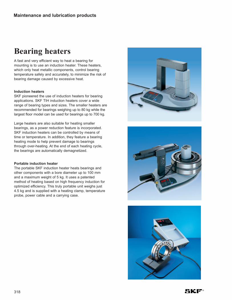
318
Bearing heatersA fast and very efficient way to heat a bearing formounting is to use an induction heater. These heaters,which only heat metallic components, control bearingtemperature safely and accurately, to minimize the risk ofbearing damage caused by excessive heat.
Induction heaters SKF pioneered the use of induction heaters for bearingapplications. SKF TIH induction heaters cover a widerange of bearing types and sizes. The smaller heaters arerecommended for bearings weighing up to 80 kg while thelargest floor model can be used for bearings up to 700 kg.
Large heaters are also suitable for heating smallerbearings, as a power reduction feature is incorporated.SKF induction heaters can be controlled by means oftime or temperature. In addition, they feature a bearingheating mode to help prevent damage to bearingsthrough over-heating. At the end of each heating cycle,the bearings are automatically demagnetized.
Portable induction heaterThe portable SKF induction heater heats bearings andother components with a bore diameter up to 100 mmand a maximum weight of 5 kg. It uses a patentedmethod of heating based on high frequency induction foroptimized efficiency. This truly portable unit weighs just4.5 kg and is supplied with a heating clamp, temperatureprobe, power cable and a carrying case.
Maintenance and lubrication products

319
Hot platesThe SKF electric hot plate heats small bearings and othermachinery components. It is suitable for bearings with anoutside diameter up to approximately 170 mm or with aweight up to 4 kg. A lid for retaining the heat alsoprevents dirt from entering the bearing.
Heating devices to remove inner ringsA range of special heating devices for removingcylindrical roller bearing inner rings from shafts isavailable from SKF. Aluminium heating rings are designedfor dismounting inner rings of small and medium-sizecylindrical roller bearings. Adjustable induction heatersare also available for frequent dismounting of varioussizes of cylindrical roller bearing inner rings. Two sizes areavailable covering raceway diameters from 80 to 170 mm.Non-adjustable induction heaters are designed to suit aparticular bearing and application. They are normally usedto dismount inner rings of multi-row cylindrical rollerbearings.
GlovesSKF heat resistant gloves specially designed for the handlingof heated bearings and other machine components.
Maintenance and lubrication products

320
Hydraulic toolsA variety of hydraulic tools is available to mount anddismount bearings in a safe and controlled manner. TheSKF oil injection method enables easy working while theSKF Drive-up Method provides accurate results.
Hydraulic nutsHMV .. E type hydraulic nuts enable mounting anddismounting of bearings with tapered bores of 50 mm andabove. When compared with mechanical methods, theyconsiderably reduce the time and effort needed to installor remove a bearing. SKF HMV .. E nuts are availablewith metric or imperial threads or with a plain bore.
SKF HMV .. E nuts, when used in conjunction with SKFpumps fitted with a digital pressure gauge and a dialindicator, allow the full advantages of the SKF Drive-upMethod to be realized.
Maintenance and lubrication products

Hydraulic pumps and oil injectorsSKF hand-operated hydraulic pumps can developpressures up to 150 MPa. They can be supplied with ahighly accurate pressure gauge, which allows the SKFDrive-up Method to be employed. All pumps arecontained in a sturdy carrying case complete with a hose,quick connection coupling, nipple and mounting fluid.
Oil Injectors can supply oil pressures up to 400 MPa. TheSKF range comprises single injectors as well as anumber of kits, which contain an injector and a selectionof the most common accessories such as an adapterblock, high-pressure pipes and nipples.
For large bearings and applications requiring a largervolume of oil, several air-driven portable pumps andinjectors providing pressures up to 300 MPa areavailable.
Hydraulic accessoriesTo facilitate connections between hydraulic tools andmost applications, SKF offers a wide range of accessoriesincluding pressure gauges, high pressure pipes,connection nipples and mounting and dismounting fluids.
Maintenance and lubrication products
321

322
InstrumentsTo realize maximum bearing life, it is important todetermine the operating condition of machinery and their bearings. With the SKF measuring instrument range,critical environmental conditions can be analysed toachieve optimum bearing performance.
TachometersOptical measurement is a safe and reliable technique todetermine rotational speed. Using non-contactinstruments is often essential to meet industrial safetyregulations. SKF provides a range of highly accurate optical tachometers. A range of accessories enableslinear and direct contact rotational speeds to bemeasured.
ThermometersThe temperature of a bearing or bearing housing is aquick and easy indication of the running conditions of the bearing. SKF provides a range of contact and non-contact thermometers from the indispensable ThermoPenup to a highly accurate, advanced dual channel, widerange thermometer. A comprehensive range oftemperature probes for a variety of applications is also available.
Electronic stethoscopeThe noise of a machine can help indicate troublesomeparts such as damaged bearings, valve chatter, tappetnoise, piston slap and gear and pump noise. The SKFelectronic stethoscope is a hand-held instrument thatpicks up the noise or vibration from a machine via aprobe and helps the user locate the source of the noise.
Maintenance and lubrication products

323
Oil check monitorThe SKF oil check monitor determines oil condition byanalysing the contamination levels and electro-chemicalchanges in both mineral and synthetic based oils. It wasdeveloped originally for engine oils but is suitable for gearand lubrication oils. It can also help to detect water, anti-freeze or metallic particles in an oil sample.
Alignment instruments and shimsSKF has developed laser alignment tools to make themachinery alignment process faster, easier and morereliable. Using the latest laser technology, the SKF shaftalignment tool measures both the parallel and angularalignment of shafts to be connected.
SKF's belt alignment tool aligns the grooves in a pulleyrather than the pulley face, facilitating accurate andsimultaneous adjustment of belt tension and pulleyalignment.
A comprehensive range of pre-cut machinery shims in bothmetric and inch dimensions is available as well as stainlesssteel double slot shims for use with many housings.
Maintenance and lubrication products

Maintenance and lubrication products
324
Lubricants and lubricatorsThe formulation of all SKF bearing greases is based onextensive research, grease performance testing and fieldexperience.
SKF developed many of the internationally acceptedbearing-related grease testing parameters. For correctlubricant application, a range of lubrication equipment isavailable from SKF.
GreasesSKF offers a range of high quality lubricating greases tosuit many bearing applications and conditions. Thegreases have been developed specifically to meet theneeds of rolling bearings and their application conditions.A guide to select the most suitable SKF grease can befound on pages 328-330.
Grease guns and pumpsThe SKF range also includes grease guns, manual andair-driven grease pumps and grease filler pumps. Greasefiller pumps are used to fill grease guns and greasepackers from standard SKF grease drums.
Grease meterThe SKF grease meter can accurately measure thevolume of grease pumped into a bearing. A wide range ofaccessories is available.

325
SYSTEM 24 single point automatic lubricatorSKF SYSTEM 24 is a single point automatic lubricator,pre-filled with SKF grease or oil. Compared with traditionalmanual relubrication techniques, SKF SYSTEM 24provides a more accurate control of the quantity oflubricant supplied. It can be set to continuously supply thecorrect amount of quality lubricant over a given timeperiod, up to a maximum of one year.
DialSet 3.0The new version of the SKF re-lubrication calculationprogram has been updated according to the latestlubrication theories published by SKF in the GeneralCatalogue (5000), released in 2003. This program isavailable on CD-ROM in six languages and suitable forPC’s working with MS Windows 95 or later. A web versionof the DialSet is currently being developed.
SYSTEM MultiPoint automatic lubricatorSKF SYSTEM MultiPoint is a microprocessor controlledautomatic lubricator. Grease can be supplied to up to eightpoints, using standard SKF grease cartridges. Thecartridges assure the user that only clean fresh grease isused. SYSTEM MultiPoint lubricator has been tested andapproved for use with all SKF bearing greases.
Oil levellerThe SKF oil levellers are designed for automaticadjustment of the optimal oil level in oil bath lubricatedapplications. They effectively solve the problem ofadjusting the correct oil level during operation or due toleakage rather than just during standstill.
Maintenance and lubrication products

326
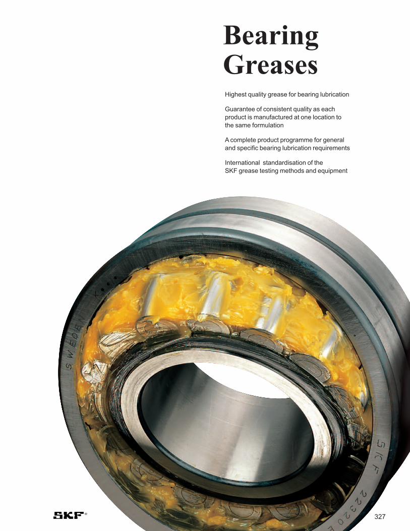
BearingGreasesHighest quality grease for bearing lubrication
Guarantee of consistent quality as each product is manufactured at one location to the same formulation
A complete product programme for general and specific bearing lubrication requirements
International standardisation of the SKF grease testing methods and equipment
327

SKF grease for all-important applications
328
‡ Agricultural equipment ‡ Automotive wheel bearings
‡ Conveyors ‡ Small electric motors
All purpose bearing grease for a wide range ofindustrial and automotive applications
LGMT 2
‡ Bearings >100 mm shaft size ‡ Outer ring rotation‡ Vertical shaft applications
‡ Continuous high ambienttemperatures >35 °C
‡ Propeller shafts
All purpose bearing grease for a wide range ofapplications like LGMT 2 where higher consistency is required
LGMT 3
‡ Pulp and paper making machines‡ Jaw crushers
‡ Traction motors for rail vehicles‡ Dam gates
EP bearing grease for a wide range of industrial andautomotive applications
LGEP 2
‡ Textile spinning spindles‡ Machine tool spindles‡ Instruments and
control equipment
‡ Small electric motors used inmedical and dental equipment
Low temperature bearing grease for high speedand low noise applications
LGLT 2
‡ Electric motors‡ Hot fans‡ Water pumps‡ Rolling bearings in textile, paper
processing and drying machines
‡ Applications with high speed ballbearings operating at mediumand high temperatures
‡ Replaces LGHQ 3
High performance, wide temperature, long life, high speed polyurea thickened bearing grease
LGHP 2
‡ Bakery equipment‡ Food processing equipment ‡ Multipack cassette bearings
‡ Wrapping machines‡ Conveyor bearings
Food processing bearing grease NSF H1LGFP 2
‡ Agricultural and forestryequipment
‡ Construction and earthmovingequipment
‡ Mining and conveying equipment‡ Water treatment and irrigation‡ Turf, lawn, golf equipment
‡ Locks, dams, bridges‡ Linkages, rod ends‡ Pleasure craft propellers
and shafts‡ Other applications where
contamination of the environment is a concern
Green biodegradable low toxicity bearing greaseLGGB 2
‡ Wheel bearings in cars and trucks
‡ Washing machines‡ Electric motors
Wide temperature, long-life bearing greaseLGWA 2
‡ Steel on steel plain bearings‡ Pulp and paper making machines‡ Asphalt vibrating screens‡ Continuous casting machines
‡ Sealed spherical roller bearingsoperating up to 150 °C/300 °F
‡ Withstands peak temperatures of 200 °C/392 °F
EP bearing grease for high temperature industrial applications
LGHB 2
‡ Bakery equipment (ovens)‡ Hot fans‡ Kiln truck wheels‡ Load rollers in copying machines
‡ Any applications operating underextremely high temperatureand/or in aggressiveenvironments
Extreme temperature, high performance, long life,fluorinated bearing grease
LGET 2
‡ Rolling element bearings runningat low speed and very high loads
‡ Jaw crushers‡ Track laying machines
‡ Lift mast wheels‡ Building machines such as
mechanical rams, crane arms,crane hooks
EP bearing grease with molybdenum disulphide forindustrial and heavy equipment
LGEM 2
‡ Windmills ‡ Screw conveyorsEP bearing grease for low temperature applicationsLGWM 1
‡ Trunnion bearings on rotating drums
‡ Support and thrust rollers on rotary kilns and dryers
‡ Bucket wheel excavators‡ Slewing ring bearings‡ High pressure roller mills
EP bearing grease with molybdenum disulphide forheavy industrial applications
LGEV 2
Standard bearing greases Special bearing greases

SKF Bearing Grease Selection
Main additional properties Grease recommended
LGMT 3
LGFP 2
LGGB 2
LGEP 2
LGWM 1
LGHB 2
LGEM 2
LGEV 2
LGHB 2
LGHP 2
LGLT 2
LGHB 2
LGWA 2
LGMT 2
Temp Speed Load
Temperature
Speed for ball bearings
Load
Speed for roller bearings
LGMT 2
LGHP 2
LGLT 2
LGEP 2
LGFP 2
LGGB 2
Unless:
Green biodegradable, demands for low toxicity
Food processing industry
Shock loads, heavy loads, vibrations
Low ambient -50 ̊ C/-58 ̊ F, expected bearing temperature < 50 ̊ C/122 ̊ F
Expected bearing temperature continuously > 100 ̊ C/212 ̊ F
Green biodegradable
Food processing
High load
Low temperature
High temperature
Note: - For areas with relatively high ambient temperatures, use LGMT 3 instead of LGMT 2- For special operating conditions, refer to the range of special SKF bearing greases
Generally use
M = Medium -30 to 110 ̊ C/-22 to 230 ̊ FH = High -20 to 130 ̊ C/-4 to 266 ̊ FL = Low -50 to 80 ̊ C/-58 to 176 ̊ F
EH = Extremely High n.dm over 700.000VH = Very High n.dm up to 700.000H = High n.dm up to 500.000M = Medium n.dm up to 300.000
VH = Very high C/P < 2H = High C/P = 2-5M = Medium C/P = 5-10L = Low C/P > 10
H = High n.dm over 150.000M = Medium n.dm up to 150.000L = Low n.dm up to 75.000VL = Very Low n.dm below 30.000
M M M
M M M
M M M
M M M+H
M L H
M L H
M L H
M VL VH
M VL VH
M VL VH
L EH L
M+H M+H M
H L+M H
H L+M M+H
General purpose for small/medium-sized bearings
General purpose for larger bearings (or high ambient temp.)
Food compatible
Biodegradable, low toxicity, EP/anti-wear
EP/anti-wear, good corrosion inhibition
EP/anti-wear, good low temperature performance, anti-brinelling
EP/anti-wear, severe vibrations, anti-brinelling, water resistance
Excellent EP/anti-wear (solid additives), high viscosity
Excellent EP/anti-wear (solid additives), extremely high viscosity
Extremely good EP, anti-brinelling, water resistance
Quiet running, very low start-up temperature
Excellent corrosion protection, water resistance, long grease life
Extremely good EP, anti-brinelling, water resistance
EP/anti-wear, leakage resistant, water resistance
Quick bearing grease selection guide
Basic bearing grease selection
n.dm= rotational speed, r/min x 0,5 (D+d), mm / Note: For bearing temperatures > 200 ºC / 392 ºF (up to 260 ºC / 500 ºF) refer to LGET 2
Bearing operating parameters
All-purpose
329

LGMT 2
(*1) mm2/s at 40 °C/104 °F = cSt. (*3) LGWA 2 can withstand peak temperatures of 220 °C/428 °F (*2) For continuous operation: max. temperatures 90 °C/194 °F (*4) LGHB 2 can withstand peak temperatures of 200 °C/392 °F
All purpose industrial and automotive
-30/120 °C-22/250 °F
Lithium soap/mineral oil
110 35, 200 g tube, 420 ml cartridge,1, 5, 18, 50, 180 kg
LGMT 3All purpose industrial and automotive
-30/120 °C-22/250 °F
Lithium soap/mineral oil
120-130 420 ml cartridge, 1, 5, 18, 50, 180 kg
LGEP 2Extreme pressure -20/110 °C
-4/230 °FLithium soap/mineral oil
200 420 ml cartridge, 1, 5, 18, 50, 180 kg
LGLT 2Low temperature -55/110 °C
-65/230 °FLithium soap/di-ester oil
15 200 g tube, 1, 180 kg
LGHP 2High performancepolyurea grease
-40/150 °C-40/300 °F
Di-urea/mineral oil
96 420 ml cartridge, 1, 5, 18, 50, 180 kgSYSTEM 24
LGFP 2Food compatible -20/110 °C
-4/230 °FAluminium complex/medical white oil
130 420 ml cartridge, 1, 18, 180 kgSYSTEM 24
Bearing working conditions
Description Temperature range
Thickener/ base oil
Base oil viscosity (*1)
Available pack sizes
Technical specifications
LGGB 2Green biodegradable low toxicity
-40/120 °C (*2)-40/250 °F
Lithium-calcium soap/synthetic ester oil
110 420 ml cartridge5, 18, 180 kgSYSTEM 24
LGWA 2Wide temperature (*3) -30/140 °C
-22/284 °FLithium complex soap/mineral oil
185 35, 200 g tube, 420 ml cartridge, 1, 5, 50, 180 kgSYSTEM 24
LGHB 2
LGET 2
EP high viscosity high temperature (*4)
-20/150 °C-4/300 °F
Complex calciumsulphonate/mineral oil
400-450 420 ml cartridge, 5, 18, 50, 180 kgSYSTEM 24
LGEM 2
Extreme temperature -40/260 °C-40/500 °F
PTFE/Synthetic(fluorinated polyether)
400 50 g (25 ml) syringe
LGEV 2
High viscosity plus solid lubricants
-20/120 °C-4/250 °F
Lithium soap/mineral oil
500 420 ml cartridge, 5, 18, 180 kgSYSTEM 24
LGWM 1
Extremely high viscositywith solid lubricants
-10/120 °C14/250 °F
Lithium-calcium soap/mineral oil
1.020 35 g tube,420 ml cartridge5, 18, 50, 180 kg
Extreme pressure low temperature
-30/110 °C-22/230 °F
Lithium soap/mineral oil
200 420 ml cartridge, 5, 50, 180 kg
Standard bearing greases
Special bearing greases
SKF Bearing Grease Technical Specifications
330

347
112 Self-Aligning Ball Bearing. . . . . . . . . . . . . . . . . . . . . . . . . 10213 Self-Aligning Ball Bearing. . . . . . . . . . . . . . . . . . . . . . . . . 102112 Self-Aligning Ball Bearing. . . . . . . . . . . . . . . . . . . . . . . . . 106130 Self-Aligning Ball Bearing. . . . . . . . . . . . . . . . . . . . . . . . . 104139 Self-aligning ball bearing . . . . . . . . . . . . . . . . . . . . . . . . . 104160(00) Z & 2Z Single row deep groove ball bearing with shields . . . . . . 45161(00) Z & 2Z Single row deep groove ball bearing with shields . . . . . . 441726200 and 1726300 Deep groove ball bearing with sphered o/d . . . . 245
2200 Single row deep groove ball bearing with filling slots . . . . 582200 Self-aligning ball bearing . . . . . . . . . . . . . . . . . . . . . . . . . 1022300 Self-aligning ball bearing . . . . . . . . . . . . . . . . . . . . . . . . . 102213(00) Spherical roller bearing . . . . . . . . . . . . . . . . . . . . . . . . . . 166200 NR Single row deep groove ball bearing
with filling slots & snap ring . . . . . . . . . . . . . . . . . . . . . . . . 59200 R & RD MRC single row angular contact ball
bearing with 15 degree contact angle (SKF 7200CD type) . . . . . MRC Engineering catalogue
200 S MRC single row deep groove ball bearings (SKF 6200 type) . . . . . MRC Engineering catalogue
200 S--C MRC single row Cartridge design . . . . . . . . . . . . . . . . . . . 72200-Z & 2Z Single row deep groove ball bearing
with filling slots and shields . . . . . . . . . . . . . . . . . . . . . . . . 58200-ZNR and 2ZNR Single row deep groove ball bearing
with filling slots, shields and snap ring . . . . . . . . . . . . . . . . 592200-2RS1 Self-aligning ball bearing, sealed . . . . . . . . . . . . . . . . . . . 105222(00) (P.Press pg. 177) Spherical roller bearing . . . . . . . . . . . . . . . . . 166223(00) (P.Press pg. 177) Spherical roller bearing . . . . . . . . . . . . . . . . . 166223(00) VA405 Spherical roller bearing Vibratory type . . . . . . . . . . . . . . 176230(00) Spherical roller bearing . . . . . . . . . . . . . . . . . . . . . . . . . . 167230(00)-2CS2 Spherical roller bearing with seals . . . . . . . . . . . . . . . . . . 1742300-2RS1 Self-aligning ball bearing, sealed . . . . . . . . . . . . . . . . . . . 105231(00) (P. Press pg. 177) Spherical roller bearing . . . . . . . . . . . . . . . . 167231(00)-2CS2 Spherical roller bearing with seals . . . . . . . . . . . . . . . . . . 174232(00) (P. Press pg. 177) Spherical roller bearing . . . . . . . . . . . . . . . . 167232(00)-2CS2 Spherical roller bearing with seals . . . . . . . . . . . . . . . . . . 175238(00) Spherical roller bearing . . . . . . . . . . . . . . . . . . . . . . . . . . 169239(00) Spherical roller bearing . . . . . . . . . . . . . . . . . . . . . . . . . . 168239(00)-2CS Spherical roller bearing with seals . . . . . . . . . . . . . . . . . . 175240(00) Spherical roller bearing . . . . . . . . . . . . . . . . . . . . . . . . . . 166240(00)-2CS Spherical roller bearing with seals . . . . . . . . . . . . . . . . . . 174241(00) Spherical roller bearing . . . . . . . . . . . . . . . . . . . . . . . . . . 167241(00)-2CS Spherical roller bearing with seals . . . . . . . . . . . . . . . . . . 174248(00) Spherical roller bearing . . . . . . . . . . . . . . . . . . . . . . . . . . 171249(00) Spherical roller bearing . . . . . . . . . . . . . . . . . . . . . . . . . . 172292(00) Spherical roller thrust bearing . . . . . . . . . . . . . . . . . . . . . 208293(00) Spherical roller thrust bearing . . . . . . . . . . . . . . . . . . . . . 208294(00) Spherical roller thrust bearing . . . . . . . . . . . . . . . . . . . . . 208
3300 Single row deep groove ball bearing with filling slots . . . . 58300 R & RD MRC single row angular contact ball
bearings with 15 degree contact angle . . . . . . . . . . . . . . . 83300 S MRC single row deep groove ball bearings
. . . . . . . . . . . . . . . . . . . . . . . . . MRC Engineering catalogue300-SFFC Cartridge design . . . . . . . . . . . . . . . . . . . . . . . . . . . . . . . . . 72300-2Z Single row deep groove ball bearing
with filling slots and shields . . . . . . . . . . . . . . . . . . . . . . . . 58300-2ZNR Single row deep groove ball bearing with
filling slots, shields and snap ring. . . . . . . . . . . . . . . . . . . . 59300-NR Single row deep groove ball bearing
with filling slots and snap ring . . . . . . . . . . . . . . . . . . . . . . 59300-Z Single row deep groove ball bearing
with filling slots and shield . . . . . . . . . . . . . . . . . . . . . . . . . 58300-ZNR Single row deep groove ball bearing with
filling slots, shield and snap ring . . . . . . . . . . . . . . . . . . . . 59302(00) (sets pg. 153) Single row metric taper roller bearing. . . . . . . . . 146303(00) (sets pg. 153) Single row metric taper roller bearing. . . . . . . . . 1463057(00) Double row cam follower . . . . . . . . . . . . . . . . . . . . . . . . . . 973058(00) Double row cam follower . . . . . . . . . . . . . . . . . . . . . . . . . . 97
3194(00) DA-2LSV Full complement double row cylindrical roller bearing . . . . . . . . . . . . . . . . . . . . . . . . . . 138
320(00) X (sets pg. 153)Single row taper roller bearing . . . . . . . . . . . . . 1463200 A Double row angular contact ball bearing . . . . . . . . . . . . . . 913200 A-2RS1 Double row angular contact ball bearing with seals. . . . . . 933200 A-2Z Double row angular contact ball bearing with shields . . . . 93322(00) (sets pg. 153) Single row taper roller bearing . . . . . . . . . . . . . . 146323(00) (sets pg. 153) Single row taper roller bearing . . . . . . . . . . . . . . 146329(00) Single row taper roller bearing . . . . . . . . . . . . . . . . . . . . . 15033(00) A Double row angular contact ball bearing . . . . . . . . . . . . . . 9133(00) A-2RS1 Double row angular contact ball bearing with seals . . . . . 9333(00) A-2Z Double row angular contact ball bearing with shields . . . . 9333(00) D Double row angular contact ball
bearing with split inner ring . . . . . . . . . . . . . . . . . . . . . . . . 9133(00) DNR Double row angular contact ball bearing
with snap ring groove and snap ring (split inner) . . . . . . . . 91330(00) (sets pg. 153) Single row taper roller bearing . . . . . . . . . . . . . . 148331(00) (sets pg. 153) Single row taper roller bearing . . . . . . . . . . . . . . 147332(00) (sets pg. 153) Single row taper roller bearing . . . . . . . . . . . . . . 1463612(00) R Single row cam roller . . . . . . . . . . . . . . . . . . . . . . . . . . . . . 67
4400 R & RD MRC single row angular contact ball
bearing with 15 degree contact angle . . . . . . . . . . . . . . . . 8542(00) A Double row deep groove ball bearing . . . . . . . . . . . . . . . . 6643(00) A Double row deep groove ball bearing . . . . . . . . . . . . . . . . 6645(0000), 46(0000) Printing Press bearings . . . . . . . . . . . . . . . . . . . . . . 1804523(00) Spherical roller Vibratory type bearings . . . . . . . . . . . . . . 1784762(00) Spherical roller, collar mount
bearings for unit blocks . . . . . . . . . . . . . . . . . . . . . . . . . . 262
5511(00) Single direction thrust ball bearing . . . . . . . . . . . . . . . . . . 196512(00) Single direction thrust ball bearing . . . . . . . . . . . . . . . . . . 196513(00) Single direction thrust ball bearing . . . . . . . . . . . . . . . . . . 196514(00) Single direction thrust ball bearing . . . . . . . . . . . . . . . . . . 19652(00) A Double row angular contact ball
bearing Conrad type . . . . . . . . . . . . . . . . . . . . . . As 32(00) A52(00) E & 53(00) E Double row angular contact
ball bearing filling slot type . . . . . . . . . . . . . . . . . . . . . . . . . 94522(00), 523(00), 524(00) Double direction thrust ball bearing . . . . . . . . 202532(00), 533(00), 534(00) Single direction thrust ball bearing. . . . . . . . . 2005400 A Double row angular contact ball bearing . . . . . . . . . . . . . . 9254420 Double direction thrust ball bearing . . . . . . . . . . . . . . . . . 204
6600 Single row deep groove ball bearing . . . . . . . . . . . . . . . . . 34600 seals/shields Single row deep groove ball
bearings with shields or seals . . . . . . . . . . . . . . . . . . . . . . 436000 Single row deep groove ball bearing . . . . . . . . . . . . . . . . . 346000 N & NR Single row deep groove ball bearing
with snap ring groove . . . . . . . . . . . . . . . . . . . . . . . . . . . . . 556000 RSH &2RSH Single row deep groove ball bearing
with contact seal(s), new version . . . . . . . . . . . . . . . . . . . . 446000 RSL & 2RSL Single row deep groove ball bearing
with light contact seal(s), new version . . . . . . . . . . . . . . . . 446000/HC5 Single row hybrid deep groove ball bearings . . . . . . . . . . . .
. . . . . . . . . . . . . . . . . . . . . . . . . . . Hybrid bearings catalogue6000/VA201 Single row deep groove ball bearing
for high temperatures . . . . . . . . . . . . . . . . Hi-temp catalogue6000-2RS1/HC5 Single row hybrid deep groove ball
bearing with contact seal(s) . . . . Hybrid bearings catalogue6000-2RSL/HC5 Single row hybrid deep groove ball
bearing with light contact seal(s) . Hybrid bearings catalogue6000-2RZ Single row deep groove ball bearing
with non contact-seal . . . . . . . . . . . . . . . . . . . . . . . . . . . . . 446000-2RZ/HC5 Single row hybrid deep groove ball bearing
with non contact seals . . . . . . . . . Hybrid bearings catalogue6000-2Z/VA201 Single row deep groove ball bearing
for high temperatures . . . . . . . . . . . . . . . . Hi-temp catalogue
Part number index

348
6000-2Z/VA208 Single row deep groove ball bearing with shields for high temperatures . . . . . . . . . . Hi-temp catalogue
6000-RS1 & 2RS1 Single row deep groove ball bearing with contact seal(s) . . . . . . . . . . . . . . . . . . . . . . . . 44
6000-Z & 2Z Single row deep groove ball bearing with shield(s) . . . . . . 446000-ZNR &2ZNR Single row deep groove ball bearing
with shield(s) and snap ring . . . . . . . . . . . . . . . . . . . . . . . . 57618-- Single row deep groove ball bearing . . . . . . . . . . . . . . . . . 34618(00)-2RS1, 2RZ, 2Z Single row deep groove ball
bearing with contact seal . . . . . . . . . . . . . . . . . . . . . . . . . . 44619-- Single row deep groove ball bearing . . . . . . . . . . . . . . . . . 34619(00)-2RS1, 2RZ, 2Z Single row deep groove ball
bearing with contact seals . . . . . . . . . . . . . . . . . . . . . . . . . 446200 Single row deep groove ball bearing . . . . . . . . . . . . . . . . . 346200- 2Z-VA208 Single row deep groove ball bearing with
shields for high temperatures . . . . . . . . . . Hi-temp catalogue6200 N & NR Single row deep groove ball bearing
with snap ring groove . . . . . . . . . . . . . . . . . . . . . . . . . . . . . 556200/HC5 Single row hybrid deep
groove ball bearing. . . . . . . . . . . . Hybrid bearings catalogue6200/VA201 & 2Z/VA201 Single row deep groove ball
bearing for high temperatures. . . . . . . . . . Hi-temp catalogue6200/VL024 Single row deep groove ball
bearing with Insocoat® . . . . . . . . . . . . . . Insocoat® catalogue6200-2RS1/HC5 Single row hybrid deep groove
ball bearing with contact seal(s) . Hybrid bearings catalogue6200-2RSL/HC5 Single row hybrid deep groove
ball bearing with light contact seal(s), new version . . . . . . . . . . . Hybrid bearings catalogue
6200-2RZ Single row deep groove ball bearing with non contact-seal . . . . . . . . . . . . . . . . . . . . . . . . . . . . . 44
6200-2RZ/HC5 Single row hybrid deep groove ball bearing with non contact-seal. . . . Hybrid bearings catalogue
6200-2Z/VA228 Single row deep groove ball bearings with shields for high temperatures . . . . . . Hi-temp catalogue
6200-RSH & 2RSH Single row deep groove ball bearing with contact seals . . . . . . . . . . . . . . . . . . . . . . . . . 44
6200-RSL & 2RSL Single row deep groove ball bearing with light contact seal(s), new version . . . . . . . . . . . . . . . . 44
6200-Z & 2Z Single row deep groove ball bearing with shield(s) . . . . . . 446200-ZNR Single row deep groove ball bearing
with shield and snap ring . . . . . . . . . . . . . . . . . . . . . . . . . . 57622(00)-2RS1 Single row deep groove ball bearing with contact seals . . 44623(00)-2RS1 Single row deep groove ball bearing with contact seals . . 44628-2Z Single row deep groove ball bearing with shields . . . . . . . 44630/8-2RS1 Single row deep groove ball bearing with contact seals . . 446300 Single row deep groove ball bearing . . . . . . . . . . . . . . . . . 346300 N & NR Single row deep groove ball bearing
with snap ring groove . . . . . . . . . . . . . . . . . . . . . . . . . . . . . 556300/HC5 Single row hybrid ball bearing . . . Hybrid bearings catalogue6300/VL0241 Single row ball deep groove ball bearing with
Insocoat® on the outer ring . . . . . . . . . . Insocoat® catalogue6300/VL2071 Single row deep groove ball bearing with
Insocoat® on the bore . . . . . . . . . . . . . . Insocoat® catalogue6300-2A/VA201 Single row deep groove ball bearing
with shields for high temperatures . . . . . . Hi-temp catalogue6300-2Z/VA208 Single row deep groove ball bearing
with shields for high temperatures . . . . . . Hi-temp catalogue6300-2Z/VA228 Single row deep groove ball bearing
with shields for high temperatures . . . . . . Hi-temp catalogue6300-RS1 & 2RS1 Single row deep groove ball
bearing with contact seal(s) . . . . . . . . . . . . . . . . . . . . . . . . 446300-RSH & 2RSH Single row deep groove ball bearing
with contact seal(s) new version . . . . . . . . . . . . . . . . . . . . 446300-RSL & 2RSL Single row deep groove ball bearing
with light contact seal(s) new version. . . . . . . . . . . . . . . . . 446300-Z & 2Z Single row deep groove ball bearing with shield(s) . . . . . . 446300-ZNR & 2ZNR Single row deep groove ball
bearing with shield(s) and snap ring . . . . . . . . . . . . . . . . . 576400 Single row deep groove ball bearing . . . . . . . . . . . . . . . . . 35
7, 8, 97200, 7300, 7400 & D MRC single row angular contact
ball bearing with 29 degree contact angle . . . . . . . . . . . . . 867200 B Single row angular contact ball bearing
40 degree contact angle. . . . . . . . . . . . . . . . . . . . . . . . . . . 787300 B Single row angular contact ball bearing
40 degree contact angle. . . . . . . . . . . . . . . . . . . . . . . . . . . 78811(00) Cylindrical roller thrust bearing. . . . . . . . . . . . . . . . . . . . . 205812(00) Cylindrical roller thrust bearing. . . . . . . . . . . . . . . . . . . . . 205982(00) Single row deep groove ball bearings . . . . . . . . . . . . . . . 35
A, BAH Withdrawal sleeves. . . . . . . . . . . . . . . . . . . . . . . . . . . . . . 306AHX Withdrawal sleeves. . . . . . . . . . . . . . . . . . . . . . . . . . . . . . 306AOH Withdrawal sleeves for oil injection mounting . . . . . . . . . 309AOHX Withdrawal sleeves for oil injection mounting . . . . . . . . . 310BA Single direction thrust ball bearing . . . . . . . . . . . . . . . . . . 196BS2-22-2CS Sealed spherical roller bearing. . . . . . . . . . . . . . . . . . . . . 174BSC-V Full complement CARB® toroidal roller bearing . . . . . . . . 187
CC 22(00) CARB® toroidal roller bearing. . . . . . . . . . . . . . . . . . . . . . 186C 23(00) CARB® toroidal roller bearing. . . . . . . . . . . . . . . . . . . . . . 187C 30(00) CARB® toroidal roller bearing. . . . . . . . . . . . . . . . . . . . . . 188C 31(00) CARB® toroidal roller bearing. . . . . . . . . . . . . . . . . . . . . . 187C 39(00) CARB® toroidal roller bearing. . . . . . . . . . . . . . . . . . . . . . 189C 40(00) CARB® toroidal roller bearing. . . . . . . . . . . . . . . . . . . . . . 186C 40(00)-2CS5V Sealed full complement CARB® toroidal roller bearing 192C 41(00) CARB® toroidal roller bearing. . . . . . . . . . . . . . . . . . . . . . 187C 41(00)-2CS5V Sealed full complement CARB® toroidal roller bearing 192C 49(00) V CARB® toroidal roller bearing full complement . . . . . . . . 186C 59(00) V CARB® toroidal roller bearing full complement . . . . . . . . 186C 59(00)-2CS5V Sealed full complement CARB® toroidal roller bearing 192C 60(00) V CARB® toroidal roller bearing full complement . . . . . . . . 186C 69(00) V CARB® toroidal roller bearing full complement . . . . . . . . 186C 69-2CS5V Sealed full complement CARB® toroidal roller bearing . . 192C2F-SS MRC two bolt flanged unit with stainless steel bearing . . 266C2F-ZM MRC two bolt flanged unit with ZMaRC-coated bearing . 265C4F-SS MRC 4 bolt flanged unit with stainless steel bearing . . . . 268C4F-ZM MRC 4 bolt flanged unit with ZMaRC-coated bearing . . . 267CBF-SS MRC three bolt bracket flange unit
with stainless bearing . . . . . . . . . . . . . . . . . . . . . . . . . . . . 272CBF-ZM MRC three bolt bracket flange unit
with ZMaRC-coated bearing . . . . . . . . . . . . . . . . . . . . . . 271CPB-SS MRC unit block with stainless steel bearing. . . . . . . . . . . 264CPB-ZM MRC unit block with ZMaRC-coated bearing . . . . . . . . . 263CRL & CRM Single row Cylindrical roller bearings inch sizes . . . . . . . 140CTB-SS MRC tapped base unit block with
stainless steel bearing . . . . . . . . . . . . . . . . . . . . . . . . . . . 270CTB-ZM MRC tapped base unit block with
ZMaRC-coated bearing . . . . . . . . . . . . . . . . . . . . . . . . . . 269CTN-SS MRC narrow slot Take-up unit with
stainless steel bearing . . . . . . . . . . . . . . . . . . . . . . . . . . . 274CTN-ZM MRC narrow slot Take-up unit with
ZMaRC-coated bearing . . . . . . . . . . . . . . . . . . . . . . . . . . 273CTW-SS MRC wide slot Take-up unit with stainless steel bearing . 276CTW-ZM MRC wide slot Take-up unit with ZMaRC-coated bearing 275
FFSYE Roller bearing unit . . . . . . . . . . . . . . . . . . . . . . . . . . . . . . 254FSYE-N Roller bearing unit, ConCentra. . . . . . . . . . . . . . . . . . . . . 255FYE Four bolt roller bearing unit block. . . . . . . . . . . . . . . . . . . 256FY-FM Four bolt ball bearing flanged unit . . . . . . . . . . . . . . . . . . 225FYM-TF/AH Four bolt ball bearing flanged unit,
air handling, medium duty . . . . . . . . . . . . . . . . . . . . . . . . 237FYR Four bolt roller bearing flanged unit . . . . . . . . . . . . . . . . . 257FYRP Four bolt piloted roller bearing flanged unit . . . . . . . . . . . 258FY-TF Four bolt ball bearing flanged unit . . . . . . . . . . . . . . . . . . 223FY-TF/AH Four bolt ball bearing, air handling unit . . . . . . . . . . . . . . 236FYT-FM Two bolt ball bearing flanged unit. . . . . . . . . . . . . . . . . . . 228
Part number index

349
FYTM-TF Two bolt ball bearing flanged unit, medium duty . . . . . . . 229FYT-TF Two bolt ball bearing flanged unit. . . . . . . . . . . . . . . . . . . 226FYT-TF/AH Two bolt ball bearing flanged unit, air handling . . . . . . . . 235FYT-WF Two bolt ball bearing unit block . . . . . . . . . . . . . . . . . . . . 227FY-WF Four bolt ball bearing unit block . . . . . . . . . . . . . . . . . . . . 224
H, IH Adapter sleeve, series 2, 3, 23, 30, 31, and 39 . . . . . . . . 288HA, HE, HS Adapter sleeve for inch shafts, series
2, 3, 23, 30 and 31 . . . . . . . . . . . . . . . . . . . . . . . . . . . . . . 294I designation bearings Spherical roller bearing . . . . . . . . . . . . . . . . . . . 181ICOS-D1B Deep groove ball bearing with radial shaft seal . . . . . . . . . 54
NN 200 Single row cylindrical roller bearing . . . . . . . . . . . . . . . . . 112N 300 Single row cylindrical roller bearing . . . . . . . . . . . . . . . . . 112NCF 18 V Full complement single row cylindrical roller bearings. . . 129NCF 22 V Full complement single row cylindrical roller bearings. . . 129NCF 28 V Full complement single row cylindrical roller bearings. . . 131NCF 29 V Full complement single row cylindrical roller bearings. . . 128NCF 30 V Full complement single row cylindrical roller bearings. . . 128NJ 10 Single row cylindrical roller bearing . . . . . . . . . . . . . . . . . 118NJ 200 Single row cylindrical roller bearing . . . . . . . . . . . . . . . . . 112NJ 2200 Single row cylindrical roller bearing . . . . . . . . . . . . . . . . . 112NJ 2300 Single row cylindrical roller bearing . . . . . . . . . . . . . . . . . 112NJ 300 Single row cylindrical roller bearing . . . . . . . . . . . . . . . . . 112NJ 400 Single row cylindrical roller bearing . . . . . . . . . . . . . . . . . 113NJG 23 VH Full complement single row cylindrical roller bearings. . . 128NNC CV Full complement double row cylindrical
roller bearings, series 48 and 49 . . . . . . . . . . . . . . . . . . . 133NNCF CV Full complement double row cylindrical
roller bearings, series 48, 49 and 50 . . . . . . . . . . . . . . . . 133NNCL CV Full complement double row cylindrical
roller bearings, series 48 and 49 . . . . . . . . . . . . . . . . . . . 133NNF 50(00) ADA-2LSV Full complement double
row cylindrical roller bearing. . . . . . . . . . . . . . . . . . . . . . . 138NU 10 Single row cylindrical roller bearing . . . . . . . . . . . . . . . . . 112NU 12 Single row cylindrical roller bearing . . . . . . . . . . . . . . . . . 126NU 2/VL0241 Single row cylindrical roller bearing
with Insocoat® on the outer ring. . . . . . . Insocoat® catalogueNU 20 Single row cylindrical roller bearing . . . . . . . . . . . . . . . . . 126NU 200 Single row cylindrical roller bearing . . . . . . . . . . . . . . . . . 112NU 22 Single row cylindrical roller bearing . . . . . . . . . . . . . . . . . 112NU 23 Single row cylindrical roller bearing . . . . . . . . . . . . . . . . . 112NU 300 Single row cylindrical roller bearing . . . . . . . . . . . . . . . . . 112NU 300/VL0241 Single row cylindrical roller bearing
with Insocoat® on the outer ring. . . . . . . Insocoat® catalogueNU 400 Single row cylindrical roller bearing . . . . . . . . . . . . . . . . . 113NUP 200 Single row cylindrical roller bearing . . . . . . . . . . . . . . . . . 112NUP 2200 Single row cylindrical roller bearing . . . . . . . . . . . . . . . . . 112NUP 2300 Single row cylindrical roller bearing . . . . . . . . . . . . . . . . . 112NUP 300 Single row cylindrical roller bearing . . . . . . . . . . . . . . . . . 112
O, Q, ROH Adapter sleeve for oil injection . . . . . . . . . . . . . . . . . . . . . 291QJ 200 & QJ 300 Four point contact ball bearings . . . . . . . . . . . . . . . . . . 95R-- MRC inch series . . . . . . . . . . . . . . . . . . . . . . . . . . . . . . . . . 68RLS-- Single row deep groove ball bearings . . . . . . . . . . . . . . . . 69RMS-- Single row deep groove ball bearings . . . . . . . . . . . . . . . . 71RRH and RRZ-BBR MRC ZMaRC-coated insert bearings . . . . . . . . . . . 246
SS2F-SS MRC 2 bolt flanged unit with stainless
steel housing and bearing . . . . . . . . . . . . . . . . . . . . . . . . 284S4F-SS MRC 4 bolt flanged unit with stainless
steel housing and bearing . . . . . . . . . . . . . . . . . . . . . . . . 285SNW Inch size adapters sleeves (possible
substitutes for the HA, HE, HS series). . . . . . . . . . . . . . . 302
SPB-SS MRC stainless steel pillow block unit . . . . . . . . . . . . . . . . 283
SR-FM Pressed steel pillow block . . . . . . . . . . . . . . . . . . . . . . . . 231STB-SS MRC tapped base pillow block with
stainless steel housing and bearing . . . . . . . . . . . . . . . . . 286SY PF & AH Ball bearing unit block, ConCentra and air handling . . . . 238SYE Roller bearing unit block . . . . . . . . . . . . . . . . . . . . . . . . . 250SYE-N Roller bearing pillow block ConCentra . . . . . . . . . . . . . . . 251SY-FM Ball bearing unit block . . . . . . . . . . . . . . . . . . . . . . . . . . . 217SYH-FM Ball bearing unit block, low base to centre. . . . . . . . . . . . 222SYH-RM Ball bearing unit block, low base to centre. . . . . . . . . . . . 220SYH-TF Ball bearing unit block, low base to centre. . . . . . . . . . . . 219SYH-TF/AH Ball bearing unit block, low base to centre. . . . . . . . . . . . 233SYH-WF Ball bearing unit block, low base to centre. . . . . . . . . . . . 221SYM-TF Ball bearing unit block, medium duty . . . . . . . . . . . . . . . . 218SYM-TF/AH Ball bearing unit block, air handling . . . . . . . . . . . . . . . . . 234SYR Roller bearing unit block . . . . . . . . . . . . . . . . . . . . . . . . 252SYR-N Roller bearing unit block ConCentra . . . . . . . . . . . . . . . . 253SYT Roller bearing unit block - metric ConCentra . . . . . . . . . . 261SY-TF Ball bearing unit block . . . . . . . . . . . . . . . . . . . . . . . . . . . 216SY-TF/AH Ball bearing unit block, air handling . . . . . . . . . . . . . . . . . 232
TT2DD Single row taper roller bearing, ISO series . . . . . . . . . . . 149T2ED Single row taper roller bearing, ISO series . . . . . . . . . . . 147T2EE Single row taper roller bearing, ISO series . . . . . . . . . . . 147T3FE Single row taper roller bearing, ISO series . . . . . . . . . . . 150T4CB Single row taper roller bearing, ISO series . . . . . . . . . . . 152T4DB Single row taper roller bearing, ISO series . . . . . . . . . . . 153T4EB Single row taper roller bearing, ISO series . . . . . . . . . . . 154T5ED Single row taper roller bearing, ISO series . . . . . . . . . . . 151T7FC (sets pg. 153) Single row taper roller bearing, ISO series . . . . . . 147TBR Roller bearing take-up unit . . . . . . . . . . . . . . . . . . . . . . . . 259TBR-N Roller bearing take-up unit ConCentra. . . . . . . . . . . . . . . 260TFN-SS MRC narrow slot stainless steel Take-up frames. . . . . . . 277TFW-SS MRC wide slot stainless steel Take-up frames. . . . . . . . . 278TU--TF Ball bearing take-up units. . . . . . . . . . . . . . . . . . . . . . . . . 230
WW60 Stainless deep groove ball bearing . . . . . . . . . . . . . . . . . . 60W60-2RS1 Stainless deep groove ball bearing with seals . . . . . . . . . . 60W60-2Z Stainless deep groove ball bearing with shields . . . . . . . . 60W617(00) Stainless deep groove ball bearing . . . . . . . . . . . . . . . . . . 60W618 Stainless deep groove ball bearing . . . . . . . . . . . . . . . . . . 60W618-2Z Stainless deep groove ball bearing with shields . . . . . . . . 60W619 Stainless deep groove ball bearing . . . . . . . . . . . . . . . . . . 60W619(00)-2RS1 Stainless deep groove ball bearing with seals . . . . . . . . 64W619(00)-2Z Stainless deep groove ball bearing with shields . . . . . . . . 64W6200 Stainless deep groove ball bearing . . . . . . . . . . . . . . . . . . 60W6200-2RS1 Stainless deep groove ball bearing with seals . . . . . . . . . . 63W6200-2Z Stainless deep groove ball bearing with shields . . . . . . . . 63W627-2Z Stainless deep groove ball bearing with shields . . . . . . . . 62W628-2Z Stainless deep groove ball bearing with shields . . . . . . . . 63W6300 Stainless deep groove ball bearing . . . . . . . . . . . . . . . . . . 60W6300-2Z Stainless deep groove ball bearing with shields . . . . . . . . 63W637-2Z Stainless deep groove ball bearing with shields . . . . . . . . 62W638-2Z Stainless deep groove ball bearing with shields . . . . . . . . 63W639-2Z Stainless deep groove ball bearing with shields . . . . . . . . 63
Y, ZYAR-2F Y-bearing with grub screw locking . . . . . . . . . . . . . . . . . . 242YAT Y-bearing with grub screw locking . . . . . . . . . . . . . . . . . . 244YEL-2F Y-bearing with eccentric locking collar . . . . . . . . . . . . . . . 241YET Y-bearing with eccentric locking collar . . . . . . . . . . . . . . . 240Z2F-ZM MRC 2 bolt flanged unit with ZMaRC-coated
cast iron block and bearing. . . . . . . . . . . . . . . . . . . . . . . . 280Z4F-ZM MRC 4 bolt flanged unit with ZMaRC-coated
cast iron block and bearing . . . . . . . . . . . . . . . . . . . . . . . 281ZPB-ZM MRC cast iron pillow block unit with
ZMaRC-coated bearing . . . . . . . . . . . . . . . . . . . . . . . . . . 279ZTB-ZM MRC tapped base pillow block with ZMaRC
coated cast iron block and bearing . . . . . . . . . . . . . . . . . 282
Part number index

350