Embed Size (px)
Citation preview

Sketch out 5 isometric cuboids on the back of your booklet
REMEMBER 30 degree diagonal lines Vertical lines Parallel NO HORIZONTAL LINES

Learning Objectives: ALL will understand the term Exploded Level 4
MOST will be able to draw in Exploded Level 5
SOME will accurately apply presentation skills to your drawings Level 6
Homework : Find out what a vector graphic is

Then work away
from the line,
drawing lines up
at 30 degrees.
Connect the top two
edges by working at 30
degrees again. They
should meet exactly.
This drawing shows the shape
in more detail than the oblique
projection.
Put the two
side lines in,
making sure
they are
vertical.
Begin by drawing the
centre edge of your
shape. Draw it
vertically up the page.

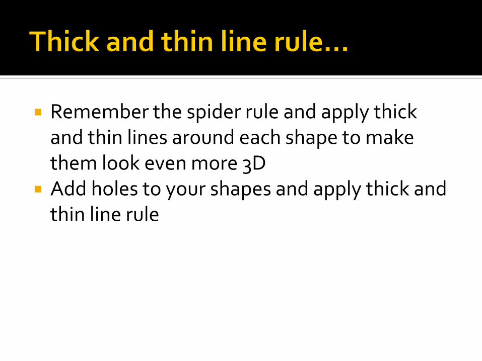
Remember the spider rule and apply thick and thin lines around each shape to make them look even more 3D
Add holes to your shapes and apply thick and thin line rule


Decide where the light source would be and shade the blocks in 3 tones:
• Light tone• Mid tone • Dark tone
Add background colour as per the example


EXPLODED ISOMETERIC PROJECTION
Designers use ‘exploded’ views, often drawn in isometric projection, to show parts of productsthat are hidden from sight. For example, look at the following examples to see how this works
With exploded isometric projection, all the parts are in line with each other, along a centre line.This is drawn precisely through the centre of the product being drawn.
With a normal isometric drawing, all the parts are in their assembled positions. This means thatvital hidden detail cannot be seen.


Designers also use exploded views to explain their designs to clients/customersand manufacturers. Furthermore, exploded views of products are often suppliedto customers, who in turn assemble the product. A good example of this is 'knockdown' furniture. When the flat pack is opened, an instruction sheet or bookletexplains how the furniture is assembled, often in the form of isometric explodedviews.
The drawings seen below, were supplied with an instruction booklet. They aretwo of numerous diagrams drawn in isometric projection. They help explain howthe cabinet and all its component parts are assembled, to form the finished
product.
These are accurate drawings constructed by a designer, that explain how theproduct he/she has designed is assembled.


What is exploded isometric drawing? Where might I see these drawings Why are they useful? How can I use these skills?