Embed Size (px)
Citation preview

Name Designation Affiliation Signature
Authored by:
T.J. Cornwell, SKA Architect
Date: Owned by:
A.M. MacPherson, Head of Project
Date: Approved by:
P.J. Diamond, Director General
Date: Released by:
P.J. Diamond, Director General
SKA1 TELESCOPE CALIBRATION FRAMEWORK
Document number ........................................................................ SKA-‐TEL-‐SKO-‐0000000 Context ........................................................................................................ AG-‐CAL-‐FRM Revision ........................................................................................................................ DE Author .......................................................................................................... T.J. Cornwell Date ............................................................................................................... 2015-‐04-‐08 Document Classification .......................................................................... UNRESTRICTED Status ....................................................................................................................... Draft

Document No.: Revision: Date:
SKA-‐TEL-‐SKO-‐0000000 D 2015-‐04-‐08
UNRESTRICTED Author: T.J. Cornwell
Page 2 of 28
Date:
DOCUMENT HISTORY
Revision Date Of Issue Engineering Change Number
Comments
A 2014-‐11-‐10 -‐ First draft release for internal review
DOCUMENT SOFTWARE
Package Version Filename
Wordprocessor MsWord Word 2007 SKA-‐TEL-‐SKO-‐0000000-‐Telescope_CalibrationD.docx
Block diagrams
Other
ORGANISATION DETAILS Name SKA Organisation
Registered Address Jodrell Bank Observatory
Lower Withington
Macclesfield
Cheshire
SK11 9DL
United Kingdom
Registered in England & Wales Company Number: 07881918
Fax. +44 (0)161 306 9600 Website www.skatelescope.org

Document No.: Revision: Date:
SKA-‐TEL-‐SKO-‐0000000 D 2015-‐04-‐08
UNRESTRICTED Author: T.J. Cornwell
Page 3 of 28
CONTENTS
1 Introduction ................................................................................................................ 7 1.1 Purpose of the document ................................................................................................. 7 1.2 Scope of the document ..................................................................................................... 7
2 References ................................................................................................................... 8 2.1 Applicable documents ...................................................................................................... 8 2.2 Reference documents ....................................................................................................... 8
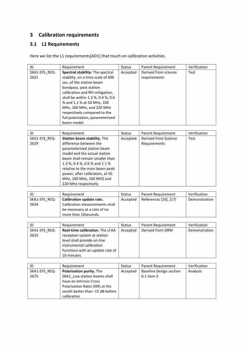
3 Calibration requirements ............................................................................................. 9 3.1 L1 Requirements .............................................................................................................. 9 3.2 Analysis ........................................................................................................................... 13
4 Calibration framework ............................................................................................... 14
5 Centralisation of Calibration Framework .................................................................... 19
6 Telescope Calibration Framework .............................................................................. 20 6.1 Design and development ................................................................................................. 20 6.2 Commissioning and operations ........................................................................................ 20
7 Calibration of SKA1 Telescopes .................................................................................. 21 7.1 Calibration of SKA1_Low ................................................................................................. 22 7.2 Calibration of SKA1_Mid .................................................................................................. 24
8 Modifications to Statements of Work ........................................................................ 26
9 Additional L1 requirements ....................................................................................... 27 9.1 Missing L1 requirements ................................................................................................. 27
10 The Way Forward .................................................................................................... 28

LIST OF FIGURES
Figure 1 Project documentation structure. ............................................................................ 14 Figure 2 Operations documents ............................................................................................. 14 Figure 3 Conceptual map of calibration framework ............................................................... 17 Figure 4 Conceptual map of imaging framework ................................................................... 17 Figure 6 SKA1 Context diagram .............................................................................................. 21 Figure 7 Low Product Tree ...................................................................................................... 22 Figure 8 Mid Product Tree ...................................................................................................... 24 Figure 9 Plan for a Calibration Consultation for SKA1-‐Low, showing the input topics and the
output models. .............................................................................................................. 28

LIST OF TABLES Table 6-‐1 Element responsibility for calibration ..................................................................... 20

Document No.: Revision: Date:
SKA-‐TEL-‐SKO-‐0000000 D 2015-‐04-‐08
UNRESTRICTED Author: T.J. Cornwell
Page 6 of 28
LIST OF ABBREVIATIONS
Acronym Definition AA Aperture Array ACM Auto Correlation Matrix AG Architecture Group CSP Central Signal Processing DSH Dish Consortium ECP Engineering Change Proposal ICD Interface Control Document INFRA Infrastructure Consortium LFAA Low Frequency Aperture Array LINFRA Local Infrastructure LMC Local Monitor and Control LOW Low frequency component of SKA1 MID Mid frequency component of SKA1 MRO Murchison Radio Observatory OPS Operations RBS Rebaselining RFI Radio Frequency Interference SADT Signals and Data Transport SAT Synchronisation And Timing SCI Science SDP Science Data Processing SKA Square Kilometre Array SKADC SKA Design Consortium SKAO Square Kilometre Array Organisation (or Office) SKO SKA Office TBA To Be Advised TBC To Be Confirmed TBD To Be Decided TM Telescope Manager WBS Work Breakdown Structure

1 Introduction
1.1 Purpose of the document
The purpose of this document is to describe the SKA1 system level framework for calibration of SKA1 telescopes. The word “framework” is taken to mean a set of coherently defined processes and procedures that may be adapted for one of a small set of related purposes – specifically calibration of SKA1-‐Low and SKA1-‐Mid. One assumption is therefore that calibration of these telescopes has much in common – conceptually and practically. This is a system framework because it specifies responsibilities for all Elements. Calibration necessarily includes information flow from all Project Elements, but the two Elements most directly involved are TM and SDP. Indeed calibration would be ideally designed by an Element that combined TM and SDP functions. Unfortunately since TM and SDP are separate Elements in SKA, much of the architecture and design of calibration has to be done at the system level. We urge readers to bear that fact in mind.
1.2 Scope of the document
This document presents a unified view of the system calibration of all aspects of an SKA1 telescope, and aspects of calibration of the individual telescopes, Low and Mid. The context is post 2015 RBS. System calibration includes all aspects of the measurement process, not just those directly related to astronomical observations. “System” denotes that the operation of the entire telescope is considered, even though only one component may be the subject of the calibration process. Calibration of a single component, such as antenna pointing model, is considered to be a special case of system calibration. This document will be of direct relevance to all elements, to SCI and OPS. The scope includes the design and use of the framework but not the implementation in any of the elements. Therefore this is not a software design document. By the very, system-‐focused, level of this document, we provide only a sketch of the calibration of the two SKA Telescopes, SKA1-‐Mid and SKA1-‐Low. Specifically we do not examine the details of the calibration required. Detailed accounts are given elsewhere.

2 References
2.1 Applicable documents
The following documents are applicable to the extent stated herein. In the event of conflict between the contents of the applicable documents and this document, the applicable documents shall take precedence.
[AD1] Cornwell, T., Turner, W., et al, 2014, “SKA PHASE 1 SYSTEM (LEVEL 1) REQUIREMENTS SPECIFICATION” SKA-‐OFF.SE.ARC-‐SKO-‐SRS-‐001_3
[AD2] Cornwell, T., “SKA Telescope Calibration Template”, SKA-‐TEL-‐SKO-‐0000000-‐Telescope_Calibration TemplateA
2.2 Reference documents
The following documents are referenced in this document. In the event of conflict between the contents of the referenced documents and this document, this document shall take precedence. There are currently no Reference Documents.
3 Calibration requirements
3.1 L1 Requirements
Here we list the L1 requirements[AD1] that touch on calibration activities.
ID Requirement Status Parent Requirement Verification SKA1-‐SYS_REQ-‐2621
Spectral stability: The spectral stability, on a time scale of 600 sec.,of the station beam bandpass, post station calibration and RFI-‐mitigation, shall be within 1.3 %, 0.4 %, 0.6 % and 1.1 % at 50 MHz, 100 MHz, 160 MHz, and 220 MHz respectively compared to the full polarization, parameterized beam model.
Accepted Derived from science requirements
Test
ID Requirement Status Parent Requirement Verification SKA1-‐SYS_REQ-‐2629
Station beam stability. The difference between the parameterized station beam model and the actual station beam shall remain smaller than 1.3 %, 0.4 %, 0.6 % and 1.1 % relative to the main beam peak power, after calibration, at 50 MHz, 100 MHz, 160 MHZ and 220 MHz respectively
Accepted Derived from Science Requirements
Test
ID Requirement Status Parent Requirement Verification SKA1-‐SYS_REQ-‐2634
Calibration update rate. Calibration measurements shall be necessary at a rate of no more than 10seconds.
Accepted References [16], [17] Demonstration
ID Requirement Status Parent Requirement Verification SKA1-‐SYS_REQ-‐2635
Real-‐time calibration. The LFAA reception system at station level shall provide on-‐line instrumental calibration functions with an update rate of 10 minutes
Accepted Derived from DRM Demonstration
ID Requirement Status Parent Requirement Verification SKA1-‐SYS_REQ-‐2675
Polarisation purity. The SKA1_Low station beams shall have an Intrinsic Cross Polarization Ratio (IXR) at the zenith better than -‐15 dB before calibration
Accepted Baseline Design section 6.1 item 3
Analysis

Document No.: Revision: Date:
SKA-‐TEL-‐SKO-‐0000000 D 2015-‐04-‐08
UNRESTRICTED Author: T.J. Cornwell
Page 10 of 28
The polarisation purity of reflector antenna shall be expressed by using the intrinsic polarisation ratio (IXR). It will give coordinate system independent FoM of the polarisation purity and quantify the polarimetric performances even after the calibration.
ID Requirement Status Parent Requirement Verification SKA1-‐SYS_REQ-‐2630
Station Beam stability. Station beams shall have a maximal RMS stability within TBD % RMS of a TBD mask over the calibration period of 10s TBC with a zenith pointing direction across the full frequency band with one failed signal path
Accepted TBJ Test
ID Requirement Status Parent Requirement Verification SKA1-‐SYS_REQ-‐2805
SKA1_Mid fine frequency channel amplitude variation. The fine frequency channels for the SKA1_Mid channeliser shall have a total amplitude variation as a function of frequency of less than 0.01 dB after bandpass calibration
Accepted Signal processing chain performance document in preparation
Test
The VLBI community indicate there should be at least 4 beams generated for VLBI usage: one for target and three for calibrators to establish calibration plane.
ID Requirement Status Parent Requirement Verification SKA1-‐SYS_REQ-‐2633
Beam polarization stability. The polarisation properties of the beams shall be stable enough to allow their calibration to be better than TBD %
Accepted TBJ Test
ID Requirement Status Parent Requirement Verification SKA1-‐SYS_REQ-‐2280
System status. The system shall extract information about the current condition of the system from the science and calibration data streams, and log this information along with other relevant system and environmental status information. Based on this information, it shall be possible to monitor, save, and analyse the technical performance of the system.
Accepted ConOps 5.2 Demonstration
The Forensic tool for telescope behaviour will draw upon the monitor data archive, the System Configuration database, Alarm Log, Calibration data, and other related sources of information.
Document No.: Revision: Date:
SKA-‐TEL-‐SKO-‐0000000 D 2015-‐04-‐08
UNRESTRICTED Author: T.J. Cornwell
Page 11 of 28
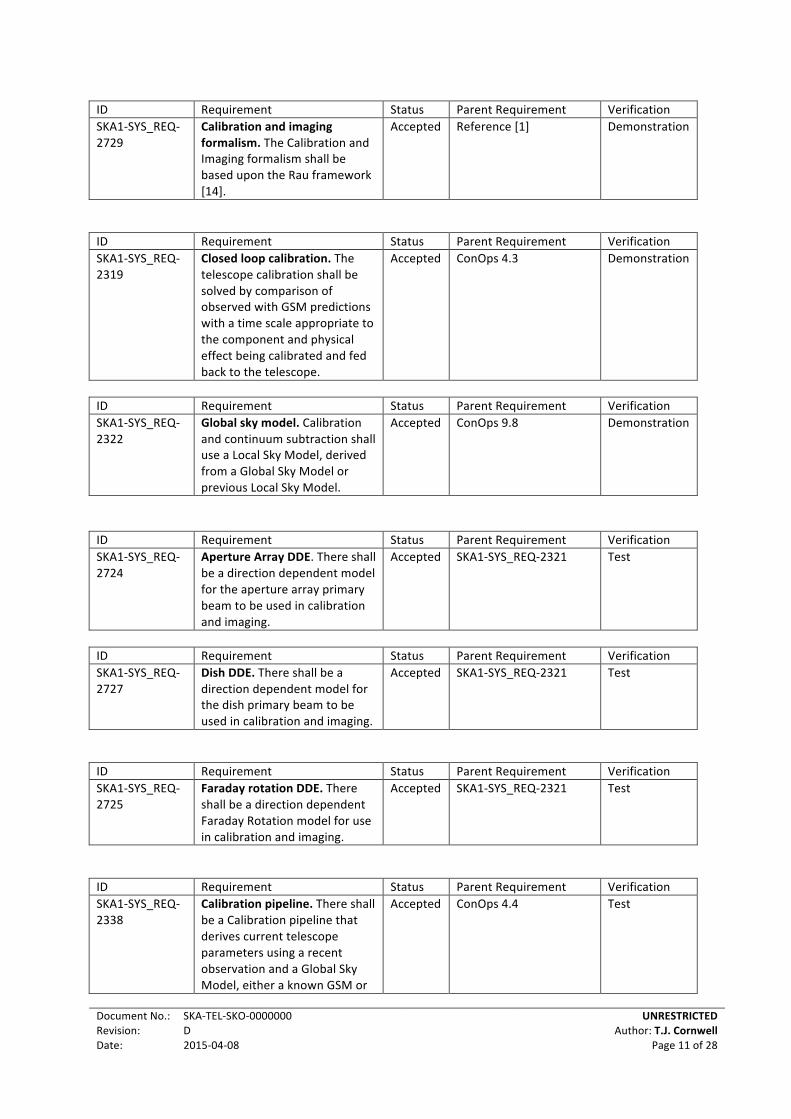
ID Requirement Status Parent Requirement Verification SKA1-‐SYS_REQ-‐2729
Calibration and imaging formalism. The Calibration and Imaging formalism shall be based upon the Rau framework [14].
Accepted Reference [1] Demonstration
ID Requirement Status Parent Requirement Verification SKA1-‐SYS_REQ-‐2319
Closed loop calibration. The telescope calibration shall be solved by comparison of observed with GSM predictions with a time scale appropriate to the component and physical effect being calibrated and fed back to the telescope.
Accepted ConOps 4.3 Demonstration
ID Requirement Status Parent Requirement Verification SKA1-‐SYS_REQ-‐2322
Global sky model. Calibration and continuum subtraction shall use a Local Sky Model, derived from a Global Sky Model or previous Local Sky Model.
Accepted ConOps 9.8 Demonstration
ID Requirement Status Parent Requirement Verification SKA1-‐SYS_REQ-‐2724
Aperture Array DDE. There shall be a direction dependent model for the aperture array primary beam to be used in calibration and imaging.
Accepted SKA1-‐SYS_REQ-‐2321 Test
ID Requirement Status Parent Requirement Verification SKA1-‐SYS_REQ-‐2727
Dish DDE. There shall be a direction dependent model for the dish primary beam to be used in calibration and imaging.
Accepted SKA1-‐SYS_REQ-‐2321 Test
ID Requirement Status Parent Requirement Verification SKA1-‐SYS_REQ-‐2725
Faraday rotation DDE. There shall be a direction dependent Faraday Rotation model for use in calibration and imaging.
Accepted SKA1-‐SYS_REQ-‐2321 Test
ID Requirement Status Parent Requirement Verification SKA1-‐SYS_REQ-‐2338
Calibration pipeline. There shall be a Calibration pipeline that derives current telescope parameters using a recent observation and a Global Sky Model, either a known GSM or
Accepted ConOps 4.4 Test

Document No.: Revision: Date:
SKA-‐TEL-‐SKO-‐0000000 D 2015-‐04-‐08
UNRESTRICTED Author: T.J. Cornwell
Page 12 of 28
the most recent GSM. ID Requirement Status Parent Requirement Verification SKA1-‐SYS_REQ-‐2339
Continuum imaging pipeline. There shall be a Continuum Imaging pipeline that shall have the goal of constructing noise-‐limited wide-‐band images for observations up to 1000h integration time. Polarisation shall be available if requested or necessary for calibration or quality assurance.
Accepted SKA1-‐SYS_REQ-‐2128 Test
ID Requirement Status Parent Requirement Verification SKA1-‐SYS_REQ-‐2692
Coherence loss 1min. The SKA frequency reference system shall provide a 2% maximum coherence loss, equivalent to 0.2 radians, within a maximum solution interval for in-‐beam calibration of 1 minute.
Accepted Baseline Design Addendum SKA-‐TEL-‐SKO-‐DD-‐003
Demonstration
ID Requirement Status Parent Requirement Verification SKA1-‐SYS_REQ-‐2693
Frequency reference phase drift. The SKA Frequency Reference System shall have a phase drift of less than 1 radian, over calibration intervals of up to 10 minutes, when using out of beam calibration sources.
Accepted Baseline design addendum SKA-‐TEL.SKO-‐DD-‐003
Demonstration
ID Requirement Status Parent Requirement Verification SKA1-‐SYS_REQ-‐2695
Pulse per second phase relative to UTC. The SKA synchronisation and timing system shall provide a 1PPS heartbeat signal with phase relative to UTC that over a 10 minute calibration interval shall survive synchronisation loss.
Accepted Baseline design addendum SKA-‐TEL-‐SKO-‐DD-‐003
Demonstration
ID Requirement Status Parent Requirement Verification SKA1-‐SYS_REQ-‐2337
Ingest pipeline. There shall be an Ingest pipeline that ingests data from the Correlator and Telescope Manager, applies known correction, flags known RFI, applies known calibration, and averages in time and frequency as required.
Accepted TBJ Test
ID Requirement Status Parent Requirement Verification SKA1-‐SYS_REQ-‐2694
Frequency reference rms. The SKA Frequency Reference
Accepted Baseline design addendum SKA-‐TEL.SKO-‐
Demonstration

Document No.: Revision: Date:
SKA-‐TEL-‐SKO-‐0000000 D 2015-‐04-‐08
UNRESTRICTED Author: T.J. Cornwell
Page 13 of 28
System shall have phase variability about a linear slope calibration, of less than 0.05 radians RMS, for calibration intervals of up to 10 minutes, using out of beam calibration sources.
DD-‐003
ID Requirement Status Parent Requirement Verification SKA1-‐SYS_REQ-‐2542
Training A plan detailing the training required for maintenance, calibration and repair shall be generated.
Accepted SKA1-‐SYS_REQ-‐2802 Inspection
3.2 Analysis
The overall calibration capabilities as constrained by the L1 Requirements can be summarised as:
• Telescope calibration is closed-‐loop, no faster than 10 seconds; there are currently no requirements on how quick calibration needs to be applied.
• Station calibration is closed-‐loop, no faster than 10 minutes. • A Global Sky Model is used for Telescope calibration • Application of calibration corrections occurs at the beamformers and at ingest to SDP for
imaging. • There are relatively few performance requirements • Direction-‐dependent effects must be handled • Telescope self-‐calibration may be needed in the SDP pipelines
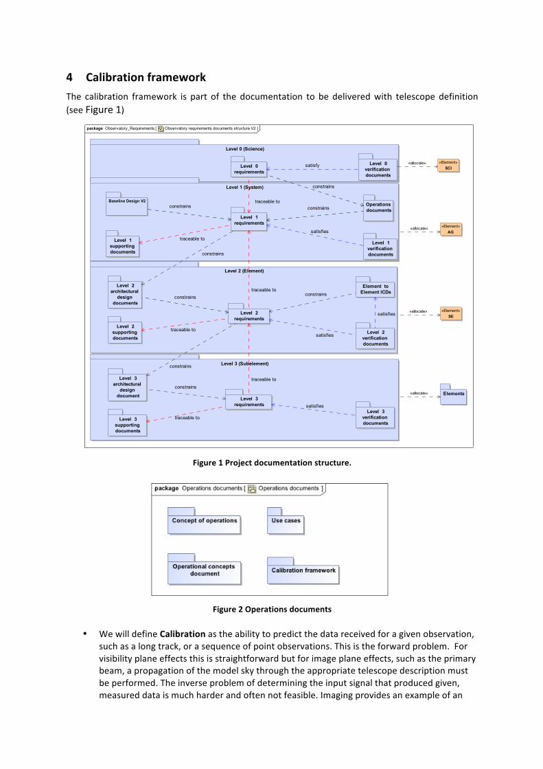
4 Calibration framework The calibration framework is part of the documentation to be delivered with telescope definition (see Figure 1)
Figure 1 Project documentation structure.
Figure 2 Operations documents
• We will define Calibration as the ability to predict the data received for a given observation,
such as a long track, or a sequence of point observations. This is the forward problem. For visibility plane effects this is straightforward but for image plane effects, such as the primary beam, a propagation of the model sky through the appropriate telescope description must be performed. The inverse problem of determining the input signal that produced given, measured data is much harder and often not feasible. Imaging provides an example of an
Observatory requirements documents structure V2Observatory_Requirementspackage [ ]
Level 0 (Science)
Level 0 verification documents
Level 0 requirements
Level 1 (System)
Baseline Design V2
Level 1 requirements
Level 1 verification documents
Level 1 supporting documents
Operations documents
Level 3 (Subelement)
Level 3 requirements
Level 3 architectural
design document
Level 3 supporting documents
Level 3 verification documents
traceable to
constrains
Level 2 (Element)
Level 2 requirements
Level 2 verification documents
Element to Element ICDs
Level 2 architectural
design documents
Level 2 supporting documents
Elements
«Element»SCI
«Element»AG
«Element»SE
constrains
satisfy «allocate»
traceable toconstrains
satisfies
constrains
traceable to
constrains
satisfies
traceable to
constrains
constrains
traceable to
constrains
satisfies
traceable to
satisfies «allocate»
«allocate»
«allocate»
Document No.: Revision: Date:
SKA-‐TEL-‐SKO-‐0000000 D 2015-‐04-‐08
UNRESTRICTED Author: T.J. Cornwell
Page 15 of 28
inverse problem. We will therefore not consider imaging or other inverse aspects in this memo.
• The input signal is always an electromagnetic field, which might be referred to a standard
location outside the Earth’s ionosphere. We measure the EM field after propagation through the atmosphere, at the focus of an antenna. The output data can be spatial and temporal correlations of these inputs or time-‐series.
• There is a signal path composed of Products. In the analogue part of the signal path, gains,
delays, non-‐linear effects, addition, etc. affect the signal. In the digital part, the signal should not be affected, except by some error. To be concrete, we will take the signal path to terminate at the Ingest phase of the Imaging Processor, or the equivalent for the Time Series Processor.
• Post-‐ingest, the effects of the known calibration terms are corrected. We will call this step
Calibration Correction. Note that Calibration Correction is not as well defined as Calibration because it may involve an inverse problem.
• Successful calibration allows a null experiment – the differences between the observed data
and the predicted data are consistent with the known noise processes.
• The calibration state is captured in a finite set of Calibration parameters. These calibration parameters may be determined by observing a known calibration source and then using a procedure to determine the calibration parameters via fitting or similar process. These parameters are then used on the target source. Usually a model of the target source will be constructed in some way and compared and adjusted iteratively until the observed and predicted data are consistent.
The difficulty with calibration comes from the number, complexity, and interrelatedness of physical processes that must be calibrated. The SKA1 product tree shows all the active elements in the telescopes down to product level 4. Below level 4 there are more active elements requiring calibration. In addition, the environment must also be calibrated in the above definition of calibration – we must be able to predict the effects of a given component of the environment of the observed data. Some elements of the product tree can be calibrated once or infrequently, perhaps using a non-‐astronomical approach, and then the calibration parameters used thereafter. The pointing model of a dish provides an excellent example. The form and parameters of the pointing model can be determined at DSH qualification and thereafter determined during AIV and changed only occasionally during special pointing calibration observations. There are three cases to be considered:
• If the calibration parameters can be determined by stand-‐alone, non-‐astronomical or non-‐interferometric measurements, then the calibration of that product can be performed in isolation.
• The more common circumstance is that a telescope has many products or environmental factors that must be calibrated purely from measured data and assumptions about the input source. Usually there will be degeneracies in the effect of products on the measured data. These must be broken by a carefully designed measurement strategy in which the

Document No.: Revision: Date:
SKA-‐TEL-‐SKO-‐0000000 D 2015-‐04-‐08
UNRESTRICTED Author: T.J. Cornwell
Page 16 of 28
configuration of the telescope is changed sequentially. The complete set of measured data can then be used to determine the calibration parameters of the products or environmental factors. In the simplest case, this corresponds to alternating between a known, point source calibrator, and the target source. In a more complex observation, one might want to untangle the various gain terms – the phase delay of the atmosphere, the complex gain of the receiver for each hand of polarisation, the leakage between polarisations, and the band passes. These effects vary on different timescales and so estimation of the calibration parameters must take that into account. It is possible to do a global solution for all the parameters, but often it is easier to solve incrementally and sequentially.
• The calibration source may be in the field being observed, which case joins smoothly into self-‐calibration.
• Finally there are circumstances in which a standalone calibration is possible but is limited in accuracy and must be further improved by calibration on astronomical sources of known properties.
For a concrete example, consider the location of an antenna, which is involved in the Point function. Theodolite (too time-‐consuming), laser ranging (possible), or GPS (better) may be used to determine the location. These measurements provide a certain accuracy and context (or reference frame). Measurement of a set of radio sources using the entire telescope will provide holistic, consistent information on the antenna locations with a certain accuracy and reference frame (this time referred to that used for the radio sources). To determine the antenna locations from the measurements requires a model of the measurement process that is parameterised by the antenna pointing. In the case of antenna pointing, the calibration strategy may be, for example, such the antennas are directed to move in a cross pattern around a radio source while the strength of the sources is monitored. For a global solution, this is repeated for sources all across the sky (in azimuth and elevation). For a local model, this would be repeated only for sources nearby. From a least-‐squares fit, the pointing parameters can be determined. The specific way in which the observations are made and the parameters solved is just as important as the equations describing the model. We call this a Calibration strategy. It is conceptualised as a sequence of observations and data reductions. The calibration strategy cannot be standalone but must be connected to the architecture of the telescope, most specifically the top-‐level descriptions of behaviour (via functional analysis) and structure (product tree[AD1]and other diagrams). Only functions of the telescope can be used to calibrate the telescope as a system, and to then use the telescope for observations. Hence the functional analysis is key. The functions edged by a black box impinge upon the system calibration, either by producing data that is used in the calibration process or by having parameters that must be determined. The functions in the functional analysis are allocated to products in the product tree (Figure 5). We call this model of the telescope a Telescope Model. The Telescope Model is itself a collection of models, one or more for each product. The Telescope Model contains Telescope Parameters. This overall conceptual model is shown in Figure 3. Although we do not discuss imaging in this memo, for clarity we show the complementary imaging strategy in Figure 4.

Document No.: Revision: Date:
SKA-‐TEL-‐SKO-‐0000000 D 2015-‐04-‐08
UNRESTRICTED Author: T.J. Cornwell
Page 17 of 28
Figure 3 Conceptual map of calibration framework
Figure 4 Conceptual map of imaging framework

Document No.: Revision: Date:
SKA-‐TEL-‐SKO-‐0000000 D 2015-‐04-‐08
UNRESTRICTED Author: T.J. Cornwell
Page 18 of 28
Figure 5 Product tree for SKA1
Obs
erva
tory
_Pro
duct
Tree
_Lev
el4
Obs
erva
tory
[Pac
kage
] bd
d [
]
«Pro
duct
»
Aus
tral
ian
Obs
erva
tory
«Pro
duct
»
Sou
th A
fric
an O
bser
vato
ry
«Pro
duct
»
Mid
«Pro
duct
»
Mur
chis
on R
adio
Obs
erva
tory
Sha
red
Faci
litie
s«P
rodu
ct»
Kar
oo R
adio
Ast
rono
my
Res
erve
Sha
red
Faci
litie
s
«Pro
duct
»
Low
«Pro
duct
»
Sur
vey
Dia
gram
nam
eO
bser
vato
ry_P
rodu
ctTr
ee_L
evel
4
Aut
hor
Tim
Cor
nwel
l
Cre
atio
n da
te9/
24/1
4 11
:28
AM
Mod
ifica
tion
date
9/24
/14
11:5
2 A
M
«Pro
duct
»
Sur
vey
Tele
scop
e M
anag
er
«Pro
duct
»
Aus
tral
ian
Eng
inee
ring
O
pera
tions
Cen
tre
«Pro
duct
»
Sou
th A
fric
an
Eng
inee
ring
O
pera
tions
Cen
tre
«Pro
duct
»
Low
Tel
esco
pe
Man
ager
«Pro
duct
»
Low
Con
figur
atio
n«P
rodu
ct»
Low
Out
er S
tatio
n«P
rodu
ct»
Mid
Pul
sar
Tim
ing
Eng
ine
«Pro
duct
»
Mid
Pul
sar
Sea
rch
Pro
cess
or
«Pro
duct
»
Low
Inne
r S
tatio
n
«Pro
duct
»
MR
O s
ite m
onito
r
Mid
cen
tral
fr
eque
ncy
refe
renc
e
«Pro
duct
»S
urve
y Im
agin
g P
roce
ssor
«Pro
duct
»
Sou
th A
fric
an
Sci
ence
O
pera
tions
C
entr
e
«Pro
duct
»
Sou
th A
fric
an
Sci
ence
Arc
hive
«Pro
duct
»
«Pro
duct
»S
urve
y S
ynch
roni
satio
n an
d tim
ing
Sou
th A
fric
an
Sci
ence
P
roce
ssin
g C
entr
e
«Pro
duct
»
«Pro
duct
»
Mid
Arr
ay
Bea
mfo
rmer
«Pro
duct
»
Aus
tral
ian
Sci
ence
P
roce
ssin
g C
entr
e
«Pro
duct
»
MR
O W
ater
an
d sa
nita
tion
«Pro
duct
»
Aus
tral
ian
Sci
ence
O
pera
tions
C
entr
e
«Pro
duct
»
Aus
tral
ian
Sci
ence
A
rchi
ve
«Pro
duct
»
Sur
vey
Net
wor
k
«Pro
duct
»
MR
O B
uild
ings
«Pro
duct
»
Mee
rKA
TPro
xy
«Pro
duct
»
Low
Cor
rela
tor
«Pro
duct
»Lo
w
Syn
chro
nisa
tion
and
tim
ing
«Pro
duct
»
Sur
vey
Ant
enna
S
tatio
n
«Pro
duct
»
Mid
Pul
sar
Tim
ing
Pro
cess
or
«Pro
duct
»
Mid
Pul
sar
Sea
rch
Eng
ine
«Pro
duct
»
Sur
vey
Cor
rela
tor
«Pro
duct
»
Mid
fo
unda
tions
«Pro
duct
»
KR
AR
site
m
onito
r
«Pro
duct
»M
id
Syn
chro
nisa
tion
and
tim
ing
«Pro
duct
»
KR
AR
RFI
m
onito
r
«Pro
duct
»
Sur
vey
Con
figur
atio
n
«Pro
duct
»K
RA
R R
efug
esK
RA
R
Bui
ldin
gs
«Pro
duct
»
KR
AR
Air
stri
p«P
rodu
ct»
«Pro
duct
»
Mid
Ant
enna
S
tatio
n
«Pro
duct
»M
RO
Ref
uges
«Pro
duct
»
Mid
C
onfig
urat
ion
«Pro
duct
»
Low
Sta
tion
Con
figur
atio
n
«Pro
duct
»
AS
KA
PP
roxy
«Pro
duct
»
MR
O A
irst
rip
«Pro
duct
»
Low
Net
wor
k
«Pro
duct
»
KR
AR
Roa
ds
«ext
erna
l»A
SK
AP
«Pro
duct
»
KR
AR
Pow
er
«ext
erna
l»M
eerK
AT
«Pro
duct
»
KR
AR
W
ater
and
sa
nita
tion
«Pro
duct
»S
urve
y V
LBI
«Pro
duct
»
Mid
Net
wor
k
«Pro
duct
»
MR
O P
ower
«Pro
duct
»
MR
O R
oads
«Pro
duct
»
Low
Im
agin
g P
roce
ssor
«Pro
duct
»
Mid
Te
lesc
ope
Man
ager
«Pro
duct
»
Mid
C
orre
lato
r
«Pro
duct
»
MR
O R
FI
mon
itor
«Pro
duct
»Lo
w V
LBI
«Pro
duct
»M
id V
LBI

5 Centralisation of Calibration Framework Calibration must be performed for many products in the Telescopes. The overall approach for development of the calibration framework capabilities is:
1. The Elements, particularly DSH and LFAA, are formally responsible (via the existing SOW) for providing models to the SKAO for their products. The term “model” here means functions and data allowing the prediction of the state of a product.
2. TM will incorporate these product models as part of the Telescope Model. In some cases, it might be appropriate for SDP to implement these within a high-‐performance computing environment.
3. TM is responsible for choreographing observations and attaching meta-‐data appropriately to the measurements.
4. SDP is responsible for converting observational data and meta-‐data into science data products. This includes visibility calibration solution and correction.
Calibration approaches may evolve over time in response to the existing performance requirements. We can expect that station-‐based calibration may be augmented or replaced by telescope-‐based calibration using the entire telescope to determine calibration of each station in a holistic approach. This would probably one come after years of operation and optimisation. In addition, on-‐going maintenance will be necessary after operations start. Since the Elements that responsible for the products will disappear at the end of construction, maintenance and further development are assumed to be the responsibility of an Operations computing team. These points argue for centralisation of as much of the calibration strategy as possible into the single TM code framework and away from the multiple and possibly divergent LMC code frameworks. Thus, solution of Telescope Model parameters will be centralised in either TM or SDP, and away from the product LMCs. This centralisation has the following advantages:
• Algorithm resource requirements can grow without having to upgrade all relevant Telescope LMCs. For example, concurrent processing could be utilised as needed.
• Maintenance and development of the Telescope Model will not require knowledge of the numerous individual LMC code frameworks.
• Simulation can use the modelling capabilities directly in the knowledge that there is no version or code mismatch.
For example, ACM information from the aperture arrays will be sent to TM for solution of antenna gains, and weights and calibration information returned as needed. The disadvantages to centralisation are:
• Derivation of a common framework • Possible performance overheads
This centralisation is a key element of the SKA1 Architecture. Waivers may be requested and will be reviewed by the SKA Architect.

6 Telescope Calibration Framework
6.1 Design and development
The Elements will be responsible as follows:
Table 6-‐1 Element responsibility for calibration Element Principal responsibility
AIV • Verification of system calibration CSP • Apply calibration and weights in correlator and central
beamformers DSH • Provide primary beam models, pointing models, calibration
procedures, etc. for Telescope Model • Provide calibration measurements to TM • Apply calibration and weights in PAF beamformers
INFRA • Provide input information for calibration e.g. antenna locations LFAA • Provide antenna primary beam models, station models,
calibration procedures, etc. for Telescope Model • Provide calibration measurements to TM • Apply calibration and weights in AA beamformers
SADT • Application of timing corrections SCI • Provide models and calibration procedures for external factors
such as troposphere, ionosphere, Galactic plane, etc. SDP • Execution of calibration strategy and consequent processes
• Calibration solvers, calibration application, and calibration correction
TM • Instantiation of calibration strategy and processes of scheduling blocks
• Telescope Model
The SKAO Architecture Group is responsible for:
• Definition of SKA1 approach to system calibration (this and related documents) • Definition of contents of Telescope Model, Telescope Parameters • Initial definition of operational aspects of Calibration Strategy
6.2 Commissioning and operations
During commissioning and operations, the SKA Operations Group is assumed to be responsible for execution of all aspects of this calibration strategy
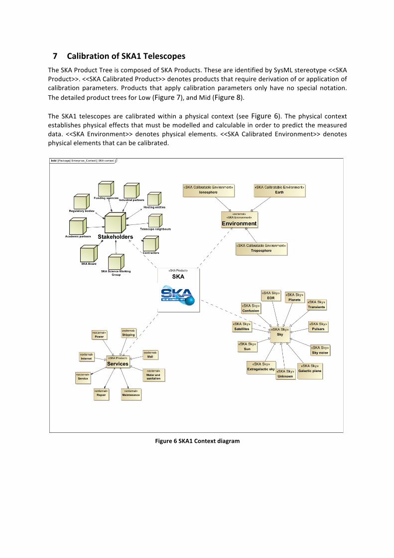
7 Calibration of SKA1 Telescopes The SKA Product Tree is composed of SKA Products. These are identified by SysML stereotype <<SKA Product>>. <<SKA Calibrated Product>> denotes products that require derivation of or application of calibration parameters. Products that apply calibration parameters only have no special notation. The detailed product trees for Low (Figure 7), and Mid (Figure 8). The SKA1 telescopes are calibrated within a physical context (see Figure 6). The physical context establishes physical effects that must be modelled and calculable in order to predict the measured data. <<SKA Environment>> denotes physical elements. <<SKA Calibrated Environment>> denotes physical elements that can be calibrated.
Figure 6 SKA1 Context diagram

Document No.: Revision: Date:
SKA-‐TEL-‐SKO-‐0000000 D 2015-‐04-‐08
UNRESTRICTED Author: T.J. Cornwell
Page 22 of 28
7.1 Calibration of SKA1_Low
7.1.1 Overview
Figure 7 Low Product Tree

Document No.: Revision: Date:
SKA-‐TEL-‐SKO-‐0000000 D 2015-‐04-‐08
UNRESTRICTED Author: T.J. Cornwell
Page 23 of 28
Products/Environments to be calibrated: • Ionosphere • Lower Inner Station
o Low Antenna o Low frequency LNA o Low Analog Transmission
• Lower Outer Station o Low Antenna o Low frequency LNA o Low Analog Transmission
• Low Synchronisation and Timing Correction of calibration:
• Low Telescope Manager • Low Station Beamformer • Low Synchronisation and Timing • Low Science Data Processor
7.1.2 Sketch of calibration
Of these, the calibration of the ionosphere is the most troublesome at the frequencies at which SKA1-‐Low operates. From LOFAR we know that the ionosphere above each station changes on a time of 5 to 10s. Fortunately the sky is bright and there usually exists a background sky composed of compact sources that can be used to solve for the phase screen in some parametric or pixelated form. This screen can then be applied to the visibility data using AW-‐Projection and related techniques. The compute load is very high, though, and for LOFAR one cycle of calibration can take many months. Anecdotally, we know that while this approach works for LOFAR, it does not allow the noise level to be reached. Since SKA1-‐Low is 16 times larger than LOFAR, it seems that successful calibration of LOFAR is a necessary but by no way sufficient condition for SKA1-‐Low to be calibrateable. Calibration of Low is an Extreme risk in the Project risk register. In addition, computation of the calibration is also an Extreme risk. The calibration of the stations requires solving for the gains of the 256x2 LNAs in each station. This is done in two stages:
• Antenna-‐to-‐antenna (including LNA-‐to-‐LNA) consistency is ensured by solving for gains from the autocorrelation matrix of the signals, measured across coarse frequency channels in a round robin that repeats every few minutes. It is not known currently how often this calibration will have to be repeated. The data and compute loads are moderate.
• Station-‐to-‐station consistency is assured by self-‐calibration of the station scalar gains on a few minute timescale.

Document No.: Revision: Date:
SKA-‐TEL-‐SKO-‐0000000 D 2015-‐04-‐08
UNRESTRICTED Author: T.J. Cornwell
Page 24 of 28
7.2 Calibration of SKA1_Mid
7.2.1 Overview
Figure 8 Mid Product Tree
Document No.: Revision: Date:
SKA-‐TEL-‐SKO-‐0000000 D 2015-‐04-‐08
UNRESTRICTED Author: T.J. Cornwell
Page 25 of 28
Products/Environments to be calibrated:
• Troposphere • Ionosphere • MeerKATProxy (the notional interface to a MeerKAT antenna) • Mid Antenna Station
o Mid Dish o SPF and LNAs o Mid Analog Transmission
• Mid Synchronisation and Timing
Correction of calibration: • Mid Telescope Manager • Mid Dish Station
o Mid Dish • Mid Array Beamformer • Mid Synchronization and Timing • Mid Science Data Processor
7.2.2 Sketch of calibration
The troposphere can be solved for as part of Mid station-‐to-‐Mid station self-‐calibration. This type of processing is very familiar from JVLA and eMERLIN, and presents little risk.

8 Modifications to Statements of Work As part of the implementation of this framework, some modifications to existing Statements of Work may be required. These will be negotiated between the consortia and SKAO.

9 Additional L1 requirements This calibration framework requires additional L1 requirements. These will be submitted as part of the ECP including this document as a reference document.
9.1 Missing L1 requirements
ID Requirement Status Parent Requirement Verification SKA1-‐SYS_REQ-‐????
Beamformer calibration: All beamformers shall accept calibration parameters for application during beamforming.
Proposed Test

10 The Way Forward The future developments are planned:
• Send for review and commentary by SDP and TM, initially (Done) • Modify and send for review and commentary by all Elements. • Discuss tentative assignments with those affected. • Consider if revised SOW’s are required. • Develop set of L1 requirements to be submitted as ECP • Connect this approach to the SysML model of the telescopes, including functional
and product level aspects. • Develop approach for both telescopes in more detail.
To develop the approach for each telescope, we will proceed via Calibration Consultations, inviting those with topical related information to advise on Best Practice. An example of how this works is given for SKA1-‐Low in Figure 9.
Figure 9 Plan for a Calibration Consultation for SKA1-‐Low, showing the input topics and the output models. The outcome will be a Calibration Plan for each telescope, outlining the methods for establishing context, specifying product level models, and defining calibration processes.
Calibrateability Antenna,Characterisation
Station,calibration
Telescope,calibration
Pulsar Ionospheric,modeling
EOR,detection
Imaging
Low,Antenna X X X X X XLow,Frequency,LNA X X X XLow,Analog,Transmission X X X XLow,Station,Configuration X X X X
OUTPUTS Low,Synchronisation,and,Timing X X X XLow,Configuration X X X XLow,BeamformerLow,CorrelatorLow,Imaging,Processor X XIonosphere X X X X X XGalactic,Plane X X
Context Extragalactic,Sky X X XConfusion X X,RFI,, X X
INPUTS


![INFRA SA Technical Response - SKA Telescope · The INFRA SA Technical Response responds to the SKA1 Baseline Design (as detailed in Applicable Document [AD 1] – SKA1 System Baseline](https://img.dokumen.tips/doc/110x75/5e1786d8f6b1154e0b272ecf/infra-sa-technical-response-ska-the-infra-sa-technical-response-responds-to-the.jpg)