Embed Size (px)
Citation preview

1060
3150
1/10
15
SK 135E & SK 175EMotor Soft Start with Reversing FunctionDistributed Control - Decentralized Technology
Intelligent Drivesystems
F3015

Table ofContents
Product Series Page
SK 135E & SK 175E Product Series 3
SK 135E & SK 175E Family Overview 4
Flexible Solutions SK 135E & SK 175E Product Features 6
AS Interface Connection 7
Application Functions 8
NORD CON 9
Flexible Mounting Positions 10
Assembly Diagram 12
Options Internal Customer Units 14
External Customer Units 15
Control Units 16
Status & Diagnostics 17
Drive Function Configuration 18
Flexible Plug-in Systems 20
System Connectors 21
Ordering Information General Specifications 22
Control Terminal Connection & Functions 23
Selection Guide 24
Nomenclature Examples 25
Ratings 26
Customer / Technology Unit Overview 28
Dimensions 30
2

Distributed ControlSoft Start Drives
3
Soft Start Drive Series SK 135E & SK 175EEliminate uncontrolled starting and mechanical strain on your drive components with the SK135E soft start drive family.
AC Motors that are connected directly to their power source exhibit a heightened power consumption during starting, stopping and can demand up to 7X of the rated motor current irrespective of load. This can create irregular starting and shut down behaviors as well as unneccessary strain on all components involved.
NORD has created a simple and economical solution to these unneccesary risks associated with running electric motors as your prime mover. The SK135E regulates the 3 major functions of a motor starter and controls them in order to protect your equipment and what you are moving while saving you money in the process.

Technical Configuration ofSK 135E & SK 175E - Sizes 1 & 2
SK 135E: Technical Configuration
SK 135E & SK 175E
0.33 - 5.0 hp @ 230V (0.25 - 3.75 kW)0.33 - 10.0 hp @ 400V (0.25 - 7.5 kW)
The products included in this family are best suited for controlled soft starts to help eliminate the mechanical strain and increased voltage used when it is unnececssary. It also simplifies forward and reverse functionality.
SK135E - SK 175E Basic Functions Control Signals2 Digital InputsE.G. For left/right release, fixed frequencies or the switching over of parameters.
2 Digital OutputsE.G. Reporting of errors or various limit values.
24V Power SupplyUse 24V-TU-XXX)Added without an additional connection.Seperate 24V can be supplied to multiple units.
Input Signal Conditioners4 Integrated PotentiometersUsed for controlling motor current, inhibit times, torque and ramp times.
Commisioning4 DIP SwitchesUtilized for automatic starting, phase sequencedetection as well as ramp down functionality.
4
Input Power/Frame Size MatrixFrame Size 3~200-240V 3~380-500VSize I 0.16 - 2 hp 0.33 - 4 hpSize II 3 - 5 hp 5 - 10 hpSize details on page 30.

SK 190E
NORD Distributed ControlProduct Overview
5
Description / Function SK135E/175E SK180E SK200E
Power range up to 10 hp up to 3 hp up to 30 hp
Typ
e Reversing, soft start - -
Frequency inverter / Soft Start Device -
Co
nfi
gu
rati
on Connection for PTC temperature sensor
Uniform parameter structure / error messages
Configuration via software parameterisation
Configuration via DIP switches and potentiometers -
Number of I/Os DIN / DOUT / AIN 2 / 2 / 0 3 / 2 / 2 4 / 2(1) / 2
Bra
ke
fun
ctio
ns Integrated electronic brake rectifier -
Integrated brake chopper - m**
Internal braking resistor - m** m
External braking resistor - m** m
Ho
usi
ng
/ V
ersi
on
Housing version SK 100E SK 100E SK 200E
Wall-mounting possible
Protection class (climate class) IP55 (3k3)
Protection class (climate class) IP66 (3k4) m m m
ATEX Zone 22-3D m m m
EMC rating: Radio interference suppression level (for motor mounting) C1 C1 C2
Leakage current (with active mains filter) < 20 mA < 16 mA > 30 mA
Pro
tect
ion PTC / I2t / Motor phase monitoring
Overvoltage trip / Undervoltage protection
Short-circuit / Earthing monitoring -
Dat
a /
Bu
s in
terf
ace
RS 232 PC diagnostic interface
Data storage via plug-in EEPROM - -
System bus -
Interface for bus coupling m m m
Fun
ctio
nal
ity
STO function - - m
Connection for incremental encoder (servo mode) - -
Posicon positioning mode - -
Sensorless current vector control (ISD control) -
Energy saving function: "Automatic flux optimisation" -
Control Power Included -
Standard Functions m Optional Functions ** Unavailable from 0 - 1.1 kW
6
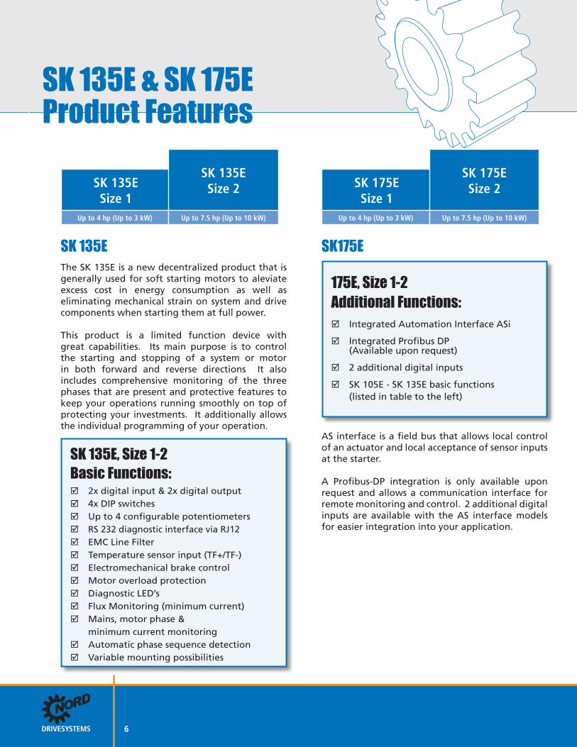
SK 135E & SK 175E Product Features
SK 135ESize 1
SK 135ESize 2
Up to 4 hp (Up to 3 kW) Up to 7.5 hp (Up to 10 kW)
SK 135E The SK 135E is a new decentralized product that is generally used for soft starting motors to aleviate excess cost in energy consumption as well as eliminating mechanical strain on system and drive components when starting them at full power.
This product is a limited function device with great capabilities. Its main purpose is to control the starting and stopping of a system or motor in both forward and reverse directions It also includes comprehensive monitoring of the three phases that are present and protective features to keep your operations running smoothly on top of protecting your investments. It additionally allows the individual programming of your operation.
SK 135E, Size 1-2Basic Functions: 2x digital input & 2x digital output 4x DIP switches Up to 4 configurable potentiometers RS 232 diagnostic interface via RJ12 EMC Line Filter Temperature sensor input (TF+/TF-) Electromechanical brake control Motor overload protection Diagnostic LED’s Flux Monitoring (minimum current) Mains, motor phase & minimum current monitoring Automatic phase sequence detection Variable mounting possibilities
SK 175ESize 1
SK 175ESize 2
Up to 4 hp (Up to 3 kW) Up to 7.5 hp (Up to 10 kW)
SK175E
175E, Size 1-2Additional Functions: Integrated Automation Interface ASi
Integrated Profibus DP (Available upon request)
2 additional digital inputs
SK 105E - SK 135E basic functions (listed in table to the left)
AS interface is a field bus that allows local control of an actuator and local acceptance of sensor inputs at the starter.
A Profibus-DP integration is only available upon request and allows a communication interface for remote monitoring and control. 2 additional digital inputs are available with the AS interface models for easier integration into your application.

AS Interface Connectionwith M12 Plug Connectors
7
Modern automation systems have a wide range of requirements. Not all of these requirements include the need for speed control. The SK135E offers increased motor protection for simple local control.
For network control the SK175E may be used with built-in AS Interface or the optional Profibus version. This allows a soft starter to be integrated into as a communication network for monitoring and control. The SK135E family of soft start products is a great addition to the NORD line of electronic products.
The supply voltage (power) is via the appropriate terminals according to the rating (3~230/460V). For the control unit of the SK175E and the AS interface, the supply is via the (yellow) AS interface cable. This eliminates the need for an additional AUX cable (black).
Versions with AS-i on board: AS interface on board
SK 175E Only
To connect the AS-i cable and any initiators, appropriate M12 plug connectors can be provided ex-works. These are color-coded in order to provide a definite assignment of functionalities in the field. The following versions can be selected as options.
AS interface connection • AS interface
• Optional M12- plug connector (yellow) for AS-i: SK TIE4-M12-AS1 (Part No. 275274502)
Connection for AS interface and initiators • AS interface
• Initiators (max. 4 x M12 connections possible, 2 with each digital input that is provided [2])
• Optional M12- plug connector (yellow) for AS-i: SK TIE4-M12-AS1 (Part No. 275274502)
• Optional M12 plug connector (black) for I/O: SK TIE4-M12-INI (Part No. 275274503)
Power(230V/400V)
AS interface
SK 175E, Size 1SK 175E, Size 2
Up to 4 hp (Up to 3 kW) Up to 7.5 hp (Up to 10 kW)

SK 135E & SK 175EApplication Functions
Application functions of the SK 135E & SK 175E
Variable Operating Characteristics• Pre-defined switch-off modes
• Variable starting and shut down ramps
• Boost function
Rectifier
EMC Filtering Mains EMC - Filter Class C1 (B)• All 230/400V devices have an integrated mains filter
• Also ideal for applications in a domestic environment, due to compliance with Class C1 (for motor mounting), or Class C2 (for wall mounting with motor cables up to 5 meters long)
• Suitable for personal protection due to low leakage current for operation with universal current FI circuit breakers
Commissioning• Commissioning via integrated DIP switches and potentiometers.
• No programming knowledge required
8
• Configuration via DIP switches and potentiometers• Integrated electronic brake rectifier• Choice of different shut down modes• < 20mA Leakage current• 2 Digital inputs and outputs
• On-Board ASi or Profibus interface• System plug connectors• ATEX zone 22-3D variants• Various control options

9
NORD CON
NORD CONNORD CON is the free operating software for controlling, programming and diagnosis of all NORD electronic products.
SK 135E/175E Interface ConnectionConnecting a SK135E or SK 175E to a PC/laptop is the most effective way to control your soft starter. Connection is accomplished via the RS232 diagnostic interface on top of the soft start device. The cable does not come standard with the unit but is available. We can provide a 10 foot sub D to RJ12 connector cable but needs to be ordered seperately. (Part Number 278 910 240)
ControlThe AC vector drive can be manually operated by means of a software window with all of the operating elements of a Controlbox. An enable signal can be given. The parameter settings can be adjusted and read. Parameters (information and error messages) can be viewed. Users therefore have a supporting aid for each commissioning.
ProgrammingWith a convenient overview, users can view and adjust each available parameter. By means of a print option complete parameter lists or lists of the changed values can be created. The finished data sets can be saved on the PC/laptop and archived for future use.
Diagnosis
The NORD CON oscilloscope function is a simple but very useful instrument for the optimal adjustment of a system. By means of line graphs, all characteristics (current, torque, etc.) can be recorded and analyzed. With these results, application-relevant settings can be fine-tuned to enable optimum operation. This is useful, e.g. for regulating the brake control or for lifting gear functions.

FlexibleMounting Possibilities
10
Wall-Mounting(with or without fan)
Motor Assembly
Soft Starter as a Motor or Wall Mount Option
Technology Box on the SK 135Eor Wall Mounted
Connected ViaSystem Bus Cable
OR
Adapter plate& Seal
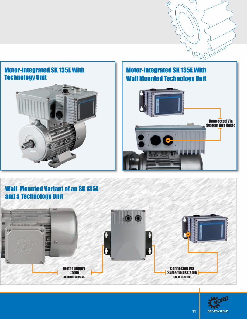
Wall Mounted Variant of an SK 135Eand a Technology Unit
Motor SupplyCable
(Terminal Box to 3L]
Connected ViaSystem Bus Cable
(3R to 5L or 5R]
11
Motor-integrated SK 135E With Technology Unit
Motor-integrated SK 135E With Wall Mounted Technology Unit
Connected ViaSystem Bus Cable

High PerformanceSoft Start DrivesSK 135E/175E Component Overview: Gearmotor
Adapter plate & seal
SK 135E/175E soft starter
SK 135E/175E motor adapter plate
Customer unit (internal)
Technology unit adapter
Technology units
Programming tools
SK 135E/175E wall-mount (bracket)
Technology unit wall-mount
Units can be operated with all standard asynchronous motors
Generously dimensioned for easy assembly of various system connectors
Motor or wall mounting
RoHS compliance"Lead free soldering"
UL Certification / cUL / CE
SK 135E & SK 175E Characteristics:
12
+

13
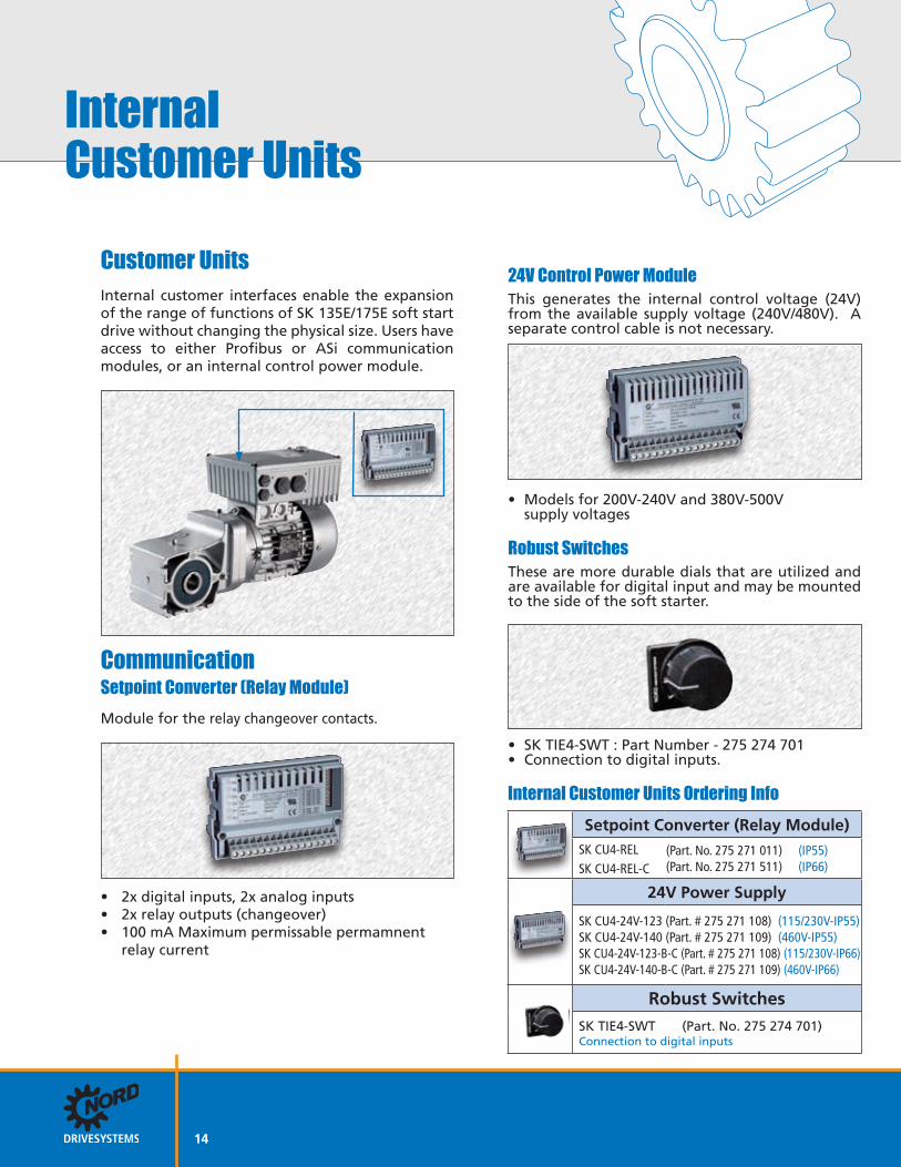
InternalCustomer Units
Customer Units
Internal customer interfaces enable the expansion of the range of functions of SK 135E/175E soft start drive without changing the physical size. Users have access to either Profibus or ASi communication modules, or an internal control power module.
CommunicationSetpoint Converter (Relay Module)Module for the relay changeover contacts.
• 2x digital inputs, 2x analog inputs• 2x relay outputs (changeover)• 100 mA Maximum permissable permamnent relay current
24V Control Power ModuleThis generates the internal control voltage (24V) from the available supply voltage (240V/480V). A separate control cable is not necessary.
• Models for 200V-240V and 380V-500V supply voltages
Robust SwitchesThese are more durable dials that are utilized and are available for digital input and may be mounted to the side of the soft starter.
• SK TIE4-SWT : Part Number - 275 274 701• Connection to digital inputs.
14
Internal Customer Units Ordering InfoSetpoint Converter (Relay Module)
SK CU4-REL SK CU4-REL-C
(Part. No. 275 271 011) (IP55)(Part. No. 275 271 511) (IP66)
24V Power Supply
SK CU4-24V-123 (Part. # 275 271 108) (115/230V-IP55) SK CU4-24V-140 (Part. # 275 271 109) (460V-IP55) SK CU4-24V-123-B-C (Part. # 275 271 108) (115/230V-IP66) SK CU4-24V-140-B-C (Part. # 275 271 109) (460V-IP66)
Robust Switches SK TIE4-SWT (Part. No. 275 274 701) Connection to digital inputs

ExternalCustomer Units
15
Variable Mounting
For the distributed control SK 135E soft starter, optional technology units are available. These units may be mounted directly on the device or separately on the machine frame or plant component. Communication systems both with & without connection facilities for sensors, actuators and control modules are available for applications using the SK 175E.
Technology unit mounted directly on the soft starter
Technology units for wall mounting
SK 135E as an Independent SystemFor independent applications, the SK 135E can be equipped with options which only require a power connection (e.g. 3~ 480V).
24V Control Power ModuleThis generates the internal control voltage (24V) from the available supply voltage (240V / 480V). A separate control power cable is not necessary.
• Can be used for 2 SK135E soft starters
Maintenance SwitchWith this unit, you may switch off the supply of power or motor voltage to a 135E and secure that unit against switching back on. This is very impor-tant when you performing service or repair.

ExternalCustomer Units
16
External Customer Units Ordering Information24V Power Supply
IP55 unit 115/230V: SK TU4-24V-123 (Part. No. 275 281 108)+ SK TI4-TU-NET (Part. No. 275 280 100)
IP66 unit 115/230V: SK TU4-24V-123-C (Part. No. 275 281 158)+ SK TI4-TU-NET-C (Part. No. 275 280 600)
IP55 unit 460V: SK TU4-24V-140 (Part. No. 275 281 109)+ SK TI4-TU-NET (Part. No. 275 280 100)
IP66 unit 460V: SK TU4-24V-140-C (Part. No. 275 281 159)+ SK TI4-TU-NET-C (Part. No. 275 280 600)
Maintenance Switch IP55 unit: SK TU4-MSW (Part. No. 275 281 123)+ SK TI4-TU-BUS (Part. No. 275 280 200)
IP66 unit: SK TU4-MSW-C (Part. No. 275 281 173)+ SK TI4-TU-BUS-C (Part. No. 275 280 700)
Operation, Display & DiagnosticsAccording to the application, there are different methods of controlling, programming or troubleshooting a SK 135E/175E soft start device.
• Parameter Box• Simple Box• PC/laptop with NORDCON software• Dip-switches
Parameter Box
Control panel and plain text display for text-controlled commissioning, programming and control of the soft starter. 5 data sets can be stored. Direct connection to a PC is possible via USB. This option is available as a handheld or panel mount version.
Simple Box
Control panel with 4-digit 7-segment display for rapid and direct programming and diagnosis.
Interface Converter
Signal converter from RS 485 to RS 232. This is used to connect a device with an RS 232 interface to another device with an RS 485 interface.
Control Units Ordering InfoParameter Box*
SK PAR-3H (Handheld) (275 281 014) + SKTIE4-RS485-RS232 (275 274 603)
Simple Box*
SK CSX-3H (Handheld) (275 281 013) + SKTIE4-RS485-RS232 (275 274 603)
Interface Converter
SK TIE4-RS485-RS232 (275 274 603)
* The interface connector is required to operate the control units with the SK 135E Series.
Control Units

17
SK 135E & SK 175EStatus & Diagnostics
Direct-access to diagnostic tools
A great advantage of a distributed control system is that the location of the soft starter is near the motor, which is extremely beneficial in large plant facilities. Therefore direct access to the system for monitoring and diagnosis is a great benefit. The diagnostic tools for the SK 135E are easily visible and accessible behind a transparent screw-on cover.
SK 135E - Sizes 1-21 . RS 232 diagnostic interface RJ 12 interface for connecting a cable to either a SimpleBox, ParameterBox or PC/laptop (NORDCON) for control, operation, programming and diagnosis. * Requires RS485 to RS232 interface converter.
DIP Switches for Analog Inputs DIP Switches on the SK135E are included and located internally.
SK 175E - Sizes 1-21 . RS 232 diagnostic interface RJ 12 interface for connecting a cable to either a SimpleBox, ParameterBox or PC/laptop (NORDCON) for control, operation, programming and diagnosis. * Requires RS485 to RS232 interface converter.
2 . Status-LEDs for device status and ASI status Status LEDs for device status and ASI status are visible through the site glass. They have a green and red component to indicate status or fault.
DIP Switches for Analog Inputs DIP Switches on the SK175E are included and located internally.
1 1 & 2
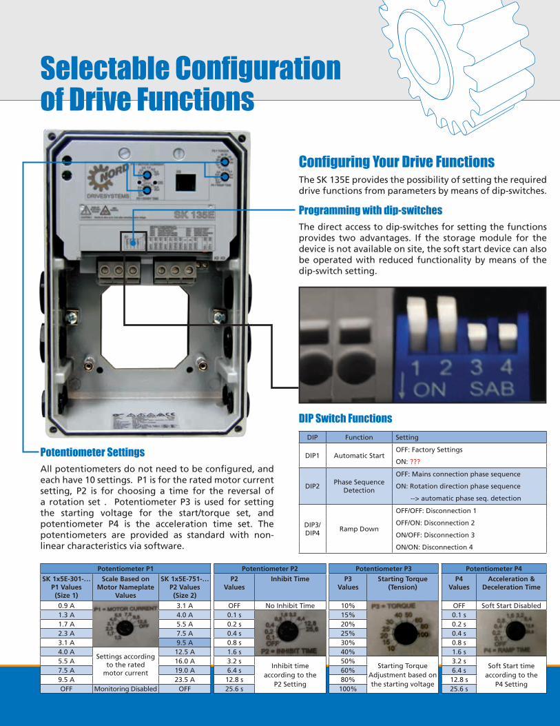
Selectable Configurationof Drive Functions
Potentiometer SettingsAll potentiometers do not need to be configured, and each have 10 settings. P1 is for the rated motor current setting, P2 is for choosing a time for the reversal of a rotation set . Potentiometer P3 is used for setting the starting voltage for the start/torque set, and potentiometer P4 is the acceleration time set. The potentiometers are provided as standard with non-linear characteristics via software.
Configuring Your Drive Functions The SK 135E provides the possibility of setting the required drive functions from parameters by means of dip-switches.
Programming with dip-switchesThe direct access to dip-switches for setting the functions provides two advantages. If the storage module for the device is not available on site, the soft start device can also be operated with reduced functionality by means of the dip-switch setting.
DIP Switch FunctionsDIP Function Setting
DIP1 Automatic StartOFF: Factory Settings
ON: ???
DIP2Phase Sequence
Detection
OFF: Mains connection phase sequence
ON: Rotation direction phase sequence
--> automatic phase seq. detection
DIP3/DIP4
Ramp Down
OFF/OFF: Disconnection 1
OFF/ON: Disconnection 2
ON/OFF: Disconnection 3
ON/ON: Disconnection 4
Potentiometer P1 Potentiometer P2 Potentiometer P3 Potentiometer P4SK 1x5E-301-…
P1 Values(Size 1)
Scale Based onMotor Nameplate
Values
SK 1x5E-751-…P2 Values (Size 2)
P2Values
Inhibit Time P3Values
Starting Torque(Tension)
P4Values
Acceleration &Deceleration Time
0.9 A
Settings according to the rated
motor current
3.1 A OFF No Inhibit Time 10%
Starting Torque Adjustment based on the starting voltage
OFF Soft Start Disabled1.3 A 4.0 A 0.1 s
Inhibit time according to the
P2 Setting
15% 0.1 s
Soft Start timeaccording to the
P4 Setting
1.7 A 5.5 A 0.2 s 20% 0.2 s2.3 A 7.5 A 0.4 s 25% 0.4 s3.1 A 9.5 A 0.8 s 30% 0.8 s4.0 A 12.5 A 1.6 s 40% 1.6 s5.5 A 16.0 A 3.2 s 50% 3.2 s7.5 A 19.0 A 6.4 s 60% 6.4 s9.5 A 23.5 A 12.8 s 80% 12.8 sOFF Monitoring Disabled OFF 25.6 s 100% 25.6 s

19
Programming with the terminal stripThe drive can be operated from the terminal strip. You need to order or provide local operator controls. PLC outputs can supply operation command or field bus control. The control terminal block includes digital inputs, PTC inputs and digital outputs. Push in terminals are provided in order to eliminate the use of tools to attach wires to the block. The terminals are programmable and preprogrammed for the most common functions. If the terminal function definitions need to be adjusted, Nordcon, or an external control unit will be required.
Commissioning of the AS InterfaceOn SK 175E models that come standard with AS interface, connection of the AS interface cable is made via terminals of the terminal bar and can also optionally be made via an appropriately labelled M12 flanged plug contact (yellow).
The position of ASI connecting strip X4 and jumpers used for terminating the bus terminating resistor and are only available on the SK 175E models.
Optional Profibus SK 175E ModelOn the SK 175E models that are paired with Profibus, the bus terminating resistor is terminated with the use of jumpers. The bus terminating resistor must always be the first and last bus subscriber of the PROFIBUS DP.
The position of PROFIBUS connecting strip X4 and jumpers used for terminating the bus terminating resistor are only available on the SK 175E models.

20
FlexiblePlug-in Systems
System Connecters
The screw connections on the SK 135E unit and technology unit base may be fitted with system connectors for power, motor output, control as well as bus signals.
Option Slots for SK TI4 Units or Power Plugs
or M25 Screw Connections
or M25 Screw Connection
or M16 Screw Connection
or M16 Screw Connection
Option Slots for the SK TI4-TU-... Technology Units
M16 Screw Connection
M16 Screw Connection
M16 Screw Connection
M16 Screw Connection
or M20 Screw Connection
Connection / Technology Unit
System Connectors for Option SlotsOperation
SK TIE4-SWT Switch L-O-R or Bus System
SK TIE4-M12-AS1 AS Interface or
(Adapter Unit)
- (Connection Unit)
SK TIE4-M12-ASI-AUX AS Interface
SK TIE4-M12-PBR Profibus
Control Signals
SK TIE4-M12-POW 24V Supply ???
Adapter Unit / Soft Start
Connection / Customer Unit
Customer UnitMounting*

21
SystemConnectors
Connector Type Description Part Number
Powe
r
SK TIE4-HAN-Q5-LE-LAPower in/out (HANQ5)
400V 16A275 274 110
SK TIE-HAN10E-M2B-LAPower Output (HAN10E LA 2BUE)
500V 16A275 135 010
SK TIE4-HAN10E-M1B-LEPower Input (HAN10E LE 1BUE)
500V 16A275 135 070
SK TIE4-HAN10E-M2B-LEPower Input (HAN10E LE 2BUE)
500V 16A275 135 000
SK TIE4-HAN10E-M2B-MAMotor Output (HAN10E MA 2BUE)
500V 16A275 135 020
SK TIE4-HANQ8-K-LA-MXPower Output (HQ8 LA)
500V 16A275 135 040
SK TIE4-HANQ8-K-LE-MXPower Input (HQ8 LE)
500V 16A275 135 030
SK TIE4-HANQ8-K-MA-MXMotor Output (HQ8 MA)
500V 16A275 135 050
Other versions available upon request
Bus S
yste
m
SK TIE4-M12-ASI AS interface (M12) 275 274 502
SK TIE4-M12-ASI-AUX AS interface (M12, AUX) 275 274 513
SK TIE4-M12-PBR Profibus (M12) 275 274 500
Cont
rol S
igna
ls SK TIE4-M12-INI Initiator (M12) 275 274 503
SK TIE4-M12-POW 24V Supply (M12) 275 274 507
SK TIE4-M12-INP 24V Supply & Initiator (M12) 275 274 516
SK TIE4-M12-M16 Extension from M12 to M16 275 274 510
System Connector Flexibility The screw connections on the respective adapter unit can be fitted with system plug connectors for power, motor output, control and bus signals.

22
General Specifications
Function Specification
Starter type SK 135E & SK 175E- -301-340-B -301-340-B -751-340-B -751-340-B
Connected Voltage 240V 10% 480V 10% 240V 10% 480V 10%
Power[kW] 0.25 to 1.5 0.25 to 3.0 2.2 to 4.0 4.0 to 7.5
[hp] 0.33 to 2.0 0.33 to 4.0 3.0 to 5.0 5.0 to 10
Input / Output voltage 3~ 200 V … 500 V, -10% / +10%, 47 ... 63 Hz
Typical Amps [A] 7.5 16
Standard
• Integrated mains filter Class C1, for motor-mounting or 10m cable length for wall-mounting Class C2 for wall-mounting with motor cable length up to 100m
• Low leakage current (< 20 mA)
• Consistent and user-friendly parameter structure
Typical overload capacity 150% for 120 s up to 360 s (adjustable)
Protective measures against overtemperature, overvoltage/undervoltage, overload
Motor temperature monitoring Temperature sensor (PTC), temperature monitor (bimetal), I2t- motor
Standard interfacesStandard: RS 232 (Commissioning and diagnosis) (Single-Slave)Optional: Profibus DP or AS-interface
Digital input2x DIN, 2xDOUT, min 0-5V, max 14-30V, Resistant Current (Ri) = 9.5 Ω, Capacitance Current (Ci) = 10nF, Cycle Time = 4 ms
Ambient temperature -25°C...+50°C (S1- 100% ED), -25°C... +60°C (S3 - 70% ED 10 min)
Version Motor mounted, wall mounted
Protection class IP55 optional IP66
IP66 measures:• Coated aluminium components • Coated PCBs
• Low pressure test • Membrane valve
Operating Altitude Adjustments
Up to 1,000m -1,000 - 4,000m -2,000 - 4,000m -
No Power Reduction0.25% per 100m up to 2,000m (Overvoltage category 3)External overvoltage protection at the mains input required (Overvoltage category 2)
Environmental ConditionsTransport (IEC 60721-3-2):Operation (IEC 60721-3-3):
Vibration 2M2Vibration 3M7;Climate 3K3 (IP55) 3K4 (IP66) / IP69K
Terminals
Mains / Motor 10mm2 Flexible with ferrule
Terminal Screw Tightening Torque = 1.2-1.5 NmBrake Resistor 10mm2 with rigid cable
Control Part 1.5mm2 with ferrule 1.5mm2
RS232 Terminal RS232 1 x RJ12 (6 pin)

23
Control TerminalConnection & Functions
SK 135E / SK 175E Terminal Diagrams
All control Cables (including the thermistor) must be installed seperately from the mains and motor cables in order to prevent interference to the device.
If the cables are laid in parallel, a minimum distance of 20cm must be maintained with cables that carry a current greater than 60V. The minimum distance may be reduced by screening the cables or with the use of earthed metal partitions within the cable conduits
1 2 3 4 5 6
X6
L1 L2 L3 U V W
POWER MOTOR
P1 - Motor Current
P2 - Inhibit Time
P3 - Torque
P4 - Ramp
79 80
X1 X2 X3
44 44 40 40 44 21 22 40 1 3 40 39 38
X5S1
DIP
1D
IP 2
DIP
3
DIP
4
X4
40 C2 C1 43
85/8
184
/82
SK 135E / SK 175E Overview
X6
P1
P2
P3
P4
S1
1234
L1
L2
L3
POWER444440404421224013
40
3938
24V INPUT (24V)24V INPUT (24V)GROUND (GND)GROUND (GND)24V INPUT (24V)DIGITAL INPUT 1 (DI1)DIGITAL INPUT 2 (DI2)GROUND (GND)DIGITAL OUTPUT 1 (DO1)DIGITAL OUTPUT 2 (DO2)GROUND (GND)
PTC RESISTOR INPUT (TF-)PTC RESISTOR INPUT (TF+)
7980
BRAKE CONTROL (MB+)BRAKE CONTROL (MB-)
X1
X5
X3X2
U V W
MOTOR
N/A (-)
N/A (-)
Bus Signal Reference potential (GND) Data Cable (RS232 TXD)
Data Cable (RS232 TXD)
Output Voltage (+24V)
123456
40C2C1438584
GROUND (GND)DIGITAL INPUT 4 (DIN4)DIGITAL INPUT 3 (DIN3)
24V OUTPUT (VO/24V)ASI- (ASI-)
ASI+ (ASI+)
X4
SK175E ASi Model Connections and functions SK175E Profibus Model Connections and functions
SK135E Connections and functions
X6
P1
P2
P3
P4
S1
1234
L1
L2
L3
POWER
444440404421224013
40
3938
24V INPUT (24V)24V INPUT (24V)GROUND (GND)GROUND (GND)24V INPUT (24V)DIGITAL INPUT 1 (DI1)DIGITAL INPUT 2 (DI2)GROUND (GND)DIGITAL OUTPUT 1 (DO1)DIGITAL OUTPUT 2 (DO2)GROUND (GND)
PTC RESISTOR INPUT (TF-)PTC RESISTOR INPUT (TF+)
7980
BRAKE CONTROL (MB+)BRAKE CONTROL (MB-)
X1X5
X3X2
U V W
MOTOR
N/A (-)
N/A (-)
Bus Signal Reference potential (GND) Data Cable (RS232 TXD)
Data Cable (RS232 TXD)
Output Voltage (+24V)
123456
X6
P1
P2
P3
P4
S1
1234
L1
L2
L3
POWER444440404421224013
40
3938
24V INPUT (24V)24V INPUT (24V)GROUND (GND)GROUND (GND)24V INPUT (24V)DIGITAL INPUT 1 (DI1)DIGITAL INPUT 2 (DI2)GROUND (GND)DIGITAL OUTPUT 1 (DO1)DIGITAL OUTPUT 2 (DO2)GROUND (GND)
PTC RESISTOR INPUT (TF-)PTC RESISTOR INPUT (TF+)
7980
BRAKE CONTROL (MB+)BRAKE CONTROL (MB-)
X1
X5
X3X2
U V W
MOTOR
N/A (-)
N/A (-)
Bus Signal Reference potential (GND) Data Cable (RS232 TXD)
Data Cable (RS232 TXD)
Output Voltage (+24V)
123456
40C2C1438182
GROUND (GND)DIGITAL INPUT 4 (DIN4)DIGITAL INPUT 3 (DIN3)
24V OUTPUT (VO/24V)PBR-A (PBR-A)PBR-B (PBR-B)
X4

SK 135E & SK 175ESelection Guide
(if required)
Technology Unit-Specific Option SelectionTU-Specific Option Protection Class*
SK TU4 -
* Applies only to external "TU4" units
Fieldbus, I/O Extension module
24V-123: Internal 24V mains unit 1~230V
24V-140: Internal 24V mains unit 1~460V
MSW: Maintenance Switch
Protection Class
Blank: IP55
-C: IP66
(Required for all "SK TU-XXX" modules)
Technology Unit Adapter SelectionAssembly Adapter for TU4* Protection Class*
SK TI4-TU-
* Applies only to external "TU4" units
Assembly Adapter for TU4 Technology Units
NET: For the 24V Technology Unit
MSW: For the MSW Technology Unit
Protection Class
Blank: IP55
-C: IP66
(If required)
Wall Mount AdapterSelection Code for Adapter
SK TIE4-WMK-
Wall Mount Adapter Code
1: For drive frame sizes 1 & 2
Notes• Only 1 Internal CU4 customer unit may be installed per drive (with the exception of the SK CU4-POT).• Only one External TU4 technology unit (or SK CU4-POT) may be installed per drive.
Soft Start SelectionSeries kW Ratings Input Voltage Protection Class
SK E- -
Series
135: Basic
175: Basic + AS Interface
kW Rating
301: 3.0 kW (5 hp)
751: 7.5 kW (10 hp)
Input Voltage
340-B: 200-240V, 3-phase (0.25 - 1.1 kW)
340-B: 380-480V, 3-phase (0.25 - 2.2 kW)
Protection Class
Blank: IP55
-C: IP66
(if required)
Programmer/Operation Device
SK CSX-3H: Simple Box (LED Display)
SK PAR-3H: Parameter Box (LCD Plain Language Display)
RJ12-SUB/D: PC Cable for NORDCON software
(if required)
Customer Unit SelectionFieldbus/IOE
Option Protection Class M12 ConnectionOption
SK CU4
Fieldbus, I/O Extension Module
REL: Internal Setpoint Converter (Relay Module)
24V-123: Internal 24V mains unit 1~115/230V
24V-140: Internal 24V mains unit 1~400V
Protection Class
Blank: IP55
-C: IP66
M12 Connectors for Module I/O
Blank: Not Required
M12: M12 Connector Required
24

NomenclatureExamples
25
Adapter Unit - Technology Unit SK TIE4 – TU – SWT – (C–WMK–1)
IP protection Class:Standard = IP55, C = "Coated" IP66
Wall Mounting Kit: -1 = SI + II
Suitable Device Types: RS485-RS232 = Interface ConverterSWT = Robust switches
Group: TU = Technology UnitDevice Series: SK TI4 = Adapter unit SK TIE4
For I/O Extension Module SK TU4 – 24V – (C)
IP protection Class standard = IP55, C = "Coated" IP66
Option Type: 24V = 24V Module MSW = Maintenance Switch
Option Series: TU4 = External Technology Unit CU4 = Internal Customer Unit
Soft Start - Basic Device SK 175E – 751 – 340 – B – (ASI) – (C)
Number of Mains Phases3xx 3~phase
Radio Interference Filter: O = Without, B = Class B1
IP protection Class:standard = IP55, C = "Coated" IP66
Mains Voltage:x40 = 200-500V
Digits before decimal point for power: 0 = 0.xx, 1 = 0x.x0, 2 = 0xx.0Device nominal power: 301 = 3.0kW, 751 = 7.5kW
Device Series: SK 135E or SK 175E
Device version:ASI = integrated AS interfacePBR - Integrated Profibus interface
Connection Cables - Power SK TIE4 – HANQ5 – LE-LA
LE-LA : Power In/Out (HQ5)
K-LE : Power Input (HQ8)
K-LA : Power Output (HQ8)
K-LA-MX : Power Output (HQ8)K-LE-MX : Power Input (HQ8)
K-MA-MX : Motor Power Output (HQ8)
M1B-LE : Power Input (H10 1BUE)
M1B-LA : Power Output (H10 1BUE)
M2B-LE : Power Input (H10 2BUE)
M2B-LA : Power Output (H10 2BUE)
M2B-MA :Motor Power Output (H10 2BUE)
Plug Type: HANQ5 HANQ8 HAN10E
Device Series: SK TI4 = Adapter unit SK TIE4
Connection Cables - Control Signals SK TIE4 – M12 – INI
INI : InitiatorPOW : 24V SupplyINP : 24V Supply & Initiator
Plug Type: M12
Device Series: SK TI4 = Adapter unit SK TIE4

SK 135E & SK 175ESoft Start Device Ratings
AC Vector Drive typeSK 1xxE...
SK135E
SK175E
Mains voltage Output voltage Nominal motor power
Typical input current
Nominal output current
[kW] [hp] 3 ~ rms [A] rms [A]
3 ~ 2
00 ...
240V
-301-340-B (-C)
3 ~ 200...240V -/+10%
47...63Hz
3 ~ AC0V up to the
mains voltage
0.25 0.33 7.5 7.5
-301-340-B (-C) 0.37 0.50 7.5 7.5
-301-340-B (-C) 0.55 0.75 7.5 7.5
-301-340-B (-C) 0.75 1.0 7.5 7.5
-301-340-B (-C) 1.1 1.50 7.5 7.5
-301-340-B (-C) 1.5 2.0 7.5 7.5
-751-340-B (-C) 2.2 3.0 16.0 16.0
-751-340-B (-C) 3.0 5.0 16.0 16.0
-751-340-B (-C) 4.0 7.5 16.0 16.0
-751-340-B (-C) 7.5 10.0 16.0 16.0
3~38
0 ... 5
00V
-301-340-B (-C)
3 ~ 380...480V - 20% / +10%
47...63Hz
3 ~ AC0V up to the
mains voltage
0.25 0.33 7.5 7.5
-301-340-B (-C) 0.37 0.50 7.5 7.5
-301-340-B (-C) 0.55 0.75 7.5 7.5
-301-340-B (-C) 0.75 1.0 7.5 7.5
-301-340-B (-C) 1.1 1.50 7.5 7.5
-301-340-B (-C) 1.5 2.0 7.5 7.5
-301-340-B (-C) 2.2 3.0 16.0 16.0
-751-340-B (-C) 4.0 5.0 16.0 16.0
-751-340-B (-C) 5.0 7.5 16.0 16.0
-751-340-B (-C) 7.5 10.0 16.0 16.0
Standard - IP55 (-C) - IP66 - Available
26

AC Vector Drive typeSK 1xxE...
SK135E
SK175E
Mains voltage Output voltage Nominal motor power
Typical input current
Nominal output current
[kW] [hp] 3 ~ rms [A] rms [A]
3 ~ 2
00 ...
240V
-301-340-B (-C)
3 ~ 200...240V -/+10%
47...63Hz
3 ~ AC0V up to the
mains voltage
0.25 0.33 7.5 7.5
-301-340-B (-C) 0.37 0.50 7.5 7.5
-301-340-B (-C) 0.55 0.75 7.5 7.5
-301-340-B (-C) 0.75 1.0 7.5 7.5
-301-340-B (-C) 1.1 1.50 7.5 7.5
-301-340-B (-C) 1.5 2.0 7.5 7.5
-751-340-B (-C) 2.2 3.0 16.0 16.0
-751-340-B (-C) 3.0 5.0 16.0 16.0
-751-340-B (-C) 4.0 7.5 16.0 16.0
-751-340-B (-C) 7.5 10.0 16.0 16.0
3~38
0 ... 5
00V
-301-340-B (-C)
3 ~ 380...480V - 20% / +10%
47...63Hz
3 ~ AC0V up to the
mains voltage
0.25 0.33 7.5 7.5
-301-340-B (-C) 0.37 0.50 7.5 7.5
-301-340-B (-C) 0.55 0.75 7.5 7.5
-301-340-B (-C) 0.75 1.0 7.5 7.5
-301-340-B (-C) 1.1 1.50 7.5 7.5
-301-340-B (-C) 1.5 2.0 7.5 7.5
-301-340-B (-C) 2.2 3.0 16.0 16.0
-751-340-B (-C) 4.0 5.0 16.0 16.0
-751-340-B (-C) 5.0 7.5 16.0 16.0
-751-340-B (-C) 7.5 10.0 16.0 16.0
Standard - IP55 (-C) - IP66 - Available
27

Operator Interface OptionType Part Numbers Description Data
ParameterBoxSK PAR-3H
275 281 014 (Handheld)
Control panel and plain text display for text-controlled commissioning, programming and control of the AC vector drive.
Plain text display6 languages
5 data sets can be stored
SimpleBoxSK CSX-3H 275 281 013 (Handheld)
Control panel with 4-digit 7-segment display for rapid and direct programming and diagnosis.
4-digit, 7-segment displayNo data sets can be stored
RS485 - RS232Connector 275 274 603
Connection cable for converting the RS 232 format from the SK135/SK175 units to the RS485 format on the above mentioned keypads
RJ12 RS485 plug - RJ12 RS232 Plug with a short cable to connect the keypad to the SK135E/SK175E.
Customer UnitsTechnology Units &Operator Interfaces
Customer Units OptionType Part Numbers Description Data
COM
M Relay Output ModuleSK CU4-REL
275 271 011 (IP55)275 271 511 (IP66) Module for relay changeover contacts. 2x digital inputs, 2x relay outputs
100mA (≤30 VDC) Max permissable relay current
24V
Cont
rol
pow
er 24V mains unitSK TU4-24V-123-BSK TU4-24V-140-B
275 281 108 (230V - IP55)275 281 158 (230V - IP66)275 281 109 (460V - IP55)275 281 159 (460V - IP66)
This generates the internal control voltage (24V) from the available supply voltage (240V / 480V).
Mains unit 1~ 240V 24V, 1~ 480V 24V, 1x analog input, 1x pulse output
Can also be used for 2 devices
28
Technology Units OptionType Part Numbers Description Data
Dis
conn
ect
Disconnect (Maint. Switch)SK TU4-MSW
SK TU4-MSW-C
275 281 123 (IP55)275 281 173 (IP66) Lockable Service/Repair Switch
3 LEDs for Active Phases16Amps Max permissable current
24V
Cont
rol
pow
er 24V mains unitSK TU4-24V-123-BSK TU4-24V-140-B
275 281 108 (230V - IP55)275 281 158 (230V - IP66)275 281 109 (460V - IP55)275 281 159 (460V - IP66)
This generates the internal control voltage (24V) from the available supply voltage (240V / 480V).
Mains unit 1~ 240V 24V, 1~ 480V 24V, 1x analog input, 1x pulse output
Can also be used for 2 devices

Operator Interface OptionType Part Numbers Description Data
ParameterBoxSK PAR-3H
275 281 014 (Handheld)
Control panel and plain text display for text-controlled commissioning, programming and control of the AC vector drive.
Plain text display6 languages
5 data sets can be stored
SimpleBoxSK CSX-3H 275 281 013 (Handheld)
Control panel with 4-digit 7-segment display for rapid and direct programming and diagnosis.
4-digit, 7-segment displayNo data sets can be stored
RS485 - RS232Connector 275 274 603
Connection cable for converting the RS 232 format from the SK135/SK175 units to the RS485 format on the above mentioned keypads
RJ12 RS485 plug - RJ12 RS232 Plug with a short cable to connect the keypad to the SK135E/SK175E.
Customer Units OptionType Part Numbers Description Data
COM
M Relay Output ModuleSK CU4-REL
275 271 011 (IP55)275 271 511 (IP66) Module for relay changeover contacts. 2x digital inputs, 2x relay outputs
100mA (≤30 VDC) Max permissable relay current
24V
Cont
rol
pow
er 24V mains unitSK TU4-24V-123-BSK TU4-24V-140-B
275 281 108 (230V - IP55)275 281 158 (230V - IP66)275 281 109 (460V - IP55)275 281 159 (460V - IP66)
This generates the internal control voltage (24V) from the available supply voltage (240V / 480V).
Mains unit 1~ 240V 24V, 1~ 480V 24V, 1x analog input, 1x pulse output
Can also be used for 2 devices
29
Technology Units OptionType Part Numbers Description Data
Dis
conn
ect
Disconnect (Maint. Switch)SK TU4-MSW
SK TU4-MSW-C
275 281 123 (IP55)275 281 173 (IP66) Lockable Service/Repair Switch
3 LEDs for Active Phases16Amps Max permissable current
24V
Cont
rol
pow
er 24V mains unitSK TU4-24V-123-BSK TU4-24V-140-B
275 281 108 (230V - IP55)275 281 158 (230V - IP66)275 281 109 (460V - IP55)275 281 159 (460V - IP66)
This generates the internal control voltage (24V) from the available supply voltage (240V / 480V).
Mains unit 1~ 240V 24V, 1~ 480V 24V, 1x analog input, 1x pulse output
Can also be used for 2 devices

DimensionsMotor Dimensions with SK 135E / SK 175E Motor Mounted AC Vector Drive
AC Vector Motor Width Length Weight
Drive Size P TW L TL AB1 (no motor)
[in] [in] [in] [in] [in] [lbs]
Size 1
71S/L 5.71
6.06
8.43
8.70
6.99*
4.4180S/L 6.50 9.29 6.75
90S/L 7.20 9.88/10.87 6.95
100L/LA 7.91 12.05 7.30
Size 2
80S/L 6.50
6.06
9.29
8.70
7.62**
4.41
90S/L 7.20 9.88/10.87 7.81**
100L/LA 7.91 12.05 8.25**
112M/MA 8.98 12.83 8.64**
132S/M 10.47 14.69/16.18 8.52
* Includes additional adapter and seal (additional 18mm) part # 275119050
** Includes additional adapter and seal (additional 20mm) part # 275274321
30
TL
P
TW
AB1
L

Device Type Part Number Wall Mounting Total Weight
Size SKTIE4 WMK-1 Approx.
g2 d e Ø [lb]
Size 1 SK TIE4-WMK-1 275 274 000 4.45 2.52 7.087 0.217 1.32
Size 2 SK TIE4-WMK-1 275 274 001 4.55 2.52 7.087 0.217 1.32
SK 135E / SK 175E Wall Mount Dimensions
31
e
d
p2
g2
e
d
p2
g2
e
d
p2
g2

ProductOverview
1060
3150
1/10
15
NORD Gear Corporation National Customer Service Toll-Free: 888.314.6673
WESTCorona, CA (Los Angeles) Phone: 951.393.6565
MIDWESTWaunakee, WI (Madison)Phone: 608.849.7300
EASTCharlotte, NC Phone: 980.215.7575
CANADABrampton, ON (Toronto) Phone: 905.796.3606
NORD Gear Limited Toll-Free in Canada: [email protected]
HELICAL IN-LINE - Foot or Flange Mount - Torque up to 205,000 lb-in - Gear ratios – 1.82:1 to over 300,000:1 NORDBLOC®.1 HELICAL IN-LINE - Foot or Flange Mount - Torque up to 26,550 lb-in - Gear ratios – 1.88:1 to over 370:1 PARALLEL HELICAL CLINCHER™ - Shaft, Flange or Foot Mount - Torque up to 797,000 lb-in - Gear ratios – 4.26:1 to over 300,000:1 SCP SCREW CONVEYOR PACKAGE - Shaft, or Flange Mount - Torque up to 53,100 lb-in - Gear ratios – 4.32:1 to over 1500:1 RIGHT ANGLE HELICAL-BEVEL 2-STAGE - Foot, Flange or Shaft Mount - Torque up to 5,840 lb-in - Gear ratios – 4.1:1 to 70:1 RIGHT ANGLE HELICAL-BEVEL - Foot, Flange or Shaft Mount - Torque up to 283,000 lb-in - Gear ratios – 8.04:1 to over 300,000:1 RIGHT ANGLE HELICAL-WORM - Foot, Flange or Shaft Mount - Torque up to 27,585 lb-in - Gear ratios – 4.40:1 to over 300,000:1
UNICASE™ SPEED REDUCERS
NORDACAC VECTOR DRIVES
SK180E FAMILY- Distributed, simple speed control- 380-480V, 3-phase to 3.0 hp- 200-240V, 3-phase to 1.5 hp- 200-240V, 1-phase to 1.5 hp- 100-120V, 1-phase to 0.75 hp SK200E FAMILY- Distributed, high performance- 380-480V, 3-phase to 30 hp- 200-240V, 3-phase to 15 hp- 200-240V, 1-phase to 1.5 hp- 100-120V, 1-phase to 1 hp SK500E FAMILY- Compact, cabinet mount, high performance- 380-480V, 3-phase, to 125 hp- 200-240V, 3-phase, to 25 hp- 200-240V, 1-phase, to 3 hp- 100-120V, 1-phase, to 1.5 hp
MINICASE™ RIGHT ANGLE WORM - Foot, Flange or Shaft Mount - Torque up to 3,540 lb-in - Gear ratios – 5:1 to 500:1
FLEXBLOC™ WORM - Modular bolt-on options - Torque up to 4,683 lb-in - Gear ratios – 5:1 to 3,000:1 MAXXDRIVE™ LARGE INDUSTRIALGEAR UNITS PARALLEL HELICAL - Modular bolt-on options - Torque up to 2,027,000 lb-in - Gear ratios – 5:1 to 1,600:1 MAXXDRIVE™ LARGE INDUSTRIALGEAR UNITS HELICAL-BEVEL - Modular bolt-on options - Torque up to 2,027,000 lb-in - Gear ratios – 5:1 to 1,600:1
HIGH PERFORMANCEMOTORS & BRAKEMOTORS
INVERTER/VECTOR DUTY- Standard or Energy Efficient- Integral, NEMA or Metric IEC- 1/6 to 250 hp
UNICASE™ SPEED REDUCERS