Embed Size (px)
Citation preview
20211020 We reserve the right to alter specifications.
SILVER C
19
Prerequisites for Sizing ..................................................................................................... 21SILVER C RX, One-piece air handling units with rotary heat exchanger ....................... 22SILVER C PX, One-piece air handling units with plate heat exchanger......................... 80SILVER C CX, One-piece air handling units with coil heat exchangers........................ 127SILVER C SD, Supply air and extract air handling units ................................................ 140
Sizing, installation, dimensions and weights
Contents
The charts and tables in this documentation are intended for
use as a general survey.
Exact sizing can be carried out in the AHU Design air handling unit
selection program.

SILVER C
We reserve the right to alter specifications. 2021102020

20211020 We reserve the right to alter specifications.
SILVER C
21
Acoustic calculationsThe sound emitted by Swegon products is measured accord-ing to the method defined in ISO 5136, the most widely used method in Europe. Acoustic measurements are sometimes taken using other methods.
The total sound power level LW, tot emitted from the fan outlet to the ducting can be read from each of the fan diagrams. The following formula can be used for breaking down the sound power level into octave bands: LW, ok = LW, tot + Kok.
Kok can be obtained from tables on the pages that follow.
Fan DiagramsThe SFPV diagram on the pages that follow shows the elec-tric power efficiency rating of the air handling unit calculated according to the procedure defined by Svensk Ventilation, the Swedish Association of Air handling Industries (V Publication 1995:1, Rev. 2000). The SFPV-value is calculated according to the V publication under the load conditions that exist when the air filters are clean.
SILVER C RX/PX/CX The SFPV diagrams and Extract air fan are calculated with the assumption that the supply air and extract air fans have the same airflow and available total pressure rise. The leakage and purging air flow and to the extra pressure drop in the extract air have been taken into consideration in order to ensure the cor-rect direction of air leakage at a pressure ratio that corresponds to a normal installation for a certain available pressure.
The Extract air fan and Supply air fan diagrams indicate the available total pressure rise to cover duct pressure drop and external functional sections, and total sound power level, LW, tot emitted to a connecting outlet duct, dB (Relative to 10-12 W), in the 125 – 8,000 Hz octave band frequencies.
The available pressure rise calculated for the design pressure drop across the ePM1 50% (F7) filter (supply air) and the ePM10 60% (M5) filter (extract air) respectively and with full face end connection panels (accessories) is specified in all the diagrams.
The blue broken line defines the limits of the numbered ranges (1,2,3,4) for particulars of the correction factors KOK in a separate table. Range 1 is the most favourable range from an acoustic point of view.
SILVER C SDThe Fan Charts indicate the total pressure rise to cover pos-sible internal total pressure losses for, e.g. filters, duct pressure drop and external functional sections, and total sound power level LW, tot emitted to a connecting outlet duct, dB (Relative to 10-12 W), in the 125 – 8,000 Hz octave band frequencies. The diagrams show air handling units with full face end connection panels (accessories).
The total pressure loss for an optional filter, ePM1 50% (F7)/ePM10 60% (M5), and coil heat exchangers (sizes 014-080) are specified in the lower diagram.
The blue broken line defines the limits of the numbered ranges (1,2,3,4) for particulars of the correction factors KOK in a separate table. Range 1 is the most favourable range from an acoustic point of view.
Prerequisites for Sizing
Sizing, installation, dimensions and weights

SILVER C
We reserve the right to alter specifications. 2021102022
Sizing, installation, dimensions and weights
Min. and max. airflowsThe flows specified refer to those that can be preset in the hand-held micro terminal. The practical flow limits are deter-mined by the external pressure drop.
* The integral attenuation of filters and rotary heat exchanger has been taken into account.** Total sound power level emitted to the surroundings is calculated as the sum of the levels
in the supply air and the extract air.
Correction factors, KOK , dB
Size Min. flow (For units operating in the airflow reg. mode)
Max. airflow
m3/h m3/s m3/h m3/s004 288 0,08 1620 0,45
Rangein
diagram
Octave band, no./mid-frequency, Hz
Sound path 1 2 3 4 5 6 7 8
63 125 250 500 1000 2000 4000 8000
To the outletduct
1 -1 -6 -6 -8 -7 -7 -12 -152 -1 -5 -8 -8 -7 -9 -13 -163 -1 -2 -6 -15 -14 -16 -22 -254 -2 -3 -5 -13 -13 -14 -20 -25
To the inletduct*
1 -6 -9 -12 -22 -31 -33 -38 -372 -7 -10 -17 -18 -29 -31 -37 -383 -6 -4 -14 -27 -35 -39 -44 -434 -7 -5 -12 -22 -34 -36 -42 -43
To unit’s surroundings**
1 -12 -20 -29 -29 -40 -40 -46 -462 -12 -19 -31 -29 -40 -42 -47 -473 -12 -16 -29 -36 -47 -49 -56 -564 -13 -17 -28 -34 -46 -47 -54 -56
2.5
2.0
1.5
1
23
4
123
4
70dB 75Lw,tot
8085
70dB 75Lw,tot
8085
Supply air fan
Extract air fan
SFPv
Air flow, m3/s
Ava
ilab
le t
ota
l pre
ssu
re r
ise,
Pa
Air flow, m3/h
Recommended working range for sizing.
Permissible operating range when the fan is controlled to operate at a lower speed. The lower limit for the air flow when the unit is operat-ing in the air flow regulation mode; see the black broken line in the diagram. If pressure regulation is used, the air flow can be regulated to zero, however this presupposes a certain static pressure drop in the ducting (approx. 50 Pa).
The air handling unit complies with requirements to Ecodesign 2016/2018.
The lower limit for the air flow when the unit is operating in the air flow regulation mode.
SILVER C RX, rotary heat exchanger, size 004, common casingSTE

20211020 We reserve the right to alter specifications.
SILVER C
23
380
76 76
45 45J
14 = =ø 400 ø 315
52
284 284
Sizing, installation, dimensions and weights
Rated data per fanMotor shaft power: 0.8 kW (0.41 kW)*, motor control system: 1 x 230 V, 50 Hz, rated 2.3 A *The motor control system limits the power of the take-off to the value specified.
Motor, heat exchanger55 W, 1 x 230 V, 50 Hz, max. perm. fuse protection: 10A
Clear space for inspectionA clear space of 800 mm should be provided in front of the unit and at least 200 mm should be provided above the junction hood.
Right-hand version
Left-hand version
Delivery and transport within the siteThe SILVER C RX 004 is produced in one single variant. All of its components are arranged at their given physical locations inside the air handling unit. The air handling unit is supplied on a wooden pallet.
Prefitted base beams are obtainable as optional equipment; a stand supplied unmounted is available as an accessory.
Duct connection optionsA: Specify right-hand or left-hand version when ordering.
B: The air handling unit can be installed up ended (Does not apply to units installed outdoors).
C: Specify upper fan outlet for upward air discharge when plac-ing orders (Does not apply to units installed outdoors). N.B.! Duct connection size: ø 400 mm.
D: Specify whether the unit shall have an air intake from above for outdoor air or extract air when placing orders (Does not apply to units installed outdoors).
Outdoor air Supply air Extract air Exhaust air
The base beams are optional equipment. * The air handling unit can be supplied without end connection panels. The AHU can also be supplied with full face end connection panel (accessory).
Size A B C D F G H J L Ø Weight, kg
004 743 825 240 345 230 460 920 579 1499 315 234-278
Cable entry
SILVER C RX, rotary heat exchanger, size 004, common casing

SILVER C
We reserve the right to alter specifications. 2021102024
SILVER C RX, rotary heat exchanger, size 004, split version
Sizing, installation, dimensions and weights
Min. and max. airflowsThe flows specified refer to those that can be preset in the hand-held micro terminal. The practical flow limits are deter-mined by the external pressure drop.
* The integral attenuation of filters and rotary heat exchanger has been taken into account.** Total sound power level emitted to the surroundings is calculated as the sum of the levels
in the supply air and the extract air.
Correction factors, KOK , dB
Size Min. flow (For units operating in the airflow reg. mode)
Max. airflow
m3/h m3/s m3/h m3/s004 288 0,08 1620 0,45
Rangein
diagram
Octave band, no./mid-frequency, Hz
Sound path 1 2 3 4 5 6 7 8
63 125 250 500 1000 2000 4000 8000
To the outletduct
1 -1 -6 -6 -8 -7 -7 -12 -152 -1 -5 -8 -8 -7 -9 -13 -163 -1 -2 -6 -15 -14 -16 -22 -254 -2 -3 -5 -13 -13 -14 -20 -25
To the inletduct*
1 -6 -9 -12 -22 -31 -33 -38 -372 -7 -10 -17 -18 -29 -31 -37 -383 -6 -4 -14 -27 -35 -39 -44 -434 -7 -5 -12 -22 -34 -36 -42 -43
To unit’s surroundings**
1 -12 -20 -29 -29 -40 -40 -46 -462 -12 -19 -31 -29 -40 -42 -47 -473 -12 -16 -29 -36 -47 -49 -56 -564 -13 -17 -28 -34 -46 -47 -54 -56
2.5
2.0
1.5
1
23
4
123
4
70dB 75Lw,tot
8085
70dB 75Lw,tot
8085
Supply air fan
Extract air fan
SFPv
Air flow, m3/s
Ava
ilab
le t
ota
l pre
ssu
re r
ise,
Pa
Air flow, m3/h
Recommended working range for sizing.
Permissible operating range when the fan is controlled to operate at a lower speed. The lower limit for the air flow when the unit is operating in the air flow regulation mode; see the black broken line in the diagram. If pressure regulation is used, the air flow can be regulated to zero, however this presupposes a certain static pressure drop in the ducting (approx. 50 Pa).
The air handling unit complies with requirements to Ecodesign 2016/2018.
The lower limit for the air flow when the unit is operating in the air flow regulation mode.
STE

20211020 We reserve the right to alter specifications.
SILVER C
25
380 7676 14
45 45J
K
5252
ø 400 ø 315
284 284 45 45J
K
= =
SILVER C RX, rotary heat exchanger, size 004, split version
Sizing, installation, dimensions and weights
Delivery and transport within the siteThe SILVER C RX 004 can be supplied as one single unit, or in a number of different combinations of unit sections from the factory, see the section: Description of the Air Handling Unit/Delivery Configuration RX/PX/CX, sizes 004-080.
The unit sections are jointed together/split by means of bolts.
Prefitted base beams as standard.
Duct connection optionsA: Specify right-hand or left-hand version when ordering.
B: The arrangement of the functional sections can be vertically reversed. To be specified when placing an order, see the illustra-tion to the right.
C: Specify upper fan outlet for upward air discharge when plac-ing orders (Does not apply to units installed outdoors). N.B.! Duct connection size: ø 400 mm.
D: Specify whether the unit shall have an air intake from above for outdoor air or extract air when placing orders (Does not apply to units installed outdoors).
Cable entry
Size A B C D F G H J K L Ø Weight, kg
004 617 825 240 565 230 460 920 579 345 1799 315 278-328
The unit can be divided into three sections at the building site.Dimensions: See A and D in the table above.Weight: A = 88-112 kg, D = 102-111 kg.
Division into sections for transport
Clear space for inspectionA clear space of 800 mm should be provided in front of the unit and at least 200 mm should be provided above the junction hood.
Right-hand version
Left-hand version
Outdoor air Supply air Extract air Exhaust air
The illustration shows the connections for supply air fan, right-hand/lower level and left-hand/upper level. For supply air fan, right-hand/upper level and left-hand/lower level, the connections are mirror-inverted.* The air handling unit is supplied without end connection panel if a duct accessory housed in an insulated casing will be connected. The AHU can also be supplied with full face end connection panel (accessory).
A AD
Rated data per fanMotor shaft power: 0.8 kW (0.41 kW)*, motor control system: 1 x 230 V, 50 Hz, rated 2.3 A *The motor control system limits the power of the take-off to the value specified.
Motor, heat exchanger55 W, 1 x 230 V, 50 Hz, max. perm. fuse protection: 10A
Supply air fan, right, lower level
Supply air fan, right, upper level
Supply air fan, left, upper level
Supply air fan, left, lower level
Storlek A B C D F G H J K L Ø Vikt, kg
004 617 825 240 565 230 460 920 579 345 1799 315 278-335
SILVER C
We reserve the right to alter specifications. 2021102026
123
4
Lw,tot 65
Lw,tot 65 70 75
80
2.5
2.0
1.5
1 23
4
70
75
85
80
1 234
Lw,tot 70
Lw,tot 70
7580
2.5
2.0
1.5
1 23
4
75
8085
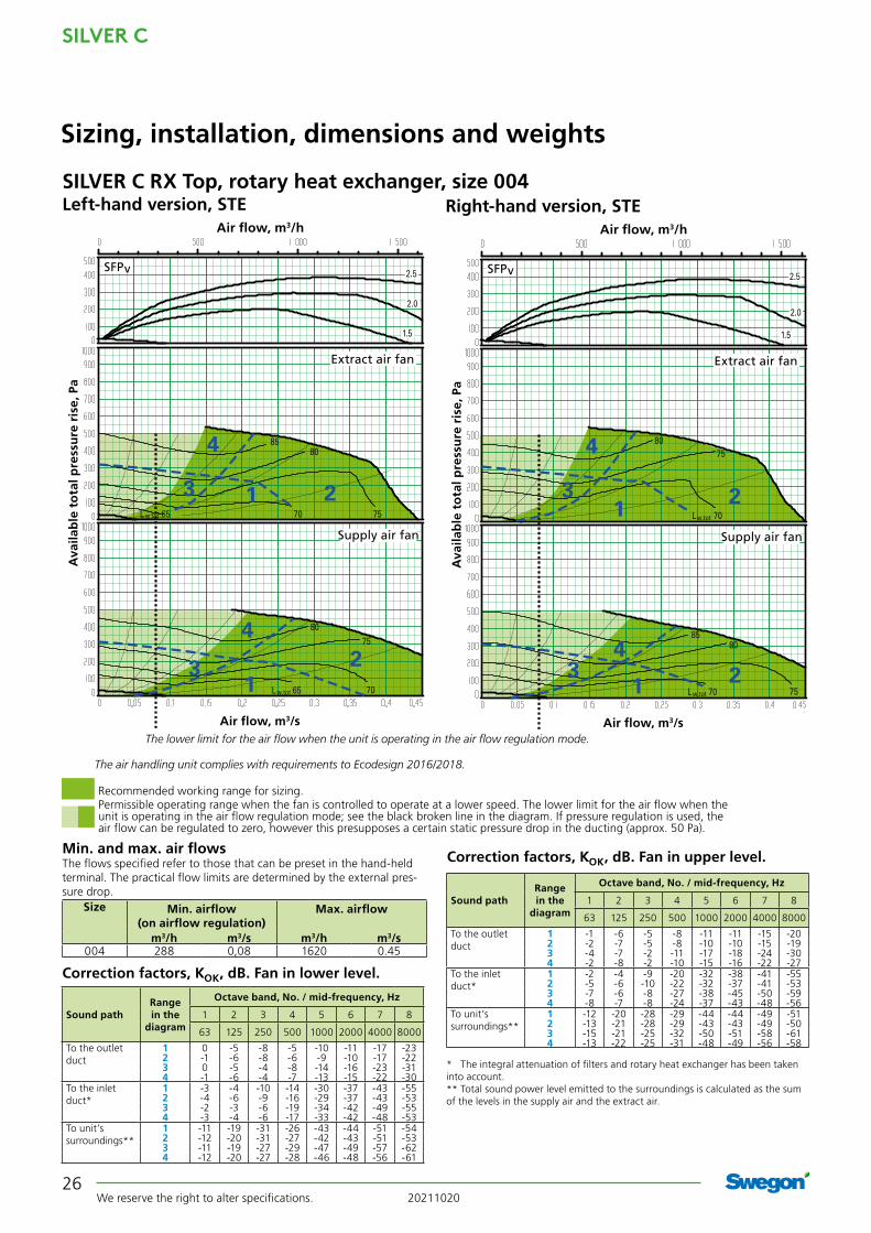
SILVER C RX Top, rotary heat exchanger, size 004
Min. and max. air flowsThe flows specified refer to those that can be preset in the hand-held terminal. The practical flow limits are determined by the external pres-sure drop.
* The integral attenuation of filters and rotary heat exchanger has been taken into account.** Total sound power level emitted to the surroundings is calculated as the sum of the levels in the supply air and the extract air.
Correction factors, KOK, dB. Fan in upper level.
Size Min. airflow (on airflow regulation)
Max. airflow
m3/h m3/s m3/h m3/s004 288 0,08 1620 0.45
Left-hand version, STE
Supply air fan
Extract air fan
SFPv
Air flow, m3/s
Ava
ilab
le t
ota
l pre
ssu
re r
ise,
Pa
Air flow, m3/h
Right-hand version, STE
Supply air fan
Extract air fan
SFPv
Air flow, m3/s
Ava
ilab
le t
ota
l pre
ssu
re r
ise,
Pa
Air flow, m3/h
Range in the
diagram
Octave band, No. / mid-frequency, Hz
Sound path 1 2 3 4 5 6 7 8
63 125 250 500 1000 2000 4000 8000
To the outletduct
1 -1 -6 -5 -8 -11 -11 -15 -202 -2 -7 -5 -8 -10 -10 -15 -193 -4 -7 -2 -11 -17 -18 -24 -304 -2 -8 -2 -10 -15 -16 -22 -27
To the inletduct*
1 -2 -4 -9 -20 -32 -38 -41 -552 -5 -6 -10 -22 -32 -37 -41 -533 -7 -6 -8 -27 -38 -45 -50 -594 -8 -7 -8 -24 -37 -43 -48 -56
To unit’s surroundings**
1 -12 -20 -28 -29 -44 -44 -49 -512 -13 -21 -28 -29 -43 -43 -49 -503 -15 -21 -25 -32 -50 -51 -58 -614 -13 -22 -25 -31 -48 -49 -56 -58
Range in the
diagram
Octave band, No. / mid-frequency, Hz
Sound path 1 2 3 4 5 6 7 8
63 125 250 500 1000 2000 4000 8000
To the outletduct
1 0 -5 -8 -5 -10 -11 -17 -232 -1 -6 -8 -6 -9 -10 -17 -223 0 -5 -4 -8 -14 -16 -23 -314 -1 -6 -4 -7 -13 -15 -22 -30
To the inletduct*
1 -3 -4 -10 -14 -30 -37 -43 -552 -4 -6 -9 -16 -29 -37 -43 -533 -2 -3 -6 -19 -34 -42 -49 -554 -3 -4 -6 -17 -33 -42 -48 -53
To unit’s surroundings**
1 -11 -19 -31 -26 -43 -44 -51 -542 -12 -20 -31 -27 -42 -43 -51 -533 -11 -19 -27 -29 -47 -49 -57 -624 -12 -20 -27 -28 -46 -48 -56 -61
Correction factors, KOK, dB. Fan in lower level.
Sizing, installation, dimensions and weights
The lower limit for the air flow when the unit is operating in the air flow regulation mode.
Recommended working range for sizing.Permissible operating range when the fan is controlled to operate at a lower speed. The lower limit for the air flow when the unit is operating in the air flow regulation mode; see the black broken line in the diagram. If pressure regulation is used, the air flow can be regulated to zero, however this presupposes a certain static pressure drop in the ducting (approx. 50 Pa).
The air handling unit complies with requirements to Ecodesign 2016/2018.

20211020 We reserve the right to alter specifications.
SILVER C
27
Size A B C D F H J L Ø Weight, kg
004 800 825 238 393 237 1085 579 1600 315 295-302
45 45J102102
76
3805214
D
C
D
C
F
F
SILVER C RX Top, rotary heat exchanger, size 004
Sizing, installation, dimensions and weights
Clear space for inspectionA clear space of 800 mm should be provided in front of the unit and at least 200 mm should be provided above the junction hood.
Delivery and transport within the siteThe SILVER C RX Top 004 unit is produced in one variant in which all the components are arranged at their given physical location inside the unit.
The unit can also be delivered as L-concept with top fed duct connections in combination with side fed duct connections, see the section Description Air handling unit.
The air handling unit is supplied on a wooden pallet.
Prefitted base beams are obtainable as optional equipment.
Installation/duct connection optionsA: All the duct connections are arranged from the top of the air handling unit (the unit must not be installed outdoors).
B: Specify right-hand or left-hand version when ordering.
Left-hand version Right-hand version
Electrical connection
Base beams are optional.
Outdoor air Supply air Extract air Exhaust air
Rated data per fanMotor shaft power: 0.8 kW (0.41 kW)*, motor control system: 1 x 230 V, 50 Hz, rated 2.3 A *The motor control system limits the power of the take-off to the value specified.
Motor, heat exchanger55 W, 1 x 230 V, 50 Hz, max. perm. fuse protection: 10A

SILVER C
We reserve the right to alter specifications. 2021102028
Min. and max. airflowsThe flows specified refer to those that can be preset in the hand-held micro terminal. The practical flow limits are deter-mined by the external pressure drop.
Correction factors, KOK , dB
Sizing, installation, dimensions and weights
Size Min. flow (For units operating in the airflow reg. mode)
Max. airflow
m3/h m3/s m3/h m3/s005 288 0,08 2340 0,65
* The integral attenuation of filters and rotary heat exchanger has been taken into account.** Total sound power level emitted to the surroundings is calculated as the sum of the levels
in the supply air and the extract air.
Rangein
diagram
Octave band, no./mid-frequency, Hz
Sound path 1 2 3 4 5 6 7 8
63 125 250 500 1000 2000 4000 8000
To the outletduct
1 -1 -6 -6 -8 -7 -7 -12 -152 -1 -5 -8 -8 -7 -9 -13 -163 -1 -2 -6 -15 -14 -16 -22 -254 -2 -3 -5 -13 -13 -14 -20 -25
To the inletduct*
1 -6 -9 -12 -22 -31 -33 -38 -372 -7 -10 -17 -18 -29 -31 -37 -383 -6 -4 -14 -27 -35 -39 -44 -434 -7 -5 -12 -22 -34 -36 -42 -43
To unit’s surroundings**
1 -12 -20 -29 -29 -40 -40 -46 -462 -12 -19 -31 -29 -40 -42 -47 -473 -12 -16 -29 -36 -47 -49 -56 -564 -13 -17 -28 -34 -46 -47 -54 -56
Recommended working range for sizing.Permissible operating range when the fan is controlled to operate at a lower speed. The lower limit for the airflow when the unit is operating in the airflow regulation mode; see the black broken line in the diagram. If pressure regulation is used, the airflow can be regulated to zero, however this presupposes a certain static pressure drop in the ducting (approx. 50 Pa).
Limit line, Ecodesign, 2016 Limit line, Ecodesign, 2018
2.5
2.01.5
1
2
4
1
23
4
70dB 75 80
85
Lw,tot
90
70dB 75 80
85
Lw,tot
9095
3
Supply air fan
Extract air fan
SFPv
Air flow, m3/s
Ava
ilab
le t
ota
l pre
ssu
re r
ise,
Pa
Air flow, m3/h
The lower limit for the air flow when the unit is operating in the air flow regulation mode.
Cap. var. 1
Cap. var. 2
Cap. var. 1
Cap. var. 2
The limit lines for Ecodesign are calculated with capacity variant 2. The mean value for supply air and extract air must be within the limit line.
SILVER C RX, rotary heat exchanger, size 005, common casingSTE

20211020 We reserve the right to alter specifications.
SILVER C
29
380
76 76
45 45J
14 = =ø 400 ø 315
52
284 284
Rated data per fanMotor shaft power: 0.8 kW alt. 1.15 kW, motor control system: 1 x 230 V, 50 Hz, rated 4.3 A alt. 5.5 A
Motor, heat exchanger55 W, 1 x 230 V, 50 Hz, max. perm. fuse protection: 10A
Clear space for inspectionA clear space of 800 mm should be provided in front of the unit and at least 200 mm should be provided above the junction hood.
Right-hand version
Left-hand version
Delivery and transport within the siteThe SILVER C RX 005 is produced in one single variant. All of its components are arranged at their given physical locations inside the air handling unit. The air handling unit is supplied on a wooden pallet.
Prefitted base beams are obtainable as optional equipment; a stand supplied unmounted is available as an accessory.
Duct connection optionsA: Specify right-hand or left-hand version when ordering.
B: The air handling unit can be installed up ended (Does not apply to units installed outdoors).
C: Specify upper fan outlet for upward air discharge when plac-ing orders (Does not apply to units installed outdoors). N.B.! Duct connection size: ø 400 mm.
D: Specify whether the unit shall have an air intake from above for outdoor air or extract air when placing orders (Does not apply to units installed outdoors).
Outdoor air Supply air Extract air Exhaust air
Sizing, installation, dimensions and weights
The base beams are optional equipment. * The air handling unit can be supplied without end connection panels. The AHU can also be supplied with full face end connection panel (accessory).
Size A B C D F G H J L Ø Weight, kg
005 743 825 240 345 230 460 920 579 1499 315 234-278
Cable entry
SILVER C RX, rotary heat exchanger, size 005, common casing

SILVER C
We reserve the right to alter specifications. 2021102030
SILVER C RX, rotary heat exchanger, size 005, split version
Min. and max. airflowsThe flows specified refer to those that can be preset in the hand-held micro terminal. The practical flow limits are deter-mined by the external pressure drop.
Correction factors, KOK , dB
Sizing, installation, dimensions and weights
Size Min. flow (For units operating in the airflow reg. mode)
Max. airflow
m3/h m3/s m3/h m3/s005 288 0,08 2340 0,65
* The integral attenuation of filters and rotary heat exchanger has been taken into account.** Total sound power level emitted to the surroundings is calculated as the sum of the levels
in the supply air and the extract air.
Rangein
diagram
Octave band, no./mid-frequency, Hz
Sound path 1 2 3 4 5 6 7 8
63 125 250 500 1000 2000 4000 8000
To the outletduct
1 -1 -6 -6 -8 -7 -7 -12 -152 -1 -5 -8 -8 -7 -9 -13 -163 -1 -2 -6 -15 -14 -16 -22 -254 -2 -3 -5 -13 -13 -14 -20 -25
To the inletduct*
1 -6 -9 -12 -22 -31 -33 -38 -372 -7 -10 -17 -18 -29 -31 -37 -383 -6 -4 -14 -27 -35 -39 -44 -434 -7 -5 -12 -22 -34 -36 -42 -43
To unit’s surroundings**
1 -12 -20 -29 -29 -40 -40 -46 -462 -12 -19 -31 -29 -40 -42 -47 -473 -12 -16 -29 -36 -47 -49 -56 -564 -13 -17 -28 -34 -46 -47 -54 -56
Recommended working range for sizing.Permissible operating range when the fan is controlled to operate at a lower speed. The lower limit for the airflow when the unit is operating in the airflow regulation mode; see the black broken line in the diagram. If pressure regulation is used, the airflow can be regulated to zero, however this presupposes a certain static pressure drop in the ducting (approx. 50 Pa).
Limit line, Ecodesign, 2016 Limit line, Ecodesign, 2018
2.5
2.01.5
1
2
4
1
23
4
70dB 75 80
85
Lw,tot
90
70dB 75 80
85
Lw,tot
9095
3
Supply air fan
Extract air fan
SFPv
Air flow, m3/s
Ava
ilab
le t
ota
l pre
ssu
re r
ise,
Pa
Air flow, m3/h
The lower limit for the air flow when the unit is operating in the air flow regulation mode.
Cap. var. 1
Cap. var. 2
Cap. var. 1
Cap. var. 2
The limit lines for Ecodesign are calculated with capacity variant 2. The mean value for supply air and extract air must be within the limit line.
STE

20211020 We reserve the right to alter specifications.
SILVER C
31
380 7676 14
45 45J
K
5252
ø 400 ø 315
284 284 45 45J
K
= =
SILVER C RX, rotary heat exchanger, size 005, split version
Sizing, installation, dimensions and weights
Delivery and transport within the siteThe SILVER C RX 005 can be supplied as one single unit, or in a number of different combinations of unit sections from the factory, see the section: Description of the Air Handling Unit/Delivery Configuration RX/PX/CX, sizes 004-080.
The unit sections are jointed together/split by means of bolts.
Prefitted base beams as standard.
Duct connection optionsA: Specify right-hand or left-hand version when ordering.
B: The arrangement of the functional sections can be vertically reversed. To be specified when placing an order, see the illustra-tion to the right.
C: Specify upper fan outlet for upward air discharge when plac-ing orders (Does not apply to units installed outdoors). N.B.! Duct connection size: ø 400 mm.
D: Specify whether the unit shall have an air intake from above for outdoor air or extract air when placing orders (Does not apply to units installed outdoors).
Size A B C D F G H J K L Ø Weight, kg
005 617 825 240 565 230 460 920 579 345 1799 315 278-335
The unit can be divided into three sections at the building site.Dimensions: See A and D in the table above.Weight: A = 88-112 kg, D = 102-111 kg.
Division into sections for transport
Right-hand version
Left-hand version
Outdoor air Supply air Extract air Exhaust air
Cable entry
The illustration shows the connections for supply air fan, right-hand/lower level and left-hand/upper level. For supply air fan, right-hand/upper level and left-hand/lower level, the connections are mirror-inverted.* The air handling unit is supplied without end connection panel if a duct accessory housed in an insulated casing will be connected. The AHU can also be supplied with full face end connection panel (accessory).
Clear space for inspectionA clear space of 800 mm should be provided in front of the unit and at least 200 mm should be provided above the junction hood.
Rated data per fanMotor shaft power: 0.8 kW alt. 1.15 kW, motor control system: 1 x 230 V, 50 Hz, rated 4.3 A alt. 5.5 A
Motor, heat exchanger55 W, 1 x 230 V, 50 Hz, max. perm. fuse protection: 10A
Supply air fan, right, lower level
Supply air fan, right, upper level
Supply air fan, left, upper level
Supply air fan, left, lower level
A AD

SILVER C
We reserve the right to alter specifications. 2021102032
1
23
4
Lw,tot 65
Lw,tot 65 70 75 80 85
2.52.01.5
12
3
4
70 75
85
90
80
123
4
Lw,tot 70
Lw,tot 70 75 80
80
2.52.01.5
12
3
4
75 80
85
85
90
SILVER C RX Top, rotary heat exchanger, size 005
Sizing, installation, dimensions and weights
Left-hand version, STE
Supply air fan
Extract air fan
SFPv
Air flow, m3/s
Ava
ilab
le t
ota
l pre
ssu
re r
ise,
Pa
Air flow, m3/h
Right-hand version, STE
Supply air fan
SFPv
Air flow, m3/s
Ava
ilab
le t
ota
l pre
ssu
re r
ise,
Pa
Air flow, m3/h
Min. and max. air flowsThe flows specified refer to those that can be preset in the hand-held terminal. The practical flow limits are determined by the external pres-sure drop.
* The integral attenuation of filters and rotary heat exchanger has been taken into account.** Total sound power level emitted to the surroundings is calculated as the sum of the levels in the supply air and the extract air.
Size Min. airflow (on airflow regulation)
Max. airflow
m3/h m3/s m3/h m3/s005 288 0,08 2340 0,65
Range in the
diagram
Octave band, No. / mid-frequency, Hz
Sound path 1 2 3 4 5 6 7 8
63 125 250 500 1000 2000 4000 8000
To the outletduct
1 -1 -6 -5 -8 -11 -11 -15 -202 -2 -7 -5 -8 -10 -10 -15 -193 -4 -7 -2 -11 -17 -18 -24 -304 -2 -8 -2 -10 -15 -16 -22 -27
To the inletduct*
1 -2 -4 -9 -20 -32 -38 -41 -552 -5 -6 -10 -22 -32 -37 -41 -533 -7 -6 -8 -27 -38 -45 -50 -594 -8 -7 -8 -24 -37 -43 -48 -56
To unit’s surroundings**
1 -12 -20 -28 -29 -44 -44 -49 -512 -13 -21 -28 -29 -43 -43 -49 -503 -15 -21 -25 -32 -50 -51 -58 -614 -13 -22 -25 -31 -48 -49 -56 -58
Range in the
diagram
Octave band, No. / mid-frequency, Hz
Sound path 1 2 3 4 5 6 7 8
63 125 250 500 1000 2000 4000 8000
To the outletduct
1 0 -5 -8 -5 -10 -11 -17 -232 -1 -6 -8 -6 -9 -10 -17 -223 0 -5 -4 -8 -14 -16 -23 -314 -1 -6 -4 -7 -13 -15 -22 -30
To the inletduct*
1 -3 -4 -10 -14 -30 -37 -43 -552 -4 -6 -9 -16 -29 -37 -43 -533 -2 -3 -6 -19 -34 -42 -49 -554 -3 -4 -6 -17 -33 -42 -48 -53
To unit’s surroundings**
1 -11 -19 -31 -26 -43 -44 -51 -542 -12 -20 -31 -27 -42 -43 -51 -533 -11 -19 -27 -29 -47 -49 -57 -624 -12 -20 -27 -28 -46 -48 -56 -61
Correction factors, KOK, dB. Fan in upper level.
Correction factors, KOK, dB. Fan in lower level.
For Ecodesign, the mean value for supply air and extract air must be within the limit line.
Cap. var. 1
Cap. var. 1
Cap. var. 2
Cap. var. 1
Cap. var. 2
Cap. var. 1
Cap. var. 2
Recommended working range for sizing.Permissible operating range when the fan is controlled to operate at a lower speed. The lower limit for the airflow when the unit is operating in the airflow regulation mode; see the black broken line in the diagram. If pressure regulation is used, the airflow can be regulated to zero, however this presupposes a certain static pressure drop in the ducting (approx. 50 Pa).
Limit line, Ecodesign, 2018
The lower limit for the air flow when the unit is operating in the air flow regulation mode.

20211020 We reserve the right to alter specifications.
SILVER C
33
Size A B C D F H J L Ø Weight, kg
005 800 825 238 393 237 1085 579 1600 315 295-310
45 45J102102
76
3805214
D
C
D
C
F
F
SILVER C RX Top, rotary heat exchanger, size 005
Sizing, installation, dimensions and weights
Clear space for inspectionA clear space of 800 mm should be provided in front of the unit and at least 200 mm should be provided above the junction hood.
Delivery and transport within the siteThe SILVER C RX Top 005 unit is produced in one variant in which all the components are arranged at their given physical location inside the unit.
The unit can also be delivered as L-concept with top fed duct connections in combination with side fed duct connections, see the section Description Air handling unit.
The air handling unit is supplied on a wooden pallet.
Prefitted base beams are obtainable as optional equipment.
Installation/duct connection optionsA: All the duct connections are arranged from the top of the air handling unit (the unit must not be installed outdoors).
B: Specify right-hand or left-hand version when ordering.
Left-hand version Right-hand version
Electrical connection
Base beams are optional.
Rated data per fanMotor shaft power: 0.8 kW alt. 1.15 kW, motor control system: 1 x 230 V, 50 Hz, rated 4.3 A alt. 5.5 A
Motor, heat exchanger55 W, 1 x 230 V, 50 Hz, max. perm. fuse protection: 10A
Outdoor air Supply air Extract air Exhaust air
SILVER C
We reserve the right to alter specifications. 2021102034
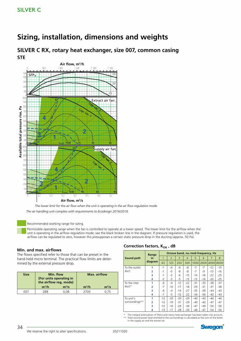
Min. and max. airflowsThe flows specified refer to those that can be preset in the hand-held micro terminal. The practical flow limits are deter-mined by the external pressure drop.
Correction factors, KOK , dB
Sizing, installation, dimensions and weights
Size Min. flow (For units operating in the airflow reg. mode)
Max. airflow
m3/h m3/s m3/h m3/s007 288 0,08 2700 0,75
* The integral attenuation of filters and rotary heat exchanger has been taken into account.** Total sound power level emitted to the surroundings is calculated as the sum of the levels
in the supply air and the extract air.
Rangein
diagram
Octave band, no./mid-frequency, Hz
Sound path 1 2 3 4 5 6 7 8
63 125 250 500 1000 2000 4000 8000
To the outletduct
1 -1 -6 -6 -8 -7 -7 -12 -152 -1 -5 -8 -8 -7 -9 -13 -163 -1 -2 -6 -15 -14 -16 -22 -254 -2 -3 -5 -13 -13 -14 -20 -25
To the inletduct*
1 -6 -9 -12 -22 -31 -33 -38 -372 -7 -10 -17 -18 -29 -31 -37 -383 -6 -4 -14 -27 -35 -39 -44 -434 -7 -5 -12 -22 -34 -36 -42 -43
To unit’s surroundings**
1 -12 -20 -29 -29 -40 -40 -46 -462 -12 -19 -31 -29 -40 -42 -47 -473 -12 -16 -29 -36 -47 -49 -56 -564 -13 -17 -28 -34 -46 -47 -54 -56
Recommended working range for sizing.
Permissible operating range when the fan is controlled to operate at a lower speed. The lower limit for the airflow when the unit is operating in the airflow regulation mode; see the black broken line in the diagram. If pressure regulation is used, the airflow can be regulated to zero, however this presupposes a certain static pressure drop in the ducting (approx. 50 Pa).
2.5
2.0
1.5
123
4
123
4
70dB 75 80 85Lw,tot
90
70dB 75 80 85Lw,tot
90 Supply air fan
Extract air fan
SFPv
Air flow, m3/s
Ava
ilab
le t
ota
l pre
ssu
re r
ise,
Pa
Air flow, m3/h
The lower limit for the air flow when the unit is operating in the air flow regulation mode.
Cap. var. 1
Cap. var. 2
Cap. var. 1
Cap. var. 2
The air handling unit complies with requirements to Ecodesign 2016/2018.
SILVER C RX, rotary heat exchanger, size 007, common casingSTE

20211020 We reserve the right to alter specifications.
SILVER C
35
380
76 76
45 45J
16 = =
52
305 305
ø 500 ø 400
Sizing, installation, dimensions and weights
Rated data per fanMotor shaft power: 0.8 kW alt. 1.15 kW, motor control system: 1 x 230 V, 50 Hz, rated 4.3 A alt. 5.5 A
Motor, heat exchanger55 W, 1 x 230 V, 50 Hz, max. perm. fuse protection: 10A
Clear space for inspectionA clear space of 900 mm should be provided in front of the unit and at least 200 mm should be provided above the junction hood.
Right-hand version
Left-hand version
Delivery and transport within the siteThe SILVER C RX 007 is produced in one single variant. All of its components are arranged at their given physical locations inside the air handling unit. The air handling unit is supplied on a wooden pallet.
Prefitted base beams are obtainable as optional equipment; a stand supplied unmounted is available as an accessory.
Duct connection optionsA: Specify right-hand or left-hand version when ordering.
B: The air handling unit can be installed up ended (Does not apply to units installed outdoors).
C: Specify upper fan outlet for upward air discharge when plac-ing orders (Does not apply to units installed outdoors). N.B.! Duct connection size: ø 500 mm.
D: Specify whether the unit shall have an air intake from above for outdoor air or extract air when placing orders (Does not apply to units installed outdoors).
Outdoor air Supply air Extract air Exhaust air
The base beams are optional equipment. * The air handling unit can be supplied without end connection panels. The AHU can also be supplied with full face end connection panel (accessory).
Size A B C D F G H J L Ø Weight, kg
007 805 995 277,5 440 271 543 1085 749 1619 400 281-355
Cable entry
SILVER C RX, rotary heat exchanger, size 007, common casing

SILVER C
We reserve the right to alter specifications. 2021102036
SILVER C RX, rotary heat exchanger, size 007, split version
Min. and max. airflowsThe flows specified refer to those that can be preset in the hand-held micro terminal. The practical flow limits are deter-mined by the external pressure drop.
Correction factors, KOK , dB
Sizing, installation, dimensions and weights
Size Min. flow (For units operating in the airflow reg. mode)
Max. airflow
m3/h m3/s m3/h m3/s007 288 0,08 2700 0,75
* The integral attenuation of filters and rotary heat exchanger has been taken into account.** Total sound power level emitted to the surroundings is calculated as the sum of the levels
in the supply air and the extract air.
Rangein
diagram
Octave band, no./mid-frequency, Hz
Sound path 1 2 3 4 5 6 7 8
63 125 250 500 1000 2000 4000 8000
To the outletduct
1 -1 -6 -6 -8 -7 -7 -12 -152 -1 -5 -8 -8 -7 -9 -13 -163 -1 -2 -6 -15 -14 -16 -22 -254 -2 -3 -5 -13 -13 -14 -20 -25
To the inletduct*
1 -6 -9 -12 -22 -31 -33 -38 -372 -7 -10 -17 -18 -29 -31 -37 -383 -6 -4 -14 -27 -35 -39 -44 -434 -7 -5 -12 -22 -34 -36 -42 -43
To unit’s surroundings**
1 -12 -20 -29 -29 -40 -40 -46 -462 -12 -19 -31 -29 -40 -42 -47 -473 -12 -16 -29 -36 -47 -49 -56 -564 -13 -17 -28 -34 -46 -47 -54 -56
Recommended working range for sizing.
Permissible operating range when the fan is controlled to operate at a lower speed. The lower limit for the airflow when the unit is operating in the airflow regulation mode; see the black broken line in the diagram. If pressure regulation is used, the airflow can be regulated to zero, however this presupposes a certain static pressure drop in the ducting (approx. 50 Pa).
2.5
2.0
1.5
123
4
123
4
70dB 75 80 85Lw,tot
90
70dB 75 80 85Lw,tot
90 Supply air fan
Extract air fan
SFPv
Air flow, m3/s
Ava
ilab
le t
ota
l pre
ssu
re r
ise,
Pa
Air flow, m3/h
The lower limit for the air flow when the unit is operating in the air flow regulation mode.
Cap. var. 1
Cap. var. 2
Cap. var. 1
Cap. var. 2
The air handling unit complies with requirements to Ecodesign 2016/2018.
STE

20211020 We reserve the right to alter specifications.
SILVER C
37
A AD
SILVER C RX, rotary heat exchanger, size 007, split versionDelivery and transport within the siteThe SILVER C RX 007 can be supplied as one single unit, or in a number of different combinations of unit sections from the factory, see the section: Description of the Air Handling Unit/Delivery Configuration RX/PX/CX, sizes 004-080.
The unit sections are jointed together/split by means of bolts.
Prefitted base beams as standard.
Duct connection optionsA: Specify right-hand or left-hand version when ordering.
B: The arrangement of the functional sections can be vertically reversed. To be specified when placing an order, see the illustra-tion to the right.
C: Specify upper fan outlet for upward air discharge when plac-ing orders (Does not apply to units installed outdoors). N.B.! Duct connection size: ø 500 mm.
D: Specify whether the unit shall have an air intake from above for outdoor air or extract air when placing orders (Does not apply to units installed outdoors).
Size A B C D F G H J K L Ø Weight, kg
007 647.5 995 277.5 565 271 543 1085 749 440 1860 400 327-412
The unit can be divided into three sections at the building site.Dimensions: See A and D in the table above.Weight: A = 103-138 kg, D = 121-136 kg.
Division into sections for transport
The illustration shows the connections for supply air fan, right-hand/lower level and left-hand/upper level. For supply air fan, right-hand/upper level and left-hand/lower level, the connections are mirror-inverted.* The air handling unit is supplied without end connection panel if a duct accessory housed in an insulated casing will be connected. The AHU can also be supplied with full face end connection panel (accessory).
Sizing, installation, dimensions and weights
Clear space for inspectionA clear space of 900 mm should be provided in front of the unit and at least 200 mm should be provided above the junction hood.
Rated data per fanMotor shaft power: 0.8 kW alt. 1.15 kW, motor control system: 1 x 230 V, 50 Hz, rated 4.3 A alt. 5.5 A
Motor, heat exchanger55 W, 1 x 230 V, 50 Hz, max. perm. fuse protection: 10A
Right-hand version
Left-hand version
Outdoor air Supply air Extract air Exhaust air
380
76 76
16
45 45J
K
= =
45 45J
K
5252
ø 500 ø 400
305 305
Cable entry
Supply air fan, right, lower level
Supply air fan, right, upper level
Supply air fan, left, upper level
Supply air fan, left, lower level

SILVER C
We reserve the right to alter specifications. 2021102038
123
4
Lw,tot 65
Lw,tot 65 70 75 80 85
2.5
2.01.5
123
4
70 75 80
90
8580
123
4
Lw,tot 70
Lw,tot 70 75 80
8085
2.5
2.01.5
123
4
75 80 85
90
Cap. var. 1
Cap. var. 2
Cap. var. 1
Cap. var. 2
Cap. var. 1
Cap. var. 2
Cap. var. 1
Cap. var. 2
SILVER C RX Top, rotary heat exchanger, size 007
Sizing, installation, dimensions and weights
Size Min. airflow (for airflow regulation)
Max. airflow
m3/h m3/s m3/h m3/s007 288 0,08 2700 0.75
Left-hand version, STE Right-hand version, STE
Supply air fan
Extract air fan
SFPv
Air flow, m3/s
Ava
ilab
le t
ota
l pre
ssu
re r
ise,
Pa
Air flow, m3/h
Supply air fan
Extract air fan
SFPv
Air flow, m3/s
Ava
ilab
le t
ota
l pre
ssu
re r
ise,
Pa
Air flow, m3/h
Min. and max. air flowsThe flows specified refer to those that can be preset in the hand-held terminal. The practical flow limits are determined by the external pres-sure drop.
* The integral attenuation of filters and rotary heat exchanger has been taken into account.** Total sound power level emitted to the surroundings is calculated as the sum of the levels in the supply air and the extract air.
Range in the
diagram
Octave band, no./mid-frequency, Hz
Sound path 1 2 3 4 5 6 7 8
63 125 250 500 1000 2000 4000 8000
To the outletduct
1 -3 -7 -9 -5 -11 -10 -15 -192 -2 -7 -9 -5 -10 -8 -13 -173 -1 -3 -4 -14 -18 -17 -25 -294 -1 -5 -3 -11 -15 -15 -22 -28
To the inletduct*
1 -6 -8 -18 -21 -32 -37 -40 -532 -7 -9 -16 -19 -33 -36 -39 -513 -4 -4 -13 -28 -40 -45 -50 -604 -6 -6 -10 -24 -37 -43 -47 -54
To unit’s surroundings**
1 -14 -21 -32 -26 -44 -43 -49 -502 -13 -21 -32 -26 -43 -41 -47 -483 -12 -17 -27 -35 -51 -50 -59 -604 -12 -19 -26 -32 -48 -48 -56 -59
Range in the
diagram
Octave band, no./mid-frequency, Hz
Sound path 1 2 3 4 5 6 7 8
63 125 250 500 1000 2000 4000 8000
To the outletduct
1 0 -8 -10 -3 -9 -9 -16 -222 -1 -8 -10 -5 -8 -7 -14 -193 1 -3 -5 -10 -15 -15 -23 -304 -1 -6 -4 -7 -13 -13 -20 -27
To the inletduct*
1 -3 -6 -17 -16 -30 -35 -40 -502 -4 -6 -15 -16 -29 -32 -38 -473 0 -1 -11 -21 -36 -39 -45 -514 -2 -2 -8 -17 -33 -36 -41 -46
To unit’s surroundings**
1 -11 -22 -33 -24 -42 -42 -50 -532 -12 -22 -33 -26 -41 -40 -48 -503 -10 -17 -28 -31 -48 -48 -57 -614 -12 -20 -27 -28 -46 -46 -54 -58
Correction factors, KOK, dB. Fan in upper level.
Correction factors, KOK, dB. Fan in lower level.
For Ecodesign, the mean value for supply air and extract air must be within the limit line. The lower limit for the air flow when the unit is operating in the air flow regulation mode.
Recommended working range for sizing.Permissible operating range when the fan is controlled to operate at a lower speed. The lower limit for the airflow when the unit is operating in the airflow regulation mode; see the black broken line in the diagram. If pressure regulation is used, the airflow can be regulated to zero, however this presupposes a certain static pressure drop in the ducting (approx. 50 Pa).Limit line, Ecodesign, 2018

20211020 We reserve the right to alter specifications.
SILVER C
39
45 45J102102
76
3805216
D
C
E
C
F
F
SILVER C RX Top, rotary heat exchanger, size 007
Sizing, installation, dimensions and weights
Size A B C D E F H J L Ø Weight, kg
007 860 995 286 426 406 280 1295 749 1720 400 351-376
Clear space for inspectionA clear space of 900 mm should be provided in front of the unit and at least 200 mm should be provided above the junction hood.
Delivery and transport within the siteThe SILVER C RX Top 007 unit is produced in one variant in which all the components are arranged at their given physical location inside the unit.
The unit can also be delivered as L-concept with top fed duct connections in combination with side fed duct connections, see the section Description Air handling unit.
The air handling unit is supplied on a wooden pallet.
Prefitted base beams are obtainable as optional equipment.
Installation/duct connection optionsA: All the duct connections are arranged from the top of the air handling unit (the unit must not be installed outdoors).
B: Specify right-hand or left-hand version when ordering.
Left-hand version Right-hand version
Electrical connection
Base beams are optional.
Rated data per fanMotor shaft power: 0.8 kW alt. 1.15 kW, motor control system: 1 x 230 V, 50 Hz, rated 4.3 A alt. 5.5 A
Motor, heat exchanger55 W, 1 x 230 V, 50 Hz, max. perm. fuse protection: 10A

SILVER C
We reserve the right to alter specifications. 2021102040
Min. and max. airflowsThe flows specified refer to those that can be preset in the hand-held micro terminal. The practical flow limits are deter-mined by the external pressure drop.
Correction factors, KOK , dB
Sizing, installation, dimensions and weights
Size Min. flow (For units operating in the airflow reg. mode)
Max. airflow
m3/h m3/s m3/h m3/s008 720 0,20 3600 1,00
* The integral attenuation of filters and rotary heat exchanger has been taken into account.** Total sound power level emitted to the surroundings is calculated as the sum of the levels
in the supply air and the extract air.
Rangein
diagram
Octave band, no./mid-frequency, Hz
Sound path 1 2 3 4 5 6 7 8
63 125 250 500 1000 2000 4000 8000
To the outletduct
1 -1 -6 -6 -8 -7 -7 -12 -152 -1 -5 -8 -8 -7 -9 -13 -163 -1 -2 -6 -15 -14 -16 -22 -254 -2 -3 -5 -13 -13 -14 -20 -25
To the inletduct*
1 -6 -9 -12 -22 -31 -33 -38 -372 -7 -10 -17 -18 -29 -31 -37 -383 -6 -4 -14 -27 -35 -39 -44 -434 -7 -5 -12 -22 -34 -36 -42 -43
To unit’s surroundings**
1 -12 -20 -29 -29 -40 -40 -46 -462 -12 -19 -31 -29 -40 -42 -47 -473 -12 -16 -29 -36 -47 -49 -56 -564 -13 -17 -28 -34 -46 -47 -54 -56
Recommended working range for sizing.Permissible operating range when the fan is controlled to operate at a lower speed. The lower limit for the airflow when the unit is operating in the airflow regulation mode; see the black broken line in the diagram. If pressure regulation is used, the airflow can be regulated to zero, however this presupposes a certain static pressure drop in the ducting (approx. 50 Pa).
Limit line, Ecodesign, 2018
2.5
2.01.5
70dB 75 80 85
90
Lw,tot
70dB 75 80 85
90
Lw,tot
1
23
4
1
23
4
Supply air fan
Extract air fan
SFPv
Air flow, m3/s
Ava
ilab
le t
ota
l pre
ssu
re r
ise,
Pa
The lower limit for the air flow when the unit is operating in the air flow regulation mode.
Cap. var. 1
Cap. var. 2
Cap. var. 1
Cap. var. 2
The limit line for Ecodesign 2018 is calculated with capacity variant 2. The mean value for supply air and extract air must be within the limit line. The air handling unit complies with requirements to Ecodesign 2016.
SILVER C RX, rotary heat exchanger, size 008, common casingSTE

20211020 We reserve the right to alter specifications.
SILVER C
41
380
76 76
45 45J
16 = =
52
305 305
ø 500 ø 400
Sizing, installation, dimensions and weights
Rated data per fanCapacity variant 1: Motor shaft power: 1.15 kW, motor control system: 1 x 230 V, 50 Hz, rated 6.0 A
Capacity variant 2: Motor shaft power 1.6 kW, motor control system: 3 x 400 V, 50 Hz, rated 2.8 A
Motor, heat exchanger55 W, 1 x 230 V, 50 Hz, max. perm. fuse protection: 10A
Clear space for inspectionA clear space of 900 mm should be provided in front of the unit and at least 200 mm should be provided above the junction hood.
Right-hand version
Left-hand version
Delivery and transport within the siteThe SILVER C RX 008 is produced in one single variant. All of its components are arranged at their given physical locations inside the air handling unit. The air handling unit is supplied on a wooden pallet.
Prefitted base beams are obtainable as optional equipment; a stand supplied unmounted is available as an accessory.
Duct connection optionsA: Specify right-hand or left-hand version when ordering.
B: The air handling unit can be installed up ended (Does not apply to units installed outdoors).
C: Specify upper fan outlet for upward air discharge when plac-ing orders (Does not apply to units installed outdoors). N.B.! Duct connection size: ø 500 mm.
D: Specify whether the unit shall have an air intake from above for outdoor air or extract air when placing orders (Does not apply to units installed outdoors).
Outdoor air Supply air Extract air Exhaust air
The base beams are optional equipment. * The air handling unit can be supplied without end connection panels. The AHU can also be supplied with full face end connection panel (accessory).
Size A B C D F G H J L Ø Weight, kg
008 805 995 277,5 440 271 543 1085 749 1619 400 295-363
Cable entry
SILVER C RX, rotary heat exchanger, size 008, common casing

SILVER C
We reserve the right to alter specifications. 2021102042
SILVER C RX, rotary heat exchanger, size 008, split version
Min. and max. airflowsThe flows specified refer to those that can be preset in the hand-held micro terminal. The practical flow limits are deter-mined by the external pressure drop.
Correction factors, KOK , dB
Sizing, installation, dimensions and weights
Size Min. flow (For units operating in the airflow reg. mode)
Max. airflow
m3/h m3/s m3/h m3/s008 720 0,20 3600 1,00
* The integral attenuation of filters and rotary heat exchanger has been taken into account.** Total sound power level emitted to the surroundings is calculated as the sum of the levels
in the supply air and the extract air.
Rangein
diagram
Octave band, no./mid-frequency, Hz
Sound path 1 2 3 4 5 6 7 8
63 125 250 500 1000 2000 4000 8000
To the outletduct
1 -1 -6 -6 -8 -7 -7 -12 -152 -1 -5 -8 -8 -7 -9 -13 -163 -1 -2 -6 -15 -14 -16 -22 -254 -2 -3 -5 -13 -13 -14 -20 -25
To the inletduct*
1 -6 -9 -12 -22 -31 -33 -38 -372 -7 -10 -17 -18 -29 -31 -37 -383 -6 -4 -14 -27 -35 -39 -44 -434 -7 -5 -12 -22 -34 -36 -42 -43
To unit’s surroundings**
1 -12 -20 -29 -29 -40 -40 -46 -462 -12 -19 -31 -29 -40 -42 -47 -473 -12 -16 -29 -36 -47 -49 -56 -564 -13 -17 -28 -34 -46 -47 -54 -56
Recommended working range for sizing.Permissible operating range when the fan is controlled to operate at a lower speed. The lower limit for the airflow when the unit is operating in the airflow regulation mode; see the black broken line in the diagram. If pressure regulation is used, the airflow can be regulated to zero, however this presupposes a certain static pressure drop in the ducting (approx. 50 Pa).
Limit line, Ecodesign, 2018
2.5
2.01.5
70dB 75 80 85
90
Lw,tot
70dB 75 80 85
90
Lw,tot
1
23
4
1
23
4
Supply air fan
Extract air fan
SFPv
Air flow, m3/s
Ava
ilab
le t
ota
l pre
ssu
re r
ise,
Pa
The lower limit for the air flow when the unit is operating in the air flow regulation mode.
Cap. var. 1
Cap. var. 2
Cap. var. 1
Cap. var. 2
The limit line for Ecodesign 2018 is calculated with capacity variant 2. The mean value for supply air and extract air must be within the limit line. The air handling unit complies with requirements to Ecodesign 2016.
STE

20211020 We reserve the right to alter specifications.
SILVER C
43
SILVER C RX, rotary heat exchanger, size 008, split versionDelivery and transport within the siteThe SILVER C RX 008 can be supplied as one single unit, or in a number of different combinations of unit sections from the factory, see the section: Description of the Air Handling Unit/Delivery Configuration RX/PX/CX, sizes 004-080.
The unit sections are jointed together/split by means of bolts.
Prefitted base beams as standard.
Duct connection optionsA: Specify right-hand or left-hand version when ordering.
B: The arrangement of the functional sections can be vertically reversed. To be specified when placing an order, see the illustra-tion to the right.
C: Specify upper fan outlet for upward air discharge when plac-ing orders (Does not apply to units installed outdoors). N.B.! Duct connection size: ø 500 mm.
D: Specify whether the unit shall have an air intake from above for outdoor air or extract air when placing orders (Does not apply to units installed outdoors).
Size A B C D F G H J K L Ø Weight, kg
008 647.5 995 277.5 565 271 543 1085 749 440 1860 400 341-420
The unit can be divided into three sections at the building site.Dimensions: See A and D in the table above.Weight: A = 110-142 kg, D = 121-136 kg.
Division into sections for transport
Clear space for inspectionA clear space of 900 mm should be provided in front of the unit and at least 200 mm should be provided above the junction hood.
Sizing, installation, dimensions and weights
Right-hand version
Left-hand version
Outdoor air Supply air Extract air Exhaust air
The illustration shows the connections for supply air fan, right-hand/lower level and left-hand/upper level. For supply air fan, right-hand/upper level and left-hand/lower level, the connections are mirror-inverted.* The air handling unit is supplied without end connection panel if a duct accessory housed in an insulated casing will be connected. The AHU can also be supplied with full face end connection panel (accessory).
380
76 76
16
45 45J
K
= =
45 45J
K
5252
ø 500 ø 400
305 305
Cable entry
Rated data per fanCapacity variant 1: Motor shaft power: 1.15 kW, motor control system: 1 x 230 V, 50 Hz, rated 6.0 A
Capacity variant 2: Motor shaft power 1.6 kW, motor control system: 3 x 400 V, 50 Hz, rated 2.8 A
Motor, heat exchanger55 W, 1 x 230 V, 50 Hz, max. perm. fuse protection: 10A
Supply air fan, right, lower level
Supply air fan, right, upper level
Supply air fan, left, upper level
Supply air fan, left, lower level
A AD

SILVER C
We reserve the right to alter specifications. 2021102044
123
4
Lw,tot 65
Lw,tot 70 75 80 85 90
2.52.01.5
123
4
70 75 80
95
85
123
4
Lw,tot 70
Lw,tot 70 75 80 85
2.52.01.5
1 23
4
75 80 85
90
95
Cap. var. 1
Cap. var. 2
Cap. var. 1
Cap. var. 2
Cap. var. 1
Cap. var. 2
Cap. var. 1
Cap. var. 2
SILVER C RX Top, rotary heat exchanger, size 008
Sizing, installation, dimensions and weights
Left-hand version, STE
Supply air fan
Extract air fan
SFPv
Air flow, m3/s
Ava
ilab
le t
ota
l pre
ssu
re r
ise,
Pa
Air flow, m3/h
Right-hand version, STE
Supply air fan
Extract air fan
SFPv
Air flow, m3/s
Ava
ilab
le t
ota
l pre
ssu
re r
ise,
Pa
Air flow, m3/h
Size Min. airflow (on airflow regulation)
Max. airflow
m3/h m3/s m3/h m3/s008 720 0,20 3600 1.00
Min. and max. air flowsThe flows specified refer to those that can be preset in the hand-held terminal. The practical flow limits are determined by the external pres-sure drop.
* The integral attenuation of filters and rotary heat exchanger has been taken into account.** Total sound power level emitted to the surroundings is calculated as the sum of the levels in the supply air and the extract air.
Range in the
diagram
Octave band, No. / mid-frequency, Hz
Sound path 1 2 3 4 5 6 7 8
63 125 250 500 1000 2000 4000 8000
To the outletduct
1 -2 -6 -3 -13 -14 -14 -21 -272 -3 -6 -7 -6 -10 -11 -17 -213 -1 -3 -4 -17 -19 -19 -29 -364 -2 -4 -3 -13 -16 -17 -25 -31
To the inletduct*
1 -4 -4 -11 -26 -37 -40 -45 -582 -6 -8 -15 -18 -33 -37 -42 -533 -4 -5 -12 -30 -42 -46 -53 -624 -6 -6 -11 -26 -39 -44 -50 -57
To unit’s surroundings**
1 -13 -20 -26 -34 -47 -47 -55 -582 -14 -20 -30 -27 -43 -44 -51 -523 -12 -17 -27 -38 -52 -52 -63 -674 -13 -18 -26 -34 -49 -50 -59 -62
Range in the
diagram
Octave band, No. / mid-frequency, Hz
Sound path 1 2 3 4 5 6 7 8
63 125 250 500 1000 2000 4000 8000
To the outletduct
1 1 -6 -5 -8 -11 -11 -18 -262 0 -6 -8 -5 -8 -10 -16 -223 2 -3 -5 -12 -16 -17 -26 -344 0 -5 -4 -9 -14 -15 -24 -31
To the inletduct*
1 2 -1 -10 -19 -32 -36 -43 -542 -2 -6 -14 -15 -29 -35 -41 -513 1 -1 -11 -22 -37 -43 -50 -574 -3 -3 -9 -19 -35 -41 -47 -52
To unit’s surroundings**
1 -10 -20 -28 -29 -44 -44 -52 -572 -11 -20 -31 -26 -41 -43 -50 -533 -9 -17 -28 -33 -49 -50 -60 -654 -11 -19 -27 -30 -47 -48 -58 -62
Correction factors, KOK, dB. Fan in upper level.
Correction factors, KOK, dB. Fan in lower level.
For Ecodesign, the mean value for supply air and extract air must be within the limit line. The lower limit for the air flow when the unit is operating in the air flow regulation mode.
Recommended working range for sizing.Permissible operating range when the fan is controlled to operate at a lower speed. The lower limit for the airflow when the unit is operating in the airflow regulation mode; see the black broken line in the diagram. If pressure regulation is used, the airflow can be regulated to zero, however this presupposes a certain static pressure drop in the ducting (approx. 50 Pa).Limit line, Ecodesign, 2018

20211020 We reserve the right to alter specifications.
SILVER C
45
45 45J102102
76
380 185216
D
C
E
C
F
F
SILVER C RX Top, rotary heat exchanger, size 008
Sizing, installation, dimensions and weights
Size A B C D E F H J L Ø Weight, kg
008 860 995 286 426 406 280 1295 749 1720 400 369-382
Clear space for inspectionA clear space of 900 mm should be provided in front of the unit and at least 200 mm should be provided above the junction hood.
Delivery and transport within the siteThe SILVER C RX Top 008 unit is produced in one variant in which all the components are arranged at their given physical location inside the unit.
The unit can also be delivered as L-concept with top fed duct connections in combination with side fed duct connections, see the section Description Air handling unit.
The air handling unit is supplied on a wooden pallet.
Prefitted base beams are obtainable as optional equipment.
Installation/duct connection optionsA: All the duct connections are arranged from the top of the air handling unit (the unit must not be installed outdoors).
B: Specify right-hand or left-hand version when ordering.
Left-hand version Right-hand version
Electrical connection
Base beams are optional.
Outdoor air Supply air Extract air Exhaust air
Rated data per fanCapacity variant 1: Motor shaft power: 1.15 kW, motor control system: 1 x 230 V, 50 Hz, rated 6.0 A
Capacity variant 2: Motor shaft power 1.6 kW, motor control system: 3 x 400 V, 50 Hz, rated 2.8 A
Motor, heat exchanger55 W, 1 x 230 V, 50 Hz, max. perm. fuse protection: 10A

SILVER C
We reserve the right to alter specifications. 2021102046
Min. and max. airflowsThe flows specified refer to those that can be preset in the hand-held micro terminal. The practical flow limits are deter-mined by the external pressure drop.
Correction factors, KOK , dB
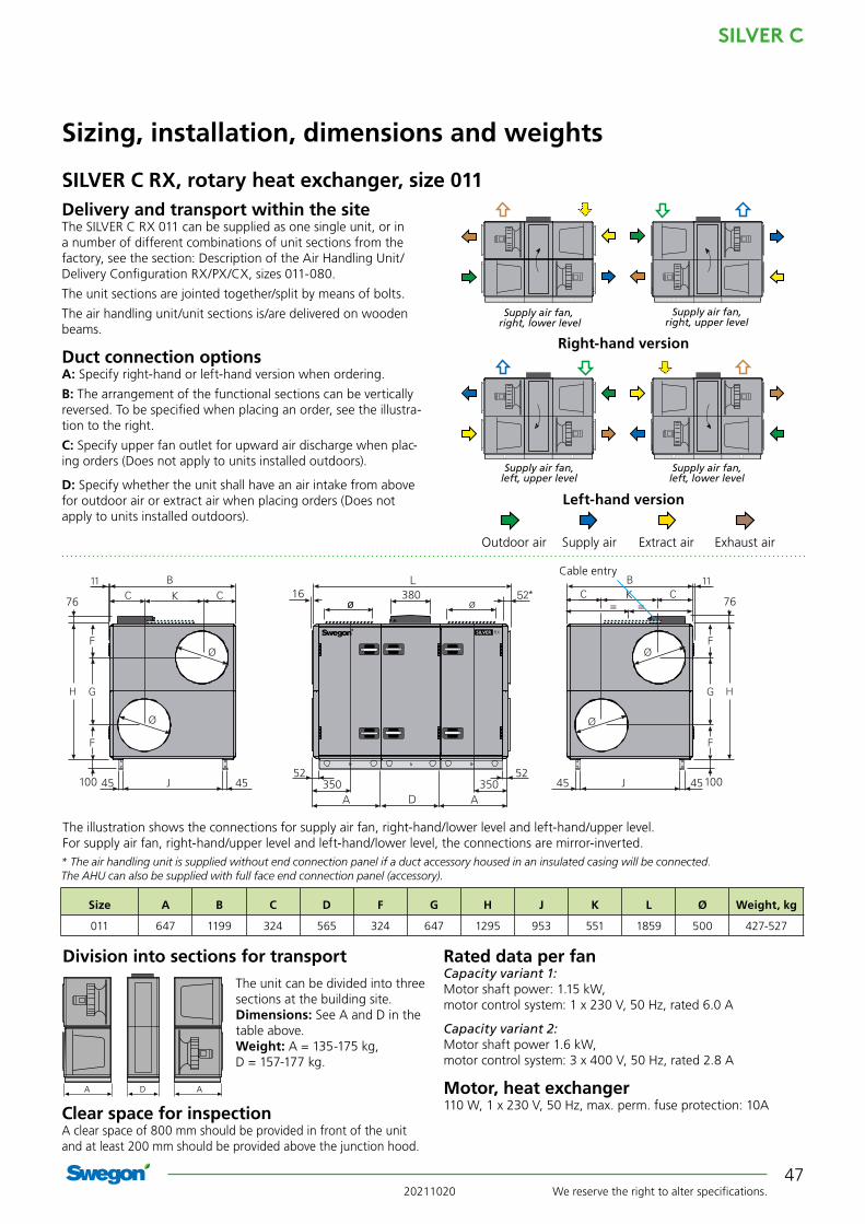
SILVER C RX, rotary heat exchanger, size 011
Sizing, installation, dimensions and weights
Size Min. flow (For units operating in the airflow reg. mode)
Max. airflow
m3/h m3/s m3/h m3/s011 720 0,20 3960 1,10
* The integral attenuation of filters and rotary heat exchanger has been taken into account.** Total sound power level emitted to the surroundings is calculated as the sum of the levels
in the supply air and the extract air.
Rangein
diagram
Octave band, no./mid-frequency, Hz
Sound path 1 2 3 4 5 6 7 8
63 125 250 500 1000 2000 4000 8000
To the outletduct
1 -1 -6 -6 -8 -7 -7 -12 -152 -1 -5 -8 -8 -7 -9 -13 -163 -1 -2 -6 -15 -14 -16 -22 -254 -2 -3 -5 -13 -13 -14 -20 -25
To the inletduct*
1 -6 -9 -12 -22 -31 -33 -38 -372 -7 -10 -17 -18 -29 -31 -37 -383 -6 -4 -14 -27 -35 -39 -44 -434 -7 -5 -12 -22 -34 -36 -42 -43
To unit’s surroundings**
1 -12 -20 -29 -29 -40 -40 -46 -462 -12 -19 -31 -29 -40 -42 -47 -473 -12 -16 -29 -36 -47 -49 -56 -564 -13 -17 -28 -34 -46 -47 -54 -56
Recommended working range for sizing.
Permissible operating range when the fan is controlled to operate at a lower speed. The lower limit for the airflow when the unit is operating in the airflow regulation mode; see the black broken line in the diagram. If pressure regulation is used, the airflow can be regulated to zero, however this presupposes a certain static pressure drop in the ducting (approx. 50 Pa).
2.5
2.0
1.5
7odB 75 85Lw,tot
70dB 75 80 85
90
Lw,tot
123
4
1
23
4
80
Supply air fan
Extract air fan
SFPv
Air flow, m3/s
Ava
ilab
le t
ota
l pre
ssu
re r
ise,
Pa
Air flow, m3/h
The lower limit for the air flow when the unit is operating in the air flow regulation mode.
Cap. var. 1
Cap. var. 2
Cap. var. 1
Cap. var. 2
The air handling unit complies with requirements to Ecodesign 2016/2018.
STE
20211020 We reserve the right to alter specifications.
SILVER C
47
A AD
45 45J
K7616
45 45J
76ø
5252
ø ø
350 350
= =K380
SILVER C RX, rotary heat exchanger, size 011
Sizing, installation, dimensions and weights
Delivery and transport within the siteThe SILVER C RX 011 can be supplied as one single unit, or in a number of different combinations of unit sections from the factory, see the section: Description of the Air Handling Unit/Delivery Configuration RX/PX/CX, sizes 011-080.
The unit sections are jointed together/split by means of bolts.
The air handling unit/unit sections is/are delivered on wooden beams.
Duct connection optionsA: Specify right-hand or left-hand version when ordering.
B: The arrangement of the functional sections can be vertically reversed. To be specified when placing an order, see the illustra-tion to the right.
C: Specify upper fan outlet for upward air discharge when plac-ing orders (Does not apply to units installed outdoors).
D: Specify whether the unit shall have an air intake from above for outdoor air or extract air when placing orders (Does not apply to units installed outdoors).
Right-hand version
Left-hand version
Outdoor air Supply air Extract air Exhaust air
Rated data per fanCapacity variant 1: Motor shaft power: 1.15 kW, motor control system: 1 x 230 V, 50 Hz, rated 6.0 A
Capacity variant 2: Motor shaft power 1.6 kW, motor control system: 3 x 400 V, 50 Hz, rated 2.8 A
Motor, heat exchanger110 W, 1 x 230 V, 50 Hz, max. perm. fuse protection: 10A
The unit can be divided into three sections at the building site.Dimensions: See A and D in the table above.Weight: A = 135-175 kg, D = 157-177 kg.
Division into sections for transport
Clear space for inspectionA clear space of 800 mm should be provided in front of the unit and at least 200 mm should be provided above the junction hood.
Size A B C D F G H J K L Ø Weight, kg
011 647 1199 324 565 324 647 1295 953 551 1859 500 427-527
The illustration shows the connections for supply air fan, right-hand/lower level and left-hand/upper level. For supply air fan, right-hand/upper level and left-hand/lower level, the connections are mirror-inverted.* The air handling unit is supplied without end connection panel if a duct accessory housed in an insulated casing will be connected. The AHU can also be supplied with full face end connection panel (accessory).
Cable entry
Supply air fan, right, lower level
Supply air fan, right, upper level
Supply air fan, left, upper level
Supply air fan, left, lower level

SILVER C
We reserve the right to alter specifications. 2021102048
2.5
2.0
1.5
65dB 70 75 80 85Lw,tot
65dB 807570Lw,tot
1
2
3
1
2
34
4
2.5
2.0
1.5
1
23
4
1
23
4
70dB 75 80Lw,tot
70dB 75 80 85Lw,tot
90
Min. and max. air flowsThe flows specified refer to those that can be preset in the hand-held terminal. The practical flow limits are determined by the external pressure drop.
SILVER C RX Top, rotary heat exchanger, size 011
Recommended working range for sizing.
Size Min. airflow (for airflow regulation)
Max. airflow
m3/h m3/s m3/h m3/s011 720 0.20 3960 1.10
* The integral attenuation of filters and rotary heat exchanger has been taken into account. ** Total sound power level emitted to the surroundings is calclated as the sum of the levels in the supply air and the extract air.
SFPv
Air flow, m3/s
Ava
ilab
le t
ota
l pre
ssu
re r
ise,
Pa
Air flow, m3/h
The lower limit for the air flow when the unit is operating in the air flow regulation mode.
Cap. var. 1
Cap. var. 2
Cap. var. 1
Cap. var. 2
Areain
diagram
Octave band, no./mid-frequency, Hz
Sound path 1 2 3 4 5 6 7 8
63 125 250 500 1000 2000 4000 8000
To the outletduct
1 -2 -6 -3 -11 -13 -13 -18 -232 -2 -7 -12 -3 -10 -11 -15 -193 1 -1 -7 -15 -18 -19 -27 -324 3 -3 -5 -11 -15 -16 -23 -28
To the inletduct*
1 -5 -8 -17 -27 -37 -36 -44 -542 -10 -16 -26 -19 -35 -35 -42 -543 -6 -7 -20 -33 -43 -44 -53 -614 -7 -9 -18 -28 -40 -41 -48 -55
To unit’s surroundings**
1 -13 -20 -26 -32 -46 -46 -52 -542 -13 -21 -35 -24 -43 -44 -49 -503 -10 -15 -30 -36 -51 -52 -61 -634 -8 -17 -28 -32 -48 -49 -57 -59
The air handling unit complies with requirements to Ecodesign 2016/2018.
Left-hand version, STE Right-hand version, STE
SFPv
Air flow, m3/s
Ava
ilab
le t
ota
l pre
ssu
re r
ise,
Pa
Cap. var. 1
Cap. var. 2
Cap. var. 1
Cap. var. 2
Correction factors, KOK, dB. Fan in upper level.
Correction factors, KOK, dB. Fan in lower level.
Areain
diagram
Octave band, no./mid-frequency, Hz
Sound path 1 2 3 4 5 6 7 8
63 125 250 500 1000 2000 4000 8000To the outletduct
1 -6 -16 -1 -16 -17 -17 -24 -332 0 -10 -11 -3 -9 -11 -15 -233 6 -3 -5 -11 -14 -15 -24 -344 5 -5 -4 -8 -12 -14 -22 -31
To the inletduct*
1 -3 -6 -17 -26 -37 -39 -48 -542 -4 -10 -22 -13 -30 -32 -40 -493 6 2 -13 -22 -34 -37 -47 -524 3 -1 -12 -19 -33 -36 -43 -48
To unit’s surroundings**
1 -17 -30 -24 -37 -50 -50 -58 -642 -11 -24 -34 -24 -42 -44 -49 -543 -5 -17 -28 -32 -47 -48 -58 -654 -6 -19 -27 -29 -45 -47 -56 -62
Supply air fan
Extract air fan
Supply air fan
Extract air fan
Permissible operating range when the fan is controlled to operate at a lower speed. The lower limit for the airflow when the unit is operating in the airflow regulation mode; see the black broken line in the diagram. If pressure regulation is used, the airflow can be regulated to zero, however this presupposes a certain static pressure drop in the ducting (approx. 50 Pa).
Sizing, installation, dimensions and weights

20211020 We reserve the right to alter specifications.
SILVER C
49
16 52
D
52 45 45
J
FE
FE
I
Iø
ø
ø
ø
76380
Cable entry
Size A B D E F H I J L Ø Weight, kg
011 827 1199 565 332 500 1295 332 953 2219 500 527-549
The unit can be divided into three sections at the building site.Dimensions: See A and D in the table above.Weight: A = 185-186 kg, D = 157-177 kg.
Division into sections for transport
Clear space for inspectionA clear space of 800 mm should be provided in front of the unit and at least 200 mm should be provided above the junction hood.
Rated data per fanCapacity variant 1: Motor shaft power: 1.15 kW, motor control system: 1 x 230 V, 50 Hz, rated 6.0 A
Capacity variant 2: Motor shaft power 1.6 kW, motor control system: 3 x 400 V, 50 Hz, rated 2.8 A
Motor, heat exchanger110 W, 1 x 230 V, 50 Hz, max. perm. fuse protection: 10A
SILVER C RX Top, rotary heat exchanger, size 011
Sizing, installation, dimensions and weights
Delivery and transport within the siteThe SILVER C RX Top 011 can be supplied as one single unit, or in a number of different combinations of unit sections from the factory, see the section: Description of the Air Handling Unit. Filter/fan sections for RX and RX Top can be combined, see the section: Description of the Air Handling Unit.
The unit sections are jointed together/split by means of bolts.
The air handling unit/unit sections is/are delivered on wooden beams.
Duct connection optionsA: All the duct connections are arranged from the top of the air handling unit (the unit must not be installed outdoors).
B: Specify right-hand or left-hand version when ordering.
C: The arrangement of the functional sections can be vertically reversed. To be specified when placing an order, see the illustra-tion to the right.
Outdoor air Supply air Extract air Exhaust air
Right-hand version
Left-hand version
Supply air fan, right, lower level
Supply air fan, right, upper level
Supply air fan, left, upper level
Supply air fan, left, lower level
A AD

SILVER C
We reserve the right to alter specifications. 2021102050
Min. and max. airflowsThe flows specified refer to those that can be preset in the hand-held micro terminal. The practical flow limits are deter-mined by the external pressure drop.
Correction factors, KOK , dB
SILVER C RX, rotary heat exchanger, size 012
Sizing, installation, dimensions and weights
Size Min. flow (For units operating in the airflow reg. mode)
Max. airflow
m3/h m3/s m3/h m3/s012 720 0,20 5040 1,40
* The integral attenuation of filters and rotary heat exchanger has been taken into account.** Total sound power level emitted to the surroundings is calculated as the sum of the levels
in the supply air and the extract air.
Rangein
diagram
Octave band, no./mid-frequency, Hz
Sound path 1 2 3 4 5 6 7 8
63 125 250 500 1000 2000 4000 8000
To the outletduct
1 -1 -6 -6 -8 -7 -7 -12 -152 -1 -5 -8 -8 -7 -9 -13 -163 -1 -2 -6 -15 -14 -16 -22 -25
To the inletduct*
1 -6 -9 -12 -22 -31 -33 -38 -372 -7 -10 -17 -18 -29 -31 -37 -383 -6 -4 -14 -27 -35 -39 -44 -43
To unit’s surroundings**
1 -12 -20 -29 -29 -40 -40 -46 -462 -12 -19 -31 -29 -40 -42 -47 -473 -12 -16 -29 -36 -47 -49 -56 -56
Recommended working range for sizing.Permissible operating range when the fan is controlled to operate at a lower speed. The lower limit for the airflow when the unit is operating in the airflow regulation mode; see the black broken line in the diagram. If pressure regulation is used, the airflow can be regulated to zero, however this presupposes a certain static pressure drop in the ducting (approx. 50 Pa).
Limit line, Ecodesign, 2018
2.5
2.0
1.5
70dB 8075 85
90
Lw,tot
123
123
70dB 80 8575Lw,tot
90
Supply air fan
Extract air fan
SFPv
Air flow, m3/s
Ava
ilab
le t
ota
l pre
ssu
re r
ise,
Pa
Air flow, m3/h
The lower limit for the air flow when the unit is operating in the air flow regulation mode.
Cap. var. 1
Cap. var. 2
Cap. var. 1
Cap. var. 2
The limit line for Ecodesign 2018 is calculated with capacity variant 2. The mean value for supply air and extract air must be within the limit line. The air handling unit complies with requirements to Ecodesign 2016.
STE
20211020 We reserve the right to alter specifications.
SILVER C
51
SILVER C RX, rotary heat exchanger, size 012
Sizing, installation, dimensions and weights
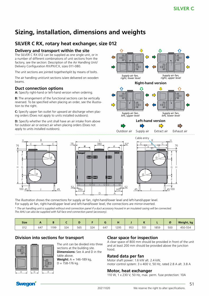
Delivery and transport within the siteThe SILVER C RX 012 can be supplied as one single unit, or in a number of different combinations of unit sections from the factory, see the section: Description of the Air Handling Unit/Delivery Configuration RX/PX/CX, sizes 011-080.
The unit sections are jointed together/split by means of bolts.
The air handling unit/unit sections is/are delivered on wooden beams.
Duct connection optionsA: Specify right-hand or left-hand version when ordering.
B: The arrangement of the functional sections can be vertically reversed. To be specified when placing an order, see the illustra-tion to the right.
C: Specify upper fan outlet for upward air discharge when plac-ing orders (Does not apply to units installed outdoors).
D: Specify whether the unit shall have an air intake from above for outdoor air or extract air when placing orders (Does not apply to units installed outdoors).
Clear space for inspectionA clear space of 800 mm should be provided in front of the unit and at least 200 mm should be provided above the junction hood.
Rated data per fanMotor shaft power: 1.6 kW alt. 2.4 kW, motor control system: 3 x 400 V, 50 Hz, rated 2.8 A alt. 3.8 A
Motor, heat exchanger110 W, 1 x 230 V, 50 Hz, max. perm. fuse protection: 10A
The unit can be divided into three sections at the building site.Dimensions: See A and D in the table above.Weight: A = 146-189 kg, D = 158-176 kg.
Division into sections for transport
Size A B C D F G H J K L Ø Weight, kg
012 647 1199 324 565 324 647 1295 953 551 1859 500 450-554
Right-hand version
Left-hand version
Outdoor air Supply air Extract air Exhaust air
45 45J
K7616
45 45J
76ø
5252
ø ø
350 350
= =K380
The illustration shows the connections for supply air fan, right-hand/lower level and left-hand/upper level. For supply air fan, right-hand/upper level and left-hand/lower level, the connections are mirror-inverted.* The air handling unit is supplied without end connection panel if a duct accessory housed in an insulated casing will be connected. The AHU can also be supplied with full face end connection panel (accessory).
Cable entry
Supply air fan, right, lower level
Supply air fan, right, upper level
Supply air fan, left, upper level
Supply air fan, left, lower level
A AD

SILVER C
We reserve the right to alter specifications. 2021102052
Size Min. airflow (on airflow regulation)
Max. airflow
m3/h m3/s m3/h m3/s012 720 0.20 5040 1.40
SILVER C RX Top, rotary heat exchanger, size 012
Sizing, installation, dimensions and weights
2.5
2.01.5
75dB 80 85 90
95
Lw,tot
65dB 70 75Lw,tot
85
80
1 23
123
2.5
2.01.5
75dB 80
85
Lw,tot
75dB 80 85Lw,tot
95
90
1
23
1
23
Min. and max. air flowsThe flows specified refer to those that can be preset in the hand-held terminal. The practical flow limits are determined by the external pressure drop.
Supply air fan
Extract air fan
SFPv
Air flow, m3/s
Ava
ilab
le t
ota
l pre
ssu
re r
ise,
Pa
Air flow, m3/h
The lower limit for the air flow when the unit is operating in the air flow regulation mode.
Cap. var. 1
Cap. var. 2
Cap. var. 1
Cap. var. 2
Areain
diagram
Octave band, no./mid-frequency, Hz
Sound path 1 2 3 4 5 6 7 8
63 125 250 500 1000 2000 4000 8000
To the outletduct
1 -2 -6 -3 -11 -12 -16 -22 -262 -3 -6 -9 -5 -9 -13 -18 -233 0 -1 -7 -16 -17 -20 -29 -33
To the inletduct*
1 -6 -10 -17 -31 -37 -39 -47 -572 -11 -15 -21 -24 -35 -37 -45 -543 -6 -8 -18 -35 -43 -44 -51 -58
To unit’s surroundings**
1 -13 -20 -26 -32 -45 -49 -56 -572 -14 -20 -32 -26 -42 -46 -52 -543 -11 -15 -30 -37 -50 -53 -63 -64
Left-hand version, STE Right-hand version, STE
Supply air fan
Extract air fan
SFPv
Air flow, m3/s
Ava
ilab
le t
ota
l pre
ssu
re r
ise,
Pa
Cap. var. 1
Cap. var. 2
Cap. var. 1
Cap. var. 2
Correction factors, KOK, dB. Fan in upper level.
Correction factors, KOK, dB. Fan in lower level.
Areain
diagram
Octave band, no./mid-frequency, Hz
Sound path 1 2 3 4 5 6 7 8
63 125 250 500 1000 2000 4000 8000
To the outletduct
1 1 -9 -2 -11 -13 -15 -22 -292 3 -7 -7 -5 -9 -12 -17 -253 6 -3 -6 -10 -13 -16 -26 -34
To the inletduct*
1 4 -1 -14 -22 -32 -35 -42 -512 -3 -8 -19 -17 -30 -33 -40 -473 6 2 -14 -23 -34 -37 -43 -48
To unit’s surroundings**
1 -10 -23 -25 -32 -46 -48 -56 -602 -8 -21 -30 -26 -42 -45 -51 -563 -5 -17 -29 -31 -46 -49 -60 -65
Recommended working range for sizing.Permissible operating range when the fan is controlled to operate at a lower speed. The lower limit for the airflow when the unit is operating in the airflow regulation mode; see the black broken line in the diagram. If pressure regulation is used, the airflow can be regulated to zero, however this presupposes a certain static pressure drop in the ducting (approx. 50 Pa).Limit line, Ecodesign, 2018
For Ecodesign 2018, the mean value for supply air and extract air must be within the limit line.
* The integral attenuation of filters and rotary heat exchanger has been taken into account. ** Total sound power level emitted to the surroundings is calcu-lated as the sum of the levels in the supply air and the extract air.

20211020 We reserve the right to alter specifications.
SILVER C
53
Size A B D E F H I J L Ø Weight, kg
012 827 1199 565 332 500 1295 332 953 2219 500 550-576
The unit can be divided into three sections at the building site.Dimensions: See A and D in the table above.Weight: A = 196-200 kg, D = 158-176 kg.
Division into sections for transport
Sizing, installation, dimensions and weights
SILVER C RX Top, rotary heat exchanger, size 012Delivery and transport within the siteThe SILVER C RX Top 012 can be supplied as one single unit, or in a number of different combinations of unit sections from the factory, see the section: Description of the Air Handling Unit. Filter/fan sections for RX and RX Top can be combined, see the section: Description of the Air Handling Unit.
The unit sections are jointed together/split by means of bolts.
The air handling unit/unit sections is/are delivered on wooden beams.
Duct connection optionsA: All the duct connections are arranged from the top of the air handling unit (the unit must not be installed outdoors).
B: Specify right-hand or left-hand version when ordering.
C: The arrangement of the functional sections can be vertically reversed. To be specified when placing an order, see the illustra-tion to the right.
Outdoor air Supply air Extract air Exhaust air
Right-hand version
Left-hand version
Supply air fan, right, lower level
Supply air fan, right, upper level
Supply air fan, left, upper level
Supply air fan, left, lower level
16 52
D
52 45 45
J
FE
FE
I
Iø
ø
ø
ø
76380
Cable entry
Clear space for inspectionA clear space of 800 mm should be provided in front of the unit and at least 200 mm should be provided above the junction hood.
Rated data per fanMotor shaft power: 1.6 kW alt. 2.4 kW, motor control system: 3 x 400 V, 50 Hz, rated 2.8 A alt. 3.8 A
Motor, heat exchanger110 W, 1 x 230 V, 50 Hz, max. perm. fuse protection: 10A
A AD

SILVER C
We reserve the right to alter specifications. 2021102054
SILVER C RX, rotary heat exchanger, size 014/020Size 014 (Extract air fan size 020 can be selected, see the next page)
Sizing, installation, dimensions and weights
Min. and max. airflowsThe flows specified refer to those that can be preset in the hand-held terminal. The practical flow limits are determined by the external pressure drop.
Correction factors, KOK , dB
Recommended working range for sizing.
Permissible operating range when the fan is controlled to operate at a lower speed. The lower limit for the air flow when the unit is operat-ing in the air flow regulation mode; see the black broken line in the diagram. If pressure regulation is used, the air flow can be regulated to zero. However this presupposes a certain static pressure drop in the ducting (approx. 50 Pa).
Size Min. air flow (on airflow regulation)
Max. air flow
m3/h m3/s m3/h m3/s014 720 0,20 5940 1.65
* The integral attenuation of filters and rotary heat exchanger has been taken into account.
** Total sound power level emitted to the surroundings is calculated as the sum of the levels in the supply air and the extract air.
2.5
2.0
1.5
1 23
1 23
70dB 8075 85 90
90
Lw,tot
70dB 8075 85
90
Lw,tot
Supply air fan
Extract air fan
SFPv
Air flow, m3/s
Ava
ilab
le t
ota
l pre
ssu
re r
ise,
Pa
Air flow, m3/h
The lower limit for the air flow with air flow regulation.
Cap. var. 1
Cap. var. 2
Cap. var. 1
Cap. var. 2
Range in the
diagram
Octave band, no./mid-frequency, Hz
Sound path 1 2 3 4 5 6 7 8
63 125 250 500 1000 2000 4000 8000
To the outletduct
1 -1 -6 -6 -8 -7 -7 -12 -152 -1 -5 -8 -8 -7 -9 -13 -163 -1 -2 -6 -15 -14 -16 -22 -25
To the inletduct*
1 -6 -9 -12 -22 -31 -33 -38 -372 -7 -10 -17 -18 -29 -31 -37 -383 -6 -4 -14 -27 -35 -39 -44 -43
To unit’s surroundings**
1 -12 -20 -29 -29 -40 -40 -46 -462 -12 -19 -31 -29 -40 -42 -47 -473 -12 -16 -29 -36 -47 -49 -56 -56
The air handling unit complies with requirements to Ecodesign 2016/2018.
STE

20211020 We reserve the right to alter specifications.
SILVER C
55
SILVER C RX, rotary heat exchanger, size 014/020Size 020 (Extract air fan size 014 can be selected, see the previous page)
Sizing, installation, dimensions and weights
Min. and max. airflowsThe flows specified refer to those that can be preset in the hand-held terminal. The practical flow limits are determined by the external pressure drop.
Correction factors, KOK , dB
Size Min. air flow (on airflow regulation)
Max. air flow
m3/h m3/s m3/h m3/s020 1080 0.30 7560 2.1
* The integral attenuation of filters and rotary heat exchanger has been taken into account.
** Total sound power level emitted to the surroundings is calculated as the sum of the levels in the supply air and the extract air.
Range in the
diagram
Octave band, no./mid-frequency, Hz
Sound path 1 2 3 4 5 6 7 8
63 125 250 500 1000 2000 4000 8000
To the outlet duct
1 -4 -9 -7 -5 -8 -9 -11 -11
2 2 -4 -7 -7 -10 -12 -16 -17
To the inlet duct*
1 -9 -10 -10 -21 -29 -32 -36 -33
2 -4 -3 -10 -22 -31 -34 -41 -38
To unit’s surroundings**
1 -15 -23 -30 -26 -41 -42 -45 -42
2 -9 -18 -30 -28 -43 -45 -50 -48
2.5
2.0
1.5
70dB 75 80 85Lw,tot
70dB 75 80 85Lw,tot
1
1
2
2
Supply air fan
Extract air fan
SFPv
Air flow, m3/s
Ava
ilab
le t
ota
l pre
ssu
re r
ise,
Pa
Air flow, m3/h
The lower limit for the air flow with air flow regulation.
Cap. var. 1
Cap. var. 2
Cap. var. 1
Cap. var. 2
The limit line for Ecodesign 2018 is calculated with capacity variant 2. The mean value for supply air and extract air must be within the limit line. The air handling unit complies with requirements to Ecodesign 2016.
Recommended working range for sizing.Permissible operating range when the fan is controlled to operate at a lower speed. The lower limit for the airflow when the unit is operating in the airflow regulation mode; see the black broken line in the diagram. If pressure regulation is used, the airflow can be regulated to zero, however this presupposes a certain static pressure drop in the ducting (approx. 50 Pa).Limit line, Ecodesign, 2018
STE

SILVER C
We reserve the right to alter specifications. 2021102056
380 EFF
5252
11
M
M
76
45 45J
SILVER C RX, rotary heat exchanger, size 014/020
Sizing, installation, dimensions and weights
Delivery and transport within the siteThe SILVER C RX 014/020 can be supplied as one single unit, or in a number of different combinations of unit sections from the factory, see the section: Description of the Air Handling Unit. Filter/fan sections for RX and RX Top can be combined, see the section: Description of the Air Handling Unit.
The unit sections are jointed together/split by means of bolts.
The air handling unit/unit sections is/are delivered on wooden beams.
Duct connection optionsA: Specify right-hand or left-hand version when ordering.
B: The arrangement of the functional sections can be vertically reversed. To be specified when placing an order, see the illustra-tion to the right.
C: Specify upper fan outlet for upward air discharge when plac-ing orders (not for outdoor units).
D: Specify whether the unit shall have an air intake from above for outdoor air or extract air when placing orders (does not apply to units installed outdoors).
Right-hand version
Left-hand version
Upward UpwardForwardForward
Upward Upward
ForwardForward
Outdoor air Supply air Extract air Exhaust air
Clear space for inspectionA clear space of 900 mm should be provided in front of the unit and at least 200 mm should be provided above the junction hood.
Rated data per fanSize 014: Motor shaft power 1.6 alt. 2.4 kW, motor control
system 3 x 400 V, 50 Hz, rated 2.8 A alt. 3.8 ASize 020: Motor shaft power 2.4 kW alt. 3.4 kW, motor control
system 3 x 400 V, 50 Hz, rated 4.2 A alt. 5.9 A
Motor, heat exchanger110 W, 1 x 230 V, 50 Hz, max. perm. fuse protection: 10A
The unit can be divided into three sections at the building site.Dimensions: See A and D in the table above.Weight: A = 190-264 kg, D = 192-218 kg.
Division into sections for transport
A AD
Size A B D E F G H I J K L M Weight, kg
014/020 757,5 1400 565 205 400 1000 1551 375 1154 200 2080 188 572-746
Supply air fan, right, lower level
Supply air fan, right, upper level
Supply air fan, left, upper level
Supply air fan, left, lower level
Electrical connection
* The air handling unit is supplied without end connection panel if a duct accessory housed in an insulated casing will be connected. The AHU can also be supplied with full face end connection panel (accessory).

20211020 We reserve the right to alter specifications.
SILVER C
57
2.5
2.0
1.5
1
2
3
1
2
3
70dB 8075 85 90Lw,tot
70dB 75 80 85Lw,tot
90
2.5
2.0
1.5
1
23
1
23
75dB 80 85
90
Lw,tot
75dB 80 8590
Lw,tot
Min. and max. airflowsThe flows specified refer to those that can be preset in the hand-held terminal. The practical flow limits are determined by the external pressure drop.
Size Min. air flow (on airflow regulation)
Max. air flow
m3/h m3/s m3/h m3/s014 720 0,20 5940 1.65
Left-hand version, STE
Supply air fan
Extract air fan
SFPv
Air flow, m3/s
Ava
ilab
le t
ota
l pre
ssu
re r
ise,
Pa
Air flow, m3/h
The lower limit for the air flow with air flow regulation.
Right-hand version, STE
Supply air fan
Extract air fan
SFPv
Air flow, m3/s
Ava
ilab
le t
ota
l pre
ssu
re r
ise,
Pa
Air flow, m3/h
The lower limit for the air flow with air flow regulation.
* The integral attenuation of filters and rotary heat exchanger has been taken into account.
** Total sound power level emitted to the surroundings is calculated as the sum of the levels in the supply air and the extract air.
Range in the
diagram
Octave band, no./mid-frequency, Hz
Sound path 1 2 3 4 5 6 7 8
63 125 250 500 1000 2000 4000 8000To the outlet duct
1 -9 -12 -4 -8 -8 -11 -15 -192 -10 -13 -13 -2 -8 -13 -17 -193 -2 -4 -6 -10 -10 -15 -22 -28
To the inlet duct*
1 -12 -15 -18 -27 -26 -27 -22 -242 -18 -19 -21 -30 -30 -30 -25 -273 -8 -9 -23 -32 -33 -35 -32 -34
To unit’s surroundings**
1 -20 -26 -27 -29 -41 -44 -49 -502 -21 -27 -36 -23 -41 -46 -51 -503 -13 -18 -29 -31 -43 -48 -56 -59
Recommended working range for sizing.Permissible operating range when the fan is controlled to operate at a lower speed. The lower limit for the air flow when the unit is operating in the air flow regulation mode; see the black broken line in the diagram. If pressure regulation is used, the air flow can be regulated to zero. However this presupposes a certain static pressure drop in the ducting (approx. 50 Pa).
SILVER C RX Top, rotary heat exchanger, size 014/020Size 014 (Extract air fan size 020 can be selected, see the next page)
Sizing, installation, dimensions and weights
Correction factors, KOK, dB. Fan in upper level.
Correction factors, KOK, dB. Fan in lower level.
Range in the
diagram
Octave band, no./mid-frequency, Hz
Sound path 1 2 3 4 5 6 7 8
63 125 250 500 1000 2000 4000 8000To the outlet duct
1 -10 -16 -3 -8 -9 -12 -14 -162 -8 -14 -9 -5 -5 -11 -13 -173 -1 -6 -4 -9 -10 -15 -21 -25
To the inlet duct*
1 -11 -14 -19 -23 -25 -25 -20 -232 -12 -14 -19 -21 -25 -23 -19 -223 -7 -7 -18 -27 -31 -30 -29 -32
To unit’s surroundings**
1 -21 -30 -26 -29 -42 -45 -48 -472 -19 -28 -32 -26 -38 -44 -47 -483 -12 -20 -27 -30 -43 -48 -55 -56
Cap. var. 1
Cap. var. 2
Cap. var. 1
Cap. var. 2
Cap. var. 1
Cap. var. 2
Cap. var. 1
Cap. var. 2
The air handling unit complies with requirements to Ecodesign 2018.
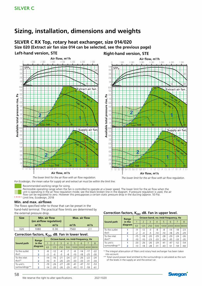
SILVER C
We reserve the right to alter specifications. 2021102058
2.5
2.01.5
75dB 9080 85Lw,tot
75dB
90
80 85Lw,tot
1
1
2
2
95
95
2.5
2.01.5
75dB 9080 85Lw,tot
75dB 9080 85Lw,tot
1
1
2
2
95
95
Cap. var. 1
Cap. var. 2
Cap. var. 1
Cap. var. 2
Cap. var. 1
Cap. var. 2
Cap. var. 1
Cap. var. 2
SILVER C RX Top, rotary heat exchanger, size 014/020Size 020 (Extract air fan size 014 can be selected, see the previous page)
Sizing, installation, dimensions and weights
Min. and max. airflowsThe flows specified refer to those that can be preset in the hand-held terminal. The practical flow limits are determined by the external pressure drop.
Size Min. air flow (on airflow regulation)
Max. air flow
m3/h m3/s m3/h m3/s020 1080 0.30 7560 2.1
Left-hand version, STE
Supply air fan
Extract air fan
SFPv
Air flow, m3/s
Ava
ilab
le t
ota
l pre
ssu
re r
ise,
Pa
Air flow, m3/h
The lower limit for the air flow with air flow regulation.
Right-hand version, STE
Supply air fan
Extract air fan
SFPv
Air flow, m3/s
Ava
ilab
le t
ota
l pre
ssu
re r
ise,
Pa
Air flow, m3/h
The lower limit for the air flow with air flow regulation.
* The integral attenuation of filters and rotary heat exchanger has been taken into account.
** Total sound power level emitted to the surroundings is calculated as the sum of the levels in the supply air and the extract air.
Range in the
diagram
Octave band, no./mid-frequency, Hz
Sound path 1 2 3 4 5 6 7 8
63 125 250 500 1000 2000 4000 8000
To the outlet duct
1 -9 -12 -3 -8 -8 -14 -18 -232 -2 -4 -5 -10 -10 -18 -25 -29
To the inlet duct*
1 -15 -18 -20 -29 -28 -29 -24 -262 -10 -10 -23 -33 -34 -35 -33 -35
To unit’s surroundings**
1 -20 -26 -26 -29 -41 -47 -52 -542 -13 -18 -28 -31 -43 -51 -59 -60
For Ecodesign, the mean value for supply air and extract air must be within the limit line.
Correction factors, KOK, dB. Fan in upper level.
Correction factors, KOK, dB. Fan in lower level.
Range in the
diagram
Octave band, no./mid-frequency, Hz
Sound path 1 2 3 4 5 6 7 8
63 125 250 500 1000 2000 4000 8000
To the outlet duct
1 -8 -12 -4 -7 -8 -14 -17 -222 -3 -6 -3 -8 -10 -18 -25 -30
To the inlet duct*
1 -14 -16 -21 -24 -27 -26 -22 -242 -10 -9 -20 -29 -33 -33 -31 -34
To unit’s surroundings**
1 -19 -26 -27 -28 -41 -47 -51 -532 -14 -20 -26 -29 -43 -51 -59 -61
Recommended working range for sizing.Permissible operating range when the fan is controlled to operate at a lower speed. The lower limit for the air flow when the unit is operating in the air flow regulation mode; see the black broken line in the diagram. If pressure regulation is used, the air flow can be regulated to zero. However this presupposes a certain static pressure drop in the ducting (approx. 50 Pa).Limit line, Ecodesign, 2018

20211020 We reserve the right to alter specifications.
SILVER C
59
SILVER C RX Top, rotary heat exchanger, size 014/020Delivery and transport within the siteThe SILVER C RX Top 014/020 can be supplied as one single unit, or in a number of different combinations of unit sections from the factory, see the section: Description of the Air Han-dling Unit. Filter/fan sections for RX and RX Top can be com-bined, see the section: Description of the Air Handling Unit.
The unit sections are jointed together/split by means of bolts.
The air handling unit/unit sections is/are delivered on wooden beams.
Duct connection optionsA: All the duct connections are arranged from the top of the air handling unit (the unit must not be installed outdoors).
B: Specify right-hand or left-hand version when ordering..
C: The arrangement of the functional sections can be vertically reversed. To be specified when placing an order, see the illustra-tion to the right.
The unit can be divided into three sections at the building site.Dimensions: See A and D in the table above.Weight: A = 267-307 kg, D = 192-218 kg.
Division into sections for transport
A AD
Sizing, installation, dimensions and weights
380
M M KFFE I I
G
O P
N
5252 45 45J
B 11
100
21
G
O P
N
MMK F F EII
76
Size A B D E F G H I J K L M N O P Weight, kg
014/020 1039 1400 565 120 400 1000 1551 106 1154 165 2643 300 1200 200 100 726-832
Outdoor air Supply air Extract air Exhaust air
Electrical connection
Supply air fan, left, upper level
Supply air fan, left, lower level
Supply air fan, right, lower level
Supply air fan, right, upper level
Right-hand version
Left-hand version
View from above. Shows the air handling unit’s duct connections for supply air fan right up and left down
View from above. Shows the air handling unit’s duct connections for supply air fan right down and left up
Clear space for inspectionA clear space of 900 mm should be provided in front of the unit and at least 200 mm should be provided above the junction hood.
Rated data per fanSize 014: Motor shaft power 1.6 alt. 2.4 kW, motor control
system 3 x 400 V, 50 Hz, rated 2.8 A alt. 3.8 ASize 020: Motor shaft power 2.4 kW alt. 3.4 kW, motor control
system 3 x 400 V, 50 Hz, rated 4.2 A alt. 5.9 A
Motor, heat exchanger110 W, 1 x 230 V, 50 Hz, max. perm. fuse protection: 10A
380
M M KFFE I I
G
O P
N
5252 45 45J
B 11
100
21
G
O P
N
MMK F F EII
76

SILVER C
We reserve the right to alter specifications. 2021102060
SILVER C RX, rotary heat exchanger, size 025/030Size 025 (Extract air fan size 030 can be selected, see the next page)
Sizing, installation, dimensions and weights
Min. and max. airflowsThe flows specified refer to those that can be preset in the hand-held terminal. The practical flow limits are determined by the external pressure drop.
Correction factors, KOK , dB
Size Min. air flow (on airflow regulation)
Max. air flow
m3/h m3/s m3/h m3/s025 1080 0.30 9000 2,50
* The integral attenuation of filters and rotary heat exchanger has been taken into account.
** Total sound power level emitted to the surroundings is calculated as the sum of the levels in the supply air and the extract air.
Range in the
diagram
Octave band, no./mid-frequency, Hz
Sound path 1 2 3 4 5 6 7 8
63 125 250 500 1000 2000 4000 8000
To the outlet duct
1 -4 -9 -7 -5 -8 -9 -11 -11
2 2 -4 -7 -7 -10 -12 -16 -17
To the inlet duct*
1 -9 -10 -10 -21 -29 -32 -36 -33
2 -4 -3 -10 -22 -31 -34 -41 -38
To unit’s surroundings**
1 -15 -23 -30 -26 -41 -42 -45 -42
2 -9 -18 -30 -28 -43 -45 -50 -48
2.5
2.01.5
70dB 75 80 85
90
Lw,tot
70dB 75 80 85Lw,tot
12
12
Supply air fan
Extract air fan
SFPv
Air flow, m3/s
Ava
ilab
le t
ota
l pre
ssu
re r
ise,
Pa
Air flow, m3/h
The lower limit for the air flow with air flow regulation.
Cap. var. 1
Cap. var. 2
Cap. var. 1
Cap. var. 2
Recommended working range for sizing.Permissible operating range when the fan is controlled to operate at a lower speed. The lower limit for the air flow when the unit is operating in the air flow regulation mode; see the black broken line in the diagram. If pressure regulation is used, the air flow can be regulated to zero. However this presupposes a certain static pressure drop in the ducting (approx. 50 Pa).
The limit line for Ecodesign 2018 is calculated with capacity variant 2. The mean value for supply air and extract air must be within the limit line. The air handling unit complies with requirements to Ecodesign 2016.
Limit line, Ecodesign, 2018
STE

20211020 We reserve the right to alter specifications.
SILVER C
61
SILVER C RX, rotary heat exchanger, size 025/030Size 030 (Extract air fan size 025 can be selected, see the previous page)
Sizing, installation, dimensions and weights
Min. and max. airflowsThe flows specified refer to those that can be preset in the hand-held terminal. The practical flow limits are determined by the external pressure drop.
Correction factors, KOK , dB
Size Min. air flow (on airflow regulation)
Max. air flow
m3/h m3/s m3/h m3/s030 1800 0,50 11520 3,20
* The integral attenuation of filters and rotary heat exchanger has been taken into account.
** Total sound power level emitted to the surroundings is calculated as the sum of the levels in the supply air and the extract air.
Range in the
diagram
Octave band, no./mid-frequency, Hz
Sound path 1 2 3 4 5 6 7 8
63 125 250 500 1000 2000 4000 8000
To the outlet duct
1 -4 -9 -7 -5 -8 -9 -11 -11
2 2 -4 -7 -7 -10 -12 -16 -17
To the inlet duct*
1 -9 -10 -10 -21 -29 -32 -36 -33
2 -4 -3 -10 -22 -31 -34 -41 -38
To unit’s surroundings**
1 -15 -23 -30 -26 -41 -42 -45 -42
2 -9 -18 -30 -28 -43 -45 -50 -48
2.5
2.01.5
70dB 75 80 8590
Lw,tot
70dB 75 80 85
90
Lw,tot
1
2
1
2
Supply air fan
Extract air fan
SFPv
Air flow, m3/s
Ava
ilab
le t
ota
l pre
ssu
re r
ise,
Pa
Air flow, m3/h
The lower limit for the air flow with air flow regulation.
Cap. var. 1
Cap. var. 2
Cap. var. 1
Cap. var. 2
Recommended working range for sizing.Permissible operating range when the fan is controlled to operate at a lower speed. The lower limit for the air flow when the unit is operating in the air flow regulation mode; see the black broken line in the diagram. If pressure regulation is used, the air flow can be regulated to zero. However this presupposes a certain static pressure drop in the ducting (approx. 50 Pa).
The limit line for Ecodesign is calculated with capacity variant 2. The mean value for supply air and extract air must be within the limit line.
Limit line, Ecodesign, 2016 Limit line, Ecodesign, 2018
STE

SILVER C
We reserve the right to alter specifications. 2021102062
E
M
11
M
525245 45J
SILVER C RX, rotary heat exchanger, size 025/030
Sizing, installation, dimensions and weights
Clear space for inspectionA clear space of 900 mm should be provided in front of the unit.
Rated data per fanSize 025: Motor shaft power 2.4 kW alt. 3.4 kW, motor control
system 3 x 400 V, 50 Hz, rated 4.2 A alt. 5.9 ASize 030: Motor shaft power 4.0 kW alt. 5.0 kW, motor control
system 3 x 400 V, 50 Hz, rated 7.3 A alt. 8.9
Motor, heat exchanger110 W, 1 x 230 V, 50 Hz, max. perm. fuse protection: 10A
The unit can be divided into three sections at the building site.Dimensions: See A and D in the table above.Weight: A = 249-345 kg, D = 246-281 kg.
Division into sections for transport
Size A B D E F G H I J K L M Weight, kg
025/030 848 1600 565 200 500 1200 1811 405 1354 200 2261 203 744-971
A AD
Delivery and transport within the siteThe SILVER C RX 025/030 can be supplied as one single unit, or in a number of different combinations of unit sections from the factory, see the section: Description of the Air Handling Unit. Filter/fan sections for RX and RX Top can be combined, see the section: Description of the Air Handling Unit.
The unit sections are jointed together/split by means of bolts.
The air handling unit/unit sections is/are delivered on wooden beams.
Duct connection optionsA: Specify right-hand or left-hand version when ordering.
B: The arrangement of the functional sections can be vertically reversed. To be specified when placing an order, see the illustra-tion to the right.
C: Specify upper fan outlet for upward air discharge when plac-ing orders (not for outdoor units).
D: Specify whether the unit shall have an air intake from above for outdoor air or extract air when placing orders (does not apply to units installed outdoors).
Right-hand version
Left-hand version
Upward UpwardForwardForward
Upward Upward
ForwardForward
Outdoor air Supply air Extract air Exhaust air
Supply air fan, right, lower level
Supply air fan, right, upper level
Supply air fan, left, upper level
Supply air fan, left, lower level
Electrical connection
* The air handling unit is supplied without end connection panel if a duct accessory housed in an insulated casing will be connected. The AHU can also be supplied with full face end connection panel (accessory).

20211020 We reserve the right to alter specifications.
SILVER C
63
2.5
2.0
1.5
75dB 9080 85Lw,tot
75dB 80 85
90
Lw,tot
1
1
2
2
95
2.5
2.0
1.5
75dB 9080 85Lw,tot
75dB 80 85 90Lw,tot
1
1
2
2
95
Cap. var. 1
Cap. var. 2
Cap. var. 1
Cap. var. 2
Cap. var. 1
Cap. var. 2
Cap. var. 1
Cap. var. 2
SILVER C RX Top, rotary heat exchanger, size 025/030Size 025 (Extract air fan size 030 can be selected, see the next page)
Sizing, installation, dimensions and weights
Min. and max. airflowsThe flows specified refer to those that can be preset in the hand-held terminal. The practical flow limits are determined by the external pressure drop.
Size Min. air flow (on airflow regulation)
Max. air flow
m3/h m3/s m3/h m3/s025 1080 0.30 9000 2,50
Left-hand version, STE
Supply air fan
Extract air fan
SFPv
Air flow, m3/s
Ava
ilab
le t
ota
l pre
ssu
re r
ise,
Pa
Air flow, m3/h
The lower limit for the air flow with air flow regulation.
Right-hand version, STE
Supply air fan
Extract air fan
SFPv
Air flow, m3/s
Ava
ilab
le t
ota
l pre
ssu
re r
ise,
Pa
Air flow, m3/h
The lower limit for the air flow with air flow regulation.
* The integral attenuation of filters and rotary heat exchanger has been taken into account.
** Total sound power level emitted to the surroundings is calculated as the sum of the levels in the supply air and the extract air.
Range in the
diagram
Octave band, no./mid-frequency, Hz
Sound path 1 2 3 4 5 6 7 8
63 125 250 500 1000 2000 4000 8000
To the outlet duct
1 -8 -12 -4 -7 -7 -12 -17 -202 -2 -4 -5 -9 -10 -18 -25 -29
To the inlet duct*
1 -14 -15 -18 -30 -32 -35 -43 -442 -12 -11 -23 -35 -37 -41 -47 -46
To unit’s surroundings**
1 -19 -26 -27 -28 -40 -45 -51 -512 -13 -18 -28 -30 -43 -51 -59 -60
For Ecodesign, the mean value for supply air and extract air must be within the limit line.
Correction factors, KOK, dB. Fan in upper level.
Correction factors, KOK, dB. Fan in lower level.
Range in the
diagram
Octave band, no./mid-frequency, Hz
Sound path 1 2 3 4 5 6 7 8
63 125 250 500 1000 2000 4000 8000
To the outlet duct
1 -9 -13 -6 -6 -6 -12 -16 -192 -4 -5 -4 -8 -10 -18 -25 -28
To the inlet duct*
1 -11 -13 -15 -26 -30 -31 -36 -362 -8 -9 -21 -31 -36 -37 -40 -40
To unit’s surroundings**
1 -20 -27 -29 -27 -39 -45 -50 -502 -15 -19 -27 -29 -43 -51 -59 -59
Recommended working range for sizing.Permissible operating range when the fan is controlled to operate at a lower speed. The lower limit for the air flow when the unit is operating in the air flow regulation mode; see the black broken line in the diagram. If pressure regulation is used, the air flow can be regulated to zero. However this presupposes a certain static pressure drop in the ducting (approx. 50 Pa).Limit line, Ecodesign, 2018

SILVER C
We reserve the right to alter specifications. 2021102064
2.5
2.01.5
75dB
95
85 90Lw,tot
75dB 80 85 90Lw,tot
1
1
2
2
95
2.52.01.5
80dB 90
95
85Lw,tot
80dB 85 90Lw,tot
1
1
2
2 95
Cap. var. 1
Cap. var. 2
Cap. var. 1
Cap. var. 2
Cap. var. 1
Cap. var. 2
Cap. var. 1
Cap. var. 2
Sizing, installation, dimensions and weights
SILVER C RX Top, rotary heat exchanger, size 025/030Size 030 (Extract air fan size 025 can be selected, see the previous page)
Min. and max. airflowsThe flows specified refer to those that can be preset in the hand-held terminal. The practical flow limits are determined by the external pressure drop.
Size Min. air flow (on airflow regulation)
Max. air flow
m3/h m3/s m3/h m3/s030 1800 0,50 11520 3,20
Left-hand version, STE
Supply air fan
Extract air fan
SFPv
Air flow, m3/s
Ava
ilab
le t
ota
l pre
ssu
re r
ise,
Pa
Air flow, m3/h
The lower limit for the air flow with air flow regulation.
Right-hand version, STE
Supply air fan
Extract air fan
SFPv
Air flow, m3/s
Ava
ilab
le t
ota
l pre
ssu
re r
ise,
Pa
Air flow, m3/h
The lower limit for the air flow with air flow regulation.
* The integral attenuation of filters and rotary heat exchanger has been taken into account.
** Total sound power level emitted to the surroundings is calculated as the sum of the levels in the supply air and the extract air.
Range in the
diagram
Octave band, no./mid-frequency, Hz
Sound path 1 2 3 4 5 6 7 8
63 125 250 500 1000 2000 4000 8000
To the outlet duct
1 -9 -11 -3 -7 -9 -14 -17 -182 -1 -3 -6 -9 -11 -19 -24 -26
To the inlet duct*
1 -17 -18 -19 -30 -32 -36 -45 -452 -11 -10 -22 -34 -36 -40 -46 -45
To unit’s surroundings**
1 -20 -25 -26 -28 -42 -47 -51 -492 -12 -17 -29 -30 -44 -52 -58 -57
For Ecodesign, the mean value for supply air and extract air must be within the limit line.
Correction factors, KOK, dB. Fan in upper level.
Correction factors, KOK, dB. Fan in lower level.
Range in the
diagram
Octave band, no./mid-frequency, Hz
Sound path 1 2 3 4 5 6 7 8
63 125 250 500 1000 2000 4000 8000
To the outlet duct
1 -9 -13 -3 -6 -10 -15 -17 -172 -3 -5 -4 -8 -10 -18 -23 -24
To the inlet duct*
1 -15 -17 -17 -28 -33 -34 -40 -402 -8 -8 -20 -31 -35 -36 -38 -39
To unit’s surroundings**
1 -20 -27 -26 -27 -43 -48 -51 -482 -14 -19 -27 -29 -43 -51 -57 -55
Recommended working range for sizing.Permissible operating range when the fan is controlled to operate at a lower speed. The lower limit for the air flow when the unit is operating in the air flow regulation mode; see the black broken line in the diagram. If pressure regulation is used, the air flow can be regulated to zero. However this presupposes a certain static pressure drop in the ducting (approx. 50 Pa).Limit line, Ecodesign, 2018

20211020 We reserve the right to alter specifications.
SILVER C
65
SILVER C RX Top, rotary heat exchanger, size 025/030
Sizing, installation, dimensions and weights
Clear space for inspectionA clear space of 1,000 mm should be provided in front of the unit.
Rated data per fanSize 025: Motor shaft power 2.4 kW alt. 3.4 kW, motor control
system 3 x 400 V, 50 Hz, rated 4.2 A alt. 5.9 ASize 030: Motor shaft power 4.0 kW alt. 5.0 kW, motor control
system 3 x 400 V, 50 Hz, rated 7.3 A alt. 8.9
Motor, heat exchanger 110 W, 1 x 230 V, 50 Hz, max. perm. fuse protection: 10A
The unit can be divided into three sections at the building site.Dimensions: See A and D in the table above.Weight: A = 319-376 kg, D = 246-281 kg.
Division into sections for transport
Size A B D E F G H I J K L M N O P Weight, kg
025/030 1039 1600 565 120 400 1200 1811 106 1354 165 2643 300 1400 200 100 884-1033
Delivery and transport within the siteThe SILVER C RX Top 025/030 can be supplied as one single unit, or in a number of different combinations of unit sections from the factory, see the section: Description of the Air Han-dling Unit. Filter/fan sections for RX and RX Top can be com-bined, see the section: Description of the Air Handling Unit.
The unit sections are jointed together/split by means of bolts.
The air handling unit/unit sections is/are delivered on wooden beams.
Duct connection optionsA: All the duct connections are arranged from the top of the air handling unit (the unit must not be installed outdoors).
B: Specify right-hand or left-hand version when ordering.
C: The arrangement of the functional sections can be vertically reversed. To be specified when placing an order, see the illustra-tion to the right.
Outdoor air Supply air Extract air Exhaust air
21
5252 45 45J
B 35
100
M M KFFE I I
G
O P
N
MMK F F EII
G
O P
N
21
5252 45 45J
B 35
100
M M KFFE I I
G
O P
N
MMK F F EII
G
O P
N
Electrical connection
Supply air fan, left, upper level
Supply air fan, left, lower level
Right-hand version
Left-hand version
View from above. Shows the air handling unit’s duct connections for supply air fan right up and left down
View from above. Shows the air handling unit’s duct connections for supply air fan right down and left up
A AD
Supply air fan, right, lower level
Supply air fan, right, upper level

SILVER C
We reserve the right to alter specifications. 2021102066
SILVER C RX, rotary heat exchanger, size 035/040Size 035 (Extract air fan size 040 can be selected, see the next page)
Sizing, installation, dimensions and weights
Min. and max. airflowsThe flows specified refer to those that can be preset in the hand-held terminal. The practical flow limits are determined by the external pressure drop.
Correction factors, KOK , dB
Size Min. airflow (on airflow regulation)
Max. airflow
m3/h m3/s m3/h m3/s035 1800 0,50 14040 3,90
* The integral attenuation of filters and rotary heat exchanger has been taken into account.** Total sound power level emitted to the surroundings is calculated as the sum of the levels in the supply air and the extract air.
Range in the
diagram
Octave band, no./mid-frequency, Hz
Sound path 1 2 3 4 5 6 7 8
63 125 250 500 1000 2000 4000 8000
To the outlet duct
1 -4 -9 -7 -5 -8 -9 -11 -11
2 2 -4 -7 -7 -10 -12 -16 -17
To the inlet duct*
1 -9 -10 -10 -21 -29 -32 -36 -33
2 -4 -3 -10 -22 -31 -34 -41 -38
To air handling unit surround-ings**
1 -15 -23 -30 -26 -41 -42 -45 -42
2 -9 -18 -30 -28 -43 -45 -50 -48
2.5
2.0
1.5
75dB 80 85 90L w,tot
75dB 80 85 90L w,tot
12
12
Supply air fan
Extract air fan
SFPv
Air flow, m3/s
Ava
ilab
le t
ota
l pre
ssu
re r
ise,
Pa
Air flow, m3/h
The lower limit for the air flow when the unit is operating in the air flow regulation mode.
Cap. var. 1
Cap. var. 2
Cap. var. 1
Cap. var. 2
Recommended working range for sizing.Permissible operating range when the fan is controlled to operate at a lower speed. The lower limit for the air flow when the unit is operating in the air flow regulation mode; see the black broken line in the diagram. If pressure regulation is used, the air flow can be regulated to zero, however this presupposes a certain static pressure drop in the ducting (approx. 50 Pa).
The limit line for Ecodesign 2018 is calculated with capacity variant 2 and full face end connection panels (accessories). The mean value for supply air and extract air must be within the limit line. The air handling unit complies with requirements to Ecodesign 2016. Other values in diagrams are calculated for air handling units with standard end connection panels.
Limit line, Ecodesign, 2018
STE

20211020 We reserve the right to alter specifications.
SILVER C
67
SILVER C RX, rotary heat exchanger, size 035/040Size 040 (Extract air fan size 035 can be selected, see the previous page)
Sizing, installation, dimensions and weights
Min. and max. airflowsThe flows specified refer to those that can be preset in the hand-held terminal. The practical flow limits are determined by the external pressure drop.
Correction factors, KOK , dB
Size Min. airflow (on airflow regulation)
Max. airflow
m3/h m3/s m3/h m3/s040 2700 0,75 18000 5,00
* The integral attenuation of filters and rotary heat exchanger has been taken into account.** Total sound power level emitted to the surroundings is calculated as the sum of the levels in the supply air and the extract air.
Range in the
diagram
Octave band, no./mid-frequency, Hz
Sound path 1 2 3 4 5 6 7 8
63 125 250 500 1000 2000 4000 8000
To the outlet duct
1 -4 -9 -7 -5 -8 -9 -11 -11
2 2 -4 -7 -7 -10 -12 -16 -17
To the inlet duct*
1 -9 -10 -10 -21 -29 -32 -36 -33
2 -4 -3 -10 -22 -31 -34 -41 -38
To air handling unit surround-ings**
1 -15 -23 -30 -26 -41 -42 -45 -42
2 -9 -18 -30 -28 -43 -45 -50 -48
2.5
2.01.5
75dB 80 85 90Lw,tot
75dB 80 85 90Lw,tot
12
12
Supply air fan
Extract air fan
SFPv
Air flow, m3/s
Ava
ilab
le t
ota
l pre
ssu
re r
ise,
Pa
Air flow, m3/h
The lower limit for the air flow when the unit is operating in the air flow regulation mode.
The limit line for Ecodesign is calculated with full face end connection panels (accessories). The mean value for supply air and extract air must be within the limit line. Other values in diagrams are calculated for air handling units with standard end connection panels.
Cap. var. 1
Cap. var. 2
Cap. var. 1
Cap. var. 2
Recommended working range for sizing.Permissible operating range when the fan is controlled to operate at a lower speed. The lower limit for the air flow when the unit is operating in the air flow regulation mode; see the black broken line in the diagram. If pressure regulation is used, the air flow can be regulated to zero, however this presupposes a certain static pressure drop in the ducting (approx. 50 Pa).
STE

SILVER C
We reserve the right to alter specifications. 2021102068
SILVER C RX, rotary heat exchanger, size 035/040
Sizing, installation, dimensions and weights
Delivery and transport within the siteThe SILVER C RX 035/040 can be supplied as one single unit, or in a number of different combinations of unit sections from the factory, see the section: Description of the Air Handling Unit/Delivery Configuration RX/PX/CX, sizes 011-080.
The unit sections are jointed together/split by means of bolts.
The air handling unit/unit sections is/are delivered on wooden beams.
Duct connection optionsA: Specify right-hand or left-hand version when ordering.
B: The arrangement of the functional sections can be vertically reversed. To be specified when placing an order, see the illustra-tion to the right.
C: Specify upper fan outlet for upward air discharge when plac-ing orders (not for outdoor units).
D: Specify whether the unit shall have an air intake from above for outdoor air or extract air when placing orders (Does not apply to units installed outdoors).
The unit can be divided into three sections at the building site.Dimensions: See A and D in the table above.Weight: A = 377-504 kg, D = 342-397 kg.
Division into sections for transport
Cable entry
Size A B D E F G H I J K L M Weight, kg
035/040 1038.5 1990 565 245 600 1400 2159 479 1744 295 2642 240 1096-1405
Outdoor air Supply air Extract air Exhaust air
Upward Upward
ForwardForward
Upward Upward
ForwardForward
Right-hand version
Left-hand version
* The air handling unit is supplied without end connection panel if a duct accessory housed in an insulated casing will be connected. The AHU can also be supplied with full face end connection panel (accessory).
A AD
Clear space for inspectionA clear space of 1100 mm should be provided in front of the unit.
Rated data per fanSize 035: Motor shaft power: 4.0 kW alt. 5.0 kW, motor control system: 3 x 400 V, 50 Hz, rated 7.3 A alt. 8.9 ASize 040: Motor shaft power: 6,5 kW alt. 10 kW, motor control system: 3 x 400 V, 50 Hz, nom. 11.4 A alt. 16 A
Motor, heat exchangerStandard: 110 W, 1 x 230 V, 50 Hz, max. perm. fuse prot.: 10ASorption: 220 W, 1 x 230 V, 50 Hz, max. perm. fuse prot.: 10A
M
M
52 5245 45J
Supply air fan, right, lower level
Supply air fan, right, upper level
Supply air fan, left, upper level
Supply air fan, left, lower level

20211020 We reserve the right to alter specifications.
SILVER C
69
SILVER C RX, rotary heat exchanger, size 050/060Size 050 (Extract air fan size 060 can be selected, see the next page)
Sizing, installation, dimensions and weights
Min. and max. airflowsThe flows specified refer to those that can be preset in the hand-held terminal. The practical flow limits are determined by the external pressure drop.
* The integral attenuation of filters and rotary heat exchanger has been taken into account.** Total sound power level emitted to the surroundings is calculated as the sum of the levels in the supply air and the extract air.
Correction factors, KOK , dB
Range in the
diagram
Octave band, no./mid-frequency, Hz
Sound path 1 2 3 4 5 6 7 8
63 125 250 500 1000 2000 4000 8000
To the outlet duct
1 -4 -9 -7 -5 -8 -9 -11 -11
2 2 -4 -7 -7 -10 -12 -16 -17
To the inlet duct*
1 -9 -10 -10 -21 -29 -32 -36 -33
2 -4 -3 -10 -22 -31 -34 -41 -38
To air handling unit surround-ings**
1 -15 -23 -30 -26 -41 -42 -45 -42
2 -9 -18 -30 -28 -43 -45 -50 -48
Size Min. airflow (on airflow regulation)
Max. airflow
m3/h m3/s m3/h m3/s050 2700 0,75 18000 5,00
2.5
2.0
1.5
75dB 80 85 90Lw,tot
75dB 80 85 90Lw,tot
12
12
Recommended working range for sizing.Permissible operating range when the fan is controlled to operate at a lower speed. The lower limit for the air flow when the unit is operating in the air flow regulation mode; see the black broken line in the diagram. If pressure regulation is used, the air flow can be regulated to zero, however this presupposes a certain static pressure drop in the ducting (approx. 50 Pa).
Supply air fan
Extract air fan
SFPv
Air flow, m3/s
Ava
ilab
le t
ota
l pre
ssu
re r
ise,
Pa
Air flow, m3/h
The lower limit for the air flow when the unit is operating in the air flow regulation mode.
The diagram shows air handling units including standard the end connection panels. The air handling unit complies with requirements to Ecodesign 2016/2018.
Cap. var. 1
Cap. var. 2
Cap. var. 1
Cap. var. 2
STE

SILVER C
We reserve the right to alter specifications. 2021102070
SILVER C RX, rotary heat exchanger, size 050/060Size 060 (Extract air fan size 050 can be selected, see the previous page)
Sizing, installation, dimensions and weights
Min. and max. airflowsThe flows specified refer to those that can be preset in the hand-held terminal. The practical flow limits are determined by the external pressure drop.
Correction factors, KOK , dB
Size Min. airflow (on airflow regulation)
Max. airflow
m3/h m3/s m3/h m3/s060 3600 1,00 23400 6,50
* The integral attenuation of filters and rotary heat exchanger has been taken into account.** Total sound power level emitted to the surroundings is calculated as the sum of the levels in the supply air and the extract air.
Range in the
diagram
Octave band, no./mid-frequency, Hz
Sound path 1 2 3 4 5 6 7 8
63 125 250 500 1000 2000 4000 8000
To the outlet duct
1 -4 -9 -7 -5 -8 -9 -11 -11
2 2 -4 -7 -7 -10 -12 -16 -17
To the inlet duct*
1 -9 -10 -10 -21 -29 -32 -36 -33
2 -4 -3 -10 -22 -31 -34 -41 -38
To air handling unit surround-ings**
1 -15 -23 -30 -26 -41 -42 -45 -42
2 -9 -18 -30 -28 -43 -45 -50 -48
2.5
2.01.5
75dB 80 85 90L w,tot
12
12
75dB 80 85 90L w,tot
The limit line for Ecodesign is calculated with capacity variant 2 and full face end connection panels (accessories). The mean value for supply air and extract air must be within the limit line. Other values in diagrams are calculated for air handling units with standard end connection panels.
Supply air fan
Extract air fan
SFPv
Air flow, m3/s
Ava
ilab
le t
ota
l pre
ssu
re r
ise,
Pa
Air flow, m3/h
The lower limit for the air flow when the unit is operating in the air flow regulation mode.
Recommended working range for sizing.Permissible operating range when the fan is controlled to operate at a lower speed. The lower limit for the air flow when the unit is operating in the air flow regulation mode; see the black broken line in the diagram. If pressure regulation is used, the air flow can be regulated to zero, however this presupposes a certain static pressure drop in the ducting (approx. 50 Pa).Limit line, Ecodesign, 2016 Limit line, Ecodesign, 2018
STE
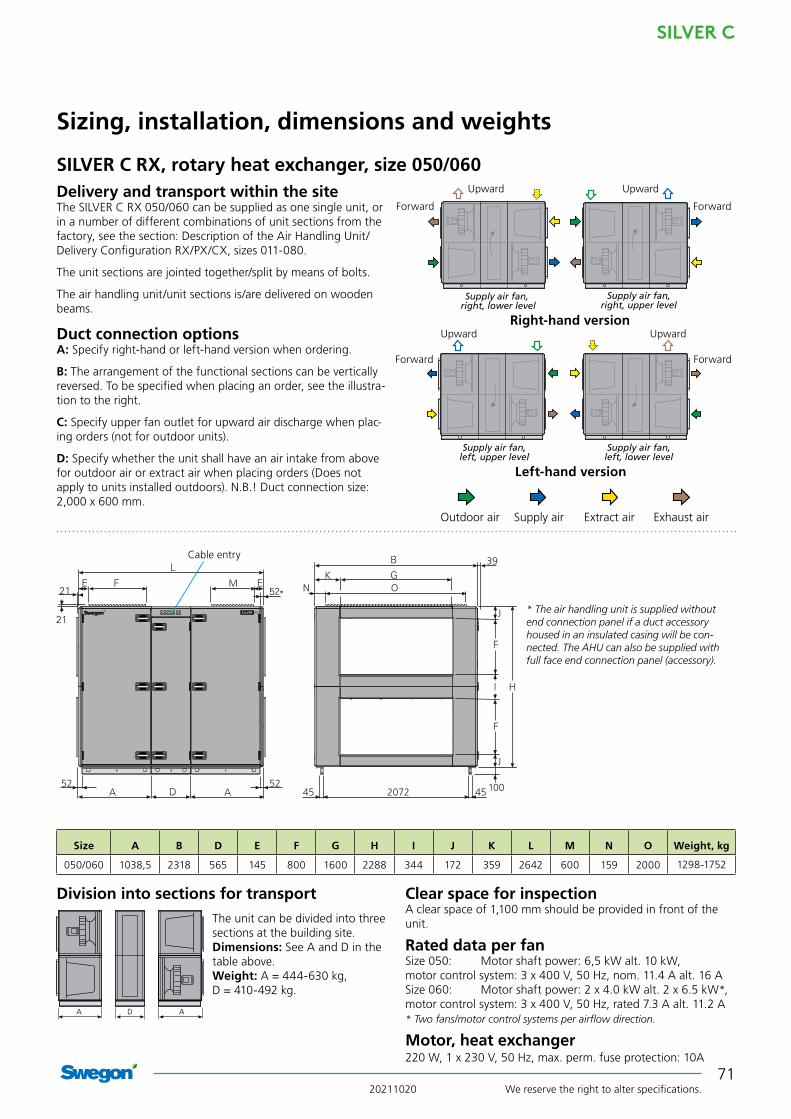
20211020 We reserve the right to alter specifications.
SILVER C
71
J
J
52 52
39
M N O
207245 45
Size A B D E F G H I J K L M N O Weight, kg
050/060 1038,5 2318 565 145 800 1600 2288 344 172 359 2642 600 159 2000 1298-1752
SILVER C RX, rotary heat exchanger, size 050/060
Sizing, installation, dimensions and weights
Delivery and transport within the siteThe SILVER C RX 050/060 can be supplied as one single unit, or in a number of different combinations of unit sections from the factory, see the section: Description of the Air Handling Unit/Delivery Configuration RX/PX/CX, sizes 011-080.
The unit sections are jointed together/split by means of bolts.
The air handling unit/unit sections is/are delivered on wooden beams.
Duct connection optionsA: Specify right-hand or left-hand version when ordering.
B: The arrangement of the functional sections can be vertically reversed. To be specified when placing an order, see the illustra-tion to the right.
C: Specify upper fan outlet for upward air discharge when plac-ing orders (not for outdoor units).
D: Specify whether the unit shall have an air intake from above for outdoor air or extract air when placing orders (Does not apply to units installed outdoors). N.B.! Duct connection size: 2,000 x 600 mm.
Clear space for inspectionA clear space of 1,100 mm should be provided in front of the unit.
Rated data per fanSize 050: Motor shaft power: 6,5 kW alt. 10 kW, motor control system: 3 x 400 V, 50 Hz, nom. 11.4 A alt. 16 ASize 060: Motor shaft power: 2 x 4.0 kW alt. 2 x 6.5 kW*, motor control system: 3 x 400 V, 50 Hz, rated 7.3 A alt. 11.2 A * Two fans/motor control systems per airflow direction.
Motor, heat exchanger220 W, 1 x 230 V, 50 Hz, max. perm. fuse protection: 10A
Division into sections for transport
* The air handling unit is supplied without end connection panel if a duct accessory housed in an insulated casing will be con-nected. The AHU can also be supplied with full face end connection panel (accessory).
A AD
Outdoor air Supply air Extract air Exhaust air
Upward Upward
ForwardForward
Upward Upward
ForwardForward
Right-hand version
Left-hand version
The unit can be divided into three sections at the building site.Dimensions: See A and D in the table above.Weight: A = 444-630 kg, D = 410-492 kg.
Cable entry
Supply air fan, right, lower level
Supply air fan, right, upper level
Supply air fan, left, upper level
Supply air fan, left, lower level
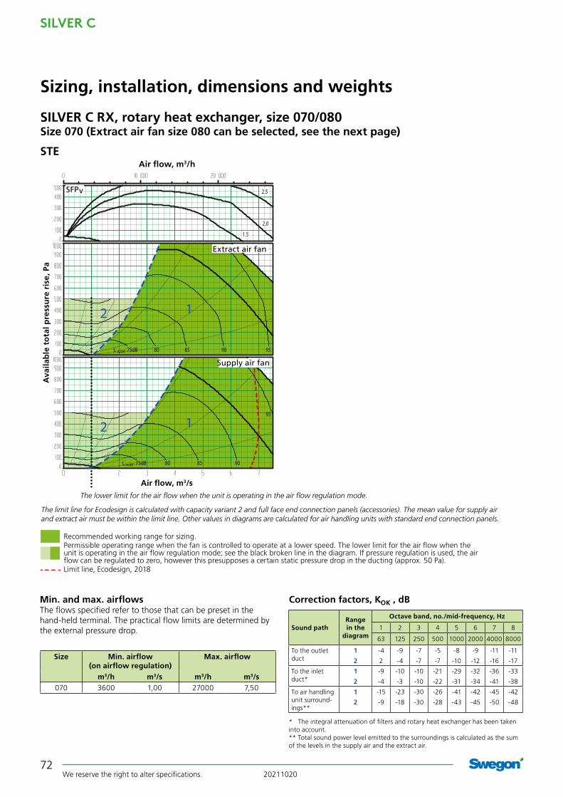
SILVER C
We reserve the right to alter specifications. 2021102072
SILVER C RX, rotary heat exchanger, size 070/080Size 070 (Extract air fan size 080 can be selected, see the next page)
Sizing, installation, dimensions and weights
Min. and max. airflowsThe flows specified refer to those that can be preset in the hand-held terminal. The practical flow limits are determined by the external pressure drop.
Correction factors, KOK , dB
Size Min. airflow (on airflow regulation)
Max. airflow
m3/h m3/s m3/h m3/s070 3600 1,00 27000 7,50
* The integral attenuation of filters and rotary heat exchanger has been taken into account.** Total sound power level emitted to the surroundings is calculated as the sum of the levels in the supply air and the extract air.
Range in the
diagram
Octave band, no./mid-frequency, Hz
Sound path 1 2 3 4 5 6 7 8
63 125 250 500 1000 2000 4000 8000
To the outlet duct
1 -4 -9 -7 -5 -8 -9 -11 -11
2 2 -4 -7 -7 -10 -12 -16 -17
To the inlet duct*
1 -9 -10 -10 -21 -29 -32 -36 -33
2 -4 -3 -10 -22 -31 -34 -41 -38
To air handling unit surround-ings**
1 -15 -23 -30 -26 -41 -42 -45 -42
2 -9 -18 -30 -28 -43 -45 -50 -48
2.5
2.0
1.5
12
12
75dB 80 85 90 95
95
L w,tot
75dB 80 85 90L w,tot
Supply air fan
Extract air fan
SFPv
Air flow, m3/s
Ava
ilab
le t
ota
l pre
ssu
re r
ise,
Pa
Air flow, m3/h
The lower limit for the air flow when the unit is operating in the air flow regulation mode.
Recommended working range for sizing.Permissible operating range when the fan is controlled to operate at a lower speed. The lower limit for the air flow when the unit is operating in the air flow regulation mode; see the black broken line in the diagram. If pressure regulation is used, the air flow can be regulated to zero, however this presupposes a certain static pressure drop in the ducting (approx. 50 Pa).Limit line, Ecodesign, 2018
The limit line for Ecodesign is calculated with capacity variant 2 and full face end connection panels (accessories). The mean value for supply air and extract air must be within the limit line. Other values in diagrams are calculated for air handling units with standard end connection panels.
STE

20211020 We reserve the right to alter specifications.
SILVER C
73
SILVER C RX, rotary heat exchanger, size 070/080Size 080 (Extract air fan size 070 can be selected, see the previous page)
Sizing, installation, dimensions and weights
Min. and max. airflowsThe flows specified refer to those that can be preset in the hand-held terminal. The practical flow limits are determined by the external pressure drop.
Correction factors, KOK , dB
Size Min. airflow (on airflow regulation)
Max. airflow
m3/h m3/s m3/h m3/s080 5400 1,50 34200 9,50
* The integral attenuation of filters and rotary heat exchanger has been taken into account.** Total sound power level emitted to the surroundings is calculated as the sum of the levels in the supply air and the extract air.
Range in the
diagram
Octave band, no./mid-frequency, Hz
Sound path 1 2 3 4 5 6 7 8
63 125 250 500 1000 2000 4000 8000
To the outlet duct
1 -4 -9 -7 -5 -8 -9 -11 -11
2 2 -4 -7 -7 -10 -12 -16 -17
To the inlet duct*
1 -9 -10 -10 -21 -29 -32 -36 -33
2 -4 -3 -10 -22 -31 -34 -41 -38
To air handling unit surround-ings**
1 -15 -23 -30 -26 -41 -42 -45 -42
2 -9 -18 -30 -28 -43 -45 -50 -48
2.5
2.01.5
80dB 85 90 95Lw,tot
80dB 85 90
95
Lw,tot
12
12
Supply air fan
Extract air fan
SFPv
Air flow, m3/s
Ava
ilab
le t
ota
l pre
ssu
re r
ise,
Pa
Air flow, m3/h
The lower limit for the air flow when the unit is operating in the air flow regulation mode.
Cap. var. 1
Cap. var. 2
Cap. var. 1
Cap. var. 2
The limit line for Ecodesign is calculated with capacity variant 2 and full face end connection panels (accessories). The mean value for supply air and extract air must be within the limit line. Other values in diagrams are calculated for air handling units with standard end connection panels.
Recommended working range for sizing.Permissible operating range when the fan is controlled to operate at a lower speed. The lower limit for the air flow when the unit is operating in the air flow regulation mode; see the black broken line in the diagram. If pressure regulation is used, the air flow can be regulated to zero, however this presupposes a certain static pressure drop in the ducting (approx. 50 Pa).Limit line, Ecodesign, 2018
STE

SILVER C
We reserve the right to alter specifications. 2021102074
52 52
76121 1200 1150
45
762485
52*NM O
Size A B D E F G H I J K L M N O Weight, kg
070/080 1273,5 2637 565 162 1000 1800 2640 320 160 418,5 3112 750 118,5 2400 2218-2649
SILVER C RX, rotary heat exchanger, size 070/080
Sizing, installation, dimensions and weights
Delivery and transport within the siteThe SILVER C RX 070/080 can be supplied in two units, or in a number of different combinations of unit sections from the factory, see the section: Description of the Air Handling Unit/Delivery Configuration RX/PX/CX, sizes 011-080.
The unit sections are jointed together/split by means of bolts.
Duct connection optionsA: Specify right-hand or left-hand version when ordering.
B: The arrangement of the functional sections can be vertically reversed. To be specified when placing an order, see the illustra-tion to the right.
C: Specify upper fan outlet for upward air discharge when plac-ing orders (not for outdoor units).
D: Specify whether the unit shall have an air intake from above for outdoor air or extract air when placing orders (Does not apply to units installed outdoors). N.B.! Duct connection size: 2,400 x 750 mm.
A AD
Clear space for inspectionA clear space of 1,100 mm should be provided in front of the unit.
Rated data per fanSize 070: Motor shaft power: 2 x 4.0 kW alt. 2 x 6.5 kW*, motor control system: 3 x 400 V, 50 Hz, rated 7.3 A alt. 11.2 A Size 080: Motor shaft power: 2 x 6.5 kW alt. 2 x 10 kW*, motor control system: 3 x 400 V, 50 Hz, rated 11.5 A alt. 16 A * Two fans/motor control systems per airflow direction.
Motor, heat exchangerSize 070: 220 W, 1 x 230 V, 50 Hz, max. perm. fuse prot. 10A
Size 080: Standard, 220 W, 1 x 230 V, 50 Hz, max. perm. fuse prot.10ASorption, 790 W, 1 x 230 V, 50 Hz, max. perm. fuse prot. 10A
Division into sections for transport
Outdoor air Supply air Extract air Exhaust air
Upward Upward
ForwardForward
Upward Upward
ForwardForward
Right-hand version
Left-hand version
The unit can be divided into three sections at the building site.Dimensions: See A and D in the table above.Weight: A = 786-956 kg, D = 646-737 kg.
Cable entry
* The air handling unit is supplied without end connec-tion panel if a duct accessory housed in an insulated casing will be connected. The AHU can also be supplied with full face end connection panel (accessory).
Supply air fan, right, lower level
Supply air fan, right, upper level
Supply air fan, left, upper level
Supply air fan, left, lower level

20211020 We reserve the right to alter specifications.
SILVER C
75
SILVER C RX, rotary heat exchanger, size 100
Sizing, installation, dimensions and weights
Min. and max. airflowsThe flows specified refer to those that can be preset in the hand-held terminal. The practical flow limits are determined by the external pressure drop.
Size Min. airflow (on airflow regulation)
Max. airflow
m3/h m3/s m3/h m3/s100 5400 1,50 39 600 11,0
Correction factors, KOK , dB
* The integral attenuation of filters and rotary heat exchanger has been taken into account.
** Total sound power level emitted to the surroundings is calculated as the sum of the levels in the supply air and the extract air.
Range in the
diagram
Octave band, no./mid-frequency, Hz
Sound path 1 2 3 4 5 6 7 8
63 125 250 500 1000 2000 4000 8000
To the outlet duct
1 -4 -9 -7 -5 -8 -9 -11 -11
2 2 -4 -7 -7 -10 -12 -16 -17
To the inlet duct*
1 -9 -10 -10 -21 -29 -32 -36 -33
2 -4 -3 -10 -22 -31 -34 -41 -38
To air handling unit surround-ings**
1 -15 -23 -30 -26 -41 -42 -45 -42
2 -9 -18 -30 -28 -43 -45 -50 -48
2.5
2.01.5
80dB 85 90 95Lw,tot
80dB 85 9095
Lw,tot
12
12
Supply air fan
Extract air fan
SFPv
Air flow, m3/s
Ava
ilab
le t
ota
l pre
ssu
re r
ise,
Pa
Air flow, m3/h
The lower limit for the air flow when the unit is operating in the air flow regulation mode.
Cap. var. 1
Cap. var. 2
Cap. var. 1
Cap. var. 2
Recommended working range for sizing.Permissible operating range when the fan is controlled to operate at a lower speed. The lower limit for the air flow when the unit is operating in the air flow regulation mode; see the black broken line in the diagram. If pressure regulation is used, the air flow can be regulated to zero, however this presupposes a certain static pressure drop in the ducting (approx. 50 Pa).
The limit line for Ecodesign 2018 is calculated with capacity variant 2 and full face end connection panels (accessories). The mean value for supply air and extract air must be within the limit line. The air handling unit complies with requirements to Ecodesign 2016. Other values in diagrams are calculated for air handling units with standard end connection panels.
Limit line, Ecodesign, 2018
STE

SILVER C
We reserve the right to alter specifications. 2021102076
Sizing, installation, dimensions and weights
SILVER C RX, rotary heat exchanger, size 100
N O N
P
P
52*
52
M
77 3186 77
1048 1000 1048122
45
Size A B D E F G H I J K L M N O P Weight, kg
100 1122 3340 1070 187 1200 2400 3440 520 210 470 3314 800 420 2500 1720 3324-3910
Cable entry
* The air handling unit is supplied without end connection panel if a duct accessory housed in an insulated casing will be con-nected. The AHU can also be supplied with full face end connec-tion panel (accessory).
Delivery and transport within the siteThe SILVER C RX 100 is supplied in five separate sections: Two fan sections, two filter sections and one heat exchanger section. The heat exchanger section can also be supplied split into two casing sections and rotor, in which case the rotor is supplied tilted in a transport cradle (transport height = 2,930 mm, mini-mum transport width = 2,350 mm). After the heat exchanger section has been assembled, if required, the five sections must be installed at the building site.
The five unit sections are jointed together/split by means of bolts.
Duct connection optionsA: Specify right-hand or left-hand version when ordering.
B: The arrangement of the functional sections can be vertically reversed. To be specified when placing an order, see the illustra-tion to the right.
C: Specify upper fan outlet for upward air discharge when plac-ing orders (not for outdoor units). N.B.! Duct connection size: 2,500 x 800 mm.
Filter and fan sections See dimensions A and P in the table above. Weight: fan section = 644-720 kg, filter section = 402-540 kg.
Heat exchanger section, mountedSee dimensions D and H in the table above. Weight: heat exchanger section = 1232-1390 kg.
Heat exchanger section, supplied in two casing sections + rotorSee transport dimensions in the Delivery and at-site transport section above. Weight: casing lower section = 513 kg, casing upper section = 300 kg, rotor = 428 kg, transport cradle = 190 kg
Transport, dimensions and weights
Upward Upward
ForwardForward
Upward Upward
ForwardForward
Right-hand version
Left-hand version
Outdoor air Supply air Extract air Exhaust air
Clear space for inspectionA clear space of 1,000 mm should be provided in front of the unit.
Rated data per fanMotor shaft power: 2 x 6.5 kW alt. 2 x 10 kW*, motor control system: 3 x 400 V, 50 Hz, rated 11.5 A alt. 16 A* Two fans/motor control systems per airflow direction.
Motor, heat exchanger790 W, 1 x 230 V, 50 Hz, max. perm. fuse protection: 10A
Supply air fan, right, lower level
Supply air fan, right, upper level
Supply air fan, left, upper level
Supply air fan, left, lower level

20211020 We reserve the right to alter specifications.
SILVER C
77
SILVER C RX, rotary heat exchanger, size 120
Sizing, installation, dimensions and weights
Min. and max. airflowsThe flows specified refer to those that can be preset in the hand-held terminal. The practical flow limits are determined by the external pressure drop.
Size Min. airflow (on airflow regulation)
Max. airflow
m3/h m3/s m3/h m3/s120 9000 2,50 50 400 14.0
Correction factors, KOK , dB
* The integral attenuation of filters and rotary heat exchanger has been taken into account.** Total sound power level emitted to the surroundings is calculated as the sum
of the levels in the supply air and the extract air.
Range in the
diagram
Octave band, no./mid-frequency, Hz
Sound path 1 2 3 4 5 6 7 8
63 125 250 500 1000 2000 4000 8000
To the outlet duct
1 -4 -9 -7 -5 -8 -9 -11 -11
2 2 -4 -7 -7 -10 -12 -16 -17
To the inlet duct**
1 -9 -10 -10 -21 -29 -32 -36 -33
2 -4 -3 -10 -22 -31 -34 -41 -38
To air handling unit surround-ings**
1 -15 -23 -30 -26 -41 -42 -45 -42
2 -9 -18 -30 -28 -43 -45 -50 -48
2.5
2.01.5
80dB 85 90 95
80dB 85 9095
Lw,tot
12
12
Lw,tot
SFPv
Air flow, m3/s
Ava
ilab
le t
ota
l pre
ssu
re r
ise,
Pa
Air flow, m3/h
The lower limit for the air flow when the unit is operating in the air flow regulation mode.
Cap. var. 1
Cap. var. 2
Cap. var. 1
Cap. var. 2
The limit line for Ecodesign is calculated with capacity variant 2 and full face end connection panels (accessories). The mean value for supply air and extract air must be within the limit line. Other values in diagrams are calculated for air handling units with standard end connection panels.
Supply air fan
Extract air fan
Recommended working range for sizing.Permissible operating range when the fan is controlled to operate at a lower speed. The lower limit for the air flow when the unit is operating in the air flow regulation mode; see the black broken line in the diagram. If pressure regulation is used, the air flow can be regulated to zero, however this presupposes a certain static pressure drop in the ducting (approx. 50 Pa).Limit line, Ecodesign, 2018
STE

SILVER C
We reserve the right to alter specifications. 2021102078
Sizing, installation, dimensions and weights
SILVER C RX, rotary heat exchanger, size 120
Size A B D E F G H I J K L M N O P Weight, kg
120 1122 3340 1070 187 1200 2400 3440 520 210 470 3314 800 420 2500 1720 3524-4128
N O N
P
P
52*
52
M
77 3186 77
1048 1000 1048122
45
Cable entry
* The air handling unit is supplied without end connection panel if a duct accessory housed in an insulated casing will be con-nected. The AHU can also be supplied with full face end connec-tion panel (accessory).
Delivery and transport within the siteThe SILVER C RX 120 is supplied in five separate sections: Two fan sections, two filter sections and one heat exchanger section. The heat exchanger section can also be supplied split into two casing sections and rotor, in which case the rotor is supplied tilted in a transport cradle (transport height = 2,930 mm, mini-mum transport width = 2,350 mm). After the heat exchanger section has been assembled, if required, the five sections must be installed at the building site.
The five unit sections are jointed together/split by means of bolts.
Duct connection optionsA: Specify right-hand or left-hand version when ordering.
B: The arrangement of the functional sections can be vertically reversed. To be specified when placing an order, see the illustra-tion to the right.
C: Specify upper fan outlet for upward air discharge when plac-ing orders (not for outdoor units). N.B.! Duct connection size: 2,500 x 800 mm.
Upward Upward
ForwardForward
Upward Upward
ForwardForward
Right-hand version
Left-hand version
Outdoor air Supply air Extract air Exhaust air
Supply air fan, right, lower level
Supply air fan, right, upper level
Supply air fan, left, upper level
Supply air fan, left, lower level
Filter and fan sections See dimensions A and P in the table above. Weight: fan section = 744-829 kg, filter section = 402-540 kg.
Heat exchanger section, mountedSee dimensions D and H in the table above. Weight: heat exchanger section = 1232-1390 kg.
Heat exchanger section, supplied in two casing sections + rotorSee transport dimensions in the Delivery and at-site transport section above. Weight: casing lower section = 513 kg, casing upper section = 300 kg, rotor = 428 kg, transport cradle = 190 kg
Transport, dimensions and weights Clear space for inspectionA clear space of 1,000 mm should be provided in front of the unit.
Rated data per fanMotor shaft power: 3 x 6.5 kW alt. 3 x 10 kW*, motor control system: 3 x 400 V, 50 Hz, rated 11.5 A alt. 16 A * Three fans/motor control systems per airflow direction.
Motor, heat exchanger790 W, 1 x 230 V, 50 Hz, max. perm. fuse protection: 10A

20211020 We reserve the right to alter specifications.
SILVER C
79


