Embed Size (px)
Citation preview

Size and Promoter Effects on Stability of Carbon-Nanofiber-Supported Iron-Based Fischer−Tropsch CatalystsJingxiu Xie,† Hirsa M. Torres Galvis,†,∥ Ard C. J. Koeken,‡ Alexey Kirilin,‡ A. Iulian Dugulan,§
Matthijs Ruitenbeek,‡ and Krijn P. de Jong*,†
†Inorganic Chemistry and Catalysis, Debye Institute for Nanomaterials Science, Utrecht University, Universteitsweg 99, 3584 CGUtrecht, The Netherlands‡Dow Benelux B.V., P.O. Box 48, 4530 AA Terneuzen, The Netherlands§Fundamental Aspects of Materials and Energy Group, Delft University of Technology, Mekelweg 15, 2629 JB Delft, The Netherlands
*S Supporting Information
ABSTRACT: The Fischer−Tropsch Synthesis converts syn-thesis gas from alternative carbon resources, including naturalgas, coal, and biomass, to hydrocarbons used as fuels orchemicals. In particular, iron-based catalysts at elevatedtemperatures favor the selective production of C2−C4 olefins,which are important building blocks for the chemical industry.Bulk iron catalysts (with promoters) were conventionally used,but these deactivate due to either phase transformation orcarbon deposition resulting in disintegration of the catalystparticles. For supported iron catalysts, iron particle growthmay result in loss of catalytic activity over time. In this work,the effects of promoters and particle size on the stability ofsupported iron nanoparticles (initial sizes of 3−9 nm) were investigated at industrially relevant conditions (340 °C, 20 bar, H2/CO = 1). Upon addition of sodium and sulfur promoters to iron nanoparticles supported on carbon nanofibers, initial catalyticactivities were high, but substantial deactivation was observed over a period of 100 h. In situ Mossbauer spectroscopy revealedthat after 20 h time-on-stream, promoted catalysts attained 100% carbidization, whereas for unpromoted catalysts, this wasaround 25%. In situ carbon deposition studies were carried out using a tapered element oscillating microbalance (TEOM). Nocarbon laydown was detected for the unpromoted catalysts, whereas for promoted catalysts, carbon deposition occurred mainlyover the first 4 h and thus did not play a pivotal role in deactivation over 100 h. Instead, the loss of catalytic activity coincidedwith the increase in Fe particle size to 20−50 nm, thereby supporting the proposal that the loss of active Fe surface area was themain cause of deactivation.
KEYWORDS: Fischer−Tropsch, FTO, iron, lower olefins, synthesis gas, stability, sintering
■ INTRODUCTION
The Fischer−Tropsch synthesis (FTS) is a catalytic surfacepolymerization reaction which converts synthesis gas (CO andH2) into valuable hydrocarbons, such as lower olefins.1
Synthesis gas can be produced from a wide array of carbonsources including natural gas, coal, and biomass, and productselectivity toward chemicals and fuels can be adjusted bycatalyst design, which makes this a flexible option to theindustry.2−5
Iron-based FT catalysts are favored due to their low cost,high abundance, low methane formation, and useful water−gasshift (WGS) activity.6−9 Bulk Fe catalysts (often modified withpromoters and synthesized via coprecipitation or sintering)were extensively studied and displayed promising results, butthese suffered from poor mechanical stability.10 Carbonformation which occurs via the Boudouard reaction (2 CO→ C + CO2), leads to blocking of active sites and disintegrationof catalyst particles. To improve on the mechanical properties
of Fe-based catalysts, dispersing Fe nanoparticles on supportswas attempted. A concern to the use of oxidic supports, such assilica and high surface area alumina, is the inhibition of criticalphase transformation to active Fe carbide species due to strongsupport−metal interactions.11 Thus, weakly interacting sup-ports such as nanostructured carbon materials and low surfacearea alumina were preferred for supported Fe FT catalysts.12−15
Earlier research showed that sodium and sulfur promoters, aswell as the particle size of iron nanoparticles supported on thecarbon nanofibers (CNF), affect the activity and selectivity oflower olefins.16 This breakthrough in increasing the lowerolefins selectivity made the direct production of lower olefinsfrom synthesis gas (Fischer−Tropsch to olefins, FTO) a more
Received: January 31, 2016Revised: April 13, 2016Published: May 13, 2016
Research Article
pubs.acs.org/acscatalysis
© 2016 American Chemical Society 4017 DOI: 10.1021/acscatal.6b00321ACS Catal. 2016, 6, 4017−4024
This is an open access article published under an ACS AuthorChoice License, which permitscopying and redistribution of the article or any adaptations for non-commercial purposes.
attractive option. However, the stability of the improved Fe FTcatalysts remained a challenge.Deactivation of Fe FT catalysts could be due to Fe particle
growth and/or carbon deposition, and/or transformation ofactive Fe carbide species into inactive Fe carbide/oxide/metallic species.17−20 Sintering, either via Ostwald ripening orparticle migration and coalescence, results in loss of active Fecarbide surface area, and thereby loss of catalytic activity. Phasetransformation and carbon deposition are speculated to be themain causes of deactivation for bulk Fe catalysts,21−28 while thesurface chemistry of support material dictates the deactivationmechanism for supported Fe catalysts. Fe nanoparticlessupported on oxidic supports were stable due to strongsupport−metal interactions, hence sintering and phase trans-formations were not expected, and C deposition was likely tobe the dominant cause for activity loss.29,30 Conversely, Fenanoparticles supported on weakly interacting supports wereprone to Fe particle growth.31−33 Because the mode ofdeactivation is affected by the support material, there aredifferent strategies to improve catalytic stability by means ofproper support selection. Carbon supports are widely used, andto improve on the catalytic stability, catalyst design has beenfocused on encapsulating Fe nanoparticles to prevent Feparticle growth.34,35
In this work, the aim is to comprehend the effect of ironparticle size and the presence or absence of promoters oncatalyst stability. Various causes of deactivation, such as Fephase transformations, carbon deposition, and Fe particlegrowth will be assessed. To eliminate the contribution fromoxidic supports, carbon nanofibers were used to support theiron nanoparticles. Iron nanoparticles supported on CNF with/without Na and S promoters were prepared via incipientwetness impregnation. By varying the loading of iron between 2to 20 wt %, iron oxide nanoparticles between 3−9 nm wereobtained. Catalytic tests were performed to determine thecatalytic activity, selectivity, and stability. The as-synthesizedand spent catalysts were characterized ex situ by transmissionelectron microscopy (TEM). In situ Mossbauer spectroscopywas used to characterize the iron phases under FTO conditions.A tapered element oscillating microbalance (TEOM) was usedto monitor the rate of carbon deposited during the FTOprocess.36
■ EXPERIMENTAL METHODSCatalyst Preparation and Characterization. Growth of
CNF Support. A 5 wt % Ni/SiO2 catalyst (sieve fraction of425−825 μm) was synthesized via homogeneous depositionprecipitation as reported previously.37 Five grams of the catalystwas reduced under the flow of 190 mL/min H2 and 625 mL/min N2 at a pressure of 2.8 bar and 700 °C for 2 h (5 °C/min).Temperature was lowered to 550 °C (3.5 °C/min) afterreduction, and carbon nanofibers with fishbone structure weregrown by flowing diluted syngas with the composition of 102mL/min H2, 266 mL/min CO, and 450 mL/min N2 for 24 h.To remove SiO2, the CNF grown was refluxed thrice in 400 mLof 1 M KOH followed by washing with demineralized water topH 7. To remove Ni and to introduce oxygen-containinggroups on the surface, the purified CNF was refluxed in 400 mLof 65% HNO3 for 1.5 h followed by washing withdemineralized water to pH 7.Preparation of Unpromoted Supported Catalysts. Four
unpromoted catalysts with different iron loadings (2, 5, 10, 20wt % Fe) were prepared using incipient wetness impregnation
as described previously.16 In the initial step, 7.014 g ammoniumiron citrate (Fluka, purum p.a., 14.5−16 wt % Fe) was dissolvedin 25 mL of demineralized water to form a stock solution.Depending on the iron loading, different volumes of this stocksolution were impregnated onto CNF to achieve the desiredloading. Except for the 2 wt % Fe-loaded catalyst, every catalystrequired successive impregnation steps. The samples were driedunder static air at 120 °C between impregnation steps and afterthe final impregnation step for 1 and 2 h, respectively. Heattreatment was performed at 500 °C for 2 h (5 °C/min; 100mL/min for 2 g catalyst) under the nitrogen flow. After it wascooled to room temperature, the catalyst was passivated bycontrolled surface oxidation. The oxygen concentration wasincreased stepwise (2% v/v increase every 30 min) untilreaching 20% v/v. The number in the sample code indicates thesurface area-average particle size of iron nanoparticles measuredby TEM.
Preparation of Promoted Supported Catalysts. Fourpromoted catalysts with different iron loadings (2, 5, 10, 20wt % Fe) were prepared using incipient wetness impregnationas described above. The determined promoter loading is shownin Table 1. Initially, 6.954 g of ammonium iron citrate (Fluka,purum p.a., 14.5−16 wt % Fe), 0.199 g of sodium citratetribasic dihydrate (Sigma-Aldrich, > 99.0%), and 0.056 g ofiron(II) sulfate heptahydrate (Merck) were dissolved in 25 mLof demineralized water to form a stock solution. Subsequentsteps were performed as described above. In addition to thenumber in the sample code which indicates the surface area-average particle size of Fe2O3 nanoparticles measured by TEM,the letter P was included to identify promoted catalysts.
Characterization. TEM was used to determine the ironparticle size distribution and the spatial distribution of ironnanoparticles on the support. At least 300 iron nanoparticlesper catalyst were measured to obtain an average particle size.The images were attained with a Philips Tecnai-20 FEG (200kV) microscope equipped with an EDX and HAADF detector.Temperature-programmed reduction (TPR) measurementswere carried out with a Micromeritics AutoChem II equippedwith a TCD detector. Relevant reduction conditions were used(i.e., 350 °C (5 °C/min), 5% H2 in Ar, 2 h). The compositionof the Fe phases before reaction, after reduction, and after FTOreaction was determined in situ with transmission 57FeMossbauer spectroscopy. Transmission 57Fe Mossbauer spectrawere collected at 300 and 4.2 K with a sinusoidal velocityspectrometer using a 57Co(Rh) source. Velocity calibration wascarried out using an α-Fe foil. The source and the absorbingsamples were kept at the same temperature during themeasurements. The Mossbauer spectra were fitted using theMosswinn 4.0 program.38 The experiments were performed in astate-of-the-art high-pressure Mossbauer in situ cellrecentlydeveloped at Reactor Institute Delft.39 The high-pressureberyllium windows used in this cell contain 0.08% Fe impurity,and its spectral contribution was fitted and removed from thefinal spectra. The Mossbauer transmission cell has a tubularreaction chamber with an internal diameter of 15 mm, and thecatalyst bed lengths were 1.5−3 mm (catalyst loading of 100−300 mg). Although the reactant gases pass through the catalystbed, the Mossbauer cell is not a plug-flow reactor due to a largedead volume (∼7 cm3) before the catalyst bed. A total flow rateof 100 mL/min was used during treatments, corresponding to agas hourly space velocity (GHSV) of about 12 000−24 000 h−1.The reaction conditions were as described in the catalytic testsbelow.
ACS Catalysis Research Article
DOI: 10.1021/acscatal.6b00321ACS Catal. 2016, 6, 4017−4024
4018

Catalyst Performance. Catalytic experiments were per-formed using high throughput fixed-bed reactors as describedelsewhere.40 The catalysts were first reduced in situ at 340 °C(5 °C/min), 3 bar, He/H2 = 2, GHSV = 7200 h−1 for 2 h.Synthesis gas mixture (H2/CO/He = 45/45/10) wasintroduced at 280 °C and 3 bar, and temperature and pressurewere subsequently increased over 0.5 h to 340 °C and 20 bar.Two different gas hourly space velocities (GHSV) wereemployed, specifically 7200 h−1 and 54 000 h−1 for mimickingindustrially relevant conditions and C deposition testconditions, respectively. A blank experiment using CNFsupport showed zero activity under relevant FTO conditions.Catalytic activity, expressed as iron time yield (FTY), wasexpressed as moles of CO converted per gram of Fe per second.CO conversion (%) was calculated as
= − · ·⎛⎝⎜⎜
⎞⎠⎟⎟X
C
C
C
C1 100%CO
CO,R
He,R
He,blk
CO,blk (1)
Where CCO, R and CHe,R correspond to concentration of COand He at the reactor outlet, respectively. CHe,blk and CCO, blkcorrespond to concentrations of CO and He at the outlet of theblank reactor. The product selectivity to hydrocarbons up to C9was determined with online gas chromatography (GC) and wascalculated on a carbon atom basis. Selectivity toward CO2 wasalso measured. This analysis method is consistent with previousliterature.16
C Deposition. Carbon deposition was measured using aTEOM (TEOM series 1500 Pulse Mass Analyzer, Rupprecht &Patashnick Co.,Inc.).36 The procedure started with flushing thetapered element with N2 at room temperature and pressure.The pressure and temperature were increased to 2 bar and 340°C (10 °C/min) respectively. The resulting decrease in gasdensity was reflected by a decrease in the mass signal. Uponstabilization of the mass signal which took ∼4 h, the gas feedwas switched to a mixture of N2 and H2, resulting in a sharpdecrease in the mass signal. Each catalyst was reduced at 2 bar,340 °C, N2/H2 = 2, and GHSV = 54 000 h−1 for 2 h, and thisreduction step was apparent from the gradual decrease in themass signal. After reduction, the gas feed was switched from N2and H2 mixture to pure N2 to determine the mass loss duringreduction. Stabilization of the mass signal was again needed(∼0.5 h) before synthesis gas feed was introduced. Cdeposition was monitored for 4 h at 340 °C, 20 bar, CO/H2= 1, and GHSV = 54 000 h−1. Finally, the feed was switchedback to pure N2 gas feed after 4 h of synthesis gas exposure.The CNF support was also tested in a blank experiment and nomass difference was observed during reduction and Fischer−Tropsch reaction. To prevent accumulation of hydrocarbonproducts in the catalyst bed, a high GHSV was required. As thequartz element may break due to an increase in the catalystvolume from coking, time-on-stream (TOS) was limited to 4 h.
■ RESULTS AND DISCUSSIONAn overview of the fresh catalysts and their properties ispresented in Table 1. More information on elemental loadingsand the particle size distributions can be found in SupportingInformation, SI 1 and 2, respectively.Tables 2 and 3 summarize the activity and product selectivity
of these supported Fe catalysts at low conversions during theinitial period (TOS = 12 h) and steady state (TOS = 100 h),respectively. Activity and product selectivity of these supportedFe catalysts at high conversions are included in SI 3. Data in
Table 2 show that the addition of promoters resulted inincreased activity and product selectivity for CO2, C2−C4olefins, and C5+ hydrocarbons,
16 and these promoted catalystsexhibited stable product selectivities after 12 h on-stream(Table 3). Product selectivities were influenced by variousfactors, for example, CO conversion and Fe particle size atdifferent times on-stream.Figure 1 shows the catalytic activity as a function of time,
thereby providing insights in the stability of these catalysts athigh temperature and pressure. The unpromoted catalysts hadthe lowest catalytic activity during the initial period. On theother hand, the promoted catalysts had the highest catalyticactivity during the initial period, but catalytic activity decreasedover time (Figure 1b). It is noted that the catalytic activity after100 h on-stream of promoted and unpromoted catalysts wassimilar, except for 3Fe(P). Formation of different Fe species,carbon accumulation, and Fe particle growth are possible causesof deactivation, and these were further investigated.In situ Mossbauer spectroscopy determined quantitatively
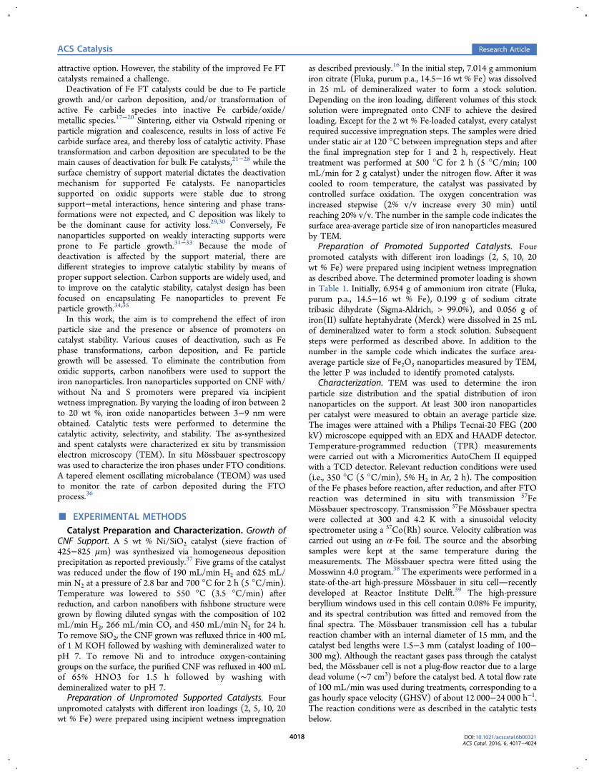
the various Fe species present during reduction and FTOconditions. Upon reduction, 25 mol % Fe carbide species weremeasured for both 4FeP and 4Fe (Figures 2a,c and SI 4). It isthus suggested that the addition of promoters did not have asignificant influence on the reduction step. This observationwas confirmed by the similar TPR profiles obtained for 4PFeand 4Fe (Figure S10). To further investigate the reductionbehavior of a promoted catalyst (7PFe), Mossbauer spectrawere measured after 2 and 24 h reduction (Ar/H2 = 2, 350 °C,2 bar). Despite the longer reduction duration, incompletereduction was observed and similar content of Fe carbide phasewas measured (Table S8 and Figure S11). However, after 20 hof FTO conditions, 4FeP was fully carburized and 4Fe had only23 mol % Fe carbide species (Figures 2b,d and SI 4). Theremaining Fe atoms were present as Fe2+ species havingMossbauer spectra similar to those of Wustite and itsnonstoichiometric equivalent (Fe1−xO).41 The promotersinduced formation of more Fe carbide species in the initialperiod, which gave higher catalytic activity. Alkali promoterssuch as Na are known to increase Fe carburization rate,42 butthe addition of S showed the opposite effect.43 It is noted that4FeP had four times more Fe carbide species, but its catalyticactivity was only twice higher than 4Fe.Carbon deposition over time was monitored in situ using the
TEOM. No carbon deposition was measured during 4 h for theunpromoted catalysts with different particle sizes (Figure S12),and it is proposed to be due to the lack of active χ-Fe5C2 phase.This proposal was supported by in situ Mossbauer spectroscopy
Table 1. Properties of As-Synthesized Promoted andUnpromoted CNF-Supported Fe Catalysts
wt % loadinga average particle size (nm)
Fe Na S Fe2O3b
3Fe 2 0.03 <0.005 34Fe 5 0.03 <0.006 47Fe 9 0.02 <0.004 79Fe 15 0.03 0.007 93FeP 2 0.10 0.02 34FeP 5 0.24 0.04 47FeP 9 0.41 0.07 79FeP 16 0.68 0.11 9
awt % loading determined using ICP-AES. bSurface area averagedetermined by TEM.
ACS Catalysis Research Article
DOI: 10.1021/acscatal.6b00321ACS Catal. 2016, 6, 4017−4024
4019

data (Figure 2) and catalyst performance data. The promotedcatalysts showed carbon accumulation over time (Figure S13).During the early stages (first 30 min approximately), there weretwo opposite occurrences for mass changes which resulted in anegligible net mass change. Further reduction of Fe oxidespecies to Fe carbide species caused a decrease in mass, whilecarbon laydown due to the Fe carbide species already presentafter reduction caused an increase in mass. Thus, the net effectwas a lower mass change rate than when the catalyst reached astate where no further reduction took place. Subsequently, thecoking rate decreased over 4 h. It is believed that the measuredmass change was caused directly by carbon build-up and nothydrocarbons because of the reaction conditions used.36
Carbon laydown rate decreased with increasing particle sizeinitially (1st hour), but the rate increased with increasing initialparticle size at steady state (4th hour). This indicates that theeffect of particle size on carbon deposition rate was differentwhen the surfaces were relatively clean and after reaction hadproceeded for a longer period. Possible reasons for this
decrease in coking rate include blocking of active sites (surfacecovered with amorphous or graphitic carbon), growth of Fecarbide particles, and phase transformations that do not convertCO to carbon. Thus, it appeared that the carbon deposition wasmost severe in the initial period and was not the main reasonfor deactivation over a longer period (10−100 h TOS).The spent catalysts after carbon deposition studies (TOS = 4
h) and after catalytic tests (TOS = 100 h) were characterizedwith TEM, and images are shown in Figure S2 and Figure 3respectively. It was mentioned earlier that the addition ofpromoters did not lead to a significant change in Fe particle sizedistribution of the fresh catalysts. However, the Fe particle sizedistributions of spent promoted and unpromoted catalysts werestrikingly different. The promoted catalysts displayed a higherdegree of sintering compared to the unpromoted catalysts. Inthe extreme case (9FeP) depicted in Figure 3h, Fe particles ofapproximately 100 nm were observed. In addition, thepromoted Fe nanoparticles seemed to have a core−shellstructure (Figure 3e−h). TEM-EDX maps (Figure 3i−m)
Table 2. Catalytic Performance of CNF-Supported Fe Catalysts under FTO Conditionsa
product selectivity (% Cat, CO2 free)
CO conv. (%) FTY (10−3 molCO/gFe·s) CO2 sel. (%) CH4 C2−C4 olefins C2−C4 paraffins C5+
3Fe 4 0.8 12 52 26 22 04Fe 3 0.3 18 50 26 24 17Fe 4 0.2 20 47 28 22 39Fe 4 0.1 23 46 36 14 43FeP 7 1.7 35 20 54 14 124FeP 7 0.7 38 11 61 6 227FeP 10 0.5 40 8 60 6 259FeP 16 0.3 42 8 60 5 27
aConditions: 340 °C, 20 bar, H2/CO/He = 45/45/10, GHSV = 54 000 h−1, TOS = 12 h.
Table 3. Catalytic Performance of CNF-Supported Fe Catalysts under FTO Conditionsa
product selectivity (% Cat, CO2 free)
CO conv. (%) FTY (10−3 molCO/gFe·s) CO2 sel. (%) CH4 C2−C4 olefins C2−C4 paraffins C5+
3Fe 6 1.3 15 49 25 21 54Fe 8 0.7 21 40 31 20 97Fe 13 0.5 30 38 36 14 129Fe 18 0.4 33 35 36 15 143FeP 2 0.8 33 14 72 7 74FeP 4 0.3 37 11 66 7 167FeP 7 0.3 41 10 62 6 229FeP 8 0.2 40 9 62 5 24
aConditions: 340 °C, 20 bar, H2/CO/He = 45/45/10, GHSV = 54 000 h−1, TOS = 100 h.
Figure 1. Iron time yield (FTY) of (a) unpromoted catalysts and (b) promoted catalysts (340 °C, 20 bar, H2/CO/He = 45/45/10, and GHSV = 54000 h−1).
ACS Catalysis Research Article
DOI: 10.1021/acscatal.6b00321ACS Catal. 2016, 6, 4017−4024
4020
showed that the core was rich in Fe and the shell was mainly Feoxide. The formation of Fe oxide was most likely due toexposure to air after reaction.In Figure 4, the average iron particle sizes of fresh and spent
catalysts are compared. The particle size distributions of spentcatalysts can be found in SI 1. It was thus shown that thepromoted Fe nanoparticles produced more carbon anddisplayed more sintering while the unpromoted catalystsshowed limited sintering even after 100 h TOS.Figure 5 reveals the effects of the particle size on the stability
of unpromoted Fe FT catalysts. The unpromoted catalystsshowed increased catalytic activity and limited sintering overtime, and it is proposed tentatively that the increased catalyticactivity is related to increased Fe carbidization.Figure 6 depicts the effects of the particle size on the stability
of promoted Fe FT catalysts. The decrease in catalytic activity
appeared to be in agreement with the increase in Fe particlesize over time. The loss of surface area per gram Fe follows therelation: surface area/volume α 1/Fe particle diameter; thus,FTY was fitted to be inversely proportional to particle size(trend line in Figure 6). The first data point (smallest averageparticle size) appeared to be an anomaly, and that is attributedto the presence of small particles around 3 and 4 nm. Thesesmall Fe particles were shown previously to be highly active andproduced mainly methane.16
For the promoted catalysts, Fe particle growth wasconcluded to be the main cause of deactivation. Phasetransformations, which occurred when water was producedbut not removed from the catalyst bed, were reportedpreviously to be a reason for deactivation;25−27 however, it isnot expected to be relevant here because of the use of highspace velocities and low conversion conditions. Carbondeposition rates decreased over the initial hours and were notexpected to play a significant role over a longer period. The useof sulfur, in the absence of sodium, to increase the resistanceagainst carbon deposition was demonstrated earlier,29 and thismay be a possibility to explain the relatively low carbondeposition rates when compared to other Fe-based catalysts.The sintering of Fe nanoparticles supported on O-function-alized CNTs was concluded previously to be more severe dueto weak support−metal interactions and a low concentration ofsurface defects for anchoring of Fe nanoparticles.33 Although aweakly interacting support CNF was used in this study, verydifferent extent of particle growth was observed for thepromoted and unpromoted Fe nanoparticles. This proves thatthe severe sintering of promoted Fe nanoparticles was notsolely due to weak metal−support interaction. Intrinsically, theFTO process would be a high temperature FT route, thussintering is expected to be more prominent than at the lesssevere conditions of low-temperature FT, which is typical forcoal-to-liquids (CTL).
■ CONCLUSIONThe activity, product selectivity and stability of CNF-supportedFe catalysts under industrially relevant Fischer−Tropsch toolefins (FTO) conditions were investigated. It was observedthat the activity of unpromoted catalysts increased over time,regardless of particle size. With addition of promoters,maximum activity was attained in the initial period anddeactivation was prominent.In situ Mossbauer spectroscopy revealed that both promoted
and unpromoted catalysts attained similar Fe carbidizationlevels after reduction. However, after 20 h of synthesis gastreatment, the promoted catalyst was fully carbided, and thecarbidization level of the unpromoted catalyst did not increasebeyond 25%. This difference in phase transformation uponexposure to synthesis gas resulted in a higher initial activity ofthe promoted catalyst. As the correlation of activity and Fecarbide species was not linear, deactivation via carbondeposition and/or Fe particle growth is proposed to occursimultaneously with phase transformations.A tapered element oscillating microbalance (TEOM) was
utilized to measure the rate of carbon deposition underindustrially relevant FTO conditions. No carbon laydown wasdetected for the unpromoted catalysts, and this was rationalizedby the lack of active Fe carbide phases. In contrast, the presenceof promoters facilitated Fe activation which resulted insignificant carbon deposition over the first hours of operation.While different particle sizes resulted in different coking rates,
Figure 2. In situ Mossbauer spectra of (a) 4Fe after reduction, (b) 4Feafter 20 h TOS, (c) 4FeP after reduction, and (d) 4FeP after 20 hTOS. Reduction: 350 °C, 2 bar, Ar/H2 = 2, 2 h. FTO: 340 °C, 20 bar,H2/CO = 1, TOS = 20 h. (3 Fe sites for Hagg carbide: magenta, red,and purple; 1 Fe site for ε′ carbide: dark cyan; 3−4 Fe sites forFe1−xO: violet, olive, navy, blue).
ACS Catalysis Research Article
DOI: 10.1021/acscatal.6b00321ACS Catal. 2016, 6, 4017−4024
4021

coking rates decreased over time. This suggests that carbondeposition is not the leading cause of deactivation over longerperiods.Limited sintering was observed for the unpromoted catalysts
while severe sintering was seen for the promoted catalysts. Thisindicated that the promoters led to formation of mobile andactive Fe phases which resulted in a higher degree of particlegrowth.For the unpromoted catalysts, phase transformation was
considered to be the leading cause for the increase in catalyticactivity over time. For the promoted catalysts, catalytic activitywas shown to be inversely proportional to Fe particle diameterof spent catalysts which leads to the conclusion that here Feparticle growth is the main reason for deactivation over time.
In this work, the catalytic performance of CNF-supported Fecatalysts under industrially relevant FTO conditions werethoroughly and critically assessed. Although the activity andC2−C4 olefins selectivity of the promoted Fe catalysts werehighly encouraging, the stability needs improvement. Carbondeposition for Fe nanoparticles was less significant compared tobulk Fe catalysts and is proposed not to play a pivotal role inthe deactivation. Sintering was, however, the major cause ofdeactivation, and it is hence believed that sintering is a vitalfactor affecting stability of these highly active and selectivepromoted Fe catalysts. Thus, the direction of future research ison designing highly active and selective Fe catalysts which aremore resistant to sintering. It is of interest for future studies to
Figure 3. TEM images of spent (a−d) unpromoted catalysts and (e−h) promoted catalysts after carbon deposition studies (340 °C, 20 bar, H2/CO= 1, GHSV = 54 000 h−1, TOS = 100 h). TEM-EDX maps of spent 7FeP catalyst (i−m).
Figure 4. Iron particle size of (blue-outline ◇) promoted catalysts and(red-outline □) unpromoted catalysts after carbon deposition studies,TOS = 4 h. Iron particle size of (blue ◆) promoted catalysts and (red■) unpromoted catalysts after catalytic tests, TOS = 100 h (340 °C,20 bar, H2/CO = 1, GHSV = 54 000 h−1).
Figure 5. Catalytic activity as a function of average iron particle size ofspent unpromoted catalysts (red-outline □) at the initial period, TOS= 4−10 h, and (red ■) at steady state, TOS = 100 h (340 °C, 20 bar,H2/CO = 1, GHSV = 54 000 h−1). Lines were added to guide the eye.
ACS Catalysis Research Article
DOI: 10.1021/acscatal.6b00321ACS Catal. 2016, 6, 4017−4024
4022

unravel the mechanism and details of particle growth ofpromoted and unpromoted Fe nanoparticles.
■ ASSOCIATED CONTENT*S Supporting InformationThe Supporting Information is available free of charge on theACS Publications website at DOI: 10.1021/acscatal.6b00321.
TEM characterization of fresh and spent catalysts,catalytic performance, in situ Mossbauer spectroscopy,and in situ carbon deposition studies (TEOM) (PDF)
■ AUTHOR INFORMATIONCorresponding Author*E-mail: [email protected] Address∥(T.G.) Albemarle Catalysts Company B.V., Nieuwendammer-kade 1−3, 1022 AB, AmsterdamNotesThe authors declare no competing financial interest.
■ ACKNOWLEDGMENTSThis research received funding from The NetherlandsOrganisation for Scientific Research (NWO) in the frameworkof the TASC Technology Area “Syngas, a Switch to FlexibleNew Feedstock for the Chemical Industry (TA-Syngas)”. Dowand Johnson Matthey are also acknowledged for the fundingreceived. K.P.d.-J. acknowledges the European ResearchCouncil, EU FP7 ERC Advanced Grant no. 338846. H.Meeldijk and W. Lamme are thanked for the TEM images.Peter Bramwell is acknowledged for the TPR measurements. H.C. de Waard is acknowledged for the ICP-AES measurements.G. Bonte (Dow Benelux) is thanked for catalyst performancetesting. M. Watson and L. van de Water (Johnson Matthey) areacknowledged for fruitful discussion.
■ REFERENCES(1) van Santen, R. A. Acc. Chem. Res. 2009, 42, 57−66.(2) Wender, I. Fuel Process. Technol. 1996, 48, 189−297.(3) Dry, M. E. Catal. Today 2002, 71, 227−241.(4) van Steen, E.; Claeys, M. Chem. Eng. Technol. 2008, 31, 655−666.(5) Zhang, Q.; Kang, J.; Wang, Y. ChemCatChem 2010, 2, 1030−1058.(6) Davis, B. H. Catal. Today 2003, 84, 83−98.
(7) Li, S.; Krishnamoorthy, S.; Li, A.; Meitzner, G. D.; Iglesia, E. J.Catal. 2002, 206, 202−217.(8) Torres Galvis, H. M.; de Jong, K. P. ACS Catal. 2013, 3, 2130−2149.(9) Khodakov, A. Y.; Chu, W.; Fongarland, P. Chem. Rev. 2007, 107,1692−1744.(10) Shroff, M. D.; Kalakkad, D. S.; Coulter, K. E.; Kohler, S. D.;Harrington, M. S.; Jackson, N. B.; Sault, A. G.; Datye, A. K. J. Catal.1995, 156, 185−207.(11) Yang, Y.; Xiang, H.-W.; Tian, L.; Wang, H.; Zhang, C.-H.; Tao,Z.-C.; Xu, Y.-Y.; Zhong, B.; Li, Y.-W. Appl. Catal., A 2005, 284, 105−122.(12) Torres Galvis, H. M.; Bitter, J. H.; Khare, C. B.; Ruitenbeek, M.;Dugulan, A. I.; de Jong, K. P. Science 2012, 335, 835−838.(13) Bahome, M. C.; Jewell, L. L.; Hildebrandt, D.; Glasser, D.;Coville, N. J. Appl. Catal., A 2005, 287, 60−67.(14) Moussa, S. O.; Panchakarla, L. S.; Ho, M. Q.; El-shall, M. S. ACSCatal. 2014, 4, 535−545.(15) Keyvanloo, K.; Mardkhe, M. K.; Alam, T. M.; Bartholomew, C.H.; Woodfield, B. F.; Hecker, W. C. ACS Catal. 2014, 4, 1071−1077.(16) Torres Galvis, H. M.; Bitter, J. H.; Davidian, T.; Ruitenbeek, M.;Dugulan, A. I.; de Jong, K. P. J. Am. Chem. Soc. 2012, 134, 16207−16215.(17) Bartholomew, C. H. Appl. Catal., A 2001, 212, 17−60.(18) Moulijn, J. A.; van Diepen, A. E.; Kapteijn, F. Appl. Catal., A2001, 212, 3−16.(19) de Smit, E.; Weckhuysen, B. M. Chem. Soc. Rev. 2008, 37, 2758−2781.(20) de Smit, E.; Cinquini, F.; Beale, A. M.; Safonova, O. V.; vanBeek, W.; Sautet, P.; Weckhuysen, B. M. J. Am. Chem. Soc. 2010, 132,14928−14941.(21) Niemantsverdriet, J. W.; van der Kraan, A. M. J. Catal. 1981, 72,385−388.(22) Eliason, S. A.; Bartholomew, C. H. Appl. Catal., A 1999, 186,229−243.(23) Nakhaei Pour, A.; Housaindokht, M. R.; Zarkesh, J.; Tayyari, S.F. J. Ind. Eng. Chem. 2010, 16, 1025−1032.(24) Pendyala, V. R. R.; Graham, U. M.; Jacobs, G.; Hamdeh, H. H.;Davis, B. H. ChemCatChem 2014, 6, 1952−1960.(25) Pendyala, V. R. R.; Graham, U. M.; Jacobs, G.; Hamdeh, H. H.;Davis, B. H. Catal. Lett. 2014, 144, 1704−1716.(26) Ning, W.; Koizumi, N.; Chang, H.; Mochizuki, T.; Itoh, T.;Yamada, M. Appl. Catal., A 2006, 312, 35−44.(27) Li, S.; O'Brien, R. J.; Meitzner, G. D.; Hamdeh, H.; Davis, B. H.;Iglesia, E. Appl. Catal., A 2001, 219, 215−222.(28) Niemantsverdriet, J. W.; van der Kraan, A. M.; van Dijk, W. L.;van der Baan, H. S. J. Phys. Chem. 1980, 84, 3363−3370.(29) Zhou, X.; Ji, J.; Wang, D.; Duan, X.; Qian, G.; Chen, D.; Zhou,X. Chem. Commun. 2015, 51, 8853−8856.(30) Galuszka, J.; Sano, T.; Sawicki, J. A. J. Catal. 1992, 136, 96−109.(31) Abbaslou, R. M. M.; Tavasoli, A.; Dalai, A. K. Appl. Catal., A2009, 355, 33−41.(32) Abbaslou, R. M. M.; Tavassoli, A.; Soltan, J.; Dalai, A. K. Appl.Catal., A 2009, 367, 47−52.(33) Schulte, H. J.; Graf, B.; Xia, W.; Muhler, M. ChemCatChem2012, 4, 350−355.(34) Yu, G.; Sun, B.; Pei, Y.; Xie, S.; Yan, S.; Qiao, M.; Fan, K.;Zhang, X.; Zong, B. J. Am. Chem. Soc. 2010, 132, 935−937.(35) Santos, V. P.; Wezendonk, T. a.; Jaen, J. J. D.; Dugulan, a. I.;Nasalevich, M. a.; Islam, H.-U.; Chojecki, A.; Sartipi, S.; Sun, X.;Hakeem, A. a.; Koeken, A. C. J.; Ruitenbeek, M.; Davidian, T.; Meima,G. R.; Sankar, G.; Kapteijn, F.; Makkee, M.; Gascon, J. Nat. Commun.2015, 6, 6451.(36) Koeken, A. C. J.; Torres Galvis, H. M.; Davidian, T.;Ruitenbeek, M.; de Jong, K. P. Angew. Chem., Int. Ed. 2012, 51,7190−7193.(37) van der Lee, M. K.; van Dillen, A. J.; Geus, J. W.; de Jong, K. P.;Bitter, J. H. Carbon 2006, 44, 629−637.
Figure 6. Catalytic activity as a function of average iron particle size ofspent promoted catalysts (blue-outline ◇) at the initial period, TOS =4−10 h, and (blue ◆) at TOS = 100 h (340 °C, 20 bar, H2/CO = 1,GHSV = 54 000 h−1). The trend line is fitted to y α x−1 for all datapoints except the first point.
ACS Catalysis Research Article
DOI: 10.1021/acscatal.6b00321ACS Catal. 2016, 6, 4017−4024
4023

(38) Klencsar, Z. Nucl. Instrum. Methods Phys. Res., Sect. B 1997, 129,527−533.(39) Dugulan, A. I. Final report of the ACTS-programme ASPECT;The Netherlands Organisation for Scientific Research: The Hague,Netherlands, 2012.(40) Shibata, H.; McAdon, M.; Schroden, R.; Meima, G.; Chojecki,A.; Catry, P.; Bardin, B. In Modern Applications of High ThroughputR&D in Heterogenous Catalysis; Hagemeyer, A., Volpe, A. F., Eds.;Bentham Science Publishers: United Arab Emirates, 2014; Vol. 48, pp173−196.(41) Schweika, W.; Hoser, A.; Martin, M.; Carlsson, A. E. Phys. Rev.B: Condens. Matter Mater. Phys. 1995, 51, 15771−15788.(42) Ribeiro, M. C.; Jacobs, G.; Davis, B. H.; Cronauer, D. C.; Kropf,A. J.; Marshall, C. L. J. Phys. Chem. C 2010, 114, 7895−7903.(43) Xu, J.; Chang, Z.; Zhu, K.; Weng, X.; Weng, W.; Zheng, Y.;Huang, C.; Wan, H. Appl. Catal., A 2016, 514, 103−113.
ACS Catalysis Research Article
DOI: 10.1021/acscatal.6b00321ACS Catal. 2016, 6, 4017−4024
4024