Embed Size (px)
Citation preview
Szybkobie�ne Pojazdy G�sienicowe (41) nr 3, 2016
Dr Zbigniew KAMYK, Cezary �LIWI�SKI, Krzysztof DUDEK, Dr Piotr KRYSIAK – Military Institute of Engineer Technology, Wrocław
Zbigniew KAMYK Cezary �LIWI�SKI Krzysztof DUDEK Piotr KRYSIAK
CONCEPT OF A MODULAR FOOTBRIDGE TO BE USED IN CRISIS SITUATIONS
Abstract. Increasing occurrence of natural disasters requires the use of such equipment which would enable either rapid evacuation, or quick restoration of pedestrian infrastructure with the mainland. The existing infantry footbridges, however, do not fulfil the civilian standards of safety of use. The paper presents a concept and tests of a light modular footbridge for pedestrian use in crisis situations. This footbridge would be used to cross obstacles up to 20 m wide. Optimisation of the construction in terms of shape, mechanical strength, weight enabled the development of modules which guarantee easy transport and assembly. The assembly is simple; it can be done by a small group of people without the need for special equipment or machinery and requiring only minimum amount of supervision. Modularity of the structure allows the users to adapt it to various terrain conditions with ease. Furthermore, the modular footbridge can be adjusted so as to accommodate the new requirements issued by the crisis services, as far as functionality is concerned – both the length and width of the footbridge can be altered.
Keywords: footbridge, in situ load test, crisis situations.
1. INTRODUCTION
Military bridging equipment, apart from typical military use, can also be used during peacetime in crisis situations to build provisional bridges (road failures and collapses) or in other states of necessity (repairs or reconstruction of permanent bridges). Today, however, the Polish Armed Forces do not have lightweight modular structures allowing rapid construction of footbridges and small bridges for local traffic���
Engineer troops are particularly in the position to provide help in the area of transport infrastructure reconstruction, hence the formation of Military Reconstruction Units (WJO) [1]. Their basic equipment used to reconstitute bridges are foldable bridges of the DMS-65 type. These bridges are already quite exhausted, too narrow for military use, and are not mobile enough and too heavy to use in crisis situations.
Restoration of local and regional traffic in the area of a flood is always a priority for the authorities and rescuers. Floods that have occurred in recent years in Poland [2-4] and in other parts of the world [5-6] always caused a lot of damage in the transport infrastructure. Floods are most common in mountainous regions [2] where, due to the nature of the terrain, there are numerous small rivers and streams that impede access of inhabitants to the outside world. In such cases many small bridges and footbridges are needed to re-establish normal existence of the inhabitants of the region hit by the crisis. In 1997 about 170 bridges were destroyed in the small area of the Kłodzko Basin [2].
It is advisable, therefore, that modern crisis management system has the capabilities, in the form of procedures and material resources, to protect vulnerable areas against floods, especially in the form of means for evacuating the threatened areas and for restoring traffic. The army has at its disposal bridges which are perfectly suited for the reconstruction of road infrastructure in areas struck by floods. This has been proven by experiences of recent years

78 79Zbigniew KAMYK, Cezary �LIWI�SKI, Krzysztof DUDEK Piotr KRYSIAK
�
which were described in the literature [2-4]. Some of the foldable bridges may be used not only for the construction of alternative crossings in place of damaged, destroyed or repaired permanent bridges, but also for the construction of footbridges. One such example is the footbridge over the road in the town of Walim (Fig. 1). That footbridge was constructed using components of an MS-22-80 foldable bridge. That structure, however, has been "demilitarised" and is now a private property. In addition, it is a relatively heavy structure, requires logistic support and specialist handling. The DMS-65 bridge is also not suited for constructing a lightweight footbridge. WJO often construct footbridges made of wood (Fig. 2) or of wood and steel. These are labour-intensive and require intermediate supports. There is, therefore, a gap in the capabilities to quickly build footbridges that in areas struck by floods would constitute an alternative to the use of boats or amphibians for rescuing people. Afterwards they could be used to maintain contingence with the surroundings, until the construction of larger temporary or permanent bridges is completed.
Fig. 1. Examples of temporary footbridges left - an MS 2280 structure [7], right - construction of a wooden footbridge [8]
Such footbridges should have a modular structure that allows constructing bridges of various spans within 10 to 30 metres. Spans of ca. 20 m ensure crossing most (ca. 80%) terrain obstacles encountered in Poland. The structure should be light enough and easy to transport to enable its manual installation.
Currently, the Polish Army and the rescue services do not have such a structure, and the standard structures of military footbridges in other countries are not suitable for use by civilians, except for short-term emergency situations. "Military footbridges", usually called assault footbridges, are designed for the infantry to carry out hidden attacks in a difficult area.
Fig. 2. Military assault footbridges: German LAB [9], Indian MFB [10]

78 79Concept of a modular footbridge to be used in crisis situations
�
Among the armies of the world the two most popular assault footbridges include the Israel's Sectional Personnel Bridge (SPB) [11] and Germany's (Fig. 2) Infantry Assault Bridge (IAB) [9]. Because of the width of the deck and low handrails, these footbridges are designed specifically for military use. Specifications of the footbridges, compared to the new WITI concept, are presented in Table 1. Recently, in India, based on experience with a lightweight military footbridge for mountain areas (Mountain Footbridge - MFB, Fig. 2), its civilian version was developed for use in crisis situations. The aluminium MFB footbridge is designed for negotiating obstacles up to 35 m wide and has a deck 0.8 m wide, while its civilian version is made of steel, is wider (1.5 m wide deck), and shorter, with a maximum span of 13.5 m.
Table 1. Specifications of footbridges for pedestrians [15]
Parameter Type
WITI IAB SPB Weight of single module 80 kg 55.5 kg 42 kg Weight of two-segment footbridge 160 kg – – Weight of three-segment footbridge 240 kg – – Weight of footbridge of maximum length
320 kg 480 kg 380 kg
Length of single module 5575 mm 4430 mm 4000 mm Maximum length of footbridge 22300 mm 30000 mm 36000 mm Width 800 mm 660 mm 660 mm Height 1145 mm 710 mm 710 mm Footbridge capacity 16
people/min. 8 people/min. 8 people/min.
2. CRITERIA ADOPTED FOR THE DESIGN OF A FOOTBRIDGE TO BE USED IN CRISIS SITUATIONS
2.1. Requirements and concept
Based on experience gained in crisis situations and on the analysis of the design of assault footbridges, an assumption was made that the footbridge for use in crisis situations should enable crossing obstacles with a width of about 20 m. The structure should be as light as possible to enable handling by the crew. It is necessary to enable provision of pedestrian crossings over water and terrain obstacles in places where there often is no direct access to transport means. The width and carrying capacity of the bridge should allow crossing the bridge by people and wheelchairs.
Functional requirements and strength are usually specified by the project developer in compliance with applicable standards. Currently there are no standard requirements specifying the width of the bridge deck for crisis footbridges. Permissible load for footbridges can be adopted from a civilian standard [12] or from military guidelines [13].
80 81Zbigniew KAMYK, Cezary �LIWI�SKI, Krzysztof DUDEK Piotr KRYSIAK
�
�
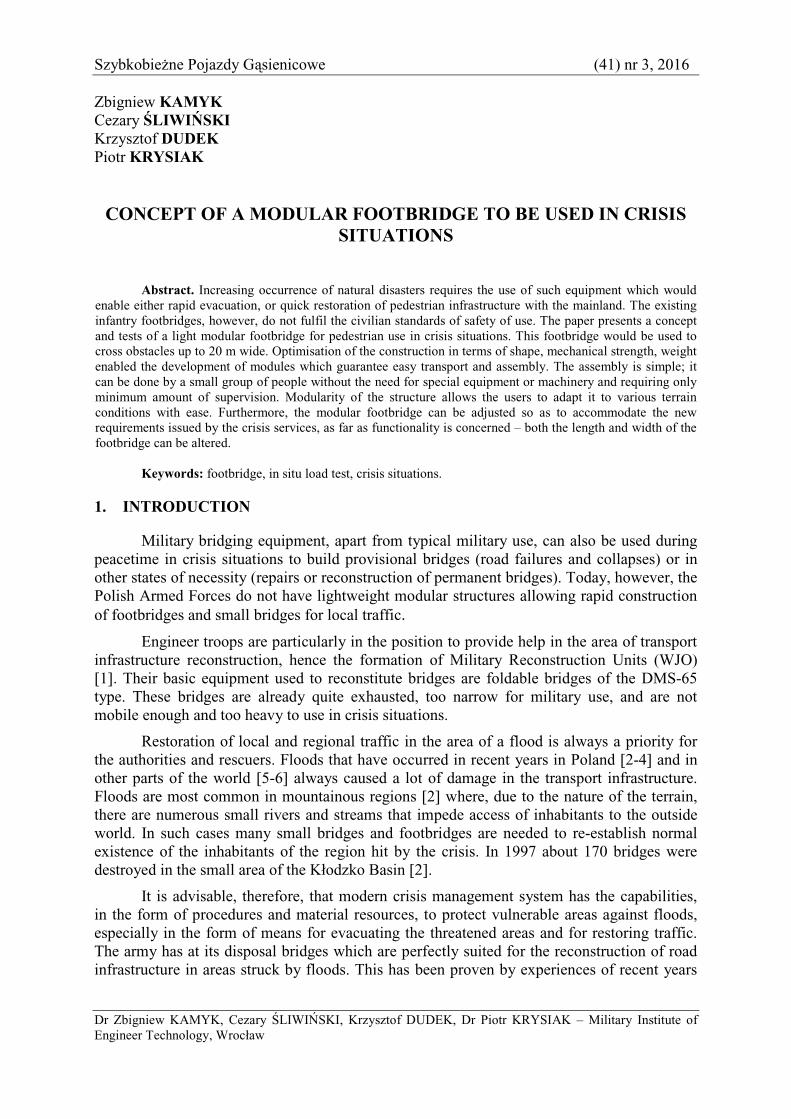
Fig. 3. View of the footbridge module and layout of its segments in ISO 1CC transport container [15]
According to military guidelines [13], a footbridge for pedestrians should be at least 650 mm wide. Whereas the Ordinance of the Minister of Transport and Maritime Economy of 30.05.2000 [14] does not specify the width of the footbridges, but it indicates that the height of the barrier along pedestrian and service walkways should be min. 1.1 m. � The minimum width of the deck enabling passage of a wheelchair was adopted at 800 mm.
The analysis carried out has indicated the need to design a footbridge with a walkway 0.8 m wide and handrails 1.1 m high, for a load generated by one centrally localized person per each module of the footbridge. That load should be 1.27 kN [15]. A "transport package" should be developed for the footbridge kit, in the form of a 20" container or a special hook lift platform allowing it to be transported and launched at the construction site by means of a vehicle operating a hook (Fig. 3).
2.2. Description of the footbridge model
Based on the conceptual work performed [15], two modules of the footbridge with a length of 5575 mm were constructed to verify theoretical calculations using a model in a scale of 1:1. Depending on the width of the obstacle, the footbridge can consist of one, two (Fig. 4), three or four modules (Table 1) connected to each other at the level of the girders and handrail by means of special couplings enabling rapid attachment or disengagement of subsequent segments. � The lower couplings use pins, upper couplings are designed as threaded systems. The modules are made of AW 6063 aluminium alloy (pipes, rectangular and square profiles) in the form of welded spatial structure. The profiles used were either butt welded together or welded with the use of gussets. The deck was covered with aluminium checker plates provided with holes for draining rainwater. The footbridge, depending on the number of modules used, enables setting up a span 22 m, 16 m, 11 m or 5.5 m long. When water obstacles are wider than 20 m it is possible to support subsequent footbridges on floats or on the side of a boat.

80 81Concept of a modular footbridge to be used in crisis situations
�
Fig. 4. Two-segment footbridge with a 900-kg load (Pattern 2 in Table 2) �
���ADOPTED PROGRAM OF TESTING THE FOOTBRIDGE FOR PEDESTRIANS�
The aim of testing the model of the footbridge was to verify the correctness of the assumptions adopted for constructing footbridge modules and their connections by checking the ultimate strength and deflections. Prior to the load tests of the footbridge, a test program was developed to check the strength of bridge components under the loads occurring during the use of the footbridge of different lengths and during its erection.
Service load assumes the presence of one person on the module, therefore the obvious pattern of loading a footbridge consisting of two segments is to apply centrally to each segment a concentrated force P = 1.27 kN.
Since only two segments of the footbridge were available, an equivalent load generating an equivalent bending moment was calculated for footbridges consisting of a greater number of modules. This load included the dead weight of the segments and the forces applied P = 1.27 kN. The most unfavourable load during erection occurs when a four-segment footbridge is moved over an obstacle. An equivalent load applied to a support with its length equal to that of a single module was also determined. Table 2 lists the patterns and parameters of the equivalent loads for the purpose of strength testing of the load-bearing structure and of the bridge connections.
a)
��
Fig. 5. Diagram of a two-segment footbridge with indicated locations of strain gauges a) side view; b) bottom view
�
Basic load tests were carried out within the static range on a special test bench (Fig. 4) with the footbridge modules provided with strain gauges at points of theoretically determined greatest effort of the structure components (Fig. 5).

82 83Zbigniew KAMYK, Cezary �LIWI�SKI, Krzysztof DUDEK Piotr KRYSIAK
�
Table 2. Parameters and location of loads during the testing of the footbridge
Test no.
Load arrangement Simulated conditions
Applied load Type of load
1 step Max.
1.Load on a 2-segment bridge
2 × 150 kg
2 × 225 kg
Concentrated / load on 2 segments
2.Load on a 4-segment bridge
150 kg 900 kg Concentrated
/ load on 4 segments
3.Launching a 4-segment bridge
150 kg 900 kg
Concentrated - equivalent / weight of 4 segments
�
The footbridge was loaded with ballasts, 75 kg each, subsequently, according to the loading patterns (Table 2), with an increment of 150 kg. View of the footbridge with a 900 kg load (12 pcs., 75 kg each) is shown in Fig. 4. There was a 15-minutes period before each load increase, the total load remained for 30 minutes. In addition, a simulation of a dynamic load was conducted by registering stress during the movement of groups of pedestrians at different intervals and at different speeds���
Measurements of the stresses occurring in the structure of the footbridge were carried out using electrical resistance strain gauges and a strain gauge bridge. Measurements of vertical displacements were made using inductive sensors, and the settling of supports was monitored by means of a laser level.
���� RESULTS OF VERTICAL DISPLACEMENT AND STRESS MEASUREMENTS�
The tests of the footbridge structure have been completed successfully. No damage to structural elements of the bridge or the joints was observed under the assumed maximum service and assembly loads.
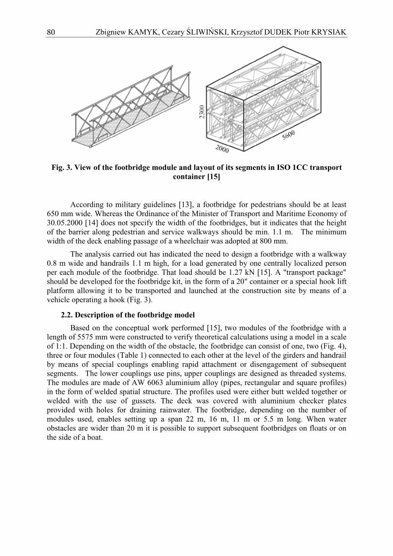
The measured deflections for the three load patterns (Fig. 8) have not exceeded the permissible values, and there was no buckling of the structural elements. Load patterns 1 and 2 correspond to operating loads, for which the values of deflection were determined. Deflections of the footbridge observed during strength testing of two-segment and four-segment footbridges under standard load were small at no more than 9.2 mm. Assuming that permissible deflection of girders is l/600 (where l is the length of the footbridge), the value for a 22-m long footbridge is 36.6 mm. The structure of the footbridge has shown high stiffness; this result, however, is subject to the error of model similarity, as the bridge span was 11 m, and in this case the permissible deflection is 18.3 mm. In addition, the actual footbridge with a span of 22 m will additionally have two bolt connections in the bottom flange of girders. Slackness of these connections will increase the deflection. However, because of the stiffness of the entire structure it should not exceed permissible values. The permament set after testing was 0.2 mm.
82 83Concept of a modular footbridge to be used in crisis situations
�
Fig. 8. Deflections of the footbridge under various loading patterns
Vertical displacement of the end of the footbridge, observed during the simulation of the process of moving the footbridge over an obstacle (3rd load pattern) is much larger than in the case of the first two patterns. The reason for this is that deflection is measured at the end of the support and a larger bending moment occurring in this cross section of the structure. For such a static pattern the rules of determining permissible girder deflections do not apply. Therefore, given the short time of erecting the footbridge, it is concluded that the deflections measured during the tests are permissible.
Throughout all of the tests the settling of the supports was also measured. No settlement of supports made of wooden logs secured with 15 mm thick steel plates has been observed during the tests.

84 85Zbigniew KAMYK, Cezary �LIWI�SKI, Krzysztof DUDEK Piotr KRYSIAK
�
Load (kg)
Stre
ss (
MP
a)
Fig. 9. Distribution of stress in structural elements of the footbridge at various load levels (Pattern 2 Table 2)
Maximum stresses in the structural elements of the footbridge measured during the tests for all three load patterns (Figs. 9 and 10) did not exceed 70 MPa. The greatest effort of the structure was generated under the erection load pattern (Fig. 10). The stresses in this case were three times higher than the maximum operational load (Fig. 9). The greatest stresses occurred in the lower flange of the structure (tens. 3 and 5) and in the upper flange - handrail (tens. 14 and 15). � � The state of the structure, compression – tension, was accordant with the static pattern of the specific load.
Stre
ss (
MP
a)
Load (kg)
Fig. 10. Distribution of stress in structural elements of the footbridge as a function of load recorded during the simulation of the construction of a four-segment footbridge
over an obstacle (Pattern 3 Table 2)
The dynamic loading test of the structure showed no significant increase in stress (Fig. 11), except for an angle brace between the bottom flanges (tens. 8). � Due to the length of the footbridge, two segments, there were two people at the same time on the footbridge, which resulted in a slight response of the bottom flange being an essential supporting element. The dynamics of the structure will be the subject of another study.

84 85Concept of a modular footbridge to be used in crisis situations
�
The measured values of stress and vertical displacements warrant full strength and stability under the assumed load conditions. Stress values are small compared to the yield strength of the footbridge construction material, which in the case of the 6063 AW aluminium alloy is 150 MPa. Accordingly, the most stressed element of the footbridge structure under the most unfavourable load is characterised by a safety factor of 2.15. This indicates that the footbridge has adequate strength to ensure its safe erection and operation. It is also possible to extend the footbridge set with one segment to a total length of 27.5 m.
�Fig. 11. Changes in stresses in the footbridge elements during dynamic testing
comprising running over the footbridge of 4 people with a distance between these people equal to the length of one segment of the footbridge
5. CONCLUSIONS
The analyzes carried out have shown that truss footbridges made of cold-formed aluminium hollow sections may be an interesting option for spans ranging from 20 to 45 m. Such footbridges are resistant to wear and have satisfactory rigidity. Low construction cost and high durability of aluminium structures make the proposed modular footbridges an attractive solution for crisis situation requirements.
Modular structure of the footbridge allows its erection in four various configurations adapted to the width of obstacles and terrain configuration. The splitting of the footbridge into modules, with each module being lightweight, allows manual transport in the area of difficult access.
At present the Military Reconstruction Units are the only and most mobile "undertakings" ready to render prompt assistance in the reconstruction of road infrastructure. However, they do not have the right equipment for the construction of footbridges. Reconstruction or restoration of traffic across minor water obstacles does not require the involvement of large human resources and heavy equipment. The modular structure of a footbridge proposed in the paper, along with its transport system, can fill the gap in responding to crisis situations, not only in the military, but also in the crisis management system.
The footbridge set can be included in the service of selected State Fire Brigades and can be transferred to the crisis site by means of regular means of transport. Assembly of the
Time [sec]
Stre
ss [M
Pa]

86 87Zbigniew KAMYK, Cezary �LIWI�SKI, Krzysztof DUDEK Piotr KRYSIAK
�
footbridge is simple and can be carried out manually by local people under the supervision of instructors.
The footbridge can be designed with a span and deck width as specified by the project developer.
At a later stage the use of composite materials [16] for the construction of the footbridge should be considered and elements of the assembly system should be developed. The use of composites necessitates the development and fabrication of composite profiles for special purposes [17].
6. REFERENCES
[1] B�benek B.: Wyzwania in�ynierii wojskowej. Przegl�d Sił Zbrojnych Nr 2/2014, pp. 8-12.
[2] Ciszewski T., Kamyk Z., Ma�ko Z.: Zniszczenia dróg i obiektów mostowych w Kotlinie Kłodzkiej w wyniku fali powodziowej. In�ynieria i Budownictwo 1/1998, pp. 16-19.
[3] Kowalkowski S.: U�ycie wojsk in�ynieryjnych podczas powodzi. PWL 2008/04, pp. 2-25.
[4] Zamiar Z., Ciszewski T., Kamyk Z.: Bridge Reconstruction: Polish Engineers Provide Assistance After 1000 Years Flood, Engineer, The Professional Bulletin For Army Engineers, Vol. 29 August 1999, pp. 11-15.
[5] Ma�as P.,Sobotková Š.: Using of temporary bridges after floods in Czech Republic. Konferencja Naukowo-techniczna „In�ynieria wojskowa - współdziałanie z układem pozamilitarnym w sytuacjach kryzysowych”. Szklarska Por�ba 24-25 kwietnia 2003 r., Zeszyty naukowe WSOWL Pogl�dy i Do�wiadczenia 2003 r. nr spec., pp. 255-258.
[6] Hays W.: Remembering 2010’s Floods, [on line] http://www.bibalex.org/ supercourse/PPT/40481.htm, [access: 06.06.2016].
[7] Bartnicki A., Drozdowska K.: Utrzymanie zniszczonych przepraw stałych z wykorzystaniem wojskowych mostów składanych. TRANSCOMP – XIV International Conference. Computer Systems Aided Science, Industry and Transport, Logistyka 6/2010, pp. 69-78.
[8] Politowski B.: ołnierze buduj� kładk� miejsk� w aganiu, [on line] http://www.polska-zbrojna.pl/home/articleshow/16931?t=Zolnierze-buduja-kladke-miejska-w-Zaganiu, [access: 03.06.2016].
[9] Infantry Assault Bridge, materiały informacyjne firmy GDLS, [on line], https://www.gdels.com/products/bridge_1.asp?id=4, [access: 06.06.2016].
[10] Mountain foot bridge developed by DRDO deployed for public use. http://www.thehindubusinessline.com/news/mountain-foot-bridge-developed-by-drdo-deployed-for-public-use/article6225098.ece [access: 06.06.2016].
[11] Sectional Personnel Bridge [on line], http://www.imi-israel.com/home/doc.aspx?mCatID=68502. [access: 06.06.2016].
[12] PN-S-10030-1985. Obiekty mostowe. Obci��enia.
[13] Trilateral design and test code for military bridging and gap-crossing equipment agreed to by: Federal Republic of Germany, United Kingdom and United States of America published in the United States in January 2005.

86 87Concept of a modular footbridge to be used in crisis situations
�
[14] Ordinance of the Minister of Transport and Maritime Economy of 30.05.2000 on technical conditions to be met by road structures and their location (Dz. U. No. 63, item 735, as amended).
[15] Kamyk Z., Dudek K., Koncepcja modułowej kładki dla pieszych do zabezpieczenia sytuacji kryzysowych. Logistyka 5/2014, pp. 678-685.
[16] Szelka J., Kamyk Z., Kompozytowe mosty wojskowe. Budownictwo i Architektura 12(2) (2013), pp. 63-70.
[17] Krysiak P., Czulak A., Rybczy�ski R., Hufenbach W., Dobór elementu układu wieloczłonowego z materiału kompozytowego. Polimery i Kompozyty Konstrukcyjne. Logos Press, 2011, pp. 234-241.


![EDUCATION IN CRISIS SITUATIONS - Columbia Universitydsb33/Assests/BurdeEdCrisis11-11-05[2].pdf · 2006-05-22 · EDUCATION IN CRISIS SITUATIONS ... Dana Burde, Ph.D. Saltzman Institute](https://img.dokumen.tips/doc/110x75/5c9b076609d3f2404d8b4d0b/education-in-crisis-situations-columbia-dsb33assestsburdeedcrisis11-11-052pdf.jpg)