Embed Size (px)
Citation preview

SITRANS P measuring instruments for pressureFittings
Technical description
2/195Siemens FI 01 · 2010
2
■ Overview
All 21-off fittings can be secured onto walls, racks (72 mm grid) and vertical and horizontal pipes.
This offers the advantage when assembling a plant that the shut-off fittings can be secured first and the lines for the medium and differential pressure connected to them. It is then possible to check all connections for leaks and to blow out or flush the pipes in order to remove dirt (welding residues, shavings etc.).
The measuring instruments can be screwed onto the shut-off fit-tings right at the end when all piping has been completed.
If an instrument has to be removed for maintenance, the fittings and pipes remain as they are. It is only necessary to close the valves – the instrument can then be removed, and refitted follow-ing maintenance.
Classification according to pressure equipment directive (DGRL 97/23/EC):
For gases of fluid group 1 and liquids of fluid group 1; compli-ance with requirements of article 3, paragraph 3 (sound engi-neering practice).Siemens FI 01 · 2010
New standard DIN EN 61518
The flange connection between transmitter and valve manifold was modified in the new standard DIN EN 61518. The only con-nection thread approved for use in the process flanges of the pressure transmitter is 7/16-20 UNF.
The valve manifolds for M12 screws, including the accessory sets, have therefore been deleted.
Material acceptance test certificate to EN 10204-3.1
If a material acceptance test certificate to EN 10204-3.1 is re-quired when ordering valve manifolds or shut-off fittings, please note that a single certificate is sufficient for each ordered item type. This means that you will only be charged for one certificate in the cost calculations.
■ Pressure transmitters with shut-off fittings - mounting examples
SITRANS P transmitter for gauge pressure with double shut-off valve, SITRANS P pressure transmitter with multiway cock or 3-spindle valve manifold
SITRANS P transmitter for differential pressure with 3-way valve manifold, 3-spindle valve manifold or valve manifold combination DN 5/DN 8
SITRANS P pressure transmitter for differential pressure, mounted in pro-tective box (available on request)
SITRANS P pressure transmitter mounted on valve combination "Monoflange" for direct connection to flanges (available on request)
© Siemens AG 2009

SITRANS P measuring instruments for pressureFittings
Selection aid
2/196 Siemens FI 01 · 2010
2
■ Selection of available shut-off valves
Transmitters Shut-off valves for general applications
Page Shut-off valves for special applications
Page
Relative and absolute pres-sure transmitters with process connection G½" male threade.g.• SITRANS P, Z series
7MF1564-.....-.A..• SITRANS P300
7MF802.-...0.-....• SITRANS P DS III series
7MF403.-...0.-.... and7MF423.-...0.-....
Shut-off valves/double shut-off valves to DIN 16270, DIN 16271 and DIN 16272
2/198 Double shut-off valve DN 5 for crossover ½-NPT-F to G½ nipple connection7MF9011-4EA
2/201
2-spindle valve manifold DN 5 for installation in pro-tective boxes7MF9412-1B
2/218
Relative and absolute pres-sure transmitter with G½"-14 NPT female thread• e.g.• SITRANS P Z series
7MF1564-.....-.H..• SITRANS P300
7MF802.-...1.-....• SITRANS P DS III series
7MF403.-...1.-.... and 7MF423.-...1.-....
Double shut-off valve DN 57MF9011-4FA and 7MF9011-4GA
2/201 Double shut-off valve DN 5 for process connec-tion ½-NPT7MF9011-4DA
2/201
Absolute pressure transmitter with process connection to IEC 61518e.g.• SITRANS P DS III series
7MF433.-...
2-spindle valve manifold DN 57MF9411-5A.
2/203 2-spindle valve manifold DN 5 for installation in pro-tective boxes7MF9412-1C.
2/218
© Siemens AG 2009

SITRANS P measuring instruments for pressureFittings
Selection aid
2/197Siemens FI 01 · 2010
2
Differential pressure transmit-ter with process connection to IEC 61518e.g.• SITRANS P DS III series
7MF443.-... and 7MF453.-...
For 3/5-spindle valve manifold DN 57MF9411-5B. and 7MF9411-5C.
2/203 3-way valve manifolds, DN 5, forged version7MF9410-1..
2/208
5-way valve manifolds, DN 5, forged version7MF9410-3..
2/208
PN 100 multiway cocks7MF9004-...
2/2063-way valve manifolds, DN 8, forged version7MF9416-1.. and 7MF9416-2..
2/211
Valve manifold combina-tion DN 5/DN 8 for vapor measurement7MF9416-6..
2/214
Valve manifold combina-tion DN 8 for vapor mea-surement7MF9416-4..
2/216
3- and 5-spindle valve manifolds for DN 5 for installation in protective boxes7MF9412-1D. and 7MF9412-1E.
2/218
3- and 5-spindle valve manifolds for vertical dif-ferential pressure lines7MF9413-1..
2/222
Low-pressure multiway cock7MF9004-4..
2/225
Transmitters Shut-off valves for general applications
Page Shut-off valves for special applications
Page
© Siemens AG 2009

SITRANS P measuring instruments for pressureFitttings - Shut-off valves for gauge and absolute pressure transmittersShut-off valvesto DIN 16270, DIN 16271 and DIN 16272
2/198 Siemens FI 01 · 2010
2
■ Overview
Transmitter for pressure with double shut-off valve 7MF9401-...
The shut-off valves for pressure gauges are used to shut off the line of the measured medium when dealing with aggressive and non-aggressive gases, vapors and liquids.
■ Design
A water trap must be connected upstream of the shut-off valve in the case of temperatures of the medium above 120 °C. The shut-off valves form B have a shaft with which they can be se-cured on an instrument bracket. An adapter is therefore not re-quired to secure these valves. The vent/test connection can be shut off separately with the double shut-off valves DN 5. This per-mits checking of the zero on the pressure gauge. In addition, the characteristic of the pressure gauge can be checked using an external pressure source.
Instrument bracket, see page 2/202.
Selection and Ordering data Order No.
Shut-off valves, form B, DIN 16270
without test collar, connection shank, without certificate
MaterialValve housing
Maximum permissibleworking pressure
CW614N (CuZn39Pb3)(mat. No. 2.0402)
250 bar 7MF9401-7AA
P250GH(mat. No. 1.0460)
400 bar 7MF9401-7AB
X 6 CrNiMoTi 17 12 2 (mat. No. 1.4571/316Ti)
400 bar 7MF9401-7AC
Shut-off valves, form B, DIN 16271
with test collar, connection shank, without certificate
MaterialValve housing
Maximum permissibleworking pressure
CW614N (CuZn39Pb3)(mat. No. 2.0402)
250 bar 7MF9401-7BA
P250GH(mat. No. 1.0460)
400 bar 7MF9401-7BB
X 6 CrNiMoTi 17 12 2(mat. No. 1.4571/316Ti)
400 bar 7MF9401-7BC
Shut-off valves, form B, DIN 16270
without test collar, pipe union with ferrule12 S DIN EN ISO 8484-1, without certificate
MaterialValve housing
Maximum permissibleworking pressure
P250GH(mat. No. 1.0460)
400 bar 7MF9401-8AB
X 6 CrNiMoTi 17 12 2(mat. No. 1.4571/316Ti)
400 bar 7MF9401-8AC
Shut-off valves, form B, DIN 16271
with test collar, pipe union with ferrule12 S DIN EN ISO 8484-1, without certificate
MaterialValve housing
Maximum permissibleworking pressure
P250GH(mat. No. 1.0460)
400 bar 7MF9401-8BB
X 6 CrNiMoTi 17 12 2(mat. No. 1.4571/316Ti)
400 bar 7MF9401-8BC
Double shut-off valves, form B, DIN 16272
with test collar, connection shank, without certificate
MaterialValve housing
Maximum permissibleworking pressure
CW614N (CuZn39Pb3)(mat. No. 2.0402)
250 bar 7MF9401-7DA
P250GH(mat. No. 1.0460)
400 bar 7MF9401-7DB
X 6 CrNiMoTi 17 12 2(mat. No. 1.4571/316Ti)
400 bar 7MF9401-7DC
Double shut-off valves, form B, DIN 16272
with test collar, pipe union with ferrule12 S DIN EN ISO 8484-1, without certificate
MaterialValve housing
Maximum permissibleworking pressure
P250GH(mat. No. 1.0460)
400 bar 7MF9401-8DB
X 6 CrNiMoTi 17 12 2(mat. No. 1.4571/316Ti)
400 bar 7MF9401-8DC
Accessories
Factory test certificate EN 10204–2.2 7MF9000-8AB
Material acceptance test certificate EN 10204-3.1
7MF9000-8AD
Selection and Ordering data Order No.
© Siemens AG 2009
SITRANS P measuring instruments for pressureFitttings - Shut-off valves for gauge and absolute pressure transmitters
Shut-off valvesto DIN 16270, DIN 16271 and DIN 16272
2/199Siemens FI 01 · 2010
2
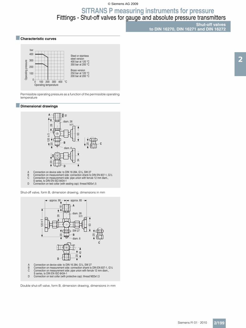
■ Characteristic curves
Permissible operating pressure as a function of the permissible operating temperature
■ Dimensional drawings
Shut-off valve, form B, dimension drawing, dimensions in mm
Double shut-off valve, form B, dimension drawing, dimensions in mm
�
���
���
���
������
� ��� ��� ��� ���
��
��������� ����
�� �������� �� �����
�� ����������� ���� ��� �����������������������������������
������� �����������������������������������
��
������
����
��
���
�
� �� �
��
��
�
���!��
���!���
" ��� #�������� ��# ��� $����%&'�������(�)*(��+��,� ��� #��������� ���� � ����� $�#��� #���������-����%&'�.'���,/�(�)* ��� #��������� ���� � ����� $���� �������0����1 ���� ������� ���!(
��� �� �(����%&'�.'�&�������/�% ��� #��������� ���#������20����� ������#��3$���� � �4��5�(�
��
������
����
��
���
����
�+��,
�
�
�
��
�
���!���
���!��
�����5!�6� �����5!���
" ��� #�������� ��# ��� $����%&'�������(�)*(��+��,� ��� #��������� ���� � ����� $�#��� #���������-����%&'�.'���,/�(�)* ��� #��������� ���� � ����� $���� �������0����1 ���� ������� ���!(
��� �� �(����%&'�.'�&�������/�% ��� #��������� ���#������20�������� #��� �#��3$���� � �4��5�(�
© Siemens AG 2009
SITRANS P measuring instruments for pressureFitttings - Shut-off valves for gauge and absolute pressure transmitters
Angle adapter
2/200 Siemens FI 01 · 2010
2
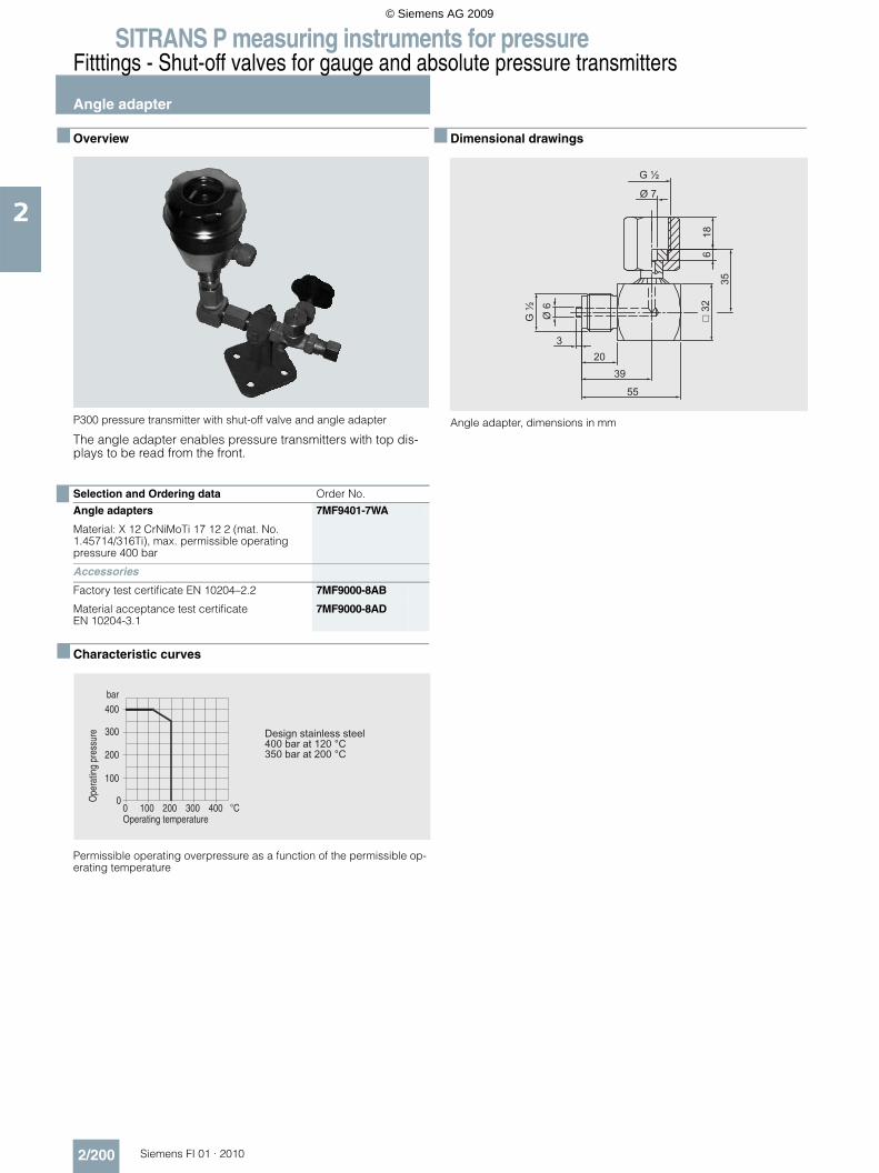
■ Overview
P300 pressure transmitter with shut-off valve and angle adapter
The angle adapter enables pressure transmitters with top dis-plays to be read from the front.
■ Characteristic curves
Permissible operating overpressure as a function of the permissible op-erating temperature
■ Dimensional drawings
Angle adapter, dimensions in mm
Selection and Ordering data Order No.
Angle adapters 7MF9401-7WA
Material: X 12 CrNiMoTi 17 12 2 (mat. No. 1.45714/316Ti), max. permissible operating pressure 400 bar
Accessories
Factory test certificate EN 10204–2.2 7MF9000-8AB
Material acceptance test certificate EN 10204-3.1
7MF9000-8AD
�
���
���
���
������
� ��� ��� ��� ���
����������������������� �������������� ����������
��
��������� ����
�� �������� �� �����
© Siemens AG 2009
SITRANS P measuring instruments for pressureFitttings - Shut-off valves for gauge and absolute pressure transmitters
Double shut-off valves
2/201Siemens FI 01 · 2010
2
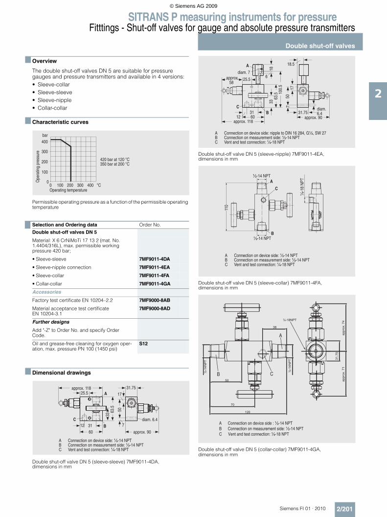
■ Overview
The double shut-off valves DN 5 are suitable for pressure gauges and pressure transmitters and available in 4 versions:• Sleeve-collar• Sleeve-sleeve• Sleeve-nipple• Collar-collar
■ Characteristic curves
Permissible operating pressure as a function of the permissible operating temperature
■ Dimensional drawings
Double shut-off valve DN 5 (sleeve-sleeve) 7MF9011-4DA,dimensions in mm
Double shut-off valve DN 5 (sleeve-nipple) 7MF9011-4EA, dimensions in mm
Double shut-off valve DN 5 (sleeve-collar) 7MF9011-4FA, dimensions in mm
Double shut-off valve DN 5 (collar-collar) 7MF9011-4GA, dimensions in mm
Selection and Ordering data Order No.
Double shut-off valves DN 5
Material: X 6 CrNiMoTi 17 13 2 (mat. No. 1.4404/316L), max. permissible working pressure 420 bar;
• Sleeve-sleeve 7MF9011-4DA
• Sleeve-nipple connection 7MF9011-4EA
• Sleeve-collar 7MF9011-4FA
• Collar-collar 7MF9011-4GA
Accessories
Factory test certificate EN 10204–2.2 7MF9000-8AB
Material acceptance test certificate EN 10204-3.1
7MF9000-8AD
Further designs
Add "-Z" to Order No. and specify Order Code.
Oil and grease-free cleaning for oxygen oper-ation, max. pressure PN 100 (1450 psi)
S12
�
���
���
���
������
� ��� ��� ��� ���
�� ��������� ����
�� �������� �� �����
������������������������������
�,�
��
��!�
�� ����
��!�
��
��!,�
,
��
�����5!����
�����5!�6�
���!��!�
" ��� #�������� ��# ��� $�*/���'78� ��� #��������� ���� � ����� $�*/���'78 9 ����� �� ���#��� #����$�:/���'78
��!,�����
��
��
��!�
��
�
��
�
��!� ��
�!�
��!�
�,��
,
�����5!�6������5!����
���!�!�
���!�,�����5!�����
" ��� #�������� ��# ��� $������ ����%&'�������(�)*(��+��,� ��� #��������� ���� � ����� $�*/���'78 9 ����� �� ���#��� #����$�:/���'78
" ��� #�������� ��# ��� $�*/���'78� ��� #��������� ���� � ����� $�*/���'78 9 ����� �� ���#��� #����$�:/���'78
���
*/���'78
:/���'7
8
*/���'78
�
�
�
B
C
A
A Connection on device side : ½-14 NPTB Connection on measurement side: ½-14 NPTC Vent and test connection: ¼-18 NPT
© Siemens AG 2009

SITRANS P measuring instruments for pressureFitttings - Shut-off valves for gauge and absolute pressure transmittersAccessories forshut-off valves / double shut-off valves
2/202 Siemens FI 01 · 2010
2
■ Overview
The mounting set is suitable for the double shut-off valves 7MF9011-4.A and for wall, rack and pipe mounting.
■ Dimensional drawings
Mounting bracket (7MF9011-8AB) for shut-off valves 7MF9011-4DA and 7MF9011-4EA for wall, rack or pipe mounting, dimensions in mm
Mounting bracket (7MF9011-8AC) for shut-off valves 7MF9011-4FA and 7MF9011-4GA for wall, rack or pipe mounting, dimensions in mm
■ Overview
The instrument brackets are needed to mount the following units:• Pressure gauges with threaded connection at the bottom• Shut-off valves to DIN 16270, DIN 16271 and DIN 16272
(7MF9401-7.. and 7MF9401-8..)
■ Dimensional drawings
Instrument bracket form H, for wall mounting, M56340-A0046/-A0047,dimensions in mm
Instrument bracket form A, wall or pipe mounting,M56340-A0053/-A0079, dimensions in mm
Selection and Ordering data Order No.
Mounting set for shut-off valves
• 7MF9011-4DA und -4EAmade of stainless steel, scope of delivery:1x mounting bracket, 2x hexagon screws M6x40, 1x mounting clip, 2x washers 8.4 to DIN 125;2x hexagon nuts 8.4 to DIN EN 24032
7MF9011-8AB
• 7MF9011-4FA und -4GAmade of stainless steel, scope of delivery:1x mounting bracket, 2x hexagon screws M6x10, 1x mounting clip, 2x washers 8.4 to DIN 125;2x hexagon nuts 8.4 to DIN EN 24032
7MF9011-8AC
hex. 10
65
4
R30
6.5
Ø60.3
85
100
25
115072
9072
90
SW10
Selection and Ordering data Order No.
Instrument bracket, form H, DIN 16281
(e.g. for gauge)made of aluminium alloy, painted black,for wall mounting, screw-type bracket cover• Projection length 60 mm M56340-A0046• Projection length 100 mm M56340-A0047
Instrument bracket, form A, DIN 16281
(e.g. for transmitter)made of annealed cast iron, galvanized and primed for mounting on a wall or rack or or on a sectional rail (horizontal/vertical); Screw-type bracket cover
M56340-A0053
Instrument bracket, form A, DIN 16281
(e.g. for transmitter)made of annealed cast iron, galvanized and primed with pipe clamp for wall and pipe mounting (horizotal/vertical)Screw-type bracket cover
M56340-A0079
��
��
���
��
��� ���
��
��
�,
2��3
2���3
��
��
�����
��
���
��
��
��
��� ��
��
��
© Siemens AG 2009