Embed Size (px)
Citation preview

Radar Transmitters
Quick Start Manual 01/2014
SITRANS LR250 (HART)
SITRANS

mm
mm
m
English
SITRANS LR250 (HART) Quick Start Manual This manual outlines the essential features and functions of the SITRANS LR250 (HART 1)). We strongly advise that you acquire a detailed version of the manual so you can use your device to its fullest potential.
Complete operating instructions can be downloaded from the SITRANS LR250 product page of our web site at: www.siemens.com/LR250. The printed manual is available from your local Siemens Milltronics representative.
Questions about the contents of this manual can be directed to:Siemens AGSiemens Milltronics Process Instruments1954 Technology Drive, P.O. Box 4225Peterborough, Ontario, Canada, K9J 7B1Email: [email protected]
MILLTRONICS is a registered trademark of Siemens Milltronics Process Instruments.
Technical SupportSupport is available 24 hours a day.
To find your local Siemens Automation Office address, phone number, and fax number, go to:
www.siemens.com/automation/partner:• Select the country followed by the City/Region. • Select Technical Support under Service.
For on-line technical support go to: www.siemens.com/automation/support-request • Enter the device name (SITRANS LR250) or order number, then click on Search, and
select the appropriate product type. Click on Next.• Enter a keyword describing your issue. Then either browse the relevant documentation,
or click on Next to email a description of your issue to Siemens Technical Support staff.
Siemens IA/DT Technical Support Center: phone +49 (0)911 895 7222
1) HARTis a registered trademark of HART Communication Foundation.
Copyright Siemens AG 2013. All Rights Reserved Disclaimer of Liability
We encourage users to purchase autho-rized bound manuals, or to view elec-tronic versions as designed and authored by Siemens Milltronics Process Instruments. Siemens Milltronics Pro-cess Instruments will not be responsible for the contents of partial or whole reproductions of either bound or elec-tronic versions.
While we have verified the contents of this manual for agreement with the instrumentation described, variations remain possible. Thus we cannot guar-antee full agreement. The contents of this manual are regularly reviewed and corrections are included in subsequent editions. We welcome all suggestions for improvement.
Technical data subject to change.
A5E31997170 SITRANS LR250 (HART) – QUICK START MANUAL Page EN-1

mm
mm
m
Engl
ish
Safety GuidelinesWarning notices must be observed to ensure personal safety as well as that of others, and to protect the product and the connected equipment. These warning notices are accompanied by a clarification of the level of caution to be observed.
FCC ConformityUS Installations only: Federal Communications Commission (FCC) rules
SITRANS LR250
SITRANS LR250 is a 2-wire 25 GHz pulse radar level transmitter for continuous monitoring of liquids and slurries in storage vessels including high pressure and high temperature, to a range of 20 m (66ft). It is ideal for small vessels and low dielectric media.
The device consists of an electronic circuit coupled to an antenna and either a threaded or flange type process connection.
SITRANS LR250 supports HART communication protocol, and several software packages: SIMATIC PDM, AMS, and FDT/DTM via SITRANS DTM. Signals are processed using Process Intelligence.
WARNING symbol relates to a caution symbol on the product, and means that failure to observe the necessary precautions can result in death, serious injury, and/or considerable material damage.WARNING symbol, used when there is no corresponding caution symbol on the product, means that failure to observe the necessary precautions can result in death, serious injury, and/or considerable material damage.
Note: means important information about the product or that part of the operating manual.
WARNING: Changes or modifications not expressly approved by Siemens Milltronics could void the user’s authority to operate the equipment.
Notes:• This equipment has been tested and found to comply with the limits for a Class A digital
device, pursuant to Part 15 of the FCC Rules. These limits are designed to provide reason-able protection against harmful interference when the equipment is operated in a com-mercial environment.
• This equipment generates, uses, and can radiate radio frequency energy and, if not installed and used in accordance with the operating instructions, may cause harmful interference to radio communications. Operation of this equipment in a residential area is likely to cause harmful interference to radio communications, in which case the user will be required to correct the interference at his own expense.
WARNING: SITRANS LR250 is to be used only in the manner outlined in this manual, otherwise protection provided by the equipment may be impaired.
Note: This product is intended for use in industrial areas. Operation of this equipment in a residential area may cause interference to several frequency based communications.
Page EN-2 SITRANS LR250 (HART) – QUICK START MANUAL A5E31997170

mm
mm
m
English
SpecificationsFor a complete listing, see the SITRANS LR250 (HART) Operating Instructions. For Approvals information see Approvals on page 4.
Ambient/Operating Temperature
Power
• Maximum 30 V DC • 4 to 20 mA• Max. startup current: see Startup Behavior on page 26
Notes: • The maximum temperature is dependent on the process connection, antenna materials,
and vessel pressure: see Maximum Process Temperature Chart on page 25. For more detailed information see Process Pressure/Temperature derating curves in the full operat-ing instructions.
• Process temperature and pressure capabilities are dependent upon information on the process connection tag. The reference drawing listed on the ta is available on the product page of our website at www.siemens.com/LR250, under Support > Installation Drawings > Level Measurement > SITRANS LR250.. Additional information on process connections is available on the Installation Drawings page under Process Connection Diagrams.
• Signal amplitude increases with horn diameter, so use the largest practical size.• Optional extensions can be installed below the threads.• See Maximum Process Temperature Chart on page 25, for more details.
General PurposeIntrinsically SafeNon-sparkingNon-incendive (FM/CSA US/Canada only)
Nominal 24 V DC at 550 Ohm
FlameproofIncreased SafetyExplosion-proof (FM/CSA US/Canada only)
Nominal 24 V DC at 250 Ohm
process temperature at process connection: standard horn antenna (threaded or flanged):
- with FKM O-ring: –40 oC to +200 oC (–40 oF to +392 oF)- with FFKM O-ring: –20 oC to +200 oC (–4 oF to +392 oF)
2" NPT / BSPT / G Threaded PVDF antenna:40 to +80 °C (40 to +176 °F)
Flanged encapsulated antenna (FEA):40 to +170 °C (40 to +338 °F)
ambient temperature(surrounding enclosure)
–40 °C to 80 °C (–40 °F to 176 °F)device nameplate
process connection tag (laser etching on antenna body replaces tag on Flanged encapsulated antenna)
A5E31997170 SITRANS LR250 (HART) – QUICK START MANUAL Page EN-3
mm
mm
m
Engl
ish
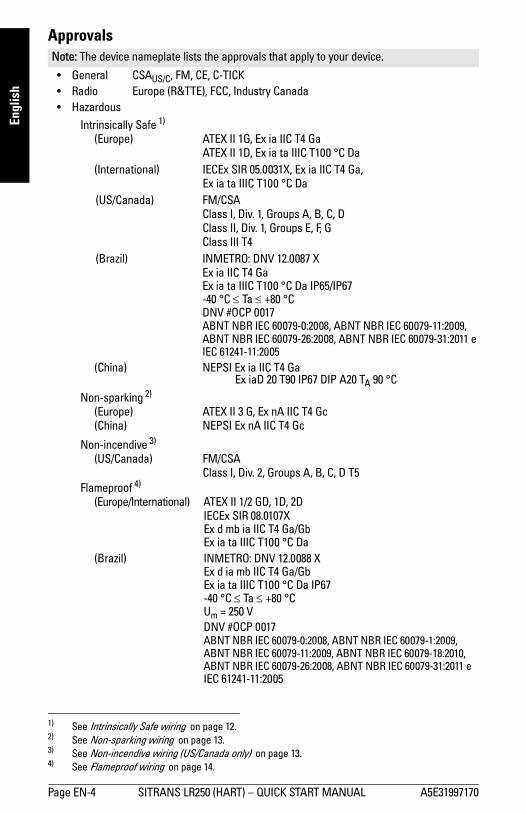
Approvals
• General CSAUS/C, FM, CE, C-TICK• Radio Europe (R&TTE), FCC, Industry Canada• Hazardous
Intrinsically Safe 1)
(Europe) ATEX II 1G, Ex ia IIC T4 GaATEX II 1D, Ex ia ta IIIC T100 °C Da
(International) IECEx SIR 05.0031X, Ex ia IIC T4 Ga, Ex ia ta IIIC T100 °C Da
(US/Canada) FM/CSA Class I, Div. 1, Groups A, B, C, DClass II, Div. 1, Groups E, F, GClass III T4
(Brazil) INMETRO: DNV 12.0087 XEx ia IIC T4 GaEx ia ta IIIC T100 °C Da IP65/IP67-40 °C Ta +80 °CDNV #OCP 0017ABNT NBR IEC 60079-0:2008, ABNT NBR IEC 60079-11:2009,ABNT NBR IEC 60079-26:2008, ABNT NBR IEC 60079-31:2011 eIEC 61241-11:2005
(China) NEPSI Ex ia IIC T4 GaEx iaD 20 T90 IP67 DIP A20 TA 90 °C
Non-sparking 2)
(Europe) ATEX II 3 G, Ex nA IIC T4 Gc(China) NEPSI Ex nA IIC T4 Gc
Non-incendive 3) (US/Canada) FM/CSA
Class I, Div. 2, Groups A, B, C, D T5Flameproof 4)
(Europe/International) ATEX II 1/2 GD, 1D, 2DIECEx SIR 08.0107XEx d mb ia IIC T4 Ga/GbEx ia ta IIIC T100 °C Da
(Brazil) INMETRO: DNV 12.0088 XEx d ia mb IIC T4 Ga/GbEx ia ta IIIC T100 °C Da IP67-40 °C Ta +80 °CUm = 250 VDNV #OCP 0017ABNT NBR IEC 60079-0:2008, ABNT NBR IEC 60079-1:2009,ABNT NBR IEC 60079-11:2009, ABNT NBR IEC 60079-18:2010,ABNT NBR IEC 60079-26:2008, ABNT NBR IEC 60079-31:2011 eIEC 61241-11:2005
Note: The device nameplate lists the approvals that apply to your device.
1) See Intrinsically Safe wiring on page 12.2) See Non-sparking wiring on page 13.3) See Non-incendive wiring (US/Canada only) on page 13.4) See Flameproof wiring on page 14.
Page EN-4 SITRANS LR250 (HART) – QUICK START MANUAL A5E31997170

mm
mm
m
English
• Hazardous (continued)Increased Safety 1)
(Europe/International) ATEX II 1/2 GD, 1D, 2DIECEx SIR 08.0107XEx e mb ia IIC T4 Ga/GbEx ia ta IIIC T100 °C Da
(Brazil) INMETRO: DNV 12.0088 XEx e ia mb IIC T4 Ga/GbEx ia ta IIIC T100 °C Da IP67-40 °C Ta +80 °CUm = 250 VDNV #OCP 0017ABNT NBR IEC 60079-0:2008, ABNT NBR IEC 60079-7:2008,ABNT NBR IEC 60079-11:2009, ABNT NBR IEC 60079-18:2010,ABNT NBR IEC 60079-26:2008, ABNT NBR IEC 60079-31:2011 eIEC 61241-11:2005
Flameproof/Increased Safety(China) NEPSI Ex d ia mb IIC T4 Ga/Gb / Ex e ia mb IIC T4 Ga/Gb
Ex iaD 20 T90 IP67 DIP A20 TA 90 oCExplosion proof 2)
(US/Canada) FM/CSAClass I, Div. 1, Groups A, B, C, DClass II, Div. 1, Groups E, F, GClass III T4
• MarineLloyd’s Register of ShippingABS Type Approval
1) See Increased safety wiring on page 14.2) See Explosion-proof wiring (US/Canada only) on page 14.
A5E31997170 SITRANS LR250 (HART) – QUICK START MANUAL Page EN-5

mm
mm
m
Engl
ish
Pressure Application
Pressure Equipment Directive, PED, 97/23/ECSiemens Level Transmitters with flanged, threaded, or sanitary clamp type process mounts have no pressure-bearing housing of their own and, therefore, do not come under the Pressure Equipment Directive as pressure or safety accessories, (see EU Commission Guideline 1/8 and 1/20). 1)
WARNINGS:
• Never attempt to loosen, remove, or disassemble process connection or device housing while vessel contents are under pressure.
• The user is responsible for the selection of bolting and gasket (except for Flanged encapsulated antenna) materials which will fall within the limits of the flange and its intended use and which are suitable for the service condi-tions.
• For Flanged encapsulated antenna, lens acts as integral gasket, no other required.
• Use spring washers for Flanged encapsulated antenna.• Improper installation may result in loss of process pressure.Notes:• The process connection tag shall remain with the process pressure boundary assembly1). • SITRANS LR250 units are hydrostatically tested, meeting or exceeding the requirements of
the ASME Boiler and Pressure Vessel Code and the European Pressure Equipment Direc-tive.
1) The process pressure boundary assembly comprises the components that act as a barrier against pressure loss from the process vessel: that is, the combination of process connection body and emit-ter, but normally excluding the electrical enclosure.
Page EN-6 SITRANS LR250 (HART) – QUICK START MANUAL A5E31997170

mm
mm
m
English
Installation
Nozzle design
• The end of the antenna must protrude a minimum of 10 mm (0.4”) to avoid false echoes being reflected from the nozzle 1).
• Minimum recommended nozzle diameter for the threaded PVDF antenna is 50 mm (2").• An antenna extension (100 mm/ 3.93") is available for any version except the Threaded
PVDF and the Flanged encapsulated antenna (FEA).• The maximum nozzle length for the FEA is 500 mm (20").
WARNINGS:• Installation shall only be performed by qualified personnel and in accor-
dance with local governing regulations.• Handle the device using the enclosure not the process connection tag, to avoid
damage.• Take special care when handling the threaded PVDF and Flanged encapsu-
lated antennas. Any damage to the antenna surface, particularly to the tip/lens, could affect performance.
• Materials of construction are chosen based on their chemical compatibility (or inertness) for general purposes. For exposure to specific environments, check with chemical compatibility charts before installing.
Notes:• For European Union and member countries, installation must be according to ETSI EN
302372.• Refer to the device nameplate for approval information.• The serial numbers stamped in each process connection body provide a unique identifica-
tion number indicating date of manufacture.Example: MMDDYY – XXX (where MM = month, DD = day, YY = year, and XXX= sequential
unit produced)
• Further markings (space permitting) indicate flange configuration, size, pressure class, material, and material heat code.
1) Not applicable for FEA
min. clearance: 10 mm (0.4")
Threaded PVDF antenna
Flanged encapsulated antenna
min. dia. 50 mm (2")
Stainless steel horn antenna
min. dia. 50 mm (2")
max. nozzle length: 500 mm (20")
min. clearance: 10 mm (0.4")
A5E31997170 SITRANS LR250 (HART) – QUICK START MANUAL Page EN-7

mm
mm
m
Engl
ish
Nozzle location• Avoid central locations on tall, narrow vessels,
which can generate false echoes.• Nozzle must be vertical.
Environment• Provide an environment suitable to the housing
rating and materials of construction.• Provide a sunshield if the device will be mounted
in direct sunlight.
Beam angle
• Beam angle is the width of the cone where the energy density is half of the peak energy density.
• The peak energy density is directly in front of and in line with the antenna.• There is a signal transmitted outside the beam angle, therefore false targets may be
detected.
Emission Cone• Keep emission cone free of interference from ladders, pipes, I-beams or filling streams.
Access for programming
• Provide easy access for viewing the display and programming via the handheld program-mer.
preferred
undesirable
emission cone
emission cone
emission cone
beam angle
beam angle
beam angle
beam angle = 19°beam angle:size beam angle2"/DN50/50A = 12.8°3"/DN80/80A = 9.6°4"/DN100/100A = 9.6°6"/DN150/150A = 9.6°
beam angle:size beam angle1.5" = 19°2" = 15°3" = 10°4" = 8°
Hornantenna
Flanged encapsulatedantenna (FEA)
Threaded PVDF antenna
Page EN-8 SITRANS LR250 (HART) – QUICK START MANUAL A5E31997170
mm
mm
m
English
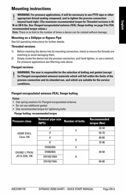
Mounting instructions
Mounting on a Stillpipe or Bypass PipeSee full operating instructions for further details.
Threaded versions
1) Before inserting the device into its mounting connection, check to ensure the threads are matching to avoid damaging them.
2) Simply screw the device into the process connection, and hand tighten, or use a wrench. For pressure applications see Warning note above.
Flanged versions
Flanged encapsulated antenna (FEA), flange bolting
Flange bolting: recommended torque
WARNING: For pressure applications, it will be necessary to use PTFE tape or other appropriate thread sealing compound, and to tighten the process connection beyond hand-tight. (The maximum recommended torque for Threaded versions is 40
N-m (30 ft.lbs. See Flanged encapsulated antenna (FEA), flange bolting on page 9 for FEA recommended torque values.)Note: There is no limit to the number of times a device can be rotated without damage.
WARNING: The user is responsible for the selection of bolting and gasket (except for Flanged encapsulated antenna) materials which will fall within the limits of the process connection and its intended use, and which are suitable for the service conditions.
Notes: • Use spring washers for Flanged encapsulated antenna.• Do not use additional gasket• Use recommended torque for tightening bolts
Pressure class Nominal pipe size (NPS) Number of bolts Recommended
torque (Nm)
ASME B16.5, Class 150
2"4
30-50
3" 50-70
4"8
40-60
6" 70-90
EN1092-1, PN16/JIS B 2220, 10K
DN50/50A 4
30-50DN80/80A
8DN100/100A
DN150/150A 60-80
A5E31997170 SITRANS LR250 (HART) – QUICK START MANUAL Page EN-9

mm
mm
m
Engl
ish
Recommendations for flange bolting:• Use cross-pattern sequence as shown• Check uniformity of the flange gap• Apply adjustments by selecting tightening if required• Torque incrementally until desired value is reached• Check/re-torque after 4 to 6 hours• Check bolts periodically, re-torque as required• Use new lens, O-ring and spring washers after removal from installation (see full operat-
ing instructions for part numbers)
1
1
2
4
8
6
3
5
1-3-2-4
1-5-3-7 2-6-4-8
2
3
4
7
Page EN-10 SITRANS LR250 (HART) – QUICK START MANUAL A5E31997170

mm
mm
m
English
WiringPower
Connecting SITRANS LR250
1) Strip the cable jacket for approximately 70 mm (2.75") from the end of the cable, and thread the wires through the gland. (If cable is routed through conduit, use only approved suitable-size hubs for waterproof applications.) 1) 2)
2) Connect the wires to the terminal as shown: the polarity is identified on the terminal block.
3) Ground the device according to local regulations.4) Tighten the gland to form a good seal.5) Close the lid before programming and device configuration.
WARNINGS:The DC input terminals shall be supplied from a source providing electrical isolation between the input and output, in order to meet the applicable safety requirements of IEC 61010-1.
All field wiring must have insulation suitable for rated voltages.
WARNINGS: • Check the device nameplate to verify the approval rating.• Use appropriate conduit seals to maintain IP or NEMA rating.• See Wiring setups for hazardous area installations on page 12.Notes: • Use twisted pair cable: AWG 22 to 14 (0.34 mm2 to 2.5 mm2).• Separate cables and conduits may be required to conform to standard instrumentation
wiring practices or electrical codes.
1) May be shipped with the device.2) If cable is routed through conduit, use only approved suitable-size hubs for waterproof applications.
cable shield (if used)
Use a 2 mm Allen key to loosen the lid-lock set screw.
optional cable gland1) 2) (or NPT cable entry2))
plug (IP 68)
A5E31997170 SITRANS LR250 (HART) – QUICK START MANUAL Page EN-11
mm
mm
m
Engl
ish
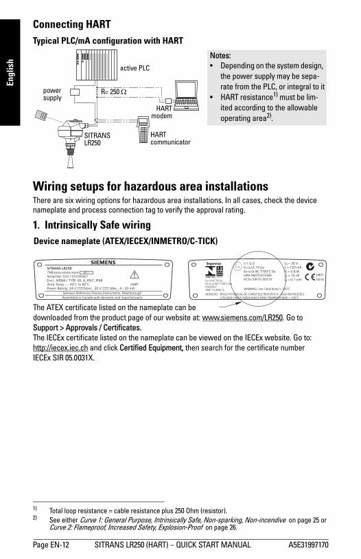
Connecting HARTTypical PLC/mA configuration with HART 1) 2)
Wiring setups for hazardous area installationsThere are six wiring options for hazardous area installations. In all cases, check the device nameplate and process connection tag to verify the approval rating.
1. Intrinsically Safe wiring
1) Total loop resistance = cable resistance plus 250 Ohm (resistor). 2) See either Curve 1: General Purpose, Intrinsically Safe, Non-sparking, Non-incendive on page 25 or
Curve 2: Flameproof, Increased Safety, Explosion-Proof on page 26.
active PLC
HARTmodem
SITRANS LR250
power supply
R= 250
HART communicator
Notes: • Depending on the system design,
the power supply may be sepa-rate from the PLC, or integral to it
• HART resistance1) must be lim-ited according to the allowable operating area2).
SITRANS LR250
Siemens Milltronics Process Instruments, Peterborough
7MLxxxx-xxxxx-xxxx-
Encl.: NEMA / TYPE 4X, 6, IP67, IP68Amb.Temp.: – 40°C to 80°CPower Rating: 24 V Max., 4 - 20 mANom., 30 V
Serial No: GYZ / S1034567
HART
Ui = 30 VIi = 120 mAPi = 0.8 WCi = 15 nFLi = 0.1 mHEx ia IIC T4 Ga
Ex ia ta IIIC T100°C DaIP65/IP67DNV 12.0087 X
0518
0891
ATENÇÃO - RISCO POTENCIAL DE CARGA ELETROSTÁTICA - VEJA INSTRUÇÕES- UTILIZAR CABOS ADEQUADOS PARA TEMPERATURAS > 100°C
BOX 1
Assembled in Canada with domestic and imported parts
II 1 G DEx ia IIC T4 GaEx ia ta IIIC T100°C DaSIRA 06ATEX2358XIECEx SIR 05.0031X
KCC-REM-S49SITRANSLR
OCP 0017
WARNING: Use Cable Rated > 100°C
Device nameplate (ATEX/IECEX/INMETRO/C-TICK)
The ATEX certificate listed on the nameplate can be downloaded from the product page of our website at: www.siemens.com/LR250. Go to Support > Approvals / Certificates.The IECEx certificate listed on the nameplate can be viewed on the IECEx website. Go to: http://iecex.iec.ch and click Certified Equipment, then search for the certificate number IECEx SIR 05.0031X.
Page EN-12 SITRANS LR250 (HART) – QUICK START MANUAL A5E31997170
mm
mm
m
English
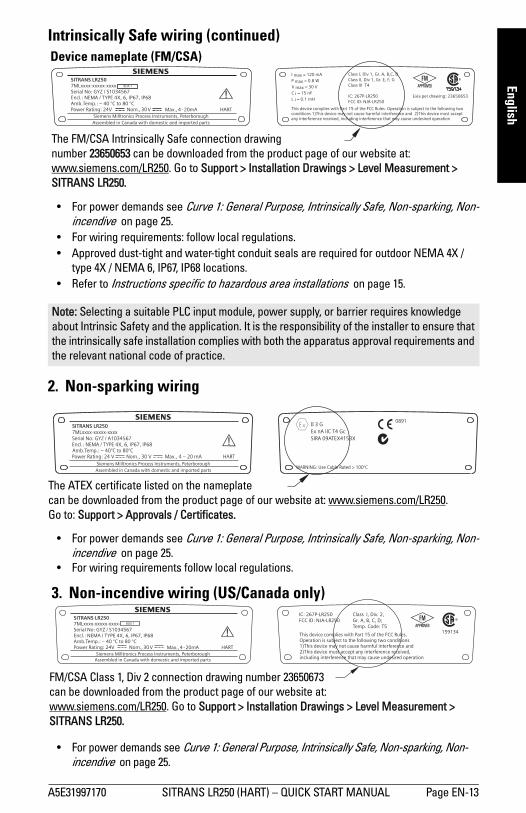
Intrinsically Safe wiring (continued)
• For power demands see Curve 1: General Purpose, Intrinsically Safe, Non-sparking, Non-incendive on page 25.
• For wiring requirements: follow local regulations. • Approved dust-tight and water-tight conduit seals are required for outdoor NEMA 4X /
type 4X / NEMA 6, IP67, IP68 locations.• Refer to Instructions specific to hazardous area installations on page 15.
2. Non-sparking wiring
• For power demands see Curve 1: General Purpose, Intrinsically Safe, Non-sparking, Non-incendive on page 25.
• For wiring requirements follow local regulations.
• For power demands see Curve 1: General Purpose, Intrinsically Safe, Non-sparking, Non-incendive on page 25.
Note: Selecting a suitable PLC input module, power supply, or barrier requires knowledge about Intrinsic Safety and the application. It is the responsibility of the installer to ensure that the intrinsically safe installation complies with both the apparatus approval requirements and the relevant national code of practice.
Exia per drawing: 23650653
R
Class I, Div 1, Gr. A, B,C, DClass II, Div 1, Gr. E, F, GClass III T4
This device complies with Part 15 of the FCC Rules. Operation is subject to the following twoconditions 1)This device may not cause harmful interference and 2)This device must acceptany interference received, including interference that may cause undesired operation
IC: 267P-LR250FCC ID: NJA-LR250
SITRANS LR250
7MLxxxx-xxxxx-xxxx-Serial No: GYZ / S1034567Encl.: NEMA / TYPE 4X, 6, IP67, IP68Amb.Temp.: – 40 °C to 80 °CPower Rating: 24V Max., 4 -20mANom.,30V
Siemens Milltronics Process Instruments, PeterboroughHART
P max = 0.8 W
C i = 15 nFV max = 30 V
L i = 0.1 mH
I max = 120 mA
BOX 1
Assembled in Canada with domestic and imported parts
The FM/CSA Intrinsically Safe connection drawing number 23650653 can be downloaded from the product page of our website at: www.siemens.com/LR250. Go to Support > Installation Drawings > Level Measurement > SITRANS LR250.
Device nameplate (FM/CSA)
KCC-REM-S49SITRANSLR
SITRANS LR250
Assembled in Canada with domestic and imported partsSiemens Milltronics Process Instruments, Peterborough
7MLxxxx-xxxxx-xxxx
Encl.: NEMA / TYPE 4X, 6, IP67, IP68Amb.Temp.: – 40°C to 80°CPower Rating: 24 V Nom., 30 V Max., 4 – 20 mA HART
Serial No: GYZ / A1034567
3 GEx nA IIC T4 GcSIRA 09ATEX4153X
II0891
WARNING: Use Cable Rated > 100°C
KCC-REM-S49SITRANSLR
The ATEX certificate listed on the nameplate can be downloaded from the product page of our website at: www.siemens.com/LR250.Go to: Support > Approvals / Certificates.
Class I, Div. 2,Gr. A, B, C, D;Temp. Code: T5
This device complies with Part 15 of the FCC Rules.Operation is subject to the following two conditions1)This device may not cause harmful interference and2)This device must accept any interference received,including interference that may cause undesired operation
IC: 267P-LR250FCC ID: NJA-LR250
159134
SITRANS LR250
7MLxxxx-xxxxx-xxxx-Serial No: GYZ / S1034567Encl.: NEMA / TYPE 4X, 6, IP67, IP68Amb.Temp.: – 40 °C to 80 °CPower Rating: 24V Max., 4 -20mANom., 30V
Siemens Milltronics Process Instruments, PeterboroughHART
BOX 1
Assembled in Canada with domestic and imported parts
FM/CSA Class 1, Div 2 connection drawing number 23650673can be downloaded from the product page of our website at: www.siemens.com/LR250. Go to Support > Installation Drawings > Level Measurement > SITRANS LR250.
3. Non-incendive wiring (US/Canada only)
A5E31997170 SITRANS LR250 (HART) – QUICK START MANUAL Page EN-13

mm
mm
m
Engl
ish
• For power demands see Curve 2: Flameproof, Increased Safety, Explosion-Proof on page 26. • For wiring requirements follow local regulations.• See also Instructions specific to hazardous area installations on page 15 and the ATEX
certificate listed above.
• For power demands see Curve 2: Flameproof, Increased Safety, Explosion-Proof on page 26. • For wiring requirements follow local regulations.• See also Instructions specific to hazardous area installations on page 15 and the ATEX
certificate listed above.
• For power demands see Curve 2: Flameproof, Increased Safety, Explosion-Proof on page 26.
II G D, 1 D, 2 DEx d mb ia IIC T4 Ga/GbEx ia ta IIIC T100°C DaSIRA 08ATEX1301XIECEx SIR 08.0107X
1/2
Um = 250 VWARNING: – De-Energize Before Removing Cover
– Use Cable Rated >100°C
0518
0891SITRANS LR250
Assembled in Canada with domestic and imported partsSiemens Milltronics Process Instruments, Peterborough
7MLxxxx-xxxxx-x
Encl.: NEMA / TYPE 4X, 6, IP67, IP68Amb.Temp.: – 40°C to 80°CPower Rating: 24 V Max., 4 - 20 mANom., 30 V
Serial No: GYZ / A1034567
s
ATENÇÃO: N– ÃO ABRA QUANDO ENERGIZADO– UTILIZAR CABOS ADEQUADOS PARA
TEMPERATURAS > 100 °C
KCC-RES-S49SITRANSL
HART
Ex d ia mb IIC T4 Ga/GbEx ia ta IIIC T100°C DaDNV 12.0088 X
OCP 0017
The ATEX certificate listed on the nameplate can be downloaded from the product page of our website at: www.siemens.com/LR250. Go to: Support > Approvals / Certificates.The IECEx certificate listed on the nameplate can be viewed on the IECEx website. Go to: http://iecex.iec.ch and and click Certified Equipment, then search for the certificate number IECEx SIR 08.0107X.
4. Flameproof wiring
KCC-REM-S49SITRANSL
SITRANS LR250
Assembled in Canada with domestic and imported partsSiemens Milltronics Process Instruments, Peterborough
7MLxxxx-xxxxx-xxxx-x
Encl.: NEMA / TYPE 4X, 6, IP67, IP68Amb.Temp.: – 40°C to 80°CPower Rating: 24 V Max., 4 - 20 mANom., 30 V
Serial No: GYZ / A1034567
HART
s
Ex e mb ia IIC T4 Ga/GbEx ia ta IIIC T100°C Da
IECEx SIR 08.0107XSIRA 08ATEX1301X
Um = 250 VWARNING: – De-Energize Before Removing Cover
– Use Cable Rated > 100°C
0518
0891
ATENÇÃO: – NÃO ABRA QUANDO ENERGIZAD0– UTILIZAR CABOS ADEQUADOS PARA
TEMPERATURAS > 100 °C
KCC-REM-S49SITRANSL
G D, 1 D, 2 DII 1/2
Ex e ia mb IIC T4 Ga/GbEx ia ta IIIC T100°C DaDNV 12.0088 X
OCP 0017
The ATEX certificate listed on the nameplatecan be downloaded from the product page of our website at: www.siemens.com/LR250. Go to: Support > Approvals / Certificates.The IECEx certificate listed on the nameplate can be viewed on the IECEx website. Go to: http://iecex.iec.ch and and click Certified Equipment, then search for the certificate number IECEx SIR 08.0107X.
5. Increased safety wiring
SITRANS LR250
Assembled in Canada with domestic and imported partsSiemens Milltronics Process Instruments, Peterborough
7ML5431-xxxxx-xxHx
Encl.: NEMA / TYPE 4X, 6, IP67, IP68Amb.Temp.: – 40 °C to 80 °CPower Rating: 24V Max., 4 - 20mANom., 30 V
Serial No: GYZ / C1034567
HARTWARNING: Do Not RemoveCover While Circuits Are Live
FCC ID:NJA-LR250DE
Class I ;Div1;Group A, B, C, DClass II ;Div1;Group E,F, GClass IIITemp. Code: T4Perdrawing: A5E02257843
IC: 267P-LR250DE
This device complies with Part 15 of the FCC Rules.Operation is subject to the following two conditions1) This device may not cause harmful interference and2) This device must accept any interference received,
including interference that may causeundesired operation
159134
FM/CSA Explosion Proof connection drawing number A5E02257843 can be downloaded from the product page of our website at: www.siemens.com/LR250. Go to Support > Installation Drawings > Level Measurement > SITRANS LR250.
6. Explosion-proof wiring (US/Canada only)
Page EN-14 SITRANS LR250 (HART) – QUICK START MANUAL A5E31997170
mm
mm
m
English
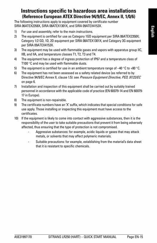
Instructions specific to hazardous area installations (Reference European ATEX Directive 94/9/EC, Annex II, 1/0/6)
The following instructions apply to equipment covered by certificate number SIRA 06ATEX2358X, SIRA 08ATEX1301X, and SIRA 09ATEX4153X.
1) For use and assembly, refer to the main instructions.2) The equipment is certified for use as Category 1GD equipment per SIRA 06ATEX2358X;
Category 1/2 GD, 1D, 2D equipment per SIRA 08ATEX1301X; and Category 3G equipment per SIRA 09ATEX4153X.
3) The equipment may be used with flammable gases and vapors with apparatus group IIC, IIB, and IIA, and temperature classes T1, T2, T3 and T4.
4) The equipment has a degree of ingress protection of IP67 and a temperature class of T100 C and may be used with flammable dusts.
5) The equipment is certified for use in an ambient temperature range of –40 C to +80 C.6) The equipment has not been assessed as a safety related device (as referred to by
Directive 94/9/EC Annex II, clause 1.5): see Pressure Equipment Directive, PED, 97/23/EC on page 6.
7) Installation and inspection of this equipment shall be carried out by suitably trained personnel in accordance with the applicable code of practice (EN 60079-14 and EN 60079-17 in Europe).
8) The equipment is non-repairable.9) The certificate numbers have an ‘X’ suffix, which indicates that special conditions for safe
use apply. Those installing or inspecting this equipment must have access to the certificates.
10) If the equipment is likely to come into contact with aggressive substances, then it is the responsibility of the user to take suitable precautions that prevent it from being adversely affected, thus ensuring that the type of protection is not compromised.
- Aggressive substances: for example, acidic liquids or gases that may attack metals, or solvents that may affect polymeric materials.
- Suitable precautions: for example, establishing from the material’s data sheet that it is resistant to specific chemicals.
A5E31997170 SITRANS LR250 (HART) – QUICK START MANUAL Page EN-15
mm
mm
m
Engl
ish
Programming SITRANS LR250• See Quick Start Wizard via the handheld programmer on page 20.• See Quick Start Wizard via SIMATIC PDM on page 23.
Activating SITRANS LR250Power up the device. SITRANS LR250 automatically starts up in Measurement mode.
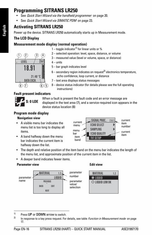
The LCD Display
Measurement mode display ( normal operation) 1) 2)(((
Fault present indicators
Program mode displayNavigation view
• A visible menu bar indicates the menu list is too long to display all items.
• A band halfway down the menu bar indicates the current item is halfway down the list.
• The depth and relative position of the item band on the menu bar indicates the length of the menu list, and approximate position of the current item in the list.
• A deeper band indicates fewer items.
1) Press UP or DOWN arrow to switch.2) In response to a key press request. For details, see table Function in Measurement mode on page
17.
1 – toggle indicator1) for linear units or %2 – selected operation: level, space, distance, or volume3 – measured value (level or volume, space, or distance)4 – units5 – bar graph indicates level
6 – secondary region indicates on request2) electronics temperature, echo confidence, loop current, or distance
7 – text area displays status messages 8 – device status indicator (for details please see the full operating
instructions) 678
1 3 42
5
S: 0 LOEWhen a fault is present the fault code and an error message are displayed in the text area (7), and a service-required icon appears in the device status location (8)
current item number
current item
current menu
item band
menu bar
parameter value/selection
parameter numberparameter
name
Edit viewParameter view
Page EN-16 SITRANS LR250 (HART) – QUICK START MANUAL A5E31997170
mm
mm
m
English
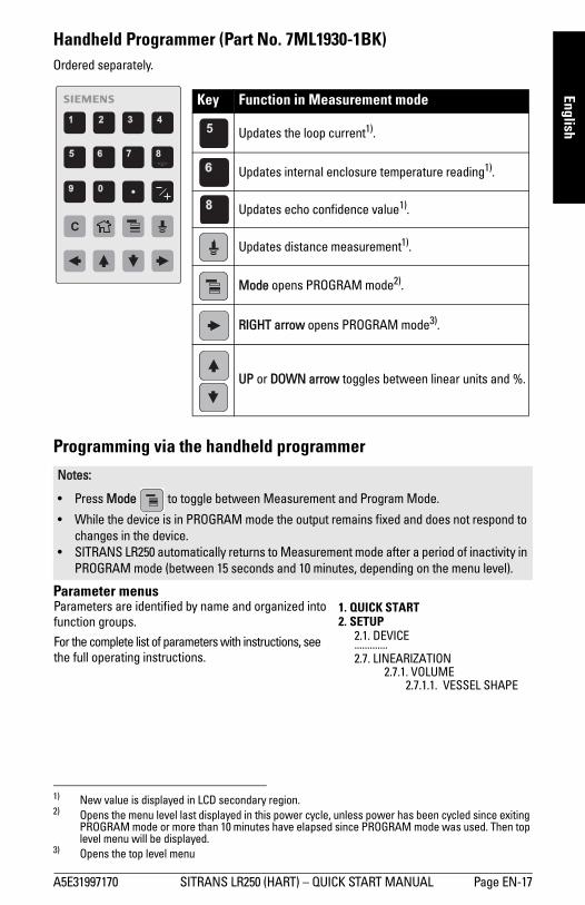
Handheld Programmer (Part No. 7ML1930-1BK)Ordered separately. 1) 2) 3)
Programming via the handheld programmer
Parameter menus
1) New value is displayed in LCD secondary region.2) Opens the menu level last displayed in this power cycle, unless power has been cycled since exiting
PROGRAM mode or more than 10 minutes have elapsed since PROGRAM mode was used. Then top level menu will be displayed.
3) Opens the top level menu
Notes:
• Press Mode to toggle between Measurement and Program Mode.
• While the device is in PROGRAM mode the output remains fixed and does not respond to changes in the device.
• SITRANS LR250 automatically returns to Measurement mode after a period of inactivity in PROGRAM mode (between 15 seconds and 10 minutes, depending on the menu level).
C
Key Function in Measurement mode
Updates the loop current1).
Updates internal enclosure temperature reading1).
Updates echo confidence value1).
Updates distance measurement1).
Mode opens PROGRAM mode2).
RIGHT arrow opens PROGRAM mode3).
UP or DOWN arrow toggles between linear units and %.
Parameters are identified by name and organized into function groups.
For the complete list of parameters with instructions, see the full operating instructions.
1. QUICK START2. SETUP
2.1. DEVICE.............2.7. LINEARIZATION
2.7.1. VOLUME2.7.1.1. VESSEL SHAPE
A5E31997170 SITRANS LR250 (HART) – QUICK START MANUAL Page EN-17

mm
mm
m
Engl
ish
1. Enter PROGRAM mode• Point the programmer at the display (from a maximum
distance of 300 mm [1 ft.]).
• RIGHT arrow activates PROGRAM mode and opens menu level 1.
• Mode opens the menu level last displayed in PROGRAM mode within the last 10 minutes, or menu level 1 if power has been cycled since then.
2. Navigating: key functions in Navigation mode
3. Editing in PROGRAM modeSelecting a listed option
a) Navigate to the desired parameter.
b) Press RIGHT arrow to open parameter view.
c) Press RIGHT arrow again to open Edit
mode. The current selection is highlighted.Scroll to a new selection.
d) Press RIGHT arrow to accept it
The LCD returns to parameter view and displays the new selection.
Note: For Quick Access to parameters via the handheld programmer, press Home , then enter the menu number, for example: 2.7.1 (Volume).
Key Name Menu level Function in Navigation Mode
UP or DOWN arrow
menu or parameter Scroll to previous or next menu or parameter.
RIGHT arrow menu Go to first parameter in the selected menu, or open
next menu.
parameter Open Edit mode.
LEFT arrow menu or parameter Open parent menu.
Mode menu or parameter Change to MEASUREMENT mode.
Home menu or parameter Open top level menu: menu 1.
display
handheld programmer
Max. 300 mm(1 ft)
parameter name parameternumber
current selection
Page EN-18 SITRANS LR250 (HART) – QUICK START MANUAL A5E31997170
mm
mm
m
English
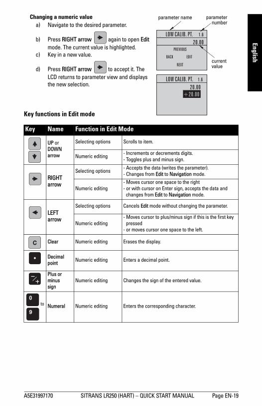
Changing a numeric valuea) Navigate to the desired parameter.
b) Press RIGHT arrow again to open Edit mode. The current value is highlighted.
c) Key in a new value.
d) Press RIGHT arrow to accept it. The LCD returns to parameter view and displays the new selection.
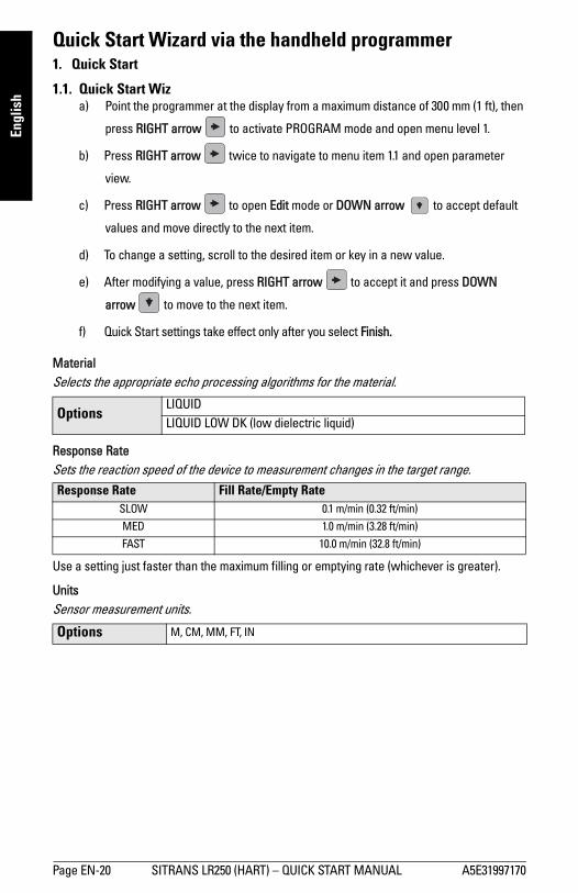
Key functions in Edit mode
Key Name Function in Edit Mode
UP or DOWN arrow
Selecting options Scrolls to item.
Numeric editing - Increments or decrements digits.- Toggles plus and minus sign.
RIGHT arrow
Selecting options - Accepts the data (writes the parameter).- Changes from Edit to Navigation mode.
Numeric editing - Moves cursor one space to the right- or with cursor on Enter sign, accepts the data and
changes from Edit to Navigation mode.
LEFT arrow
Selecting options Cancels Edit mode without changing the parameter.
Numeric editing - Moves cursor to plus/minus sign if this is the first key
pressed- or moves cursor one space to the left.
Clear Numeric editing Erases the display.
Decimal point Numeric editing Enters a decimal point.
Plus or minus sign
Numeric editing Changes the sign of the entered value.
to
o
Numeral Numeric editing Enters the corresponding character.
current value
parameternumber
parameter name
A5E31997170 SITRANS LR250 (HART) – QUICK START MANUAL Page EN-19
mm
mm
m
Engl
ish
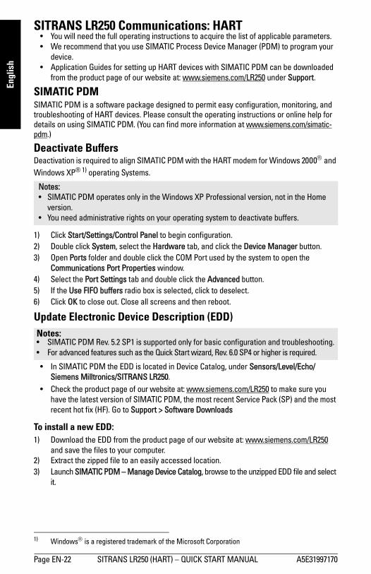
Quick Start Wizard via the handheld programmer1. Quick Start
1.1. Quick Start Wiza) Point the programmer at the display from a maximum distance of 300 mm (1 ft), then
press RIGHT arrow to activate PROGRAM mode and open menu level 1.
b) Press RIGHT arrow twice to navigate to menu item 1.1 and open parameter
view.
c) Press RIGHT arrow to open Edit mode or DOWN arrow to accept default
values and move directly to the next item.
d) To change a setting, scroll to the desired item or key in a new value.
e) After modifying a value, press RIGHT arrow to accept it and press DOWN
arrow to move to the next item.
f) Quick Start settings take effect only after you select Finish.
MaterialSelects the appropriate echo processing algorithms for the material.
Response RateSets the reaction speed of the device to measurement changes in the target range.
Use a setting just faster than the maximum filling or emptying rate (whichever is greater).
UnitsSensor measurement units.
OptionsLIQUIDLIQUID LOW DK (low dielectric liquid)
Response Rate Fill Rate/Empty RateSLOW 0.1 m/min (0.32 ft/min)
MED 1.0 m/min (3.28 ft/min)
FAST 10.0 m/min (32.8 ft/min)
Options M, CM, MM, FT, IN
Page EN-20 SITRANS LR250 (HART) – QUICK START MANUAL A5E31997170

mm
mm
m
English
OperationLow Calibration PointDistance from Sensor Reference to Low Calibration Point: usually process empty level. See Operation for an illustration.
High Calibration PointDistance from Sensor Reference to High Calibration Point: usually process full level. See Operation for an illustration.
Wizard completeIn order to save the Quick Start settings it is necessary to select Finish to apply changes.
Press Down arrow (Finish). Then press LEFT arrow to return to Measurement mode. SITRANS LR250 is now ready to operate.
Operation DescriptionNO
SERVICEMeasurement and associated loop current are not updated, and the device defaults to Fail-safe mode1).
1) For more details on Fail-safe Mode see the full operating instructions.
LEVEL Distance to material surface referenced from Low Calibration Point.
SPACE Distance to material surface referenced from High Calibration Point.
DISTANCE Distance to material surface referenced from Sensor Reference Point.
Values Range: 0.00 to 20.00 m
Values Range: 0.00 to 20.00 m
Options BACK, CANCEL, FINISH (Display returns to 1.1 Quick Start Wiz menu when Quick Start is successfully completed.)
Note: If your application has a tank with obstructions, please see the full operating instructions for details on using Auto False Echo Suppression.
High Cal. Point
Low Cal. Point
level
space
distancesensor reference point
sensor reference point (flanged versions)
sensor reference point (threaded versions)
sensor reference point (flanged encapsulated)
A5E31997170 SITRANS LR250 (HART) – QUICK START MANUAL Page EN-21
mm
mm
m
Engl
ish
SITRANS LR250 Communications: HART• You will need the full operating instructions to acquire the list of applicable parameters.• We recommend that you use SIMATIC Process Device Manager (PDM) to program your
device.• Application Guides for setting up HART devices with SIMATIC PDM can be downloaded
from the product page of our website at: www.siemens.com/LR250 under Support.
SIMATIC PDMSIMATIC PDM is a software package designed to permit easy configuration, monitoring, and troubleshooting of HART devices. Please consult the operating instructions or online help for details on using SIMATIC PDM. (You can find more information at www.siemens.com/simatic-pdm.)
Deactivate BuffersDeactivation is required to align SIMATIC PDM with the HART modem for Windows 2000 and Windows XP® 1) operating Systems.
1) Click Start/Settings/Control Panel to begin configuration.2) Double click System, select the Hardware tab, and click the Device Manager button.3) Open Ports folder and double click the COM Port used by the system to open the
Communications Port Properties window.4) Select the Port Settings tab and double click the Advanced button.5) If the Use FIFO buffers radio box is selected, click to deselect. 6) Click OK to close out. Close all screens and then reboot.
Update Electronic Device Description (EDD)
• In SIMATIC PDM the EDD is located in Device Catalog, under Sensors/Level/Echo/Siemens Milltronics/SITRANS LR250.
• Check the product page of our website at: www.siemens.com/LR250 to make sure you have the latest version of SIMATIC PDM, the most recent Service Pack (SP) and the most recent hot fix (HF). Go to Support > Software Downloads
To install a new EDD:1) Download the EDD from the product page of our website at: www.siemens.com/LR250
and save the files to your computer.2) Extract the zipped file to an easily accessed location. 3) Launch SIMATIC PDM – Manage Device Catalog, browse to the unzipped EDD file and select
it.
Notes: • SIMATIC PDM operates only in the Windows XP Professional version, not in the Home
version.• You need administrative rights on your operating system to deactivate buffers.
1) Windows is a registered trademark of the Microsoft Corporation
Notes: • SIMATIC PDM Rev. 5.2 SP1 is supported only for basic configuration and troubleshooting. • For advanced features such as the Quick Start wizard, Rev. 6.0 SP4 or higher is required.
Page EN-22 SITRANS LR250 (HART) – QUICK START MANUAL A5E31997170
mm
mm
m
English
Configuring a new device
1) Check that you have the most recent EDD, and if necessary update it (seeUpdate Electronic Device Description (EDD) on page 22).
2) Launch SIMATIC Manager and create a new project for the device.
3) Open the menu Device – Master Reset and click on OK to perform a reset to Factory Defaults.
4) After the reset is complete, upload parameters to the PC/PG.
5) Configure the device via the Quick Start wizard.
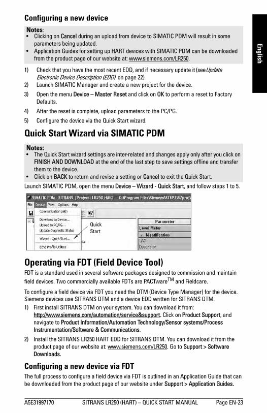
Quick Start Wizard via SIMATIC PDM
Launch SIMATIC PDM, open the menu Device – Wizard - Quick Start, and follow steps 1 to 5.
Operating via FDT (Field Device Tool)FDT is a standard used in several software packages designed to commission and maintain field devices. Two commercially available FDTs are PACTwareTM and Fieldcare.
To configure a field device via FDT you need the DTM (Device Type Manager) for the device. Siemens devices use SITRANS DTM and a device EDD written for SITRANS DTM.1) First install SITRANS DTM on your system. You can download it from:
http://www.siemens.com/automation/service&support. Click on Product Support, and navigate to Product Information/Automation Technology/Sensor systems/Process Instrumentation/Software & Communications.
2) Install the SITRANS LR250 HART EDD for SITRANS DTM. You can download it from the product page of our website at: www.siemens.com/LR250. Go to Support > Software Downloads.
Configuring a new device via FDTThe full process to configure a field device via FDT is outlined in an Application Guide that can be downloaded from the product page of our website under Support > Application Guides.
Notes: • Clicking on Cancel during an upload from device to SIMATIC PDM will result in some
parameters being updated.• Application Guides for setting up HART devices with SIMATIC PDM can be downloaded
from the product page of our website at: www.siemens.com/LR250.
Notes: • The Quick Start wizard settings are inter-related and changes apply only after you click on
FINISH AND DOWNLOAD at the end of the last step to save settings offline and transfer them to the device.
• Click on BACK to return and revise a setting or Cancel to exit the Quick Start.
Quick Start
A5E31997170 SITRANS LR250 (HART) – QUICK START MANUAL Page EN-23
mm
mm
m
Engl
ish
Operating via AMS Device ManagerAMS Device Manager is a software package that monitors the process values, alarms and status signals of the device. Please consult the operating instructions or online help for details on using AMS Device Manager. You can find more information at: http://www.emersonprocess.com/AMS/.Electronic Device Description (EDD)The HART EDD for SITRANS LR250 is labeled as supporting AMS Device Manager version 9.5. See full operating instructions for further information on other versions of AMS.
Configuring a new device via AMS Device Manager1) Check the product page of our website at: www.siemens.com/LR250 to make sure you
have the most recent EDD. Go to Support > Software Downloads and if necessary download it. Save the files to your computer, and extract the zipped file to an easily accessed location.
2) Launch AMS Device Manager– Add Device Type, browse to the unzipped EDD file and select it.
3) Launch AMS Device Manager. Application Guides for setting up HART devices with AMS Device Manager can be downloaded from the product page of our website under Support
MaintenanceThe radar device requires no maintenance or cleaning under normal operating conditions, although periodic inspection and retightening of the attachment hardware may be required as the gasket material will relax over time (dependant upon process conditions).
Under severe operating conditions, the antenna may require periodic cleaning. If cleaning becomes necessary:
1) Note the antenna material and the process medium, and select a cleaning solution that will not react adversely with either.
2) Remove the device from service and wipe the antenna clean using a cloth and suitable cleaning solution.
Unit Repair and Excluded LiabilityFor detailed information, please see the inside back cover.
Antenna or electronics/enclosure replacementIf the antenna, lens, secondary o-ring, and spring washers require replacement due to damage or failure, it may be replaced without the need for re-calibration if of the same type and size.
Replacing the antenna• Changing to a different antenna type may be performed by a Siemens authorized repair
center or personnel.• If the electronics or enclosure require replacement due to damage or failure, plesase
ensure the correct antenna version is used, otherwise a re-calibration will need to be performed by Siemens authorized personnel.
Replacing the lens• Refer to the full operating instructions for details on how to replace the lens.
Page EN-24 SITRANS LR250 (HART) – QUICK START MANUAL A5E31997170

mm
mm
m
English
Maximum Process Temperature Chart
Loop powerPower Supply Requirements
WARNING: Internal temperature must not exceed +80 °C (+176 °F). Notes: • The chart is for guidance only and does not represent every possible process connection
arrangement. (It will NOT apply if SITRANS LR250 is mounted directly on a metallic vessel surface.)
• The chart does not take into consideration heating from direct sunshine exposure.• Parameter 3.2.1 Current Internal Temperature monitors the internal temperature.
Note: The curves below apply to a standalone device, configured via the Siemens handheld programmer.
Note: When using HART communications, the minimum voltage with 220 Ohms (RL) is 16.3 V DC.
0
10
20
30
40
50
60
70
80
90
0 50 100 150 200 25080 170
Threaded PVDF antenna
Am
bien
t Tem
pera
ture
(o C)
Process Temperature (oC)
Maximum Process Temperatures versus allowable ambient
Flanged encapsulatedantenna
Hornantenna
Loop Voltage – VL
Loop
Res
ista
nce
– R L
ALLOWABLE OPERATING AREA
Curve 1: General Purpose, Intrinsically Safe, Non-sparking, Non-incendive
A5E31997170 SITRANS LR250 (HART) – QUICK START MANUAL Page EN-25

mm
mm
m
Engl
ish
Startup Behavior• The device draws less than 3.6 mA at startup. • Time to first measurement is less than 50 seconds
Note: When using HART communications, the minimum voltage with 220 Ohms (RL) is 20.94 V DC.
ALLOWABLE OPERATING AREA
Loop
Res
ista
nce
– R L
Loop Voltage – VL
Curve 2: Flameproof, Increased Safety, Explosion-Proof
Page EN-26 SITRANS LR250 (HART) – QUICK START MANUAL A5E31997170

www.siemens.com/processautomation
Printed in Canada
*A5E31997170*
www.siemens.com/weighing
www.siemens.com/level
For more information
www.siemens.com/processautomation
Siemens AGIndustry Sector1954 Technology DriveP.O. Box 4225Peterborough, ONCanada K9J 7B1
Subject to change without prior noticeA5E31997170 Rev. AB
email: [email protected]
© Siemens AG 2014